STV2112B BUS-CONTROLLED PAL/SECAM TV PROCESSOR August 1998 1 2 3 4 5 6 7 8 9 10 11 12 13 14 15 16 17 18 19 20 21 22 23 24 25 26 27 28 29 30 31 32 33 34 35 36 37 38 39 40 41 42 GND1 Y/CVBS BEXT FBOSD ROS D GOSD BOS D S WI VOL FTUN2 FTUN1 SCL SDA ACC CLPF CXTL1 S ELECT GND2 V CC2 BYO RYO LFB/S C HOUT VOUT VAMP SLPF S XTL BCL ICAT RO GO BO CR CB CG CHR/SVHS V CC1 CHROMA/SCANNING/BUS S UP P LY BYI RYI B-Y OUTPUT R-Y OUTPUT R-Y INPUT B-Y INPUT LINE FLYBACK INPUT/SANDCASTLE OUTP UT HORIZONTAL OUTPUT VERTICAL OUTP UT AMPLITUDE CONTROL VOLTAGE SCANNING LOOP FILTER 503kHz CERAMIC BEAM CURRENT LIMITER CATHODE CURRENT MEASUREMENT RED OUTPUT GREEN OUTPUT BLUE OUTPUT RED CUT-OFF CAPACITOR BLUE CUT-OFF CAPACITOR GREEN CUT-OFF CAPACITOR CHROMINANCE INPUT/SVHS S ELECTION VIDEO S UPP LY BUS/VIDEO GROUND CVBS OR LUMINANCE INPUT EXTERNAL BLUE INPUT OSD RGB INSERTION OS D BLUE INPUT IF S TANDARD AND S WITCH S ELECTION VOLUME AND MUTE CONTROL VOLTAGE FILTER TUNING DATA WIRE I 2 C BUS ACC CONTROL CAPACITOR CHROMA LOOP FILTER XTAL2 SELECTION CHROMA/SCANNING GROUND 4.43MHz XTAL CLOCK WIRE I 2 C BUS CLOCHE FILTER TUNING OSD GREEN INPUT OS D RED INPUT GEXT REXT FBEXT EXTERNAL GREEN INPUT EXTERNAL RED INPUT EXTERNAL RGB INSERTION 2112B-01.EPS PIN CONNECTIONS SHRINK42 (Plastic Package) ORDER CODE : STV2112B . I 2 C BUS CONTROL OF ALLFUNCTIONS . INTEGRATED FILTERS (TRAP, BANDPASS, CLOCHE) . INTEGRATED LUMINANCE DELAYLINE . PAL/SECAM CHROMA DEMODULATORS . AUTOMATIC CUT-OFF CURRENT LOOP . TWO RGB INPUTS . SVHS SWITCH . TWO PLLs HORIZONTAL DEFLECTION . VERTICAL COUNT DOWN . VERY FEW EXTERNAL COMPONENTS DESCRIPTION The STV2112B is a fully bus controlled IC for TV luma, chroma and deflection processing. Used with STV8224 (PIF/SIF/switches), TDA1771 or TDA8174 (frame booster),STV2180 (delay line), itallows to design a PAL/SECAM(BGDKIL) set with very few external components and no adjustment. 1/24
Transcript
STV2112B
BUS-CONTROLLED PAL/SECAM TV PROCESSOR
August 1998
1
2
3
4
5
6
7
8
9
10
11
12
13
14
15
16
17
18
19
20
21 22
23
24
25
26
27
28
29
30
31
32
33
34
35
36
37
38
39
40
41
42
GND1
Y/CVBS
BEXT
FBOSD
ROS D
GOSD
BOS D
S WI
VOL
FTUN2
FTUN1
S CL
SDA
ACC
CLPF
CXTL1
S ELECT
GND2 VCC2
BYO
RYO
LFB/SC
HOUT
VOUT
VAMP
S LPF
S XTL
BCL
ICAT
RO
GO
BO
CR
CB
CG
CHR/SVHS
VCC1
CHROMA/SCANNING/BUS S UPP LY
BYI
RYI
B-Y OUTPUT
R-Y OUTPUT
R-Y INPUT
B-Y INPUT
LINE FLYBACK INPUT/SANDCASTLE OUTPUT
HORIZONTAL OUTPUT
VERTICAL OUTPUT
AMPLITUDE CONTROL VOLTAGE
S CANNING LOOP FILTER
503kHz CERAMIC
BEAM CURRENT LIMITER
CATHODE CURRENT MEASUREMENT
RED OUTPUT
GREEN OUTPUT
BLUE OUTPUT
RED CUT-OFF CAPACITOR
BLUE CUT-OFF CAPACITOR
GREEN CUT-OFF CAPACITOR
CHROMINANCE INPUT/SVHS S ELECTION
VIDEO S UPP LYBUS/VIDEO GROUND
CVBS OR LUMINANCE INPUT
EXTERNAL BLUE INPUT
OS D RGB INSERTION
OS D BLUE INPUT
IF STANDARD AND S WITCH S ELECTION
VOLUME AND MUTE CONTROL VOLTAGE
FILTER TUNING
DATAWIRE I2C BUS
ACC CONTROL CAPACITOR
CHROMA LOOP FILTER
XTAL2 S ELECTION
CHROMA/SCANNING GROUND
4.43MHz XTAL
CLOCK WIRE I2C BUS
CLOCHE FILTER TUNING
OSD GREEN INPUT
OS D RED INPUT
GEXT
REXT
FBEXT
EXTERNAL GREEN INPUT
EXTERNAL RED INPUT
EXTERNAL RGB INSERTION
2112
B-0
1.E
PS
PIN CONNECTIONS
SHRINK42(Plastic Package)
ORDER CODE : STV2112B
. I2C BUS CONTROL OF ALL FUNCTIONS. INTEGRATED FILTERS(TRAP, BANDPASS, CLOCHE). INTEGRATED LUMINANCE DELAY LINE.PAL/SECAM CHROMA DEMODULATORS.AUTOMATIC CUT-OFF CURRENT LOOP.TWO RGB INPUTS.SVHS SWITCH.TWO PLLs HORIZONTAL DEFLECTION.VERTICAL COUNT DOWN.VERY FEW EXTERNAL COMPONENTS
DESCRIPTION
The STV2112B is a fully bus controlled IC for TVluma, chroma and deflection processing.Used with STV8224 (PIF/SIF/switches), TDA1771or TDA8174(framebooster),STV2180(delay line),itallows to designa PAL/SECAM(BGDKIL) setwithvery few external componentsand no adjustment.
1/24
Y
CH
R
FB
RG
BF
BR
GB
Y/C
VB
S
CH
R
AC
C
SE
LEC
T
CX
TA
L1
R G BICA
T
CR
CG
CB
BC
L
VO
UT
HO
UT
SX
TA
LS
LPF
LFB
/SC
GN
D2
SW
IV
OL
CLP
FR
-YB
-Y
FIL
TE
RT
UN
ING
VC
C1
SD
AS
CL
CLO
CH
ET
UN
ING
SHARP
VC
C2 G
ND
1
FIL
TE
RT
UN
ING
TR
AP
BA
ND
PA
SS
CLO
CH
ES
VH
SS
WIT
CH
20 23
89
DE
LAY
LIN
ES
HA
RP
NE
SS
MA
TR
IXS
AT
UR
AT
ION
BR
IGH
TN
ES
SC
ON
TR
AS
TR
GB
SW
ITC
HE
S
Con
tras
tB
LAN
KIN
GA
UT
OC
UT
-OF
FB
LAC
K&
WH
ITE
CO
NT
RO
L
2242
1918
1716
3938
R-Y
B-Y
EX
TE
RN
AL
OS
D
1514
1312
29 28 2730262425 31 35
VA
MP
34
FR
AM
ES
CA
NN
ING
LIN
ES
CA
NN
ING
36
211
3733
32
SY
NC
SE
PA
RA
TO
RS
TA
ND
AR
DID
EN
TIF
ICA
TIO
NA
CC
5
PA
LK
ILLE
RS
EC
AM
KIL
LER
SE
CA
MD
EM
OD
ULA
TO
RS
PA
LD
EM
OD
ULA
TO
RS
DE
LAY
LIN
EIN
TE
RF
AC
E
2 3
440
41
BU
SD
EC
OD
ER
67
1110
BRIG
SAT
CONT
STD
DRIVE
VID
EO
IDE
NT
IFIC
AT
ION
CUT-OFF
ST
V21
12B
PLL
2112
B-0
2.E
PS
BLOCK DIAGRAM
STV2112B
2/24
FUNCTIONAL DESCRIPTION
1 - DEFLECTION CIRCUITNote : [X,Y] : line number referred to the internal
line counter numbering- Fully integrated synch. separator, with a low pass
filter, a black level alignment of the Y/CVBS input, aslicing levelat 2/3,1/3of the sync. pulseamplitude.
- Frame sync. pulse locked on 2 fH frequency toperfect interlace.
- 500kHz VCO with an externalceramic resonator.- Two phase locked loops
• the first PLL locks the VCO on the video signalfrequency,
• the secondPLLcompensates the line transistorstorage time.
- Three time constants for the first PLL.• thelong timeconstantisusedfornormaloperation• the short time constant is automatically used
during the frameretrace and in search mode ofVCR when the frame pulse is outside [258,264]and [309,314].
• very long time constantwhennovideo recognitionTime constants in normal operation(automatic selection of time constants) :50Hz input signal :- short time constant : [306, 21]- long time constant : the rest of the field• inhibition of the first PLL :
the first locked loop is opened from line 309 toline 4.5 (or 314) in 50Hz mode.
• the time constantsvalues are chosenby meansof external components.
• possibility to force the short time constantthrough the bus.
• possibility to force the very long time constantthrough the bus.
- Video identification : coincidence detector be-tween the line synchro top and a line frequencywindow from the firstPLL.The video identificationstatus is available in the output registerof theI2Cbus decoder.
- Generation of burst gate pulses and line fre-quency signals from the first PLL to drive thechroma and video circuits. The burst gate pulseis also sent to the sandcastle generator.
- Frame synchro window :[248, 352] catching
- Field frequency selection windows :[288, 352] 50Hz mode selection window
- frame blanking pulse :from line 0 to 21 in 50Hz mode
- Vertical output pulse is 10.5 lines long.- Horizontal output pulse : 28µs line pulse on an
open collector output;- Start up circuit : the horizontal output is at a high
level when VCC increases from 0 to 6.8V. Onshutting down, horizontal pulses are disabledwhen VCC is below 6.2V.
- Soft-start circuit : the duty cycle of the horizontaloutput is 78 % (Thigh/(Thigh+ TLow))when VCC1is lower than (0.75 x VCC2), during the rising time.During the falling time, a 78% duty cycle HOUTpulse is provided when VCC1 is lower than(0.60 x VCC2).
- Possibility to disable the horizontal output pulsethrough the bus (force a high level on HOUT).
- Horizontal position adjustment controlled by bus.- Bus controlledoutput voltage to adjustthe vertical
amplitude; thisvoltagepermitsto adjustthe slopeof the verticalsawtoothgeneratedby the externalframe booster.
- Bus controlled vertical position ; the high level ofthe vertical pulse permits to adjust the verticalposition.
- Bus controlled 4/3-16/9 selection : the low levelof theverticalpulse is 0.1V when 16/9 is selected,2V when 4/3 is selected.
- Combined flyback input and sandcastle output(Pin 37). Two thresholds on LFB/SCO Pin : Thelowest threshold (0.7V) permits to extract the lineblanking pulse ; the highest threshold (2V) per-mits to extract the line pulse for PLL2. The sand-castle signal at Pin 37 is used to control theexternal baseband chroma delay line.
2 - FILTERS- Integrated trap filter :
Q = 1fo
f−3dB−
f−3dB
fo
Q = 1.7 at sharp. minQ = 3.0 at sharp. max
Center frequency :- 4.43MHz for PAL- 4.25MHz, for SECAM (f-3dB = 3MHz; -20dBrejection between 4.1MHz and 4.4MHz)
- Integrated chroma bandpass :Q = 3.5, Center frequency= 4.43MHz
- Integrated cloche filter for SECAM :Q = 16, Center frequency = 4.286MHz
- Integrated delay line : Bandwidth= 8MHz- Integrated low pass filter for deflection part.- Allfiltersaretunedwithareferencephaselockedloop.
ThePLLconsists ofa lowpassfilter, a phasecompa-rator,a loopfilter (with anexternalcapacitor).Theref-erencesignal is thecontinuouscarrier wavefrom theVCO (4.43MHz). The PLL adjusts the center fre-quency of the lowpass so that it is equal to thereferencesignal.ThetuningvoltageofthePLLisusedto adjustall otherfilters. The clochefilter is fine tunedwith a secondPLLoperatingduring frame retrace.
STV2112B
3/24
3 - VIDEO CIRCUIT
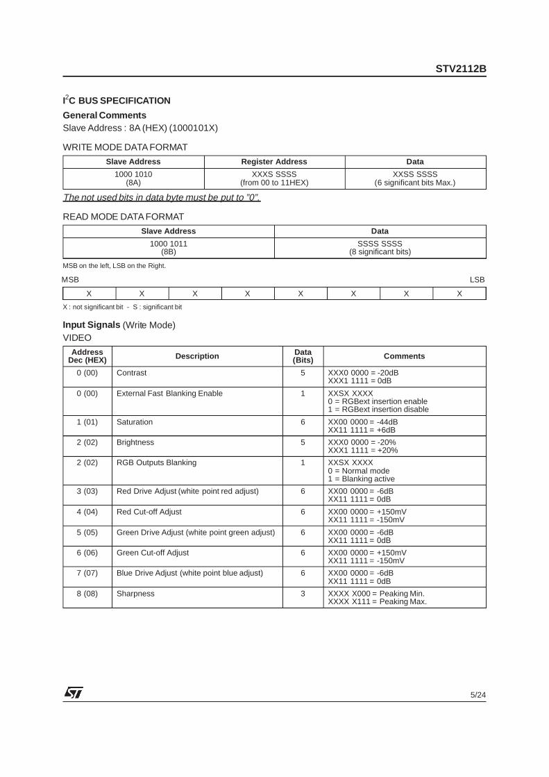
- 2 RGB inputs : RGB (OSD) input has priorityagainst the RGBext. Maximum contrast on RGB(OSD). -12dB range contrast control on RGBext.Possibility to disable the RGBext insertionthrough the bus.
- Oversize blanking capability on FB(OSD)(Pin15)input. The RGB ouputs will be blanked when thevoltage on Pin 15 will exceed the second thresh-old at 1.9V (blanking threshold) : the whole fieldis blankedbut not the inserted cut-offpulses. TheOSD insertion threshold is 0.7V.
- Automatic cut-off current loop : 2V cut-off range.Sequential cut-off current measurement duringthe three lines after the frame blanking signal.Leakage current measurement during the frameblanking, memorization on an internal capacitor.
- Warm up detector.- Beam current limiter DC voltage input.
The beam current limiter control voltage will acton contrast first, then the brightness will be de-creasedwhen contrastattenuationreaches-5dB.
- Bus control of the red, green and blue channelgain (White point adjustment)
- Bus control of the red and greenDC levels (blackpoint adjustment)
- PAL and SECAM matrix).- Switch-off of the trap filter in SVHS mode.- Buscontrolled contrast on luminance (20dBrange)- Bus controlled saturation (50dB range)- Bus controlled brightness : 40% range at maxi-
mum contrast.- Bus controlled sharpness (peaking) ; sharpness
active in PAL standard only.- Noise coring function on sharpness.
4 - CHROMA CIRCUIT4.1 - PAL/SECAM Decoders
- SVHS inputs ; bus controlled SVHS mode.- 30dB range ACC- Use of an external base band delay line
(STV2180 recommended)- Automatic standard identification, with possibility
to force the standard through the bus.
4.2 - PAL Decoder- ACC done by peak detector on synchronous de-
modulation of the burst- Fully integrated killer functions.- VCO using crystal 4.43MHz
Vibrationmode : Fondamental,series resonance(no serial capacitor)Motional capacity : 13fF ±3fFResonance resistance : < 70ΩShunt capacitance: < 7pFSpurious response : No resonance at 3*fo ±3kHz
- 0o and ±90o demodulationangles for PAL
4.3 - SECAM Decoder- ACC- Fully integrated killer- Two integrated discriminators with two PLL- Integrated deemphasis
4.4 - Standard Identification- Sequential identification.- 2 identification sequences :
PAL mode, SECAM mode- PAL priority- the SECAM mode is locked after two identified
SECAM sequences- the SECAM mode can be selected in 50Hz only- Blanking of the (R-Y) and B-Y) outputs during
color search mode.
5 - OTHER FUNCTIONS : IF CONTROLS5.1 - VolumeControl and Mute
The volume controlvoltage rangeon Pin 10 is from0.5V to 5V.
A low voltage on Pin 10 (below 0.2V) will mute theFM demodulator of the IF circuit STV8224.
It will put the volume at the minimumlevel and thusthere will be no soundeither in TV modeor SCARTmode.
The volume control voltage and the mute level arecontrolled by the bus.
5.2 - IF Standard and TV/SCART Mode Selection
The selection of IF standard (positive or negativevisionmodulation)and theTV/SCARTmode is con-trolled by the bus. Theselection is convertedin fourvoltages on Pin 21.
The lowest voltage selects the TV mode and theNEGATIVE vision modulation.
The highest voltage (open collector output withinternal pull-up resistor to VCC) selects the SCARTmode and the NEGATIVE vision modulation.
The two other intermediate voltages select eitherTV mode and POSITIVE vision modulation orSCART mode and POSITIVE vision modulation.
FUNCTIONAL DESCRIPTION (continued)
STV2112B
4/24
I2C BUS SPECIFICATION
General CommentsSlave Address : 8A (HEX) (1000101X)
WRITE MODE DATA FORMAT
Slave Address Register Address Data
1000 1010(8A)
XXXS SSSS(from 00 to 11HEX)
XXSS SSSS(6 significant bits Max.)
The not used bits in data byte must be put to ”0”.
0001 = Not allowed0010 = Not allowed0011 = Not allowed0101 = Not allowed1000 = Not allowed1001 = Not allowed1010 = Not allowed1011 = Not allowed111X = Not allowed1100 = Not allowed1101 = Not allowed
S/N Signal to Noise Ratio of Output (VPP/VRMS)4.43MHz PAL Signalon Y/CVBS Input
No signal on R-Y, B-Y inputsContrast Max., Drive Max.,Saturation Typ., Sharp Typ.,Bandwidth 5MHz
50 dB
Res Residual Frequency at fOSCat 2 fOSC and Higher Harmonics
PAL/SECAMPAL/SECAM
2510
10050
mVPPmVPP
FILTERS
VTUN1 Tuning Voltage Range (Pin 8) 3.2 to 4.8 V
VTUN2 Cloche Tuning Voltage Range (Pin 9) 2.5 to 6.5 V
Y DELAY LINE
td1p Delay Time PAL SVHS mode 330 370 400 nstd2 Delay Time SECAM SVHS mode 500 540 580 nstd3p Delay Time PAL CVBS mode 390 425 460 nstd4 Delay Time SECAM CVBS mode 550 590 630 ns
SHARPNESS CIRCUIT (PAL only)
fSharp Center Frequency SVHS mode 2.5 MHz
GSharp Gain Variation from Min. to Max. Sharp at fSharp 6 dBOvershoot Amplitude Variation compared to B/W 2T pulse, Sharp Max. 150 %Pre-shoot Amplitude Variation compared to B/W 2T pulse, Sharp Max. -15 %
After-shoot Amplitude Variation compared to B/W 2T pulse, Sharp Max. -40 %Coring Coring Range compared to B/W 10 %
Y TRAP FILTER
fTrap Trap Frequency PAL -0.2 fOSC +0.2 MHzTrap Frequency SECAM -0.2 4.25 +0.2 MHz
SATMax. Maximum Saturation Control (3F) 1VPP CVBS on Pin 20 5 +6.5 8 dBSATNom. Nominal Saturation Control (20) 1VPP CVBS on Pin 20 0 dBSATMin. Minimum Saturation Control(00) 1VPP CVBS on Pin 20 -44 dB
COLOUR DIFFERENCE INPUT SIGNALS (Pins 38-39)
DCRYI DC Voltage Pin 39 No colour 2.6 2.8 3.0 V
DCBYI DC Voltage Pin 38 No colour 2.6 2.8 3.0 VVRYI Input Signal Amplitude Pin 39 100/75 color bar 1.05 VPP
VBYI Input Signal Amplitude Pin 38 100/75 color bar 1.33 VPP
ICL38-39 Clamping Current During burst key 150 µA
SYNC. SEPARATOR
VSync Sync. Pulse Amplitude On Pin 20 50 300 mV
HORIZONTAL OSCILLATOR
fH50 Frequency after Divider 50Hz input signal 15625 HzfRang Frequency Control Range Low Frequency
High Frequency1450016100
1485016300
1520016500
HzHz
ffree Free Running Frequency when PLL1 open Value 03hexin register 0Ehex
15000 15800 Hz
FIRST LOOP FILTER (Pin 33)
ILOW-33 Long Time Constant Output Current 0.12 0.15 0.18 mAIHIGH Short Time Constant Output Current 0.35 0.45 0.55 mA
I V LOW Very Long Time Constant 0.02 0.03 0.05 mA
SECOND CONTROL LOOP
CRQ2 Control Range from Start of HorizontalOutput to Flyback
Symbol Parameter Test Conditions Min. Typ. Max. Unit
IF STANDARD CONTROL & SWITCH SELECTION (Pin 11)
VTV/NEG Output Voltage in TV Mode andNegative Vision Modulation
VCC = 9V 0.1 0.7 V
VTV/POS Output Voltage in TV Mode andPositive Vision Modulation
VCC = 9V 2.90 3.37 3.80 V
VStart/Pos Output Voltage in SCART Mode andPositive Vision Modulation
VCC = 9V 5.20 5.62 6.10 V
VStart/Neg Output Voltage in SCART Mode andNegative Vision Modulation (open collector mode)
VCC = 9V 7.88 9 V
RTV/Neg Output Resistance in TV Mode andNegative Vision Modulation
200 Ω
RTV/Pos Output Resistance in TV Mode andPositive Vision Modulation
6.7 kΩ
RScart/Pos Output Resistance in Scart Mode andPositive Vision Modulation
11 kΩ
RScart/Neg Output Resistance in Scart Mode andNegative Vision Modulation (pull-up resistor to VCC)
18 kΩ
I2C BUS INPUTS (Pins 6-7)
VTH6-7 Threshold Voltage 1.5 2.25 3 VCL6-7 Capacitance of each Pin 5 10 pF
ILeak6-7 Leakage Current Write Mode,0 level on SDA or SCL
50 µA
2112
B-0
8.T
BL
STV2112B
14/24
USER CONTROLS
%120
80
40
0
100
60
20
00 10 1F
Code (HEX) 2112
B-0
3.E
PS
Figure 1 : Contrast Control Curve
%30
10
(10)
(30)
20
0
(20)
00 10 1F
Code (HEX) 2112
B-0
5.EP
S
Figure 3 : Brightness Control Curve
%160
0 7
Code (HEX)
901 2 3 4 5 6
150
130
140
110
120
100
2112
B-06
.EPS
Figure 4 : Peaking Control (2T overshoot)
%250
00 20 3F
Code (HEX)
10 300
200
150
100
50
2112
B-0
4.E
PS
Figure 2 : Saturation Control Curve
Output Voltage (Pin 10)6
00 20 3F
Code (HEX)
10 300
3
5
4
2
1
2112
B-0
7.EP
S
Figure 5 : Volume Control Curve
STV2112B
15/24
INPUT/OUTPUT PIN CONFIGURATION
Pins 2-3
VCC2
GND2
2112
B-0
8.E
PS
Figure 6 : Pins 2, 3 - CXTL1, SELECT
4
VCC2
GND2
2112
B-0
9.E
PS
Figure 7 : Pin 4 - CLPF
5
GND2
VCC2
2112
B-1
0.E
PS
Figure 8 : Pin 5 - ACC
6
VCC2
GND2
2112
B-1
1.E
PS
Figure 9 : Pin 6 - SDA
7
VCC2
GND2
2112
B-1
2.E
PS
Figure 10 : Pin 7 - SCL
8
VCC1VCC2
GND2
2112
B-1
3.E
PS
Figure 11 : Pin 8 - FTUN1
STV2112B
16/24
INPUT/OUTPUT PIN CONFIGURATION (continued)
9
VCC2
GND2
2112
B-1
4.EP
S
Figure 12 : Pin 9 - FTUN2
10
GND2
VCC2
2112
B-1
5.EP
S
Figure 13 : Pin 10 - Volume
11
VCC2
GND2
2112
B-1
6.E
PS
Figure 14 : Pin 11 - SWI
GND1
VCC1
Pins 12-13-1416-17-18
2112
B-1
7.E
PS
Figure 15 : Pins 12,13,14,16,17,18- RGB Inputs
Pins 15-19
VCC1
GND1
2112
B-1
8.E
PS
Figure 16 : Pins 15,19 - FBOSD, FBEXT
20
GND1
VCC1 VCC2
2112
B-1
9.E
PS
Figure 17 : Pin 20 - Y/CVBS
STV2112B
17/24
INPUT/OUTPUT PIN CONFIGURATION (continued)
23
GND2
VCC1VCC2
2112
B-2
0.E
PS
Figure 18 : Pin 23 - CHR/SVHS
30
VCC1
GND1
Pins 24-25-26
2112
B-2
1.E
PS
Figure 19 : Pins 24, 25, 26 - CG, CR, CB
Pins 27-28-29
GND1
VCC1
2112
B-2
2.EP
S
Figure 20 : Pins 27, 28, 29 - BO, GO, RO
30
VCC1
GND1
2112
B-2
3.EP
S
Figure 21 : Pin 30 - ICAT
31
GND1
VCC1VCC1
2112
B-2
4.E
PS
Figure 22 : Pin 31 - BCL
32
VCC2
GND2
2112
B-2
5.E
PS
Figure 23 : Pin 32 - SXTL
STV2112B
18/24
INPUT/OUTPUT PIN CONFIGURATION (continued)
33
GND2
VCC2
2112
B-2
6.E
PS
Figure 24 : Pin 33 - SLPF
34
VCC2
GND2
2112
B-2
7.E
PS
Figure 25 : Pin 34 - VAMP
35
VCC2
GND2
2112
B-2
8.E
PS
Figure 26 : Pin 35 - VOUT
36
GND2
VCC2
2112
B-2
9.E
PS
Figure 27 : Pin 36 - HOUT
37
VCC2
GND2
2112
B-3
0.E
PS
Figure 28 : Pin 37 - LFB/SC
GND2
VCC1VCC2
Pins 38-39
2112
B-3
1.E
PS
Figure 29 : Pins 38, 39 - BYI, RYI
STV2112B
19/24
Pins 40-41
VCC2
GND2
2112
B-3
2.E
PS
Figure 30 : Pins 40, 41 - RYO, BYO
1
42
21
22
GND2 GND1
VCC2 VCC1
2112
B-3
3.E
PS
Figure 31 : Pins 42, 22 - VCC2, VCC1
INPUT/OUTPUT PIN CONFIGURATION (continued)
STV2112B
20/24
10nF
10nF
10nF
10nF
100nF
100nF
220nF
22nF
22nF
22nF
22nF
22nF
22nF
1
2
3
4
5
6
7
8
9
10
16
17
18
19
20
26
27
28
29
30
36
37
38
40
11
12
13
14
15
21 22
23
24
31
32
33
34
35
25
39
41
423.58MHz
4.43MHz
33nF
100nF
100nF
503kHz
100nF
470µF16V
9V
100nF
470µF16V 9V
470Ω
470Ω
470Ω
100Ω100Ω
47pF
100Ω
47pF
100nF
270kΩ
330kΩ
4.7nF
18kΩ
1kΩ9V
TODEFLECTIONS TAGES
TOCRTAMPLIFIERS
75Ω
Y/CVBSInput 1VP P
1kΩ
10nF
CHROMA INPUT (S-VHS)
75Ω
I2C BUS
TO STV8224
47kΩ
100nF
220kΩP in 22 1N4148
22kΩ3.3nF
1µF50V
P in 42
75Ω
75Ω
75Ω
75Ω
FROMEXTERNAL
RGB
390Ω
1kΩ
FROMOS D
+TXT
3.9kΩ
3.9kΩ
3.9kΩ
2.2kΩ
390Ω
390Ω
1
2
3
4
5
6
7 8
9
10
11
12
13
14
100nF
100nF
4.02kΩ1%
1nF
47µF16V
10Ω
9V
4.7nF
15kΩ
1µF
1N4148
680Ω4.7kΩ
9V
4.7kΩ
1N4148STV2112B
STV2180
FROMHORIZONTALSTAGE
LFB (Heater)
18kΩ
100nF
TO P in 42
S DA
S CL
VOL
SWI
3.3pF
OBLK(overs izeblanking)
GND2
S ELECT
CXTL1
CLPF
VCC 2
BYO
RYO
BYIACC
S DA
S CL
FTUN1
RYI
LFB/S C
HOUT
VOUT
VAMP
S LPF
S XTL
BCL
ICAT
FTUN2
VOL
S WI
BOS D
GOS D
ROS D
FBOS D
BEXT
RO
GO
BO
GEXT
REXT
FBEXT
CR
CB
CG
Y/CVBS
GND1
CHR/S VHS
VCC 1
2112
B-3
4.E
PS
Notes : - STV2112B requires only 1 XTAL (4.43MHz).- Recommended 4.43MHz XTAL is JAUCH Number 10080082.- XTAL2 selection pin (Pin 2) : we recommend the connection to VCC2 (Pin 42).
In the case of STV2112B version, this pin can be left open.
APPLICATION DIAGRAM
STV2112B
21/24
1
2
3
4
5
6
7
8
9
10
10kΩ
47nF
220nF2.2Ω
100µF35V1N4004
+24V
1000µF25V
4.7kΩ
1000µF25V
1000µF25V
270Ω
1.8kΩ
47µF25V
3.9kΩ
22Ω2W
470Ω
Vertical Yoke+12V
1.2Ω
1.3kΩ
160kΩ
330kΩ
620kΩ
15kΩ15kΩ
+9V100nF
47nF
1N4148100kΩ
1kΩ
15kΩ
620kΩ
BC547
4.7µF
470kΩ
+9V
100kΩ
100kΩ
560kΩ
BC557
BC547
56kΩ
OPTIONAL 4/3 - 16/9 SWITCHING
27kΩ
VOUT(From STV2112B
Pin 35)
VAMP(From STV2112B
Pin 34)
OUT
V+
V.SYNC
V.SIZE
GND
SAW
BUFF
FEEDB
VCC
FLYB
TDA1771
2112
B-3
5.E
PS
90o CRT APPLICATIONS VERTICAL STAGE
STV2112B
22/24
R30470Ω
C44220nF
1
2
3
4
5
6
7
8 9
10
16
11
12
13
14
15
T5BC547
VerticalYoke
D81N4148
C484.7nF
C5133nF
R18330Ω
R17330Ω
SCL
SDA
VRET
REG
VC C
LPF
CVERT
GND
S ENS M
SENS P
FROUT
EWOUT
EWIN
OBLK
HFLY
BREATH
STV2145
C34100pFF
VCC
C2047µF
C56220nF
R524.7kΩ
+9V
R812.4kΩ
+12V
SDA
VOUT
SCL
R5722kΩ
HFLY
R55100kΩ
C541nF R54
680kΩ
VC C
R56220kΩ
R46100kΩ
BCL
R456.2kΩ
VCC
C371nF
C3910nF
C3610nF
R31100Ω
R28100Ω
R203.6Ω
R191.2Ω
R3330Ω
C52200µF
R210Ω3W
+12V
R431kΩ
T6TIP122
C463.3nF
R4739kΩ
R413.3kΩ
C684.7µF160V
E/W MODULATOR
OBLK
VCC
R501.5kΩ
To STV2112BPin15
C41000µF25V
FromSTV2112B
Pin35
C10220nF
R121.5Ω
R363.3kΩ
C311.5nF
D41N4148
D21N4148
1
2
3
4
5
6
7
IN-
OUT
FLYBACK
GND
VCC
OUT VCC
IN+
TDA8172
+24V
C91000µF
35V
D11N4004
+24V
C23100µF
C4322pF
R2610kΩ
+12V
2112
B-3
6.E
PS
110o CRT APPLICATIONS : Vertical System with East-West
Information furnished is believed to be accurate and reliable. However, STMicroelectronics assumes no responsibility for theconsequences of use of such information nor for any infringement of patents or other rights of third parties which may result fromits use. No licence is granted by implication or otherwise under any patent or patent rights of STMicroelectronics. Specificationsmentioned in this publication are subject to change without notice. This publication supersedes and replaces all informationpreviouslysupplied. STMicroelectronics products are not authorized for use as critical comp onents in lifesupport devicesor systemswithout express written approval of STMicroelectronics.
The ST logo is a registered trademark of STMicroelectronics
1998 STMicroelectronics - All Rights Reserved
Purchase of I 2C Components of STMicroelectronics, conveys a license under the Philips I 2C Patent.Rights to use these components in a I 2C system, is granted provided that the system conforms to
the I 2C Standard Specifications as defined by Philips.
STMicroelectronics GROUP OF COMPANIESAustralia - Brazil - Canada - China - France - Germany - Italy - Japan - Korea - Malaysia - Malta - Mexico - Morocco - The Netherlands
Singapore - Spain - Sweden - Switzerland - Taiwan - Thailand - United Kingdom - U.S.A.


![BUS BUS BUS BUS BUS BUS BUS BUS BUS · Sunday 15 May 2016 Liverpool Street to Colchester, Ipswich, Norwich and branches BUS BUS BUS BUS BUS BUS BUS BUS BUS] 1 1 1 1 1 1 1 1 1 1 1](https://static.documents.pub/doc/80x56/5fab4ce2477d2d3adf21016a/bus-bus-bus-bus-bus-bus-bus-bus-sunday-15-may-2016-liverpool-street-to-colchester.jpg)


