14
Bushing Series Service Manual
Bushing Series Service Manual

Tool List and Kits1. Arbor Press2. Bearing Puller3. Bushing Removal Kit4. Collets5. Bushing Installation Kit6. Soft Face Hammer7. Medium Grit Stone8. Oil and Grease9. Torque Wrench10. Bench Vise11. Crayon or Marker12. Permatex Aviation Form-A-Gasket #313. Snap Ring Pliers14. Lip Seal Install Plug15. Motor Seal Expansion Sleeve
Bushing Insertion Kits124 Series - T-1194197 Series - T-1188257 Series - T-1175360 Series - T-1199
Kits includes insertion tool and guide or see sketches to right.
Tool List
Motor Seal Expansion Sleeve
Series A Dia. B Dia. C D Collet OTC #
124 0.920/0.940 0.830/0.850 0.085/0.095 1.22/1.28 T-1195 33863
197 Stock Stock 0.085/0.095 Stock T-1170 33863
257 1.260/1.280 1.140/1.160 0.060/0.070 As Shown T-1174 33865
360 1.372/1.382 1.250/1.260 0.100/0.120 As Shown T-1202 33865
Series A B Dia. C Dia. D Dia. E F Dia. G. Dia.
124 1.307/1.312 0.939/0.941 1.057/1.059 2.00 1.298/1.302 2.000 1.067/1.069
197 1.410/1.415 1.119/1.121 1.275/1.277 2.00 1.395/1.400 2.375 1.285/1.287
257 1.811/1.815 1.286/1.288 1.443/1.445 1.94 1.800/1.804 1.940 1.453/1.457
360 2.002/2.004 1.496/1.498 1.655/1.657 2.50 1.999/2.001 2.500 1.665/1.667
Series Tool Part # A B Dia. C Dia.
124 Q-1956-5 2.500 0.885/0.889 0.940/0.944
257 Q-1956-3 2.500 1.250/1.254 1.286/1.290
360 Q-1956-2 2.500 1.259/1.263 1.379/1.383
Bushing Removal
Need 1 kit (T-1243) plus the collet for each series or the OTC collet modified per sketch shown above.
Bushing Insertion
“C”R 0.020 MAX.
“A” DIA.
“B” DIA.“D”
“D” DIA.
0.50 “A” 0.25
“B” DIA.“C” DIA.
0.03 x 45°
0.06 x 45°
“E”
“G” DIA.
0.06 x 45°4 Places
“B” DIA.“C” DIA.
“A”
“F” DIA.
1

Bushing Series Service Manual
1. Retaining Ring2. Outboard Bearing (Optional)3. Shaft Seal4. Shaft End Cover5. Journal Bushing6. Back up Ring7. Seal Ring8. Thrust Plate
9. Housing Gasket10. Integral Gear Set11. Continental Gear Set12. Dowel Pin13. Gear Housing14. Port End Cover (Single)15. Washer16. Hex Head Bolt17. Bearing Carrier18. Connecting Shaft19. Port End Cover (Tandem)20. Tie Bolt21. Hex Nut22. Spacer (Motor only)23. Check Valves for Motors,
Plugs according to BOM
Single Port End Cover
15
12
2115
5
5
67
8
9
11
12
9
87
65
5
12
12
13
19
20
15
20
21
21
17
18
15
16
15
12
15
16
16
15
14
13
12
12
5
56
78
9
12
10
9
87
6
5
5
4
3
2
1
23
23
22
Multiple Sections
Tandem Port End Cover
General Notes1. Read all instructions prior to disassembly and assembly to familiarize yourself with all steps required.
2. All areas and tools should be clean in the work area, and all parts clean and wiped with a lintless cloth before assembly.
3. Make sure all components are prepared and marked (if needed) for the correct rotation.
4. Use only Geniune Permco parts, as other manufacturers’ parts may not fit in all Permco assemblies.
5. Refer to bushing diagrams included for each series on page 9-10.
6. Tear down and assembly shown is a P257 2 section pump.
2

Start Disassembly1.Place pump in vise as shown and scribe a line down the pump from port end cover to shaft end cover. This line will be used for reassembling. DO NOT GRIP ON OR NEAR ANY MACHINED SURFACES DURING ASSEMBLY OR DISASSEMBLY
2.Remove the 4 fasteners with a socket or impact wrench.
4.Remove the thrust plate and inspect. (See Page 8)
3.Remove port end cover by inserting screwdrivers into pry- pockets on the side of the gear housing. Be careful not to damage machined surfaces.
5.Multiple Units Only Remove gear set keeping gears together. Remove thrust plate from bearing carrier. Examine gear set and thrust plate for replacement. (See Page 8)
6.Multiple Units Only Remove gear housing from bearing carrier by using screwdrivers inserted into the pry-pockets. Examine for replacement. (See page 8)
3
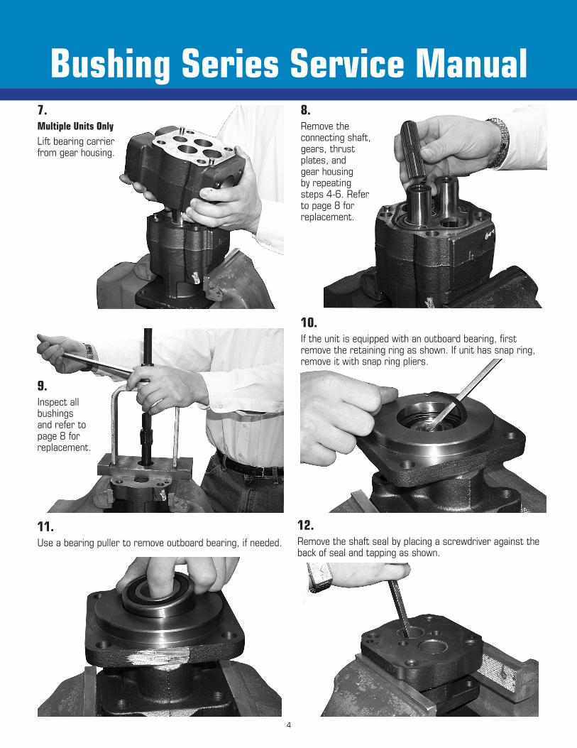
Bushing Series Service Manual8.Remove the connecting shaft, gears, thrust plates, and gear housing by repeating steps 4-6. Refer to page 8 for replacement.
7.Multiple Units OnlyLift bearing carrier from gear housing.
9.Inspect all bushings and refer to page 8 for replacement.
10.If the unit is equipped with an outboard bearing, first remove the retaining ring as shown. If unit has snap ring, remove it with snap ring pliers.
11.Use a bearing puller to remove outboard bearing, if needed.
12.Remove the shaft seal by placing a screwdriver against the back of seal and tapping as shown.
4

Single and Tandem Assembly
1.Stone all faces with a medium grit stone.
2.Deburr all bushing bores with emery cloth to assure bushings do not become galled during installation.
3.Apply a thin film of Permatex Aviation Form-A-Gasket #3 around the O.D. of the lip seal. With the metal side up, press the seal into bore until it is flush with the recessed face.
4.It is recommended that insertion tools manufactured by Permco be used for pressing in bushings. Refer to sketches for bushing orientation and plug (check valve) location.
1. Shaft End Cover, Gear Housing, Bearing Carrier, and Port End Cover: Stone or file mating surfaces to remove any raised metal generated in shipping or handling.2. Gear Shafts, Gears: Stone faces of gears to remove any raised metal generated in shipping and handling.3. Bearing Carrier and Port End Cover: Probe all bushing drain passages to insure that none are blocked.4. Gear Housing: Use a deburring knife to break the edge on the gear bores and dowel pin holes to ease as-sembly. Clean foreign material from dowel pin holes and gasket grooves.5. Shaft End Cover, Bearing Carrier, and Port End Cover: Use a deburring knife to break the edge of bushing and dowel pin holes to ease assembly. Clean foreign material from dowel pin holes. Use a flapper wheel or emery cloth on edge of the bushing bores to create a small radius.6. Shaft End Cover, Bearing Carrier, and Port End Cover: Mark the faces to indicate low and high pressures. This will ensure proper bushing orientation.
5

Bushing Series Service Manual
7.Install spirolox retaining ring as shown.
8.Start pin in hole straight, and tap lightly with a soft hammer.
9.Grease gasket seal and place in groove of gear housing. Place gear housing on dowel pins and tap flush with shaft end cover. Make sure large core of 124, 197, or 360 is on inlet side.
10.Place a liberal amount of grease in plate groove(A). Place rubber element in groove with recess up for nylon backup.(B)Place backup in recess ofseal ring.(C)
5.Install bushings with the lube grooves and butt joints as shown on Page 9-10.
124 Series shown in this example
AB
C
PUMP
6.If unit has an outboard bearing install as shown. For motors install spacer (22) first.
6

Single and Tandem Assembly
12.Squirt oil into bushings and on thrust plates and slide gears into gear housing. For motors protect the seal by placing a seal instertion sleeve onto gear.
13.Slide thrust plate over gears with seals facing up and trapping pocket on pressure side. Tap dowel pins into gear housing.
14.Multiple Units Only Position bearing carrier over gear
journals and dowel pins. Gently tap until the parts are together.
Check bearing carrier port orientation.
15.Multiple Units Only Insert connecting shaft into the
drive gear spline. Place the second
gear housing on the bearing carrier by
repeating steps 8-9.
11.Slip the thrust plate into the gear housing with the “T” or “U” shaped trapping pocket up and on the outlet side.
7
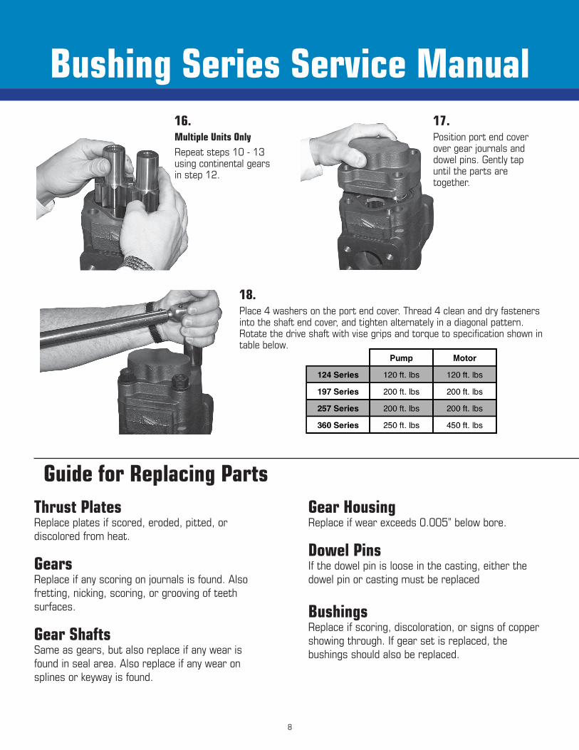
Bushing Series Service Manual16.Multiple Units OnlyRepeat steps 10 - 13 using continental gears in step 12.
17.Position port end cover over gear journals and dowel pins. Gently tap until the parts are together.
18.Place 4 washers on the port end cover. Thread 4 clean and dry fasteners into the shaft end cover, and tighten alternately in a diagonal pattern. Rotate the drive shaft with vise grips and torque to specification shown in table below.
Guide for Replacing PartsThrust PlatesReplace plates if scored, eroded, pitted, or discolored from heat.
GearsReplace if any scoring on journals is found. Also fretting, nicking, scoring, or grooving of teeth surfaces.
Gear ShaftsSame as gears, but also replace if any wear is found in seal area. Also replace if any wear on splines or keyway is found.
Gear HousingReplace if wear exceeds 0.005” below bore.
Dowel PinsIf the dowel pin is loose in the casting, either the dowel pin or casting must be replaced
BushingsReplace if scoring, discoloration, or signs of copper showing through. If gear set is replaced, the bushings should also be replaced.
8

Bushing InstallP124/M124
P197 M197
OUTLETINLET
Install bushings as shown with butt joints located at 12:00 and 6:00 o’clock. Bushings must be flush to slightly below surface.
Install P197 series bushings with lube grooves and butt joints as shown for optimum performance. However, bushings may alternately be installed per M197 diagram and must be flush to slightly below the surface.
9
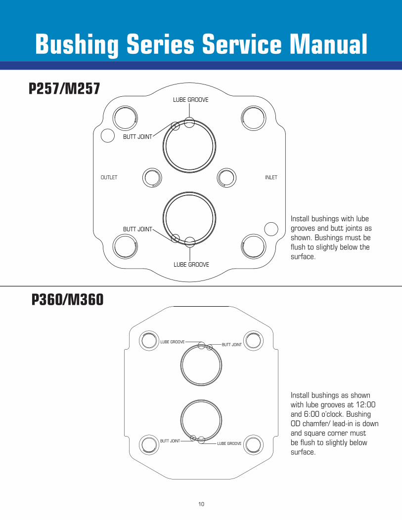
Bushing Series Service ManualP257/M257
P360/M360
Install bushings with lube grooves and butt joints as shown. Bushings must be flush to slightly below the surface.
Install bushings as shown with lube grooves at 12:00 and 6:00 o’clock. Bushing OD chamfer/ lead-in is down and square corner must be flush to slightly below surface.
OUTLET INLET
10

Bushing Series Service Manual
Testing Procedure Do not test the unit above the working pressure of the destined application. This will minimize unnecessary
housing wipe and assure optimum volumetric output.
0-15 seconds @ 0 psi 136-150 seconds @ 2500 psi 16-30 seconds @ 500 psi 151-165 seconds @ 0 psi 31-45 seconds @ 0 psi 166-180 seconds @ 3000 psi 46-60 seconds @ 1000 psi 181-195 seconds @ 0 psi 61-75 seconds @ 0 psi 196-210 seconds @ 3500 psi 76-90 seconds @ 1500 psi 211-225 seconds @ 0 psi 91-105 seconds @ 0 psi 226-240 seconds @ 4000 psi 106-120 seconds @ 2000 psi 241-255 seconds @ 0 psi 121-135 seconds @ 0 psi 256-270 seconds @ 4500 psi
Startup and Break-in Procedure 1. Before you begin testing, unscrew the main relief
valve on the circuit.2. Run the pump for two minutes under no load
conditions, low pressure, and low rpm (600 rpm minimum). If everything seems to function properly and no unusual sounds are heard, you may commence testing per the procedure below.
The testing for the Bushing Series units should be followed closely to assure optimum performance.
When testing a multiple unit, test one section at a time. Be sure the other sections are being supplied with adequate oil during the test procedure. The testing procedure involves loading and unloading the unit to prevent contamination of the bushings and bushing journals. In doing so, particles of contaminate generated during the load cycle will be flushed through the system during the no load cycle.
Fluid Type and Temperature Conditions1. The Bushing Series pumps and motors are
compatible with mineral base, water glycol, and invert emulsion fluids. Fluids such as phosphate ester may be used in some applications. Please consult the factory prior to using this type of fluid.
It is recommended that a premium quality hydraulic fluid with a viscosity range of 150-300 SUS (32-65 cSt.) at 100°F (38°C) be used to assure optimum performance. The normal operating viscosity range is between 55-1000 SUS (9-220 cSt.) with a start up viscosity not to exceed 2000 SUS (440 cSt.).
2. Under normal operating conditions, fluid temperatures should not exceed 180°F (82°C) for mineral base fluids and 135°F (57°C) for water glycol and invert emulsions. If temperatures greater than these values are required for a particular application, please consult your Permco representative or call the factory.
3. To assure maximum performance and life, a 10 micron return line filter with a Beta 10 rating of 2.2 is required for the system. Testing and operating a new or serviced unit without proper filtration will lead to premature failure of the shaft journals and journal bushings.
Procedures/Notes
11

Bushing Series Service Manual
12

Permco USA | 1500 Frost Road | P. O. Box 2068 | Streetsboro, Ohio 44241Copyright © 2015 © Bulletin # BSM-0116 Version 1.0
Permco is a leading manufacturer of high-pressure hydraulic gear/vane pumps and motors, flow dividers, intensifiers, and
accessories. Available in a wide variety of sizes and configurations to suit your application
needs.
www.permco.comOur online support is available 24/7/365
Email: [email protected] Call: (800) 626.2801


