INSTALLATION INSTRUCTIONS – EN | INSTALLATIEINSTRUCTIE – NL | INSTALLATIONSANLEITUNG - DE | MANUEL D’INSTALLATION - FR Business Lite & Pro 22 kW Dynamic Load Balancing Version B IMPORTANT: The charge point must have been activated online by the user to make it ready to use. This is easily completed via my.newmotion.com using the charge points serial number. The charge card must also be activated. LET OP: Om de laadpaal laadklaar te maken dient de gebruiker deze online te activeren. Dit kan via my.newmotion.com aan de hand van het serienummer. Om te kunnen laden is een geactiveerde laadpas nodig. BEACHTEN SIE: Der Nutzer muss die Ladestation online registrieren, um sie nutzen zu können. Die Registrierung lässt sich einfach über my.newmotion.com mit der Seriennummer durchführen. Um laden zu können, ist eine aktivierte Ladekarte erforderlich. REMARQUE : l’utilisateur doit activer la borne en ligne avant de pouvoir l’utiliser. Cette activation s’effectue facilement sur my.newmotion.com à l’aide du numéro de série de la borne. La carte de recharge doit également être activée.
Transcript
INSTALLATION INSTRUCTIONS – EN | INSTALLATIEINSTRUCTIE – NL | INSTALLATIONSANLEITUNG - DE | MANUEL D’INSTALLATION - FR
Business Lite & Pro 22 kWDynamic Load BalancingVersion B
IMPORTANT: The charge point must have been activated online by the user to make it ready to use. This is easily completed via my.newmotion.com using the charge points serial number. The charge card must also be activated.
LET OP: Om de laadpaal laadklaar te maken dient de gebruiker deze online te activeren. Dit kan via my.newmotion.com aan de hand van het serienummer. Om te kunnen laden is een geactiveerde laadpas nodig.
BEACHTEN SIE: Der Nutzer muss die Ladestation online registrieren, um sie nutzen zu können. Die Registrierung lässt sich einfach über my.newmotion.com mit der Seriennummer durchführen. Um laden zu können, ist eine aktivierte Ladekarte erforderlich.
REMARQUE : l’utilisateur doit activer la borne en ligne avant de pouvoir l’utiliser. Cette activation s’effectue facilement sur my.newmotion.com à l’aide du numéro de série de la borne. La carte de recharge doit également être activée.
Table of contents / Inhoudsopgave /Inhaltsverzeichnis / Table des matières
NewMotion Business Lite & Pro 22 kWDynamic Load Balancing
PLEASE CHECK THE PACKAGE CONTENTS ON RECEIPTPackage contents
Charge point Wall bracket Rubber grommets (various sizes) 1 x M4 x 20 mm bolt (Torx) 6 x M4 x 12 mm bolts (Torx) 4 x M8 x 12 mm bolts (Torx) and washers 4 x M8 x 35 mm bolts (DIN 912) and washers 2 x plastic spacers Sticker sheet for the sides of the charge point
GPRS signal (dBm) receptionThe Vodafone GPRS signal strength (2G) must be between -56 and -80 dBm (turn off 3G or 4G reception on your mobile phone if you use it to check the signal). At weaker signal, please contact NewMotion.
Space in distribution box There needs to be sufficient room in the distribution board to add any necessary circuit(s).
SAFETY The electrical system must be voltage-free during the entire installation procedure. The installation procedure must be carried out by a trained electrician who works in accordance with the relevant laws and regulations. Do not carry out installation work in rain or when the humidity is above 95%.
REQUIRED MATERIALS AND TOOLSGeneral Charge point Rubber grommets (provided) 1 x M4 x 20 mm bolt (Torx) (provided) 6 x M4 x 12 mm bolts (Torx) (provided) Power cable (see ‘Installation specifications’) Cross-head screwdriver (Pozidriv size 1) Torx screwdrivers (T20 and T45) Voltage tester Spirit level Tape measure
Dynamic Load BalancingThe charge points need to be connected via a UTP cable to enable the mutual communication required for Dynamic Load Balancing. The network configuration can be done via daisy chain or star configuration using a switch (not provided).
UTP cable (CAT5 or CAT6) RJ45 connectors Crimping tool (RJ45)
To attach the charge point to the wall bracket Wall bracket (provided) 2 x M8 x 12 mm bolts (Torx) and washers (provided) 3 x screws, at least 6.3 x 60/70 mm with washers and plugs Drill and bit
To attach the charge point to the pole in soil Pole and concrete base 4 x M8 x 12 mm bolts (Torx) and washers (provided) 4 x M8 x 35 mm bolts (DIN 912) and washers (provided) DIN screwdriver (912) Shovel
To attach the charge point to a pole in concrete Pole 4 x M8 x 12 mm bolts (Torx) and washers (provided) 4 x wedge bolts and 4 x M8 nuts Drill and bit
EN N
L DE FR
INSTALLATION INSTRUCTION – P1
SMART, SAFE & FAST CHARGING
INSTALLATION INSTRUCTION – P2
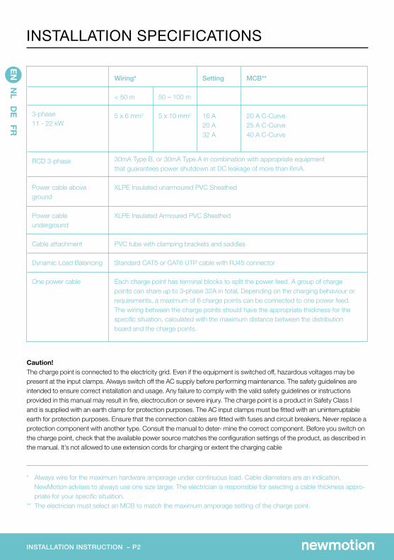
3-phase11 - 22 kW
RCD 3-phase
Power cable above ground
Power cable underground
Cable attachment
Dynamic Load Balancing
One power cable
30mA Type B, or 30mA Type A in combination with appropriate equipment that guarantees power shutdown at DC leakage of more than 6mA.
XLPE Insulated unarmoured PVC Sheathed
XLPE Insulated Armoured PVC Sheathed
PVC tube with clamping brackets and saddles
Standard CAT5 or CAT6 UTP cable with RJ45 connector
Each charge point has terminal blocks to split the power feed. A group of charge points can share up to 3-phase 32A in total. Depending on the charging behaviour or requirements, a maximum of 6 charge points can be connected to one power feed. The wiring between the charge points should have the appropriate thickness for the specific situation, calculated with the maximum distance between the distribution board and the charge points.
Wiring* MCB**
20 A C-Curve 25 A C-Curve 40 A C-Curve
Setting
16 A20 A32 A
< 50 m
5 x 6 mm2
50 – 100 m
5 x 10 mm2
* Always wire for the maximum hardware amperage under continuous load. Cable diameters are an indication, NewMotion advises to always use one size larger. The electrician is responsible for selecting a cable thickness appro-priate for your specific situation.
** The electrician must select an MCB to match the maximum amperage setting of the charge point.
EN N
L DE FR
INSTALLATION SPECIFICATIONS
Caution! The charge point is connected to the electricity grid. Even if the equipment is switched off, hazardous voltages may be present at the input clamps. Always switch off the AC supply before performing maintenance. The safety guidelines are intended to ensure correct installation and usage. Any failure to comply with the valid safety guidelines or instructions provided in this manual may result in fire, electrocution or severe injury. The charge point is a product in Safety Class I and is supplied with an earth clamp for protection purposes. The AC input clamps must be fitted with an uninterruptable earth for protection purposes. Ensure that the connection cables are fitted with fuses and circuit breakers. Never replace a protection component with another type. Consult the manual to deter- mine the correct component. Before you switch on the charge point, check that the available power source matches the configuration settings of the product, as described in the manual. It’s not allowed to use extension cords for charging or extent the charging cable
INSTALLATION INSTRUCTION – P3
Maximum charge capacity (hardware)
Electric safety category
IK code (robustness)
Dimensions
Weight
Standard colour
Designed according to
Mains connection
kWh measurement
User interface/identification
Communication
Protection class
Operating temperature
Humidity
Air pressure
Maximal mounting height
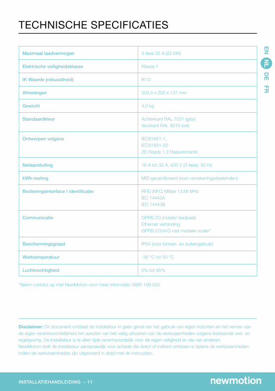
3-phase 32A (22 kW)
Class 1
IK10
503.5 x 200 x 137 mm
4.0 kg
Rear side RAL 7031 (grey)Front side RAL 9010 (white)
IEC61851-1IEC61851-22ZE-Ready 1.2 Requirements
16 A to 32 A, 400 V (3-phase), 50 Hz
MID certified (for billing purposes)
RFID (NFC) Mifare 13.56 MHzIEC 14443AIEC 14443B GPRS 2G (master charge point)Ethernet connectionGPRS 2/3/4G with mobile router*
IP54 (for internal and external use)
-30 °C to 50 °C
5% to 95%
860 hPa and 1060 hPa
1.5 meter
Disclaimer: This document does not remove the need for an electrician’s insight to ensure that the installation work is carried out safely and in accordance with the relevant legislation and regulations. Electricians are responsible at all times for their own safety and for the safety of others. If the installation work is not carried out in accordance with these instructions, the electrician is liable for any damage that arises directly or indirectly as a result of the installation work.
*Contact NewMotion for further information: +44 20 3868 1036 and press option 1.
EN N
L DE FR
TECHNICAL SPECIFICATIONS
AA
BB
CC
DD
EE
FF
8 8
7 7
6 6
5 5
4 4
3 3
2 2
1 1
DRA
WN
CH
K'D
APPV
'D
MFG
Q.A
UN
LESS OTH
ERWISE SPEC
IFIED:
DIM
ENSIO
NS A
RE IN M
ILLIMETERS
SURFA
CE FIN
ISH:
TOLERA
NC
ES: LIN
EAR:
AN
GU
LAR:
FINISH
:D
EBURR A
ND
BREA
K SHA
RP ED
GES
NA
ME
SIGN
ATU
RED
ATE
MA
TERIAL:
DO
NO
T SCA
LE DRA
WIN
GREV
ISION
TITLE:
DW
G N
O.
SCA
LE:1:5SH
EET 1 OF 1
A3
WEIG
HT:
Business PRO
INSTALLATION INSTRUCTION – P4
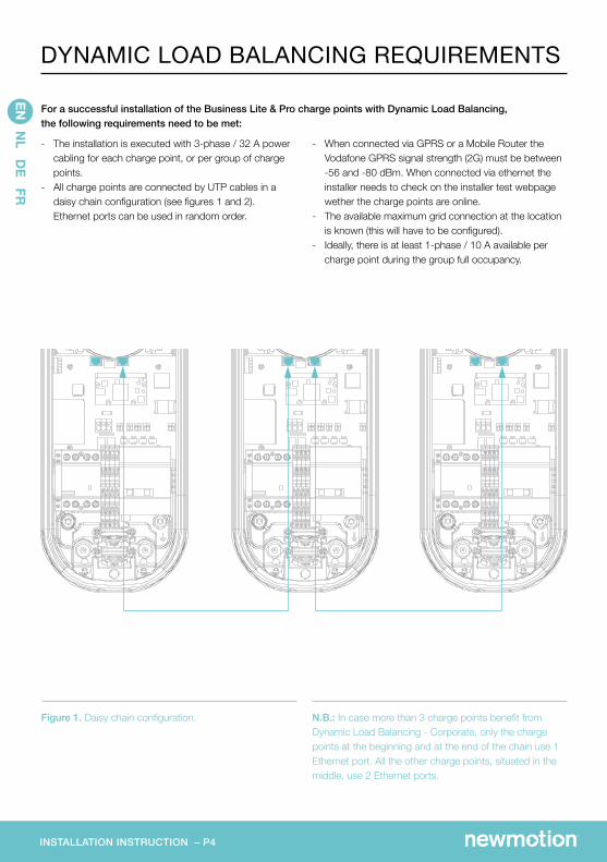
Figure 1. Daisy chain configuration. N.B.: In case more than 3 charge points benefit from Dynamic Load Balancing - Corporate, only the charge points at the beginning and at the end of the chain use 1 Ethernet port. All the other charge points, situated in the middle, use 2 Ethernet ports.
- When connected via GPRS or a Mobile Router the Vodafone GPRS signal strength (2G) must be between -56 and -80 dBm. When connected via ethernet the installer needs to check on the installer test webpage wether the charge points are online.
- The available maximum grid connection at the location is known (this will have to be configured).
- Ideally, there is at least 1-phase / 10 A available per charge point during the group full occupancy.
- The installation is executed with 3-phase / 32 A power cabling for each charge point, or per group of charge points.
- All charge points are connected by UTP cables in a daisy chain configuration (see figures 1 and 2). Ethernet ports can be used in random order.
For a successful installation of the Business Lite & Pro charge points with Dynamic Load Balancing, the following requirements need to be met:
EN N
L DE FR
DYNAMIC LOAD BALANCING REQUIREMENTS
INSTALLATION INSTRUCTION – P5
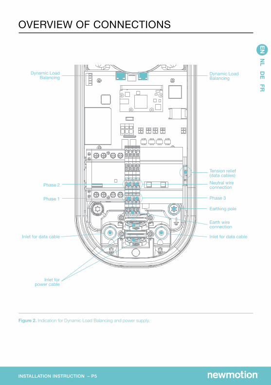
Figure 2. Indication for Dynamic Load Balancing and power supply.
Proceed steps 1 to 7 for each charge point and continue to step 8. 1. Prepare the cabling (see installation specifications).2. Attach the wall bracket at the desired height (+/- 1
metre) on the wall.3. Twist the socket lid or dummy socket anti-clockwise
and out of the cover of the charge point. Then pull the cover from the rear edge to open the charge point. Do not use any objects or tools to do this.
4. Put the charge point on the wall bracket to check its placement. On the wall, mark the positioning of the bottom two attachment points of the charge point and select the appropriate fixtures (plugs, screws and washers).
5. Secure the charge point to the wall bracket using the two M8 x 12 mm bolts and washers provided. Then secure the charge point to the wall using the bottom two attachment points. Ensure that the grey spacers are placed on the back of the charge point at the bottom two attachment points.
6. Select the appropriate grommet that suits the cable width and place it on the opening of the power cable inlet. Moisten if necessary to make it easier to feed the power cable through.
7. Secure the power cable using the cable clamp.8. Phase distribution: a. Distribute for an optimal use of each phase depen- ding on parking behaviour (first cars to arrive will not park next to each other). b. Attach the phase, neutral and earth wires to the DIN rail-mounted terminal blocks. c. Adjust the phase distribution for every 3 charge
points and note down the phase distribution and serial number for each charge point (see table 1).
9. Connect UTP cables per charge point: a. Insert UTP cables using the sockets provided
left and right of the power cable inlet (see figure 2). Measure 25 cm extra UTP cable from the bottom side of the charge point.
b. If a daisy chain configuration is used, connect the UTP cables coming from the other charge points to the Ethernet ports on the network board (see figure 2). Both ports can be used in random order.
10. Attach the black grommet to the opening next to the power cable inlet to make the charge point watertight.
11. Note when using a pole: Earth the pole with the earth wire via the lower right bolt attachment on the charge point (see figure 2).
12. Connect the power cable to the mains in regular order (no adjustments: L1L2L3).
13. Switch the charge point power on. A yellow LED shines for about 30 seconds before the charge point starts up.
14. Check if all UTP cables are properly connected. If the communication between the charge points is successful, the LED indicators of the Ethernet ports should be blinking green.
15. Make sure that the charge point which will be appoin- ted as unit to control the load balancing group has sufficient GPRS signal strength and can connect to the NewMotion back-office. A quick check can be done on chargeportal.newmotion.com/test. Simply enter the serial number into the search field and click ‘Search’. ‘Online’ should appear after the serial num ber. If ‘Online’ does not appear, check whether the charge point is properly connected and try again. For persistent issues, please contact NewMotion.16. Place the cover on the charge point. Tighten the four
M4 x 12 mm bolts provided around the socket so that the cover closes on the rubber seal but the rubber seal does not deform. Tighten the other two M4 x 12 mm bolts provided on the bottom of the cover.
17. Twist the socket lid or dummy socket clockwise in the cover and lock using the M4 x 20 mm bolt provided. The bolt must be secure, but not too tight.
18. Apply the appropriate stickers provided onto the designated indented spaces of the charge point’s sides.
19. In the distribution board, indicate which MCB(s) are connected to the charge points.
N.B.: Please contact NewMotion for further (remote) configuration of the Dynamic Load Balancing group. Please keep the installation details on hand.N.B.: The charge points must have been activated online to enable charging. Activation can easily be done on my.newmotion.com using the charge points serial numbers (situated on the right side of the casing). The charge card must also be activated.
EN N
L DE FR
INSTALLATION PROCEDURE
INSTALLATION INSTRUCTION – P7
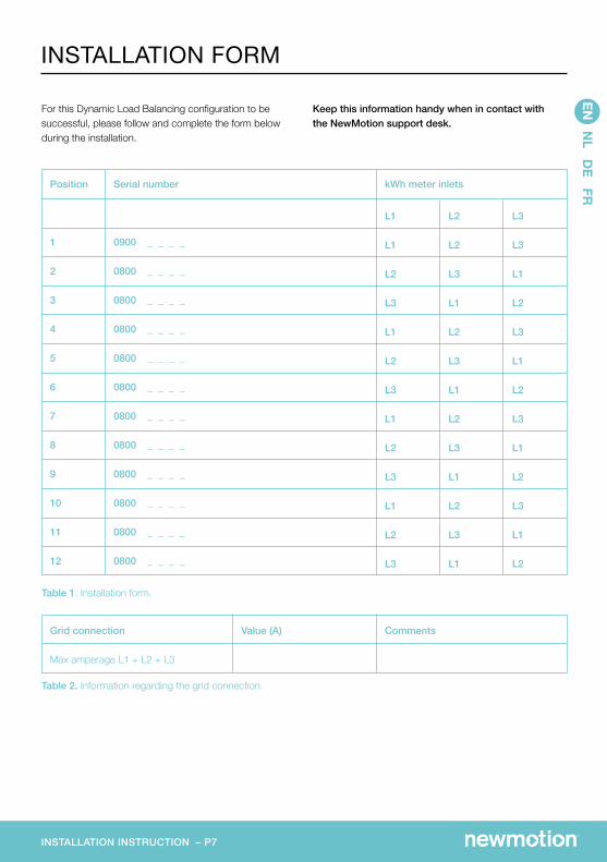
Table 1. Installation form.
Position
1
2
3
4
5
6
7
8
9
10
11
12
Serial number
0900 _ _ _ _
0800 _ _ _ _
0800 _ _ _ _
0800 _ _ _ _
0800 _ _ _ _
0800 _ _ _ _
0800 _ _ _ _
0800 _ _ _ _
0800 _ _ _ _
0800 _ _ _ _
0800 _ _ _ _
0800 _ _ _ _
kWh meter inlets
L1
L1
L2
L3
L1
L2
L3
L1
L2
L3
L1
L2
L3
L2
L2
L3
L1
L2
L3
L1
L2
L3
L1
L2
L3
L1
L3
L3
L1
L2
L3
L1
L2
L3
L1
L2
L3
L1
L2
Table 2. Information regarding the grid connection.
Grid connection
Max amperage L1 + L2 + L3
CommentsValue (A)
For this Dynamic Load Balancing configuration to be successful, please follow and complete the form below during the installation.
Keep this information handy when in contact with the NewMotion support desk.
EN N
L DE FR
INSTALLATION FORM
INSTALLATIEHANDLEIDING – P9
EN N
L DE FR
CHECK VOORAFInhoud verpakking Laadpaal Muurbeugel Rubberen doorvoertules (diverse maten) 1x bout M4x20mm (Torx) 6x bouten M4 x 12 mm (Torx) 4x bouten M8 x 12 mm (Torx) en ringen 4x bouten M8 x 35 mm (DIN 912) en ringen 2x kunststof afstandshouders Stickervel voor zijkanten laadpaal
GPRS ontvangstDe Vodafone GPRS-signaal sterkte (2G) moet tussen -56 en -80 dBm zijn (schakel 3G en 4G uit op uw mobile telefoon als u deze gebruikt om het signaal te testen). Bij slechter ontvangst, contact opnemen met NewMotion.
Ruimte in verdeelkastEr moet voldoende ruimte zijn in de verdeelkast voor eventueel benodigde extra groep(en).
VEILIGHEID De elektrische installatie dient spanningsloos te zijn gedurende de gehele installatie. Installaties dienen te worden verricht door daartoe opgeleide installateurs die werken volgens de geldende wet– en regelgeving zoals NEN 1010 en NEN 3140. Voer de installatie niet uit in de regen of bij een luchtvochtigheid van boven de 95%.
BENODIGDHEDENAlgemeen Laadpaal Rubberen doorvoertules (bijgeleverd) 1x bout M4 x 20 mm (Torx) (bijgeleverd) 6x bouten M4 x 12 mm (Torx) (bijgeleverd) Voedingskabel (zie “specificaties installatie”) Kruiskopschroevendraaier (Pozidriv maat 1) Torx schroevendraaiers (T20 en T45) Spanningszoeker Waterpas Meetlint
Dynamic Load BalancingDe laadpalen moeten middels een UTP-kabel met elkaar verbonden worden om de voor Dynamic Load Balancing nodige wederzijdse communicatie mogelijk te maken. De netwerk configuratie kan als Daisy Chain of ster configuratie doorgevoerd worden met behulp van een schakelaar (niet meegeleverd). UTP-kabel (CAT5 of CAT6) RJ45 connectoren Krimptang (RJ45)
Bij bevestiging op muurbeugel Muurbeugel (bijgeleverd) 2x bouten M8 x 12 mm (Torx) en ringen (bijgeleverd) 3x schroeven: minimaal 6.3 x 60/70 mm met ringen en pluggen Boormachine en boor
Bij bevestiging op paal in volle grond Paal en betonsokkel 4x bouten M8 x 12 mm (Torx) en ringen (bijgeleverd) 4x bouten M8 x 35 mm (DIN 912) en ringen (bijgeleverd) DIN schroevendraaier (912) Schep
Bij bevestiging op een paal op een betonnen ondergrond Paal 4x bouten M8 x 12mm (Torx) en ringen (bijgeleverd) 4x keilbouten en moeren M8 Boormachine en boor
SLIM, VEILIG & SNEL LADEN
INSTALLATIEHANDLEIDING – 10
3-fase11 - 22 kW
Aardlek 3-fase
Voedingskabel bovengronds
Voedingskabel ondergronds
Kabelbevestiging
Dynamic Load Balancing
Een voedingskabel
30mA type B, óf 30mA type A, aangevuld met geschikt materieel dat uitschakeling vande voeding waarborgt bij een DC-foutstroom van meer dan 6 mA.
YMvK
YMvK-As
PVC-buis met klembeugels en zadels
Standaard CAT5 of CAT6 UTP-kabel met RJ45-connector
Elke laadpaal heeft rijgklemmen om de voeding te verdelen. Een groep van laadpalen kan maximaal tot 3-phase 32 A in totaal delen. Afhankelijk van het laadgedrag of de eisen kunnen maximaal 6 laadpalen aan een stroomtoevoer aangesloten worden. De kabels tussen de laadpalen moeten een passende dikte hebben gebaseerd op de maximale afstand tussen de verdeler en de laapalen.
Bedrading* Zekering**
20 A C-Curve 25 A C-Curve 40 A C-Curve
Afstelling
16 A20 A32 A
< 50 m
5 x 6 mm2
50 – 100 m
5 x 10 mm2
* Bedrading altijd uitvoeren op het maximale ampèrage van de hardware bij continue belasting. Kabeldikte is een indi-catie. NewMotion adviseert om één maat groter te installeren. De installateur is verantwoordelijk voor bepaling van de vereiste kabeldikte in de specifieke situatie.
** De installateur moet een zekering kiezen die bij de maximale ampère-instelling van de laadpaal past.
EN N
L DE FR
SPECIFICATIES INSTALLATIE
Waarschuwing!De laadpaal is aangesloten op het elektriciteitsnet. Zelfs als de apparatuur is uitgeschakeld, kan een gevaarlijkeelektrische spanning optreden bij de ingangsklemmen. Schakel altijd de wisselstroomvoeding uit voor het plegen vanonderhoud. De veiligheidsvoorschriften zijn bedoeld om correcte installatie en gebruikt te verzekeren. Elke inbreuk opde geldende veiligheidsvoorschriften of instructies in deze handleiding kan leiden tot brand, elektrocutie of serieuzeverwondingen. De laadpaal is een product uit veiligheidsklasse I en wordt geleverd met een aardklem ter beveiliging. De ingangs-klemmen van de wisselstroom moeten zijn voorzien van een ononderbreekbare aarding ter beveiliging. Zorg ervoor dat de aansluitkabels zijn voorzien van zekeringen en stroomonderbrekers. Vervang een beveiligingsonderdeel nooit door een ander type. Raadpleeg de handleiding voor het juiste onderdeel. Controleer voordat u de laadpaal inschakelt dat de beschikbare spanningsbron overeenkomt met de configuratie-instellingen van het product zoals beschreven in de handleiding. Het is niet toegestaan gebruik te maken van verlengsnoeren of de laadkabel te verlengen.
GPRS 2G (master laadpaal)Ethernet verbindingGPRS 2/3/4/G met mobiele router*
IP54 (voor binnen- en buitengebruik)
-30 °C tot 50 °C
5% tot 95%
Disclaimer: Dit document ontslaat de installateur in geen geval van het gebruik van eigen inzichten en het nemen van de eigen verantwoordelijkheid ten aanzien van het veilig uitvoeren van de werkzaamheden volgens bestaande wet- en regelgeving. De installateur is te allen tijde verantwoordelijk voor de eigen veiligheid en die van anderen. NewMotion stelt de installateur aansprakelijk voor schade die direct of indirect ontstaan is tijdens de werkzaamheden indien de werkzaamheden zijn uitgevoerd in strijd met de instructies.
EN N
L DE FR
TECHNISCHE SPECIFICATIES
*Neem contact op met NewMotion voor meer informatie: 0880 109 502
INSTALLATIEHANDLEIDING – 12
Afbeelding 1.Daisy chain configuratie.
P.S.: Als meer dan 3 laadpalen gebruik maken van Dynamic Load Balancing, gebruiken alleen de laadpalen aan het begin en aan het einde van de daisy chain 1 Ethernet-poort. Alle andere laadpalen in het midden van de keten gebruiken 2 Ethernet-poorten.
- Bij een verbinding via GPRS of een Mobiele Router moet de Vodafone GPRS-signaal sterkte (2G) tussen -56 en -80 dBm zijn. Bij een ethernetverbinding moet de installateur op de installer test webpage controleren of de laadpalen online zijn.
- De maximaal beschikbare stroomcapaciteit van de locatie is bekend (deze dient geconfigureerd te worden).
- Bij voorkeur is er minimaal 1-fase / 10 A per laadpaal beschikbaar gedurende een volle bezetting.v
- De installatie wordt voor elke laadpaal doorgevoerd met 3-phase / 32 A- voedingskabels, of per laadpalen-groep.
- Alle laadpalen zijn verbonden met een UTP-kabel in een daisy chain-configuratie (zie afbeeldingen 1 en 2). Ethernet-poorten kunnen in willekeurige volgorde gebruikt worden.
Voor een succesvolle installatie van Business Lite & Pro laadpalen met Dynamic Load Balancing, moet aan de volgende voorwaarden worden voldaan:
EN N
L DE FR
DYNAMIC LOAD BALANCING VOORWAARDEN
AA
BB
CC
DD
EE
FF
8 8
7 7
6 6
5 5
4 4
3 3
2 2
1 1
DRA
WN
CH
K'D
APPV
'D
MFG
Q.A
UN
LESS OTH
ERWISE SPEC
IFIED:
DIM
ENSIO
NS A
RE IN M
ILLIMETERS
SURFA
CE FIN
ISH:
TOLERA
NC
ES: LIN
EAR:
AN
GU
LAR:
FINISH
:D
EBURR A
ND
BREA
K SHA
RP ED
GES
NA
ME
SIGN
ATU
RED
ATE
MA
TERIAL:
DO
NO
T SCA
LE DRA
WIN
GREV
ISION
TITLE:
DW
G N
O.
SCA
LE:1:5SH
EET 1 OF 1
A3
WEIG
HT:
Business PRO
INSTALLATIEHANDLEIDING – 13
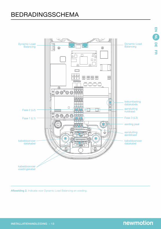
Afbeelding 2. Indicatie voor Dynamic Load Balancing en voeding.
EN N
L DE FR
BEDRADINGSSCHEMA
AA
BB
CC
DD
EE
FF
8 8
7 7
6 6
5 5
4 4
3 3
2 2
1 1
DRA
WN
CH
K'D
APPV
'D
MFG
Q.A
UN
LESS OTH
ERWISE SPEC
IFIED:
DIM
ENSIO
NS A
RE IN M
ILLIMETERS
SURFA
CE FIN
ISH:
TOLERA
NC
ES: LIN
EAR:
AN
GU
LAR:
FINISH
:D
EBURR A
ND
BREA
K SHA
RP ED
GES
NA
ME
SIGN
ATU
RED
ATE
MA
TERIAL:
DO
NO
T SCA
LE DRA
WIN
GREV
ISION
TITLE:
DW
G N
O.
SCA
LE:1:5SH
EET 1 OF 1
A3
WEIG
HT:
Business PRO
Dynamic Load Balancing
Dynamic Load Balancing
trekontlasting datakabelsaansluiting nuldraad
Fase 3 (L3)
aarding paal
kabeldoorvoerdatakabel
kabeldoorvoerdatakabel
Fase 2 (L2)
Fase 1 (L1)
aansluitingaarddraad
kabeldoorvoer voedingskabel
INSTALLATIEHANDLEIDING – 14
Volg stap 1 tot 7 voor elke laadpaal en ga dan door met stap 8. 1. Bereid de bekabeling voor, afhankelijk van de afstand
(zie “specificaties installatie”).2. Bevestig de muurbeugel op de gewenste hoogte
(+/- 1 meter) tegen de muur.3. Draai de socket-klep/dummy-socket linksom uit
de kap van de laadpaal. Trek vervolgens met enige kracht de kap van het achterste deel om de laadpaal te openen; gebruik hierbij geen gereedschap.
4. Plaats de laadpaal ter controle op de muurbeugel. Teken de onderste twee bevestigingspunten van de laadpaal af op de muur en kies geschikt bevestigings- materiaal (pluggen, schroeven en ringen).
5. Bevestig de laadpaal met 2 bijgeleverde M8 x 12 mm- bouten en ringen aan de muurbeugel. Zet de laadpaal vervolgens via de onderste twee bevestigingspunten vast aan de muur. Zorg daarbij dat aan de achterzijde van de laadpaal de grijze afstandshouders bij de onderste twee bevestigingspunten geplaatst zijn.
6. Kies, afhankelijk van de kabeldikte, het juiste formaat doorvoertule en plaats deze op de opening van de voedingskabeldoorvoer. Maak eventueel licht vochtig voor een eenvoudige doorvoer van de voedingskabel.
7. Sluit de voedingskabel aan en zet deze vast met de kabelklem.
8. Fase-verdeling: a. Verdeel elke fase voor optimaal gebruik, afhankelijk van het parkeergedrag (voertuigen, die als eerste aankomen, zullen niet naast elkaar parkeren). b. Bevestig de nuldraad, de aarddraad en de
fasedraden op de rijgklem op de DIN rail. c. Pas de fase-verdeling voor iedere 3 laadpalen aan
en noteer het serienummer van de laadpaal per fase-verdelingl (zie tabel 1).
9. In het geval van een Daisy Chain configuratie, sluit de UTP-kabels per laadpaal aan: a. Voer de UTP-kabels middels de sockets links
en rechts van de voedingskabeldoorvoer in (zie afbeelding 2). Reken 25 cm extra UTP-kabel vanaf de onderkant van de laadpaal.
b. In het geval van een Daisy Chain configuratie, sluit de UTP-kabels van de andere laadpalen aan op de
Ethernet-poorten op het netwerk board (zie afbeelding 2). Beide poorten kunnen in willekeurige volgorde gebruikt worden.
10. Plaats de zwarte doorvoertules in de opening naast de veodingskabeldoorvoer om de laadpaal waterdicht te maken.
11. Belangrijk bij paalmontage: U dient de paal via de bout bevestiging rechts onderaan met een aarddraad te aarden (zie afbeelding 2.)
12. Sluit de voedingskabel in regelmatige volgorde aan op de netspanning (geen aanpassingen L1 L2 L3).
13. Schakel de laadpaal aan. De LED geeft gedurende 30 seconden geel licht voordat de laadpaal start.
14. Controleer of alle UTP-kabels goed aangesloten zijn. Als de communicatie tussen de laadpalen succesvol is, geven de LED lampen van de Ethernet-poorten knipperend groen licht.
15. Test of het GPRS-signaal van de laadpaal die als master- laadpaal (control laadpaal) van de load balancing groep geconfigureerd wordt, voldoende sterk is om met de backoffice van NewMotion
verbonden te worden. Dit is snel te doen via chargeportal.newmotion.com/ test. Voer het serienummer in bij het zoekveld en druk op “Search”. Er dient “Online” achter het serienummer te verschijnen. Staat dit er niet? Controleer dan of de laadpaal correct is aangesloten en test daarna opnieuw. Neem bij aanhoudende problemen contact op met New Motion.16. Bevestig de kap op de laadpaal. Draai 4 bijgeleverde
M4 x 12 mm-bouten rondom de socket dusdanig aan dat de kap netjes sluit op het rubber maar het rubber niet vervormt. Draai vervolgens de andere 2 bijgeleverde M4x12 mm-bouten in de onderzijde van de kap.
17. Draai de socket-klep of dummy-socket rechtsom in de kap en vergrendel met de bijgeleverde M4 x 20mm-bout. Draai de bout goed aan maar zeker niet te strak.18. Plak de juiste bijgeleverde stickers aan de zijkanten van
de laadpaal op de daarvoor bestemde uitsparingen.19. Geef in de groepenkast aan, welke zekering(en) voor laadpalen gebruikt worden.
N.B.: Neem a.u.b. contact met NewMotion op voor de verdere (remote) configuratie van de Dynamic Load Balancing groep. Houdt a.u.b. het installatie-overzicht bij de hand. N.B.: Om de laadpaal laadklaar te maken dient de gebruiker deze online te activeren. Dit kan via my.newmotion.com aan de hand van het serienummer. Om te kunnen laden is een geactiveerde laadpas nodig.
EN N
L DE FR
STAPPENPLAN INSTALLATIE
INSTALLATIEHANDLEIDING – 15
Voor een succesvolle installatie van Dynamic Load Balancing vragen wij u om gedurende de installatie de hieronder genoemde stappen te volgen en het formulier in te vullen.
Houdt deze informatie bij de hand als u contact met NewMotion opneemt.
Tabel 1. Installatieformulier.
Positie
1
2
3
4
5
6
7
8
9
10
11
12
Serienummer
0900 _ _ _ _
0800 _ _ _ _
0800 _ _ _ _
0800 _ _ _ _
0800 _ _ _ _
0800 _ _ _ _
0800 _ _ _ _
0800 _ _ _ _
0800 _ _ _ _
0800 _ _ _ _
0800 _ _ _ _
0800 _ _ _ _
kWh meter inhammen
L1
L1
L2
L3
L1
L2
L3
L1
L2
L3
L1
L2
L3
L2
L2
L3
L1
L2
L3
L1
L2
L3
L1
L2
L3
L1
L3
L3
L1
L2
L3
L1
L2
L3
L1
L2
L3
L1
L2
Tabel 2. Informatie netaansluiting.
Beschikbare stroomcapaciteit
Maximale ampères L1 + L2 + L3
OpmerkingenWaarde (A)
EN N
L DE FR
INSTALLATIEFORMULIER
INSTALLATIONSANLEITUNG – P17
EN N
L DE FR
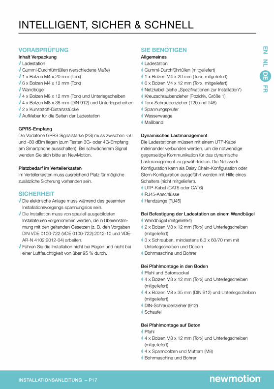
VORABPRÜFUNGInhalt Verpackung Ladestation Gummi-Durchführtüllen (verschiedene Maße) 1 x Bolzen M4 x 20 mm (Torx) 6 x Bolzen M4 x 12 mm (Torx) Wandbügel 4 x Bolzen M8 x 12 mm (Torx) und Unterlegscheiben 4 x Bolzen M8 x 35 mm (DIN 912) und Unterlegscheiben 2 x Kunststoff-Distanzstücke Aufkleber für die Seiten der Ladestation
GPRS-EmpfangDie Vodafone GPRS Signalstärke (2G) muss zwischen -56 und -80 dBm liegen (zum Testen 3G- oder 4G-Empfang am Smartphone ausschalten). Bei schwächerem Signal wenden Sie sich bitte an NewMotion.
Platzbedarf im VerteilerkastenIm Verteilerkasten muss ausreichend Platz für mögliche zusätzliche Sicherung vorhanden sein.
SICHERHEIT Die elektrische Anlage muss während des gesamten Installationsvorgangs spannungslos sein. Die Installation muss von speziell ausgebildeten Installateuren vorgenommen werden, die in Übereinstim-mung mit den geltenden Gesetzen (z. B. den Vorgaben DIN VDE 0100-722 (VDE 0100-722):2012-10 und VDE-AR-N 4102:2012-04) arbeiten. Führen Sie die Installation nicht bei Regen und nicht bei einer Luftfeuchtigkeit von über 95 % durch.
SIE BENÖTIGENAllgemeines Ladestation Gummi-Durchführtüllen (mitgeliefert) 1 x Bolzen M4 x 20 mm (Torx, mitgeliefert) 6 x Bolzen M4 x 12 mm (Torx, mitgeliefert) Netzkabel (siehe „Spezifikationen zur Installation“) Kreuzschraubenzieher (Pozidriv, Größe 1) Torx-Schraubenzieher (T20 und T45) Spannungsprüfer Wasserwaage Maßband
Dynamisches LastmanagementDie Ladestationen müssen mit einem UTP-Kabel miteinander verbunden werden, um die notwendige gegenseitige Kommunikation für das dynamische Lastmanagement zu gewährleisten. Die Netzwerk-Konfiguration kann als Daisy Chain-Konfiguration oder Stern-Konfiguration ausgeführt werden mit Hilfe eines Schalters (nicht mitgeliefert). UTP-Kabel (CAT5 oder CAT6) RJ45-Anschlüsse Handzange (RJ45)
Bei Befestigung der Ladestation an einem Wandbügel Wandbügel (mitgeliefert) 2 x Bolzen M8 x 12 mm (Torx) und Unterlegscheiben (mitgeliefert) 3 x Schrauben, mindestens 6,3 x 60/70 mm mit Unterlegscheiben und Dübeln Bohrmaschine und Bohrer
Bei Pfahlmontage in den Boden Pfahl und Betonsockel 4 x Bolzen M8 x 12 mm (Torx) und Unterlegscheiben (mitgeliefert) 4 x Bolzen M8 x 35 mm (DIN 912) und Unterlegscheiben (mitgeliefert) DIN-Schraubenzieher (912) Schaufel
Bei Pfahlmontage auf Beton Pfahl 4 x Bolzen M8 x 12 mm (Torx) und Unterlegscheiben (mitgeliefert) 4 x Spannbolzen und Muttern (M8) Bohrmaschine und Bohrer
INTELLIGENT, SICHER & SCHNELL
INSTALLATIONSANLEITUNG – P18
3-phasig11 - 22 kW
Fehlerstrom 3-phasig
Netzkabel oberirdisch
Netzkabel unterirdisch
Kabelbefestigung
Dynamic Load Balancing
30mA Typ B oder 30mA Typ A in Kombination mit zugehörigem Zubehör,das eine Stromabschaltung bei DC-Leckstrom von mehr als 6mA sicherstellt.
XLPE isoliert ungepanzert PVC ummantelt
XLPE isoliert ungepanzert PVC ummantelt
PVC-Rohr mit Klemmbügeln und Sätteln
Standardmäßiges CAT5 oder CAT6 UTP-Kabel mit RJ45-Anschluss
Verkabelung* Sicherung**
20 A C-Curve 25 A C-Curve 40 A C-Curve
Einstellung
16 A20 A32 A
< 50 m
5 x 6 mm2
50 – 100 m
5 x 10 mm2
EN N
L DE FR
SPEZIFIKATIONEN ZUR INSTALLATION
* Die Verkabelung stets bei maximaler Stromstärke der Hardware und kontinuierlicher Belastung durchführen. Die Kabeldicke ist indikativ. Die Norm berücksichtigt nicht ausreichend, dass ununterbrochen auf hoher Leistung geladen werden kann. NewMotion empfiehlt darum, ein dickeres Kabel zu installieren. Der Installateur ist dafür verant-wortlich, die erforderliche Kabeldicke in der vorliegenden Situation festzulegen.
** Der Installateur muss eine Sicherung wählen, die zur maximalen Ampere-Einstellung der Ladestation paßt.
Warnung!Die Ladestation ist an den Netzstrom angeschlossen. Selbst bei ausgeschaltetem Gerät kann an den Eingangsklem-men eine gefährliche Stromspannung vorliegen. Vor dem Durchführen von Wartungsarbeiten muss das Gerät stets vomWechselstromnetz getrennt werden. Die Sicherheitshinweise dienen der korrekten Installation und Verwendung. JeglicheMissachtung der Sicherheitsvorschriften oder -hinweise in dieser Anleitung kann zu Brandfällen, Stromschlag oderschweren Verletzungen führen. Die Ladestation ist ein Produkt der Sicherheitsklasse I und wird mit einer Schutzerdungsk-lemme ausgeliefert. Die Netz-strom-Eingangsanschlüsse müssen mit einer unterbrechungsfreien Schutzerdung ausges-tattet sein. Achten Sie darauf, die Anschlusskabel mit Sicherungen und Schutzschaltern zu versehen. Ersetzen Sie keine der Sicherheitskomponenten durch einen anderen Typ. Informationen über die korrekten Typen finden Sie im Handbuch. Vergewissern Sie sich vor dem Einschalten der Ladestation, dass die Eingangsspannung den Konfigurationseinstellun-gen des Produkts entspricht, wie im Handbuch beschrieben. Es ist nicht erlaubt, Verlängerungsschnüre zum Laden zu gebrauchen oder das Ladekabel zu verlängern.
INSTALLATIONSANLEITUNG – P19
Haftungsausschluss: Dieses Dokument entbindet den Installateur keinesfalls von seiner eigenen Sorgfaltspflicht und einer sachgerechten Ausführung der Arbeiten gemäß den geltenden Gesetzen und Vorschriften. Der Installateur ist jederzeit für die eigene Sicherheit und die Sicherheit anderer Personen verantwortlich. Werden die Arbeiten im Widerspruch zu diesen Anweisungen ausgeführt, so überträgt NewMotion die Verantwortung für Schäden, die direkt oder indirekt im Rahmen der Arbeiten entstehen, an den Installateur.
GPRS / 2G (Master-Ladestation / Hauptladestation)Ethernet-VerbindungGPRS 2/3/4G mit mobilem Router*
IP54 (für den Innen- und Außengebrauch)
-30 °C bis 50 °C
5 % bis 95 %
EN N
L DE FR
TECHNISCHE DATEN
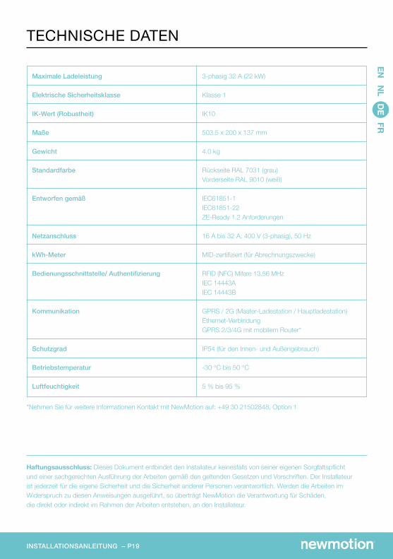
*Nehmen Sie für weitere Informationen Kontakt mit NewMotion auf: +49 30 21502848, Option 1
INSTALLATIONSANLEITUNG – P20
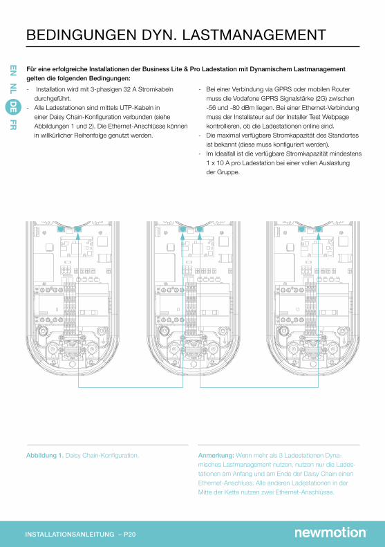
Abbildung 1. Daisy Chain-Konfiguration. Anmerkung: Wenn mehr als 3 Ladestationen Dyna-misches Lastmanagement nutzen, nutzen nur die Lades-tationen am Anfang und am Ende der Daisy Chain einen Ethernet-Anschluss. Alle anderen Ladestationen in der Mitte der Kette nutzen zwei Ethernet-Anschlüsse.
- Bei einer Verbindung via GPRS oder mobilen Router muss die Vodafone GPRS Signalstärke (2G) zwischen -56 und -80 dBm liegen. Bei einer Ethernet-Verbindung muss der Installateur auf der Installer Test Webpage kontrollieren, ob die Ladestationen online sind.- Die maximal verfügbare Stromkapazität des Standortes
ist bekannt (diese muss konfiguriert werden).- Im Idealfall ist die verfügbare Stromkapazität mindestens
1 x 10 A pro Ladestation bei einer vollen Auslastung der Gruppe.
- Installation wird mit 3-phasigen 32 A Stromkabeln durchgeführt.
- Alle Ladestationen sind mittels UTP-Kabeln in einer Daisy Chain-Konfiguration verbunden (siehe Abbildungen 1 und 2). Die Ethernet-Anschlüsse können in willkürlicher Reihenfolge genutzt werden.
Für eine erfolgreiche Installationen der Business Lite & Pro Ladestation mit Dynamischem Lastmanagement gelten die folgenden Bedingungen:
EN N
L DE FR
BEDINGUNGEN DYN. LASTMANAGEMENT
AA
BB
CC
DD
EE
FF
8 8
7 7
6 6
5 5
4 4
3 3
2 2
1 1
DRA
WN
CH
K'D
APPV
'D
MFG
Q.A
UN
LESS OTH
ERWISE SPEC
IFIED:
DIM
ENSIO
NS A
RE IN M
ILLIMETERS
SURFA
CE FIN
ISH:
TOLERA
NC
ES: LIN
EAR:
AN
GU
LAR:
FINISH
:D
EBURR A
ND
BREA
K SHA
RP ED
GES
NA
ME
SIGN
ATU
RED
ATE
MA
TERIAL:
DO
NO
T SCA
LE DRA
WIN
GREV
ISION
TITLE:
DW
G N
O.
SCA
LE:1:5SH
EET 1 OF 1
A3
WEIG
HT:
Business PRO
INSTALLATIONSANLEITUNG – P21
Abbildung 2: Angaben für Dynamisches Lastmanagement und Stromversorgung.
EN N
L DE FR
ANSCHLUSSPLAN
AA
BB
CC
DD
EE
FF
8 8
7 7
6 6
5 5
4 4
3 3
2 2
1 1
DRA
WN
CH
K'D
APPV
'D
MFG
Q.A
UN
LESS OTH
ERWISE SPEC
IFIED:
DIM
ENSIO
NS A
RE IN M
ILLIMETERS
SURFA
CE FIN
ISH:
TOLERA
NC
ES: LIN
EAR:
AN
GU
LAR:
FINISH
:D
EBURR A
ND
BREA
K SHA
RP ED
GES
NA
ME
SIGN
ATU
RED
ATE
MA
TERIAL:
DO
NO
T SCA
LE DRA
WIN
GREV
ISION
TITLE:
DW
G N
O.
SCA
LE:1:5SH
EET 1 OF 1
A3
WEIG
HT:
Business PRO
Dynamisches Lastmanagement
Dynamisches Lastmanagement
ZugentlastungDatenkabelAnschluss Nulldraht
Phase 3
Erdungs-pfosten
Kabeldurchführung Datenkabel
KabeldurchführungDatenkabel
Phase 2
Phase 1
AnschlussPhasendrähte
Kabeldurchführung Netzkabel
INSTALLATIONSANLEITUNG – P22
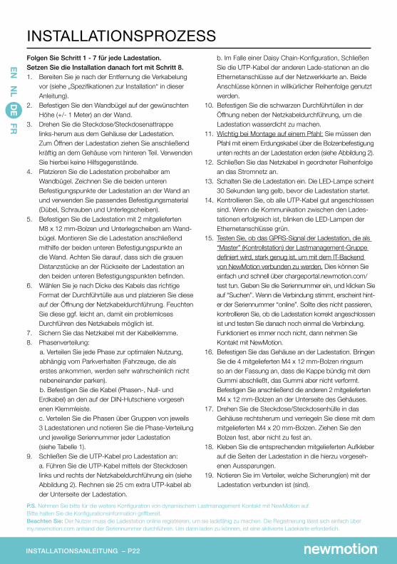
Folgen Sie Schritt 1 - 7 für jede Ladestation. Setzen Sie die Installation danach fort mit Schritt 8. 1. Bereiten Sie je nach der Entfernung die Verkabelung
vor (siehe „Spezifikationen zur Installation“ in dieser Anleitung).
2. Befestigen Sie den Wandbügel auf der gewünschten Höhe (+/- 1 Meter) an der Wand.
3. Drehen Sie die Steckdose/Steckdosenattrappe links-herum aus dem Gehäuse der Ladestation. Zum Öffnen der Ladestation ziehen Sie anschließend kräftig an dem Gehäuse vom hinteren Teil. Verwenden Sie hierbei keine Hilfsgegenstände.
4. Platzieren Sie die Ladestation probehalber am Wandbügel. Zeichnen Sie die beiden unteren Befestigungspunkte der Ladestation an der Wand an und verwenden Sie passendes Befestigungsmaterial (Dübel, Schrauben und Unterlegscheiben).
5. Befestigen Sie die Ladestation mit 2 mitgelieferten M8 x 12 mm-Bolzen und Unterlegscheiben am Wand-bügel. Montieren Sie die Ladestation anschließend mithilfe der beiden unteren Befestigungspunkte an die Wand. Achten Sie darauf, dass sich die grauen Distanzstücke an der Rückseite der Ladestation an den beiden unteren Befestigungspunkten befinden.
6. Wählen Sie je nach Dicke des Kabels das richtige Format der Durchführtülle aus und platzieren Sie diese auf der Öffnung der Netzkabeldurchführung. Feuchten Sie diese ggf. leicht an, damit ein problemloses Durchführen des Netzkabels möglich ist.
7. Sichern Sie das Netzkabel mit der Kabelklemme.8. Phasenverteilung: a. Verteilen Sie jede Phase zur optimalen Nutzung, abhängig vom Parkverhalten (Fahrzeuge, die als erstes ankommen, werden sehr wahrscheinlich nicht nebeneinander parken). b. Befestigen Sie die Kabel (Phasen-, Null- und Erdkabel) an den auf der DIN-Hutschiene vorgeseh enen Klemmleiste. c. Verteilen Sie die Phasen über Gruppen von jeweils
3 Ladestationen und notieren Sie die Phase-Verteilung und jeweilige Seriennummer jeder Ladestation (siehe Tabelle 1).
9. Schließen Sie die UTP-Kabel pro Ladestation an: a. Führen Sie die UTP-Kabel mittels der Steckdosen
links und rechts der Netzkabeldurchführung ein (siehe Abbildung 2). Rechnen sie 25 cm extra UTP-kabel ab der Unterseite der Ladestation.
b. Im Falle einer Daisy Chain-Konfiguration, Schließen Sie die UTP-Kabel der anderen Lade-stationen an die Ethernetanschlüsse auf der Netzwerkkarte an. Beide Anschlüsse können in willkürlicher Reihenfolge genutzt werden.
10. Befestigen Sie die schwarzen Durchführtüllen in der Öffnung neben der Netzkabeldurchführung, um die Ladestation wasserdicht zu machen.
11. Wichtig bei Montage auf einem Pfahl: Sie müssen den Pfahl mit einem Erdungskabel über die Bolzenbefestigung unten rechts an der Ladestation erden (siehe Abbildung 2).
12. Schließen Sie das Netzkabel in geordneter Reihenfolge an das Stromnetz an.
13. Schalten Sie die Ladestation ein. Die LED-Lampe scheint 30 Sekunden lang gelb, bevor die Ladestation startet.
14. Kontrollieren Sie, ob alle UTP-Kabel gut angeschlossen sind. Wenn die Kommunikation zwischen den Lades-tationen erfolgreich ist, blinken die LED-Lampen der Ethernetanschlüsse grün.
15. Testen Sie, ob das GPRS-Signal der Ladestation, die als “Master” (Kontrollstation) der Lastmanagement-Gruppe definiert wird, stark genug ist, um mit dem IT-Backend von NewMotion verbunden zu werden. Dies können Sie einfach und schnell über chargeportal.newmotion.com/test tun. Geben Sie die Seriennummer ein, und klicken Sie auf “Suchen”. Wenn die Verbindung stimmt, erscheint hint-er der Seriennummer “online”. Sollte dies nicht passieren, kontrollieren Sie, ob die Ladestation korrekt angeschlossen ist und testen Sie danach noch einmal die Verbindung. Funktioniert es immer noch nicht, dann nehmen Sie Kontakt mit NewMotion.
16. Befestigen Sie das Gehäuse an der Ladestation. Bringen Sie die 4 mitgelieferten M4 x 12 mm-Bolzen ringsum so an der Fassung an, dass die Kappe bündig mit dem Gummi abschließt, das Gummi aber nicht verformt. Befestigen Sie anschließend die anderen 2 mitgelieferten M4 x 12 mm-Bolzen an der Unterseite des Gehäuses.
17. Drehen Sie die Steckdose/Steckdosenhülle in das Gehäuse rechtsherum und verriegeln Sie diese mit dem mitgelieferten M4 x 20 mm-Bolzen. Ziehen Sie den Bolzen fest, aber nicht zu fest an.
18. Kleben Sie die entsprechenden mitgelieferten Aufkleber auf die Seiten der Ladestation in die hierzu vorgeseh-enen Aussparungen.
19. Notieren Sie im Verteiler, welche Sicherung(en) mit der Ladestation verbunden ist (sind).
P.S. Nehmen Sie bitte für die weitere Konfiguration von dynamischem Lastmanagement Kontakt mit NewMotion auf. Bitte halten Sie die Konfigurationsinformation griffbereit. Beachten Sie: Der Nutzer muss die Ladestation online registrieren, um sie ladefähig zu machen. Die Registrierung lässt sich einfach über my.newmotion.com anhand der Seriennummer durchführen. Um dann laden zu können, ist eine aktivierte Ladekarte erforderlich.
EN N
L DE FR
INSTALLATIONSPROZESS
INSTALLATIONSANLEITUNG – P23
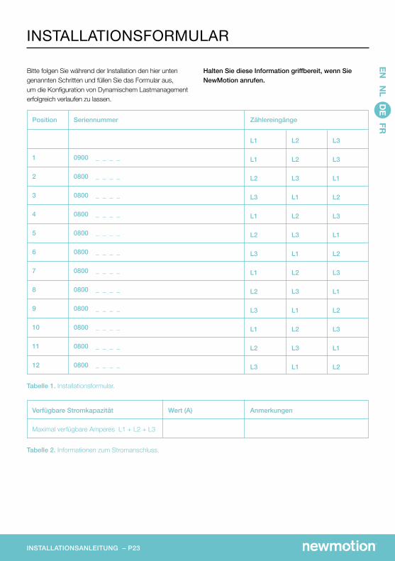
Tabelle 2. Informationen zum Stromanschluss.
Verfügbare Stromkapazität
Maximal verfügbare Amperes L1 + L2 + L3
AnmerkungenWert (A)
Bitte folgen Sie während der Installation den hier unten genannten Schritten und füllen Sie das Formular aus, um die Konfiguration von Dynamischem Lastmanagement erfolgreich verlaufen zu lassen.
Halten Sie diese Information griffbereit, wenn Sie NewMotion anrufen.
Tabelle 1. Installationsformular.
Position
1
2
3
4
5
6
7
8
9
10
11
12
Seriennummer
0900 _ _ _ _
0800 _ _ _ _
0800 _ _ _ _
0800 _ _ _ _
0800 _ _ _ _
0800 _ _ _ _
0800 _ _ _ _
0800 _ _ _ _
0800 _ _ _ _
0800 _ _ _ _
0800 _ _ _ _
0800 _ _ _ _
Zählereingänge
L1
L1
L2
L3
L1
L2
L3
L1
L2
L3
L1
L2
L3
L2
L2
L3
L1
L2
L3
L1
L2
L3
L1
L2
L3
L1
L3
L3
L1
L2
L3
L1
L2
L3
L1
L2
L3
L1
L2
EN N
L DE FR
INSTALLATIONSFORMULAR
MANUEL D’INSTALLATION – P25
EN N
L DE FR
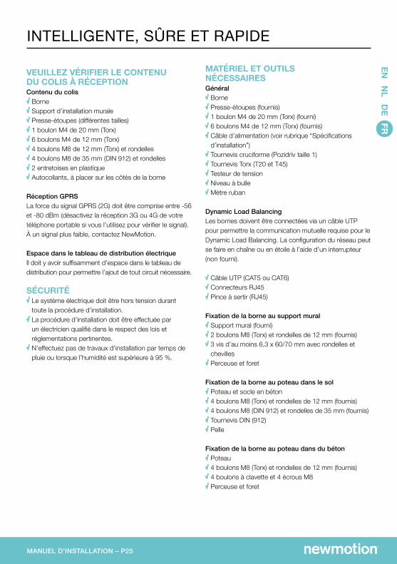
VEUILLEZ VÉRIFIER LE CONTENU DU COLIS À RÉCEPTIONContenu du colis Borne Support d’installation murale Presse-étoupes (différentes tailles) 1 boulon M4 de 20 mm (Torx) 6 boulons M4 de 12 mm (Torx) 4 boulons M8 de 12 mm (Torx) et rondelles 4 boulons M8 de 35 mm (DIN 912) et rondelles 2 entretoises en plastique Autocollants, à placer sur les côtés de la borne
Réception GPRSLa force du signal GPRS (2G) doit être comprise entre -56 et -80 dBm (désactivez la réception 3G ou 4G de votre téléphone portable si vous l’utilisez pour vérifier le signal). À un signal plus faible, contactez NewMotion.
Espace dans le tableau de distribution électriqueIl doit y avoir suffisamment d’espace dans le tableau de distribution pour permettre l’ajout de tout circuit nécessaire.
SÉCURITÉ Le système électrique doit être hors tension durant toute la procédure d’installation. La procédure d’installation doit être effectuée par un électricien qualifié dans le respect des lois et réglementations pertinentes. N’effectuez pas de travaux d’installation par temps de pluie ou lorsque l’humidité est supérieure à 95 %.
MATÉRIEL ET OUTILS NÉCESSAIRESGénéral Borne Presse-étoupes (fournis) 1 boulon M4 de 20 mm (Torx) (fourni) 6 boulons M4 de 12 mm (Torx) (fournis) Câble d’alimentation (voir rubrique “Spécifications d’installation”) Tournevis cruciforme (Pozidriv taille 1) Tournevis Torx (T20 et T45) Testeur de tension Niveau à bulle Mètre ruban
Dynamic Load BalancingLes bornes doivent être connectées via un câble UTP pour permettre la communication mutuelle requise pour le Dynamic Load Balancing. La configuration du réseau peut se faire en chaîne ou en étoile à l’aide d’un interrupteur (non fourni).
Câble UTP (CAT5 ou CAT6) Connecteurs RJ45 Pince à sertir (RJ45)
Fixation de la borne au support mural Support mural (fourni) 2 boulons M8 (Torx) et rondelles de 12 mm (fournis) 3 vis d’au moins 6,3 x 60/70 mm avec rondelles et chevilles Perceuse et foret
Fixation de la borne au poteau dans le sol Poteau et socle en béton 4 boulons M8 (Torx) et rondelles de 12 mm (fournis) 4 boulons M8 (DIN 912) et rondelles de 35 mm (fournis) Tournevis DIN (912) Pelle
Fixation de la borne au poteau dans du béton Poteau 4 boulons M8 (Torx) et rondelles de 12 mm (fournis) 4 boulons à clavette et 4 écrous M8 Perceuse et foret
INTELLIGENTE, SÛRE ET RAPIDE
MANUEL D’INSTALLATION – P26
Triphasé11 - 22 kW
Disjoncteur différentiel (RCD) triphasé
Câble d’alimentation au-dessus du sol
Câble d’alimentation souterrain
Fixation du câble
Dynamic Load Balancing
30mA Type B, ou 30 mA Type A associé avec un équipement approprié qui garantit un arrêt en cas de présence de la composante de courant continu de plus de 6mA.
Câble non armé isolé XLPE et gainé PVC
Câble armé isolé XLPE et gainé PVC
Tube PVC avec supports de serrage et appuis
Câble UTP standard CAT5 ou CAT6 avec connecteur RJ45
* Le câblage doit toujours être effectué de façon à assurer l’intensité matérielle maximale en condition de charge continue. Le dimensionnement des câbles est fourni à titre indicatif. NewMotion recommande de toujours utiliser une taille supérieure. Il incombe à l’électricien de sélectionner l’épaisseur de câble appropriée à chaque situation.
** L’électricien doit sélectionner un disjoncteur différentiel miniature correspondant au réglage d’intensité maximale de la borne.
Attention !La borne de recharge est reliée au réseau électrique. Même lorsque l’appareil est débranché, une tension électrique dangereuse peut être présente sur les bornes d’entrée. Avant de procéder à l’entretien, veillez à toujours débrancherl’alimentation de courant alternatif. Les instructions de sécurité sont conçues pour garantir une installation et une utilisation correcte. Le non-respect des instructions ou dispositions de sécurité figurant dans le présent manuel d’installationpeut entraîner un incendie, une électrocution ou de graves blessures. La borne de recharge est un produit appartenant à la classe de sécurité 1 et est fournie avec un conducteur de mise à la terre à des fins de sécurité. Les bornes d’entrée du courant alternatif doivent être munies d’une mise à la terre sans coupure à titre de sécurité. Assurez-vous que les câbles de branchement sont munis de fusibles et de coupe-circuits. Ne remplacez jamais un composant de sécurité par un composant de type différent. Veuillez consulter le manuel d’installation pour trouver le composant adéquat. Avant d’activer la borne, veuillez contrôler que la source électrique correspond aux paramètres de configuration du produit, comme décrit dans le manuel. Il est interdit d’utiliser une rallonge pour allonger le câble de charge.
MANUEL D’INSTALLATION – P27
Avertissement : ce document ne se substitue pas aux connaissances spécialisées de l’électricien qui doit veiller à effectuer l’installation en toute sécurité et conformément aux lois et réglementations pertinentes. Les électriciens sont en tout temps responsables de leur propre sécurité et de celle d’autrui. Si l’installation n’est pas réalisée conformément aux présentes instructions, l’électricien est responsable de tout dommage découlant directement ou indirectement de l’installation.
Capacité de charge maximale
Catégorie de sécurité électrique
Code IK (robustesse)
Dimensions
Poids
Coloris standard
Conception conforme aux normes
Branchement secteur
Mesure de kWh
Interface utilisateur/identification
Communication
Indice de protection
Température de fonctionnement
Humidité
Triphasé 32 A (22 kW)
Catégorie 1
IK10
503.5 x 200 x 137 mm
4.0 kg
Face arrière RAL 7031 (gris)Face avant RAL 9010 (blanc)
IEC61851-1IEC61851-22Exigences de la norme ZE-Ready 1.2
16 A à 32 A, 400 V (triphasé), 50 Hz
Certifiée conforme à la norme MID (pour la facturation)
RFID (NFC) Mifare 13.56 MHzIEC 14443AIEC 14443B
GPRS 2G (borne maître - unité de contrôle)Connection par ethernet GPRS 2/3/4G avec routeur mobile*
IP54 (pour usage intérieur et extérieur)
-30 °C á 50 °C
5 % à 95 %
SPÉCIFICATIONS TECHNIQUESEN
NL D
E FR
*Contactez NewMotion pour plus d’informations : +33 (0)9 77 55 43 49
MANUEL D’INSTALLATION – P28
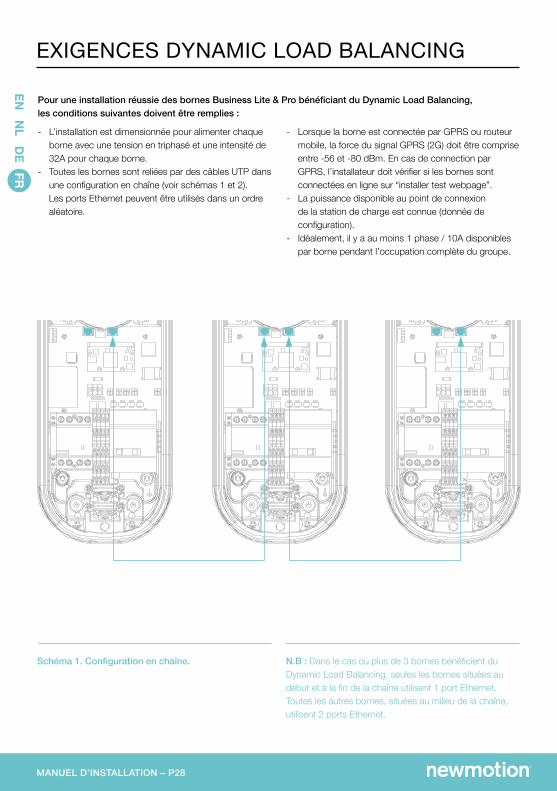
Schéma 1. Configuration en chaîne. N.B : Dans le cas où plus de 3 bornes bénéficient du Dynamic Load Balancing, seules les bornes situées au début et à la fin de la chaîne utilisent 1 port Ethernet. Toutes les autres bornes, situées au milieu de la chaîne, utilisent 2 ports Ethernet.
- Lorsque la borne est connectée par GPRS ou routeur mobile, la force du signal GPRS (2G) doit être comprise entre -56 et -80 dBm. En cas de connection par GPRS, l’installateur doit vérifier si les bornes sont connectées en ligne sur “installer test webpage”.
- La puissance disponible au point de connexion de la station de charge est connue (donnée de configuration).
- Idéalement, il y a au moins 1 phase / 10A disponibles par borne pendant l’occupation complète du groupe.
- L’installation est dimensionnée pour alimenter chaque borne avec une tension en triphasé et une intensité de 32A pour chaque borne.
- Toutes les bornes sont reliées par des câbles UTP dans une configuration en chaîne (voir schémas 1 et 2).
Les ports Ethernet peuvent être utilisés dans un ordre aléatoire.
Pour une installation réussie des bornes Business Lite & Pro bénéficiant du Dynamic Load Balancing, les conditions suivantes doivent être remplies :
EXIGENCES DYNAMIC LOAD BALANCING
EN N
L DE FR
AA
BB
CC
DD
EE
FF
8 8
7 7
6 6
5 5
4 4
3 3
2 2
1 1
DRA
WN
CH
K'D
APPV
'D
MFG
Q.A
UN
LESS OTH
ERWISE SPEC
IFIED:
DIM
ENSIO
NS A
RE IN M
ILLIMETERS
SURFA
CE FIN
ISH:
TOLERA
NC
ES: LIN
EAR:
AN
GU
LAR:
FINISH
:D
EBURR A
ND
BREA
K SHA
RP ED
GES
NA
ME
SIGN
ATU
RED
ATE
MA
TERIAL:
DO
NO
T SCA
LE DRA
WIN
GREV
ISION
TITLE:
DW
G N
O.
SCA
LE:1:5SH
EET 1 OF 1
A3
WEIG
HT:
Business PRO
MANUEL D’INSTALLATION – P29
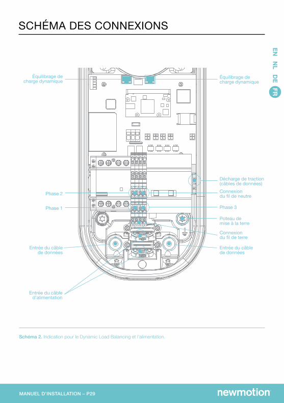
Schéma 2. Indication pour le Dynamic Load Balancing et l’alimentation.
SCHÉMA DES CONNEXIONSEN
NL D
E FR
AA
BB
CC
DD
EE
FF
8 8
7 7
6 6
5 5
4 4
3 3
2 2
1 1
DRA
WN
CH
K'D
APPV
'D
MFG
Q.A
UN
LESS OTH
ERWISE SPEC
IFIED:
DIM
ENSIO
NS A
RE IN M
ILLIMETERS
SURFA
CE FIN
ISH:
TOLERA
NC
ES: LIN
EAR:
AN
GU
LAR:
FINISH
:D
EBURR A
ND
BREA
K SHA
RP ED
GES
NA
ME
SIGN
ATU
RED
ATE
MA
TERIAL:
DO
NO
T SCA
LE DRA
WIN
GREV
ISION
TITLE:
DW
G N
O.
SCA
LE:1:5SH
EET 1 OF 1
A3
WEIG
HT:
Business PRO
Équilibrage de charge dynamique
Équilibrage de charge dynamique
Décharge de traction(câbles de données)Connexion du fil de neutre
Phase 3
Poteau demise à la terre
Entrée du câble de données
Entrée du câble de données
Phase 2
Phase 1
Connexion du fil de terre
Entrée du câbled’alimentation
MANUEL D’INSTALLATION – P30
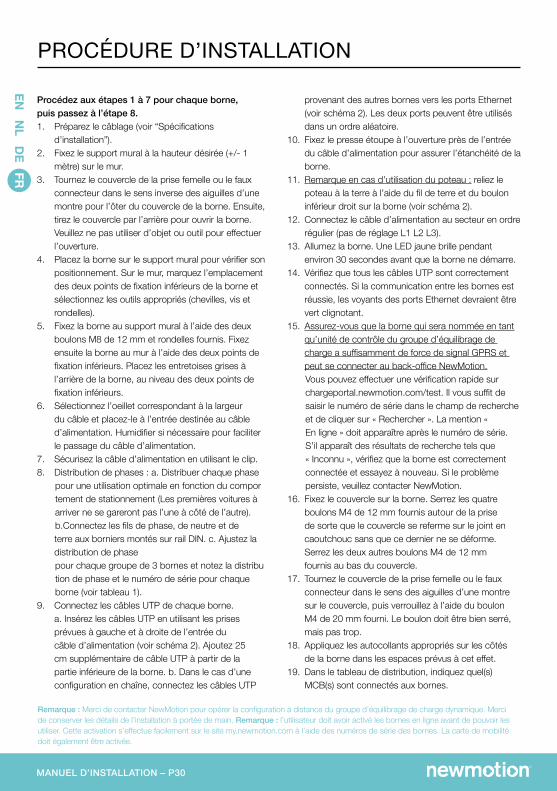
Procédez aux étapes 1 à 7 pour chaque borne, puis passez à l’étape 8. 1. Préparez le câblage (voir “Spécifications
d’installation”).2. Fixez le support mural à la hauteur désirée (+/- 1
mètre) sur le mur.3. Tournez le couvercle de la prise femelle ou le faux
connecteur dans le sens inverse des aiguilles d’une montre pour l’ôter du couvercle de la borne. Ensuite, tirez le couvercle par l’arrière pour ouvrir la borne. Veuillez ne pas utiliser d’objet ou outil pour effectuer l’ouverture.
4. Placez la borne sur le support mural pour vérifier son positionnement. Sur le mur, marquez l’emplacement des deux points de fixation inférieurs de la borne et sélectionnez les outils appropriés (chevilles, vis et rondelles).
5. Fixez la borne au support mural à l’aide des deux boulons M8 de 12 mm et rondelles fournis. Fixez ensuite la borne au mur à l’aide des deux points de fixation inférieurs. Placez les entretoises grises à l’arrière de la borne, au niveau des deux points de fixation inférieurs.
6. Sélectionnez l’oeillet correspondant à la largeur du câble et placez-le à l’entrée destinée au câble d’alimentation. Humidifier si nécessaire pour faciliter le passage du câble d’alimentation.
7. Sécurisez la câble d’alimentation en utilisant le clip.8. Distribution de phases : a. Distribuer chaque phase pour une utilisation optimale en fonction du compor tement de stationnement (Les premières voitures à arriver ne se gareront pas l’une à côté de l’autre). b.Connectez les fils de phase, de neutre et de terre aux borniers montés sur rail DIN. c. Ajustez la distribution de phase pour chaque groupe de 3 bornes et notez la distribu tion de phase et le numéro de série pour chaque borne (voir tableau 1).9. Connectez les câbles UTP de chaque borne. a. Insérez les câbles UTP en utilisant les prises
prévues à gauche et à droite de l’entrée du câble d’alimentation (voir schéma 2). Ajoutez 25 cm supplémentaire de câble UTP à partir de la partie inférieure de la borne. b. Dans le cas d’une configuration en chaîne, connectez les câbles UTP
provenant des autres bornes vers les ports Ethernet (voir schéma 2). Les deux ports peuvent être utilisés dans un ordre aléatoire.
10. Fixez le presse étoupe à l’ouverture près de l’entrée du câble d’alimentation pour assurer l’étanchéité de la borne.
11. Remarque en cas d’utilisation du poteau : reliez le poteau à la terre à l’aide du fil de terre et du boulon inférieur droit sur la borne (voir schéma 2).
12. Connectez le câble d’alimentation au secteur en ordre régulier (pas de réglage L1 L2 L3).
13. Allumez la borne. Une LED jaune brille pendant environ 30 secondes avant que la borne ne démarre.
14. Vérifiez que tous les câbles UTP sont correctement connectés. Si la communication entre les bornes est réussie, les voyants des ports Ethernet devraient être vert clignotant.
15. Assurez-vous que la borne qui sera nommée en tant qu’unité de contrôle du groupe d’équilibrage de charge a suffisamment de force de signal GPRS et peut se connecter au back-office NewMotion.
Vous pouvez effectuer une vérification rapide sur chargeportal.newmotion.com/test. Il vous suffit de saisir le numéro de série dans le champ de recherche et de cliquer sur « Rechercher ». La mention « En ligne » doit apparaître après le numéro de série. S’il apparaît des résultats de recherche tels que « Inconnu », vérifiez que la borne est correctement connectée et essayez à nouveau. Si le problème persiste, veuillez contacter NewMotion.16. Fixez le couvercle sur la borne. Serrez les quatre
boulons M4 de 12 mm fournis autour de la prise de sorte que le couvercle se referme sur le joint en caoutchouc sans que ce dernier ne se déforme. Serrez les deux autres boulons M4 de 12 mm fournis au bas du couvercle.
17. Tournez le couvercle de la prise femelle ou le faux connecteur dans le sens des aiguilles d’une montre sur le couvercle, puis verrouillez à l’aide du boulon M4 de 20 mm fourni. Le boulon doit être bien serré, mais pas trop.
18. Appliquez les autocollants appropriés sur les côtés de la borne dans les espaces prévus à cet effet.
19. Dans le tableau de distribution, indiquez quel(s) MCB(s) sont connectés aux bornes.
Remarque : Merci de contacter NewMotion pour opérer la configuration à distance du groupe d’équilibrage de charge dynamique. Merci de conserver les détails de l’installation à portée de main. Remarque : l’utilisateur doit avoir activé les bornes en ligne avant de pouvoir les utiliser. Cette activation s’effectue facilement sur le site my.newmotion.com à l’aide des numéros de série des bornes. La carte de mobilité doit également être activée.
PROCÉDURE D’INSTALLATION
EN N
L DE FR
MANUEL D’INSTALLATION – P31
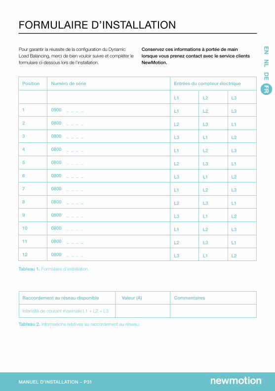
Tableau 2. Informations relatives au raccordement au réseau.
Raccordement au réseau disponible
Intensité de courant maximale L1 + L2 + L3
CommentairesValeur (A)
Pour garantir la réussite de la configuration du Dynamic Load Balancing, merci de bien vouloir suivre et compléter le formulaire ci-dessous lors de l’installation.
Conservez ces informations à portée de main lorsque vous prenez contact avec le service clients NewMotion.