182
Business Practice Manual for Metering Version 89 Last Revised: January 3, 2014 Formatted: Highlight Comment [DS1]: Davies: flagging revision date to be updated

Business Practice Manual for
Metering
Version 89
Last Revised: January 3, 2014
Formatted: Highlight
Comment [DS1]: Davies: flagging revision date to be updated

CAISO Business Practice Manual BPM for Metering
Version 8 January 3, 2014 Page 1
Approval History Approval Date: August 2, 2013
Effective Date: January 3, 2014
BPM Owner: Benik DerGevorgian and Gary DeShazo
BPM Owner’s Title: Director, Market Services and Director, Operations Engineering
Revision History
Version Date Description
Version 2 November 2, 2009
PRR 079 Metering BPM
BPM update to reflect Payment Acceleration implementation
Version 3 August 10, 2010
BPM changes to further clarify Payment Acceleration language and incorporate Proxy Demand Resource implementation
PRR 173 Metering BPM
Version 4 April 1, 2011 BPM changes to Section 12 Proxy Demand Resource.
Includes registration process clarification including the ability to register “pseudo locations” and additional language to clarify PDR minimum load reduction requirements.
BPM changes to Sections
Changes revenue metering business practice for participating generators that are distribution connected resources (DCR), also referred to as distributed generation (DG). In particular, the changes modify the methodology used in determining the correction factor, attributed to losses and credits incurred to virtually meter at the CAISO Point of Receipt (POR), and how it is applied to CAISO metered entities revenue meters.
Version 5 June 30, 2011 BPM changes to Section 12 Proxy Demand Resource to include Reliability Demand Response Resource program – Tariff effective 4/1/12. Credit Reform (FERC 741) and Settlement Timeline Change Process (SPTC) Changes - various sections
Version 6 May 7, 2012 PRR 543: Removal of RDRRfrom Metering BPM PRR 544: Revision to the Scheduling Coordinator Self-Audit Report
Formatted: Highlight
Comment [DS2]: flaggin revisions dates
CAISO Business Practice Manual BPM for Metering
Version 8 January 3, 2014 Page 2
Version Date Description BPM changes to Section 12 to remove the Reliability Demand Response Resource program. Changes to the guidelines provided for the SC Self Audit process.
Version 7 October 1, 2013
BPM changes to Section 3 Remove the references to provisional Certificate of Compliance in order to synchronize with the tariff
BPM changes to Section 3
Align the BPM with the recent changes to the CAISO Authorized Inspector Agreements and associated documents
BPM changes to Attachment D
Clarify the Validation, Estimation, and Editing (VEE) options used in the current CAISO Settlement Quality Meter Data System (SQMDS)
Version 8 January 3, 2014
BPM changes to Section 8 Remove the reference to “temporary exemptions” to match procedures used by the CAISO.
BPM changes to Section 8
Provide additional details about the updated Metering Exemptions from Compliance process currently used by the CAISO.
BPM changes to Attachment B
Remove references to worksheets that are no longer provided by the CAISO.
Various grammatical and spacing errors corrected throughout document.
Version 9 January 17, 2014
BPM changes to Section 12 Proxy Demand Resource to include Reliability Demand Response Resource program – Tariff effective 4/1/14. Added Direct Telemetry to the table in Section 12.1 per the market participant.
Formatted: Highlight
Comment [DS3]: update to reflect final

CAISO Business Practice Manual BPM for Metering
Version 8 January 3, 2014 Page 3
TABLE OF CONTENTS
1. Introduction .......................................................................................................................... 8
1.1 Purpose of California ISO Business Practice Manuals ................................................. 8
1.2 Purpose of this Business Practice Manual ................................................................... 9
1.3 References ................................................................................................................... 9
2. Overview of Metering CAISO ............................................................................................ 10
2.1 Metering Process ........................................................................................................ 10
2.2 Installation & Certification of Meters ........................................................................... 10
2.3 Overview of Flow of Meter Data ................................................................................. 11
2.4 Organization of BPM .................................................................................................. 12
3. CAISO Responsibilities ..................................................................................................... 13
3.1 Overview of CAISO Responsibilities .......................................................................... 13
3.2 Meter Certification ...................................................................................................... 13
3.2.1 Overview of Meter Installation Certification Process ...................................... 14
3.2.2 CAISO Certification Responsibilities ............................................................... 14
3.2.3 CAISO Metered Entities Certification Responsibilities .................................... 15
3.2.4 Scheduling Coordinator Metered Entities Certification Responsibilities ......... 21
3.3 CAISO Authority to Require Additional Metering Facilities ......................................... 21
3.3.1 Requirement to Install ..................................................................................... 22
3.3.2 Obligations of CAISO Metered Entity ............................................................. 22
3.3.3 CAISO Metered Entity Election to Install Additional Metering ........................ 22
3.4 Revenue Meter Data Acquisition & Processing System ............................................. 23
3.5 Failure of CAISO Facilities or Systems ...................................................................... 23
3.6 Audit & Testing ........................................................................................................... 24
3.7 Meter Data Retention ................................................................................................. 24
4. Common CAISO Metered Entity & Scheduling Coordinator Metered Entity Responsibilities ................................................................................................................. 25
4.1 Netting ........................................................................................................................ 25
4.1.1 Permitted ........................................................................................................ 25
4.1.2 Prohibited ........................................................................................................ 25
4.2 Accurate Meter Data ................................................................................................... 26
4.3 Meter Data Intervals ................................................................................................... 26
5. CAISO Metered Entity Responsibilities ........................................................................... 27

CAISO Business Practice Manual BPM for Metering
Version 8 January 3, 2014 Page 4
5.1 Revenue Quality Meter Data ...................................................................................... 27
5.1.1 Revenue Metering at the Point of Receipt (POR) ........................................... 27
5.1.2 Format & Collection of Meter Data ................................................................. 28
5.1.3 Access to Settlement Quality Meter Data ....................................................... 28
5.1.4 Maintenance & Repairs .................................................................................. 29
5.1.5 Meter Site Security ......................................................................................... 30
5.2 Certification of Metering Facilities ............................................................................... 30
5.3 Telecommunication Requirements ............................................................................. 30
6. Scheduling Coordinators for Scheduling Coordinator Metered Entity Responsibilities32
6.1 Provision of Settlement Quality Meter Data ................................................................ 32
6.1.1 Settlement Quality Meter Data Submission Format & Timing ........................ 33
6.1.2 Access to Settlement Quality Meter Data Systems ........................................ 37
6.1.3 Process for Submittal & Resubmittal of Settlement Quality Meter Data ......... 37
6.1.4 Failure to Submit Accurate Settlement Quality Meter Data (Actual, Estimated)38
6.2 Certification of Meters ................................................................................................. 38
6.3 Audit & Testing ........................................................................................................... 38
6.3.1 Scheduling Coordinator Self-Audit Report ...................................................... 38
6.3.2 Audit & Testing by CAISO .............................................................................. 40
7. Meter Service Agreements ................................................................................................ 41
7.1 CAISO Metered Entities ............................................................................................. 41
7.2 Scheduling Coordinator Metered Entities ................................................................... 41
7.3 Scheduling Coordinator Agreement ........................................................................... 42
7.4 Qualifying Facility Participating Generator Agreement ............................................... 42
8. Exemptions ......................................................................................................................... 43
8.1 Guidelines ................................................................................................................... 43
8.1.1 Publication of Guidelines ................................................................................ 43
8.1.2 Metering Exemption Publication ..................................................................... 44
8.2 Request for Exemption Procedure ............................................................................. 44
8.3 Permitted Exemptions ................................................................................................ 45
8.3.1 Exemptions from Providing Meter Data Directly to RMDAPS ......................... 45
8.3.2 Exemptions from Meter Standards ................................................................. 45
9. Other Metering Configurations ......................................................................................... 46
9.1 Metered Subsystems .................................................................................................. 46
CAISO Business Practice Manual BPM for Metering
Version 8 January 3, 2014 Page 5
9.2 Dynamic System Resource Meters ............................................................................ 47
9.3 Metering for Separate UFE Calculations .................................................................... 47
9.4 Metering for Participating Load Program .................................................................... 47
10. Station Power Program ..................................................................................................... 48
10.1 Station Power Program Overview .............................................................................. 48
10.2 Eligibility ...................................................................................................................... 49
10.3 Limitations .................................................................................................................. 49
10.4 Applications to Self-Supply Station Power ................................................................. 49
10.5 CAISO Monitoring & Review ...................................................................................... 50
10.6 Self-Supply Verification & CAISO Charges ................................................................ 51
10.7 Station Power Portfolio Set-Up ................................................................................... 52
10.8 Provision of Data to UDC or MSS Operator ............................................................... 53
11. Qualifying Facility (QF) Metering ...................................................................................... 54
11.1 Inapplicability of CAISO Metering Requirements to Regulatory Must-Take Generation54
11.2 QF Eligibility for Net Metering ..................................................................................... 54
11.2.1 Demonstration of QF Status ........................................................................... 54
11.2.2 Demonstration of Standby Service or Curtailment of Self-Provided Load ...... 55
11.2.3 Execution of a QF PGA .................................................................................. 55
11.3 Permitted Netting for Net Scheduled QFs .................................................................. 55
12. Proxy Demand Resources (PDR) and Reliability Demand Response Resources (RDRR) .......................................................................................................................... 12-56
12.1 Proxy Demand Resource Product Overview ......................................................... 12-56
12.2 Proxy Demand Resource Registration Process Overview .................................... 12-59
12.3 Executing a Proxy Demand Resource Response Provider (DRP) Agreement (DRPA) and Demand Response System (DRS) Access ............................................. 12-60
12.3.1 Obtaining a DRP ID ................................................................................... 12-61
12.3.2 Use of a Certified Scheduling Coordinator
12.4 Demand Response System .................................................................................. 12-64
12.5 Proxy Demand Resource Registration .................................................................. 12-65
12.5.1 Applying for a PDR or RDRR Resource ID using the Demand Response System
Registration Process 12.5.2 Applying for a Custom Resource ID 12.5.3 Registration Levels 12.5.4 Information Required When Applying for a Resource ID 12.5.5 Option for Registration of a Pseudo Location
Formatted: Normal, Indent: Left: 0.2", Firstline: 0.5"
Formatted: Font: Arial
Formatted: Indent: First line: 0.3", SpaceAfter: 0 pt
Formatted: Font: 11 pt
Formatted: Normal, Indent: First line: 0.3"
Formatted: Font: 11 pt
Formatted: Font: 11 pt
Formatted: Font: 11 pt
Formatted: Font: 11 pt
Formatted: Font: Arial
CAISO Business Practice Manual BPM for Metering
Version 8 January 3, 2014 Page 6
12.6 Using the Demand Response System for PDR Meter Data Submission, Customer Baseline, and Demand Response Energy Measurements ............................. 12-80
12.6.1 Customer Baseline
12.6.2 Customer Baseline and Demand Response Energy Measurements – Demand Response System Calculations
12.7 PDR No Pay Dispatch Performance (meter before/after in 5 minute intervals) ..... 12-93
12.8 PDR Hourly Generation – Alternative Baseline for PDR Demand Response Energy Measurement ................................................................................................. 12-94
12.9 DRS Monitoring Process ....................................................................................... 12-95
12.10 Outages ................................................................................................................. 12-95
Attachment A: End Use Meter Standards ................................................................................. 1
Attachment B: Technical Specifications .................................................................................. 1
Attachment C: CAISO Authorized Inspector Initial Site Verification and Meter Test procedures ........................................................................................................................... 1
Attachment D: CAISO Data Validation, Estimation and Editing Procedures for Revenue Quality Meter Data (RQMD) ................................................................................................. 1
Attachment E: CAISO Audit of Certified Metering Facilities ................................................... 1
Attachment F: Station Power Reallocation Example ............................................................... 1
Attachment G: PDR and RDRR Baseline Calculation Example ............................................. 3
Formatted: Font: 11 pt
Formatted: Normal, Indent: First line: 0.3"
Formatted: Font: 11 pt
Formatted: Font: Arial

CAISO Business Practice Manual BPM for Metering
Version 8 January 3, 2014 Page 7
List of Exhibits:
Exhibit 1-1: CAISO BPMs ............................................................................................................. 8
Exhibit 2-1: Overview of Installation and Certification of Meters ................................................. 11
Exhibit 2-2: Overview of Meter Data Flow to obtain SQMD ........................................................ 12
Exhibit 3-1: Meter Installation Certification Process .................................................................... 14
Exhibit 6-1: Overview of Settlement Quality Meter Data Submittal Deadline. ............................. 36

CAISO Business Practice Manual BPM for Metering
Version 8 January 3, 2014 Page 8
1. Introduction
Welcome to CAISO BPM for Metering. In this Introduction you will find the following
information:
The purpose of CAISO BPMs
What you can expect from this CAISO BPM
Other CAISO BPMs or documents that provide related or additional information
1.1 Purpose of California ISO Business Practice Manuals
The Business Practice Manuals (BPMs) developed by CAISO are intended to contain
implementation detail, consistent with and supported by the CAISO Tariff, including:
instructions, rules, procedures, examples, and guidelines for the administration, operation,
planning, and accounting requirements of CAISO and the markets. Exhibit 1-1 lists CAISO
BPMs.
Exhibit 1-1: CAISO BPMs
Title
BPM for Market Operations
BPM for Market Instruments
BPM for Settlements & Billing
BPM for Scheduling Coordinator Certification and Termination
BPM for Congestion Revenue Rights
BPM for Candidate CRR Holder Registration
BPM for Managing Full Network Model
BPM for Rules of Conduct Administration
BPM for Outage Management
BPM for Metering
BPM for Reliability Requirements
BPM for Credit Management
BPM for Compliance Monitoring
BPM for Definitions & Acronyms
BPM for BPM Change Management
BPM for the Transmission Planning Process
CAISO Business Practice Manual BPM for Metering
Version 8 January 3, 2014 Page 9
1.2 Purpose of this Business Practice Manual
The BPM for Metering covers the metering responsibilities for the CAISO, CAISO Metered
Entities, Scheduling Coordinator (SC) Metered Entities, and Scheduling Coordinators
representing Metered Entities for the meter installation, certification and maintenance in addition
to the creation of Settlement Quality Meter Data (SQMD).
The provisions of this BPM are intended to be consistent with the CAISO Tariff. If the provisions
of this BPM nevertheless conflict with the CAISO Tariff, the CAISO is bound to operate in
accordance with the CAISO Tariff. Any provision of the CAISO Tariff that may have been
summarized or repeated in this BPM is only to aid understanding. Even though every effort will
be made by CAISO to update the information contained in this BPM and to notify Market
Participants of changes, it is the responsibility of each Market Participant to ensure that he or
she is using the most recent version of this BPM and to comply with all applicable provisions of
the CAISO Tariff.
A reference in this BPM to the CAISO Tariff, a given agreement, any other BPM or instrument,
is intended to refer to the CAISO Tariff, that agreement, BPM or instrument as modified,
amended, supplemented or restated.
The captions and headings in this BPM are intended solely to facilitate reference and not to
have any bearing on the meaning of any of the terms and conditions.
1.3 References
Other reference information related to this BPM includes:
The BPM for Rules of Conduct Administration
The BPM for Full Network Model
The BPM for Settlements and Billing

CAISO Business Practice Manual BPM for Metering
Version 8 January 3, 2014 Page 10
2. Overview of Metering CAISO
Welcome to the Overview of Metering section of the BPM for Metering. In this section you will
find the following information:
A description of the metering process
A diagram of the meter installation and certification process
A diagram of the flow of Meter Data
2.1 Metering Process
This BPM describes the process and procedures used by the CAISO, CAISO Metered Entities,
and Scheduling Coordinators for Scheduling Coordinator Metered Entities to obtain SQMD used
for the Settlement of the CAISO Markets. SQMD is used for billable quantities to represent the
Energy generated or consumed during a Settlement Interval. SQMD is obtained from two
different sources: CAISO Metered Entities (Meter Data directly polled by CAISO) and
Scheduling Coordinator Metered Entities (Meter Data submitted to CAISO by Scheduling
Coordinators). This BPM provides information regarding:
CAISO installation requirements of Metering Facilities
How the CAISO certifies Metering Facilities for CAISO Metered Entities and meters for
Scheduling Coordinator Metered Entities
Necessary agreements for participation in the CAISO Markets
How Meter Data is created and submitted by CAISO Metered Entities and Scheduling
Coordinators for Scheduling Coordinator Metered Entities
CAISO’s role in creating SQMD through Validation, Editing and Estimation (VEE)
Audit, testing, and maintenance requirements of Metering Facilities
2.2 Installation & Certification of Meters
Exhibit 2-1 illustrates the process for installation and certification of Metering Facilities for
CAISO Metered Entities and meters for Scheduling Coordinator Metered Entities.

CAISO Business Practice Manual BPM for Metering
Version 8 January 3, 2014 Page 11
Exhibit 2-1: Overview of Installation and Certification of Meters
2.3 Overview of Flow of Meter Data
Exhibit 2-2 illustrates the relationship between CAISO, CAISO Metered Entities, and Scheduling
Coordinator Metered Entities to obtain SQMD.
CAISO Metered Entity
Scheduling Coordinator for
Metered Entity (not CAISO Metered)
MSA CAISO ME
Meter Installation and Inspection
Certify Metering Facility
Establish Communication link between CAISO Metered Entity
and CAISO RMDAPS
Meter Certified by LRA or CAISO
Establish ability of SC to provide SQMD to SQMDS (Settlement
Quality Meter Data System)
Agreements
SC Agreement
MSA SC
Meter Design
Certify SC for SC Metered Entity

CAISO Business Practice Manual BPM for Metering
Version 8 January 3, 2014 Page 12
Exhibit 2-2: Overview of Meter Data Flow to obtain SQMD
2.4 Organization of BPM
The following Sections 3, 4, 5, and 6 describe the respective responsibilities of CAISO, CAISO
Metered Entities and Scheduling Coordinators for Scheduling Coordinator Metered Entities.
Sections 7 through 12 describe provisions for Meter Service Agreements, exemptions, other
metering configurations, Station Power metering, and metering for Qualifying Facilities and
Proxy Demand Resources.
RMDAPSCAISO Metered
Entity
Scheduling Coordinator for
SC Metered Entity
CAISO polls RevenueMeter Data
CAISO conducts VEE
CAISO publishesSQMD to SQMDS
5 Business days or best efforts
SC Submits Actual SQMD To SQMDS
T+48 Business days after trading day
Meter DataStored
Settlements and Billing Process
SC Submits SQMD to SQMDS at T + 8 B
(Actual or Estimated)

CAISO Business Practice Manual BPM for Metering
Version 8 January 3, 2014 Page 13
3. CAISO Responsibilities
Welcome to the CAISO Responsibilities section of the BPM for Metering. In this section you will
find the following information:
An overview of CAISO responsibilities
A description of the installation and certification process for Metering Facilities
A description of the Revenue Meter Data Acquisition and Processing System (RMDAPS)
system
A description of the procedure followed in the event of communication facility failures
A description of the auditing and testing requirements
A description of Meter Data retention policy of CAISO
3.1 Overview of CAISO Responsibilities
CAISO Tariff Section 10.1.1
The CAISO is responsible for establishing and maintaining the Revenue Meter Data Acquisition
and Processing System (RMDAPS) and the Settlement Quality Meter Data System (SQMDS).
RMDAPS acquires Revenue Quality Meter Data which is processed into SQMD (actual) for use
in the CAISO’s Settlement and billing process and SQMDS acquires Scheduling Coordinators’
Settlement Quality Meter Data (actual, estimated). The CAISO is also responsible for the
following for CAISO Metered Entities:
(a) setting standards and procedures for the registration, certification, auditing,
testing, and maintenance of revenue quality meters and
(b) establishing procedures for the collection, security, validation and estimation of
Meter Data
3.2 Meter Certification
CAISO has overall responsibility for certification. Some of this responsibility is accomplished by
the responsibilities placed on CAISO Metered Entities and Scheduling Coordinators for
Scheduling Coordinator Metered Entities. This Section 3.2 summarizes the respective
certification responsibilities of CAISO, CAISO Metered Entities and Scheduling Coordinators
with respect to Scheduling Coordinator Metered Entities.
CAISO Business Practice Manual BPM for Metering
Version 8 January 3, 2014 Page 14
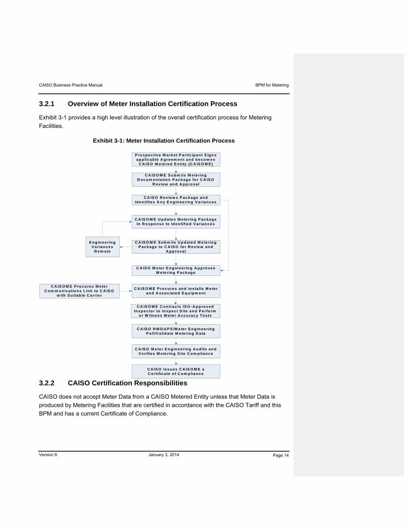
3.2.1 Overview of Meter Installation Certification Process
Exhibit 3-1 provides a high level illustration of the overall certification process for Metering
Facilities.
Exhibit 3-1: Meter Installation Certification Process
3.2.2 CAISO Certification Responsibilities
CAISO does not accept Meter Data from a CAISO Metered Entity unless that Meter Data is
produced by Metering Facilities that are certified in accordance with the CAISO Tariff and this
BPM and has a current Certificate of Compliance.
P ro sp ec tiv e M a rke t P artic ip a n t S ig n s ap p lica b le A g reem e n t an d b e co m e s
C A IS O M ete re d E n tity (C A IS O M E )
C A IS O M E S u b m its M ete rin g D o c u m e n ta tio n P a ck ag e fo r C A IS O
R ev iew an d A p p ro v a l
C A IS O R e v ie w s P ac ka g e an d Id e n tifie s A n y E n g in ee rin g V a ria n c es
C A IS O M E S u b m its U p d ate d M e te rin g P ac ka g e to C A IS O fo r R e v ie w an d
A p p ro va l
C A IS O M E U p d ate s M e te rin g P ac ka g e In R es p o n s e to Id e n tified V a ria n c es
C A IS O M e ter E n g in e erin g A p p ro ve s M eterin g P a ck ag e
E n g in ee rin g V arian ce s
R e m ain
C A IS O M E P ro c u res M e te r C o m m u n ic a tio n s L in k to C A IS O
w ith S u itab le C a rrie r
C A IS O M E P ro c u re s an d In s ta lls M e te r a n d A ss o c ia ted E q u ip m en t
C A IS O M E C o n tra c ts IS O -A p p ro ve d In s p e c to r to In sp ec t S ite an d P e rfo rm
o r W itn es s M e te r A cc u ra cy T es ts
C A IS O R M D A P S /M e te r E n g in eerin g P o ll/V a lid a te M e te rin g D a ta
C A IS O M eter E n g in e erin g A u d its an d V erifies M e te rin g S ite C o m p lia n c e
C A IS O Iss u es C A IS O M E a C e rtific a te o f C o m p lia n c e
CAISO Business Practice Manual BPM for Metering
Version 8 January 3, 2014 Page 15
CAISO does not accept SQMD relating to a Scheduling Coordinator Metered Entity unless it is
produced by Metering Facilities that are certified in accordance with:
The certification or similar criteria prescribed by the relevant Local Regulatory Authority
(LRA)1
If the Local Regulatory Authority has not prescribed any certification criteria for the
Metering Facilities, the certification criteria prescribed for CAISO Metered Entities by this
BPM apply.
As indicated below in Section 3.2.3, for the purpose of these certification requirements,
references to CAISO Metered Entities include the Scheduling Coordinators for the Scheduling
Coordinator Metered Entities where the certification requirements are not covered by the
certification requirements of a Local Regulatory Authority.
3.2.3 CAISO Metered Entities Certification Responsibilities
CAISO Metered Entities must use a certified meter, request and provide information for a
certified Metering Facility and have a CAISO Authorized Inspector review and inspect the
facility. CAISO has the final authority to settle accuracy disputes between the CAISO
Authorized Inspector and the Metering Facility.
3.2.3.1 End Use Meter Standards
All metering is of a revenue class metering accuracy in accordance with the ANSI C12
standards on metering and any other requirements of the relevant UDC or Local Regulatory
Authority that apply. Such requirements apply to meters, current transformers and potential
transformers, and associated wiring and equipment. End Use Meter Standards are located in
Attachment A of this BPM.
3.2.3.2 Certification Criteria
The criteria for certifying the Metering Facilities of CAISO Metered Entities include meeting the
requirements for installation, certification and establishment of communication equipment. All
requests made to CAISO to perform the certification of Metering Facilities must be made in
accordance with the Technical Specifications (Attachment B). If CAISO agrees to perform the
certification of Metering Facilities, CAISO and the CAISO Metered Entity must agree to the
1 CAISO may require Scheduling Coordinators to provide it with a copy of any certificate issued by the Local
Regulatory Authority in respect of the Metering Facilities of each SC Metered Entity they represent. The Scheduling Coordinator must provide to CAISO a copy of such certificate within five business days of receiving the request for the certificate from CAISO.
CAISO Business Practice Manual BPM for Metering
Version 8 January 3, 2014 Page 16
terms and conditions on which the CAISO undertakes the certification including the assistance
provided by the CAISO Metered Entity, the responsibility for costs and the indemnities provided.
3.2.3.3 Inspection by CAISO Authorized Inspectors
A CAISO Metered Entity seeking certification of its Metering Facilities independently engages a
CAISO Authorized Inspector to perform inspection of its Metering Facilities and requests the
CAISO to perform the certification of its Metering Facilities. It is the responsibility of the relevant
CAISO Metered Entity to ensure that any inspector it engages to undertake the inspection of its
Metering Facilities holds a current Authorized Inspector identification card issued by the CAISO,
which authorizes that inspector to carry out the duties of a CAISO Authorized Inspector. CAISO
Metered Entities must ensure that CAISO Authorized Inspectors performing an inspection of its
Metering Facilities have executed a Meter Inspector Certification Agreement with the CAISO.
CAISO Metered Entities must also ensure that neither the CAISO Authorized Inspector nor the
Inspection Company (including Affiliates) employing that CAISO Authorized Inspector may
certify any Metering Facilities: (i) it has directly owned or leased at any time; (ii) it has installed,
designed, or programmed; or (iii) in which it holds a current financial or ownership interest,
except for an employee pension or a holding of publicly traded securities. The CAISO publishes
on the CAISO Website, for informational purposes only, a list of the CAISO approved meter
inspection companies at:
http://www.caiso.com/market/Pages/MeteringTelemetry/Default.aspx
If a CAISO Metered Entity would like the CAISO to perform the inspection of its Metering
Facilities, the CAISO Metered Entity must submit a letter to the CAISO Manager of Operations
Support. The request letter must contain the following:
Specify the Metering Facilities to be certified
Provide the documentation referred to in Section 3.2.3.4 of this BPM
Detail the reasons why the CAISO Metered Entity cannot engage the services of a
CAISO Authorized Inspector to perform the inspection. An acceptable request must
include either, 1) information about the requesting entity’s contacts with no less than two
CAISO Authorized Inspectors and an explanation of why the requesting entity could not
contract with the CAISO Authorized Inspector or 2) a compelling explanation why it was
impossible or impractical for the requesting entity to make such contacts with two CAISO
Authorized Inspectors. [Note: Any such request could be available to the public under
the CAISO Information Availability Policy.]

CAISO Business Practice Manual BPM for Metering
Version 8 January 3, 2014 Page 17
The CAISO, within 14 days of receiving a request for it to inspect Metering Facilities, informs the
CAISO Metered Entity whether it undertakes the inspection or requires the CAISO Metered
Entity to engage a CAISO Authorized Inspector to perform the inspection. The site name of
approved locations will be posted on the CAISO Website.
3.2.3.4 Documentation Requirements
To initiate the Certification process Interconnection Customers shall follow the Resource
Interconnection process. The CAISO Metered Entity must provide the following information to
the CAISO and to the CAISO Authorized Inspector:
Schematics – The CAISO Metered Entity provides schematics of the metering
installation being considered for CAISO certification. Such drawings must be dated,
bear the current drawing revision number and show all wiring, connections and devices
in the circuits. Electrical Schematics must be issued for Construction (IFC) and
Professional Engineer (PE) Stamped.
Drawings required:
3 Line Drawing showing primary conductors, Revenue Metering Instrument
Transformers, and the secondary circuit including all meters, devices, and test
switches. This drawing shall indicate transformer polarities for both Current and
Voltage Transformers, with CT H1 polarity facing the CAISO Grid.
Detailed Station One Line depicts the generating unit(s) and/or load(s) connecting to
the CAISO Grid. This drawing shall show how generators, transformers and aux
transformers are connected, showing all breakers, disconnects, and CAISO Revenue
Metering to CAISO Point of Receipt (POR), where the CAISO POR differs from the
meter location.
Communication Block Diagram must show physical and logical connections from
CAISO Revenue Meter to CAISO RMDAPS, including IP addresses, ports, and
communications protocols.
The CAISO Metering Certification Form and corresponding Site Verification Data Sheet
located on CAISO Website at:
http://www.caiso.com/market/Pages/MeteringTelemetry/Default.aspx
Transformer and Line Loss Worksheets, where applicable.

CAISO Business Practice Manual BPM for Metering
Version 8 January 3, 2014 Page 18
Distribution Compensation Factor (DCF) engineering study (if applicable per BPM
section 5.1.1) with letter of agreement of DCF from appropriate UDC/Distribution
Company/ Interconnection entity.
Supplemental Documentation which may be required at CAISO discretion:
Map to the site
Contact personnel
System Description Overview: An overview should include a brief description one
page or less of the operation of the site. Examples would be the meter used and
how it communicates with the CAISO. The size of the Generating Unit and
associated Load should also be included. Other examples include the Point of
Delivery of Energy to the CAISO Controlled Grid and all relevant information about
current transformers and voltage transformers that include line and transformer loss
compensation. The operation of the meters input and output circuits.
3.2.3.5 Meter Facility Site Acceptance, Verification, & Meter Test
The CAISO Authorized Inspector must complete a CAISO approved Site Verification Data Sheet
in relation to each set of Metering Facilities that it inspects. The Site Verification Data Sheet is
posted on the CAISO Website at:
http://www.caiso.com/market/Pages/MeteringTelemetry/Default.aspx
The CAISO Authorized Inspector provides the most recent test results documenting instrument
calibration results by serial number and the traceable link to the National Institute for Science
and Technology (NIST).
Details of the CAISO Authorized Inspector site acceptance criteria include verification of:
Drawings and documentation
Meter and related component locations
Name plate data of instrument transformers
Name plate of Generating Unit, if applicable
Revenue meter calibration limits
Meter and related components, seals, and locks
Applied instrument transformer burdens
Applied metering constants
Communications

CAISO Business Practice Manual BPM for Metering
Version 8 January 3, 2014 Page 19
Metering compensation (including transformer losses, line losses and distribution
compensation factor, when applicable)
The CAISO Authorized Inspector also conducts a site verification and either performs or
witnesses the performance of accuracy tests for the Metering Facility installations. Details of
these verification steps can be found in Attachment C.
3.2.3.6 CAISO Review of Documentation
If there are any discrepancies between the CAISO certified drawings on file and the actual
metering circuitry inspected by the CAISO Authorized Inspector or CAISO, then the CAISO
requests that the owner or authorized owner representative document that discrepancy and
revise the schematic drawings provided to CAISO. Where the CAISO Authorized Inspector
discovers a discrepancy, they must notify CAISO and the CAISO Metered Entity of the
discrepancy within 24 hours of the discovery.
CAISO reviews all documentation provided to it by the CAISO Metered Entity and the site
verification form prepared by the CAISO Authorized Inspector. If CAISO finds the data is
incomplete or fails to meet the relevant standards referred to in the CAISO Tariff and this BPM,
the CAISO provides written notice of the deficiencies to the CAISO Metered Entity.
3.2.3.7 Certification Testing & Issuance of Certificate of Compliance
CAISO will either approve or reject a proposal for installation:
Approval – If the CAISO unconditionally approves a proposal for installation, it will notify
the CAISO Metered Entity that the proposal for installation has been approved. The
CAISO Metered Entity then begins installation of the Metering Facilities in accordance
with the proposal for installation.
Rejection – If the CAISO rejects a proposal for installation, it notifies the CAISO
Metered Entity that the proposal is rejected. The CAISO Metered Entity must submit
CAISO a revised proposal for installation within 14 Business Days of receiving the notice
of rejection. If the CAISO rejects for a second time a proposal for installation submitted
by a CAISO Metered Entity in respect to the same or similar notice issued by CAISO, the
CAISO and CAISO Metered Entity use all reasonable good faith efforts to reach
agreement on the requirements and disputed items and in the absence of agreement
either party may refer the dispute to an alternative dispute resolution process.

CAISO Business Practice Manual BPM for Metering
Version 8 January 3, 2014 Page 20
If CAISO finds that the certification process described above is complete, it initiates tests to
certify the RMDAPS interface with the relevant Metering Facilities (See Attachment C, Section
C4, Communications Circuit Test).
Upon successful completion of the RMDAPS interface test, CAISO issues a Certificate of
Compliance.
3.2.3.8 Metering Facility Maintenance
CAISO Metered Entities must ensure proper operation and integrity of the metering equipment.
The CAISO recommends CAISO Metered Entities test their Metering Facilities a minimum of
once every two years. To ensure that this standard is maintained, a site audit process by the
CAISO occurs periodically. The site audit is a review by CAISO of the Metering Facility data as
recorded as part of the Metering Facility certification and as documented in the most current
Site Verification Data Sheet on file at CAISO.
3.2.3.9 Revocation of Certificate of Compliance
CAISO may revoke in full or in part any Certificate of Compliance if:
It has reasonable grounds to believe that all or some of the Metering Facilities covered
by that Certificate of Compliance no longer meet the certification criteria for Metering
Facilities contained in the CAISO Tariff and this BPM.
It has given written notice to the relevant CAISO Metered Entity stating that it does not
believe that the identified Metering Facilities meet the certification criteria (including the
reasons for that belief) and that the CAISO Metered Entity fails to satisfy the CAISO,
within the time period specified in the CAISO’s notice, that the Metering Facilities meet
the certification criteria.
If the CAISO revokes in full or part a Certificate of Compliance, the relevant CAISO Metered
Entity may request recertification.
3.2.3.10 Modification of Metering Facilities
CAISO approval must be obtained before any modifications or changes are made to any
Metering Facilities of a CAISO Metered Entity that have been certified pursuant to the CAISO
Tariff or this BPM. The CAISO may, at its discretion, require those Metering Facilities to be
recertified.
CAISO Business Practice Manual BPM for Metering
Version 8 January 3, 2014 Page 21
3.2.4 Scheduling Coordinator Metered Entities Certification Responsibilities
Scheduling Coordinators for Scheduling Coordinator Metered Entities must ensure the metered
entities they represent have certified meters or must follow the certification process for CAISO
Metered Entities.
3.2.4.1 Local Regulatory Agency Certification Requirements
Scheduling Coordinators representing Scheduling Coordinator Metered Entities must ensure the
meters for their Scheduling Coordinator Metered Entities are certified in accordance with the
certification requirements of the appropriate Local Regulatory Authority (LRA). Scheduling
Coordinators are responsible for obtaining any necessary approval of the relevant Local
Regulatory Authority to its proposed security and VEE procedures. The CAISO does not
perform any VEE procedures on the actual or estimated Settlement Quality Meter Data it
receives from Scheduling Coordinators for Scheduling Coordinator Metered Entities.
3.2.4.2 No Local Regulatory Agency Certification Requirements
If the relevant Local Regulatory Authority has not prescribed any certification criteria for the
Metering Facilities of a Scheduling Coordinator Metered Entity, the Scheduling Coordinator
representing that Scheduling Coordinator Metered Entity must promptly notify the CAISO in
writing that no such criteria have been prescribed. That Scheduling Coordinator is then
responsible for ensuring that the Scheduling Coordinator Metered Entities it represents obtain
and maintain Certificates of Compliance in respect of all of the Metering Facilities of those
Scheduling Coordinator Metered Entities in accordance with this BPM. Scheduling
Coordinators must engage a CAISO Authorized Inspector to perform the certification of any
Metering Facilities that are certified under this BPM and otherwise follow the requirements of
Section 3.2.3 for CAISO Metered Entities.
3.3 CAISO Authority to Require Additional Metering Facilities
CAISO Tariff Section 10.2.14
CAISO has the authority under the CAISO Tariff to require a CAISO Metered Entity to install
Metering Facilities. In directing the addition of meters and metering system components that
would impose increased costs on a CAISO Metered Entity, CAISO will give due consideration to
whether the expected benefits of such equipment are sufficient to justify such increased costs.
A CAISO Metered Entity may not start installation of additional metering until CAISO has
approved its proposal for Installation.

CAISO Business Practice Manual BPM for Metering
Version 8 January 3, 2014 Page 22
3.3.1 Requirement to Install
If CAISO determines that there is a need to install additional Metering Facilities on the CAISO
Controlled Grid, it notifies the relevant CAISO Metered Entity of that need. The CAISO’s notice
to that CAISO Metered Entity will include:
Location of the meter point at which the additional Metering Facilities are required
Date by which the CAISO Metered Entity must install the relevant Metering Facility
The reason for the need to install the additional Metering Facilities
Any other information the CAISO considers relevant
3.3.2 Obligations of CAISO Metered Entity
A CAISO Metered Entity that is notified by CAISO that it is required to install additional Metering
Facilities must:
Give CAISO written confirmation of receipt of that notice within three Business Days of
receiving that notice
Submit a proposal for installation to CAISO within 45 Business Days of receiving that
notice. The proposal for installation must set out the following information:
A description of the proposed Metering Facilities to be installed (which includes
all relevant schematic drawings and one–line drawings)
A proposed timetable for the installation
Any other information requested by CAISO
3.3.3 CAISO Metered Entity Election to Install Additional Metering
A CAISO Metered Entity may choose to install additional metering, including Backup Meters. If
a CAISO Metered Entity installs such additional metering, such metering must, unless the
CAISO agrees otherwise:
Be installed and maintained at CAISO Metered Entity’s cost
Be located on CAISO Metered Entity’s side of any primary meter
Not interfere with the accuracy of any primary meter and, if that primary meter is directly
polled by CAISO, the CAISO’s ability to directly poll that meter

CAISO Business Practice Manual BPM for Metering
Version 8 January 3, 2014 Page 23
Any meter data produced by additional metering may be used by CAISO for Settlement and
billing purposes in the event of the failure, or during tests or repairs of, the primary meter
provided that the following conditions are all satisfied: (i) such additional metering has a current
Certificate of Compliance; (ii) the CAISO Metered Entity gives CAISO prior verbal notice that
such meter is used and the period for which it will be used; and (iii) if the primary meter is
directly polled by CAISO, that additional metering is capable of being directly polled by CAISO.
3.4 Revenue Meter Data Acquisition & Processing System
CAISO uses RMDAPS to read the CAISO Metered Entities’ meters on a daily basis. CAISO
also retrieves data from the meters that provides information on the health of the meter (i.e.,
error logs, back up battery status, etc.). CAISO is responsible for taking the raw unedited Meter
Data and performing the Validation, Estimation, and Editing (VEE) procedures to produce actual
Settlement Quality Meter Data. CAISO VEE procedures are contained in Attachment D.
In addition, VEE is conducted on individual meter reads that may be aggregated with other
meters to produce the specific resource ID SQMD. This includes Generating Unit resource IDs
that are made up of multiple Generating Units electrically connected at the same point or
Generating Units that are considered a Physical Scheduling Plant.
CAISO makes its best effort to read the CAISO Metered Entities’ meters and make the SQMD
available to the CAISO Metered Entities (and their Scheduling Coordinators) within five
Business Days. The Scheduling Coordinator or the CAISO Metered Entity can obtain their
Meter Data, by resource ID, from the SQMDS. The CAISO Metered Entities can verify and
monitor their data to assure the data is as expected.
Note that RMDAPS does not collect Meter Data for Scheduling Coordinator Metered Entities.
The Scheduling Coordinators for Scheduling Coordinator Metered Entities submit actual or
estimated Settlement Quality Meter Data directly into SQMDS.
3.5 Failure of CAISO Facilities or Systems
CAISO Tariff Section 10.1.6
In the event facility and/or system failure impacts the CAISO’s ability to accept, collect, and
process Revenue Quality Meter Data or Settlement Quality Meter Data, alternative measures
may be required by the CAISO, CAISO Metered Entities, and Scheduling Coordinator Metered
Entities.
These measures are communicated to the market via CAISO Market Notice.

CAISO Business Practice Manual BPM for Metering
Version 8 January 3, 2014 Page 24
3.6 Audit & Testing
CAISO Tariff Section 10.2.11
Certified CAISO Metered Entities are subject to CAISO Metering Facility audits, and testing.
CAISO has the right to either conduct any audit or test it considers necessary or to witness such
audit or test carried out by the CAISO Metered Entity. Details of the Metering Facility audits are
outlined in Attachment E.
The audit and testing requirements for Scheduling Coordinator Metered Entities, including the
self-audit requirements, are described in Section 6.3.
3.7 Meter Data Retention
CAISO Tariff Section 10.1.2
The CAISO maintains a record of all Revenue Quality Meter Data and Settlement Quality Meter
Data provided to it, as well as the Settlement Quality Meter Data it produces, for a period of 18
months on-site at CAISO’s facilities and for a period which, at least, allows for the re-run of data
as required by the CAISO Tariff and any adjustment rules of the Local Regulatory Authority
governing the Scheduling Coordinators and their End-Use Customers and FERC. The CAISO,
on reasonable notice, provides a Scheduling Coordinator with access to Settlement Quality
Meter Data (actual or Scheduling Coordinator estimated) provided that the Scheduling
Coordinator requesting access represented the entity for which that data was provided at the
time the data was provided to the CAISO.

CAISO Business Practice Manual BPM for Metering
Version 8 January 3, 2014 Page 25
4. Common CAISO Metered Entity & Scheduling Coordinator Metered Entity Responsibilities
Welcome to the Common CAISO Metered Entity and Scheduling Coordinator Metered Entity
Responsibilities section of the BPM for Metering. In this section you will find the following
information that applies to both CAISO Metered Entities and Scheduling Coordinator Metered
Entities:
A description of permitted and prohibited netting of Generating Unit output and the
Demand of auxiliary Load equipment
A description of requirement to provide accurate Meter Data
A description of the interval over which Meter Data is recorded
4.1 Netting
This section describes the permitted and prohibited netting opportunities for CAISO Metered
Entities and Scheduling Coordinators for Scheduling Coordinator Metered Entities. Netting
opportunities for Station Power and for Qualifying Facilities are described in Sections 10 and 11,
respectively, of this BPM for Metering.
4.1.1 Permitted
CAISO Tariff Section 10.1.3.1
CAISO Metered Entities and Scheduling Coordinators may, when providing Meter Data to
CAISO, net MWh values for Generating Unit output and auxiliary Load equipment electrically
connected to that Generating Unit at the same point provided that the Generating Unit is on-line
and is producing sufficient output to serve all of that auxiliary Load equipment.
For example, where a Generating Unit’s auxiliary Load equipment is served via a distribution
line that is separate from the switchyard to which the Generating Unit is connected, that
Generating Unit and auxiliary Load equipment is not considered to be electrically connected at
the same point.
4.1.2 Prohibited
CAISO Tariff Section 10.1.3.2
CAISO Metered Entities or Scheduling Coordinators must not net values for Generating Unit
output and Load. CAISO Metered Entities or Scheduling Coordinators that serve third party
CAISO Business Practice Manual BPM for Metering
Version 8 January 3, 2014 Page 26
Load connected to a Generating Unit’s auxiliary system must add that third party Load to the
Generating Unit’s output. The CAISO Metered Entity must add that third party Load to the
Generating Unit’s output either by means of a hard wire local meter connection between the
metering systems of the third party Load and the Generating Unit or by requesting CAISO to
use RMDAPS to perform the addition. Scheduling Coordinators representing Scheduling
Coordinator Metered Entities that serve third party Load connected to the auxiliary system of a
Generating Unit must ensure that those Scheduling Coordinator Metered Entities add the
Energy consumed by such third parties to that Generating Unit’s output so as to ensure proper
settlement of that Generating Unit’s gross output. The CAISO Metered Entity or the Scheduling
Coordinator must ensure that the third party Load has Metering Facilities that meet the
standards referred to in this BPM.
4.2 Accurate Meter Data
CAISO Tariff Section 37.5.2
CAISO Metered Entities and Scheduling Coordinators for Scheduling Coordinator Metered
Entities must provide CAISO with complete and accurate Meter Data, subject to penalties and
Sanctions specified in CAISO Tariff Section 37.11. Pursuant to Section 37.11, CAISO has the
authority to impose Sanctions as outlined in that provision and in the BPM for Rules of Conduct
Administration under the Inaccurate Meter Data section. In addition, Section 4.1 of both the pro
forma Meter Service Agreement for Scheduling Coordinators and the pro forma Meter Service
Agreement for CAISO Metered Entities provides the authority for CAISO to impose penalties
and Sanctions, including but not limited to suspension of trading rights, if a Scheduling
Coordinator or CAISO Metered Entity provides inaccurate, incorrect or fraudulent Meter Data to
CAISO. Such penalties and Sanctions must be approved by FERC. Additional information
related to penalties and Sanctions, including suspension of trading rights can be found in the
Meter Service Agreement and BPM for Rules of Conduct Administration, as applicable.
4.3 Meter Data Intervals
CAISO Tariff Section 10.2.9.2
Subject to any exemption granted by CAISO, CAISO Metered Entities and Scheduling
Coordinators for Scheduling Metered Entities must record Meter Data in Standard Time as
follows:
At five minute intervals for Loads and Generating Units providing Ancillary Services
and/or Imbalance Energy
At one hour intervals for other Meter Data

CAISO Business Practice Manual BPM for Metering
Version 8 January 3, 2014 Page 27
5. CAISO Metered Entity Responsibilities
Welcome to the CAISO Metered Entities Responsibilities section of the BPM for Metering. In
this section you will find the following information:
A description of Revenue Quality Meter Data
A description of the installation, maintenance and repair of meters
An indication of where to find meter certification requirements
A description of the communications requirements
A description of CAISO imposed penalties and Sanctions
A description of the provisions for third party access to Meter Data
CAISO Tariff Section 10.2
CAISO Metered Entities provide Revenue Quality Meter Data directly to CAISO via the revenue
quality meters that are directly polled by CAISO’s RMDAPS. As indicated in Sections 3.2.2 and
3.2.4.2, this Section 5 also applies to Scheduling Coordinator Metered Entities for which there
are no Local Regulatory Authority certification requirements.
5.1 Revenue Quality Meter Data
CAISO Tariff Section 10.2.1.1
CAISO Metered Entities must ensure that Revenue Quality Meter Data from their meters directly
connected to the CAISO Controlled Grid or at interconnections, including interconnections
between utility Service Areas which have separate UFE calculations, is made available to
CAISO RMDAPS in accordance with the requirements of Section 10 of the CAISO Tariff and
this Business Practice Manual.
The measurement from CAISO Metered Entities revenue meters must be represented at the point of receipt (POR) to the ISO Controlled Grid.
5.1.1 Revenue Metering at the Point of Receipt (POR)
Where a CAISO Metered Entity is connected in a radial manner to the ISO Controlled Grid, applicable radial line and transformer losses must be programmed into the revenue meter to reflect the point of receipt at the CAISO Controlled Grid. Loss factors for such radial lines and
CAISO Business Practice Manual BPM for Metering
Version 8 January 3, 2014 Page 28
transformers shall be determined in accordance with Attachment B, Technical Specifications, of this BPM
Where a CAISO Metered Entity is connected to a Utility Distribution Company’s (UDC) Distribution System, applicable radial line and transformer losses, as well as Distribution System losses or credits, referred to as a Distribution Compensation Factor, must be programmed into the meter to reflect the point of delivery at the CAISO Controlled Grid. Loss factors for such radial lines and transformers shall be determined in accordance with Attachment B, Technical Specifications, of this BPM.
The Distribution Compensation Factor, accounting for losses or credits attributed across a Distribution System, must be based on an engineering study and not be in conflict with any interconnection or Tariff agreements entered into between the CAISO Metered Entities and the UDC/Distribution Provider to which they are connected. In the absence of an engineering study, the CAISO will accept a default Distribution Compensation Factor of 1.0. All Distribution Compensation Factors must be reviewed by and agreed upon by the CAISO, CAISO Metered Entity and the UDC/Distribution Provider.
The CAISO will recognize an engineering study found in a distribution Interconnection Service Agreement or Access Tariff filing as a valid, independent study for purposes of determining the Distribution Compensation Factor.
Agreement of the Distribution Compensation Factor by all parties will be a pre-condition to
CAISO meter certification. The agreed upon compensation factor and applicable radial line and
transformer losses shall be programmed into the ISO revenue meter.
5.1.2 Format & Collection of Meter Data
CAISO Metered Entities must ensure that the Meter Data obtained by the CAISO directly from
their revenue quality meters is raw, unedited and un-aggregated Meter Data in kWh values.
The CAISO will be responsible for the Validation, Estimation and Editing process of that Meter
Data in order to produce Settlement Quality Meter Data.
Meter Data is presently collected on a daily basis. CAISO may also collect Meter Data on
demand. CAISO issues such demands using voice communications. If CAISO issues a
demand for Meter Data to a CAISO Metered Entity, the CAISO Metered Entity must provide that
Meter Data to CAISO within 10 minutes of receiving the demand from CAISO or, if that CAISO
Metered Entity has been granted an exemption from directly interfacing with RMDAPS, within
the time period specified in that exemption.
5.1.3 Access to Settlement Quality Meter Data
CAISO Tariff Section 10.2.1.3
CAISO Business Practice Manual BPM for Metering
Version 8 January 3, 2014 Page 29
CAISO Metered Entities and Scheduling Coordinators representing CAISO Metered Entities
obtain Settlement Quality Meter Data by directly accessing the Settlement Quality Meter Data
System (currently OMAR On-line for web access or OMAR through FTP process).
Meter Data from CAISO polled meters is validated, estimated and edited to produce Actual
Settlement Quality Meter Data that is made available to Scheduling Coordinators by T+5B to be
used in the Recalculation Settlement Statement T+12B, which the CAISO calculates at T+8B. In
the event Revenue Quality Meter Data is not available by T+8B, the CAISO will estimate
outstanding metered Demand and/or Generation for Settlement Quality Meter Data for CAISO
Metered Entities in accordance with CAISO Tariff Sections 10.3.6.1 and 11.1.5.
If the CAISO is notified in accordance with CAISO Tariff Section 10.2.13.2 that the revenue
quality meter for a CAISO Metered Entity requires repair, the CAISO will produce Settlement
Quality Meter Data (actual) for that entity using the estimation procedures referred to in CAISO
Tariff Section 10.2.9, which will be made available to the Scheduling Coordinator for the CAISO
Metered Entity within forty-eight (48) business days from the Trading Day (T+48B) and will be
used in the Recalculation Settlement Statement T+55B calculation.
5.1.4 Maintenance & Repairs
CAISO Tariff Section 10.2.13.1
CAISO Metered Entities must maintain their Metering Facilities so that those Metering Facilities
continue to meet the standards prescribed by the CAISO Tariff and this BPM.
If the Metering Facilities of a CAISO Metered Entity require maintenance in order to ensure that
they operate in accordance with the requirements of the CAISO Tariff, the CAISO Metered
Entity must notify CAISO by telephone or other means specified by CAISO of the need for such
maintenance. The CAISO Metered Entity must also inform CAISO of the time period during
which such maintenance is expected to occur. During that period, the CAISO Metered Entity or
its authorized representative is entitled to access those sealed Metering Facilities to which
access is required in order to undertake the required maintenance. Maintenance should be
documented in the CAISO Maintenance Form. This form is located on the Site Verification Data
Sheet at: www.caiso.com.
During periods for which no Meter Data is available from a meter that has a current Certificate of
Compliance, CAISO substitutes Meter Data for that CAISO Metered Entity using the VEE
process as stated in Section 3.4. That Meter Data is used by CAISO in its Settlement and
billing process.

CAISO Business Practice Manual BPM for Metering
Version 8 January 3, 2014 Page 30
CAISO Tariff Section 10.2.13.2
If a certified meter of a CAISO Metered Entity requires repairs to ensure that it operates in
accordance with the requirements of this BPM, the CAISO Metered Entity, or its SC, must
immediately notify CAISO of the need for repairing that meter and must ensure that those
repairs are completed:
Where there is no Backup Meter installed, repairs need to be completed within 48 hours
of the notification by CAISO
Where there is a Backup Meter installed, repairs need to be completed within five
Business Days of the notification to the CAISO
During periods for which no Revenue Quality Meter Data is available from a meter that has a
Certificate of Compliance, the CAISO will create and provide access to the Settlement Quality
Meter Data for use in the Settlement Statement calculations.
5.1.5 Meter Site Security
CAISO Tariff Section 10.2.8.1
CAISO Metered Entities (including communications devices) and secondary devices that could
have any impact on the performance of the Metering Facilities must be sealed by CAISO or
CAISO Authorized Inspector.
The NEMA2 enclosures containing the CAISO certified meter must be located in a secure
location. In addition, revenue meters and revenue meter test switches must be sealed. The
(test switches) shorting switches for the current circuit and the voltage switches (if one exists)
must be sealed to prevent loss of revenue. Instrument transformer secondary compartments
must be secured with a CAISO seal.
5.2 Certification of Metering Facilities
Section 3.2.3 describes the specific requirements for certification and the maintenance of
Metering Facility certification for CAISO Metered Entities.
5.3 Telecommunication Requirements
CAISO Metered Entities must provide the proper telecommunication channels and
router/terminal servers to CAISO’s secure communication system. The CAISO Metered Entity 2 National Electrical Manufacturers Association

CAISO Business Practice Manual BPM for Metering
Version 8 January 3, 2014 Page 31
must provide telecommunications between (both to and from) CAISO’s secure communication
network to its revenue quality meters that are in accordance with the CAISO Information
Security Requirements3. CAISO Metered Entities must provide router/terminal servers to
interface the telecommunication channels to revenue quality meters. Each revenue quality
meter uses an RS-232 interface or other CAISO approved technology.
3 CAISO Information Security Requirements are located on the CAISO Website at,
http://www.caiso.com/177d/177d93982c5c0.html.

CAISO Business Practice Manual BPM for Metering
Version 8 January 3, 2014 Page 32
6. Scheduling Coordinators for Scheduling Coordinator Metered Entity Responsibilities
Welcome to the Scheduling Coordinators for Scheduling Coordinator Metered Entities
Responsibilities section of the BPM for Metering. In this section you will find the following
information:
A description of Settlement Quality Meter Data
An indication of where to find meter certification requirements
A description of a possible requirement to obtain consents from UDCs, other utility
Distribution System operators and/or TOs to which its Scheduling Coordinator Metered
Entities are connected
A description of the auditing and testing provisions for Scheduling Coordinator Metered
Entities
Scheduling Coordinators that represent metered entities (Load and Generating Units) that are
not directly polled by CAISO are responsible for submitting SQMD to CAISO. The Scheduling
Coordinator must submit Estimated or Actual Settlement Quality Meter Data relating to the
Scheduling Coordinator Metered Entities they represent to the CAISO by the given Meter Data
submission deadlines referenced in the CAISO Payments Calendar. A detailed CAISO
Payments Calendar may be found on the CAISO Website.
6.1 Provision of Settlement Quality Meter Data
CAISO Tariff Section 10.3.2.1
A Scheduling Coordinator shall be responsible for:
The collection of Meter Data for the Scheduling Coordinator Meter Entities it
represents.
The submission of Actual or Estimated Settlement Quality Meter Data to the
CAISO and meeting the Meter Data submittal deadlines as outlined in the CAISO
Payments Calendar.
Ensuring sound estimation practices and other available information is used
when submitting estimated data by T+8B, including but not limited to bids,
schedules, forecasts, operating logs, and historical data. Estimated data must be

CAISO Business Practice Manual BPM for Metering
Version 8 January 3, 2014 Page 33
a good faith estimate that reasonably represents Demand and/or Generation
quantities for each Settlement Period.
Replacing Estimated Settlement Quality Meter Data used in the Recalculation
Settlement Statement T+55B no later than T+48B.
Ensuring Settlement Quality Meter Data submitted to the CAISO meets the
requirements of CAISO Tariff Section 10.
Aggregating Settlement Quality Meter Data to the level of the registration
configuration of a Proxy Demand Resource specified in the Demand Response
System.
6.1.1 Settlement Quality Meter Data Submission Format & Timing
CAISO Tariff Section 10.3.2.2
Settlement Quality Meter Data is submitted to the Settlement Quality Meter Data Systems in
PST format year round.
Scheduling Coordinators shall submit Settlement Quality Meter Data (Actual or Estimated) to
the Settlement Quality Meter Data System for the Scheduling Coordinator Metered Entities they
represent using one of CAISO’s approved Meter Data Exchange Formats.
Each Scheduling Coordinator must submit Settlement Quality Meter Data in either kWh or MWH
values, whichever is applicable, for all of the Scheduling Coordinator Metered Entities that it
schedules aggregated by:
Load Aggregation Points (LAPs) and PNode
The relevant PNode for Generating Units
Meter Data Exchange Format (MDEF) and Comma Separated Values (CSV) format
specifications can be found in the OMAR MDEF CSV Specification 4.1 document available on
the CAISO Website at:
http://www.caiso.com/docs/2005/10/28/200510281045562024.html
Timing of Settlement Quality Meter Data
Initial Settlement Statement T+3B (CAISO Tariff Section 10.3.6.1) The ISO will estimate all meter data for the T+3B statement which includes:

CAISO Business Practice Manual BPM for Metering
Version 8 January 3, 2014 Page 34
Scheduling Coordinator Metered Entities
CAISO Meter Entities
Non-PTO wheeling data
Proxy Demand Resources and Reliability Demand Response Resources
Recalculation Settlement Statement T+12B (CAISO Tariff Section 10.3.6.2) Scheduling Coordinators can submit either Actual Settlement Quality Meter Data or Scheduling
Coordinator Estimated Settlement Quality Meter Data for the Scheduling Coordinator Metered
Entities they represent to the CAISO no later than 23:59:59 (Pacific Time) on the eighth
Business Day after the Trading Day (T+8B) for the Recalculation Settlement Statement T+12B
calculation.
Estimated Settlement Quality Meter Data will not be accepted by the CAISO after the
T+8B Meter Data submittal deadline.
When Actual or Estimated Settlement Quality Meter Data is not received for a Scheduling
Coordinator Metered Entity by T+8B, 23:59:59 Pacific Time, the CAISO will estimate
metered Generation and/or Demand for the Recalculation Settlement Statement T+12B;
including Proxy Demand Resources and Reliability Demand Response Resources.
Recalculation Settlement Statement T+55B (CAISO Tariff Section 10.3.6.3)
Scheduling Coordinators must submit Actual Settlement Quality Meter Data for the Scheduling
Coordinator Metered Entities they represent to the CAISO no later than 23:59:59 on the forty-
eighth business day after the Trading Day (T+48B) for the Recalculation Settlement Statement
T+55B to avoid possible Sanctions pursuant to CAISO Tariff Section 37.5.
Actual Settlement Quality Meter Data not received by the CAISO by the Meter Data
submittal deadline of T+48B is considered late and subject to Sanctions pursuant to the
Rules of Conduct set forth in Section 37.5 of the CAISO Tariff.
Scheduling Coordinator Estimated Settlement Quality Meter Data must be replaced no
later than T+48B. Estimated Settlement Quality Meter Data not replaced by actual data

CAISO Business Practice Manual BPM for Metering
Version 8 January 3, 2014 Page 35
will be considered late and the Scheduling Coordinator will be subject to Sanctions
pursuant to Section 37.5 of the CAISO Tariff.
Any CAISO Estimated Settlement Quality Meter Data not replaced with Actual
Settlement Quality Meter Data by the Scheduling Coordinator by T+48B will be set to
zero and will not be used for any subsequent Recalculation Settlement Statements.
Submission of meter data after the T+48B meter submittal deadline (CAISO Tariff Section 10.3.6.4) Scheduling Coordinators may continue to submit Actual Settlement Quality Meter Data for the
Scheduling Coordinator Metered Entities they represent to the CAISO for use in Recalculation
Settlement Statements according to the timelines established in the CAISO Payments Calendar.
A re-submittal window used in the calculation of the T+9M statement will be open for a
period of five business days at T+168B to T+172B.
Meter Data submitted outside of the 5 business day window (T+168B – T+172B) will be
automatically rejected and not used in settlements. Once rejected, data must be
resubmitted according to the timeline.
Meter Data submitted after the T+48B deadline will be subject to Rules of Conduct and
interest based on the recalculated settlement amount.
Penalties associated with the Rules of Conduct will be based on a given Trade Date per
Scheduling Coordinator ID (SCID) regardless of the number of versions submitted within
the window
To avoid additional penalties associated with the re-submittal of meter data, the
corresponding Trade Date (TD) must adhere to the PST format.
For example:
DST Trade Date: TD1 = TD -1 HE 23:00 – TD1 23:00
PST Trade Date: TD1 = TD1 HE 1:00 – HE 24:00
Otherwise,

CAISO Business Practice Manual BPM for Metering
Version 8 January 3, 2014 Page 36
Data submitted for a DST Trade Date composed of HE 1:00 – HE 24:00 PST will shift to
TD1 HE 2:00 – TD2 HE 1:00 reflecting 2 Trade Dates.
Exhibit 6-1: Overview of Settlement Quality Meter Data Submittal Deadline.
Process prior to Trade Date October 1, 2011
Process effective Trade Date October 1, 2011

CAISO Business Practice Manual BPM for Metering
Version 8 January 3, 2014 Page 37
6.1.1.1 Loss Factors
CAISO Tariff Section 10.3.3
Where a Scheduling Coordinator Metered Entity is connected to a UDC’s Distribution System,
the responsible Scheduling Coordinator shall adjust the Meter Data by an estimated Distribution
System loss factor to derive an equivalent CAISO Controlled Grid level measure. Such
estimated Distribution System loss factors shall be approved by the relevant Local Regulatory
Authority prior to their use. The Scheduling Coordinator must aggregate its equivalent CAISO
Controlled Grid-level Meter Data for its Scheduling Coordinator Metered Entities.
6.1.1.2 Approved Load Profile Authorization
CAISO Tariff Section 10.3.4
Scheduling Coordinators are responsible for obtaining all necessary authorizations from Local
Regulatory Authorities having jurisdiction over the use of profiled Meter Data in any Settlement
process in which Approved Load Profiles are used to allocate consumption to Settlement
Periods.
6.1.2 Access to Settlement Quality Meter Data Systems
Scheduling Coordinators can obtain access to the Settlement Quality Meter Data Systems
(currently OMAR On-line for web access or OMAR through FTP process). Access to OMAR
On-line can be obtained by requesting a secured digital certificate. Digital certificate request
forms are located on the CAISO Website at:
http://www.caiso.com/pubinfo/info-security/certs/index.html
Access to OMAR through the FTP process can be obtained by completing the Settlement
Quality Meter Data Systems Certification requirements detailed on the CAISO Website at:
http://www.caiso.com/1ba8/1ba884ee185a0.pdf
6.1.3 Process for Submittal & Resubmittal of Settlement Quality Meter Data
All SCs for Scheduling Coordinator Metered Entities are responsible for submitting SQMD in
Standard Time either hourly time-stamped SQMD for Scheduling Coordinator Metered Entities
or profiled cumulative SQMD to CAISO for each Settlement Period except for the Initial

CAISO Business Practice Manual BPM for Metering
Version 8 January 3, 2014 Page 38
Settlement Statement T+3B (CAISO Estimated). SQMD is considered complete when the SC’s
file contains appropriate Meter Data for all of the Scheduling Coordinator Metered Entities that
the SC represents on that Trading Day.
Scheduling Coordinators must also submit SQMD on demand. CAISO issues such demands
using voice communications. If CAISO issues a demand for SQMD, the SC from which CAISO
demands that data must submit it to CAISO within four hours of receiving the demand from
CAISO.
6.1.4 Failure to Submit Accurate Settlement Quality Meter Data (Actual, Estimated)
Actual Settlement Quality Meter Data not successfully received by the CAISO for a Scheduling
Coordinator Metered Entity by T+48 business days from the Trading Day is considered late
Meter Data. Any occurrence of late Meter Data is a violation of the CAISO Tariff and may
receive Sanctions as described in Section 37.5.2 and Section 37.6.1 of the CAISO Tariff.
Refer to Section 6.1.1 of this BPM and CAISO Tariff Section 10.3.6 regarding actual and
estimated Settlement Quality Meter Data and the consequence of not submitting accurate and
actual Settlement Quality Meter Data.
6.2 Certification of Meters
Section 3.2.4 describes the Scheduling Coordinator Metered Entities specific requirements for
meter certification and the Scheduling Coordinator for the Scheduling Coordinator Metered
Entity responsibility to ensure maintenance of that certification as required by the Local
Regulatory Authority or UDC.
6.3 Audit & Testing
Scheduling Coordinators representing Scheduling Coordinator Metered Entities are required to
perform an annual Scheduling Coordinator Self-Audit report and may also be audited or tested
by CAISO.
6.3.1 Scheduling Coordinator Self-Audit Report
CAISO Tariff Section 10.3.10
Each Scheduling Coordinator for Scheduling Coordinator Metered Entities shall at least annually
conduct (or engage an independent, qualified entity to conduct) audits and tests of the Metering
Facilities of the Scheduling Coordinator Metered Entities that it represents and the Meter Data
CAISO Business Practice Manual BPM for Metering
Version 8 January 3, 2014 Page 39
provided to the Scheduling Coordinator in order to ensure compliance with all applicable
requirements of any relevant Local Regulatory Authority. Scheduling Coordinators shall
undertake any other actions that are reasonably necessary to ensure the accuracy and integrity
of the Settlement Quality Meter Data (actual or Scheduling Coordinator estimated) provided by
them to the CAISO. The SC Self-Audit must evaluate the process flow of Meter Data beginning
with the Validation, Estimation and Editing (VEE) and following the process through submittal of
Actual SQMD to the CAISO.
Audit Review Period for the present year will be from August 1st of previous year through July
31st of the current year and the report is due to the ISO on October 31st of the present year. If
the due date is not a Business Day, then the report is due on the first Business Day in
November. Failure to submit an audit report by the due date is a violation of tariff requirement
10.3.10.1 and results in a Rules of Conduct violation, section 37.6.3.2, of $1,000/day until the
report is received by the ISO.
The completed Scheduling Coordinator Self-Audit report must include, as a minimum, five
components:
Scheduling Coordinator’s management assertion that they have completed the
appropriate audits and tests and that they have reviewed the results. Based on their
review, they assert that tariff requirement 10.3.10.1 was completed for that year and that
they have taken all reasonable and necessary actions to ensure the accuracy and
integrity of the Settlement Quality Meter Data provided to the ISO.
A description of the entities they represent in the ISO market (such as LSEs, ESPs,
Cities, Direct Access Customers, etc.), as well as the name of the applicable Local
Regulatory Authority.
A description of the Settlement Quality Meter Data process and controls in place to
assure compliance.
A description of the audits and tests performed and who performed the activities.
Explanation of any errors identified and corrective actions taken to prevent recurrence.
If significant issues were identified in the previous audit, a discussion of the corrective
actions taken to remedy the issues should also be included.
Supporting data does not need to be provided with the Audit Report, however, the ISO
maintains the right to ask for and review any material used to complete the Scheduling
Coordinator’s Audit. Details on the audit report can be found on the Metering and Telemetry
page of the ISO website.

CAISO Business Practice Manual BPM for Metering
Version 8 January 3, 2014 Page 40
6.3.2 Audit & Testing by CAISO
CAISO Tariff Section 10.3.10.2
Subject to any applicable Local Regulatory Authority requirements, the Metering Facilities and
data handling and processing procedures of Scheduling Coordinators and Scheduling
Coordinator Metered Entities are subject to audit and testing by the CAISO or a CAISO
Authorized Inspector. Subject to any applicable Local Regulatory Authority requirements, the
CAISO has the right to either conduct any audit or test it considers necessary or to witness such
audit or test carried out by the Scheduling Coordinator, Scheduling Coordinator Metered Entity
or a CAISO Authorized Inspector engaged by the Scheduling Coordinator, Scheduling
Coordinator Metered Entity or the CAISO to carry out those audits or tests.

CAISO Business Practice Manual BPM for Metering
Version 8 January 3, 2014 Page 41
7. Meter Service Agreements
Welcome to the Meter Service Agreement section of the BPM for Metering. In this section you
will find the following information:
A description of the Meter Service Agreement for CAISO Metered Entities
A description of the Meter Service Agreement for Scheduling Coordinators for
Scheduling Coordinator Metered Entities
A description of the Scheduling Coordinator Agreement
A description of the Qualifying Facility Participating Generator Agreement
7.1 CAISO Metered Entities
CAISO Tariff Appendix B.6
A CAISO Metered Entity must sign a Meter Service Agreement for CAISO Metered Entities
MSA CAISOME with CAISO. CAISO establishes Meter Service Agreements with CAISO
Metered Entities for the collection of Revenue Quality Meter Data. Such agreements specify
that CAISO Metered Entities make available to CAISO's RMDAPS, Revenue Quality Meter Data
meeting the requirements of this BPM. The Meter Service Agreement and this BPM specify the
format of Meter Data to be submitted, which is identified by Transmission Owner, Distribution
System, PNode, CAISO Controlled Grid interface point and other information reasonably
required by CAISO. A Meter Service Agreement entered into by a CAISO Metered Entity only
applies to those entities that the CAISO Metered Entity represents. Meter Service Agreements
identify other authorized users that are allowed to access the SQMD relating to the CAISO
Metered Entities. The CAISO Metered Entity must amend the MSA CAISOME to identify any
new authorized users. A pro forma version of the Meter Service Agreement for ISO Metered
Entities is set forth in Appendix B.6 of the CAISO Tariff and can be found on CAISO Website at:
www.caiso.com.
7.2 Scheduling Coordinator Metered Entities
CAISO Tariff Appendix B.7
A Scheduling Coordinator for a Scheduling Coordinator Metered Entity must sign a Meter
Service Agreement for Scheduling Coordinators (MSA SC) with the CAISO. The Scheduling
Coordinator for a Scheduling Coordinator Metered Entity is responsible for providing SQMD for
Scheduling Coordinator Metered Entities it represents. Such agreements specify that

CAISO Business Practice Manual BPM for Metering
Version 8 January 3, 2014 Page 42
Scheduling Coordinators require their Scheduling Coordinator Metered Entities to adhere to the
meter requirements of the CAISO Tariff applicable to Scheduling Coordinators for Scheduling
Coordinator Metered Entities, which include those set forth in Section 6 of this BPM. A Meter
Service Agreement entered into by a Scheduling Coordinator applies to the Scheduling
Coordinator only in its capacity as Scheduling Coordinator for those Scheduling Coordinator
Metered Entities. A pro forma version of the Meter Service Agreement for Scheduling
Coordinators is set forth in Appendix B.7 of the CAISO Tariff and can be found on the CAISO
Website at: www.caiso.com.
7.3 Scheduling Coordinator Agreement
CAISO Tariff Appendix B.1
Prior to commencing the process to become certified to provide SQMD for Scheduling
Coordinator Metered Entities, a Scheduling Coordinator must sign a Scheduling Coordinator
Agreement. A pro forma version of the Scheduling Coordinator Agreement is set forth in
Appendix B.1 of the CAISO Tariff and can be found on the CAISO Website at: www.caiso.com.
7.4 Qualifying Facility Participating Generator Agreement
CAISO Tariff Appendix B.3
If a Participating Generator has a Qualifying Facility and wishes to be eligible for the
requirements applicable to metering for QFs specified in Section 11 of this BPM, the
Participating Generator must sign a Qualifying Facility Participating Generator Agreement. A
pro forma version of the Qualifying Facility Participating Generator Agreement is set forth in
Appendix B.3 of the CAISO Tariff and can be found on the CAISO Website at: www.caiso.com.
CAISO Business Practice Manual BPM for Metering
Version 8 January 3, 2014 Page 43
8. Exemptions
Welcome to the Exemptions section of the BPM for Metering. In this section you will find the
following information:
A description of the exemption guidelines
A description of the exemption application procedure
A description of the permitted exemptions
CAISO Tariff Sections 10.2.12 and 10.4.1
CAISO has the authority to grant exemptions from certain CAISO metering standards for a
CAISO Metered Entity that is subject to CAISO metering standards. A CAISO Metered Entity
with an exemption must provide site specific SQMD to CAISO in accordance with its meter
service agreement, the CAISO Tariff and this BPM. A Generator with a Generating Unit
connected directly to a UDC Distribution System that sells its entire output to the UDC in which
the Generating Unit is located is not subject to the CAISO Metered Entity audit, testing or
certification requirements of CAISO.
In addition to exemptions granted to individual entities, CAISO may grant exemptions that apply
to a class of entities. CAISO may grant class exemptions whether or not it has received any
application for an exemption.
8.1 Guidelines
CAISO Tariff Section 10.4.2
CAISO uses the following guidelines when considering applications for exemptions from
compliance with the CAISO Tariff.
8.1.1 Publication of Guidelines
CAISO Tariff Section 10.4.2 (a)
CAISO publishes the general guidelines that it uses when considering applications for
exemptions so as to achieve consistency in its reasoning and decision-making and to give
prospective applicants an indication of whether an application receives favorable consideration.
The Metering Exemption Guidelines are located on CAISO Website at:
http://www.caiso.com/docs/2005/10/01/200510012104433453.html.

CAISO Business Practice Manual BPM for Metering
Version 8 January 3, 2014 Page 44
8.1.2 Metering Exemption Publication
CAISO Tariff Section 10.4.2(b)
CAISO publishes on the CAISO Website a description of each granted request it receives for an
exemption and publishes the request and the reason for the exemption. Exemption Publications
are located on the CAISO website at:
http://www.caiso.com/docs/2005/10/01/2005100119040822976.html
8.2 Request for Exemption Procedure
CAISO Tariff Section 10.4.3
All requests to CAISO for exemptions from compliance with the requirements of the CAISO
Tariff must be made in writing. CAISO confirms receipt of each request it receives within three
Business Days of receiving the request. CAISO decides whether to grant the exemption within
ten Business Days of receiving the request. If the CAISO determines that it is not possible to
complete the exemption request within ten Business Days, the applicant will be contacted in
order to discuss a future date for disposition of the request. At any time during that period,
CAISO may require the applicant to provide additional information in support of its request. The
applicant must provide such additional information to CAISO within five Business Days of
receiving the request for additional information or within such other period as CAISO notifies the
applicant. If CAISO makes a request for additional information more than five Business Days
after the date on which it received the request, CAISO has an additional five Business Days
after receiving that additional information in which to consider the request. If the applicant does
not provide the additional information requested, CAISO may refuse the request in which case it
notifies the applicant that its request has been rejected for failure to provide the additional
information.
The request submitted to CAISO must provide:
A detailed description of the exemption sought and the facilities to which the exemption
applies
A detailed statement of the reason for seeking the exemption (including any supporting
documentation)
Details of the entity to which the exemption applies
Details of the location to which the exemption applies

CAISO Business Practice Manual BPM for Metering
Version 8 January 3, 2014 Page 45
Details of the period of time for which the exemption applies (including the proposed
start and finish dates of that period)
Any other information requested by CAISO
8.3 Permitted Exemptions
CAISO Tariff Section 10.4.4
This section provides a summary of the exemptions that are available. These exemptions fall
into two broad categories:
Exemptions from providing Meter Data directly to RMDAPS
Exemptions from meter standards
8.3.1 Exemptions from Providing Meter Data Directly to RMDAPS
CAISO Tariff Section 10.4.4.1
CAISO has the authority under the CAISO Tariff to exempt CAISO Metered Entities from the
requirement to make Meter Data directly available to CAISO via RMDAPS. CAISO may, at its
discretion, grant such an exemption where it considers the requirement to install communication
links (or related facilities) between the CAISO Metered Entity and CAISO’s secure
communication system to allow CAISO to directly poll that CAISO Metered Entity is impractical
or uneconomic.
8.3.2 Exemptions from Meter Standards
CAISO Tariff Section 10.4.4.2
CAISO has the authority under the CAISO Tariff to exempt CAISO Metered Entities from the
requirement to comply with the meter standards referred to in the CAISO Tariff.
CAISO Business Practice Manual BPM for Metering
Version 8 January 3, 2014 Page 46
9. Other Metering Configurations
Welcome to the Other Metering Configurations section of the BPM for Metering. In this section
you will find the following information:
A description of the metering configuration for MSSs
A description of the metering configuration for Dynamic System Resources
A description of the metering configuration for utility Service Areas that request separate
UFE calculation
A description of the metering configuration for Participating Loads
Various metering configurations are allowed in the CAISO Markets. This section describes
some of these configurations, which differ from the traditional Generating Unit or Load schema.
9.1 Metered Subsystems
CAISO Tariff Appendix A
A Metered Subsystem (MSS) is essentially a separate operating area within the CAISO Control
Area that is encompassed by CAISO certified revenue quality meters at each interface point
with the CAISO Controlled Grid or with any other portion of the interconnected electric grid in
the CAISO Control Area. CAISO certified revenue quality meters are also required for each
interface point with all Generating Units within the MSS.
CAISO Tariff Section 4.9.11.1.1
CAISO and each MSS Operator each have the right, if mutually agreed, on reasonable notice to
install or to have installed equipment (including metering equipment) or other facilities on the
property of the other. This right is permitted to the extent that such installation is necessary for
the installing party to meet its service obligations, but prohibited to the extent that doing so
would have a negative impact on the reliability of the service provided by the party owning the
property.
CAISO Tariff Section 4.9.12.2.5
Each MSS must install CAISO certified meters on each individual Generating Unit that is
aggregated into a System Unit.

CAISO Business Practice Manual BPM for Metering
Version 8 January 3, 2014 Page 47
9.2 Dynamic System Resource Meters
CAISO Tariff Appendix X
A Dynamic System Resource is a resource located outside the CAISO Controlled Area Grid that
is capable of submitting a Dynamic Schedule that can change in Real-Time. A Dynamic
Schedule is a telemetered reading or value which is updated in Real-Time and which is used as
a schedule in the CAISO Energy Management System calculation of Area Control Error and the
integrated value of which is treated as a schedule for interchange accounting purposes. A
Dynamic Schedule is commonly used for “scheduling” jointly owned generation to or from
another Control Area.
Because of the unique nature of this configuration, a Scheduling Coordinator representing a
resource that wants to become a Dynamic System Resource needs to contact a CAISO account
manager for specific metering requirements.
9.3 Metering for Separate UFE Calculations
CAISO Tariff Section 10.2.1.1 and Appendix A
UDCs and other utilities with CAISO certified metering at points of connection of their Service
Areas with the systems of other utilities can request and receive separately calculated UFE.
Utilities meeting these requirements are CAISO Metered Entities for all purposes of the CAISO
Tariff and this BPM.
UDCs and other utilities with a separate UFE calculation will schedule Load to the LAP;
however, the metered Load will be assigned to the appropriate UDC for purposes of UFE
calculation.
9.4 Metering for Participating Load Program
CAISO Tariff Section 4.7
The CAISO’s Participating Load program allows Loads to utilize Curtailable Demand to provide
Non-Spinning Reserve and Imbalance Energy in the CAISO’s Markets. Participating Loads that
are CAISO Metered Entities must use CAISO certified metering as defined in the MSA
CAISOME, the CAISO Tariff and this BPM. Scheduling Coordinator Metered Entities that
participate in the Participating Load program must meet the requirements of the CAISO
Participating Load Technical Standards that are posted on the CAISO Website at:
http://www.caiso.com/docs/2001/01/22/200101221153242073.pdf

CAISO Business Practice Manual BPM for Metering
Version 8 January 3, 2014 Page 48
10. Station Power Program
Welcome to the Station Power Program section of the BPM for Metering. In this section you will
find the following information:
A description of the eligibility requirements for self-supply of Station Power
A description of the application process to self-supply Station Power
A description of the monitoring and review of Station Power Portfolio applications
undertaken by the CAISO
A description of the self-supply verification process and CAISO charges that apply
A description of the metering requirements for self-supply of Station Power
A description of the provision of data to UDCs or MSS Operators
10.1 Station Power Program Overview
Station Power is the Energy used to operate auxiliary equipment and other Load that is directly
related to the production of Energy by a Generating Unit (e.g., heating and lighting for offices
located at the plant). FERC has established a policy that allows a single entity that owns one or
more Generating Units to self-supply Station Power over a monthly Netting Period using Energy
generated on-site or remotely. Through the CAISO Station Power Program, Generators can
convert their Station Power from retail service to wholesale service.
Station Power may be supplied in three ways:
On-Site Self-Supply – Energy from a Generating Unit that is deemed to have self-
supplied all or a portion of its Station Power Load without use of the CAISO Controlled
Grid during the Netting Period4.
Remote Self-Supply – Positive Net Output from generating resources in a Station
Power Portfolio that is deemed to have self-supplied Station Power Load of other
Generating Units in the Station Power Portfolio during the Netting Period, where such
supply requires the use of the CAISO Controlled Grid.
Third Party Supply – Energy that is deemed to have been purchased from third parties
to supply Station Power Load during the Netting Period.
4 Netting Period is one calendar month.
CAISO Business Practice Manual BPM for Metering
Version 8 January 3, 2014 Page 49
10.2 Eligibility
Only Generating Units that operate under the terms of a PGA, QF PGA or MSS Agreement are
eligible to self-supply Station Power service. A Qualifying Facility (QF) that is not bound to the
CAISO Tariff is not eligible to self-supply Station Power.
Station Power may be self-supplied by a single corporate entity, government agency, or joint
powers agency or other legal entity organized under the laws of the State of California. A
Station Power Portfolio may not include any facilities that are owned by the owner’s corporate
affiliates.
If an entity owns a jointly owned Generating Unit it may remotely self-supply the Station Power
of its other Generating Units up to the amount of its entitlement to Energy from the jointly-owned
Generating Unit provided that:
The entity has the right to call upon that Energy for its own use
The Energy entitlement is not characterized as a sale from the jointly owned Generating
Unit to any of its joint owners
10.3 Limitations
Self-supply of Station Power is strictly voluntary. Nothing in the CAISO Tariff or this BPM is
intended to:
Preclude a Generator from purchasing Station Power pursuant to an applicable retail
rate or tariff
Supersede otherwise applicable jurisdiction of a Local Regulatory Authority, except in
the event of a conflict between federal and state tariff provisions, in which case the
federal tariff provisions control
10.4 Applications to Self-Supply Station Power
An application to establish a Station Power Portfolio or to modify the configuration of Station
Power meters or the generating facilities included in a Station Power Portfolio must be
submitted according to the process specified by the CAISO and includes the following
information:
CAISO Business Practice Manual BPM for Metering
Version 8 January 3, 2014 Page 50
One-line diagrams clearly showing the location and ownership of all Generating Units
and Station Power meters, their connection to the CAISO Controlled Grid or Distribution
System, and the status of breakers and switchgear for normal system operation
Identification of any generating facilities outside the CAISO Control Area, used to
provide Remote Self-Supply of Station Power within the proposed Station Power
Portfolio. No loads associated with generating facilities outside the CAISO Control Area
are supplied under the Station Power Program
Certification that the applicant is the sole owner of all generating facilities proposed to be
included in the Station Power Portfolio, and that the applicant has the right to call on
Energy for its own use from its ownership share of any jointly owned facilities that are
proposed to be used to self-supply Station Power
Demonstration that each Station Power meter is certified in accordance with the CAISO
Tariff
Verification that each Station Power meter is subject to a Meter Service Agreement for
CAISO Metered Entities, and that each Generating Unit is bound to the CAISO Tariff by
a PGA, QF PGA, or MSS Agreement
Verification that the applicant has arranged for terms of service with the responsible
UDC or MSS Operator for the use of any distribution facilities required to self-supply
Station Power
A Station Power Portfolio application fee
The Station Power Portfolio Application Form is located on the CAISO Website at:
http://www.caiso.com/17c8/17c89da01e60.html
10.5 CAISO Monitoring & Review
The CAISO takes the following actions with respect to each application to establish a Station
Power Portfolio:
Within 10 Business Days from the receipt of a completed application, the CAISO will
post information under “Station Power Portfolio Applications In Progress” that includes
the name of the Generating Unit, the date received, the Scheduling Coordinator, the
UDC and the status of the application.
CAISO Business Practice Manual BPM for Metering
Version 8 January 3, 2014 Page 51
Provides the appropriate UDC or MSS Operator and the Local Regulatory Authority with
one-line diagrams and other information regarding each application.
Verifies that each Station Power meter is certified in accordance with the CAISO Tariff.
All Load served by each Station Power meter must be consistent with the definition of
Station Power, and any ineligible Load must have separate metering in place. Under no
circumstances may ineligible Loads be served through a Station Power meter.
Makes a determination in consultation with the UDC or MSS Operator and the Local
Regulatory Authority on the factual question of whether distribution facilities are involved
in the requested self-supply of Station Power. Any disputes regarding such
determinations are subject to the CAISO ADR Procedures of the CAISO Tariff.
Verifies metering schemes and assigns unique Load identifiers consistent with the
CAISO data templates and VEE procedures that the Scheduling Coordinator responsible
for each resource is required to use for scheduling and Settlement.
Posts on the CAISO Website within 10 Business Days after the start date for the
implementation of a Station Power Portfolio a listing of the specific participating Station
Power Generating Units located in the CAISO Control Area, and any generating facilities
outside the CAISO Control Area, that compose each Station Power Portfolio, and that
are eligible to participate in the self-supply of Station Power in accordance with the
CAISO Tariff.
10.6 Self-Supply Verification & CAISO Charges
Self-supply of Station Power is subject to verification and CAISO charges.
At the end of each Netting Period, the CAISO calculates the Net Output for each Generating
Unit in the Station Power portfolio. If the Net Output is positive, then all Station Power
associated with that Generating Unit, other than Load netted in accordance with the CAISO
Tariff, is served by On-Site Self-Supply. Any positive Net Output from facilities in the Station
Power Portfolio is available to provide Remote Self-Supply to any Generating Unit with negative
Net Output. If the available Remote Self-Supply is less than the aggregate negative Net Output
in the Station Power Portfolio, then the shortfall is deemed to have been served by Third Party
Supply. The CAISO incorporates these determinations in its accounting and billing for the
Netting Period by reassigning Station Power to unique Load identifiers for Remote Self-Supply
and Third Party Supply, as required. An example of this process to reallocation Station Power
Load to the Station Power Load IDs is located in Attachment F of this BPM.

CAISO Business Practice Manual BPM for Metering
Version 8 January 3, 2014 Page 52
Station Power that is not eligible for permitted netting pursuant to this Section 10 or Section 4.1
of this BPM should be scheduled in accordance with the CAISO Tariff and is assessed all
charges applicable to metered Demand under the CAISO Tariff, except as provided in this
BPM5.
In the event that CAISO has to reallocate Station Power Meter Data from the On-Site Self-
Supply Load ID to either the Remote Self-Supply Load ID or the Third Party Supply ID, CAISO
charges a monthly fee per Station Power Load ID to the portfolio owner’s Scheduling
Coordinator. The monthly reallocation will occur and be represented on the Recalculation
Settlement Statement following the reallocation.
For example, if Station Power Portfolio contains two Station Power meters and both Remote
Self-Supply and Third Party Supply is attributed to each Station Power meter, then the CAISO
must reallocate Meter Data from the two On-Site Self-Supply Load IDs to the two Remote Self-
Supply Load IDs and the two Third Party Load IDs. If the CAISO were charging a $200 monthly
fee, the portfolio owner’s Scheduling Coordinator would receive four $200 charges for this Meter
Data reallocation for this month. The Scheduling Coordinator for the Station Power Portfolio is
responsible for all CAISO Settlement charges for Load reported under the On-Site Self-Supply
Load ID and the Remote Self-Supply ID. The UDC’s Scheduling Coordinator is responsible for
all CAISO Settlement charges for Load reported under the Third Party Load ID. Consistent with
FERC precedent, Station Power Load to which On-Site Self-Supply is attributed are not subject
to the CAISO’s transmission Access Charge (TAC), while Station Power Load to which Remote
Self-Supply and Third Party Supply is attributed are subject to the transmission Access Charge.
10.7 Station Power Portfolio Set-Up
In order to self-supply Station Power, a Generating Unit must be subject to a Meter Service
Agreement for CAISO Metered Entities. If the Load associated with a Station Power meter is
intended to be self-supplied only by On-Site Self-Supply, then two Load IDS are associated with
the meter. The default Load ID for each meter is the “On-Site Self-Supply Load ID”, which is
assigned to the portfolio owner’s Scheduling Coordinator.
The second Load ID that is assigned to each Station Power meter is the “Third Party Supply
Load ID”, which is associated with the Scheduling Coordinator of the UDC responsible for retail
service. This Third Party Supply Load ID is used by CAISO after the Netting Period to identify
Station Power Load for which the portfolio owner failed to self-supply Station Power. No Meter
Data is reported under the Third Party Supply Load ID until a determination is made at the end
5 This section 4.1 is subject to change as a result of FERC orders in FERC docket No. ER05-849 regarding
Amendment No. 68 to the CAISO Tariff adding the Station Power Protocol, which matter is currently the subject of a stay and request for rehearing.

CAISO Business Practice Manual BPM for Metering
Version 8 January 3, 2014 Page 53
of the Netting Period about whether or not the Generation in the Station Power Portfolio was
sufficient to self-supply the Station Power Load in the Station Power Portfolio. If Station Power
Load exceeds the available Generation, then CAISO shifts a portion of reported Load to the
Third Party Supply Load ID. Any reallocated Third Party Supply Load will appear on the
Scheduling Coordinator’s Recalculation Settlement Statement following the reallocation. As
explained below, the CAISO requires that the UDC’s Scheduling Coordinator not schedule any
Load using the Third Party Supply Load ID.
If there are one or more Generating Units in the Station Power Portfolio that could remotely self-
supply Load served by a Station Power meter, then a “Remote Self Supply Load ID” is also
specified for that meter. The Remote Self-Supply Load ID facilitates settlement of transmission
charges and is associated with the portfolio owner’s Scheduling Coordinator. The portfolio
owner’s Scheduling Coordinator is not allowed to schedule using the Remote Self Supply Load
ID, but exclusively schedules any Load using the On-Site Self Supply Load ID.
The UDC’s Scheduling Coordinator should not schedule to the Third Party Supply Load ID.
Since the Load that is reported under the Third Party Supply Load ID for any interval is not
determined until after the end of the month, it is difficult or impossible to schedule such Load
accurately.
10.8 Provision of Data to UDC or MSS Operator
At T+7 Business Days from the last day of the month, the CAISO posts to the Settlement
Quality Meter Data Systems the amount of On-Site Self-Supply, Remote Self-Supply, and Third
Party Supply serving Station Power in five-minute intervals for the previous month to allow the
UDC or MSS Operator to assess charges, if any, under the applicable retail tariff(s). This data
is preliminary Meter Data and is not considered actual Settlement Quality Meter Data until T+48
business days.

CAISO Business Practice Manual BPM for Metering
Version 8 January 3, 2014 Page 54
11. Qualifying Facility (QF) Metering
Welcome to the Qualifying Facility (QF) Metering section of the BPM for Metering. In this
section you will find the following information:
A description of the inapplicability of CAISO metering requirements to Regulatory Must-
Take Generation
A description of the eligibility requirements for net metering for QFs
A description of the metering requirements pursuant to the QF PGA
11.1 Inapplicability of CAISO Metering Requirements to Regulatory Must-Take Generation
CAISO Tariff Section 10.1.3.3
Generating Units that are QFs and that operate under the terms of an Existing QF Contract or
other power purchase agreement (“PPA”) entered into pursuant to the Public Utility Regulatory
Policies Act of 1978 (“PURPA”) are not subject to CAISO metering requirements. Instead,
these QFs qualify as Regulatory Must-Take Generation. The metering requirements applicable
to Regulatory Must-Take Generation are those set forth in the Existing QF Contract or other
PURPA PPA.
11.2 QF Eligibility for Net Metering
QF Generating Units not operating under the terms of an Existing QF Contract or other PURPA
PPA are subject to the metering requirements of the CAISO Tariff prohibiting the net metering of
Generation and Load except as specified in the QF PGA. Generating Units that are QFs and
that operate under the terms of a QF PGA are eligible for net metering treatment. A QF that is
not bound to the CAISO Tariff is not eligible for net metering, unless the QF is Regulatory Must-
Take Generation and the net metering is specified in its Existing QF Contract or other PURPA
PPA.
11.2.1 Demonstration of QF Status
In order to be eligible to execute the QF PGA and receive net metering treatment, a
Participating Generator must demonstrate to the CAISO that its Generating Unit has QF status
pursuant to PURPA. The Participating Generator must provide the CAISO a copy of the FERC
order providing Qualifying Facility status to the Net Scheduled QF or any other evidence of QF
status determined to be acceptable by the CAISO.
CAISO Business Practice Manual BPM for Metering
Version 8 January 3, 2014 Page 55
11.2.2 Demonstration of Standby Service or Curtailment of Self-Provided Load
In order to be eligible to execute the QF PGA and receive net metering treatment, a
Participating Generator must demonstrate to the CAISO that (a) the Self-provided Load of the
Participating Generator that is served by the Net Scheduling QF either has contracted for and
continue through the term of the QF PGA to have secured standby service from a UDC or MSS
Operator under terms approved by the Local Regulatory Authority or FERC, as applicable, or (b)
the Self-provided Load is curtailed concurrently with any Outage of the Generation serving that
Self-provided Load in an amount sufficient to cover that Outage. The Participating Generator
must provide the CAISO a copy or a summary of the primary terms of any agreement for
standby service with a UDC or MSS Operator or any other evidence of the foregoing determined
to be acceptable by the CAISO.
11.2.3 Execution of a QF PGA
The pro forma version of the QF PGA is set forth in Appendix B.3 of the CAISO Tariff. Once the
CAISO has received the evidence required by Sections 11.2.1 and 11.2.2 or has otherwise
determined that the Participating Generator has met the requirements of those provisions, the
CAISO prepares a QF PGA for execution by the Generator. Once the QF PGA has become
effective, the net metering treatment for the QF is implemented. If the Participating Generator
executes a pro forma version of the QF PGA, the net metering can be implemented
immediately.
11.3 Permitted Netting for Net Scheduled QFs
Pursuant to the QF PGA, net metering is permitted for the Demand of Self-provided Load that is
(i) served by a Net Scheduled QF and (ii) is electrically located on the same side of the Point of
Demarcation. The Participating Generator may satisfy the provisions of the CAISO Tariff for the
installation of meters by installing at the Point of Demarcation meters for the purpose of
recording the net impact of the Net Scheduled QF upon the CAISO Controlled Grid; provided
that the installed meters satisfy the technical functional and performance requirements for
meters set forth in the CAISO Tariff and this BPM for Metering.

CAISO Business Practice Manual BPM for Metering
Version 8 January 3, 2014 Page 56
12. Proxy Demand Resources (PDR) and Reliability Demand Response Resources (RDRR)
Welcome to the Demand Response section of the BPM for Metering featuring the Proxy
Demand Resource and Reliability Demand Response Resource programs. In this section you
will find the following information:
An introduction to Proxy Demand Resources and description of the program
An introduction to Reliability Demand Response Resources and description of the
program
An overview of business processes associated with both the Proxy Demand
Resources and Reliability Demand Response Resources
An introduction to the Demand Response Provider Agreement and its process
An introduction to the Demand Response System (DRS)
A description of the pre-market registration process for Proxy Demand Resources and
Reliability Demand Response Resources
A description of post market Meter Data submittal, baseline and Demand Response
Energy Measurement
A description of the monitoring metrics in place for Demand Response Resources
12.1 Proxy Demand Resource and Reliaility Demand Response Resource Product Overview
The CAISO developed the Proxy Demand Resource (PDR) product to increase Ddemand
response participation in the ISO’s wholesale Energy and Ancillary Services markets.
Additionally, PDR will help in facilitating the participation of existing retail demand response into
these markets.
The CAISO developed the Reliability Demand Response Resource (RDRR) product to further
increase demand response participation in the ISO markets by facilitating the integration of
existing emergency-triggered retail demand response programs and newly configured demand
Formatted: Font: 17 pt, Bold

CAISO Business Practice Manual BPM for Metering
Version 8 January 3, 2014 Page 57
response resources that have reliability triggers and desire to be dispatched only under certain
system conditions.
PDR and RDRR each provides the capability to permitfor an aggregator of retail customers to
bid demand response on their behalf of retail customers directly into the ISO’s organized
markets to the extent permitted by applicable laws and regulations regarding retail customers
In general, a PDR orand RDRR is a combination of Load scheduled by a Load Serving Entity at
the Default LAP and a Bid to curtail submitted by the Demand Response Provider (DRP) using
a separate proxy generator with a distinct Resource ID. The LSE and the DRP may be the
same or different entities.
A PDR may participate in the Day-Ahead, Real-Time, and Non-Spinning Reserve markets like a
generator resource. An RDRR may participate in the Day-Ahead and Real-Time markets like a
generator resource, but may not submit Energy Self-Schedules, may not Self-Provide Ancillary
Services, and may not submit RUC Availability or Ancillary Service bids.
A PDR orand RDRR will be modeled as a proxy generator in the CAISO Full Network Model
and is bid as an aggregate generator which may be as small as a single node or as large as a
CAISO defined Sub-LAP. The scheduling, Dispatch, and Settlement of the PDR or RDRR will
be as a proxy generator resource on the distinct Resource ID, and the scheduling of the LSE
base Load will remain at the Default LAP.
Settlements for Energy provided by Demand Response Providers from Proxy Demand
ResourcesPDRs and RDRRs shall be based on the Demand Response Energy Measurement
calculated for the theirits distinct Resource IDs Proxy Demand Resource (CAISO Tariff Section
11.6.1), where the PDR Energy MeasurementDemand Response Energy Measurement is
defined as the Energy quantity calculated by comparing the Customer Baseline of a Proxy
Demand ResourcePDR or RDRR against its actual underlying Load for a Demand Response
Event. The Demand Response Energy Measurement for the Proxy Demand ResourcePDR or
RDRR, representing the curtailed portion of the resource’s Load, is settled directly with the
DRP’s SC. For the purposes of settling Uninstructed Imbalance Energy of a Load Serving
Entity, the amount of Demand Response Energy Measurement delivered by a Proxy Demand
ResourcePDR or RDRR, paid at a Market Clearing Price below the threshold Market Clearing
Price , will be added to the metered Demand quantity of the Load Serving Entity’s Scheduling
Coordinator’s Load Resource ID with which the Proxy Demand Resource PDR or RDRR is
associated. (CAISO Tariff Section 11.5.2.4)
Formatted: Font: 11 pt
Formatted: Font: 11 pt
CAISO Business Practice Manual BPM for Metering
Version 8 January 3, 2014 Page 58
The following summarizes the Proxy Demand Resource or Reliability Demand Response
Resource product design attributes:
A DRP may participate in the CAISO Markets separately from the LSE;
The LSE and Utility Distribution Company (UDC) haves the opportunity to review
location information for a registration requested by a DRP;
A PDR is eligible to participate in the Day-Ahead Energy market, Real-Time Energy
market and Ancillary Services market to provide Non-Spinning Reserve;
A RDRR is eligible to participate in the Day Ahead Energy market and Real-Time Energy
market
The DRP’s SC submits a PDR or RDRR bid to curtail Load and receive Automated
Dispatch System (ADS) instructions as if it were a generator. The PDR or RDRR is bid
and settled at a PNode (which could be a specific location or an aggregation of PNodes)
and Settlement occurs directly between the CAISO and the DRP’s Scheduling
Coordinator;
The LSE continues to forecast and schedule its total Load at the Default LAP;
Performance of the Proxy Demand ResourcePDR or RDRR is generally determined
through a pre-determined baseline calculation using the last 10 nonevent days with a
look back window of 45 days and a bidirectional morning adjustment capped at 20%;
A Demand Response Provider representing a PDR or RDRR may submit a written
application to the CAISO for approval of a methodology for statistically derived meter
data, referred to in this BPM as Generation Data, for the PDR or RDRR that consists of
a statistical sampling of Energy usage data. (CAISO Tariff Section 10.1.7)
The CAISO will adjust the Settlement of the LSE based on the measured performance of
the Proxy Demand ResourcePDR or RDRR only when it is paid at a Market Clearing
Price below the threshold Market Clearing Price set forth in Section 30.6.3.1 to ensure
there is no double payment for the demand response;
Demand response performance will be monitored by the CAISO through a robust measurement
and verification plan to ensure that demand response paid for was actually provided to the
market.
Formatted: Highlight
Formatted: Font: 11 pt, Highlight
Formatted: Highlight

CAISO Business Practice Manual BPM for Metering
Version 8 January 3, 2014 Page 59
The BPM for Metering addresses several of these design attributes; however, additional BPMs
have changed to reflect these PDR and RDRR design attributes. The following BPMs should be
reviewed for further information not provided within this section of the BPM for Metering.
Ref# BPM
1 Compliance Monitoring
2 Definitions & Acronyms
3 Direct Telemetry
4 Managing Full Network Model
5 Market Instruments
6 Market Operations
7 Outage Management
8 Scheduling Coordinator Certification &
Termination
9 Settlements & Billing
12.2 Proxy Demand Resource Registration Process Overview
The following diagram is provided to illustrate the PDR process from registration through
participation in the CAISO Markets into the CAISO’s post market processing, including
metering, Settlements and compliance monitoring for PDR’s and RDRR’s.

CAISO Business Practice Manual BPM for Metering
Version 8 January 3, 2014 Page 60
Re
gis
tra
tion
Po
st M
ark
etM
ark
ets
The objectives of the following sections are to describe process steps and application impacts
due to Proxy Demand Resource providingspecific to PDR and RDRR Mmarket Participants
Pparticipationthe required information needed to participate in the PDR product.
12.3 Executing a Proxy Demand Resource Response Provider
Agreement (DRPA)
To initiate a Proxy Demand ResourceDemand Response Provider Agreement (PDRPA), an
information request sheet must be filled out completely and returned to the PDR
CoordinatorRegulatory Contracts at [email protected]@caiso.com. Once the
information request sheet has been reviewed for completeness, it will be sent to the CAISO’s
“Contracts” group for processingprocessed by contracts and a to initiate the Proxy Demand
Resource Response Provider Agreement will be initiatedoriginated. The information request
sheet for the PDRPA can be obtained at www.caiso.com.
Field Code Changed
CAISO Business Practice Manual BPM for Metering
Version 8 January 3, 2014 Page 61
The pro forma Proxy Demand Response Provider Agreement is incorporated in Appendix B of
the CAISO Tariff. and can be obtained at the following location: www.caiso.com.
This agreement must be signed by a DRP and the CAISO and provided prior to requesting a
PDR or RDRR Resource ID. As with other CAISO agreements, the PDR Demand Response
Provider agreement Agreement will bind the DRP to the CAISO Tariff. The This agreement
requires that the DRP use a certified Scheduling Coordinator (note, the SC must be certified to
submit Settlement Quality Meter Data and have a Meter Service Agreement for Scheduling
Coordinators with the CAISO) for all required tariff activities with the CAISO. The PDR Demand
Response Provider Aagreement requires that the DRP have sufficient contractual relationships
with the end use customers, LSE, and UDC and meet any Local Regulatory Authorities’
requirements prior to participating in the CAISO Markets. This agreement process will have a
fifteen ten (1510) Business Day turnaround timeframe.
12.3.1 Obtaining a DRP ID and Demand Response System (DRS) aAccess
Once the PDR Demand Response Provider Agreement has been executed, a DRP ID will be
assigned by the CAISO. Notification of the assigned DRP ID will be sent initially via e-mail with
a hard copy to the address of record. The DRP will also be given a link to the CAISO
Application Access Point of Contact (POC) Establishment and Change form Form located on
www.caiso.com. The DRP will need to fill out the form, follow the submission directions, and e-
mail a copy of the form to the PDR Coordinator at [email protected] [Is this still the correct
CAISO recipient or is it now Regulatory Contracts or something else?].
Once DRP has a DRP ID and has submitted the POC form has been submitted, it can begin the
External User Application Access Request Form (AARF) will need to be completed, submitted
and processed for the DRP to gain access to the Demand Response System (DRS). Additional
system access information, including the AARF, is available on the CAISO website.
Formatted: Highlight
Formatted: Highlight
Formatted: Font: Bold, Highlight

CAISO Business Practice Manual BPM for Metering
Version 8 January 3, 2014 Page 62
High-Level DRP Agreement Process Flow
ContractsPDR CoordinatorDRP
DR Coordinator issues DRP ID
send link to POC form
Send Agreement to DRP for Review
and signature
Notify DR Coordinator Agreement execution
Agreement received and executed with appropriate signatures
Review DR Agreement and
sign
Submit Information
Request Sheet to Contracts
DownloadDR Information Request Sheet
Submit RequestReview DR Information
Request Sheet
Send DR Agreement back to Contracts for
execution
Complete DR Agreement
Begin System Access Process
DRP receives DRP ID and submit POC
form
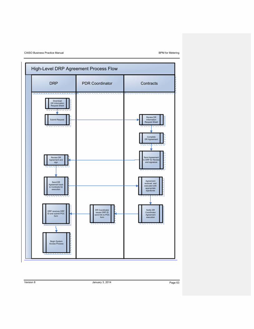
CAISO Business Practice Manual BPM for Metering
Version 8 January 3, 2014 Page 63
High-Level DRP Agreement Process Flow
DRP PDR Coordinator Contracts
DR Coordinator issues DRP ID
send link to POC form
Send Agreement to DRP for Review
and signature
Notify DR Coordinator Agreement execution
Agreement received and executed with appropriate signatures
Review DR Agreement and
sign
DownloadDR Information Request Sheet
Submit RequestReview DR Information
Request Sheet
Send DR Agreement back to Contracts for
execution
Complete DR Agreement
Begin System Access Process
DRP receives DRP ID and submit POC
form

CAISO Business Practice Manual BPM for Metering
Version 8 January 3, 2014 Page 64
12.3.2 Use of a Certified Scheduling Coordinator
The CAISO requires the use of a certified Scheduling Coordinator to be eligible to transact
business directly with the CAISO. A DRP could endeavor to become a certified Scheduling
Coordinator or use an existing certified Scheduling Coordinator. It is important to note that the
certification process for a new Scheduling Coordinator could take up to 120 days. A list of
certified Scheduling Coordinators is maintained on the CAISO Website, under the reference tab
of the operations center page. The DRP must enter into the appropriate contractual relationship
with a certified Scheduling Coordinator and notify the CAISO of the Scheduling Coordinator it
will be using; this can be done by a letter submitted to the attention of the CAISO’s “External
Affairs” group. By using a certified Scheduling Coordinator, all requirements, as outlined in the
BPM for Scheduling Coordinator Certification and Termination, will be maintained by the
Scheduling Coordinator and the DRP would not have to satisfy these requirements (for
example: system requirements, credit requirements, demonstration of market proficiency,
emergency procedures, and establishing qualifications to submit Settlement Quality Meter Data)
independently.
12.4 Demand Response System
The Demand Response System (DRS) will manage the registration process, and Meter Data
submission, and will calculate a Demand Response Energy Measurement for those participating
in the PDR productPDR’s and RDRR’s. Access to the system will require prior authorization
and a digital certificate.
Please review the DRS user guide and additional training material located at www.caiso.com.
Due to the nature of the transactions performed by the DRP and Scheduling Coordinator in the
CAISO Markets, the CAISO must have the ability to perform authentication and authorization for
users. This requires a very specific process to obtain user access to CAISO systems.
Therefore, the DRP and the SC must have their external point of contact on record with the
CAISO. Through the external point of contact, the DRP and SC can request access to the
needed system by submitting the User Application Access Request Form which can be found
on the CAISO’s information security page under the reference tab of the operations center on
the CAISO Website. Access to the Demand Response System will be granted based on the
information provided in the User Application Access Request Form
Since both the LSE and UDC for the underlying Load customers of a PDR or RDRR need the
ability to review the appropriate Load customer information during their registration process, the
CAISO Business Practice Manual BPM for Metering
Version 8 January 3, 2014 Page 65
CAISO will need to maintain a list of the responsible individuals from the LSEs and UDCs that
will perform the review of registration details in the Demand Response System. To ensure
timely reviews, the CAISO will request that the LSEs and UDCs provide their contact
information for the individuals that will perform the reviews.
The CAISO requests that, prior to entering their registration location information into the
Demand Response System, Demand Response Providers contact the CAISO to ensure that the
LSE of record for their registration locations already has access to the Demand Response
System. If not, the DRP will need to provide the LSE contact information to the PDR
coordinator at [email protected] [Is this still the correct CAISO recipient or is it now
Regulatory Contracts or something else?].
12.5 Proxy Demand Resource Registration
PDR and RDRR Resource ID
The PDR and RDRR Resource ID is a CAISO-assigned Resource ID that represents a Proxy
Demand Resource or Reliability Demand Response Resource in the CAISO Markets. The PDR
Resource ID will be used to bid, schedule, receive an award, receive Automated Dispatches
System (ADS) instructions and be settled in the CAISO Markets. There are certain steps that
must be accomplished by the DRP, LSE, UDC, and CAISO before the CAISO can assign a
PDR or RDRR Resource ID. The following explains the different types of PDR Resource IDs
and describes the application, review, and assignment steps.
Registrations and versus PDR Resource ID’s Relationship
Both pre-defined and custom Resource IDs will have a 1:1 relationship with a current
registration.
The CAISO is planning to phase in the establishment of business rules which will provide
for the capability of a PDR or RDRR Resource ID to have a “1:many” relationship with
current registrations.
The following process flow illustrates the PDR and RDRR Resource resource Registration registration Process process, Flow including the LSE/UDC review process and its timelines
Formatted: Highlight
Formatted: Highlight
Formatted: Font: Not Italic, Highlight
Formatted: Highlight

CAISO Business Practice Manual BPM for Metering
Version 8 January 3, 2014 Page 66
managed by the Demand Response SystemDRS prior to registration approval and resource ID assignment by the CAISO PDR Coordinator [Is this still the correct CAISO contact?]:
CA
ISO
UD
CLS
ED
RP
12.5.1 Applying for a PDR or RDRR Resource ID using the Demand
Response System Registration Process
Resource IDs: pre-defined and custom resources
There are two types of Resource ID setups that can be used in the CAISO Markets for PDR and
RDRR,: those comprised of pre-defined resources and those comprised of custom resources.
The use of pre-defined resources allows for quicker assignment of the DRP’s demand response
to the PDR Resource ID. The use of custom resources requires modifications to the Full
Network Model and therefore could have a timeline of up to 12 weeks120 – 180 days for a DRP
Formatted: Highlight

CAISO Business Practice Manual BPM for Metering
Version 8 January 3, 2014 Page 67
to apply for and receive a custom PDR Resource ID for use. The Resource IDs will look similar
to this example:
Pre-defined: PGSA_1_PDRP01, where PGSA represents the location of the demand
response by Sub-LapLAP
Custom resource: PRMNTE_6_PDRC01
Pre-defined resources use pre-established Generation Distribution Factors (GDFs) to allocate
the PDR or RDRR performance (generation) to the associated APNodes of the Sub-LapLAP. A
custom PDR or RDRR will be designed using historic Demand data (provided by the DRP) for
the specific network buses to calculate a unique GDF. For both pre-defined and custom
PDRsresources, the GDFs will remain static.
PDR and RDRR Resource ID criteria
All PDR and RDRR Resource IDs will be associated to the end use Loads represented by the
DRP based on:
The physical location, and
The Load Serving Entity (LSE) of individual end use Loads.
Therefore, prior to applying for a PDR Resource ID(s), the DRP must know which Sub-Lap LAP
the end use Loads are in and which LSE (and the LSE’s SC) serves the end use Load. This
information should be available to the DRP based on the requirement that it must have
contractual relationships with the end-use customer, LSE, and UDC. When requesting a PDR
Resource ID, the DRP should group its end use Loads by both the LSE and Sub-LapLAP.
Formatted: Space After: 6 pt
Formatted: Space After: 6 pt
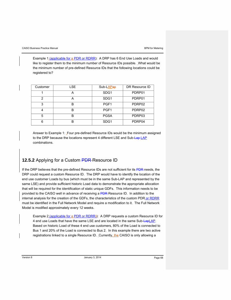
CAISO Business Practice Manual BPM for Metering
Version 8 January 3, 2014 Page 68
Example 1 (applicable for a PDR or RDRR): A DRP has 6 End Use Loads and would
like to register them to the minimum number of Resource IDs possible. What would be
the minimum number of pre-defined Resource IDs that the following locations could be
registered to?
Customer LSE Sub-LAPap DR Resource ID
1 A SDG1 PDRP01
2 A SDG1 PDRP01
3 B PGF1 PDRP02
4 B PGF1 PDRP02
5 B PGSA PDRP03
6 B SDG1 PDRP04
Answer to Example 1: Four pre-defined Resource IDs would be the minimum assigned
to the DRP because the locations represent 4 different LSE and Sub-Lap LAP
combinations.
12.5.2 Applying for a Custom PDR Resource ID
If the DRP believes that the pre-defined Resource IDs are not sufficient for its PDR needs, the
DRP could request a custom Resource ID. The DRP would have to identify the location of the
end use customer Loads by bus (which must be in the same Sub-LAP and represented by the
same LSE) and provide sufficient historic Load data to demonstrate the appropriate allocation
that will be required for the identification of static unique GDFs. This information needs to be
provided to the CAISO well in advance of receiving a PDR Resource ID. In addition to the
internal analysis for the creation of the GDFs, the characteristics of the custom PDR or RDRR
must be identified in the Full Network Model and require a modification to it. The Full Network
Model is modified approximately every 12 weeks.
Example 2 (applicable for a PDR or RDRR)): A DRP requests a custom Resource ID for
4 end use Loads that have the same LSE and are located in the same Sub-LapLAP.
Based on historic Load of these 4 end use customers, 80% of the Load is connected to
Bus 1 and 20% of the Load is connected to Bus 2. In this example there are two active
registrations linked to a single Resource ID. Currently, the CAISO is only allowing a

CAISO Business Practice Manual BPM for Metering
Version 8 January 3, 2014 Page 69
one-to-one relationship between registration and Resource ID. In the future that will
change to a “one-to-many” relationships. Here is how it will look:
Customer LSE Sub-LAPap
Location RegistrationGDF
Custom DR Resource ID
1 A PGF1 Bus 1 Reg 01 0.8 PRMNTE_6_PDRC01
2 A PGF1 Bus 1 Reg 01 PRMNTE_6_PDRC01
3 A PGF1 Bus 2 Reg 02 0.2 PRMNTE_6_PDRC01
4 A PGF1 Bus 2 Reg 02 PRMNTE_6_PDRC01
12.5.2.1 Requesting a Custom Resource ID with Dynamic GDF
If approved by the CAISO to do so, a DRP may submit GDFs as part of its Bid for a given PDR
or RDRR. In order to be eligible to submit GDFs as part of a Bid, the DRP must request and
receive approval from the CAISO to dynamically Bid GDFs. To request a custom GDF, please
contact the PDR coordinator at [email protected] [Is this still the correct CAISO contact?]with
the following information: Location of bus, and total MW. The custom GDF can be deployed
based on the Master File deployment cycle without the need to wait for the FNM deployment
cycle if only the GDF’s values, not the makeup of the PDR or RDRR, are changed from default
CAISO values.
12.5.3 Registration Levels
The CAISO will provide the ability to allow changes to the underlying end use Load customers
without having to issue a new Resource ID to the DRP. Registration levels were created to
allow flexibility for the DRP to revise its end use customers associated with a PDR or RDRR,
without having to request a new Resource ID. The registration level will also allow easier
application of the baseline, as will be explained below. The key aspect of the registration level
is that the meter data for both the baseline and the event day will need to be submitted to the
CAISO at the registration level of the Resource ID.
The Demand Response System will allow the DRP to create registrations. These registrations
must maintain the same standards as the overarching PDR or RDRR with underlying Load
represented by the same LSE and located in the same Sub-LAP. Each registration must
Formatted: Font: Not Italic
Formatted: Highlight
Formatted: Highlight
Formatted: Highlight

CAISO Business Practice Manual BPM for Metering
Version 8 January 3, 2014 Page 70
represent participation in the same market(s), and for a RDRR the registration must have the
same real-time dispatch option (marginal or discrete) and seasonal term designation. Additional
granularity is required for the physical locations of a registration. The location should contain
the end use customers that are on the same bus in the Sub-LapLAP. The Demand Response
System uses the term “location” to identify the end use customer data and bus location. In
addition, registrations will have defined start and end dates. This will allow for on-going
changes to occur at the registration level with limited impact to the effective date of the PDR or
RDRR in the Master File. Master File effective dates and PMax PmMax will only need to
change when the new registration’s reduction capacity is less than the current Master File
PMaxPmMax, or the DRP wants to change the current PMax PmMax to increase resource
capacity. Any Master File update may take 10 Business business Days days to implement.
Example 3 (applicable for a PDR only): A DRP has originally 4 customers all with the
same LSE and located in the same Sub-LAP and aggregated to one PDR Resource ID
(PDRP01). The PDR Resource ID became effective in the CAISO Markets markets on
April 1, 2010. The DRP receives the approvals for adding 2 additional customers to the
PDR Resource ID (same LSE and located in the same Sub-LapLAP) starting July 1,
2010. The DRP will create a second registration as shown below.
Customer LSE Sub-
LapLAP Registration
PDR Resource
ID
Registration Start date
Registration End date
1 A PGF1 Reg 01 PDRP01 04/01/10 06/30/10
2 A PGF1 Reg 01 PDRP01
3 A PGF1 Reg 01 PDRP01
4 A PGF1 Reg 01 PDRP01
1 A PGF1 Reg 02 PDRP01 07/01/10 12/31/10
2 A PGF1 Reg 02 PDRP01
3 A PGF1 Reg 02 PDRP01
4 A PGF1 Reg 02 PDRP01
5 A PGF1 Reg 02 PDRP01
6 A PGF1 Reg 02 PDRP01
Note: In this example you see that the PDR Resource ID stayed the same. The Meter
Data required for the baseline must represent the registrations and their timeline. So by

CAISO Business Practice Manual BPM for Metering
Version 8 January 3, 2014 Page 71
07/01/10 (or an event thereafter), the DRP will need to submit to the CAISO the
appropriate historic data for Registration 02 so that the baselines can be properly
calculated for future event dates after July 1.
For RDRR’s, the DRS will not allow a DRP to delete registrations during a rReliability dDemand
rResponse sServices tTerm (winter/summer) once the registration has been approved. The
approved registration and underlying end use load customers constitutingmposing the
registration must remain in effect and tied to the RDRR Resource ID until the end of the
Reliability Demand Response Services Term. Therefore, currently once a registration is created
for an RDRR Resource ID its registration and end use load customer composition will remain
the same until the end of the term. However, upon implementation of the “1:many” registration
functionality and business practice for PDR(s) and RDRR(s), additional locations may be added
to a RDRR Resource ID during a seasonal term by adding a new registration as represented in
the following example:
Example 4: (applicable for a RDRR upon implementation of one Resource ID to many
registrations capability): A DRP has originally 4 customers all with the same LSE and
located in the same Sub-LAP and aggregated to one Resource ID (PDRP02). The
Resource ID with original registration became effective in the CAISO markets on April 1,
2014 start of summer season and is participating for the summer Reliability Demand
Response Services Term only with a Discrete Real-Time Dispatch Option for that term.
The DRP receives the approvals for adding 2 additional customers to the Resource ID
(same LSE and located in the same Sub-LAP) starting July 1, 2014. The DRP will
create a second registration as shown below with additional customers.
Customer LSE SUB-LAP
Registration RDR
ResID
Term Discrete Start date End date
1 A PGF1 Reg 01 PDRP02 S Y 4/01/14 09/30/14
2 A PGF1 Reg 01 PDRP02 S Y
3 A PGF1 Reg 01 PDRP02 S Y
4 A PGF1 Reg 01 PDRP02 S Y
5 A PGF1 Reg 02 PDRP02 S Y 7/01/14 09/30/14
6 A PGF1 Reg 02 PDRP02 S Y
7 A PGF1 Reg 02 PDRP02 S Y
Formatted: Indent: Left: 0"
Formatted Table
Formatted Table
Formatted Table

CAISO Business Practice Manual BPM for Metering
Version 8 January 3, 2014 Page 72
12.5.4 Information Required When Applying for a PDR Resource ID
During the registration process for obtaining a PDR or RDRR Resource ID, the DRP must
provide specific information about the end use Loads involved in the Demand response. This
information is needed to allow the LSE, UDC, to review the location information and the CAISO
to approve the assignment of the PDR or RDRR Resource ID. This information will be:
Customer name (required field)
Service address (required field)
Service city (required field)
Sub-LAP location (required field)
Bus location (suggested for all but required field for Custom Resource only)
UDC service account number (required) Note: a location, identified by its UDC service
account number, cannot be registered to both a RDRR and a PDR for the same trading
day.
LSE (required field)
LSE’s Scheduling Coordinator (suggested for DRP to provide, required field for LSE to
verify or provide)
Profile information - Load load type, Load load reduction (required field)
Pseudo location information if applicable (per section 12.5.5)
For PDR, each registration must have a minimum of 100 KW of load reduction.
Additionally, for RDRR the following requirementsis applyicable:
Each registration must choose the Reliability Demand Response Services Term for
which it will remain active (summer, winter or both).
Each registration must have a minimum of 500 kW of load reduction.
Formatted: Font: Italic
Formatted: Indent: Left: 0"
Formatted: Bulleted + Level: 1 + Aligned at: 0.3" + Indent at: 0.55"
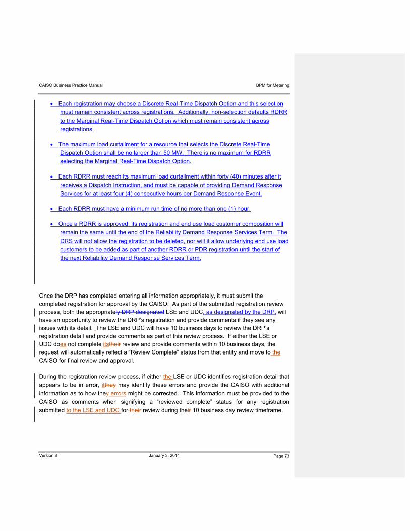
CAISO Business Practice Manual BPM for Metering
Version 8 January 3, 2014 Page 73
Each registration may choose a Discrete Real-Time Dispatch Option and this selection
must remain consistent across registrations. Additionally, non-selection defaults RDRR
to the Marginal Real-Time Dispatch Option which must remain consistent across
registrations.
The maximum load curtailment for a resource that selects the Discrete Real-Time
Dispatch Option shall be no larger than 50 MW. There is no maximum for RDRR
selecting the Marginal Real-Time Dispatch Option.
Each RDRR must reach its maximum load curtailment within forty (40) minutes after it
receives a Dispatch Instruction, and must be capable of providing Demand Response
Services for at least four (4) consecutive hours per Demand Response Event.
Each RDRR must have a minimum run time of no more than one (1) hour.
Once a RDRR is approved, its registration and end use load customer composition will
remain the same until the end of the Reliability Demand Response Services Term. The
DRS will not allow the registration to be deleted, nor will it allow underlying end use load
customers to be added as part of another RDRR or PDR registration until the start of
the next Reliability Demand Response Services Term.
Once the DRP has completed entering all information appropriately, it must submit the completed registration for approval by the CAISO. As part of the submitted registration review process, both the appropriately DRP designated LSE and UDC, as designated by the DRP, will have an opportunity to review the DRP’s registration and provide comments if they see any issues with its detail. The LSE and UDC will have 10 business days to review the DRP’s registration detail and provide comments as part of this review process. If either the LSE or UDC does not complete itstheir review and provide comments within 10 business days, the request will automatically reflect a “Review Complete” status from that entity and move to the CAISO for final review and approval. During the registration review process, if either the LSE or UDC identifies registration detail that
appears to be in error, itthey may identify these errors and provide the CAISO with additional
information as to how they errors might be corrected. This information must be provided to the
CAISO as comments when signifying a “reviewed complete” status for any registration
submitted to the LSE and UDC for their review during their 10 business day review timeframe.
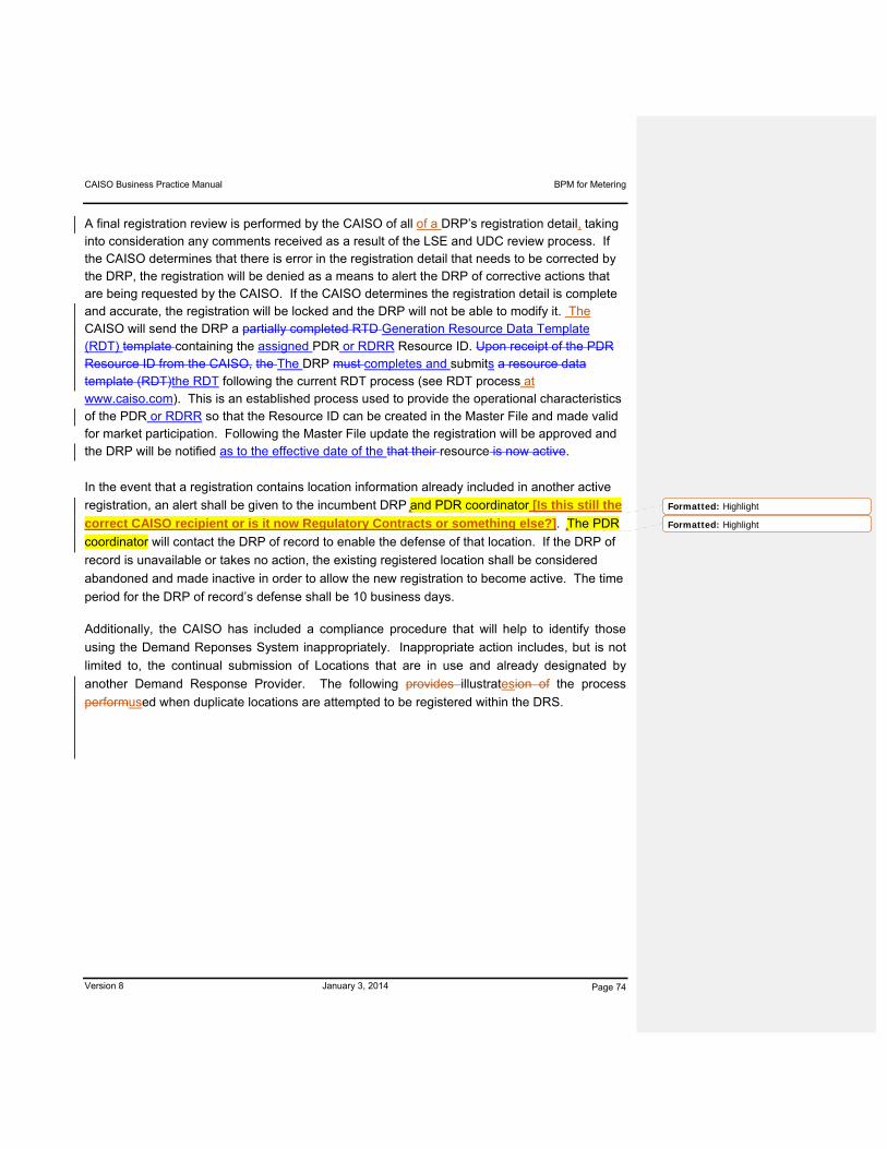
CAISO Business Practice Manual BPM for Metering
Version 8 January 3, 2014 Page 74
A final registration review is performed by the CAISO of all of a DRP’s registration detail, taking into consideration any comments received as a result of the LSE and UDC review process. If the CAISO determines that there is error in the registration detail that needs to be corrected by the DRP, the registration will be denied as a means to alert the DRP of corrective actions that are being requested by the CAISO. If the CAISO determines the registration detail is complete and accurate, the registration will be locked and the DRP will not be able to modify it. The CAISO will send the DRP a partially completed RTD Generation Resource Data Template (RDT) template containing the assigned PDR or RDRR Resource ID. Upon receipt of the PDR Resource ID from the CAISO, the The DRP must completes and submits a resource data template (RDT)the RDT following the current RDT process (see RDT process at www.caiso.com). This is an established process used to provide the operational characteristics of the PDR or RDRR so that the Resource ID can be created in the Master File and made valid for market participation. Following the Master File update the registration will be approved and the DRP will be notified as to the effective date of the that their resource is now active.
In the event that a registration contains location information already included in another active
registration, an alert shall be given to the incumbent DRP and PDR coordinator [Is this still the
correct CAISO recipient or is it now Regulatory Contracts or something else?]. The PDR
coordinator will contact the DRP of record to enable the defense of that location. If the DRP of
record is unavailable or takes no action, the existing registered location shall be considered
abandoned and made inactive in order to allow the new registration to become active. The time
period for the DRP of record’s defense shall be 10 business days.
Additionally, the CAISO has included a compliance procedure that will help to identify those
using the Demand Reponses System inappropriately. Inappropriate action includes, but is not
limited to, the continual submission of Locations that are in use and already designated by
another Demand Response Provider. The following provides illustratesion of the process
performused when duplicate locations are attempted to be registered within the DRS.
Formatted: Highlight
Formatted: Highlight
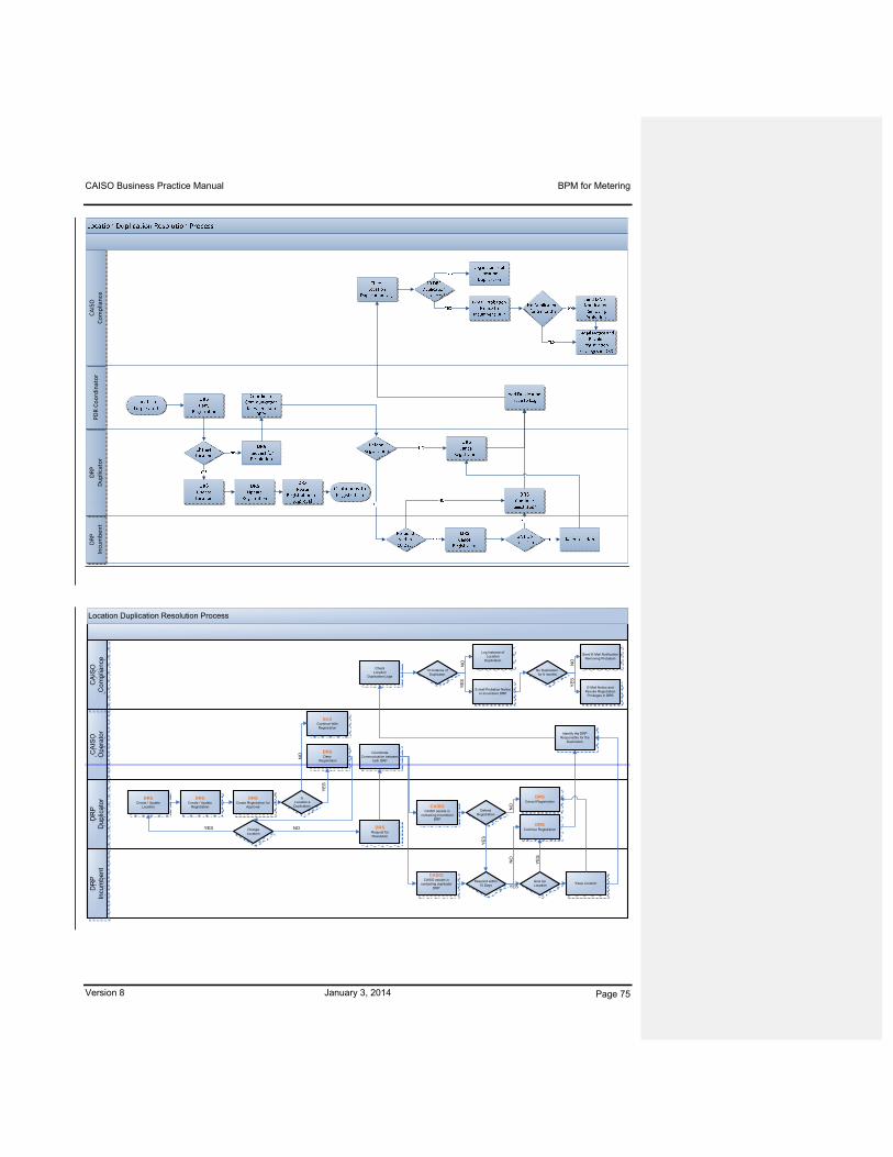
CAISO Business Practice Manual BPM for Metering
Version 8 January 3, 2014 Page 75
DRP
Incumbent
DRP
Duplicator
PDR Coordinator
CAISO
Compliance
Location Duplication Resolution Process
CA
ISO
O
pe
rato
rD
RP
Dup
licat
orD
RP
Incu
mbe
ntC
AIS
OC
om
plia
nce
DRSCreate / Update
Location
DRSCreate / Update
Registration
DRSCreate Registration for
Approval
Is Location a Duplication
End Continue With Registration
DRSDeny
Registration
Change Location
YES
YE
S
DRSRequest for Resolution
NO
Coordinate Communication between
both DRP
CASIOCAISO assists in
contacting Incumbent DRP
CASIOCAISO assists in
contacting duplicator DRP
Check Location
Duplication Logs
10 Instance of Duplicaton
Log instance of Location
Duplication
E-mail Probation Notice to Incumbent DRP
No Duplication for 6 months
Send E-Mail NotificationRemoving Probation
E-Mail Notice and Revoke Registration
Privileges in DRS
YE
SN
O
YE
SN
O
Respond within 10 Days
Defend Registration
DRSCancel Registration
DRSContinue Registration
Give Up Location
YE
S
NO
YES
NO
YE
S
Keep Location
NO
Identify the DRP Responsible for the
Duplication

CAISO Business Practice Manual BPM for Metering
Version 8 January 3, 2014 Page 76
12.5.5 Option for rRegistration of a Pseudo Location for PDR A pseudo location is designed to be used as a place holder to assist in managing a resource’s rated PMAXPmMax. The pseudo location resides only in the Demand Response System (DRS) and is established during the registration process of a PDR or RDRR[?]. The pseudo location may be used as a location capacity buffer in order to establish a PMAX PmMax greater than the initial registration of load reduction capacity for a resource. The PMAX PmMax registered including the pseudo location buffer, can then be the PMAX PmMax that is assigned to that resource ID in the master Master fileFile. This registration implementation detail is used to sync a resource’s predefined PMAX PmMax in the CAISO master fileMaster File to its load reduction capacity in the DRS allowing the master fileMaster File PMAX PmMax to stay constant.
Therefore, a pseudo location provides flexibility in the updating of registrations with the DRS and is designed to reduce the need to process those updates within the CAISO Master File reducing the amount of time necessary to obtain registration change approval.
This is accomplished by:
1. The DRP creates a pseudo location with a maximum load reduction capacity no greater than 2 MW.
2. The DRP submits a registration with all active locations and includes a pseudo location. 3. The CAISO sends the DRP a partially completed RDT if it is a new resource as part of
the registration process. 4. The DRP Ssubmits a RDT to establish the new PDR or RDRR[?] in the CAISO master
fileMaster File. 5. If the DRP is adding a pseudo location to an existing PDR or RDRR[?] a mMaster fFile
update request is submitted to adjust itstheir PMAX PmMax to the new value, including the pseudo location not to exceed an additional 2 MW.
6. The CAISO will validates the mMaster fFile PMAX PmMax in DRS against the requested Master File PMAX PmMax, taking into account the pseudo location capacity and ensure they are in sync as part of a mMaster fFile update approval process.
7. Each time a DRP adds location capacity to a previously approved resource, the load reduction capacity of the pseudo location should be adjusted so the total load reduction of the resource remains the same and is no greater than what has been assigned as the mMaster fFile PMAX PmMax for that resource.
Example:
DRP currently has 5 MWs of load reduction capability assigned to resource PGST_2_PDRP01. They DRP wants to create a 2 MWs buffer so itthey can manage itstheir portfolio more efficiently.
1. The DRP creates a pseudo location for resource PGST_2_PDRP01 with a load reduction capacity of 2 MWs.
Formatted: Highlight
Formatted: Font: Bold
Formatted: Font: Bold, Highlight
Formatted: Highlight
Formatted: Font: Bold, Highlight
Formatted: Highlight
Formatted: Font: Bold, Highlight

CAISO Business Practice Manual BPM for Metering
Version 8 January 3, 2014 Page 77
2. The DRP submits a registration with all of itstheir current active location totaling 5 MWs and a new pseudo location set to 2 MWs, with a total load reduction capacity for the registration set to 7 MWs in the DRS.
3. The DRP submits a master fileMaster File update to change PMAX PmMax for PGST_2_PDRP01 from 5 MWs to 7 MWs.
4. The Master fFile is updated upon CAISO approval.
A month later the DRP has an additional 1 MW of actual load reduction capability that itthey would like to add to resource PGST_2_PDRP01 registration.
1. The DRP updates the DRS to include an additional customer location with actual load capacity of 1 MW to the PGST_2_PDRP01 resource registration. This location is added to that resource’s registration in the DRS.
2. As part of the registration update for PGST_2_PDRP01, the pseudo location load reduction capacity is reset to 1 MW to reflect the additional customer location capacity and maintain the total load reduction capacity and PMAX PmMax of 7 MWs for that resource (i.e., actual location capacity + pseudo location capacity = registered resource PMAXPmMax).
3. The CAISO receives the registration, and confirms that the mMaster fFile PMAX PmMax is still the same as the DRS PMAX PmMax, and approves the registration.
4. The DRP’s SC submits meter data to reflect the changes to the new registration.
Creating a Pseudo Location in the DRS:
When registering a pseudo location, a DRP should:
Create a location name that begins with the prefix “PSEUDO LOC”., tThe DRP may add anything after “PSEUDO LOC”. This will identify the location as a pseudo location.
Create a unique UDC account number and assign it to the pseudo location to distinguishidentify it from all other locations and to ensure that the same UDC account number willould not be used to identify any other registered location in order to avoid location duplication. It is suggested that the UDC account number for any pseudo location begin with the ID of the DRP registering that location followed by a unique combination of letters and numbers not to exceed a maximum of 20 characters. Example: DPGE001psuedo
Ensure that there is only one pseudo location registered per resource.
Formatted: Font: Italic

CAISO Business Practice Manual BPM for Metering
Version 8 January 3, 2014 Page 78
Process Flow
The following process flow detail how a DRP would create a pseudo location and submit it to the CAISO as part of a registration and initial PDR setup. Formatted: Highlight
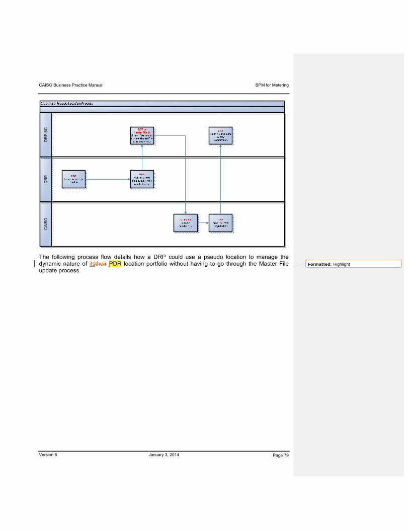
CAISO Business Practice Manual BPM for Metering
Version 8 January 3, 2014 Page 79
CA
ISO
DR
PD
RP
SC
The following process flow details how a DRP could use a pseudo location to manage the dynamic nature of itstheir PDR location portfolio without having to go through the Master File update process.
Formatted: Highlight
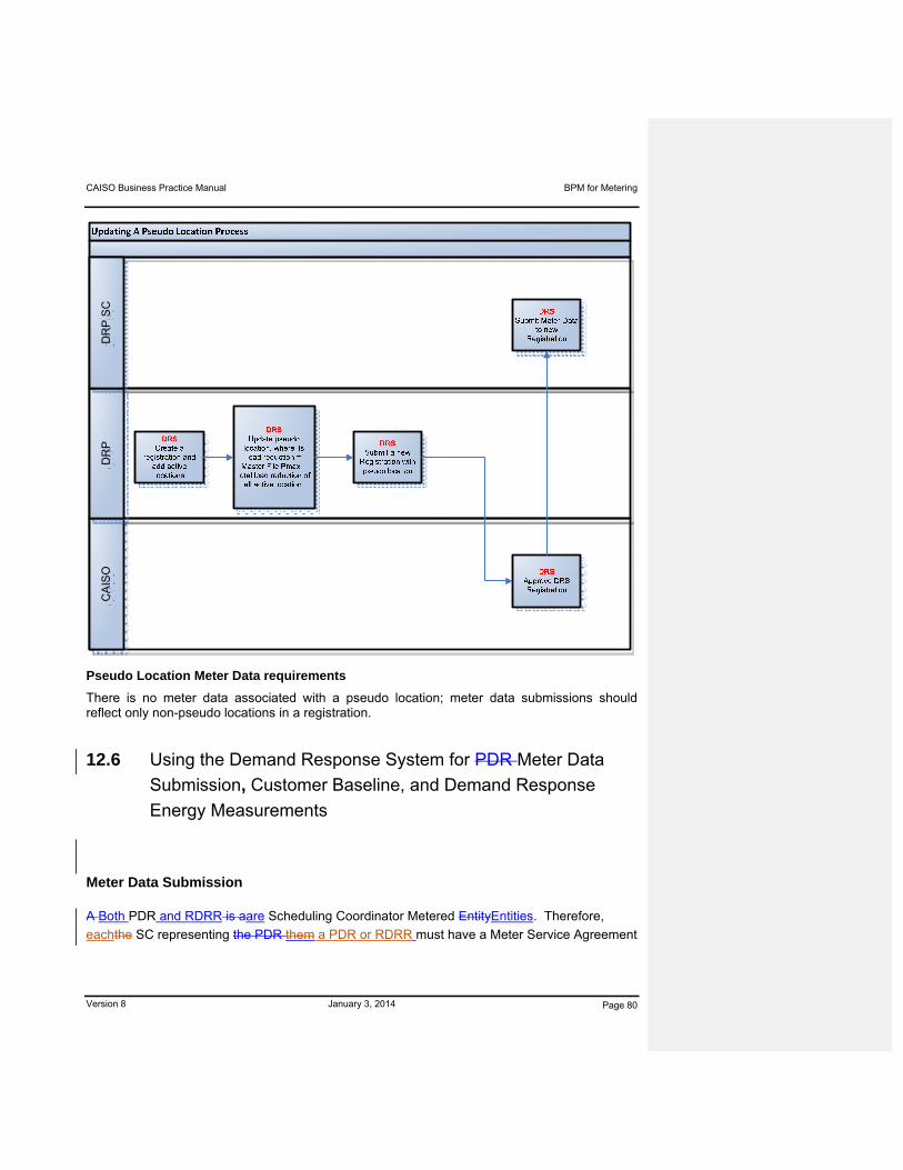
CAISO Business Practice Manual BPM for Metering
Version 8 January 3, 2014 Page 80
CA
ISO
DR
PD
RP
SC
Pseudo Location Meter Data requirements
There is no meter data associated with a pseudo location; meter data submissions should reflect only non-pseudo locations in a registration.
12.6 Using the Demand Response System for PDR Meter Data
Submission, Customer Baseline, and Demand Response
Energy Measurements
Meter Data Submission
A Both PDR and RDRR is aare Scheduling Coordinator Metered EntityEntities. Therefore,
eachthe SC representing the PDR them a PDR or RDRR must have a Meter Service Agreement

CAISO Business Practice Manual BPM for Metering
Version 8 January 3, 2014 Page 81
for Scheduling Coordinators (MSA SC) in place that supportsing its ability to submit Settlement
Quality Meter Data (SQMD) to the CAISO. During the time of registration of the PDR or RDRR,
access to the Demand Response System (DRS) will be granted based on the information
provided in the User Application Access Request Form.
Access will include set up for the SC to have the ability to submit SQMD (for calculation of
Recalculation settlement Settlement statements only per CAISO Tariff Section 10.3.6) into the
DRS for the registered PDR(s) or RDRR(s) it represents. Upon successful completion of the
registration process and prior to settlement of active participation in the CAISO Markets, (i.e.
awarded bids or schedules for provision of Ancillary Services, Energy or have been dispatched
in Real Time), forty-five (45) calendar days of historical Meter Data will need to be submitted for
establishment of the PDR’s or RDRR baseline. Prior to submittal, the DRP’s SC shall
aggregate the Settlement Quality Meter Data of the underlying PDRR or RDRR to the level of
the registration configuration in the DRS.
Meter Data submission will follow the “DRS Technical Interface Specifications” process located
under the metering section of the CAISO Website website and follow the timelines set forth in
CAISO Tariff Section 10 and the CAISO published settlement calendar.
Upon receipt of a PDR or RDRR Resource ID and its approval by the CAISO in the DRS, forty-
five (45) calendar days of historical Meter Data can be submitted at one time into the DRS as
part of the registration process or may be submitted at a later time. Baseline and Event Day
Meter Data is required for the PDR or RDRR in order to calculate a Demand Response Energy
Measurement for an event. If either Event Day or historical baseline Meter Data is absent, the
PDR or RDRR will have no Demand Response Energy Measurement calculated for Settlement.
SQMD must be submitted to the DRS for the PDR or RDRR as Load load to the effective
registration assigned in the DRS. Submittal of SQMD is required for all underlying Load load at
the registration level for the PDR or RDRR Resource ID. The key aspect of the registration
level is that the SQMD for both the baseline and the event day will need to be submitted to the
CAISO at the effective registration level for the PDR or RDRR Resource ID.
SQMD must be submitted for those trade dates which the PDR resource has received an award
for Non-Spinning Reserve, Energy or has been dispatched in Real Time. Meter Data
Submittal submittal timelines must be followed pursuant to section 10.3.6 of the CAISO Tariff.
Submittal of SQMD on a daily basis is the suggested best practice during those seasons in
which the PDR or RDRR is actively bidding into the CAISO markets, to ensure that both Event
Day and historical baseline Meter Data is available in the DRS for trade dates that bids are
awarded, is suggested as a best practice for PDRs, however, is not a requirement.

CAISO Business Practice Manual BPM for Metering
Version 8 January 3, 2014 Page 82
The CAISO shall calculate, account for and settle all charges and payments for Initial
Settlement Statement T+3B using CAISO estimates for all load and generation including
PDR(s) or RDRR(s). Therefore, no meter data can be submitted for the Initial Settlement
Statement T+3B calculation and Demand Response Energy Measurement for the PDR or
RDRR will be based on their Expected Energy and dispatch of that resource as calculated in the
Real-Time Market and as modified by any applicable corrections to the Dispatch Operating
Point for the resource pursuant to CAISO Tariff Section 11.1.4.
If there is no SQMD submitted into the DRS by the T+8B Meter Data submittal deadline, the
CAISO will continue to use the PDR or RDRR CAISO meter data estimations for the
Recalculation Settlement Statement T+12B calculation.
If there is no SQMD submitted into the DRS by T+48B Meter Data submittal deadline for the
recalculation Recalculation settlement Settlement statementStatement, the CAISO will not
estimate Meter Data for the underlying Load of the PDR or RDRR; the CAISO will be unable to
create a baseline, nor will it calculate a Demand Response Energy Measurement without
available SC-submitted SQMD, even if it was an event day. In addition, CAISO estimated Meter
Data will no longer be used in the subsequent recalculation Recalculation settlement Settlement
statementStatement.
Format for Meter Data submissions
Settlement Quality Meter Data submittal requires the following
Meter Data submittal for PDR or RDRR registrations selecting the CAISO 10 in 10 non-
event day selection baseline methodology must be as Load.
Meter Data submittal for PDR or RDRR registrations selecting a CAISO-approved
statistically derived baseline methodology must be as Generation.
Hourly intervals for twenty-four hours for Day-Ahead-only PDR or RDRR.
Five (5) minutes intervals for twenty-four hours if the resource is participating in Ancillary
Services (AS) or Real-Time Markets.
Meter Data submittals must include all twenty-four hours for any given trade date.
Partial data, incomplete data, or gaps in data will result in the inability of the DRS to
calculate a baseline and/or Demand Response Energy Measurement.
Five minute Meter Data can be created by parsing 15-minute recorded Meter Data into
three equal 5-minute intervals.

CAISO Business Practice Manual BPM for Metering
Version 8 January 3, 2014 Page 83
All data must be submitted in XML Format
The XML format details are listed on “Technical Interface Specification for DRS Exchange
Services” located on www.caiso.com.
Listed below is a table of the XML file schema for submitting the load and generation
information to the DRS with additional file submission requirements.
12.6.1 Customer Baseline
A Customer Baseline will be calculated by the DRS as a value or values based on historical
Load meter data in order to measure the delivery of Demand Response Services. The
Customer Baseline establishes a method for setting a customer’s baseline load, an estimate of
how much electricity a customer would have used had it not reduced its use in response to Day-
Ahead and Real-Time prices. The Customer Baseline of a PDR is compared against its actual
Load for a Demand response event in order to calculate the PDR Energy Measurement.

CAISO Business Practice Manual BPM for Metering
Version 8 January 3, 2014 Page 84
The following section specifies the methodology employed to calculate the Customer Baseline
for determination of a PDR’s PDR or RDRR performance.
12.6.1.1 Customer Baseline Methodology
10 in 10 non-event day selection method (an average of the load in the last 10 eligible
days)
12.6.1.2 Customer Baseline Window
The Customer Baseline window for Meter Data will be 45 calendar days from which the
10 most recent eligible days will be selected.
The selection of Customer Baseline data will include a number of the most recent days,
excluding different day-types and previous events days (definitions below)
Two different day-types will be supported:
o Weekday (Monday through Friday)
o Weekend/Holiday (Saturday, Sunday, or any NERC holiday)
A previous event day is a day on which there was either a PDR event, a RDRR event, or an
Outage recorded in SLIC. Previous event days are specific to the PDR or RDRR. The
following table specifies under which conditions a PDR or RDRR is considered to have an
“event day”.
Market Participation statusStatus event Event dayDay
Day-Ahead Schedule Yesyes yes
Real Time Energy Dispatch Yesyes yes
AS Capacity Award only (PDR only) Yesyes no
AS Energy Dispatch (PDR only) Yesyes yes
RUC Capacity Award only Yesyes no
Outage Yesyes yes
Non-CAISO Reliability Dispatch (RDRR only) Yesyes yes

CAISO Business Practice Manual BPM for Metering
Version 8 January 3, 2014 Page 85
The selection of Customer Baseline days is performed by iterating backward through the
acceptable days prior to the event day.
Once the target number of days is reached, selection ends.
If the target number of days is not reached, but the minimum number of days is reached,
the Customer Baseline is calculated on the selected days (see below).
If the minimum number of days is not reached, the highest usage prior event days within
the Customer Baseline window will be used to reach the minimum number of days. The
highest usage event days are defined as the highest totalized load for the resource
during event hours.
Target & minimums are defined as:
Weekday Weekend/Holiday
Target 10 4
Minimum 5 4
There is no elimination for “abnormally low” or “abnormally high” usage days.
The Customer Baseline shall be calculated as a simple hourly average of the selected
days’ Meter Data. (Note: five-minute Meter Data received for the selected days will be
converted to hourly data for the purposes of calculating the Customer Baseline, as
calculation is based on the average MWh consumption for each hour of the event period
across all the selected days).
The Customer Baseline will be calculated at the registration level to facilitate versioning
of the underlying customers in a registration.
12.6.1.3 Load Point Adjustment
The Customer Baseline calculation will include a symmetric multiplicative adjustment,
morning adjustment, unless otherwise requested by the DRP and approved by the
CAISO.

CAISO Business Practice Manual BPM for Metering
Version 8 January 3, 2014 Page 86
The multiplier will be calculated by averaging at the 4 hours prior to the event, excluding
the hour immediately prior to the event start and defined as the ratio of the average load
for these 3 hours relative to the same 3 hour average of the Customer Baseline
calculation data set. The same multiplier will be applied to each hour of the event.
The multiplier will be capped at both a 20% increase (load ratio = 1.2) and a 20%
decrease (load ratio = 0.8).
The following provide various Load Point Adjustment examples:
Example 7: Event Day/Hour: August 15, 2010 – HE 16
Load PDR
Meter
Raw
BaselineHE12 11 14
HE13 10.2 14.2
HE14 12.5 15.5
Average 11.23 14.57
Load Point Adjustment Ratio = PDR or RDRR Meter/Raw Baseline= 11.23 / 14.57
= .7707 or 77.07%
= 80%
Load Point Adjustment uses a floor of 80% as multiplier against raw Customer Baseline
to establish adjusted Customer Baseline
Example 8: Event Day/Hour: November 15, 2011 – HE 16
Load Meter Raw
Baseline HE12 18 15
HE13 19.2 15.2
HE14 20.75 16.5
Formatted Table
Formatted Table

CAISO Business Practice Manual BPM for Metering
Version 8 January 3, 2014 Page 87
Average 19.32 15.57
Load Point Adjustment = Meter/Raw Baseline
= 19.32 / 15.57
= 1.24 or 124%
= 120% Load Point Adjustment uses a ceiling of
120% as multiplier against raw Customer Baseline to establish adjusted Customer Baseline
Example 9: Event Day/Hour: August 15, 2011 – HE 12, 13, and HE18
Load Meter Raw
Baseline HE08 16 15
HE09 16.5 15.2
HE10 17. 5 16.5
Average 16.67 15.57
Load Point Adjustment = Meter/Raw Baseline
= 16.67 / 15.57
= 1.07 or 107%
A Load Point Adjustment of 107% will be applied as multiplier against raw Customer
Baseline to establish adjusted Customer Baseline for HE12 and 13.
Formatted Table

CAISO Business Practice Manual BPM for Metering
Version 8 January 3, 2014 Page 88
Load Meter Raw
Baseline HE14 16 17.13
HE15 16.5 17.25
HE16 17. 5 17.67
Average 16.67 17.35
Load Point Adjustment = Meter/Raw Baseline
= 16.67 / 17.35
= .96 or 96%
A Load Point Adjustment of 96% will be applied as multiplier against raw Customer Baseline
to establish adjusted Customer Baseline for HE18.
12.6.2 Customer Baseline and Demand Response Energy Measurements
– Demand Response System Calculations
The following details the calculation of raw and adjusted baselines and the Energy
measurements used in the settlement of PDR or RDRR:
Baseline Variables
r = registration
e = event day
d = historical basis day (days used for the
baseline)
h = hour (hours of the defined event)
m = 5 minute interval (0,5,10…55)
Formatted Table

CAISO Business Practice Manual BPM for Metering
Version 8 January 3, 2014 Page 89
x = discrete AS dispatch event for a PDR
n = number of 5 minute intervals in the specific
AS dispatch event
Adjustment Variables
s = adjustment window size (always 3)
t = adjustment window offset (always 2)
i = adjustment window start hour (for the
defined method, this is always min(h) – 4 )
j = adjustment window end hour (for the
defined method, this is always min(h) – 2 )
12.6.2.1 Baseline
A raw baseline for the registration (r) for a given PDR or RDRR for the event day for each event
hour using the historical basis days identified through the iterative process is calculated first:
Raw Baselinereh= (1 / (count (d)) * ∑d Loadrdh
Where Load is the SQMD submitted for underlying Load at the registration level for the PDR or
RDRR Resource ID.
Next, the adjustment ratio is calculated which will be used for this registration for the entire
event day based on the first event hour of the day. Note that h (the event hours) are those for
the entire PDR or RDRR, and are thus the same for all underlying registrations that are effective
on the event day.
i = min(h) – s - t + 1
j = min(h) - t
If ( i<1 )
o then Adjustmentre = 1
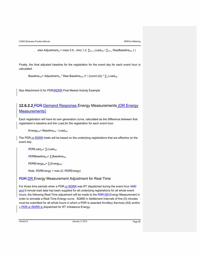
CAISO Business Practice Manual BPM for Metering
Version 8 January 3, 2014 Page 90
o else Adjustmentre = max( 0.8 , min( 1.2, ∑h=i..j Loadrdh / ∑h=i..j RawBaselinerdh ) )
Finally, the final adjusted baseline for the registration for the event day for each event hour is
calculated.
Baselinereh= Adjustmentre * Raw Baselinereh (1 / (count (d)) * ∑d Loadrdh
See Attachment G for PDR/RDRR Post Market Activity Example
12.6.2.2 PDR Demand Response Energy Measurements (DR Energy
Measurements)
Each registration will have its own generation curve, calculated as the difference between that
registration’s baseline and the Load for the registration for each event hour.
Energyreh= Baselinereh - Loadreh
The PDR or RDRR totals will be based on the underlying registrations that are effective on the
event day.
PDRLoadeh= ∑rLoadreh
PDRBaselineeh= ∑rBaselinereh
PDREnergyeh= ∑rEnergyreh
Note, PDREnergy = max (0, PDREnergy)
PDR DR Energy Measurement Adjustment for Real Time
For those time periods when a PDR or RDRR was RT dispatched during the event hour AND
and 5-minute load data has been supplied for all underlying registrations for all whole event
hours, the following Real-Time adjustment will be made to the PDR DR Energy Measurement in
order to simulate a Real-Time Energy curve. SQMD in Settlement Intervals of five (5) minutes
must be submitted for all whole hours in which a PDR is awarded Ancillary Services (AS) and/or
a PDR or RDRR is dispatched for RT Imbalance Energy.
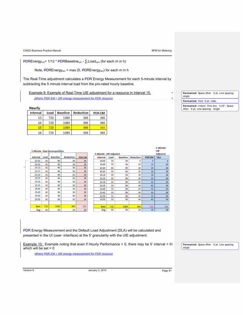
CAISO Business Practice Manual BPM for Metering
Version 8 January 3, 2014 Page 91
PDREnergyem= 1/12 * PDRBaselinereh - ∑rLoadrem (for each m in h)
Note, PDREnergyem = max (0, PDREnergyem) for each m in h
The Real-Time adjustment calculates a PDR Energy Measurement for each 5-minute interval by
subtracting the 5 minute interval load from the pro-rated hourly baseline.
Example 9: Example of Real-Time UIE adjustment for a resource in Interval 15.
Where PDR EM = DR energy measurement for PDR resource
PDR Energy Measurement and the Default Load Adjustment (DLA) will be calculated and
presented in the UI (user -interface) at the 5' granularity with the UIE adjustment.
Example 10: Example noting that even if Hourly Performance > 0, there may be 5’ interval < 0 which will be set = 0
Where PDR EM = DR energy measurement for PDR resource
Formatted: Space After: 6 pt, Line spacing: single
Formatted: Font: 9 pt, Italic
Formatted: Indent: First line: 0.25", SpaceAfter: 6 pt, Line spacing: single
Formatted: Space After: 6 pt, Line spacing: single

CAISO Business Practice Manual BPM for Metering
Version 8 January 3, 2014 Page 92
As noted, in this example hourly performance is positive but small, and thus 5' performance is
varied. All 5' performance intervals with negative energy measurement will be set = 0 as part of
the UIE adjustment calculation logic. Both PDR Energy Measurement and the Default Load
Adjustment (DLA) will be calculated and presented in the UI (user -interface) at the 5' granularity
with this UIE adjustment logic.
12.6.2.3 Default Load Adjustment (DLA)
When applicable, aA Default Load Adjustment will be used to adjust the UIE Settlement of the
LSE for the measured Energy of all PDR(s) or RDRR(s) associated with the LSE’s SC within a

CAISO Business Practice Manual BPM for Metering
Version 8 January 3, 2014 Page 93
particular DLAP. The Default Load Adjustment will also be based on the underlying
registrations that are effective on the event day within a given DLAP Load Resource ID.
DLADLAPresourceid = ∑PDREnergyDLAPresourceid
The PDR Energy Measurement will be provided as a Generation quantity and the Default Load
Adjustment data will be provided as a load quantity.
PDREnergyem = 1/12 * PDREnergyreh (for each m in h)
DLALoadem = 1/12 * DLAEnergyreh (for each m in h)
If a DRP’s SC fails to submit SQMD for a PDR or RDRR, then the CAISO will be unable to
create a baseline or calculate the PDR Energy Measurement for the resource even if it was an
event day for that resource. Therefore, there would be no default load adjustment associated
with the PDRresource and there will be no adjustment made to the Meter Data of the resources
LSE’s SC Default LAPap resource ID of the LSE for that particular PDR or RDRR which would
have an impact to the UIE Settlement of the LSE in which the PDR or RDRR resided.
Additionally, the CAISO is indifferent to the treatment of Estimated Settlement Quality Meter
Data and Actual Settlement Quality Meter Data submitted by the LSE’s SC for the DLAP
Resource ID in which a PDR or RDRR may be associated. The CAISO will create a Default
Load Adjustment and apply it to either the ESQMD or SQMD submitted. The Default Load
Adjustment will also be applied to CAISO Estimated Settlement Quality Meter Data if applicable,
in the event that no meter data is submitted by the LSE’s SC for the DLAP Resource ID by
T+8B (see CAISO Tariff Section 10.3.6.2). The Default Load Adjustment will not be calculated,
estimated, nor will it be applied for the Initial Settlement Statement Calculation or for any
Recalculation Settlement Statement Calculation for those PDRs or RDRR for which CAISO
Estimated Meter Data is calculated.
12.7 PDR No Pay Dispatch Performance (meter before/after in 5
minute intervals)
A PDR that is dispatched for Energy from Ancillary Service capacity must show a reduction in
the underlying load equal to the amount of the Dispatch within 10 minutes, as well as sustain
the response for the duration of the Dispatch. In contrast, the baseline methodology for
Instructed Imbalance Energy Settlement measures response relative to typical usage.
Therefore, the CAISO will use a “meter before/ meter after” approach for the Undelivered
category of No Pay for Spinning and Non-Spinning Reserve, even though the settlement of
Instructed Imbalance Energy will use the PDR Energy Measurement method. The meter

CAISO Business Practice Manual BPM for Metering
Version 8 January 3, 2014 Page 94
before/after amount calculated by the Demand Response System is called PDR No Pay
Dispatch Performance.
Note: SQMD in Settlement Intervals of five (5) minutes must be submitted for all 24 hours for a
trade date in which a PDR is awarded Ancillary Services (AS) or has been dispatched for AS
and/or RT Imbalance Energy.
First, PDR Load total for the unique PDR AS dispatch event x is calculated. Unique PDR AS
dispatch events are defined as each contiguous time period where the PDR Non-Spin IIE > 0.
Note that m=0 represents the interval immediately prior to the event, with 1 to n as the
subsequent 5 minute intervals. For an AS dispatch event that extends across operating hours,
an adjustment to the PDR No Pay Dispatch Performance is made based on the baseline
calculated in Section 12.6.2.1. This baseline adjustment ensures that the load curtailment
offered as an ancillary service is not a normal hourly load variation.
PDRLoadexm= ∑rDemandrem (for each registration for m=0..n that is within x)
Hourly Baseline Adjustmentreh=i = Baselinereh=0 - Baselinereh=i
Where h = 0 is the hour where the AS dispatch event begins and h = i is each
consecutive hour in which the AS dispatch event continues.
Finally, calculate the performance for each interval after the event start.
PDRNoPayDispatchPerformanceexm = max(0, -1/12*(Hourly Baseline Adjustmentreh=i) +
(PDRLoadexm=0 - PDRLoadexm)) (for each m=1..n)
Five-minute PDR No Pay Dispatch Performance values calculated by the Demand Response
System will be submitted to the settlement system as a Generation quantity. Five-minute PDR
No Pay Dispatch Performance values will be summed to the ten-minute Settlement Interval to
determine compliance with Dispatch Instructions. The No Pay methodology for Ancillary
Service compliance is described in the BPM for Settlements and Billing.
12.8 PDR or RDRR Hourly Generation – Alternative Baseline for
PDR Demand Response Energy Measurement
A Demand Response Provider representing a PDR or RDRR may submit a written
application to the CAISO for approval of a methodology for deriving Settlement Quality

CAISO Business Practice Manual BPM for Metering
Version 8 January 3, 2014 Page 95
Meter Data, referred to in this BPM as Generation Data, for the PDR or RDRR that consists
of a statistical sampling of Energy usage data (CAISO Tariff Section 10.1.7).
12.9 DRS Monitoring Process
The CAISO will monitor through the DRS and business processes the performance of the PDR or RDRR. In general, the CAISO will look at certain metrics across all PDR(s) andor RDRR(s) and will flag those which fall outside typical ranges. However, based on monitoring results, the CAISO will takeseek actions pursuant toas outlined in CAISO Tariff Section 30.6.3.
12.10 Outages
A PDR orand RDRR resources areis allowed to have outages, but will be limited to updates to
itsa resources ramp rates, or to modifying itsthe capacity to 0. PDR and RDRR resources are
an all-or-nothing resources, which limits how much sucha resources can be derated. TheyPDR
and RDRR are also prevented from submitting a rerated of their PMin. SLIC has been updated
to enforce these business rules.
SLIC has been updated to permit a PDR or RDRRresource to submit only PMax derates or
Ramp Rate derates. Any other data entered in SLIC through either the UI or API for a PDR or
RDRR Resource ID shall return an error message. It also has validation to restrict PMax
derates entries for PDR and RDRR Resource IDs to be only 0 MW. A PMax derate is used to
indicate a day should not be used in the baseline calculation. Since a day is either valid or
invalid, no partial derates are permitted. Any PMax value other than 0 MW entered in SLIC
through either the UI or API for a PDR or RDRR Resource ID shall return an error message.
When submitting outages, Scheduling Coordinators must only use one or both cause
codes designated for PDR(s) or RDRR(s) resources.10100 – anomalous days for
baseline calculations
10101- Unavailability of awarded AS capacity
In order to keep a Resource ID active and reduce the need to make updates to the CAISO
Master File, the DRP using itstheir scheduling coordinator can submit extended outages to
derate itstheir resource to 0 MW when itthey does not wish to participate in the market.
Formatted: Font: Bold

CAISO Business Practice Manual BPM for Metering
Version 8 January 3, 2014 Page 96
Attachment A
END USE METER STANDARDS

CAISO Business Practice Manual BPM for Metering
Version 8 January 3, 2014 Page A-1
Attachment A: End Use Meter Standards
All metering is of a revenue class metering accuracy in accordance with the ANSI C12
standards on metering and any other requirements of the relevant UDC or Local Regulatory
Authority that apply. Such requirements apply to meters, current transformers, potential
transformers, and associated equipment. ANSI C12 metering standards include the following:
ANSI C12.1 – American National Standard Code For Electricity Metering
ANSI C12.6 – American National Standard For Marking And Arrangement Of Terminals
For Phase-Shifting Devices Used In Metering
ANSI C12.7 – American National Standard For Watt-hour Meter Sockets
ANSI C12.8 – American National Standard For Test Blocks And Cabinets For installation
Of Self-Contained A-Base Watt-hour Meters
ANSI C12.9 – American National Standard For Test Switches For Transformer-Rated
Meters
ANSI C12.10 – American National Standard For Electromechanical Watt-hour Meters
ANSI C12.11 – American National Standard For Instrument Transformers For Revenue
Metering, 10 kV BIL Through 350 kV BIL
ANSI C12.16 – American National Standard For Solid-State Electricity Meters
ANSI C12.18 – American National Standard For Protocol Specification For ANSI Type 2
Optical Port
ANSI C12.20 – American National Standard For Electricity Meters 0.2 and 0.5 Accuracy
Class
ANSI C57.13 – IEEE Standard Requirements for Instrument Transformers

CAISO Business Practice Manual BPM for Metering
Version 8 January 3, 2014 Page B-1
Attachment B
TECHNICAL SPECIFICATIONS

CAISO Business Practice Manual BPM for Metering
Version 8 January 3, 2014 Page B-1
Attachment B: Technical Specifications
Section A. Meter Configuration Criteria
A1 Power Flow Conventions
Meters must be installed and configured in such a manner so as to define the 4 Quadrants
referred to in Exhibit B-1.
A2 CAISO Standard Meter Memory Channel Assignments
Metering Facilities must be installed and configured in such a manner so as to comply with the
following CAISO requirements:
Channel 1 must record active power (kWh) delivered by the CAISO Controlled Grid;
Channel 2 must record reactive power (kVARh) delivered by the CAISO Controlled Grid;
Channel 3 must record reactive power (kVARh) received by the CAISO Controlled Grid;
Channel 4 must record active power (kWh) received by the CAISO Controlled Grid
For metering with bi-directional power flows, CAISO reserves the right to require metering that
measure and report 4 quadrant VARs. Situations like a generating plant that nets gross
generator output and auxiliary loads on one meter, which could swap from a supplying to a
buying mode and vice versa may require this type of metering. To properly account for such
cases, six channels of data are required. This configuration is considered optional unless
specified by CAISO as required. Such Metering Facilities must be installed and configured in
such a manner so as to comply with the following CAISO requirements:
Channel 1 must record active power (kWh) delivered by the CAISO Controlled Grid;
Channel 2 must record quadrant 1 reactive power (kVARh) delivered by the CAISO
Controlled Grid;
Channel 3 must record quadrant 3 reactive power (kVARh) received by the CAISO
Controlled Grid;
Channel 4 must record active power (kWh) received by the CAISO Controlled Grid;
Channel 5 must record quadrant 2 reactive power (kVARh) delivered by the CAISO
Controlled Grid;

CAISO Business Practice Manual BPM for Metering
Version 8 January 3, 2014 Page B-2
Channel 6 must record quadrant 4 reactive power (kVARh) received by the CAISO
Controlled Grid.
A3 CAISO Standard Meter Display Modes
The following display readings must be displayed in the normal display mode to comply with
CAISO requirements.
Normal Display Mode (Standard Configuration, Uni-directional/Bi-directional kWh and
kVARh)
For standard metering applications the display items should be utilized in the sequence listed
below. When metering uni-directional power flows, the quantities listed below that do not apply
(i.e. for generation only applications, the delivered quantities should have zero accumulation)
may be omitted. The only exception to this is where the display items correlate to the load
profile channel assignments. The 4 display readings that correlate to the 4 load profile channels
must also be displayed.
Exhibit A-1 – Normal Display Mode (Standard Configuration)
1 Device ID
2 Date/Time MM:DD:YYHH:MM:SS (Standard Time6, military format)
3 Total kWh delivered by the CAISO Controlled Grid
4 Maximum kW (5 minute or hourly demand interval) delivered by the CAISO
Controlled Grid
5 Date and time of maximum kW delivered by the CAISO Controlled Grid
6 Total kVARh delivered by the CAISO Controlled Grid
7 Total kVARh received by the CAISO Controlled Grid
8 Total kWh received by the CAISO Controlled Grid
9 Maximum kW (5 minute or hourly demand interval) received by the CAISO
Controlled Grid
10 Date and time of maximum kW received by the CAISO Controlled Grid
Normal Display Mode (Optional Configuration, Bi-directional kWh and Four Quadrant
kVARh) 6 Meter may not shift to Day-Light Savings Time

CAISO Business Practice Manual BPM for Metering
Version 8 January 3, 2014 Page B-3
For metering bi-directional power flows in which CAISO requires optional 4 quadrant VAR
measurement, the following display items should be displayed in the sequence listed below:
Exhibit A-2 Normal Display Mode (Optional Configuration)
1 Device ID
2 Date/TimeMM:DD:YY:HH:MM:SS (Standard time, military format)
3 Total kWh delivered by the CAISO Controlled Grid
4 Maximum kW (5 minute or hourly demand interval) delivered by the
CAISO Controlled grid
5 Date and time of maximum kW delivered by the CAISO Controlled Grid
6 Total kVARh for Quadrant 1
7 Total kVARh for Quadrant 2
8 Total kVARh for Quadrant 3
9 Total kVARh for Quadrant 4
10 Total kWh received by the CAISO Controlled Grid
11 Maximum kW (5 minute or hourly demand interval) received by the CAISO
Controlled Grid
12 Date and time of maximum kW received by the CAISO Controlled Grid
Consumption Values
The consumption values must be in XXXXX.X format and demand in XXXX.XX format. The
register-scaling factor should be set such that the display does not roll over in less than 60 days.
A3.1 Alternate Display Mode
The values listed below should be displayed in the alternate display mode to comply with
CAISO requirements:
Instantaneous kW delivered and received by the CAISO Controlled Grid (for bi-
directional power flows and/or applications where the power flow is received by the
CAISO Controlled Grid)
Phase A, B and C voltage magnitude and phase angle
CAISO Business Practice Manual BPM for Metering
Version 8 January 3, 2014 Page B-4
Phase A,B and C current magnitude and phase angle
Neutral current magnitude and phase angle (if available)
When available, the alternative display mode may also be used by CAISO Metered Entities to
display other definable quantities in sequence after the values defined above.
A3.2 Test Mode Display
The following values should be displayed in the test mode to comply with CAISO requirements:
Total pulse count or energy measured for test; and
Total consumption during test.
During the test mode the above values should be provided for each function being tested
(Watts, VARs). The data displayed by the meter while in test mode must not change the normal
mode display registers and should not be recorded in the load profile channels. This
requirement is imposed to prevent the test data from being recorded as actual load/generation
data. CAISO Metered Entities can add additional display quantities in sequence in the values
defined above.
A4 Transformer and Line Loss Correction Factor
CAISO Metered Entities are responsible for properly calculating and applying the Transformer
and Line Loss Correction Factor to the meter to reflect point of delivery to the CAISO Controlled
Grid.
A5 Distribution Compensation Factor (DCF)
If applicable per BPM section 5.1.1, CAISO Metered Entities are responsible for obtaining an
agreed upon distribution compensation factor from the appropriate UDC/Distribution Company/
interconnection entity and applying it to the meter to reflect losses or credits attributed across a
Distribution System to the point of delivery to the CAISO Controlled Grid.
A6 CT/VT and Cable Loss Correction Factors
Where the connected burden of a metering circuit exceeds the burden rating of a CT or VT or if
an existing instrument transformer does not meet the minimum CAISO accuracy requirements,
then one of the actions listed below must be taken:

CAISO Business Practice Manual BPM for Metering
Version 8 January 3, 2014 Page B-5
a. Replace the instrument transformer(s) with higher burden rated revenue class units; or
b. Reduce the burden on the circuit to comply with the name plate of existing instrument
transformer(s); or
c. Apply correction factors to the meter to adjust the meter’s registration to compensate for
inaccuracies.
CAISO Metered Entity is responsible for properly calculating and applying the CT/VT and cable
loss correction factors to its meters in accordance with this BPM to adjust for inaccuracies in the
metering circuit.
A7 Special Applications, Configurations and Unique Situations
CAISO Metered Entities are responsible for providing CAISO with the necessary Meter Data
and other information to enable CAISO to prepare Settlement Quality Meter Data. For instance,
where there is a Generating Unit with multiple generators and auxiliary Loads, CAISO Metered
Entity provides appropriate information (i.e. documentation, descriptions, one-line diagrams,
etc.) to CAISO of each unit under all combinations of generation and load (e.g. where only one
generator is operating but all auxiliary Loads are beings supplied).

CAISO Business Practice Manual BPM for Metering
Version 8 January 3, 2014 Page B-6
Section B. Standards for Metering Facilities
This section provides additional details to the standards referred to in Attachment A of this BPM.
The standards referred to in Attachment A of this BPM and this section apply to CAISO Metered
Entities and, where the relevant Local Regulatory Authority has not set any standards, to
Scheduling Coordinator Metered Entities.
B1 Standards for Existing Metering Facilities
Existing metering facilities are those facilities that were fully installed as of the CAISO
Operations Date. Existing Metering Facilities used by CAISO Metered Entities shall meet the
following general standards:
Revenue quality instrument transformers at the generator output level (specifically at all
main generators, banks and local distribution load supplied from the generator) must
have an accuracy of 0.3% or better,
Generator auxiliary load metering must have an overall accuracy of 3% or better
Revenue quality instrument transformers at transmission metering points must have an
accuracy of plus or minus 0.3% or better.
Note: Any modifications to Existing Metering Facilities are required to meet the standards
outlined in Section B2.
B2 General Standards for CAISO Meters
New meters are those meters that are installed after the CAISO Operations Date. Meters must
meet the following general standards:
They must be revenue quality with a 0.2 Accuracy Class
They must be remotely accessible, reliable, 60 Hz, three phase, bi-directional,
programmable and multifunction electronic meters certified for correct operation at the
service voltage
They must be capable of measuring kWh and kVARh and providing calculated three
phase values for kVAh, kVA
They must have a demand function including cumulative, rolling, block interval demand
calculation and maximum demand peaks

CAISO Business Practice Manual BPM for Metering
Version 8 January 3, 2014 Page B-7
There must be battery backup for maintaining RAM and a real-time clock during outages
of up to thirty days
There must be AC potential indicators on each of the three phases
They must be capable of being powered either internally from the bus or externally from
an AC source. It is recommended that all CAISO meters have an auxiliary source or
emergency backup source of power.
They must be capable of providing RMDAPS (MV-90 addressable metering protocol)
They must be capable of 60 days storage of kWh, KVARh, and/or 4 quadrant interval
data
If there is any inconsistency between these general standards and the detailed standards
referred to in paragraphs B3 and B4 of this Part, the detailed standards prevail.
B3 Detailed Standards for New Meters
Exhibit B-1 to this Attachment provides the detailed specifications with which new meters must
comply.
B4 Detailed Standards for Coupling Capacitive Voltage Transformer (CCVT), Optical
Sensor and New Oil Filled, Wound Instrument Transformers
Exhibit B-2 to this Attachment provides the detailed specifications with which new oil filled,
wound instrument transformers must comply.

CAISO Business Practice Manual BPM for Metering
Version 8 January 3, 2014 Page B-8
Exhibit B-1 to Section B
CAISO ENGINEERING SPECIFICATION
FOR POLYPHASE SOLID-STATE
ELECTRICITY REVENUE QUALITY METERS
CAISO Business Practice Manual BPM for Metering
Version 8 January 3, 2014 Page B-9
Attachment B: Section B Exhibit B-1: Table of Contents
B1: 1 GENERAL INFORMATION B1: 2 SCOPE B1: 3 METERING FUNCTIONS B1: 4 DISPLAY REQUIREMENTS B1: 5 METER DIAGNOSTICS B1: 6 PROGRAMMING AND SOFTWARE B1: 7 COMMUNICATION B1: 8 OPTIONAL METER FUNCTIONS B1: 9 ACCURACY B1: 10 ELECTRICAL REQUIREMENTS B1: 11 MECHANICAL REQUIREMENTS B1: 12 SECURITY B1: 13 METER APPROVAL TESTING B1: 14 SAFETY B1: 15 DATA SECURITY AND PERFORMANCE B1: 16 DOCUMENTATION B1: 17 APPLICABLE STANDARDS B1: 18 DEFINITIONS

CAISO Business Practice Manual BPM for Metering
Version 8 January 3, 2014 Page B-10
B-1: 1 GENERAL INFORMATION
This Exhibit applies to all solid-state polyphase electricity meters used in revenue metering applications on the CAISO Controlled Grid (meters) and provides the minimum functional and performance requirements for meters. All requirements in this Exhibit are intended to ensure the expected life cycles, security, accuracy, reliability and minimum maintenance requirement of meters. Some requirements, however, are specified to maintain the compatibility and interchangeability of the meter.
B-1: 2 APPLICABILITY
Meters approved under this Exhibit may not be required to have all of the specified features. Meters must meet the specified minimum requirements and the requirements of Section B1: 13 (Meter Approval Testing) of this Exhibit.
B-1: 3 METERING FUNCTIONS
B-1: 3.1 Measured Quantities
As used in this Exhibit, the term “delivered” applies to Energy flowing out of the CAISO Controlled Grid and the term “received” applies to Energy flowing into the CAISO Controlled Grid.
B-1: 3.1.1 Consumption
The following consumption quantities are required for all meters approved for use on the CAISO Controlled Grid:
(a) Kilowatt-hours—delivered;
(b) Kilowatt-hours—received;
(c) Kilovar-hours—delivered, received, for each quadrant;
(d) Kilovoltamp-hours—delivered, received, for each quadrant;
(e) Ampere-squared-hours; and
(f) Volts-squared-hours.
B-1: 3.1.2 Demand
The following demand quantities are required for all meters approved for use on the CAISO Controlled Grid:
(a) Kilowatts—delivered;
(b) Kilowatts—received;
(c) Kilovars—delivered, received, for any quadrant; and

CAISO Business Practice Manual BPM for Metering
Version 8 January 3, 2014 Page B-11
(d) Kilovoltamps—delivered, received, for any quadrant.
B-1: 3.1.3 Power Factors
The CAISO may specify average power factors for the previous demand sub-interval in any quadrant or any combination of two quadrants.
B-1: 3.1.4 Reverse Consumption/Demand
The meter must be programmable to take one of the following actions for reverse consumption and demand quantities:
(a) Ignore the reverse quantities; and
(b) Add the reverse quantities to the appropriate consumption and demand quantities.
B-1: 3.2 Basic Default Metering Function
When power is applied to the meter, it must immediately begin recording bi-directional total kilowatt-hours. Received power flow must carry a negative sign. This function must be performed regardless of whether the meter is programmed or not and cannot require a battery. An unprogrammed meter must indicate that it is unprogrammed. CAISO may request a meter to be programmed with a specific program.
B-1: 3.3 Demand Metering Function
Meters must have the following demand metering functions:
(a) As a minimum, the meter must be programmable for fixed and/or rolling interval demand calculations on bi-directional kilowatts and kilovars;
(b) The meter is programmable for one minute delivered kilowatt demand (as an approximation of “instantaneous” kilowatts delivered) in addition to the rolling interval demand calculation. The one minute demand is not required to be synchronous with the other demand quantities;
(c) The meter is programmable for rolling interval demand calculations for any optional demand quantity (see Section B-1: 3.1.2) that CAISO specifies.
(d) Demand intervals are programmable for durations of 5, 10, 15, 30 or 60 minutes;
(e) Demand functions are capable of temporary suspension for a programmable time interval after power is restored following a power outage. The length of time is programmable from zero to 60 minutes in one-minute intervals;
(f) After a demand reset, further manual demand resets are prevented with a programmable lockout time. A demand reset from a meter programmer connected to the optical port is not subject to this delay and can be initiated as frequently as required; and

CAISO Business Practice Manual BPM for Metering
Version 8 January 3, 2014 Page B-12
(g) If the meter has been programmed for Time-of-Use (TOU) functions, the time at which maximum demand occurred is recorded at the end of that demand interval.
B-1: 3.4 Load Profile Function
Meters have the following load profile functions:
(a) CAISO may specify that the meter provide load profile recording of interval data for 1 to 4 channels of consumption quantities;
(b) Date and time is stored with the load recording of interval data;
(c) Load recording of interval data uses a “wraparound” memory that stores new interval data by writing over the oldest interval data;
(d) The load recording of interval data function is capable of storing and communicating a minimum of 60 days of 4 or 6 channel, 5 minute interval data, in addition to allowances for event recording (power outages, resets, time sets, etc.);
(e) The load recording of interval data function has the capacity to count and store at least 4,095 counts in a 5 minute period of time; and
(f) Load recording of interval data continues while the meter is communicating with a meter programmer connected to the optical port.
B-1: 3.5 Function during Power Disturbances
Meters have the following functions during power disturbances:
(a) During powerline disturbances such as brownout or outage conditions the meter maintains all meter data as well as time keeping functions. Display and communication functions are not required during these conditions;
(b) The meter can withstand the following outages during a continuous ten year or longer service without the need to maintain its auxiliary power system, including replacing the battery:
i. 20 short outages per year of less than 30 seconds per outage; and
ii. 30 days of continuous/cumulative outage;
(c) During a power outage, critical program and billing data is written to non-volatile memory. When power is restored, data is returned to active memory and data collection resumed;
(d) Following a power outage, register “catch-up” time is a maximum of 30 seconds. During the “catch-up” time the meter still calculates consumption and demand quantities. Optional inputs and outputs also function during this time;

CAISO Business Practice Manual BPM for Metering
Version 8 January 3, 2014 Page B-13
(e) During power outages, time is maintained with a cumulative error of no more than 2 minutes per week (0.02%);
(f) The meter records the date and time of any power outage; and
(g) Meters may also record the duration of any power outage.
B-1: 3.6 Meter Test Mode Function
Meters have the following meter test mode functions:
(a) The meter has the capability of a Test Mode function that suspends normal metering operation during testing so that additional consumption and demand from the tests are not added to the meter’s totals;
(b) The Test Mode function is activated by a permanently mounted physical device that requires removal of the meter cover to access or by a meter programmer connected to the optical port;
(c) Activation of the Test Mode causes all present critical billing data to be stored in non-volatile memory and restored at the time of exit from the Test Mode;
(d) Upon activation of the Test Mode, register displays accumulate beginning from zero;
(e) Actuation of the billing period reset device during Test Mode resets the test mode registers;
(f) After a programmable time-out period, the meter automatically exits from Test Mode and returns to normal metering; and
(g) The default Test Mode registers for an unprogrammed meter include as a minimum:
i. Time remaining in the test interval;
ii. Maximum kilowatt block demand; and
iii. Total kilowatt-hours.
B-1: 4 DISPLAY REQUIREMENTS
B-1: 4.1 LCD Display
The meter has an electronic display for displaying the consumption and demand quantities. A liquid crystal display (LCD) is preferred.
B-1: 4.2 Viewing Characteristics
Digits for displaying the consumption and demand quantities are a minimum of 7/16” in height and be legible in normal daylight conditions from a distance of six feet by an
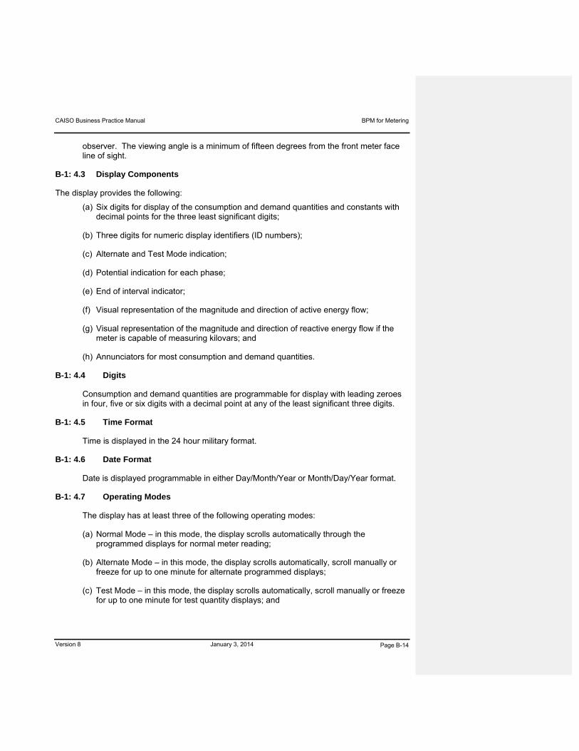
CAISO Business Practice Manual BPM for Metering
Version 8 January 3, 2014 Page B-14
observer. The viewing angle is a minimum of fifteen degrees from the front meter face line of sight.
B-1: 4.3 Display Components
The display provides the following:
(a) Six digits for display of the consumption and demand quantities and constants with decimal points for the three least significant digits;
(b) Three digits for numeric display identifiers (ID numbers);
(c) Alternate and Test Mode indication;
(d) Potential indication for each phase;
(e) End of interval indicator;
(f) Visual representation of the magnitude and direction of active energy flow;
(g) Visual representation of the magnitude and direction of reactive energy flow if the meter is capable of measuring kilovars; and
(h) Annunciators for most consumption and demand quantities.
B-1: 4.4 Digits
Consumption and demand quantities are programmable for display with leading zeroes in four, five or six digits with a decimal point at any of the least significant three digits.
B-1: 4.5 Time Format
Time is displayed in the 24 hour military format.
B-1: 4.6 Date Format
Date is displayed programmable in either Day/Month/Year or Month/Day/Year format.
B-1: 4.7 Operating Modes
The display has at least three of the following operating modes:
(a) Normal Mode – in this mode, the display scrolls automatically through the programmed displays for normal meter reading;
(b) Alternate Mode – in this mode, the display scrolls automatically, scroll manually or freeze for up to one minute for alternate programmed displays;
(c) Test Mode – in this mode, the display scrolls automatically, scroll manually or freeze for up to one minute for test quantity displays; and

CAISO Business Practice Manual BPM for Metering
Version 8 January 3, 2014 Page B-15
(d) Segment Check – in this mode, all segments or displays are activated to verify display integrity.
Display ID numbers and display sequence are independently programmable for each of the modes referred to above. Display times are programmable.
B-1: 4.8 Normal Mode
Upon power-up, the meter display operates in the Normal Mode. The meter display operates in Normal Mode until power is disconnected or until either the Alternate Mode or the Test Mode is activated.
B-1: 4.9 Alternate Mode
The Alternate Mode is initiated with a display control device that does not require meter cover removal or with a meter programmer connected to the optical port.
Display Items
As a minimum, the meter provides the display quantities and items for each of the modes referred to in Section B-1: 4.7 as detailed in Attachment 2.
B-1: 4.10 Constants and Correction Factors.
The meter has programmable multi-variable polynomial function multipliers and/or summers to account for instrument transformer ratios, instrument transformer correction factors, the meter constant, line losses and power transformer loss correction.
B-1: 4.11 Identifiers
The meter has programmable identifiers for the meter ID, the person who programmed the meter (programmer ID) and the current program ID. The meter ID shall be capable of eight numeric characters.
B-1: 5 METER DIAGNOSTICS
B-1: 5.1 Self-test
The meter register is capable of performing a self-test of the register software. As a minimum, the self-test is performed at the following times:
(a) Whenever communications are established to the register;
(b) After a power-up; and
(c) Once per day.

CAISO Business Practice Manual BPM for Metering
Version 8 January 3, 2014 Page B-16
B-1: 5.2 Diagnostic Checks
As a minimum, the following diagnostic checks are performed during a self-test:
(a) Check the backup battery capacity;
(b) Verify the program integrity; and
(c) Verify the memory integrity.
B-1: 5.3 Data Overrun
The register is capable of detecting that the maximum amount of data has been exceeded during a demand interval.
B-1: 5.4 Error and Warning Displays
Meters are capable of the following displays:
(a) Any detected error or warning is stored in memory and an error or warning code displayed on the display;
(b) Error code displays freeze the display; and
(c) Warning code displays are programmable to one of the following choices:
i. Freeze the warning code on the display; or
ii. Warning code display at the end of the Normal, Alternate or Test Modes display sequences.
B-1: 5.5 Error Reset
Error or warning conditions are only reset upon an explicit command invoked via the meter programmer or upon some other explicit action by CAISO.
B-1: 6 PROGRAMMING AND SOFTWARE
The programming software is tested at CAISO and approved by the CAISO Meter Engineering.
B-1: 6.1 Optical Communications Interface.
The meter is capable of communicating with a personal computer through the optical port at a minimum.

CAISO Business Practice Manual BPM for Metering
Version 8 January 3, 2014 Page B-17
B-1: 6.2 Meter Programmers
The CAISO and CAISO Authorized Inspectors are suggested to use Windows based laptops (PC). Field communications with the meter normally is through the optical port, as an option; Ethernet cable, Rs232-Rs 485, or phone modem can be used.
B-1: 6.3 Meter Program
The CAISO meters through the meter manufacturer ensure its supplier provides a meter program software package for use by the CAISO Meter Engineers. The meter program in conjunction with a laptop computer must be capable of loading all meter operating parameters as well as setting time and passwords into the meter.
B-1: 6.4 Field Program Functions
The Field Program as a minimum provides the following functions:
(a) Set date, time and passwords on the meter;
(b) Preset the meter consumption registers;
(c) Send and receive configurations to and from the meter;
(d) Compare configuration files from the meter with desired files and report discrepancies;
(e) Read meter billing data and load profile data;
(f) Generate Meter Data and diagnostic reports for printing;
(g) Read, display and modify the present settings of field configurable items;
(h) Execute a billing period reset;
(i) Reset all consumption and demand quantities; and
B-1: 6.5 Operating System
All software programs shall utilize industry standard operating system software. The operating system software must be currently supported by the software vendor that produces and maintains it. The CAISO requires these programs to maintain operating system compatibility with the CAISO corporate computing standards. The Rate Development, Field, and Field Disk Serialization Programs must be capable of running under CAISO standardized operating systems without any loss of function.
B-1: 6.6 Communication Protocol
The protocol used for communication with the meter through optical port, Ethernet, RS-232, RS485, or the phone modem.

CAISO Business Practice Manual BPM for Metering
Version 8 January 3, 2014 Page B-18
B-1: 6.7 Optical Probe
The meter program supports use of a compatible optical probe connected to the standard PC.
B-1: 7 COMMUNICATION
B-1: 7.1 Optical Port
The primary communication port to the meter for reading and programming of the internal data is an optically isolated communication port per ANSI C12.13, Type 2 or other serial port.
B-1: 7.2 Baud Rate
The optical port communicates at a minimum of 9600 baud.
B-1: 7.3 Optical Port Location
The optical port is located in the front of the meter and is accessible without removing the meter’s cover. The optical port must be functional with the meter cover removed.
B-1: 7.4 Optical Port Cable
There is to be no cable connection between the optical port on the meter cover and the register.
B-1: 7.5 RS232 or RS 485 or RSXXX.
One RSXXX port is provided at the meter for bi-directional communications (with security provisions included) to computers and/or data acquisition devices. The meter must have the capability for being polled every 5 minutes for data by RMDAPS. An optional RSXXX port or ports with read-only access can be provided for others desiring the data. All RSXXX ports are optically isolated.
The meter supports and is implementable with CAISO secure communication system chains, including Meter RSXXX port through CAISO approved communication network to RMDAPS.
B-1: 8 OPTIONAL METER FUNCTIONS
B-1: 8.1 Internal Modem
CAISO may specify an internal modem having telephone communications at autobaud rates of up to 115000 baud. The modem includes automatic baud select, configurable answer time window and configurable answer counter ring. The ring detect circuitry is affected by spurious voltage rises in the telephone line.

CAISO Business Practice Manual BPM for Metering
Version 8 January 3, 2014 Page B-19
B-1: 9 ACCURACY
B-1: 9.1 ANSI C12.10
The meter meets or exceeds the accuracy specifications contained in ANSI C12.10 over its entire service life without the need for adjustment.
B-1: 9.2 Factory Calibration
The meter is calibrated to provide the following level of accuracy:
(a) 0.2% at full load at power factor of 100%;
(b) 0.25% at full load at power factor of 50% lag;
(c) 0.25% at full load power factor at 50% lead; and
(d) 0.25% at light load at power factor of 100%.
B-1: 9.3 Test Equipment
Meter accuracy and calibration tests, both shop and field, require only standard test equipment that have accuracy of at least plus or minus 0.05% or better. The meter standard is a very accurate energy meter of substantially greater accuracy than the revenue billing meter being tested, or five times greater in accuracy. All the meters used on the CAISO system are required to have accuracy of at least plus or minus 0.25%. No special laboratory-type test equipment or test procedures are required to assure accuracy of the meter.
B-1: 9.4 Creep
The meter may not creep. No data registration can occur for any consumption or demand while the current circuit is open.
B-1: 9.5 Starting Current
The meter starts to calculate consumption and demand quantities when the per-phase current reaches 5 milliamps.
B-1: 9.6 Start-up Delay
The meter starts to calculate consumption and demand quantities less than 3 seconds after power application.
B-1: 9.7 Data Output
Data output has the same accuracy as the meter displays.
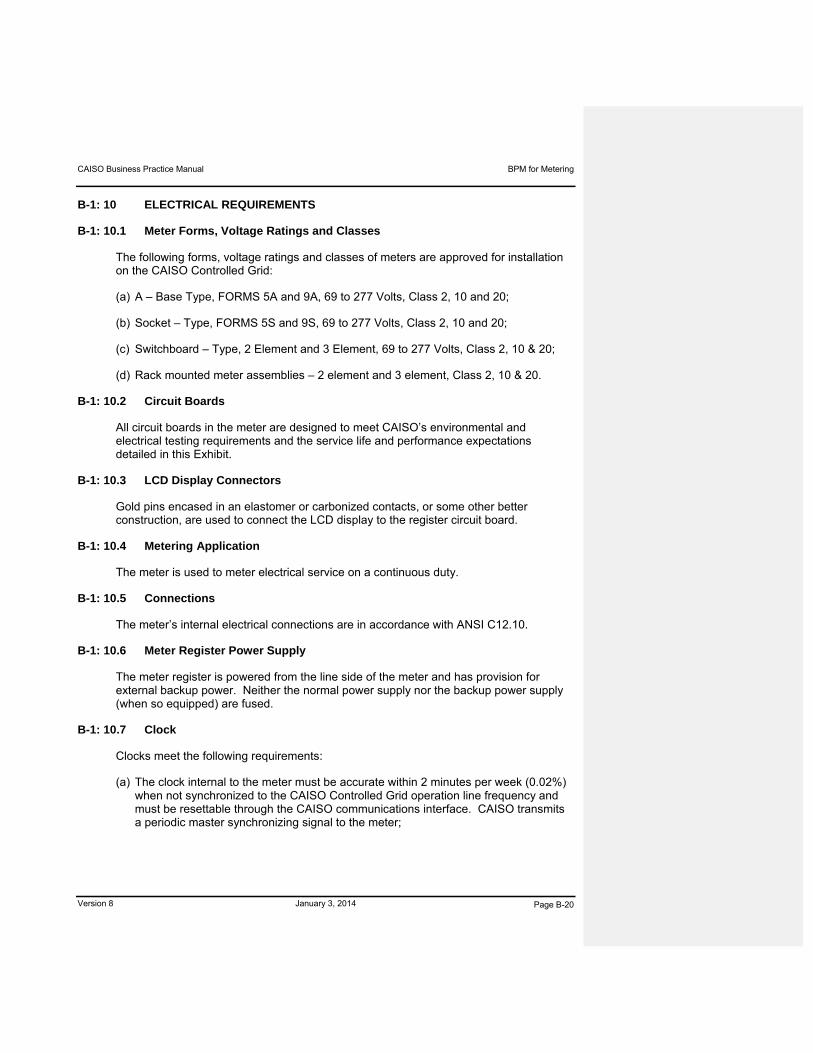
CAISO Business Practice Manual BPM for Metering
Version 8 January 3, 2014 Page B-20
B-1: 10 ELECTRICAL REQUIREMENTS
B-1: 10.1 Meter Forms, Voltage Ratings and Classes
The following forms, voltage ratings and classes of meters are approved for installation on the CAISO Controlled Grid:
(a) A – Base Type, FORMS 5A and 9A, 69 to 277 Volts, Class 2, 10 and 20;
(b) Socket – Type, FORMS 5S and 9S, 69 to 277 Volts, Class 2, 10 and 20;
(c) Switchboard – Type, 2 Element and 3 Element, 69 to 277 Volts, Class 2, 10 & 20;
(d) Rack mounted meter assemblies – 2 element and 3 element, Class 2, 10 & 20.
B-1: 10.2 Circuit Boards
All circuit boards in the meter are designed to meet CAISO’s environmental and electrical testing requirements and the service life and performance expectations detailed in this Exhibit.
B-1: 10.3 LCD Display Connectors
Gold pins encased in an elastomer or carbonized contacts, or some other better construction, are used to connect the LCD display to the register circuit board.
B-1: 10.4 Metering Application
The meter is used to meter electrical service on a continuous duty.
B-1: 10.5 Connections
The meter’s internal electrical connections are in accordance with ANSI C12.10.
B-1: 10.6 Meter Register Power Supply
The meter register is powered from the line side of the meter and has provision for external backup power. Neither the normal power supply nor the backup power supply (when so equipped) are fused.
B-1: 10.7 Clock
Clocks meet the following requirements:
(a) The clock internal to the meter must be accurate within 2 minutes per week (0.02%) when not synchronized to the CAISO Controlled Grid operation line frequency and must be resettable through the CAISO communications interface. CAISO transmits a periodic master synchronizing signal to the meter;
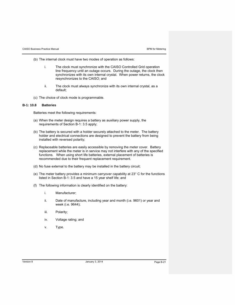
CAISO Business Practice Manual BPM for Metering
Version 8 January 3, 2014 Page B-21
(b) The internal clock must have two modes of operation as follows:
i. The clock must synchronize with the CAISO Controlled Grid operation line frequency until an outage occurs. During the outage, the clock then synchronizes with its own internal crystal. When power returns, the clock resynchronizes to the CAISO; and
ii. The clock must always synchronize with its own internal crystal, as a default;
(c) The choice of clock mode is programmable.
B-1: 10.8 Batteries
Batteries meet the following requirements:
(a) When the meter design requires a battery as auxiliary power supply, the requirements of Section B-1: 3.5 apply;
(b) The battery is secured with a holder securely attached to the meter. The battery holder and electrical connections are designed to prevent the battery from being installed with reversed polarity;
(c) Replaceable batteries are easily accessible by removing the meter cover. Battery replacement while the meter is in service may not interfere with any of the specified functions. When using short life batteries, external placement of batteries is recommended due to their frequent replacement requirement.
(d) No fuse external to the battery may be installed in the battery circuit;
(e) The meter battery provides a minimum carryover capability at 23° C for the functions listed in Section B-1: 3.5 and have a 15 year shelf life; and
(f) The following information is clearly identified on the battery:
i. Manufacturer;
ii. Date of manufacture, including year and month (i.e. 9601) or year and week (i.e. 9644);
iii. Polarity;
iv. Voltage rating; and
v. Type.
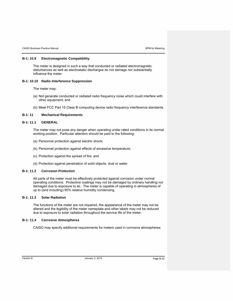
CAISO Business Practice Manual BPM for Metering
Version 8 January 3, 2014 Page B-22
B-1: 10.9 Electromagnetic Compatibility
The meter is designed in such a way that conducted or radiated electromagnetic disturbances as well as electrostatic discharges do not damage nor substantially influence the meter.
B-1: 10.10 Radio Interference Suppression
The meter may:
(a) Not generate conducted or radiated radio frequency noise which could interfere with other equipment; and
(b) Meet FCC Part 15 Class B computing device radio frequency interference standards.
B-1: 11 Mechanical Requirements
B-1: 11.1 GENERAL
The meter may not pose any danger when operating under rated conditions in its normal working position. Particular attention should be paid to the following:
(a) Personnel protection against electric shock;
(b) Personnel protection against effects of excessive temperature;
(c) Protection against the spread of fire; and
(d) Protection against penetration of solid objects, dust or water.
B-1: 11.2 Corrosion Protection
All parts of the meter must be effectively protected against corrosion under normal operating conditions. Protective coatings may not be damaged by ordinary handling nor damaged due to exposure to air. The meter is capable of operating in atmospheres of up to (and including) 95% relative humidity condensing.
B-1: 11.3 Solar Radiation
The functions of the meter are not impaired, the appearance of the meter may not be altered and the legibility of the meter nameplate and other labels may not be reduced due to exposure to solar radiation throughout the service life of the meter.
B-1: 11.4 Corrosive Atmospheres
CAISO may specify additional requirements for meters used in corrosive atmospheres.
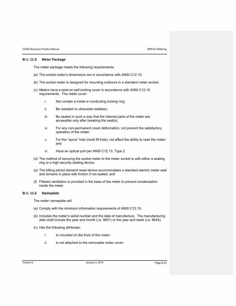
CAISO Business Practice Manual BPM for Metering
Version 8 January 3, 2014 Page B-23
B-1: 11.5 Meter Package
The meter package meets the following requirements:
(a) The socket meter’s dimensions are in accordance with ANSI C12.10;
(b) The socket meter is designed for mounting outdoors in a standard meter socket;
(c) Meters have a twist-on self-locking cover in accordance with ANSI C12.10 requirements. The meter cover:
i. Not contain a metal or conducting locking ring;
ii. Be resistant to ultraviolet radiation;
iii. Be sealed in such a way that the internal parts of the meter are accessible only after breaking the seal(s);
iv. For any non-permanent cover deformation, not prevent the satisfactory operation of the meter;
v. For the “sprue” hole (mold fill hole), not affect the ability to read the meter; and
vi. Have an optical port per ANSI C12.13, Type 2.
(d) The method of securing the socket meter to the meter socket is with either a sealing ring or a high security sealing device;
(e) The billing period demand reset device accommodates a standard electric meter seal and remains in place with friction if not sealed; and
(f) Filtered ventilation is provided in the base of the meter to prevent condensation inside the meter.
B-1: 11.6 Nameplate
The meter nameplate will:
(a) Comply with the minimum information requirements of ANSI C12.10;
(b) Includes the meter’s serial number and the date of manufacture. The manufacturing date shall include the year and month (i.e. 9601) or the year and week (i.e. 9644);
(c) Has the following attributes:
i. Is mounted on the front of the meter;
ii. Is not attached to the removable meter cover;

CAISO Business Practice Manual BPM for Metering
Version 8 January 3, 2014 Page B-24
iii. Is readable when the meter is installed in the meter socket or panel; and
iv. Does will not impair access for accuracy adjustment or field replacement of components (such as the battery).
(d) Includes ANSI standard bar coding; and
(e) Includes an easily erasable strip with minimum dimensions of 3/8 inch by 1½ inches for penciling in items such as meter multiplier or the meter tester’s initials.
B-1: 12 SECURITY
B-1: 12.1 Billing Period Reset
Operation of the billing period demand reset mechanism requires breaking of a mechanical sealing device. Use of common utility-type sealing devices are accommodated.
B-1: 12.2 Meter Password
The meter is programmable by the meter programmer with up to four unique passwords to prevent unauthorized tampering by use of the optical port or the optional modem. Passwords must be a minimum of four (4) alpha/numeric characters. Access rights and capabilities are individually programmable for each password. Passwords can also be changed via MV-90 translation module.
B-1: 12.3 Test Mode
Removal of the meter cover or a software command using a password is required to activate the Test Mode.
B-1: 12.4 Program Security
At least four levels of security are available for the meter program. These levels include:
(a) Read Register— the user can only read billing and load profile data;
(b) Read Register— the user can only read billing and load profile data, and perform a billing period reset;
(c) Read/Modify Register— the user can perform functions listed in 12.4(a) and 12.4(b), plus download meter configuration files and operate other features of the meter program; and
(d) Read/Modify/Program Register— the user can perform functions listed in 12.4(a), 12.4(b) and 12.4(c), plus develop meter configuration files and operate additional features of the meter program.

CAISO Business Practice Manual BPM for Metering
Version 8 January 3, 2014 Page B-25
B-1: 12.5 Revenue Protection
Meters that help prevent Energy diversion are preferred.
B-1: 13 METER APPROVAL TESTING
B-1: 13.1 General Requirement
This Section outlines the testing required by CAISO to assure the quality of meters, CAISO does not approve meters that have not undergone the testing referred to in this Section.
CAISO Testing using NIST Traceable Laboratory
In addition to the required manufacturer testing specified in this Section, CAISO reserves the right to require a NIST traceable laboratory test data resulting from the performance of tests as outlined in this Section.
In addition to the applicable testing requirements of the ANSI C12 standards, the qualification tests specified in this Section are conducted to confirm correct operation of the meter. The qualification testing is required for new meter designs and for meter product changes.
The NIST traceable laboratory ensures that it provides a certified test report documenting the tests and their results. The test report is signed by the NIST traceable laboratory and includes all charts, graphs and data recorded during testing.
B-1: 13.2 Meter Failure Definition
A meter is designated as failed if any of the following events occur:
(a) Failure of the meter to perform all of the specified functions;
(b) Failure of the meter to meet the technical performance specifications included in this Exhibit;
(c) Signs of physical damage or performance degradation as a result of a test procedure, including effects which could shorten the service life of the meter;
(d) The occurrence of an unexpected change of state, loss of data or other unacceptable mode of operation for the meter as a consequence of a test procedure; and
(e) Failures are classified as a hardware, firmware or software failure or a combination according to the following definitions:
i. Firmware failures are errors made during the fabrication of programmable read only memory (PROM) chips such that the required program or instruction set that the microprocessor is to perform is incorrect;
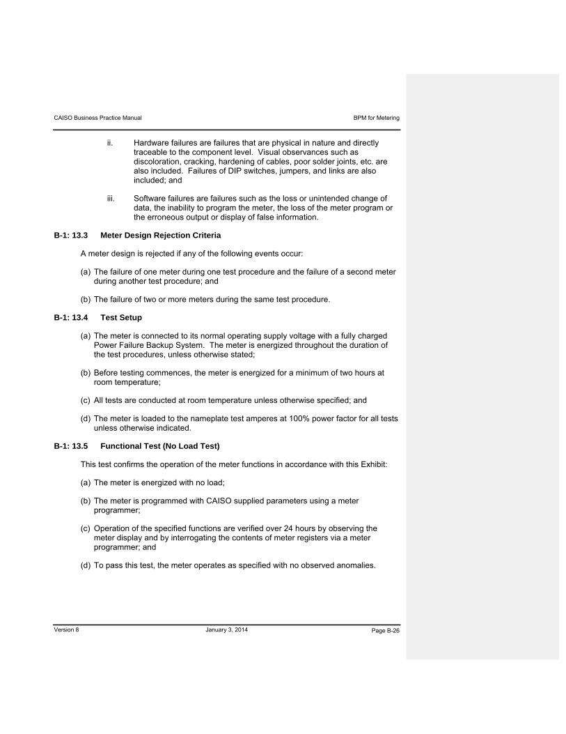
CAISO Business Practice Manual BPM for Metering
Version 8 January 3, 2014 Page B-26
ii. Hardware failures are failures that are physical in nature and directly traceable to the component level. Visual observances such as discoloration, cracking, hardening of cables, poor solder joints, etc. are also included. Failures of DIP switches, jumpers, and links are also included; and
iii. Software failures are failures such as the loss or unintended change of data, the inability to program the meter, the loss of the meter program or the erroneous output or display of false information.
B-1: 13.3 Meter Design Rejection Criteria
A meter design is rejected if any of the following events occur:
(a) The failure of one meter during one test procedure and the failure of a second meter during another test procedure; and
(b) The failure of two or more meters during the same test procedure.
B-1: 13.4 Test Setup
(a) The meter is connected to its normal operating supply voltage with a fully charged Power Failure Backup System. The meter is energized throughout the duration of the test procedures, unless otherwise stated;
(b) Before testing commences, the meter is energized for a minimum of two hours at room temperature;
(c) All tests are conducted at room temperature unless otherwise specified; and
(d) The meter is loaded to the nameplate test amperes at 100% power factor for all tests unless otherwise indicated.
B-1: 13.5 Functional Test (No Load Test)
This test confirms the operation of the meter functions in accordance with this Exhibit:
(a) The meter is energized with no load;
(b) The meter is programmed with CAISO supplied parameters using a meter programmer;
(c) Operation of the specified functions are verified over 24 hours by observing the meter display and by interrogating the contents of meter registers via a meter programmer; and
(d) To pass this test, the meter operates as specified with no observed anomalies.
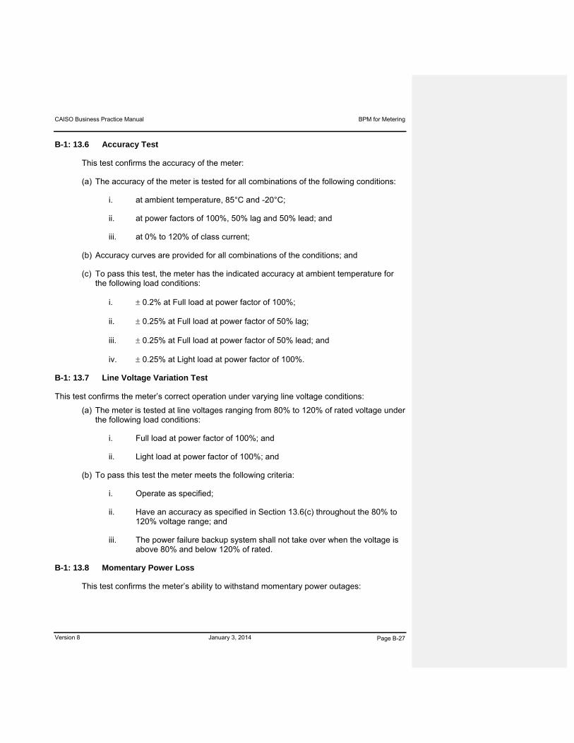
CAISO Business Practice Manual BPM for Metering
Version 8 January 3, 2014 Page B-27
B-1: 13.6 Accuracy Test
This test confirms the accuracy of the meter:
(a) The accuracy of the meter is tested for all combinations of the following conditions:
i. at ambient temperature, 85°C and -20°C;
ii. at power factors of 100%, 50% lag and 50% lead; and
iii. at 0% to 120% of class current;
(b) Accuracy curves are provided for all combinations of the conditions; and
(c) To pass this test, the meter has the indicated accuracy at ambient temperature for the following load conditions:
i. 0.2% at Full load at power factor of 100%;
ii. 0.25% at Full load at power factor of 50% lag;
iii. 0.25% at Full load at power factor of 50% lead; and
iv. 0.25% at Light load at power factor of 100%.
B-1: 13.7 Line Voltage Variation Test
This test confirms the meter’s correct operation under varying line voltage conditions:
(a) The meter is tested at line voltages ranging from 80% to 120% of rated voltage under the following load conditions:
i. Full load at power factor of 100%; and
ii. Light load at power factor of 100%; and
(b) To pass this test the meter meets the following criteria:
i. Operate as specified;
ii. Have an accuracy as specified in Section 13.6(c) throughout the 80% to 120% voltage range; and
iii. The power failure backup system shall not take over when the voltage is above 80% and below 120% of rated.
B-1: 13.8 Momentary Power Loss
This test confirms the meter’s ability to withstand momentary power outages:

CAISO Business Practice Manual BPM for Metering
Version 8 January 3, 2014 Page B-28
(a) The test is performed by opening the AC power supply input for the specified duration;
(b) Twelve tests are conducted using the following sequence:
i. Energize the meter;
ii. Simulate a power loss of 0.5 cycles at 60 hertz;
iii. Lengthen each succeeding simulated power outage by 0.5 cycles until a duration of 6.0 cycles is attained; and
iv. The start of each successive test shall be delayed by one minute; and
(c) To pass this test, the meter operates as specified with no observed anomalies.
B-1: 13.9 Power Failure Backup System Test
This test confirms the carryover capability of the power failure backup system:
(a) This test is conducted at ambient temperature using a new or fully charged battery;
(b) The test is conducted using the following sequence:
i. Energize the meter at full load for two hours;
ii. De-energize the meter for 24 hours; and
iii. Verify the integrity of programs and metering data stored in memory; and
(c) To pass this test, the meter operates as specified with no observed anomalies.
B-1: 13.10 Brownout and Extended Low Voltage Test
This test confirms the meter’s ability to withstand brownouts and extended low voltage conditions:
(a) The test is conducted using the following sequence:
i. Energize the meter and verify correct operation;
ii. Slowly lower the line voltage to 80% of nominal;
iii. Operate the meter at this voltage level for 6 hours;
iv. Verify correct meter operation;
v. Lower the line voltage to 50% of nominal;
vi. Operate the meter at this voltage level for 6 hours; and

CAISO Business Practice Manual BPM for Metering
Version 8 January 3, 2014 Page B-29
vii. Verify correct operation of the meter and the power failure backup system; and
(b) To pass this test, the meter operates as specified with no observed anomalies.
B-1: 13.11 Effect of Power Failure Backup System Voltage Variation on Clock Accuracy
This test confirms the effects of the battery voltage on the meter’s clock accuracy:
(a) The meter is tested with the battery disconnected and an auxiliary DC power supply connected to the battery carryover circuit. The DC power may be varied from 95% to 105% of nominal battery voltage; and
(b) To pass this test, the accuracy of the meter clock must be within 0.02% (2 minutes per week) with a voltage variation of 5 % of nominal battery voltage at ambient temperature.
B-1: 13.12 Effect of Temperature Variation on Clock Accuracy
This test confirms the effects of temperature on the meter clock accuracy:
(a) This test is conducted with the register in the battery carryover mode;
(b) The temperature may be varied from 85°C to –20°C;
(c) The meter is exposed to each temperature for a least 2 hours prior to testing; and
(d) To pass this test, the accuracy of the meter clock must be within 0.02% (2 minutes per week) at ambient temperature, 85°C, and -20°C.
B-1: 13.13 Temperature Cycle Test
This test confirms the effects of an accelerated temperature cycle on the meter:
(a) The meter cover must be removed during this test;
(b) The test duration is 7 days (168 hours);
(c) The temperature is cycled once per 24 hour period;
(d) Temperature is varied linearly during the tests at a constant rate not to exceed 20°C per hour;
(e) Humidity is not controlled during the test;
(f) The meter must be de-energized during the fourth and fifth cycles of the test to verify the performance of the power failure backup system during temperature fluctuations;
(g) Each 24 hour cycle consists of the following:

CAISO Business Practice Manual BPM for Metering
Version 8 January 3, 2014 Page B-30
i. Begin test at +20°C (or room temperature if within 5°C);
ii. Ramp up to +85°C in approximately 3.25 hours;
iii. Hold at +85°C for approximately 10.75 hours;
iv. Ramp down to -20 C in approximately 5.25 hours;
v. Hold at -20°C for approximately 2.75 hours;
vi. Ramp up to +20°C in approximately 2.00 hours; and
vii. Begin next 24 hour cycle or end test after 7 cycles; and
(h) To pass this test, the meter operates as specified with no observed anomalies for the entire test period.
B-1: 13.14 Humidity Cycle Test
This test confirms the effects of an accelerated humidity cycle on the meter:
(a) The meter cover is removed during this test, or a meter cover with a large hole at the bottom may be substituted;
(b) The duration of the test is 24 hours;
(c) Condensation may form on the meter during the test;
(d) Temperature may be varied linearly during the tests at a constant rate not to exceed 20°C per hour;
(e) Humidity may not be controlled during temperature changes;
(f) The test consists of the following sequence:
i. Begin at +20°C (or room temperature if within 5°C);
ii. Ramp up to +85°C in approximately 3.25 hours;
iii. Ramp up to a relative humidity of 95% in approximately 1 hour;
iv. Hold at +85°C at a relative humidity of 95% ±1% for approximately 14.5 hours;
v. Ramp down to +20°C in approximately 3.25 hours;
vi. Concurrently with Section 13.14(f)v. ramp down to a relative humidity of 75% in approximately 15 minutes;

CAISO Business Practice Manual BPM for Metering
Version 8 January 3, 2014 Page B-31
vii. Hold relative humidity at 75% for remainder of temperature ramp down; and
viii. Hold at 20°C at a relative humidity of 75% ±1% for approximately 2 hours; and
(g) To pass this test, the meter operates as specified with no observed anomalies for the entire test period.
B-1: 13.15 Insulation Withstand Test
This test confirms the insulation levels of the meter:
(a) The meter may not be energized for this test;
(b) The insulation between power line voltage and current carrying parts and any other metallic or conductive part may be tested by applying 2500 volts rms, 60 Hz for a period of one minute; and
(c) To pass this test the leakage current may not exceed one milliamp for the duration of the test and the meter shall operate after completion of the test.
B-1: 13.16 Standard Waveform Surge Withstand Test
This test confirms the ability of the meter to withstand voltage transients:
(a) The meter is energized but not loaded during the test;
(b) The test is conducted in accordance with the latest recognized industry standards;
(c) The oscillatory test wave is applied at a repetition rate of 100 tests per second for 25 seconds;
(d) The test signal is applied in both the common and transverse modes;
(e) The test is conducted on all voltage, current, and optional equipment inputs and outputs;
(f) This test is performed two times with a maximum period of 1 minute between tests; and
(g) To pass this test, the meter operates as specified with no observed anomalies;
B-1: 13.17 Fast Transient Waveform Surge Withstand Test
This test confirms the ability of the meter to withstand fast voltage transients:
(a) The meter is energized but not loaded during the test;
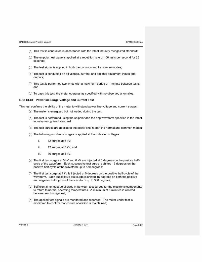
CAISO Business Practice Manual BPM for Metering
Version 8 January 3, 2014 Page B-32
(b) This test is conducted in accordance with the latest industry recognized standard;
(c) The unipolar test wave is applied at a repetition rate of 100 tests per second for 25 seconds;
(d) The test signal is applied in both the common and transverse modes;
(e) The test is conducted on all voltage, current, and optional equipment inputs and outputs;
(f) This test is performed two times with a maximum period of 1 minute between tests; and
(g) To pass this test, the meter operates as specified with no observed anomalies.
B-1: 13.18 Powerline Surge Voltage and Current Test
This test confirms the ability of the meter to withstand power line voltage and current surges:
(a) The meter is energized but not loaded during the test;
(b) The test is performed using the unipolar and the ring waveform specified in the latest industry recognized standard;
(c) The test surges are applied to the power line in both the normal and common modes;
(d) The following number of surges is applied at the indicated voltages:
i. 12 surges at 6 kV;
ii. 12 surges at 5 kV; and
iii. 36 surges at 4 kV.
(e) The first test surges at 5 kV and 6 kV are injected at 0 degrees on the positive half-cycle of the waveform. Each successive test surge is shifted 15 degrees on the positive half-cycle of the waveform up to 180 degrees;
(f) The first test surge at 4 kV is injected at 0 degrees on the positive half-cycle of the waveform. Each successive test surge is shifted 15 degrees on both the positive and negative half-cycles of the waveform up to 360 degrees;
(g) Sufficient time must be allowed in between test surges for the electronic components to return to normal operating temperatures. A minimum of 5 minutes is allowed between each surge test;
(h) The applied test signals are monitored and recorded. The meter under test is monitored to confirm that correct operation is maintained;

CAISO Business Practice Manual BPM for Metering
Version 8 January 3, 2014 Page B-33
(i) After the tests each meter is inspected for visible damage, such as signs of arcing, etc.; and
(j) To pass this test, the meter operates as specified with no visible damage observed.
B-1: 13.19 Electrostatic Susceptibility Test
This test verifies the ability of the meter to withstand electrostatic discharges:
(a) This test is tested in accordance with the latest revision of Military Handbook DOD-HDBK-263;
(b) The test generator simulates a human body with a capacitance of 100 picofarads and a series resistance of 1500 ohms;
(c) The test probe is a 3/8 inch rod with a rounded tip;
(d) The following procedures are followed:
i. Test all surfaces, including switches and buttons and other components that are contacted by personnel under normal handling, installation and use of the meter. This includes any safety grounded or neutral terminals on the exterior of the meter enclosure;
ii. With the test probe voltage set at 10 kV, contact each of the above surfaces with the probe;
iii. With the test probe voltage set to 15 kV, locate the probe to within approximately 0.5 inch (avoiding contact) with each of the above surfaces; and
iv. The functions of the meter are periodically verified for correct operation; and
(e) To pass this test, the meter operates as specified with no observed anomalies.
B-1: 13.20 Visual Inspection
This test is performed after all of the other tests except the shipping test have been performed:
(a) Visual inspection is performed for all electronic circuit boards in the meter; and
(b) To pass this test, the meter may not have any defect which would result in rejection under the latest recognized industry standards on any electronic circuit board.

CAISO Business Practice Manual BPM for Metering
Version 8 January 3, 2014 Page B-34
B-1: 13.21 Shipping Test
This test confirms the ability of the meter and its packaging to withstand the rigors of shipping and handling:
(a) The meter may not be energized during this test, but may be programmed and operating in the power backup mode;
(b) The packaged meter is subjected to the following tests:
i. the National/International Safe Transit Association Pre-shipment Test Procedures, Project lA; and
ii. Method B, Single Container Resonance Test, of the latest revision of American Society for Testing and Materials (ASTM) Standard D-999. Test intensities, frequency ranges and test durations meet or exceed the recommended values of ASTM D-999; and
(c) To pass this test, the meter is inspected and tested to verify that no damage occurred and that the time and all stored data is correct.
B-1: 14 SAFETY
B-1: 14.1 Hazardous Voltage
Hazardous voltages are not easily accessible with the meter cover removed.
B-1: 14.2 Grounding
All accessible conductive parts on the exterior of the meter and conductive parts that are accessible upon removal of the meter cover are be electrically connected to the meter grounding tabs. All connections in the grounding circuit are made with an effective bonding technique.
B-1: 14.3 Toxic Materials
No materials that are toxic to life or harmful to the environment are exposed in the meter during normal use.
B-1: 14.4 Fire Hazard
Materials used in the construction of the meter do not create a fire hazard.
B-1: 15 DATA SECURITY AND PERFORMANCE
(a) Manual access for changing data or reprogramming requires the physical removal or breaking of a CAISO seal by CAISO or a CAISO Authorized Inspector.
(b) No loss of data may occur as a result of the following events within design specifications:

CAISO Business Practice Manual BPM for Metering
Version 8 January 3, 2014 Page B-35
i. Power outages, frequency changes, transients, harmonics, reprogramming, reading; and
ii. Environmental factors—dampness, heat, cold, vibration, dust.
(c) 5-minute interval data for all channels for the most recent 60-day period is always available and accessible via the communications interface or the optical interface.
B-1: 16 DOCUMENTATION
B-1: 16.1 Hardware Documentation to Be Provided For CAISO Review
(a) Drawing(s) showing the external meter connections.
(b) Instruction booklets detailing the necessary procedures and precautions for installation of the meter provided for use by field personnel during initial installation written in the style of a step-by-step outline.
(c) One (1) technical/maintenance manual and one (1) repair manual provided for each meter style. These manuals must be sufficiently detailed so that circuit operation can be understood and equipment repair facilitated.
(d) The above documents must be submitted for approval by CAISO. Approval of documents by CAISO does not relieve any responsibility for complying with all the requirements of this Exhibit.
B-1: 16.2 Software
A complete set of manuals detailing the operation of the meter program and programming software is provided to CAISO. These manuals must explain to a person with only basic computer knowledge how to generate and download meter configuration files.
B-1: 17 APPLICABLE STANDARDS
The standards referred to in Attachment A of this BPM apply to all meters.
B-1: 18 DEFINITIONS
The following terms and expressions used in this Exhibit are detailed as set forth below:
“ambient temperature” means temperature of 23°±2° Celsius.
“average power factor” means the power factor calculated using the average active and reactive power flows over the latest demand interval.
“delivered” means Energy (active, reactive, or apparent) that flows from the CAISO Controlled Grid to an End-User.
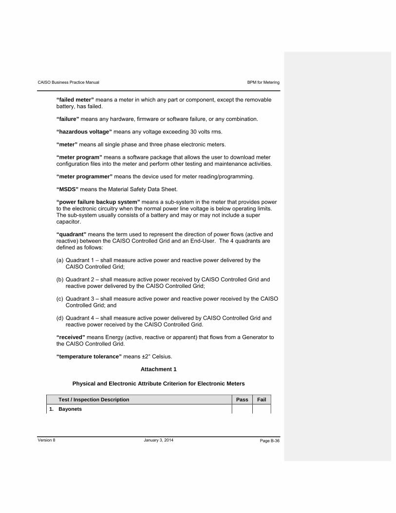
CAISO Business Practice Manual BPM for Metering
Version 8 January 3, 2014 Page B-36
“failed meter” means a meter in which any part or component, except the removable battery, has failed.
“failure” means any hardware, firmware or software failure, or any combination.
“hazardous voltage” means any voltage exceeding 30 volts rms.
“meter” means all single phase and three phase electronic meters.
“meter program” means a software package that allows the user to download meter configuration files into the meter and perform other testing and maintenance activities.
“meter programmer” means the device used for meter reading/programming.
“MSDS” means the Material Safety Data Sheet.
“power failure backup system” means a sub-system in the meter that provides power to the electronic circuitry when the normal power line voltage is below operating limits. The sub-system usually consists of a battery and may or may not include a super capacitor.
“quadrant” means the term used to represent the direction of power flows (active and reactive) between the CAISO Controlled Grid and an End-User. The 4 quadrants are defined as follows:
(a) Quadrant 1 – shall measure active power and reactive power delivered by the CAISO Controlled Grid;
(b) Quadrant 2 – shall measure active power received by CAISO Controlled Grid and reactive power delivered by the CAISO Controlled Grid;
(c) Quadrant 3 – shall measure active power and reactive power received by the CAISO Controlled Grid; and
(d) Quadrant 4 – shall measure active power delivered by CAISO Controlled Grid and reactive power received by the CAISO Controlled Grid.
“received” means Energy (active, reactive or apparent) that flows from a Generator to the CAISO Controlled Grid.
“temperature tolerance” means ±2° Celsius.
Attachment 1
Physical and Electronic Attribute Criterion for Electronic Meters
Test / Inspection Description Pass Fail
1. Bayonets
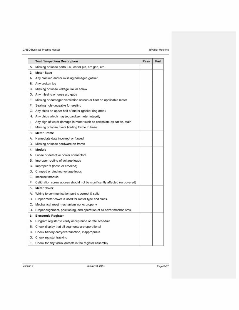
CAISO Business Practice Manual BPM for Metering
Version 8 January 3, 2014 Page B-37
Test / Inspection Description Pass Fail
A. Missing or loose parts, i.e., cotter pin, arc gap, etc.
2. Meter Base
A. Any cracked and/or missing/damaged gasket
B. Any broken leg
C. Missing or loose voltage link or screw
D. Any missing or loose arc gaps
E. Missing or damaged ventilation screen or filter on applicable meter
F. Sealing hole unusable for sealing
G. Any chips on upper half of meter (gasket ring area)
H. Any chips which may jeopardize meter integrity
I. Any sign of water damage in meter such as corrosion, oxidation, stain
J. Missing or loose rivets holding frame to base
3. Meter Frame
A. Nameplate data incorrect or flawed
B. Missing or loose hardware on frame
4. Module
A. Loose or defective power connectors
B. Improper routing of voltage leads
C. Improper fit (loose or crooked)
D. Crimped or pinched voltage leads
E. Incorrect module
F. Calibration screw access should not be significantly affected (or covered)
5. Meter Cover
A. Wiring to communication port is correct & solid
B. Proper meter cover is used for meter type and class
C. Mechanical reset mechanism works properly
D. Proper alignment, positioning, and operation of all cover mechanisms
6. Electronic Register
A. Program register to verify acceptance of rate schedule
B. Check display that all segments are operational
C. Check battery carryover function, if appropriate
D. Check register tracking
E. Check for any visual defects in the register assembly
CAISO Business Practice Manual BPM for Metering
Version 8 January 3, 2014 Page B-38
Only scratches and/or chips that are cosmetically or functionally objectionable are classified as
defective and failing.
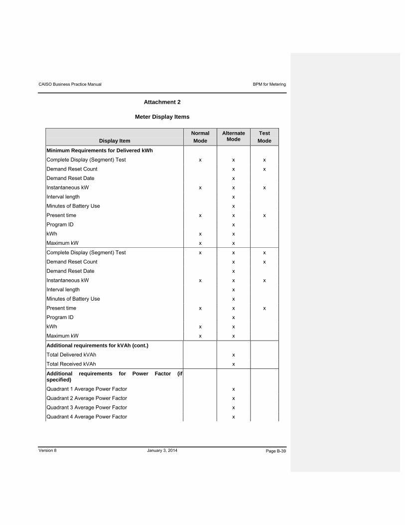
CAISO Business Practice Manual BPM for Metering
Version 8 January 3, 2014 Page B-39
Attachment 2
Meter Display Items
Display Item
Normal
Mode
Alternate Mode
Test
Mode
Minimum Requirements for Delivered kWh
Complete Display (Segment) Test x x x
Demand Reset Count x x
Demand Reset Date x
Instantaneous kW x x x
Interval length x
Minutes of Battery Use x
Present time x x x
Program ID x
kWh x x
Maximum kW x x
Complete Display (Segment) Test x x x
Demand Reset Count x x
Demand Reset Date x
Instantaneous kW x x x
Interval length x
Minutes of Battery Use x
Present time x x x
Program ID x
kWh x x
Maximum kW x x
Additional requirements for kVAh (cont.)
Total Delivered kVAh x
Total Received kVAh x
Additional requirements for Power Factor (if specified)
Quadrant 1 Average Power Factor x
Quadrant 2 Average Power Factor x
Quadrant 3 Average Power Factor x
Quadrant 4 Average Power Factor x

CAISO Business Practice Manual BPM for Metering
Version 8 January 3, 2014 Page B-40
Display Item
Normal
Mode
Alternate Mode
Test
Mode
Total Average Power Factor Delivered x
Total Average Power Factor Received x
CAISO Business Practice Manual BPM for Metering
Version 8 January 3, 2014 Page B-41
Exhibit B-2 to Section B
CAISO SPECIFICATION
FOR CERTIFICATION OF COUPLING CAPACITIVE VOLTAGE TRANSFORMER (CCVT),
OPTICAL SENSOR AND OIL-FILLED,
WOUND INSTRUMENT TRANSFORMERS
FOR CAISO REVENUE METERING

CAISO Business Practice Manual BPM for Metering
Version 8 January 3, 2014 Page B-42
B-2: 1 Purpose
This Exhibit specifies the technical requirements for reliable high-accuracy current transformers (CT) and voltage transformers (VT) to be used for revenue quality metering on the CAISO Controlled Grid. The CAISO instrument transformers must meet the applicable provisions of ANSI C57.13-1978 (R1986), in addition to the provisions in this Exhibit.
B-2: 2 Scope
B-2: 2.1 This Exhibit applies to the following:
Oil-filled, CCVT and Optical Sensor CTs & VTs.
All other CTs & VTs indoor or outdoor instrument transformers 10 kV BIL through 350 kv BIL (0.6 kv NSV through 69 KV NSV).
B-2: 2.2 This Exhibit applies only to the following above CTs & VTs, which are < 35kv and > 525kv must be individually specified in accordance with the engineered installations. This exhibit also applies to metering transformers.
B-2: 3 Standards
All instrument transformers covered by this Exhibit are designed, manufactured, tested and supplied in accordance with the applicable standards referred to in Attachment A of this BPM.
B-2: 4 Definitions
“hermetically sealed” means completely sealed by fusion, soldering, etc., so as to keep air or gas from getting in or out (i.e. airtight).
“metering unit” means one or more voltage element(s) and one or more current element(s) contained in one common housing.
“BIL rating” means basic lightning impulse insulation level.
“burden rating” means the total impedance (in ohms) that can be connected to the secondary circuit(s) of an instrument transformer while maintaining metering accuracy of plus-or-minus 0.3%
B-2: 5 Specifications
B-2: 5.1 General
All instrument transformers covered by this Exhibit have a minimum BIL rating appropriate for the designated nominal system voltage:
0.6 kV – 10 kV BIL

CAISO Business Practice Manual BPM for Metering
Version 8 January 3, 2014 Page B-43
4.8 kV – 14.4 kV – 60 kV BIL
25 kV – 125 kV BIL
34.5 kV – 200 kV BIL
60 - 69 kV – 350 kV BIL
115 kV – 550 kV BIL
230 kV – 900 kV BIL
525 kV – 1800 kV BIL
B-2: 5.2 Current Transformers
B-2: 5.2.1 Current transformer windings (typical configurations) are either:
(a) A single primary winding and single secondary winding with dual ratio tap;
(b) A dual primary winding and a single ratio tap;
(c) A single primary winding and one or more secondary windings with dual ratio tap(s); or
(d) Other combinations as available and approved by CAISO.
B-2: 5.2.2 Rated primary current
The rated primary current must be as specified by the CAISO Metered Entity.
B-2: 5.2.3 Rated secondary current
The rated secondary current must be 1 or 5 amperes @ rated primary current depending on the type of CT.
B-2: 5.2.4 Accuracy and burden
All current transformers have an accuracy and burden of:
(a) Standard – plus-or-minus 0.3% @ B0.1 - 1.8 ohms, 10% - 100% rated current; or
(b) Optional – plus-or-minus 0.15 % @ B0.1 - 1.8 ohms, 5% - 100 % rated current.
B-2: 5.2.5 Continuous current rating factor
All current transformers have a continuous current rating factor (or better) of:
(a) Standard – 1.5 @ 30 degrees C Ambient; or
CAISO Business Practice Manual BPM for Metering
Version 8 January 3, 2014 Page B-44
(b) Optional – 1.0 @ 30 degrees C Ambient.
B-2: 5.2.6 Short time thermal current rating
The short time thermal current rating varies with transformer rating as follows:
25/50: 5 ratio, 4 kA RMS to 1500/3000:5 ratio, 120 kA RMS.
B-2: 5.2.7 Mechanical short time current rating
The mechanical short time current rating varies with transformer rating as follows:
25/50:5 ratio, 3 kA RMS to 1500/3000:5 ratio, 90 kA RMS.
B-2: 5.3 Voltage Transformers
B-2: 5.3.1 Transformer windings consist of a single primary winding and one or more tapped secondary windings.
B-2: 5.3.2 Rated primary voltage, as specified by the CAISO Metered Entity, must be 34,500 volts through 138,000 volts, L-N.
B-2: 5.3.3 Rated secondary voltage must typically be 115/69 volts.
B-2: 5.3.4 The ratio of primary to secondary windings must be 300/500:1 through 1200/2500:1.
B-2: 5.3.5 Accuracy and burden
All voltage transformers have accuracy and burden (or better) of:
(a) Standard – plus-or-minus 0.3% through B. ZZ @ 90% through 110% of nominal voltage; or
(b) Optional – plus-or-minus 0.15% through B. Y 90% through 110% of nominal voltage.
B-2: 5.3.6 Thermal burden rating
All voltage transformers have a thermal burden rating (or better) of:
(a) 34.5 kV – 2500 VA, 60 hertz
(b) 60 kV & 69 kV – 4000 VA, 60 hertz
(c) 115 kV – 6000 VA, 60 hertz
(d) 230 kV – 12000 VA, 60 hertz
(e) 525 kV – 24000 VA, 60 hertz.
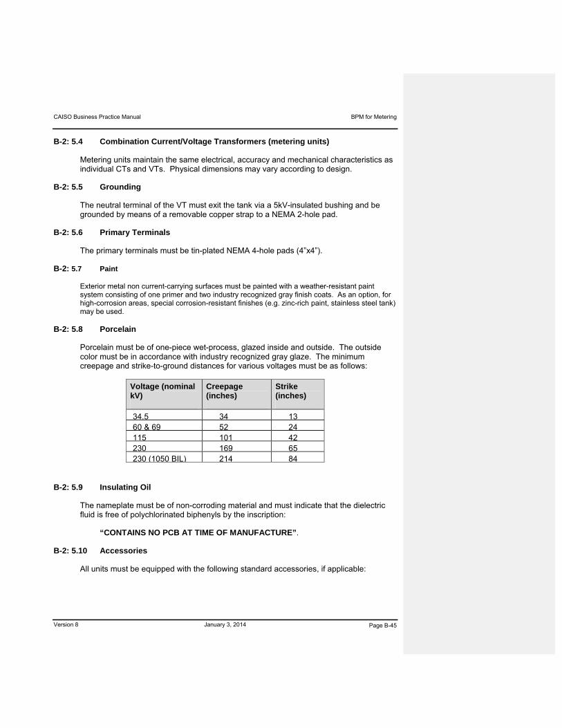
CAISO Business Practice Manual BPM for Metering
Version 8 January 3, 2014 Page B-45
B-2: 5.4 Combination Current/Voltage Transformers (metering units)
Metering units maintain the same electrical, accuracy and mechanical characteristics as individual CTs and VTs. Physical dimensions may vary according to design.
B-2: 5.5 Grounding
The neutral terminal of the VT must exit the tank via a 5kV-insulated bushing and be grounded by means of a removable copper strap to a NEMA 2-hole pad.
B-2: 5.6 Primary Terminals
The primary terminals must be tin-plated NEMA 4-hole pads (4”x4”).
B-2: 5.7 Paint
Exterior metal non current-carrying surfaces must be painted with a weather-resistant paint system consisting of one primer and two industry recognized gray finish coats. As an option, for high-corrosion areas, special corrosion-resistant finishes (e.g. zinc-rich paint, stainless steel tank) may be used.
B-2: 5.8 Porcelain
Porcelain must be of one-piece wet-process, glazed inside and outside. The outside color must be in accordance with industry recognized gray glaze. The minimum creepage and strike-to-ground distances for various voltages must be as follows:
Voltage (nominal kV)
Creepage (inches)
Strike (inches)
34.5 34 1360 & 69 52 24115 101 42230 169 65230 (1050 BIL) 214 84
B-2: 5.9 Insulating Oil
The nameplate must be of non-corroding material and must indicate that the dielectric fluid is free of polychlorinated biphenyls by the inscription:
“CONTAINS NO PCB AT TIME OF MANUFACTURE”.
B-2: 5.10 Accessories
All units must be equipped with the following standard accessories, if applicable:

CAISO Business Practice Manual BPM for Metering
Version 8 January 3, 2014 Page B-46
1/2” brass ball drain valve with plug
1” oil filling opening with nitrogen valve
Magnetic oil level gauge, readable from ground level
Primary bypass protector
Sliding CT shorting link
Four 7/8”x 2-3/8” mounting slots
Four 1” eyebolts on base for four-point lifting sling
1/4” threaded stud secondary terminals
Two conduit boxes, each with three 1-1/2” knockout
B-2: 6 Testing
The CAISO Metered Entity must ensure that, before shipment, each transformer is subjected to testing as prescribed by recognized industry standards and other tests including:
(a) Applied voltage test for primary and secondary winding withstand to ground;
(b) Induced voltage test for proper turn-to-turn insulation;
(c) Accuracy test for ratio correction factor and phase-angle verification to confirm 0.3% metering accuracy per recognized industry standards;
(d) Ratio test;
(e) Insulation Power Factor test;
(f) Polarity test;
(g) Leak test to assure integrity of gaskets and seals; and
(h) Partial Discharge Test may be done in conjunction with applied voltage testing to assure proper line-to-ground withstand.
The certified tests must be submitted to the CAISO.
B-2: 7 Required Information
The following drawings and information are required:

CAISO Business Practice Manual BPM for Metering
Version 8 January 3, 2014 Page B-47
(a) One set of drawings showing physical dimensions including mounting holes and primary CT terminal details, nameplate. The CAISO Metered Entity must ensure that it receives a schematic of connections from its supplier; and
(b) A copy of quality controls/quality assurance (QC/QA) manuals applicable to production of the transformer(s).
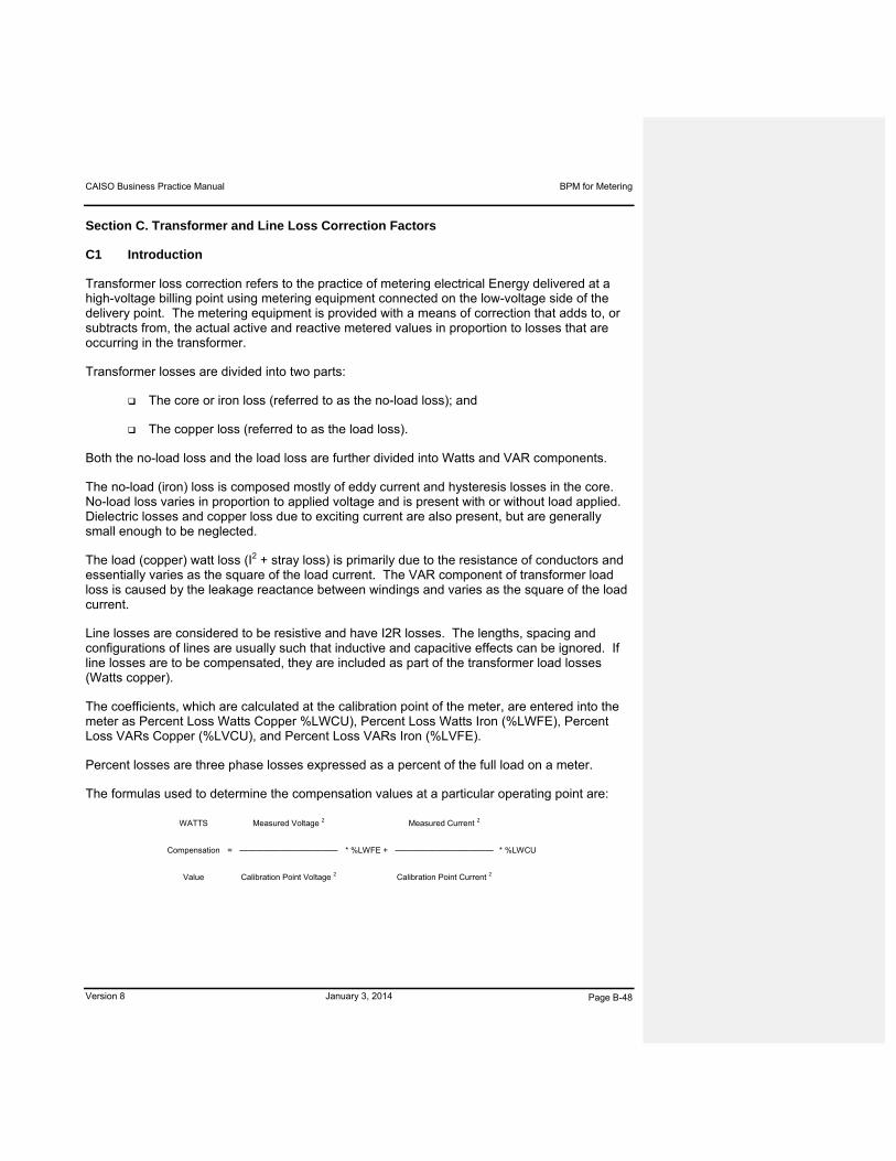
CAISO Business Practice Manual BPM for Metering
Version 8 January 3, 2014 Page B-48
Section C. Transformer and Line Loss Correction Factors
C1 Introduction
Transformer loss correction refers to the practice of metering electrical Energy delivered at a high-voltage billing point using metering equipment connected on the low-voltage side of the delivery point. The metering equipment is provided with a means of correction that adds to, or subtracts from, the actual active and reactive metered values in proportion to losses that are occurring in the transformer.
Transformer losses are divided into two parts:
The core or iron loss (referred to as the no-load loss); and
The copper loss (referred to as the load loss).
Both the no-load loss and the load loss are further divided into Watts and VAR components.
The no-load (iron) loss is composed mostly of eddy current and hysteresis losses in the core. No-load loss varies in proportion to applied voltage and is present with or without load applied. Dielectric losses and copper loss due to exciting current are also present, but are generally small enough to be neglected.
The load (copper) watt loss (I2 + stray loss) is primarily due to the resistance of conductors and essentially varies as the square of the load current. The VAR component of transformer load loss is caused by the leakage reactance between windings and varies as the square of the load current.
Line losses are considered to be resistive and have I2R losses. The lengths, spacing and configurations of lines are usually such that inductive and capacitive effects can be ignored. If line losses are to be compensated, they are included as part of the transformer load losses (Watts copper).
The coefficients, which are calculated at the calibration point of the meter, are entered into the meter as Percent Loss Watts Copper %LWCU), Percent Loss Watts Iron (%LWFE), Percent Loss VARs Copper (%LVCU), and Percent Loss VARs Iron (%LVFE).
Percent losses are three phase losses expressed as a percent of the full load on a meter.
The formulas used to determine the compensation values at a particular operating point are:
WATTS Measured Voltage 2 Measured Current 2
Compensation = ———————————— * %LWFE + ———————————— * %LWCU
Value Calibration Point Voltage 2 Calibration Point Current 2

CAISO Business Practice Manual BPM for Metering
Version 8 January 3, 2014 Page B-49
VARs Measured Voltage 4 Measured Current 2
Compensation = ———————————— * %LVFE + ———————————— * %LVCU
Value Calibration Point Voltage 4 Calibration Point Current 2
C2 Calculating Transformer Loss Constants
Transformer loss correction calculations with electronic meters are accomplished internally with firmware. Various setting information and test data is required to calculate the four values which are to be programmed into the meter.
The following information is required about meter installations:
The transformer high voltage (HV) voltage rating
The transformer kVa rating
The transformer high voltage (HV) tap settings
The transformer low voltage (LV) tap settings
The transformer connection (wye or delta)
The transformer phases (1 or 3)
The voltage transformer (VT) ratio
The current transformer (CT) ratio
The number of meter elements
The following data from a transformer test report is required:
No-load (iron) loss
Full-load (copper) loss
Percent impedance
Percent excitation current
The test data required may be obtained from the following sources:
The manufacturer’s test report
A test completed by a utility or independent electrical testing company
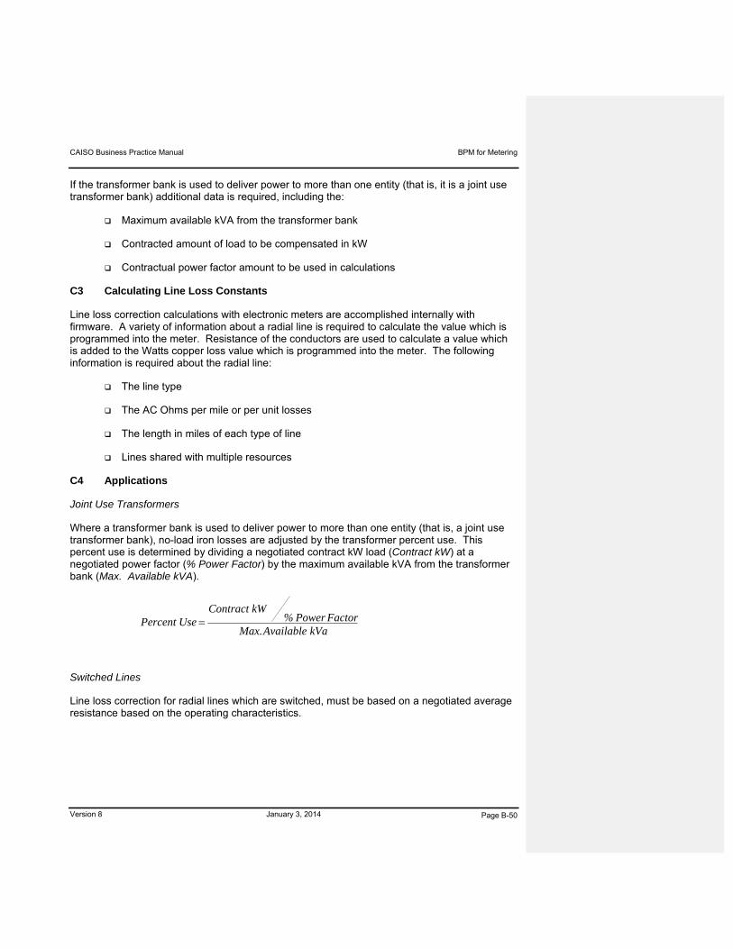
CAISO Business Practice Manual BPM for Metering
Version 8 January 3, 2014 Page B-50
If the transformer bank is used to deliver power to more than one entity (that is, it is a joint use transformer bank) additional data is required, including the:
Maximum available kVA from the transformer bank
Contracted amount of load to be compensated in kW
Contractual power factor amount to be used in calculations
C3 Calculating Line Loss Constants
Line loss correction calculations with electronic meters are accomplished internally with firmware. A variety of information about a radial line is required to calculate the value which is programmed into the meter. Resistance of the conductors are used to calculate a value which is added to the Watts copper loss value which is programmed into the meter. The following information is required about the radial line:
The line type
The AC Ohms per mile or per unit losses
The length in miles of each type of line
Lines shared with multiple resources
C4 Applications
Joint Use Transformers
Where a transformer bank is used to deliver power to more than one entity (that is, a joint use transformer bank), no-load iron losses are adjusted by the transformer percent use. This percent use is determined by dividing a negotiated contract kW load (Contract kW) at a negotiated power factor (% Power Factor) by the maximum available kVA from the transformer bank (Max. Available kVA).
kVa Available Max.Factor Power %
kW ContractUse Percent
Switched Lines
Line loss correction for radial lines which are switched, must be based on a negotiated average resistance based on the operating characteristics.

CAISO Business Practice Manual BPM for Metering
Version 8 January 3, 2014 Page B-51
Transformer Load Tap Changer
Transformers equipped with a load tap changer (i.e., which has the capability to change transformer voltage tap positions or settings under Load) for regulating voltage, must have the corrections calculated at the median tap voltage. Differences in the corrections must be minimal and must even out over time as the bank operates above and below the median tap voltage.

CAISO Business Practice Manual BPM for Metering
Version 8 January 3, 2014 Page B-52
Section D. Instrument Transformer Ratio and Cable Loss Correction Factors
D1 Background
All current transformers (CTs) and voltage transformers (VTs) (collectively, instrument transformers) have inherent errors due to their design and the physical properties of the materials used in their construction. These errors are manifested as a magnitude and phase angle difference between the “ideal” nameplate ratio and the waveform actually present on the secondary of the transformer. The terms used to denote these errors are Ratio Correction Factor (RCF) and Phase Angle Correction Factor (PACF).
The burden (load) connected to instrument transformer secondaries has an effect on the RCF and PACF of the units. All wiring and instrumentation of any kind is part of the burden. On a CT, the burden is designated in ohms and is represented by a number ranging from B-0.1 through B-1.8. On a VT, burden is measured in volt-amps and indicated by an alpha character, such as W, X, M, Y, Z or ZZ. The magnitude of these burdens must be known and kept within specified limits or additional errors occur in the metering.
Significant impedance in the leads between the VTs and the meter can be another source of error, where a voltage drop in the leads is caused by the load of the meter and any other connected devices between the VTs and the meter. Conductors which are too small or too long can cause metering error.
D2 Correction when the Burden Rating is exceeded
Where the connected burden of a metering circuit exceeds the burden rating of a CT or VT or if an existing instrument transformer does not meet minimum CAISO accuracy requirements, then one of the actions listed below must to be taken:
i. The preferred action is to correct the problem by either replacing the instrument transformer(s) with higher burden rated revenue class units or reducing the burden on the circuit to comply with the name plate of existing instrument transformer(s).
ii. An acceptable action is to apply CAISO approved correction factors to the meter to adjust the meter’s registration to compensate for inaccuracies.
The CAISO Metered Entity is responsible for properly calculating and applying the CT/VT and cable loss correction factors to its meter to adjust for inaccuracies in the metering circuit. CAISO approved algorithms and spreadsheets for calculating correction factors are included in this Part.
D3 CT Ratio Correction Factor
Current transformers are usually tested by the manufacturer for the value of RCF and phase angle at both 5 and 0.5 amp secondary currents. The values for each CT in an installation would be averaged together to determine the CT Ratio Correction Factor (RCFI) and CT Phase Angle (b). If the current transformers used are revenue metering with an accuracy class of 0.3
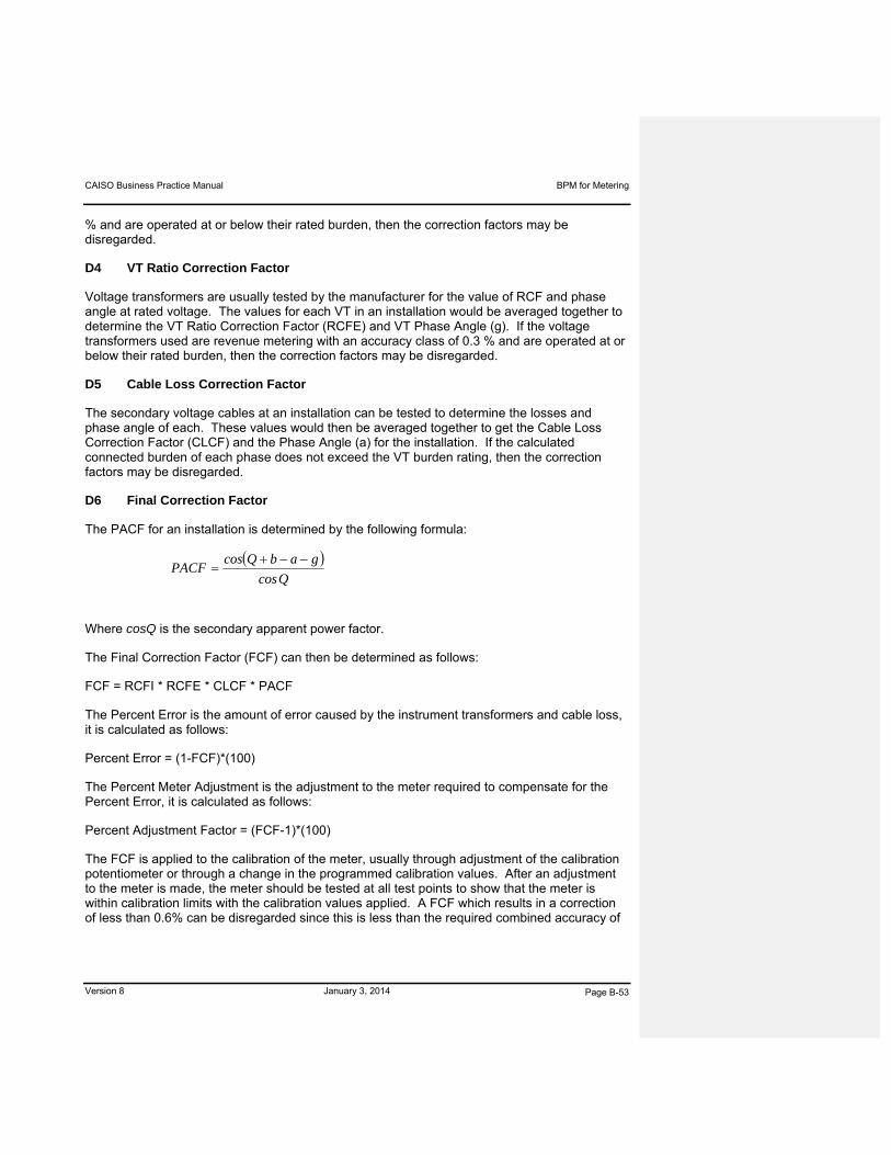
CAISO Business Practice Manual BPM for Metering
Version 8 January 3, 2014 Page B-53
% and are operated at or below their rated burden, then the correction factors may be disregarded.
D4 VT Ratio Correction Factor
Voltage transformers are usually tested by the manufacturer for the value of RCF and phase angle at rated voltage. The values for each VT in an installation would be averaged together to determine the VT Ratio Correction Factor (RCFE) and VT Phase Angle (g). If the voltage transformers used are revenue metering with an accuracy class of 0.3 % and are operated at or below their rated burden, then the correction factors may be disregarded.
D5 Cable Loss Correction Factor
The secondary voltage cables at an installation can be tested to determine the losses and phase angle of each. These values would then be averaged together to get the Cable Loss Correction Factor (CLCF) and the Phase Angle (a) for the installation. If the calculated connected burden of each phase does not exceed the VT burden rating, then the correction factors may be disregarded.
D6 Final Correction Factor
The PACF for an installation is determined by the following formula:
Qcos
gabQcosPACF
Where cosQ is the secondary apparent power factor.
The Final Correction Factor (FCF) can then be determined as follows:
FCF = RCFI * RCFE * CLCF * PACF
The Percent Error is the amount of error caused by the instrument transformers and cable loss, it is calculated as follows:
Percent Error = (1-FCF)*(100)
The Percent Meter Adjustment is the adjustment to the meter required to compensate for the Percent Error, it is calculated as follows:
Percent Adjustment Factor = (FCF-1)*(100)
The FCF is applied to the calibration of the meter, usually through adjustment of the calibration potentiometer or through a change in the programmed calibration values. After an adjustment to the meter is made, the meter should be tested at all test points to show that the meter is within calibration limits with the calibration values applied. A FCF which results in a correction of less than 0.6% can be disregarded since this is less than the required combined accuracy of

CAISO Business Practice Manual BPM for Metering
Version 8 January 3, 2014 Page B-54
the instrument transformers. However, if any correction factor (full load, light load or power factor) results in a correction of more than 0.6%, they should all be applied.
D7 Applications
Typical Installation
The preferred meter installation would utilize revenue metering class instrument transformers (0.3 %) operated at or below rated burden. If this is not the case, one or more of the following actions may be used to correct the problem:
Replace instrument transformers with higher burden rated units.
Reduce the burden on the circuit to comply with the existing rated burden.
Apply correction factors to the meter to compensate for inaccuracies.
Paralleling CTs
In normal revenue metering, current transformers would not be paralleled, but there are some applications where paralleling is done because the cost of the installation is reduced and the possibility of reduced meter accuracy is acceptable. A typical installation of this type would be to meter the net output of a generating station on a single meter rather than metering gross generator output and auxiliary power separately. In these type of installations additional rules apply:
All of the transformers must have the same nominal ratio regardless of the ratings of the circuits in which they are connected.
All transformers which have their secondaries paralleled must be connected in the same phase of the primary circuits.
The secondaries must be paralleled at the meter and not at the current transformers.
There should only be one ground on the secondaries of all transformers. This should be at their common point at the meter. Each utility may use their established grounding procedures.
Modern current transformers with low exciting currents and, therefore, little shunting effect when one or more current transformers are “floating” at no load should be used. Three or more “floating” current transformers might have an effect that should be investigated.
The secondary circuits must be so designed that the maximum possible burden on any transformer does not exceed its rating. The burden should be kept as low as possible as its effects are increased in direct proportion to the square of the total secondary current.
A common voltage and frequency must be available for the meter.
CAISO Business Practice Manual BPM for Metering
Version 8 January 3, 2014 Page B-55
If adjustments are made at the meter to compensate for ratio and phase angle errors, the ratio and phase angle error corrections used must represent the entire combination of transformers as a unit.
The watt-hour meter must be able to carry, without overload errors, the combined currents from all the transformers to which it is connected.
While servicing meters and equipment on parallel CT secondaries, all CTs must be by-passed (shorted). When work is completed all bypasses must be removed.
Section E. Distribution Compensation Factor (DCF)
E1 Overview
A Distribution Compensation Factor (DCF) is the term used in quantifying the effect a CAISO
Metered Entity generation has to the distribution facilities to which it is electrically connected to
and through which it must pass its registered energy delivery to the CAISO Point of Receipt
(POR).
E2 Determination of Distribution Compensation Factor (DCF)
The Distribution Compensation Factor must be based on an engineering study that is not in
conflict with any Tariff or Interconnection Agreements entered into between the CAISO Metered
Entity and the UDC/Distribution Provider for which they are an Interconnection Customer. The
engineering study must be an analysis of the effect the delivery of energy has on the distribution
system to which it is interconnected from the CAISO metered entities generator. The analysis
provides the accounting for any losses or credits attributed to delivery of the energy into that
distribution system at that point of interconnection.
The CAISO will recognize an engineering study found in or supporting a Distribution System interconnection agreement or Distribution System access tariff or agreement as a valid, independent study for purposes of determining the Distribution Compensation Factor.
In the absence of an engineering study, the CAISO will accept a default Distribution
Compensation Factor of 1.0.
E3 Application of Distribution Compensation Factor (DCF)
When a CAISO Metered Entity is connected to a Utility Distribution Company’s
(UDC)/Distribution Provider Distribution System, an approved Distribution Compensation Factor

CAISO Business Practice Manual BPM for Metering
Version 8 January 3, 2014 Page B-56
must be determined and must be programmed into the meter to reflect the point of delivery at
the CAISO Controlled Grid.
Agreement of the Distribution Compensation Factor by all parties will be a pre-condition to
CAISO meter certification.
E4 Engineering Study for Distribution Compensation Factor (DCF) Guideline
The Engineering study should provide the following:
Methodology of how DCF, loss or credit, was derived.
Detailed calculation on overall and system component losses.
Diagrams and power flows overall system including the point of interconnects.
Calculated sub-transmission energy loss multiplier and loss adjustments
Executive summary of the results including approved DCF.

CAISO Business Practice Manual BPM for Metering
Version 8 January 3, 2014 Page C-1
Attachment C
CAISO Authorized Inspector Initial Site Verification and Meter Test Procedures

CAISO Business Practice Manual BPM for Metering
Version 8 January 3, 2014 Page C-1
Attachment C: CAISO Authorized Inspector Initial Site Verification and Meter Test procedures
The intent of the site verification is to verify the metering circuit meets CAISO criteria prior to
issuance of a CAISO metering certification. The purpose of this site verification process is to
identify the duties of the person that will carry out the verification process for initial transformer
rated CAISO Metering sites. The person completing this procedure must have a working
knowledge of the instrument transformers, meters, local data server, and other associated
metering equipment as well as being knowledgeable of CAISO certification guidelines.
C1. Instrument Transformer Verification
In all cases, if the current transformers or voltage transformers (CT/VT) are not accessible
due to energized components or extensive disassembly is required that may impact plant
availability, the CAISO Authorized Inspector notes the unavailability and requests the owner
to identify a scheduled outage when the current transformer nameplate may be accessed
safely.
C1.1 Name Plate Accuracy (5)
The CAISO Authorized Inspector visually inspects the primary connections of the
current transformers and voltage transformers, then reads and records all the
current transformer and voltage transformer nameplate data on the Site
Verification Data Sheet. The nameplate data should include the following
information.
Manufacturer
Serial number
Voltage class
Type
Instrument Transformer ratios
Burden rating
Rating Factor
BIL

CAISO Business Practice Manual BPM for Metering
Version 8 January 3, 2014 Page C-2
ANSI Accuracy Class
The CT should comply with ANSI 0.3 Accuracy Class for metering current
transformers for B0.1 through B1.8 and the VT for X through ZZ. CAISO
approved correction factor algorithms are allowed to compensate for less than + -
0.3% accuracy.
C1.2 Phase and Polarity checks
CAISO Authorized Inspector verifies that the polarity mark on all CT/VT follow the
same convention. (i.e. all polarity marks connected using the same convention,) ,
with the H1 facing CAISO Grid. If there is more than one primary conductor
passing through the CT/VT, then the phasing must be verified.
C1.3 Ratio Check
CAISO Authorized Inspector verifies that the stated CT/VT ratio matches the
manufacturer’s nameplate ratio. Where it is determined that the ratio is greater
than + - 0.3% or ratio accuracy cannot be verified, a ratio test is required.
C1.4 Burden Check
The calculated or measured burden from all the equipment in the CT/VT circuit,
including the meter(s), should be less than the CT/VT burden designated on the
nameplate (reference ANSI Standard Burdens for instrument transformers).
C1.5 Transformer Correction Factor
If a transformer correction factor is applied to the meter, the CAISO Authorized
Inspector reviews the CT/VT data (ratio and phase angle test at the specified
burdens at full load) and the calculations (TCF7 at actual applied burden)
provided by the owner to verify the instrument transformers meet the 0.3
Accuracy Class requirements.
C2. Metering Service Verification
The purpose of the metering service verification is to verify the metering installation is wired
and operating properly.
7 Transformer Correction Factor

CAISO Business Practice Manual BPM for Metering
Version 8 January 3, 2014 Page C-3
The CAISO Authorized Inspector records the service information on the Site Verification
Sheet. The information includes the following:
Point of Receipt to the CAISO Controlled Grid and Service Voltage,
Power Transformer Rating
Type of Service (3W Delta, 4W Wye or single phase, etc).
C2.1 Recording at Meter Test Switch
CAISO Authorized Inspector reads and records the voltage and current at the meter
test switch. Record the date and time from the revenue meter. Isolate at the test
switch and remove the revenue meter. Install and program the solid-state test meter
for the appropriate service type.
C2.2 Recording Magnitude and Phase Angles
CAISO Authorized Inspector reads and records the magnitude and phase angles for
each of the phase voltages and currents at the meter test switch even if the meter is
not capable of producing angles.
C2.3 Required Method of Reading and Recording Voltage, Current and Phase Angles
C2.3.1 Preferred method for reading and recording voltage, current and all
phase angles is to utilize the diagnostic capability of the meter that displays the
necessary quantities.
C2.3.2 Read and record all current, voltage and phase angles readings on
the Site Verification Data sheet. Also, complete the vector diagram to indicate
the present phase relationships. Check for diagnostic errors.
C2.3.3 Check for diagnostic meter errors. If errors occur, analyze the site to
correct error. Indicate on the remarks section of the Site Verification Data
Sheet that a diagnostic meter error was detected.
C2.3.4 Complete the vector diagram with the recorded information. Compare
the vector diagram with the given unity vector diagram found on the borders of
the Site Verification Data sheet. Remember that the given vector diagrams are
at the unit power factor, so the site vector diagram are shifted by a given angle.
C2.4 Accuracy Test

CAISO Business Practice Manual BPM for Metering
Version 8 January 3, 2014 Page C-4
When possible, the meter accuracy testing must be performed when the unit is
offline. If the meter accuracy test is performed when the unit Is online it is prudent
that the CAISO Authorized Inspector monitor the generation output using other plant
instrumentation or have the plant operator maintain the generation at constant
output.
C2.5 Instantaneous Demand
CAISO Authorized Inspector compares the instantaneous demand from the test
meter to the instantaneous demand from the revenue meter and indicates the results
on the Site Verification Data Sheet
C3. Revenue Meter
Upon successful completion of the Instrument Transformer Verification and the Metering
Service Verification, the CAISO Authorized Inspector either performs or witnesses a test of
the Revenue meter. The recommended practice is to test the meter in place using a CAISO
approved watt-hour/var-hour standard and load box. The accuracy test should be
performed in the test mode to prevent the registration of test data in the meter. Before
taking the meter out of service, the CAISO Authorized Inspector verifies with CAISO Meter
Engineering that all clearances and permits are in effect. The CAISO Authorized Inspector
records the time the meter was taken out of service, the output level of the generator, if on-
line, and the time that the meter was placed back in service. All of the following information
is recorded on the Site Verification Data Sheet.
C3.1 Accuracy Test
CAISO Authorized Inspector either performs or witnesses the performance of
a calibration test on the revenue meter for watt-hour and var-hour function for
both directions of energy flow (delivered/received). Tests should be
performed with and without compensation applied to get a true test of the
metered site. Utilize a CAISO approved test set to perform the calibration
test.
C3.2 Transformer and Line Loss Compensation Settings & Instrument Transformer
Correction Factors
The Transformer and Line Loss Correction Factors compensation values, in
addition to the correction factors from the meter are compared to the values
found in the owner’s documentation for the specific location. If the values
CAISO Business Practice Manual BPM for Metering
Version 8 January 3, 2014 Page C-5
differ, the CAISO Authorized Inspector makes a note in the remarks section
of the Site Verification Data Sheet.
C3.2 Distribution Compensation Factors
The Distribution Compensation Factors compensation values are compared
to the values found in the owner’s documentation for the specific location and
those obtained by the CAISO. If the values differ, the CAISO Authorized
Inspector makes a note in the remarks section of the Site Verification Data
Sheet.
C3.3 Program and Input/Output Data check
The CAISO Authorized Inspector uses a laptop to verify correct programming
(program ID) and programming constants for the revenue meter. The CAISO
Authorized Inspector also verifies the proper operation of the KWh data
output with a volt-ohm meter, if the output is being utilized.
C4. Communications Circuit Test
The purpose of this test is to verify that the CAISO RMDAPS system can communicate with
the revenue meter. The communication circuit is typically either via a Frame Relay, ISDN,
56k digital circuit or switched phone circuit, etc.
CAISO Authorized Inspector requests the CAISO RMDAPS call the specific location and verify
that the meter communicates. If the communication has not been installed, the CAISO
Authorized Inspector uses a laptop or other test equipment to verify that the RS-232 ports of the
meters are operational. Simulate an event that is programmed into the meter (such as power
failure or threshold limit) and verify that the meter records and stores that event when polled by
CAISO RMDAPS.

CAISO Business Practice Manual BPM for Metering
Version 8 January 3, 2014 Page D-1
Attachment D
CAISO DATA VALIDATION, ESTIMATION AND
EDITING PROCEDURES FOR REVENUE
QUALITY METER DATA (RQMD)

CAISO Business Practice Manual BPM for Metering
Version 8 January 3, 2014 Page D-1
Attachment D: CAISO Data Validation, Estimation and Editing Procedures for Revenue Quality Meter Data (RQMD)
This attachment provides an overview of the process CAISO can utilize to VEE Meter Data
associated with CAISO Metered Entities (ISOME) and RMDAPS. The CAISO uses its best
judgment to select the validation routines used. Described below are the validations that are
available, as well as the current validations used by the CAISO. The CAISO will from time to
time review the validation routines being used to assure that VEE objectives are being achieved
and update this BPM identifying the currently used validations.
D1 Timing of Validation
Meter Data is remotely retrieved from CAISO Metered Entities by RMDAPS on a daily basis.
Validation is performed on the new Meter Data as it is retrieved from the meter in order to
detect:
Missing data
Data that could be invalid based upon status information returned from the meter
Meter hardware or communication failure
Additional validations can be performed on an as needed basis to verify data against Load
patterns, Backup Meters, Schedules, SQMDS load interval data and data obtained from
SCADA.
D2 Data Validation Conditions of Metering/Communications Hardware
RMDAPS detects the following conditions so that erroneous data is not used for Settlement or
billing purposes.
Validation detects the following metering/communication hardware failures:
Meter hardware/firmware failures
Communication errors
Data which is recorded during meter tests

CAISO Business Practice Manual BPM for Metering
Version 8 January 3, 2014 Page D-2
Mismatches between the meter configuration and host system master Master filesFile
Meter changeouts (including changing CT/VT ratios)
Gaps in data
Overflow of data within an interval
ROM/RAM errors reported by the meter
Alarms/phase errors reported by the meter
D3 Validation Criteria
Validation criteria are defined by CAISO for each channel of revenue quality interval data
(kW/kVAR/kVa/Volts, etc.) depending on the characteristics for each meter location and the type
of data being recorded.
Validation is based upon reasonable criteria that can detect both hardware and operational
problems with a high degree of confidence but is set so as to avoid unnecessary rejection of
data.
D4 Validation of Stated Criteria
Data validation is performed only for the validation criteria that have been entered for each
meter channel of data. For example, the number of intervals of zero Energy recorded by the
meter for the channel indicated is validated only when a non-zero value is entered for these
criteria.
Additional validation can be performed based upon usage patterns, comparisons to Backup
Meters, schedules or data obtained from SCADA.
D5 Validation Failure
Data that fails validation is flagged with the reason for the failure, where applicable. Data that
fails checks is identified so that manual intervention can be used to estimate the correct values
in order to edit the data or to manually accept the data.
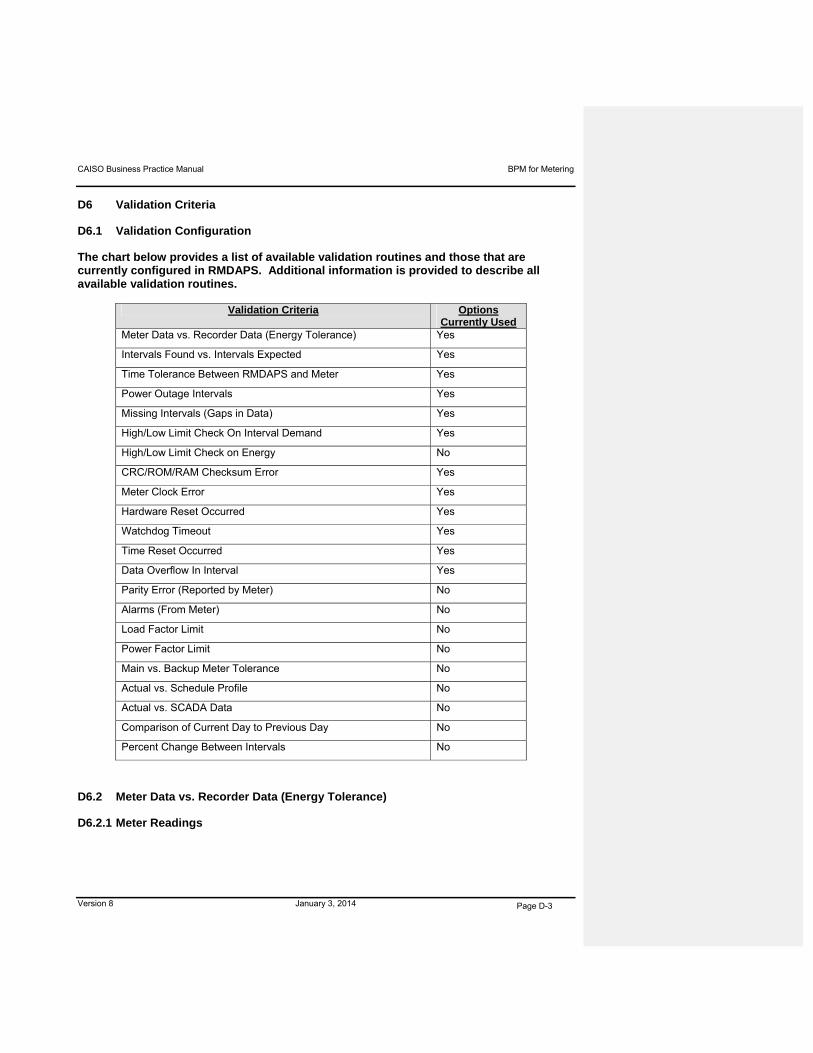
CAISO Business Practice Manual BPM for Metering
Version 8 January 3, 2014 Page D-3
D6 Validation Criteria
D6.1 Validation Configuration
The chart below provides a list of available validation routines and those that are currently configured in RMDAPS. Additional information is provided to describe all available validation routines.
Validation Criteria Options Currently Used
Meter Data vs. Recorder Data (Energy Tolerance) Yes
Intervals Found vs. Intervals Expected Yes
Time Tolerance Between RMDAPS and Meter Yes
Power Outage Intervals Yes
Missing Intervals (Gaps in Data) Yes
High/Low Limit Check On Interval Demand Yes
High/Low Limit Check on Energy No
CRC/ROM/RAM Checksum Error Yes
Meter Clock Error Yes
Hardware Reset Occurred Yes
Watchdog Timeout Yes
Time Reset Occurred Yes
Data Overflow In Interval Yes
Parity Error (Reported by Meter) No
Alarms (From Meter) No
Load Factor Limit No
Power Factor Limit No
Main vs. Backup Meter Tolerance No
Actual vs. Schedule Profile No
Actual vs. SCADA Data No
Comparison of Current Day to Previous Day No
Percent Change Between Intervals No
D6.2 Meter Data vs. Recorder Data (Energy Tolerance)
D6.2.1 Meter Readings

CAISO Business Practice Manual BPM for Metering
Version 8 January 3, 2014 Page D-4
Meter readings are obtained from CAISO approved meters on a daily basis in order to validate
interval Energy measurements. This Energy tolerance check is used to detect meter
changeouts or changes in metering CT/VT ratios that have not been reflected in the RMDAPS
master files (meter configuration files). A “tolerance type” parameter is set in the RMDAPS
system parameter to define the type of check to be performed.
The types of check that can be used include the following:
ID Term Description
M Multiplier Allows a percentage of the meter multiplier difference between the
meter reading the recorded interval total energy.
P Percent Allows a percentage of the metered total energy difference between
the metered total energy and the recorded total energy. The percent
of allowed difference is defined by CAISO on an individual meter
channel basis.
Q Same as
percent
Based on 30 days of data. If the data relates to a period less than 30
days then the total usage is projected to 30 days as follows:
Projected Usage=Total Usage*(30/Total Days)
D Dual
Check
Percent Method (P) is the primary check. If it fails, then the Multiplier
Method (M) is used.
E Dual
Method
Percent Method (Q) is the primary check. If it fails, then the Multiplier
Method (M) is used.
N None No tolerance check
D6.2.2 Intervals Found vs. Intervals Expected
RMDAPS calculates the expected number of time intervals between the start and stop time of
the data profile file and compare that number against the actual number of time intervals found
in the RMDAPS data file. The calculation used to determine the expected number of time
intervals takes into account the size or duration of the actual time intervals for the particular
meter/data file (e.g., 5 min, 15 min, 30 min and 60-min interval sizes).
D6.2.3 Time Tolerance between RMDAPS and Meter
When RMDAPS retrieves data from a meter, the RMDAPS workstation clock is compared
against the meter’s clock. RMDAPS is configured to automatically update the meter closes
within certain tolerances, limits and rules including:
A time tolerance parameter (in seconds) that indicates the allowable difference between
the RMDAPS workstation clock and the meter clock (if the meter clock is within that
parameter, RMDAPS does not update the meter clock)
CAISO Business Practice Manual BPM for Metering
Version 8 January 3, 2014 Page D-5
An upper limit for auto timeset that is the maximum number of minutes a meter can be
out of the time tolerance before RMDAPS performs an auto timeset
RMDAPS does not perform auto timesets across interval boundaries
The auto timeset feature supports DST changes and time zone differences. Since all
CAISO Metered Entity’s meters that are polled by RMDAPS are set to Standard Time,
this rule does not generally apply
D6.2.4 Number of Power Outage Intervals
CAISO approved meters record a time stamped event for each occurrence of a loss of AC
power and a restoration of AC power. During the Meter Data retrieval process, RMDAPS flags
each RMDAPS interval between occurrences of AC power loss and AC power restoration with a
power outage status bit.
D6.2.5 Missing Intervals (Gap in Data)
The RMDAPS validation process compares the stop and start times of two consecutive pulse
data files for a meter and reports if a missing interval/gap exists.
D6.2.6 High/Low Limit Check on Interval Demand and Energy
The RMDAPS validation process compares the Demand and Energy High/Low Limits entered
by the RMDAPS operator on a meter channel basis in the RMDAPS meter channel table
against the actual values collected from the meter. This comparison is performed on an
interval-by-interval basis. If the actual values are either less than the Low Limit or greater than
the High Limit, then the RMDAPS validation process fails.
D6.2.7 CRC/ROM/RAM Checksum Error
This general meter hardware error condition can occur during an internal status check or an
internal read/write function within the meter. This error code is not standard on some meters
(reference must be made to the meter’s user manual). When available, this internal status
information is collected during the RMDAPS Meter Data retrieval process and stored for
review/reporting purposes.
D6.2.8 Meter Clock Error
This meter hardware error condition can occur whenever an internal meter hardware clock error
results in an invalid time, day, month, year, etc. This error code is not standard on some meters
(reference must be made to the meter’s user manual). When available this interval status
CAISO Business Practice Manual BPM for Metering
Version 8 January 3, 2014 Page D-6
information is collected during the RMDAPS Meter Data retrieval process and stored for
review/reporting purposes.
D6.2.9 Hardware Reset Occurred
This meter hardware error condition occurs whenever an internal meter hardware reset occurs.
This error code is not standard on some meters (reference must be made to the meter’s user
manual). When available this interval status information is collected during the RMDAPS Meter
Data retrieval process and stored for review/reporting purposes.
D6.2.10 Watchdog Timeout
This error code is not standard on some meters (reference must be made to the meter’s user
manual). When available, this feature watches for meter inactivity, indicating a possible meter
failure.
D6.2.11 Time Reset Occurred
This is a meter error code that indicates that the meter time has been reset. See Time
Tolerance Between RMDAPS and Meter.
D6.2.12 Data Overflow in Interval
This error code occurs when the amount of data in an interval exceeds the memory capabilities
of the meter to store the data. This alerts RMDAPS that there is corrupt data for the interval.
D6.2.13 Parity Error (Reported by Meter)
Parity error is another indicator of corrupted data.
D6.2.14 Alarms (From Meter)
CAISO RMDAPS operator can utilize meter alarms to determine if the alarm condition creates
data integrity problems that need to be investigated.
D6.2.15 Load Factor Limit
The RMDAPS validation process can compare the daily Load Factor to the limit entered by the
RMDAPS operator. RMDAPS prompts the operator to investigate data integrity if the limit is out
of tolerance.

CAISO Business Practice Manual BPM for Metering
Version 8 January 3, 2014 Page D-7
D6.2.16 Power Factor Limit
The RMDAPS validation process can compare the actual Power Factor to the limit entered by
the RMDAPS operator. RMDAPS prompts the operator to investigate if the limit is out of
tolerance.
D6.2.17 Main vs. Backup Meter Tolerance
The main and check Backup Meters can be configured in RMDAPS to be compared on a
channel by channel basis to the Backup Meter ID, channel number, percent tolerance allowance
and the type of check. Interval or daily Meter Data is entered into the corresponding main meter
RMDAPS meter channel table record. This information remains constant unless:
A meter changeout occurs at the site
The percent tolerance allowance needs adjusting
The type of check is switched
If the percentage difference between the main channel interval Demand and the check channel
interval Demand exceeds the Percent Tolerance allowed, the RMDAPS validation fails. If, after
applying this validation test, the percentage difference between the main channel total Energy
and the check channel total Energy for each Trading Day exceeds the allowed percentage, the
RMDAPS validation fails. In both cases, if the percentage difference is less than the Percent
Tolerance allowed, the RMDAPS validation is accepted.
D6.2.18 Actual vs. Schedule Profile
Data can be compared on an interval by interval basis like main meter vs. Backup Meter.
D6.2.19 Actual vs. SCADA Data
Data can be compared on an interval by interval basis like main meter vs. Backup Meter.
D6.2.20 Comparison of Current Day To Previous Day
The RMDAPS validation process can compare the last complete days’ Demand and Energy in
the validation time period to one of the following parameters configured by the RMDAPS
operator:
Previous day
Same day last week
CAISO Business Practice Manual BPM for Metering
Version 8 January 3, 2014 Page D-8
Same day last month
Validation failure
If the percentage difference between the Demand and Energy exceeds the tolerance setup in
the RMDAPS validation parameters, the data subjected to the validation process fails.
D6.2.21 Percent Change Between Intervals
The RMDAPS validation process can utilize the Interval Percent Change Tolerance set by the
RMDAPS operator on a meter channel basis in the RMDAPS meter channel table to compare
the percentage change in the pulses for the channel between two consecutive intervals. If the
percent change exceeds the Interval Percent Change Tolerance set for that channel, the
RMDAPS validation process fails.
D7 Data Estimation Criteria
When interval data is missing due to there not being any response from the meter or the meter
reports it as missing, RMDAPS supplies estimated data for the missing intervals based on the
guidelines discussed below.
If a certified Backup Meter is available and that data is valid, the data from the Backup Meter is
used to replace the invalid or missing data from the main meter. When interrogating meters on
a frequency basis, the point-to-point linear interpolation method is used to estimate the current
interval(s) of data. This method is normally only used when estimating one hour or less of
contiguous missing interval data when the previous and next intervals are actual values from the
meter. If data is missing for an extended timer period, historical data, schedules, load profiles or
data obtained from SCADA can be utilized. Currently, the estimation process is performed
manually using the appropriate routine below, as determined by the RMDAPS operator, based
on the available information and the issue causing the need for estimation.
D7.1 Data Estimation Methods
The following data estimation methods are configurable by the RMDAPS operator on a meter-
by-meter basis. The algorithms for each method are described below in order of precedence as
implemented by the RMDAPS automatic estimation application software. The RMDAPS
operators can alter this order by simply not activating a certain method. In addition, the
RMDAPS operator can manually select each data estimation method at any time during the
data analysis process.

CAISO Business Practice Manual BPM for Metering
Version 8 January 3, 2014 Page D-9
D7.1.1 Main vs. Backup Meter
The global primary and Backup Meters can be configured in the RMDAPS meter channel table
to be compared on a channel-by-channel basis. The Backup Meter ID and channel number
must be entered into the corresponding primary meter RMDAPS meter channel table record.
This information remains constant unless a meter change out at the site occurs. During the
RMDAPS automatic estimation process, if missing data is encountered and actual values from a
certified Backup Meter are available, the values for the corresponding intervals from that
Backup Meter can be substituted into the data file for the primary meter. All copied intervals are
tagged as an edited interval. In order for actual values from the Backup Meter to be deemed
acceptable for use in the data file that passed the validation criteria preferred to earlier in this
attachment and no error codes or alarms can be set on the interval values. Meter Data from
Backup Meters is only used where Meter Data is not available from the primary meter and the
Backup Meter is an ISO certified meter.
D7.1.2 Point-to-Point Interpolation
When reading meters on a frequency basis, the Point-to-Point Linear Interpolation Algorithm
described below can be used to estimate the missing intervals of data. This method is normally
only used to estimate a maximum of one hour of contiguous missing interval data when the
previous and next intervals are actual values from the meter. Even though this method is not
normally used above that maximum of one hour, the RMDAPS allows this maximum threshold
to be set by the RMDAPS operator on a meter-by-meter basis. The same rules for defining
acceptable actual values apply as detailed in main vs. Backup Meter description above. All
estimated intervals are tagged as an edited interval.
Point-to-Point Linear Interpolation Algorithm
Estimated Interval = (Next Actual – Previous Actual Interval)/(Number of Missing
Intervals + 1) + Previous Actual Interval
D7.1.3 Historical Data Estimation
Historical data estimation is the process of replacing missing or corrupt interval data in the
RMDAPS data files. The data is replacing using historical data as a reference. There are two
basic requirements when estimating data to be inserted or replaced:
The amount of data to add or replace
The shape or contour of the data over the time span requested
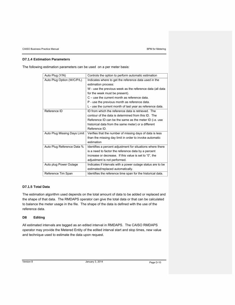
CAISO Business Practice Manual BPM for Metering
Version 8 January 3, 2014 Page D-10
D7.1.4 Estimation Parameters
The following estimation parameters can be used on a per meter basis:
Auto Plug (Y/N) Controls the option to perform automatic estimation
Auto Plug Option (W/C/P/L) Indicates where to get the reference data used in the
estimation process:
W - use the previous week as the reference data (all data
for the week must be present).
C – use the current month as reference data.
P - use the previous month as reference data.
L - use the current month of last year as reference data.
Reference ID ID from which the reference data is retrieved. The
contour of the data is determined from this ID. The
Reference ID can be the same as the meter ID (i.e. use
historical data from the same meter) or a different
Reference ID.
Auto Plug Missing Days Limit Verifies that the number of missing days of data is less
than the missing day limit in order to invoke automatic
estimation
Auto Plug Reference Data % Identifies a percent adjustment for situations where there
is a need to factor the reference data by a percent
increase or decrease. If this value is set to “0”, the
adjustment is not performed.
Auto plug Power Outage Indicates if intervals with a power outage status are to be
estimated/replaced automatically.
Reference Tim Span Identifies the reference time span for the historical data.
D7.1.5 Total Data
The estimation algorithm used depends on the total amount of data to be added or replaced and
the shape of that data. The RMDAPS operator can give the total data or that can be calculated
to balance the meter usage in the file. The shape of the data is defined with the use of the
reference data.
D8 Editing
All estimated intervals are tagged as an edited interval in RMDAPS. The CAISO RMDAPS
operator may provide the Metered Entity of the edited interval start and stop times, new value
and technique used to estimate the data upon request.

CAISO Business Practice Manual BPM for Metering
Version 8 January 3, 2014 Page D-11
If estimation and editing is frequently required for the Meter Data received from a particularly
metered entity, CAISO may require recertification and or facility maintenance or repair to correct
the continued provision of erroneous or missing data.
CAISO Business Practice Manual BPM for Metering
Version 8 January 3, 2014
Page E-1
Attachment E
CAISO AUDIT OF CERTIFIED METERING
FACILITIES

CAISO Business Practice Manual BPM for Metering
Version 8 January 3, 2014 Page E-1
Attachment E: CAISO Audit of Certified Metering Facilities
CAISO representatives audit Metering Facilities to ensure revenue data reliability. CAISO audit
of Metering Facilities is a SAS-708 Type II audit standard. Site audits involve mandatory visits to
CAISO Metered Entity sites. CAISO Metered Entity meters include all meters designated as
CAISO meters, regardless of their polled status.
1) CAISO requests a clearance to the Metering Facility in order to conduct a site
audit.
2) CAISO conducts the mandatory audit by comparing values and information
against data on file with the CAISO. CAISO Meter Engineer performs the
following:
a) Record and compare seal numbers with the last site inspection or audit.
Verify that CAISO approved seals are used where seals are required.
b) Compare the register constant, current and voltage ratios in the meter’s
program to ensure the integrity of the data
c) Verify the values that the meter uses to communicate the data to the CAISO
RMDAPS system
d) Verify the password on polled meters
e) Change the password on non-polled meters
f) Perform meter time correction if the meter’s time is off more than +- (1)
minute (time verification are made before a site visit and compared with the
United States Naval Observatory and updated on the Meter Engineer’s
laptop).
g) Conduct comparison of the load and or the generation to verify the display,
recorder files and the RMDAPS channel.
h) Affix a CAISO Revenue Metering audit sticker on all meters audited.
3) Meter Maintenance
8 Statement on Auditing Standards No. 70
CAISO Business Practice Manual BPM for Metering
Version 8 January 3, 2014 Page E-2
CAISO reports damaged meters, or meters requiring maintenance, and any other
meter-related problem found during an audit to the Metering Facility contact.
4) Meter Site Security
CAISO reports any revenue meter test switches or shorting switches for the
current circuit and the voltage circuit (if one exists) found unsealed. CAISO
ensures that the meter meets the meter site security requirements as detailed in
section 5.1.4 of this BPM.
5) Audit Results
CAISO completes an internal Metering Site Audit Form and updates the Metering
Facility file for each meter audited.
CAISO Business Practice Manual BPM for Metering
Attachment F
STATION POWER REALLOCATION EXAMPLE

CAISO Business Practice Manual BPM for Metering
Version 8 January 3, 2014 Page F-1
Attachment F: Station Power Reallocation Example
The following is an example assuming a Netting Period of 10 time periods with a Station Power
Portfolio including 3 sites all separated by CAISO Controlled Grid where each site has a Station
Power Load meter and an on-site generating facility. For a calendar month with 30 days, there
4,320 time periods for a unit in a Station Power Portfolio (6 ten-minute intervals per hour * 24
hours* 30 days)
1 2 3 4 5 6 7 8 9 10
(1) MonthlyNet
Generation
(2) Total Station Power Draws
(3) Rank for
Allocation
(4) Allocation of Third Party
Supply(5) Remote Self-Supply
Sum of Net Load
Ch 1 1.3 2.4 2.1 1.9 2.3 2.4 2.0 2.0 2.0 2.0Ch 4 34.0 0.0 0.0 0.0 0.0 0.0 0.0 0.0 0.0 0.0Net Load 0.0 2.4 2.1 1.9 2.3 2.4 2.0 2.0 2.0 2.0
Ch 1 1.0 2.0 3.0 2.0 2.0 3.0 3.0 2.0 2.0 3.0Ch 4 2.0 0.0 0.0 0.0 0.0 0.0 0.0 0.0 0.0 0.0Net Load 0.0 2.0 3.0 2.0 2.0 3.0 3.0 2.0 2.0 3.0
Ch 1 2.0 2.0 2.0 2.0 2.0 2.0 2.0 2.0 2.0 2.0Ch 4 0.0 0.0 0.0 0.0 0.0 0.0 0.0 0.0 0.0 0.0Net Load 2.0 2.0 2.0 2.0 2.0 2.0 2.0 2.0 2.0 2.0
Portfolio Total -27.4 63.4 27.4 13.6 61.1
(6) On-Site Self-Supply Load IDTime
Period 1 2 3 4 5 6 7 8 9 10 TotalSite 1 1.3 2.4 2.1 1.9 2.3 2.4 2.0 2.0 2.0 2.0 20.4 Meter Data AssumptionsSite 2 1.0 0.1 0.1 0.1 0.1 0.1 0.1 0.1 0.1 0.1 2.0Site 3 0.0 0.0 0.0 0.0 0.0 0.0 0.0 0.0 0.0 0.0 0.0
Total 22.4
(7) Third Party Supply Load IDTime
Period 1 2 3 4 5 6 7 8 9 10 Total
Site 1 0.0 0.0 0.0 0.0 0.0 0.0 0.0 0.0 0.0 0.0 0.0Site 2 0.0 1.9 2.9 1.9 1.9 2.9 2.9 1.9 1.9 2.9 21.0Site 3 0.6 0.6 0.6 0.6 0.6 0.6 0.6 0.6 0.6 0.6 6.4
Total 27.4
(8) Remote Self-Supply Load IDTime
Period 1 2 3 4 5 6 7 8 9 10 Total
Site 1 0.0 0.0 0.0 0.0 0.0 0.0 0.0 0.0 0.0 0.0 0.0Site 2 0.0 0.0 0.0 0.0 0.0 0.0 0.0 0.0 0.0 0.0 0.0Site 3 1.4 1.4 1.4 1.4 1.4 1.4 1.4 1.4 1.4 1.4 13.6
Total 13.6
0
0
13.6
19.1
22.0
20.0
23.0
20.0
21
0
6.4
"Netting Period" in this example is 10 Time Periods
Sites: Gen/Load
Time Period
METER DATA REALLOCATION PROCESSASSIGNMENT OF REMOTE SELF-SUPPLY AND THIRD PARTY SUPPLY
TO SITES AND TIME PERIODS
Site 1
Site 2
Site 3
NA
1
2
13.6
-21.0
-20.0
20.4
Notes:(1) Monthly Net Generation is Gross Generation less Gross Load over the Netting Period. If the value is positive for an individual site, then On-Site Self Supply is attributed to serving that site's Station Power load for the month. If the value for any individual site is negative, then Station Power load exceeded On-Site Self Supply in the Netting Period for each such site (i.e., a deficit in On-Site Self Supply existed). If the Total for the portfolio is positive, then Remote Self Supply is attributed to serving any deficits in On-Site Self Supply. To the extent that the Total for the portfolio is negative, then Third Party Supply has served Station Power in the portfolio.(2) The Station Power Draw is net Station Power load when a unit is off line, or generating less than its Station Power load. Total Station Power Draws represent the total Station Power Load excluding the Station Power that is netted under Permitted Netting. (3) When Third Party Supply is used, the magnitude of the Total Station Power Draws in the Netting Period is used to allocate Third Party Supply to each site. The site with the highest Total Station Power Draws will be allocated Third Party Supply until its negative Monthly Net Generation is fully served. If Third Party Supply remains to be allocated, then it is allocated to the site with the second highest Total Station Power Draws, and so on until the Third Party Supply is completely allocated.(4) The result of the assignment of Third Party Supply to each site as described in Note 3 is shown here.(5) Remote Self-Supply is attributed to serving any remaining Monthly Net Generation that is not assigned Third Party Supply as described in Note 3. (6) When Monthly Net Generation for an individual site is positive, then all of Station Power load is recorded onto the On-site Self-Supply Load ID for each period in the Netting Period. Zero load values should be recorded on that site's Remote Self-Supply and Third Party Self-Supply Load IDs.(7) The amount of Third Party Supply assigned to each site is distributed pro rata to the time periods in which each such site had a Station Power Draw. The assignment to each time period is: (Station Power Draw in that time period / Total Station Power Draws for that Site) X Allocation of Third Party Supply to that site. The site/time period allocation is to be used for rebating the cost of wholesale power. (8) Remote Self-Supply is assigned to each hour in the Netting Period as the difference between the Station Power load to be served and the amount of Third Party Supply assigned in that hour.

CAISO Business Practice Manual BPM for Metering
Version 8 January 3, 2014 Page F-1
Attachment G
Proxy Demand Resource (PDR) and Reliability
Demand Response Resource (RDRR)
Baseline Calculation Example

CAISO Business Practice Manual BPM for Metering
Version 8 January 3, 2014 Page F-1
Attachment G: PDR and RDRR Baseline Calculation Example
The following is an example of a Baseline, Load Point Adjustment, PDR Demand Response
Energy Measurement and Default Load Adjustment applicable for eitherboth a PDR or RDRR
Resource. (NOTE: the example does not include RT UIE adjustment as it is not applicable for
this DA award only example)
Baseline Calculation
Example: PDR Resource id PGEB_1_PDRC01 with following assumptions
DA awards for Trade Dates 4/26/09 and 4/27/09 HE14
DA award occurs in HE14 for TD 5/1/09
No other event hours for 5/1/09
Data used for calculating the Raw Baselinereh= (1 / ( d ) * ∑d Loadrdh
Default Load Adjustment is applicable
Formatted: Not Superscript/ Subscript

CAISO Business Practice Manual BPM for Metering
Version 8 January 3, 2014 Page F-1
Load Point Adjustment
The following is an example for the load point adjustment calculation:
Raw Baseline Metered Load
HE 10 13 12
HE 11 13 11
HE 12 13..4 12.5
SUM 39.4 35.5
Load Point Adjustment (Morning Adjustment) =
Max(.8, Min(1.2, sum load/sum raw baseline) =
Max(.8,min(1.2,35.5/39.4)) = .90

CAISO Business Practice Manual BPM for Metering
Version 8 January 3, 2014 Page F-1
PDR Energy Measurement
Example: PDR Resource id PGEB_1_PDRC01 (continued)
Assumptions:
DA award occurs in HE14 for TD 5/1/09
Real time adjustment not applicable since RT dispatch was not during the
event hour
No other event hours for 5/1/09
HE 14 SQMD submitted for PDR Registration 1 underlying load = 11.90
MWH
Load Point Adjustment = Morning Baseline Adjustment = .90
Default Load Adjustment (DLA) Example: PDR Resource id PGEB_1_PDRC01 (continued)
Assumptions:
Four PDR resources have event on TD 5/1/09 HE14
Therefore, a DLA is calculated for 3 separate LSE’s for PDR Generation in their DLAP


