Page 1
Grant Agreement No. 619572
COSIGN
Combining Optics and SDN In next Generation data centre Networks
Programme: Information and Communication Technologies
Funding scheme: Collaborative Project – Large-Scale Integrating Project
Deliverable D4.1
COSIGN Orchestrator Requirements and High Level Architecture
Due date of deliverable: December 2014
Actual submission date: January 16, 2015
Start date of project: January 1, 2014 Duration: 36 months
Lead contractor for this deliverable: IBM, Katherine Barabash
COSIGN
Project co-funded by the European Commission within the Seventh Framework Programme
Dissemination Level
PU Public X
PP Restricted to other programme participants (including the Commission Services)
RE Restricted to a group specified by the consortium (including the Commission Services)
CO Confidential, only for members of the consortium (including the Commission Services)
Page 2
619572 - ICT COSIGN [PUBLIC] D4.1
Combining Optics and SDN In next Generation data centre Networks
Page 2 of 53
Executive Summary
COSIGN [1] project’s goal is to create the blueprint of the future Data Centre network where highly
efficient optical interconnect technologies, controlled by the advanced programmable software control
plane, satisfy the diverse and dynamic requirements of modern Data Centre workloads.
COSIGN vision is that a unified orchestration layer is required to enable the Data Centre management
stack to efficiently manage the underlying resources while providing for the demands of multiple
heterogeneous workloads. WP4 of COSIGN is aiming at designing this orchestration layer based on
and as a part of the overall COSIGN architecture developed in WP1. In particular, the goal is to design
the orchestration layer and its interfaces to other COSIGN components as well as to exemplify it based
on the underlying optical data and control plane developed in WP2 and WP3, and on the projected use
cases and requirements outlined in D1.1.
This deliverable is the first milestone in the work on COSIGN orchestration layer with a goal to
review and to analyse the existing orchestrated DC/Cloud management solutions, and to outline the
high level architecture for COSIGN orchestrator. Major contributions of these work are: describe the
role of the orchestration layer in the overall Cloud Management Stack; analyse the orchestration layer
requirements based on the D1.1 output; present the platform choice alternatives based on the state of
the art study; outline the COSIGN orchestration layer architecture with its components, interfaces, and
workflows.
Page 3
619572 - ICT COSIGN [PUBLIC] D4.1
Combining Optics and SDN In next Generation data centre Networks
Page 3 of 53
Document Information
Status and Version: Final 2.0
Date of Issue: January 12, 2015
Dissemination level: Public
Author(s): Name Partner
Katherine Barabash IBM
Dean Lorenz IBM
Giada Landi NXW
José Ignacio Aznar i2CAT
Bingli Guo UnivBris
Shuping Peng UnivBris
Reza.Nejabati UnivBris
Dimitra Simeonidou UnivBris
Salvatore Spadaro UPC
Albert Pagès UPC
Fernando Agraz UPC
Alessandro.Predieri IRT
José Soler DTU
Cosmin Caba DTU
Edited by: Katherine Barabash IBM
Checked by : Sarah Renée Ruepp DTU
Page 4
619572 - ICT COSIGN [PUBLIC] D4.1
Combining Optics and SDN In next Generation data centre Networks
Page 4 of 53
Table of Contents
Executive Summary .............................................................................................................................. 2
Table of Contents .................................................................................................................................. 4
1 Introduction ..................................................................................................................................... 5
1.1 Reference Material ..................................................................................................................... 5 1.1.1 Reference Documents ....................................................................................................... 5 1.1.2 Acronyms and Abbreviations ........................................................................................... 5
1.2 Document History ...................................................................................................................... 6
2 Overview .......................................................................................................................................... 7
3 Orchestration Layer Requirements .............................................................................................. 8
3.1 The Role of the Orchestration Layer .......................................................................................... 8 3.1.1 Abstracting the Network Resources ................................................................................. 9 3.1.2 Abstracting the Demand ................................................................................................. 10
3.2 Orchestrator Requirements ....................................................................................................... 12 3.2.1 Virtual Data Centre ......................................................................................................... 12 3.2.2 Network Virtualization ................................................................................................... 13 3.2.3 Network Management .................................................................................................... 14
4 Orchestration Layer Architectures ............................................................................................. 16
4.1 State of the Art Survey ............................................................................................................. 16 4.1.1 Industrial Solutions and Products ................................................................................... 16 4.1.2 Academic Research ........................................................................................................ 28 4.1.3 Community Projects ....................................................................................................... 31
4.2 Reference Architecture ............................................................................................................. 35
5 COSIGN Orchestrator ................................................................................................................. 37
5.1 Architecture Outline ................................................................................................................. 37 5.1.1 Components .................................................................................................................... 37 5.1.2 Data Models and Interfaces ............................................................................................ 38
5.2 COSIGN Orchestrator for Virtual Data Centre ........................................................................ 39 5.2.1 Data Model ..................................................................................................................... 39 5.2.2 Workflows ...................................................................................................................... 41
5.3 COSIGN Orchestrator for Network Virtualization................................................................... 42 5.3.1 Data Model ..................................................................................................................... 42 5.3.2 Workflows ...................................................................................................................... 45
5.4 COSIGN Orchestrator for Network Resource Management .................................................... 46 5.4.1 Data Model ..................................................................................................................... 46 5.4.2 Workflows ...................................................................................................................... 48
6 Conclusions .................................................................................................................................... 51
Page 5
619572 - ICT COSIGN [PUBLIC] D4.1
Combining Optics and SDN In next Generation data centre Networks
Page 5 of 53
1 Introduction
1.1 Reference Material
1.1.1 Reference Documents
[1] COSIGN FP7 Collaborative Project Grant Agreement Annex I - "Description of Work"
[2] COSIGN FP7 D1.1 – "Requirements for Next Generation intra-Data Centre Networks Design". Link.
1.1.2 Acronyms and Abbreviations
Most frequently used acronyms in the Deliverable are listed below. Additional acronyms can be
specified and used throughout the text.
ACID Atomicity, Consistency, Isolation, Durability
AMPQ Advanced Message Queuing Protocol
API Application Programming Interface
AWS Amazon Web Services
BSS Business Support System
CFN Cloud Formation
CPU Central Processor Unit
DC Data Centre
DCN Data Centre Network
FW Firewall
GRE Generic Routing Encapsulation (tunneling protocol developed by Cisco)
GUI Graphical User Interface
GW Gateway
HOT Heat Orchestration Template
JSON Java Script Object Notation
KPI Key Performance Indicator
LAN Local Area Network
LB Load Balancer
MPLS Multiprotocol Label Switching
NAS Network Attached Storage
NAT Network Address Translation
NFV Network Function Virtualization
ONF Open Networking Foundation
OSS Operations Support System or Operational Support System
PHY Physical (as opposed to virtual)
QoS Quality of Service
RAM Random access Memory
REST REpresentational State Transfer
SAN Storage Area Network
SLA Service Level Agreement
SDN Software Defined Network
TOSCA Topology and Orchestration Specification for Cloud Applications (a cloud computing
standard of the OASIS information technology standards organization)
UML Unified Modeling Language
VDC Virtual Data Centre
VLAN Virtual Local Area network
VM Virtual Machine
Page 6
619572 - ICT COSIGN [PUBLIC] D4.1
Combining Optics and SDN In next Generation data centre Networks
Page 6 of 53
vNET Virtual Network
VPN Virtual Private Network
VxLAN Virtual Extensible LAN
WAN Wide Area Network
XML Extensible Markup Language
YAML YAML Ain't Markup Language (was Yet Another Markup Language)
1.2 Document History
Version Date Authors Comment
00 01/08/2014
See the list of
authors
Load initial ToC into the template
01 20/08/2014 Add executive summary and overview
02 27/08/2014 Amend ToC, add section description and tentative partner
assignments
03 30/09/2014 Rework following up DoW amendment – rename, add
IRT to the working group
04 30/10/2014 Finalize ToC, collect information references
05 04/12/2014 Incorporate first round of contributions (UPC, DTU, IBM)
06 08/12/2014 Add contents of section 3.2.2 (IBM)
07 12/12/2014 Add 3.2.1 (IRT)
08 15/12/2014 Complete the 4.2 and the 5.1 (IBM)
09 19/12/2014 Add 5.3 and 5.4 (DTU)
10 23/12/2014 5.2 and 5.3; clean up the references (IRT, IBM)
11 29/12/2014 Final contributions to section 4.1 (IBM), 5.2 (Bristol), 5.4
(UPC)
1.0 30/12/2014 Final editing, integration, conclusions
Page 7
619572 - ICT COSIGN [PUBLIC] D4.1
Combining Optics and SDN In next Generation data centre Networks
Page 7 of 53
2 Overview
This document is organized as follows.
Section 3 is devoted to specifying the orchestration layer requirements. First, the role of the
orchestration layer as part of the overall Data Centre Management Stack is described in Section 3.1.
Then, the requirements towards the orchestration layer are derived from the use cases identified as part
of WP1 deliverable [2].
Section 4 is devoted to the survey of the existing orchestration solutions for data centres and clouds,
and their interaction with the network management platform. We cover both the industrial and the
community solutions. In addition, we point to the specific open architectures that can be used as a
reference for building the COSIGN orchestrator.
Section 5 is devoted to the orchestration layer architecture proposed as part of the overall COSIGN
architecture. We first outline the generic architecture, specifying the components, presenting generic
data models, and showing the operational flows as part of the overall COSIGN architecture. Then we
briefly describe the specializations of the proposed architecture required to implement three major use
cases of COSIGN, namely: VDC, network virtualization, and network management.
Section 6 concludes the document by summarizing the architecture and providing the roadmap for
continuation of the WP4 work.
Page 8
619572 - ICT COSIGN [PUBLIC] D4.1
Combining Optics and SDN In next Generation data centre Networks
Page 8 of 53
3 Orchestration Layer Requirements
Next generation data centres, such as those of web-scale operators, cloud providers and large
enterprises, will have to satisfy very high demands, in terms of capacity, functionality, and reliability,
while ensuring profitability through optimizing the acquisition and the operational costs. These goals
are impossible to achieve either with the resource overprovisioning typical of today’s enterprise data
centres or with the resource oversubscription typical of today’s virtualized environments. Instead, next
generation data centres will have to right size the resource allocation continuously over time as the
demand and the conditions change. This is exactly the purpose of the data centre orchestration layer.
3.1 The Role of the Orchestration Layer
The role of the orchestration layer in the cloud management stack is to match the resource allocation
to the demand, continuously rebalancing the operational situation to satisfy global goals (e.g. client
SLAs or provider’s costs), by actively changing the configuration (e.g. of individual devices,
subsystems, or workload placement decisions). Ongoing assessment of the current functional and
performance status through monitoring and probing is essential to fulfil this important role.
It is important to note that the orchestrator makes DC-wide decisions, across resource silos (both
technological, and locational) and takes into account all the DC resources – compute, storage, and
networking, as shown in Figure 1 below.
Figure 1 The Role of the Orchestrator Layer is to coordinate resources across the siloes of Compute, Storage,
and Network, to the benefit of the deployed workloads and users
To fulfil its role the orchestrator consumes the services exposed by the infrastructure monitoring and
control functions of all the different resource types, in particular of the Data Centre Network (DCN).
In addition, the orchestrator extracts the demands from the upper layers, e.g. business logic or
workload automation tools. In order to effectively and efficiently match resources to demands, the
orchestrator has to create the right level of abstractions for both the resources and the demands. In this
section we describe these major requirements in detail, focusing on the networking part of the picture.
In particular, section 3.1.1 below deals with network resource abstraction towards the orchestrator, and
Page 9
619572 - ICT COSIGN [PUBLIC] D4.1
Combining Optics and SDN In next Generation data centre Networks
Page 9 of 53
section 3.1.2 deals with abstracting the demands from other entities such as Virtual Machine (VM)
placement, applications requests, etc.
3.1.1 Abstracting the Network Resources
The role of the orchestrator in the datacentre is to coordinate the underlying resources (e.g. compute,
network, etc.), out of which the network resources represent a significant part. The physical network
resources can be presented to the orchestrator as a pool of abstracted resources (e.g. network, switch,
port, tunnel, etc.). In this respect, the orchestrator application operates with the software abstractions
available in this pool of resources. These abstractions ensure that the orchestration layer is not tightly
coupled with the underlying DCN. Moreover, the abstraction of network resources creates a unified
view of the underlying heterogeneous network technologies (L0 - L4) across the DC.
The data models denoting the abstractions of network resources can be described using the Unified
Modeling Language (UML). Figure 2 shows an example of an UML diagram of a data model that
denotes an abstraction of a network resource. These data models may be uniformly represented
through hierarchies of software objects (i.e. three-like structures), which can be implemented in
several programming languages. In this context, each node (i.e. data/software object) in the hierarchy
would denote a virtual (abstracted) resource (e.g. tunnel, switch, etc.), which may be mapped to a set
of other virtual resources (children nodes), or to a physical resource (e.g. optical device). The
operations that the orchestrator performs on the abstract network resources would be applied to a set of
nodes (data objects) in the hierarchy. These operations might be further translated into commands that
are transmitted to devices in the physical network. For example, an operation for setting up a tunnel
means that several objects (e.g. switches) in the hierarchy of abstractions will change their state
accordingly. Furthermore, a set of commands may be sent to the corresponding physical devices, so
that the configuration is reflected in the physical network.
Figure 2 An UML description of a generic data model denoting the abstraction of a network resource
The abstraction of network resource may be performed at different levels, with different granularities.
The lowest level of abstractions would have a direct correspondent in the physical network. These
abstractions might, for example be:
1. Uniform Topology (abstractions for network elements): devices, links, and ports. The
abstraction may be divided into multiple layers, such as optical, L2 or L3 topological entities.
2. Monitoring (abstractions for statistics about the network and traffic): load, delay, packet
errors, packet drops, etc.
3. Quality of Service (QoS) Resources (abstractions for QoS resources): output queues, traffic
shapers, or other electrical or optical-related QoS resources. These abstractions enable
differentiation among different entities or sets of entities from the Uniform Topology, with the
purpose of serving applications’ requests with QoS awareness.
Page 10
619572 - ICT COSIGN [PUBLIC] D4.1
Combining Optics and SDN In next Generation data centre Networks
Page 10 of 53
4. Data Path (abstractions for paths through the optical DCN): these abstractions denote paths
established in the DCN. These may contain for instance tunnels (MPLS, VxLAN, GRE, etc.),
rack-to-rack optical paths (e.g. wavelength assignment), etc.
Higher level network abstractions can be realized based on the lower level abstraction described
previously. These abstractions might, for example be:
1. Network Slices: using the lower level abstractions defined previously; a slice comprises a set
of network resources. The resources may span multiple network layers (L0-L4) and may also
include QoS resources.
2. Service chain: a path in the network that traverses a set of specific nodes where the service
functions reside. Apart from the intermediate nodes, the path may be assigned a set of QoS
resources.
3. Network & Service Policies: abstractions for policies such as traffic isolation, security, access
lists, etc. These abstractions may rely on the topological information, data paths established in
the DCN, or other lower level abstractions.
The data centre orchestrator may directly operate with the network abstractions described previously.
It is also possible to create additional intermediate layers between the network abstractions and the
orchestrator. Such layers would implement more complex operations and services using the network
abstractions, and expose those services to the orchestrator. An example of such a service is overlay
networks that are customized according to customer or application policies.
The Open Networking Foundation (ONF) has a working group within the “Services” area, which
focuses on the description and standardization of northbound interfaces for network resources
abstractions [1]. Currently, the working group has released publicly only a charter document that
describes the targeted activities and the timeline for the deliverables.
3.1.2 Abstracting the Demand
Data centre orchestration layer is coordinating the underlying resource allocation to satisfy the demand
of the deployed applications and services. For this sake, it is important to understand the needs of each
application and service and to be informed of whether the needs are satisfied by the currently allocated
resources. From the networking perspective, this means understanding the connectivity requirements
of the workload as a whole, monitoring whether the requirements are satisfied by the currently
allocated resources, and deciding on best possible action to be taken if the change is required.
Note that resource re-allocation can be driven both by the workload side (e.g. change in application
demand, change in application components, adding new applications and services to the mix, etc.) and
by the infrastructure side (e.g. energy saving considerations can call for powering down parts of the
infrastructure when utilization is low). Note further that all types of the infrastructure – compute,
storage, and networking – have to be taken into account simultaneously, both as re-allocation drivers
and as targets of the re-allocation decisions. For example, if it is decided to power down some disks in
a storage server, DCN resources can have to be reassigned to provide less bandwidth to the part of
data centre where this storage server resides. Another example is that if DCN reports lack of resources
to provide required level of service to an application, it can be decided to migrate some of the
application components to another part of the data centre where application’s demands can be
satisfied.
From the connectivity perspective, applications can be seen as sets of communicating endpoints
defining whether endpoints inside and between the sets can communicate and, if yes, under what
conditions and with what quality of experience. Communicating endpoints can be of different types –
compute (virtual and physical servers), storage (NAS devices, SAN controllers, software defined
storage, etc), or network service appliances. Communication protocols, addressing schemes, and
traffic types are application dependent (e.g. different L3-L7 protocols), as well as the logical
topologies (e.g. multi-tier, clustered, client-server, etc.). Communication conditions, referred to as
policies, can also be of different types: allow or deny communications, subject communicated traffic
to filtering, rate limiting, or other in-transit services, and more. Quality of experience required by
Page 11
619572 - ICT COSIGN [PUBLIC] D4.1
Combining Optics and SDN In next Generation data centre Networks
Page 11 of 53
different applications can be specified as the upper limit of the allowed data transfer latencies,
survivable packet drop rates, and the required data transfer rates (bandwidth).
All the application connectivity aspects listed above have their representation in the networking layer
as forwarding paths, tunnels, routing rules, network appliance configuration settings, access limiting
rules on network ports, etc. Configuring the multitude of the infrastructure entities to satisfy an
application’s communication needs requires networking expertise and knowledge in the configuration
aspects of the specific devices currently deployed in the DCN. When an application’s requirements
change over time and when there is a need to simultaneously support a multitude of different
applications, the task becomes intangible for a human administrator and requires automation. In
addition to the sheer complexity of the task, semantic difficulty exists in mapping the application-
specified high level requirements towards the communication services and the infrastructure level
configuration changes required to satisfy the application’s demand. In traditional enterprise data
centres, resolving this difficulty requires highly skilled personnel, so that the application administrator,
partially knowledgeable in the infrastructure, talks to the infrastructure administrators, partially
knowledgeable in the application, figuring out the infrastructure layout, application component
placement, etc. This process is time consuming, error prone, and inefficient. Moreover, it is, again,
almost impossible to apply this process in a situation where multiple applications and multiple
application owners share the same underlying DCN infrastructure.
In next generation data centre application deployment is automated, application and infrastructure
administrators do not communicate and do not share domain knowledge. It is mandatory, therefore, to
extract application requirements towards the infrastructure, in particular to the DCN, in high level
terms. These terms, on the one hand, must faithfully reflect the application administrator’s intent
without involving the infrastructural constructs, while on the other hand, must be exactly translatable
to the infrastructure configuration settings.
Figure 3 A UML description of a generic data model denoting the abstraction of a data centre demand
Figure 3 presents a generic UML class diagram for abstracting the demand towards the DC resources.
Major model members are:
User – any entity that issues the demand, e,g. cloud tenant, DC operator, etc.
Workload – abstract entity representing the independent demand, e.g. application, DC slice or
VDC, service, etc.
Component – individually manageable workload element, e.g. database node, webserver,
forwarding or filtering service, etc.
Page 12
619572 - ICT COSIGN [PUBLIC] D4.1
Combining Optics and SDN In next Generation data centre Networks
Page 12 of 53
Policy – rule describing properties of the components and different conditions regarding their
multiplicity, sizing, communication channels, etc.
ResourceElement – entity of the infrastructure domain that is allocated to serve the workload,
connecting the demand abstraction model to the resource abstraction model.
3.2 Orchestrator Requirements
As described above, one of the requirements towards the data centre orchestrator is to formulate the
application-level demand in terms convenient to application administrators (developers and operators)
and in terms translatable to the infrastructure-level constructs. For different groups of workloads,
typical of different usage patterns, these demand formulations can be different. In this section, we
briefly describe three major groups of COSIGN use cases, focusing on application demand
specification they require. Figure 4 presents the Use Case UML diagram for the COSIGN
orchestrator, focusing on its major groups of use cases.
Actors shown on the right hand side of the figure are infrastructure-level actors COSIGN orchestrator
interacts with – the Network Manager, the Compute Manager, and the Storage Manager. The colour
code is used to signify that only the Network Manager is the agent developed as part of COSIGN
project, other infrastructural agents will be interacted through their existing interfaces. Still, it must be
noted that all the infrastructure-level actors participate in all the use cases of COSIGN.
Actors shown on the left hand side of the figure are user-level actors COSIGN orchestrator interacts
with – the DC Operator that activates the Manage DC use case (the Network Management), the VDC
Operator that activates the Manage VDC use case, and the Application Operator that activates the
Manage Application use case (the Virtual Networking use case of COSIGN).
Figure 4 A UML description of a generic use case model for the COSIGN orchestrator
3.2.1 Virtual Data Centre
Virtual Data Centre (VDC) is a concept of scalable, fully automated Infrastructure as a Service (IaaS)
solution to couple computing and storage infrastructure on demand with network connectivity among
the different components. The VDC service is typically designed to enable the user to design,
provision and manage cloud resources from a VDC Zone (e.g. physical data centre) and manage in a
fully automated way the deployment of Compute, Storage, Network and Security Appliances on-
demand, with elastic behaviours (i.e. scale-up/scale-down) to fulfil specific application requirements.
Orchestration of the different types of resources, as well as the control & optimization of the routing
and allocation of resources for the different users/tenants is a key function and enabler of any VDC
Page 13
619572 - ICT COSIGN [PUBLIC] D4.1
Combining Optics and SDN In next Generation data centre Networks
Page 13 of 53
service. In the following we briefly describe some of the VDC service functional elements and
highlight the specific requirements that impact the orchestration layer.
Typically a VDC service is managed through a Control Centre GUI that acts as customer self-service
portal.
Requirement. The VDC Control Centre needs to provide resource inventory and monitoring to
provide the VDC user and administrator with monitoring information for the resources
currently in use (resource status, events, alarms, etc.).
A VDC service needs to typically span across different Zones which generally correspond to
geographical regions and therefore go beyond the single Data Centre location (e.g. different VDC
Zones could correspond to different data centres located in different regions like Europe, North
America, Asia, etc.).
Requirement. The orchestration layer for the VDC use case has to keep a full visibility of the
available resources in the different Regions and Zones and be capable of allocating and
coordinating interconnection of them beyond the single DC.
Typically a VDC service consists of Computing (Virtual Machines), Storage and Network appliance
components allocated in the different zones.
Requirement. The orchestration layer has to provide templates for the different types of
resources that can be deployed and validate user’s requests against the available resources.
Requirement. The orchestration layer also needs to trigger control actions and proper
configurations on the resources to be allocated (e.g. to start/stop a VM, configure CPU/RAM,
network parameters or storage configurations, etc.).
Requirement. The orchestration layer should be capable of managing affinity groups for the
resources in order to ensure provisioning of virtual machines on independent hardware
resources, within one zone. This feature can increase the service availability in case of faults.
The VDC service is possible if a virtual network is created and controlled among the allocated virtual
resources.
Requirement. The orchestration layer must be capable of instantiating and configuring in a
coordinated way the virtual networks among VDC resources (including IP addresses, firewall
rules, egress and port forwarding rules, and load balancer configuration, etc.). In the specific
case of COSIGN DCN, the orchestrator must be able to trigger the proper configuration
actions via the SDN controller layer to instantiate the specific data paths across the COSGIN
optical data plane nodes.
3.2.2 Network Virtualization
The network virtualization use case relates to the multi-tenant (cloud) environment where multiple
applications owned and operated by multiple agents are simultaneously deployed in the common
shared data centre infrastructure. In such environments, it is both impractical and undesirable to
provide clients (application developers, operators, and users) with the physical infrastructure access
(visibility and control). Instead, virtualization of the infrastructural aspects (storage, compute, and
network) is mandatory in such environments to ensure proper isolation and sharing.
The orchestrator’s task in the network virtualization use case is to coordinate physical resource
allocation to meet the workload demand across the storage, the compute, and the network. Specifically
in COSIGN, we focus on network resource management as part of scenarios requiring coordination
between the storage, the compute, and the networking allocations. Such scenarios involve on-demand
bandwidth provisioning to a set of use-cases, such as: back-up or storage replication processes;
compute instance migration as part of disaster recovery and avoidance schemes; loading the image of
the compute instance to its physical host, etc. Additional group of scenarios is related to Network
Function Virtualization (NFV), where instances of network appliances have to be efficiently
provisioned and managed to satisfy the policies and the constraints.
Page 14
619572 - ICT COSIGN [PUBLIC] D4.1
Combining Optics and SDN In next Generation data centre Networks
Page 14 of 53
In order to fulfil its role in the network virtualization use case, the orchestrator has to receive and
interpret application level requests for the ICT resources. The requests can come in a form of
application blue-print (in modelling language such as TOSCA), or in a form of application-level or
infrastructure-level policy to be realized and maintained (e.g. disallow all communications with
version Y of protocol X or ensure all inter-rack traffic is encrypted).
Requirement. The orchestration layer should be capable of receiving the application level or
infrastructure level requirements towards resources from data centre users or administrators.
Requirement. Upon receiving the requirements, the orchestration layer should be able to
interpret them and make decisions as to what recourses should be allocated to satisfy the
requests.
Requirement. The orchestrator should be able to instantiate the decided resource allocation
scheme through interaction with the infrastructural layers, namely, the storage management,
the compute management, and the network management.
In modern data centres, the load is highly variable and high volume so that automatic realignment of
resource allocation decision is required periodically. To make such decisions, it is required to collect
the application performance data, on the one hand, and the resource utilization data on the other.
Resources utilization monitoring can be realized through infrastructure management layers, while
feedback regarding the application level KPIs can be hard to achieve in the generic case. In cases of
the special types of workloads, like storage or NFVs owned by the DC provider, the application
performance feedback loop can be implemented to exemplify the benefits. Such data is also required
to manage user SLAs and billing processes.
Requirement. The orchestrator should be able to continuously monitor resource utilization, for
storage, compute, and network, and to be capable of attributing the utilized resources to
applications/tenants.
Requirement. The orchestrator should provide the monitoring data to OSS/BSS tools for
billing and SLA monitoring.
Requirement. The orchestrator should provide a way for applications to report their perceived
KPIs or to monitor application level KPIs based on application requests (for example provided
as part of application blue-print).
Requirement. The orchestrator should continuously analyse the resource utilization and
application performance data to adjust the resource allocation decisions, across the storage, the
compute, and the networking domain.
3.2.3 Network Management
The network management use case refers to all the tasks involved in the DCN operations. The IT
services (such as computation and storage) offered by data centre infrastructure providers are
supported over a communication network (i.e., DCN) that needs to be operated properly. Hence,
although not being the final purpose of the provider, effective network management becomes crucial
for the business development in the data centre. Therefore, this use case is meant to co-exist with the
business related use cases previously described.
The tools typically associated to the DCN operation comprise inventory, monitoring and configuration
of the equipment. In addition to this single device management, it is also important for operators to be
aware about the DCN resource utilization and, as a consequence, about the resource availability. In
other words, operators need to know what resources are associated to what deployed client services
and what resources can be used to provide new ones. In the same line, resource optimization
capabilities are important to improve the infrastructure utilization and, thus, increase the business
incomes. Hence, to deploy this uses case, the set of tools that implements these functionalities has to
be incorporated to the orchestration layer.
In light of the above, the specific requirements that the orchestrator has to fulfil to implement the
network management use case can be summarized as follows:
Page 15
619572 - ICT COSIGN [PUBLIC] D4.1
Combining Optics and SDN In next Generation data centre Networks
Page 15 of 53
Requirement. Management, configuration and monitoring of network elements.
Requirement. Provisioning, maintenance and management of quality-assured (bandwidth,
latency, protection …) connectivity services (paths and circuits) that will support client
business workloads.
Requirement. Provide tenants’ self-management of the network services related to their own
workloads.
Requirement. Reception and processing of workload requirement-aware service requests. Such
requests will specify network related requirements (i.e., bandwidth, latency, etc.), which may
also change during the workload life cycle, and will be applied to the DCN by means of the
appropriated management and control tools.
Further reference on the requirements for this use case can be found in [2].
Page 16
619572 - ICT COSIGN [PUBLIC] D4.1
Combining Optics and SDN In next Generation data centre Networks
Page 16 of 53
4 Orchestration Layer Architectures
4.1 State of the Art Survey
In this section we survey the orchestration layer architectures offered as part of commercial products
(Section 4.1.1), proposed by the academic community (Section 4.1.2), and contributed as part of open
initiatives (Section 4.1.3). Existing known architectures are design to serve for different, often narrow,
use cases and there is currently no complete solution capable to integrate management of all the
infrastructural domains seamlessly. COSIGN DCN architecture, based on optical interconnect
technologies in the data plane and on the SDN principles in the control plane, poses unique
requirements towards the management and the orchestration layers. The purpose of the following
survey is to present the lively landscape of the developments in the DC orchestration area, to
understand the most useful use cases, and to guide the development of the COSIGN orchestrator.
4.1.1 Industrial Solutions and Products
Commercial cloud providers integrate several orchestration features into their service. Below, we
focus on the following features:
Auto-scaling: the orchestrator creates and terminates nodes automatically to meet optimization goals.
The orchestrator automatically triggers auto-scaling actions in response to various user-defined and
monitoring-based alarms.
Instance life-cycle management: the orchestrator creates instances from templates and supports life-
cycle management on these templates and the corresponding instances (e.g., supports rolling updates
of running instances upon template modification).
Service composition: the orchestrator can deploy a complex service composed of multiple instances
that can be of different types. The various components (compute, network, storage, external services)
are abstracted in a template that is used as a blueprint during service automatic deployment.
Network orchestration: the orchestrator automatically configures the network properties of each
instance and inter-connects them. The connectivity requirements are either specified in the service
composition template or implied by the deployment location (e.g., availability zones).
4.1.1.1 Amdocs Service Orchestrator
The Amdocs Virtualized Control Plane technology enables service providers to achieve faster time to
market for new services with higher elasticity for performance and scalability. The virtualized
environment is characterized by distributed software architecture, self-contained application clusters
with no scale limitations and independence from centralized session/state storage. The virtualized
Amdocs Policy Controller is a carrier-grade policy management solution that is supported by an
orchestration-neutral element manager.
The Amdocs Network Cloud Service Orchestrator is an open, vendor-agnostic orchestrator that can
manage VNFs from multiple vendors, using an abstracted workflow engine with per-vendor adaptors.
It employs a catalogue-driven solution to deploy network elements and reusable building blocks. It
uses continuous comparison of desired state, actual state, and new requirements to provide services at
SLA across physical and virtual functions.
Amdocs also provides guidelines for NFV requirements.
Horizontal scaling – NFV applications should be able to scale in or out based on traffic, in order to
avoid costly over-provisioning. The basic building block for auto-scaling is the ability to clone a
function and duplicate it. The clone has to contain all the configurations for that VNF to work as
expected in the network. Another building block is the ability to dynamically modify the
configuration and capacity of a VNF. Finally, there should be a mechanism to allow quick
deployment of several VNFs using a multi-application template.
Page 17
619572 - ICT COSIGN [PUBLIC] D4.1
Combining Optics and SDN In next Generation data centre Networks
Page 17 of 53
Vertical scaling – scale up or down through adding or removing resources (such as CPU, memory,
and IO) from VNF appliances. Another form of vertical scaling is replacing an existing VM with a
more powerful one; this can be done by adding the new VM to a cluster and removing the old one
(similar mechanisms to horizontal scaling). According to Amdocs, vertical scaling can also be in
the form of adding instances to existing VMs; while this does not increase overall capacity, it is
more fault tolerant.
Support different Hypervisors – allow selection of the best HV for each VNF and the utilization of
multi-vendor environments.
Interoperability – the VNF managers should support their own orchestration to allow deployment in
mixed vendor echo-systems. The NVF orchestration should be able to interact with all these
managers, including 3rd
party applications; thus, the orchestrator may use abstracted resources (or
even business goals), while the NVF managers translate these into concrete requirements that are
specific to the VNF. The orchestrator should allow running VNFs on 3rd
party HW; in particular, it
should allow for proprietary dedicated optimized bare-metal HW in combination with virtual
appliances.
Multi-tenancy – the implementation should support multi-tenancy with control over each tenant. This
allows better utilization of each VNF and of HW, especially for small workloads.
Upgradability – allow adding new services and updating existing ones without disrupting existing
running services.
4.1.1.2 Amazon AWS
Auto-scaling is built into the Amazon EC2 offering. It can automatically adjust the capacity (i.e., the
number of Amazon EC2 instances) to maintain performance during demand spikes and to decrease
cost when traffic subsides. Auto-scaling also detects problematic or impaired nodes and automatically
generates new replacement instances. EC2 auto-scaling rules can be triggered through CloudWatch
alarms (e.g., CPU utilization), service queue length, or by a pre-configured schedule (e.g., based on
seasonal trends).
Figure 5 Auto-scaling lifecycle
Page 18
619572 - ICT COSIGN [PUBLIC] D4.1
Combining Optics and SDN In next Generation data centre Networks
Page 18 of 53
Auto-scaling is managed per auto-scaling groups that consist of homogeneous instances (multiple
auto-scaling groups are allowed). All instances of an auto-scaled group are created from the same
launch configuration, i.e., instantiated from the same VM image and deployed on an identical instance
type (virtual HW configuration). Incoming traffic is automatically load-balanced across the auto-
scaling group by the Elastic Load Balancing (ELB) service, which also monitors the health of each
instance to ensure only healthy nodes receive traffic. Network addresses and security credentials are
automatically assigned to each new instance, either in a pre-defined subnet or based on the availability
zone(s) of the group or based on the Virtual Private Cloud (VPC) settings.
The EC2 auto-scaling orchestrator creates new instances or terminates existing ones to maintain
desired overall capacity for the auto-scaling group. Several scaling policies can be combined, each
triggered by different events (e.g., both health and demand monitoring) or optimized for different
goals (e.g., maintain availability, meet SLA, or minimize cost). Health-oriented policies are enforced
by periodic status checks of each EC2 instance and of the entire system to determine if any existing
instances should be terminated and new instance must be launched instead. The EC2 orchestrator also
interacts with the load-balancer (if exists) to check for out-of-service notifications and to attach new
nodes.
Performance-oriented policies (See Figure 5) are enforced by monitoring EC2 CloudWatch metrics
(e.g., CPU utilization or number of messages in queue), an alarm is fired if a metric is not within its
desired bounds, and the number of instances is adjusted according the triggered policy. Since instance
creation or deletion may take time, there is a cool-down period, at which subsequent alarms are
suppressed until the auto-scaling action is complete. Policies are flexible; for example, when adding
instances, a scale-out policy can define an absolute or relative (%) increment or a target value; when
terminating instances, a scale-in policy can additionally define that those with oldest launch
configurations and with closest billing hour are selected first. Alarms are also flexible and cannot only
monitor different metrics, but can also perform various time-based aggregations (e.g., “average CPU
utilization is above 80% for at least 3 consecutive periods of 5 minutes”).
Figure 6 EC2 Scaling Policy
Figure 7 AWS CloudFormation
AWS CloudFormation (see Figure 7) supports creation and management of a collection of related
AWS resources, provisioning and updating them in an orderly and predictable fashion.
CloudFormation uses a template (an AWS orchestration blueprint) to generate, interconnect, and
configure a “stack” of AWS instances of multiple types. The text-based template (JSON formatted)
can be captured from an existing deployment, and supports version control and configuration
management. The template can be parameterized through properties, mappings, and logical names,
allowing for further configuration during instantiation. For example, CloudFormation automatically
converts logical names in the template into concrete instance names for each created stack, avoiding
Page 19
619572 - ICT COSIGN [PUBLIC] D4.1
Combining Optics and SDN In next Generation data centre Networks
Page 19 of 53
name collisions when multiple stacks are created from the same template. Updates can be
implemented in two styles, either in-place or blue-green; with in-place style, updates are applied to a
working stack, while with blue-green style, a new updated stack is deployed without touching the
working one.
4.1.1.3 BMC Software
BMC Cloud Lifecycle Management is a hybrid (public/private) cloud management. BMC Cloud
Lifecycle Management provides blueprint technology and a graphical service designer to automate the
design, management and governance of simple to complex, multi-tiered service offerings. It supports
dynamically auto-scaling of cloud resources up (or down) to meet demand. It supports different cloud
infrastructure options (different vendors) and manages the entire service lifecycle, from design to
request, provisioning, monitoring, and decommissioning. Service blueprints are used to deploy an
entire service and automated placement of resources is controlled through compliance rules and
technical requirements. It supports policy-driven auto-scaling of cloud resources based on user-defined
service performance requirements. BMC Cloud Lifecycle Management interacts with BMC Server
Automation, BMC Network Automation, and BMC Capacity Management to provide compute
resource, network resources, and capacity optimization, respectively. Network requirements are
described through the blueprint model that allows for configuration of VLANs, address spaces,
network segments (including VIPs), zones, pairs, etc. The model also supports definition of physical
and virtual switches, load-balancers and firewalls; the connectivity between those components; and
detailed network paths. Three levels of abstraction are available, Pods, Containers & Zones; Pods are a
physical chunk of the cloud environment, bounded by network equipment (routers, firewalls, load
balancers, etc.); Containers are segments of the pod used to isolate tenants and workloads based on
policy; Zones exist within the network containers, creating separate security zones for different parts
of a cloud service (e.g., the DMZ).
Figure 8 BMC Cloud Lifecycle Management Functional Architecture
BMC Cloud Operations Management collects and analyzes cloud service resource consumption,
performance, and availability data spanning private, public, and hybrid clouds. Full-stack cloud
monitoring provides real-time visibility into the performance of a cloud managed by multiple cloud
stacks (e.g., BMC Cloud Lifecycle Management, VMware vCloudDirector, Amazon Web Services,
etc.). Cloud capacity views provide information on both current and future capacity and potential
Page 20
619572 - ICT COSIGN [PUBLIC] D4.1
Combining Optics and SDN In next Generation data centre Networks
Page 20 of 53
saturation of cloud containers to enable proactive management of the cloud environment and effective
planning for future capacity requirements.
4.1.1.4 CA Technologies
CA Automation Suite for Clouds is a cloud service delivery and management platform that provides
automated self-service delivery of virtual and physical infrastructure and application services. CA
Automation Suite for Clouds includes a foundation platform and a reference architecture that is made
of integrated enterprise IT management and automation products, such as CA Service Catalogue and
CA Process Automation.
Auto-scaling is provided through the CA Server Automation components, which integrate and
automate provisioning processes, and allow you to monitor and manage data centre resources. CA
Server Automation is a policy-based product that monitors, reconfigures, and provisions physical and
virtual resources to meet the load demands. It can integrate with cloud technologies from many
different vendors.
Figure 9 CA Server Automation
In addition to the portfolio of IT automation software, CA AppLogic Cloud Platform offers the so
called “software defined data centre”, enabling customers to quickly build cloud computing
environments in just hours, including the features needed to operate and manage the cloud. CA
AppLogic Cloud Platform integrates the IaaS, PaaS, SaaS, and private cloud solutions and eliminates
the binding of software to hardware by using virtual appliances. The solution includes the drag and
drop UI for application composition that includes the networking aspect. Applications thus created and
deployed are then served by the underlying network which is continuously monitored to deliver the
required QoS level.
4.1.1.5 Citrix CloudPlatform
Citrix CloudPlatform is a platform-agnostic cloud orchestrator that is based on the Apache CloudStack
API (see Section 4.1.3.2 below) and can manage a variety of hypervisors and even bare-metal servers.
It is massively scalable, and can orchestrate tens of thousands of physical or virtual servers in multiple,
geographically distributed data-centres.
Advanced network features and availability zones are provided through a cloud-era data centre
topology. CloudPlatform uses VLANs, SDNs, and Layer 3 security groups to isolate traffic between
Page 21
619572 - ICT COSIGN [PUBLIC] D4.1
Combining Optics and SDN In next Generation data centre Networks
Page 21 of 53
servers and tenants (see Figure 10). The creation of private VLANs, particularly for n-tier
applications, is automated and allows per-tier access-control policies. CloudPlatform also manages the
physical network and can configure properties such as network speed, IP trunks, etc. Other network
services, such as DHCP, NAT, load-balancing, and FW, are provided via a virtual router.
Figure 10 Citrix CloudPlatfrom Availability Zones
Auto scaling is supported through integration with NetScaler (deployed as physical or virtual
appliance) which expands and contracts the cloud according to business demands. Anti-affinity rules
can be added to auto-scaling policies to ensure that virtual instances of the same application (tier) are
deployed across multiple physical hosts. Auto-scaling policies define load-balancing rules (such as
stickiness) as well as scale-up and scale-down triggers. All new instances for a group are deployed
from the same template. NetScaler handles the monitoring both at service level (via SNMP) and at the
VM level and triggers scale-up actions on CloudPlatform to create new instances; it then discovers the
IPs of these instances, binds them to the service, and starts load balancing traffic to them. Scale-down
actions are handled similarly; NetScaler decides when to trigger the event based on monitoring; it then
selects a VM for termination and sops traffic to that VM; finally, it calls CloudPlatfrom to destroy the
VM.
Figure 11 Citrix CloudPlatfrom Autoscale Architecture
Page 22
619572 - ICT COSIGN [PUBLIC] D4.1
Combining Optics and SDN In next Generation data centre Networks
Page 22 of 53
4.1.1.6 Dimension Data
Dimension Data employs a network-centric cloud approach, focusing on automated, self-service
provisioning of actual networks in the cloud. It enables users to setup cloud networks similarly to
setting up cloud servers. The network elements, such as VLANs, firewalls and load balancers are
deployed on network infrastructure HW (e.g., on a Cisco switch), rather than being host-based. After a
network is deployed (using a REST-based API), cloud-servers can be assigned to it. Load-balancing
and resiliency is provided through utilization of more “traditional” tools, such as VIPs.
Dimension Data Cloud control provides automation of the orchestration, administration, provisioning,
management, support, metering and billing of cloud-based resources, both physical and virtual. It
enables federation between Public and Private Clouds to support hybrid scenarios, such as spill-over.
4.1.1.7 Flexiant Cloud Orchestrator
Flexiant Cloud Orchestrator Bento Box solution supports “cloud application blueprints”; these contain
all the key information and ‘bill of materials’ to build and deploy applications in the cloud, including
server, software, storage, network, images and firewall details, and most importantly how they all
relate together. Bento Box provides a graphical UI for blueprint composition and customizable
(parameterized) templates. Flexiant provides a library of blueprint from 3rd
party service providers to
enable selling and deployment of complex service stacks that require domain-specific know-how.
4.1.1.8 Google Cloud Platform
Google Compute Engine (GCE) includes several orchestration features, including auto-scaling, load-
balancing, resource management, and life-cycle management of virtual machine templates. The
Compute Engine Autoscaler automatically adds or removes resources to handle varying service loads.
The scaling is managed for a group of machines and is rule-based. Scaling rules model traffic load
based on CPU utilization (target level), serving capacity (% of maximum), or any other per-VM
monitoring metric. Managed groups consist of virtual machines and are assumed to be homogeneous
(i.e., all machines are instantiated from the same template).
The Load-Balancing service automatically balances requests across all instances of a group. As well as
load, the load-balancer monitors the health of virtual machines and can be configured to take into
account additional information, such as routing distances (e.g., for cross-region load-balancing),
forwarding rules, and content-based routing.
Figure 12 GCE network load balancing
Page 23
619572 - ICT COSIGN [PUBLIC] D4.1
Combining Optics and SDN In next Generation data centre Networks
Page 23 of 53
Figure 13 GCE load balancing cross region
Figure 14 GCE content load balancing
The Instance Group Updater can be used to apply a rolling update of a new template to all existing
instances. The speed of a rolling update can be fully controlled, it can be paused and even rolled-back.
Rolling updates are coordinated with auto-scaling, so a new template is used for a new auto-scaled one
only if the update has progressed enough.
Orchestration of networking resources consists of automatic network configuration (e.g., the default
gateway) for each new instance. There is no abstraction of network elements and the network cannot
be configured directly; for example, the capacity of the network cannot be set; instead, there is a fixed
i/o capacity (network and storage) allocated per each compute core (i.e., the overall capacity at any
point in time is determined by the number of cores deployed). Policy is abstracted through the ability
to create route collections for outgoing traffic and chains of simple firewall rules for incoming traffic.
The route collection pool is used by each instance to generate an individual routing table for its
outgoing traffic. These routes can be used to orchestrate more advanced network configurations (e.g.,
VPNs, transparent proxies, NAT, etc.). Storage, like networking, is not managed directly, but rather
allocated per compute node. Storage is mainly used through managed storage services, which have
independent auto-scaling and orchestration mechanisms.
4.1.1.9 HP Helion OpenStack® Orchestration Service
The HP Helion OpenStack Orchestration service leverages OpenStack Heat (see Section 4.1.3.1
below) to provide template-based orchestration for describing a cloud application. It executes
OpenStack API calls to generate running cloud applications on the HP Helion OpenStack cloud, a
commercial distribution of the open source OpenStack platform. It also supports scale-out and scale-in
on OpenStack cloud itself, namely, add and remove Hypervisor nodes (as opposed to scaling only the
VMs).
Page 24
619572 - ICT COSIGN [PUBLIC] D4.1
Combining Optics and SDN In next Generation data centre Networks
Page 24 of 53
Figure 15 HP Operations Orchestration Flow Example
HP Helion OpenStack Networking is a virtual networking service that leverages the OpenStack
Neutron service to provide network connectivity and addressing to HP Helion OpenStack Compute
service devices. The Networking service also provides an API to configure and manage a variety of
network services and configure virtual network topologies. It also provides Distributed Virtual
Routing (DVR) which provides connectivity among different Virtual Network Switches (VNSs) as
well as connectivity between VNS hosts and the external network. Distributed Virtual Routing is
achieved through per-tenant distributed virtual routers, allowing per-tenant to connectivity policies. A
distributed virtual router is conceptually a single entity, but it is implemented across all the OpenFlow
switches in the network. There is no single routing instance running on a single machine/hypervisor
that all the VNS traffic must route through. In addition to this, there is a system-wide distributed
virtual router which connects different tenant routers and defines the connectivity among different
tenants and to the outside world.
HP Operations Orchestration provides automated end-to-end service provisioning for multiple cloud
platforms, including both virtual and bare-metal deployments. It uses workflows to describe virtual
components, their connectivity and deployment order. There is life-cycle management for the
workflow, including authoring, content library, versioning, debugging, etc. Each flow is made of
Operations, Inputs, Responses, and Transitions; each Operation step uses Inputs to perform a task,
from which it obtains results as a Response; each Response is connected by a Transition to one of the
possible next steps in the flow.
4.1.1.10 IBM Cloud Orchestrator
IBM Cloud Orchestrator use open standards to automate everything needed to deliver a production
environment (including multiple application nodes, storage, network, change and configuration, etc.).
Services can be delivered in a repeatable, controllable, and auditable manner. It provides automation
over multiple cloud technologies, a marketplace for sharing and reuse, and a solution library. It
provides monitoring-based cloud workflows, as well as integration of business process optimizations
and cost management. The orchestrator combines software bundle descriptions and scripts, virtual
images (e.g., virtual appliances), and multi-node service patterns (e.g., middleware topologies and
application driven elasticity) with BPM workflows (e.g., business policy driven elasticity), TOSCA
topology composition, Chef recipes, and workload-aware placement and operation.
Orchestration actions can be triggered by events (e.g., business approval), user action (e.g., SW
install), and service operations. This solution includes an extensive library (of templates, packages,
scripts, etc.) and a graphical editor for composing and configuring workloads. It supports managing
virtual images (e.g., applying a patch) across all image copies and relevant versions (as defined by
Page 25
619572 - ICT COSIGN [PUBLIC] D4.1
Combining Optics and SDN In next Generation data centre Networks
Page 25 of 53
security and governance requirements) via an Image Library and Image Construction and Composition
tools.
The IBM Orchestrator includes several components. The provisioning component supports multi-
hypervisors, provides image lifecycle management, and automates virtual resource deployment (for
both complex service stacks and auto-scaling). The monitoring component monitors the health and
performance of a cloud infrastructure, including environments containing both physical and virtualized
components; provides what-if capacity analysis; and supports policy-driven analytics for intelligent
workload placement. The cost-management component provides a management environment to
collect, assess, and bill based on the usage and cost of the cloud service delivered. Finally, the actual
workflow engine and orchestrator component utilizes IBM Business Process Manager for modelling
and executing workflows.
Figure 16 IBM Cloud Orchestrator Architecture
Network properties can be configured for multiple zone and geographically dispersed regions.
4.1.1.11 Microsoft Azure
Auto-scaling is supported for Microsoft Azure Virtual Machines through the cloud service that
contains them. VMs can be added to an availability set, which automatically scales in response to load
or according to a schedule. Scaling is done by turning on and off previously created VMs. Scaling can
be triggered based on CPU usage or queue length; the number of instances that are added or removed
by a single scaling action is controllable; and a minimum wait time (cool-down) between scaling
actions can be set to avoid thrashing.
Azure automatically configures network properties for each deployed VM; in particular, it fully
controls and manages the internal IP (non-routable) address of each VM. It is possible to assign public
VIPs to VMs and have Azure load balance traffic both locally (in region) and globally (geo-route).
Multiple end-points can be configured on each VM to support different protocols, networks, and
policies (e.g., ACL). VPNs and private networks are supported via Virtual Networks (VNets), which
can either be cloud-only or cross-premise; VMs can be assigned to these VNets, however, there is no
direct control over the network infrastructure.
Page 26
619572 - ICT COSIGN [PUBLIC] D4.1
Combining Optics and SDN In next Generation data centre Networks
Page 26 of 53
Figure 17 Azure Virtual Network Example
Microsoft Azure Automation allows automation of creating, deploying, monitoring, and maintaining
resources running in a Microsoft Azure environment, through PowerShell workflows called
“Runbooks”. Microsoft provides an extensive workflow library and various tools to author and
manage workflows.
4.1.1.12 NetCracker Service Orchestrator
NetCracker’s Service Orchestrator enables end-to-end orchestration of service provisioning for hybrid
networks made of both virtualized SDN/NFV-based components and traditional network technologies.
It includes an orchestration catalogue that provides complete lifecycle management and rapid on-
boarding of virtual network functions; real-time configuration management, dynamic service chaining,
dynamic capacity management and real-time service provisioning; and service lifecycle management.
The orchestrator also triggers network re-configuration in response to live analyses of network and
service conditions and events.
Figure 18 NEC NetCracker Orchestrator
Page 27
619572 - ICT COSIGN [PUBLIC] D4.1
Combining Optics and SDN In next Generation data centre Networks
Page 27 of 53
4.1.1.13 Rackspace Auto Scale
Rackspace Cloud Auto-Scale can grow and shrink a cloud dynamically, driven by Scheduled-based
and Event-based policies. Event-based can use thresholds on any Rackspace cloud monitoring metric
(e.g., server load), can be triggered by 3rd
party monitoring systems, or can utilize service-level metrics
(e.g., queue length). Servers can be assigned to scaling groups, which grow or shrink by a configurable
capacity. Network is automatically configured from added instances, based on the scaling group
configuration. Servers within a scaling group must be managed only through the scaling policies
(cannot be managed directly without confusing the auto-scaling service).
Rackspace Cloud Orchestration uses OpenStack Heat (see Section 4.1.3.1 below) to deploy complex
services from templates and manage their life-cycle in a consistent, repeatable way. Cloud
Orchestration can instantiate and configure a wide variety of cloud resources, as well as trigger
configuration scripts, cookbooks and Chef recipes. Configuration updates can be applied on
deployment instances by editing the template and triggering an update. Declarative template
definitions provide control over the order in which you instantiate and connect cloud resources and
support dependencies management.
4.1.1.14 VMware vRealize Orchestrator
VMware vRealize™ Orchestrator™ 5.5 (formerly vCenter™ Orchestrator™) is a drag-and-drop
workflow software that simplifies the automation of complex IT tasks. It integrates with VMware
vCloud Suite™ components to adapt and extend service delivery and operational management,
thereby effectively working with existing infrastructure, tools and processes. It enables administrators
to develop complex automation tasks, then quickly access and launch workflows from the VMware
vSphere® client, various components of VMware vCloud Suite, or other triggering mechanisms.
VMware vRealize Orchestrator provides workflow automation engine that integrates with vCloud
Suite to simplify and automate complex tasks. It supports a pluggable architecture, allowing users to
create workflows in various formats (REST, SOAP, PowerShell, etc.) and to define custom types.
There is support for full life-cycle management of workflows, including a library/collaboration-
marketplace, authoring tools (workflow designer, scripting engine, SDK, debug), DevOps features
(versioning, check-pointing), and management. The orchestrator itself can be deployed as a virtual
appliance. Workflows can be triggered by customizable policy via vRealize Operations.
Customers define workflows with drag-and-drop Workflow designer using a library of existing
workflow elements to produce increasingly more complex workflows. Workflow engine then creates
the user defined workflows so they are activated in the underlying cloud environment.
Page 28
619572 - ICT COSIGN [PUBLIC] D4.1
Combining Optics and SDN In next Generation data centre Networks
Page 28 of 53
Figure 19 VMware Orchestrator Workflow Example
4.1.2 Academic Research
The design of orchestration mechanisms for data centres and clouds is a topic with considerable
current momentum within the research community. While a number of efforts consider orchestration
of resources in cases of several DCs (geo-dispersed, distributed, federated, etc.) [2][3][4][5][6][7]
most of the works focus on orchestration resources within a single DC.
Within these, there are some interesting papers [8][9] establishing the similarity of operation of DCs,
from the point of view of consumption of resources, with the operation over databases (DBs). They
present the need for characterising DC orchestration operations with similar “ACIDity” properties as
in DBs: atomicity, consistency, isolation and durability.
The need to model and abstract DC resources as structured data, to be queried from consuming
applications, as described in Section 3.2, is also grounded by these characteristics. Several papers
analyse inter DC resources orchestration, without specific differentiation between computing, storage
or networking resources and in a generic way [10][11][12][13][14], while others focus on efficiency
optimisation with cost functions, based on energy consumption as optimisation target, as, for example,
in [15].
From the point of view of this document, and in the context of COSIGN, a set of work with specific
focus on orchestration of network resources within a DC is especially relevant. Within this category
the work at [16] presents Stratos as an SDN-based composition and provisioning mechanism to
orchestrate services based on virtual middleboxes within a DC. Based on Floodlight as SDN
controller, an implementation uses tagging and per flow rules for traffic management. Based on
metrics of end to end performance as decision indicator, Stratos achieves traffic load balancing within
Page 29
619572 - ICT COSIGN [PUBLIC] D4.1
Combining Optics and SDN In next Generation data centre Networks
Page 29 of 53
the DC by means of flow distribution, proposes horizontal scaling mechanisms to face network
bottleneck issues within the DC and proposes migration of VM instances to complement these
operations.
Figure 20 Coping with DC Network Bottlenecks [16]
The authors of [7] provide a comprehensive analysis of the needs of the inter-DC networking and
argue for the need of common management of virtual and physical network elements and for new
abstractions to allow virtualized networking and to network the virtualised entities in the DC. A
description of alternative mechanisms for creating virtualised networks within the DC infrastructure is
provided. Based on it all, the solution adopted by IBM as their SDN-VE base product is also
described.
Figure 21. Physical vs virtual networking infrastructure within the DC [17]
The work related to DC network orchestration within the EU FP7 Project Ofelia is described in
[18][19] with focus on SDN-based network virtualisation and orchestration, based on abstracting
network resources and keeping track of their status. Two different policies for DC resource
management and orchestration, the Server-based and the Network-based, are presented and their
drawbacks and benefits discussed.
Page 30
619572 - ICT COSIGN [PUBLIC] D4.1
Combining Optics and SDN In next Generation data centre Networks
Page 30 of 53
Figure 22. Simplified Orchestration architecture as proposed at [18]
An architecture for SDN-based orchestration is presented at [20], with aim to provide chaining
strategies for dynamic composition, as a function of traffic load variations. Another proposal based on
SDN is presented in [21], where the Swan architecture is presented for DC and WAN resources
orchestration for multi-tenant clouds to maximise utilisation. Integration of Openstack with the Ryu
SDN controller and traffic engineering policies are evaluated in a demonstrative implementation.
Figure 23 Integration OpenStack and Ryu SDN Controller as proposed at [21]
SDN-based integration of network resources in DC orchestration is presented as well in [22], where
the LiveCloud architecture is proposed and an implementation over the Onix SDN controller evaluated
for multi-tenancy and QoS purposes within DC.
Page 31
619572 - ICT COSIGN [PUBLIC] D4.1
Combining Optics and SDN In next Generation data centre Networks
Page 31 of 53
Figure 24. LiveCloud Orchestrator Architecture [22]
Common to these demonstrative efforts are:
The utilization as part of the overall DC orchestration mechanisms, of SDN as a network
management tool enabling the creation of virtual networks within the DC and with different
combined purposes (multi-tenancy, QoS assurance, etc.).
The existence of different levels of granularity in the abstraction of network resources, with the
aim to be used as a pool of virtualized resources by the orchestration layer.
The existence of predefined policies or cost functions, which dictate the orchestration layer
behavior in its selection and operation of DC network resources.
4.1.3 Community Projects
4.1.3.1 OpenStack Heat
Openstack is an open source data centre management platform that allows orchestration of storage,
compute, and network resources. These resources can be provisioned through Openstack to offer
services to customers. The figure below provides an overview of the Openstack’s architecture and how
it can be integrated with external components. The internal components of Openstack (depicted in
orange) are integrated through a message queue. Some of the Openstack components represent
controllers for data centre resources such as: Nova for compute resources; Glance, Swift, and Cinder
for storage resources, and; Neutron for network resources. All the controllers expose a REST API that
allows programmatic management of underlying resources. The APIs exposed by the controllers are
used by other components such as Horizon, EC2 and Heat to provide an interface towards the
customers, or integration with higher layer services (e.g. DevOps tools). The Keystone component
offers authentication features for the Openstack platform. Ceilometer provides capabilities to collect
measurements for the physical and virtual resources in the datacentre.
Page 32
619572 - ICT COSIGN [PUBLIC] D4.1
Combining Optics and SDN In next Generation data centre Networks
Page 32 of 53
Figure 25 Openstack components [23]
Provisioning of a complete service (i.e. networking + storage + compute) can be done
programmatically through several API calls to underlying components, and coordination of data (e.g.
resource identifiers) between the calls. Another way to provision a service in Openstack is by
performing several operations through the user interface, which are further translated into API calls.
The Openstack Heat component solves the challenge of orchestrating the other Openstack components
in order to provision the needed data centre infrastructure for cloud applications. Heat takes as input
the customer’s demands in the form of a template describing the service to be provisioned (i.e.
resources + the relation between them). Further, Heat parses the template and orchestrates the
underlying Openstack components to provision the service for the customer. This eliminates the need
to perform several operations through the user interface, or the need to directly orchestrate the
provisioning through the lower level APIs exposed by the resource controllers (e.g. Nova, Neutron,
etc.)
The internal software architecture of Openstack Heat is illustrated in the Figure 26 below. The Heat
API receives and processes the template describing the service. The template may be structured in two
formats:
1. TOSCA: Topology and Orchestration Specification for Cloud Applications [24].
2. CFN: Amazon Web Services (AWS) CloudFormation [25].
The communication among the internal Heat modules is done through a message queue (i.e. AMPQ).
The Heat Engine module is in charge of orchestrating the datacentre resources in order to deliver the
service described in the template. The DB stores the templates associated with different users. The
Heat Metadata module is in charge of monitoring the provisioned resources, and informing the Heat
Engine when the configuration of the resources must change in order to meet the customers’ demands.
This is related to the auto-scaling feature provided by Heat: a customer can demand that the allocated
resources will scale (e.g. add more VMs) when the current load reaches a certain threshold (e.g.
memory usage is higher than 70%).
Page 33
619572 - ICT COSIGN [PUBLIC] D4.1
Combining Optics and SDN In next Generation data centre Networks
Page 33 of 53
Figure 26 Openstack Heat internal software architecture [26]
Some of the data centre resources that can be provisioned through Heat are: servers, storage volumes,
floating IP addresses, routers, subnets, security groups [27]. Overall, Heat creates the possibility to
provision the datacentre infrastructure in a declarative style rather than a programmatic style.
4.1.3.2 CloudStack
CloudStack is an open source software platform maintained by Apache Software Foundation.
CloudStack can be used to manage a large pool of VMs interconnected by a network, and provide
IaaS. Figure 27 illustrates the internal software architecture of CloudStack management node. The
modules are as follows:
1. CloudStack WebServices API: this layer represents a programmatic XML or JSON-based API
that can be used by external entities to request infrastructure resources. Apart from the
CloudStack specific APIs [28], AWS EC2 APIs are also supported [29]. These APIs show the
possible services for CloudStack.
2. CloudStack Business Logic: before a request is provisioned it must pass through the Business
Logic layer. This layer takes care of the enforcing the user rights, verifying availability of
resources, and enforcing other logic depending on each customer.
3. Accounts: contains several modules that provide capabilities for authentication, security, etc.
4. CloudStack Kernel: the Kernel is the component that provisions the requested resources. The
provisioning of various resources is done through the corresponding manager: Virtual
machine manager, Network manager, Storage manager, Template manager, and Snapshot
manager. Each manager automates the operations that are associated with a specific resource.
5. Adapters: they define the primitives that external plugins must implements in order to
interface with the resource managers in the Kernel.
6. CloudStack plugins: some of the required functionality is provided by plugins (also called
“providers” or “gurus”). The plugins are essentially drivers that implement specific parts of
the logic, or interfacing with virtual or physical resources.
7. CloudStack Fundamentals: this layer contains core functionality in CloudStack such as Agent
manager (manages of the agents that have to communicate with the management node), Data
Access Layer (manages the database access), etc.
A management node (server) can control one or more datacentres.
Page 34
619572 - ICT COSIGN [PUBLIC] D4.1
Combining Optics and SDN In next Generation data centre Networks
Page 34 of 53
Figure 27 CloudStack architecture [30]
Some of the network services that can be provisioned through CloudStack are: Layer 2 or Layer 3
connectivity, isolation, firewall, load balancer, and VPN. CloudStack interoperates with several
hypervisors (e.g. XenServer, VMware, etc).
Unlike Openstack, though, CloudStack does not provide a declarative orchestration service based on
high level templates.
4.1.3.3 OpenOrchestration
The OpenOrchestration project aims to provide an orchestration service for automatic deployment of
applications in the cloud. Figure 28 depicts the vision behind the OpenOrchestration project. The
orchestration engine takes as input a blueprint describing the needed application infrastructure (e.g.
application, compute, networking, security, etc.). The blueprint can be created through specific
DevOps tools such as Chef or Puppet. The blueprints can be stored in Github repositories and can be
versioned.
Page 35
619572 - ICT COSIGN [PUBLIC] D4.1
Combining Optics and SDN In next Generation data centre Networks
Page 35 of 53
Figure 28 Open orchestration architecture [31]
The orchestration engine uses the APIs offered by various cloud providers to provision the required
resources according to the blueprint.
Currently there are some service offerings (especially database solutions) from GoGrid [32]. The
overall project is in an incipient stage, and very little information is available.
4.2 Reference Architecture
As a reference architecture for developing the COSIGN orchestrator we choose the OpenStack
platform. Building upon the readily available and widely accepted open platform, we inherit the
common components, streamline the development process, and improve the community value of the
COSIGN deliverables.
Figure 29 OpenStack as a Reference Architecture for COSIGN orchestrator
Page 36
619572 - ICT COSIGN [PUBLIC] D4.1
Combining Optics and SDN In next Generation data centre Networks
Page 36 of 53
Following the OpenStack architecture, the three major infrastructural domains in COSIGN will be
managed by means of their respective services, namely Nova for compute, Neutron for network, and
Swift and Cinder for storage. While we do not plan to change the Nova, the Swift, and the Cinder, we
do plan to influence the Neutron by creating extensions and providing our own plugin implementing
the chosen subset of the existing APIs and the extensions. Additional architectural component of the
OpenStack we are going to build upon is its orchestration service named Heat where we plan to create
workflows and template realizing COSIGN scenarios. In addition, we plan on extending the Heat to
use the extended networking APIs of COSIGN and to implement the analytical and decision making
processes. Additional extension to Heat would be in the API area where the application blue-prints are
provided to the system. For monitoring, OpenStack has several active or proposed services, namely
Ceilometer for the resource utilization monitoring and MONaaS for application level monitoring.
These services and their integration with the rest of the OpenStack are in a constant flux and COSIGN
team will have to choose the best approach for leveraging/extending/replacing the existing
components to achieve project goals in the best possible way.
Page 37
619572 - ICT COSIGN [PUBLIC] D4.1
Combining Optics and SDN In next Generation data centre Networks
Page 37 of 53
5 COSIGN Orchestrator
COSIGN orchestrator will be built around the three major use cases groups described in Section 3.2
and will be exemplified by the specific scenarios inside each use cases group that will be chosen at the
later stages of the orchestrator development. The scenarios choice will be driven by the need to show
the benefit for the cross-domain orchestration on the one hand and by the need to use the openly
available management tools outside of the networking domain on the other hand. In the networking
domain, the orchestration scenarios will be leveraging and showcasing the unique capabilities
developed by the COSIGN teams in the optical data plane (WP2) and SDN control plane (WP3).
5.1 Architecture Outline
Following the reference architecture presented in Section 4.2, COSIGN orchestrator will be based on
OpenStack components, mainly on Heat and on monitoring and logging services such as Ceilometer
and MONaaS. To control the underlying ICT resources, COSIGN orchestrator will use the OpenStack
services – Nova, Swift, Cinder, and COSIGN-extended Neutron. In the rest of this section we briefly
outline the main architectural components inside the orchestrator layer, as well as its data models and
interfaces.
5.1.1 Components
Figure 30 shows the internal components that build the COSIGN orchestrator.
Figure 30 COSIGN orchestrator components
Major components are:
1. The orchestrator APIs whereby the orchestrator is used by the data centre users and
administrators. Depending on use case and/or scenario, the API can deliver orchestrator-level
requests in form of application blue-prints, VDC operations, application performance reports,
etc. These APIs will be elaborated for specific use cases described in the following
subsections. To unify the access, all the interfaces will be available as REST calls through
web protocols.
Page 38
619572 - ICT COSIGN [PUBLIC] D4.1
Combining Optics and SDN In next Generation data centre Networks
Page 38 of 53
2. The layer whereby the orchestrator controls the infrastructure and continuously monitors the
resource utilization. This layer is composed of the clients to the APIs of the underlying
infrastructure managers – compute management client that interacts with compute
management service (Nova), storage management client that interacts with the storage
management services (Swift, Cinder), network management client that interacts with the
network management service (extended Neutron that interacts with the COSIGN SDN
controller that in turn interacts with the COSIGN DCN elements).
3. The layer where the orchestrator’s data is stored, and the internal algorithms and the processes
are implemented. The data store contains the infrastructure resources inventory received from
the infrastructure clients. In addition, the data store contains the information regarding the
currently deployed applications and services (e.g. their requirements and what resources are
allocated to them). The data store is continuously updated with the current resource utilization
status (both from the infrastructure management clients and from the workload generated
feedback). Decision making engines process requests coming from the workload facing layer
and make provisioning decisions based on all the available information. In addition, decision
making engines continuously process the current resource utilization and performance data
and make periodic adjustments in resource allocation.
5.1.2 Data Models and Interfaces
5.1.2.1 Data Models
Following the OpenStack Heat (that is derived from the AWS CloudFormation), COSIGN orchestrator
uses two sets of data objects in its model – the demand describing models and the resource describing
models.
Demand describing models of OpenStack Heat are designed around the basic concept of stack – a self-
contained collection of objects or resources that can include instances (VMs), networks, subnets,
routers, ports, router interfaces, security groups, security group rules, auto-scaling rules, etc. Stack is
described using a template that can be specified either with Heat Orchestration Template (HOT)
language or with AWS CloudFormation compatible YAML based language. Stack instance is
associated with a specific OpenStack tenant and can be self-managed (created, modified, monitored,
deleted) through a subset of APIs.
Resource describing models are defined by the infrastructure and must be available to Heat through
infrastructure APIs. For example, OpenStack resources can be Instances (VMs) of Nova; Networks,
Subnets, and Ports of Neutron, Containers of Swift, Volumes of Cinder, Images of Glance, etc.
COSIGN orchestrator will inherit the Heat data models, reusing and extending them as appropriate to
realize the chosen use cases and scenarios (demand models to support VDC, network virtualization,
and network management use cases) and to support COSIGN specific DCN constructs (resource
models to leverage data plane capabilities of the optical DCN created as part of COSIGN). For
example, stack concept can be mapped to the VDC instance or to the application instance in the
COSIGN orchestrator.
5.1.2.2 Interfaces
COSIGN Orchestrator interfaces the with cloud users (persons or tools) on the north as well as with
the infrastructure managers on the south. Both interfaces are bi-directional as feedback and monitoring
are essential to realizing the orchestrator’s goals.
COSIGN Orchestrator interfaces the users layer through a unified set of REST APIs that serve CRUD
operations on a set of data model objects. Parameters to the REST calls can contain descriptions
composed in a chosen language (e.g. Jason or YAML). These descriptions can relate to the requests
(application provisioning or VDC operations) or to the feedback (e.g. information regarding the
perceived application or VDC performance). REST calls that generate complex output will be
accompanied by auxiliary APIs that should be called by the client in a case the client cares for this
output. There will not be explicit calls back from the COSIGN orchestrator to its clients.
Page 39
619572 - ICT COSIGN [PUBLIC] D4.1
Combining Optics and SDN In next Generation data centre Networks
Page 39 of 53
COSIGN Orchestrator interfaces the infrastructure managers layer through APIs provided by these
managers. While there are no plans to modify interfaces towards the compute and the storage
managers, network manager APIs can be modified in a concert with the COSIGN SDN Controller
currently under definition in WP3. These extensions will be outlined in the next sections of this
document and will be refined in later deliverables, to leverage the unique capabilities of the COSIGN
optical layer for the benefit of the end-to-end DCN scenarios.
5.2 COSIGN Orchestrator for Virtual Data Centre
The Virtual Data Centre (VDC) implements a fully automated Infrastructure as a Service (IaaS)
solution that incorporates computing, storage and networking infrastructure elements, virtualized and
orchestrated across data centres with different operator.
This section focuses on the key data model elements of the VDC use-case, based on the requirements
outlined in Section 3.2.1. The main service implemented through this use case is a virtual
infrastructure and network on demand, based on the selection of virtual resource profiles and
configuration selected by the customer/user. Main access point of the customer to the VDC
environment is the VDC portal dashboard through which virtual resources are requested, instantiated
according to selected templates and constraints, and subsequently monitored in terms of health stats
and performances.
5.2.1 Data Model
The VDC data model can be viewed as split in two parts (for readability purposes), one comprising the
physical resources and one including all the virtual instances of the computing, storage and network
functions related to a given customer/user/tenatnt.
The physical part of the VDC is described in Figure 31.
Figure 31 Data model of the physical resources in VDC
VDC is the master root entry and includes a number of VDC Zones, typically related to a geographical
location of the physical resources (e.g. a data centre in Rome, London, Copenhagen, etc.).
Page 40
619572 - ICT COSIGN [PUBLIC] D4.1
Combining Optics and SDN In next Generation data centre Networks
Page 40 of 53
Within each VDC Zone there are three major types of physical resources:
PHY Computing groups: the physical servers allocated for VDC purposes at a given VDC
zone, each comprising a number of PHY CPU and PHY RAM to operate Virtual Machine
instances and execute workloads.
PHY Storage groups: the physical devices and disks used to implement the storage areas of
the different VMs. Different technologies and characteristics of the storage devices exist to
respond to different application requirements in in terms of I/O operations, speed, volume
size, etc.
PHY Network groups: the physical assets used to implement the network and security services in the
VDC, and in particular physical LAN segments (PHY LAN), physical gateways towards the Public
Internet (PHY GW), physical Load Balancers (PHY LB) and physical firewalls for the typical
firewalling and NAT-ting tasks (PHY FW).
The virtual part of the VDC data model is described in Figure 32.
Figure 32 Data model of the virtual resources in VDC
Also in this case the VDC element is the master root entry and includes a number of VDC Zones and a
number of VDC customers or users.
Each VDC customer instantiates a number of Virtual Machines (VM) and Virtual Networks (vNET) to
implement his IaaS service. All VM and vNETs live across VDC zones and VMs in particular belong
to Affinity Groups that regulate the user/customer preference on how to allocate and select virtual
resources on top of physical resources. Affinity Groups contain constraints for the orchestrator
allocation functions.
Each VM is instantiated based on a selected VM template which corresponds to a predefined
application/performance profile as well as price reference.
Under each VM a number of virtual CPUs (vCPU), virtual RAM (vRAM) and virtual storage volumes
(vStorage) are attached, as well as a number of virtual network interfaces (vNET-IF) used to
interconnect the different VMs within the customer IaaS slice. Each vNET-IF is assigned an IP
address and the proper switching configuration (VLAN) in order to be interconnected within the VDC
Page 41
619572 - ICT COSIGN [PUBLIC] D4.1
Combining Optics and SDN In next Generation data centre Networks
Page 41 of 53
customer virtual network and be isolated by other virtual network instances of other customers. The
orchestrator coordinates the allocation of IP and VLAN identifiers from predefined pools.
The virtual Network for a give customer (vNET) comprises a set of virtual firewalls and virtual load
balancers (vLB) that complete the network and security services for the given customer and implement
the specific security and traffic handling policies in the VDC instance
5.2.2 Workflows
As shown in Figure 33, the workflow for instantiating a given set of virtual resources within a VDC
consists of the following major steps:
Figure 33 Workflow of creating a Virtual Data Centre service
1. The user accesses the VDC GUI/dashboard and starts instantiating his virtual computing and
network
2. Virtual Network are specified
a. The private and public IP ranges are defined or auto-allocated
b. The LAN segments and VLANs are allocated and configured on the physical network
infrastructure for the given customer
c. The virtual firewall and virtual load balancers are identified and allocated (configuration
may be completed also at a later stage)
3. Virtual Storage volumes are defined
a. A VDC zone (physical location) for the storage devices is selected where geographically
the volumes will be deployed
b. A storage profile is selected to specify if and how frequent data backup and snapshots
will be taken, type of block devices, etc.
c. The storage volume is assigned a name
Page 42
619572 - ICT COSIGN [PUBLIC] D4.1
Combining Optics and SDN In next Generation data centre Networks
Page 42 of 53
4. Virtual Machines are instantiated
a. A VDC zone (physical location) is selected where geographically the VM will be
deployed
b. A VM template or ISO is selected
c. The amount of virtual CPU and virtual RAM resources are specified
d. A VM identification name is assigned
e. The network(s) the VM is connected to is declared and VMs, virtual Storage and virtual
Networks are chained
5. Configuration of the network and security policies are tuned on the application tasks
a. Virtual load balancers are configured to implement the desired traffic redirect policies
6. Virtual firewalls are configured to implement the desired policies on traffic flows (permit/deny,
NAT, etc.)
7. VM Monitoring is executed
a. Realtime Monitoring of Infrastructure and VM processes is done via direct connection to
the VMs and via the VDC GUI/dashboard
b. threshold alarms and an history of alarm logs is maintained at the VDC GUI/dashboard
The entities involved in this process are the VDC GUI, the Orchestrator, the Network and Computing
(incl. storage) controllers, with CRUD operations interleaved by different verification, validation and
configuration phases for each of the steps mentioned above.
5.3 COSIGN Orchestrator for Network Virtualization
In this section the focus in on the representation of network-related resources for the specific use-case
of Network Virtualisation. The main service demonstrated with this use-case is virtual service
networks, comprising virtual networks that are customized according to applications preferences. This
constitutes an example of the Platform as a Service (PaaS) DC-offering model. The user request for
service arrives in the form of a template. The template contains the description of a set of resources
that have to be allocated and the relations among them. In this section, the term stack is used to denote
the set of resources (i.e. compute, storage, and network) allocated to a user. Because the focus of this
description is on the network components of the service, details regarding the IT resources (e.g.
compute, storage, applications) are not captured in this section. However, the data models depicted in
the rest of the section use compute resources as an example of IT resources. The compute resources
can be replaced or augmented with other types of IT resources, according to the models. A Virtual
Machine (VM) is termed instance throughout the section.
5.3.1 Data Model
Each data model specifies how a certain set of resources is represented (organized). There are several
data models that the orchestrator must coordinate for the Network Virtualization use case.
5.3.1.1 Data model representing the demand
The data model describing a demand for DC services is shown in Figure 34. The demand arrives at the
orchestrator as a template.
Page 43
619572 - ICT COSIGN [PUBLIC] D4.1
Combining Optics and SDN In next Generation data centre Networks
Page 43 of 53
Figure 34 Data model capturing the demand
The data model contains the following entities:
Stack: defines the set of resources requested by the customer. Comprises applications that
must be deployed on VM instances, a network with one or more subnets where the VM will be
located, policies on how to treat the traffic in the network, and other Virtual Network
Functions (VNFs) such as Load Balancer (LB), firewall, etc.
Network: a network identified by a name.
Subnet: a subnet identified by a CIDR domain (e.g. 192.168.1.0/24).
FloatingIp: a public IP address that is associated to a network and can be assigned to any
instance located in one of the subnets. This public IP allows direct access to the instance from
a public network.
VirtualNetworkFunction: denotes a generic VNF such as Load Balancer, Firewall, Network
Address Translator, etc.
Application: software that can be pre-installed in the instances. Since for the current use case
Network Virtualization the service offered is PaaS, it is necessary to provision instances
preinstalled with applications such as databases, application servers, etc.
InstanceGroup: a group of instances that are logically correlated (e.g. all are database servers).
Treating instances as a group may ease the management operations.
Instance: a VM that the customer requests. It is located in one subnet and may have pre-
installed applications, as specified by the template.
Policy: interface defining a generic policy that applies to individual instances or to instance
groups.
Page 44
619572 - ICT COSIGN [PUBLIC] D4.1
Combining Optics and SDN In next Generation data centre Networks
Page 44 of 53
QoSPolicy: an implementation of Policy. It may contain a set of filters to select particular
traffic flows and a set of actions that must be applied for that flows.
SecurityPolicy: an implementation of Policy. Defines permitted (or denied) traffic between
instances or instance groups.
5.3.1.2 Data model representing the allocated resources
A tenant denotes a generic user of the DC, thus it may be a customer, or an administrator (admin)
provisioning DC resources for internal purposes. Using the demand from the tenant, the orchestrator
provisions the DC service which, in this case, is a virtual service network. The infrastructure control
layer is in charge of provisioning the network related resources. The data model shown in Figure 35
represents the virtual service network allocated to a tenant. The model is maintained by the
orchestrator.
Figure 35 Data model capturing the resources allocated to tenants
The data model contains the following entities:
Tenant: a user of the DC, consuming its resources.
VirtualServiceNetwork: comprises a virtual network (overlay) and a set of IT resources. It is
the service offered to customers for this use case (PaaS model).
InstancePool: a group of instances (may be also storage or other IT resources).
Instance: an individual instance allocated to the tenant.
VirtualNetwork: a virtual overlay network. This virtual network may map various topologies
in the physical infrastructure.
Page 45
619572 - ICT COSIGN [PUBLIC] D4.1
Combining Optics and SDN In next Generation data centre Networks
Page 45 of 53
VNode: an interface defining a generic virtual node. Several implementations are possible for
this interface, to implement different logic: VSwitch (L2 logic), VRouter, VNetworkFunction,
etc.
VPort: a port where instances may attach.
VLink: a virtual link connecting two VNodes.
Different representations of network resources such as monitoring information may contain a transient
state, which changes frequently depending on the network conditions (traffic load). It is desirable that
this state is maintained only at the infrastructure control layer due to the challenges in maintaining the
state consistent across different layers (DCN, control layer, and orchestrator layer).
Moreover, it is desirable that various operations (e.g. configurations) that have to be executed by the
orchestrator (as per customer request), to be executed directly through the APIs provided by the
infrastructure control layer. The data models kept at the orchestrator can serve only as a data source to
easily discover the IDs of the virtual resources that have to be configured.
5.3.2 Workflows
Figure 36 illustrates the workflow for creating a platform for customers. Before the actual request is
initiated, the customer creates a template where the platform is described. From the customer’s point
of view the service is named platform, while for the DC operator the same service is represented as a
virtual service network. The two names are used accordingly depending on the different points of
view.
The workflow can be described as follows:
1. The customer initiates a request containing the template.
2. The orchestrator verifies if there are enough network resources available to support the
requirements (e.g. bandwidth, wavelengths).
3. The orchestrator receives the status reply for resources availability (assumed to be positive in
this scenario).
4. The orchestrator creates the required instances by delegating the operations to the compute
controller (e.g. Nova in OpenStack). It is possible at this stage that other IT resources are also
instantiated (e.g. storage).
5. The compute controller returns the information about the newly created instances.
6. The orchestrator asks the network controller to create an overlay network. From the
orchestrator’s point of view the network controller represents the software part that manages the DCN.
This may comprise the infrastructure control functions and other entities (e.g. Neutron plugin in
Openstack). The orchestrator passes the information about the newly created instances in order for the
network controller to attach those instances to the network.
7. The network controller replies with the information about the allocated network resources.
8. The orchestrator requests a set of applications to be deployed in the instances. This is
accomplished by external DevOps tools.
9. The reply containing information about the deployed applications arrives at the orchestrator.
10. The orchestrator updates the data models representing the resources allocated to tenants (in
this scenario a customer). The data model is depicted in Figure 35.
11. The orchestrator returns a response to the initial customer request with details about the
provisioned service. This may contain info on how to connect to particular instances, URLs
for accessing application servers, etc.
Page 46
619572 - ICT COSIGN [PUBLIC] D4.1
Combining Optics and SDN In next Generation data centre Networks
Page 46 of 53
Figure 36 Workflow for creating a virtual service network
5.4 COSIGN Orchestrator for Network Resource Management
For this use-case the orchestrator must have control over the entire DCN. The orchestrator will expose
capabilities to enable administrators to provision, configure, and monitor the different network devices
and resources (e.g. for connectivity provisioning purposes). In this sense, the orchestrator receives
service requests from external entities (e.g. admin, customer/tenant) and coordinates the operations to
achieve the requested behaviour matching the requirements.
5.4.1 Data Model
For the Network Resource Management use case there are two main data models: (1) a data model that
represents the resources allocated to customers, and (2) a data model that represents the entire pool of
DCN resources. There are several possibilities regarding the logical layer where the data models are
kept. As mentioned at the end of section 5.3.1, some network state information such as bandwidth
utilization may vary rapidly due to traffic fluctuations. It becomes challenging to maintain this state
up to date at the orchestrator layer, because a rapid feedback loop must be maintained with the
controller infrastructure and complex mechanisms must also be used to ensure state consistency. For
this reason, the data model describing the allocated resources may be kept by the orchestrator, while
the data model representing the entire DCN resources (including information regarding resources
availability) may be located inside the infrastructure control layer. In the latter model, it is available to
the orchestrator through the APIs exposed by the infrastructure control layer. The two data models are
described next:
1. Data model representing the allocated resources
This data model is located at the orchestrator. With respect to section 5.3, here more types of
services are captured in the model such as Virtual Data Centres (section 5.2) and connectivity
services (e.g. L3 tunnels).
The entities captures in the model are:
Tenant: a generic user of DC services. Specific implementation for this interface may be
Customer and Admin.
Page 47
619572 - ICT COSIGN [PUBLIC] D4.1
Combining Optics and SDN In next Generation data centre Networks
Page 47 of 53
VirtualDataCenter: the detailed data model for this resource is described in section 5.2.
VirtualServiceNetwork: the detailed data model for this resource is described in section
5.3.
L3Tunnel: an example of other types of connectivity service that can the offered by the
DC.
Figure 37 Data model capturing the resources allocated to tenants
2. Data model representing the entire pool of DCN resources
This data model (Figure 18) is kept at the infrastructure control layer. Whenever a set of resources are
allocated to a tenant, the model in Figure 17 is updated to reflect the allocation, and also the model in
Figure 18 is updated to reflect the available resources (e.g. data paths, network functions, ports, etc.).
This data model represents abstractions for the network resources in the DC. Other IT resources are
disregarded. The model contains the following entities:
Network: generic network domain which comprises the entire set of DCN entities.
NetworkSlice: a subset of the Network.
Device: a generic device in the DCN. Specific implementations for this abstract class may be
Switch and OXC (optical cross connect).
Port: a port on a device
Link: a physical link in the DCN
DataPath: a path used to transport data packets in the DCN. It may be a tunnel (e.g.
L3Tunnel), an optical path (e.g. Wavelength), etc.
VirtualNetworkFunction: a VNF such as LB, firewall, DPI, etc.
ServiceChain: a path that passes through specific devices or VNFs to realize more complex
services.
Page 48
619572 - ICT COSIGN [PUBLIC] D4.1
Combining Optics and SDN In next Generation data centre Networks
Page 48 of 53
Figure 38 Data model capturing the DCN resources
5.4.2 Workflows
Several types of operations can be performed by the administrator or by the customers. An
administrator (admin) may have access to the entire stack of resources (Figure 17), while a customer
can operate only on the resources allocated to him (Figure 16). In the following, two examples of high
level workflows required to fulfil requests triggered by the customers are given. In particular, the
workflows for QoS-aware data path creation and VMs addition to an existing network service are
considered.
5.4.2.1 Workflow for creating a data path with certain QoS requirements
It is assumed here that the admin initiates a request for connectivity with a specific bandwidth
requirement in order to support data migration between two DCN instances. The messages involved in
the workflow are presented in Figure 39 and explained in what follows.
Page 49
619572 - ICT COSIGN [PUBLIC] D4.1
Combining Optics and SDN In next Generation data centre Networks
Page 49 of 53
Figure 39 Workflow for creating a path with specific QoS requirements
1. The admin initiates a request for the data path towards the orchestrator.
2. Since this service is related only to the network resources, the orchestrator simply delegates
the request to the network controller.
3. The network controller computes a route over the DCN to support the data path, matching the
requested QoS figures (e.g., latency).
4. The network controller verifies if the required resources are available along the computed
route, or another route must be found.
5. Assuming that resources are available, the network controller configures the DCN devices to
provision the path.
6. The network controller updates the data model representing the DCN resources. In particular,
a new DataPath is added to the model.
7. The network controller returns the information about the data path.
8. The orchestrator updates the data model representing the DCN allocated network resources to
capture the new allocation.
9. The orchestrator replies to the administrator with the path information.
Page 50
619572 - ICT COSIGN [PUBLIC] D4.1
Combining Optics and SDN In next Generation data centre Networks
Page 50 of 53
5.4.2.2 Workflow for adding a VM instance to an existing tenant virtual network
It is here assumed that a customer, who already has a virtual service network, desires to create another
VM instance in its network. The messages involves in this workflow are presented in Figure 40 and
explained in what follows.
Figure 40 Workflow for adding an instance to an existing tenant virtual network
1. The customer initiates a request to add a new VM instance to an existing network, and passes
a network identifier with the request.
2. The orchestrator verifies the validity of the request (e.g. the network exists) in the data model
representing the allocated resources (Figure 17).
3. The orchestrator requests the compute controller to create a new VM instance.
4. The compute controller replies with information regarding the new instance (e.g. identifier, L2
address, etc.)
5. The orchestrator requests a new port in the network where the new instance must be attached.
The port may be a virtual port in a software switch in the hypervisor.
6. The network controller return the information related to the newly create port.
7. The orchestrator updates the data model representing the allocated resources.
8. The orchestrator replies to the initial request with the information about the newly added
instance (e.g. L2/L3 address, etc.).
Page 51
619572 - ICT COSIGN [PUBLIC] D4.1
Combining Optics and SDN In next Generation data centre Networks
Page 51 of 53
6 Conclusions
This deliverable is focused on the analysis of the COSIGN orchestrator requirements and on the
creation of its architectural blueprint. We have surveyed the existing industrial offerings, the available
community projects, and the published academic research in the area of data centre and cloud
orchestration. This study helps us to understand the most desirable business features, as well as to
choose the best possible architectural approaches and the most suitable building blocks. Apart from
the data and the experiences surfaced by the study, the choices we made are guided by the unique
aspects of the COSIGN projects – the use cases defined as part of WP1, the SDN control plane under
development in WP3, and the properties of the COSIGN data plane with its combination of optical
technologies.
The architectural blueprint will be further developed in the next phases of the project, as the overall
COSIGN architecture and the SDN controller plane develop.
Page 52
619572 - ICT COSIGN [PUBLIC] D4.1
Combining Optics and SDN In next Generation data centre Networks
Page 52 of 53
REFERENCES
[1] ONS Services Area Working Group. Link.
[2] Changbin Liu, Boon Thau Loo, and Yun Mao. 2011. Declarative automated cloud resource orchestration.
In Proceedings of the 2nd ACM Symposium on Cloud Computing (SOCC '11). Link.
[3] Iyer, G.N.; Chandrasekaran, R.; Veeravalli, B., "Auction-based vs. incentive-based Multiple-Cloud
orchestration mechanisms" IEEE International Conference on Communication, Networks and Satellite
(ComNetSat), 2012, vol., no., pp.1,5, 12-14 July 2012. Link.
[4] Munoz, R.; Vilalta, R.; Casellas, R.; Martinez, R.; Cao, X.; Yoshikane, N.; Tsuritani, T.; Contreras, L.M.;
Lopez, V.; Fernandez-Palacios, J.P.; Gonzalez de Dios, O.; Autenrieth, A.; Peng, S.; Channegowda, M.;
Nejabati, R.; Simeonidou, D.; Schlosser, M., "Network virtualization, control plane and service
orchestration of the ICT STRAUSS project" European Conference on Networks and Communications
(EuCNC), 2014. Link.
[5] N. Ciulli, G. Carrozzo, G. Landi, and G. Bernini, "An SDN framework for the orchestration of cloud and
network services across datacentres," in Asia Communications and Photonics Conference 2013. Link.
[6] Yoshida, Y.; Maruta, A.; Kitayama, K.; Nishihara, M.; Takahara, T.; Tanaka, T.; Rasmussen, J.;
Yoshikane, N.; Tsuritani, T.; Morita, I.; Yan, S.; Shu, Y.; Yan, Y.; Nejabati, R.; Zervas, G.; Simeonidou,
D.; Vilalta, R.; Munoz, R.; Casellas, R.; Martinez, R.; Lopez, V.; Aguado, A.; Beltran, J., "SDN-based
Network Orchestration of Variable-capacity Optical Packet Switching Network over Programmable Flexi-
grid Elastic Optical Path Network," Lightwave Technology, Journal of. Link.
[7] Alexander Stanik, Marc Koerner, Leonidas Lymberopoulos, SLA-driven Federated Cloud Networking:
Quality of Service for Cloud-based Software Defined Networks, Procedia Computer Science, Volume 34,
2014, Pages 655-660. Link.
[8] Changbin Liu , Jacobus E. Van Der Merwe, et al. Cloud Resource Orchestration: A Data-Centric Approach
(2011). Link.
[9] Changbin Liu, Yun Mao, Xu Chen, Mary F. Fernández, Boon Thau Loo, and Jacobus E. Van Der Merwe.
2012. TROPIC: transactional resource orchestration platform in the cloud. In Proceedings of the 2012
USENIX conference on Annual Technical Conference (USENIX ATC'12). Link.
[10] Alexander Wieder, Pramod Bhatotia, Ansley Post, and Rodrigo Rodrigues. 2010. Conductor: orchestrating
the clouds. In Proceedings of the 4th International Workshop on Large Scale Distributed Systems and
Middleware (LADIS '10). Link.
[11] Guerzoni, R.; Trivisonno, R.; Vaishnavi, I.; Despotovic, Z.; Hecker, A.; Beker, S.; Soldani, D., "A novel
approach to virtual networks embedding for SDN management and orchestration," Network Operations
and Management Symposium (NOMS), 2014. Link.
[12] Bousselmi, K.; Brahmi, Z.; Gammoudi, M.M., "Cloud Services Orchestration: A Comparative Study of
Existing Approaches," Advanced Information Networking and Applications Workshops (WAINA), 2014.
Link.
[13] Frantz, R.Z.; Corchuelo, R.; Arjona, J.L., "An Efficient Orchestration Engine for the Cloud," Cloud
Computing Technology and Science (CloudCom), 2011. Link.
[14] Wibowo, E., "Cloud management and automation," Rural Information & Communication Technology and
Electric-Vehicle Technology (rICT & ICeV-T), 2013. Link.
[15] Abosi, C.E.; Nejabati, R.; Simeonidou, D., "An energy aware service oriented framework for integrated
optical network and IT environments," Transparent Optical Networks (ICTON), 2011. Link.
[16] Aaron Gember, Anand Krishnamurthy, Saul St. John, Robert Grandl, Xiaoyang Gao, Ashok Anand,
Theophilus Benson, Aditya Akella, Vyas Sekar. Stratos: A Network-Aware Orchestration Layer for
Middleboxes in the Cloud. Link.
[17] Dixon, C.; Olshefski, D.; Jain, V.; DeCusatis, C.; Felter, W.; Carter, J.; Banikazemi, M.; Mann, V.; Tracey,
J.M.; Recio, R., "Software defined networking to support the software defined environment," IBM Journal
of Research and Development, vol.58, no.2/3, pp.3:1,3:14, March-May 2014. Link.
[18] Adami, D.; Martini, B.; Gharbaoui, M.; Castoldi, P.; Antichi, G.; Giordano, S., "Effective resource control
strategies using OpenFlow in cloud data center," Integrated Network Management (IM 2013). Link.
[19] Sgambelluri, A.; Adami, D.; Donatini, L.; Gharbaoui, M.; Martini, B.; Giordano, S.; Castoldi, P., "IT and
network SDN orchestrator for Cloud Data Center," Network Operations and Management Symposium
(NOMS), 2014. Link.
[20] Martini, B.; Adami, D.; Sgambelluri, A.; Gharbaoui, M.; Donatini, L.; Giordano, S.; Castoldi, P., "An SDN
orchestrator for resources chaining in cloud data centers," Networks and Communications (EuCNC), 2014.
Link.
[21] Haiyang Qian; Xin Huang; Chen, C., "SWAN: End-to-end orchestration for cloud network and WAN,"
Cloud Networking (CloudNet), 2013. Link.
Page 53
619572 - ICT COSIGN [PUBLIC] D4.1
Combining Optics and SDN In next Generation data centre Networks
Page 53 of 53
[22] Zhi Liu, Xiang Wang, Yaxuan Qi, and Jun Li. 2012. LiveCloud: A lucid orchestrator for cloud datacenters.
In Proceedings of the 2012 IEEE 4th International Conference on Cloud Computing Technology and
Science (CloudCom) (CLOUDCOM '12). Link.
[23] What is an OpenStack distribution and why should customers care? SUSE Conversations. February 3,
2014. Link.
[24] OASIS Topology and Orchestration Specification for Cloud Applications (TOSCA) TC. Link.
[25] AWS CloudFormation. Link.
[26] Heat. Orchestrating Multiple Cloud applications. Link.
[27] Heat Template Guide. Link.
[28] Apache CloudStack: API Documentation. Link.
[29] Amazon Elastic Compute Cloud API Reference (API Version 2014-10-01). Link.
[30] Apache Cloudstack Development 101. Link.
[31] OpenOrchestration Free Un-Opinionated Orchestration Service. Link.
[32] GoGrid Orchestration 1-Button Deploy Solutions. Link.


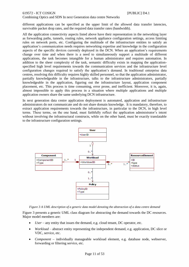

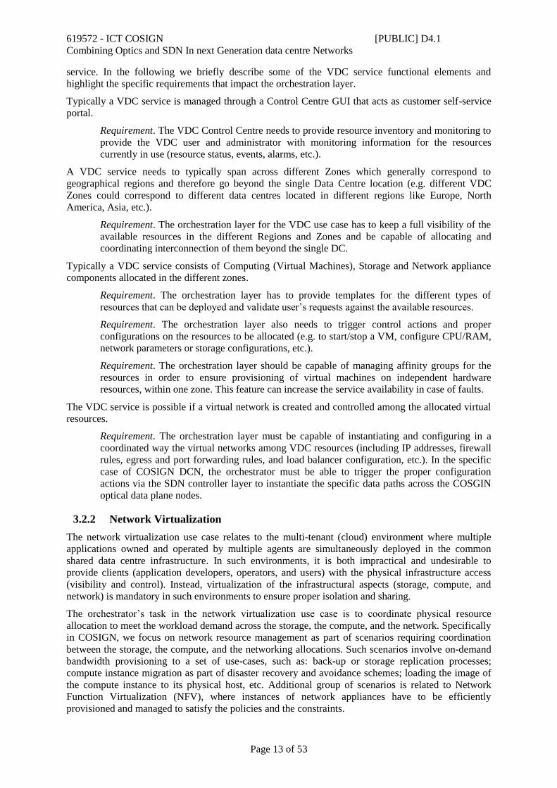


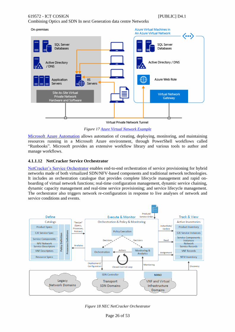
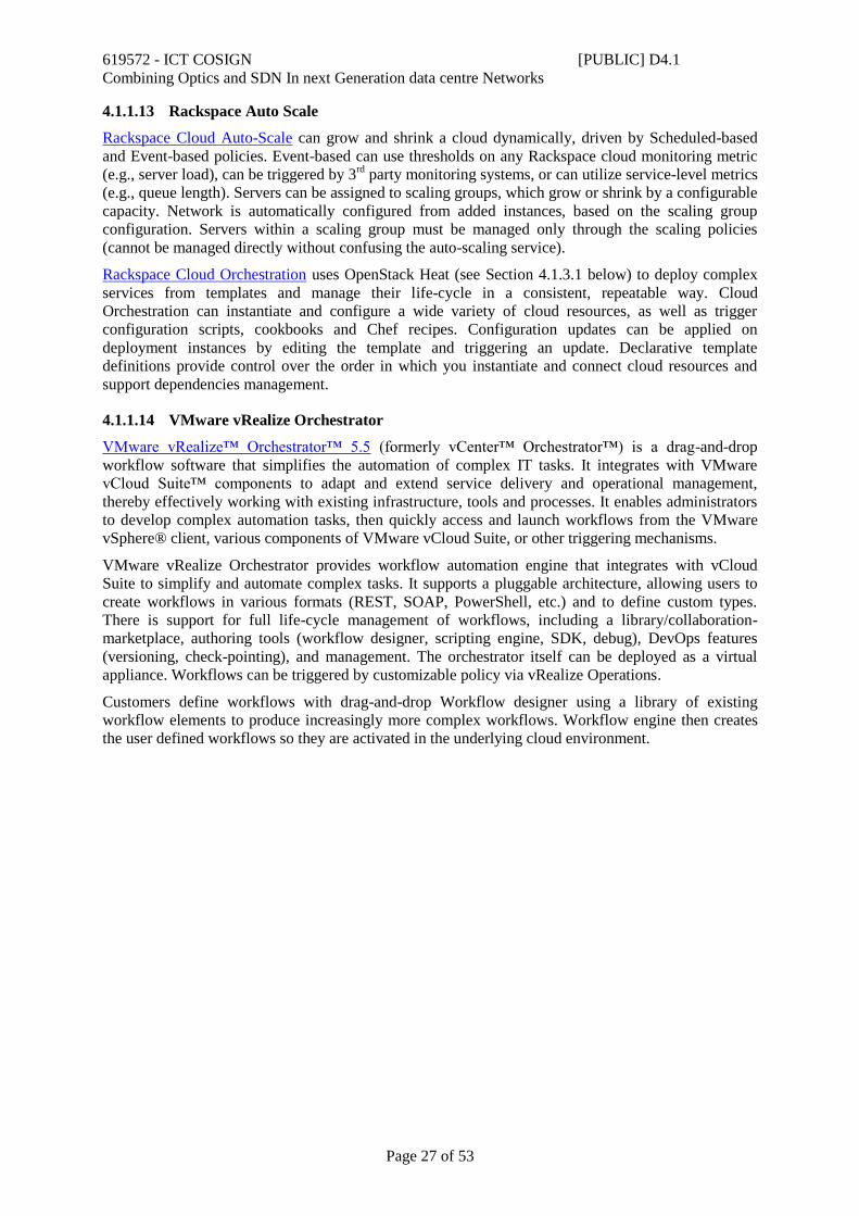
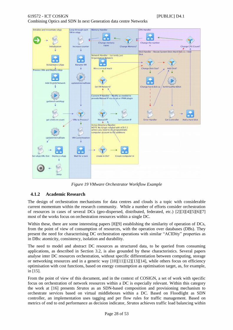
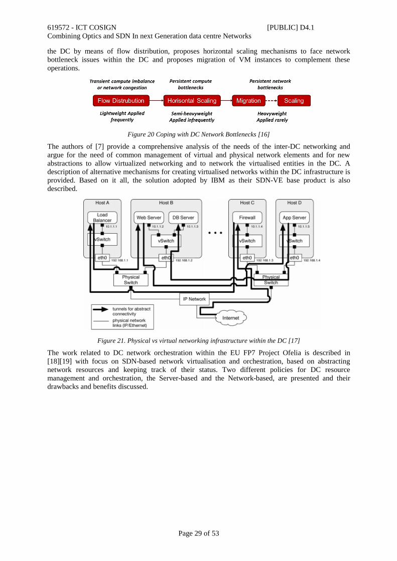

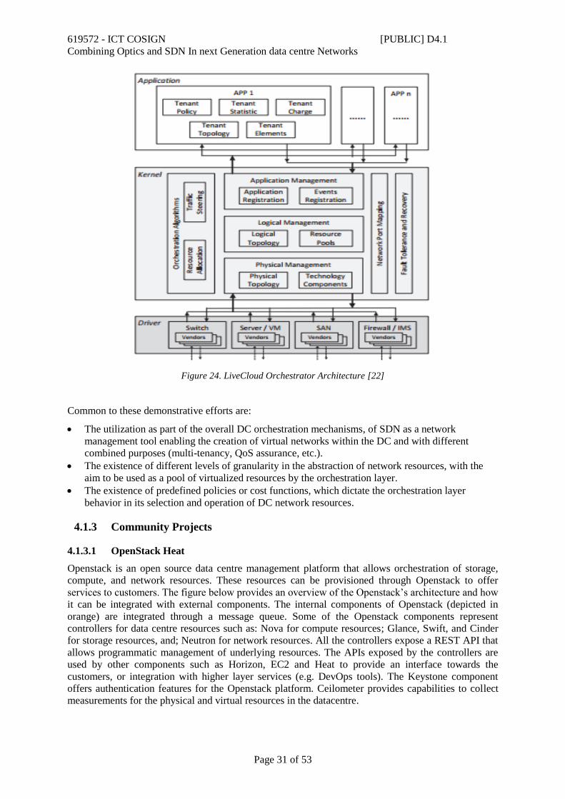
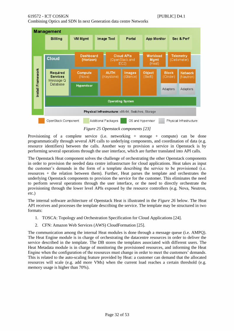

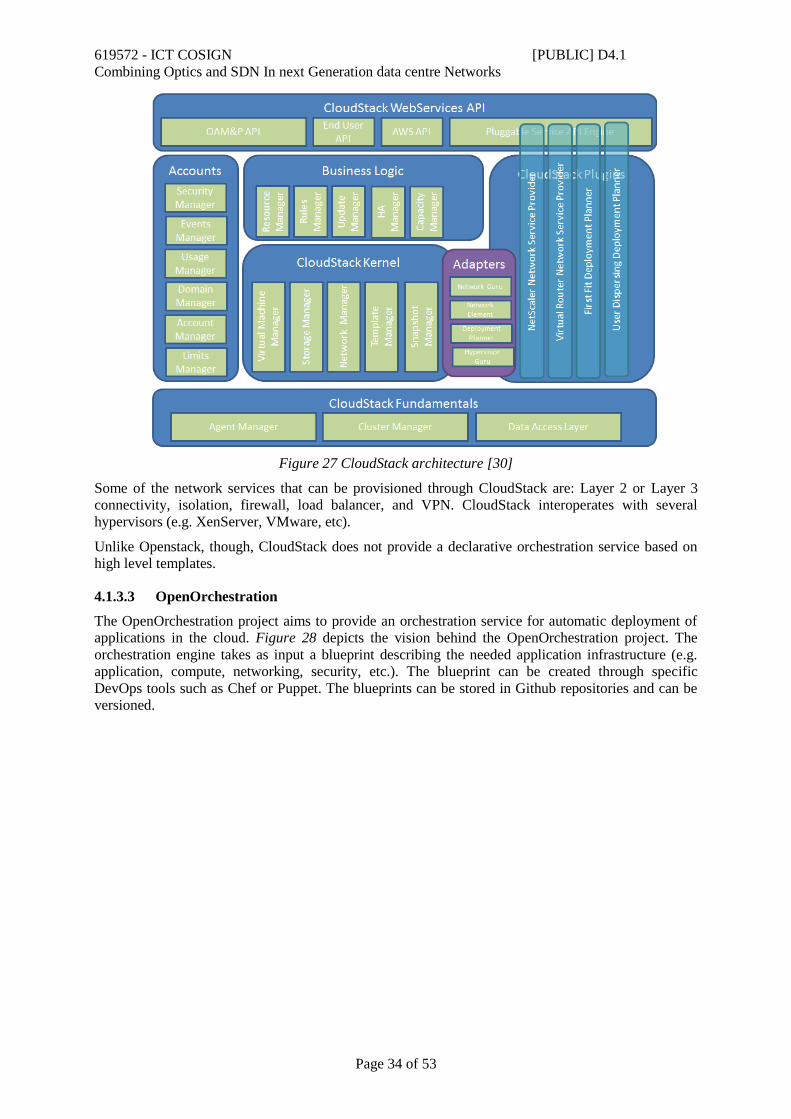


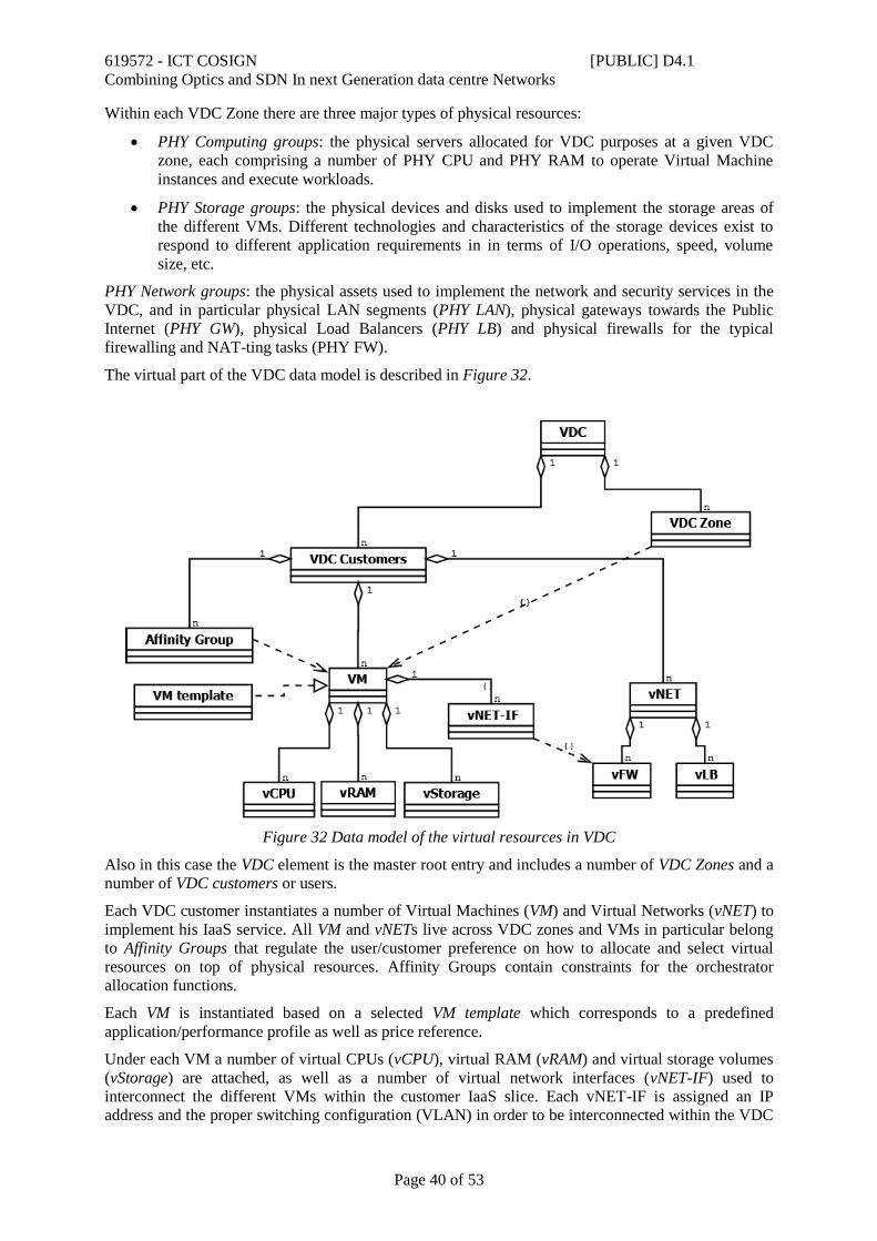

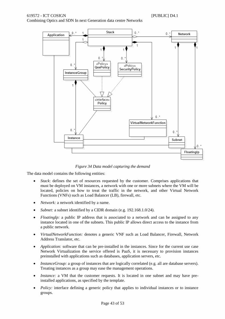
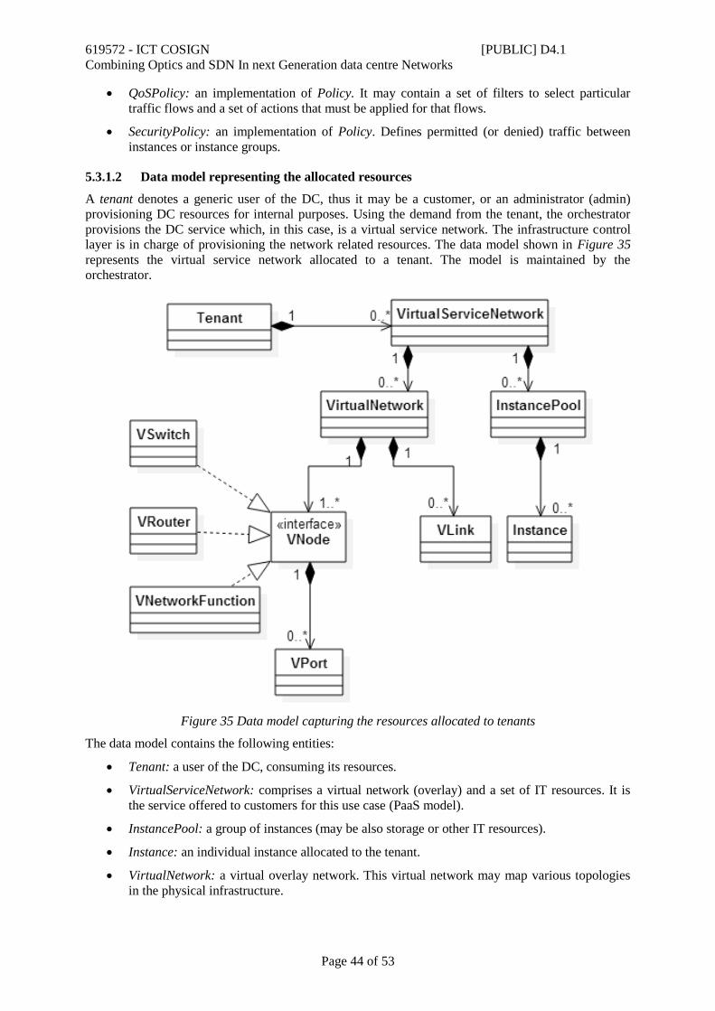
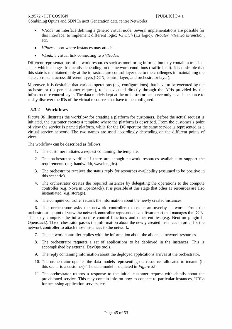
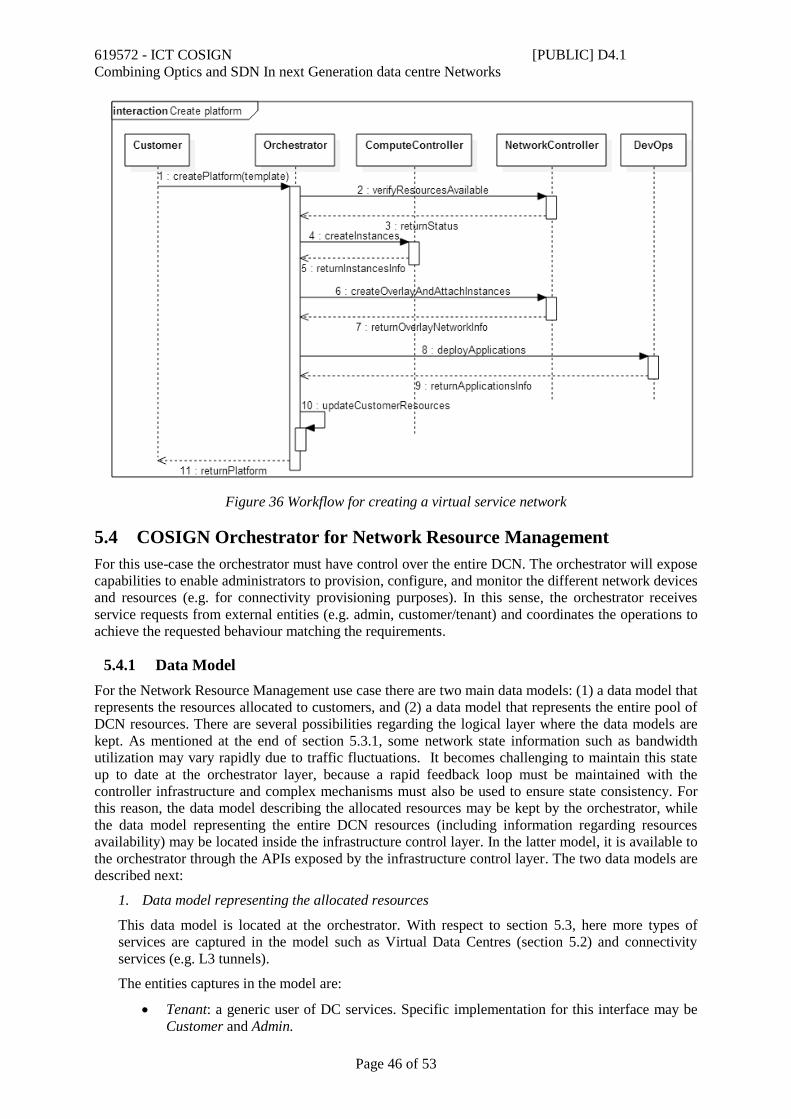


![COSIGN - European Commission : CORDIS · 619572 - ICT COSIGN [PUBLIC] D2.6 Combining Optics and SDN In next Generation data centre ...](https://static.documents.pub/doc/80x56/5b9a6e7e09d3f20b318b953f/cosign-european-commission-cordis-619572-ict-cosign-public-d26-combining.jpg)


