12
Business Unit Technology Newsletter Industrial Services Australia Solar solutions Safety in PV installations

Business Unit
Technology Newsletter
Industrial ServicesAustralia
Solar solutionsSafety in PV installations
2
Safety in PV installations
With over 30 years of experience in the Australian electrical industry, DKSH have created a best in class solar portfolio from Europe’s world leading manufacturers. Our partnership with Multi-Contact, Lapp Kabel, Wieland Electric and ABB has enabled us to be involved in the solar industry in Australia for over a decade.
Over the years we have seen many new products arrive on the market, and have some serious concerns about the quality of some of these items. When you design a system that should last 25 years, there is no excuse for using sub standard components. In fact the difference between using inferior products and premium products could be as little as $10 - $20 (total) on a $15,000 PV installation.
We have seen Multi-Contact’s MC3 and MC4 connectors copied, some copies are very poor quality and although they may work for the first year or two of an installation, serious concerns have been raised about not only the electrical connections, but also the materials they have been made from. As these connectors fail, property and life could be put at risk.
Recently sub standard DC rated circuit breakers have started to enter the market, and we have heard stories of failures at the time of installation. Some installations have had AC rated product installed. AC rated isolators are common, so too is using domestic grade flexible conduits.
Some multi-string installations have used AC fuses, or worse still, they have used polarized DC circuit breakers. In the event of a reverse current fault, a standard polarised DC circuit breaker will offer no protection, and could actually catch fire as the arc extinguishment chamber is designed to work in one direction only. DC fuses designed specifically for PV installations or non-polarised DC circuit breakers are the only products that can be used for this application.
Cable choice should be a major consideration on a PV installation. When you are dealing with 1kW or more of DC power, you should be using a cable that not only has the correct voltage rating, but also the right mechanical construction. The use of TPS for running DC should be looked at with great concern. This cable was originally designed for AC circuits, and could easily be mistaken for an AC cable in a dark rooftop, even if it does have a hand written label on it. Appropriately labelled SDI or TWIN SDI cables should be used for easy identification and to maximise mechanical protection. These cables should be flexible to reduce the risk of damage to the conductors at the time of installation, and the conductors should be tinned to lower the risk of corrosion and poor connections over an extended period of time. DKSH raised these concerns about installers using TPS for solar cabling with our German partner Lapp Kabel and together we designed the TWIN SDI cable specifically for Australian solar installations. There is no longer any reason to use TPS or non solar specific cables for DC cabling in and on Australian roof spaces.
Not only poor product choice, but also poor work practices in the last few years from some businesses have seen substandard installations carried out and customers not receive the quality they are expecting. We have spoken to numerous installation companies and can’t believe the excuses given for cutting corners to save a few cents.
Our concern for the safety of PV installations in Australia has led us to compile this publication with articles and products which leave no more reason for sub standard installations. All of these items are designed and rated for specific applications and are all of the highest quality, from well established, world leading European manufacturers.
We ask that you spend the time to read these articles, and the next time you carry out an installation and you are deciding which products to install, ask yourself, “Would I want to use this product on my family home?”
David FauxProduct Manager - SolarDKSH Australia Pty Ltd
3
Safety concerns on the use of counterfeit connectors
A growing number of suspect copies of Multi-Contact’s world renowned MC Solar components have recently appeared on the market. Comparative measurements and material tests have revealed substantial deficiencies in quality, and compromised safety and system performance.
Visually, the copies are virtually indistinguishable from the genuine MC products. Multi-Contact is defending itself on the one hand by taking court action against the imitators and on the other hand by increasing awareness to protect you and your customers from the financial and reputational damage that can result from the use of inferior products. Concerns have been highlighted about the safety characteristics such as UV-resistance, contact resistance, and material quality, that may be dangerous when installed in a PV system.
The serious problems which result from inadequate compatibility or the use of inferior copies frequently occur only after a considerable period of time has elapsed. The use of poorly matched connectors can cause contact problems that can directly or indirectly lead to a marked rise in the temperature of the plug connector due to a higher contact resistance. This can subsequently result in arcing and ultimately to a fire. This can lead to substantial damage to your professional reputation, loss of revenue from the PV system, material damage, and quite possibly personal injury.
Using copies mated with the genuine Multi-Contact connectors can result in a poor fit between insulator parts that can result in system failure due to compromised sealing against the elements such as rain or dust.
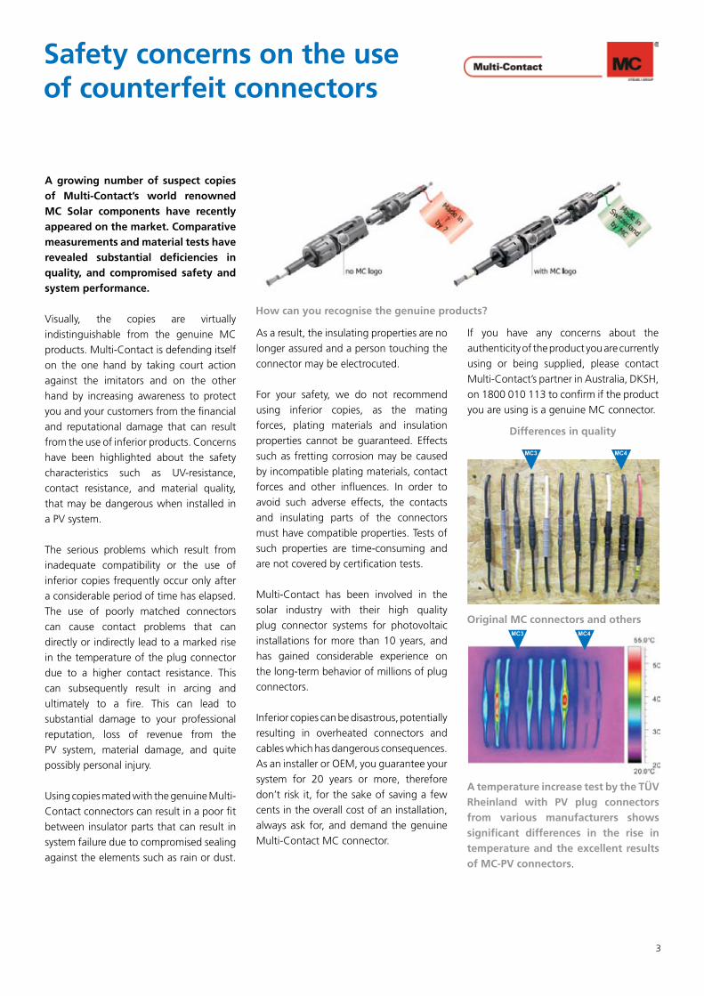
As a result, the insulating properties are no longer assured and a person touching the connector may be electrocuted.
For your safety, we do not recommend using inferior copies, as the mating forces, plating materials and insulation properties cannot be guaranteed. Effects such as fretting corrosion may be caused by incompatible plating materials, contact forces and other influences. In order to avoid such adverse effects, the contacts and insulating parts of the connectors must have compatible properties. Tests of such properties are time-consuming and are not covered by certification tests.
Multi-Contact has been involved in the solar industry with their high quality plug connector systems for photovoltaic installations for more than 10 years, and has gained considerable experience on the long-term behavior of millions of plug connectors.
Inferior copies can be disastrous, potentially resulting in overheated connectors and cables which has dangerous consequences. As an installer or OEM, you guarantee your system for 20 years or more, therefore don’t risk it, for the sake of saving a few cents in the overall cost of an installation, always ask for, and demand the genuine Multi-Contact MC connector.
If you have any concerns about the authenticity of the product you are currently using or being supplied, please contact Multi-Contact’s partner in Australia, DKSH, on 1800 010 113 to confirm if the product you are using is a genuine MC connector.
A temperature increase test by the TÜV Rheinland with PV plug connectors from various manufacturers shows significant differences in the rise in temperature and the excellent results of MC-PV connectors.
Differences in quality
How can you recognise the genuine products?
Original MC connectors and others
MC3
MC3 MC4
MC4

4
Protection
The high-performance MCB S800PV-S specially developed for use in photovoltaic systems offers reliable protection for PV modules and lines against reverse currents from defective strings and AC regenerative feedback due to defective inverters. The high demands of PV systems have been taken into consideration in the development of the S800PV-S:
More comfort:Disconnector properties for comfortableswitching even under load.
More voltage:Higher nominal voltage range up to 1200VDC (3 pole). Rated continuous current up to 125A.
More accessories:Wide range of accessories, for example for remote switching, fault signalling and external driving.
More space:Highly compact dimensions for space-saving installation on the DIN rail.
Non Polarised:Polarity independant design, can be used for string protection.
800V DC circuit breakersMaximum safety for use in photovoltaic systems
Current rating (A)
Icu (kA)
2 pole 800V DC
3 pole 1200V DC
10 5 S802PVS10 S803PVS10
13 5 S802PVS13 S803PVS13
16 5 S802PVS16 S803PVS16
20 5 S802PVS20 S803PVS20
25 5 S802PVS25 S803PVS25
32 5 S802PVS32 S803PVS32
40 5 S802PVS40 S803PVS40
50 5 S802PVS50 S803PVS50
63 5 S802PVS63 S803PVS63
80 5 S802PVS80 S803PVS80
100 5 S802PVS100 S803PVS100
125 5 S802PVS125 S803PVS125
440/500V DC circuit breakersMaximum safety for use in photovoltaic systems
ABB’s well established System proM S280 range of MCBs (miniature circuit breakers) has been further extended to include UC (Universal Current versions) which feature the K tripping characteristic which is the optimal solution for the safe protection of cables. A permanent magnet assists in the forced extinguishing of the DC arc.
Rated voltage:440V•
Maximum operating voltage:500V•
Current rating (A)
Icn (kA)
2 pole 440/500V DC
6 6 S282UCK6
8 6 S282UCK8
10 6 S282UCK10
16 6 S282UCK16
20 6 S282UCK20
25 6 S282UCK25
32 6 S282UCK32
40 6 S282UCK40
Locking device:Prevents unauthorized operation of the operating lever. Suits 3mm Ø padlockPart number: SA1
Locking device:Prevents unauthorized operation of the operating lever. Suits 4mm Ø padlock
Part number: S800-PLL
5
Protection
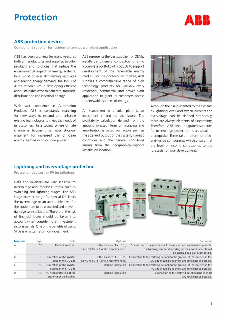
Cells and inverters are very sensitive to overvoltage and impulse currents, such as switching and lightning surges. The ABB surge arrester range for special DC limits the overvoltage to an acceptable level for the equipment to be protected and prevent damage to installations. Therefore, the risk of financial losses should be taken into account when considering an investment in solar panels. One of the benefits of using SPDs is a better return on investment.
Lightning and overvoltage protectionProtection devices for PV installations
Location Type Role Options Comment
A DC Protection of cells If the distance L1 < 10 m, only OVR PV in A or B is recommended.
Connection to the chassis should be as short and rectilinear as possible. The lightning arrester depending on the environment should
be installed in a leak-proof casing.
B DC Protection of the inverter input on the DC side
If the distance L1 < 10 m, only OVR PV in A or B is recommended.
Connection to the earthing bar and to the ground of the inverter on the DC side should be as short and rectilinear as possible.
C AC Protection of the inverter output on the AC side
Routine installation Connection to the earthing bar and to the ground of the inverter on the AC side should be as short and rectilinear as possible.
D AC AC head protection at the entrance of the building
Routine installation Connection to the earthing bar should be as short and rectilinear as possible.
ABB protection devicesComponent supplier for residential and power plant application
ABB has been working for many years, as both a manufacturer and supplier, to offer products and solutions that reduce the environmental impact of energy systems. In a world of ever diminishing resources and soaring energy demand, the focus of ABB’s research lies in developing efficient and sustainable ways to generate, transmit, distribute and use electrical energy.
With vast experience in Automation Products, ABB is constantly searching for new ways to expand and enhance existing technologies to meet the needs of its customers. In a society where climate change is becoming an ever stronger argument for increased use of clean energy, such as wind or solar power.
ABB represents the best supplier for OEMs, installers and general contractors, offering a complete portfolio of products to support development of the renewable energy market. For the photovoltaic market, ABB supplies a comprehensive range of high technology products for virtually every residential, commercial and power plant application to grant its customers access to renewable sources of energy.
An investment in a solar plant is an investment in and for the future. The profitability calculation derived from the amount invested, term of financing and amortisation is based on factors such as the size and output of the system, climatic conditions and the general conditions arising from the geographical/regional installation location.
Although the risk presented to the systems by lightning, over- and reverse currents and overvoltage can be defined statistically, there are always elements of uncertainty. Therefore, ABB sees integrated solutions for overvoltage protection as an absolute prerequisite. These take the form of tried-and-tested components which ensure that the level of income corresponds to the forecasts for your development.

6
Lapp
Olfl
ex Solar X
LSLap
p V
90HT TW
INTh
ermo
Plastic Sheath
(TPS)
Cab
le Co
nstru
ction
Co
nd
ucto
rM
aterialTinned C
opperTinned C
opperC
opper
Strand
ing
Class 5 Flexible
Class 5 Flexible
Class 2 Stranded
Insu
lation
Material
Electron beamed X
-linked polyolefinPV
C (V
90HT)
PVC
(V90)
Sheath
Material
Electron beamed X
-linked Co-polym
erePV
C (V
90HT)
PVC
(3V90)
Techn
ical data
No
min
al Vo
ltage A
C600/1000V
600/1000V450/750V
No
min
al Vo
ltage D
C900/1500V
900/1500V675/1125V
Ap
plicatio
n C
riteriaW
eather R
esistance
ExcellentG
oodPoor
UV
Resistan
ceExcellent
ExcellentN
one
Flexibility
ExcellentExcellent
Poor
Ab
rasion
Resistan
ceExcellent
Good
Good
Halo
gen
FreeYes
No
No
Am
mo
nia G
as Resistan
ceExcellent
Not Tested
Unknow
n
Therm
al End
uran
ce TestExcellent
Not Tested
Unknow
n
Dam
p h
eat resistance test EN
60068-2-78 w
ith 85%
hu
mid
ityExcellent
Not Tested
Unknow
n
Labeled
for So
lar app
lication
YesYes
No
Desig
ned
specifi
cally for
DC
Solar - PV m
odules to inverterD
C Solar - w
iring from rooftop to inverter
AC
circuit wiring
Ro
ofto
p w
iring
from
PV m
od
ules
YesC
an be used, but XLS is recom
mended
No
Ro
ofto
p to
inverter w
iring
YesYes
Not Recom
mended
No
tesX
LS provides maxim
um protection
•against w
eather, UV
and abrasion resistance Flexible and easy to use.
•Tinned conductors resist corrosion
•
Once split, each conductor retains
•double insulation G
ood UV
resistance •
Flexible and easy to use. •
Tinned conductors resist corrosion•
Voltage ratings lower than solar
•cables. Bare copper conductors could pose a threat from
corrosion. N
ot very flexible. •
Could be m
istaken for standard •
power cables if not labeled
correctly and leave installer liable for dam
ages. Tim
e consuming due to lack of
•labelling. O
nce split, is only single insulated. •
Solar C
able Selectio
n G
uid
e
7
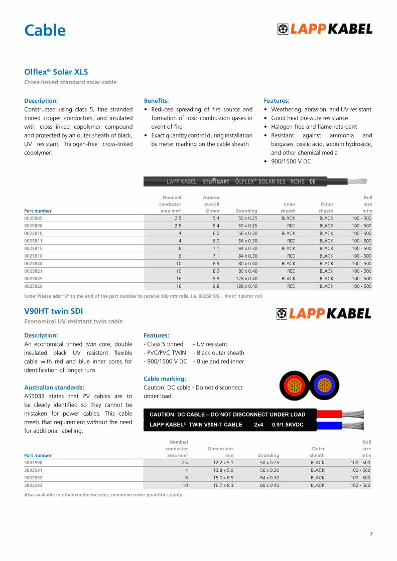
Olflex® Solar XLSCross-linked standard solar cable
Part number
Nominal conductor area mm2
Approx overall Ø mm Stranding
Inner sheath
Outer sheath
Roll size
mtrs
0025805 2.5 5.4 50 x 0.25 BLACK BLACK 100 - 500
0025806 2.5 5.4 50 x 0.25 RED BLACK 100 - 500
0025810 4 6.0 56 x 0.30 BLACK BLACK 100 - 500
0025811 4 6.0 56 x 0.30 RED BLACK 100 - 500
0025815 6 7.1 84 x 0.30 BLACK BLACK 100 - 500
0025816 6 7.1 84 x 0.30 RED BLACK 100 - 500
0025820 10 8.9 80 x 0.40 BLACK BLACK 100 - 500
0025821 10 8.9 80 x 0.40 RED BLACK 100 - 500
0025825 16 9.8 128 x 0.40 BLACK BLACK 100 - 500
0025826 16 9.8 128 x 0.40 RED BLACK 100 - 500
Description: Constructed using class 5, fine stranded tinned copper conductors, and insulated with cross-linked copolymer compound and protected by an outer sheath of black, UV resistant, halogen-free cross-linked copolymer.
Benefits:Reduced spreading of fire source and •formation of toxic combustion gases in event of fireExact quantity control during installation •by meter marking on the cable sheath
Features: Weathering, abrasion, and UV resistant•Good heat pressure resistance•Halogen-free and flame retardant•Resistant against ammonia and •biogases, oxalic acid, sodium hydroxide, and other chemical media900/1500 V DC•
Cable
Note: Please add “S” to the end of the part number to receive 100 mtr rolls, i.e. 0025810S = 4mm2 100mtr roll
Description: An economical tinned twin core, double insulated black UV resistant flexible cable with red and blue inner cores for identification of longer runs.
Australian standards:AS5033 states that PV cables are to be clearly identified so they cannot be mistaken for power cables. This cable meets that requirement without the need for additional labelling.
Features:- Class 5 tinned - UV resistant- PVC/PVC TWIN - Black outer sheath- 900/1500 V DC - Blue and red inner
Cable marking:Caution: DC cable - Do not disconnect under load.
V90HT twin SDIEconomical UV resistant twin cable
Part number
Nominal conductor area mm2
Dimensions mm Stranding
Outer sheath
Roll size
mtrs
3803590 2.5 12.2 x 5.1 50 x 0.25 BLACK 100 - 500
3803591 4 13.8 x 5.9 56 x 0.30 BLACK 100 - 500
3803592 6 15.0 x 6.5 84 x 0.30 BLACK 100 - 500
3803593 10 16.7 x 8.3 80 x 0.40 BLACK 100 - 500
CAUTION: DC CABLE – DO NOT DISCONNECT UNDER LOAD
LAPP KABEL® TWIN V90H-T CABLE 2x4 0.9/1.5KVDC
Also available in other conductor sizes, minimum order quantities apply

8
PV Fuse Warning -Incorrectly using AC fuses in DC circuits
Not all fuses are created equally. Using the incorrect fuse in the wrong circuit could have potentially disastrous consequences to equipment and people.
Why use a fuse?A fuse is an overcurrent device that is designed to sacrifice itself to protect electrical systems. Fuses are designed to open circuits when put under stress by excessive current flow caused by overloads or faults.Choosing the right fuse for the application will prevent fires and other damage caused when something goes wrong. Typical problems may include: a cable coming loose in the inverter circuit, a cable shorting to Earth, accidental cutting of a cable, an animal chewing through cabling, or weather damage.
Fuse RatingsFuses are rated by current, and voltage and are usually rated solely for AC, solely for DC or rated for both AC and DC. If the incorrect fuses are used for DC applications the voltage rating may need to be derated and you would have to consult the fuse manufacturer for further information on their product. This is because of the greater arc energy that needs to be absorbed during the breaking process.
The difference between AC and DC fusesAlternating currents are quite simple for a fuse to break as the alternating current source reverses the flow of electrons 100 times a second on 50Hz circuits. When the current reverses, it goes to zero in magnitude. A zero current flow is very easy for a fuse to interrupt – at this point, the current flow has stopped and there is no longer any energy to sustain the arc
across the melted fuse element.Direct currents, on the other hand can be very difficult to break. As the name implies, the current flows in a constant direction. There is no zero point to aid the fuse in extinguishing the arc. DC fuses are relatively sophisticated devices that have a different construction to simple AC fuses, DC fuses contain additional elements to extinguish the arc.
For AC and DC fuses, the standard rated voltages are different and there is no strict mathematical relationship between them. A fuse rated at 500V AC may be rated at 250V DC or 440V DC, dependant on construction. As a general rule of thumb, a standard AC fuse will need to be derated by 50% i.e. 500V AC would be rated at 250V DC, however you should consult the fuse manufacturer for the test results or further specifications on each fuse before making any assumptions.
AC fuses are generally designed to take a load in excess of their rated current, sometimes 160-200% of their rated value for up to 10 seconds. Within a PV system, current is limited by the constant
current source design of the PV modules, obtaining enough current to break an AC rated fuse in a reasonable amount of time could be quite difficult.
DC rated fuses designed specifically for PV applications are designed to break at the rated current in a short time, providing maximum protection for cabling, junction boxes and PV modules.
If the fuse product does not state the DC rating on the fuse or on the product specification sheet then it could be that it is not approved for use in DC applications, that the product has not been approved by an internationally recognized electrical approval body or by the manufacturer who may or may not have the testing facilities to conduct the product test. Fuse holders should also be inspected for a DC rating. To protect yourself and your customers, always use the correct DC rated product for your PV installations, if you use an incorrectly rated product, you could be liable for any damage caused or loss of life, in the event of something going wrong. AS/NZS 5033-2005 states that fuses used in a PV array shall be rated for DC use.
9
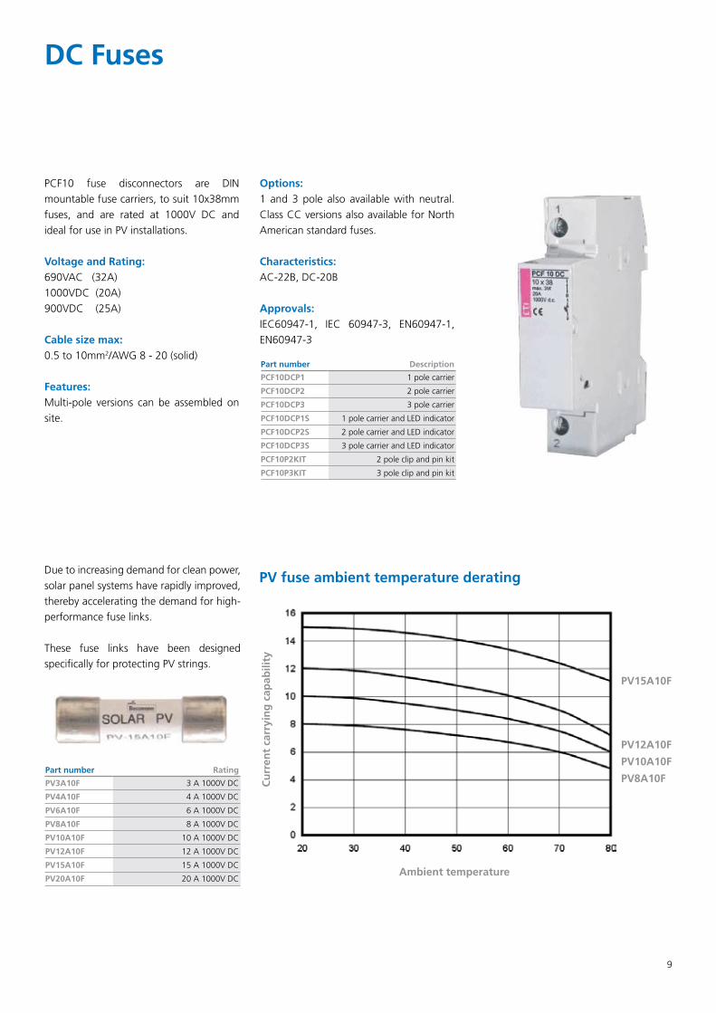
DC Fuses
PCF10 fuse disconnectors are DIN mountable fuse carriers, to suit 10x38mm fuses, and are rated at 1000V DC and ideal for use in PV installations.
Voltage and Rating: 690VAC (32A)1000VDC (20A)900VDC (25A)
Cable size max: 0.5 to 10mm2/AWG 8 - 20 (solid)
Features: Multi-pole versions can be assembled on site.
Options: 1 and 3 pole also available with neutral. Class CC versions also available for North American standard fuses.
Characteristics: AC-22B, DC-20B
Approvals: IEC60947-1, IEC 60947-3, EN60947-1, EN60947-3
Part number Description
PCF10DCP1 1 pole carrier
PCF10DCP2 2 pole carrier
PCF10DCP3 3 pole carrier
PCF10DCP1S 1 pole carrier and LED indicator
PCF10DCP2S 2 pole carrier and LED indicator
PCF10DCP3S 3 pole carrier and LED indicator
PCF10P2KIT 2 pole clip and pin kit
PCF10P3KIT 3 pole clip and pin kit
Due to increasing demand for clean power, solar panel systems have rapidly improved, thereby accelerating the demand for high-performance fuse links.
These fuse links have been designed specifically for protecting PV strings.
Part number Rating
PV3A10F 3 A 1000V DC
PV4A10F 4 A 1000V DC
PV6A10F 6 A 1000V DC
PV8A10F 8 A 1000V DC
PV10A10F 10 A 1000V DC
PV12A10F 12 A 1000V DC
PV15A10F 15 A 1000V DC
PV20A10F 20 A 1000V DC
PV15A10F
PV12A10F
PV10A10F
PV8A10FCu
rren
t ca
rryi
ng
cap
abili
ty
Ambient temperature
PV fuse ambient temperature derating

10
As PV system designs become larger to maximize return on investments, the need for PV string protection is becoming more common.
We are proud to announce the release of a new string protection system. Available in numerous current ratings, these PV String Fuse Boxes are manufactured with premium components. Fusing is rated at 1000V DC and designed specifically for PV systems.
Most DC rated circuit breakers are polarised and are not suitable for string protection, therefore fusing is required.
No more need to spend hours in the workshop building these units when you could invest your time in more profitable exercises.
BenefitsGenuine MultiContact MC4 connectors•1000V DC rated fuses•0.6/1kV Lapp cabling•Available in numerous configurations•Plug and play •Unit is supplied complete•One, Two and Three string designs•Custom versions also available•
Current rating (A) 1 String Fuse Box 2 String Fuse Box 3 String Fuse Box4A XPMC4FUSE1/4A XPMC4FUSE2/4A XPMC4FUSE3/4A6A XPMC4FUSE1/6A XPMC4FUSE2/6A XPMC4FUSE3/6A8A XPMC4FUSE1/8A XPMC4FUSE2/8A XPMC4FUSE3/8A10A XPMC4FUSE1/10A XPMC4FUSE2/10A XPMC4FUSE3/10A12A XPMC4FUSE1/12A XPMC4FUSE2/12A XPMC4FUSE3/12A15A XPMC4FUSE1/15A XPMC4FUSE2/15A XPMC4FUSE3/15A
String Protection

11
Liquid tight IP 68 conduit
RORHflex® PA6 Conduit
Part number Conduit size Outer Ø mm Inner Ø mm Coil length mtrs
0233.202.010 M12 13.0 10.0 50m
0233.202.012 M16 15.8 12.0 50m
0233.202.016 M20 21.2 16.5 50m
0233.202.023 M25 28.5 23.0 50m
0233.202.029 M32 34.5 29.0 25m
0233.202.036 M40 42.5 36.0 25m
0233.202.048 M50 54.5 48.0 25m
Application:Due to the long life span of PV arrays, Industrial grade conduit should be used to maximise the life of your installation, don’t risk domestic or commercial grade conduit on PV installations.
Construction: Internally and externally corrugated PA6 plastic tubing.
Temperature range:-30oC to +100oC
Colour:Black.
Protection class:Conduit: IP68Fittings: IP65 - IP67
Properties:Oil resistant up to + 80• o CBenzine resistant•Highly resistant to acid and solvents•Free of silicone, cadmium, halogen•Flame retardant, self-extinguishing•UV-resistant•
ROHRflex® PA6Industrial standard conduit
Part number For conduit size Thread size Pack qty
RQW1-M (IP 65)
5020.051.212 M12 M12 50
5020.051.218 M16 M16 50
5020.051.222 M20 M20 50
RQB90-M (90o Bend - IP 67)
5103.013.216 M16 M12 50
5103.015.220 M16 M20 50
5103.021.220 M20 M20 50
5103.028.225 M25 M25 25
5103.034.232 M32 M32 25
5103.042.240 M40 M40 10
5103.054.250 M50 M50 5
RQB1 45-M (45o Bend - IP 65)
5101.013.216 M16 M12 50
5101.021.220 M20 M20 50
5101.042.240 M 40 M 40 10
Locknuts to suit fittings
Part number Thread size Pack qty
5311 9100 M12 100
5311 9110 M16 100
5311 9120 M20 100
5311 9130 M25 100
Mounting clip - RQS (One piece clamp)
Part number For conduit size Pack qty
5030.020.209 M12 50
5030.020.211 M16 50
5030.020.216 M20 25
5030.020.221 M25 25
5030.020.229 M32 25
5030.020.236 M40 25
5030.020.248 M50 10
FLEXAquick fittings - no assembly tools required!
RQG1-M (Straight - IP 66)
Part number For conduit size Thread size Pack qty
5020.055.214 M12 M16 50
5020.055.216 M16 M16 50
5020.055.218 M16 M20 50
5020.055.220 M20 M20 50
5020.055.222 M20 M25 50
5020.055.225 M25 M25 25
5020.055.228 M25 M32 25
5020.055.232 M30 M32 25
5020.055.240 M40 M40 25
5020.055.250 M50 M50 10
Other industrial conduit types also available

DKSH Australia Pty. Ltd.14-17 Dansu Court, Hallam VIC 3803, Australiawww.dksh.com/australia
Customer Service: 1800 010 113 Fax: (03) 9554 6677S.A. Customers: (08) 8440 1300 Fax: (08) 8241 5134W.A. Customers: (08) 6254 5900 Fax: (08) 9277 8755


