Busway Systems Catalog 5600CT9101R10/17 2017 Class 5600 Powerbus™ 100-400 A I-Line™ Plug-in Busway 225-600 A Feeder Style Plug-in Style I-Line II Busway 800-5000 A I-Line Plug-in Units Power-Zone™ Busway
SECTION 2: I-LINE™ CONSTRUCTION .........................................................................19
Plug-In Busway 225–600 A ........................................................................................................... 19Plug-In Busway 800–5000 A ......................................................................................................... 20Indoor Feeder Busway 800–5000 A .............................................................................................. 21Outdoor Feeder Busway 800–5000 A ........................................................................................... 22Busway Order Entry Checklist ....................................................................................................... 23
SECTION 3: I-LINE™ APPLICATION DATA ...................................................................24
The Four Types of Busway Runs .................................................................................................. 24Service Entrance Run .............................................................................................................. 24Plug-In Type Vertical Riser ...................................................................................................... 24Plug-In Type Horizontal Run ................................................................................................... 25Feeder Type Tie Run ............................................................................................................... 25
Plug-In Busway Horizontal Run ..................................................................................................... 30Phasing .................................................................................................................................... 30Identification ............................................................................................................................ 30
Plug-In Risers ................................................................................................................................ 31Dimensions .............................................................................................................................. 31Riser Installation and Phasing ................................................................................................. 32Special Manufacturer’s Recommendation ............................................................................... 32Plug-In Units ............................................................................................................................ 32Hangers ................................................................................................................................... 32
Feeder Runs .................................................................................................................................. 33Busway Through Walls and Floors .......................................................................................... 33
SECTION 4: I-LINE™ LAYOUT AND MEASUREMENT .................................................34
Known Information ........................................................................................................................ 34
SECTION 5: I-LINE™ INSTALLATION, SPECIAL FEATURES, AND SERVICES ........ 37
Installation Recommendations ...................................................................................................... 37Painting Installed Busway Systems ............................................................................................... 37Hanger Spacing ............................................................................................................................. 37Maintenance Recommendations ................................................................................................... 38Special Busway Construction ........................................................................................................ 39
Special Paint ............................................................................................................................ 39Low Current Density Busway ................................................................................................... 39Riser Plug-In Busway ............................................................................................................... 39Splash Resistant Busway ........................................................................................................ 39Harmonic Busway .................................................................................................................... 39Seismically Qualified Busway ..................................................................................................40
Services ......................................................................................................................................... 40Busway Measuring and Layout Service ................................................................................... 40Emergency Service .................................................................................................................. 40“Missing Link” Program ............................................................................................................ 41How To Properly Measure Your Missing Link Dimensions ...................................................... 41
SECTION 6: I-LINE™ ELECTRICAL DATA ................................................................... 42
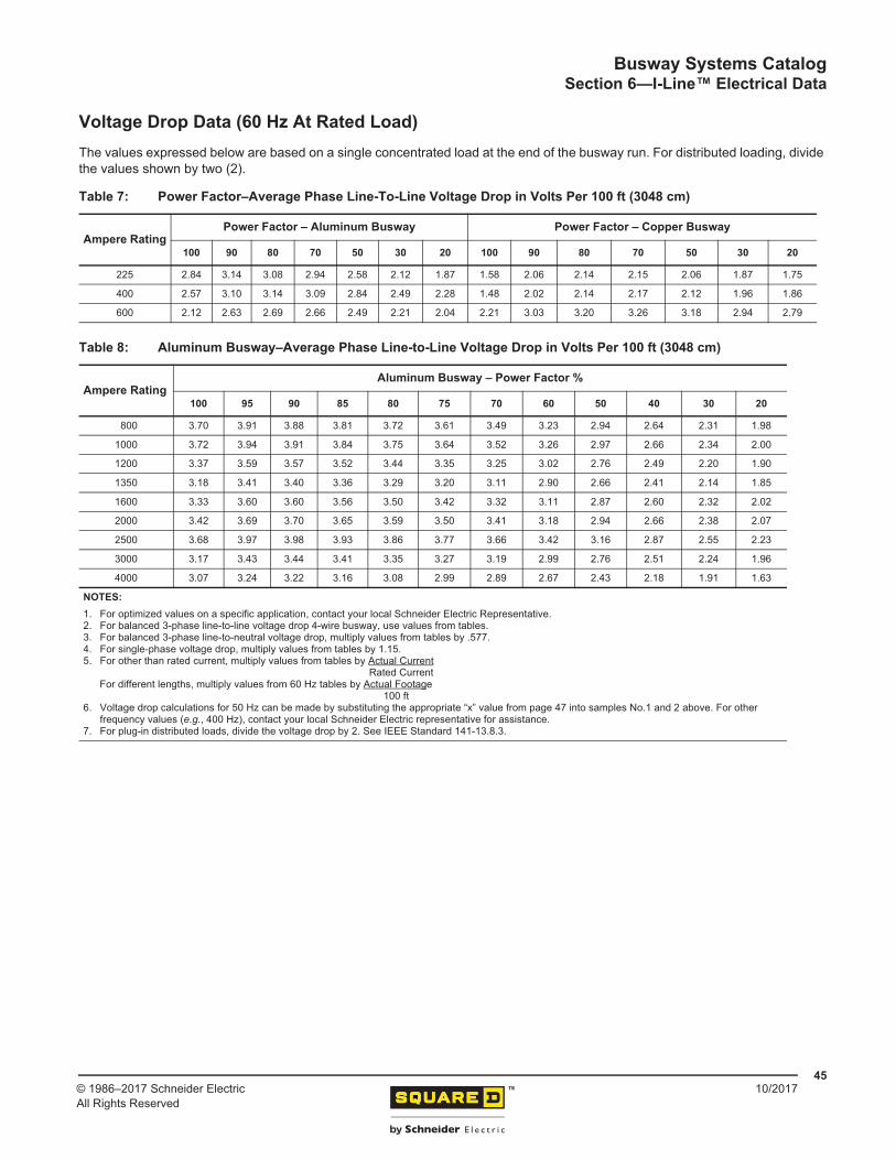
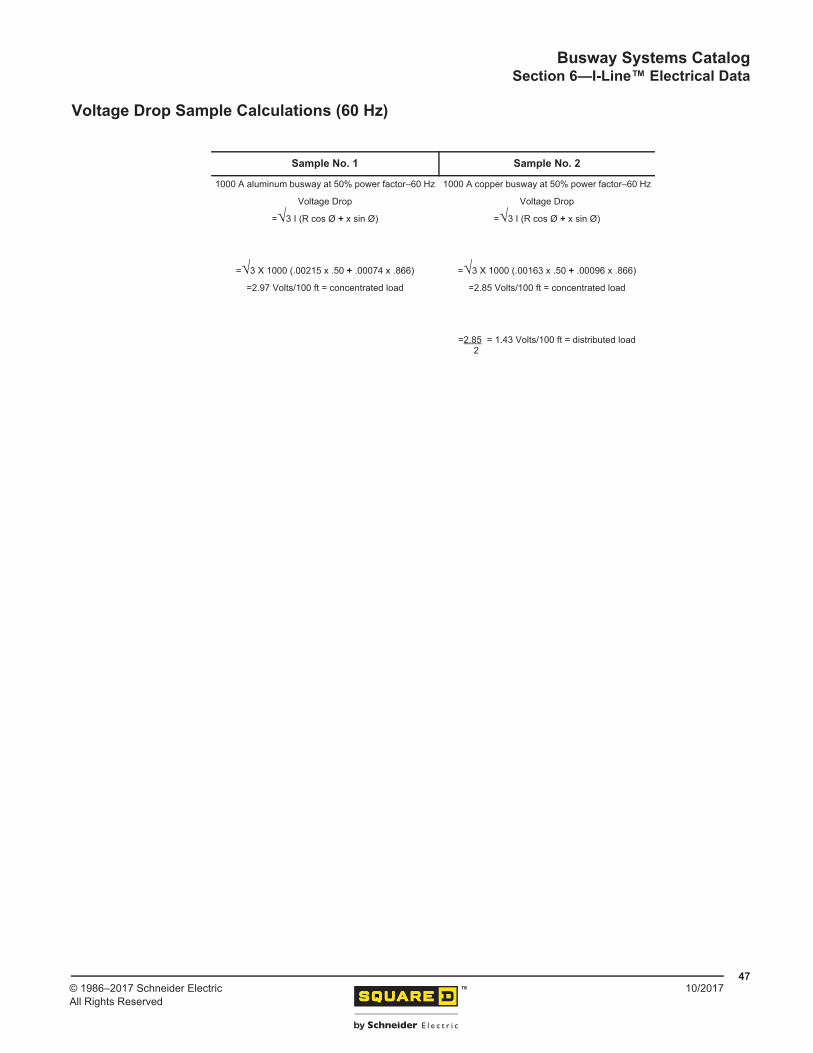
Voltage Drop Data (60 Hz At Rated Load) .................................................................................... 45Voltage Drop Sample Calculations (60 Hz) ................................................................................... 47
SECTION 7: I-LINE™ 225–600 A BUSWAY .................................................................. 48
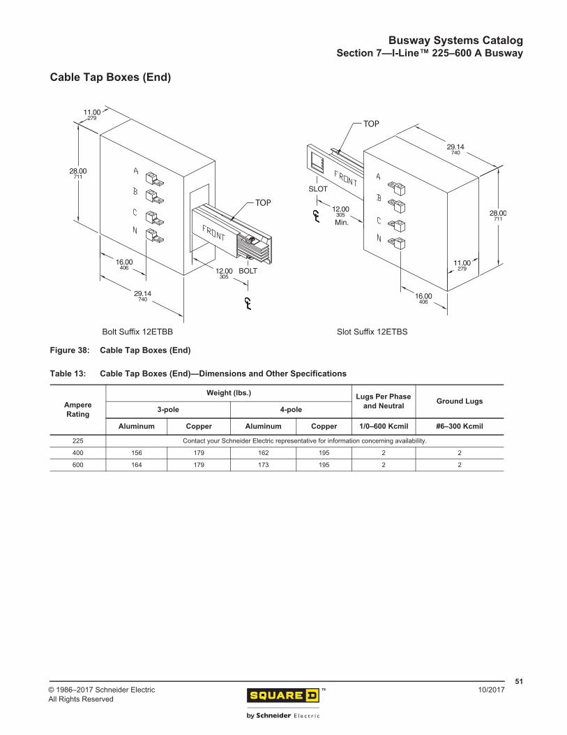
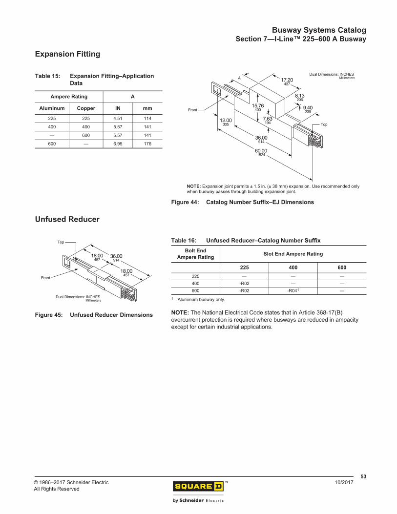
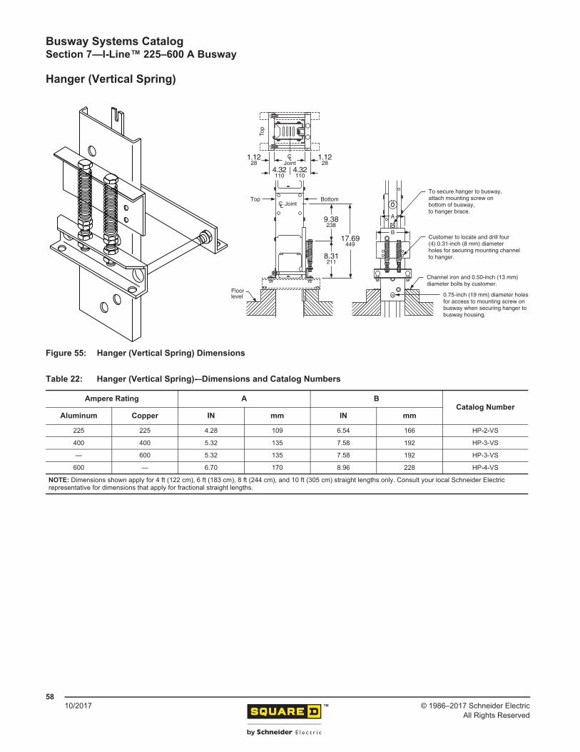
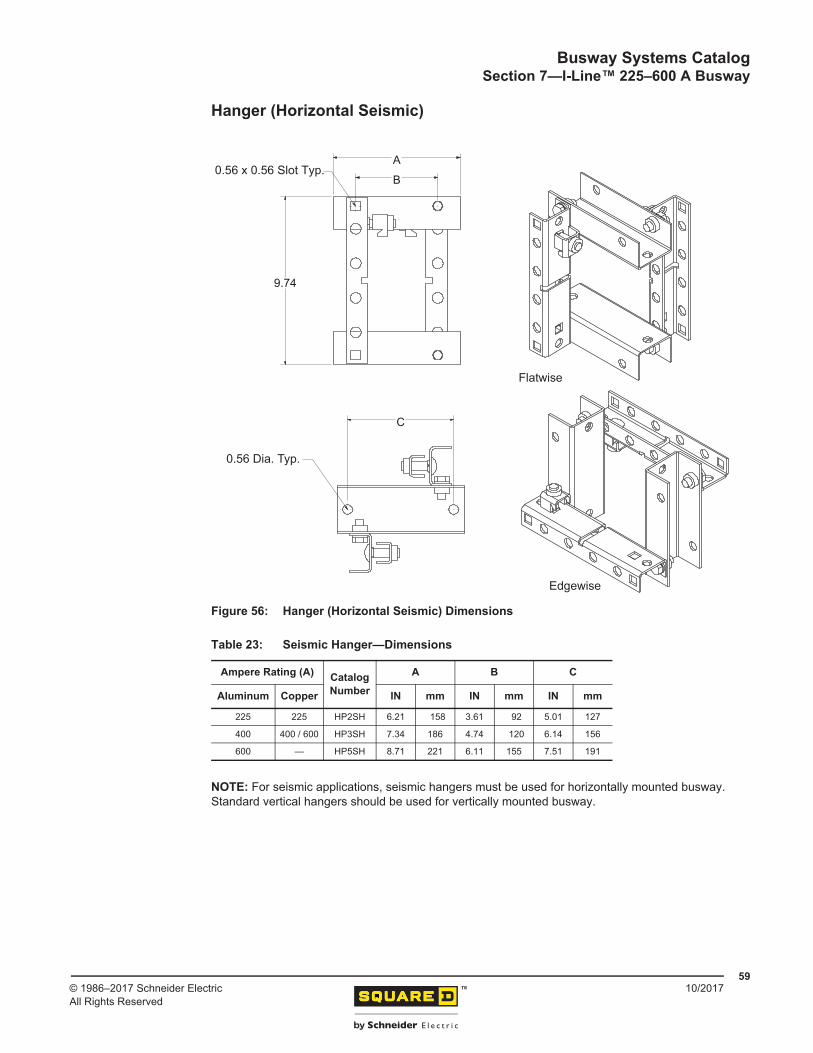
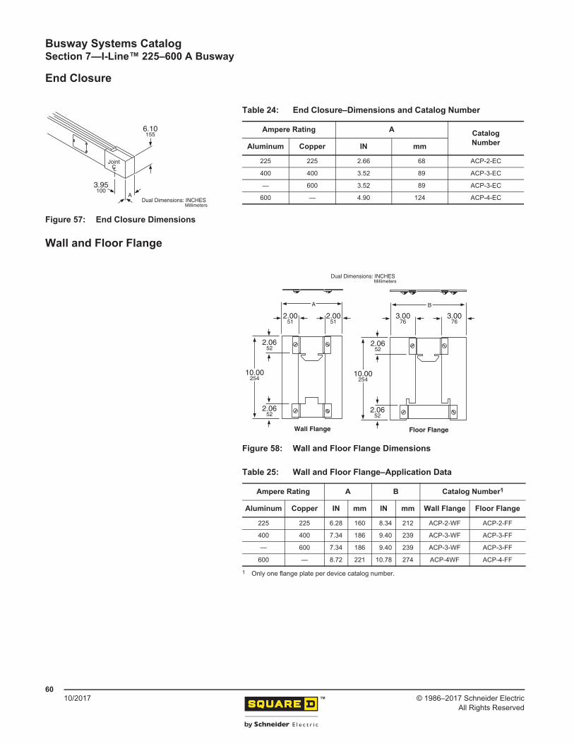
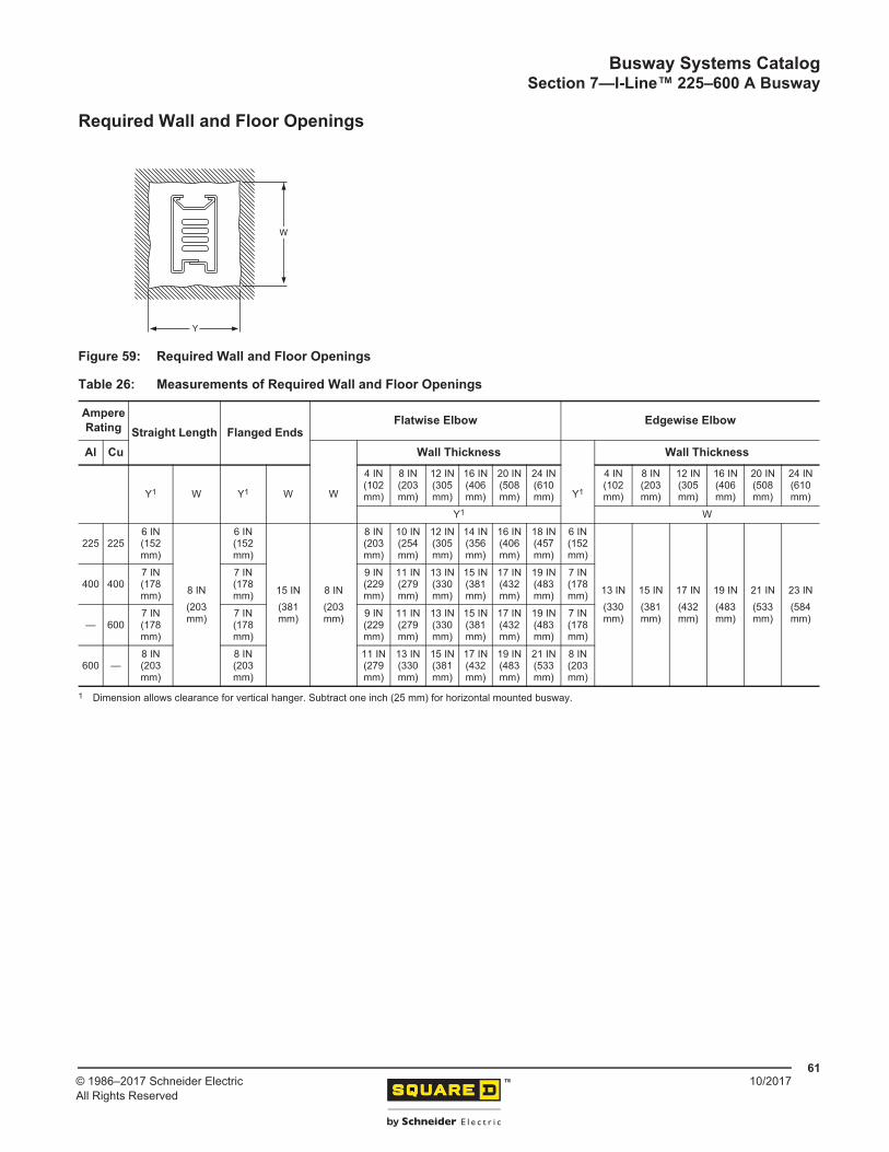
I-Line™ 225–600 A Busway Catalog Numbering System ............................................................. 48Straight Lengths ............................................................................................................................ 49Cross Section ................................................................................................................................ 49Joint Detail ..................................................................................................................................... 50Cable Tap Boxes (Plug-In) ............................................................................................................ 50Cable Tap Boxes (End) ................................................................................................................. 51Tees ............................................................................................................................................... 52Elbows ........................................................................................................................................... 52Expansion Fitting ........................................................................................................................... 53Unfused Reducer ........................................................................................................................... 53Flanged End Cutout and Drilling Template .................................................................................... 54Flanged End Details ...................................................................................................................... 54Flatwise Hanger ............................................................................................................................. 55Edgewise Hanger .......................................................................................................................... 55Sway Brace Collar ......................................................................................................................... 56Hanger (Vertical Fixed) .................................................................................................................. 57Hanger (Vertical Spring) ................................................................................................................ 58Hanger (Horizontal Seismic) .......................................................................................................... 59End Closure ................................................................................................................................... 60Wall and Floor Flange ................................................................................................................... 60Required Wall and Floor Openings ............................................................................................... 61
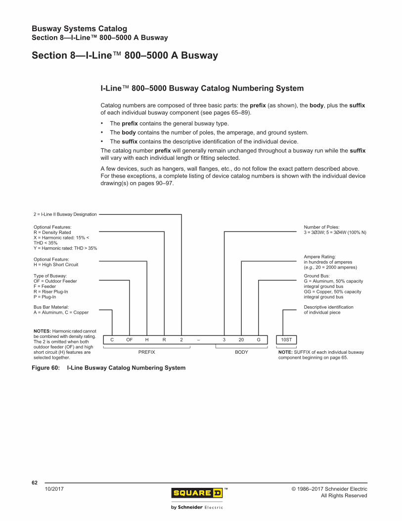
SECTION 8: I-LINE™ 800–5000 A BUSWAY ................................................................ 62
I-Line™ 800–5000 Busway Catalog Numbering System .............................................................. 62Cross Sections—Plug-In and Indoor Feeder Lengths .................................................................. 63Cross Sections—Fittings and All Outdoor Feeder ........................................................................ 63
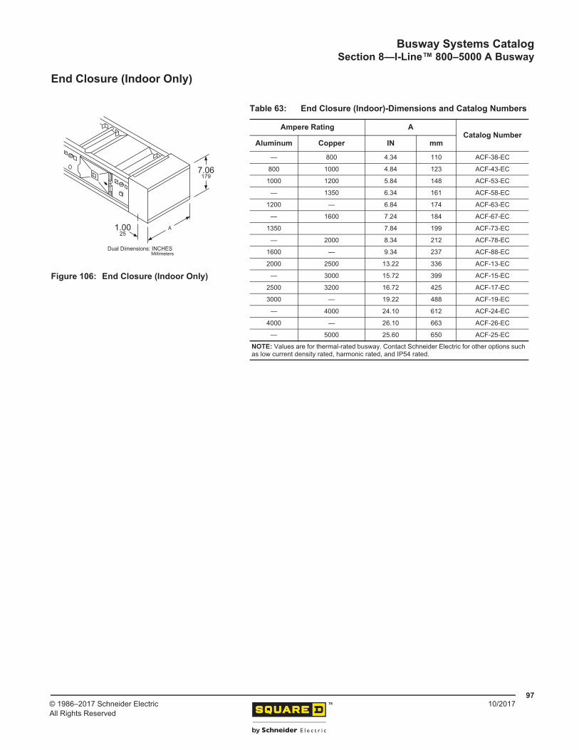
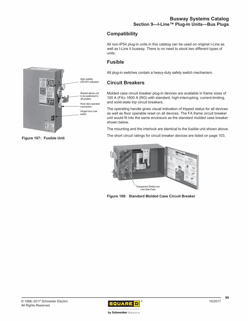
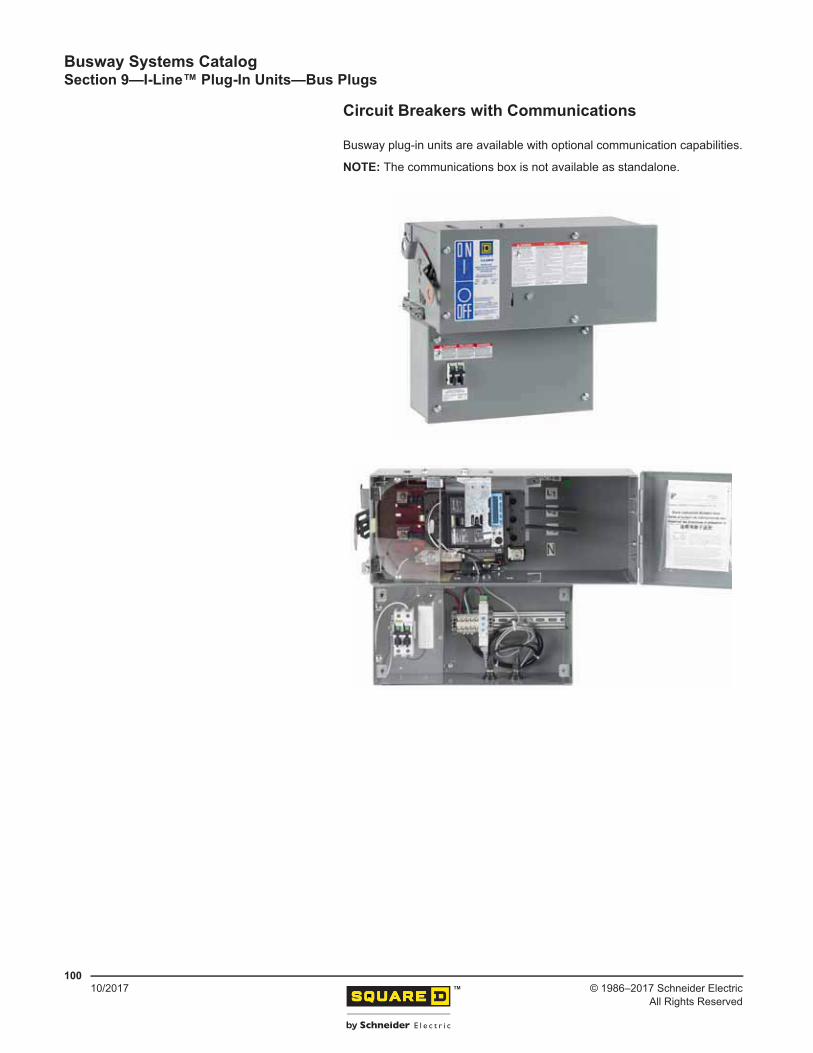
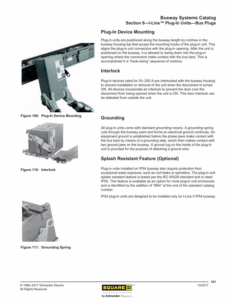
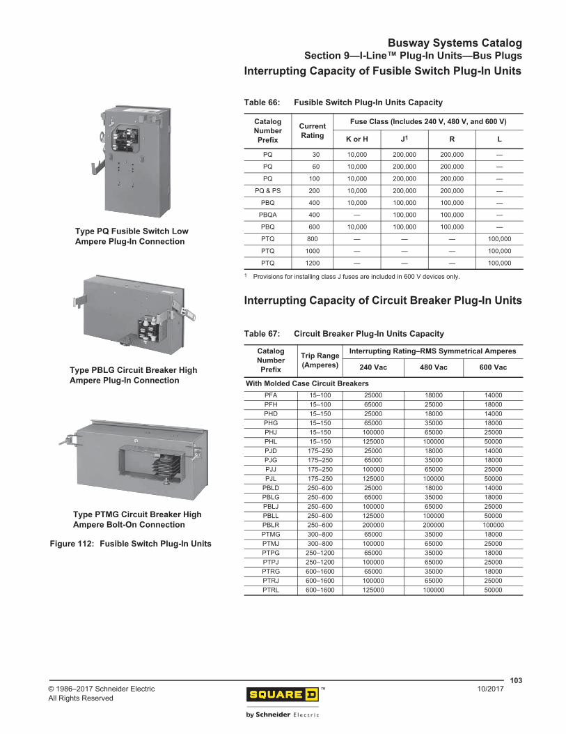
Plug-In Catalog Numbering System .............................................................................................. 98Type of Unit ................................................................................................................................... 98Compatibility .................................................................................................................................. 99Fusible ........................................................................................................................................... 99Circuit Breakers ............................................................................................................................. 99Circuit Breakers with Communications ........................................................................................ 100Plug-In Device Mounting ............................................................................................................. 101Interlock ....................................................................................................................................... 101Grounding ................................................................................................................................... 101Splash Resistant Feature (Optional) ........................................................................................... 101Special Purpose Plug-In Devices ................................................................................................ 102Interrupting Capacity of Fusible Switch Plug-In Units ............................................................................103Interrupting Capacity of Circuit Breaker Plug-In Units ...........................................................................103Required Clearances for Plug-In Unit Mounting .......................................................................... 104Vertical Mounting ......................................................................................................................... 105
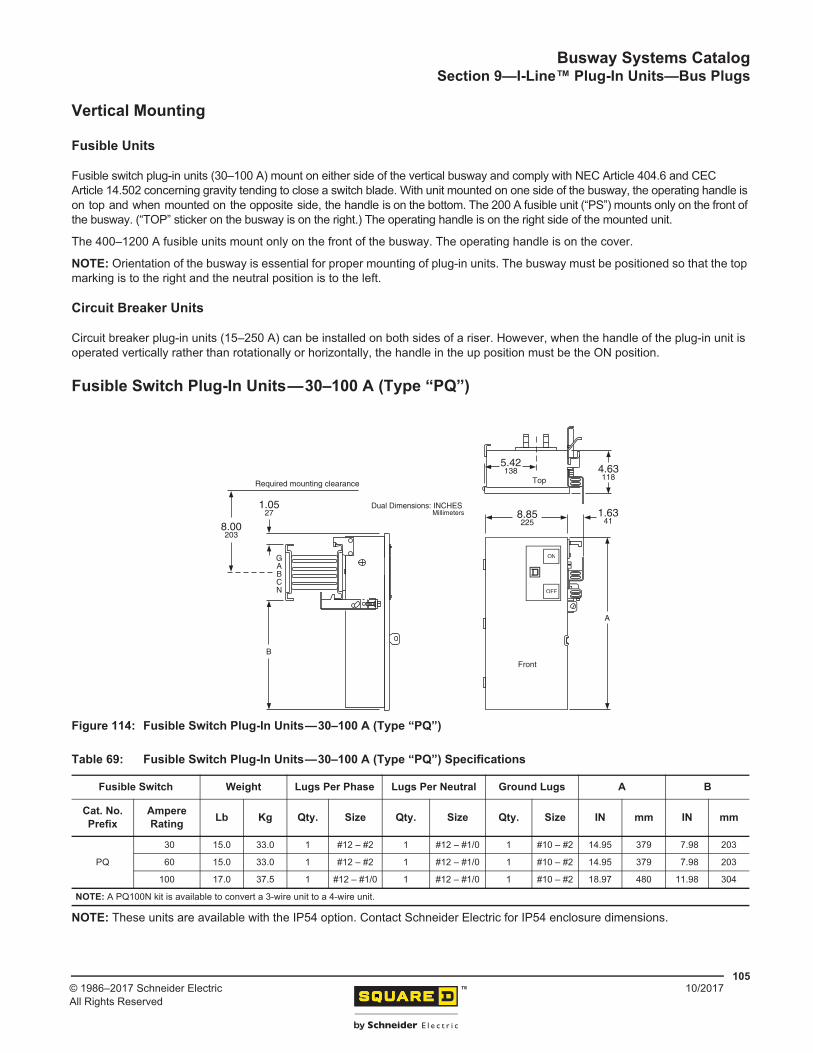
Fusible Units .......................................................................................................................... 105Circuit Breaker Units .............................................................................................................. 105
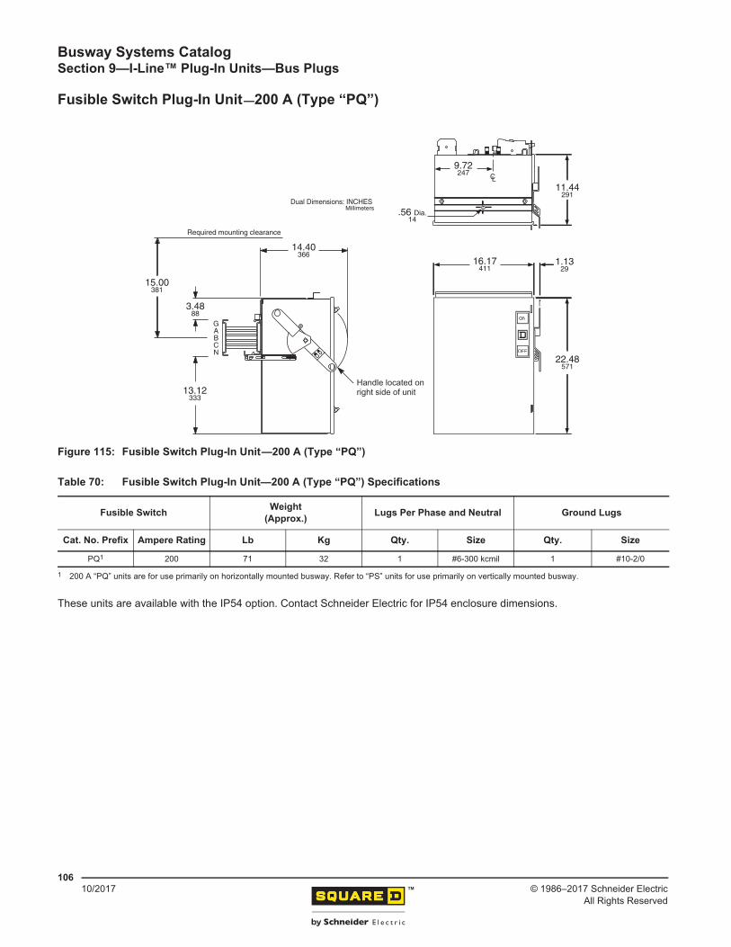
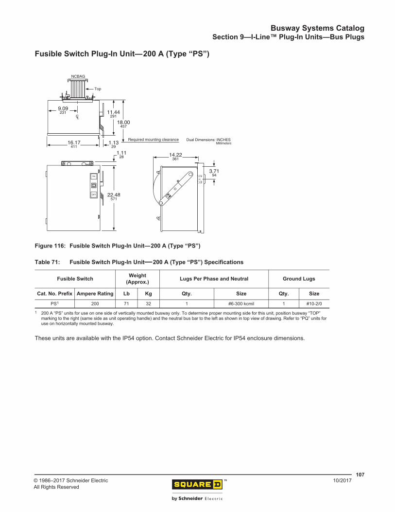
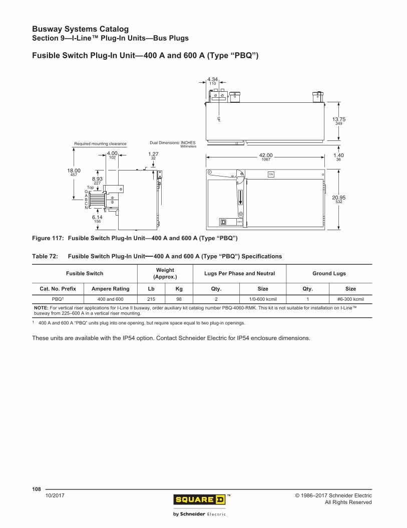
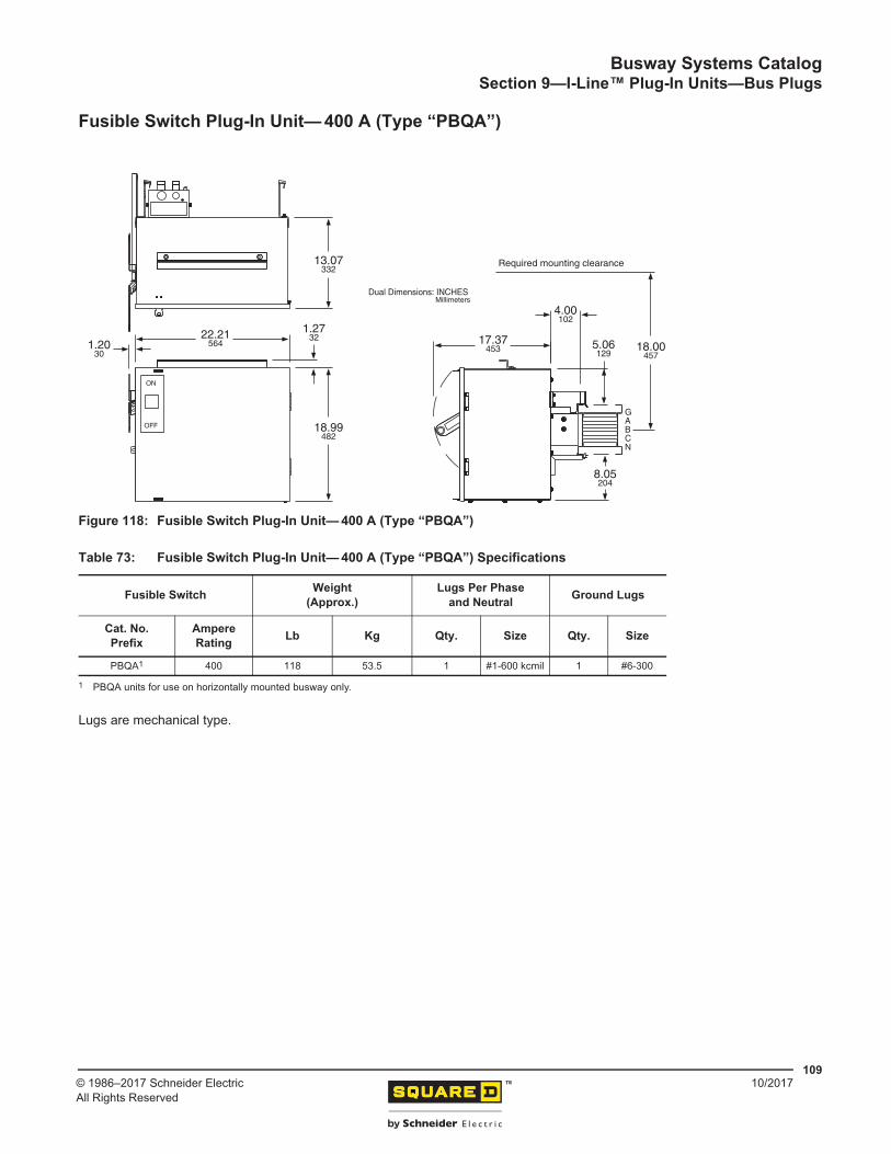
Fusible Switch Plug-In Units—30–100 A (Type “PQ”) ................................................................ 105Fusible Switch Plug-In Unit—200 A (Type “PQ”) ........................................................................ 106Fusible Switch Plug-In Unit—200 A (Type “PS”) ........................................................................ 107Fusible Switch Plug-In Unit—400 A and 600 A (Type “PBQ”) .................................................... 108Fusible Switch Plug-In Unit— 400 A (Type “PBQA”) ................................................................... 109
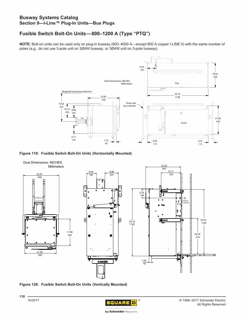
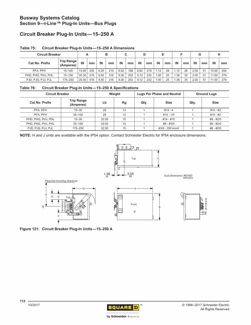
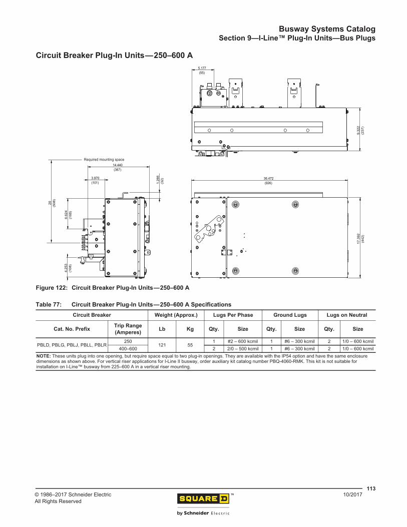
Fusible Switch Bolt-On Units—800–1200 A (Type “PTQ”) ......................................................... 110Circuit Breaker Plug-In Units—15–250 A .................................................................................... 112Circuit Breaker Plug-In Units—250–600 A .................................................................................. 113Circuit Breaker Plug-In Units with Micrologic™ Electronic Trip Units and Communication ......... 114
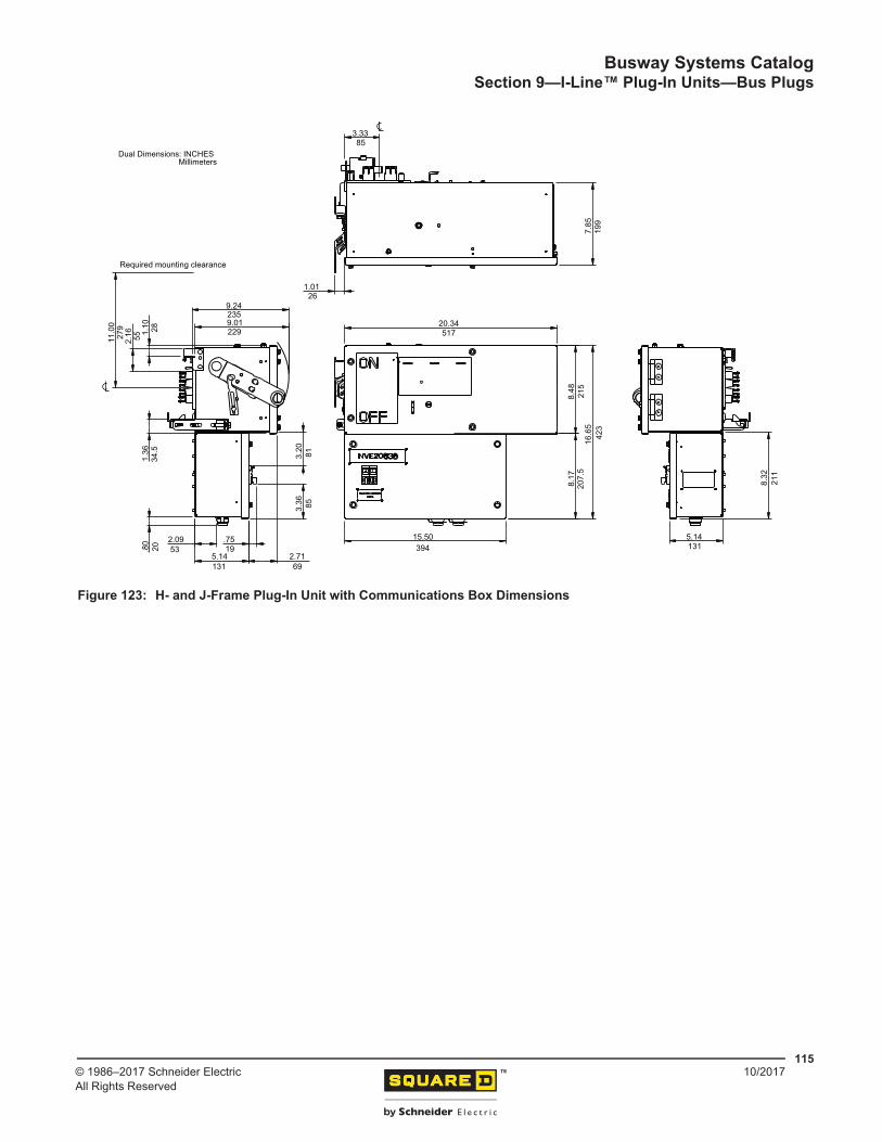
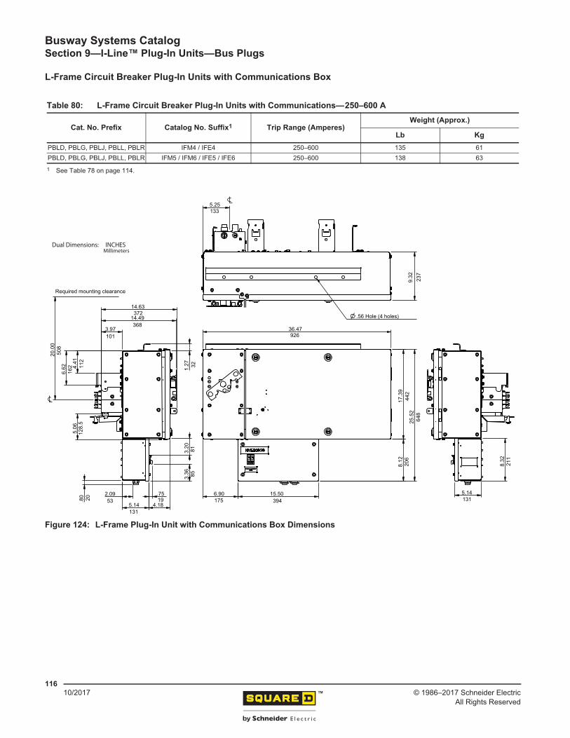
H-and J-Frame Circuit Breaker Plug-In Units with Communications Box .............................. 114L-Frame Circuit Breaker Plug-In Units with Communications Box ......................................... 116
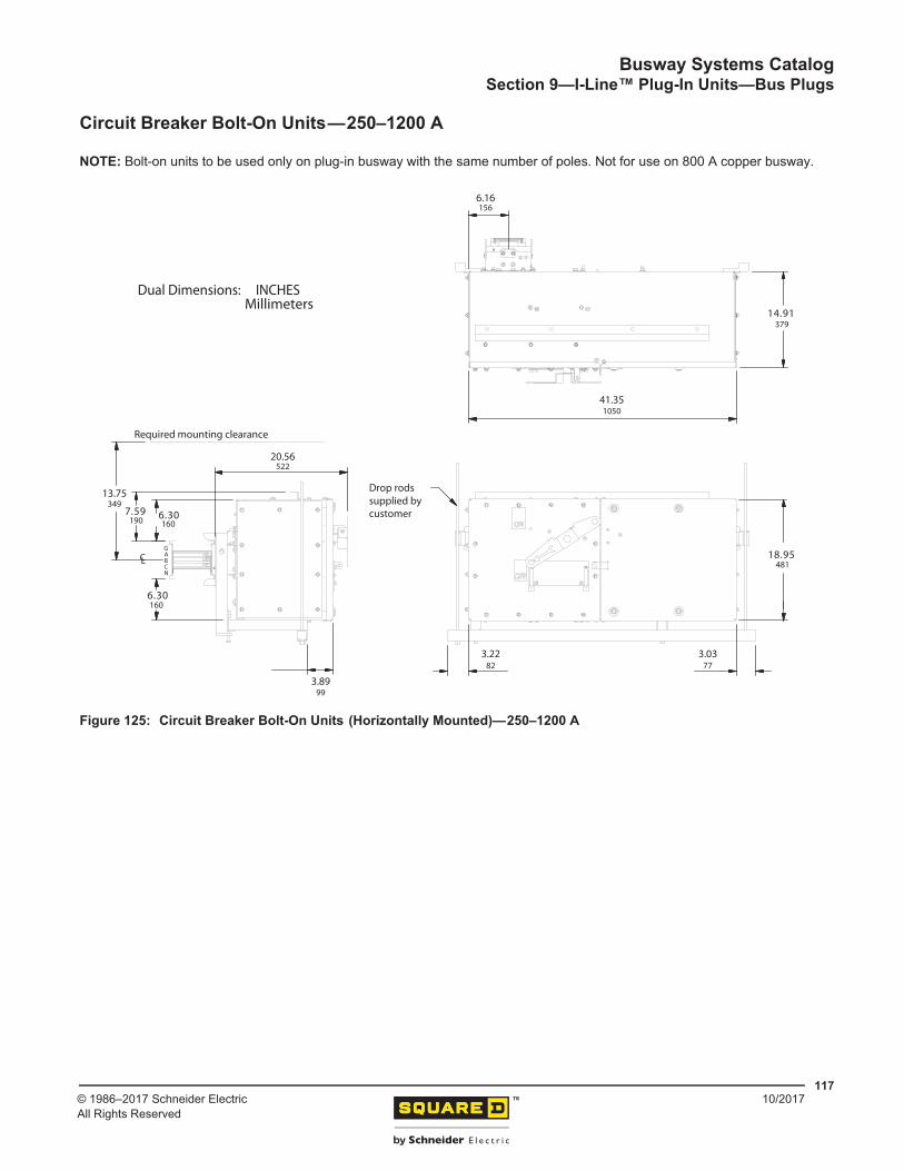
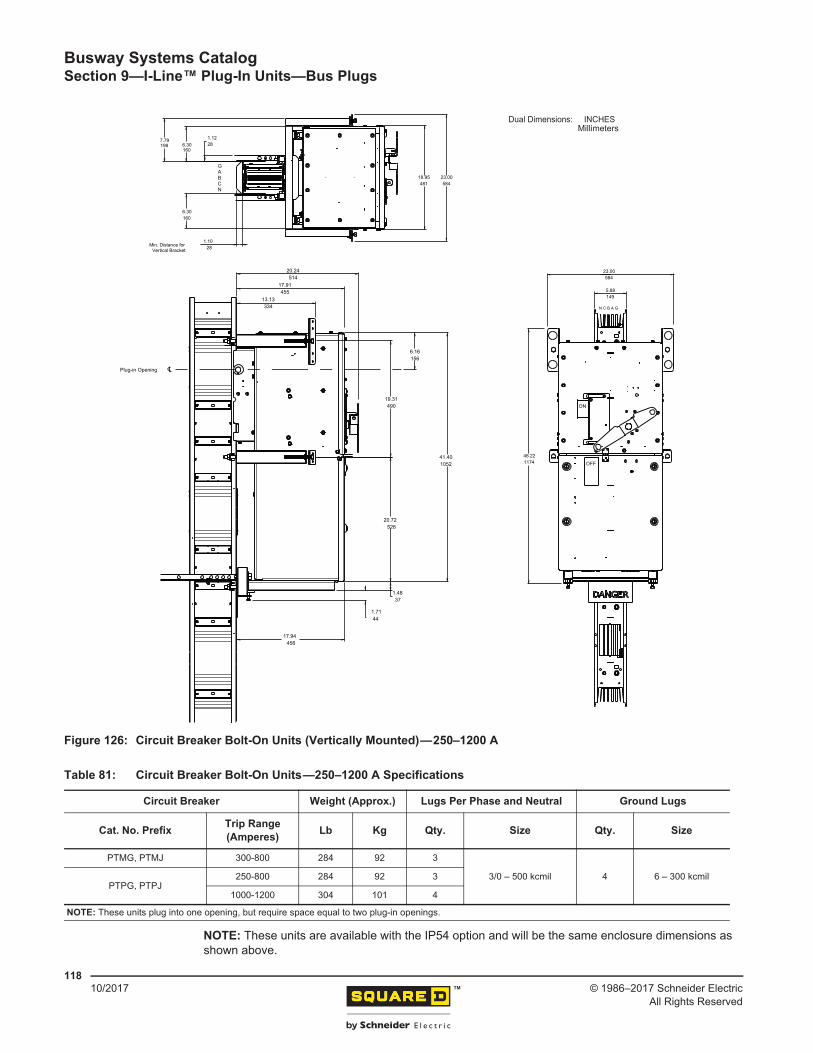
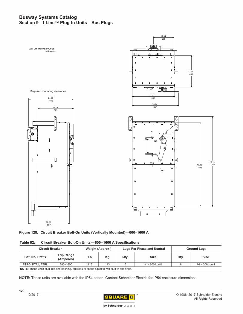
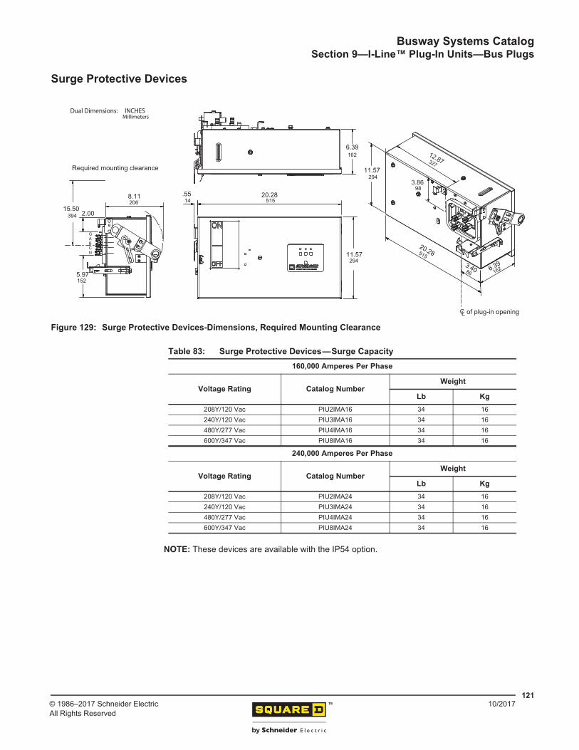
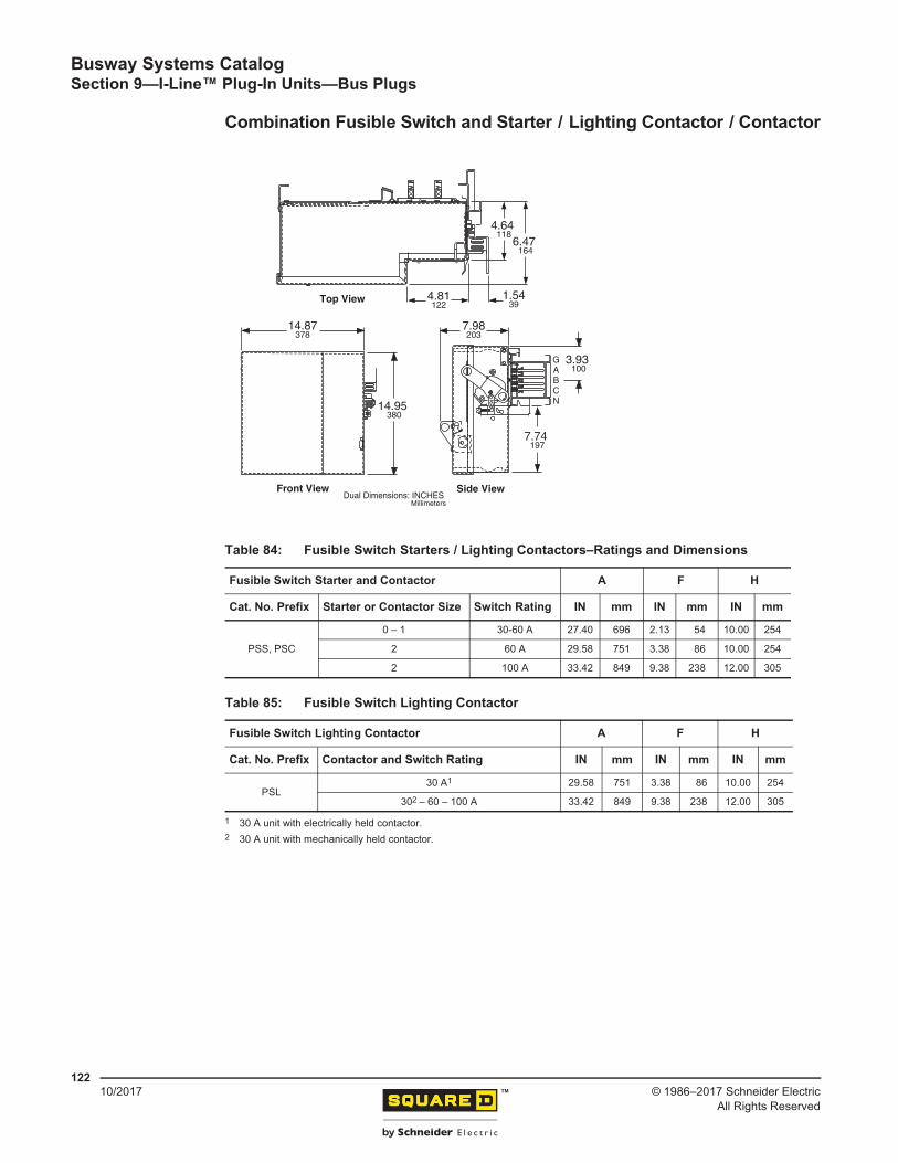
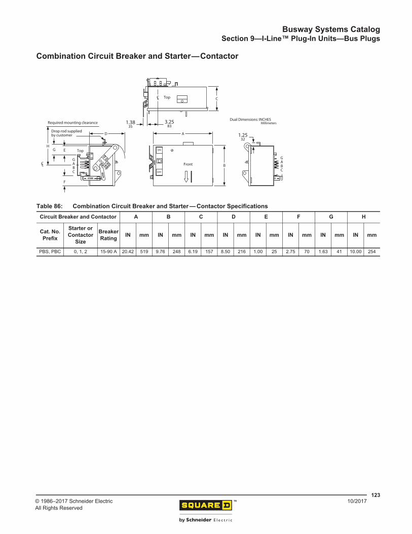
Circuit Breaker Bolt-On Units—250–1200 A ............................................................................... 117Circuit Breaker Bolt-On Units—600–1600 A ............................................................................... 119Surge Protective Devices ............................................................................................................ 121Combination Fusible Switch and Starter / Lighting Contactor / Contactor ...................................... 122Combination Circuit Breaker and Starter—Contactor ................................................................. 123Ground Detector and Neutralizer ................................................................................................. 124
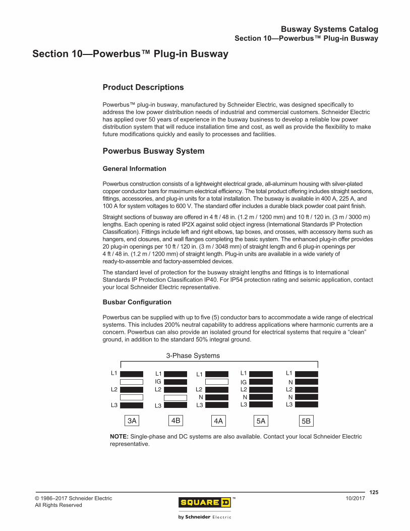
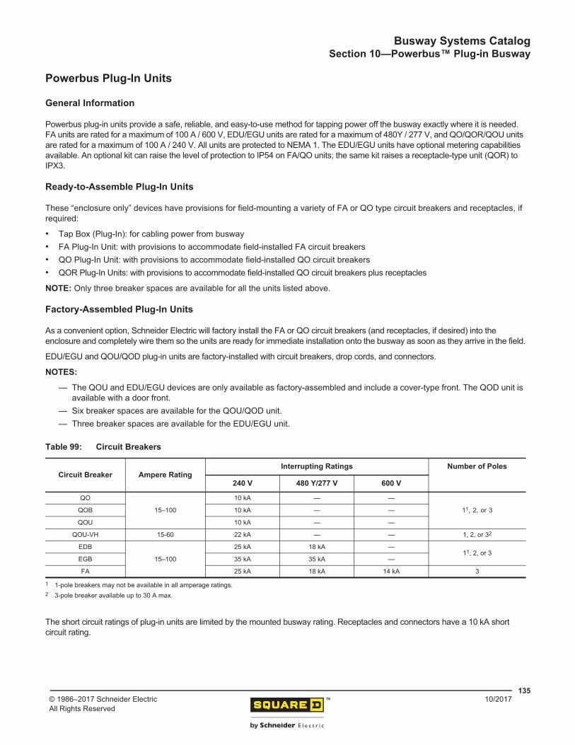
Product Descriptions ................................................................................................................... 125Powerbus Busway System .......................................................................................................... 125
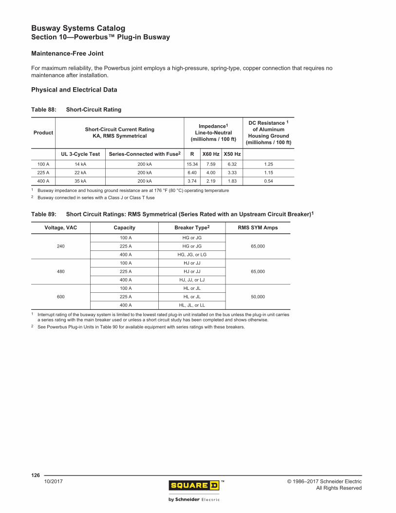
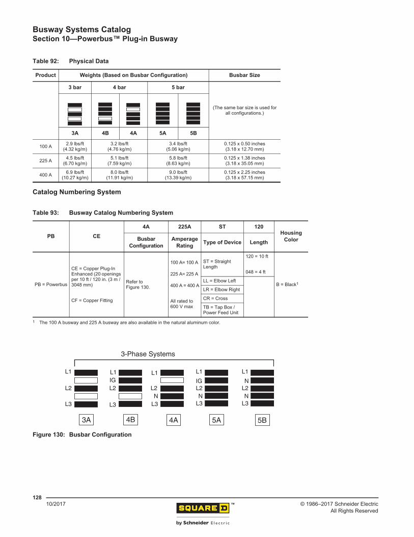
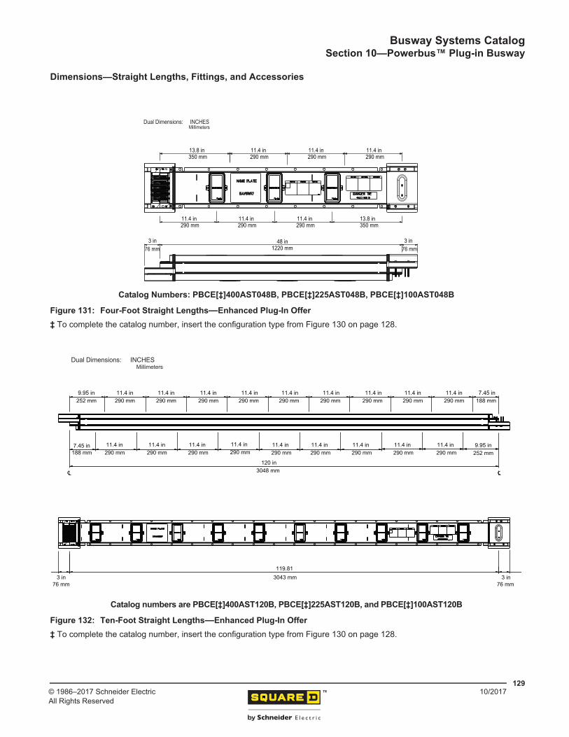
General Information ............................................................................................................... 125Busbar Configuration ............................................................................................................. 125Maintenance-Free Joint ......................................................................................................... 126Physical and Electrical Data ..................................................................................................126Catalog Numbering System ................................................................................................... 128Dimensions—Straight Lengths, Fittings, and Accessories .................................................... 129
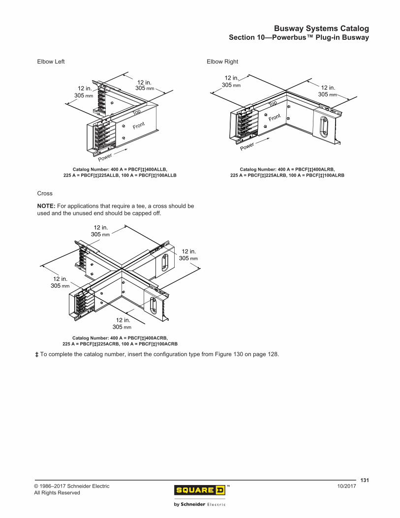
Joint Detail ....................................................................................................................... 130Cross Sections ................................................................................................................. 130Elbow Left ........................................................................................................................ 131Elbow Right ...................................................................................................................... 131Cross................................................................................................................................ 131......................................................................................................................................... 131
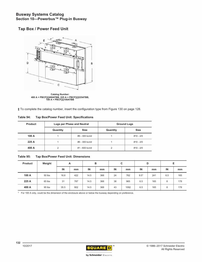
Tap Box / Power Feed Unit ......................................................................................................... 132......................................................................................................................................... 132
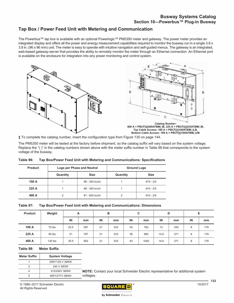
Tap Box / Power Feed Unit with Metering and Communication .................................................. 133Powerbus Plug-In Units ............................................................................................................... 135
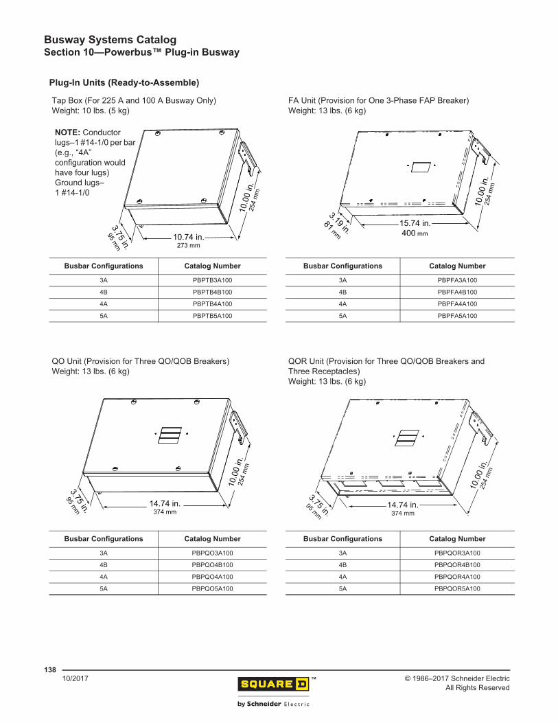
General Information ............................................................................................................... 135Ready-to-Assemble Plug-In Units .......................................................................................... 135Factory-Assembled Plug-In Units .......................................................................................... 135Catalog Numbering System ................................................................................................... 136Plug-In Units (Ready-to-Assemble) ....................................................................................... 138Plug-In Units (Factory-Assembled) ........................................................................................ 139
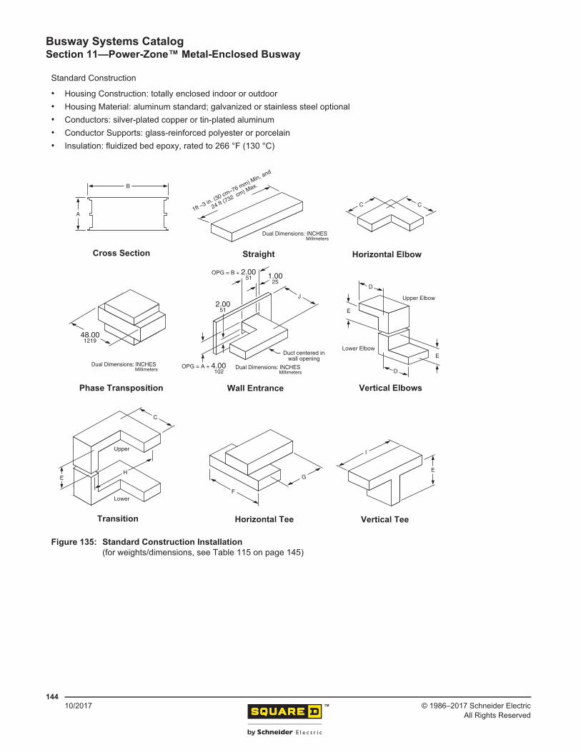
General ........................................................................................................................................ 143Power-Zone™ Bus Standard Construction ............................................................................ 147
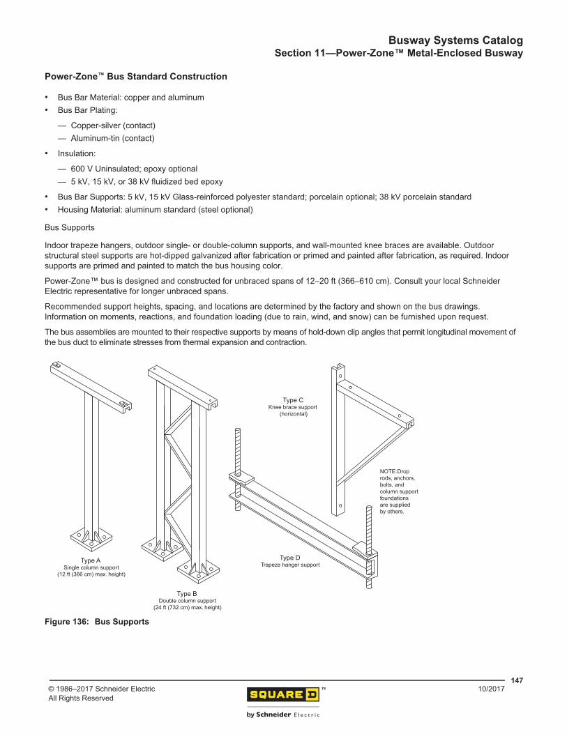
Bus Supports.................................................................................................................... 147Layout and Instructions .......................................................................................................... 148
General Layout Instruction .................................................................................................... 149Bus Footage..................................................................................................................... 149Weatherproof Bus ............................................................................................................ 149
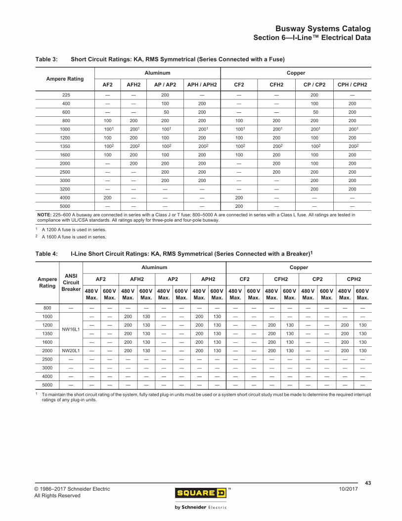
Table 1: Short Circuit Ratings: UL 3-Cycle Test (kA, RMS Symmetrical) ..................... 42Table 2: Short Circuit Ratings: 6-Cycle and 30-Cycle Tests (kA, RMS Symmetrical) .. 42Table 3: Short Circuit Ratings: KA, RMS Symmetrical (Series Connected with a Fuse) . 43Table 4: I-Line Short Circuit Ratings: KA, RMS Symmetrical (Series Connected
with a Breaker)................................................................................................ 43Table 5: Line-to-Neutral (Milliohms Per 100 Feet) ........................................................ 44Table 6: Resistance Values for Aluminum Integral Ground Bus................................... 44Table 7: Power Factor–Average Phase Line-To-Line Voltage Drop in Volts Per
100 ft (3048 cm).............................................................................................. 45Table 8: Aluminum Busway–Average Phase Line-to-Line Voltage Drop in Volts Per
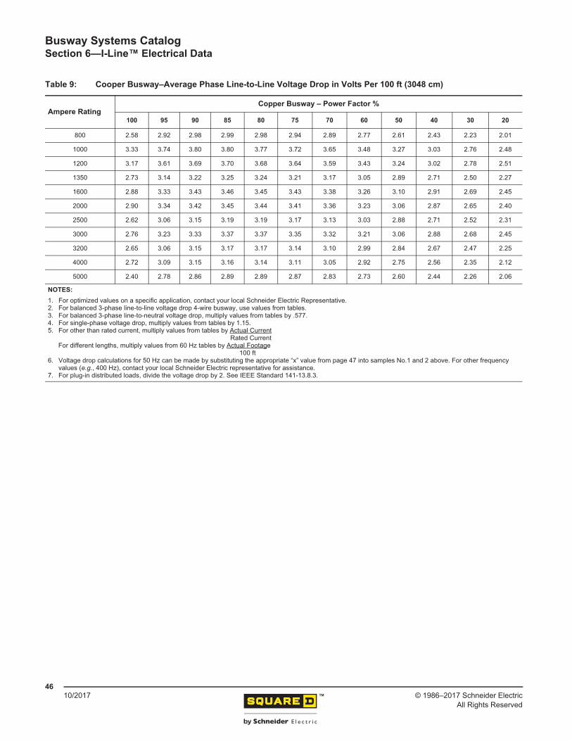
100 ft (3048 cm).............................................................................................. 45Table 9: Cooper Busway–Average Phase Line-to-Line Voltage Drop in Volts Per
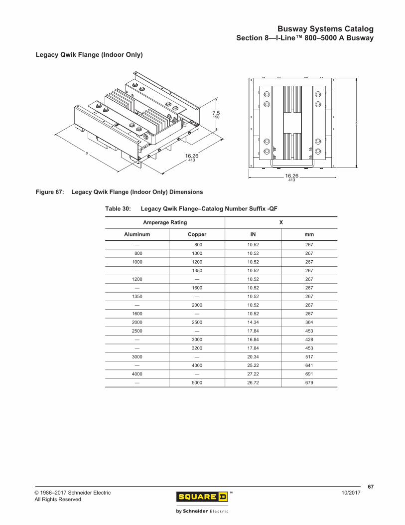
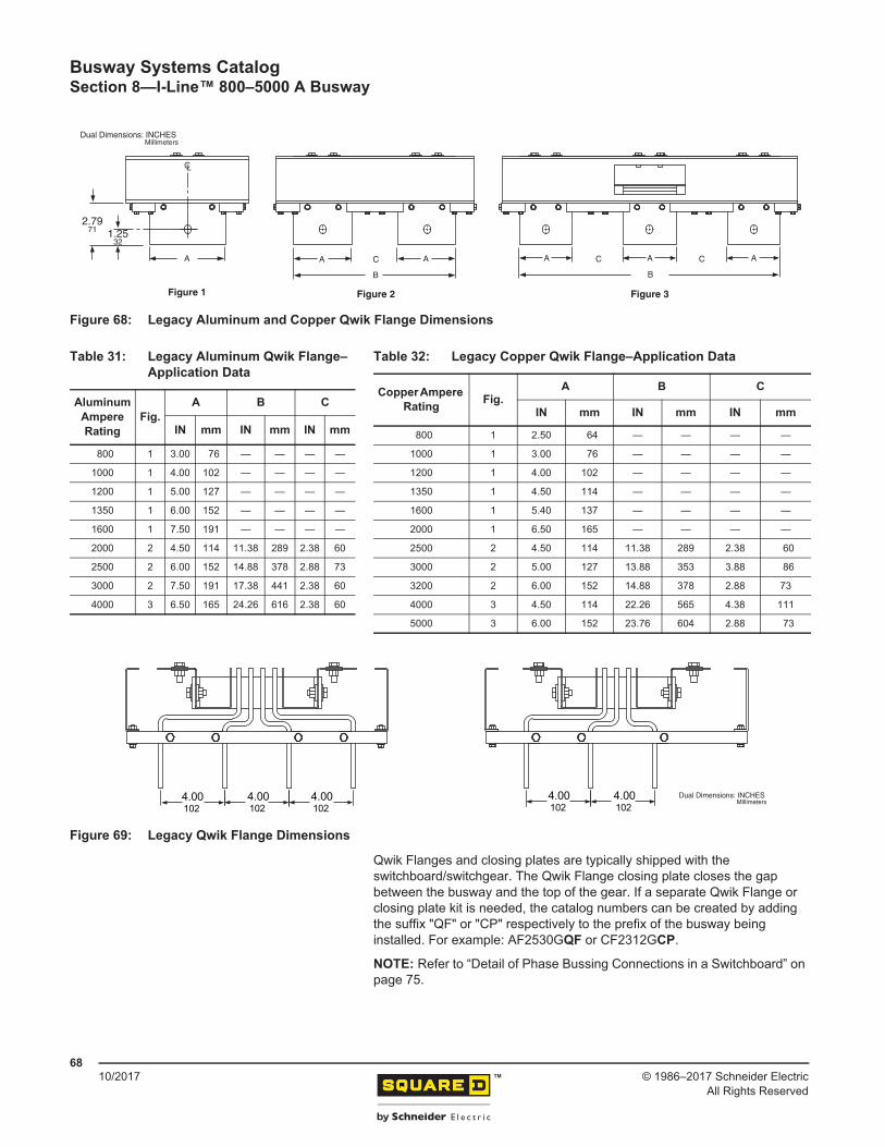
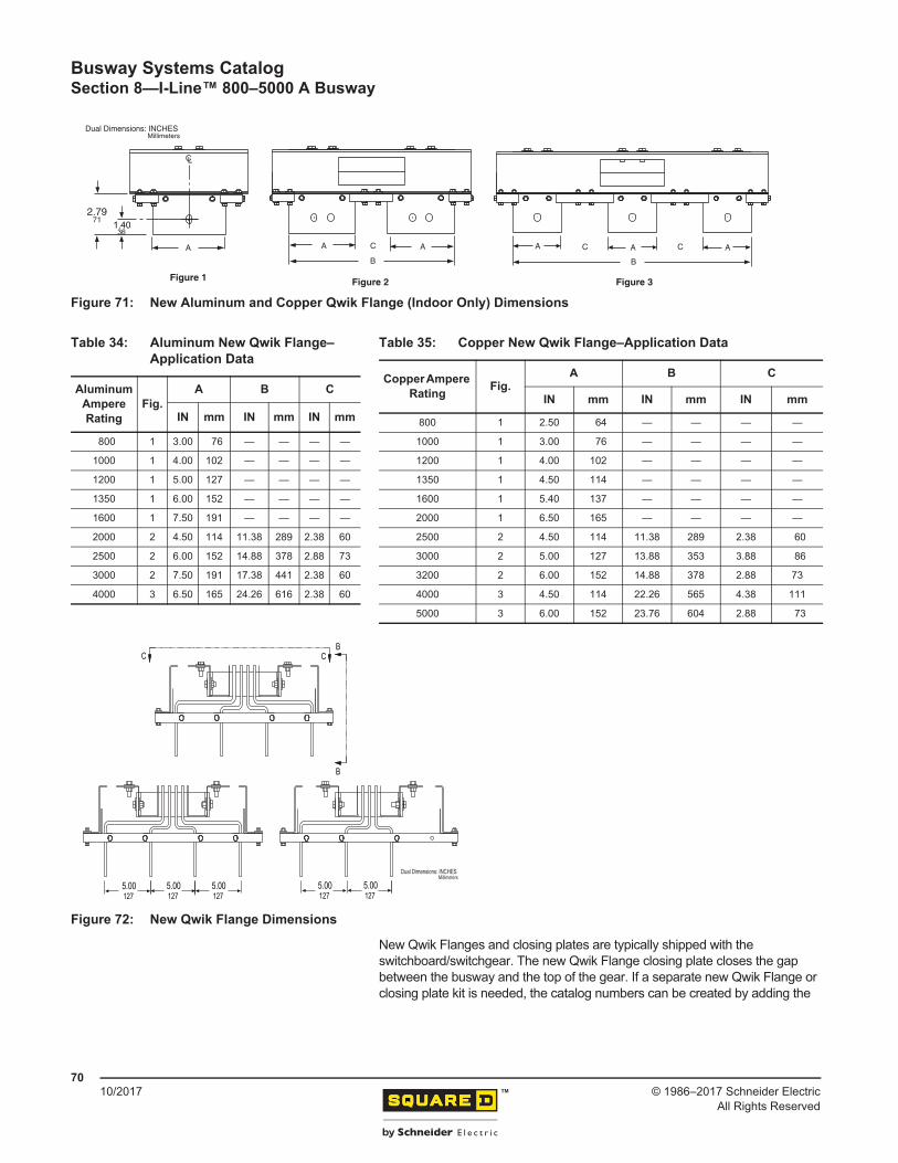
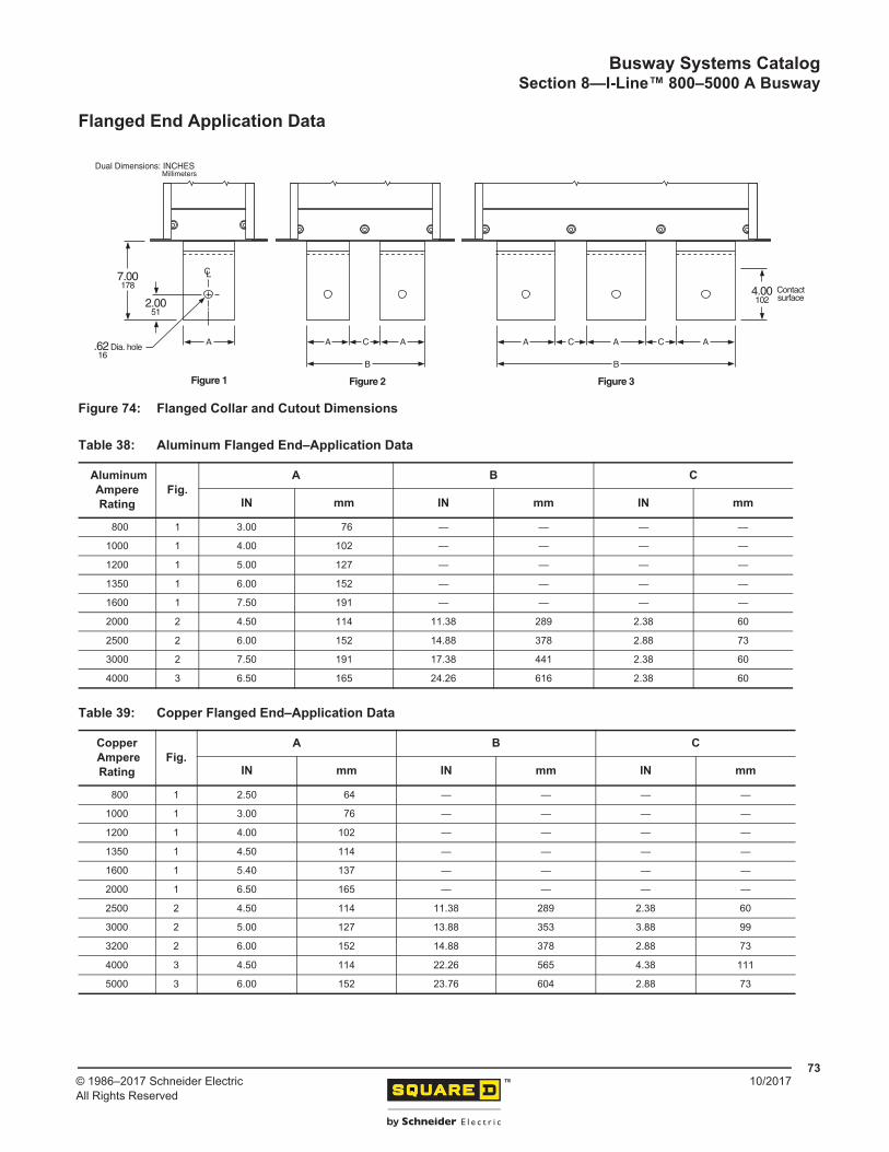
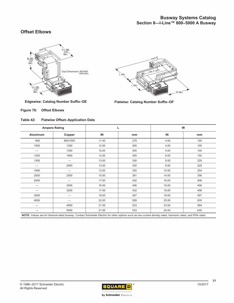
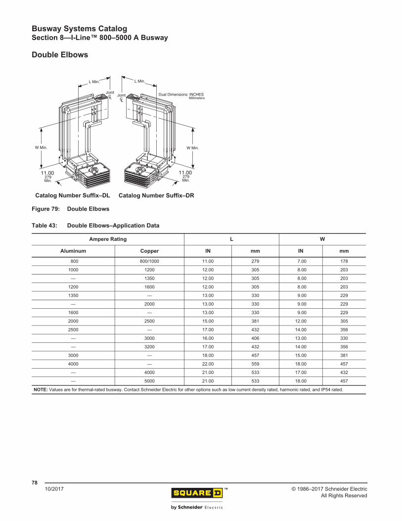
100 ft (3048 cm).............................................................................................. 46Table 10: Cross-Section–Aluminum Content and Weight............................................... 49Table 11: Cross-Section–Copper Content and Weight................................................... 49Table 12: Cable Tap Boxes (Plug-In)—Dimensions and Other Specifications ............... 50Table 13: Cable Tap Boxes (End)—Dimensions and Other Specifications .................... 51Table 14: Tees–Application Data.................................................................................... 52Table 15: Expansion Fitting–Application Data ................................................................ 53Table 16: Unfused Reducer–Catalog Number Suffix...................................................... 53Table 17: Flanged End–Cutout Dimensions ................................................................... 54Table 18: Flanged End–Dimensions............................................................................... 54Table 19: Hanger (Horizontal Flatwise)–Application Data .............................................. 55Table 20: Hanger (Horizontal Edgewise)–Application Data............................................ 55Table 21: Hanger (Vertical Fixed)-–Dimensions and Catalog Numbers ......................... 57Table 22: Hanger (Vertical Spring)-–Dimensions and Catalog Numbers ....................... 58Table 23: Seismic Hanger—Dimensions ........................................................................ 59Table 24: End Closure–Dimensions and Catalog Number ............................................. 60Table 25: Wall and Floor Flange–Application Data......................................................... 60Table 26: Measurements of Required Wall and Floor Openings .................................... 61Table 27: Cross-Sections–Aluminum Content and Weight............................................. 63Table 28: Cross-Sections–Copper Content and Weight ................................................. 64Table 29: Straight Lengths—Catalog No. Suffix ............................................................. 65Table 30: Legacy Qwik Flange–Catalog Number Suffix -QF .......................................... 67Table 31: Legacy Aluminum Qwik Flange–Application Data .......................................... 68Table 32: Legacy Copper Qwik Flange–Application Data .............................................. 68Table 33: New Qwik Flange–Catalog Number Suffix -NQF............................................ 69Table 34: Aluminum New Qwik Flange–Application Data............................................... 70Table 35: Copper New Qwik Flange–Application Data................................................... 70Table 36: Flanged Collar Hole Location and Spacing..................................................... 71Table 37: Flanged Collar and Cutout Dimensions .......................................................... 72Table 38: Aluminum Flanged End–Application Data ...................................................... 73Table 39: Copper Flanged End–Application Data........................................................... 73Table 40: Flanged End-Flanged Collar Hole Location and Spacing ............................... 74Table 41: Flatwise Elbows–Application Data .................................................................. 76Table 42: Flatwise Offset–Application Data .................................................................... 77Table 43: Double Elbows–Application Data.................................................................... 78Table 44: Indoor Cable Tap Box (End)–Application Data ............................................... 79Table 45: Outdoor Cable Tap Box (End)–Application Data ............................................ 80Table 46: Cable Tap Box (Center)–Dimensions and Lug Specifications ........................ 81
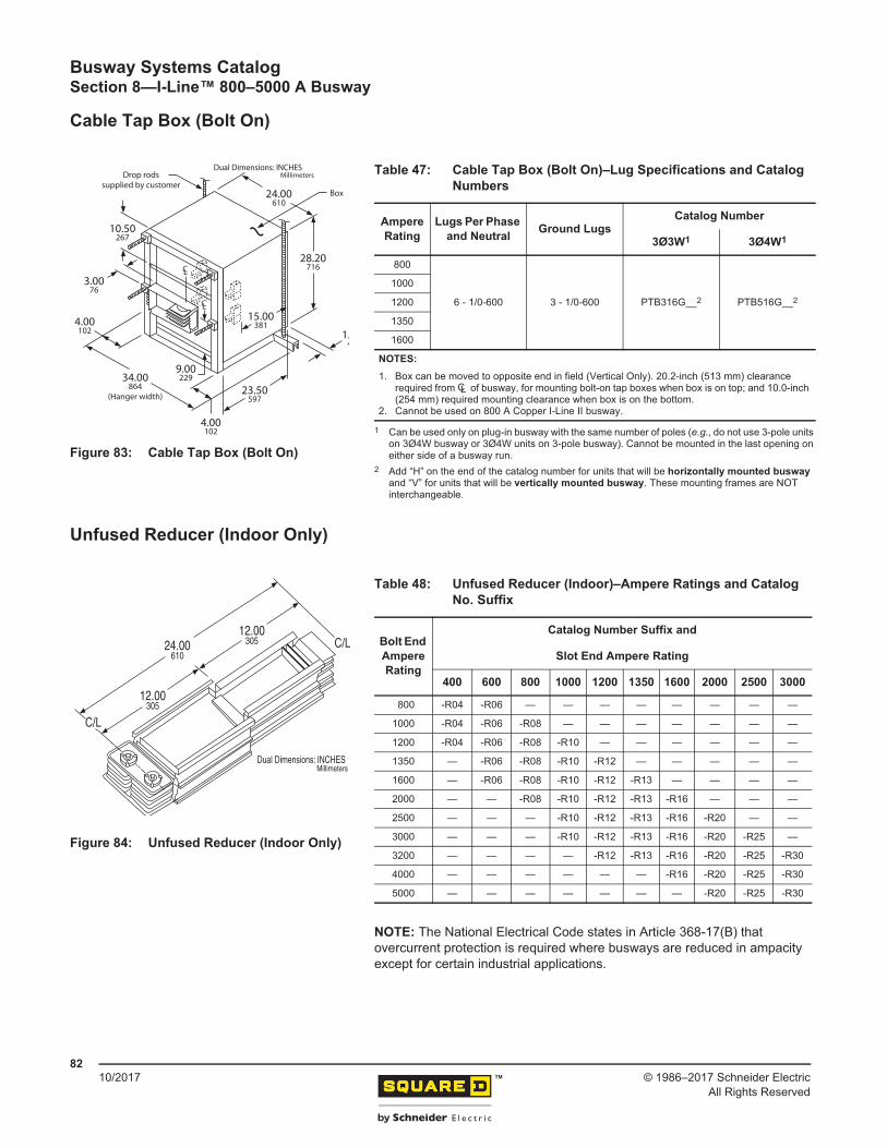
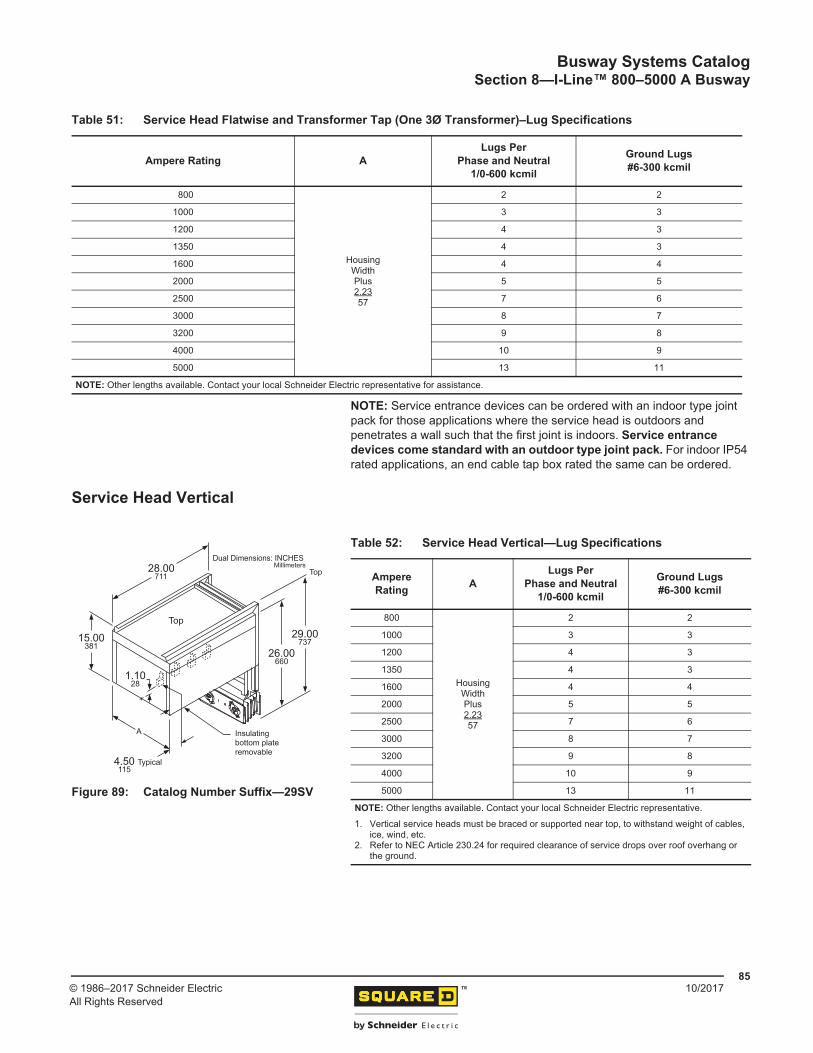
Table 47: Cable Tap Box (Bolt On)–Lug Specifications and Catalog Numbers.............. 82Table 48: Unfused Reducer (Indoor)–Ampere Ratings and Catalog No. Suffix.............. 82Table 49: Expansion Fitting (Indoor) ............................................................................... 83Table 50: Tees—Dimensions and Catalog No. Suffix..................................................... 83Table 51: Service Head Flatwise and Transformer Tap (One 3Ø Transformer)–Lug
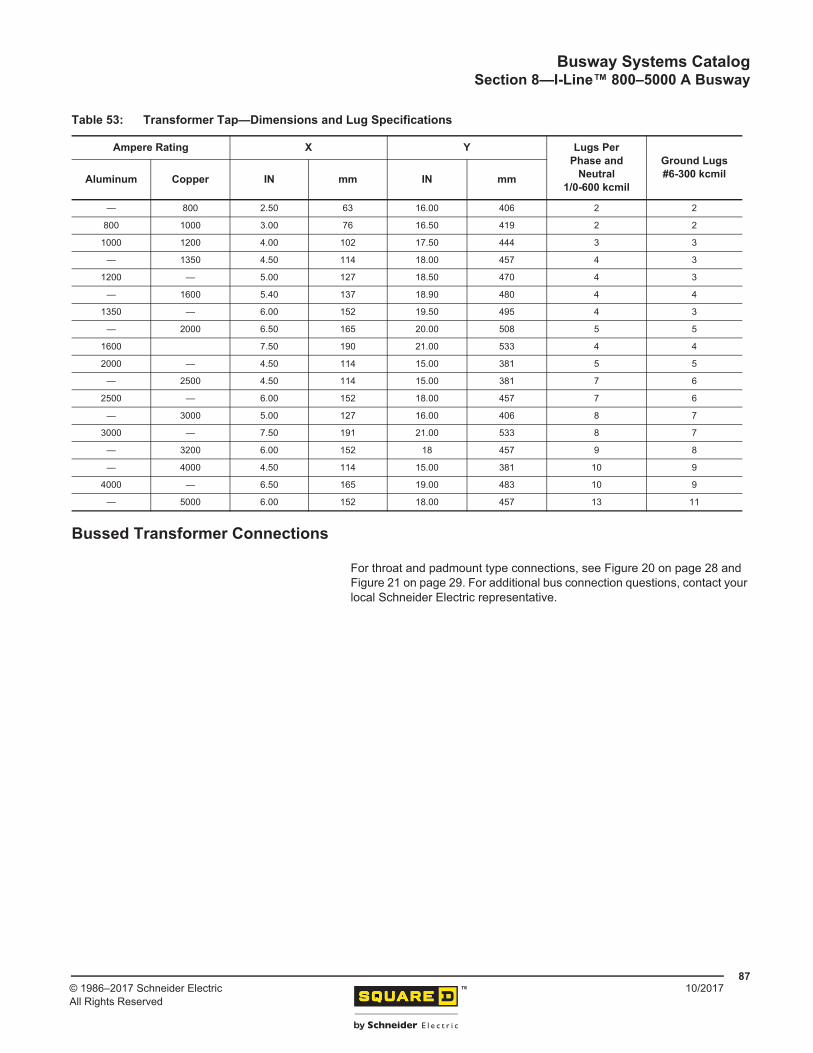
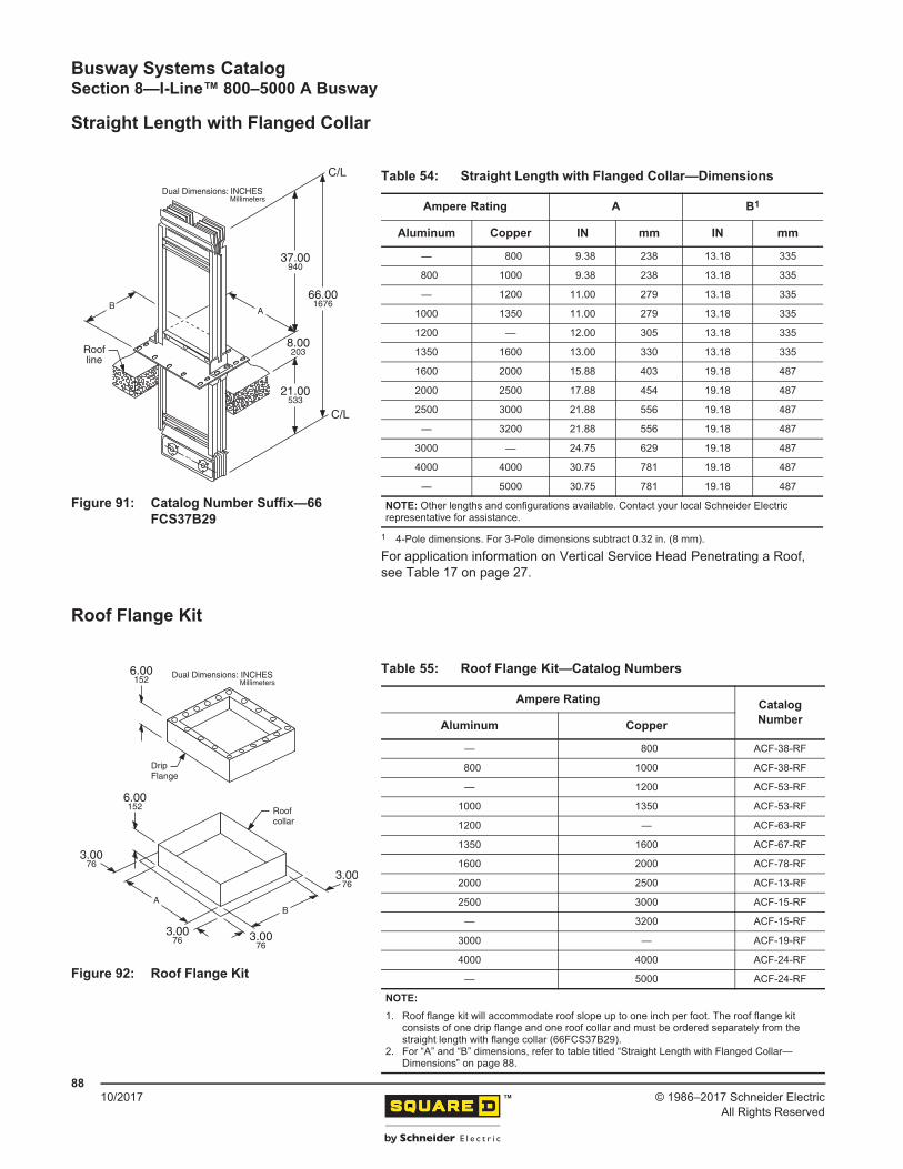
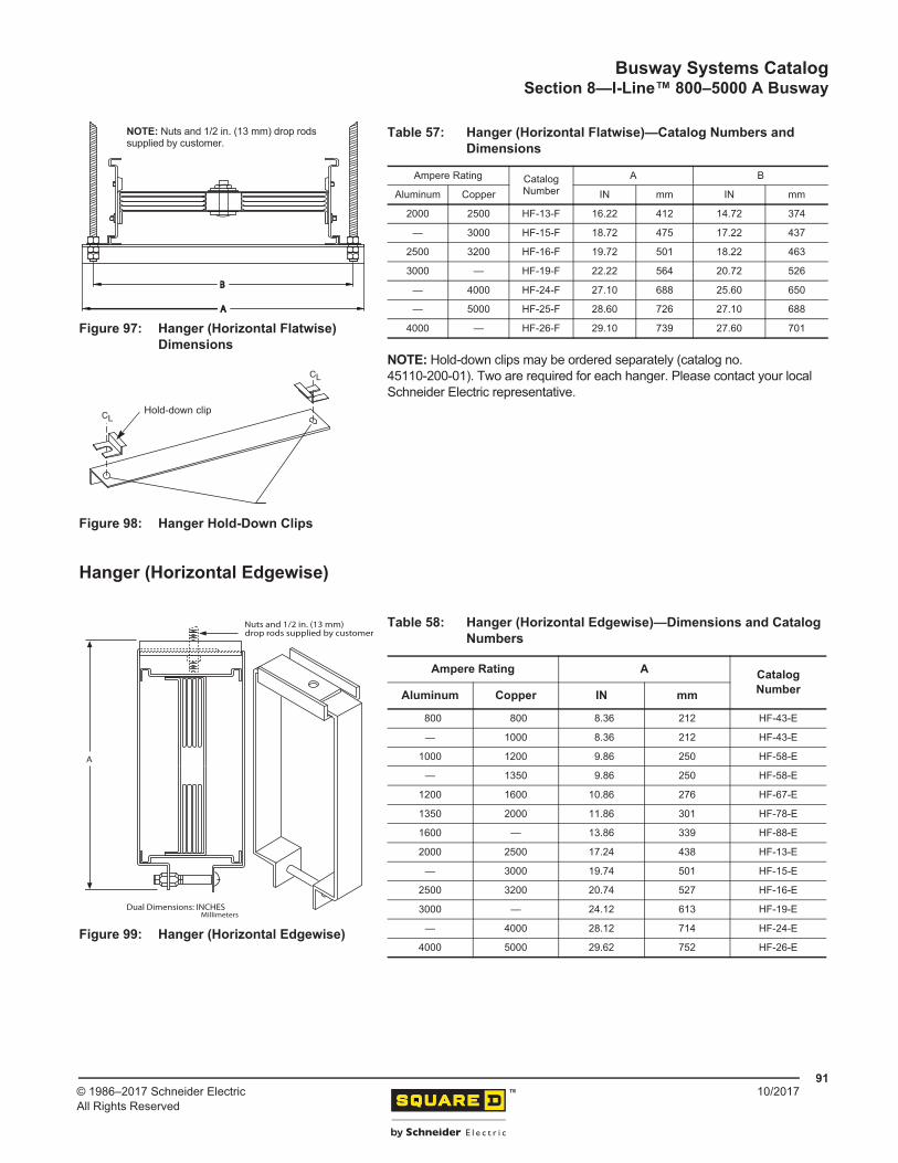
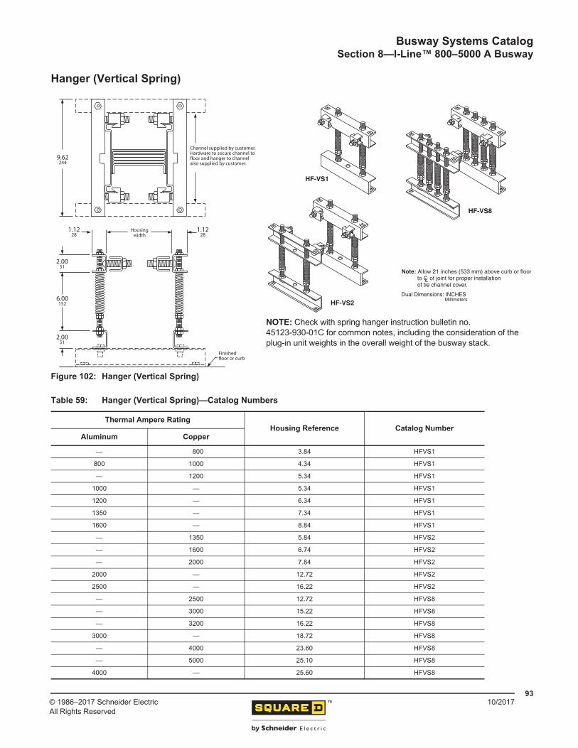
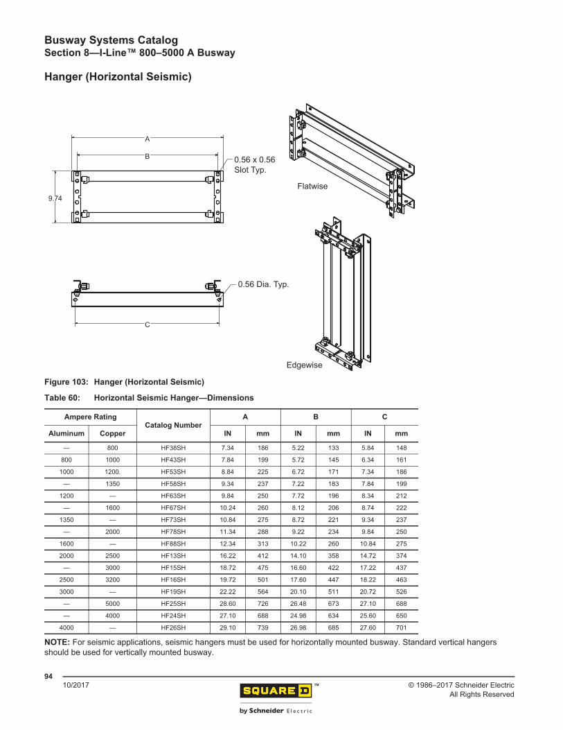
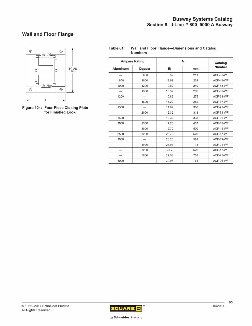
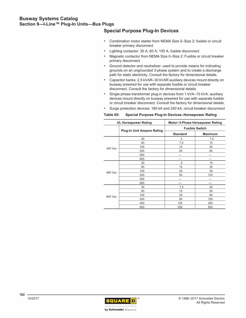
Specifications.................................................................................................. 85Table 52: Service Head Vertical—Lug Specifications..................................................... 85Table 53: Transformer Tap—Dimensions and Lug Specifications.................................. 87Table 54: Straight Length with Flanged Collar—Dimensions ......................................... 88Table 55: Roof Flange Kit—Catalog Numbers................................................................ 88Table 56: Hanger (Horizontal Flatwise)—Catalog Numbers........................................... 90Table 57: Hanger (Horizontal Flatwise)—Catalog Numbers and Dimensions ................ 91Table 58: Hanger (Horizontal Edgewise)—Dimensions and Catalog Numbers.............. 91Table 59: Hanger (Vertical Spring)—Catalog Numbers.................................................. 93Table 60: Horizontal Seismic Hanger—Dimensions ....................................................... 94Table 61: Wall and Floor Flange—Dimensions and Catalog Numbers .......................... 95Table 62: Wall and Floor Required Cut-Outs—Dimensions ........................................... 96Table 63: End Closure (Indoor)-Dimensions and Catalog Numbers............................... 97Table 64: Maximum Amperage for Unit Types ............................................................... 98Table 65: Special Purpose Plug-In Devices–Horsepower Rating................................. 102Table 66: Fusible Switch Plug-In Units Capacity .......................................................... 103Table 67: Circuit Breaker Plug-In Units Capacity.......................................................... 103Table 68: Required Clearances for Plug-In Unit Mounting ........................................... 104Table 69: Fusible Switch Plug-In Units—30–100 A (Type “PQ”) Specifications .......... 105Table 70: Fusible Switch Plug-In Unit—200 A (Type “PQ”) Specifications................... 106Table 71: Fusible Switch Plug-In Unit—200 A (Type “PS”) Specifications ................... 107Table 72: Fusible Switch Plug-In Unit—400 A and 600 A (Type “PBQ”) Specifications 108Table 73: Fusible Switch Plug-In Unit— 400 A (Type “PBQA”) Specifications ............. 109Table 74: Fusible Switch Bolt-On Units — 800–1200 A (Type “PTQ”) Specifications... 111Table 75: Circuit Breaker Plug-In Units—15–250 A Dimensions ................................. 112Table 76: Circuit Breaker Plug-In Units—15–250 A Specifications.............................. 112Table 77: Circuit Breaker Plug-In Units—250–600 A Specifications............................ 113Table 78: Communication Suffix ................................................................................... 114Table 79: H-and J-Frame Circuit Breaker Plug-In Units with Communications—60–250 A 114Table 80: L-Frame Circuit Breaker Plug-In Units with Communications—250–600 A.. 116Table 81: Circuit Breaker Bolt-On Units—250–1200 A Specifications ......................... 118Table 82: Circuit Breaker Bolt-On Units—600–1600 A Specifications ......................... 120Table 83: Surge Protective Devices—Surge Capacity................................................. 121Table 84: Fusible Switch Starters / Lighting Contactors–Ratings and Dimensions ...... 122Table 85: Fusible Switch Lighting Contactor................................................................. 122Table 86: Combination Circuit Breaker and Starter — Contactor Specifications........... 123Table 87: Ground Detector and Neutralizer—Catalog Numbers and Approximate Weights 124Table 88: Short-Circuit Rating....................................................................................... 126Table 89: Short Circuit Ratings: RMS Symmetrical (Series Rated with an Upstream
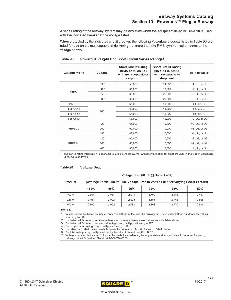
Circuit Breaker) ............................................................................................. 126Table 90: Powerbus Plug-In Unit Short Circuit Series Ratings ..................................... 127Table 91: Voltage Drop ................................................................................................. 127Table 92: Physical Data ................................................................................................ 128Table 93: Busway Catalog Numbering System ............................................................ 128Table 94: Tap Box/Power Feed Unit: Specifications..................................................... 132Table 95: Tap Box/Power Feed Unit: Dimensions ........................................................ 132Table 96: Tap Box/Power Feed Unit with Metering and Communications: Specifications.. 133Table 97: Tap Box/Power Feed Unit with Metering and Communications: Dimensions 133Table 98: Meter Suffix................................................................................................... 133
System— Devices with Receptacle / Circuit Breaker.................................... 136Table 103: Factory-Assembled Plug-In Unit Catalog Numbering System—Devices with
Drop Cords and Connectors ......................................................................... 136Table 104: Drop Cord Lengths........................................................................................ 137Table 105: Metering ........................................................................................................ 137Table 106: FA Unit with Circuit Breaker—600 V Max ..................................................... 139Table 107: QO/QOR Units with Circuit Breakers and Receptacles—120 V ................... 139Table 108: QOU Units with Circuit Breakers, Drop Cords, and Connectors (240 V Max).. 140Table 109: EDU Units with Circuit Breakers, 3 ft Drop Cords with NEMA Connectors
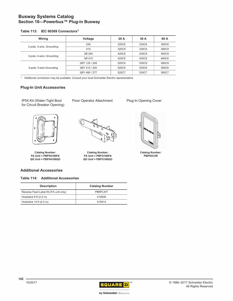
(240 V Max), and PM5350 Meter.................................................................. 140Table 112: NEMA Receptacles (R) and Connectors (C) ................................................ 141Table 110: EDU Units with Circuit Breakers, 3 ft Drop Cords with IEC Connectors
(480Y/ 277 V Max.), and PM5350 Meter........................................................... 141Table 111: Gateway Unit ................................................................................................ 141Table 113: IEC 60309 Connectors.................................................................................. 142Table 114: Additional Accessories.................................................................................. 142Table 115: Power-Zone™ Metal-Enclosed Busway—Minimum Dimensions and Other
Specifications................................................................................................ 145Table 115: Power-Zone Metal-Enclosed Busway—Minimum Dimensions and Other
Square D™ brand I-Line™ Busway, manufactured by Schneider Electric, offers a complete line of compatible, sandwich-type feeder and plug-in busway lengths and fittings. It allows maximum flexibility, and ease of installation, and offers electrical efficiency in the distribution of low voltage power for both commercial and industrial applications.
Our design and construction have been time-tested by many years of use throughout the world. I-Line busway has been used to supply power in thousands of installations throughout the world for decades. Our broad range of I-Line busway products include I-Line plug-in style from 225–600 A with aluminum or copper conductors, and I-Line II plug-in and feeder styles from 800–4000 A with aluminum conductors and up to 5000 A with copper conductors. I-Line and I-Line II busway are constructed in three-pole and four-pole full neutral configurations for system voltages to 600 V, and are rated to allow 100% of the current to flow continuously.
Busway installation is quick and easy. The compact, totally enclosed design is lightweight and easy to handle. Labor studies have shown that a 75% savings in installation time is not uncommon when comparing I-Line busway with cable and conduit installations. This significant reduction in installation time can result in total installed cost for busway being significantly lower than other distribution methods.
In addition, a wide variety of busway components and plug-in units are available for fast delivery.
No matter how you compare, I-Line busway is your solid first choice.
Sandwich Construction
I-Line feeder and plug-in busway both utilize sandwich-type construction to provide superior voltage drop characteristics, even at low power factors.
Steel housing sides and aluminum tops and bottoms have been carefully designed to reduce component weight and minimize the hysteresis and eddy current losses that are common in all-steel housings.
Plug-in busway ratings that utilize two or three bus bars per phase have a phase paralleling feature at the joint assembly of each straight length. This helps equalize bus bar loading when plugs are mounted on one side only.
The plug-in housing has notches along the top rail for easy alignment and installation of plug-in units.
Within the same ampere rating, all I-Line II busway lengths and fittings are fully compatible between feeder and plug-in styles using standard universal tie channels (housing “splice plates”) supplied with each component.
Totally Enclosed Housing
Ventilated busway depends on free air movement through a perforated housing to cool the bus bars. Unless mounted in its preferred position (for maximum bus bar cooling), ventilated busway must be de-rated. Ventilated housing also permits dirt accumulation and offers limited protection of bus bars due to the open ventilation slots.
I-Line busway has a modern “totally enclosed housing” design requiring no de-rating regardless of mounting position. Because the housing has no ventilation holes, the entry of dirt and possibility of accidental contact with bus bars is greatly reduced.
Figure 1: Ventilated Housing (left) and I-Line II Totally Enclosed Housing (right)
Busway Systems CatalogSection 1—I-Line™ Product Features
I-Line II busway is compact. The small size means it can be used in locations where feeder circuits would not otherwise be possible. Efficient use of light-weight raw materials is an additional factor in I-Line busway’s compact design.
Finish
I-Line busway users get a tough, durable, and uniform polyester powder coat paint finish, making their busway installations functional and attractive for years to come.
Insulation
UL 857 Standard for Busways requires busway systems to be designed not to exceed a total operating temperature of 203 °F (95 °C). The polyester film and epoxy insulation systems used in the high quality design of I Line II busway provides improved thermal and electrical characteristics over the UL requirements.
Plating
Bus bars for I-Line and I-Line II busway are plated to ensure low surface-to-surface contact resistance and to minimize surface corrosion. Aluminum bus bars are electroplated with a coat of tin after preparation with the ALSTAN 80 process. Copper bus bars are plated with a layer of silver that is flashed onto the surface of the bus bars.
Dielectric Testing
Underwriters Laboratories (UL) and the Canadian Standards Association (CSA) require a one-time dielectric test for all new busway designs prior to certification. This test, at two times rated voltage plus 1000 Vac (2200 Vac), is intended to confirm the integrity of the insulation system. I-Line busway passes this test.
Every length and fitting of our busway must also pass a 7500 Vdc hi-pot test before shipment from the factory. This additional test helps ensure the highest quality busway possible.
Figure 2: Compact Design
Busway Systems CatalogSection 1—I-Line™ Product Features
Visi-Tite™ One Bolt JointI-Line busway incorporates the “one bolt” joint principle. This joint design uses a high-strength (Grade 5) Visi-Tite bolt to provide a clamping force of over 4000 pounds. The force is distributed over the contact area by a pair of large diameter, spring steel, cupped conical washers. On higher ampere ratings (2000 A or above) two or three joint bolts are used—one for each set of bus bars. Our “one bolt” principle replaces older designs that required up to 32 nuts, bolts, and washers for each set of bus bars. The Visi-Tite torque indicating joint bolt is standard on all busway joints. Insulated and at ground potential, the bolt and nut are both captive to reduce installation time.
Fast, accurate torquing is a snap with Visi-Tite double-headed bolts. There’s no need for a torque wrench. Use any long-handled wrench to tighten the outer bolt head until it twists off and releases a red plastic warning disc. Any disc remaining during inspection indicates an improperly torqued joint. For maintenance of the joint or when busway is relocated, the Visi-Tite bolt should be tightened to 70 lb-ft +/- 10 lb-ft (94.92 N•m +/- 13.56 N•m) with a torque wrench.
EZ Joint Pak™ Connector Assembly
I-Line II busway offers an improved single-bolt joint package that can be removed and replaced with an isolation joint pak to electrically isolate busway sections for load shifting and maintenance. It can also be relocated to the opposite end of a length to take care of last minute job changes. The EZ Joint Pak Connector Assembly is shipped pre-assembled with each I-Line II busway length or fitting, providing minimum job site installation labor. The Visi-Tite bolt is a standard feature on all assemblies.
Figure 3: Visi-Tite Bolt
Figure 4: EZ Joint Pak Connector Assembly
Busway Systems CatalogSection 1—I-Line™ Product Features
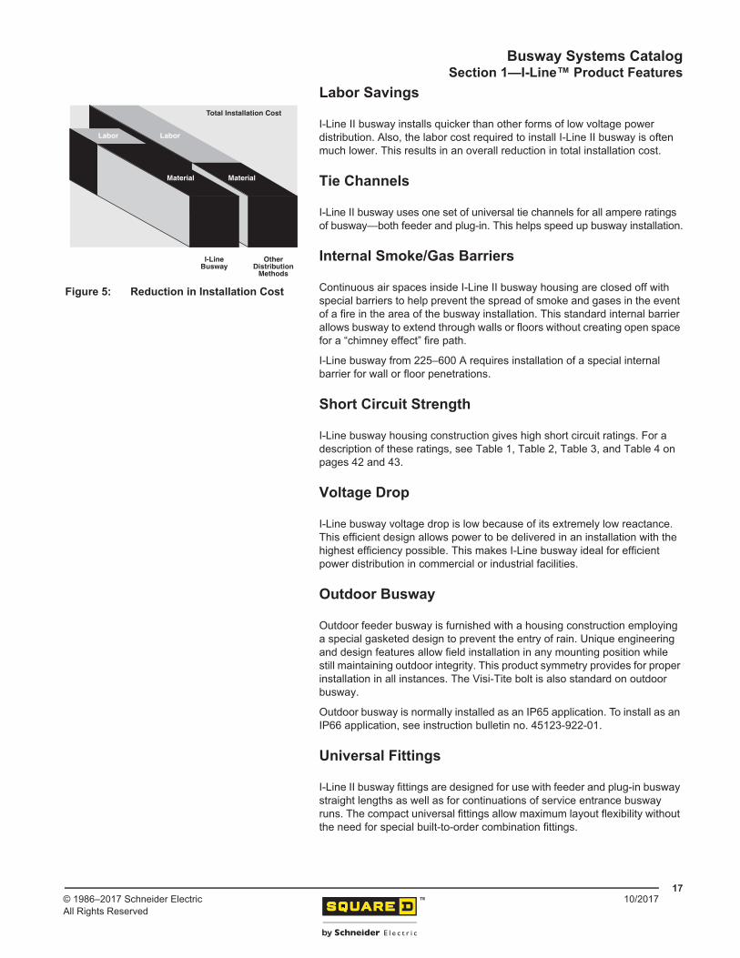
I-Line II busway installs quicker than other forms of low voltage power distribution. Also, the labor cost required to install I-Line II busway is often much lower. This results in an overall reduction in total installation cost.
Tie Channels
I-Line II busway uses one set of universal tie channels for all ampere ratings of busway—both feeder and plug-in. This helps speed up busway installation.
Internal Smoke/Gas Barriers
Continuous air spaces inside I-Line II busway housing are closed off with special barriers to help prevent the spread of smoke and gases in the event of a fire in the area of the busway installation. This standard internal barrier allows busway to extend through walls or floors without creating open space for a “chimney effect” fire path.
I-Line busway from 225–600 A requires installation of a special internal barrier for wall or floor penetrations.
Short Circuit Strength
I-Line busway housing construction gives high short circuit ratings. For a description of these ratings, see Table 1, Table 2, Table 3, and Table 4 on pages 42 and 43.
Voltage Drop
I-Line busway voltage drop is low because of its extremely low reactance. This efficient design allows power to be delivered in an installation with the highest efficiency possible. This makes I-Line busway ideal for efficient power distribution in commercial or industrial facilities.
Outdoor Busway
Outdoor feeder busway is furnished with a housing construction employing a special gasketed design to prevent the entry of rain. Unique engineering and design features allow field installation in any mounting position while still maintaining outdoor integrity. This product symmetry provides for proper installation in all instances. The Visi-Tite bolt is also standard on outdoor busway.
Outdoor busway is normally installed as an IP65 application. To install as an IP66 application, see instruction bulletin no. 45123-922-01.
Universal Fittings
I-Line II busway fittings are designed for use with feeder and plug-in busway straight lengths as well as for continuations of service entrance busway runs. The compact universal fittings allow maximum layout flexibility without the need for special built-to-order combination fittings.
Figure 5: Reduction in Installation Cost
Total Installation Cost
MaterialMaterial
LaborLabor
OtherDistribution
Methods
I-LineBusway
Busway Systems CatalogSection 1—I-Line™ Product Features
All I-Line busway products are manufactured in a Schneider Electric facility that has been registered by Underwriters Laboratories to ISO9001: 2015.
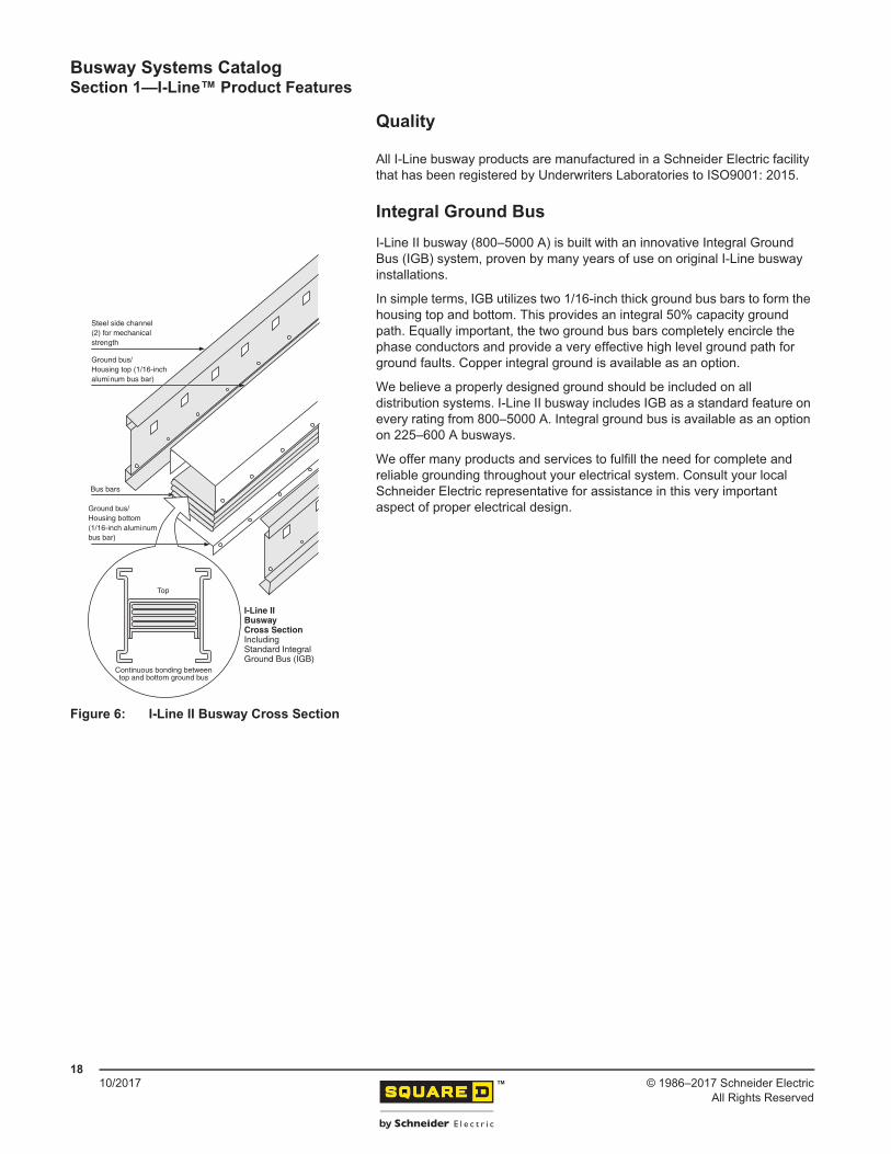
Integral Ground BusI-Line II busway (800–5000 A) is built with an innovative Integral Ground Bus (IGB) system, proven by many years of use on original I-Line busway installations.
In simple terms, IGB utilizes two 1/16-inch thick ground bus bars to form the housing top and bottom. This provides an integral 50% capacity ground path. Equally important, the two ground bus bars completely encircle the phase conductors and provide a very effective high level ground path for ground faults. Copper integral ground is available as an option.
We believe a properly designed ground should be included on all distribution systems. I-Line II busway includes IGB as a standard feature on every rating from 800–5000 A. Integral ground bus is available as an option on 225–600 A busways.
We offer many products and services to fulfill the need for complete and reliable grounding throughout your electrical system. Consult your local Schneider Electric representative for assistance in this very important aspect of proper electrical design.
Figure 6: I-Line II Busway Cross Section
I-Line IIBuswayCross SectionIncludingStandard IntegralGround Bus (IGB)
Ground bus/Housing top (1/16-inchaluminum bus bar)
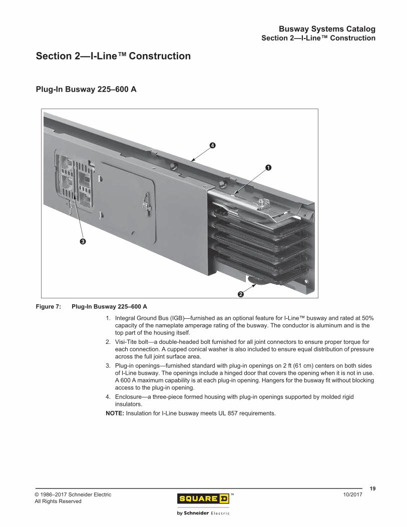
1. Integral Ground Bus (IGB)—furnished as an optional feature for I-Line™ busway and rated at 50% capacity of the nameplate amperage rating of the busway. The conductor is aluminum and is the top part of the housing itself.
2. Visi-Tite bolt—a double-headed bolt furnished for all joint connectors to ensure proper torque for each connection. A cupped conical washer is also included to ensure equal distribution of pressure across the full joint surface area.
3. Plug-in openings—furnished standard with plug-in openings on 2 ft (61 cm) centers on both sides of I-Line busway. The openings include a hinged door that covers the opening when it is not in use. A 600 A maximum capability is at each plug-in opening. Hangers for the busway fit without blocking access to the plug-in opening.
4. Enclosure—a three-piece formed housing with plug-in openings supported by molded rigid insulators.
NOTE: Insulation for I-Line busway meets UL 857 requirements.
Figure 7: Plug-In Busway 225–600 A
Busway Systems CatalogSection 2—I-Line™ Construction
1. Molded plug-in opening insulator—adds insulation and support at plug-in contact area.2. EZ Joint Pak connector assembly—includes like-phase connector on higher ampere ratings with
more than one conductor per phase (plug-in bus only).3. Ground jaw for plug-in unit—has a “blow-on” design similar to phase jaw connection.4. Fittings—includes elbows, tees, and flanged ends that are easily removed and refitted with the use
of our EZ Joint Pak assembly without disturbing adjacent lengths.NOTE:
— Internal barriers are standard on both feeder and plug-in busway. All interior spaces are barriered to stop hot gases.
— Hangers fit both feeder and plug-in busway without blocking access to openings.— I-Line plug-in units (15–1600 A) fit both original and I-Line II busway.— I-Line II plug-in busway with sandwich construction also includes the feeder-style features
shown on page 21.
Figure 8: Plug-In Busway 800–5000 A
Busway Systems CatalogSection 2—I-Line™ Construction
1. Steel housing channels—provides mechanical strength.2. Molded extra-strength glass fiber interphase barriers.3. EZ Joint Pak connector assembly—removable for isolation or maintenance. Includes Visi-Tite bolt.4. Steel/aluminum housing—reduces hysteresis and eddy current losses on feeder and plug-in
busway.5. Plated aluminum or copper bus bars.6. Surge clamps for added short circuit strength.7. Integral Ground Bus (IGB)—two, 1/16-inch thick aluminum bus bar. Also serves as top and bottom
housing.
NOTE:
— Polyester powder paint process—provides lasting uniform performance.— Housing sizes—the same for I-Line II feeder and plug-in busway. Same accessories fit both.— Insulation for I-Line busway meets UL 857 requirements.
Figure 9: Indoor Feeder Busway 800–5000 A
Busway Systems CatalogSection 2—I-Line™ Construction
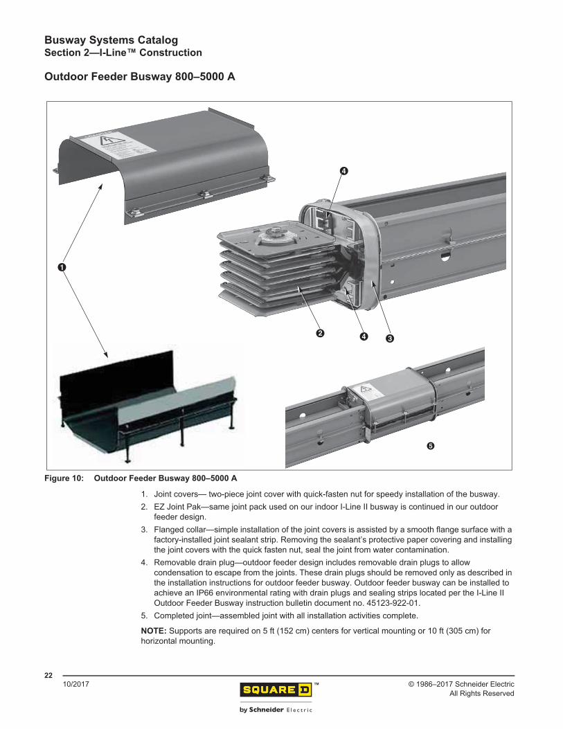
1. Joint covers— two-piece joint cover with quick-fasten nut for speedy installation of the busway.2. EZ Joint Pak—same joint pack used on our indoor I-Line II busway is continued in our outdoor
feeder design. 3. Flanged collar—simple installation of the joint covers is assisted by a smooth flange surface with a
factory-installed joint sealant strip. Removing the sealant’s protective paper covering and installing the joint covers with the quick fasten nut, seal the joint from water contamination.
4. Removable drain plug—outdoor feeder design includes removable drain plugs to allow condensation to escape from the joints. These drain plugs should be removed only as described in the installation instructions for outdoor feeder busway. Outdoor feeder busway can be installed to achieve an IP66 environmental rating with drain plugs and sealing strips located per the I-Line II Outdoor Feeder Busway instruction bulletin document no. 45123-922-01.
5. Completed joint—assembled joint with all installation activities complete.
NOTE: Supports are required on 5 ft (152 cm) centers for vertical mounting or 10 ft (305 cm) for horizontal mounting.
Figure 10: Outdoor Feeder Busway 800–5000 A
Busway Systems CatalogSection 2—I-Line™ Construction
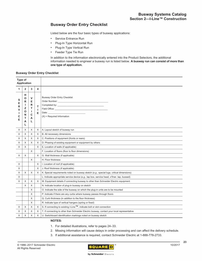
Listed below are the four basic types of busway applications:
• Service Entrance Run• Plug-In Type Horizontal Run• Plug-In Type Vertical Run• Feeder Type Tie Run
In addition to the information electronically entered into the Product Selectors, the additional information needed to engineer a busway run is listed below. A busway run can consist of more than one type of application.
NOTES:
1. For detailed illustrations, refer to pages 24–33.2. Missing information will cause delays in order processing and can affect the delivery schedule.3. If additional assistance is required, contact Schneider Electric at 1-888-778-2733.
Busway Order Entry Checklist
Type ofApplication
1 2 3 4
Busway Order Entry ChecklistOrder Number: _______________________________________ Completed by: ____________________________________Field Office: _________________________________________ Date: _____________________________(X) = Required Information
SERVICE
HORIZONTAL
VERTICAL
TIE
X X X X A. Layout sketch of busway run
X X X X B. All necessary dimensions
X X X X C. Positions of equipment (fronts or rears)
X X X X D. Phasing of existing equipment or equipment by others
X X X E. Location of walls (if applicable)
X F. Location of floors (floor to floor dimensions)
X X X G. Wall thickness (if applicable)
X H. Floor thickness
X X I. Location of roof (if applicable)
X X J. Roof thickness (if applicable)
X X X X K. Special requirements noted on busway sketch (e.g., special lugs, critical dimensions)
X L. Indicate appropriate service device (e.g., tap box, service head, x’fmer. tap, bussed)
X X X X M. Equipment details if connecting busway to other than Schneider Electric equipment
X X N. Indicate location of plug-in busway on sketch
X O. Indicate the side of the busway on which the plug-in units are to be mounted
X P. Indicate if there are any curbs where busway passes through floors
X Q. Curb thickness (in addition to the floor thickness)
X R. Indicate type of vertical hangers (spring or fixed)
X X X X S. If connecting to existing I-Line™, indicate bolt or slot connection
X X X X T. If connecting to other than Schneider Electric busway, contact your local representative
X X X X U. Switchboard identification markings noted on busway sketch
Busway Systems CatalogSection 3—I-Line™ Application Data
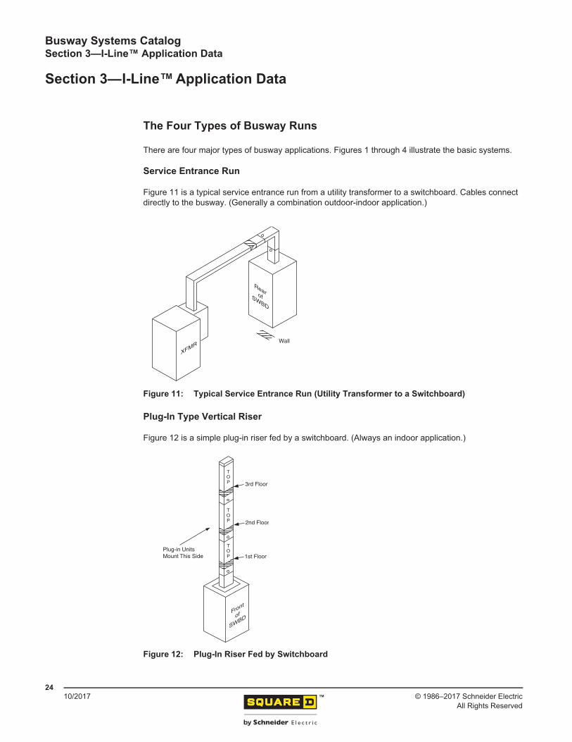
There are four major types of busway applications. Figures 1 through 4 illustrate the basic systems.
Service Entrance Run
Figure 11 is a typical service entrance run from a utility transformer to a switchboard. Cables connect directly to the busway. (Generally a combination outdoor-indoor application.)
Plug-In Type Vertical Riser
Figure 12 is a simple plug-in riser fed by a switchboard. (Always an indoor application.)
Figure 11: Typical Service Entrance Run (Utility Transformer to a Switchboard)
Figure 12: Plug-In Riser Fed by Switchboard
XFMR
RearofSWBD
Wall
Front
of
SWBD
3rd Floor
Plug-in UnitsMount This Side
2nd Floor
TOP
TOP
TOP 1st Floor
Busway Systems CatalogSection 3—I-Line™ Application Data
Service Entrance RunsI-Line II busway can be used as a service entrance conductor to bring power from a utility transformer into a distribution switchboard. Cable or solid bussing is used to connect to the transformer.
When the transformer is connected to the busway using cables, the governing electrical code can specify height clearance requirements for the cables.
Figure 15 illustrates the dimensions to consider when planning this type of run.
Service Heads
If the busway specifications or local utility require the service entrance cable-to-busway termination to be enclosed in a weatherproof box, then a service head should be ordered.
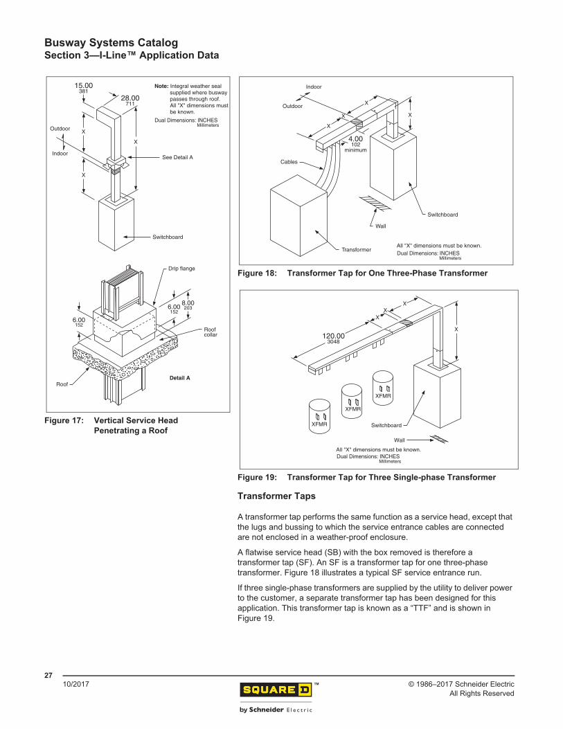
If the flatwise busway elevation is too low to allow a cable connection that would comply with the electrical code, the vertical service head (SV) could solve this issue. The SV is attached to busway that exits the rear of the switchboard and is turned upward (see Figure 16) or is attached to busway that exits the top of a switchboard and extends through the roof (see Figure 17 on page 27).
If a vertical service head extends through a roof, the roof must be sealed around the busway. To do this, a fixed collar must be factory assembled onto the section of busway that penetrates the roof. The contractor can then install flashing from the collar to the roof. A roof flange kit can be ordered from the factory to make the flashing job easier. The kit consists of a drip flange and a roof collar. When installed, the roof collar must be sealed to ensure that no moisture gets indoors. The roof flange kit will accommodate a roof slope up to one inch per foot. See Detail A in Figure 17 on page 27.
Figure 15: Typical Connection of Transformer to Busway using Cables
X
For X dimensions,refer to NEC Article 230-24.
X
X
X
®
Figure 16: Typical Vertical Service Head Application
Vertical servicehead
28.00711
29.00737
X
X
XX
Refer to code for minimumheight requirements.
Ground level
Outdoor
All "X" dimensions must be known.Note: Switchboard phasing must also be known.
Indoor
Dual Dimensions: INCHESMillimeters
Busway Systems CatalogSection 3—I-Line™ Application Data
A transformer tap performs the same function as a service head, except that the lugs and bussing to which the service entrance cables are connected are not enclosed in a weather-proof enclosure.
A flatwise service head (SB) with the box removed is therefore a transformer tap (SF). An SF is a transformer tap for one three-phase transformer. Figure 18 illustrates a typical SF service entrance run.
If three single-phase transformers are supplied by the utility to deliver power to the customer, a separate transformer tap has been designed for this application. This transformer tap is known as a “TTF” and is shown in Figure 19.
Figure 17: Vertical Service Head Penetrating a Roof
Note: Integral weather seal supplied where busway passes through roof. All "X" dimensions must be known.
Outdoor
IndoorSee Detail A
X
Switchboard
Drip flange
15.00381
28.00711
Roof
Roofcollar
6.00152
8.00203
Detail A
6.00152
X
X
Dual Dimensions: INCHESMillimeters
Figure 18: Transformer Tap for One Three-Phase Transformer
Figure 19: Transformer Tap for Three Single-phase Transformer
Indoor
Outdoor
Cables
Switchboard
All "X" dimensions must be known.
Wall
Transformer
4.00102
minimum
X
X
X
X
Dual Dimensions: INCHESMillimeters
All "X" dimensions must be known.
Wall
X
X
Switchboard
120.003048
XFMR
XFMR
XFMR
X
X
Dual Dimensions: INCHESMillimeters
Busway Systems CatalogSection 3—I-Line™ Application Data
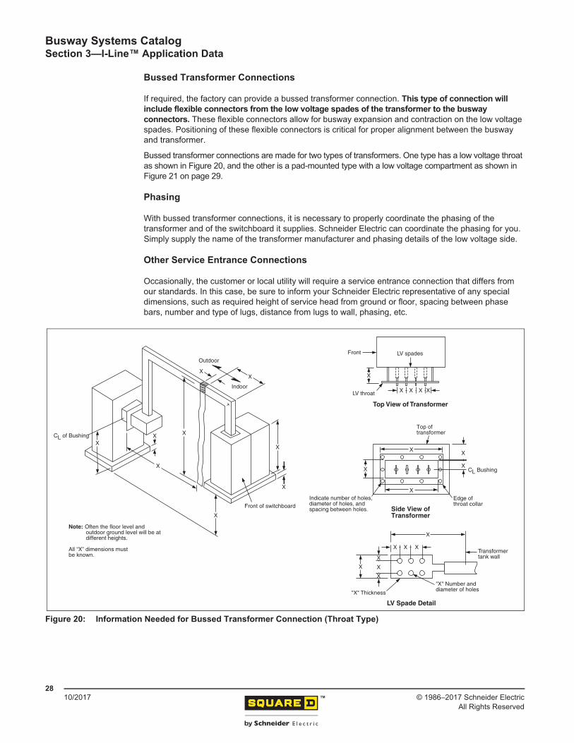
If required, the factory can provide a bussed transformer connection. This type of connection will include flexible connectors from the low voltage spades of the transformer to the busway connectors. These flexible connectors allow for busway expansion and contraction on the low voltage spades. Positioning of these flexible connectors is critical for proper alignment between the busway and transformer.
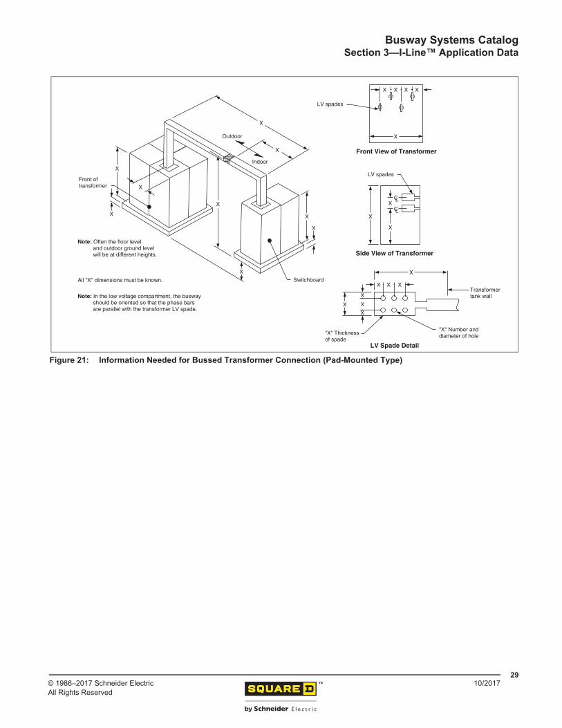
Bussed transformer connections are made for two types of transformers. One type has a low voltage throat as shown in Figure 20, and the other is a pad-mounted type with a low voltage compartment as shown in Figure 21 on page 29.
Phasing
With bussed transformer connections, it is necessary to properly coordinate the phasing of the transformer and of the switchboard it supplies. Schneider Electric can coordinate the phasing for you. Simply supply the name of the transformer manufacturer and phasing details of the low voltage side.
Other Service Entrance Connections
Occasionally, the customer or local utility will require a service entrance connection that differs from our standards. In this case, be sure to inform your Schneider Electric representative of any special dimensions, such as required height of service head from ground or floor, spacing between phase bars, number and type of lugs, distance from lugs to wall, phasing, etc.
Figure 20: Information Needed for Bussed Transformer Connection (Throat Type)
Indicate number of holes,diameter of holes, and spacing between holes.
Transformer tank wall
"X" Number anddiameter of holes
LV Spade Detail
"X" Thickness
Top View of Transformer
LV throat
LV spades
CL of Bushing
Outdoor
Indoor
Top of transformer
CL Bushing
Edge ofthroat collar
Side View ofTransformer
XX X
X
X
X
X X X X
XX
X
X
X
X X X
X X
X
X
X
X
XX
X
Front of switchboard
Front
Note: Often the floor level and outdoor ground level will be at different heights.
All “X” dimensions mustbe known.
Busway Systems CatalogSection 3—I-Line™ Application Data
Plug-in busway is used as a means of bringing power from a distribution switchboard to multiple loads throughout a building or manufacturing facility.
Phasing
A typical I-Line II plug-in run is shown in Figure 22. The phasing shown on the plug-in busway is “GABCN” top to bottom, with the top located as shown for a horizontal run. This phasing arrangement must always be followed to help ensure proper phasing of the plug-in units (see Detail A). Because this busway phasing must be followed, it is the busway that will determine the phasing of the switchboard.
NOTE: Plug-in busway has the integral ground bus plug-in jaw on the top side only.
Identification
When submitting busway run sketches for review, ensure that the plug-in busway sections are marked (P).
Figure 22: Measurements Needed for a Typical Plug-In Type Run
XP
P
P
P
Rear of switchboard
P
P
NCBAG
All “X” dimensions must be known. Indicates plug-in devices.
Unfusedreducer
Endclosure
Endclosure
GABCN G
ABCN
Plug-inunit
X
X X
X
X
X
X
X
X
CL
Top
Top
Top
Top
Top
Detail A “Hook-Swing” Mounting
Notches in top rail position unit. Hooks support weight of device during installation.
Top
GABCN
Busway Systems CatalogSection 3—I-Line™ Application Data
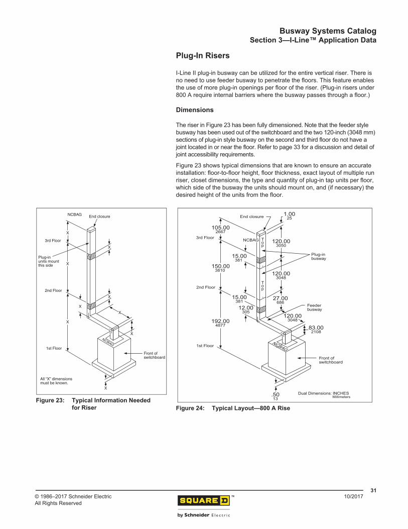
I-Line II plug-in busway can be utilized for the entire vertical riser. There is no need to use feeder busway to penetrate the floors. This feature enables the use of more plug-in openings per floor of the riser. (Plug-in risers under 800 A require internal barriers where the busway passes through a floor.)
Dimensions
The riser in Figure 23 has been fully dimensioned. Note that the feeder style busway has been used out of the switchboard and the two 120-inch (3048 mm) sections of plug-in style busway on the second and third floor do not have a joint located in or near the floor. Refer to page 33 for a discussion and detail of joint accessibility requirements.
Figure 23 shows typical dimensions that are known to ensure an accurate installation: floor-to-floor height, floor thickness, exact layout of multiple run riser, closet dimensions, the type and quantity of plug-in tap units per floor, which side of the busway the units should mount on, and (if necessary) the desired height of the units from the floor.
Figure 23: Typical Information Needed for Riser
Front ofswitchboard
Plug-inunits mountthis side
2nd Floor
End closure
1st Floor
3rd Floor
All “X” dimensionsmust be known.
X
X
X
X
X
X
X
X
X
NCBAG
NCBAG
Figure 24: Typical Layout—800 A Rise
Front ofswitchboard
Feederbusway
Plug-inbusway
3rd Floor
End closure
1st Floor
2nd Floor
120.003048
120.003050
1.0025
27.00686
15.00381
15.00381
12.00305
120.003048
83.002108
.5013
150.003810
105.002667
192.004877
Top
Top
NCBAG
NCBAG
Dual Dimensions: INCHESMillimeters
Busway Systems CatalogSection 3—I-Line™ Application Data
Circuit breaker types 250 A and below and the 30 A, 60 A, and 100 A fusible type plug-in units can be mounted on either side of the busway in riser installations.
When fusible type plug-in units are being supplied, the location of the plug-in unit determines the phasing of the busway. NEC Article 404.6 and CEC Article 14.502 state: “Single throw knife switches shall be mounted so that gravity will not tend to close them.” It is essential that the busway is oriented with the correct side available for the insertion of the units.
To determine the correct busway orientation (based on where the plug-in units mount for your installation), please contact your local representative for assistance and coordination.
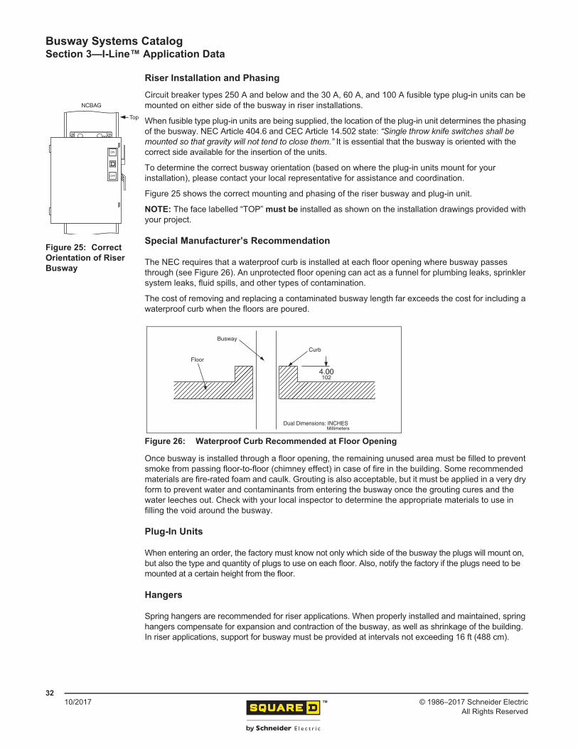
Figure 25 shows the correct mounting and phasing of the riser busway and plug-in unit.
NOTE: The face labelled “TOP” must be installed as shown on the installation drawings provided with your project.
Special Manufacturer’s Recommendation
The NEC requires that a waterproof curb is installed at each floor opening where busway passes through (see Figure 26). An unprotected floor opening can act as a funnel for plumbing leaks, sprinkler system leaks, fluid spills, and other types of contamination.
The cost of removing and replacing a contaminated busway length far exceeds the cost for including a waterproof curb when the floors are poured.
Once busway is installed through a floor opening, the remaining unused area must be filled to prevent smoke from passing floor-to-floor (chimney effect) in case of fire in the building. Some recommended materials are fire-rated foam and caulk. Grouting is also acceptable, but it must be applied in a very dry form to prevent water and contaminants from entering the busway once the grouting cures and the water leeches out. Check with your local inspector to determine the appropriate materials to use in filling the void around the busway.
Plug-In Units
When entering an order, the factory must know not only which side of the busway the plugs will mount on, but also the type and quantity of plugs to use on each floor. Also, notify the factory if the plugs need to be mounted at a certain height from the floor.
Hangers
Spring hangers are recommended for riser applications. When properly installed and maintained, spring hangers compensate for expansion and contraction of the busway, as well as shrinkage of the building. In riser applications, support for busway must be provided at intervals not exceeding 16 ft (488 cm).
Figure 25: Correct Orientation of Riser Busway
ON
OFF
NCBAG
Top
Figure 26: Waterproof Curb Recommended at Floor Opening
Floor
Busway
Curb
4.00102
Dual Dimensions: INCHESMillimeters
Busway Systems CatalogSection 3—I-Line™ Application Data
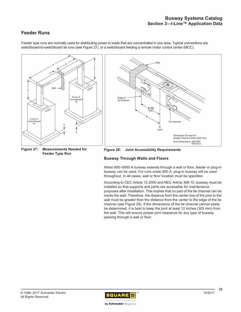
Feeder type runs are normally used for distributing power to loads that are concentrated in one area. Typical connections are switchboard-to-switchboard tie runs (see Figure 27), or a switchboard feeding a remote motor control center (MCC).
Busway Through Walls and Floors
When 800–5000 A busway extends through a wall or floor, feeder or plug-in busway can be used. For runs under 800 A, plug-in busway will be used throughout. In all cases, wall or floor location must be specified.
According to CEC Article 12.2000 and NEC Article 368.10, busway must be installed so that supports and joints are accessible for maintenance purposes after installation. This implies that no part of the tie channel can be inside the wall. Therefore, the distance from the center line of the joint to the wall must be greater than the distance from the center to the edge of the tie channel (see Figure 28). If the dimensions of the tie channel cannot easily be determined, it is best to keep the joint at least 12 inches (305 mm) from the wall. This will ensure proper joint clearance for any type of busway passing through a wall or floor.
Figure 27: Measurements Needed for Feeder Type Run
X
X X
X
X
Front of Switchboard
“A”
Wall
X
Front of Switchboard
“B”
X
NCBAG
GABCN
Figure 28: Joint Accessibility Requirements
B
Edge oftie channel
Dimension B must begreater than 8 inches (203 mm).
Tie channel
Wall
CLJoint
8.00203
Dual Dimensions: INCHESMillimeters
Busway Systems CatalogSection 4—I-Line™ Layout and Measurement
From the bid documents, specifications, and/or factory drawings, the following information is known:
• Busway is to be 1600 A, 3Ø4W, 50% GND, aluminum feeder busway. Width is determined to be 8.84 in. (225 mm).
• Switchboard is 7 ft x 7.5 in. (213 cm x 191 mm) high, 3 ft (91 cm) wide, and 2 ft (61 cm) deep. Busway connection to be in top center.
• Motor control center is 7 ft x 7.5 in. (213 cm x 191 mm) high with a 1 ft (30 cm) additional height pull box for busway connection; 20 in. (508 mm) wide; 20 in. (508 mm) deep. Busway connection is in top center.
• Bottom of busway (BOB.) to be installed 16 ft (488 cm) above finished floor (AFF) unless obstructed.
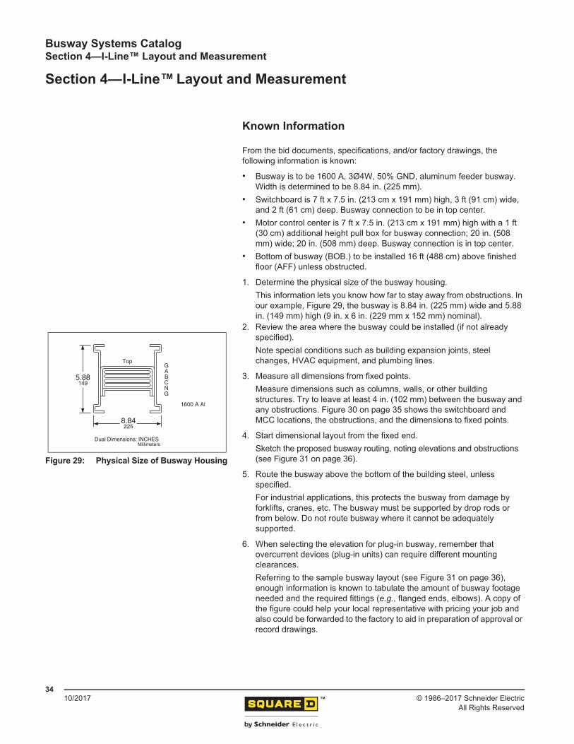
1. Determine the physical size of the busway housing.This information lets you know how far to stay away from obstructions. In our example, Figure 29, the busway is 8.84 in. (225 mm) wide and 5.88 in. (149 mm) high (9 in. x 6 in. (229 mm x 152 mm) nominal).
2. Review the area where the busway could be installed (if not already specified). Note special conditions such as building expansion joints, steel changes, HVAC equipment, and plumbing lines.
3. Measure all dimensions from fixed points.Measure dimensions such as columns, walls, or other building structures. Try to leave at least 4 in. (102 mm) between the busway and any obstructions. Figure 30 on page 35 shows the switchboard and MCC locations, the obstructions, and the dimensions to fixed points.
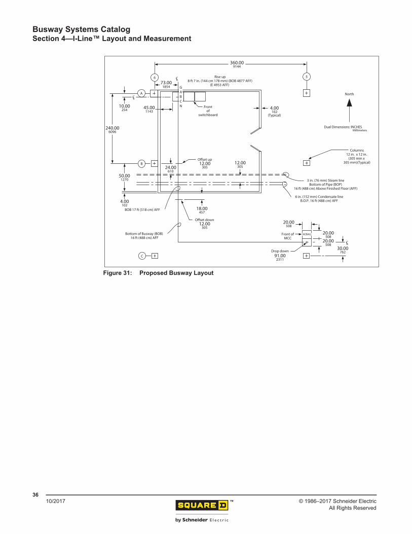
4. Start dimensional layout from the fixed end.Sketch the proposed busway routing, noting elevations and obstructions (see Figure 31 on page 36).
5. Route the busway above the bottom of the building steel, unless specified. For industrial applications, this protects the busway from damage by forklifts, cranes, etc. The busway must be supported by drop rods or from below. Do not route busway where it cannot be adequately supported.
6. When selecting the elevation for plug-in busway, remember that overcurrent devices (plug-in units) can require different mounting clearances.Referring to the sample busway layout (see Figure 31 on page 36), enough information is known to tabulate the amount of busway footage needed and the required fittings (e.g., flanged ends, elbows). A copy of the figure could help your local representative with pricing your job and also could be forwarded to the factory to aid in preparation of approval or record drawings.
Figure 29: Physical Size of Busway Housing
TopGABCNG
8.84225
5.88149
1600 A Al
Dual Dimensions: INCHESMillimeters
Busway Systems CatalogSection 4—I-Line™ Layout and Measurement
Section 5—I-Line™ Installation, Special Features, and Services
Installation Recommendations
To make the busway installation proceed as quickly and efficiently as possible, a few preliminary steps should be taken.
1. Familiarize yourself with the busway routing. If record drawings were supplied by the factory, have a copy accessible to the installers.
2. Inspect busway for damage when received. Store busway in a clean, dry location.3. Have the following tools available for the busway installation:
4. Carefully read the installation instructions for all devices and NEMA Publication BU 1.1 provided with the busway before installing any of the equipment. This will help ensure proper installation and operation procedures are followed for the busway system being installed. Note the instructions call for the busway to be “megger” tested before and after installation.
5. Install busway hangers and supports. The most common method of supporting the busway hangers is threaded drop rods (or all thread), which the installer must supply.
6. Anticipate the weight of the objects being installed so the necessary lifting devices and manpower are available.
7. If any problems are encountered or questions arise, contact your local Schneider Electric representative.
8. Once the installation of the busway is complete, NEMA Publication BU 1.1 should be delivered to the facility owner for his or her use in operating and maintaining the busway system.
Painting Installed Busway Systems
A busway system that includes plug-in units can be painted after installation. However, all precautions must be taken to prevent the paint from coming in contact with conductors and insulation. All nameplates and labels (safety labels, serial number labels, UL labels, etc.) must remain visible and legible.
Hanger Spacing
Normally, the support for outdoor busway is in the form of a customer-supplied T-stand type device. However, hangers are available from Schneider Electric when drop rods can be used.
Maximum support intervals include:
• Vertical mounting— indoor–16 ft (488 cm)— outdoor–10 ft (305 cm)
• Horizontal mounting— indoor–10 ft (305 cm)— outdoor–5 ft (152 cm)
— 1/2-in. (13 mm) nut driver or socket and rachet— Torque wrench or breaker bar with 5/8-inch (16 mm) head— 3/4-in. (19 mm) socket for torque wrench or breaker bar— Busway assembly tool (AT-2) for 800–5000 A (provided by Schneider Electric)— Level— 6 ft. tape measure or wooden ruler— Busway insulation tester (“megger,” 1000 V recommended)
Busway Systems CatalogSection 5—I-Line™ Installation, Special Features, and Services
NEMA Publication BU 1.1 is provided with each busway project as a guide for proper installation, operation, and maintenance of busway products. This publication addresses such areas as inspection of all electrical joints and terminals for tightness, preventing the entry of water and contaminants into the busway, instructions for what to do if water and contaminants do enter the busway, and other maintenance topics. This publication is also available upon request by contacting your local Schneider Electric representative.
Other publications Schneider Electric recommends to help ensure the highest quality of product performance are as follows:
— NFPA 70–National Electrical Code (U.S.)— NFPA 70B–Maintenance of Electrical Equipment— NEMA BU 1–Busway Standard published by the National Electrical Manufacturers Association— CSA C22.1–Canadian Electrical Code, Part 1
Figure 32: General Danger Safety Label
HAZARD OF ELECTRIC SHOCK, EXPLOSION, OR ARC FLASH
• Apply appropriate personal protective equipment (PPE) and follow safe electrical work practices. See NFPA 70E, NOM-029-STPS-2011, and CSA Z462.
• This equipment must be installed and serviced only by qualified personnel.• Perform such work only after reading and understanding all of the
instructions contained in this bulletin.• Turn off all power supplying this equipment before working on or
inside equipment.• Before performing visual inspections, tests, or maintenance on this
equipment, disconnect all sources of electric power. Assume all circuits are live until they are completely de-energized, tested, and tagged. Pay particular attention to the design of the power system. Consider all sources of power, including the possibility of backfeeding.
• Always use a properly rated voltage sensing device to confirm power is off.• Handle this equipment carefully and install, operate, and maintain it
correctly in order for it to function properly. Neglecting fundamental installation and maintenance requirements may lead to personal injury, as well as damage to equipment or other property.
• Disconnect the neutral connection at any Surge Protective Device (SPD) or other electronic device prior to performing electrical insulation resistance tests; reconnect to the device after testing.
• Carefully inspect your work area and remove any tools and objects left inside the equipment.
• Replace all devices, doors, and covers before turning on power to this equipment.
• All instructions in this bulletin assume that the customer has taken these measures before performing maintenance or testing.
Failure to follow these instructions will result in death or serious injury.
DANGER
Busway Systems CatalogSection 5—I-Line™ Installation, Special Features, and Services
This section outlines requirements for busways with features other than our standard.
Special Paint
I-Line™ busway can be provided in colors other than ANSI 49 gray for an additional fee. The special color requested should be specified by an ANSI color code at the time of order entry. With typically lengthened lead times for special color parts, it is imperative to provide this information as early as possible in the order process so delivery commitments can be met.
Low Current Density Busway
Some customers require a lower current density busway than our standard for rigorous duty in their installation. Schneider Electric has developed a range of busway for the most commonly requested current density of 1000 A per square inch for copper busway and 750 A per square inch for aluminum busway. If you require this current density for your installation, specify it, and we can meet your need. If you have requests for another specific current density, contact your local Schneider Electric representative.
Riser Plug-In Busway
Schneider Electric also offers an I-Line II plug-in busway specifically designed for installation in riser closets of high-rise buildings. This plug-in busway has a plug-in door on the front side that faces out into the room. The back of the busway, which faces the wall, is blanked off with a feeder bus side rail.
This design provides a plug-in busway ideally suited for riser cabinets and gives the customer only the necessary plug-in openings. The catalog number for this device is the same as our plug-in busway, except an R is substituted for the P. (Example: if the standard plug-in busway prefix is AP2512G, the riser busway prefix is AR2512G.)
Splash Resistant Busway
Some indoor busway is subject to occasional water exposure, such as roof leaks or sprinklers. While this application does not require the full protection of outdoor busway, additional protection is needed for the indoor busway. The splash resistant feature is tested to the International IEC 60529 standard and is rated as IP54. This rating specifies protection from dust (“limited ingress permitted with no harmful deposits”) and water (“splashed from all directions with limited ingress permitted”).
This feature is available as an option with indoor plug-in and feeder busway. It is identified by the addition of “M54” at the end of the standard catalog number.
Harmonic Busway
To properly allow for the impact of total harmonic distortion (THD), a busway solution must address both the current capacity of the neutral and the ability to dissipate the heat generated with the maximum anticipated load. The increased neutral currents will result in additional heating of all phase conductor bars, therefore de-rating of the busway is necessary.
With the Schneider Electric harmonic busway solutions, the neutral is sized to carry the full current of the expected harmonic load, while the increased cross section of the phase conductors dissipates the added heat generated within the busway.
There are two harmonic busway offers available:
• 15%<THD<35% rating (letter X in the catalog number)• THD>35% rating (letter Y in the catalog number)For example, if the standard busway prefix is AP2512G, the THD>35% harmonic busway prefix is APY2512G.
Busway Systems CatalogSection 5—I-Line™ Installation, Special Features, and Services
I-Line busway has been seismically qualified to meet the seismic provisions of the International Building Code (IBC), California Building Code (CBC), and ASCE/SEI 7 based on triaxial shake table testing following the code recognized test protocol ICC ES AC156. All qualification shake table testing was conducted by an independent test facility to verify compliance to an Ip = 1.5 by verifying post test equipment functionality as required by ASCE 7 for equipment that is part of a seismic designated system.
The shake table earthquake simulation subjected the busway test specimens to dynamic demands that can be more severe than the earthquake codes for most locations. A certificate of self certification is available on request from your local sales office and is based on site-specific, code-defined, seismic demand requirements for the installed location information supplied to Schneider Electric.
The qualified busway equipment must be installed, anchored, and restrained in accordance with Schneider Electric installation guidelines. For the purpose of seismic restraint design, the center of gravity is centrally located for all outside linear dimensions for each section or device (as listed along with their respective weights). Anchorage of equipment to the primary building structure is required to validate seismic certification of the equipment. The structural engineer or design engineer of record is responsible for design of the code compliant seismic restraint system for the building equipment. Schneider Electric is not responsible for the specification and performance of seismic restraint and anchorage systems.
Services
Schneider Electric offers a wide range of services to make the use of I-Line busway as simple as possible. A summary of these services follows:
Busway Measuring and Layout Service
Schneider Electric can provide full-site measuring and coordination of a busway installation. This service is ideal for large complicated projects requiring close coordination with other services. This service must be requested at the time of specification and order entry. Refer requests for this service to your local Schneider Electric representative.
Emergency Service
Trained and qualified busway personnel are on call 24 hours a day to assist in your emergency busway needs. Call Schneider Electric at 1-888-778-2733.
Busway Systems CatalogSection 5—I-Line™ Installation, Special Features, and Services
The “Missing Link” program is designed specifically to help a customer correct last minute changes to a project using busway. Those changes could include an unplanned obstruction requiring the busway to be rerouted, incorrect measurement of the busway run, or the need to order additional pieces to supplement busway previously ordered. The program applies to the United States, Canada, and Mexico, and guarantees shipment of factory-built busway in five to seven working days, or Schneider Electric pays for the premium freight. For complete details of the program, contact Schneider Electric at 1-888-778-2733.
How To Properly Measure Your Missing Link Dimensions
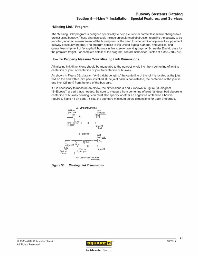
All missing link dimensions should be measured to the nearest whole inch from centerline of joint to centerline of joint, or centerline of joint to centerline of busway.
As shown in Figure 33, diagram “A–Straight Lengths,” the centerline of the joint is located at the joint bolt on the end with a joint pack installed. If the joint pack is not installed, the centerline of the joint is one inch (25 mm) from the end of the bus bars.
If it is necessary to measure an elbow, the dimensions X and Y (shown in Figure 33, diagram “B–Elbows”) are all that’s needed. Be sure to measure from centerline of joint (as described above) to centerline of busway housing. You must also specify whether an edgewise or flatwise elbow is required. Table 41 on page 76 lists the standard minimum elbow dimensions for each amperage.
Figure 33: Missing Link Dimensions
CL
CL Joint bolt
Endof bars
X
A - Straight LengthsWithoutjoint pak
Withjoint pak
CL Joint
CL Joint
CLBus
CL Bus
B - Elbows Withjoint pak
Without joint pak
YX
Endof bars
1.0025
1.0025
Dual Dimensions: INCHESMillimeters
Busway Systems CatalogSection 6—I-Line™ Electrical Data
• Standards: UL857 (File Number E22182); CSA C22.2 No. 27-1973 (File Number LL-61778)• Systems: AC–3Ø3W, 3Ø4W, 1Ø2W, 1Ø3W, DC-2 Pole. All neutrals are 100% capacity.• Voltage: 600 Volts AC/DC, 50 Hz and 60 Hz• Ground: 50% capacity as standard for 800–5000 A, as an option on 225–600 A• Enclosure: Indoor and outdoor (800–5000 A only)
NOTE: All values are for thermal rated busway. Contact Schneider Electric for other options such as low current density rated, harmonic rated, and IP54 rated.
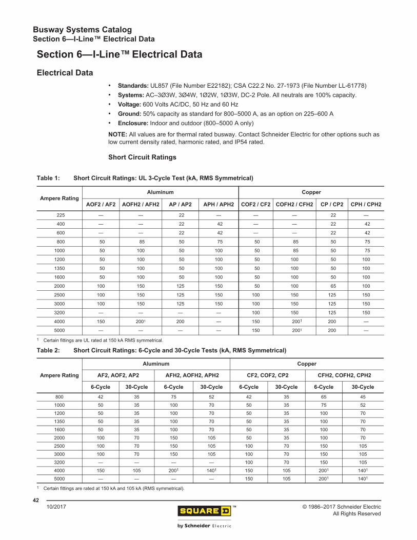
Short Circuit Ratings
Table 1: Short Circuit Ratings: UL 3-Cycle Test (kA, RMS Symmetrical)
NOTE: 225–600 A busway are connected in series with a Class J or T fuse; 800–5000 A are connected in series with a Class L fuse. All ratings are tested in compliance with UL/CSA standards. All ratings apply for three-pole and four-pole busway.
1 A 1200 A fuse is used in series.2 A 1600 A fuse is used in series.
Table 4: I-Line Short Circuit Ratings: KA, RMS Symmetrical (Series Connected with a Breaker)1
1 To maintain the short circuit rating of the system, fully rated plug-in units must be used or a system short circuit study must be made to determine the required interrupt ratings of any plug-in units.
Busway Systems CatalogSection 6—I-Line™ Electrical Data
NOTES:1. For optimized values on a specific application, contact your local Schneider Electric Representative.2. Impedance values are for busway operating at 176 °F (80 °C) temperature.
Table 6: Resistance Values for Aluminum Integral Ground Bus
Ampere Rating3Ø3W and 3Ø4W
DC Resistance (Milliohms per 100 Feet)
Aluminum Phase Conductors Copper Phase Conductors
225 8.1 8.1
400 6.4 6.4
600 5.3 6.4
800 4.0 4.4
1000 3.5 4.0
1200 3.2 3.5
1350 3.0 3.4
1600 2.8 3.0
2000 2.2 3.0
2500 2.0 2.2
3000 1.8 2.0
3200 — 1.7
4000 1.7 1.7
5000 — 1.7
NOTE: Resistance values are for integral ground bus operating at 176 °F (80 °C) temperature.
Busway Systems CatalogSection 6—I-Line™ Electrical Data
Voltage Drop Data (60 Hz At Rated Load)The values expressed below are based on a single concentrated load at the end of the busway run. For distributed loading, divide the values shown by two (2).
Table 7: Power Factor–Average Phase Line-To-Line Voltage Drop in Volts Per 100 ft (3048 cm)
NOTES:1. For optimized values on a specific application, contact your local Schneider Electric Representative.2. For balanced 3-phase line-to-line voltage drop 4-wire busway, use values from tables.3. For balanced 3-phase line-to-neutral voltage drop, multiply values from tables by .577.4. For single-phase voltage drop, multiply values from tables by 1.15.5. For other than rated current, multiply values from tables by Actual Current
Rated CurrentFor different lengths, multiply values from 60 Hz tables by Actual Footage
100 ft6. Voltage drop calculations for 50 Hz can be made by substituting the appropriate “x” value from page 47 into samples No.1 and 2 above. For other
frequency values (e.g., 400 Hz), contact your local Schneider Electric representative for assistance.7. For plug-in distributed loads, divide the voltage drop by 2. See IEEE Standard 141-13.8.3.
Busway Systems CatalogSection 6—I-Line™ Electrical Data
NOTES:1. For optimized values on a specific application, contact your local Schneider Electric Representative.2. For balanced 3-phase line-to-line voltage drop 4-wire busway, use values from tables.3. For balanced 3-phase line-to-neutral voltage drop, multiply values from tables by .577.4. For single-phase voltage drop, multiply values from tables by 1.15.5. For other than rated current, multiply values from tables by Actual Current
Rated CurrentFor different lengths, multiply values from 60 Hz tables by Actual Footage
100 ft6. Voltage drop calculations for 50 Hz can be made by substituting the appropriate “x” value from page 47 into samples No.1 and 2 above. For other frequency
values (e.g., 400 Hz), contact your local Schneider Electric representative for assistance.7. For plug-in distributed loads, divide the voltage drop by 2. See IEEE Standard 141-13.8.3.
Busway Systems CatalogSection 6—I-Line™ Electrical Data
Catalog numbers are composed of two basic parts—the prefix (shown below), plus the suffix of each individual busway component from pages 49–54.
The prefix contains necessary busway information except individual component descriptive details that are defined as the suffix. The catalog number prefix will generally remain unchanged throughout a busway run while the suffix will vary with each individual length or fitting selected.
A few devices, such as hangers, wall flanges, etc., do not follow the exact pattern described above. For these exceptions, a complete listing of device catalog numbers is shown with the individual device drawing(s) on pages 50 and 55–61.
Figure 34: I-Line 225–600 A Busway Catalog Numbering System
Bus Bar Material: A = Aluminum; C = Copper
Type of Busway: P = Plug-in
Special Features:(Optional) H= High short circuit bracing
Number of Poles: 3 = 3Ø3W; 5 = 3Ø4W 100%N
Ampere Rating: in hundreds of amperes (e.g., 04 = 400 amperes)
Ground Bus:(Optional) G = 50% capacity integral ground bus
Descriptive identification of individual piece
A P H – 5 04 G – 10
PrefixSuffix–of each individual buswaycomponent drawing beginning
on page 53.
Busway Systems CatalogSection 7—I-Line™ 225–600 A Busway
Table 12: Cable Tap Boxes (Plug-In)—Dimensions and Other Specifications
Ampere Rating
A B C D E1
1 Lugs in plug-in tap boxes can be reversed in field so that ends of lugs point in opposite direction from that shown on drawing (400 A and 600 A only).
Lugs Per Phase
and Neutral
GroundLug
Catalog Number (With Ground Bus)
IN mm IN mm IN mm IN mm IN mm 3-Pole Weight 3Ø4W 100% N Weight
NOTE: The National Electrical Code states that in Article 368-17(B) overcurrent protection is required where busways are reduced in ampacity except for certain industrial applications.
Table 15: Expansion Fitting–Application Data
Ampere Rating A
Aluminum Copper IN mm
225 225 4.51 114
400 400 5.57 141
— 600 5.57 141
600 — 6.95 176
Figure 44: Catalog Number Suffix–EJ Dimensions
15.76400
7.6319412.00
305
36.00914
60.001524
9.40239
8.13206
17.20437
Top
Front
ADual Dimensions: INCHES
Millimeters
NOTE: Expansion joint permits ± 1.5 in. (± 38 mm) expansion. Use recommended only when busway passes through building expansion joint.
Figure 45: Unfused Reducer Dimensions
36.00914
18.00457
18.00457
Top
Front
Dual Dimensions: INCHESMillimeters
Table 16: Unfused Reducer–Catalog Number SuffixBolt End
Ampere Rating Slot End Ampere Rating
225 400 600225 — — —400 -R02 — —600 -R02 -R041
1 Aluminum busway only.
—
Busway Systems CatalogSection 7—I-Line™ 225–600 A Busway
Sway braces are used when only one side of the busway is heavily loaded with tap-off units or when other factors could cause possible swaying of the busway.
Figure 52: Edgewise Hanger Dimensions
5.50140
2.0051
0.6216
2.1254
0.256
0.56 Dia. hole 14
Drop rod provided by customerB
A
CL Dual Dimensions: INCHESMillimeters
0.62 Dia. hole 16
1.5038
0.8822
1.9048
6.44163 1.87
47
AB
CL
Dual Dimensions: INCHESMillimeters
Nuts and drop rods provided by customers
Figure 53: Catalog Number HP-1-SBC Dimensions
Nuts, 1/2 in. (13 mm) drop rod, and beam clamp
supplied by customer Sway brace(As required)provided by customer
Buildingsupport
4.62117
8.00203Note: When required, the
recommended spacing is 20-foot (610 cm) centers.
Dual Dimensions: INCHESMillimeters
Busway Systems CatalogSection 7—I-Line™ 225–600 A Busway
Table 21: Hanger (Vertical Fixed)-–Dimensions and Catalog Numbers
Ampere Rating A BCatalog Number
Aluminum Copper IN mm IN mm
225 225 4.28 109 6.54 166 HP-2-V
400 400 5.32 135 7.58 192 HP-3-V
— 600 5.32 135 7.58 192 HP-3-V
600 — 6.70 170 8.96 228 HP-4-V
NOTE: Dimensions shown apply for 4 ft (122 cm), 6 ft (183 cm), 8 ft (244 cm), and 10 ft (305 cm) straight lengths only. Consult your local Schneider Electric representative for dimensions that apply for fractional straight lengths.
4.30109
9.38238
2.1254
11.50292
3.1881
1.1228
Top
Top Bottom
A
B
Floorlevel
CL Joint
To secure hanger tobusway, attach mountingscrew on bottom of buswayto hanger brace through slot.
.75-inch (19 mm) diameter holes for access to mounting screw on busway when securing hanger to busway mounting.
Note: Waterproof curbing is required around floor opening shown.
Customer to locate and drillfour (4) .31-inch (8 mm) diameter holesfor securing mountingchannel to hanger.
Channel iron and.50-inch (13 mm) diameter bolts by customer.
Dual Dimensions: INCHESMillimeters
Busway Systems CatalogSection 7—I-Line™ 225–600 A Busway
Table 22: Hanger (Vertical Spring)-–Dimensions and Catalog Numbers
Ampere Rating A BCatalog Number
Aluminum Copper IN mm IN mm
225 225 4.28 109 6.54 166 HP-2-VS
400 400 5.32 135 7.58 192 HP-3-VS
— 600 5.32 135 7.58 192 HP-3-VS
600 — 6.70 170 8.96 228 HP-4-VS
NOTE: Dimensions shown apply for 4 ft (122 cm), 6 ft (183 cm), 8 ft (244 cm), and 10 ft (305 cm) straight lengths only. Consult your local Schneider Electric representative for dimensions that apply for fractional straight lengths.
9.38238
8.31211
17.69449
CL JointBottomTop
A
B
1.1228
4.32110
4.32110
1.1228
Top
CL Joint
To secure hanger to busway,attach mounting screw onbottom of busway,to hanger brace.
Customer to locate and drill four(4) 0.31-inch (8 mm) diameter holes for securing mounting channel to hanger.
Channel iron and 0.50-inch (13 mm) diameter bolts by customer.
0.75-inch (19 mm) diameter holes for access to mounting screw onbusway when securing hanger to busway housing.
Floorlevel
Busway Systems CatalogSection 7—I-Line™ 225–600 A Busway
NOTE: For seismic applications, seismic hangers must be used for horizontally mounted busway. Standard vertical hangers should be used for vertically mounted busway.
Figure 56: Hanger (Horizontal Seismic) Dimensions
Table 23: Seismic Hanger—Dimensions
Ampere Rating (A) CatalogNumber
A B C
Aluminum Copper IN mm IN mm IN mm
225 225 HP2SH 6.21 158 3.61 92 5.01 127
400 400 / 600 HP3SH 7.34 186 4.74 120 6.14 156
600 — HP5SH 8.71 221 6.11 155 7.51 191
A
9.74
B
C
Flatwise
Edgewise
0.56 Dia. Typ.
0.56 x 0.56 Slot Typ.
Busway Systems CatalogSection 7—I-Line™ 225–600 A Busway
Catalog numbers are composed of three basic parts: the prefix (as shown), the body, plus the suffix of each individual busway component (see pages 65–89).
• The prefix contains the general busway type.• The body contains the number of poles, the amperage, and ground system.• The suffix contains the descriptive identification of the individual device.The catalog number prefix will generally remain unchanged throughout a busway run while the suffix will vary with each individual length or fitting selected.
A few devices, such as hangers, wall flanges, etc., do not follow the exact pattern described above. For these exceptions, a complete listing of device catalog numbers is shown with the individual device drawing(s) on pages 90–97.
2 = I-Line II Busway Designation
Optional Features:R = Density RatedX = Harmonic rated: 15% < THD < 35% Y = Harmonic rated: THD > 35%
Number of Poles:3 = 3Ø3W; 5 = 3Ø4W (100% N)
Optional Feature: H = High Short Circuit
Ampere Rating:in hundreds of amperes(e.g., 20 = 2000 amperes)
Type of Busway:OF = Outdoor FeederF = FeederR = Riser Plug-InP = Plug-In
Ground Bus:G = Aluminum, 50% capacity integral ground busGG = Copper, 50% capacity integral ground bus
Bus Bar Material:A = Aluminum, C = Copper
Descriptive identification of individual piece
NOTES: Harmonic rated cannot be combined with density rating. The 2 is omitted when both outdoor feeder (OF) and high short circuit (H) features are selected together.
C OF H R 2 – 3 20 G 10ST
PREFIX BODY NOTE: SUFFIX of each individual busway component beginning on page 65.
Figure 60: I-Line Busway Catalog Numbering System
Busway Systems CatalogSection 8—I-Line™ 800–5000 A Busway
Figure 61: Cross Sections—Plug-In and Indoor Feeder Lengths Dimensions
GABCNG
GABCNG
GABCNG
W
Top
W
Top
W
Top
5.88149
Figure A Figure B Figure C
Dual Dimensions: INCHESMillimeters
Figure 62: Cross Sections—Fittings and All Outdoor Feeder Dimensions
W
5.88149
.432 11
Figure A Figure B Figure CW W
1.2030
1.2030
Nominal clearance(Typical)
Dual Dimensions: INCHESMillimeters
.432 11
.432 11
.432 11
.432 11
.432 11
NOTE: Dotted line indicates the profile of the joint covers for Outdoor Feeder busway. The profile for indoor fittings is the same as the busway itself.
Table 27: Cross-Sections–Aluminum Content and Weight
AmpereRating
WFig.
Bus Bars Per PhaseApproximate Weights
3-Pole 4-Pole
IN mm IN mm Lb/Ft Kg/M Lb/Ft Kg/M
800 4.34 110 A One: 0.25 x 3 One: 6 x 76 11 17 12 18
1000 5.34 136 A One: 0.25 x 4 One: 6 x 10² 12 18 13 20
1200 6.34 161 A One: 0.25 x 5 One: 6 x 127 13 20 15 22
1350 7.34 186 A One: 0.25 x 6 One: 6 x 152 14 21 16 24
1600 8.84 225 A One: 0.25 x 6.5 One: 6 x 165 16 24 18 27
2000 12.72 323 B Two: 0.25 x 4 Two: 6 x 10² 21 32 25 37
2500 16.22 412 B Two: 0.25 x 5 Two: 6 x 127 25 37 30 44
3000 18.72 475 B Two: 0.25 x 6.5 Two: 6 x 165 28 42 34 50
4000 25.60 650 C Three: 0.25 x 6 Three: 6 x 152 38 57 45 67
Busway Systems CatalogSection 8—I-Line™ 800–5000 A Busway
800 3.84 98 A One: 0.25 x 2.5 One: 6 x 64 14 21 17 25
1000 4.34 110 A One: 0.25 x 2.5 One: 6 x 64 16 24 19 28
1200 5.34 136 A One: 0.25 x 3 One: 6 x 76 19 28 23 34
1350 5.84 148 A One: 0.25 x 4 One: 6 x 10² 21 31 25 37
1600 6.74 171 A One: 0.25 x 4.5 One: 6 x 114 23 35 30 44
2000 7.84 199 A One: 0.25 x 6 One: 6 x 152 27 39 33 49
2500 12.72 323 B Two: 0.25 x 4 Two: 6 x 10² 38 57 46 69
3000 15.22 387 B Two: 0.25 x 4.5 Two: 6 x 114 42 63 50 75
3200 16.22 412 B Two: 0.25 x 5 Two: 6 x 127 49 73 55 82
4000 23.60 599 C Three: 0.25 x 4 Three: 6 x 10² 63 94 77 114
5000 25.10 638 C Three: 0.25 x 5.4 Three: 6 x 137 77 114 95 141
NOTES:1. For required wall and floor openings, refer to page 96.2. Values are for thermal-rated busway. Contact Schneider Electric for other options such as low current density rated, harmonic
rated, and IP54 rated.
Figure 63: Straight Lengths—Feeder Dimensions
120.003048
Dual Dimensions: INCHESMillimeters
Maximum length:
NOTE: All straight lengths and fittings of feeder busway are fully compatible, rating for rating, with straight lengths of plug-in busway. Available in 1-in. (25 mm) increments from 16–120 in. (406–3048 mm).
Busway Systems CatalogSection 8—I-Line™ 800–5000 A Busway
Qwik flange is typically used only on Schneider Electric indoor equipment top exit/entry. Flanged end is typically used on all other Schneider Electric indoor/outdoor equipment, including third party equipment.
Figure 65: Qwik Flange
Figure 66: Flanged End
Busway Systems CatalogSection 8—I-Line™ 800–5000 A Busway
Qwik Flanges and closing plates are typically shipped with the switchboard/switchgear. The Qwik Flange closing plate closes the gap between the busway and the top of the gear. If a separate Qwik Flange or closing plate kit is needed, the catalog numbers can be created by adding the suffix "QF" or "CP" respectively to the prefix of the busway being installed. For example: AF2530GQF or CF2312GCP.
NOTE: Refer to “Detail of Phase Bussing Connections in a Switchboard” on page 75.
Figure 68: Legacy Aluminum and Copper Qwik Flange Dimensions
CL
1.2532
2.7971
B B
A C C CA A AAA
Figure 1 Figure 2 Figure 3
Dual Dimensions: INCHESMillimeters
Table 31: Legacy Aluminum Qwik Flange–Application Data
Aluminum Ampere Rating
Fig.A B C
IN mm IN mm IN mm
800 1 3.00 76 — — — —
1000 1 4.00 102 — — — —
1200 1 5.00 127 — — — —
1350 1 6.00 152 — — — —
1600 1 7.50 191 — — — —
2000 2 4.50 114 11.38 289 2.38 60
2500 2 6.00 152 14.88 378 2.88 73
3000 2 7.50 191 17.38 441 2.38 60
4000 3 6.50 165 24.26 616 2.38 60
Table 32: Legacy Copper Qwik Flange–Application Data
Copper Ampere Rating Fig.
A B C
IN mm IN mm IN mm
800 1 2.50 64 — — — —
1000 1 3.00 76 — — — —
1200 1 4.00 102 — — — —
1350 1 4.50 114 — — — —
1600 1 5.40 137 — — — —
2000 1 6.50 165 — — — —
2500 2 4.50 114 11.38 289 2.38 60
3000 2 5.00 127 13.88 353 3.88 86
3200 2 6.00 152 14.88 378 2.88 73
4000 3 4.50 114 22.26 565 4.38 111
5000 3 6.00 152 23.76 604 2.88 73
Figure 69: Legacy Qwik Flange Dimensions
Dual Dimensions: INCHESMillimeters
4.00102
4.00102
4.00102
4.00102
4.00102
Busway Systems CatalogSection 8—I-Line™ 800–5000 A Busway
New Qwik Flanges and closing plates are typically shipped with the switchboard/switchgear. The new Qwik Flange closing plate closes the gap between the busway and the top of the gear. If a separate new Qwik Flange or closing plate kit is needed, the catalog numbers can be created by adding the
Figure 71: New Aluminum and Copper Qwik Flange (Indoor Only) Dimensions
CL
2.7971
B B
A C C CA A AAA
Figure 1 Figure 2 Figure 3
Dual Dimensions: INCHESMillimeters
1.4036
Table 34: Aluminum New Qwik Flange–Application Data
Aluminum Ampere Rating
Fig.A B C
IN mm IN mm IN mm
800 1 3.00 76 — — — —
1000 1 4.00 102 — — — —
1200 1 5.00 127 — — — —
1350 1 6.00 152 — — — —
1600 1 7.50 191 — — — —
2000 2 4.50 114 11.38 289 2.38 60
2500 2 6.00 152 14.88 378 2.88 73
3000 2 7.50 191 17.38 441 2.38 60
4000 3 6.50 165 24.26 616 2.38 60
Table 35: Copper New Qwik Flange–Application Data
Copper Ampere Rating Fig.
A B C
IN mm IN mm IN mm
800 1 2.50 64 — — — —
1000 1 3.00 76 — — — —
1200 1 4.00 102 — — — —
1350 1 4.50 114 — — — —
1600 1 5.40 137 — — — —
2000 1 6.50 165 — — — —
2500 2 4.50 114 11.38 289 2.38 60
3000 2 5.00 127 13.88 353 3.88 86
3200 2 6.00 152 14.88 378 2.88 73
4000 3 4.50 114 22.26 565 4.38 111
5000 3 6.00 152 23.76 604 2.88 73
Figure 72: New Qwik Flange Dimensions
Dual Dimensions: INCHESMillimeters
5.00127
5.00127
5.00127
B
B
C C
5.00127
5.00127
Busway Systems CatalogSection 8—I-Line™ 800–5000 A Busway
Detail of Phase Bussing Connections in a Switchboard
NOTE: Schneider Electric switchgear and switchboards use a unique flange end. For details, contact your local Schneider Electric representative.
NOTICEHAZARD OF EQUIPMENT DAMAGEImproper contact pressure can cause overheating and equipment failure. Use 3-inch (76 mm) conical washers and Grade 5 hardwareto ensure proper contact pressure.
Failure to follow this instruction can result in equipment damage.
Figure 76: Switchboard Phase Bussing Connections
Bu sway flanged endor Qwik Flange
Grade 5 hardware
Large conical washers
Switchboard bussing
Tie connector(Used on 2 and 3 stackconfigurations only)
Square nut
Top of switchboard/switchgear
Sealing washer-outdoor only
Self tapping 1/4-20 screw
NOTE: For installation, maintenance, or relocation, use a torque wrench to tighten the bolt to 60–80 lb-ft (81–108 N•m).
Busway Systems CatalogSection 8—I-Line™ 800–5000 A Busway
Ampere Rating L Catalog NumberSuffixAluminum Copper IN mm
— 800 11.00 279 -LFM11
800 1000 11.00 279 -LFM11
1000 1200 12.00 305 -LFM12
1200 1350 12.00 305 -LFM12
— 1600 12.00 305 -LFM12
1350 2000 13.00 330 -LFM13
1600 — 13.00 330 -LFM13
2000 2500 15.00 381 -LFM15
— 3000 16.00 406 -LFM16
2500 — 17.00 432 -LFM17
— 3200 17.00 432 -LFM17
3000 — 18.00 457 -LFM18
— 4000 21.00 533 -LFM21
— 5000 21.00 533 -LFM21
4000 — 22.00 559 -LFM22
NOTE: Values are for thermal-rated busway. Contact Schneider Electric for other options such as low current density rated, harmonic rated, and IP54 rated.
11.00 279Min.
11.00 279Min.
Joint CL
L Min.
L Min.
Flatwise
JointCL
Dual Dimensions: INCHESMillimeters
Edgewise: Catalog Number Suffix–LEM11
Flatwise: Catalog Number Suffix–LFM
Busway Systems CatalogSection 8—I-Line™ 800–5000 A Busway
Edgewise: Catalog Number Suffix–OE Flatwise: Catalog Number Suffix–OF
Table 42: Flatwise Offset–Application Data
Ampere Rating L W
Aluminum Copper IN mm IN mm
800 800/1000 11.00 279 4.00 100
1000 1200 12.00 305 4.00 100
— 1350 12.00 305 4.00 100
1200 1600 12.00 305 6.00 150
1350 — 13.00 330 9.00 229
— 2000 13.00 330 9.00 229
1600 — 13.00 330 10.00 254
2000 2500 15.00 381 14.00 356
2500 — 17.00 432 16.00 406
— 3000 16.00 406 16.00 406
— 3200 17.00 432 16.00 406
3000 — 18.00 457 18.00 457
4000 — 22.00 559 25.00 635
— 4000 21.00 533 23.00 584
— 5000 21.00 533 25.00 635
NOTE: Values are for thermal-rated busway. Contact Schneider Electric for other options such as low current density rated, harmonic rated, and IP54 rated.
Busway Systems CatalogSection 8—I-Line™ 800–5000 A Busway
NOTE: Values are for thermal-rated busway. Contact Schneider Electric for other options such as low current density rated, harmonic rated, and IP54 rated.
L Min.
W Min.
11.00 279Min.
JointCL
L Min.
W Min.
11.00 279Min.
JointCL
Dual Dimensions: INCHESMillimeters
Catalog Number Suffix–DRCatalog Number Suffix–DL
Busway Systems CatalogSection 8—I-Line™ 800–5000 A Busway
NOTES:1. Values are for thermal-rated busway. Contact Schneider Electric for other options such as low current density rated, harmonic rated, and IP54 rated.2. Edgewise or flatwise cable tap box (end) are applicable on vertical applications.3. Due to the construction design, the edgewise and flatwise outdoor cable tap boxes are not interchangeable in the field.
Busway Systems CatalogSection 8—I-Line™ 800–5000 A Busway
NOTE: Values are for thermal-rated busway. Contact Schneider Electric for other options such as low current density rated, harmonic rated, and IP54 rated.
28.00711
B
C
A
D
48.00*1219
Dual Dimensions: INCHESMillimeters
C/L
C/L
* 3000 A / 3200 A / 4000 A / 5000 A Center Tap Box Length—60 in. (1524 mm)
Busway Systems CatalogSection 8—I-Line™ 800–5000 A Busway
NOTE: The National Electrical Code states in Article 368-17(B) that overcurrent protection is required where busways are reduced in ampacity except for certain industrial applications.
Figure 83: Cable Tap Box (Bolt On)
28.20716
23.50597
24.00610
15.00381
3.0076
4.00102
4.00102
1.4
10.50267
9.0022934.00
864(Hanger width)
CL
CL
Drop rodssupplied by customer
Dual Dimensions: INCHESMillimeters
~
Box
Table 47: Cable Tap Box (Bolt On)–Lug Specifications and Catalog Numbers
Ampere Rating
Lugs Per Phase and Neutral Ground Lugs
Catalog Number
3Ø3W1
1 Can be used only on plug-in busway with the same number of poles (e.g., do not use 3-pole units on 3Ø4W busway or 3Ø4W units on 3-pole busway). Cannot be mounted in the last opening on either side of a busway run.
3Ø4W1
800
6 - 1/0-600 3 - 1/0-600 PTB316G__2
2 Add “H” on the end of the catalog number for units that will be horizontally mounted busway and “V” for units that will be vertically mounted busway. These mounting frames are NOT interchangeable.
PTB516G__2
1000
1200
1350
1600
NOTES:1. Box can be moved to opposite end in field (Vertical Only). 20.2-inch (513 mm) clearance
required from CL of busway, for mounting bolt-on tap boxes when box is on top; and 10.0-inch (254 mm) required mounting clearance when box is on the bottom.
2. Cannot be used on 800 A Copper I-Line II busway.
Figure 84: Unfused Reducer (Indoor Only)
24.00610
12.00305
12.00305
Dual Dimensions: INCHESMillimeters
C/L
C/L
Table 48: Unfused Reducer (Indoor)–Ampere Ratings and Catalog No. Suffix
Bolt End Ampere Rating
Catalog Number Suffix and
Slot End Ampere Rating
400 600 800 1000 1200 1350 1600 2000 2500 3000
800 -R04 -R06 — — — — — — — —
1000 -R04 -R06 -R08 — — — — — — —
1200 -R04 -R06 -R08 -R10 — — — — — —
1350 — -R06 -R08 -R10 -R12 — — — — —
1600 — -R06 -R08 -R10 -R12 -R13 — — — —
2000 — — -R08 -R10 -R12 -R13 -R16 — — —
2500 — — — -R10 -R12 -R13 -R16 -R20 — —
3000 — — — -R10 -R12 -R13 -R16 -R20 -R25 —
3200 — — — — -R12 -R13 -R16 -R20 -R25 -R30
4000 — — — — — — -R16 -R20 -R25 -R30
5000 — — — — — — — -R20 -R25 -R30
Busway Systems CatalogSection 8—I-Line™ 800–5000 A Busway
NOTES:1. Expansion joint permits 1.50 inches (38 mm) of expansion or contraction.2. An expansion fitting should be used under the following conditions: whenever a busway run
crosses a building expansion, when a long straight run of busway does not contain any elbows, or both ends of the run are fixed.
3. Values are for thermal-rated busway. Contact Schneider Electric for other options such as low current density rated, harmonic rated, and IP54 rated.
Figure 86: Tees
L
L
L
Table 50: Tees—Dimensions and Catalog No. Suffix
Ampere Rating LCatalog Number Suffix
Aluminum Copper IN mm
— 800 11.00 279 -33TFS11B11S11
800 1000 11.00 279 -33TFS11B11S11
1000 1200 12.00 305 -36TFS12B12S12
1200 1350 12.00 305 -36TFS12B12S12
— 1600 12.00 305 -36TFS12B12S12
1350 2000 13.00 330 -39TFS13B13S13
1600 — 13.00 330 -39TFS13B13S13
2000 2500 15.001
1 Add 1 inch (25 mm) to L dimensions of outdoor tees.
3811 -45TFS15B15S15
— 3000 16.001 4061 -48TFS16B16S16
2500 — 17.001 4321 -51TFS17B17S17
3000 — 18.001 4571 -54TFS18B18S18
— 3200 17.00 432 -51TFS17B17S17
— 4000 21.001 5331 -63TFS21B21S21
— 5000 21.001 5331 -63TFS21B21S21
4000 — 22.001 5591 -66TFS22B22S22
NOTE: Values are for thermal-rated busway. Contact Schneider Electric for other options such as low current density rated, harmonic rated, and IP54 rated.
Busway Systems CatalogSection 8—I-Line™ 800–5000 A Busway
NOTE: Service entrance devices can be ordered with an indoor type joint pack for those applications where the service head is outdoors and penetrates a wall such that the first joint is indoors. Service entrance devices come standard with an outdoor type joint pack. For indoor IP54 rated applications, an end cable tap box rated the same can be ordered.
Service Head Vertical
Table 51: Service Head Flatwise and Transformer Tap (One 3Ø Transformer)–Lug Specifications
Ampere Rating ALugs Per
Phase and Neutral1/0-600 kcmil
Ground Lugs#6-300 kcmil
800
HousingWidthPlus2.2357
2 2
1000 3 3
1200 4 3
1350 4 3
1600 4 4
2000 5 5
2500 7 6
3000 8 7
3200 9 8
4000 10 9
5000 13 11
NOTE: Other lengths available. Contact your local Schneider Electric representative for assistance.
Figure 89: Catalog Number Suffix—29SV
26.00660
1.1028
4.50 Typical115
28.00711
15.00381
Insulatingbottom plateremovable
Top
A
29.00737
Top
Dual Dimensions: INCHESMillimeters
Table 52: Service Head Vertical—Lug Specifications
AmpereRating A
Lugs PerPhase and Neutral
1/0-600 kcmil
Ground Lugs#6-300 kcmil
800
HousingWidthPlus2.2357
2 2
1000 3 3
1200 4 3
1350 4 3
1600 4 4
2000 5 5
2500 7 6
3000 8 7
3200 9 8
4000 10 9
5000 13 11
NOTE: Other lengths available. Contact your local Schneider Electric representative.
1. Vertical service heads must be braced or supported near top, to withstand weight of cables, ice, wind, etc.
2. Refer to NEC Article 230.24 for required clearance of service drops over roof overhang or the ground.
Busway Systems CatalogSection 8—I-Line™ 800–5000 A Busway
For throat and padmount type connections, see Figure 20 on page 28 and Figure 21 on page 29. For additional bus connection questions, contact your local Schneider Electric representative.
Table 53: Transformer Tap—Dimensions and Lug Specifications
Ampere Rating X Y Lugs PerPhase and
Neutral1/0-600 kcmil
Ground Lugs#6-300 kcmilAluminum Copper IN mm IN mm
— 800 2.50 63 16.00 406 2 2
800 1000 3.00 76 16.50 419 2 2
1000 1200 4.00 102 17.50 444 3 3
— 1350 4.50 114 18.00 457 4 3
1200 — 5.00 127 18.50 470 4 3
— 1600 5.40 137 18.90 480 4 4
1350 — 6.00 152 19.50 495 4 3
— 2000 6.50 165 20.00 508 5 5
1600 7.50 190 21.00 533 4 4
2000 — 4.50 114 15.00 381 5 5
— 2500 4.50 114 15.00 381 7 6
2500 — 6.00 152 18.00 457 7 6
— 3000 5.00 127 16.00 406 8 7
3000 — 7.50 191 21.00 533 8 7
— 3200 6.00 152 18 457 9 8
— 4000 4.50 114 15.00 381 10 9
4000 — 6.50 165 19.00 483 10 9
— 5000 6.00 152 18.00 457 13 11
Busway Systems CatalogSection 8—I-Line™ 800–5000 A Busway
NOTE: Hold-down clips may be ordered separately (catalog no. 45110-200-01). Two are required for each hanger. Please contact your local Schneider Electric representative.
Sway braces are used when only one side of the busway is heavily loaded with tap-off units or when other factors could cause possible swaying of the busway.
Hanger (Vertical Fixed)
Figure 100: Catalog Number HP-1-SBC
Nuts, 1/2 in. (13 mm) drop rod, and beam clamp
supplied by customer Sway brace(As required)provided by customer
Buildingsupport
4.62117
8.00203Note: When required, the
recommended spacing is 20-foot (610 cm) centers.
Dual Dimensions: INCHESMillimeters
Figure 101: Hanger (Vertical Fixed)
9.62244
Channel supplied by customer.Hardware to secure channel to floor and hanger to channelalso supplied by customer.
2.0051
1.1228
Housingwidth
Finishedfloor or curb
1.1228
Catalog Number HF-V
Note: Allow 13.25 inches (337 mm) above curb or floor to CL of joint for proper installation of tie channel cover.
Hanger–Vertical Fixed
Dual Dimensions: INCHESMillimeters
Busway Systems CatalogSection 8—I-Line™ 800–5000 A Busway
Channel supplied by customer.Hardware to secure channel to floor and hanger to channelalso supplied by customer.
Note: Allow 21 inches (533 mm) above curb or floor to CL of joint for proper installation of tie channel cover.
HF-VS8
HF-VS2
HF-VS1
Dual Dimensions: INCHESMillimeters
NOTE: Check with spring hanger instruction bulletin no. 45123-930-01C for common notes, including the consideration of the plug-in unit weights in the overall weight of the busway stack.
NOTE: For seismic applications, seismic hangers must be used for horizontally mounted busway. Standard vertical hangers should be used for vertically mounted busway.
Figure 103: Hanger (Horizontal Seismic)
Table 60: Horizontal Seismic Hanger—Dimensions
Ampere RatingCatalog Number
A B C
Aluminum Copper IN mm IN mm IN mm
— 800 HF38SH 7.34 186 5.22 133 5.84 148
800 1000 HF43SH 7.84 199 5.72 145 6.34 161
1000 1200. HF53SH 8.84 225 6.72 171 7.34 186
— 1350 HF58SH 9.34 237 7.22 183 7.84 199
1200 — HF63SH 9.84 250 7.72 196 8.34 212
— 1600 HF67SH 10.24 260 8.12 206 8.74 222
1350 — HF73SH 10.84 275 8.72 221 9.34 237
— 2000 HF78SH 11.34 288 9.22 234 9.84 250
1600 — HF88SH 12.34 313 10.22 260 10.84 275
2000 2500 HF13SH 16.22 412 14.10 358 14.72 374
— 3000 HF15SH 18.72 475 16.60 422 17.22 437
2500 3200 HF16SH 19.72 501 17.60 447 18.22 463
3000 — HF19SH 22.22 564 20.10 511 20.72 526
— 5000 HF25SH 28.60 726 26.48 673 27.10 688
— 4000 HF24SH 27.10 688 24.98 634 25.60 650
4000 — HF26SH 29.10 739 26.98 685 27.60 701
A
9.74
B
C
Flatwise
0.56 x 0.56 Slot Typ.
0.56 Dia. Typ.
Edgewise
Busway Systems CatalogSection 8—I-Line™ 800–5000 A Busway
Table 63: End Closure (Indoor)-Dimensions and Catalog Numbers
Ampere Rating ACatalog Number
Aluminum Copper IN mm
— 800 4.34 110 ACF-38-EC
800 1000 4.84 123 ACF-43-EC
1000 1200 5.84 148 ACF-53-EC
— 1350 6.34 161 ACF-58-EC
1200 — 6.84 174 ACF-63-EC
— 1600 7.24 184 ACF-67-EC
1350 7.84 199 ACF-73-EC
— 2000 8.34 212 ACF-78-EC
1600 — 9.34 237 ACF-88-EC
2000 2500 13.22 336 ACF-13-EC
— 3000 15.72 399 ACF-15-EC
2500 3200 16.72 425 ACF-17-EC
3000 — 19.22 488 ACF-19-EC
— 4000 24.10 612 ACF-24-EC
4000 — 26.10 663 ACF-26-EC
— 5000 25.60 650 ACF-25-EC
NOTE: Values are for thermal-rated busway. Contact Schneider Electric for other options such as low current density rated, harmonic rated, and IP54 rated.
Busway Systems CatalogSection 9—I-Line™ Plug-In Units—Bus Plugs
Catalog numbers are composed of two basic parts—the prefix plus the suffix. The prefix contains the general descriptive details of the plug-in unit and outline on pages 99–123. The suffix defines the exact device type.
Type of Unit
NOTE: Special purpose plug-in devices are not defined by this catalog numbering system. Consult the factory for catalog numbering details for these devices.
Number of Poles:3 = 3Ø3W; 4 = 3Ø4W (Fusible units only)
Type of Plug-On Connection:P = Low Ampere Plug-In ConnectionPB = High Ampere Plug-In ConnectionPT = High Ampere Bolt-On Connection
Neutral = Circuit Breaker Units as RequiredH = Horizontal Mounting (PT Devices Only)V = Vertical Mounting (PT Devices Only)U31X = Electronic Trip Unit Position (see Busway section in Digest for listing)IFE4 = Communication Package Position (see Busway section in Digest and Table 78 on page 114 for listing)
P J D – 3 6 225 G
PREFIX SUFFIX
Table 64: Maximum Amperage for Unit Types
Type Amperage Type Amperage
Q-Fusible Unit 1200 A Maximum LG-LG Frame Circuit Breaker Unit 600 A Maximum
S-Fusible Vertical Riser Unit 200 A Only LJ-LJ Frame Circuit Breaker Unit 600 A Maximum
FA-FA Frame Circuit Breaker Unit 100 A Maximum LL-LL Frame Circuit Breaker Unit 600 A Maximum
FH-FH Frame Circuit Breaker Unit 100 A Maximum LR-LR Frame Circuit Breaker Unit 600 A Maximum
HD-HD Frame Circuit Breaker Unit 150 A Maximum MG-MG Frame Circuit Breaker Unit 800 A Maximum
HG-HG Frame Circuit Breaker Unit 150 A Maximum MJ-MJ Frame Circuit Breaker Unit 800 A Maximum
HJ-HJ Frame Circuit Breaker Unit 150 A Maximum PG-PG Frame Circuit Breaker Unit 1200 A Maximum
HL-HL Frame Circuit Breaker Unit 150 A Maximum PJ-PJ Frame Circuit Breaker Unit 1200 A Maximum
JD-JD Frame Circuit Breaker Unit 250 A Maximum RG-RG Frame Circuit Breaker Unit 1600 A Maximum
JG-JG Frame Circuit Breaker Unit 250 A Maximum RJ-RJ Frame Circuit Breaker Unit 1600 A Maximum
JJ-JJ Frame Circuit Breaker Unit 250 A Maximum RL-RL Frame Circuit Breaker Unit 1600 A Maximum
JL-JL Frame Circuit Breaker Unit 250 A Maximum
LD-LD Frame Circuit Breaker Unit 600 A Maximum
Busway Systems CatalogSection 9—I-Line™ Plug-In Units—Bus Plugs
All non-IP54 plug-in units in this catalog can be used on original I-Line as well as I-Line II busway. There is no need to stock two different types of units.
Fusible
All plug-in switches contain a heavy-duty safety switch mechanism.
Circuit Breakers
Molded case circuit breaker plug-in devices are available in frame sizes of 100 A (FA)–1600 A (RG) with standard, high-interrupting, current-limiting, and solid-state trip circuit breakers.
The operating handle gives visual indication of tripped status for all devices as well as floor operable reset on all devices. The FA frame circuit breaker unit would fit into the same enclosure as the standard molded case breaker shown below.
The mounting and the interlock are identical to the fusible unit shown above.
The short circuit ratings for circuit breaker devices are listed on page 103.Figure 107: Fusible Unit
High visibilityON-OFF indication
Hook stick operatedmechanism
Bracket allows unitto be padlocked inoff position
Hinged door overswitch
Figure 108: Standard Molded Case Circuit Breaker
Transparent Shield overLine Side Parts
Busway Systems CatalogSection 9—I-Line™ Plug-In Units—Bus Plugs
Plug-In Device MountingPlug-in units are positioned along the busway length by notches in the busway housing top that accept the mounting hooks of the plug-in unit. This aligns the plug-in unit connectors with the plug-in opening. After the unit is positioned on the busway, it is allowed to swing down into the plug-in opening where the connectors make contact with the bus bars. This is accomplished in a “hook-swing” sequence of motions.
Interlock
Plug-in devices rated for 30–250 A are interlocked with the busway housing to prevent installation or removal of the unit when the disconnect is turned ON. All devices incorporate an interlock to prevent the door over the disconnect from being opened when the unit is ON. This door interlock can be defeated from outside the unit.
Grounding
All plug-in units come with standard grounding means. A grounding spring cuts through the busway paint and forms an electrical ground continuity. An equipment ground is established before the phase jaws make contact with the bus bars by means of a grounding stab, which then makes contact with two ground jaws on the busway. A ground lug on the inside of the plug-in unit is provided for the purpose of attaching a ground wire.
Splash Resistant Feature (Optional)
Plug-in units installed on IP54 busway also require protection from occasional water exposure, such as roof leaks or sprinklers. The plug-in unit splash resistant feature is tested per the IEC 60529 standard and is rated IP54. This feature is available as an option for most plug-in unit enclosures and is identified by the addition of “M54” at the end of the standard catalog number.
IP54 plug-in units are designed to be installed only on I-Line II IP54 busway.
Figure 109: Plug-In Device Mounting
Figure 110: Interlock
Figure 111: Grounding Spring
Busway Systems CatalogSection 9—I-Line™ Plug-In Units—Bus Plugs
• Combination motor starter from NEMA Size 0–Size 2: fusible or circuit breaker primary disconnect
• Lighting contactor: 30 A, 60 A, 100 A, fusible disconnect• Magnetic contactor from NEMA Size 0–Size 2: Fusible or circuit breaker
primary disconnect• Ground detector and neutralizer: used to provide means for indicating
grounds on an ungrounded 3-phase system and to create a discharge path for static electricity. Consult the factory for dimensional details.
• Capacitor banks: 2.5 kVAR–30 kVAR auxiliary devices mount directly on busway prewired for use with separate fusible or circuit breaker disconnect. Consult the factory for dimensional details.
• Single-phase transformer plug-in devices from 1 kVA–10 kVA: auxiliary devices mount directly on busway prewired for use with separate fusible or circuit breaker disconnect. Consult the factory for dimensional details.
• Surge protection devices: 160 kA and 240 kA, circuit breaker disconnect
Table 65: Special Purpose Plug-In Devices–Horsepower Rating
UL Horsepower Rating Motor–3-Phase Horsepower Rating
Plug-In Unit Ampere RatingFusible Switch
Standard Maximum
240 Vac
30 3 7.560 7.5 15
100 15 30200 25 60400 — —600 — —
480 Vac
30 5 1560 15 30
100 25 30200 50 125400 — —600 — —
600 Vac
30 7.5 2060 15 50
100 30 60200 60 150400 125 350600 250 500
Busway Systems CatalogSection 9—I-Line™ Plug-In Units—Bus Plugs
Required Clearances for Plug-In Unit MountingNOTES:
1. Check these dimensions carefully before installing busway lengths.2. For required working clearances, consult the National Electrical Code/Canadian Electrical Code.
Figure 113: Required Clearances for Plug-In Units
Table 68: Required Clearances for Plug-In Unit Mounting
Circuit Breaker without Communications A1
1 Includes depth of plug-in unit and swing clearance for load side door.
Fusible switch plug-in units (30–100 A) mount on either side of the vertical busway and comply with NEC Article 404.6 and CEC Article 14.502 concerning gravity tending to close a switch blade. With unit mounted on one side of the busway, the operating handle is on top and when mounted on the opposite side, the handle is on the bottom. The 200 A fusible unit (“PS”) mounts only on the front of the busway. (“TOP” sticker on the busway is on the right.) The operating handle is on the right side of the mounted unit.
The 400–1200 A fusible units mount only on the front of the busway. The operating handle is on the cover.
NOTE: Orientation of the busway is essential for proper mounting of plug-in units. The busway must be positioned so that the top marking is to the right and the neutral position is to the left.
Circuit Breaker Units
Circuit breaker plug-in units (15–250 A) can be installed on both sides of a riser. However, when the handle of the plug-in unit is operated vertically rather than rotationally or horizontally, the handle in the up position must be the ON position.
Fusible Switch Plug-In Units—30–100 A (Type “PQ”)
NOTE: These units are available with the IP54 option. Contact Schneider Electric for IP54 enclosure dimensions.
Figure 114: Fusible Switch Plug-In Units—30–100 A (Type “PQ”)
Table 69: Fusible Switch Plug-In Units—30–100 A (Type “PQ”) Specifications
Fusible Switch Weight Lugs Per Phase Lugs Per Neutral Ground Lugs A B
Cat. No.Prefix
AmpereRating Lb Kg Qty. Size Qty. Size Qty. Size IN mm IN mm
1 200 A “PS” units for use on one side of vertically mounted busway only. To determine proper mounting side for this unit, position busway “TOP” marking to the right (same side as unit operating handle) and the neutral bus bar to the left as shown in top view of drawing. Refer to “PQ” units for use on horizontally mounted busway.
These units are available with the IP54 option. Contact Schneider Electric for IP54 enclosure dimensions.
200 71 32 1 #6-300 kcmil 1 #10-2/0
ON
OFF
CL
14.22361
22.48571
1.1128
3.7194
11.44291
9.09231
16.17411
18.00457
1.1329
Required mounting clearance
Top
NCBAG
Dual Dimensions: INCHESMillimeters
Busway Systems CatalogSection 9—I-Line™ Plug-In Units—Bus Plugs
1 400 A and 600 A “PBQ” units plug into one opening, but require space equal to two plug-in openings.
These units are available with the IP54 option. Contact Schneider Electric for IP54 enclosure dimensions.
400 and 600 215 98 2 1/0-600 kcmil 1 #6-300 kcmil
NOTE: For vertical riser applications for I-Line II busway, order auxiliary kit catalog number PBQ-4060-RMK. This kit is not suitable for installation on I-Line™ busway from 225–600 A in a vertical riser mounting.
Busway Systems CatalogSection 9—I-Line™ Plug-In Units—Bus Plugs
Fusible Switch Bolt-On Units—800–1200 A (Type “PTQ”)
NOTE: Bolt-on units can be used only on plug-in busway (800–4000 A—except 800 A copper I-LINE II) with the same number of poles (e.g., do not use 3-pole unit on 3Ø4W busway, or 3Ø4W unit on 3-pole busway).
Figure 119: Fusible Switch Bolt-On Units (Horizontally Mounted)
Figure 120: Fusible Switch Bolt-On Units (Vertically Mounted)
Required mounting clearance
Front
Top
CL
6.17
157
16.50
419
Drop rodsby customer
GABCN
Top
Dual Dimensions: INCHES Millimeters
10.14
2588.88
225
23.60
599
1.76
454.40
112
4.41
112
21.28
540
6.16
156
45.19
1148
18.02
458
Plug-inopening
Dual Dimensions: INCHES Millimeters
8.86225
13.11333
23.52597
1.6542
43.531105
24.04610
45.191148
6.54166
17.86454
21.28540
6.16156
G A B C N
23.87606
Busway Systems CatalogSection 9—I-Line™ Plug-In Units—Bus Plugs
Table 74: Fusible Switch Bolt-On Units — 800–1200 A (Type “PTQ”) Specifications
Fusible Switch Weight Lugs Per Phase and Neutral Ground Lugs
Cat. No.Prefix Ampere Rating Lb Kg Qty. Size Qty. Size
PTQ1
800 280.00 127 3
3/0-500
4
#6-3001000 310.00 140 4 4
1200 310.00 140 4 4
NOTE: This unit requires a special hanger that is mounting orientation specific. Add “H” on the end of the catalog number for units that will be mounted horizontally, and “V” for units that will be mounted vertically. These mounting frames are NOT interchangeable.
1 “PTQ” units plug into one opening, but require space equal to two plug-in openings.
These units are available with the IP54 option, using the same enclosure dimensions as shown above.
Busway Systems CatalogSection 9—I-Line™ Plug-In Units—Bus Plugs
400–600 2 2/0 – 500 kcmil 1 #6 – 300 kcmil 2 1/0 – 600 kcmilNOTE: These units plug into one opening, but require space equal to two plug-in openings. They are available with the IP54 option and have the same enclosure dimensions as shown above. For vertical riser applications for I-Line II busway, order auxiliary kit catalog number PBQ-4060-RMK. This kit is not suitable for installation on I-Line™ busway from 225–600 A in a vertical riser mounting.
Busway Systems CatalogSection 9—I-Line™ Plug-In Units—Bus Plugs
Circuit Breaker Plug-In Units with Micrologic™ Electronic Trip Units and Communication
Communication hardware packages are available on Powerpact™ H-, J-, and L-Frame Plug-in Units with Micrologic™ electronic trip units. These communication hardware packages will provide access to monitor circuit breaker data from these plug-in units. Modbus and Ethernet ports are available on the enclosure for integration into any power monitoring and control system. Communication packages are housed in a separate enclosure mounted adjacent to the plug-in units.
NOTE: Communications box is not available as standalone.
Add the appropriate communication system voltage suffix to the end of the associated H-, J-, or L-Frame breaker with Micrologic electronic trip units, for example: PHD36060GNU31XIFE4. For the plug-in unit catalog numbering system, see page 98.
H-and J-Frame Circuit Breaker Plug-In Units with Communications Box
Table 78: Communication SuffixSystem Voltage Communication Communication Type Suffix System Voltage Suffix
Up to 480 Y/277 VEthernet IFE
4Modbus IFM
480 V onlyEthernet IFE
5Modbus IFM
600 Y/347 V, 600 VEthernet IFE
6Modbus IFM
Table 79: H-and J-Frame Circuit Breaker Plug-In Units with Communications—60–250 A
Cat. No. Prefix Catalog No. Suffix1 Trip Range (Amperes)Weight (Approx.)
NOTE: Bolt-on units to be used only on plug-in busway (800–4000 A—except 800 A copper I-Line II) with the same number of poles (for example, do not use 3-pole unit on 3Ø4W busway).
Figure 127: Circuit Breaker Bolt-On Units (Horizontally Mounted)—600–1600 A
156
24.84631
19.79503
22.34567
46.181172
50.201275
24.22615
23.13588
2.0051
46.18
1172
17.31439
11.44290
Dual Dimensions: INCHES Milimeters
6.16
Required mounting clearance
Drop rodssupplied by customer
Busway Systems CatalogSection 9—I-Line™ Plug-In Units—Bus Plugs
PTRG, PTRJ, PTRL 600–1600 315 143 6 #1– 600 kcmil 6 #6 – 300 kcmilNOTE: These units plug into one opening, but require space equal to two plug-in openings.
Busway Systems CatalogSection 9—I-Line™ Plug-In Units—Bus Plugs
Table 87: Ground Detector and Neutralizer—Catalog Numbers and Approximate Weights
Voltage Rating Catalog NumberWeight
Lb Kg
240 Vac PGD-3200G 16.0 35
600 Vac PGD-3600G 16.0 35
ON
OFF
4.63118
5.42138
8.00203
7.98203
1.05278.85
225
14.95380
1.6341
Front
Top
GABCN
Required mounting clearance
Wiring Diagram
Switch jaws
Resistors
EnclosureGround
480 Vac Tap600 Vac
240 Vac Tap
Indicating 240 Vneon lamp
Dual Dimensions: INCHESMillimeters
NOTE: The ground detector and neutralizer plug-in unit consists of a disconnect, a high resistance connection from each phase-to-ground, and neon indicating lights wired in parallel with the resistors. The resistors provide a discharge path for high transient voltages that can be impressed temporarily on the busway system.
The neon indicating lights provide visual indication of ground connections in a 3ø3W ungrounded system. Operation of the lights is such that under normal conditions all three lights glow dimly under half voltage. If one phase goes to ground, the indicating light associated with that phase goes out while the other two assume full brilliance under full voltage conditions.
Busway Systems CatalogSection 10—Powerbus™ Plug-in Busway
Powerbus™ plug-in busway, manufactured by Schneider Electric, was designed specifically to address the low power distribution needs of industrial and commercial customers. Schneider Electric has applied over 50 years of experience in the busway business to develop a reliable low power distribution system that will reduce installation time and cost, as well as provide the flexibility to make future modifications quickly and easily to processes and facilities.
Powerbus Busway System
General Information
Powerbus construction consists of a lightweight electrical grade, all-aluminum housing with silver-plated copper conductor bars for maximum electrical efficiency. The total product offering includes straight sections, fittings, accessories, and plug-in units for a total installation. The busway is available in 400 A, 225 A, and 100 A for system voltages to 600 V. The standard offer includes a durable black powder coat paint finish.
Straight sections of busway are offered in 4 ft / 48 in. (1.2 m / 1200 mm) and 10 ft / 120 in. (3 m / 3000 m) lengths. Each opening is rated IP2X against solid object ingress (International Standards IP Protection Classification). Fittings include left and right elbows, tap boxes, and crosses, with accessory items such as hangers, end closures, and wall flanges completing the basic system. The enhanced plug-in offer provides 20 plug-in openings per 10 ft / 120 in. (3 m / 3048 mm) of straight length and 6 plug-in openings per 4 ft / 48 in. (1.2 m / 1200 mm) of straight length. Plug-in units are available in a wide variety of ready-to-assemble and factory-assembled devices.
The standard level of protection for the busway straight lengths and fittings is to International Standards IP Protection Classification IP40. For IP54 protection rating and seismic application, contact your local Schneider Electric representative.
Busbar Configuration
Powerbus can be supplied with up to five (5) conductor bars to accommodate a wide range of electrical systems. This includes 200% neutral capability to address applications where harmonic currents are a concern. Powerbus can also provide an isolated ground for electrical systems that require a “clean” ground, in addition to the standard 50% integral ground.
3A 4A4B 5A
L1 L1 L1 L1
L2 L2 L2 L2
L3 L3 L3NN
L3
IG IG
3-Phase Systems
5B
L1
L2
L3N
N
NOTE: Single-phase and DC systems are also available. Contact your local Schneider Electric representative.
Busway Systems CatalogSection 10—Powerbus™ Plug-in Busway
For maximum reliability, the Powerbus joint employs a high-pressure, spring-type, copper connection that requires no maintenance after installation.
Physical and Electrical Data
Table 88: Short-Circuit Rating
Product Short-Circuit Current RatingKA, RMS Symmetrical
Impedance1
Line-to-Neutral(milliohms / 100 ft)
1 Busway impedance and housing ground resistance are at 176 °F (80 °C) operating temperature
DC Resistance 1of Aluminum
Housing Ground(milliohms / 100 ft)
UL 3-Cycle Test Series-Connected with Fuse2
2 Busway connected in series with a Class J or Class T fuse
R X60 Hz X50 Hz
100 A 14 kA 200 kA 15.34 7.59 6.32 1.25
225 A 22 kA 200 kA 6.40 4.00 3.33 1.15
400 A 35 kA 200 kA 3.74 2.19 1.83 0.54
Table 89: Short Circuit Ratings: RMS Symmetrical (Series Rated with an Upstream Circuit Breaker)1
1 Interrupt rating of the busway system is limited to the lowest rated plug-in unit installed on the bus unless the plug-in unit carries a series rating with the main breaker used or unless a short circuit study has been completed and shows otherwise.
Voltage, VAC Capacity Breaker Type2
2 See Powerbus Plug-in Units in Table 90 for available equipment with series ratings with these breakers.
RMS SYM Amps
240
100 A HG or JG
65,000225 A HG or JG
400 A HG, JG, or LG
480
100 A HJ or JJ
65,000225 A HJ or JJ
400 A HJ, JJ, or LJ
600
100 A HL or JL
50,000225 A HL or JL
400 A HL, JL, or LL
Busway Systems CatalogSection 10—Powerbus™ Plug-in Busway
A series rating of the busway system may be achieved when the equipment listed in Table 90 is used with the indicated breaker at the voltage listed.
When protected by the indicated circuit breaker, the following Powerbus products listed in Table 90 are rated for use on a circuit capable of delivering not more than the RMS symmetrical amperes at the voltage shown.
Table 90: Powerbus Plug-In Unit Short Circuit Series Ratings1
1 The series rating information in this table is taken from the UL Yellowbook information for breakers used in the plug-in units listed under Catalog Prefix.
Catalog Prefix Voltage
Short Circuit Rating (RMS SYM. AMPS)
with no receptacle or drop cord
Short Circuit Rating (RMS SYM. AMPS) with receptacle or
drop cord
Main Breaker
PBPFA
600 50,000 14,000 HL, JL, or LL
480 65,000 18,000 HJ, JJ, or LI
240 65,000 25,000 HG, JG, or LG
120 65,000 25,000 HG, JG, or LG
PBPQO
240
65,000 10,000 HG or JG
PBPQOR 65,000 10,000 HG or JG
PBPQOD 65,000 10,000 HG or JG
PBPQHD 65,000 10,000 HG, JG, or LG
PBPEDU
120 65,000 10,000 HG, JG, or LG
240 65,000 10,000 HG, JG, or LG
480 65,000 10,000 HJ, JJ, or LI
PBPEGU
120 65,000 10,000 HG, JG, or LG
240 65,000 10,000 HG, JG, or LG
480 65,000 10,000 HJ, JJ, or LI
Table 91: Voltage Drop
Product
Voltage Drop (60 Hz @ Rated Load)
(Average Phase Line-to-Line Voltage Drop in Volts / 100 ft for Varying Power Factors)
100% 90% 80% 70% 60% 50%
100 A 2.657 2.964 2.914 2.799 2.646 2.467
225 A 2.494 2.923 2.929 2.858 2.742 2.596
400 A 2.590 2.992 2.984 2.898 2.770 2.610
NOTES:1. Values shown are based on single concentrated load at the end of a busway run. For distributed loading, divide the values
shown by two (2).2. For balanced 3-phase line-to-line voltage drop of 4-wire busway, use values from the table above.3. For balanced 3-phase line-to-neutral voltage drop, multiply values by 0.577.4. For single-phase voltage drop, multiply values by 1.15.5. For other than rated current, multiply values by the ratio of: Actual Current ÷ Rated Current6. For total voltage drop, multiply values by the ratio of: Actual Length ÷ 100 ft7. Voltage drop calculations for 50 Hz can be made by substituting the appropriate value from Table 1. For other frequency
values, contact Schneider Electric at 1-888-778-2733.
Busway Systems CatalogSection 10—Powerbus™ Plug-in Busway
Tap Box / Power Feed Unit with Metering and Communication
The Powerbus™ tap box is available with an optional Powerlogic™ PM5350 meter and gateway. The power meter provides an integrated display and offers all the power and energy measurement capabilities required to monitor the busway run in a single 3.8 x 3.8 in. (96 x 96 mm) unit. The meter is easy to operate with intuitive navigation and self-guided menus. The gateway is an integrated, web-based gateway-server that provides the ability to remotely monitor the meter through an Ethernet connection. An Ethernet port is available on the enclosure for integration into any power monitoring and control system.
‡ To complete the catalog number, insert the configuration type from Figure 135 on page 144.
The PM5350 meter will be tested at the factory before shipment, so the catalog suffix will vary based on the system voltage. Replace the “( )” in the catalog numbers shown above with the meter suffix number in Table 98 that corresponds to the system voltage of the busway.
Catalog Number: 400 A = PBCF[‡]400ATBM( )B, 225 A = PBCF[‡]225ATBM( )B,
Top Cable Access: 100 A = PBCF[‡]100ATBM( )LB, Bottom Cable Access: 100 A = PBCF[‡]100ATBM( )UB
Table 96: Tap Box/Power Feed Unit with Metering and Communications: Specifications
Product Lugs per Phase and Neutral Ground Lugs
Quantity Size Quantity Size
100 A 1 #6 - 300 kcmil 1 #10 - 2/0
225 A 1 #6 - 300 kcmil 1 #10 - 2/0
400 A 2 #1 - 600 kcmil 2 #10 - 2/0
Table 97: Tap Box/Power Feed Unit with Metering and Communications: Dimensions
Powerbus plug-in units provide a safe, reliable, and easy-to-use method for tapping power off the busway exactly where it is needed. FA units are rated for a maximum of 100 A / 600 V, EDU/EGU units are rated for a maximum of 480Y / 277 V, and QO/QOR/QOU units are rated for a maximum of 100 A / 240 V. All units are protected to NEMA 1. The EDU/EGU units have optional metering capabilities available. An optional kit can raise the level of protection to IP54 on FA/QO units; the same kit raises a receptacle-type unit (QOR) to IPX3.
Ready-to-Assemble Plug-In Units
These “enclosure only” devices have provisions for field-mounting a variety of FA or QO type circuit breakers and receptacles, if required:
• Tap Box (Plug-In): for cabling power from busway• FA Plug-In Unit: with provisions to accommodate field-installed FA circuit breakers• QO Plug-In Unit: with provisions to accommodate field-installed QO circuit breakers• QOR Plug-In Units: with provisions to accommodate field-installed QO circuit breakers plus receptacles
NOTE: Only three breaker spaces are available for all the units listed above.
Factory-Assembled Plug-In Units
As a convenient option, Schneider Electric will factory install the FA or QO circuit breakers (and receptacles, if desired) into the enclosure and completely wire them so the units are ready for immediate installation onto the busway as soon as they arrive in the field.
EDU/EGU and QOU/QOD plug-in units are factory-installed with circuit breakers, drop cords, and connectors.
NOTES:
— The QOU and EDU/EGU devices are only available as factory-assembled and include a cover-type front. The QOD unit is available with a door front.
— Six breaker spaces are available for the QOU/QOD unit.— Three breaker spaces are available for the EDU/EGU unit.
Table 99: Circuit Breakers
Circuit Breaker Ampere RatingInterrupting Ratings Number of Poles
240 V 480 Y/277 V 600 V
QO
15–100
10 kA — —
11, 2, or 3QOB 10 kA — —
QOU 10 kA — —
QOU-VH 15-60 22 kA — — 1, 2, or 32
EDB
15–100
25 kA 18 kA —11, 2, or 3
EGB 35 kA 35 kA —
FA 25 kA 18 kA 14 kA 3
1 1-pole breakers may not be available in all amperage ratings.2 3-pole breaker available up to 30 A max.
The short circuit ratings of plug-in units are limited by the mounted busway rating. Receptacles and connectors have a 10 kA short circuit rating.
Busway Systems CatalogSection 10—Powerbus™ Plug-in Busway
Figure 134: Receptacle/Circuit Breaker Type Configuration
Table 104: Drop Cord Lengths1
1 One 1-pole breaker in the 1st circuit breaker position will be wired on the A phase. One 1-pole breaker in the 2nd circuit breaker position will be wired on the B phase. One 2-pole breaker in the 1st circuit breaker position will be wired on the A and B phases.
Positions
B C D E F G H I J K L O
2 ft (0.6 m) 3 ft (0.9 m) 4 ft (1.2 m) 5 ft (1.5 m) 6 ft (1.8 m) 7 ft (2.0 m) 8 ft (2.4 m) 9 ft (2.7 m) 10 ft (3.0 m) 11 ft (3.4 m) 12 ft (3.7 m)OPEN (No
breaker/drop cord for this position)
3A 4A4B 5A
L1 L1 L1 L1
L2 L2 L2 L2
L3 L3 L3NN
L3
IG IG
3-Phase Systems
5B
L1
L2
L3N
N
Type 3Type 2Type 1 Type 4
Table 105: Metering1
Meter Suffix System Voltage
1 208Y/120 V 3Ø4W
2 240 V 3Ø3W
4 415/240 V 3Ø4W
5 480Y/277 V 3Ø4W
1 Metering only available in EDU/EGU units with drop cords and connectors.
Busway Systems CatalogSection 10—Powerbus™ Plug-in Busway
Table 107: QO/QOR Units with Circuit Breakers and Receptacles—120 V1
1 Additional circuit breakers include QO-GFI, QO-HID, QO-K, and QO-EPD. Other factory-assembled units are available using receptacles shown in Table 112 on page 141. Consult your local Schneider Electric representative.
QO Unit with Circuit BreakerWeight: 14 lbs. (6 kg)
Circuit Breaker Catalog Number
Rating Type 4A Configuration 5A Configuration 5B Configuration
Type 1—Three (3) Circuit Breakers Plus (3) Duplex Receptacles15 QO PBPQOR4A100M115 PBPQOR5A100M115 PBPQOR5B100M115
Table 108: QOU Units with Circuit Breakers, Drop Cords, and Connectors (240 V Max)
QOU Unit with Circuit BreakerWeight: 15 lbs. (7.5 kg 1)
1 Weight will vary based on the connector and length and number of drop cords.
CircuitBreaker NEMA
Connector
DropCord
Length (ft)
Catalog Number2
2 Up to three drop cords can be ordered per device for 1-pole and 2-pole breakers. Up to two drop cords can be ordered for 3-pole breakers. Drop cord lengths range from 2 to 12 feet (.610 to 3.658 meters), and lengths can be combined in same device.
Amps Poles 4A 5A3
3 Drop cord ground terminals are connected to the IG and are marked accordingly.
QOU catalog numbers are for cover front units. Units are also available with door fronts (QOD).
Table 109: EDU Units with Circuit Breakers, 3 ft Drop Cords with NEMA Connectors (240 V Max), and PM5350 Meter
EDU Unit with Circuit Breaker and Meter
Weight: 18 lbs. (8 kg)
CircuitBreaker NEMA
Connector1
1 Other NEMA Connectors are available.
Drop Cord
Length (ft)
Catalog Number2
2 Up to three drop cords can be ordered per device for a 1-pole breaker. One drop cord is available for 2-pole and 3-pole breakers. Circuit breaker and drop cord positions are configurable. Based on system voltage of the busway, the catalog number meter suffix would change.
Amps Poles 4A 5A3
3 Drop cord ground terminals are connected to the IG and are marked accordingly.
5B
One ED circuit breaker, drop cord, connector and PM5350 meter (208Y/120 V)
Table 110: EDU Units with Circuit Breakers, 3 ft Drop Cords with IEC Connectors (480Y/ 277 V Max.), and PM5350 Meter
Circuit BreakerIEC 60309 Connector1 Drop Cord
Length (ft)
Catalog Number2
Amps Poles 4A 5A3 5B
One (1) ED circuit breaker, drop cord, connector, and PM5350 Meter (480Y/277 V Max.)20 2 2-Pole, 3-Wire Grounding 3 PBPEDU4A100COOS3420M5 PBPEDU5A100COOS3420M5 PBPEDU5B100COOS3420M5
1 Other IEC Connectors are available. 2 Up to three drop cords can be ordered per device for a 1-pole breaker. One drop cord is available for 2-pole and 3-pole breakers. Circuit breaker and drop cord positions are
configurable. Based on system voltage of the busway, the catalog number meter suffix would change.3 Drop cord ground terminals are connected to the IG and are marked accordingly.
Gateway Unit
The gateway plug-in unit includes one integrated, web-based gateway-server that provides the ability to remotely monitor metered plug-in units through an Ethernet connection. For remote monitoring capabilities, a gateway is required (in the feed unit or in a plug-in unit). Units with metering can be daisy-chained together via modbus back to a gateway. Modbus and ethernet ports are available on the enclosure for the integration of metered plug-in units into any power monitoring and control system. A maximum of 32 units should be modbus daisy-chained together to one gateway unit.
NOTES: QOR plug-in units have 1.82 in. x 2.82 in. (46 mm x 72 mm) openings for receptacle bodies and 3.28 in. (83 mm) spacing for #6-32 mounting holes. Additional NEMA connectors may be available. Contact your local Schneider Electric representative.
14.0
00[3
55.6
]
8.48[215.4]
5.67
[144]
Busway Systems CatalogSection 10—Powerbus™ Plug-in Busway
Power-Zone™ metal-enclosed, non-segregated phase medium and low voltage bus systems are custom-designed and manufactured. Standard sizes and ratings and a complete line of components allow each system to be tailored to suit the requirements of each application, while at the same time provide the reliability that Schneider Electric products are known for providing.Standard bus systems are available in four basic voltage classes: 600 V, 5 kV, 15 kV, and 38 kV with a full range of continuous self-cooled current ratings and momentary current ratings. Other voltage classes are available upon request. The following components are also available for all sizes and ratings:
Power-Zone bus design and construction is in strict accordance with ANSI Standard C37.23. It can be supplied with full, round edge 98% IACS copper or 57% IACS aluminum bars. Copper contact surfaces are silver-plated. Aluminum contact surfaces are tin-plated. All aluminum electrical connections are fitted with conical washers to maintain a constant contact pressure.Standard hardware for conductor joints is plated steel for bare connections not exposed to weather or insulated connections where the bus rating does not exceed 5000 A. Hardware is stainless steel for bare connections exposed to weather and all connections where the bus ratings exceeds 5000 A.With the exception of 600 V class, which is normally uninsulated, the bus conductors are insulated with a flame-retardant, non-hygroscopic, high dielectric strength fluidized bed epoxy insulation rated 266 °F (130 °C). The 5000 V and 15000 V busway joints are insulated with removable insulating boots, while the 38,000 V busway joints are taped.The 5 kV and the 15 kV bus conductors are mounted and secured against short circuit forces in molded, track resistant, flame-retardant, non-hygroscopic support blocks of glass-reinforced polyester. The UL molded support insulators are ribbed to maximize both tracking distance and mechanical strength. They are spaced as appropriate to maintain the required short circuit strength of the bus. Semi-conducting silicone rubber corona suppression inserts are used between the conductor and support blocks. Porcelain is optional for 5 kV and 15 kV and is standard for 38 kV. The 600 V supports are glass-reinforced polyester.The bus conductors are completely enclosed in a grounded metal housing for the protection of both personnel and property. The housings are fabricated from painted aluminum, steel, or stainless steel. Aluminum housings are standard and are recommended for current ratings above 2000 A due to the effects of hysteresis associated with ferrous, magnetic housing materials, such as steel.On outdoor applications, bottom covers are equipped with screened breathers to eliminate the accumulation of moisture within the housing. In addition, manually or themostatically controlled electric strip heaters are provided to aid condensation control.To complete the system, a line of steel structural supports is also available for both indoor and outdoor applications.
• equipment terminations • vibration joints
• horizontal and vertical elbows • misalignment joints
• tee-taps • wall and floor penetration assemblies
• phase transpositions • fire and smoke barriers
• expansion joints • bus supports
Busway Systems CatalogSection 11—Power-Zone™ Metal-Enclosed Busway
NOTES:1. Ampere ratings are based on a maximum conductor rise of 149 °F (65 °C) in a 104 °F (40 °C) ambient in compliance with the temperature limits of ANSI/IEEE C37.23.2. Resistance, watt loss, and impedance values are calculated using a maximum conductor temperature rise of 149 °F (65 °C) and a normal 68 °F (20 °C) ambient.3. Weights and dimensions are for standard 3-phase, totally enclosed, non-ventilated aluminum enclosures. Other bus bar sizes and arrangements are available to
meet the purchaser's required electrical characteristics and space considerations. Use of steel housing could require a derating of the busway. Consult your local Schneider Electric representative for more information.
Busway Systems CatalogSection 11—Power-Zone™ Metal-Enclosed Busway
• Bus Bar Material: copper and aluminum• Bus Bar Plating:
— Copper-silver (contact)— Aluminum-tin (contact)
• Insulation:
— 600 V Uninsulated; epoxy optional— 5 kV, 15 kV, or 38 kV fluidized bed epoxy
• Bus Bar Supports: 5 kV, 15 kV Glass-reinforced polyester standard; porcelain optional; 38 kV porcelain standard• Housing Material: aluminum standard (steel optional)
Bus Supports
Indoor trapeze hangers, outdoor single- or double-column supports, and wall-mounted knee braces are available. Outdoor structural steel supports are hot-dipped galvanized after fabrication or primed and painted after fabrication, as required. Indoor supports are primed and painted to match the bus housing color.
Power-Zone™ bus is designed and constructed for unbraced spans of 12–20 ft (366–610 cm). Consult your local Schneider Electric representative for longer unbraced spans.
Recommended support heights, spacing, and locations are determined by the factory and shown on the bus drawings. Information on moments, reactions, and foundation loading (due to rain, wind, and snow) can be furnished upon request.
The bus assemblies are mounted to their respective supports by means of hold-down clip angles that permit longitudinal movement of the bus duct to eliminate stresses from thermal expansion and contraction.
• Non-segregated phase bus• 600 V through 15 kV (1200–5000 A)• Aluminum, steel, or stainless steel housing• Aluminum or copper bus bars• Insulated with fluidized bed epoxy (5 kV–38 kV)• Complete line of fittings provides for any configuration• Indoor trapeze and outdoor column supports• For use in utilities, industrial, and commercial facilities
Power-Zone bus is custom designed, manufactured, and tested per ANSI Standard C37.23 to meet customer specifications. It is a completely coordinated package of equipment with all the auxiliary material and supports for connecting transformers, switchgear, MCCs, and motors in all types of utility, industrial, and commercial facilities.
Transformer Connection
This type of termination should be used whenever the bus is connecting to a transformer, motor, switch, or any connection where the bus bars are connecting to porcelain-mounted equipment terminals. It will include the same components as a flanged end plus one set of flexible braid-type connectors and a terminal box (if required.)
Generator Connection
All "Transformer Connection" information above applies to general connection with the addition that enclosure bellows should be included when the busway attaches to a generator.
Bushing Box (Weatherhead)
A bushing box is used on a service entrance run where the cable connection to the bus must be made via porcelain bushings. It is comprised of the same components as a transformer connection plus three (3) through-stud type apparatus bushings, bushing stud connectors (lug pads), and a strip heater.
Ground Bus
The bus housing is designed and constructed to provide an electrically continuous ground path. The side rails of the bus housings are capable of carrying the full-rated phase current continuously and, under short circuit conditions, are capable of carrying fault current for three (3) seconds. Consequently, a separate ground bus is not necessary unless specified.
Wall Entrance Seal
A wall entrance seal consists of an external wall frame and a vapor barrier that prevents air or vapor from passing from one room to another or from outdoors to indoors. One-, two-, and three-hour fire ratings are optional.
Equipment Entrance Seal
An equipment entrance seal should be used whenever a barrier is required to prevent the passing of flame and or gasses between the bus housing and the terminating equipment.
Expansion Fittings
An expansion fitting is used to counteract the strain placed on the bus due to the expansion and contraction of the building or the bus itself. One should be used whenever the bus run crosses a building expansion joint and whenever a straight run of bus exceeds 80 feet (2438 cm).
Housing Bellows (Misalignment) Collar
Required at terminations or wall penetrations when equipment vibrations or seismic forces cause damage to the bus. It can also be used to adjust for the “settling” of terminating equipment after installation.
Busway Systems CatalogSection 11—Power-Zone™ Metal-Enclosed Busway
A flanged end is used to terminate the bus into switchgear, motor control centers, switchboards, or any rigid bus-to-bus connection. It consists of a gasketed equipment flange, up to 1 foot (30 cm) of 3Ø-3W conductor (3Ø4W as applicable), necessary insulation tapes, and required bolting hardware. If additional conductor length is required, contact your local Schneider Electric representative.
Cable Tap Box
A cable tap box includes a gasketed and accessible termination box, lugs, necessary insulation tape (between bus and lugs only), and required bolting hardware. Lug sizes and quantity should be specified by purchaser.
Supporting Steel (Hangers)
Supports should be added on the basis of one for every 12 to 15 feet (366 to 457 cm) of busway. Indoor supports are a trapeze-type hanger while outdoor supports are a single- or double-column type support. Consult your local Schneider Electric representative for other type supports.
Hazardous Locations
Consult your local Schneider Electric representative for bus runs that are to be installed in a location that is classified as hazardous.
General Layout Instruction
1. Prepare a layout sketch (if applicable) of the run(s) showing all dimensions in feet and inches, all wall and floor locations, and thicknesses and all fittings such as elbows, tees, flanged ends, cable tap boxes, expansion fittings, transformer connections, etc.
2. Add all dimensions together using the center line of the bus and adjust the total to the higher whole foot.
3. Contact your local Schneider Electric representative for assistance in laying out or pricing this product.
Bus Footage
The per foot price of the bus can be a combination of several prices depending on the job specifications and requirements. Some of these options are special momentary rating, special housing material and/or finish, special conductor supports, heaters and thermostats, and ground bus.
Weatherproof Bus
Weatherproof bus is priced the same as indoor. In addition, all weatherproof runs must be equipped with strip heaters to eliminate condensation and, if applicable, a thermostat. A heater should be priced for every 7 feet (213 cm) of bus. No more than 20 heaters can be controlled by one thermostat. Also, each bus run should have its own thermostat. The heaters operate at 120 V.
Busway Systems CatalogSection 11—Power-Zone™ Metal-Enclosed Busway
Schneider Electric USA, Inc.800 Federal StreetAndover, MA 01810 USA888-778-2733www.schneider-electric.us
Importado en México por:Schneider Electric México, S.A. de C.V.Av. Ejercito Nacional No. 904Col. Palmas, Polanco 11560 México, D.F.55-5804-5000www.schneider-electric.com.mx
Schneider Electric Canada, Inc.5985 McLaughlin RoadMississauga, ON L5R 1B8 Canada800-565-6699www.schneider-electric.ca
Schneider Electric, I-Line, Micrologic, Powerlogic, Powerpact, Power-Zone, Square D, and Visi-Tite are trademarks and the property of Schneider Electric SE, its subsidiaries, and affiliated companies. All other trademarks are the property of their respective owners.
Schneider Electric, I-Line, Micrologic, Powerlogic, Powerpact, Power-Zone, Square D, y Visi-Tite son marcas comerciales y propiedad de Schneider Electric SE, sus filiales y compañías afiliadas. Todas las otras marcas comerciales son propiedad de sus respectivos propietarios.Schneider Electric, I-Line, Micrologic, Powerlogic, Powerpact, Power-Zone, Square D, et Visi-Tite sont des marques commerciales et la propriété de Schneider Electric SE, ses filiales et compagnies affiliées. Toutes les autres marques commerciales sont la propriété de leurs propriétaires respectifs.