40
BW DEFENDER MULTI-GAS DETECTOR Operator’s Manual Order Numbers: D4-2002 D2-2002
Page 1
BW DEFENDER MULTI-GAS DETECTOR
Operator’s Manual
Order Numbers: D4-2002 D2-2002
Front Cover Back Cover
BW Technologies BW Technologies (America) BW Technologies (Europe) 2840 - 2 Ave. SE 3279 West Pioneer Parway 101 Heyford Park Calgary, AB T2A 7X9 Pantego, TX. 76013 Upper Heyford, Oxfordshire OX25 5HA Canada USA United Kingdom
English D1218/3
FOR SALES AND SERVICE CALL 1-800-663-4164 North America +44 (0) 1869-233004 Europe +1-403-248-9226 Other Countries Fax: +1-403-273-3708 all countries Email: [email protected] Web Site: www.gasmonitors.com

Page 2
IMPORTANT
PLEASE READ THIS ENTIRE MANUAL AND FOLLOW THE INSTRUCTIONS AND RECOMMENDATIONS CONTAINED HEREIN IN ORDER TO ENSURE PROPER AND SAFE OPERATION AND FUNCTIONING OF THE BW DEFENDER MULTI-GAS DETECTOR.
USE OF THE BW DEFENDER REQUIRES A FULL UNDERSTANDING OF THE OPERATING AND MAINTENANCE INSTRUCTIONS. IT IS ONLY TO BE USED FOR THE PURPOSES SPECIFIED IN THE MANUAL.
INTENDED USE: THE BW DEFENDER IS A MULTI-GAS PERSONAL DETECTOR INTENDED FOR AMBIENT AIR MONITORING.
WARNING: Substitution of components may impair Intrinsic Safety. AVERTISSEMENT: La substitution de composants peut compromettre la securite
intrinseque. CAUTION: Do not change or charge batteries in a hazardous location. CAUTION: The LEL range of this monitor is factory calibrated to methane. If
monitoring a different combustible gas, calibrate the combustible range of the monitor to the appropriate
CAUTION: FOR SAFETY REASONS THIS EQUIPMENT MUST BE OPERATED AND SERVICED BY QUALIFIED PERSONNEL ONLY. READ AND UNDERSTAND INSTRUCTION MANUAL COMPLETELY BEFORE OPERATING AND SERVICING.
CAUTION: Extended exposure of the BW Defender to certain concentrations of combustible gases and air may stress a detector element, which can seriously affect its performance. If an alarm occurs due to high concentration of combustible gases, recalibration should be performed, or if needed the sensor replaced.
Prior to each day's usage sensitivity must be tested on a known concentration of the target combustible gas (methane, etc.) equivalent to 25-50% of full scale concentration (accuracy must be with 0 to +20% of actual). Accuracy may be corrected by recalibrating the instrument.
The BW DEFENDER and motorized sampling pump is Approved by: CSA to U.S. and Canadian Standards - Class I, Div. 1, Groups A, B, C, D; Class I, Zone 0, Gr. IIC. Cenelec Certified by LCIE � EEx ia d IIC. CE declared for European conformity. ABS (American Standards Type Approval) to become part of a Classified Vessel. Certified for use in Australia - Ex ia s IIC for Zone 0 hazardous areas.
Limited Warranty & Limitation of Liability
BW Technologies warrants this product to be free from defects in material and workmanship under normal use and service for a period of two years, beginning on the date of shipment. Parts, product repairs and services are warranted for 90 days. This warranty extends only to the original buyer or end-user customer of a BW Technologies authorized reseller, and does not apply to fuses, disposable batteries or to any product which, in BW Technologies� opinion, has been misused, altered, neglected or damaged by accident or abnormal conditions of operation or handling. BW Technologies warrants that software will operate substantially in accordance with its functional specifications for 90 days and that it has been properly recorded on non-defective media. BW Technologies does not warrant that software will be error free or operate without interruption.
BW Technologies authorized resellers shall extend this warranty on new and unused products to end-user customers only but have no authority to extend a greater or different warranty on behalf of BW Technologies. Warranty support is available if product is purchased through a BW Technologies authorized sales outlet or Buyer has paid the applicable international price. BW Technologies reserves the right to invoice Buyer for importation costs of repair/replacement parts when product purchased in one country is submitted for repair in another country.
BW Technologies� warranty obligation is limited, at BW Technologies� option, to refund of the purchase price, free of charge repair, or replacement of a defective product which is returned to a BW Technologies authorized service center within the warranty period.
To obtain warranty service, contact your nearest BW Technologies authorized service center or send the product, with a description of the difficulty, postage and insurance prepaid (FOB Destination), to the nearest BW Technologies authorized service center. BW Technologies assumes no risk for damage in transit. Following warranty repair, the product will be returned to Buyer, transportation prepaid (FOB Destination). If BW Technologies determines that the failure was caused by misuse, alteration, accident or abnormal condition of operation or handling, BW Technologies will provide an estimate of repair costs and obtain authorization before commencing the work. Following repair, the product will be returned to the Buyer transportation prepaid and the Buyer will be billed for the repair and return transportation charges (FOB Shipping Point).
THIS WARRANTY IS BUYER'S SOLE AND EXCLUSIVE REMEDY AND IS IN LIEU OF ALL OTHER WARRANTIES, EXPRESS OR IMPLIED, INCLUDING BUT NOT LIMITED TO ANY IMPLIED WARRANTY OF MERCHANTABILITY OR FITNESS FOR A PARTICULAR PURPOSE. BW TECHNOLOGIES SHALL NOT BE LIABLE FOR ANY SPECIAL, INDIRECT, INCIDENTAL OR CONSEQUENTIAL DAMAGES OR LOSSES, INCLUDING LOSS OF DATA, WHETHER ARISING FROM BREACH OF WARRANTY OR BASED ON CONTRACT, TORT, RELIANCE OR ANY OTHER THEORY.
Since some countries or states do not allow limitation of the term of an implied warranty, or exclusion or limitation of incidental or consequential damages, the limitations and exclusions of this warranty may not apply to every buyer. If any provision of this Warranty is held invalid or unenforceable by a court of competent jurisdiction, such holding will not affect the validity or enforceability of any other provision.
BW Technologies Ltd. BW Technologies (America) BW Technologies (Europe) 242, 3030 � 3rd Ave. NE 2307 Oak Lane, Suite 2A100 101 Heyford Park, Calgary, AB T2A 6T7 Grande Prairie, TX 75051 Upper Heyford, Oxfordshire OX25 5HA Canada USA United Kingdom
D1218/3 Nov/00 - Warranty (GAMax, addresses) - Feb 25, 2001 (warranty: unhyphenate, omit UK/EU address “ltd.”, UK postal code)
SAA
Page 3
BW DEFENDER Operator's Manual TABLE OF CONTENTS
Features .............................................................................................................. 1 Order Numbers and Gases ................................................................................ 3 Getting Started
Power ............................................................................................................... 4 Battery (Insertion and Removal) ............................................................................. 5 Wrist Strap ......................................................................................................... 6 BW DEFENDER Keypad ...................................................................................... 6 Display Icons ...................................................................................................... 7
Operation Activating the Detector ......................................................................................... 8 Deactivating the Detector ...................................................................................... 9 Backlight Display ................................................................................................. 9 Battery Test ........................................................................................................ 10 Auto-Shutdown ................................................................................................... 10 Accumulated Exposure Levels (TWA and PEAK Exposure) ........................................ 11 Description of Alarm Setpoints ............................................................................... 12 Audible & Visual Gas Alarm Patterns ..................................................................... 13 Low Battery Alarm ............................................................................................... 14 Missing Sensor Alarm .......................................................................................... 14
Confined Space Entry ........................................................................................ 15 Motorized Sampling Pump: Features and Installation ................................................. 16 Operation and Low Flow Alarm ......................................... 17 Built-in Water Trap ......................................................... 18 Manual Aspirator Pump ........................................................................................ 19
Daily Operation ................................................................................................... 20 Maintenance
Auto Zero for all Sensors ...................................................................................... 21 Password Protection ............................................................................................ 21 BW DEFENDER Care .......................................................................................... 22 Calibration ......................................................................................................... 23 Adjusting The Alarm Setpoints ............................................................................... 24 Sensor Replacement ........................................................................................... 26
Field Options Confidence Beep Enable ...................................................................................... 27 2 Gas to 4 Gas BW DEFENDER Upgrade ............................................................... 28
Troubleshooting Guide ...................................................................................... 29 Operating Specifications .................................................................................. 31 Accessories and Parts List: BW DEFENDER Packing List ............................... 33 Calibration Record Chart ................................................................................... 34 Manufacturer’s Special Warnings ..................................................................... 35
Manufactured by: BW TECHNOLOGIES
SPECIAL WARNINGS
Through engineering, design and testing as well as rigid manufacturing techniques and quality control, BW Technologies supplies the finest gas detection instrumentation available. The BW DEFENDER is designed to provide optimum performance and lower maintenance in rugged industrial use. The user, though, must recognize responsibility for maintaining the instrument in operational condition, ensuring proper operation and long-term use. 1. Calibrate the detector before first-time use, and then at least once every 90 days. 2. It is recommended that the accuracy of the BW Defender be checked with known
concentration calibration gas before each day�s use and immediately after any know exposure to contaminants.
3. The LEL sensor is factory calibrated to methane. If monitoring a different combustible gas, calibrate the sensor using the appropriate gas.
4. BW recommends that a calibration check on a regular schedule, one at least every 30 days.
5. Do not expose BW DEFENDER to electrical shock and/or severe continuous mechanical shock.
6. Do not attach any other piece of equipment to the BW DEFENDER except those supplied by BW for the BW DEFENDER.
7. Do not operate or attempt to modify the BW DEFENDER to operate on any battery or power source except the battery approved by BW Technologies.
8. Do not attempt to disassemble, adjust or service the instrument unless instructions are contained in the manual for that procedure and/or that part is listed as a replaceable part. Use only BW DEFENDER replaceable parts.
9. Do not immerse in liquid OR use high power sprays on the instrument. 10. Do not allow the sensor screens to become dirty or clogged. 11. BW Technologies gas detection instruments are primarily SAFETY devices for
the protection of personnel and facilities and must always be �ready�. With proper maintenance the BW DEFENDER will provide many years of service. The user must assume all liability for misuse of BW Technologies gas detection instruments.
12. The instruments warranty will be voided if customer personnel or third parties damage the instrumentation during repair attempts.
Because BW Technologies is constantly developing and improving its products line, we reserve the right to change specifications without notice.
35

Page 4
BW DEFENDER INTRODUCTION The BW DEFENDER is designed for field friendly operation with large, bright, gas/alarm indicators and one button operation. The BW DEFENDER provides effective protection with the advantage of microcontroller based operation and the most advanced sensing technology available. ! ADVANCED SENSING TECHNOLOGY: The NEW TWIN TOXIC sensor
employed in the BW DEFENDER has two separate chambers within one sensor enclosure which provide independent gas sensing and signal outputs. This is not to be confused with Dual Toxic sensors which are simply unfiltered carbon monoxide sensors.
! BLACK & DECKER VERSAPAK™ VP100 BATTERY OPERATION: The NiCad
batteries are readily available in over 70 countries worldwide. VP100 batteries are designed with zero memory cells for repetitive charging. Standard recharge time with a VAC Charger is three hours. The batteries can be left in the VAC charger (provided) without damage. VERSAPAK batteries have a minimum life of 300 charge cycles.
! MICROCONTROLLER BASED OPERATION: The BW DEFENDER is designed
with a microcontroller that ensures reliability. The advanced minicomputer in the BW DEFENDER offers more built-in features and functions.
! LIQUID CRYSTAL DISPLAY: The extra-large LCD indicates the gas and
concentrations for 4 gases at one time. As well, it advises whenever the BW DEFENDER is performing automatic functions. The graphic display icons provide simple and clear alarm status advice.
! DISPLAY BACKLIGHTING: The backlight automatically activates whenever an
alarm condition exists. This feature can be accessed at any time with the touch of a button to view the display in poor light.
BW DEFENDER MULTI-GAS DETECTOR comes complete with:
• Wrist Strap • Black & Decker Two-Port 110 VAC Charger c/w Manual • 2 VERSAPAK NiCad Batteries • Calibration Cup • BW DEFENDER Manual
Also available BW Defender Confined Space Kits D4-CS-KIT BW Defender Confined Space Kit with Motorized Sampling Pump D4-AS-KIT BW Defender Confined Space Kit with Aspirator Sampling Pump Note 1: Order Number D4-2002-SP (Motorized Sampling Pump - included;
Calibration Cup - not included since not required). Note 2: Order with the suffix �-A� to exclude the 2-port charger. Note 3: Order with the suffix �-EU� for 230 VAC Charger - Continental European plug Note 4: Order with the suffix �-UK� for 230 VAC Charger - UK/Ireland plug
CALIBRATION RECORDS Date Calibrated Calibrated By
1 34
Updated May 30, 2000 English D1218-2.1 Page 1 (City Removed, -EU model added) P34. English D1218/3: Nov/00 (model D4-2000-SP changed to D4-2002-SP) Feb 12/01 (Note 3/4 “-EU,-UK”, Note 2,3 “models” to “order”)
Page 5
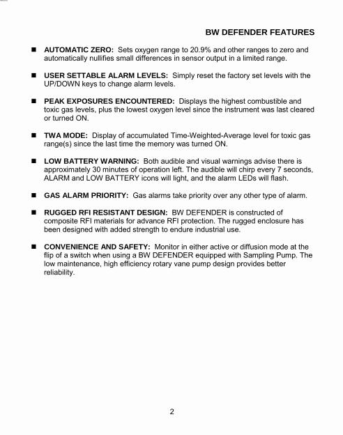
BW DEFENDER FEATURES ! AUTOMATIC ZERO: Sets oxygen range to 20.9% and other ranges to zero and
automatically nullifies small differences in sensor output in a limited range. ! USER SETTABLE ALARM LEVELS: Simply reset the factory set levels with the
UP/DOWN keys to change alarm levels. ! PEAK EXPOSURES ENCOUNTERED: Displays the highest combustible and
toxic gas levels, plus the lowest oxygen level since the instrument was last cleared or turned ON.
! TWA MODE: Display of accumulated Time-Weighted-Average level for toxic gas
range(s) since the last time the memory was turned ON. ! LOW BATTERY WARNING: Both audible and visual warnings advise there is
approximately 30 minutes of operation left. The audible will chirp every 7 seconds, ALARM and LOW BATTERY icons will light, and the alarm LEDs will flash.
! GAS ALARM PRIORITY: Gas alarms take priority over any other type of alarm. ! RUGGED RFI RESISTANT DESIGN: BW DEFENDER is constructed of
composite RFI materials for advance RFI protection. The rugged enclosure has been designed with added strength to endure industrial use.
! CONVENIENCE AND SAFETY: Monitor in either active or diffusion mode at the
flip of a switch when using a BW DEFENDER equipped with Sampling Pump. The low maintenance, high efficiency rotary vane pump design provides better reliability.
ACCESSORIES AND PARTS LIST ! BW DEFENDER ACCESSORIES
Part # DESCRIPTION D4-VP140 ............ 2-port vehicle 12 volt charger D4-2-LC ............... Leather carrying case with belt clip D4-2-EC ............... Hard-sided Equipment Carrying Case D4-E2358 ............ BW DEFENDER Earphone c/w sampling hose D4-SP01 .............. Motorized Sampling Pump c/w sampling hose D4-AS01 .............. Hand Aspirator Pump c/w sampling hose MM-PROB1 ......... 0.3 m (1 ft.) Search Probe c/w handle MM-PROB3 ......... 0.9 m (3 ft.) Search Probe c/w handle M1858 ................. Dilution Tube D4-UPGRADE1 ... 2 to 4 gas upgrade kit including D4-RHM04 sensor
! BW DEFENDER SPARE PARTS
D4-RHM04 ........... TWIN Toxic Sensor for CO and H2S c/w filter SR-X10 ................ O2 Sensor (2 year) c/w filter (compatible with: D4-2002; D2-2002 units only) D4-RX06 .............. O2 Sensor (1 year) c/w filter (compatible with: D4-2000; D2-2000 units only) D4-RW90 ............. Combustible Sensor M1758K ............... Toxic and Oxygen Sensor Replacement Screens (Kit of 10) D4-PF-1 ............... Particulate filter for Sampling hoses M1864K ............... Water trap filters for Sampling Pump D4-SP01 (Kit of 10) D4-WT-1 .............. In-line water trap for Aspirator Pump D4-HSP-10 .......... 3 m (10 ft.) Sampling Pump Hose D4-ASP-10 .......... 3 m (10 ft.) Aspirator Pump Hose M0931K ............... Quick connector spares for Sampling Pump (Kit of 2) M1812K ............... Quick connector spares for Aspirator Pump (Kit of 2) D4-VP100 ............ VERSAPAK 3.6 volt NiCad battery GA-VP110 ........... VERSAPAK 3.6 volt NiMH battery D4-VP135 ............ 2-port 110 VAC Charger Kit c/w VERSAPAK batteries D4-VP135-EU ...... 2-port 230 VAC Charger Kit - Continental European plug D4-VP135-UK ...... 2-port 230 VAC Charger Kit - UK/Ireland plug D4-M1725 ............ Break-away Wrist Strap D4-M1713 ............ Calibration Cup
33 2
Updated English D1218/3 P.2 Nov/00 (removed 2nd last bullet on Approvals) Nov/00 P.33 (2 year O2 sensor added and 1 year O2 sensor distinguished from 2 year; D4-VP160 removed; D4-1-LC changed to D4-2-LC –fits Schwartzer pump)
Page 6
SPECIFICATIONS DETECTOR: Multi-Gas with advanced microcontroller based operation Power: Rechargeable NiCad battery: Operation -12 hrs. ; Charge time - 3 hrs. Temp. Range: -20 to +50°C (-4 to +122°F) Humidity: 5 to 95 % RH non-condensing Self Test: Automatic when the BW DEFENDER is turned on Records/Displays: 1. TWA (Time Weighted Average) Exposure 2. Peak Exposures Calibration: Automatic Zero and Span Security: Password protection for calibration and alarm setpoints SENSORS: Combustible: Plug-in catalytic bead Toxics and Oxygen: Plug-in 2 year electrochemical cells DISPLAY: Four (4) extra-large gas specific alpha-numeric LCDs Alarm Setpoints: Displayed each time the unit is turned on Backlight: Pushbutton; Automatic in Alarm ALARMS: Audible: 90 dB @ 0.3 m (1 ft. ) variable pulsed beeper Visuals: 1. Two (2) flashing �sunbright� LEDs
2. Gas specific LCD flashes in alarm Levels: Two setpoints per sensor (user adjustable):
TOXICS: Low & High (TWA, STEL) OXYGEN: Deficiency (High) & Enrichment (Low) COMBUSTIBLES: Low & High
Other Alarms: Multiple Gas Exposure; Sensor Removed; Calibration Air; Low Battery Size: 11.9 x 10.3 x 2.9 cm (4.7 x 4.04 x 1.13 in.) (with Pump) 15.2 x 10.3 x 2.9 cm (6 x 4.04 x 1.13 in.) Weight: 375 g (13.27 oz.) including battery 424 g (14.85 oz.) including Pump & battery Enclosure: Rugged, composite material, RFI/EMI shielded SAMPLING PUMP: Powered by BW DEFENDER Switch: Activates Active Sampling or Diffusion Mode operation Active Mode: Fan ICON indicator Low Flow: Activates Alarms (both Audible and Visual) Flowrate: 300-350 ml/min with 3 m (10 ft.) hose and filters (dependent on pump) Input Pressure: 1.25 kPa Water Trap (built-in): Hydrophobic Teflon replaceable filter Current Draw: 75 mA Battery Life: Expected 8 hours (NiCad) SAMPLE HOSES: Tygon hose equipped with particulate filter and quick connect Length: Standard 3 m (10 ft.); maximum length 15 m (50 ft.) SAMPLE PROBES: 0.3, 0.9 or 1.8 m (1, 3 or 6 ft.) polycarbonate probes with handle and quick
connect
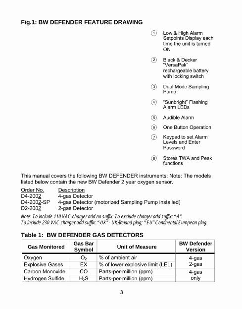
Fig.1: BW DEFENDER FEATURE DRAWING
A Low & High Alarm Setpoints Display each time the unit is turned ON
B Black & Decker �VersaPak� rechargeable battery with locking switch
C Dual Mode Sampling Pump
D �Sunbright� Flashing Alarm LEDs
E Audible Alarm
F One Button Operation
G Keypad to set Alarm Levels and Enter Password
H Stores TWA and Peak functions
This manual covers the following BW DEFENDER instruments: Note: The models listed below contain the new BW Defender 2 year oxygen sensor. Order No. Description D4-2002 4-gas Detector D4-2002-SP 4-gas Detector (motorized Sampling Pump installed) D2-2002 2-gas Detector Note: To include 110 VAC charger add no suffix. To exclude charger add suffix: “-A”. To include 230 VAC charger add suffix: “-UK” - UK/Ireland plug; “-EU” Continental European plug. Table 1: BW DEFENDER GAS DETECTORS
Gas Monitored Gas Bar Symbol Unit of Measure BW Defender
Version Oxygen O2 % of ambient air 4-gas
2-gas Explosive Gases EX % of lower explosive limit (LEL) Carbon Monoxide CO Parts-per-million (ppm) Hydrogen Sulfide H2S Parts-per-million (ppm)
4-gas only
3 32
Updated Nov, 2000 English D1218/3 Page 3 (models changed to D4-2002, D2-2002, to D4-2002-SP)
Page 7
GETTING STARTED POWER GENERAL: Familiarize yourself with all operating features and functions of the BW DEFENDER. The BW DEFENDER is calibrated at the factory. User selectable Alarm Setpoints have been set to relevant safety standards. The BW DEFENDER will advise the current Alarm Setpoints each time it is turned ON. If the user wishes to reset the Alarm Setpoints, refer to �ADJUSTING ALARM SETPOINTS�. BATTERY AND CHARGER: Batteries must be charged before use. WARNING: ONLY CHARGE BATTERIES USING A BLACK & DECKER
VERSAPAK™ CHARGER. DO NOT USE ANY OTHER CHARGER. FAILURE TO OBSERVE THIS PRECAUTION COULD LEAD TO FIRE OR EXPLOSION.
CAUTION: READ AND OBSERVE ALL INSTRUCTIONS AND PRECAUTIONS IN
THE BLACK & DECKER LITERATURE PROVIDED WITH THE BW DEFENDER. FAILURE TO DO SO MAY RESULT IN FIRE, ELECTRIC SHOCK OR OTHER FORMS OF PERSONAL INJURY OR PROPERTY DAMAGE.
FIRST TIME CHARGE: The charger supplied with the BW DEFENDER is a VAC
2-port charger, which requires approximately 6 hours (both batteries) for a first time charge.
NORMAL CHARGE TIME: After the first use, battery charging times decrease.
Normal charge time: 2-port VAC Charger - 3-4 hours for 1 to 2 batteries
Black & Decker VERSAPAK� chargers (other than the 2-port charger included with the BW DEFENDER) may be used with BW DEFENDER batteries. Refer to the instruction manual provided with the specific charger unit for charging instructions. NOTE: Batteries can be left in the VAC charger until required for use.
OPERATING SPECIFICATIONS
Operating Humidity: 15 to 90% Operating Pressure Range: Atmospheric ±10% Note 1: Response typically less than 2 seconds @ T50 Note 2: All performance data is based on conditions a 20°C (68°F), 50% RH and
1013 mBar (1 atm) CAUTION: The BW DEFENDER combustible sensor is highly poison resistant. All
catalytic sensors should be protected from exposure to lead compounds, silicones, chlorinated hydrocarbons. Certain organic vapors (e.g. leaded gasoline and halogenated hydrocarbons) may temporarily inhibit the sensor performance, in most cases it will recover after calibration.
Combustible EX
Oxygen Carbon Monoxide
Hydrogen Sulfide
Primary Sensitivity: %LEL % O2 CO ppm H2S ppm Measuring Range: 0-100% 0-25% 0-500 ppm 0-100 ppm
Maximum Overload: 30 % 1500 ppm 500 ppm
Detectable Accuracy: 1 % 0.1% 1 ppm 0.5 ppm
Response @ T50: ≤6 (Note 1) ≤2 ≤7 ≤5
Readout Increments: 1% 0.1% 5 ppm 1 ppm
Long Term Drift: Zero: (% signal loss/year) Span:
Nominal <5%
Nominal <5%
Nominal <5%
Nominal <5%
Sensor Warranty: 2 Years 2 Years 2 Years 2 Years
31 4
Updated English D1218/3 Nov/00 P31. (O2 warranty changes to 2 years) Nov/00 P4. (deleted D4-VP160 in three places)

Page 8
GETTING STARTED BATTERY GENERAL: For safety and ease of use, the battery is housed in an exterior separate battery compartment. You never have to open the monitor to change, or charge, the batteries. OPERATION: 12-13 hours on rechargeable NiCad
(8-8.5 hours with motorized Pump) WARNING: ONLY USE THE BLACK & DECKER VERSAPAK™ VP100 BATTERY
INSERTING THE BATTERY 1. Unlock the tan battery lock ring by
sliding it fully left.
2. Insert the battery (contact end first) into the unit until it is fully inserted.
3. Rotate battery lock ring from UNLOCKED to the LOCKED (fully right) position to hold the battery in place. The lock ring will click into place when it is fully sealed.
CAUTION: THE BATTERY LOCK RING MUST BE FULLY ENGAGED (CLICKED SHUT IN THE “LOCK” POSITION) BEFORE USE.
REMOVING THE BATTERY 1. Slide the battery lock ring to
UNLOCKED position (fully left) and pull the battery straight out.
WARNING: DO NOT REMOVE OR REPLACE THE BATTERY IN A HAZARDOUS AREA. DOING SO WILL IMPAIR THE INTRINSIC SAFETY OF THE UNIT, AND MAY LEAD TO FIRE OR EXPLOSION.
TROUBLESHOOTING
Problem Possible Cause Solution Unit intermittently enters alarm without apparent reason.
Ambient gas levels are near alarm point. Puff of gas. Alarms set incorrectly. Weak battery. Missing and/or faulty sensor. Pump unit is partially plugged.
Unit is operating normally. Use caution in suspect areas. Check maximum exposure reading. Reset alarm points. Replace and/or recharge battery. Replace sensor. Clear obstruction in pump hose.
Unit does not read zero when turned on.
Sensor has not had time to stabilize. Detector requires recalibration. Ambient gas is present.
Wait 60 seconds for sensor to stabilize. Recalibrate unit. Quick Calibration may be sufficient. Detector is operating properly. Use caution is suspect areas.
Unit does not accurately measure gas - display varies frequently - alarm sounds frequently. Alarm LEDs are dim and beeper is weak when unit enters alarm or self-test.
Sensor is missing. Battery is almost dead.
Replace sensor. Replace and/or recharge battery.
Unit shuts off without operator intervention. Display reads �BATTERY LOW�.
Automatic Shutdown feature has operated due to weak battery.
Replace and/or recharge battery.
Unit does not alarm when O2 sensor is removed.
Low (deficiency) alarm for O2 sensor - shut off by user.
Reset alarm point to correct value.
Unit does not alarm when explosive sensor is removed from unit.
High alarm for LEL sensor has been shut off.
Reset alarm point to correct value.
Unit displays �SE� in both H2S and CO displays; stays in alarm.
Toxic sensor is missing from the unit.
Replace toxic sensor or dummy toxic sensor (D2-2002 only) in 2-gas BW DEFENDER.
Pump does not run when attached to unit.
Pump is not turned on. Pump is plugged. Pump is defective.
Push vents closed to turn on pump. Clear hoses. Replace pump unit.
Unit will not auto zero or calibrate. O2 sensor reading is erratic.
O2 sensor replacement may not be compatible.
Change O2 sensor. D4-2002 2 year O2 (#SR-X10) D4-2000 1 year O2 (#SR-X10)
5 30
Updated Nov, 2000 English D1218/3 Page 30 (changed to D2-2002; Added last row for oxygen

Page 9
WRIST STRAP 1. Thread the split ring onto the silver
lanyard anchor located on the bottom back of the unit. Attach the strap to the split ring. The strap has a break away safety feature.
BW DEFENDER KEYPAD GENERAL: All operating features and functions are activated by the rubber keypad. The keypad operation is designed to prevent accidental activation of any function. The BW DEFENDER will advise you each time a function is accessed, and when automatic functions, are taking place. Press the keys down firmly. Each button has multiple functions, which are discussed in the appropriate sections of this manual.
TROUBLESHOOTING This section lists some common errors and their solutions. If you are unable to solve the problem, please contact BW Technologies for assistance.
Problem Possible Cause Solution Unit will not turn ON. No battery.
Battery is dead. Unit is damaged or defective.
Install battery. Replace and/or recharge battery. Contact BW.
Display doesn't show CO or H2S measurements.
This is a 2-gas version BW DEFENDER, which does not measure toxic gases.
Contact BW for kit to upgrade to the, 4-gas version (D4-2002).
Unit does not display TWA measurements.
This is a 2-gas version BW DEFENDER, which does not measure toxic gases.
Contact BW for kit to upgrade to the 4-gas version.
Unit does not enter alarm.
Alarm points are set incorrectly. Alarm setpoint(s) may be set to zero (off). Unit is in calibration mode.
Reset alarm setpoints to correct values. Reset alarm setpoints to correct values. Recalibrate unit immediately.
Unit enters alarm immediately when turned on.
Sensors are not yet stable. Battery warning alarm - battery is weak. Sampling pump is plugged. Sensor is missing from unit; or defective sensor.
Wait for 60 seconds. Replace/recharge battery. Remove obstruction. Replace sensor.
Unit does not respond to keypad.
Battery is dead. Unit is performing operations that require no user input.
Replace and/or recharge battery. Keypad operation will be automatically restored at the appropriate time.
Unit does not accurately measure gas.
Unit requires recalibration. Unit is colder/hotter than gas being measured. Sensor screens are clogged and dirty. Sensor(s) require(s) replacement. Sensor is missing from unit.
Recalibrate unit. Allow unit to acquire ambient temperature before use. Clean sensors. Replace sensor(s). Replace sensor.
Unit does not display maximum level of oxygen detected.
Peak detection for oxygen: displays the lowest value, not the highest value detected.
Unit is operating normally.
29 6

Page 10
GETTING STARTED DISPLAY ICONS GENERAL: BW DEFENDER icons and intelligent alpha-numeric display provide clear �Status at a Glance� advice at all times. Only applicable icons will be displayed at any one time. What the Various Icons Mean:
1) Alarm Icons: One or more of these icons will light up during an alarm condition: HIGH indicates high alarm; LOW indicates low alarm. Both HIGH and LOW are lit up during a Multiple Gas sensor alarm.
2) Gas Bar Icons: Identify the gas measured and the units of measure (ppm, %, and %LEL). Gases not being measured are not displayed.
3) Calibration Icons: Shown only when the unit is performing calibration operations.
4) Key Icon: Appears when calibration and alarm setpoint adjustment is password protected, or locked out. Also appears if the password is required from the user.
5) Up and Down Arrows: Appear when the unit is waiting for user input. This occurs during password entry and alarm setpoint entry.
6) Fan Icon: Indicates condition of the motorized sampling pump (if one is installed). The fan spins if pump is operational, and flashes when the pump is plugged.
7) Battery Icons: Continuously display the condition of the battery.
2-GAS to 4-GAS UPGRADE GENERAL: D4-2002 (4-gas) BW DEFENDERS � operating toxic gas sensor D2-2002 (2-gas) BW DEFENDERS � �dummy� sensor The Twin Toxic sensor can be added and the BW DEFENDER programming can be changed at any time to turn a 2-gas BW DEFENDER into a 4-gas BW DEFENDER. Upgrade a 2-gas to a 4-gas BW DEFENDER, do the following: 1. Turn the BW DEFENDER off. Remove the endcap. 2. Remove the middle �dummy� sensor and replace with a new BW DEFENDER
Twin Toxic sensor. Replace the endcap. 3. Press and hold the (ON/OFF) key. The detector will turn off. DO NOT
RELEASE THE ON/OFF KEY. 4. After 30 seconds, the BW DEFENDER will reactivate and emit one (1) or two (2)
beeps. The screen will light and the word OFF will appear on the screen. Release the button. The User Input prompt Icons will appear at the bottom of the screen.
If the BW DEFENDER beeps once: The BW DEFENDER is password protected. 5a. Enter the password by setting each of the three digits with the !UP, "DOWN
keys. Press TAB to advance to the next digit. If the password is incorrect, the LCD displays �NO�, and returns to normal operation. If the BW DEFENDER beeps twice, continue as described below.
If the BW DEFENDER beeps twice: 5b. Enter Field Option Code �777� using the !UP, "DOWN keys. Press the TAB key
to advance to the next digit, 6. After a pause, the unit beeps 3 times to confirm the entry was correct. Now enter
the Sensor Upgrade Code �001�. 7. After a pause, the BW DEFENDER will beep 4 times. Then the BW DEFENDER
will begin showing gas measurements for all 4 measured gases. The unit is now a 4-gas BW DEFENDER, capable of measuring toxic gases as well as LEL and O2.
WARNING 1: RECALIBRATE THE UNIT IMMEDIATELY AFTER PERFORMING THE UPGRADE. FAILURE TO DO SO WILL COMPROMISE THE BW DEFENDER'S EFFECTIVENESS AS A SAFETY INSTRUMENT.
WARNING 2: INCORRECTLY ENTERING THE FACTORY CODES 777 AND/OR 001 LISTED ABOVE MAY ERASE THE PASSWORD FROM THE BW DEFENDER. IF THIS HAPPENS, THE PASSWORD WILL HAVE TO BE MANUALLY SET. (See Page 21.)
7 28
Updated Nov, 2000 English D1218/3 Page 28 (models changed to D4-2002, D2-2002; last sentence changed to page 21)
7
Page 11
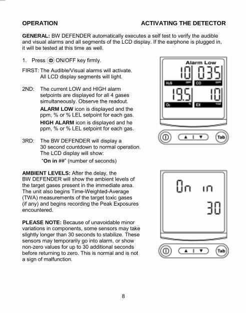
OPERATION ACTIVATING THE DETECTOR GENERAL: BW DEFENDER automatically executes a self test to verify the audible and visual alarms and all segments of the LCD display. If the earphone is plugged in, it will be tested at this time as well. 1. Press ON/OFF key firmly.
FIRST: The Audible/Visual alarms will activate. All LCD display segments will light.
2ND: The current LOW and HIGH alarm
setpoints are displayed for all 4 gases simultaneously. Observe the readout.
ALARM LOW icon is displayed and the ppm, % or % LEL setpoint for each gas.
HIGH ALARM icon is displayed and he ppm, % or % LEL setpoint for each gas.
3RD: The BW DEFENDER will display a
30 second countdown to normal operation. The LCD display will show:
�On in ##� (number of seconds) AMBIENT LEVELS: After the delay, the BW DEFENDER will show the ambient levels of the target gases present in the immediate area. The unit also begins Time-Weighted-Average (TWA) measurements of the target toxic gases (if any) and begins recording the Peak Exposures encountered. PLEASE NOTE: Because of unavoidable minor variations in components, some sensors may take slightly longer than 30 seconds to stabilize. These sensors may temporarily go into alarm, or show non-zero values for up to 30 additional seconds before returning to zero. This is normal and is not a sign of malfunction.
FIELD OPTIONS CONFIDENCE BEEP GENERAL: Once activated the Confidence Beep will BEEP once every 6 seconds to advise that it is operational.
IMPORTANT: As shown in the table below, the confidence beep option reverses the normal behavior of the BW DEFENDER low battery alarm. When the confidence beep is enabled, the BW DEFENDER will emit a short beep once every 6 seconds when the battery is okay. The BW DEFENDER will not beep when the battery is low.
Table 4: Confidence Beep Effect on Low Battery Alarm
To enable the confidence beep option, do the following: 1. Turn the BW DEFENDER ON. Wait until it is fully ON. 2. Press and hold the (ON/OFF) key. The detector will turn off. Continue to hold
the ON/OFF key�DO NOT RELEASE THE (ON/OFF) key. 3. After 30 seconds, the BW DEFENDER will reactivate and emit one or two beeps.
The screen will light and the word �OFF� (or �000�) will appear on the screen. Release the button. The User Input prompt Icons will appear at the bottom of the screen.
If the BW DEFENDER beeps once: (“000” appears) – Unit is password protected. 4a. Enter the current password by setting each of the 3 digits with the !UP/ "DOWN
keys. Press TAB after each digit. If the password is incorrect, the LCD will display �NO� and return to normal operation. If the BW DEFENDER beeps twice, continue as described below.
If the BW DEFENDER beeps twice (OFF appears): 4b. Enter the Field Option Code �777� using the !UP/ "DOWN keys. Press the TAB
key to advance to the next digit. 5. After a pause, the unit will beep 3 times to confirm the entry was correct. Now
enter the Confidence Beep Code �002�. 6. After a pause, the BW DEFENDER will beep 4 times to confirm acceptance. Once
this is complete, the BW DEFENDER will begin to emit the Confidence Beep and the unit will return to normal operation.
WARNING: INCORRECTLY ENTERING THE FIELD OPTION CODES 777 AND/OR 002 LISTED ABOVE MAY ERASE THE CURRENT PASSWORD FROM THE BW DEFENDER UNIT. IF THIS HAPPENS, THE PASSWORD WILL HAVE TO BE MANUALLY RESET. (See page 21.)
Confidence beep When battery is OK When battery is low Not Activated Battery alarm is Silent Battery alarm is Active Enabled Confidence Beep is Active Confidence Beep is Silent
27 8
Updated Nov, 2000 English D1218/3 Page 27 (last sentence changed to page 21)

Page 12
SENSOR REPLACEMENT GENERAL: The Twin Toxic, Oxygen and the Combustible sensors have a two (2) year warranty. Sensors should be replaced at the end of their warranty period. Replace dirty or plugged sensors immediately. Failure to do so may compromise the unit's effectiveness as a safety instrument. SENSOR PLACEMENT: With the LCD (front of the BW DEFENDER) facing you:
Oxygen Sensor (Black band) - Left hand side (nearest the battery) (2 year: # O2-A2) (1 year: # O2-A1) Twin Toxic Sensor (Turquoise band) - Middle Sensor Combustible Sensor (Silver sensor) - Right hand side
NOTE: Leave the shorting wire across the pins of the Twin Toxic sensor until just
before installation. 1. With the BW DEFENDER turned OFF, remove the 4 screws on the top endcap.
Remove the top endcap and the replaceable sensor screens.
2. Using a pair of needlenose pliers or similar tool, grasp the desired sensor firmly and pull straight out. Rocking the sensor back and forth gently may help free tightly held sensors. Do not use excessive force or sensors may be crushed.
3. Line up and insert the replacement sensor. It fits one way only. Push firmly into the mating sockets. Do not force into place. When fully seated, all sensors will be approximately the same height.
4. Replace the endcap and sensor screens with the 4 screws. Tighten the screws only slightly more than finger tight.
5. Turn the BW DEFENDER ON for 30 minutes and then calibrate the monitor. (See �CALIBRATION�.)
UPGRADING: 2-gas BW DEFENDERs may be upgraded to a 4-gas BW DEFENDER
in the field with the D4-UPGRADE1 Kit. SENSOR STORAGE: Sensors should be stored in a cool place (0 to 20°C
(32 to 68°F)). Keep in the sealed container they were shipped in.
DEACTIVATING THE DETECTOR GENERAL: The BW DEFENDER �OFF� function is designed to prevent accidental shut off, and will warn you that the BW DEFENDER is being shut down.
1. To deactivate, press the (ON/OFF) key firmly and hold it down until the word �OFF� appears on the screen (approximately 4 seconds).
OFF WARNING: Prior to the �OFF� readout the detector will emit 4 beeps and flash the alarm LEDs as a warning that the unit will be shutting down. Shut down will occur after the word �OFF� displays.
NOTE: If the button is released before 4 seconds have elapsed, the unit will not shut off. If this happens accidentally: Press the key again for 4 seconds.
BACKLIGHT DISPLAY Access the BW DEFENDER LCD backlight
feature to view the display in poor light. The backlight will remain lit for about 5 seconds, and then automatically shut off.
1. Press and release the TAB key. # The backlight is automatically activated if
any gas alarm condition exists.
NOTE: If the key is held down over 5 seconds, the TWA and Peak Exposure information will be displayed. (See �Accumulated Exposure Levels�.) The backlight will deactivate automatically after the TWA information is finished displaying.
Tab
9 26
Updated Nov, 2000 English D1218/3 Page 26 (take out one (1) year O2 warranty in first paragraph; distinguish 1 yr vs.2 yr.O2 sensor)
Page 13
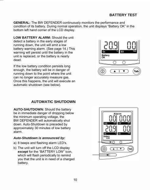
BATTERY TEST GENERAL: The BW DEFENDER continuously monitors the performance and condition of its battery. During normal operation, the unit displays �Battery OK� in the bottom left hand corner of the LCD display. LOW BATTERY ALARM: Should the unit detect a battery in the early stages of running down, the unit will emit a low battery warning alarm. (See page 14.) This warning will persist until the battery in the unit is replaced, or the battery is nearly dead.
If the low battery condition persists long enough, the battery will be in danger of running down to the point where the unit can no longer accurately measure gas. Once this happens, the unit will execute an automatic shutdown (see below).
AUTOMATIC SHUTDOWN AUTO-SHUTDOWN: Should the battery be in immediate danger of dropping below the minimum operating voltage, the BW DEFENDER will automatically shut down. Auto-Shutdown is preceded by approximately 30 minutes of low battery alarm.
Auto-Shutdown is announced by: a) 8 beeps and flashing alarm LED's. b) The unit will turn off the LCD display
except for the �BATTERY LOW� icon, which will flash periodically to remind you that the unit is in need of a charged battery.
25 10
Replaceable Sensor Screens #M1785

Page 14
ALARM SETPOINTS AUTO SPAN: BW DEFENDER will automatically adjust each responding sensor. First, a beep advises Auto Span has started. Then the �AUTO SPAN� and �Gas Bottle� icons will flash for 10 seconds. Apply the Test Gas before the end of the 10 second delay. 5. Attach hose to calibration cup. Place cup over the
sensors and open gas regulator valve fully (0.5 LPM). NOTE 1: The BW DEFENDER will scan for 30 seconds to check if Test Gas is being applied to any, or all, sensors. Real-time sensor readings will display on the LCD. If calibration gas is not detected by a sensor, it's LCD will flash and blank out for the duration of the Auto Span. (The previous calibration information is retained by the sensor.) NOTE 2: An audible sound advises that the AUTO SPAN has begun. Sensor Span Time: TWIN Toxic - 2 min.; Oxygen and Combustible - 15 seconds. WARNING: CALIBRATION GASES MUST FLOW UNTIL THE AUTO SPAN OPERATION IS COMPLETE, EVEN THOUGH THE LCD DISPLAYS MAY BE STABLE BEFORE THE SPAN OPERATION IS COMPLETED. 6. Three beeps announce AUTO SPAN has ended. Shut off and remove calibration
gas. Alarm setpoints will be displayed and may be adjusted if desired.
ADJUSTING ALARM SETPOINTS
1. The low alarm setpoint for the first available sensor is displayed on the LCD panel. Use the UP/DOWN arrow keys to adjust the alarm setpoint.
NOTE: Setting the alarm point to zero will disable affected alarm for that sensor. 2. Use the TAB key to advance to the next setpoint once the current one is
complete. Holding down the TAB key will advance the unit through the alarm setpoints quickly. Pressing no key causes the unit to automatically advance through the setpoints after a short delay.
3. Repeat steps 1) and 2) to set each sensor and alarm setpoint or skip all of the available alarm setpoints. After the last alarm setpoint has been set, there will be a short pause. The unit will then sound 4 beeps, and show “ACC” (Accept) on the LCD display. Calibration is now complete, and the unit will return to normal operation.
ACCUMULATED EXPOSURE LEVELS GENERAL: The 4-gas BW DEFENDER automatically calculates the TWA (Time-Weighted-Average). Exposure of H2S and CO (toxic) gases based on the standard 8 hour work day. The BW DEFENDER also records and displays the Peak Exposure encountered for each gas. These measurements are referred to as: �AE� = Average Exposure or TWA (Time-Weighted-Average) �PE� = Peak Exposure encountered (the maximum hazard)
To view: 1. Press and hold the key until the letters �AE� (or �PE�)
appear (5 sec.). NOTE 1: TWA measurements do not apply to oxygen or
explosive gases. The 2-gas BW DEFENDER skips directly to the �PE� peak readings.
TWA PPM READOUTS (4-gas BW DEFENDER) First: �AE� will appear, in both, H2S and CO displays, followed
by the TWA exposure readings in ppm for each gas.
PEAK HAZARD EXPOSURE READOUTS (2-gas and 4-gas BW DEFENDERS)
2ND: Next �PE� will appear on the displays followed by the Peak Exposure readings in ppm, % or % LEL for each gas monitored.
NOTE 2: For H2S, CO and EX, the Peak is the maximum exposure to gas encountered. For oxygen, the �Peak� hazard is actually the lowest oxygen deficiency level experienced.
DISPLAY BACKLIGHT: For easy reading in poor light, display backlight is lit.
3RD: The detector will return automatically to normal operation, displaying the gas present, and the backlight will turn OFF.
CAUTION: Accumulated exposures (TWA & PE) automatically reset when the BW DEFENDER is turned OFF. DO NOT turn the unit off during the workday, TWA and the Peak Exposure measurements will be reset.
11 24
Tab
Tab
Tab

Page 15
CALIBRATION GENERAL: The BW DEFENDER, designed for easy calibration, will automatically set span and zero. The LCD advises you as each automatic function takes place and when to apply calibration gas. IMPORTANT: BW DEFENDERMUST BE CALIBRATED USING GAS CONTAINING
CONCENTRATIONS OF TEST GASES THAT ARE EQUAL TO THE FOLLOWING PRESET VALUES: Hydrogen Sulfide - 25 ppm, Carbon Monoxide - 100 ppm, Methane (EX) - 2.5% (50% LEL), and Oxygen (O2) - 20.9%.
NOTE 1: BW DEFENDER Quad Gas is available from BW Technologies. If calibrating only 1, 2 or 3 sensors - the test gas concentrations must be equal to the above for the target sensor(s).
RECOMMEND: Calibrate every month depending on use and sensor exposure to poisons and contaminants.
WARNING: Do not calibrate a BW DEFENDER which is in Low Battery Alarm. Do not remove the Battery from the detector during calibration. Doing so will cause all NEW calibration information to be lost, leaving the old calibration settings.
1. Calibrate only in a clean, normal environment free of background gases. 2. Place a fully charged battery in the unit. Turn the BW DEFENDER on. Allow at
least two minutes for the sensors to stabilize. 3. To activate: Press and hold down both the and (ON and TAB) keys down
together until the word �CAL� appears on screen (4 seconds). The BW DEFENDER will beep and flash the alarm LEDs advising calibration is being initiated. As well, the icons for AUTO ZERO, AUTO SPAN and Gas Bottle are displayed.
NOTE 2: If BW DEFENDER is password protected, enter the password before �CAL� is displayed (See �Password Protection�).
4. AUTO ZERO: One beep will announce AUTO ZERO has begun. Gas specific LCDs will display zeroes. The AUTO ZERO icon will flash (approx. 5 seconds). The unit is now zeroed.
ALARM SETPOINTS GENERAL: Each gas detected has two user-settable alarm points. Each setpoint can be individually adjusted by the user. Each set of alarm setpoints control different as-pects of the BW DEFENDER'S behavior, as described below. Alarm setpoints can be password protected. NOTE: An alarm level can be disabled by setting that alarm setpoint to zero. TABLE 2: Alarm Setpoints Parameters and Factory Default Setpoints
Description of Sensor Alarm Setpoints
OXYGEN: The LOW alarm setpoint controls the one (1) Deficiency alarm, while the high alarm setpoint controls the one (1) Enrichment alarm. If the oxygen level drops below the LOW alarm setpoint, the unit will enter LOW alarm. If the oxy-gen level rises above the HIGH alarm setpoint, the unit will enter HIGH alarm.
Caution 1: It is not possible to set both alarms as deficiency alarms, or both alarms as enrichment alarms. Doing so will cause the unit to remain permanently in alarm until the alarm levels are reset.
EXPLOSIVE (Combustibles): The two alarm setpoints for the explosive gas sensor controls the level at which the unit enters LOW alarm and HIGH alarm.
TOXICS: For H2S and CO, the LOW alarm setpoints control both the instant LOW alarm level and the TWA (time-weighted-average) alarm level. When the LOW alarm setpoint is exceeded, the unit will enter LOW alarm. If the accumulated TWA level should exceed the LOW alarm setpoint, the unit will enter HIGH alarm.
Caution 2: The INSTANTANEOUS LOW alarm setpoint and the TWA alarm setpoint are identical. It is not possible to set the LOW alarm at one level, and TWA alarm at a different level. Setting the LOW alarm setpoint OFF will disable the TWA alarm. The toxic INSTANTANEOUS HIGH alarm setpoint controls the level at which the unit will enter HIGH alarm.
Gas Monitored Symbol Alarm Levels (EX: Factory default setpoints Low TWA High
Oxygen O2 Deficiency Enrichment 2&4-gas Explosive Gases EX (10% LEL) (20% LEL)
Carbon Monoxide CO (35 ppm) (35 ppm) (200 ppm) 4-gas Hydrogen Sulfide H2S (10 ppm) (10 ppm) (15 ppm)
Model
23 12
Tab

Page 16
AUDIBLE / VISUAL ALARMS GENERAL: Distinguish audibly and visually which gas hazard(s) is present, the alarm level(s) and type(s) of alarm: LOW, TWA, HIGH, or Multi-Gas alarm. During the different gas alarm pattern, the alarm LEDs blink on and off as the speaker sounds. The speaker tone changes from a low tone to a high tone in a repeating pattern. The backlight is on, and remains on for the duration of the alarm condition.
Table 3: Audible and Visual Alarms
LOW ALARM: Low alarm is activated when one of the detected gases has exceeded its low alarm setpoint.
HIGH ALARM: High alarm is activated when one of the detected gases has exceeded its high alarm setpoint.
Also, when the TWA (Time-Weighted-Average) exposure to a toxic gas exceeds the TWA alarm setpoint, High Alarm is activated.
NOTE: In TWA alarm, the affected toxic gas display(s) will blink even though the display may read �00�. To view Accumulated Exposures see page 11.
The Low and High Alarms stop when the ambient gas level returns to the acceptable range. MULTI-GAS ALARM: If more than one gas alarm hazard is present all alarm icons -HIGH ALARM LOW - will blink along with the LCDs of the affected gases. The audible will change from 1 Hz pattern to a 2 Hz pattern and back again. Thus, multiple-gas-alarm appears as a combination of both low and high alarm. CAUTION: If the combustible gas sensor is exposed to an over-range condition, the sensor will be latched at over-range until the BW Defender is shut off and turned back on again.
MAINTENANCE The rugged BW DEFENDER is designed to provide years of service with regular care and minimal maintenance. 1. Calibrate, test, and inspect the unit at regular intervals. 2. Keep an operations log of all events and occurrences. EXTERIOR: Clean the BW DEFENDER exterior with a soft damp cloth. Do not use
solvents, soaps, or polishes on the detector. DUST AND PARTICULATES: The Toxic and Oxygen sensors both have a
replaceable washable screen and a built-in washable screen. Without opening the instrument, clean the screens with a soft, clean brush, water and mild soap.
Caution: Replace dirty and/or plugged screens and sensors. NOTE: The combustible sensor has a sintered steel flame arrestor screen. Clean
only with a dry brush. WATER: Do not immerse in liquids. In the event the sensors become clogged by
water, clean immediately. Drain the sensors and dry with a clean cloth. Wait several minutes for them to air dry. Check that they are clean.
CAUTION: Removing the Twin Toxic sensor from the BW DEFENDER for longer
than 10 minutes may destabilize the sensor. If this occurs, replace the sensor in the board and turn on the BW DEFENDER for 30 minutes before using.
13 22
Indicator Low Alarm High and TWA Level Alarm
ICON flashes �ALARM �HIGH ALARM� Audible sounds at: Tone-Pattern
1 Hz Low to High -
2 Hz Low to High - faster
LEDs: Both flash in sync with the affected Gas Readout.
LCD Gas Display: Affected Gas Readout Blinks at 2 Hz. Backlight is lit.

Page 17
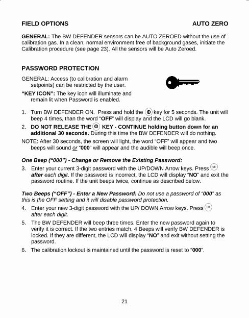
FIELD OPTIONS AUTO ZERO GENERAL: The BW DEFENDER sensors can be AUTO ZEROED without the use of calibration gas. In a clean, normal environment free of background gases, initiate the Calibration procedure (see page 23). All the sensors will be Auto Zeroed. PASSWORD PROTECTION GENERAL: Access (to calibration and alarm
setpoints) can be restricted by the user. “KEY ICON”: The key icon will illuminate and
remain lit when Password is enabled. 1. Turn BW DEFENDER ON. Press and hold the key for 5 seconds. The unit will
beep 4 times, than the word �OFF� will display and the LCD will go blank. 2. DO NOT RELEASE THE KEY - CONTINUE holding button down for an
additional 30 seconds. During this time the BW DEFENDER will do nothing. NOTE: After 30 seconds, the screen will light, the word �OFF� will appear and two
beeps will sound or �000� will appear and the audible will beep once. One Beep (“000”) - Change or Remove the Existing Password: 3. Enter your current 3-digit password with the UP/DOWN Arrow keys. Press
after each digit. If the password is incorrect, the LCD will display �NO� and exit the password routine. If the unit beeps twice, continue as described below.
Two Beeps (“OFF”) - Enter a New Password: Do not use a password of “000” as this is the OFF setting and it will disable password protection. 4. Enter your new 3-digit password with the UP/ DOWN Arrow keys. Press
after each digit. 5. The BW DEFENDER will beep three times. Enter the new password again to
verify it is correct. If the two entries match, 4 Beeps will verify BW DEFENDER is locked. If they are different, the LCD will display �NO� and exit without setting the password.
6. The calibration lockout is maintained until the password is reset to �000�.
OTHER ALARMS GENERAL: In addition to the gas hazard alarms, the BW DEFENDER provides a distinct alarm warning if the battery power is low, and to announce a missing sensor.
LOW BATTERY ALARM Occurs when the battery voltage falls to a point where the battery approximately 30 minutes of useful life remaining. Audible: Low-pitched �chirp� every 7 sec. LEDs: Blinks in sync with audible ICONS: �ALARM� word blinks every 2 sec. �LOW BATTERY� words blink in sync. The low battery warning persists until the battery recovers or, if the battery is in danger of failure, the BW DEFENDER will execute an Automatic Shutdown (see page 10). Observe carefully to ensure the battery does not fail without proper notification to the user. Caution: Low Battery Alarm is replaced if the Confidence Beep is activated. (See �Confidence Beep�.)
MISSING SENSOR ALARM Advises the detector is not intact and which sensor is missing. Twin Toxic Sensor: Activates a Multi-Gas type alarm and the letters �SE� (Sensor) will blink on both the CO and the H2S displays. This also applies if the �dummy sensor� is removed from the 2-gas version. Combustible Sensor: Activates high alarm audible and visuals and the letters �Or� (overrange) blink on the EX display. Oxygen Sensor: Activates low (Deficiency) alarm and the numbers �0.0� blink on O2 display.
21 14
Tab
Tab

Page 18
CONFINED SPACE The presence of a hazardous atmosphere is a major threat to workers in confined spaces. Special precautions are required - for workers who must enter a confined space - to protect workers from flammable or toxic atmospheres, oxygen depletion or enrichment. To reduce the hazard, it is required that the atmosphere be tested prior to entering the confined space. In addition to monitoring prior to entry, it is required that the atmosphere be constantly monitored during entry and as long as people are in the confined space. The BW DEFENDER is factory set to recommended alarm setpoints for: OSHA (Occupational Safety and Health Association), and OHS (Occupational Health and Safety) The first alarms are set: Combustibles: 10 % LEL
Oxygen: 19.5 % Vol. Carbon Monoxide: 35 ppm Hydrogen Sulfide: 10 ppm
BW DEFENDER alarm setpoints are field adjustable for special applications.
DAILY OPERATION 1. Turn your BW DEFENDER “ON”. All features and functions are activated. Leave
the BW DEFENDER ON for the entire work shift to collect TWA (Time Weighted Average) and PEAK Exposure data.
2. In the event of a hazardous gas alarm take appropriate precautions immediately. A gas alarm takes priority over any other types of alarms.
3. TEST ALARMS: Verify proper alarm function prior to use with BW’s “Bump” Alarm Test Gas. Alarm Test Gas is not intended to replace routine calibration, but rather to confirm proper alarm function between calibrations. Apply Test Gas. All sensors should be in alarm while the gas passes over the sen-sors. Check and confirm operation of: LEDs, Alarm Icons, Backlight, and Audible Alarm.
Note: Small quantity of gas required. DO NOT blast the sensors with “Bump” gas. CAUTION: Any rapid up-scale reading followed by a declining or erratic reading may
indicate a gas concentration beyond upper scale limit which may be hazardous.
CAUTION: High off-scale readings may indicate an explosive concentration.
15 20
Page 19
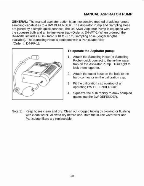
MANUAL ASPIRATOR PUMP GENERAL: The manual aspirator option is an inexpensive method of adding remote sampling capabilities to a BW DEFENDER . The Aspirator Pump and Sampling Hose are joined by a simple quick connect. The D4-AS01 Aspirator Pump is equipped with the squeeze bulb and an in-line water trap (Order #: D4-WT-1) When ordered, the D4-AS01 includes a D4-HAS-10 10 ft. (3.1m) sampling hose (longer lengths available). The Sampling Hose is equipped with a Particulate Filter (Order #: D4-PF-1).
To operate the Aspirator pump:
1. Attach the Sampling Hose (or Sampling Probe) quick connect to the in-line water trap on the Aspirator Pump. Turn right to lock them together.
2. Attach the outlet hose on the bulb to the barb connector on the calibration cap.
3. Fit the calibration cap overtop of an operating BW DEFENDER unit.
4. Squeeze the bulb rapidly to draw sampled gases into the BW DEFENDER.
Note 1: Keep hoses clean and dry. Clean out clogged tubing by blowing or flushing with clean water. Allow to dry before use. Both the in-line water filter and Particulate filters are replaceable.
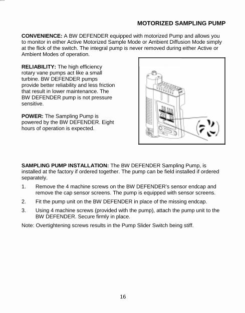
MOTORIZED SAMPLING PUMP CONVENIENCE: A BW DEFENDER equipped with motorized Pump and allows you to monitor in either Active Motorized Sample Mode or Ambient Diffusion Mode simply at the flick of the switch. The integral pump is never removed during either Active or Ambient Modes of operation. RELIABILITY: The high efficiency rotary vane pumps act like a small turbine. BW DEFENDER pumps provide better reliability and less friction that result in lower maintenance. The BW DEFENDER pump is not pressure sensitive. POWER: The Sampling Pump is powered by the BW DEFENDER. Eight hours of operation is expected. SAMPLING PUMP INSTALLATION: The BW DEFENDER Sampling Pump, is installed at the factory if ordered together. The pump can be field installed if ordered separately. 1. Remove the 4 machine screws on the BW DEFENDER’s sensor endcap and
remove the cap sensor screens. The pump is equipped with sensor screens. 2. Fit the pump unit on the BW DEFENDER in place of the missing endcap. 3. Using 4 machine screws (provided with the pump), attach the pump unit to the
BW DEFENDER. Secure firmly in place. Note: Overtightening screws results in the Pump Slider Switch being stiff.
19 16
Page 20
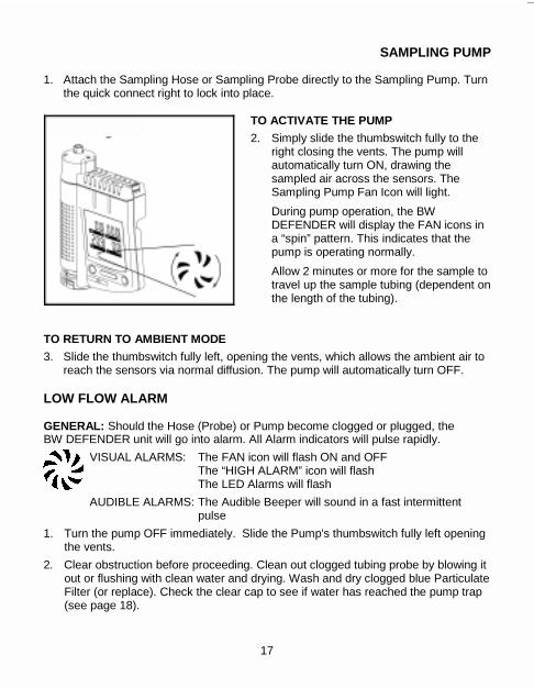
SAMPLING PUMP 1. Attach the Sampling Hose or Sampling Probe directly to the Sampling Pump. Turn
the quick connect right to lock into place. TO ACTIVATE THE PUMP 2. Simply slide the thumbswitch fully to the
right closing the vents. The pump will automatically turn ON, drawing the sampled air across the sensors. The Sampling Pump Fan Icon will light. During pump operation, the BW DEFENDER will display the FAN icons in a “spin” pattern. This indicates that the pump is operating normally. Allow 2 minutes or more for the sample to travel up the sample tubing (dependent on the length of the tubing).
TO RETURN TO AMBIENT MODE 3. Slide the thumbswitch fully left, opening the vents, which allows the ambient air to
reach the sensors via normal diffusion. The pump will automatically turn OFF. LOW FLOW ALARM GENERAL: Should the Hose (Probe) or Pump become clogged or plugged, the BW DEFENDER unit will go into alarm. All Alarm indicators will pulse rapidly.
VISUAL ALARMS: The FAN icon will flash ON and OFF The “HIGH ALARM” icon will flash The LED Alarms will flash
AUDIBLE ALARMS: The Audible Beeper will sound in a fast intermittent pulse
1. Turn the pump OFF immediately. Slide the Pump's thumbswitch fully left opening the vents.
2. Clear obstruction before proceeding. Clean out clogged tubing probe by blowing it out or flushing with clean water and drying. Wash and dry clogged blue Particulate Filter (or replace). Check the clear cap to see if water has reached the pump trap (see page 18).
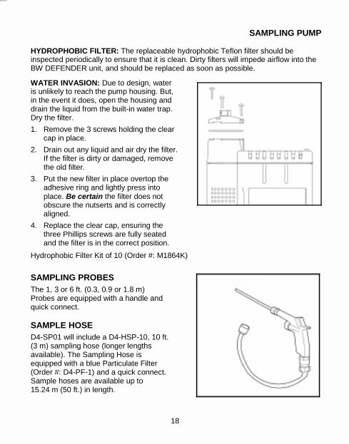
SAMPLING PUMP HYDROPHOBIC FILTER: The replaceable hydrophobic Teflon filter should be inspected periodically to ensure that it is clean. Dirty filters will impede airflow into the BW DEFENDER unit, and should be replaced as soon as possible.
WATER INVASION: Due to design, water is unlikely to reach the pump housing. But, in the event it does, open the housing and drain the liquid from the built-in water trap. Dry the filter. 1. Remove the 3 screws holding the clear
cap in place. 2. Drain out any liquid and air dry the filter.
If the filter is dirty or damaged, remove the old filter.
3. Put the new filter in place overtop the adhesive ring and lightly press into place. Be certain the filter does not obscure the nutserts and is correctly aligned.
4. Replace the clear cap, ensuring the three Phillips screws are fully seated and the filter is in the correct position.
Hydrophobic Filter Kit of 10 (Order #: M1864K)
SAMPLING PROBES The 1, 3 or 6 ft. (0.3, 0.9 or 1.8 m) Probes are equipped with a handle and quick connect. SAMPLE HOSE D4-SP01 will include a D4-HSP-10, 10 ft. (3 m) sampling hose (longer lengths available). The Sampling Hose is equipped with a blue Particulate Filter (Order #: D4-PF-1) and a quick connect. Sample hoses are available up to 15.24 m (50 ft.) in length.
17 18
Page 20
SAMPLING PUMP 1. Attach the Sampling Hose or Sampling Probe directly to the Sampling Pump. Turn
the quick connect right to lock into place. TO ACTIVATE THE PUMP 2. Simply slide the thumbswitch fully to the
right closing the vents. The pump will automatically turn ON, drawing the sampled air across the sensors. The Sampling Pump Fan Icon will light. During pump operation, the BW DEFENDER will display the FAN icons in a “spin” pattern. This indicates that the pump is operating normally. Allow 2 minutes or more for the sample to travel up the sample tubing (dependent on the length of the tubing).
TO RETURN TO AMBIENT MODE 3. Slide the thumbswitch fully left, opening the vents, which allows the ambient air to
reach the sensors via normal diffusion. The pump will automatically turn OFF. LOW FLOW ALARM GENERAL: Should the Hose (Probe) or Pump become clogged or plugged, the BW DEFENDER unit will go into alarm. All Alarm indicators will pulse rapidly.
VISUAL ALARMS: The FAN icon will flash ON and OFF The “HIGH ALARM” icon will flash The LED Alarms will flash
AUDIBLE ALARMS: The Audible Beeper will sound in a fast intermittent pulse
1. Turn the pump OFF immediately. Slide the Pump's thumbswitch fully left opening the vents.
2. Clear obstruction before proceeding. Clean out clogged tubing probe by blowing it out or flushing with clean water and drying. Wash and dry clogged blue Particulate Filter (or replace). Check the clear cap to see if water has reached the pump trap (see page 18).
SAMPLING PUMP HYDROPHOBIC FILTER: The replaceable hydrophobic Teflon filter should be inspected periodically to ensure that it is clean. Dirty filters will impede airflow into the BW DEFENDER unit, and should be replaced as soon as possible.
WATER INVASION: Due to design, water is unlikely to reach the pump housing. But, in the event it does, open the housing and drain the liquid from the built-in water trap. Dry the filter. 1. Remove the 3 screws holding the clear
cap in place. 2. Drain out any liquid and air dry the filter.
If the filter is dirty or damaged, remove the old filter.
3. Put the new filter in place overtop the adhesive ring and lightly press into place. Be certain the filter does not obscure the nutserts and is correctly aligned.
4. Replace the clear cap, ensuring the three Phillips screws are fully seated and the filter is in the correct position.
Hydrophobic Filter Kit of 10 (Order #: M1864K)
SAMPLING PROBES The 1, 3 or 6 ft. (0.3, 0.9 or 1.8 m) Probes are equipped with a handle and quick connect. SAMPLE HOSE D4-SP01 will include a D4-HSP-10, 10 ft. (3 m) sampling hose (longer lengths available). The Sampling Hose is equipped with a blue Particulate Filter (Order #: D4-PF-1) and a quick connect. Sample hoses are available up to 15.24 m (50 ft.) in length.
17 18
Page 19
MANUAL ASPIRATOR PUMP GENERAL: The manual aspirator option is an inexpensive method of adding remote sampling capabilities to a BW DEFENDER . The Aspirator Pump and Sampling Hose are joined by a simple quick connect. The D4-AS01 Aspirator Pump is equipped with the squeeze bulb and an in-line water trap (Order #: D4-WT-1) When ordered, the D4-AS01 includes a D4-HAS-10 10 ft. (3.1m) sampling hose (longer lengths available). The Sampling Hose is equipped with a Particulate Filter (Order #: D4-PF-1).
To operate the Aspirator pump:
1. Attach the Sampling Hose (or Sampling Probe) quick connect to the in-line water trap on the Aspirator Pump. Turn right to lock them together.
2. Attach the outlet hose on the bulb to the barb connector on the calibration cap.
3. Fit the calibration cap overtop of an operating BW DEFENDER unit.
4. Squeeze the bulb rapidly to draw sampled gases into the BW DEFENDER.
Note 1: Keep hoses clean and dry. Clean out clogged tubing by blowing or flushing with clean water. Allow to dry before use. Both the in-line water filter and Particulate filters are replaceable.
MOTORIZED SAMPLING PUMP CONVENIENCE: A BW DEFENDER equipped with motorized Pump and allows you to monitor in either Active Motorized Sample Mode or Ambient Diffusion Mode simply at the flick of the switch. The integral pump is never removed during either Active or Ambient Modes of operation. RELIABILITY: The high efficiency rotary vane pumps act like a small turbine. BW DEFENDER pumps provide better reliability and less friction that result in lower maintenance. The BW DEFENDER pump is not pressure sensitive. POWER: The Sampling Pump is powered by the BW DEFENDER. Eight hours of operation is expected. SAMPLING PUMP INSTALLATION: The BW DEFENDER Sampling Pump, is installed at the factory if ordered together. The pump can be field installed if ordered separately. 1. Remove the 4 machine screws on the BW DEFENDER’s sensor endcap and
remove the cap sensor screens. The pump is equipped with sensor screens. 2. Fit the pump unit on the BW DEFENDER in place of the missing endcap. 3. Using 4 machine screws (provided with the pump), attach the pump unit to the
BW DEFENDER. Secure firmly in place. Note: Overtightening screws results in the Pump Slider Switch being stiff.
19 16
Page 18
CONFINED SPACE The presence of a hazardous atmosphere is a major threat to workers in confined spaces. Special precautions are required - for workers who must enter a confined space - to protect workers from flammable or toxic atmospheres, oxygen depletion or enrichment. To reduce the hazard, it is required that the atmosphere be tested prior to entering the confined space. In addition to monitoring prior to entry, it is required that the atmosphere be constantly monitored during entry and as long as people are in the confined space. The BW DEFENDER is factory set to recommended alarm setpoints for: OSHA (Occupational Safety and Health Association), and OHS (Occupational Health and Safety) The first alarms are set: Combustibles: 10 % LEL
Oxygen: 19.5 % Vol. Carbon Monoxide: 35 ppm Hydrogen Sulfide: 10 ppm
BW DEFENDER alarm setpoints are field adjustable for special applications.
DAILY OPERATION 1. Turn your BW DEFENDER “ON”. All features and functions are activated. Leave
the BW DEFENDER ON for the entire work shift to collect TWA (Time Weighted Average) and PEAK Exposure data.
2. In the event of a hazardous gas alarm take appropriate precautions immediately. A gas alarm takes priority over any other types of alarms.
3. TEST ALARMS: Verify proper alarm function prior to use with BW’s “Bump” Alarm Test Gas. Alarm Test Gas is not intended to replace routine calibration, but rather to confirm proper alarm function between calibrations. Apply Test Gas. All sensors should be in alarm while the gas passes over the sen-sors. Check and confirm operation of: LEDs, Alarm Icons, Backlight, and Audible Alarm.
Note: Small quantity of gas required. DO NOT blast the sensors with “Bump” gas. CAUTION: Any rapid up-scale reading followed by a declining or erratic reading may
indicate a gas concentration beyond upper scale limit which may be hazardous.
CAUTION: High off-scale readings may indicate an explosive concentration.
15 20
Page 17
FIELD OPTIONS AUTO ZERO GENERAL: The BW DEFENDER sensors can be AUTO ZEROED without the use of calibration gas. In a clean, normal environment free of background gases, initiate the Calibration procedure (see page 23). All the sensors will be Auto Zeroed. PASSWORD PROTECTION GENERAL: Access (to calibration and alarm
setpoints) can be restricted by the user. “KEY ICON”: The key icon will illuminate and
remain lit when Password is enabled. 1. Turn BW DEFENDER ON. Press and hold the key for 5 seconds. The unit will
beep 4 times, than the word “OFF” will display and the LCD will go blank. 2. DO NOT RELEASE THE KEY - CONTINUE holding button down for an
additional 30 seconds. During this time the BW DEFENDER will do nothing. NOTE: After 30 seconds, the screen will light, the word “OFF” will appear and two
beeps will sound or “000” will appear and the audible will beep once. One Beep (“000”) - Change or Remove the Existing Password: 3. Enter your current 3-digit password with the UP/DOWN Arrow keys. Press
after each digit. If the password is incorrect, the LCD will display “NO” and exit the password routine. If the unit beeps twice, continue as described below.
Two Beeps (“OFF”) - Enter a New Password: Do not use a password of “000” as this is the OFF setting and it will disable password protection. 4. Enter your new 3-digit password with the UP/ DOWN Arrow keys. Press
after each digit. 5. The BW DEFENDER will beep three times. Enter the new password again to
verify it is correct. If the two entries match, 4 Beeps will verify BW DEFENDER is locked. If they are different, the LCD will display “NO” and exit without setting the password.
6. The calibration lockout is maintained until the password is reset to “000”.
OTHER ALARMS GENERAL: In addition to the gas hazard alarms, the BW DEFENDER provides a distinct alarm warning if the battery power is low, and to announce a missing sensor.
LOW BATTERY ALARM Occurs when the battery voltage falls to a point where the battery approximately 30 minutes of useful life remaining. Audible: Low-pitched “chirp” every 7 sec. LEDs: Blinks in sync with audible ICONS: “ALARM” word blinks every 2 sec. “LOW BATTERY” words blink in sync. The low battery warning persists until the battery recovers or, if the battery is in danger of failure, the BW DEFENDER will execute an Automatic Shutdown (see page 10). Observe carefully to ensure the battery does not fail without proper notification to the user. Caution: Low Battery Alarm is replaced if the Confidence Beep is activated. (See “Confidence Beep”.)
MISSING SENSOR ALARM Advises the detector is not intact and which sensor is missing. Twin Toxic Sensor: Activates a Multi-Gas type alarm and the letters “SE” (Sensor) will blink on both the CO and the H2S displays. This also applies if the “dummy sensor” is removed from the 2-gas version. Combustible Sensor: Activates high alarm audible and visuals and the letters “Or” (overrange) blink on the EX display. Oxygen Sensor: Activates low (Deficiency) alarm and the numbers “0.0” blink on O2 display.
21 14
Tab
Tab

Page 16
AUDIBLE / VISUAL ALARMS GENERAL: Distinguish audibly and visually which gas hazard(s) is present, the alarm level(s) and type(s) of alarm: LOW, TWA, HIGH, or Multi-Gas alarm. During the different gas alarm pattern, the alarm LEDs blink on and off as the speaker sounds. The speaker tone changes from a low tone to a high tone in a repeating pattern. The backlight is on, and remains on for the duration of the alarm condition.
Table 3: Audible and Visual Alarms
LOW ALARM: Low alarm is activated when one of the detected gases has exceeded its low alarm setpoint.
HIGH ALARM: High alarm is activated when one of the detected gases has exceeded its high alarm setpoint.
Also, when the TWA (Time-Weighted-Average) exposure to a toxic gas exceeds the TWA alarm setpoint, High Alarm is activated.
NOTE: In TWA alarm, the affected toxic gas display(s) will blink even though the display may read �00�. To view Accumulated Exposures see page 11.
The Low and High Alarms stop when the ambient gas level returns to the acceptable range. MULTI-GAS ALARM: If more than one gas alarm hazard is present all alarm icons -HIGH ALARM LOW - will blink along with the LCDs of the affected gases. The audible will change from 1 Hz pattern to a 2 Hz pattern and back again. Thus, multiple-gas-alarm appears as a combination of both low and high alarm. CAUTION: If the combustible gas sensor is exposed to an over-range condition, the sensor will be latched at over-range until the BW Defender is shut off and turned back on again.
MAINTENANCE The rugged BW DEFENDER is designed to provide years of service with regular care and minimal maintenance. 1. Calibrate, test, and inspect the unit at regular intervals. 2. Keep an operations log of all events and occurrences. EXTERIOR: Clean the BW DEFENDER exterior with a soft damp cloth. Do not use
solvents, soaps, or polishes on the detector. DUST AND PARTICULATES: The Toxic and Oxygen sensors both have a
replaceable washable screen and a built-in washable screen. Without opening the instrument, clean the screens with a soft, clean brush, water and mild soap.
Caution: Replace dirty and/or plugged screens and sensors. NOTE: The combustible sensor has a sintered steel flame arrestor screen. Clean
only with a dry brush. WATER: Do not immerse in liquids. In the event the sensors become clogged by
water, clean immediately. Drain the sensors and dry with a clean cloth. Wait several minutes for them to air dry. Check that they are clean.
CAUTION: Removing the Twin Toxic sensor from the BW DEFENDER for longer
than 10 minutes may destabilize the sensor. If this occurs, replace the sensor in the board and turn on the BW DEFENDER for 30 minutes before using.
13 22
Indicator Low Alarm High and TWA Level Alarm
ICON flashes �ALARM �HIGH ALARM� Audible sounds at: Tone-Pattern
1 Hz Low to High -
2 Hz Low to High - faster
LEDs: Both flash in sync with the affected Gas Readout.
LCD Gas Display: Affected Gas Readout Blinks at 2 Hz. Backlight is lit.

Page 15
CALIBRATION GENERAL: The BW DEFENDER, designed for easy calibration, will automatically set span and zero. The LCD advises you as each automatic function takes place and when to apply calibration gas. IMPORTANT: BW DEFENDERMUST BE CALIBRATED USING GAS CONTAINING
CONCENTRATIONS OF TEST GASES THAT ARE EQUAL TO THE FOLLOWING PRESET VALUES: Hydrogen Sulfide - 25 ppm, Carbon Monoxide - 100 ppm, Methane (EX) - 2.5% (50% LEL), and Oxygen (O2) - 20.9%.
NOTE 1: BW DEFENDER Quad Gas is available from BW Technologies. If calibrating only 1, 2 or 3 sensors - the test gas concentrations must be equal to the above for the target sensor(s).
RECOMMEND: Calibrate every month depending on use and sensor exposure to poisons and contaminants.
WARNING: Do not calibrate a BW DEFENDER which is in Low Battery Alarm. Do not remove the Battery from the detector during calibration. Doing so will cause all NEW calibration information to be lost, leaving the old calibration settings.
1. Calibrate only in a clean, normal environment free of background gases. 2. Place a fully charged battery in the unit. Turn the BW DEFENDER on. Allow at
least two minutes for the sensors to stabilize. 3. To activate: Press and hold down both the and (ON and TAB) keys down
together until the word “CAL” appears on screen (4 seconds). The BW DEFENDER will beep and flash the alarm LEDs advising calibration is being initiated. As well, the icons for AUTO ZERO, AUTO SPAN and Gas Bottle are displayed.
NOTE 2: If BW DEFENDER is password protected, enter the password before “CAL” is displayed (See “Password Protection”).
4. AUTO ZERO: One beep will announce AUTO ZERO has begun. Gas specific LCDs will display zeroes. The AUTO ZERO icon will flash (approx. 5 seconds). The unit is now zeroed.
ALARM SETPOINTS GENERAL: Each gas detected has two user-settable alarm points. Each setpoint can be individually adjusted by the user. Each set of alarm setpoints control different as-pects of the BW DEFENDER'S behavior, as described below. Alarm setpoints can be password protected. NOTE: An alarm level can be disabled by setting that alarm setpoint to zero. TABLE 2: Alarm Setpoints Parameters and Factory Default Setpoints
Description of Sensor Alarm Setpoints
OXYGEN: The LOW alarm setpoint controls the one (1) Deficiency alarm, while the high alarm setpoint controls the one (1) Enrichment alarm. If the oxygen level drops below the LOW alarm setpoint, the unit will enter LOW alarm. If the oxy-gen level rises above the HIGH alarm setpoint, the unit will enter HIGH alarm.
Caution 1: It is not possible to set both alarms as deficiency alarms, or both alarms as enrichment alarms. Doing so will cause the unit to remain permanently in alarm until the alarm levels are reset.
EXPLOSIVE (Combustibles): The two alarm setpoints for the explosive gas sensor controls the level at which the unit enters LOW alarm and HIGH alarm.
TOXICS: For H2S and CO, the LOW alarm setpoints control both the instant LOW alarm level and the TWA (time-weighted-average) alarm level. When the LOW alarm setpoint is exceeded, the unit will enter LOW alarm. If the accumulated TWA level should exceed the LOW alarm setpoint, the unit will enter HIGH alarm.
Caution 2: The INSTANTANEOUS LOW alarm setpoint and the TWA alarm setpoint are identical. It is not possible to set the LOW alarm at one level, and TWA alarm at a different level. Setting the LOW alarm setpoint OFF will disable the TWA alarm. The toxic INSTANTANEOUS HIGH alarm setpoint controls the level at which the unit will enter HIGH alarm.
Gas Monitored Symbol Alarm Levels (EX: Factory default setpoints Low TWA High
Oxygen O2 Deficiency Enrichment 2&4-gas Explosive Gases EX (10% LEL) (20% LEL)
Carbon Monoxide CO (35 ppm) (35 ppm) (200 ppm) 4-gas Hydrogen Sulfide H2S (10 ppm) (10 ppm) (15 ppm)
Model
23 12
Tab
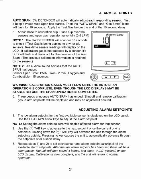
Page 14
ALARM SETPOINTS AUTO SPAN: BW DEFENDER will automatically adjust each responding sensor. First, a beep advises Auto Span has started. Then the �AUTO SPAN� and �Gas Bottle� icons will flash for 10 seconds. Apply the Test Gas before the end of the 10 second delay. 5. Attach hose to calibration cup. Place cup over the
sensors and open gas regulator valve fully (0.5 LPM). NOTE 1: The BW DEFENDER will scan for 30 seconds to check if Test Gas is being applied to any, or all, sensors. Real-time sensor readings will display on the LCD. If calibration gas is not detected by a sensor, it's LCD will flash and blank out for the duration of the Auto Span. (The previous calibration information is retained by the sensor.) NOTE 2: An audible sound advises that the AUTO SPAN has begun. Sensor Span Time: TWIN Toxic - 2 min.; Oxygen and Combustible - 15 seconds. WARNING: CALIBRATION GASES MUST FLOW UNTIL THE AUTO SPAN OPERATION IS COMPLETE, EVEN THOUGH THE LCD DISPLAYS MAY BE STABLE BEFORE THE SPAN OPERATION IS COMPLETED. 6. Three beeps announce AUTO SPAN has ended. Shut off and remove calibration
gas. Alarm setpoints will be displayed and may be adjusted if desired.
ADJUSTING ALARM SETPOINTS
1. The low alarm setpoint for the first available sensor is displayed on the LCD panel. Use the UP/DOWN arrow keys to adjust the alarm setpoint.
NOTE: Setting the alarm point to zero will disable affected alarm for that sensor. 2. Use the TAB key to advance to the next setpoint once the current one is
complete. Holding down the TAB key will advance the unit through the alarm setpoints quickly. Pressing no key causes the unit to automatically advance through the setpoints after a short delay.
3. Repeat steps 1) and 2) to set each sensor and alarm setpoint or skip all of the available alarm setpoints. After the last alarm setpoint has been set, there will be a short pause. The unit will then sound 4 beeps, and show “ACC” (Accept) on the LCD display. Calibration is now complete, and the unit will return to normal operation.
ACCUMULATED EXPOSURE LEVELS GENERAL: The 4-gas BW DEFENDER automatically calculates the TWA (Time-Weighted-Average). Exposure of H2S and CO (toxic) gases based on the standard 8 hour work day. The BW DEFENDER also records and displays the Peak Exposure encountered for each gas. These measurements are referred to as: �AE� = Average Exposure or TWA (Time-Weighted-Average) �PE� = Peak Exposure encountered (the maximum hazard)
To view: 1. Press and hold the key until the letters �AE� (or �PE�)
appear (5 sec.). NOTE 1: TWA measurements do not apply to oxygen or
explosive gases. The 2-gas BW DEFENDER skips directly to the �PE� peak readings.
TWA PPM READOUTS (4-gas BW DEFENDER) First: �AE� will appear, in both, H2S and CO displays, followed
by the TWA exposure readings in ppm for each gas.
PEAK HAZARD EXPOSURE READOUTS (2-gas and 4-gas BW DEFENDERS)
2ND: Next �PE� will appear on the displays followed by the Peak Exposure readings in ppm, % or % LEL for each gas monitored.
NOTE 2: For H2S, CO and EX, the Peak is the maximum exposure to gas encountered. For oxygen, the �Peak� hazard is actually the lowest oxygen deficiency level experienced.
DISPLAY BACKLIGHT: For easy reading in poor light, display backlight is lit.
3RD: The detector will return automatically to normal operation, displaying the gas present, and the backlight will turn OFF.
CAUTION: Accumulated exposures (TWA & PE) automatically reset when the BW DEFENDER is turned OFF. DO NOT turn the unit off during the workday, TWA and the Peak Exposure measurements will be reset.
11 24
Tab
Tab
Tab

Page 13
BATTERY TEST GENERAL: The BW DEFENDER continuously monitors the performance and condition of its battery. During normal operation, the unit displays “Battery OK” in the bottom left hand corner of the LCD display. LOW BATTERY ALARM: Should the unit detect a battery in the early stages of running down, the unit will emit a low battery warning alarm. (See page 14.) This warning will persist until the battery in the unit is replaced, or the battery is nearly dead.
If the low battery condition persists long enough, the battery will be in danger of running down to the point where the unit can no longer accurately measure gas. Once this happens, the unit will execute an automatic shutdown (see below).
AUTOMATIC SHUTDOWN AUTO-SHUTDOWN: Should the battery be in immediate danger of dropping below the minimum operating voltage, the BW DEFENDER will automatically shut down. Auto-Shutdown is preceded by approximately 30 minutes of low battery alarm.
Auto-Shutdown is announced by: a) 8 beeps and flashing alarm LED's. b) The unit will turn off the LCD display
except for the “BATTERY LOW” icon, which will flash periodically to remind you that the unit is in need of a charged battery.
25 10
Replaceable Sensor Screens #M1785
Page 12
SENSOR REPLACEMENT GENERAL: The Twin Toxic, Oxygen and the Combustible sensors have a two (2) year warranty. Sensors should be replaced at the end of their warranty period. Replace dirty or plugged sensors immediately. Failure to do so may compromise the unit's effectiveness as a safety instrument. SENSOR PLACEMENT: With the LCD (front of the BW DEFENDER) facing you:
Oxygen Sensor (Black band) - Left hand side (nearest the battery) (2 year: # O2-A2) (1 year: # O2-A1) Twin Toxic Sensor (Turquoise band) - Middle Sensor Combustible Sensor (Silver sensor) - Right hand side
NOTE: Leave the shorting wire across the pins of the Twin Toxic sensor until just
before installation. 1. With the BW DEFENDER turned OFF, remove the 4 screws on the top endcap.
Remove the top endcap and the replaceable sensor screens.
2. Using a pair of needlenose pliers or similar tool, grasp the desired sensor firmly and pull straight out. Rocking the sensor back and forth gently may help free tightly held sensors. Do not use excessive force or sensors may be crushed.
3. Line up and insert the replacement sensor. It fits one way only. Push firmly into the mating sockets. Do not force into place. When fully seated, all sensors will be approximately the same height.
4. Replace the endcap and sensor screens with the 4 screws. Tighten the screws only slightly more than finger tight.
5. Turn the BW DEFENDER ON for 30 minutes and then calibrate the monitor. (See �CALIBRATION�.)
UPGRADING: 2-gas BW DEFENDERs may be upgraded to a 4-gas BW DEFENDER
in the field with the D4-UPGRADE1 Kit. SENSOR STORAGE: Sensors should be stored in a cool place (0 to 20°C
(32 to 68°F)). Keep in the sealed container they were shipped in.
DEACTIVATING THE DETECTOR GENERAL: The BW DEFENDER �OFF� function is designed to prevent accidental shut off, and will warn you that the BW DEFENDER is being shut down.
1. To deactivate, press the (ON/OFF) key firmly and hold it down until the word �OFF� appears on the screen (approximately 4 seconds).
OFF WARNING: Prior to the �OFF� readout the detector will emit 4 beeps and flash the alarm LEDs as a warning that the unit will be shutting down. Shut down will occur after the word �OFF� displays.
NOTE: If the button is released before 4 seconds have elapsed, the unit will not shut off. If this happens accidentally: Press the key again for 4 seconds.
BACKLIGHT DISPLAY Access the BW DEFENDER LCD backlight
feature to view the display in poor light. The backlight will remain lit for about 5 seconds, and then automatically shut off.
1. Press and release the TAB key. # The backlight is automatically activated if
any gas alarm condition exists.
NOTE: If the key is held down over 5 seconds, the TWA and Peak Exposure information will be displayed. (See �Accumulated Exposure Levels�.) The backlight will deactivate automatically after the TWA information is finished displaying.
Tab
9 26
Updated Nov, 2000 English D1218/3 Page 26 (take out one (1) year O2 warranty in first paragraph; distinguish 1 yr vs.2 yr.O2 sensor)
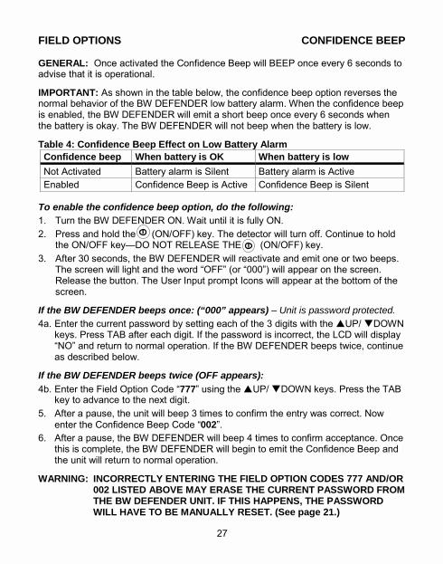
Page 11
OPERATION ACTIVATING THE DETECTOR GENERAL: BW DEFENDER automatically executes a self test to verify the audible and visual alarms and all segments of the LCD display. If the earphone is plugged in, it will be tested at this time as well. 1. Press ON/OFF key firmly.
FIRST: The Audible/Visual alarms will activate. All LCD display segments will light.
2ND: The current LOW and HIGH alarm
setpoints are displayed for all 4 gases simultaneously. Observe the readout.
ALARM LOW icon is displayed and the ppm, % or % LEL setpoint for each gas.
HIGH ALARM icon is displayed and he ppm, % or % LEL setpoint for each gas.
3RD: The BW DEFENDER will display a
30 second countdown to normal operation. The LCD display will show:
�On in ##� (number of seconds) AMBIENT LEVELS: After the delay, the BW DEFENDER will show the ambient levels of the target gases present in the immediate area. The unit also begins Time-Weighted-Average (TWA) measurements of the target toxic gases (if any) and begins recording the Peak Exposures encountered. PLEASE NOTE: Because of unavoidable minor variations in components, some sensors may take slightly longer than 30 seconds to stabilize. These sensors may temporarily go into alarm, or show non-zero values for up to 30 additional seconds before returning to zero. This is normal and is not a sign of malfunction.
FIELD OPTIONS CONFIDENCE BEEP GENERAL: Once activated the Confidence Beep will BEEP once every 6 seconds to advise that it is operational.
IMPORTANT: As shown in the table below, the confidence beep option reverses the normal behavior of the BW DEFENDER low battery alarm. When the confidence beep is enabled, the BW DEFENDER will emit a short beep once every 6 seconds when the battery is okay. The BW DEFENDER will not beep when the battery is low.
Table 4: Confidence Beep Effect on Low Battery Alarm
To enable the confidence beep option, do the following: 1. Turn the BW DEFENDER ON. Wait until it is fully ON. 2. Press and hold the (ON/OFF) key. The detector will turn off. Continue to hold
the ON/OFF key�DO NOT RELEASE THE (ON/OFF) key. 3. After 30 seconds, the BW DEFENDER will reactivate and emit one or two beeps.
The screen will light and the word �OFF� (or �000�) will appear on the screen. Release the button. The User Input prompt Icons will appear at the bottom of the screen.
If the BW DEFENDER beeps once: (“000” appears) – Unit is password protected. 4a. Enter the current password by setting each of the 3 digits with the !UP/ "DOWN
keys. Press TAB after each digit. If the password is incorrect, the LCD will display �NO� and return to normal operation. If the BW DEFENDER beeps twice, continue as described below.
If the BW DEFENDER beeps twice (OFF appears): 4b. Enter the Field Option Code �777� using the !UP/ "DOWN keys. Press the TAB
key to advance to the next digit. 5. After a pause, the unit will beep 3 times to confirm the entry was correct. Now
enter the Confidence Beep Code �002�. 6. After a pause, the BW DEFENDER will beep 4 times to confirm acceptance. Once
this is complete, the BW DEFENDER will begin to emit the Confidence Beep and the unit will return to normal operation.
WARNING: INCORRECTLY ENTERING THE FIELD OPTION CODES 777 AND/OR 002 LISTED ABOVE MAY ERASE THE CURRENT PASSWORD FROM THE BW DEFENDER UNIT. IF THIS HAPPENS, THE PASSWORD WILL HAVE TO BE MANUALLY RESET. (See page 21.)
Confidence beep When battery is OK When battery is low Not Activated Battery alarm is Silent Battery alarm is Active Enabled Confidence Beep is Active Confidence Beep is Silent
27 8
Updated Nov, 2000 English D1218/3 Page 27 (last sentence changed to page 21)
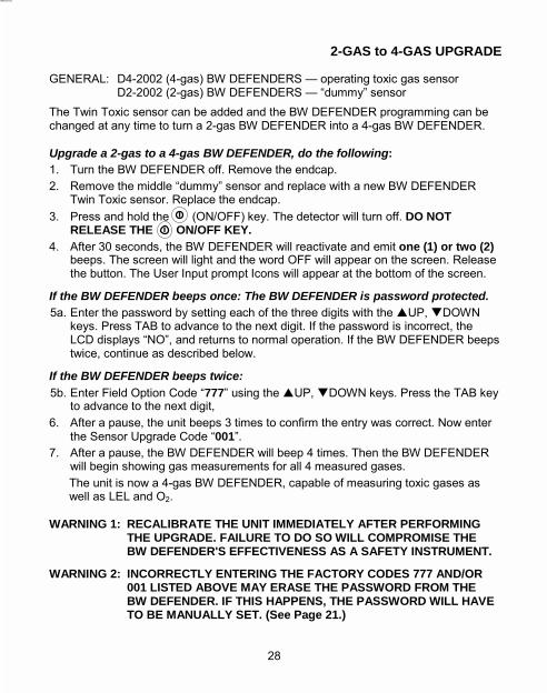
Page 10
GETTING STARTED DISPLAY ICONS GENERAL: BW DEFENDER icons and intelligent alpha-numeric display provide clear �Status at a Glance� advice at all times. Only applicable icons will be displayed at any one time. What the Various Icons Mean:
1) Alarm Icons: One or more of these icons will light up during an alarm condition: HIGH indicates high alarm; LOW indicates low alarm. Both HIGH and LOW are lit up during a Multiple Gas sensor alarm.
2) Gas Bar Icons: Identify the gas measured and the units of measure (ppm, %, and %LEL). Gases not being measured are not displayed.
3) Calibration Icons: Shown only when the unit is performing calibration operations.
4) Key Icon: Appears when calibration and alarm setpoint adjustment is password protected, or locked out. Also appears if the password is required from the user.
5) Up and Down Arrows: Appear when the unit is waiting for user input. This occurs during password entry and alarm setpoint entry.
6) Fan Icon: Indicates condition of the motorized sampling pump (if one is installed). The fan spins if pump is operational, and flashes when the pump is plugged.
7) Battery Icons: Continuously display the condition of the battery.
2-GAS to 4-GAS UPGRADE GENERAL: D4-2002 (4-gas) BW DEFENDERS � operating toxic gas sensor D2-2002 (2-gas) BW DEFENDERS � �dummy� sensor The Twin Toxic sensor can be added and the BW DEFENDER programming can be changed at any time to turn a 2-gas BW DEFENDER into a 4-gas BW DEFENDER. Upgrade a 2-gas to a 4-gas BW DEFENDER, do the following: 1. Turn the BW DEFENDER off. Remove the endcap. 2. Remove the middle �dummy� sensor and replace with a new BW DEFENDER
Twin Toxic sensor. Replace the endcap. 3. Press and hold the (ON/OFF) key. The detector will turn off. DO NOT
RELEASE THE ON/OFF KEY. 4. After 30 seconds, the BW DEFENDER will reactivate and emit one (1) or two (2)
beeps. The screen will light and the word OFF will appear on the screen. Release the button. The User Input prompt Icons will appear at the bottom of the screen.
If the BW DEFENDER beeps once: The BW DEFENDER is password protected. 5a. Enter the password by setting each of the three digits with the !UP, "DOWN
keys. Press TAB to advance to the next digit. If the password is incorrect, the LCD displays �NO�, and returns to normal operation. If the BW DEFENDER beeps twice, continue as described below.
If the BW DEFENDER beeps twice: 5b. Enter Field Option Code �777� using the !UP, "DOWN keys. Press the TAB key
to advance to the next digit, 6. After a pause, the unit beeps 3 times to confirm the entry was correct. Now enter
the Sensor Upgrade Code �001�. 7. After a pause, the BW DEFENDER will beep 4 times. Then the BW DEFENDER
will begin showing gas measurements for all 4 measured gases. The unit is now a 4-gas BW DEFENDER, capable of measuring toxic gases as well as LEL and O2.
WARNING 1: RECALIBRATE THE UNIT IMMEDIATELY AFTER PERFORMING THE UPGRADE. FAILURE TO DO SO WILL COMPROMISE THE BW DEFENDER'S EFFECTIVENESS AS A SAFETY INSTRUMENT.
WARNING 2: INCORRECTLY ENTERING THE FACTORY CODES 777 AND/OR 001 LISTED ABOVE MAY ERASE THE PASSWORD FROM THE BW DEFENDER. IF THIS HAPPENS, THE PASSWORD WILL HAVE TO BE MANUALLY SET. (See Page 21.)
7 28
Updated Nov, 2000 English D1218/3 Page 28 (models changed to D4-2002, D2-2002; last sentence changed to page 21)
7

Page 9
WRIST STRAP 1. Thread the split ring onto the silver
lanyard anchor located on the bottom back of the unit. Attach the strap to the split ring. The strap has a break away safety feature.
BW DEFENDER KEYPAD GENERAL: All operating features and functions are activated by the rubber keypad. The keypad operation is designed to prevent accidental activation of any function. The BW DEFENDER will advise you each time a function is accessed, and when automatic functions, are taking place. Press the keys down firmly. Each button has multiple functions, which are discussed in the appropriate sections of this manual.
TROUBLESHOOTING This section lists some common errors and their solutions. If you are unable to solve the problem, please contact BW Technologies for assistance.
Problem Possible Cause Solution Unit will not turn ON. No battery.
Battery is dead. Unit is damaged or defective.
Install battery. Replace and/or recharge battery. Contact BW.
Display doesn't show CO or H2S measurements.
This is a 2-gas version BW DEFENDER, which does not measure toxic gases.
Contact BW for kit to upgrade to the, 4-gas version (D4-2002).
Unit does not display TWA measurements.
This is a 2-gas version BW DEFENDER, which does not measure toxic gases.
Contact BW for kit to upgrade to the 4-gas version.
Unit does not enter alarm.
Alarm points are set incorrectly. Alarm setpoint(s) may be set to zero (off). Unit is in calibration mode.
Reset alarm setpoints to correct values. Reset alarm setpoints to correct values. Recalibrate unit immediately.
Unit enters alarm immediately when turned on.
Sensors are not yet stable. Battery warning alarm - battery is weak. Sampling pump is plugged. Sensor is missing from unit; or defective sensor.
Wait for 60 seconds. Replace/recharge battery. Remove obstruction. Replace sensor.
Unit does not respond to keypad.
Battery is dead. Unit is performing operations that require no user input.
Replace and/or recharge battery. Keypad operation will be automatically restored at the appropriate time.
Unit does not accurately measure gas.
Unit requires recalibration. Unit is colder/hotter than gas being measured. Sensor screens are clogged and dirty. Sensor(s) require(s) replacement. Sensor is missing from unit.
Recalibrate unit. Allow unit to acquire ambient temperature before use. Clean sensors. Replace sensor(s). Replace sensor.
Unit does not display maximum level of oxygen detected.
Peak detection for oxygen: displays the lowest value, not the highest value detected.
Unit is operating normally.
29 6
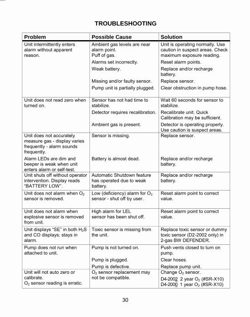
Page 8
GETTING STARTED BATTERY GENERAL: For safety and ease of use, the battery is housed in an exterior separate battery compartment. You never have to open the monitor to change, or charge, the batteries. OPERATION: 12-13 hours on rechargeable NiCad
(8-8.5 hours with motorized Pump) WARNING: ONLY USE THE BLACK & DECKER VERSAPAK™ VP100 BATTERY
INSERTING THE BATTERY 1. Unlock the tan battery lock ring by
sliding it fully left.
2. Insert the battery (contact end first) into the unit until it is fully inserted.
3. Rotate battery lock ring from UNLOCKED to the LOCKED (fully right) position to hold the battery in place. The lock ring will click into place when it is fully sealed.
CAUTION: THE BATTERY LOCK RING MUST BE FULLY ENGAGED (CLICKED SHUT IN THE “LOCK” POSITION) BEFORE USE.
REMOVING THE BATTERY 1. Slide the battery lock ring to
UNLOCKED position (fully left) and pull the battery straight out.
WARNING: DO NOT REMOVE OR REPLACE THE BATTERY IN A HAZARDOUS AREA. DOING SO WILL IMPAIR THE INTRINSIC SAFETY OF THE UNIT, AND MAY LEAD TO FIRE OR EXPLOSION.
TROUBLESHOOTING
Problem Possible Cause Solution Unit intermittently enters alarm without apparent reason.
Ambient gas levels are near alarm point. Puff of gas. Alarms set incorrectly. Weak battery. Missing and/or faulty sensor. Pump unit is partially plugged.
Unit is operating normally. Use caution in suspect areas. Check maximum exposure reading. Reset alarm points. Replace and/or recharge battery. Replace sensor. Clear obstruction in pump hose.
Unit does not read zero when turned on.
Sensor has not had time to stabilize. Detector requires recalibration. Ambient gas is present.
Wait 60 seconds for sensor to stabilize. Recalibrate unit. Quick Calibration may be sufficient. Detector is operating properly. Use caution is suspect areas.
Unit does not accurately measure gas - display varies frequently - alarm sounds frequently. Alarm LEDs are dim and beeper is weak when unit enters alarm or self-test.
Sensor is missing. Battery is almost dead.
Replace sensor. Replace and/or recharge battery.
Unit shuts off without operator intervention. Display reads �BATTERY LOW�.
Automatic Shutdown feature has operated due to weak battery.
Replace and/or recharge battery.
Unit does not alarm when O2 sensor is removed.
Low (deficiency) alarm for O2 sensor - shut off by user.
Reset alarm point to correct value.
Unit does not alarm when explosive sensor is removed from unit.
High alarm for LEL sensor has been shut off.
Reset alarm point to correct value.
Unit displays �SE� in both H2S and CO displays; stays in alarm.
Toxic sensor is missing from the unit.
Replace toxic sensor or dummy toxic sensor (D2-2002 only) in 2-gas BW DEFENDER.
Pump does not run when attached to unit.
Pump is not turned on. Pump is plugged. Pump is defective.
Push vents closed to turn on pump. Clear hoses. Replace pump unit.
Unit will not auto zero or calibrate. O2 sensor reading is erratic.
O2 sensor replacement may not be compatible.
Change O2 sensor. D4-2002 2 year O2 (#SR-X10) D4-2000 1 year O2 (#SR-X10)
5 30
Updated Nov, 2000 English D1218/3 Page 30 (changed to D2-2002; Added last row for oxygen
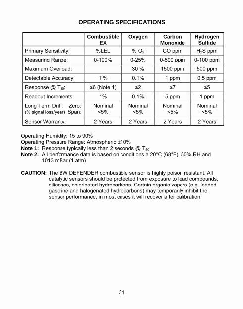
Page 7
GETTING STARTED POWER GENERAL: Familiarize yourself with all operating features and functions of the BW DEFENDER. The BW DEFENDER is calibrated at the factory. User selectable Alarm Setpoints have been set to relevant safety standards. The BW DEFENDER will advise the current Alarm Setpoints each time it is turned ON. If the user wishes to reset the Alarm Setpoints, refer to �ADJUSTING ALARM SETPOINTS�. BATTERY AND CHARGER: Batteries must be charged before use. WARNING: ONLY CHARGE BATTERIES USING A BLACK & DECKER
VERSAPAK™ CHARGER. DO NOT USE ANY OTHER CHARGER. FAILURE TO OBSERVE THIS PRECAUTION COULD LEAD TO FIRE OR EXPLOSION.
CAUTION: READ AND OBSERVE ALL INSTRUCTIONS AND PRECAUTIONS IN
THE BLACK & DECKER LITERATURE PROVIDED WITH THE BW DEFENDER. FAILURE TO DO SO MAY RESULT IN FIRE, ELECTRIC SHOCK OR OTHER FORMS OF PERSONAL INJURY OR PROPERTY DAMAGE.
FIRST TIME CHARGE: The charger supplied with the BW DEFENDER is a VAC
2-port charger, which requires approximately 6 hours (both batteries) for a first time charge.
NORMAL CHARGE TIME: After the first use, battery charging times decrease.
Normal charge time: 2-port VAC Charger - 3-4 hours for 1 to 2 batteries
Black & Decker VERSAPAK� chargers (other than the 2-port charger included with the BW DEFENDER) may be used with BW DEFENDER batteries. Refer to the instruction manual provided with the specific charger unit for charging instructions. NOTE: Batteries can be left in the VAC charger until required for use.
OPERATING SPECIFICATIONS
Operating Humidity: 15 to 90% Operating Pressure Range: Atmospheric ±10% Note 1: Response typically less than 2 seconds @ T50 Note 2: All performance data is based on conditions a 20°C (68°F), 50% RH and
1013 mBar (1 atm) CAUTION: The BW DEFENDER combustible sensor is highly poison resistant. All
catalytic sensors should be protected from exposure to lead compounds, silicones, chlorinated hydrocarbons. Certain organic vapors (e.g. leaded gasoline and halogenated hydrocarbons) may temporarily inhibit the sensor performance, in most cases it will recover after calibration.
Combustible EX
Oxygen Carbon Monoxide
Hydrogen Sulfide
Primary Sensitivity: %LEL % O2 CO ppm H2S ppm Measuring Range: 0-100% 0-25% 0-500 ppm 0-100 ppm
Maximum Overload: 30 % 1500 ppm 500 ppm
Detectable Accuracy: 1 % 0.1% 1 ppm 0.5 ppm
Response @ T50: ≤6 (Note 1) ≤2 ≤7 ≤5
Readout Increments: 1% 0.1% 5 ppm 1 ppm
Long Term Drift: Zero: (% signal loss/year) Span:
Nominal <5%
Nominal <5%
Nominal <5%
Nominal <5%
Sensor Warranty: 2 Years 2 Years 2 Years 2 Years
31 4
Updated English D1218/3 Nov/00 P31. (O2 warranty changes to 2 years) Nov/00 P4. (deleted D4-VP160 in three places)
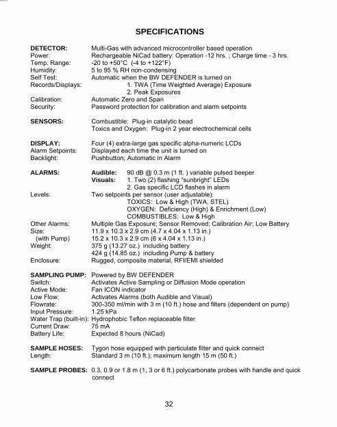
Page 6
SPECIFICATIONS DETECTOR: Multi-Gas with advanced microcontroller based operation Power: Rechargeable NiCad battery: Operation -12 hrs. ; Charge time - 3 hrs. Temp. Range: -20 to +50°C (-4 to +122°F) Humidity: 5 to 95 % RH non-condensing Self Test: Automatic when the BW DEFENDER is turned on Records/Displays: 1. TWA (Time Weighted Average) Exposure 2. Peak Exposures Calibration: Automatic Zero and Span Security: Password protection for calibration and alarm setpoints SENSORS: Combustible: Plug-in catalytic bead Toxics and Oxygen: Plug-in 2 year electrochemical cells DISPLAY: Four (4) extra-large gas specific alpha-numeric LCDs Alarm Setpoints: Displayed each time the unit is turned on Backlight: Pushbutton; Automatic in Alarm ALARMS: Audible: 90 dB @ 0.3 m (1 ft. ) variable pulsed beeper Visuals: 1. Two (2) flashing �sunbright� LEDs
2. Gas specific LCD flashes in alarm Levels: Two setpoints per sensor (user adjustable):
TOXICS: Low & High (TWA, STEL) OXYGEN: Deficiency (High) & Enrichment (Low) COMBUSTIBLES: Low & High
Other Alarms: Multiple Gas Exposure; Sensor Removed; Calibration Air; Low Battery Size: 11.9 x 10.3 x 2.9 cm (4.7 x 4.04 x 1.13 in.) (with Pump) 15.2 x 10.3 x 2.9 cm (6 x 4.04 x 1.13 in.) Weight: 375 g (13.27 oz.) including battery 424 g (14.85 oz.) including Pump & battery Enclosure: Rugged, composite material, RFI/EMI shielded SAMPLING PUMP: Powered by BW DEFENDER Switch: Activates Active Sampling or Diffusion Mode operation Active Mode: Fan ICON indicator Low Flow: Activates Alarms (both Audible and Visual) Flowrate: 300-350 ml/min with 3 m (10 ft.) hose and filters (dependent on pump) Input Pressure: 1.25 kPa Water Trap (built-in): Hydrophobic Teflon replaceable filter Current Draw: 75 mA Battery Life: Expected 8 hours (NiCad) SAMPLE HOSES: Tygon hose equipped with particulate filter and quick connect Length: Standard 3 m (10 ft.); maximum length 15 m (50 ft.) SAMPLE PROBES: 0.3, 0.9 or 1.8 m (1, 3 or 6 ft.) polycarbonate probes with handle and quick
connect
Fig.1: BW DEFENDER FEATURE DRAWING
A Low & High Alarm Setpoints Display each time the unit is turned ON
B Black & Decker �VersaPak� rechargeable battery with locking switch
C Dual Mode Sampling Pump
D �Sunbright� Flashing Alarm LEDs
E Audible Alarm
F One Button Operation
G Keypad to set Alarm Levels and Enter Password
H Stores TWA and Peak functions
This manual covers the following BW DEFENDER instruments: Note: The models listed below contain the new BW Defender 2 year oxygen sensor. Order No. Description D4-2002 4-gas Detector D4-2002-SP 4-gas Detector (motorized Sampling Pump installed) D2-2002 2-gas Detector Note: To include 110 VAC charger add no suffix. To exclude charger add suffix: “-A”. To include 230 VAC charger add suffix: “-UK” - UK/Ireland plug; “-EU” Continental European plug. Table 1: BW DEFENDER GAS DETECTORS
Gas Monitored Gas Bar Symbol Unit of Measure BW Defender
Version Oxygen O2 % of ambient air 4-gas
2-gas Explosive Gases EX % of lower explosive limit (LEL) Carbon Monoxide CO Parts-per-million (ppm) Hydrogen Sulfide H2S Parts-per-million (ppm)
4-gas only
3 32
Updated Nov, 2000 English D1218/3 Page 3 (models changed to D4-2002, D2-2002, to D4-2002-SP)
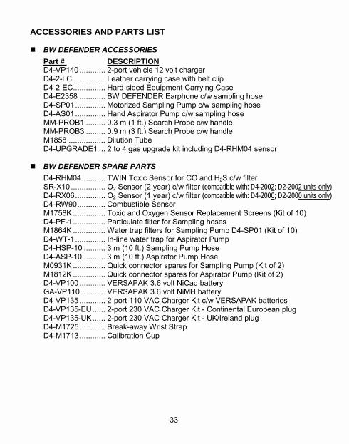
Page 5
BW DEFENDER FEATURES ! AUTOMATIC ZERO: Sets oxygen range to 20.9% and other ranges to zero and
automatically nullifies small differences in sensor output in a limited range. ! USER SETTABLE ALARM LEVELS: Simply reset the factory set levels with the
UP/DOWN keys to change alarm levels. ! PEAK EXPOSURES ENCOUNTERED: Displays the highest combustible and
toxic gas levels, plus the lowest oxygen level since the instrument was last cleared or turned ON.
! TWA MODE: Display of accumulated Time-Weighted-Average level for toxic gas
range(s) since the last time the memory was turned ON. ! LOW BATTERY WARNING: Both audible and visual warnings advise there is
approximately 30 minutes of operation left. The audible will chirp every 7 seconds, ALARM and LOW BATTERY icons will light, and the alarm LEDs will flash.
! GAS ALARM PRIORITY: Gas alarms take priority over any other type of alarm. ! RUGGED RFI RESISTANT DESIGN: BW DEFENDER is constructed of
composite RFI materials for advance RFI protection. The rugged enclosure has been designed with added strength to endure industrial use.
! CONVENIENCE AND SAFETY: Monitor in either active or diffusion mode at the
flip of a switch when using a BW DEFENDER equipped with Sampling Pump. The low maintenance, high efficiency rotary vane pump design provides better reliability.
ACCESSORIES AND PARTS LIST ! BW DEFENDER ACCESSORIES
Part # DESCRIPTION D4-VP140 ............ 2-port vehicle 12 volt charger D4-2-LC ............... Leather carrying case with belt clip D4-2-EC ............... Hard-sided Equipment Carrying Case D4-E2358 ............ BW DEFENDER Earphone c/w sampling hose D4-SP01 .............. Motorized Sampling Pump c/w sampling hose D4-AS01 .............. Hand Aspirator Pump c/w sampling hose MM-PROB1 ......... 0.3 m (1 ft.) Search Probe c/w handle MM-PROB3 ......... 0.9 m (3 ft.) Search Probe c/w handle M1858 ................. Dilution Tube D4-UPGRADE1 ... 2 to 4 gas upgrade kit including D4-RHM04 sensor
! BW DEFENDER SPARE PARTS
D4-RHM04 ........... TWIN Toxic Sensor for CO and H2S c/w filter SR-X10 ................ O2 Sensor (2 year) c/w filter (compatible with: D4-2002; D2-2002 units only) D4-RX06 .............. O2 Sensor (1 year) c/w filter (compatible with: D4-2000; D2-2000 units only) D4-RW90 ............. Combustible Sensor M1758K ............... Toxic and Oxygen Sensor Replacement Screens (Kit of 10) D4-PF-1 ............... Particulate filter for Sampling hoses M1864K ............... Water trap filters for Sampling Pump D4-SP01 (Kit of 10) D4-WT-1 .............. In-line water trap for Aspirator Pump D4-HSP-10 .......... 3 m (10 ft.) Sampling Pump Hose D4-ASP-10 .......... 3 m (10 ft.) Aspirator Pump Hose M0931K ............... Quick connector spares for Sampling Pump (Kit of 2) M1812K ............... Quick connector spares for Aspirator Pump (Kit of 2) D4-VP100 ............ VERSAPAK 3.6 volt NiCad battery GA-VP110 ........... VERSAPAK 3.6 volt NiMH battery D4-VP135 ............ 2-port 110 VAC Charger Kit c/w VERSAPAK batteries D4-VP135-EU ...... 2-port 230 VAC Charger Kit - Continental European plug D4-VP135-UK ...... 2-port 230 VAC Charger Kit - UK/Ireland plug D4-M1725 ............ Break-away Wrist Strap D4-M1713 ............ Calibration Cup
33 2
Updated English D1218/3 P.2 Nov/00 (removed 2nd last bullet on Approvals) Nov/00 P.33 (2 year O2 sensor added and 1 year O2 sensor distinguished from 2 year; D4-VP160 removed; D4-1-LC changed to D4-2-LC –fits Schwartzer pump)
Page 4
BW DEFENDER INTRODUCTION The BW DEFENDER is designed for field friendly operation with large, bright, gas/alarm indicators and one button operation. The BW DEFENDER provides effective protection with the advantage of microcontroller based operation and the most advanced sensing technology available. ! ADVANCED SENSING TECHNOLOGY: The NEW TWIN TOXIC sensor
employed in the BW DEFENDER has two separate chambers within one sensor enclosure which provide independent gas sensing and signal outputs. This is not to be confused with Dual Toxic sensors which are simply unfiltered carbon monoxide sensors.
! BLACK & DECKER VERSAPAK™ VP100 BATTERY OPERATION: The NiCad
batteries are readily available in over 70 countries worldwide. VP100 batteries are designed with zero memory cells for repetitive charging. Standard recharge time with a VAC Charger is three hours. The batteries can be left in the VAC charger (provided) without damage. VERSAPAK batteries have a minimum life of 300 charge cycles.
! MICROCONTROLLER BASED OPERATION: The BW DEFENDER is designed
with a microcontroller that ensures reliability. The advanced minicomputer in the BW DEFENDER offers more built-in features and functions.
! LIQUID CRYSTAL DISPLAY: The extra-large LCD indicates the gas and
concentrations for 4 gases at one time. As well, it advises whenever the BW DEFENDER is performing automatic functions. The graphic display icons provide simple and clear alarm status advice.
! DISPLAY BACKLIGHTING: The backlight automatically activates whenever an
alarm condition exists. This feature can be accessed at any time with the touch of a button to view the display in poor light.
BW DEFENDER MULTI-GAS DETECTOR comes complete with:
• Wrist Strap • Black & Decker Two-Port 110 VAC Charger c/w Manual • 2 VERSAPAK NiCad Batteries • Calibration Cup • BW DEFENDER Manual
Also available BW Defender Confined Space Kits D4-CS-KIT BW Defender Confined Space Kit with Motorized Sampling Pump D4-AS-KIT BW Defender Confined Space Kit with Aspirator Sampling Pump Note 1: Order Number D4-2002-SP (Motorized Sampling Pump - included;
Calibration Cup - not included since not required). Note 2: Order with the suffix �-A� to exclude the 2-port charger. Note 3: Order with the suffix �-EU� for 230 VAC Charger - Continental European plug Note 4: Order with the suffix �-UK� for 230 VAC Charger - UK/Ireland plug
CALIBRATION RECORDS Date Calibrated Calibrated By
1 34
Updated May 30, 2000 English D1218-2.1 Page 1 (City Removed, -EU model added) P34. English D1218/3: Nov/00 (model D4-2000-SP changed to D4-2002-SP) Feb 12/01 (Note 3/4 “-EU,-UK”, Note 2,3 “models” to “order”)
Page 3
BW DEFENDER Operator's Manual TABLE OF CONTENTS
Features .............................................................................................................. 1 Order Numbers and Gases ................................................................................ 3 Getting Started
Power ............................................................................................................... 4 Battery (Insertion and Removal) ............................................................................. 5 Wrist Strap ......................................................................................................... 6 BW DEFENDER Keypad ...................................................................................... 6 Display Icons ...................................................................................................... 7
Operation Activating the Detector ......................................................................................... 8 Deactivating the Detector ...................................................................................... 9 Backlight Display ................................................................................................. 9 Battery Test ........................................................................................................ 10 Auto-Shutdown ................................................................................................... 10 Accumulated Exposure Levels (TWA and PEAK Exposure) ........................................ 11 Description of Alarm Setpoints ............................................................................... 12 Audible & Visual Gas Alarm Patterns ..................................................................... 13 Low Battery Alarm ............................................................................................... 14 Missing Sensor Alarm .......................................................................................... 14
Confined Space Entry ........................................................................................ 15 Motorized Sampling Pump: Features and Installation ................................................. 16 Operation and Low Flow Alarm ......................................... 17 Built-in Water Trap ......................................................... 18 Manual Aspirator Pump ........................................................................................ 19
Daily Operation ................................................................................................... 20 Maintenance
Auto Zero for all Sensors ...................................................................................... 21 Password Protection ............................................................................................ 21 BW DEFENDER Care .......................................................................................... 22 Calibration ......................................................................................................... 23 Adjusting The Alarm Setpoints ............................................................................... 24 Sensor Replacement ........................................................................................... 26
Field Options Confidence Beep Enable ...................................................................................... 27 2 Gas to 4 Gas BW DEFENDER Upgrade ............................................................... 28
Troubleshooting Guide ...................................................................................... 29 Operating Specifications .................................................................................. 31 Accessories and Parts List: BW DEFENDER Packing List ............................... 33 Calibration Record Chart ................................................................................... 34 Manufacturer’s Special Warnings ..................................................................... 35
Manufactured by: BW TECHNOLOGIES
SPECIAL WARNINGS
Through engineering, design and testing as well as rigid manufacturing techniques and quality control, BW Technologies supplies the finest gas detection instrumentation available. The BW DEFENDER is designed to provide optimum performance and lower maintenance in rugged industrial use. The user, though, must recognize responsibility for maintaining the instrument in operational condition, ensuring proper operation and long-term use. 1. Calibrate the detector before first-time use, and then at least once every 90 days. 2. It is recommended that the accuracy of the BW Defender be checked with known
concentration calibration gas before each day�s use and immediately after any know exposure to contaminants.
3. The LEL sensor is factory calibrated to methane. If monitoring a different combustible gas, calibrate the sensor using the appropriate gas.
4. BW recommends that a calibration check on a regular schedule, one at least every 30 days.
5. Do not expose BW DEFENDER to electrical shock and/or severe continuous mechanical shock.
6. Do not attach any other piece of equipment to the BW DEFENDER except those supplied by BW for the BW DEFENDER.
7. Do not operate or attempt to modify the BW DEFENDER to operate on any battery or power source except the battery approved by BW Technologies.
8. Do not attempt to disassemble, adjust or service the instrument unless instructions are contained in the manual for that procedure and/or that part is listed as a replaceable part. Use only BW DEFENDER replaceable parts.
9. Do not immerse in liquid OR use high power sprays on the instrument. 10. Do not allow the sensor screens to become dirty or clogged. 11. BW Technologies gas detection instruments are primarily SAFETY devices for
the protection of personnel and facilities and must always be �ready�. With proper maintenance the BW DEFENDER will provide many years of service. The user must assume all liability for misuse of BW Technologies gas detection instruments.
12. The instruments warranty will be voided if customer personnel or third parties damage the instrumentation during repair attempts.
Because BW Technologies is constantly developing and improving its products line, we reserve the right to change specifications without notice.
35

Page 2
IMPORTANT
PLEASE READ THIS ENTIRE MANUAL AND FOLLOW THE INSTRUCTIONS AND RECOMMENDATIONS CONTAINED HEREIN IN ORDER TO ENSURE PROPER AND SAFE OPERATION AND FUNCTIONING OF THE BW DEFENDER MULTI-GAS DETECTOR.
USE OF THE BW DEFENDER REQUIRES A FULL UNDERSTANDING OF THE OPERATING AND MAINTENANCE INSTRUCTIONS. IT IS ONLY TO BE USED FOR THE PURPOSES SPECIFIED IN THE MANUAL.
INTENDED USE: THE BW DEFENDER IS A MULTI-GAS PERSONAL DETECTOR INTENDED FOR AMBIENT AIR MONITORING.
WARNING: Substitution of components may impair Intrinsic Safety. AVERTISSEMENT: La substitution de composants peut compromettre la securite
intrinseque. CAUTION: Do not change or charge batteries in a hazardous location. CAUTION: The LEL range of this monitor is factory calibrated to methane. If
monitoring a different combustible gas, calibrate the combustible range of the monitor to the appropriate
CAUTION: FOR SAFETY REASONS THIS EQUIPMENT MUST BE OPERATED AND SERVICED BY QUALIFIED PERSONNEL ONLY. READ AND UNDERSTAND INSTRUCTION MANUAL COMPLETELY BEFORE OPERATING AND SERVICING.
CAUTION: Extended exposure of the BW Defender to certain concentrations of combustible gases and air may stress a detector element, which can seriously affect its performance. If an alarm occurs due to high concentration of combustible gases, recalibration should be performed, or if needed the sensor replaced.
Prior to each day's usage sensitivity must be tested on a known concentration of the target combustible gas (methane, etc.) equivalent to 25-50% of full scale concentration (accuracy must be with 0 to +20% of actual). Accuracy may be corrected by recalibrating the instrument.
The BW DEFENDER and motorized sampling pump is Approved by: CSA to U.S. and Canadian Standards - Class I, Div. 1, Groups A, B, C, D; Class I, Zone 0, Gr. IIC. Cenelec Certified by LCIE � EEx ia d IIC. CE declared for European conformity. ABS (American Standards Type Approval) to become part of a Classified Vessel. Certified for use in Australia - Ex ia s IIC for Zone 0 hazardous areas.
Limited Warranty & Limitation of Liability
BW Technologies warrants this product to be free from defects in material and workmanship under normal use and service for a period of two years, beginning on the date of shipment. Parts, product repairs and services are warranted for 90 days. This warranty extends only to the original buyer or end-user customer of a BW Technologies authorized reseller, and does not apply to fuses, disposable batteries or to any product which, in BW Technologies� opinion, has been misused, altered, neglected or damaged by accident or abnormal conditions of operation or handling. BW Technologies warrants that software will operate substantially in accordance with its functional specifications for 90 days and that it has been properly recorded on non-defective media. BW Technologies does not warrant that software will be error free or operate without interruption.
BW Technologies authorized resellers shall extend this warranty on new and unused products to end-user customers only but have no authority to extend a greater or different warranty on behalf of BW Technologies. Warranty support is available if product is purchased through a BW Technologies authorized sales outlet or Buyer has paid the applicable international price. BW Technologies reserves the right to invoice Buyer for importation costs of repair/replacement parts when product purchased in one country is submitted for repair in another country.
BW Technologies� warranty obligation is limited, at BW Technologies� option, to refund of the purchase price, free of charge repair, or replacement of a defective product which is returned to a BW Technologies authorized service center within the warranty period.
To obtain warranty service, contact your nearest BW Technologies authorized service center or send the product, with a description of the difficulty, postage and insurance prepaid (FOB Destination), to the nearest BW Technologies authorized service center. BW Technologies assumes no risk for damage in transit. Following warranty repair, the product will be returned to Buyer, transportation prepaid (FOB Destination). If BW Technologies determines that the failure was caused by misuse, alteration, accident or abnormal condition of operation or handling, BW Technologies will provide an estimate of repair costs and obtain authorization before commencing the work. Following repair, the product will be returned to the Buyer transportation prepaid and the Buyer will be billed for the repair and return transportation charges (FOB Shipping Point).
THIS WARRANTY IS BUYER'S SOLE AND EXCLUSIVE REMEDY AND IS IN LIEU OF ALL OTHER WARRANTIES, EXPRESS OR IMPLIED, INCLUDING BUT NOT LIMITED TO ANY IMPLIED WARRANTY OF MERCHANTABILITY OR FITNESS FOR A PARTICULAR PURPOSE. BW TECHNOLOGIES SHALL NOT BE LIABLE FOR ANY SPECIAL, INDIRECT, INCIDENTAL OR CONSEQUENTIAL DAMAGES OR LOSSES, INCLUDING LOSS OF DATA, WHETHER ARISING FROM BREACH OF WARRANTY OR BASED ON CONTRACT, TORT, RELIANCE OR ANY OTHER THEORY.
Since some countries or states do not allow limitation of the term of an implied warranty, or exclusion or limitation of incidental or consequential damages, the limitations and exclusions of this warranty may not apply to every buyer. If any provision of this Warranty is held invalid or unenforceable by a court of competent jurisdiction, such holding will not affect the validity or enforceability of any other provision.
BW Technologies Ltd. BW Technologies (America) BW Technologies (Europe) 242, 3030 � 3rd Ave. NE 2307 Oak Lane, Suite 2A100 101 Heyford Park, Calgary, AB T2A 6T7 Grande Prairie, TX 75051 Upper Heyford, Oxfordshire OX25 5HA Canada USA United Kingdom
D1218/3 Nov/00 - Warranty (GAMax, addresses) - Feb 25, 2001 (warranty: unhyphenate, omit UK/EU address “ltd.”, UK postal code)
SAA

Page 1
BW DEFENDER MULTI-GAS DETECTOR
Operator’s Manual
Order Numbers: D4-2002 D2-2002
Front Cover Back Cover
BW Technologies BW Technologies (America) BW Technologies (Europe) 2840 - 2 Ave. SE 3279 West Pioneer Parway 101 Heyford Park Calgary, AB T2A 7X9 Pantego, TX. 76013 Upper Heyford, Oxfordshire OX25 5HA Canada USA United Kingdom
English D1218/3
English D1218/3 - Nov 12/00 Cover Pages (New model #s on front cover; website, and Rev.3 on back cover) -and Feb 25, 2001 (std. Logos, UK postal code)
FOR SALES AND SERVICE CALL 1-800-663-4164 North America +44 (0) 1869-233004 Europe +1-403-248-9226 Other Countries Fax: +1-403-273-3708 all countries Email: [email protected] Web Site: www.gasmonitors.com


