163
HA University BW Technologies by Honeywell Instrument Repair

HA University
BW Technologies by Honeywell
Instrument Repair
2
Rev 1
General Repair Guidelines
• Prior to returning a monitor to customer always
– Calibrate
– Bump and check for stability
• By rules of intrinsic safety
– NO SOLDERING permitted
• Sensor Warranties
– NH3, ETO, ClO2, Cl2,O3, sensors carry 1 year warranty
– 3 year Clip Extremes have a 3 year warranty
– All others are 2 year
• Corroded monitors are not covered by warranty
– Not to be repaired
– Owner must buy new replacement
3
Rev 1
Universal Repair Tips
• If monitor display is missing segments
– Clean zebra strips
• Replace sensor if
– Sensor shows fail
– Fails to bump and calibrate
– Values constantly float up and down
• If unit has erratic toxic sensor
– Try airing out over a weekend and then recalibrating
– Often fixes poisoned sensors
• When reassembling a monitor
– Always turn counter clockwise until a click is felt then tighten
– If monitor has more than three stripped screws replace case
• 180 days is default calibration interval for GasAlert Family
4
Rev 1
Factors Affecting Battery Life
• Amount of time unit is in alarm
• How often backlight is used
• Operating Temperature
– Colder temperatures significantly shorten battery life
• Age of rechargeable battery
• Initial charge/discharge cycle
– Rechargeable batteries should be fully discharged then fully charged again 3
times to ensure maximum life
5
Rev 1
Monitor Cleaning
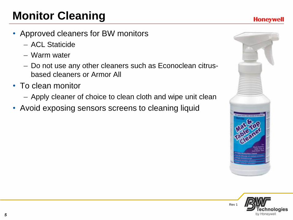
• Approved cleaners for BW monitors
– ACL Staticide
– Warm water
– Do not use any other cleaners such as Econoclean citrus-
based cleaners or Armor All
• To clean monitor
– Apply cleaner of choice to clean cloth and wipe unit clean
• Avoid exposing sensors screens to cleaning liquid
6
Rev 1
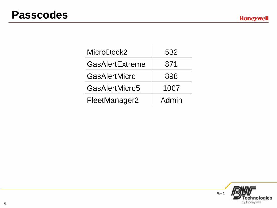
Passcodes
MicroDock2 532
GasAlertExtreme 871
GasAlertMicro 898
GasAlertMicro5 1007
FleetManager2 Admin
7
Rev 1
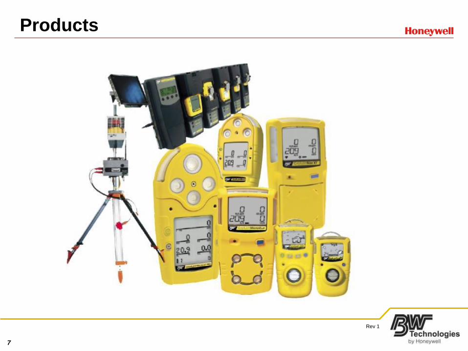
Products
8
Rev 1
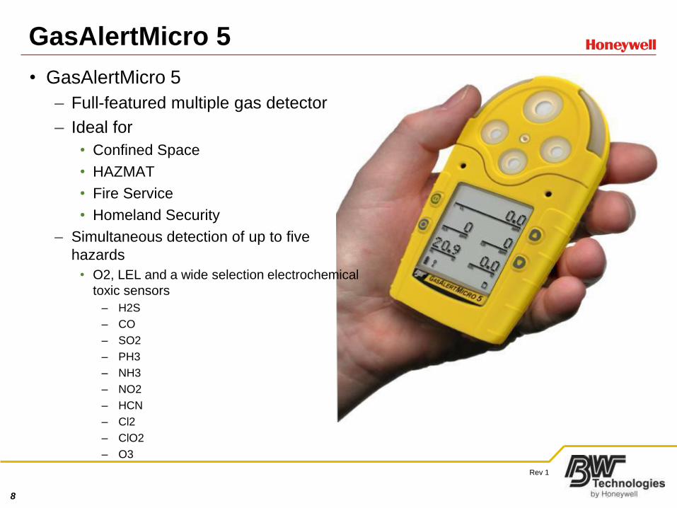
GasAlertMicro 5
• GasAlertMicro 5
– Full-featured multiple gas detector
– Ideal for
• Confined Space
• HAZMAT
• Fire Service
• Homeland Security
– Simultaneous detection of up to five
hazards
• O2, LEL and a wide selection electrochemical
toxic sensors
– H2S
– CO
– SO2
– PH3
– NH3
– NO2
– HCN
– Cl2
– ClO2
– O3
9
Rev 1
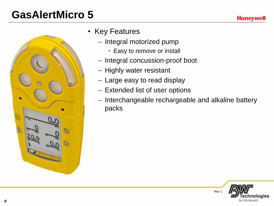
GasAlertMicro 5
• Key Features
– Integral motorized pump
• Easy to remove or install
– Integral concussion-proof boot
– Highly water resistant
– Large easy to read display
– Extended list of user options
– Interchangeable rechargeable and alkaline battery
packs
10
Rev 1
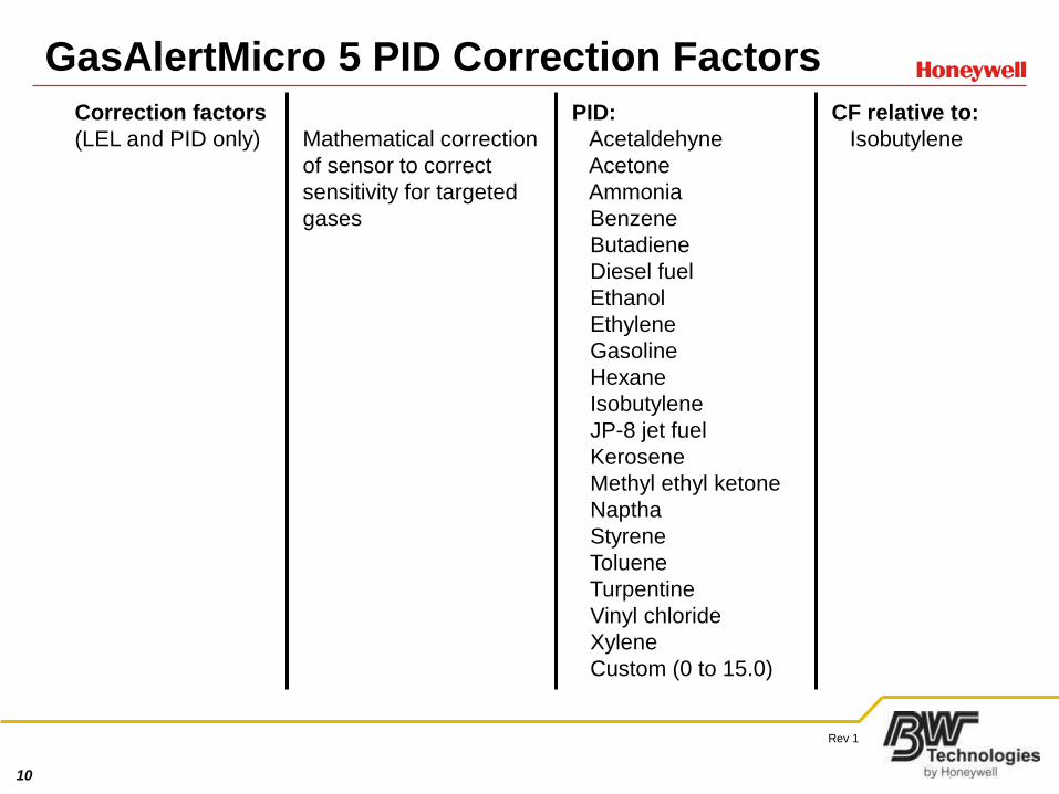
GasAlertMicro 5 PID Correction Factors
Correction factors
(LEL and PID only) Mathematical correction
of sensor to correct
sensitivity for targeted
gases
PID:
Acetaldehyne
Acetone
Ammonia
Benzene
Butadiene
Diesel fuel
Ethanol
Ethylene
Gasoline
Hexane
Isobutylene
JP-8 jet fuel
Kerosene
Methyl ethyl ketone
Naptha
Styrene
Toluene
Turpentine
Vinyl chloride
Xylene
Custom (0 to 15.0)
CF relative to:
Isobutylene
11
Rev 1
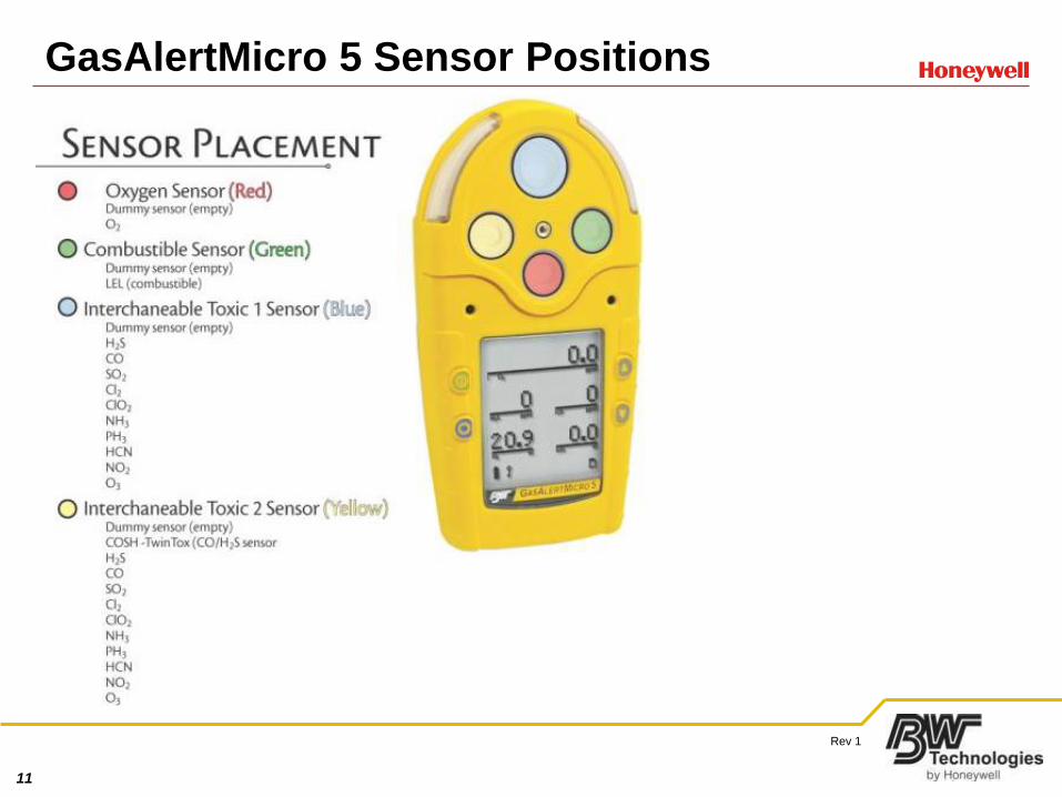
GasAlertMicro 5 Sensor Positions
12
Rev 1
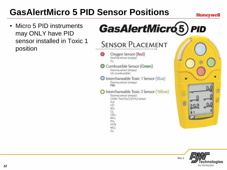
GasAlertMicro 5 PID Sensor Positions
• Micro 5 PID instruments
may ONLY have PID
sensor installed in Toxic 1
position

13
Rev 1
GasAlertMicro 5 IR Sensor Placement
14
Rev 1
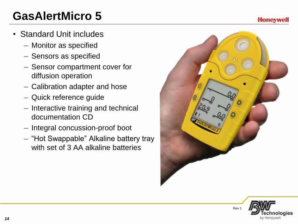
GasAlertMicro 5
• Standard Unit includes
– Monitor as specified
– Sensors as specified
– Sensor compartment cover for
diffusion operation
– Calibration adapter and hose
– Quick reference guide
– Interactive training and technical
documentation CD
– Integral concussion-proof boot
– “Hot Swappable” Alkaline battery tray
with set of 3 AA alkaline batteries
15
Rev 1
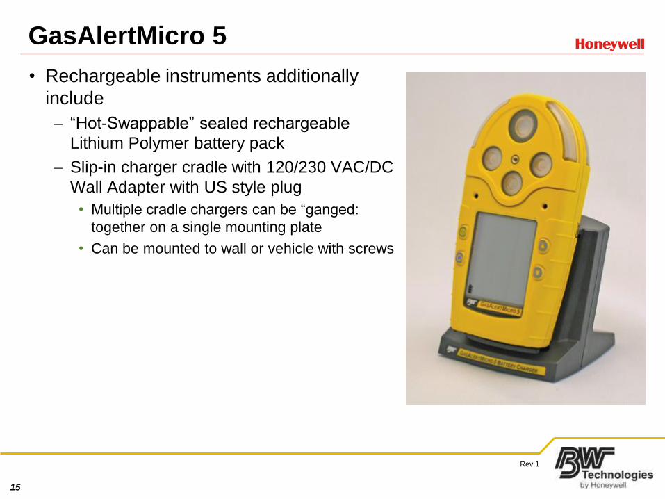
GasAlertMicro 5
• Rechargeable instruments additionally
include
– “Hot-Swappable” sealed rechargeable
Lithium Polymer battery pack
– Slip-in charger cradle with 120/230 VAC/DC
Wall Adapter with US style plug
• Multiple cradle chargers can be “ganged:
together on a single mounting plate
• Can be mounted to wall or vehicle with screws
16
Rev 1
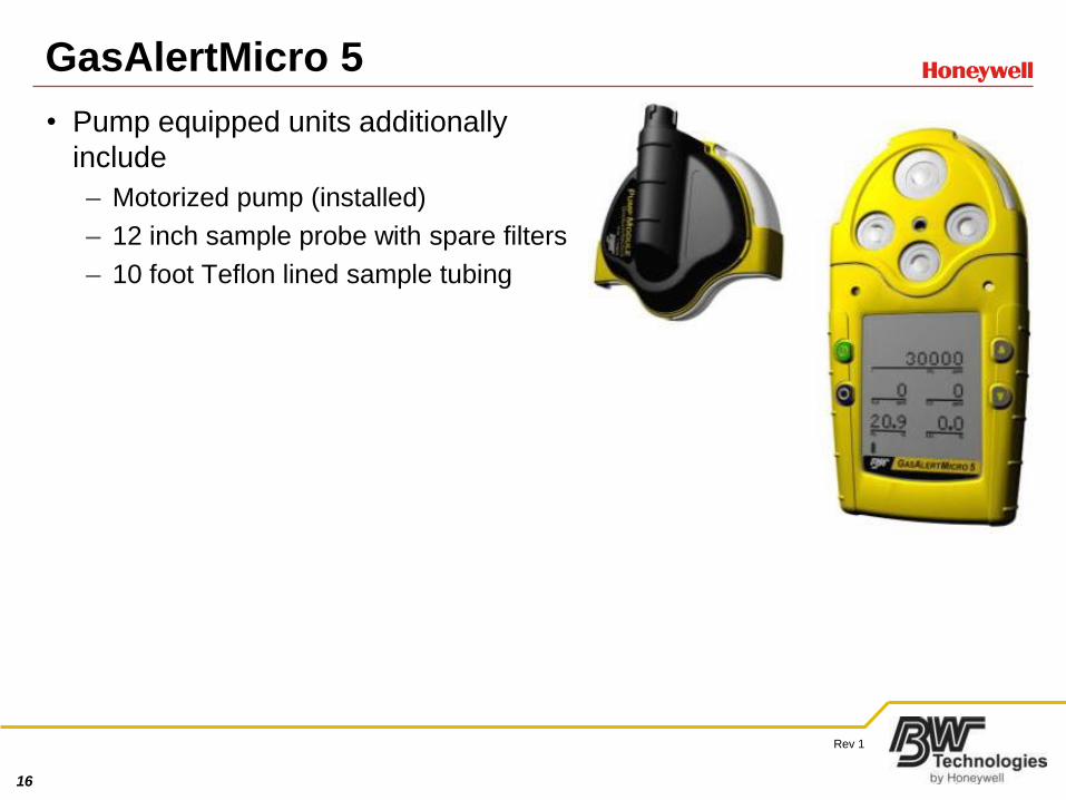
GasAlertMicro 5
• Pump equipped units additionally
include
– Motorized pump (installed)
– 12 inch sample probe with spare filters
– 10 foot Teflon lined sample tubing
17
Rev 1
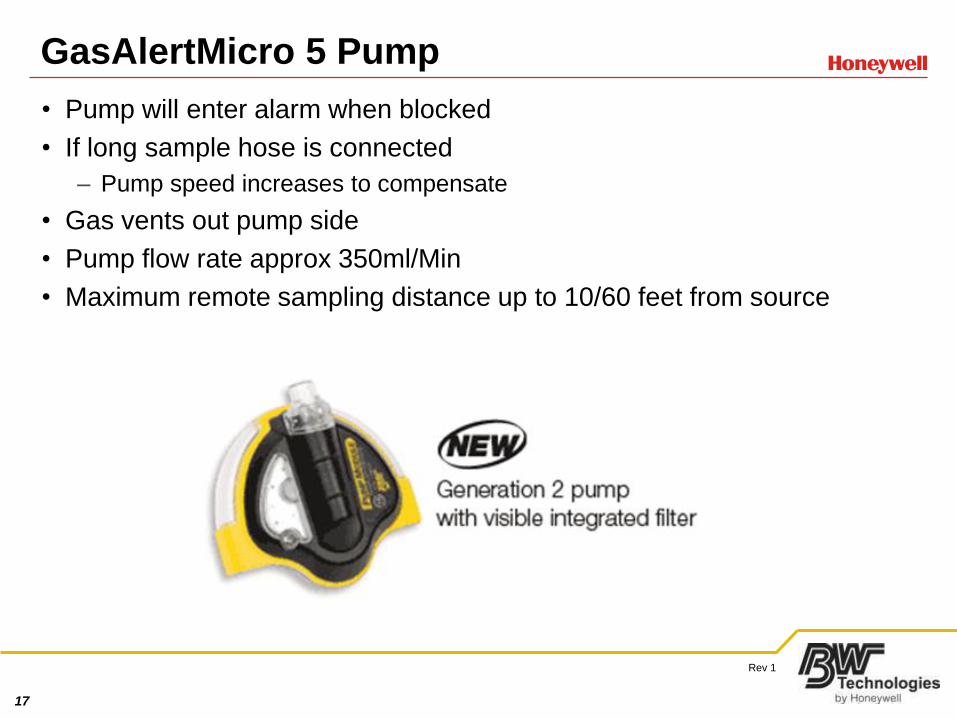
GasAlertMicro 5 Pump
• Pump will enter alarm when blocked
• If long sample hose is connected
– Pump speed increases to compensate
• Gas vents out pump side
• Pump flow rate approx 350ml/Min
• Maximum remote sampling distance up to 10/60 feet from source
18
Rev 1
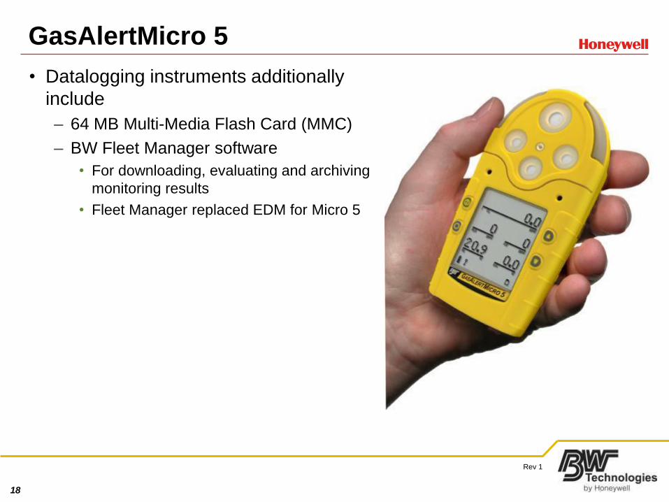
GasAlertMicro 5
• Datalogging instruments additionally
include
– 64 MB Multi-Media Flash Card (MMC)
– BW Fleet Manager software
• For downloading, evaluating and archiving
monitoring results
• Fleet Manager replaced EDM for Micro 5
19
Rev 1
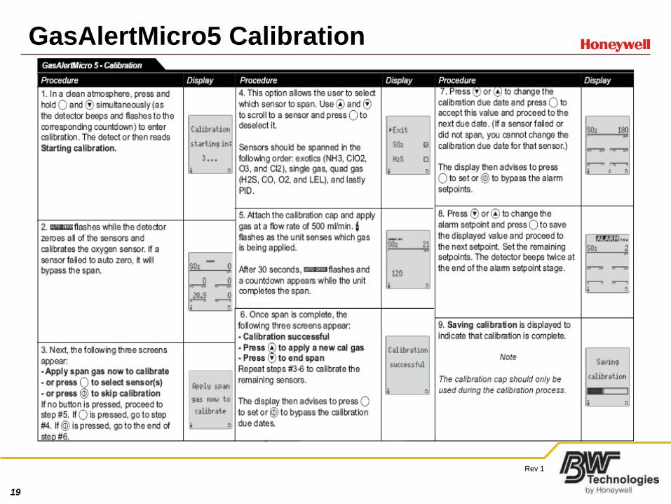
GasAlertMicro5 Calibration
20
Rev 1
GasAlertMicro5 Calibration Notes
• If calibrating with Chlorine
– Use a 1LPM regulator with no more than 5cm of hose
– Always calibrate chlorine after H2S
• When prompted to zero CO2 sensor
– Use nitrogen not fresh air
• Do not use LEL correction factors unless monitor is calibrated to
methane
• Check user options to ensure spans match calibration gas
• If toxic 2 sensor or 9 o’clock sensor is ammonia, chlorine, chlorine
dioxide or ozone use single gas calibration cap
• NH3 and SO2 cannot be present in same instrument
– Call for assistance if you encounter a unit in this configuration
21
Rev 1
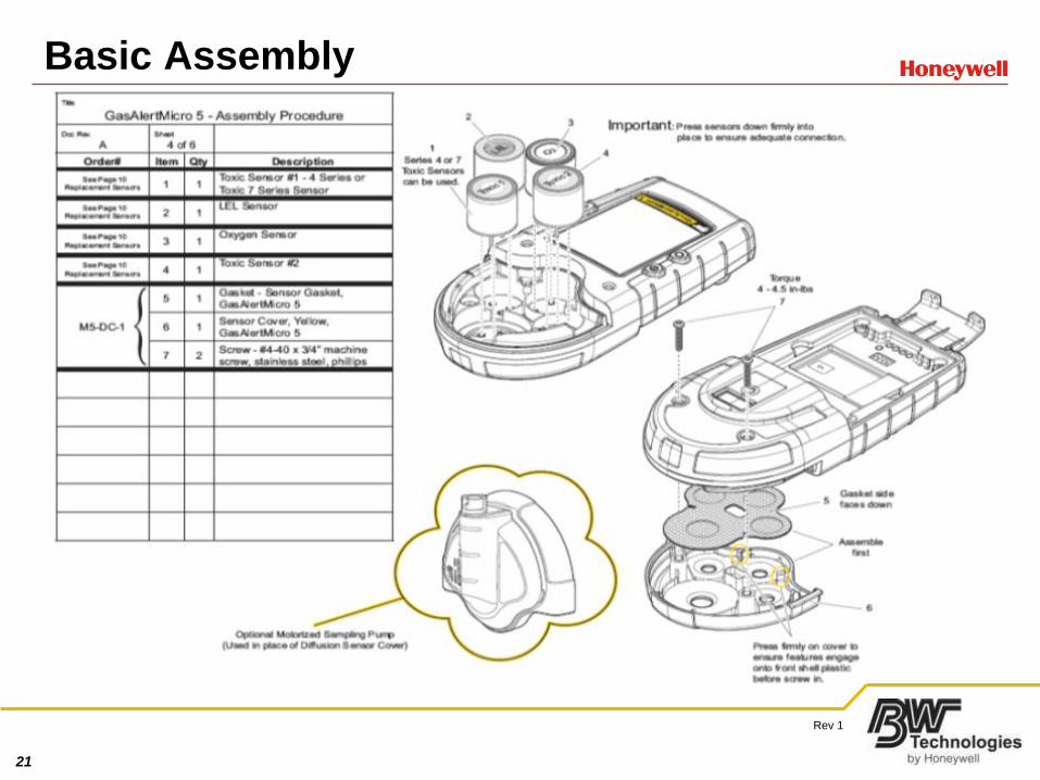
Basic Assembly
22
Rev 1
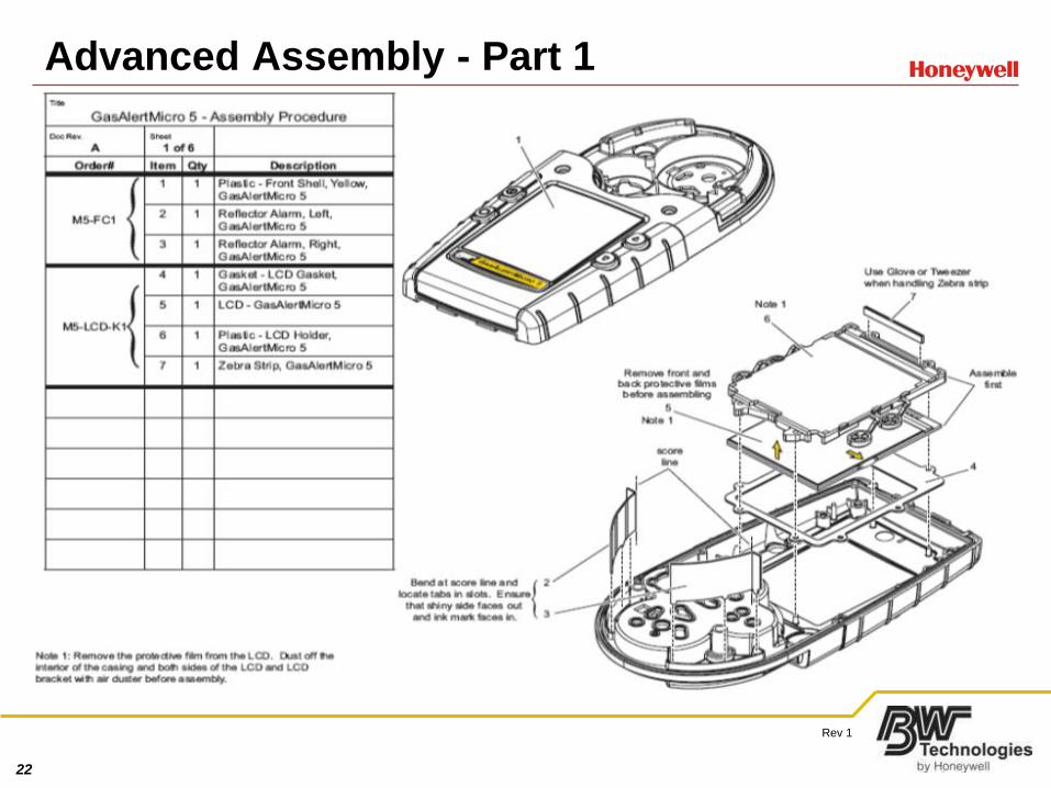
Advanced Assembly - Part 1
23
Rev 1
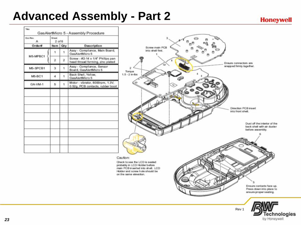
Advanced Assembly - Part 2
24
Rev 1
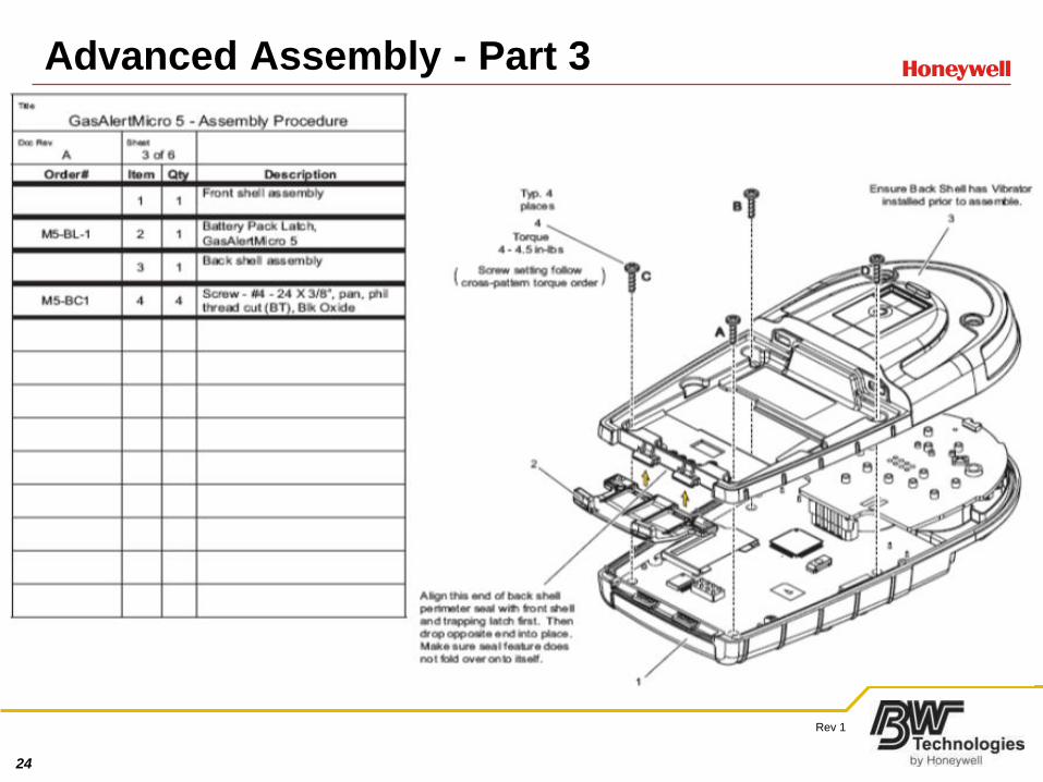
Advanced Assembly - Part 3
25
Rev 1
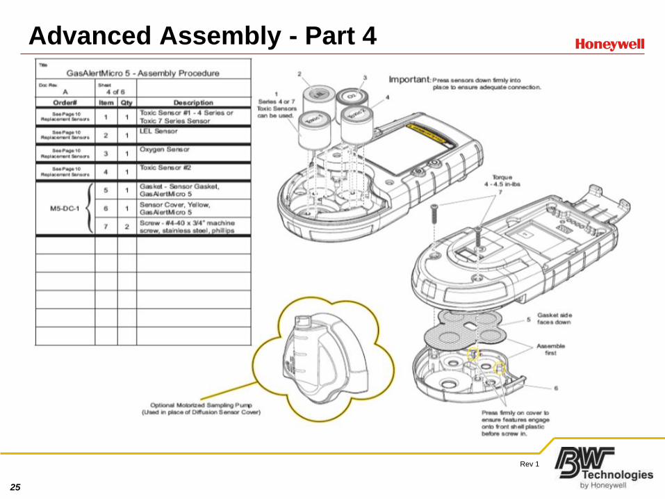
Advanced Assembly - Part 4
26
Rev 1
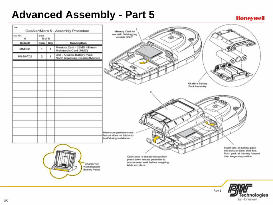
Advanced Assembly - Part 5
27
Rev 1
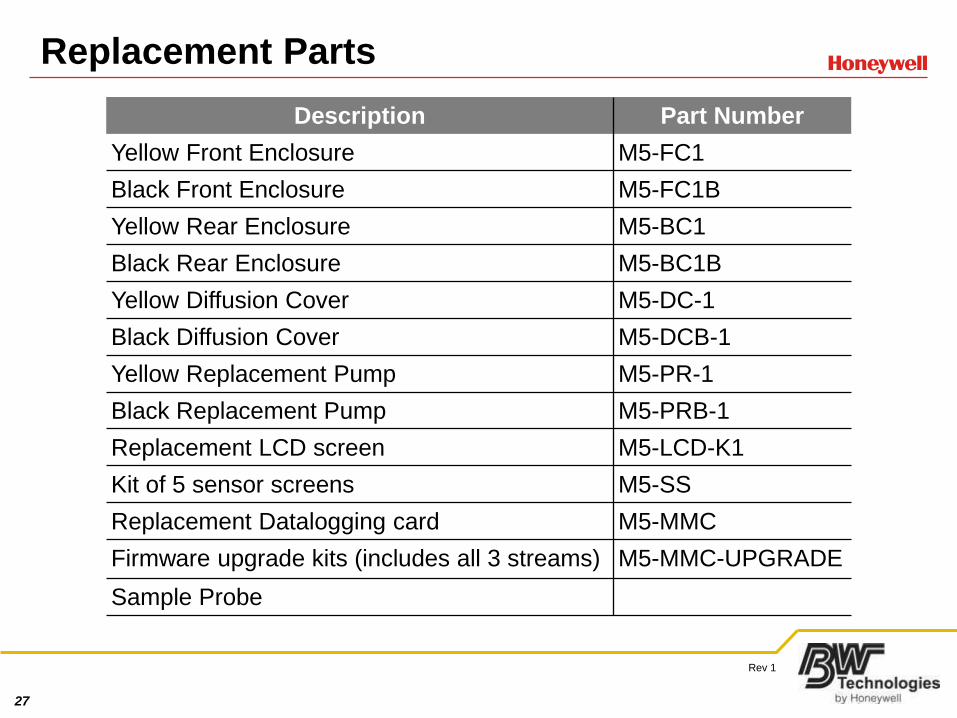
Replacement Parts
Description Part Number
Yellow Front Enclosure M5-FC1
Black Front Enclosure M5-FC1B
Yellow Rear Enclosure M5-BC1
Black Rear Enclosure M5-BC1B
Yellow Diffusion Cover M5-DC-1
Black Diffusion Cover M5-DCB-1
Yellow Replacement Pump M5-PR-1
Black Replacement Pump M5-PRB-1
Replacement LCD screen M5-LCD-K1
Kit of 5 sensor screens M5-SS
Replacement Datalogging card M5-MMC
Firmware upgrade kits (includes all 3 streams) M5-MMC-UPGRADE
Sample Probe
28
Rev 1
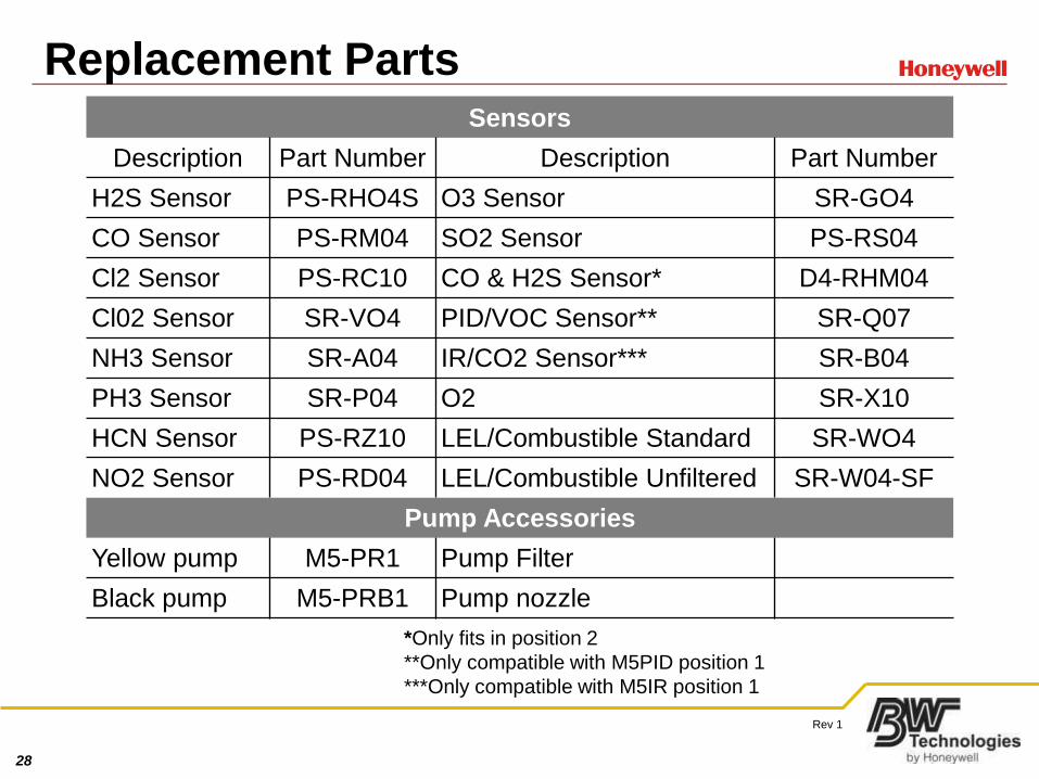
Replacement PartsSensors
Description Part Number Description Part Number
H2S Sensor PS-RHO4S O3 Sensor SR-GO4
CO Sensor PS-RM04 SO2 Sensor PS-RS04
Cl2 Sensor PS-RC10 CO & H2S Sensor* D4-RHM04
Cl02 Sensor SR-VO4 PID/VOC Sensor** SR-Q07
NH3 Sensor SR-A04 IR/CO2 Sensor*** SR-B04
PH3 Sensor SR-P04 O2 SR-X10
HCN Sensor PS-RZ10 LEL/Combustible Standard SR-WO4
NO2 Sensor PS-RD04 LEL/Combustible Unfiltered SR-W04-SF
Pump Accessories
Yellow pump M5-PR1 Pump Filter
Black pump M5-PRB1 Pump nozzle
*Only fits in position 2
**Only compatible with M5PID position 1
***Only compatible with M5IR position 1
29
Rev 1
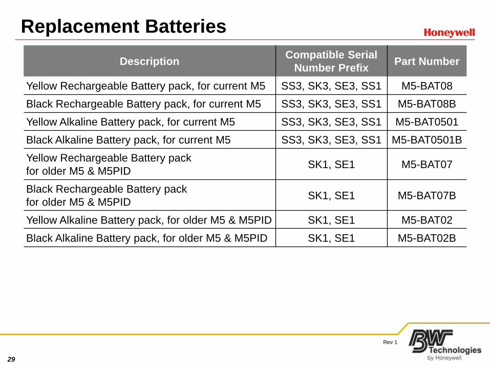
Replacement Batteries
DescriptionCompatible Serial
Number PrefixPart Number
Yellow Rechargeable Battery pack, for current M5 SS3, SK3, SE3, SS1 M5-BAT08
Black Rechargeable Battery pack, for current M5 SS3, SK3, SE3, SS1 M5-BAT08B
Yellow Alkaline Battery pack, for current M5 SS3, SK3, SE3, SS1 M5-BAT0501
Black Alkaline Battery pack, for current M5 SS3, SK3, SE3, SS1 M5-BAT0501B
Yellow Rechargeable Battery pack
for older M5 & M5PIDSK1, SE1 M5-BAT07
Black Rechargeable Battery pack
for older M5 & M5PIDSK1, SE1 M5-BAT07B
Yellow Alkaline Battery pack, for older M5 & M5PID SK1, SE1 M5-BAT02
Black Alkaline Battery pack, for older M5 & M5PID SK1, SE1 M5-BAT02B
30
Rev 1
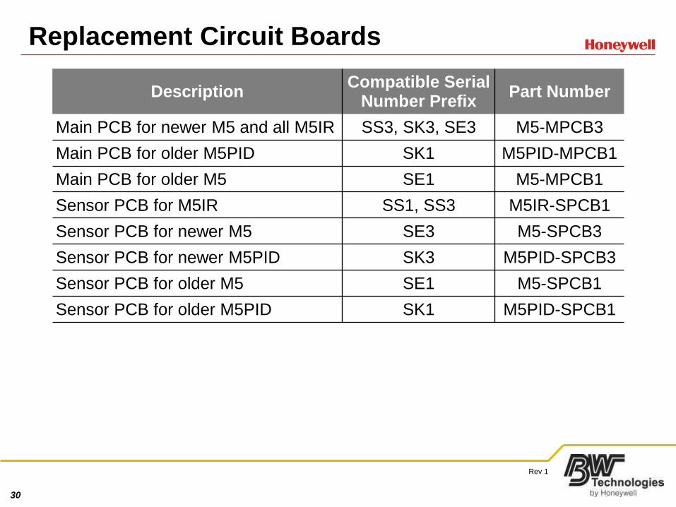
Replacement Circuit Boards
DescriptionCompatible Serial
Number PrefixPart Number
Main PCB for newer M5 and all M5IR SS3, SK3, SE3 M5-MPCB3
Main PCB for older M5PID SK1 M5PID-MPCB1
Main PCB for older M5 SE1 M5-MPCB1
Sensor PCB for M5IR SS1, SS3 M5IR-SPCB1
Sensor PCB for newer M5 SE3 M5-SPCB3
Sensor PCB for newer M5PID SK3 M5PID-SPCB3
Sensor PCB for older M5 SE1 M5-SPCB1
Sensor PCB for older M5PID SK1 M5PID-SPCB1
31
Rev 1
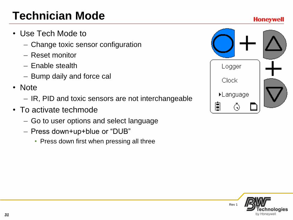
Technician Mode
• Use Tech Mode to
– Change toxic sensor configuration
– Reset monitor
– Enable stealth
– Bump daily and force cal
• Note
– IR, PID and toxic sensors are not interchangeable
• To activate techmode
– Go to user options and select language
– Press down+up+blue or “DUB”
• Press down first when pressing all three
32
Rev 1
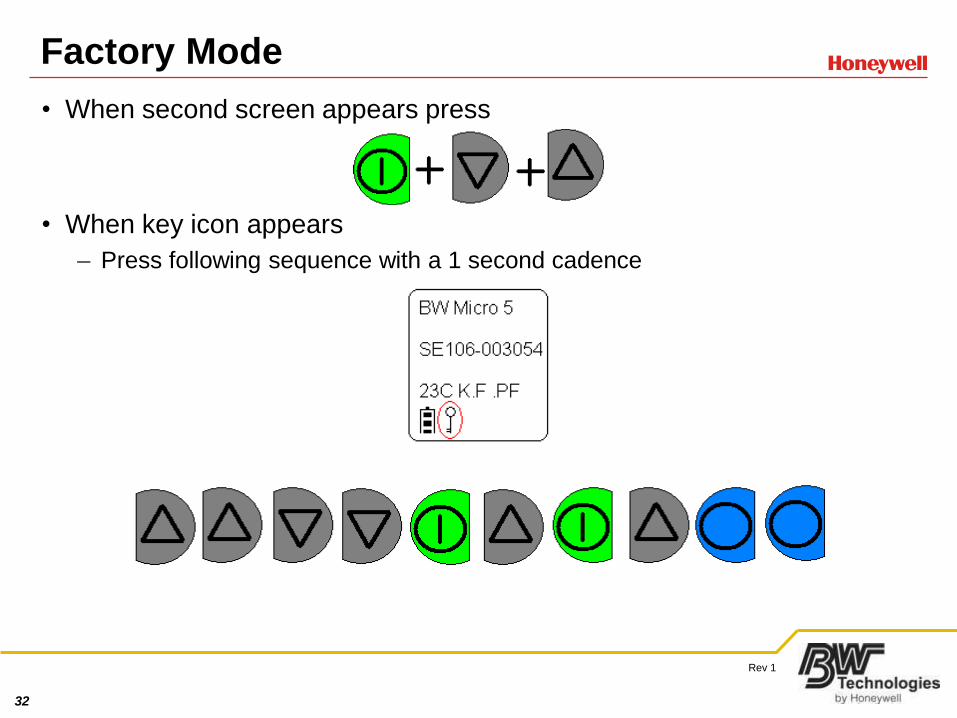
Factory Mode
• When second screen appears press
• When key icon appears
– Press following sequence with a 1 second cadence
33
Rev 1
Using Factory Options
• Serial Numbers
– Use when replacing main circuit boards
• Datalogging
– Enable/disable
• MMC card is required to work
• Upgrading costs $200
• MicroDock
– Enables/disables dock functionality
• Rebirth
– Set to disabled
• Initialize
– Factory reset
• Use when sensors will not zero
• Do not touch any other options
34
Rev 1
Replacing or Changing Sensors
• Remove two bolts near alligator clip
• Remove pump or diffusion cover
• Remove problem sensor
• Install new
• Power up and calibrate
35
Rev 1
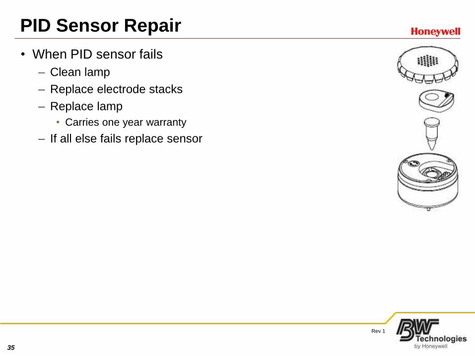
PID Sensor Repair
• When PID sensor fails
– Clean lamp
– Replace electrode stacks
– Replace lamp
• Carries one year warranty
– If all else fails replace sensor
36
Rev 1
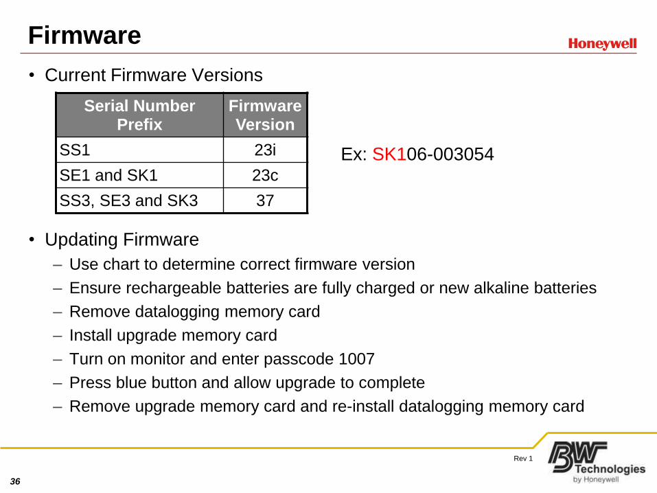
Firmware
• Current Firmware Versions
• Updating Firmware
– Use chart to determine correct firmware version
– Ensure rechargeable batteries are fully charged or new alkaline batteries
– Remove datalogging memory card
– Install upgrade memory card
– Turn on monitor and enter passcode 1007
– Press blue button and allow upgrade to complete
– Remove upgrade memory card and re-install datalogging memory card
Serial Number Prefix
Firmware Version
SS1 23i
SE1 and SK1 23c
SS3, SE3 and SK3 37
Ex: SK106-003054
37
Rev 1
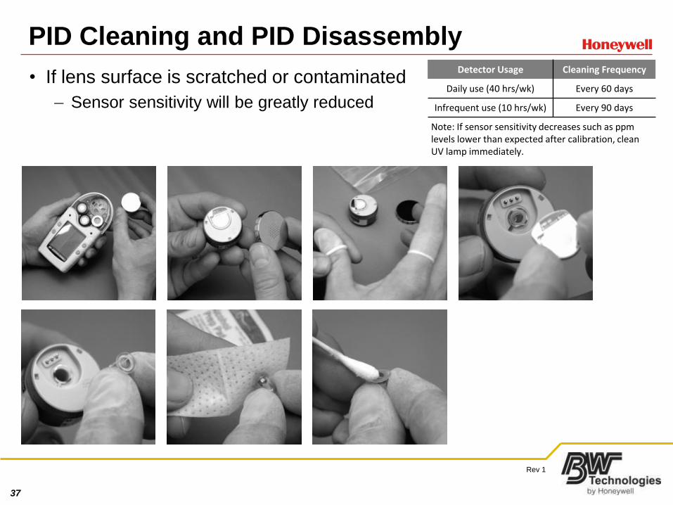
PID Cleaning and PID Disassembly
• If lens surface is scratched or contaminated
– Sensor sensitivity will be greatly reduced
Detector Usage Cleaning Frequency
Daily use (40 hrs/wk) Every 60 days
Infrequent use (10 hrs/wk) Every 90 days
Note: If sensor sensitivity decreases such as ppm levels lower than expected after calibration, clean UV lamp immediately.
38
Rev 1
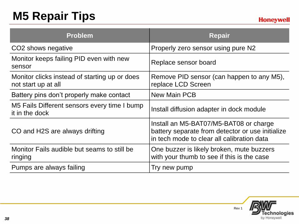
M5 Repair Tips
Problem Repair
CO2 shows negative Properly zero sensor using pure N2
Monitor keeps failing PID even with new sensor
Replace sensor board
Monitor clicks instead of starting up or does not start up at all
Remove PID sensor (can happen to any M5), replace LCD Screen
Battery pins don’t properly make contact New Main PCB
M5 Fails Different sensors every time I bump it in the dock
Install diffusion adapter in dock module
CO and H2S are always driftingInstall an M5-BAT07/M5-BAT08 or charge battery separate from detector or use initialize in tech mode to clear all calibration data
Monitor Fails audible but seams to still be ringing
One buzzer is likely broken, mute buzzers with your thumb to see if this is the case
Pumps are always failing Try new pump
39
Rev 1
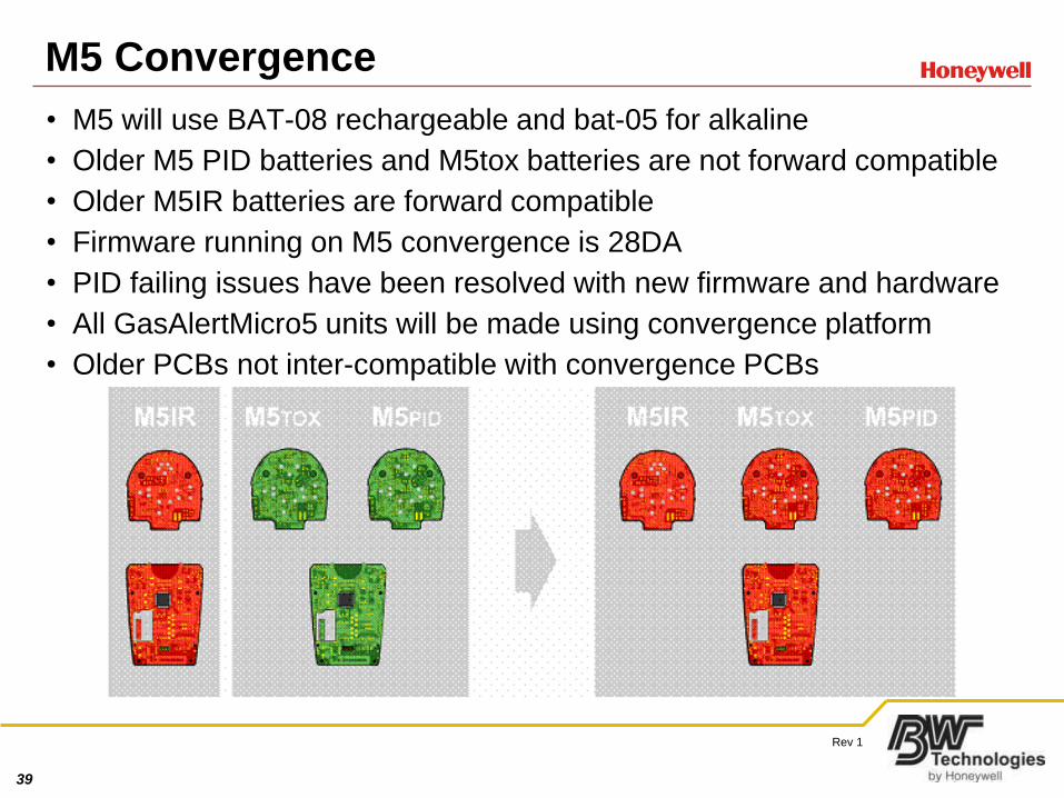
M5 Convergence
• M5 will use BAT-08 rechargeable and bat-05 for alkaline
• Older M5 PID batteries and M5tox batteries are not forward compatible
• Older M5IR batteries are forward compatible
• Firmware running on M5 convergence is 28DA
• PID failing issues have been resolved with new firmware and hardware
• All GasAlertMicro5 units will be made using convergence platform
• Older PCBs not inter-compatible with convergence PCBs
40
Rev 1
Convergence Battery Considerations• Batteries from Pre-Convergence M5 Toxic and M5PID units are not
forward compatible
• Batteries from Pre-Convergence M5IR units are forward compatible with
Convergence based units
• Chargers are still universal
• Batteries compatible with the Convergent M5s are:
M5-BAT08(Lithium Polymer) AND M5-BAT05(Alkaline)
• Batteries compatible with the Pre-Convergent M5s are:
M5-BAT07 (Lithium Polymer) AND M5-BAT02 (Alkaline)
41
Rev 1
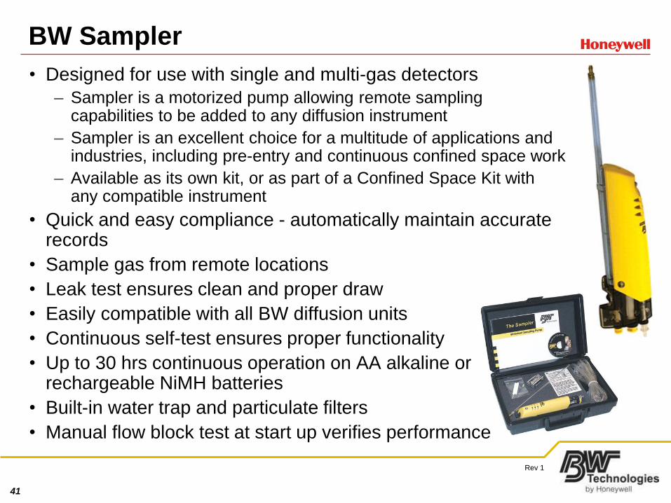
BW Sampler
• Designed for use with single and multi-gas detectors
– Sampler is a motorized pump allowing remote sampling capabilities to be added to any diffusion instrument
– Sampler is an excellent choice for a multitude of applications and industries, including pre-entry and continuous confined space work
– Available as its own kit, or as part of a Confined Space Kit with any compatible instrument
• Quick and easy compliance - automatically maintain accurate records
• Sample gas from remote locations
• Leak test ensures clean and proper draw
• Easily compatible with all BW diffusion units
• Continuous self-test ensures proper functionality
• Up to 30 hrs continuous operation on AA alkaline or rechargeable NiMH batteries
• Built-in water trap and particulate filters
• Manual flow block test at start up verifies performance
42
Rev 1
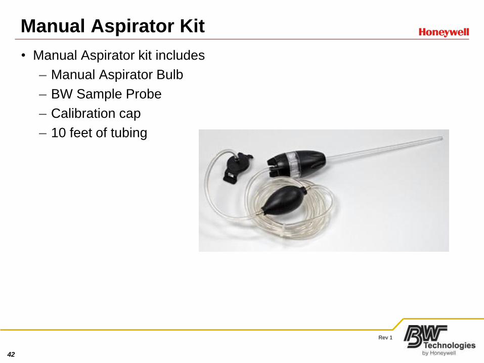
Manual Aspirator Kit
• Manual Aspirator kit includes
– Manual Aspirator Bulb
– BW Sample Probe
– Calibration cap
– 10 feet of tubing
43
Rev 1
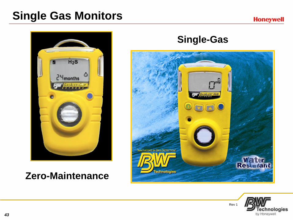
Single Gas Monitors
Single-Gas
Zero-Maintenance
44
Rev 1
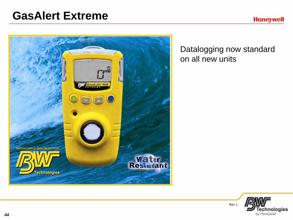
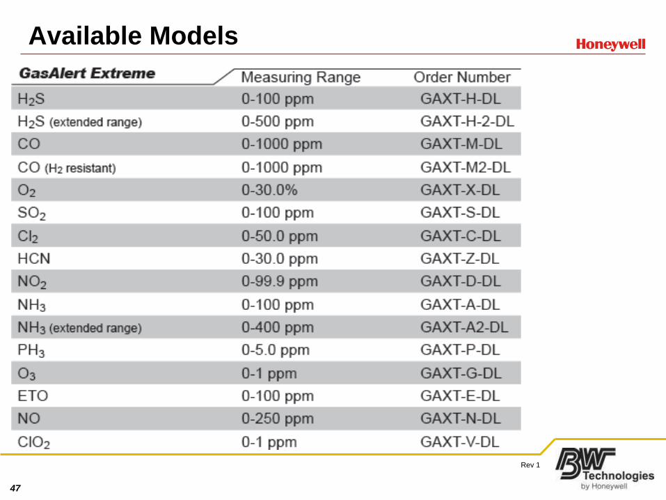
GasAlert Extreme
Datalogging now standard
on all new units
45
Rev 1
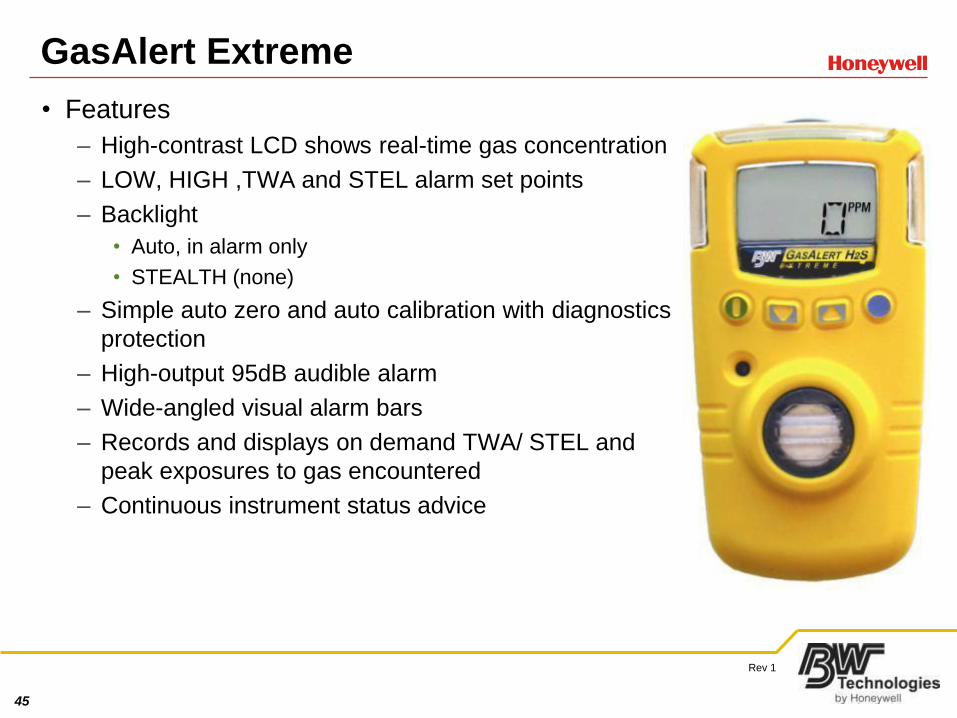
GasAlert Extreme
• Features
– High-contrast LCD shows real-time gas concentration
– LOW, HIGH ,TWA and STEL alarm set points
– Backlight
• Auto, in alarm only
• STEALTH (none)
– Simple auto zero and auto calibration with diagnostics
protection
– High-output 95dB audible alarm
– Wide-angled visual alarm bars
– Records and displays on demand TWA/ STEL and
peak exposures to gas encountered
– Continuous instrument status advice
46
Rev 1
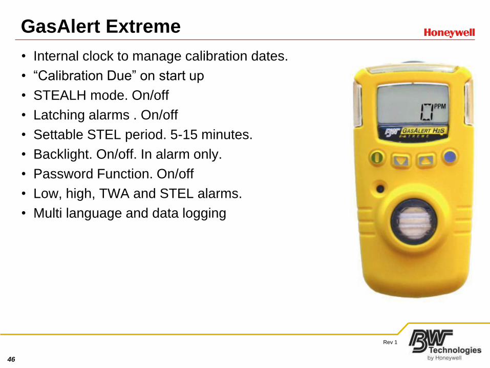
GasAlert Extreme
• Internal clock to manage calibration dates.
• “Calibration Due” on start up
• STEALH mode. On/off
• Latching alarms . On/off
• Settable STEL period. 5-15 minutes.
• Backlight. On/off. In alarm only.
• Password Function. On/off
• Low, high, TWA and STEL alarms.
• Multi language and data logging
47
Rev 1
Available Models
48
Rev 1
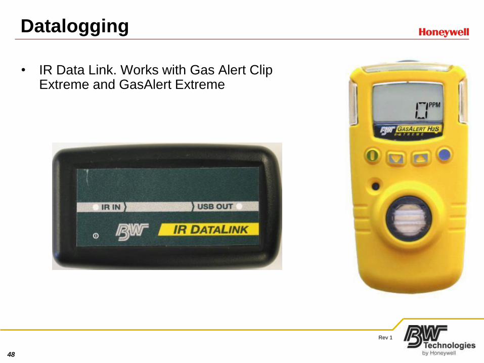
Datalogging
• IR Data Link. Works with Gas Alert Clip Extreme and GasAlert Extreme
49
Rev 1
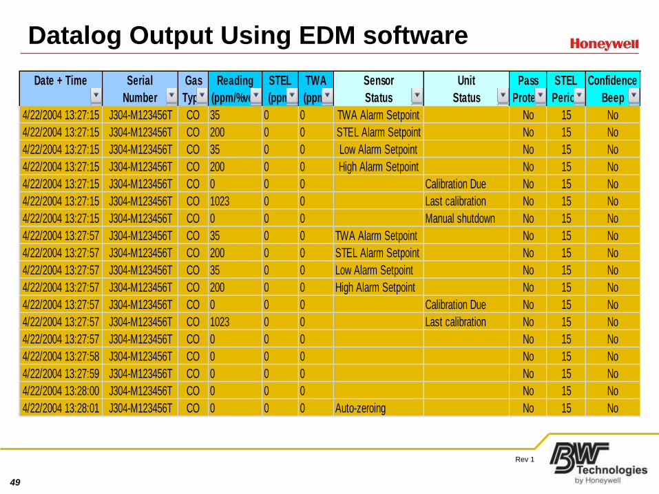
Datalog Output Using EDM software Data logging
Date + Time Serial Gas Reading STEL TWA Sensor Unit Pass STEL Confidence
Number Type (ppm/%vol) (ppm) (ppm) Status Status Protect Period Beep
4/22/2004 13:27:15 J304-M123456T CO 35 0 0 TWA Alarm Setpoint No 15 No
4/22/2004 13:27:15 J304-M123456T CO 200 0 0 STEL Alarm Setpoint No 15 No
4/22/2004 13:27:15 J304-M123456T CO 35 0 0 Low Alarm Setpoint No 15 No
4/22/2004 13:27:15 J304-M123456T CO 200 0 0 High Alarm Setpoint No 15 No
4/22/2004 13:27:15 J304-M123456T CO 0 0 0 Calibration Due No 15 No
4/22/2004 13:27:15 J304-M123456T CO 1023 0 0 Last calibration No 15 No
4/22/2004 13:27:15 J304-M123456T CO 0 0 0 Manual shutdown No 15 No
4/22/2004 13:27:57 J304-M123456T CO 35 0 0 TWA Alarm Setpoint No 15 No
4/22/2004 13:27:57 J304-M123456T CO 200 0 0 STEL Alarm Setpoint No 15 No
4/22/2004 13:27:57 J304-M123456T CO 35 0 0 Low Alarm Setpoint No 15 No
4/22/2004 13:27:57 J304-M123456T CO 200 0 0 High Alarm Setpoint No 15 No
4/22/2004 13:27:57 J304-M123456T CO 0 0 0 Calibration Due No 15 No
4/22/2004 13:27:57 J304-M123456T CO 1023 0 0 Last calibration No 15 No
4/22/2004 13:27:57 J304-M123456T CO 0 0 0 No 15 No
4/22/2004 13:27:58 J304-M123456T CO 0 0 0 No 15 No
4/22/2004 13:27:59 J304-M123456T CO 0 0 0 No 15 No
4/22/2004 13:28:00 J304-M123456T CO 0 0 0 No 15 No
4/22/2004 13:28:01 J304-M123456T CO 0 0 0 Auto-zeroing No 15 No
50
Rev 1
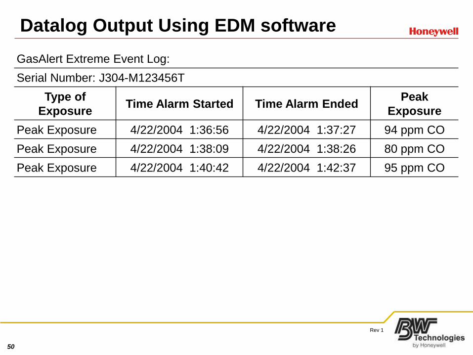
Datalog Output Using EDM softwareEvent logging
GasAlert Extreme Event Log:
Serial Number: J304-M123456T
Type of
ExposureTime Alarm Started Time Alarm Ended
Peak
Exposure
Peak Exposure 4/22/2004 1:36:56 4/22/2004 1:37:27 94 ppm CO
Peak Exposure 4/22/2004 1:38:09 4/22/2004 1:38:26 80 ppm CO
Peak Exposure 4/22/2004 1:40:42 4/22/2004 1:42:37 95 ppm CO
51
Rev 1
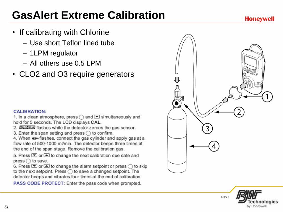
GasAlert Extreme Calibration
• If calibrating with Chlorine
– Use short Teflon lined tube
– 1LPM regulator
– All others use 0.5 LPM
• CLO2 and O3 require generators
52
Rev 1
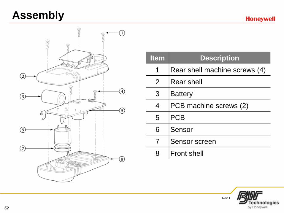
Assembly
Item Description
1 Rear shell machine screws (4)
2 Rear shell
3 Battery
4 PCB machine screws (2)
5 PCB
6 Sensor
7 Sensor screen
8 Front shell
53
Rev 1
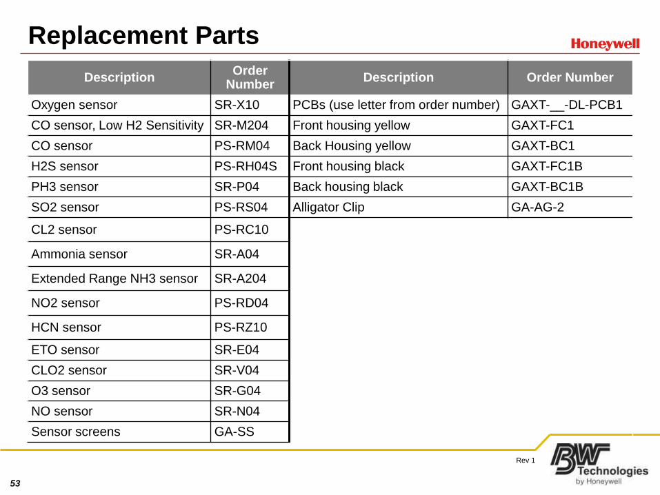
Replacement Parts
Description Order
NumberDescription Order Number
Oxygen sensor SR-X10 PCBs (use letter from order number) GAXT-__-DL-PCB1
CO sensor, Low H2 Sensitivity SR-M204 Front housing yellow GAXT-FC1
CO sensor PS-RM04 Back Housing yellow GAXT-BC1
H2S sensor PS-RH04S Front housing black GAXT-FC1B
PH3 sensor SR-P04 Back housing black GAXT-BC1B
SO2 sensor PS-RS04 Alligator Clip GA-AG-2
CL2 sensor PS-RC10
Ammonia sensor SR-A04
Extended Range NH3 sensor SR-A204
NO2 sensor PS-RD04
HCN sensor PS-RZ10
ETO sensor SR-E04
CLO2 sensor SR-V04
O3 sensor SR-G04
NO sensor SR-N04
Sensor screens GA-SS
54
Rev 1
PCB Replacement
• Secure replacement board
– Replacement board P/N GAXT-__-PCB1
• Fill blank with monitor order number
– Example: Model GAXT-A-DL would use GAXT-A-DL-PCB1
• Disassemble monitor
– Discard old PCB install new PCB
• Reassemble unit
– Apply new serial number labels to back shell
• Power monitor
– Set date and calibrate
55
Rev 1
Battery Replacement
• Use Panasonic Photo CR2 batteries ONLY
• Reset date and calibrate when battery is changed
56
Rev 1
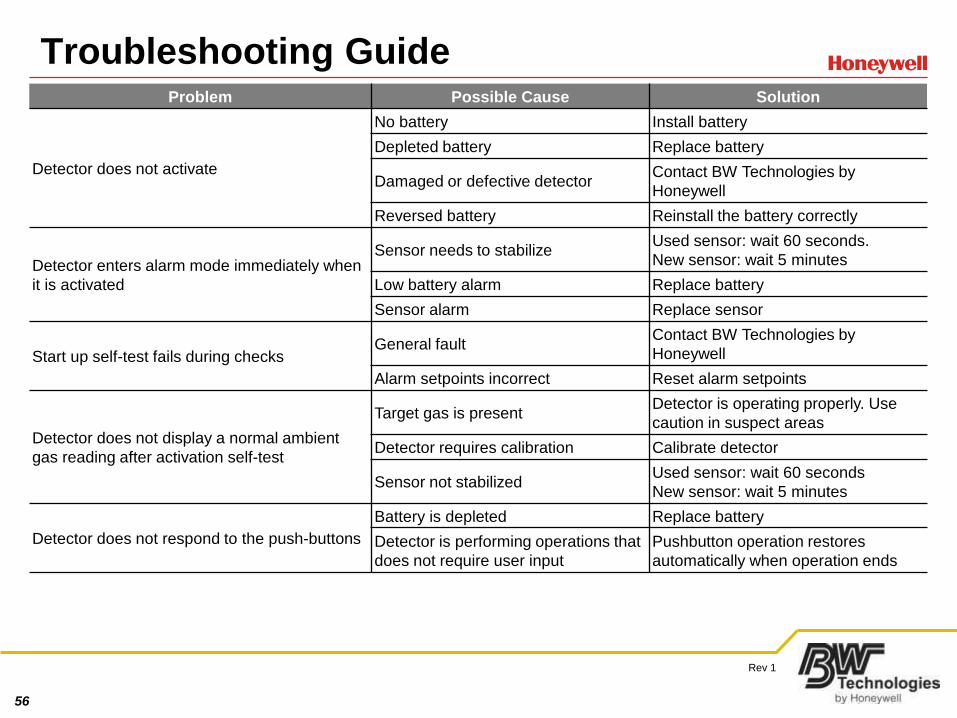
Troubleshooting GuideProblem Possible Cause Solution
Detector does not activate
No battery Install battery
Depleted battery Replace battery
Damaged or defective detector Contact BW Technologies by
Honeywell
Reversed battery Reinstall the battery correctly
Detector enters alarm mode immediately when
it is activated
Sensor needs to stabilize Used sensor: wait 60 seconds.
New sensor: wait 5 minutes
Low battery alarm Replace battery
Sensor alarm Replace sensor
Start up self-test fails during checksGeneral fault
Contact BW Technologies by
Honeywell
Alarm setpoints incorrect Reset alarm setpoints
Detector does not display a normal ambient
gas reading after activation self-test
Target gas is present Detector is operating properly. Use
caution in suspect areas
Detector requires calibration Calibrate detector
Sensor not stabilized Used sensor: wait 60 seconds
New sensor: wait 5 minutes
Detector does not respond to the push-buttons
Battery is depleted Replace battery
Detector is performing operations that
does not require user input
Pushbutton operation restores
automatically when operation ends
57
Rev 1
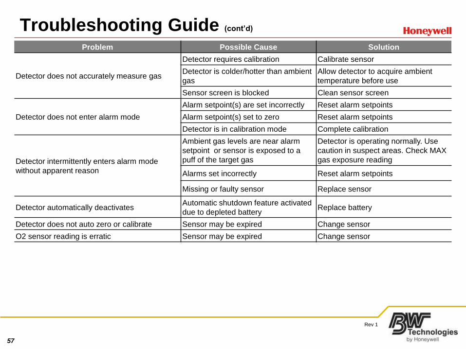
Troubleshooting Guide (cont’d)Problem Possible Cause Solution
Detector does not accurately measure gas
Detector requires calibration Calibrate sensor
Detector is colder/hotter than ambient
gas
Allow detector to acquire ambient
temperature before use
Sensor screen is blocked Clean sensor screen
Detector does not enter alarm mode
Alarm setpoint(s) are set incorrectly Reset alarm setpoints
Alarm setpoint(s) set to zero Reset alarm setpoints
Detector is in calibration mode Complete calibration
Detector intermittently enters alarm mode
without apparent reason
Ambient gas levels are near alarm
setpoint or sensor is exposed to a
puff of the target gas
Detector is operating normally. Use
caution in suspect areas. Check MAX
gas exposure reading
Alarms set incorrectly Reset alarm setpoints
Missing or faulty sensor Replace sensor
Detector automatically deactivatesAutomatic shutdown feature activated
due to depleted battery Replace battery
Detector does not auto zero or calibrate Sensor may be expired Change sensor
O2 sensor reading is erratic Sensor may be expired Change sensor

58
Rev 1
MicroDock II Module
59
Rev 1
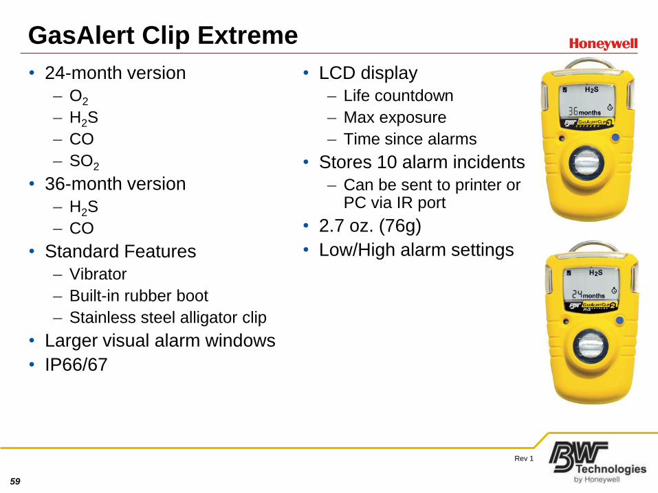
GasAlert Clip Extreme
• 24-month version
– O2
– H2S
– CO
– SO2
• 36-month version
– H2S
– CO
• Standard Features
– Vibrator
– Built-in rubber boot
– Stainless steel alligator clip
• Larger visual alarm windows
• IP66/67
• LCD display
– Life countdown
– Max exposure
– Time since alarms
• Stores 10 alarm incidents
– Can be sent to printer or PC via IR port
• 2.7 oz. (76g)
• Low/High alarm settings
60
Rev 1
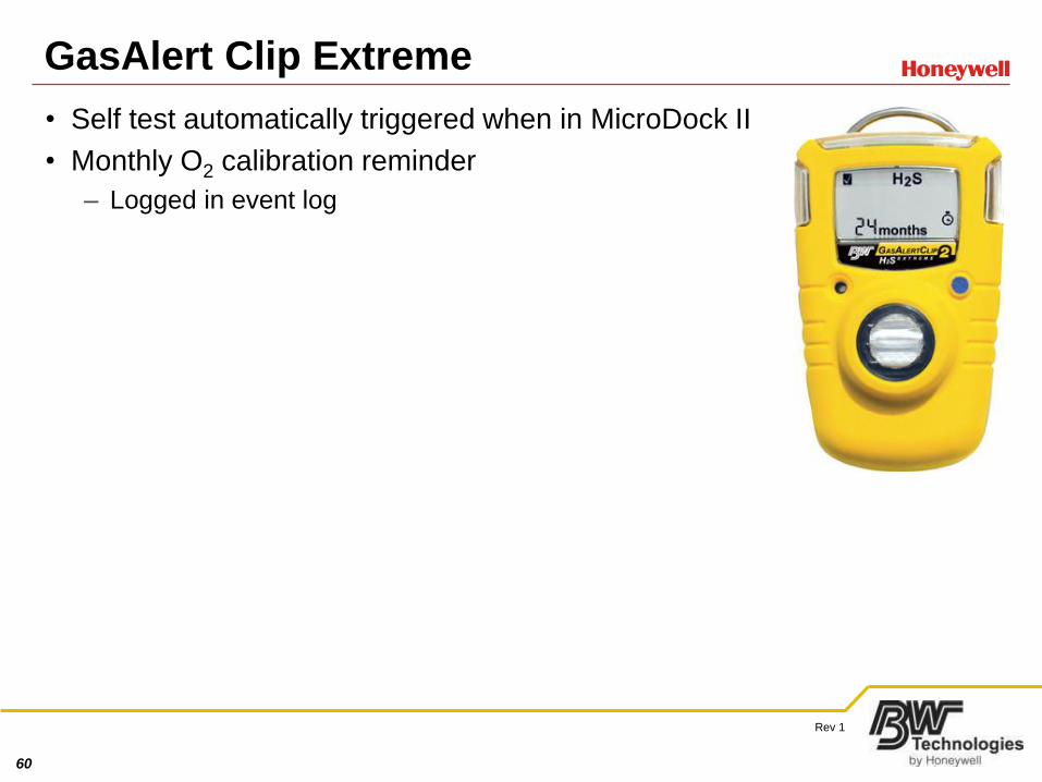
GasAlert Clip Extreme
• Self test automatically triggered when in MicroDock II
• Monthly O2 calibration reminder
– Logged in event log
61
Rev 1
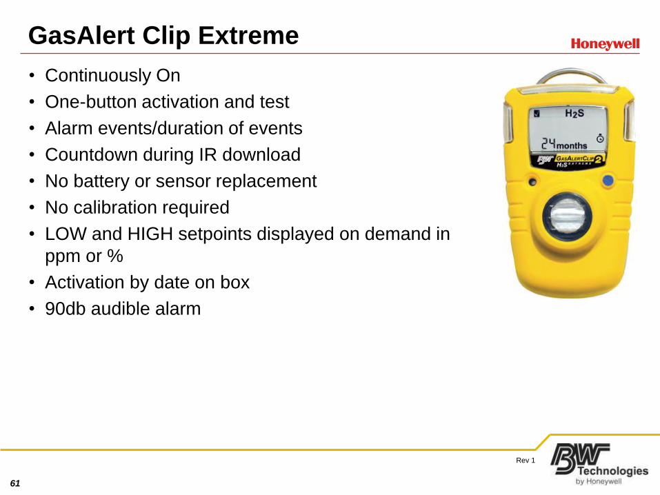
GasAlert Clip Extreme
• Continuously On
• One-button activation and test
• Alarm events/duration of events
• Countdown during IR download
• No battery or sensor replacement
• No calibration required
• LOW and HIGH setpoints displayed on demand in
ppm or %
• Activation by date on box
• 90db audible alarm

62
Rev 1
GasAlert Clip Extreme
• Stores 10 alarm events
– Download via IR Datalink GA-USB2
– MicroDock II - preferred
– Results can be viewed in Fleet Manager II
63
Rev 1
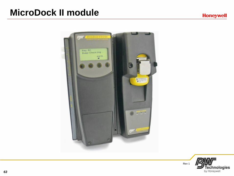
MicroDock II module
64
Rev 1
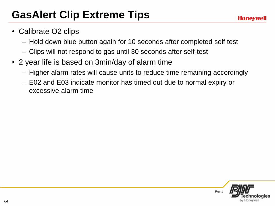
GasAlert Clip Extreme Tips
• Calibrate O2 clips
– Hold down blue button again for 10 seconds after completed self test
– Clips will not respond to gas until 30 seconds after self-test
• 2 year life is based on 3min/day of alarm time
– Higher alarm rates will cause units to reduce time remaining accordingly
– E02 and E03 indicate monitor has timed out due to normal expiry or
excessive alarm time
65
Rev 1
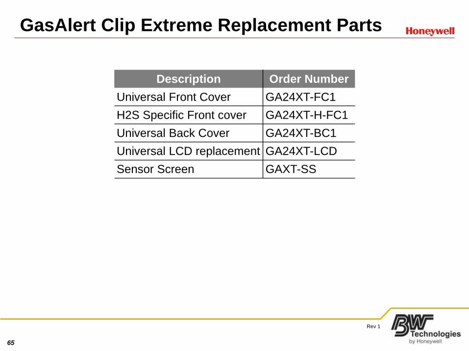
GasAlert Clip Extreme Replacement Parts
Description Order Number
Universal Front Cover GA24XT-FC1
H2S Specific Front cover GA24XT-H-FC1
Universal Back Cover GA24XT-BC1
Universal LCD replacement GA24XT-LCD
Sensor Screen GAXT-SS
66
Rev 1
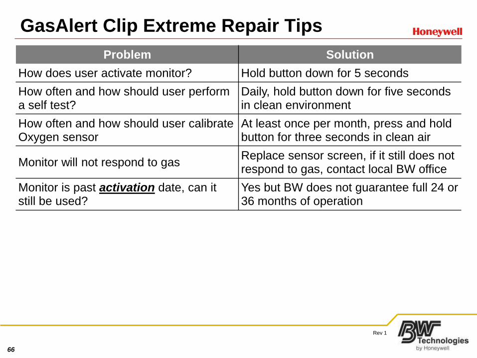
GasAlert Clip Extreme Repair Tips
Problem Solution
How does user activate monitor? Hold button down for 5 seconds
How often and how should user perform a self test?
Daily, hold button down for five seconds in clean environment
How often and how should user calibrate Oxygen sensor
At least once per month, press and hold button for three seconds in clean air
Monitor will not respond to gasReplace sensor screen, if it still does not respond to gas, contact local BW office
Monitor is past activation date, can it still be used?
Yes but BW does not guarantee full 24 or 36 months of operation
67
Rev 1
GasAlert Clip Extreme VE
• Auto-Zero function for low PPM alarms
– New event type added to event log - records when user initiates auto-zero
– Enabled when < 5 ppm for H2S, < 25ppm CO, < 3ppm for SO2
– EDM and IR Data Link don't support new event definition
– Fleet Manager II supports event
• E03 Error code added for too much alarm time
• Button press disabled during alarm condition
• O2 Calibration time changed
• Event log resolution changed
– Resolution for CO is 1ppm from 5
– H2S, SO2 1ppm (no change)
– O2 0.1% (no change)
68
Rev 1
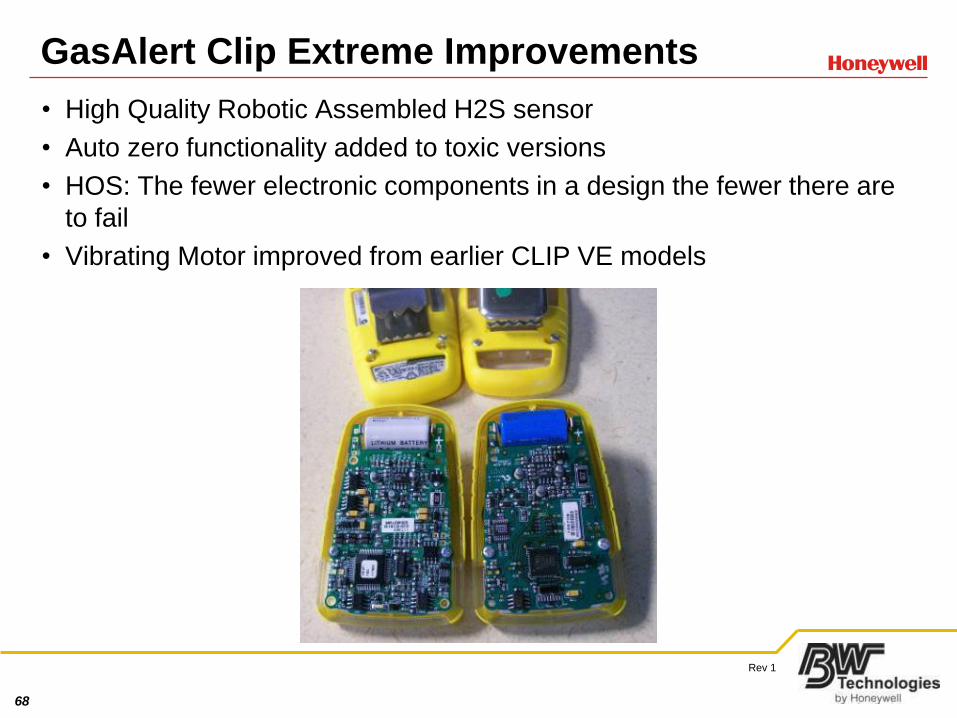
GasAlert Clip Extreme Improvements
• High Quality Robotic Assembled H2S sensor
• Auto zero functionality added to toxic versions
• HOS: The fewer electronic components in a design the fewer there are
to fail
• Vibrating Motor improved from earlier CLIP VE models
69
Rev 1
GasAlert Clip Extreme Improvements (cont’d)
• Lower alarm set points
– Instrument supports fractional alarm set-points
– Alarm setting for H2S below 10 ppm can be fractional (eg 2.5 ppm)
– Fractional alarm set points rounded when transferred to Fleet Manager
• eg 2.4ppm becomes 2ppm, 2.5ppm becomes 3ppm
• Self test can run in background and can fail detector automatically if
sensor fault is detected
– Functionality of user – initiated self test has not changed
– Additional testing is being performed in background without user initiation
– Background self test can fail instrument resulting in E05
70
Rev 1
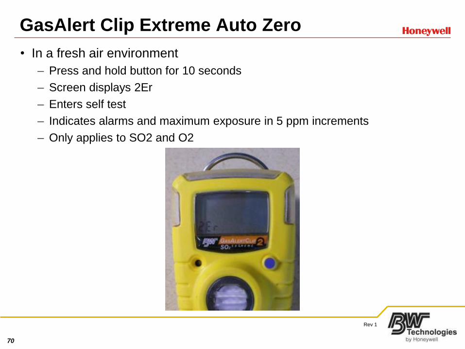
GasAlert Clip Extreme Auto Zero
• In a fresh air environment
– Press and hold button for 10 seconds
– Screen displays 2Er
– Enters self test
– Indicates alarms and maximum exposure in 5 ppm increments
– Only applies to SO2 and O2
71
Rev 1
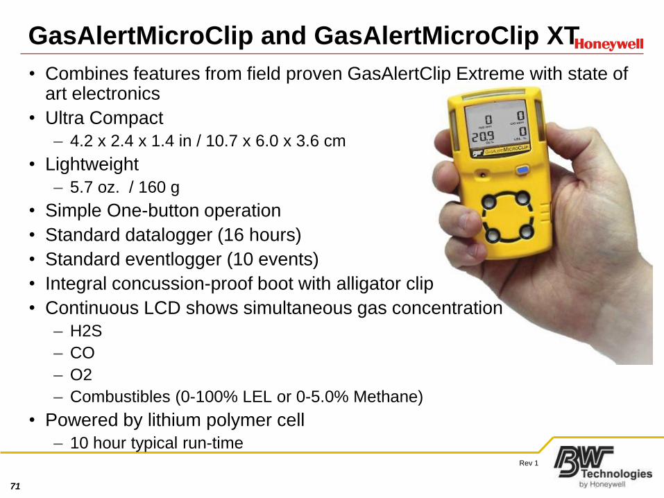
GasAlertMicroClip and GasAlertMicroClip XT
• Combines features from field proven GasAlertClip Extreme with state of art electronics
• Ultra Compact
– 4.2 x 2.4 x 1.4 in / 10.7 x 6.0 x 3.6 cm
• Lightweight
– 5.7 oz. / 160 g
• Simple One-button operation
• Standard datalogger (16 hours)
• Standard eventlogger (10 events)
• Integral concussion-proof boot with alligator clip
• Continuous LCD shows simultaneous gas concentration
– H2S
– CO
– O2
– Combustibles (0-100% LEL or 0-5.0% Methane)
• Powered by lithium polymer cell
– 10 hour typical run-time
72
Rev 1
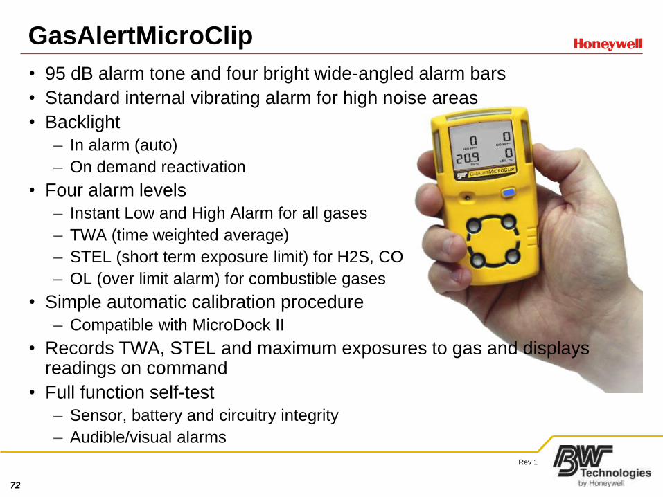
GasAlertMicroClip
• 95 dB alarm tone and four bright wide-angled alarm bars
• Standard internal vibrating alarm for high noise areas
• Backlight
– In alarm (auto)
– On demand reactivation
• Four alarm levels
– Instant Low and High Alarm for all gases
– TWA (time weighted average)
– STEL (short term exposure limit) for H2S, CO
– OL (over limit alarm) for combustible gases
• Simple automatic calibration procedure
– Compatible with MicroDock II
• Records TWA, STEL and maximum exposures to gas and displays readings on command
• Full function self-test
– Sensor, battery and circuitry integrity
– Audible/visual alarms
73
Rev 1
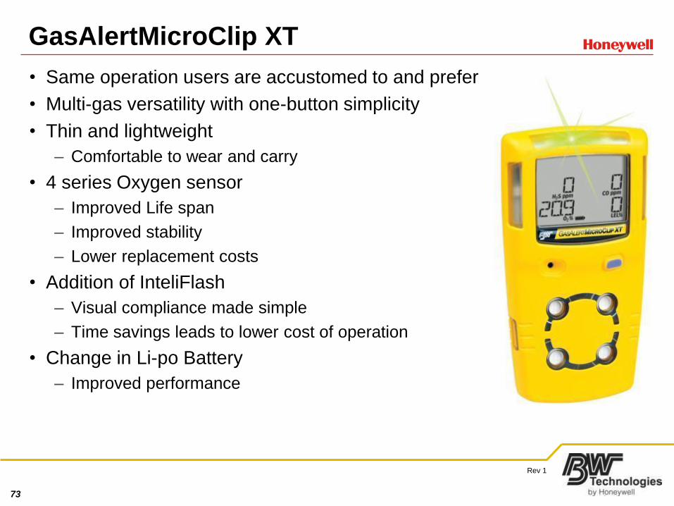
GasAlertMicroClip XT
• Same operation users are accustomed to and prefer
• Multi-gas versatility with one-button simplicity
• Thin and lightweight
– Comfortable to wear and carry
• 4 series Oxygen sensor
– Improved Life span
– Improved stability
– Lower replacement costs
• Addition of InteliFlash
– Visual compliance made simple
– Time savings leads to lower cost of operation
• Change in Li-po Battery
– Improved performance
74
Rev 1
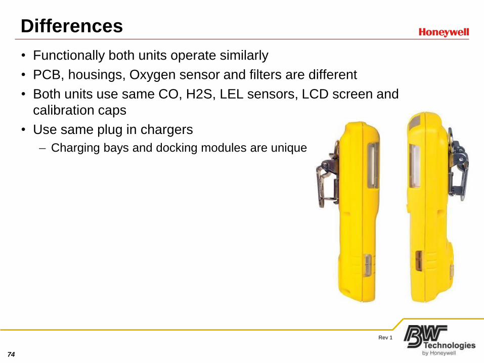
Differences
• Functionally both units operate similarly
• PCB, housings, Oxygen sensor and filters are different
• Both units use same CO, H2S, LEL sensors, LCD screen and
calibration caps
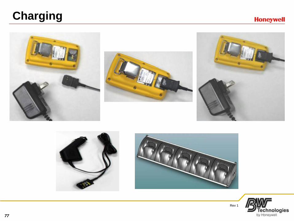
• Use same plug in chargers
– Charging bays and docking modules are unique
75
Rev 1
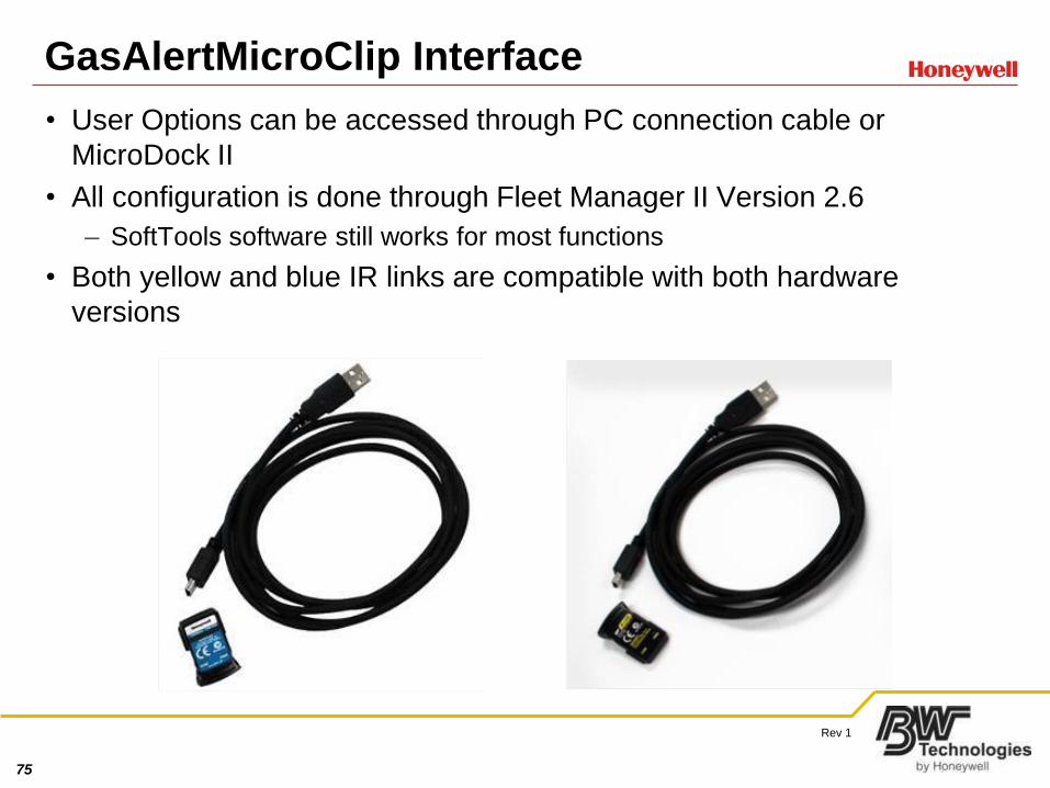
GasAlertMicroClip Interface
• User Options can be accessed through PC connection cable or
MicroDock II
• All configuration is done through Fleet Manager II Version 2.6
– SoftTools software still works for most functions
• Both yellow and blue IR links are compatible with both hardware
versions
76
Rev 1
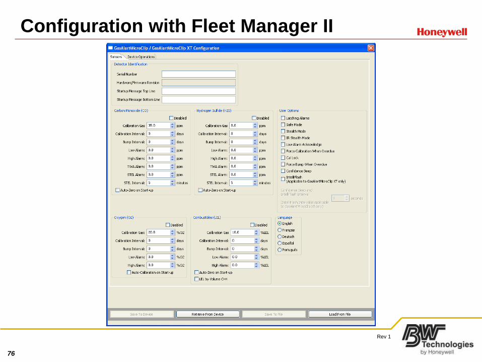
Configuration with Fleet Manager II
77
Rev 1
Charging
78
Rev 1
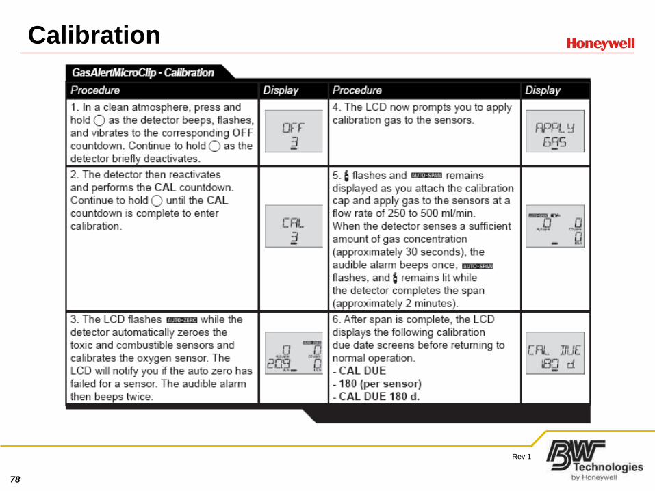
Calibration
79
Rev 1
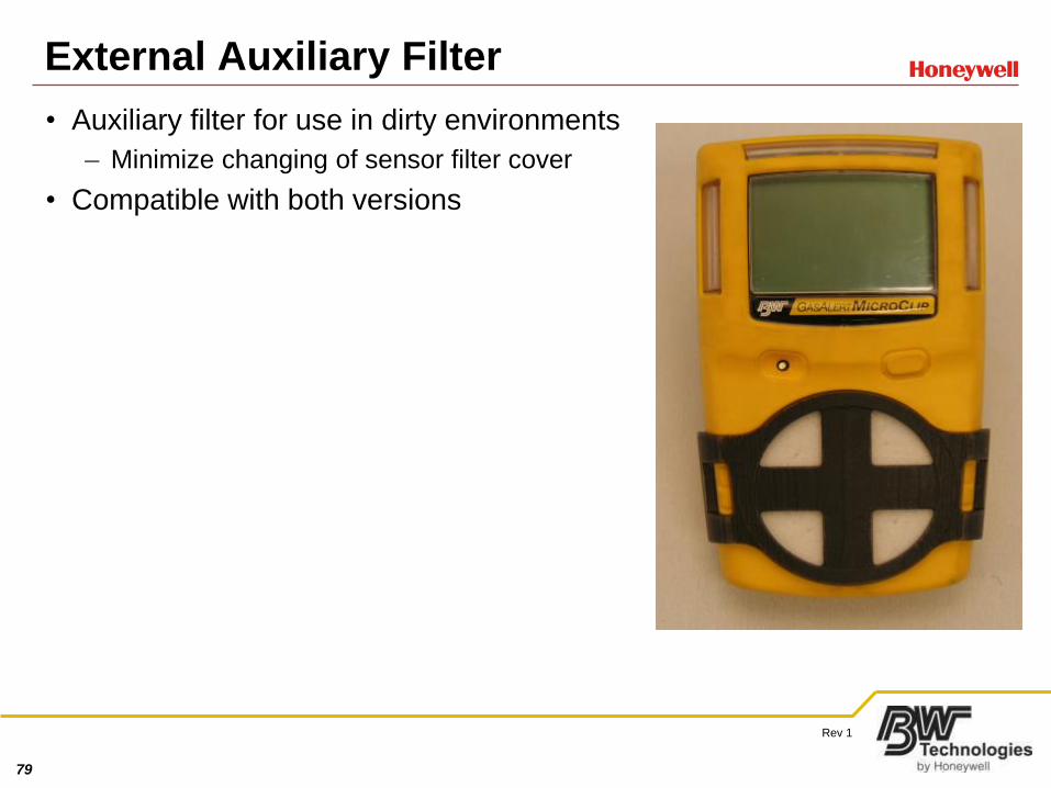
External Auxiliary Filter
• Auxiliary filter for use in dirty environments
– Minimize changing of sensor filter cover
• Compatible with both versions
80
Rev 1
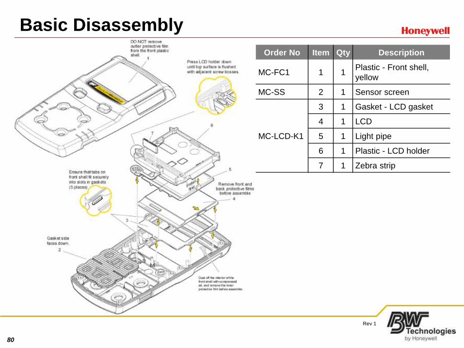
Basic Disassembly
Order No Item Qty Description
MC-FC1 1 1Plastic - Front shell,
yellow
MC-SS 2 1 Sensor screen
MC-LCD-K1
3 1 Gasket - LCD gasket
4 1 LCD
5 1 Light pipe
6 1 Plastic - LCD holder
7 1 Zebra strip
81
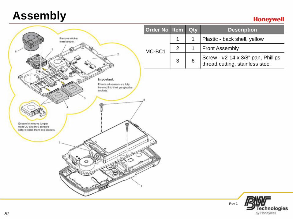
Rev 1
AssemblyOrder No Item Qty Description
MC-BC1
1 1 Plastic - back shell, yellow
2 1 Front Assembly
3 6Screw - #2-14 x 3/8" pan, Phillips
thread cutting, stainless steel
82
Rev 1
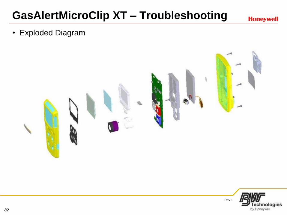
GasAlertMicroClip XT – Troubleshooting
• Exploded Diagram
83
Rev 1
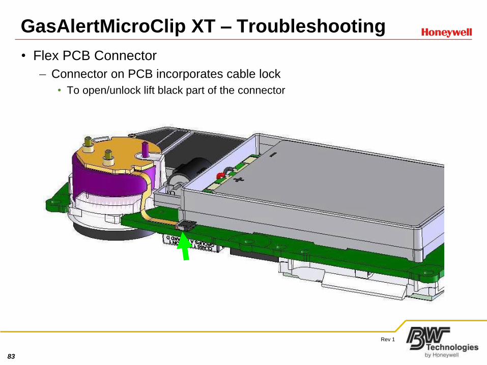
• Flex PCB Connector
– Connector on PCB incorporates cable lock
• To open/unlock lift black part of the connector
GasAlertMicroClip XT – Troubleshooting
84
Rev 1
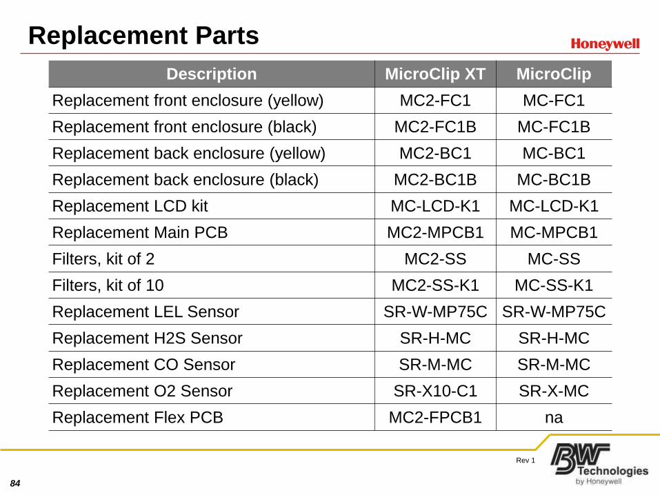
Replacement Parts
Description MicroClip XT MicroClip
Replacement front enclosure (yellow) MC2-FC1 MC-FC1
Replacement front enclosure (black) MC2-FC1B MC-FC1B
Replacement back enclosure (yellow) MC2-BC1 MC-BC1
Replacement back enclosure (black) MC2-BC1B MC-BC1B
Replacement LCD kit MC-LCD-K1 MC-LCD-K1
Replacement Main PCB MC2-MPCB1 MC-MPCB1
Filters, kit of 2 MC2-SS MC-SS
Filters, kit of 10 MC2-SS-K1 MC-SS-K1
Replacement LEL Sensor SR-W-MP75C SR-W-MP75C
Replacement H2S Sensor SR-H-MC SR-H-MC
Replacement CO Sensor SR-M-MC SR-M-MC
Replacement O2 Sensor SR-X10-C1 SR-X-MC
Replacement Flex PCB MC2-FPCB1 na
85
Rev 1
Firmware Upgrade
• Required
– IR connectivity Kit
– Softools v10F or Fleet Manager II
• Power unit
– Connect to IR connectivity kit
• Run Softools
– Execute retrieve from device
– Ensure bottom lights up green
• If firmware version is other than 30B or 11H
– If installed firmware is 30A, 30B or 30C
• Download and unzip 30D from www.gasmonitors.com
– If installed firmware is 11A-11G
• Download and unzip 11H from www.gasmonitors.com
• No updates for GasAlertMicroClip XT at this time
86
Rev 1
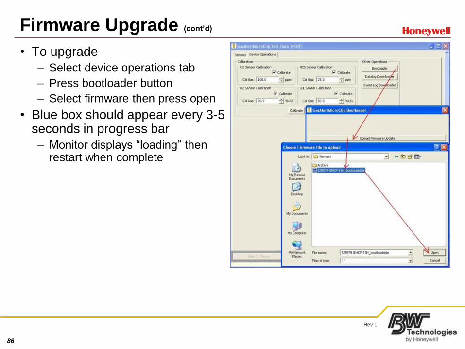
Firmware Upgrade (cont’d)
• To upgrade
– Select device operations tab
– Press bootloader button
– Select firmware then press open
• Blue box should appear every 3-5 seconds in progress bar
– Monitor displays “loading” then restart when complete
87
Rev 1
LEL Sensor Types
• Two types of LEL sensors used in MicroClip and MicroClip XT
– Micropel75/sr-w-mp75
– Micropel40/sr-w-mp
• MICROpel 75C installed in new units and any unit with 30A-30D
firmware
• Micropel40 installed in units built in 2006 and early 2007 or any unit with
11H firmware
– Sensor soon to be obsolete
• Units with serial numbers starting with KA2-4 use Micropel75
– Those starting with KA1 use MICROpel 40
– Firmware is only way to be sure what sensor should be installed
• When Micropel40 sensor is no longer available
– PCB will have to be replaced when sensor needs replacement
• All MicroClipXT units and Max XT units come with and work with SR-W-
MP75
88
Rev 1
Reasons to Replace Circuit Boards
• Failed batteries
• Failed buzzers
• Customers that wish to upgrade from KA1 to KA2 hardware
• Unit will no longer power up
• Bootloader errors
89
Rev 1
PCB Replacement Guide
• Disassemble monitor
– Remove all sensors check for corrosion
• If monitor originally had a micropel40 sensor replace with new
micropel75 (sr-w-mp75) sensor
• Install old sensors in the new PCB and reassemble
• Power monitor
– Should display “IR LOAD Factory”
– Connect to an IR Connectivity kit
• “Retrieve from device”
– Serial number field should be blank
– Enter monitor’s serial number and “save to device”
• Softools should light up green and monitor should start up
• Bump and calibrate
90
Rev 1
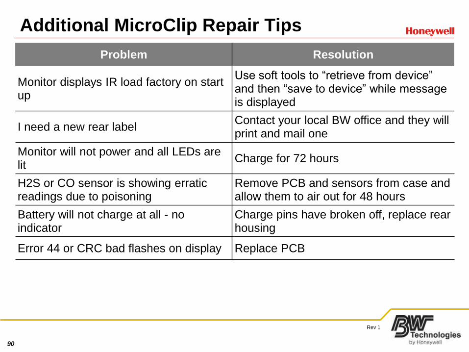
Additional MicroClip Repair Tips
Problem Resolution
Monitor displays IR load factory on start up
Use soft tools to “retrieve from device” and then “save to device” while message is displayed
I need a new rear labelContact your local BW office and they will print and mail one
Monitor will not power and all LEDs are lit
Charge for 72 hours
H2S or CO sensor is showing erratic readings due to poisoning
Remove PCB and sensors from case and allow them to air out for 48 hours
Battery will not charge at all - no indicator
Charge pins have broken off, replace rear housing
Error 44 or CRC bad flashes on display Replace PCB

91
Rev 1
91
92
Rev 1
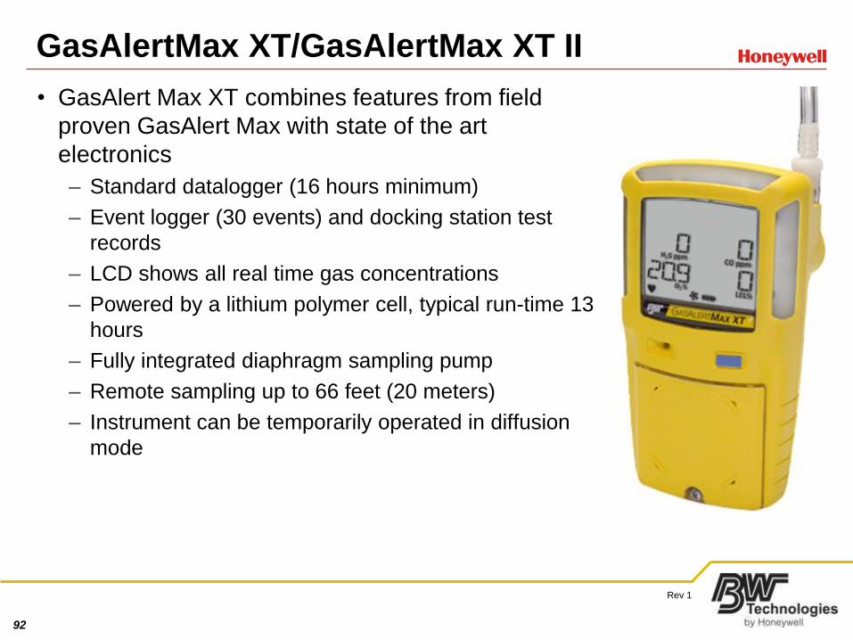
GasAlertMax XT/GasAlertMax XT II
• GasAlert Max XT combines features from field
proven GasAlert Max with state of the art
electronics
– Standard datalogger (16 hours minimum)
– Event logger (30 events) and docking station test
records
– LCD shows all real time gas concentrations
– Powered by a lithium polymer cell, typical run-time 13
hours
– Fully integrated diaphragm sampling pump
– Remote sampling up to 66 feet (20 meters)
– Instrument can be temporarily operated in diffusion
mode
93
Rev 1
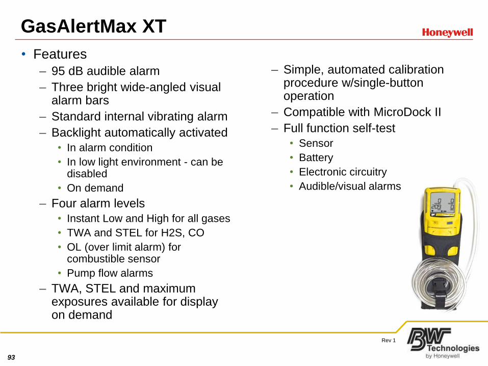
GasAlertMax XT
• Features
– 95 dB audible alarm
– Three bright wide-angled visual alarm bars
– Standard internal vibrating alarm
– Backlight automatically activated
• In alarm condition
• In low light environment - can be disabled
• On demand
– Four alarm levels
• Instant Low and High for all gases
• TWA and STEL for H2S, CO
• OL (over limit alarm) for combustible sensor
• Pump flow alarms
– TWA, STEL and maximum exposures available for display on demand
– Simple, automated calibration procedure w/single-button operation
– Compatible with MicroDock II
– Full function self-test
• Sensor
• Battery
• Electronic circuitry
• Audible/visual alarms
94
Rev 1
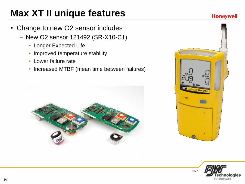
Max XT II unique features
• Change to new O2 sensor includes
– New O2 sensor 121492 (SR-X10-C1)
• Longer Expected Life
• Improved temperature stability
• Lower failure rate
• Increased MTBF (mean time between failures)
95
Rev 1
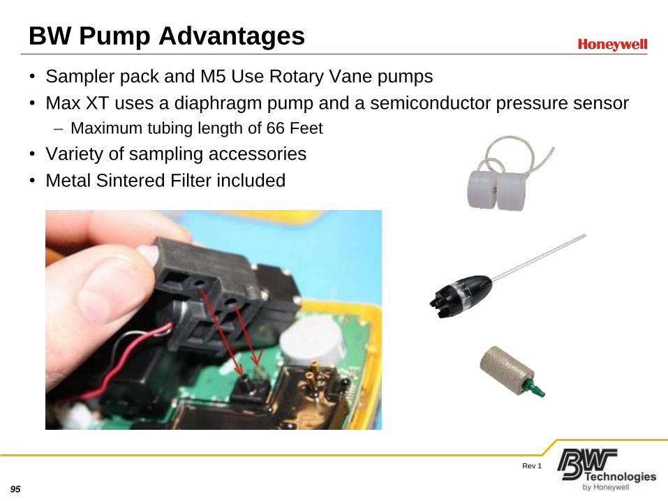
BW Pump Advantages
• Sampler pack and M5 Use Rotary Vane pumps
• Max XT uses a diaphragm pump and a semiconductor pressure sensor
– Maximum tubing length of 66 Feet
• Variety of sampling accessories
• Metal Sintered Filter included
96
Rev 1
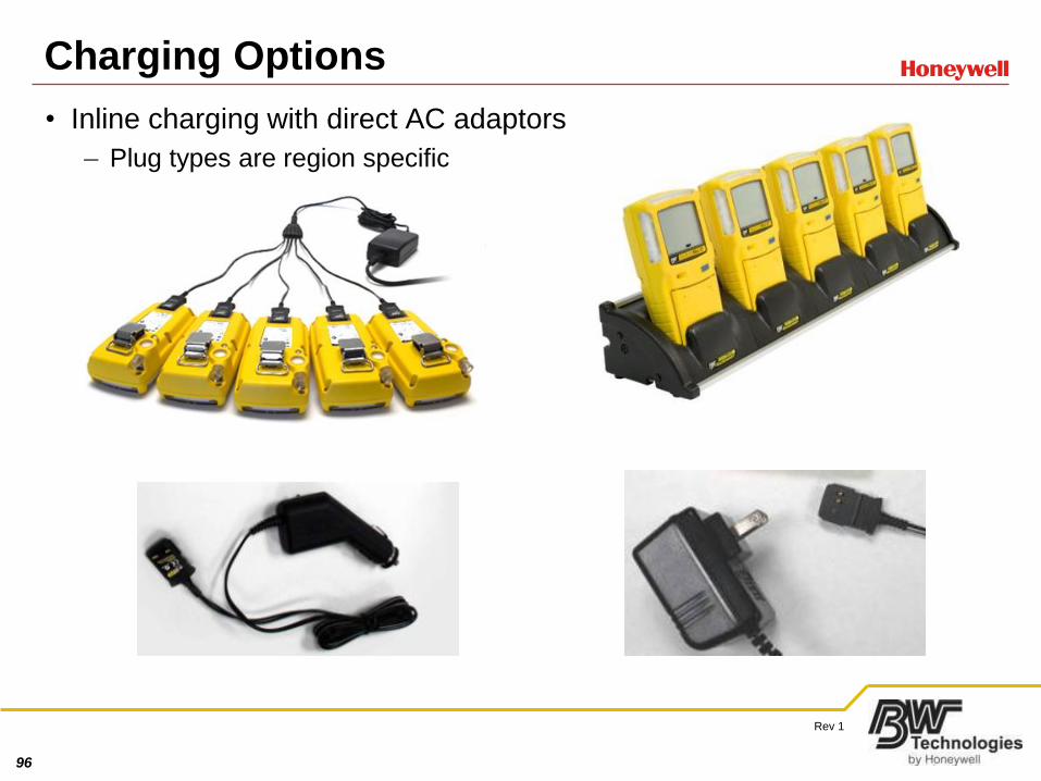
Charging Options
• Inline charging with direct AC adaptors
– Plug types are region specific
97
Rev 1
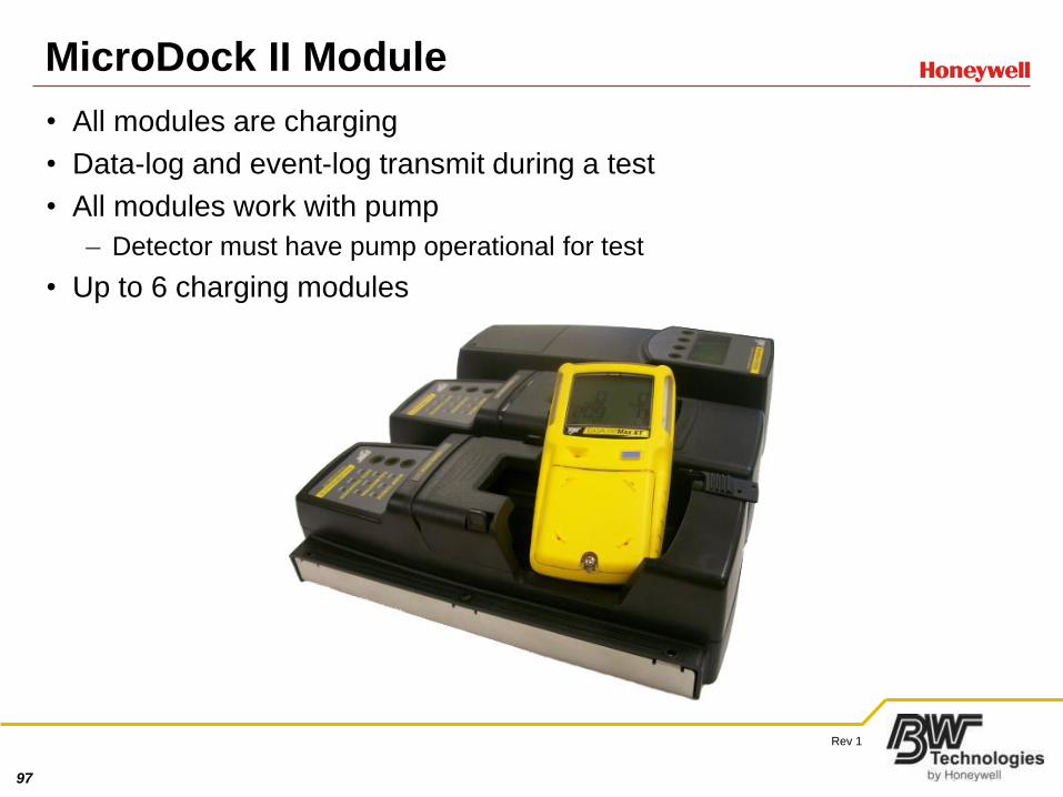
MicroDock II Module
• All modules are charging
• Data-log and event-log transmit during a test
• All modules work with pump
– Detector must have pump operational for test
• Up to 6 charging modules
98
Rev 1
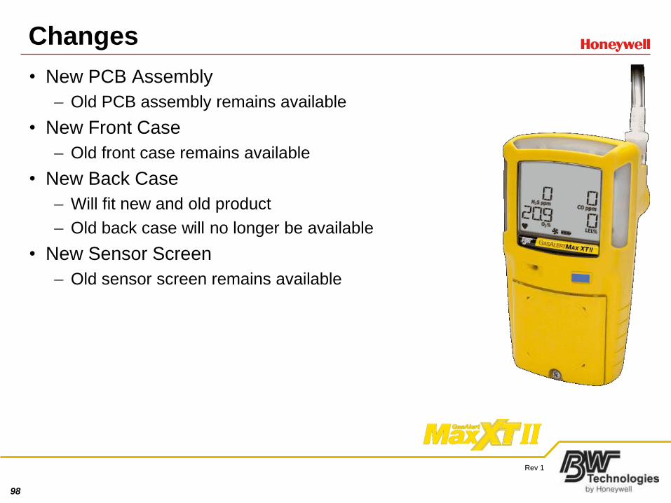
Changes
• New PCB Assembly
– Old PCB assembly remains available
• New Front Case
– Old front case remains available
• New Back Case
– Will fit new and old product
– Old back case will no longer be available
• New Sensor Screen
– Old sensor screen remains available
99
Rev 1
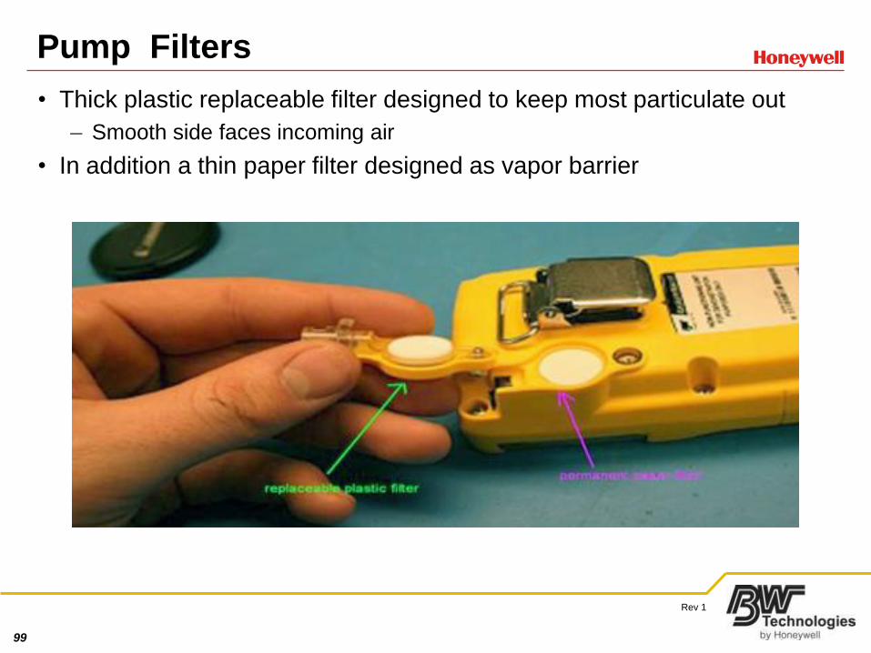
Pump Filters
• Thick plastic replaceable filter designed to keep most particulate out
– Smooth side faces incoming air
• In addition a thin paper filter designed as vapor barrier
100
Rev 1
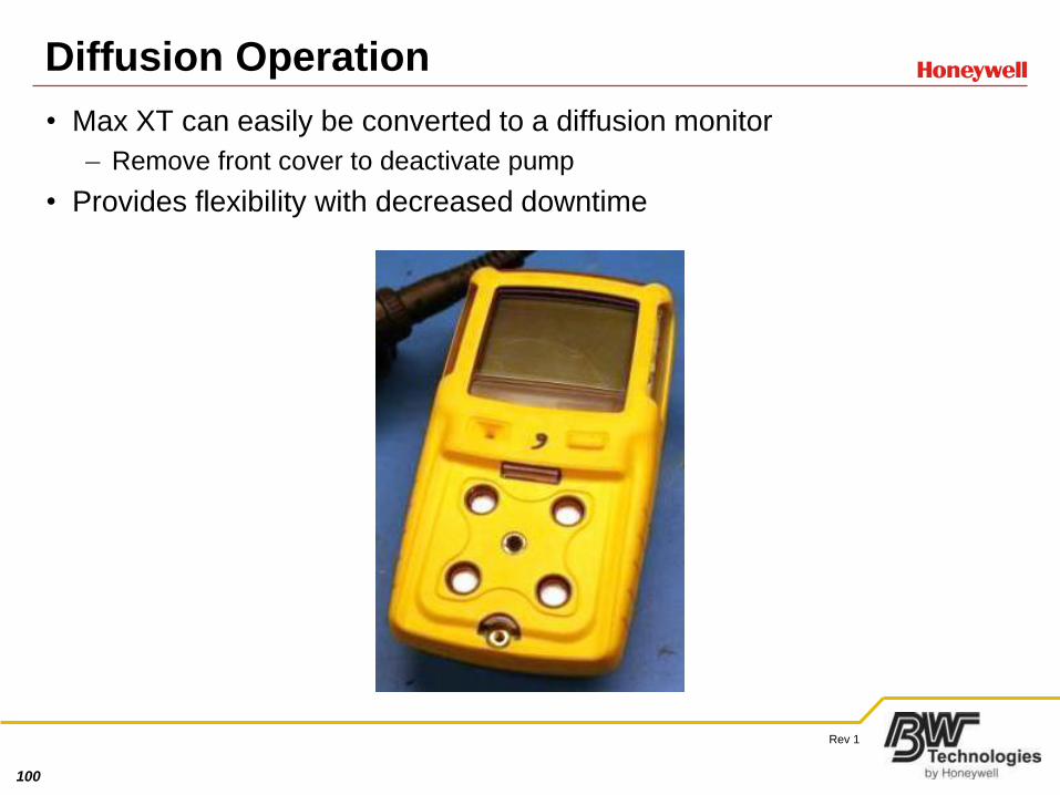
Diffusion Operation
• Max XT can easily be converted to a diffusion monitor
– Remove front cover to deactivate pump
• Provides flexibility with decreased downtime
101
Rev 1
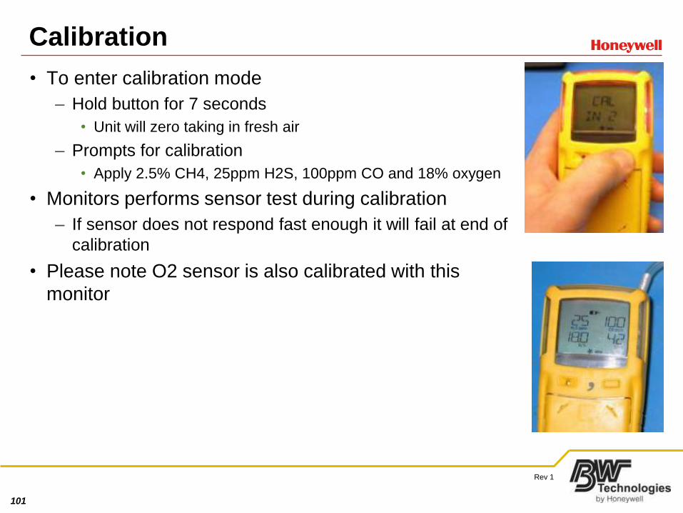
Calibration
• To enter calibration mode
– Hold button for 7 seconds
• Unit will zero taking in fresh air
– Prompts for calibration
• Apply 2.5% CH4, 25ppm H2S, 100ppm CO and 18% oxygen
• Monitors performs sensor test during calibration
– If sensor does not respond fast enough it will fail at end of
calibration
• Please note O2 sensor is also calibrated with this
monitor
102
Rev 1
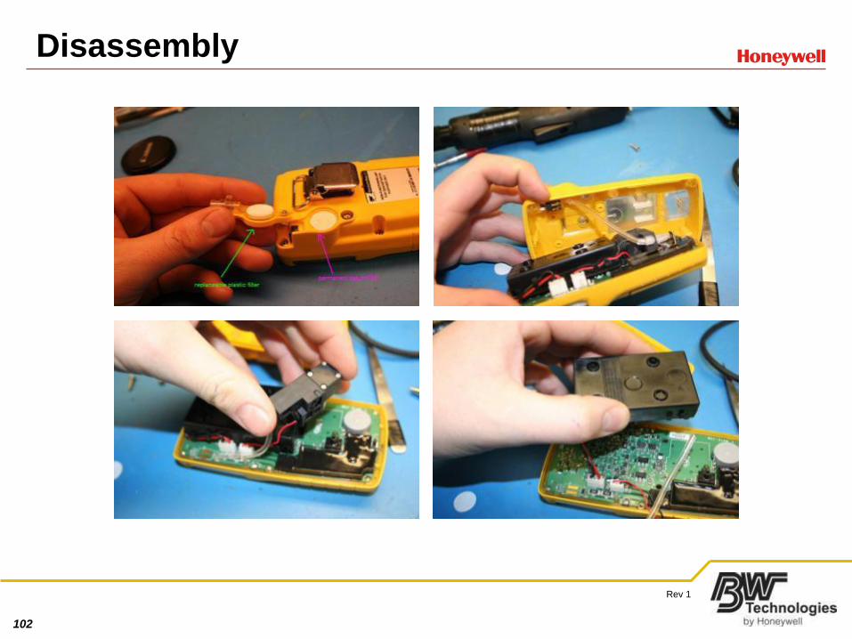
Disassembly

103
Rev 1
Disassembly 2
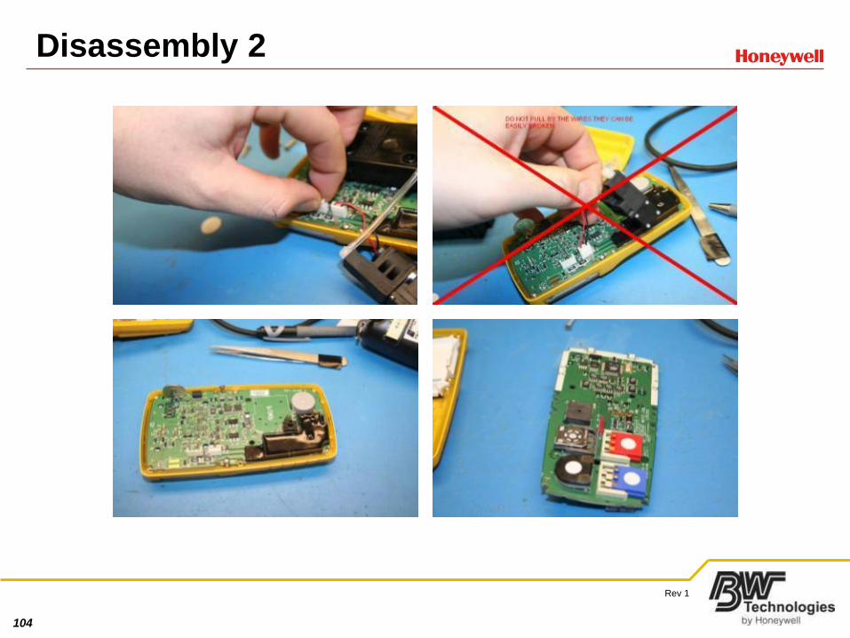
104
Rev 1
Disassembly 2
105
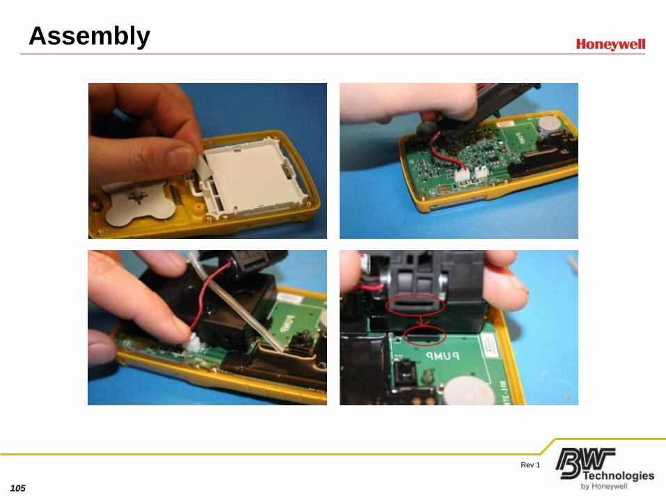
Rev 1
Assembly
106
Rev 1
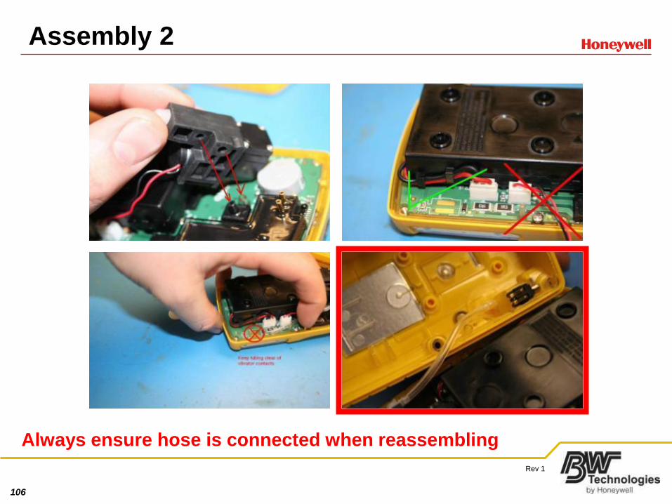
Assembly 2
Always ensure hose is connected when reassembling
107
Rev 1
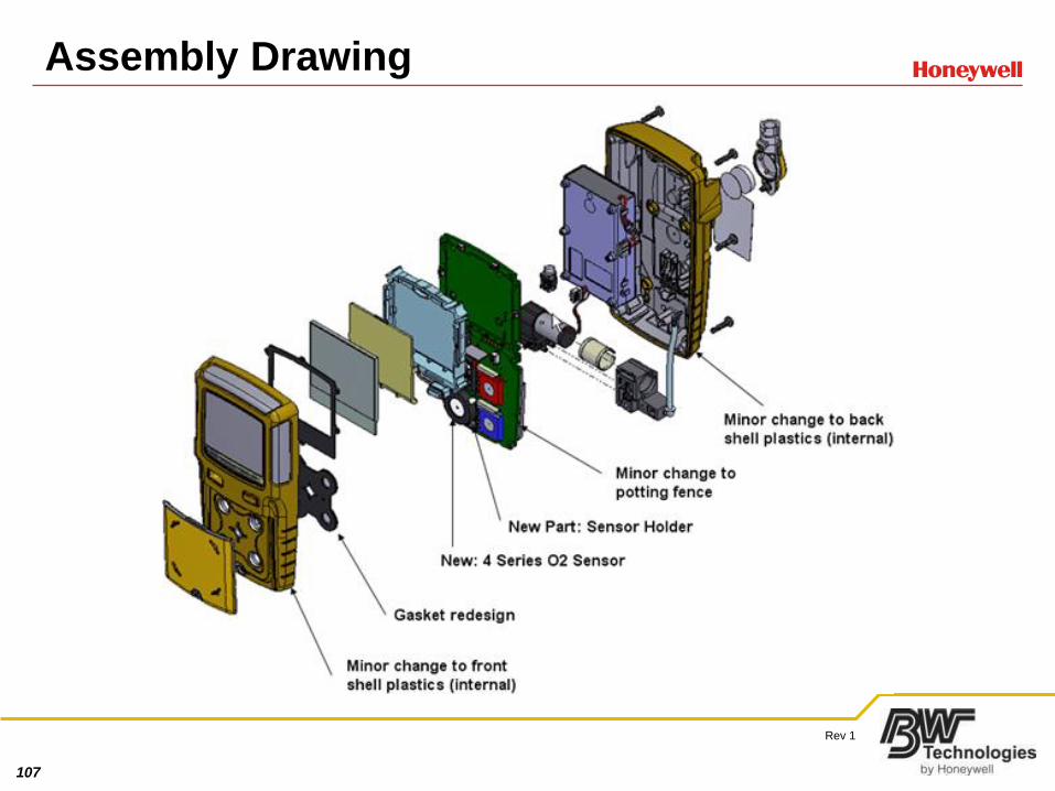
Assembly Drawing
108
Rev 1
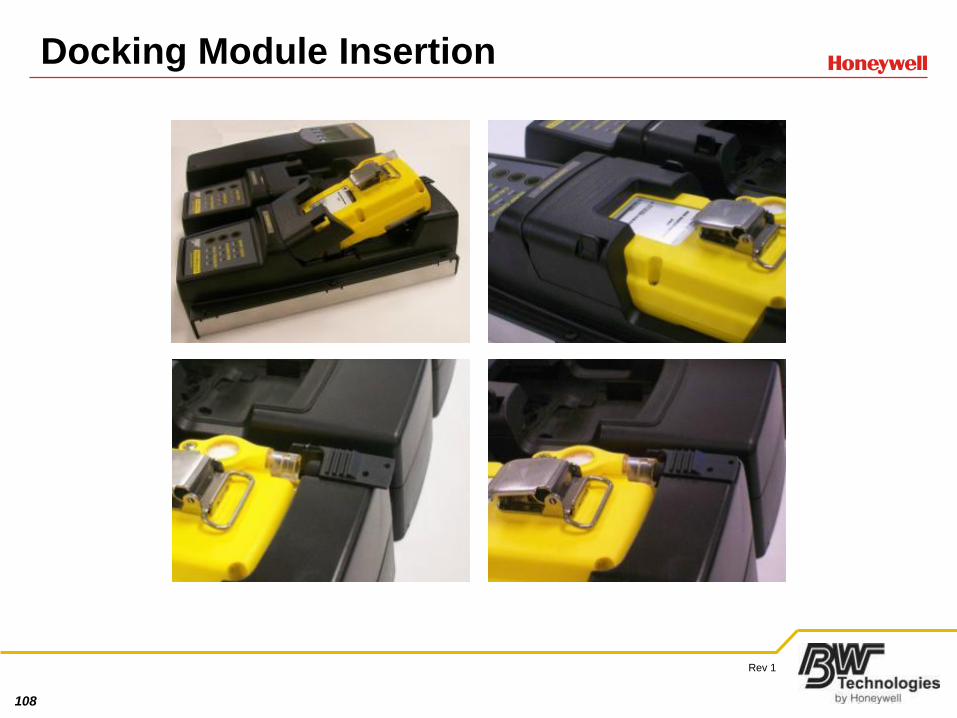
Docking Module Insertion
109
Rev 1
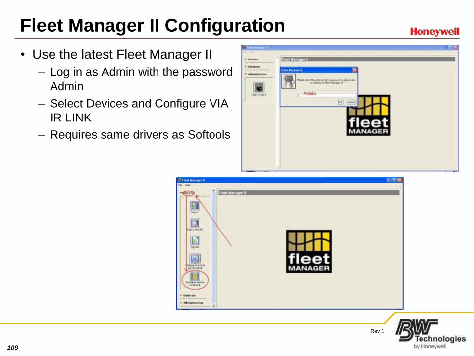
Fleet Manager II Configuration
• Use the latest Fleet Manager II
– Log in as Admin with the password
Admin
– Select Devices and Configure VIA
IR LINK
– Requires same drivers as Softools
110
Rev 1
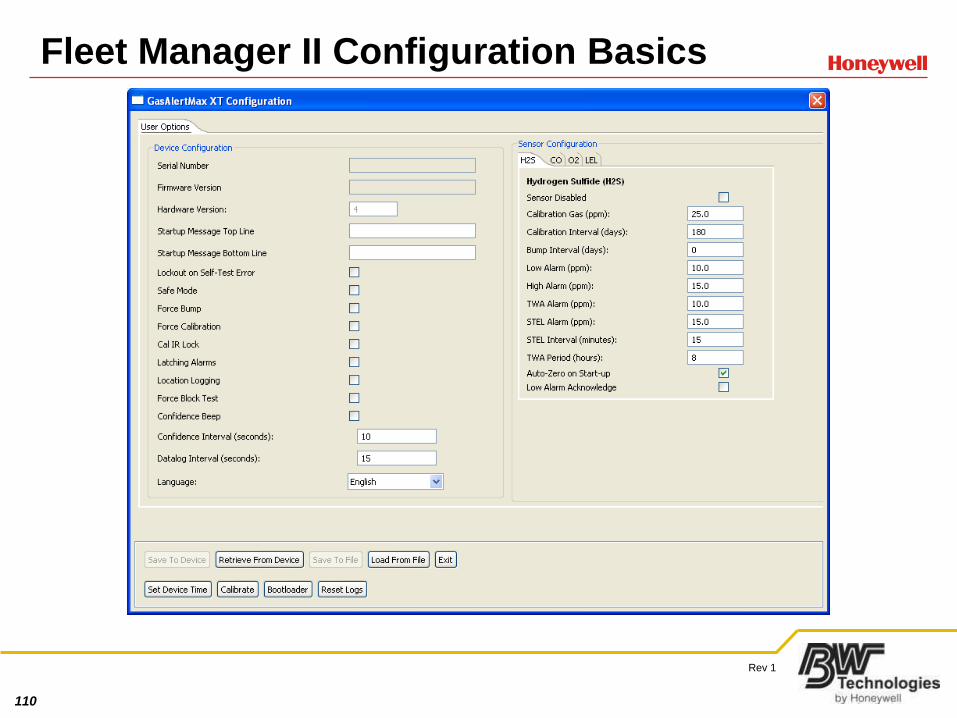
Fleet Manager II Configuration Basics
111
Rev 1
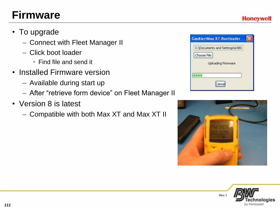
Firmware
• To upgrade
– Connect with Fleet Manager II
– Click boot loader
• Find file and send it
• Installed Firmware version
– Available during start up
– After “retrieve form device” on Fleet Manager II
• Version 8 is latest
– Compatible with both Max XT and Max XT II
112
Rev 1
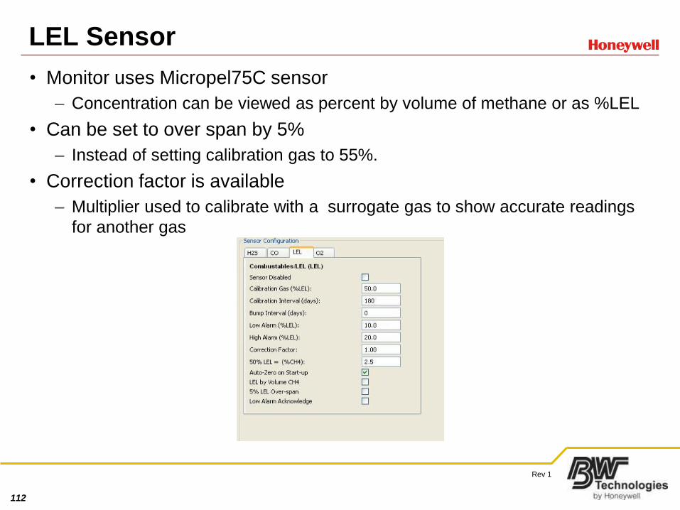
LEL Sensor
• Monitor uses Micropel75C sensor
– Concentration can be viewed as percent by volume of methane or as %LEL
• Can be set to over span by 5%
– Instead of setting calibration gas to 55%.
• Correction factor is available
– Multiplier used to calibrate with a surrogate gas to show accurate readings
for another gas
113
Rev 1
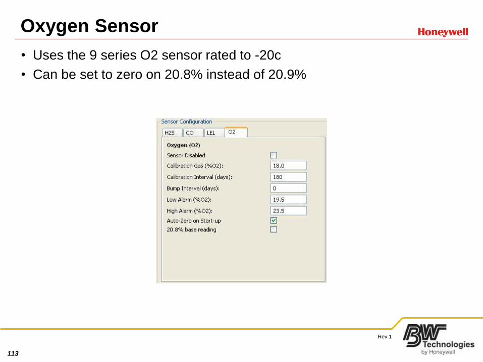
Oxygen Sensor
• Uses the 9 series O2 sensor rated to -20c
• Can be set to zero on 20.8% instead of 20.9%
114
Rev 1
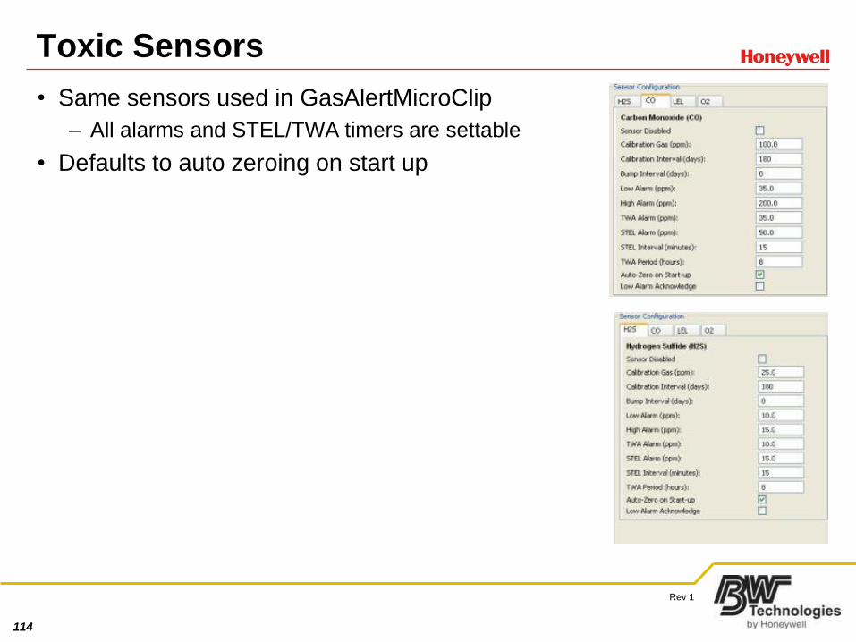
Toxic Sensors
• Same sensors used in GasAlertMicroClip
– All alarms and STEL/TWA timers are settable
• Defaults to auto zeroing on start up
115
Rev 1
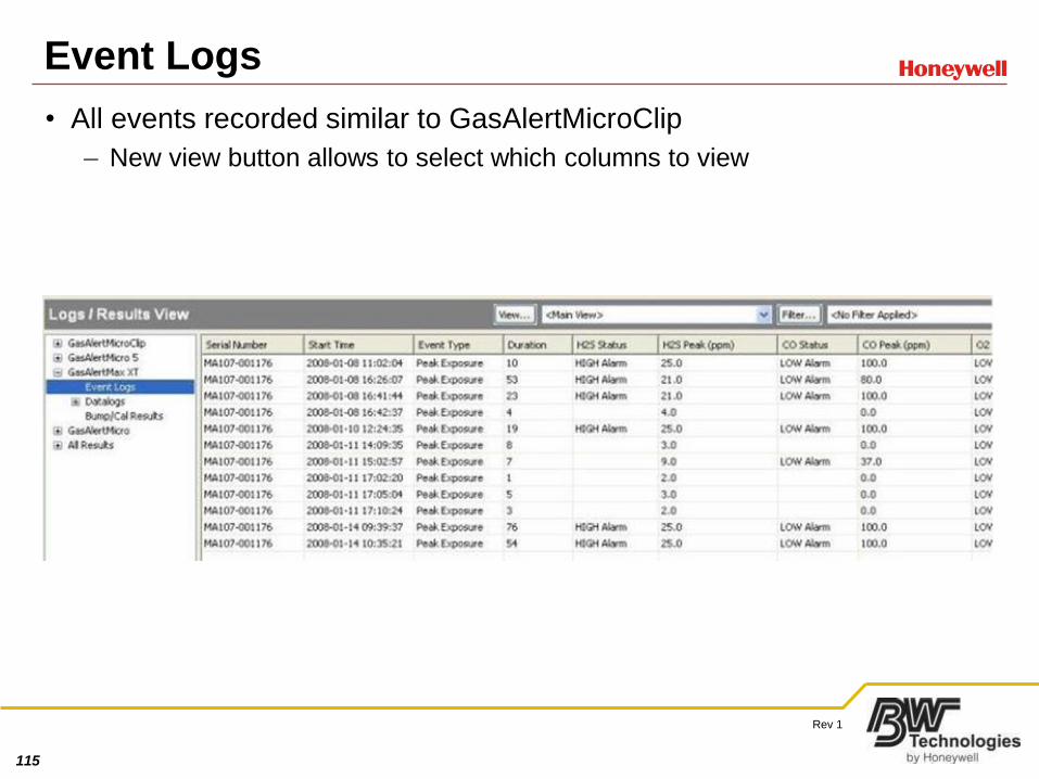
Event Logs
• All events recorded similar to GasAlertMicroClip
– New view button allows to select which columns to view
116
Rev 1
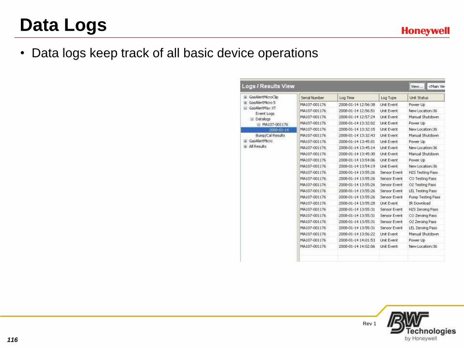
Data Logs
• Data logs keep track of all basic device operations
117
Rev 1
Service Advantages
• Battery is user/distributor serviceable
• Pump is user/distributor serviceable
• Rugged bass fittings and machine screws to prevent stripping
• Armored charger pins
• Inline pump filtration
118
Rev 1
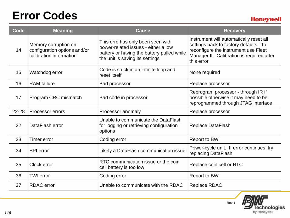
Error CodesCode Meaning Cause Recovery
14Memory corruption on configuration options and/or calibration information
This erro has only been seen with power-related issues - either a low battery or having the battery pulled while the unit is saving its settings
Instrument will automatically reset all settings back to factory defaults. To reconfigure the instrument use Fleet Manager II. Calibration is required after this error
15 Watchdog errorCode is stuck in an infinite loop and reset itself
None required
16 RAM failure Bad processor Replace processor
17 Program CRC mismatch Bad code in processorReprogram processor - through IR if possible otherwise it may need to be reprogrammed through JTAG interface
22-28 Processor errors Processor anomaly Replace processor
32 DataFlash errorUnable to communicate the DataFlashfor logging or retrieving configuration options
Replace DataFlash
33 Timer error Coding error Report to BW
34 SPI error Likely a DataFlash communication issuePower-cycle unit. If error continues, try replacing DataFlash
35 Clock errorRTC communication issue or the coin cell battery is too low
Replace coin cell or RTC
36 TWI error Coding error Report to BW
37 RDAC error Unable to communicate with the RDAC Replace RDAC
119
Rev 1
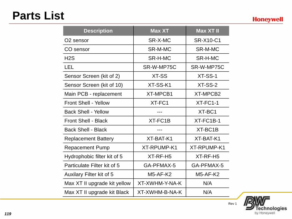
Parts ListDescription Max XT Max XT II
O2 sensor SR-X-MC SR-X10-C1
CO sensor SR-M-MC SR-M-MC
H2S SR-H-MC SR-H-MC
LEL SR-W-MP75C SR-W-MP75C
Sensor Screen (kit of 2) XT-SS XT-SS-1
Sensor Screen (kit of 10) XT-SS-K1 XT-SS-2
Main PCB - replacement XT-MPCB1 XT-MPCB2
Front Shell - Yellow XT-FC1 XT-FC1-1
Back Shell - Yellow --- XT-BC1
Front Shell - Black XT-FC1B XT-FC1B-1
Back Shell - Black --- XT-BC1B
Replacement Battery XT-BAT-K1 XT-BAT-K1
Repacement Pump XT-RPUMP-K1 XT-RPUMP-K1
Hydrophobic filter kit of 5 XT-RF-H5 XT-RF-H5
Particulate Filter kit of 5 GA-PFMAX-5 GA-PFMAX-5
Auxilary Filter kit of 5 M5-AF-K2 M5-AF-K2
Max XT II upgrade kit yellow XT-XWHM-Y-NA-K N/A
Max XT II upgrade kit Black XT-XWHM-B-NA-K N/A
120
Rev 1
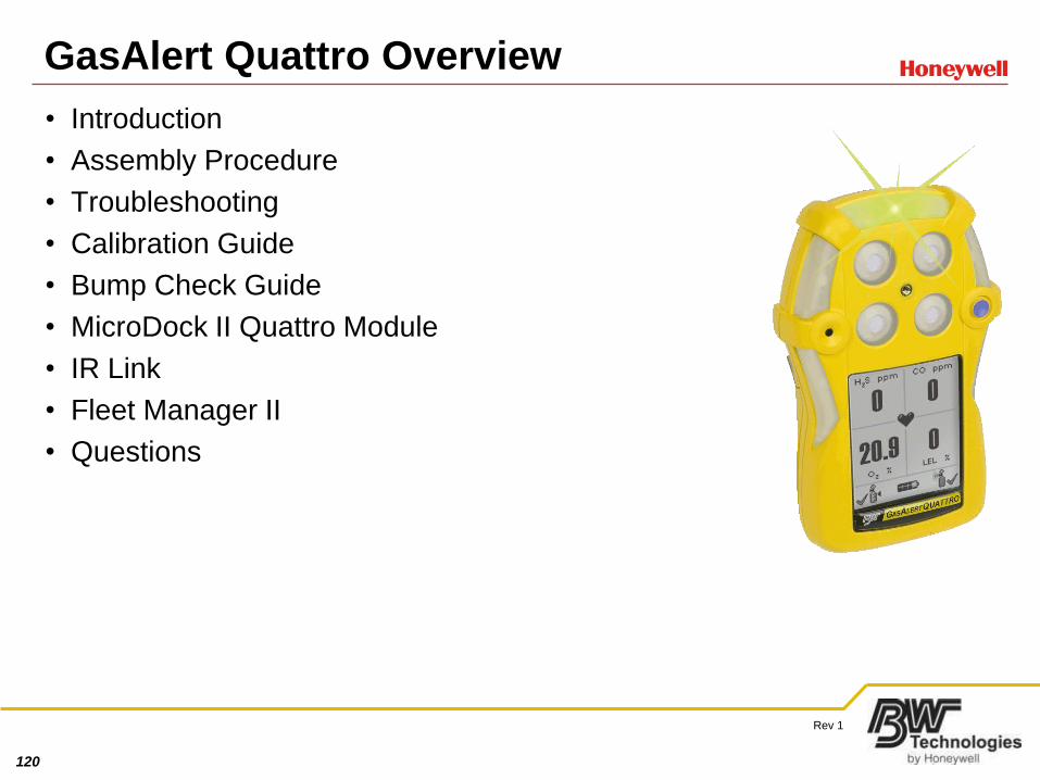
GasAlert Quattro Overview
• Introduction
• Assembly Procedure
• Troubleshooting
• Calibration Guide
• Bump Check Guide
• MicroDock II Quattro Module
• IR Link
• Fleet Manager II
• Questions
121
Rev 1
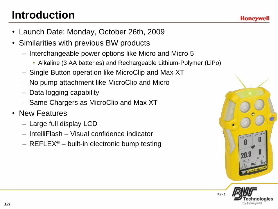
Introduction
• Launch Date: Monday, October 26th, 2009
• Similarities with previous BW products
– Interchangeable power options like Micro and Micro 5
• Alkaline (3 AA batteries) and Rechargeable Lithium-Polymer (LiPo)
– Single Button operation like MicroClip and Max XT
– No pump attachment like MicroClip and Micro
– Data logging capability
– Same Chargers as MicroClip and Max XT
• New Features
– Large full display LCD
– IntelliFlash – Visual confidence indicator
– REFLEX® – built-in electronic bump testing
122
Rev 1
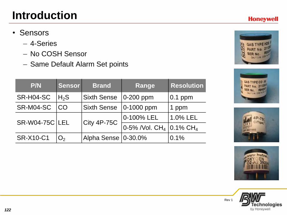
• Sensors
– 4-Series
– No COSH Sensor
– Same Default Alarm Set points
Introduction
P/N Sensor Brand Range Resolution
SR-H04-SC H2S Sixth Sense 0-200 ppm 0.1 ppm
SR-M04-SC CO Sixth Sense 0-1000 ppm 1 ppm
SR-W04-75C LEL City 4P-75C0-100% LEL 1.0% LEL
0-5% /Vol. CH4 0.1% CH4
SR-X10-C1 O2 Alpha Sense 0-30.0% 0.1%

123
Rev 1
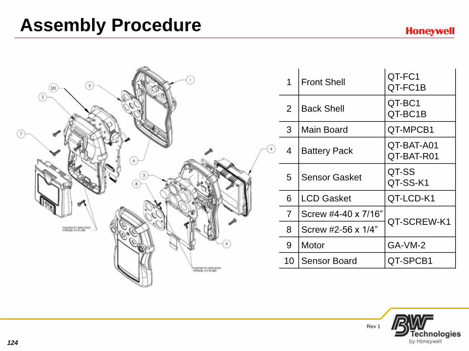
Assembly Procedure
• Standard unit includes
– Monitor
– Sensors
– Calibration adaptor and hose
– User manual
– Technical manual and Technical Documentation CD
– Power cord (rechargeable only)
– Alkaline tray with 3 AA Alkaline (alkaline only)
– Screwdriver for battery screw and routine maintenance
• Kits available
– Connectivity Kit (IR Link and Fleet Manager II 2.3)
– Confined Space Kit (Deluxe and Standard)
124
Rev 1
Assembly Procedure
101 Front Shell
QT-FC1
QT-FC1B
2 Back ShellQT-BC1
QT-BC1B
3 Main Board QT-MPCB1
4 Battery PackQT-BAT-A01
QT-BAT-R01
5 Sensor GasketQT-SS
QT-SS-K1
6 LCD Gasket QT-LCD-K1
7 Screw #4-40 x 7/16”QT-SCREW-K1
8 Screw #2-56 x 1/4”
9 Motor GA-VM-2
10 Sensor Board QT-SPCB1
125
Rev 1
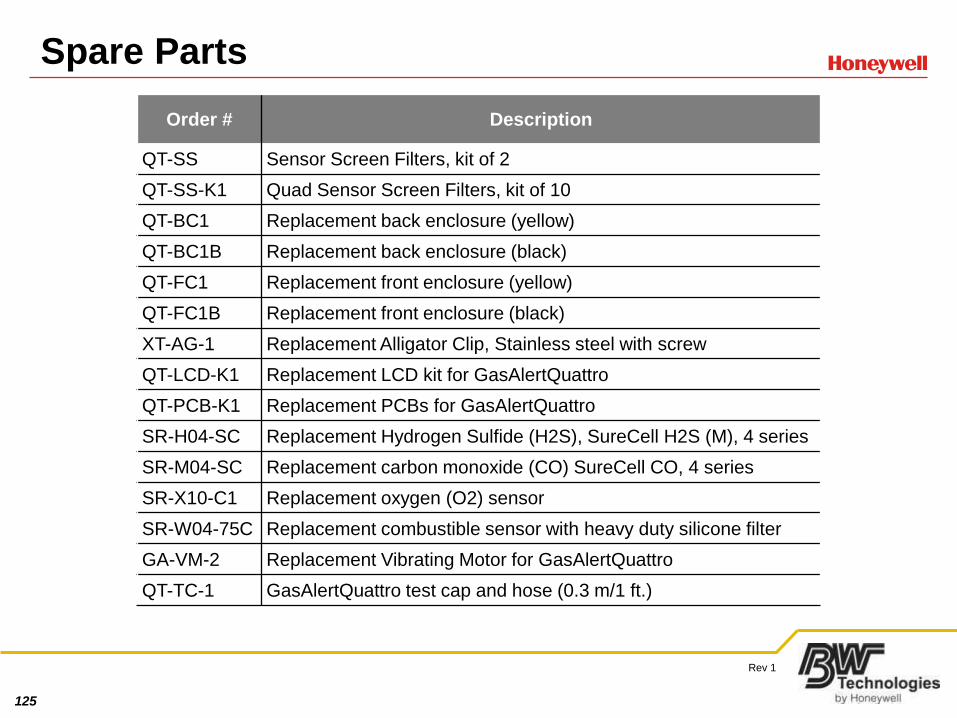
Spare Parts
Order # Description
QT-SS Sensor Screen Filters, kit of 2
QT-SS-K1 Quad Sensor Screen Filters, kit of 10
QT-BC1 Replacement back enclosure (yellow)
QT-BC1B Replacement back enclosure (black)
QT-FC1 Replacement front enclosure (yellow)
QT-FC1B Replacement front enclosure (black)
XT-AG-1 Replacement Alligator Clip, Stainless steel with screw
QT-LCD-K1 Replacement LCD kit for GasAlertQuattro
QT-PCB-K1 Replacement PCBs for GasAlertQuattro
SR-H04-SC Replacement Hydrogen Sulfide (H2S), SureCell H2S (M), 4 series
SR-M04-SC Replacement carbon monoxide (CO) SureCell CO, 4 series
SR-X10-C1 Replacement oxygen (O2) sensor
SR-W04-75C Replacement combustible sensor with heavy duty silicone filter
GA-VM-2 Replacement Vibrating Motor for GasAlertQuattro
QT-TC-1 GasAlertQuattro test cap and hose (0.3 m/1 ft.)
126
Rev 1
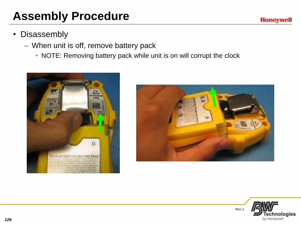
Assembly Procedure
• Disassembly
– When unit is off, remove battery pack
• NOTE: Removing battery pack while unit is on will corrupt the clock
127
Rev 1
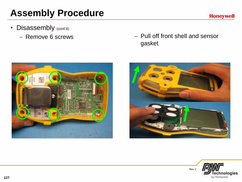
Assembly Procedure
• Disassembly (cont’d)
– Remove 6 screws – Pull off front shell and sensor
gasket

128
Rev 1
Assembly Procedure
• Disassembly (cont’d)
– Remove 2 smaller screws – Pull off back shell
129
Rev 1
Assembly Procedure
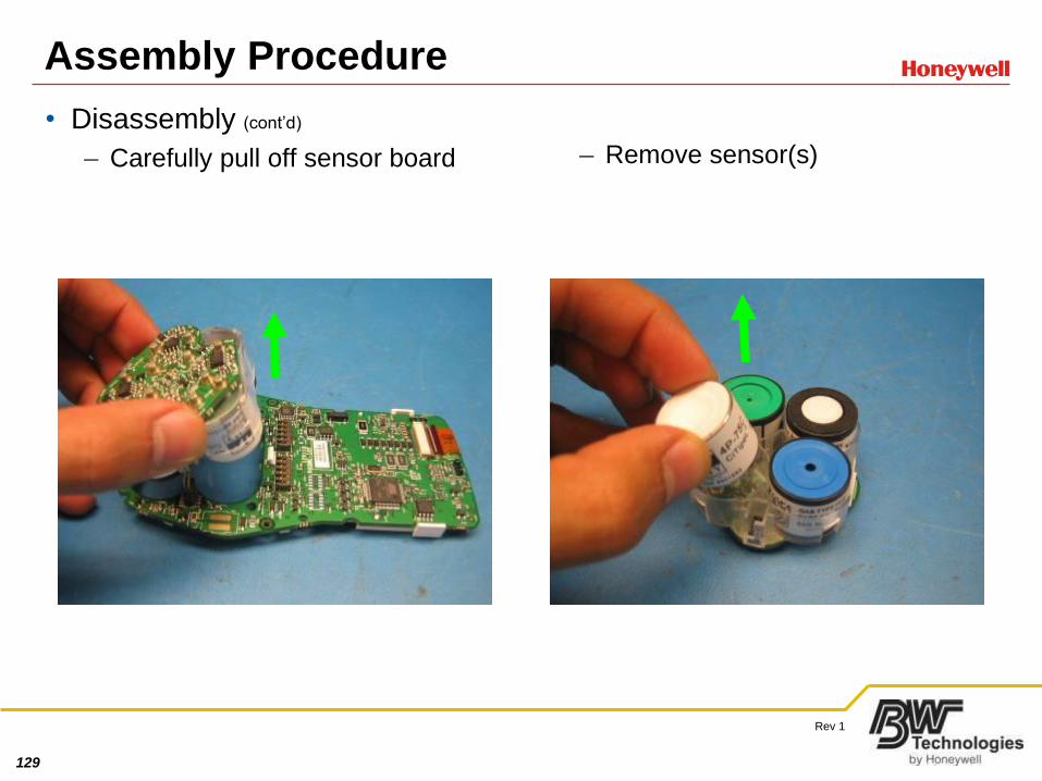
• Disassembly (cont’d)
– Carefully pull off sensor board – Remove sensor(s)
130
Rev 1
Assembly Procedure
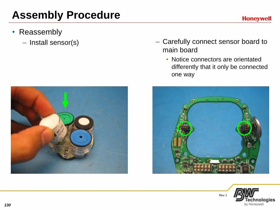
• Reassembly
– Install sensor(s) – Carefully connect sensor board to
main board
• Notice connectors are orientated
differently that it only be connected
one way
131
Rev 1
Assembly Procedure
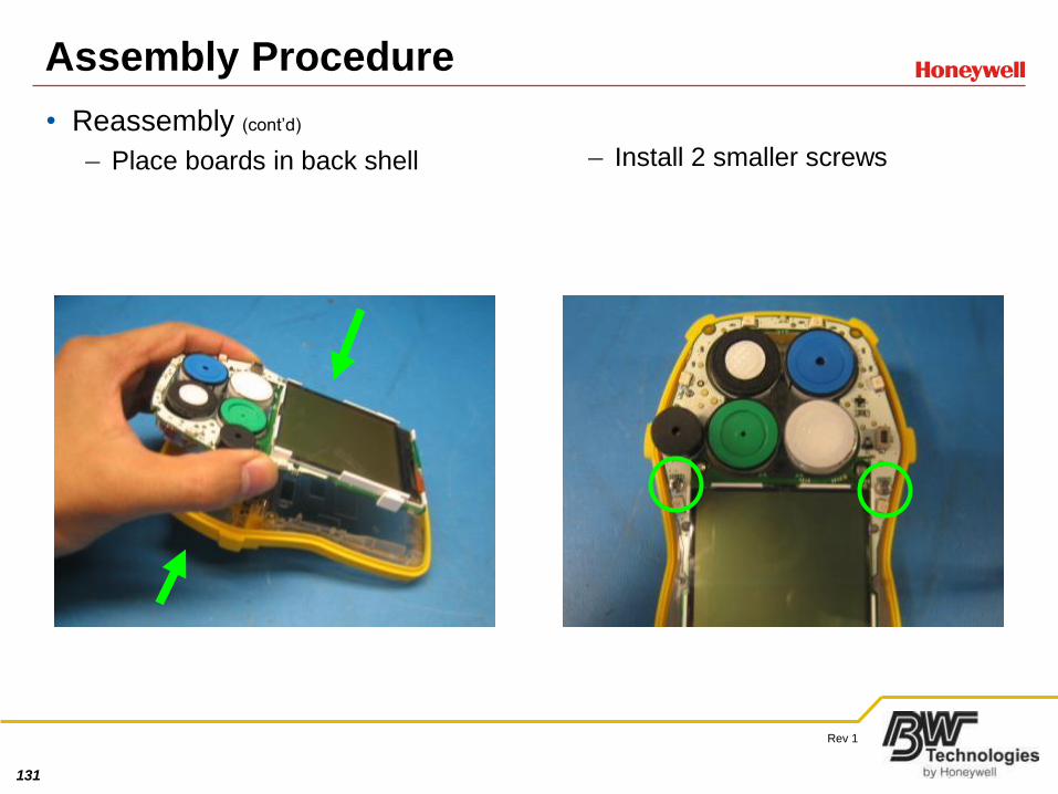
• Reassembly (cont’d)
– Place boards in back shell – Install 2 smaller screws
132
Rev 1
Assembly Procedure
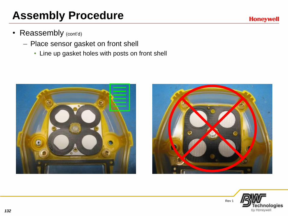
• Reassembly (cont’d)
– Place sensor gasket on front shell
• Line up gasket holes with posts on front shell
3
133
Rev 1
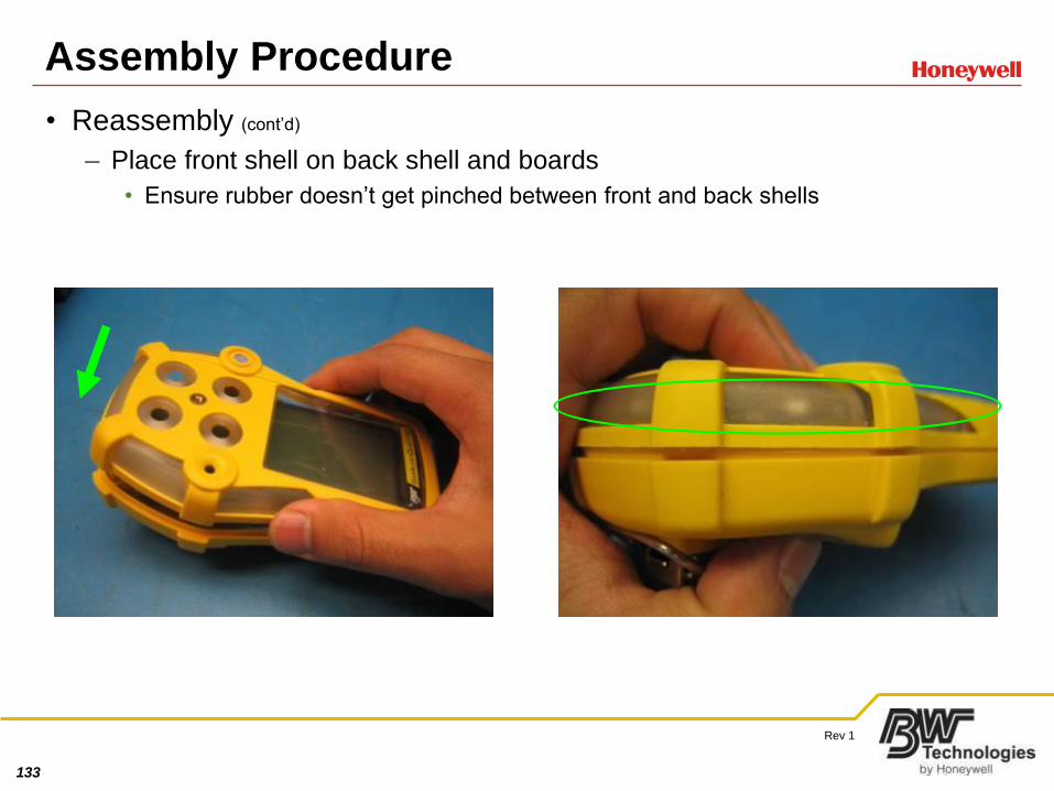
Assembly Procedure
• Reassembly (cont’d)
– Place front shell on back shell and boards
• Ensure rubber doesn’t get pinched between front and back shells
134
Rev 1
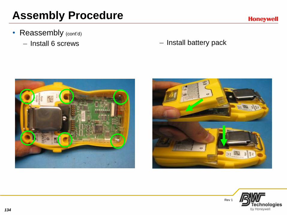
Assembly Procedure
• Reassembly (cont’d)
– Install 6 screws – Install battery pack
135
Rev 1
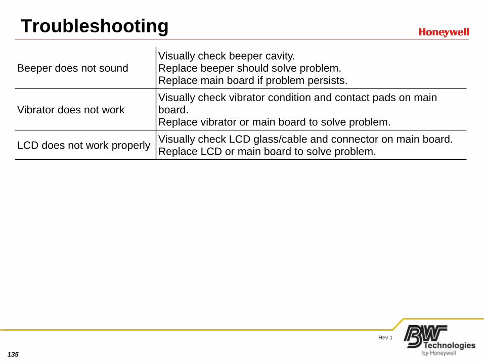
Troubleshooting
Beeper does not soundVisually check beeper cavity.Replace beeper should solve problem.Replace main board if problem persists.
Vibrator does not workVisually check vibrator condition and contact pads on main board.Replace vibrator or main board to solve problem.
LCD does not work properlyVisually check LCD glass/cable and connector on main board.Replace LCD or main board to solve problem.
136
Rev 1
Calibration Guide
• Manual Calibration
– Must use 4-Gas Mix with 18% O2 (like Max XT)
• Calibration span for O2 has limited range of 10.0% to 19.0%
• Mixes with 20.9% will not work
– Similar to MicroClip and Max XT
• Hold blue button for several seconds to get into Calibration Mode
• Let unit Auto-Zero
• Apply calibration gas through calibration adaptor and hose with 4-Gas Mix
137
Rev 1
Bump Check Guide
• O2 Breath Test
– Similar to other BW products
• Blow into sensor heads
• Ensure O2 reading drops and goes into Low Alarm
• Manual Bump Check
– Similar to other BW products
• Apply 4-Gas Mix to unit through calibration adaptor and hose
• Ensure all sensors go into Low Alarm

138
Rev 1
MicroDock II Quattro Module
• Physically similar to Micro 5 Module
• Functionality similar to MicroClip Module
– Bump Check
– Calibration
– Data Transfer
• Base station will store up to 10 (ten) 1MB Quattro
and/or Extreme Datalogs
• Can take up to 20 minutes depending on size of
datalog
– Charge
• Same method as MicroClip and Max XT –
MicroDock II is turned ON and Quattro unit is
turned OFF
• Able to charge LiPo Battery Packs independent of
Quattro unit
139
Rev 1
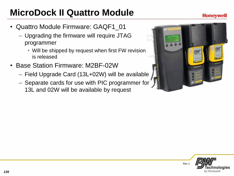
MicroDock II Quattro Module
• Quattro Module Firmware: GAQF1_01
– Upgrading the firmware will require JTAG
programmer
• Will be shipped by request when first FW revision
is released
• Base Station Firmware: M2BF-02W
– Field Upgrade Card (13L+02W) will be available
– Separate cards for use with PIC programmer for
13L and 02W will be available by request
140
Rev 1
IR Link
• Same Order Number (GA-USB1-IR)
• Works in Windows XP and later 32 bit systems
– If using Windows XP SP2 and older
• To maximize data transfer speed install Windows Hotfix
– WindowsXP-KB943198-v2-x86-ENU, available from
Microsoft website)
• Backwards compatible with MicroClip and Max XT
– Old IR Link does not work with Quattro
141
Rev 1
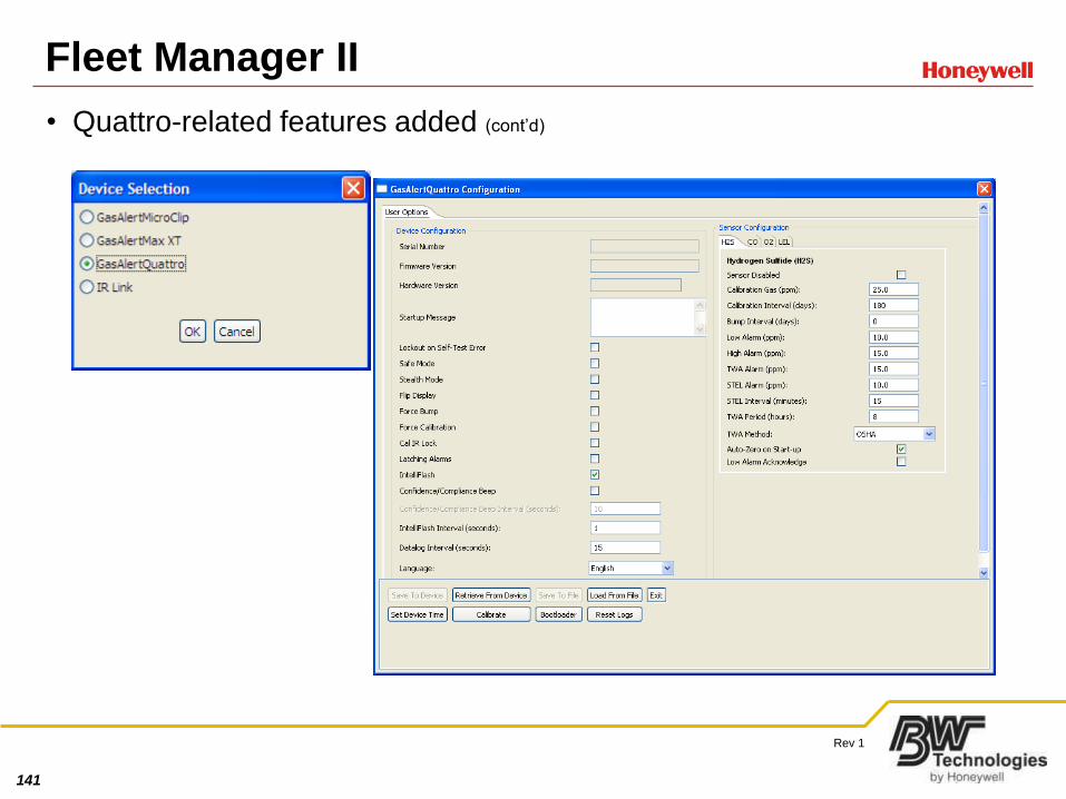
Fleet Manager II
• Quattro-related features added (cont’d)
142
Rev 1
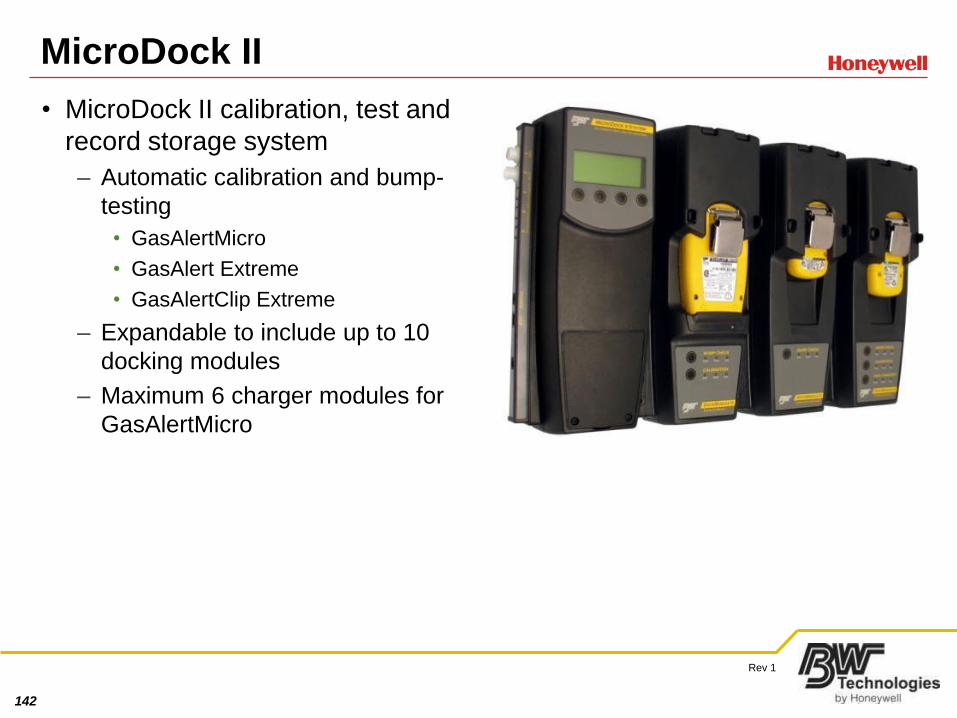
MicroDock II
• MicroDock II calibration, test and
record storage system
– Automatic calibration and bump-
testing
• GasAlertMicro
• GasAlert Extreme
• GasAlertClip Extreme
– Expandable to include up to 10
docking modules
– Maximum 6 charger modules for
GasAlertMicro
143
Rev 1
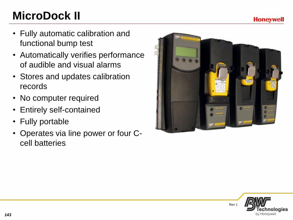
MicroDock II
• Fully automatic calibration and
functional bump test
• Automatically verifies performance
of audible and visual alarms
• Stores and updates calibration
records
• No computer required
• Entirely self-contained
• Fully portable
• Operates via line power or four C-
cell batteries
144
Rev 1
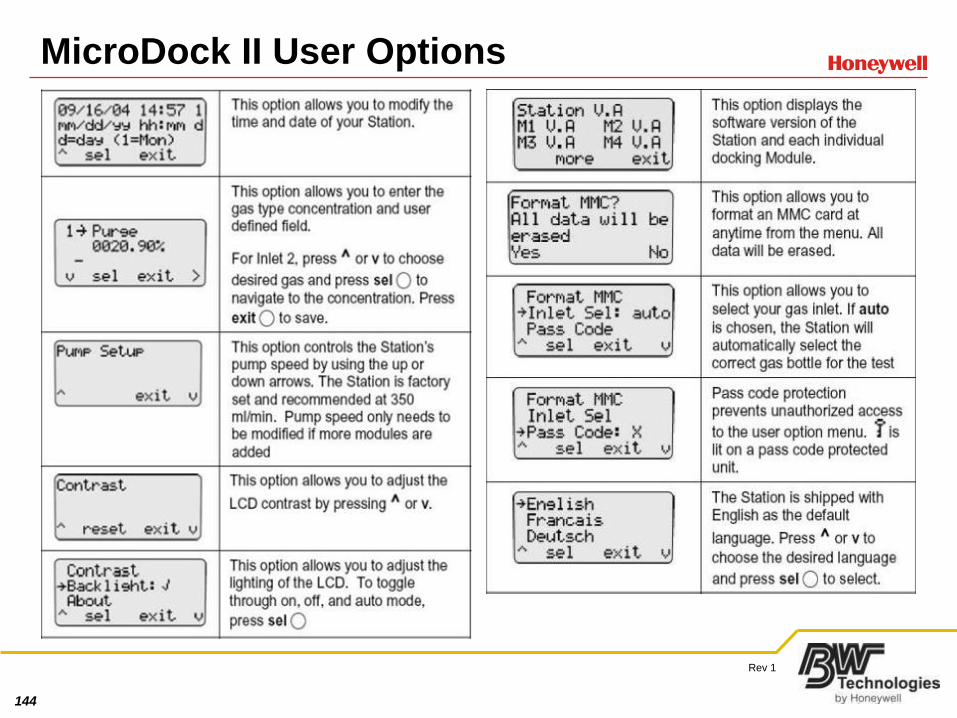
MicroDock II User Options
145
Rev 1
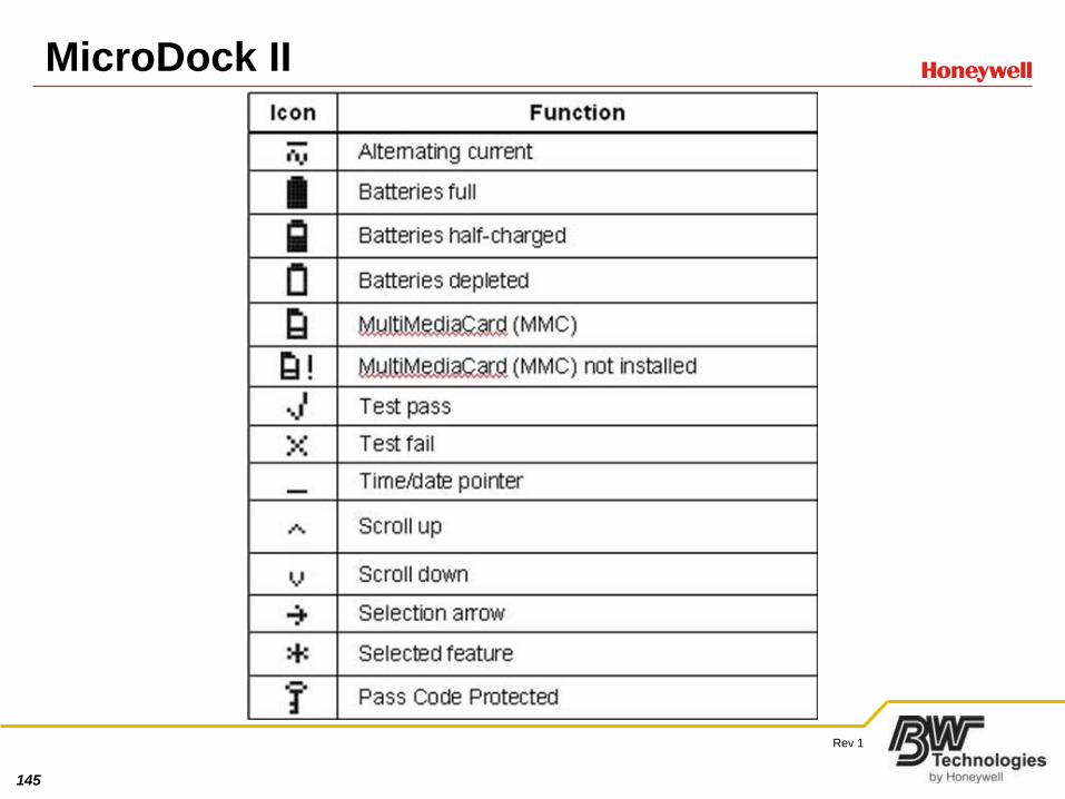
MicroDock II
146
Rev 1
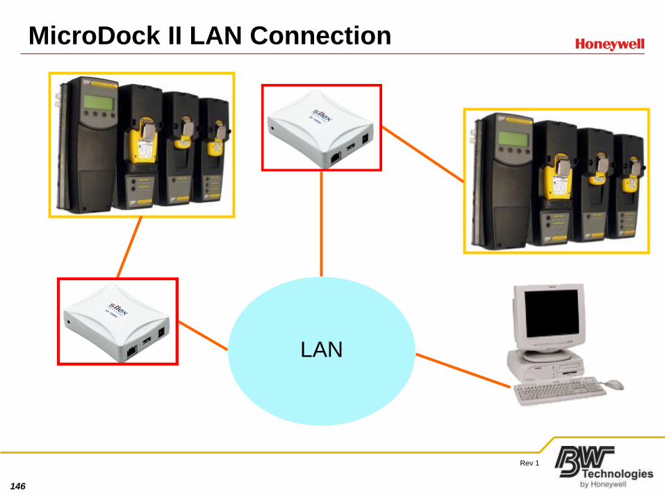
MicroDock II LAN Connection
LAN
147
Rev 1
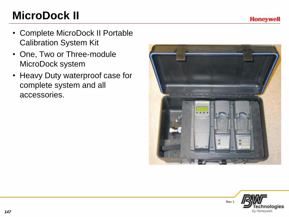
MicroDock II
• Complete MicroDock II Portable
Calibration System Kit
• One, Two or Three-module
MicroDock system
• Heavy Duty waterproof case for
complete system and all
accessories.
148
Rev 1
Card-based firmware Upgrades
• Enter user options
– Check firmware revision
• If 02H, or later upgrade using MMC upgrade card
• At this time current firmware revision is 02W
– Power down MicroDock II
– Open battery hatch on main module and remove MMC card
– Install 02W upgrade MMC card
– Power up MicroDock II
– Enter passcode 532 and allow upgrade to complete
149
Rev 1
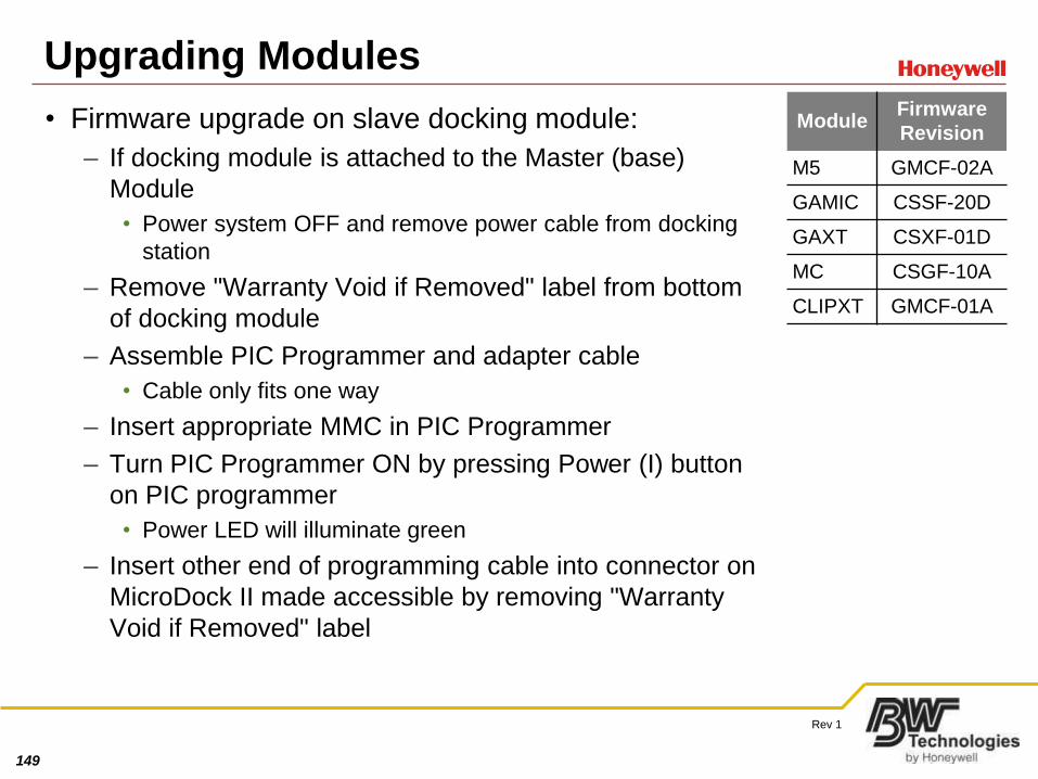
Upgrading Modules
• Firmware upgrade on slave docking module:
– If docking module is attached to the Master (base)
Module
• Power system OFF and remove power cable from docking
station
– Remove "Warranty Void if Removed" label from bottom
of docking module
– Assemble PIC Programmer and adapter cable
• Cable only fits one way
– Insert appropriate MMC in PIC Programmer
– Turn PIC Programmer ON by pressing Power (I) button
on PIC programmer
• Power LED will illuminate green
– Insert other end of programming cable into connector on
MicroDock II made accessible by removing "Warranty
Void if Removed" label
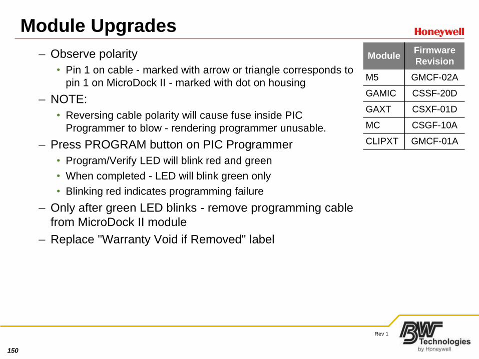
Module Firmware
Revision
M5 GMCF-02A
GAMIC CSSF-20D
GAXT CSXF-01D
MC CSGF-10A
CLIPXT GMCF-01A
150
Rev 1
Module Upgrades
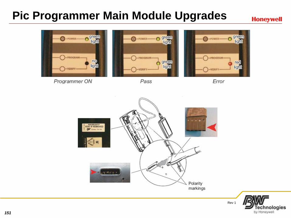
– Observe polarity
• Pin 1 on cable - marked with arrow or triangle corresponds to
pin 1 on MicroDock II - marked with dot on housing
– NOTE:
• Reversing cable polarity will cause fuse inside PIC
Programmer to blow - rendering programmer unusable.
– Press PROGRAM button on PIC Programmer
• Program/Verify LED will blink red and green
• When completed - LED will blink green only
• Blinking red indicates programming failure
– Only after green LED blinks - remove programming cable
from MicroDock II module
– Replace "Warranty Void if Removed" label
Module Firmware
Revision
M5 GMCF-02A
GAMIC CSSF-20D
GAXT CSXF-01D
MC CSGF-10A
CLIPXT GMCF-01A
151
Rev 1
Pic Programmer Main Module Upgrades
152
Rev 1
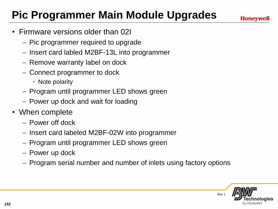
Pic Programmer Main Module Upgrades
• Firmware versions older than 02I
– Pic programmer required to upgrade
– Insert card labled M2BF-13L into programmer
– Remove warranty label on dock
– Connect programmer to dock
• Note polarity
– Program until programmer LED shows green
– Power up dock and wait for loading
• When complete
– Power off dock
– Insert card labeled M2BF-02W into programmer
– Program until programmer LED shows green
– Power up dock
– Program serial number and number of inlets using factory options
153
Rev 1
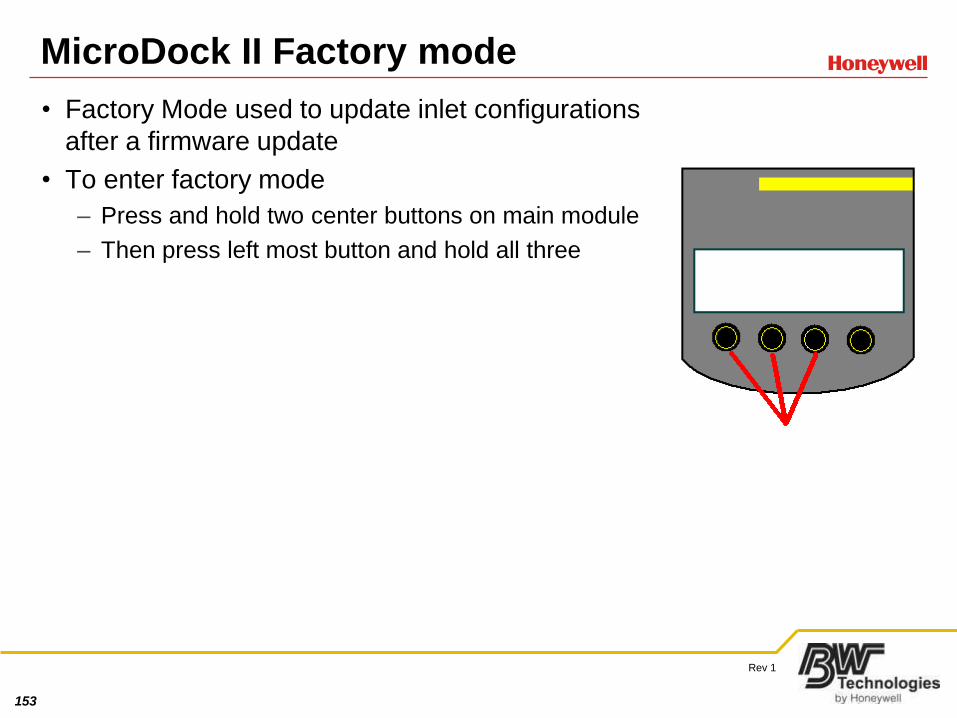
MicroDock II Factory mode
• Factory Mode used to update inlet configurations
after a firmware update
• To enter factory mode
– Press and hold two center buttons on main module
– Then press left most button and hold all three
154
Rev 1
Module Initialization
• Primary reason for module initialization is new module installation
– Initialization has been proven to be a fix for many docking station problems
• To initialize:
– Power down docking station
– Attach module
• Ensure both gas and electrical connections are made
– Press and hold bump check button on newly added module
• Then press and hold left most or power button on Main Module
– After a few seconds message “New receptacle added at position __” will
appear
– Closest module to main is 1 and so on
155
Rev 1
Re-Initialization
• If a dock is experiencing problems
– Check firmware revisions in user options for strange characters or missing
modules
• Inside firmware user options screen there should be one line for main module and
one for each dock module
• Initialization has one limitation, only distal module can be initialized
• If you are working on a dock with 5 instrument modules and the first
module is having problems you will have to remove the other 4 initialize
the first, attach the second initialize and so forth.
155
156
Rev 1
MD2 Limitations
• CL2 can be used for bump tests but cannot be used for calibration
• CLO2 and O3 cannot be tested using the docking station
• Only one instrument can be bumped or calibrated at a time
• The Fleetmanager2 options for BUMP on insertion and calibrated due
sensors are still in progress
156
157
Rev 1
Dock Troubleshooting guide
Problem Solution
All gasses are all failing on all monitors Ensure your cylinder is full, ensure you inlets are setup correctly
H2S is failing on all monitors Check the expiry date on your cylinder
The first bump performed always fails but each bump after that passed
The cylinder is connected to the purge
GAMICS are not being recognized by the MD2 Ensure they are DL2-IR units, or bend the metal switch further out of the module so that it is better
M5’s are not being recognized by the dock Ensure they are data logging units or ensure the M5 switch is working
MD2 will not talk to a PC Ensure the card indicator is visible on the screen, ensure the USB cable is no longer than 15 Feet, check the drive letter mapping on the PC, restart the PC
157
158
Rev 1
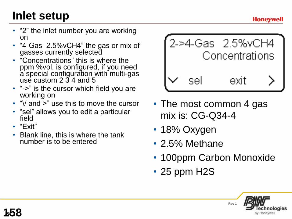
Inlet setup
• “2” the inlet number you are working on
• “4-Gas 2.5%vCH4” the gas or mix of gasses currently selected
• “Concentrations” this is where the ppm %vol. is configured, if you need a special configuration with multi-gas use custom 2 3 4 and 5
• “->” is the cursor which field you are working on
• “\/ and >” use this to move the cursor• “sel” allows you to edit a particular
field• “Exit”• Blank line, this is where the tank
number is to be entered
• The most common 4 gas
mix is: CG-Q34-4
• 18% Oxygen
• 2.5% Methane
• 100ppm Carbon Monoxide
• 25 ppm H2S
158
159
Rev 1
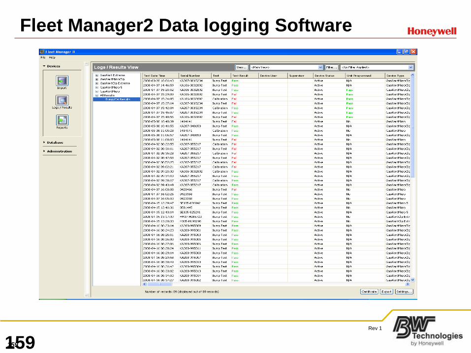
Fleet Manager2 Data logging Software
159
160
Rev 1
Fleet Manager 2
• FleetManager 2 is as simple as….
• Import records from the MicroDock2s connected
• Test a detector
• Browse the Bump and Calibration data for fails
• Generate a report of a failed bump test or calibration
• Generate Calibration Certificates
160
161
Rev 1
Fleet Manager 2 Hands on
• Import from a file
• Look at bump results
-Create a view
-Create a filter
-Create a calibration certificate
-Export to Excel
• Look at data logs
• Assign a user name
• Run a report
• Change device configuration
161
162
Rev 1
Questions
162