48
BROOKLYN WATERFRONT GREENWAY West Street Sustainable Stormwater Study Winter 2009 / 2010
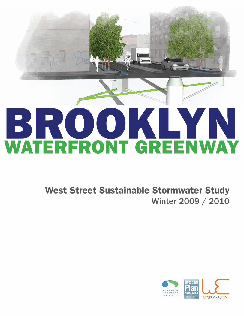
BROOKLYNWATERFRONT GREENWAY
West Street Sustainable Stormwater Study Winter 2009 / 2010


Credits
West Street Sustainable Stormwater Study report by Regional Plan Association and Brooklyn Greenway Initiative
Robert Freudenberg, Regional Plan AssociationRobert Pirani, Regional Plan AssociationMilton Puryear, Brooklyn Greenway Initiative Sarah Neilson, Regional Plan Association (former)
www.rpa.orgwww.brooklyngreenwayinitiative.org
In collaboration with:WE Design, LLC507 Clinton Avenue #1 Brooklyn, NY [email protected]
Project Principal: Tricia Martin
Contributions by:Tuzzolo Vajda Landscape ArchitectsMyles Throp, PEMatt Sisul
All designs, unless otherwise noted, prepared by WE Design, LLC.
This project was made possible through a generous grant provided by The New York Community Trust.
Winter 2009 / 2010
Acknowledgments
RPA, BGI and We Design would like to acknowledge and thank the following for their valuable contributions – as technical, policy and local resources – to this study. While we have greatly benefitted from the discussions and insights of these individuals, the report’s recommendations and any errors or omissions are our own.
Technical & Policy:Nick Barbaro, NYC Department of Environmental ProtectionNette Compton, NYC Department of Parks and RecreationJames Garin, NYC Department of Environmental ProtectionBram Gunther, NYC Department of Parks and RecreationDalila Hall, NYC Department of TransportationAaron Koch, Mayors Office of Long Term Planning and SustainabilityJohn McLaughlin, NYC Department of Environmental ProtectionWilla Ng, NYC Department of TransportationBryan Quinn, NYC Department of Parks and RecreationDavid Ramia, NYC Department of Environmental ProtectionAmir Rasty, NYC Department of TransportationCarter Strickland, NYC Department of Environmental ProtectionConstance Vivalis, NYC Department of Environmental Protection Jackson Wandres, RBATed Wright, NYC Department of Transportation
Local:Michael Heimbinder, Habitat MapChristine Holowacz, NAGJulie Lawrence, CB1Michael Freedman-Schnapp, NAGJeanine Rogers, Resident Lacey Tauber, NAGTeresa Toro, CB1Stephanie Thayer, Open Space AllianceJoseph Vance, Open Space Alliance Barbara Vetell, Greenpoint West Street Block Association Cara White, ResidentKate Zidar, Lower East Side Ecology Center
Brooklyn Greenway BackgroundIntroduction Project Statement Methodology
1. Overall Design Goals 1.0 Project Principles 1.1 Project Objectives
2. Project Assumptions 3. Context 3.1 City Context 3.2 Neighborhood Context 3.3 Existing Land-Use and Adopted Zoning 3.5 Watershed Map 3.6 West Street Conditions 3.7 Opportunities and Constraints 4. Phasing
5. Framework 5.1 Decentralized Systems 5.2 Treatment Trains
6. Design 6.1 Phase I - West Street - Primary Treatment 6.2 Phase I - West Street with Secondary Treatment 6.3 Phase II - Incremental Development 6.4 Phase III - Complete Stormwater Network
7. Next Steps and Recommendations
8. Maintenance: Operation and Costs
9. References
10. Appendix 11.1 Engineering Report 11.2 Stormwater Techniques and Methods Precedents 11.3 Plant Lists
Table of Contents
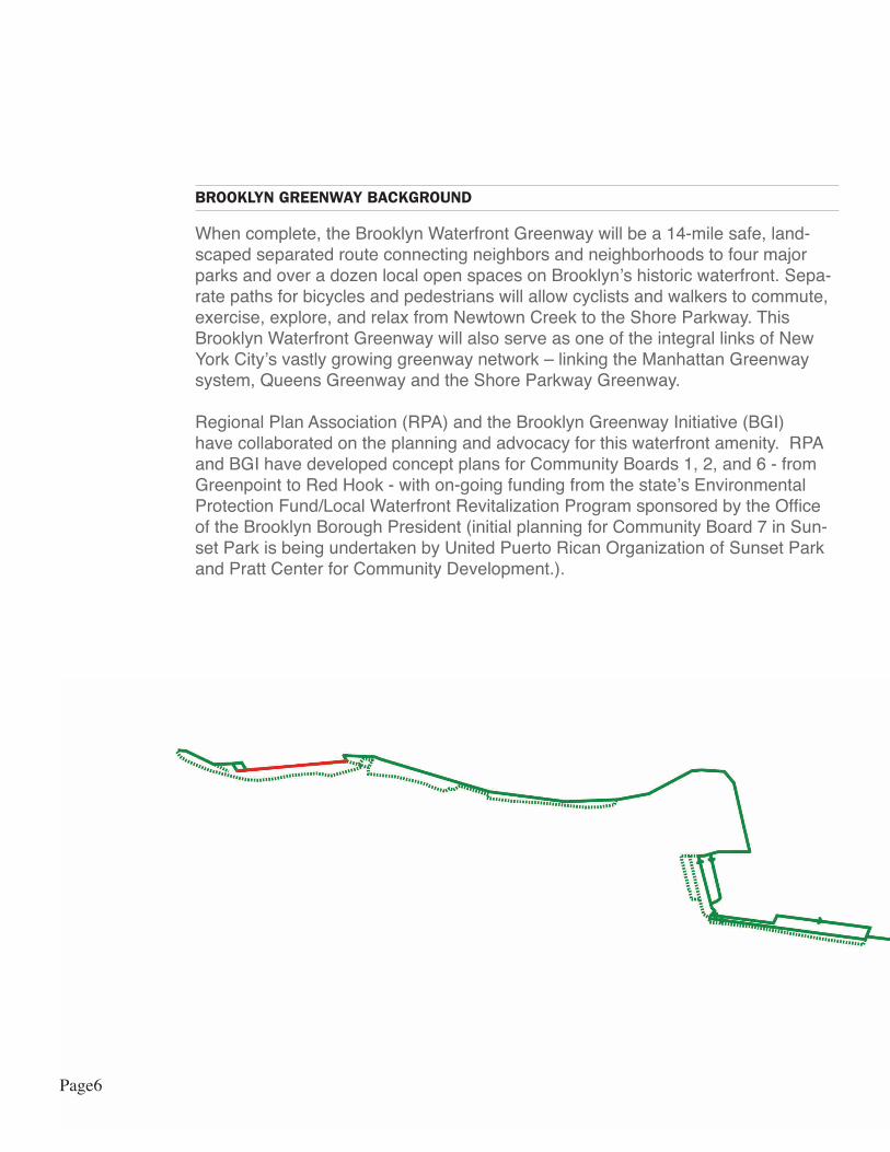
BROOKLYN GREENWAY BACKGROUND
When complete, the Brooklyn Waterfront Greenway will be a 14-mile safe, land-scaped separated route connecting neighbors and neighborhoods to four major parks and over a dozen local open spaces on Brooklyn’s historic waterfront. Sepa-rate paths for bicycles and pedestrians will allow cyclists and walkers to commute, exercise, explore, and relax from Newtown Creek to the Shore Parkway. This Brooklyn Waterfront Greenway will also serve as one of the integral links of New York City’s vastly growing greenway network – linking the Manhattan Greenway system, Queens Greenway and the Shore Parkway Greenway.
Regional Plan Association (RPA) and the Brooklyn Greenway Initiative (BGI) have collaborated on the planning and advocacy for this waterfront amenity. RPA and BGI have developed concept plans for Community Boards 1, 2, and 6 - from Greenpoint to Red Hook - with on-going funding from the state’s Environmental Protection Fund/Local Waterfront Revitalization Program sponsored by the Office of the Brooklyn Borough President (initial planning for Community Board 7 in Sun-set Park is being undertaken by United Puerto Rican Organization of Sunset Park and Pratt Center for Community Development.).
Page6
BROOKLYN GREENWAY BACKGROUND
These plans, based on community workshops in 2004 and 2007, set out goals, identify the specific route and partners, and outline key steps toward implementa-tion. Design Guidelines and a Stewardship Plan provide a framework for the next phase of development and identify management options for the completed route.
Construction of the Brooklyn Waterfront Greenway will be funded using federal, state and city capital funds. To date, BGI has secured over $20 million in federal funding thanks to the efforts of Congresswoman Nydia Velazquez and the NYC DOT..
More than 70% of the Greenway is on public rights of way. NYC DOT is now work-ing on advancing Brooklyn Waterfront Greenway to help move the project from con-ceptual planning to design and construction by creating a Master Plan and prepar-ing preliminary designs for specific sections of the Greenway, including West Street and around the Brooklyn Navy Yard.
Through the community workshops conducted by Brooklyn Greenway Initiative and Regional Plan Association, the Greenpoint/Williamsburg community chose West Street as the Greenway route and supported the elimination of parking on the street and its conversion to a one-way road, to allow for the construction of the Greenway. This decision was formalized by CB1’s April 2008 resolution supporting these ac-tions. While a final determination on the Greenway route and the future of West Street will be made as part of the NYC DOT Master Plan process, CB 1’s resolution is the basis for our assumptions for this study.
Page7
IntroductionPROJECT STATEMENT
One of the goals for the Brooklyn Waterfront Greenway is to establish a healthygreen edge to Brooklyn, including the integration of sustainable stormwatermanagement. A successful stormwater management plan includes methods for detention and cleansing, as well as methods for controlling the movement of wa-ter from one location to another. Although relatively narrow, landscaping along the Greenway can be designed to address stormwater generated within its borders. The Greenway also threads along and through a variety of neighborhoods and land uses, providing an effective means for moving water and an opportunity to detain and cleanse water within the adjacent properties.
West Street is the northern-most stretch of the Greenway and is the focus of this stormwater management study. The opportunity exists to integrate soft infrastruc-ture including trees, shrubs, herbaceous plants, and soil within the public right of way that will provide critical stormwater infrastructure, reduce (and perhaps pre-vent) combined sewer overflows, regulate city temperatures, clean the air and provide a beautiful streetscape for local and future residents and bikers moving throughout Greenpoint.
METHODOLOGY
To carry out the West Street Sustainable Stormwater Study, WE Design, RPA and BGI worked over a number of phases. Phase I included an analysis of the existing conditions of West Street to understand how different stormwater techniques could be applied. During this Phase, the team developed and consulted with a Technical and Policy Advisory Committee comprised of relevant City agencies including NYC Department of Transportation, NYC Department of Environmental Protection and the Mayor’s Office of Long Term Planning and sustainability. Further, a thorough precedent study of a variety of techniques was explored and measured against the constraints presented by the site, city regulations, and the desired program by the community (see Appendix 10.2).
Phase II involved developing preliminary designs, based on feedback from the Technical Advisory Committee. These designs were presented to the community at a full Community Board 1 meeting and shared via the internet for public comment.
The final phase of this project considered stewardship responsibilities for these designs and the final output of the entire project is presented in this report.
While this study is intended to be conceptual, the policy, technical, and community work groups help to ensure that the ideas we explored were consistent with city-wide sustainable goals, technically feasible and as much as possible consistent with current agency standards, and had widespread community support.
Page8
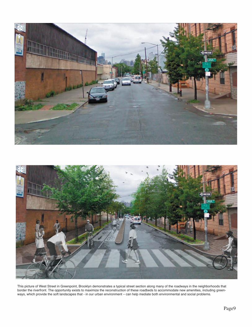
This picture of West Street in Greenpoint, Brooklyn demonstrates a typical street section along many of the roadways in the neighborhoods that border the riverfront. The opportunity exists to maximize the reconstruction of these roadbeds to accommodate new amenities, including green-ways, which provide the soft landscapes that - in our urban environment – can help mediate both environmental and social problems.
Page9

Planning Principles
The guiding principles of the project include the following:
Create site-specific source stormwater controls along West Street that can be repli-cated in similar contexts along other stretches of the Greenway.
Connect the stormwater system along West Street to the Side Streets and Street Ends that lead to the river and maximize all waterfront open spaces to receive, retain and treat rainwater.
Explore the potential of public and private collaborations to connect stormwater systems along the public right of way with adjacent private development parcels.
Celebrate the ongoing momentum of PlaNYC and other initiatives such as the Stormwater Management Plan and Best Management Practices Task Force, Park’s High Performance Landscape Guidelines, and Million Trees NYC.
1.0 Planning Principles
Page10
DESIGNING A GREEN, SOFT STORMWATER MANAGEMENT SYSTEM
The project is guided by the following design objectives:
Green in order to contribute to city-wide efforts to increase the number of trees and biomass within the five boroughs and to beautify the streets.
Flexible in design and construction to increase its replicability along the entire Greenway and the city at large.
Simple in construction and maintenance to reduce costs and to increase it’s use in a diversity of applications along NYC’s streets.
Engineered to handle projected volumes of water along West Street and to at least meet minimum criteria set by the city for preventing Combined Sewer Overflows (See Appendix 10.1 for a full engineering report).
Connected so that as much as possible the stormwater is prevented from en-tering the city piped system.
Design Objectives1.1
Page11
ASSUMPTIONS
The study area includes all of the Public Right of Way along West Street including the sidewalks, streets, and intersections.
The storm event that is being analyzed has 1.7” of precipitation.(Criteria used by NYCDPR / Greenstreets).
This precipitation is at an intensity of 1=5.95 inches / hr. with a time to concentra-tion of tc = 6 minutes. This is the 5-year storm as defined by the DEP.
That a capture of .5” - 1” of rainwater will prevent 80% of all CSO events, and that these smaller volume events have the greatest concentration of “first flush” stormwater pollutants (source: Sustainable Stormwater Management Plan: 2008: A Greener, Greater New York).
Since survey data is unavailable it is assumed that the average grades from East to West and from North to South are +/- 1%.
The water table is approximately 5’ below the existing ground plane (confirmed from spokesperson from Palin Development - Parcel 9).
Planters must maintain a 10’ horizontal setback from edge of sewer main pipes.
The West Street reconfiguration will include a one-way southbound traffic lane and a two-way bike lane.
Eventually the Greenway will extend north from Eagle Street and connect to Du-pont allowing a continuous bikeway connection to the Newtown Creek waterfront.
Assumptions2.0
Page12
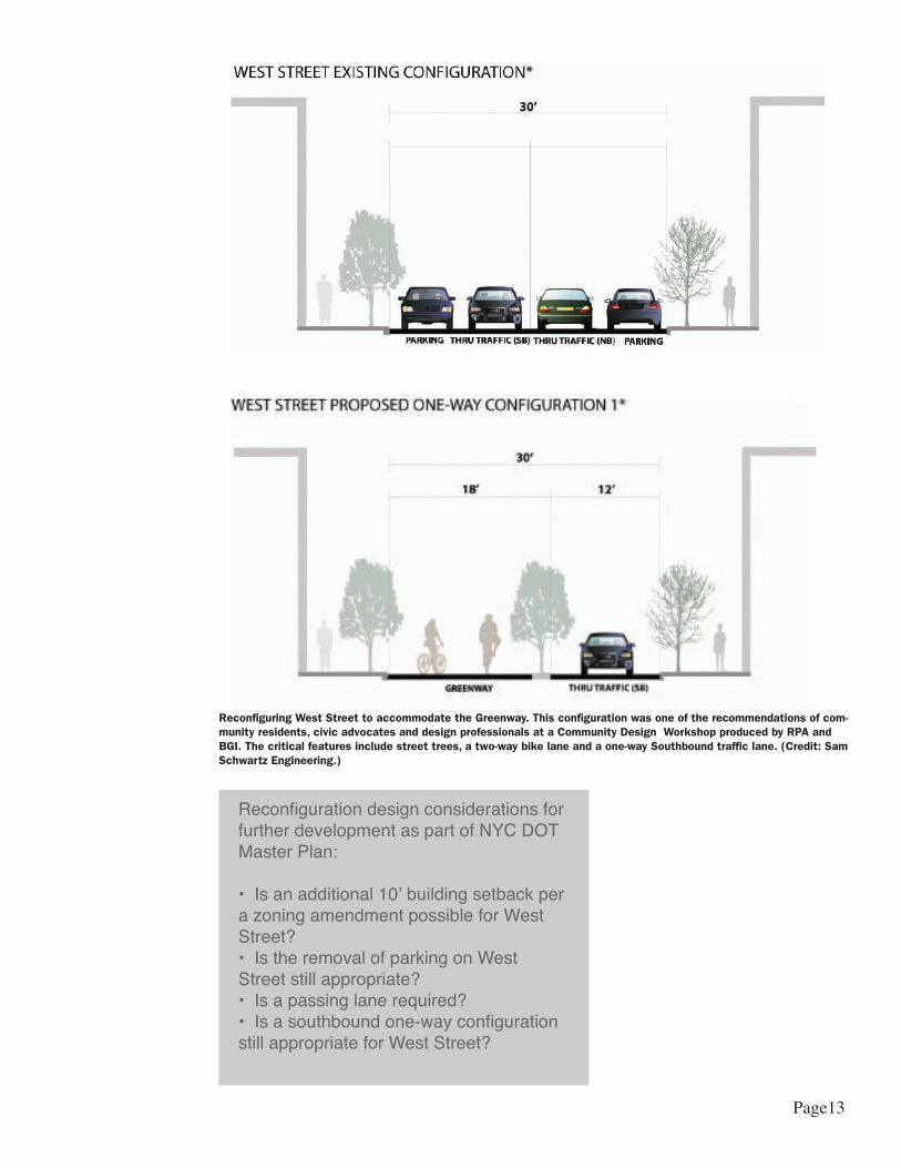
Reconfiguration design considerations for further development as part of NYC DOT Master Plan:
• Is an additional 10’ building setback per a zoning amendment possible for West Street? • Is the removal of parking on West Street still appropriate?• Is a passing lane required?• Is a southbound one-way configuration still appropriate for West Street?
Reconfiguring West Street to accommodate the Greenway. This configuration was one of the recommendations of com-munity residents, civic advocates and design professionals at a Community Design Workshop produced by RPA and BGI. The critical features include street trees, a two-way bike lane and a one-way Southbound traffic lane. (Credit: Sam Schwartz Engineering.)
Page13

CITY CONTEXT
West Street is located in Greenpoint, Brooklyn in the Northernmost neighborhood in Brooklyn with Newtown Creek to the North, the East River to the West, Williams-burg to the South and Bushwich to the West. The West Street Sustainable Storm-water Study is one of a number of other projects throughout the five boroughs that are exploring pilot project opportunities for meeting the sustainable goals outlined in PlaNYC.
For example, just North of Greenpoint in Queens, EDC is working on a sustain-able development that includes infrastructure, buildings and waterfront parks for the Hunters Point South Sites. Other projects throughout the city include Brooklyn Bridge Park, The South Bronx Greenway, Gowanus Sponge Park and an expan-sion of the Bluebelt in Staten Island. Each of these projects is fleshing out many of the important questions and issues that are necessary for applying green prin-ciples in a dense and highly developed city like New York.
It is critical that the information gleaned from these projects is shared and dis-cussed with many stakeholders to ensure that the big visions set are implemented in a timely, efficient manner.
Context3.1
A map of New York City, including the five boroughs and New Jersey. The red marker designates Greenpoint, Brooklyn
Queens
NewJersey
StatenIsland
Brooklyn
Bronx
Manhattan
Page14
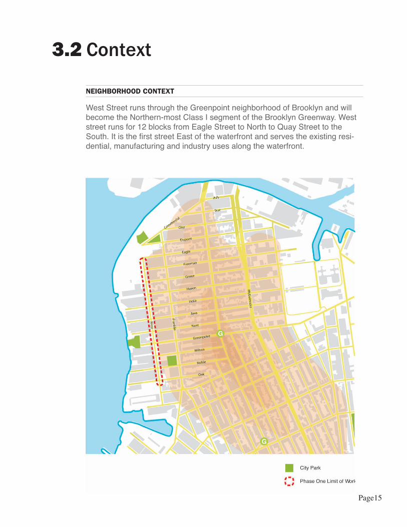
NEIGHBORHOOD CONTEXT
West Street runs through the Greenpoint neighborhood of Brooklyn and will become the Northern-most Class I segment of the Brooklyn Greenway. West street runs for 12 blocks from Eagle Street to North to Quay Street to the South. It is the first street East of the waterfront and serves the existing resi-dential, manufacturing and industry uses along the waterfront.
Context3.2
Page15

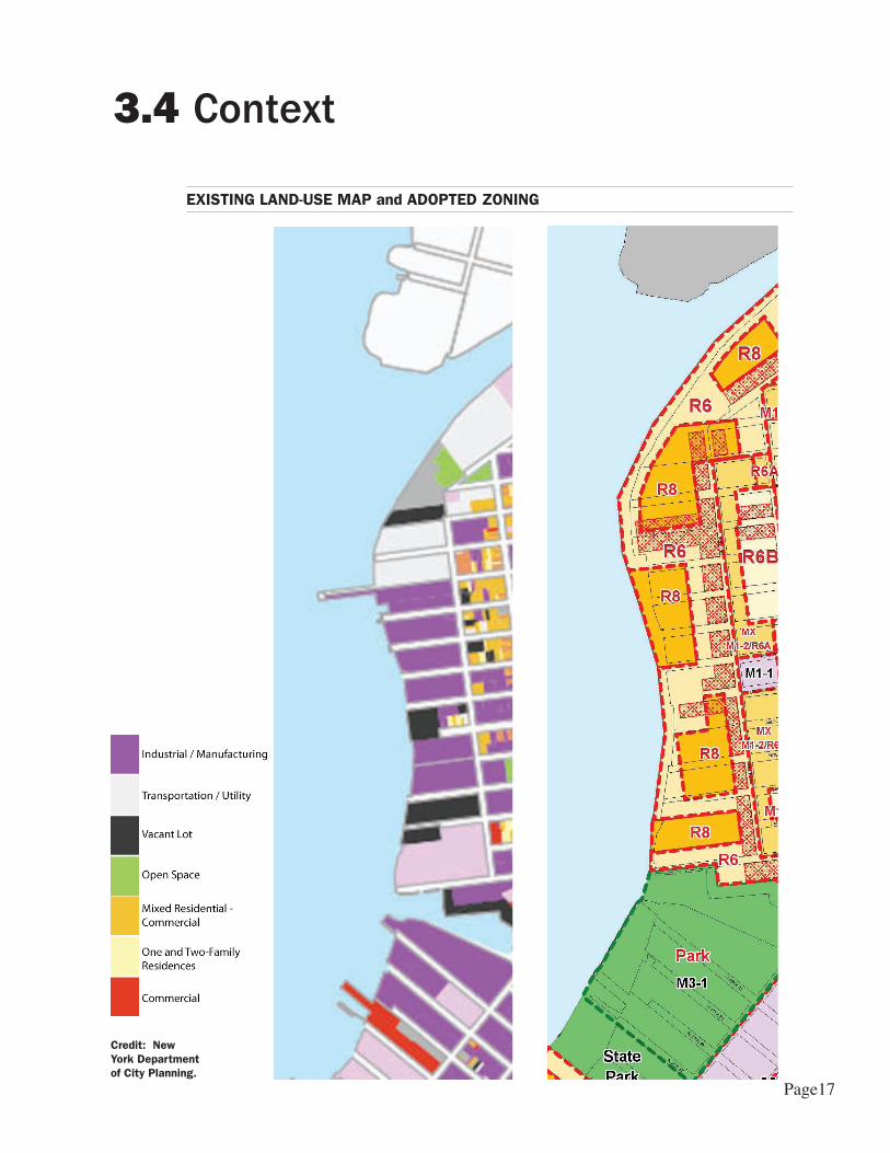
EXISTING LAND-USE
The existing land uses reflect historical zoning and industry. The blocksadjacent to the waterfront were zoned for Heavy Industrial uses (M3). Just upland of the M3 zone is M1 Light Industrial characterized largely by warehouses. This zone forms a buffer between heavy industrial and the eastern residential neighbor-hoods.
The lots adjacent to West Street are dominated by large parking areas, full block warehouse buildings, and vacant lots and buildings. A temporary Transmitter Park opened this past Summer and the permanent park is slated to be complete in 2010. It serves as the only public park along the East River inGreenpoint. Another park, Barge Park, is North of West Street along NewtownCreek. It is currently used for active recreation and is paved in asphalt.
An existing bikeway runs along Franklin Street, one block east of West Street. Due to street and land use constraints, a class 1 Greenway that includes sepa-rated pedestrian and vehicular conveyance as well as the potential for substantial plantings, would not be suitable.
Context3.3
ADOPTED ZONING
In 2005 the Greenpoint – and neighboring Williamsburg - waterfront was rezoned to replace industry and manufacturing with Mixed-Use Residential, Residential and Commercial land uses. Over time the new zoning will change the character and physical qualities of the Greenpoint waterfront neighborhood with tall buildings replacing short-story warehouses, new shorelines replacing damaged bulkheads, waterfront parks replacing abandoned lots, and an increase of tens of thousands of residents. A new public esplanade will run north to south along the East River. Given the substantial numbers of pedestrians anticipated on the 12’ esplanade path, it will not fulfill the greenway design objectives of a dedicated path for cyclists that is physically separated from traffic.
Page16
Context3.4
EXISTING LAND-USE MAP and ADOPTED ZONING
Credit: New York Department of City Planning.
Page17

Context3.5
WATERSHED MAP
West Street is located one block from the East River and is the streetat the lowest elevations of the watershed. If water could flow uninterrupted bydrains, it would flow towards West Street and Commercial Street, making itsway to the East River and Newtown Creek. Although West Street is close tothe waterfront, its entire length is above the 100-year floodplain and does not appear to have significant flooding problems. There are 6 Combined Sewer Outfalls within the watershed boundary and 3 additional ones just outside.
Page18
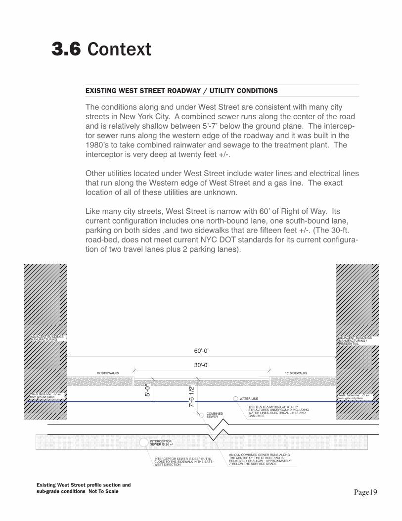
EXISTING WEST STREET ROADWAY / UTILITY CONDITIONS
The conditions along and under West Street are consistent with many city streets in New York City. A combined sewer runs along the center of the road and is relatively shallow between 5’-7’ below the ground plane. The intercep-tor sewer runs along the western edge of the roadway and it was built in the 1980’s to take combined rainwater and sewage to the treatment plant. The interceptor is very deep at twenty feet +/-.
Other utilities located under West Street include water lines and electrical lines that run along the Western edge of West Street and a gas line. The exact location of all of these utilities are unknown.
Like many city streets, West Street is narrow with 60’ of Right of Way. Its current configuration includes one north-bound lane, one south-bound lane, parking on both sides ,and two sidewalks that are fifteen feet +/-. (The 30-ft. road-bed, does not meet current NYC DOT standards for its current configura-tion of two travel lanes plus 2 parking lanes).
Context3.6
Existing West Street profile section and sub-grade conditions Not To Scale
INTERCEPTOR SEWER IS 20 +/-
Water table line: -5' +/- from ground plane
Water table line: -5' +/- from ground plane
COMBINED SEWER
30'-0"
WATER LINE
INTERCEPTOR SEWER IS DEEP BUT IS CLOSE TO THE SIDEWALK IN THE EAST - WEST DIRECTION
AN OLD COMBINED SEWER RUNS ALONG THE CENTER OF THE STREET AND IS RELATIVELY SHALLOW - APPROXIMATELY 7' BELOW THE SURFACE GRADE
60'-0"
THERE ARE A MYRIAD OF UTILITY STRUCTURES UNDERGOUND INCLUDING WATER LINES, ELECTRICAL LINES AND GAS LINES
5'-0
"
15' SIDEWALKS 15' SIDEWALKS
ADJACENT BUILDINGSMANUFACTURING
ADJACENT BUILDINGSMANUFACTURING / RESIDENTIAL
7'-6 1
/2"
Page19
OPPORTUNITIES
The creation of the Brooklyn Waterfront Greenway along West Street presents an incredible opportunity to design and build a pilot project that uses sustainable stormwater management. The following are other opportunities that the site pres-ents:
1. Few, if any, remnants within the street right of way that need to be preserved or protected (for example, there are only a handful of trees currentlyalong the street);2. West Street is not within the 100’ floodplain, thus reducing the risks forflooding;3. There are no (or very few) driveways along West Street providing more opportu-nity for continuous elements along the edges of the streets;4. One-block from the river - possibilities of strong connections between WestStreet and the East River;5. Zoning Change: the entire site west of the West Street will be transformedinto medium-high rise residential / commercial structures. Such wide-swepttransformations are opportunities for subsequent changes and improvements; and6. Opportunities for connecting West Street improvements with adjacent parks and open spaces associated with private development.
Opportunities and Constraints3.7
CONSTRAINTS
As with any infrastructural project in New York City there are a myriad of site and policy driven constraints, including:
1. Narrow street right of way for accommodating multiple amenities2. Underground sea of utilities and existing infrastructure with different agency ownership and jurisdiction3. Relatively high water table - 5’ +/-4. Possible site contamination due to historical and current manufacturing / indus-trial uses5. Uncertain timetable for new developments 6. Shallow combined sewer pipe running along the center of the street-bed7. Difficult to adhere to DEP standard of 10’ setback from sewer pipes
Page20
PHASING4.0
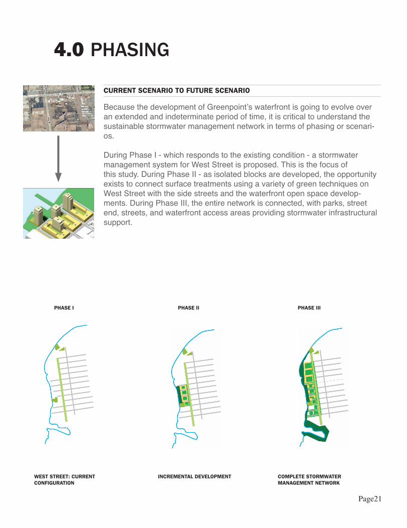
CURRENT SCENARIO TO FUTURE SCENARIO
Because the development of Greenpoint’s waterfront is going to evolve overan extended and indeterminate period of time, it is critical to understand thesustainable stormwater management network in terms of phasing or scenari-os.
During Phase I - which responds to the existing condition - a stormwatermanagement system for West Street is proposed. This is the focus ofthis study. During Phase II - as isolated blocks are developed, the opportunityexists to connect surface treatments using a variety of green techniques on West Street with the side streets and the waterfront open space develop-ments. During Phase III, the entire network is connected, with parks, street end, streets, and waterfront access areas providing stormwater infrastructural support.
WEST STREET: CURRENTCONFIGURATION
INCREMENTAL DEVELOPMENT COMPLETE STORMWATER MANAGEMENT NETWORK
PHASE I PHASE II PHASE III
Page21
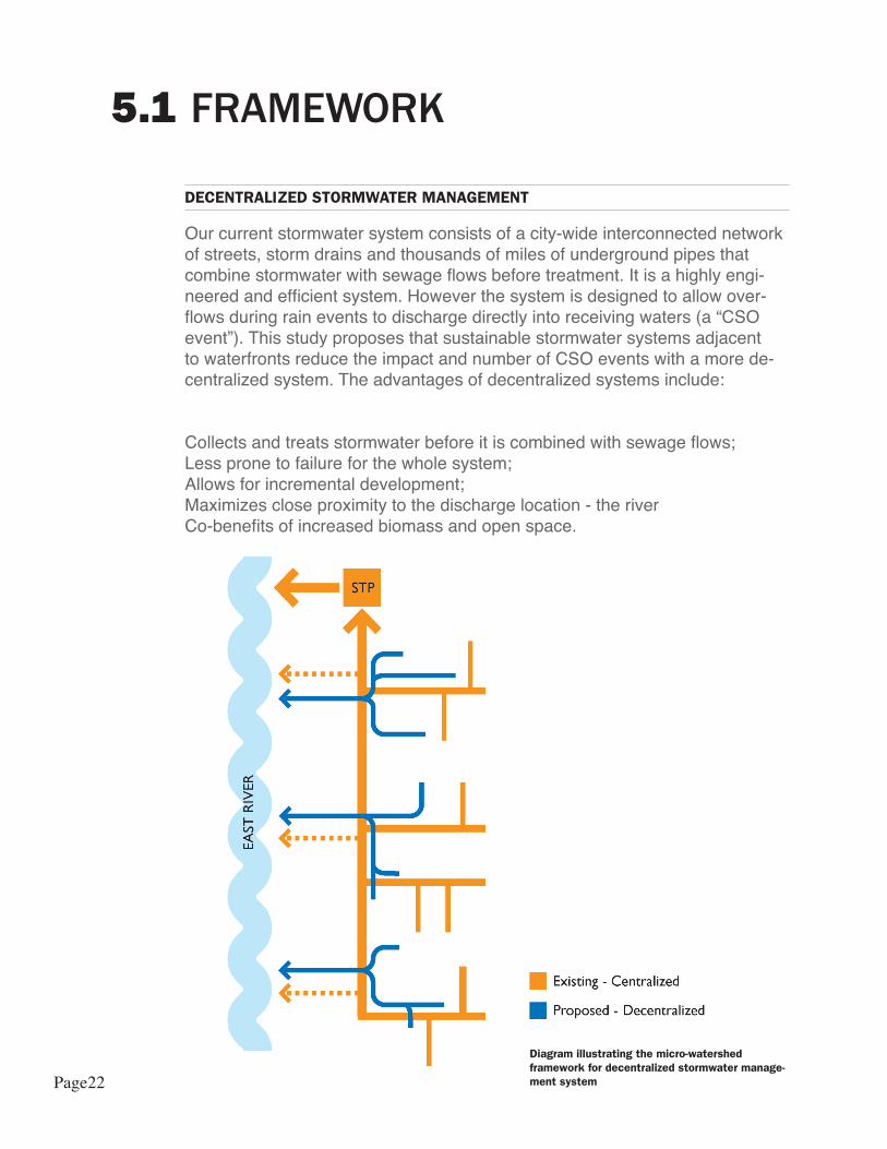
DECENTRALIZED STORMWATER MANAGEMENT
Our current stormwater system consists of a city-wide interconnected networkof streets, storm drains and thousands of miles of underground pipes that combine stormwater with sewage flows before treatment. It is a highly engi-neered and efficient system. However the system is designed to allow over-flows during rain events to discharge directly into receiving waters (a “CSO event”). This study proposes that sustainable stormwater systems adjacentto waterfronts reduce the impact and number of CSO events with a more de-centralized system. The advantages of decentralized systems include:
Collects and treats stormwater before it is combined with sewage flows;Less prone to failure for the whole system;Allows for incremental development;Maximizes close proximity to the discharge location - the riverCo-benefits of increased biomass and open space.
FRAMEWORK5.1
Diagram illustrating the micro-watershed framework for decentralized stormwater manage-ment system Page22
FRAMEWORK5.2
TREATMENT TRAINS
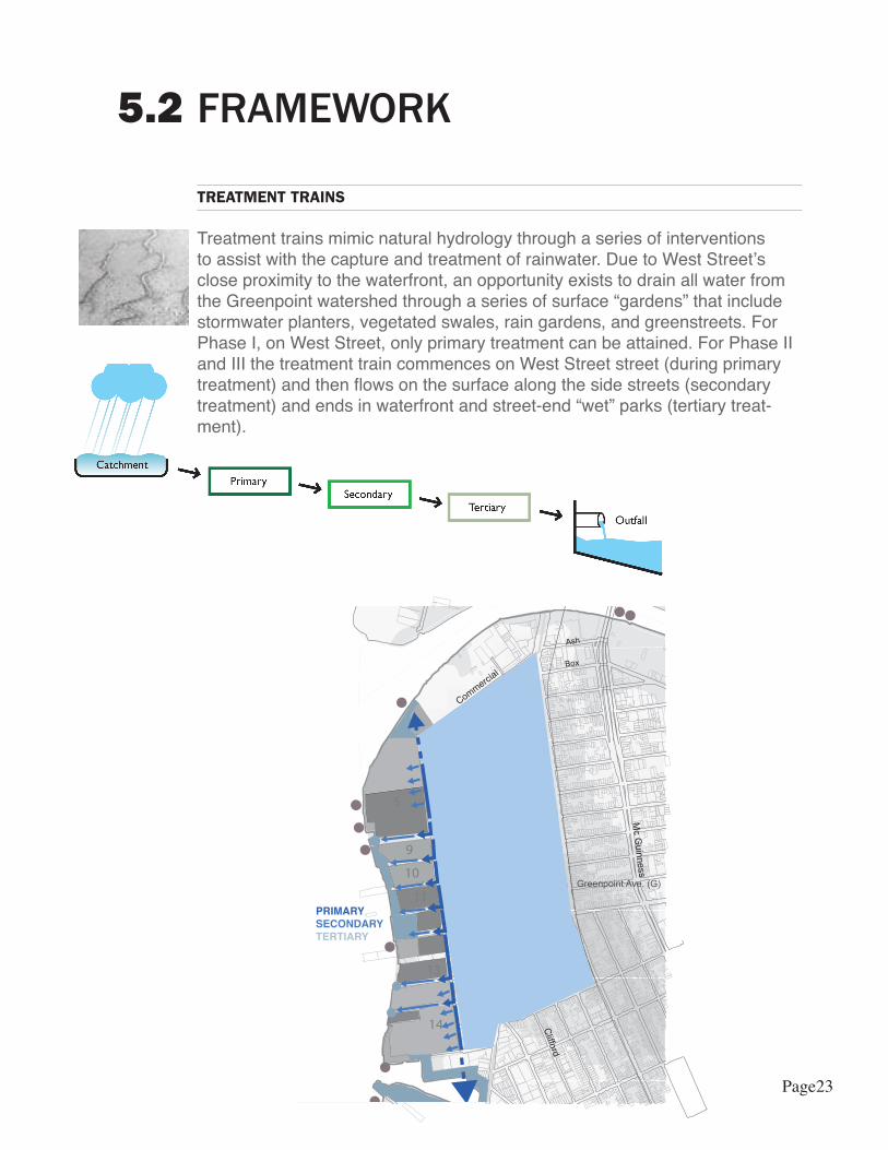
Treatment trains mimic natural hydrology through a series of interventions to assist with the capture and treatment of rainwater. Due to West Street’s close proximity to the waterfront, an opportunity exists to drain all water from the Greenpoint watershed through a series of surface “gardens” that include stormwater planters, vegetated swales, rain gardens, and greenstreets. For Phase I, on West Street, only primary treatment can be attained. For Phase II and III the treatment train commences on West Street street (during primary treatment) and then flows on the surface along the side streets (secondary treatment) and ends in waterfront and street-end “wet” parks (tertiary treat-ment).
!
Green
India
Eagle
Dupont
Freeman
Java
Kent
Milton
Greenpoint
Noble
Oak
Clifford
Box
Ash
HuronFranklin
West
Comm
ercial
Clay
Calyer
McGuinness
Greenpoint Ave. (G)
14
13
11
10
9
5
PRIMARYSECONDARYTERTIARY
Page23
DESIGN - PHASE 1 - WEST STREET 6.1
PHASE ONE - PRIMARY TREATMENT
The focus of Phase I is the stormwater design for West Street. Stormwater planters are proposed as the primary treatment allowing an opportunity for source controls that include trees and plantings within a narrow street bed. The stormwater planters will run along the west and east sides of West Street from Eagle Street to Quay Street. Each block stretch will be treated as an isolated “watershed” with additional treatment options as water flows through secondary and tertiary treatment systems (see 6.2 and 6.3).
The proposed design for West Street is a response to the site conditions – constraints and opportunities – and measured against the design objectives listed in 1.1 Design Objectives: The solution had to be green, flexible in de-sign, simple in construction and for maintenance, and engineered to meet the minimum criteria for preventing a CSO event during a 95% storm event. The stormwater method that best met these objects were stormwater planters installed on both the east and west sides of West Street.
The planters run along the length of each city block and include one landing break between each planter. The planters are five feet wide – a minimum dimension to ensure the healthy growth of trees, shrubs, grasses and perenni-als – thus meeting the green criteria for the stormwater design.
The following drawings include dimensions for the planters that support the size of the site area and to accommodate the specific site water volumes; however, the benefits of stormwater planters are their flexibility and replicabil-ity for many sites. They can be designed to be different sizes and shapes and can vary in depth depending on budget, water table depths, bedrock depths, and water volumes to capture and treat.
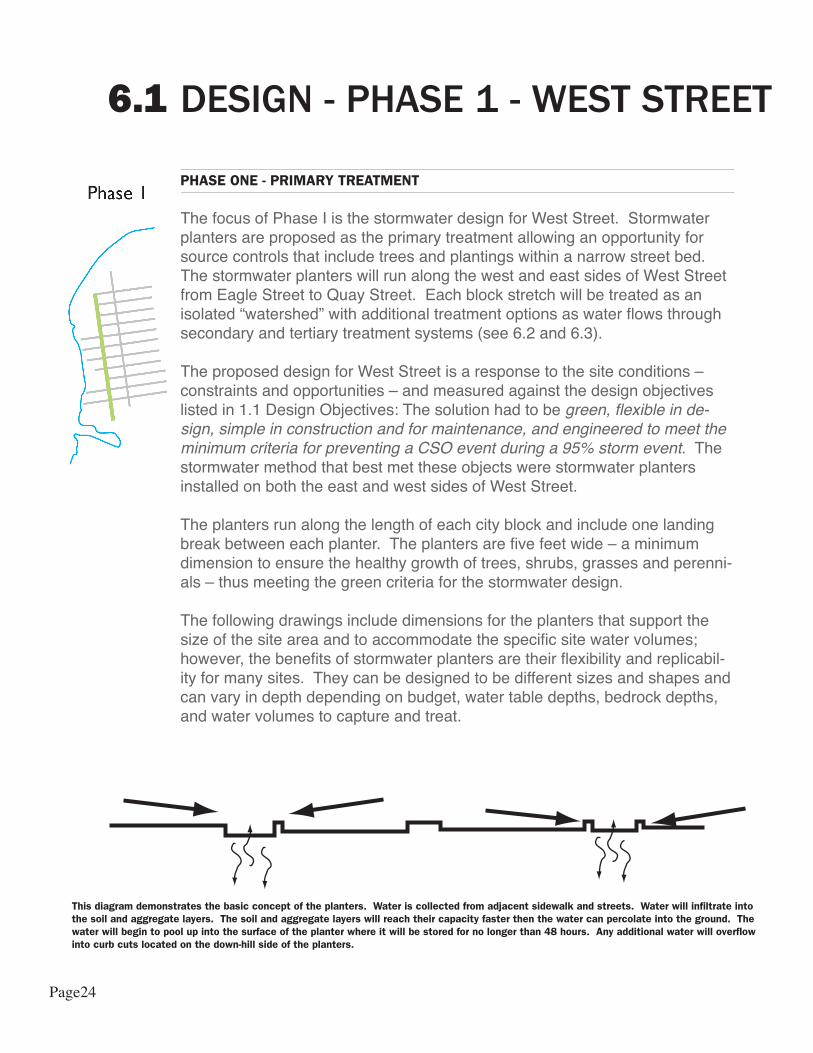
This diagram demonstrates the basic concept of the planters. Water is collected from adjacent sidewalk and streets. Water will infiltrate into the soil and aggregate layers. The soil and aggregate layers will reach their capacity faster then the water can percolate into the ground. The water will begin to pool up into the surface of the planter where it will be stored for no longer than 48 hours. Any additional water will overflow into curb cuts located on the down-hill side of the planters.
Page24
PHASE ONE - PRIMARY TREATMENT
The other benefit to using stormwater planters is that they are easy to construct and maintain. Using primarily soft materials, the planters are constructed with a layer of aggregate, soil, mulch and plants. Curbs are the only hard elements required and their depth will depend on specific site requirements. Some planters will also require check dams and sediment traps to reduce clogging and to easily remove salt and other sediments that enter the planters.
The planters along West Street will retain the first 1” of runoff from the design area, preventing 80% of CSO events from occurring. Moreover, this first inch of storm-water carries with it the “first flush” of concentrated pollutants from the streets and sidewalks making its retention even more valuable for water quality protection.
Dupont
Eagle
Clay
Box
Ash
Commercial
Freeman
Green
Huron
India
Java
McG
uin
ness
West
Franklin Kent
Greenpoint
Milton
Noble
Oak
City Park
100 Year Flood Plain
Phase One Limit of Work
Combined Sewer Overlow
Dupont
Eagle
Clay
Box
Ash
Commercial
Freeman
Green
Huron
India
Java
McG
uin
ness
Franklin Kent
Greenpoint
Milton
Noble
Oak
Phase One Limit of WorkWatershed
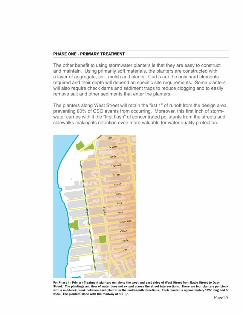
For Phase I - Primary Treatment planters run along the west and east sides of West Street from Eagle Street to Quay Street. The plantings and flow of water does not extend across the street intersections. There are four planters per block with a mid-block break between each planter in the north-south directions. Each planter is approximately 125’ long and 5’ wide. The planters slope with the roadway at 1% +/-
Page25

Design considerations and items for further development as part of the NYC DOT Master Plan:
• Design will need to consider any exist-ing driveways that enter on West Street• Although curb median is mountable for fire truck and emergency access, final di-mensions of the one-way traffic lane and two-way bikeway will need to be reviewed• The current configuration of south-bound traffic adjacent to north-bound bike traffic lane presents a conflict and will need to be reviewed in final design• Although the sidewalk widths meet code and zoning regulations, their narrow configuration should be reviewed in final design- Salt loving plants should be used to miti-gate plant damage due to salt application during winter months
Not to Scale
Page26
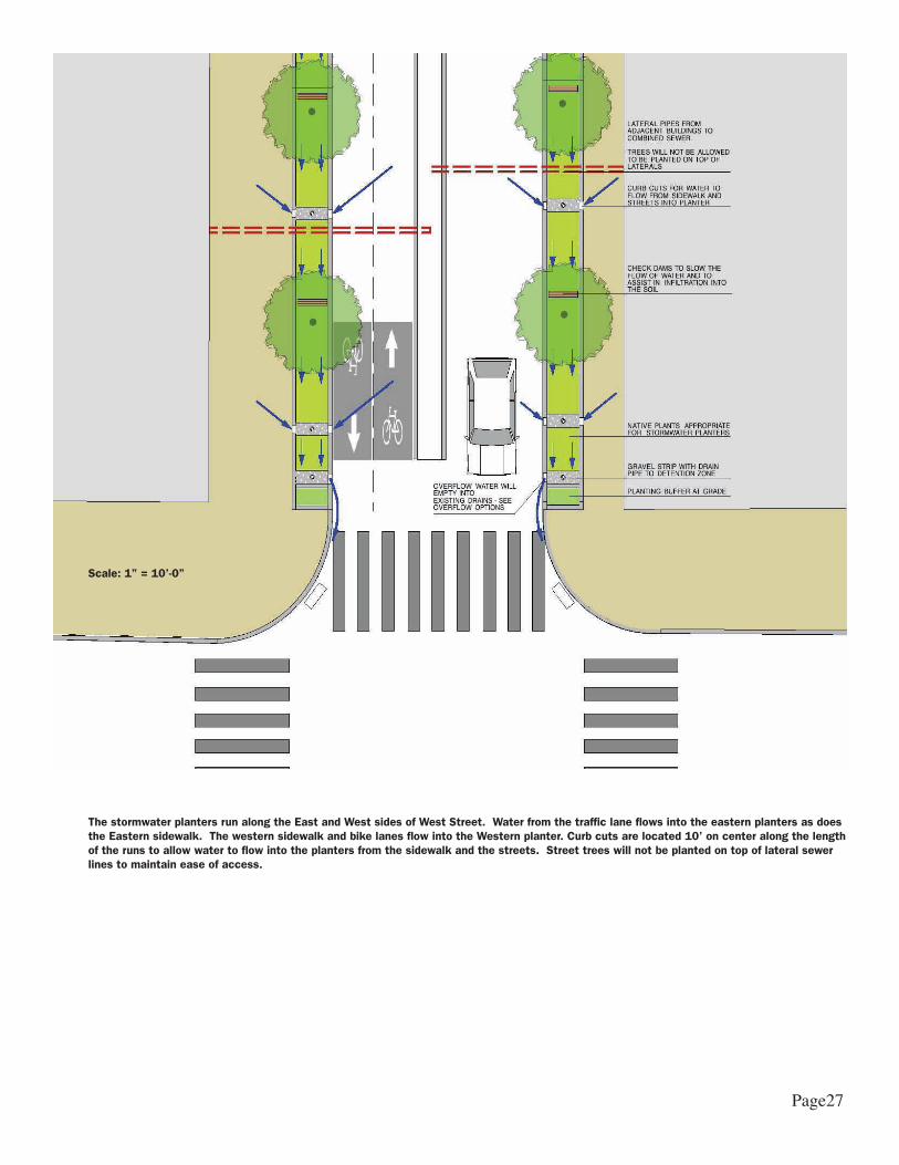
The stormwater planters run along the East and West sides of West Street. Water from the traffic lane flows into the eastern planters as does the Eastern sidewalk. The western sidewalk and bike lanes flow into the Western planter. Curb cuts are located 10’ on center along the length of the runs to allow water to flow into the planters from the sidewalk and the streets. Street trees will not be planted on top of lateral sewer lines to maintain ease of access.
Scale: 1” = 10’-0”
Page27
BLUESTONE AGGREGATE TO SLOW DOWN FLOW OF WATER AND INCREASE INFILTRATION
1'-0
"2'-0
"1'-0
"
CONCRETE CURB - 1" HIGH
RETENTION WEDGE
PERFORATED PVC PIPE FOR DRAINAGE AND STORAGE
HIGH INFILTRATION SOIL - 2'
BLUESTONE AGGREGATE - 1'
CHECK DAMS
* Number and size of pipes and aggregate materials will be determined by final design engineering
DESIGN - PHASE 1 - WEST STREET 6.1
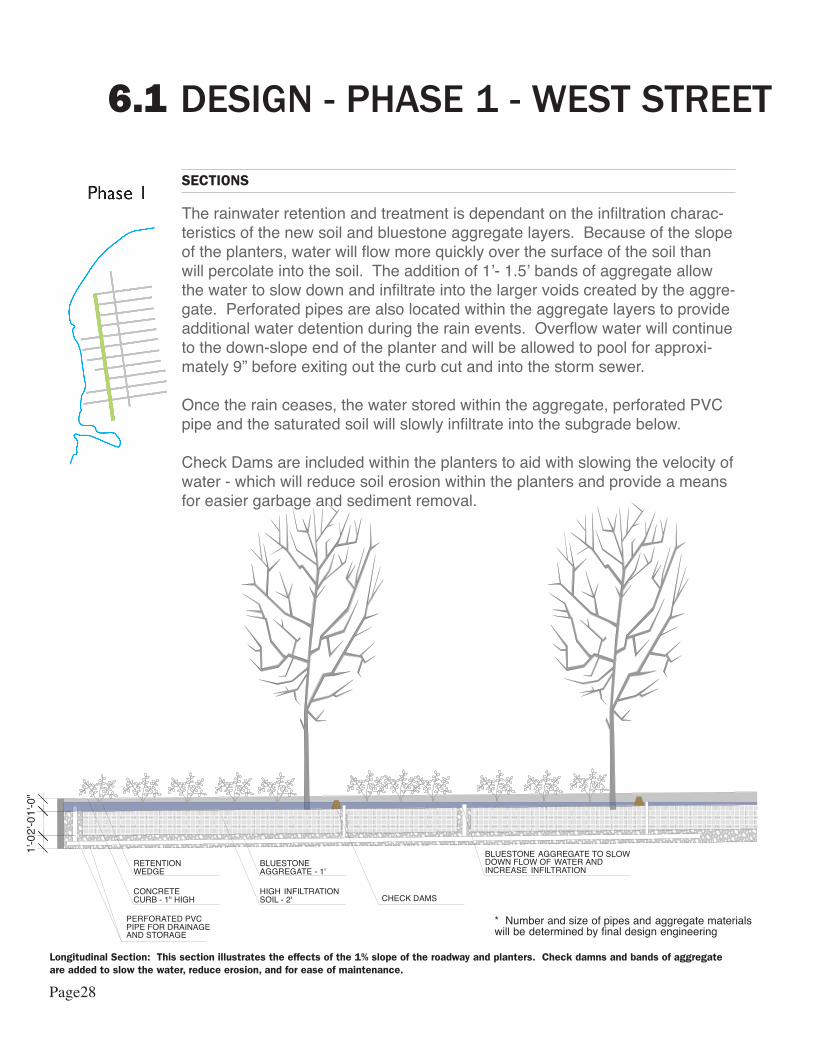
SECTIONS
The rainwater retention and treatment is dependant on the infiltration charac-teristics of the new soil and bluestone aggregate layers. Because of the slope of the planters, water will flow more quickly over the surface of the soil than will percolate into the soil. The addition of 1’- 1.5’ bands of aggregate allow the water to slow down and infiltrate into the larger voids created by the aggre-gate. Perforated pipes are also located within the aggregate layers to provide additional water detention during the rain events. Overflow water will continue to the down-slope end of the planter and will be allowed to pool for approxi-mately 9” before exiting out the curb cut and into the storm sewer.
Once the rain ceases, the water stored within the aggregate, perforated PVC pipe and the saturated soil will slowly infiltrate into the subgrade below.
Check Dams are included within the planters to aid with slowing the velocity of water - which will reduce soil erosion within the planters and provide a means for easier garbage and sediment removal.
Longitudinal Section: This section illustrates the effects of the 1% slope of the roadway and planters. Check damns and bands of aggregate are added to slow the water, reduce erosion, and for ease of maintenance.
Page28
INTERCEPTOR SEWER IS 20 +/-
Water table line: -5' +/- from ground plane
Water table line: -5' +/- from ground plane
COMBINED SEWER
30'-0"
WATER LINE
INTERCEPTOR SEWER IS DEEP BUT IS CLOSE TO THE SIDEWALK IN THE EAST - WEST DIRECTION
AN OLD COMBINED SEWER RUNS ALONG THE CENTER OF THE STREET AND IS RELATIVELY SHALLOW - APPROXIMATELY 7' BELOW THE SURFACE GRADE
60'-0"
THERE ARE A MYRIAD OF UTILITY STRUCTURES UNDERGOUND INCLUDING WATER LINES, ELECTRICAL LINES AND GAS LINES
5'-0
"
15' SIDEWALKS 15' SIDEWALKS
ADJACENT BUILDINGSMANUFACTURING
ADJACENT BUILDINGSMANUFACTURING / RESIDENTIAL
7'-6 1
/2"
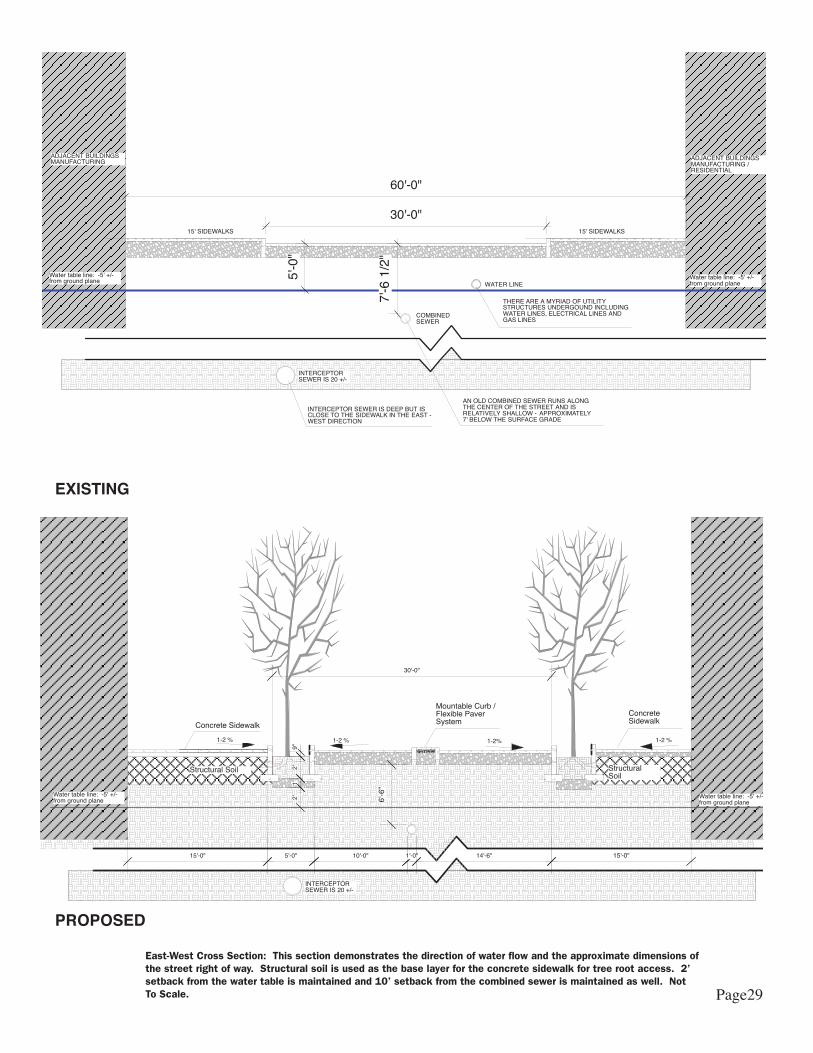
EXISTING
PROPOSED
East-West Cross Section: This section demonstrates the direction of water flow and the approximate dimensions of the street right of way. Structural soil is used as the base layer for the concrete sidewalk for tree root access. 2’ setback from the water table is maintained and 10’ setback from the combined sewer is maintained as well. Not To Scale.
10'-0"15'-0" 1'-0" 14'-6"
INTERCEPTOR SEWER IS 20 +/-
1-2 %1-2%1-2 %
Water table line: -5' +/- from ground plane
1-2 %
Water table line: -5' +/- from ground plane
Structural Soil Structural Soil
5'-0"
9"
1'
30'-0"
2'
2'
6'-6
"
Concrete Sidewalk
Concrete Sidewalk
Mountable Curb / Flexible Paver System
15'-0"
Page29
PHASE 1 - WEST STREET WITH SECONDARY TREATMENT OPTIONS6.2
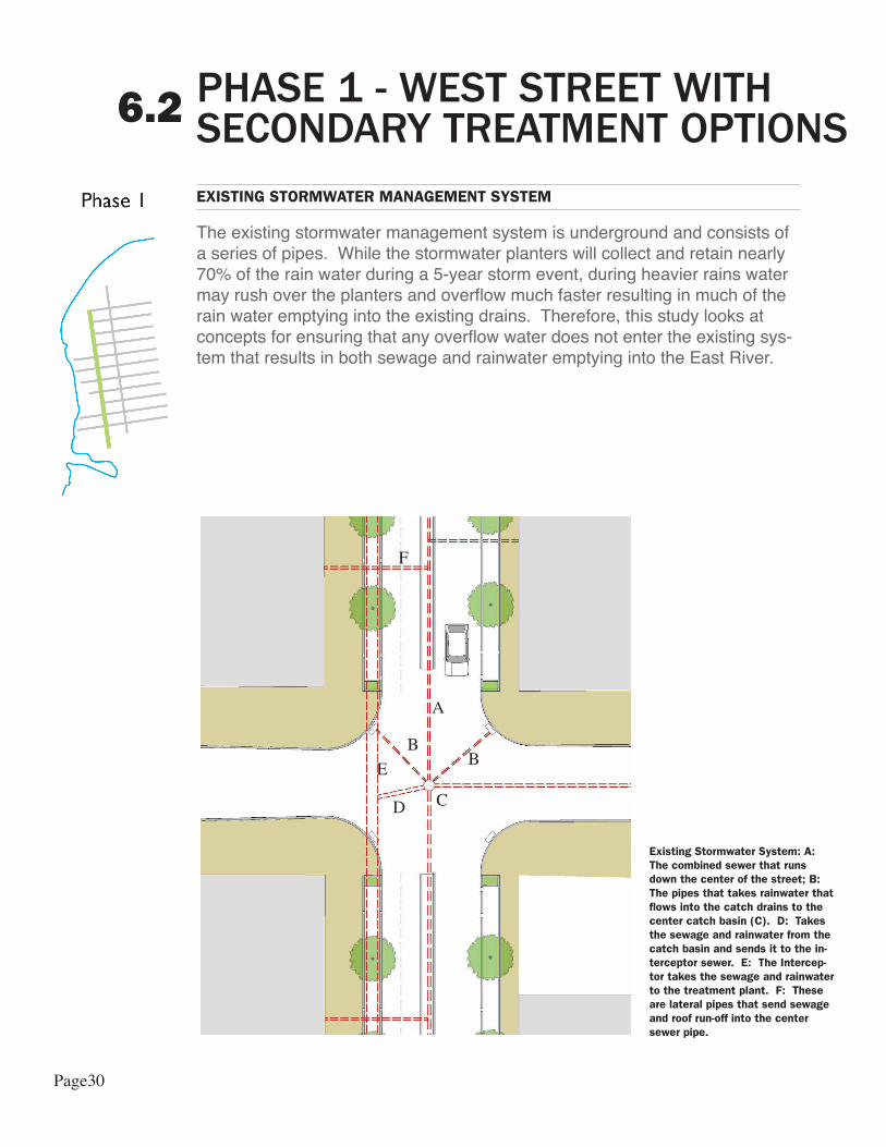
EXISTING STORMWATER MANAGEMENT SYSTEM
The existing stormwater management system is underground and consists of a series of pipes. While the stormwater planters will collect and retain nearly 70% of the rain water during a 5-year storm event, during heavier rains water may rush over the planters and overflow much faster resulting in much of the rain water emptying into the existing drains. Therefore, this study looks at concepts for ensuring that any overflow water does not enter the existing sys-tem that results in both sewage and rainwater emptying into the East River.
A
BB
CD
E
F
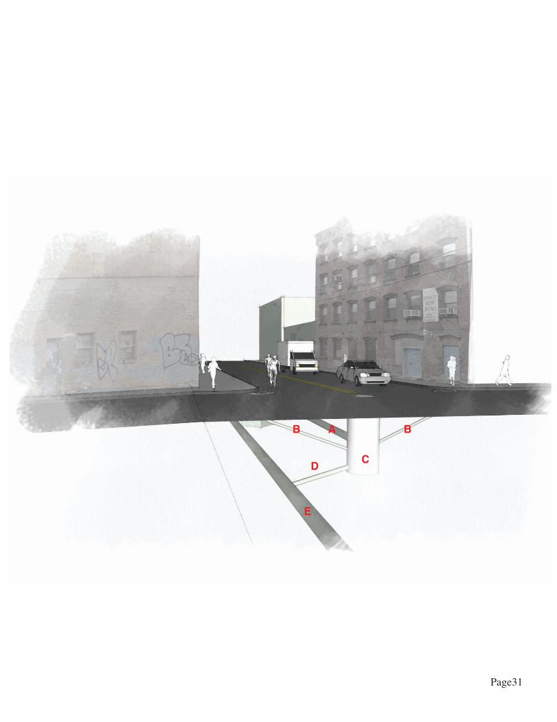
Existing Stormwater System: A: The combined sewer that runs down the center of the street; B: The pipes that takes rainwater that flows into the catch drains to the center catch basin (C). D: Takes the sewage and rainwater from the catch basin and sends it to the in-terceptor sewer. E: The Intercep-tor takes the sewage and rainwater to the treatment plant. F: These are lateral pipes that send sewage and roof run-off into the center sewer pipe.
Page30
AB B
CD
E
Page31
PHASE 1 - WEST STREET WITH SECONDARY OPTIONS6.2
BEYOND THE WEIR
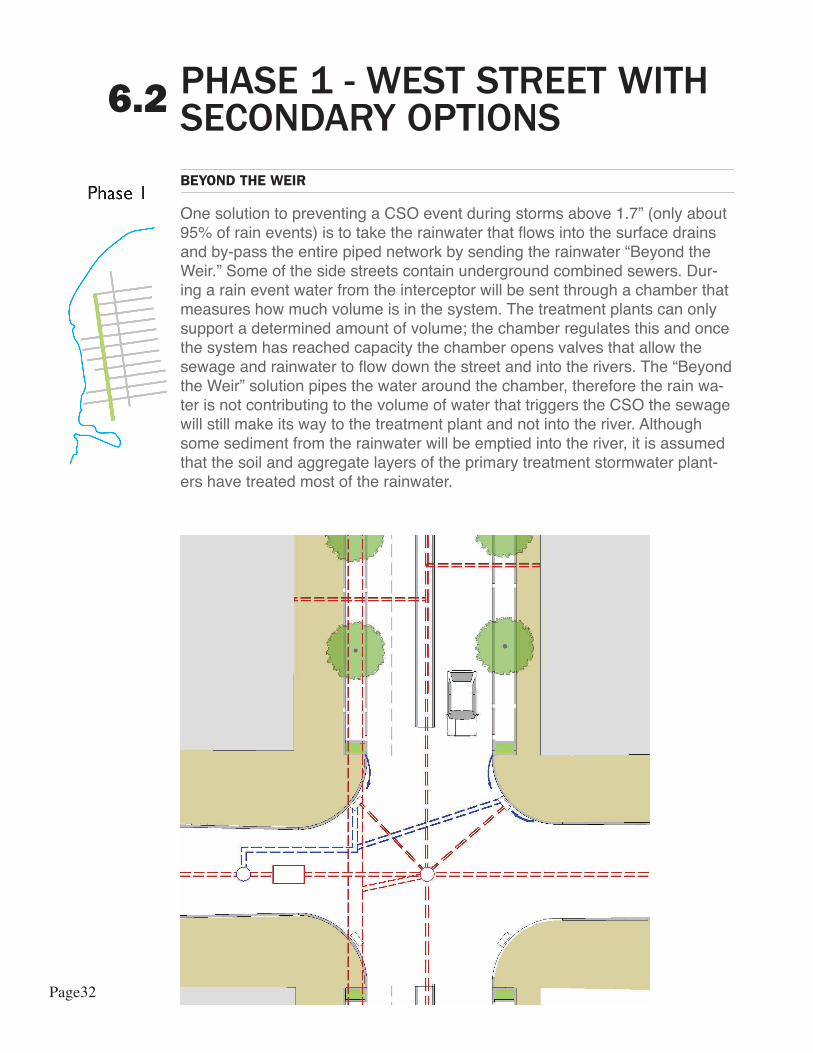
One solution to preventing a CSO event during storms above 1.7” (only about 95% of rain events) is to take the rainwater that flows into the surface drains and by-pass the entire piped network by sending the rainwater “Beyond the Weir.” Some of the side streets contain underground combined sewers. Dur-ing a rain event water from the interceptor will be sent through a chamber that measures how much volume is in the system. The treatment plants can only support a determined amount of volume; the chamber regulates this and once the system has reached capacity the chamber opens valves that allow the sewage and rainwater to flow down the street and into the rivers. The “Beyond the Weir” solution pipes the water around the chamber, therefore the rain wa-ter is not contributing to the volume of water that triggers the CSO the sewage will still make its way to the treatment plant and not into the river. Although some sediment from the rainwater will be emptied into the river, it is assumed that the soil and aggregate layers of the primary treatment stormwater plant-ers have treated most of the rainwater.
Page32
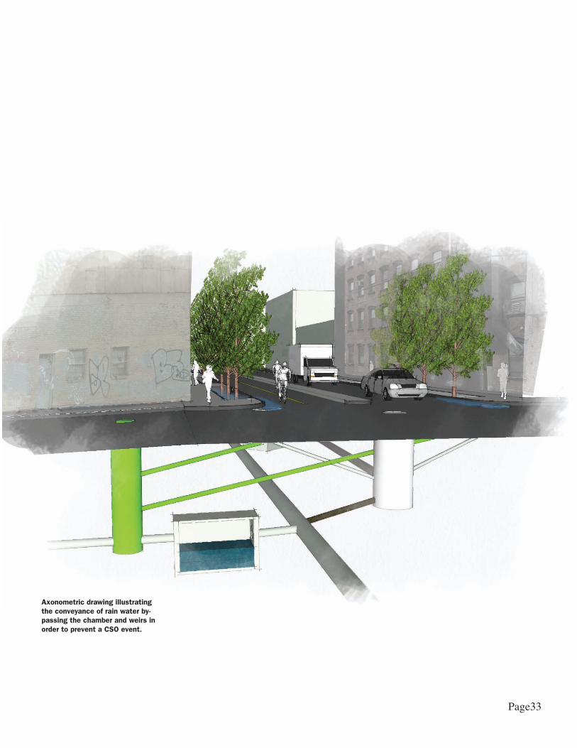
Axonometric drawing illustrating the conveyance of rain water by-passing the chamber and weirs in order to prevent a CSO event.
Page33
PHASE I - WEST STREET WITH SECONDARY OPTIONS6.2
HIGH LEVEL STORM SEWER
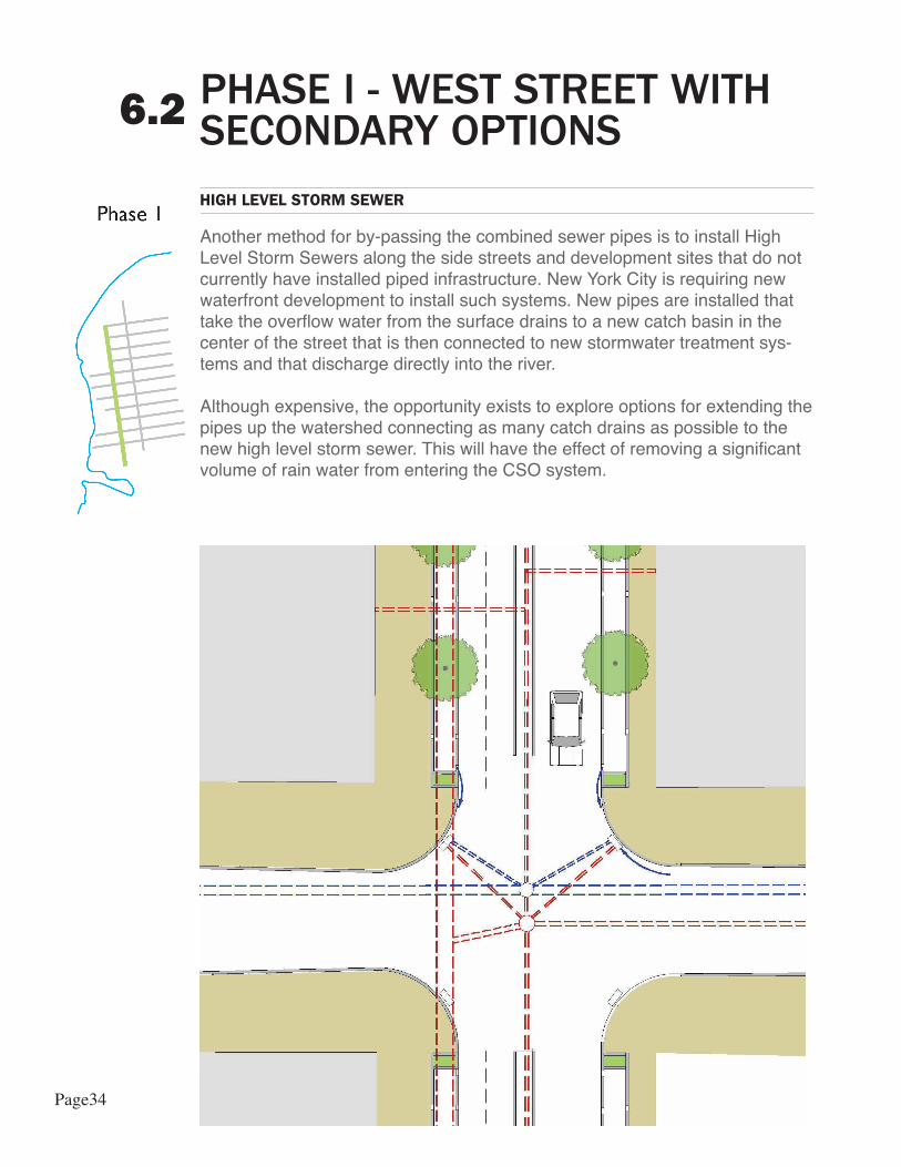
Another method for by-passing the combined sewer pipes is to install HighLevel Storm Sewers along the side streets and development sites that do not currently have installed piped infrastructure. New York City is requiring new waterfront development to install such systems. New pipes are installed that take the overflow water from the surface drains to a new catch basin in the center of the street that is then connected to new stormwater treatment sys-tems and that discharge directly into the river.
Although expensive, the opportunity exists to explore options for extending thepipes up the watershed connecting as many catch drains as possible to thenew high level storm sewer. This will have the effect of removing a significant volume of rain water from entering the CSO system.
Page34
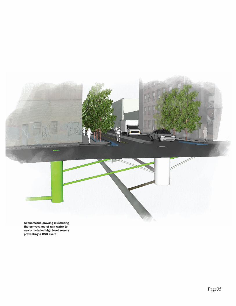
Axonometric drawing illustrating the conveyance of rain water to newly installed high level sewers preventing a CSO event
Page35
PHASE I - WEST STREET WITH SECONDARY OPTIONS6.2
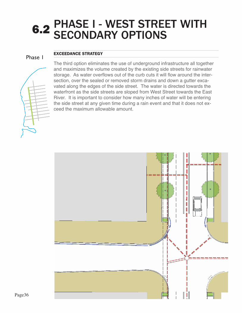
EXCEEDANCE STRATEGY
The third option eliminates the use of underground infrastructure all together and maximizes the volume created by the existing side streets for rainwater storage. As water overflows out of the curb cuts it will flow around the inter-section, over the sealed or removed storm drains and down a gutter exca-vated along the edges of the side street. The water is directed towards the waterfront as the side streets are sloped from West Street towards the East River. It is important to consider how many inches of water will be entering the side street at any given time during a rain event and that it does not ex-ceed the maximum allowable amount.
Page36
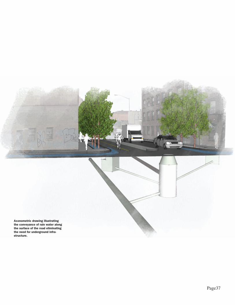
Axonometric drawing illustrating the conveyance of rain water along the surface of the road eliminating the need for underground infra-structure.
Page37

DESIGN - PHASE II - INCREMENTAL DEVELOPMENT6.3
OVERVIEW
During Phase II and Phase III the treatment train can be maximized. Rain-water will flow through the stormwater planters on West Street and then flow through connected, surface treatments along the side streets. Any additional water is collected and retained in waterfront parks, street-end parks, and inter-tidal habitats.
Page38

Page39
DESIGN - PHASE III - COMPLETE STORMWATER MANAGEMENT NET-WORK
6.4
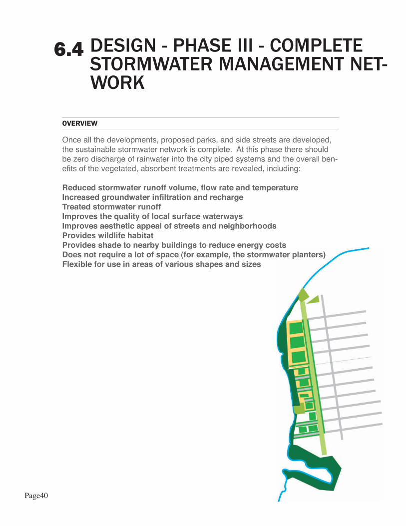
OVERVIEW
Once all the developments, proposed parks, and side streets are developed, the sustainable stormwater network is complete. At this phase there should be zero discharge of rainwater into the city piped systems and the overall ben-efits of the vegetated, absorbent treatments are revealed, including:
Reduced stormwater runoff volume, flow rate and temperatureIncreased groundwater infiltration and rechargeTreated stormwater runoffImproves the quality of local surface waterwaysImproves aesthetic appeal of streets and neighborhoodsProvides wildlife habitatProvides shade to nearby buildings to reduce energy costs Does not require a lot of space (for example, the stormwater planters)Flexible for use in areas of various shapes and sizes
Page40

PHASE 1 - EXIST-ING CONDITION
PLANTERS - FLOW THROUGH
PRIMARY SECONDARY
PLANNING STRATEGIES
PLANTERS - FLOW THROUGH w/ DE-TENTION
INFILTRATION PLANTERS
BEYOND THE WEIR
NEW HIGH LEVEL SEWER - PRIVATE OR PUBLIC
EXCEEDANCE - SURFACE DETENTION
DETENTION TANK
PLANTERS - FLOW THROUGH
GREENSTREETS-
TERTIARY
EXISTING PUBLIC WATERFRONT PARK
PHASE 2 AND PHASE 3 - INCREMENTAL DEVELOP-MENT
SWALES
INFILTRATION PLANTERS
WETLANDS
SHORELINE RES-TORATION / REVET-MENT POOLS
RAIN GARDENS
PHASING STRATEGIES
NEXT STEPS AND RECOMMENDATIONS7.0
OVERVIEWOVERVIEW
The analysis presented here shows that the concept of using sustainable storm drainage BMPs to reduce runoff during storm events is a viable idea. In order to move toward a design of such a system additional information would be required, such as a topographic survey of the subject site and some level of soils investigation. Once this additional data is obtained, and the scope of design is defined, a complete storm drainage study and design can be completed and submitted to appropriate agencies for review and approval. The following diagram demonstrates the sustainable stormwater planning strategies as the waterfront zoning transitions from its current to future land uses.
Page41

MAINTENANCE8.0
MAINTENANCE OVERVIEW
An extensive maintenance business and operations plan is needed to en-sure the commitments by multiple public, private and non-profit entities. The Brooklyn Greenway Initiative and the Regional Plan Association have begun this investigation through the publication of the Brooklyn Greenway Steward-ship Plan (Winter, 2008). For the purpose of this sustainable stormwater study, specific maintenance tasks are identified along with their associated time commitments. For example, debris removal should be conducted on a weekly basis. This list serves as a guide and will need to be refined as the design for West Street is progressed.
Stormwater Planters maintenance tasks.
MAINTENANCE ITEM DAILY WEEKLY MONTHLY QUARTERLY YEARLY AS NEEDED RESPONSIBLE PARTIES
WATERING - FIRST TWO YEARS
During Hot SpellsBGI and/or other local Non-Profit Stewardship entity, under contract with DPR.
WATERING - AFTER THE FIRST TWO YEARS
Only during the hottest days
BGI and/or other local Non-Profit Stewardship entity, under contract with DPR.
WEEDINGDuring the Summer and
Fall BGI and/or other local Non-Profit Stewardship entity, under contract with DPR.
SOIL REPLACEMENT BGI and/or other local Non-Profit Stewardship entity, under contract with DPR.
PRUNING AND TRIMMING
Trees and plants adjacent to street and bike lanes
BGI and/or other local Non-Profit Stewardship entity, under contract with DPR.
PEST CONTROLBGI and/or other local Non-Profit Stewardship entity, with DPR training.
DEBRIS REMOVALBGI and/or other local Non-Profit Stewardship entity.
SEDIMENT AND SALT REMOVAL - AT INFLOW
AND OUTFLOW MECHANISMS
More often if there are storm events
Salt removal after snow events
BGI and/or other local Non-Profit Stewardship entity. Under contract with DPR.
FALL / WINTER CLEAN-UP Adding mulch, removing
annuals, weeding
BGI and/or other local Non-Profit Stewardship entity, under contract with DPR
PLANT REPLACEMENTDPR
CONTAMINATION TESTING - SOIL AND
PLANTS
University or local Non-Profit with DEP and DPR oversight.
PERIODIC REPLACEMENT OF
CONCRETE STRUCTURES
DOT and/or DEP to be resolved
MAINTENANCE MONITORING
Local Non-Profit with Stormwater Task Force input and DEP and DPR oversight.
Page42
This project crosses bureaucratic jurisdictions outside of the “business-as-usual” operations of the City. There is a need to forge cooperative relationships amongst City agencies, private interests as well as neighborhood groups and citizens to ensure adequate maintenance of the system over time. The chart on the preceding page lays out the specific tasks and time commitments while identifying the responsible party for each task.
A critical need is for a local, non-profit stewardship entity to help coordinate the efforts needed to maintain the stormwater system. Brooklyn Greenway Initiative (BGI) is poised to become the primary stewardship entity for the built Greenway. Where appropriate, the group will enter into cooperative agreements with relevant city agencies - including DPR, DOT and DEP – and will work closely with other partners in stewardship including universities and other local non-profits. Together, plans for stewardship of segments of the greenway will be developed and followed to ensure proper mainte-nance for the life of the greenway.
The following cost estimates are for the stormwater management system that would be developed as “Primary Treatment.” In addition to being the most critical stormwater capture facility described, it is also the system that requires the greatest interagency stewardship coordination as mentioned above.
The costs to maintain the “Primary Treatment” approach reflect the need to manage flow through and infiltration planters installed along West Street sidewalk. There are currently no similar systems in New York City. These estimates are based on the estimates developed for similar facilities at Green-streets managed by DPR on DOT property; and comparable bio-filtration systems outside of New York City.
DPR estimates the annual maintenance cost of its Greenstreets facilities to be $3.00 per square foot. This estimate does not account for periodic sediment removal from the inflow and outflow mecha-nisms, which would add a small but recurring cost.
In Portland, OR, cost evaluation for a similar facility as proposed in this report found that maintaining such a system will be higher during the first two years as the facility becomes established and then will level out over time. They found costs to be about $4.00 per square foot per year for the first two years. Once the facility was established, maintenance costs dropped to $1.30 per square foot per year.
With approximately 18,000 square feet of planters envisioned for West Street, and adjusted for New York City conditions, that would translate to around $54,000/year to maintain based on the Green-street cost per square foot. With a stewardship entity in place, along with cooperative agreements with City agencies, private support and the work of volunteers, these annual costs can be distributed amongst a number of partners.
MAINTENANCE COOPERATION
ESTIMATED MAINTENANCE COSTS
Page43
REFERENCES
Brooklyn Greenway Initiative: http://www.brooklyngreenway.org/
Regional Plan Association: http://www.rpa.org
Stormwater Management Plan: 2008: A Greener Greater New York: http://www.nyc.gov/html/planyc2030/html/stormwater/stormwater.shtml
Stormwater Infrastructure Matters SWIM: http://swimmablenyc.info/
Greenpoint Williamsburg Rezoning: http://www.nyc.gov/html/dcp/html/green-pointwill/greenoverview.shtml
Portland Stormwater Information: http://www.portlandonline.com/BES/index.cfm?c=34598
New York City Department of Environmental Protection: http://www.nyc.gov/html/dep/html/home/home.shtml
US Environmental Protection Agency: http://cfpub.epa.gov/npdes/stormwater/menuofbmps/index.cfm?action=browse
Queens Botanical Garden: http://www.queensbotanical.org/103498/sustain-able/sustainable_systems/water
Minnesota Pollution Control Agency: http://www.pca.state.mn.us/publications/manuals/stormwaterplants.html
REFERENCES9.0
Page44

This Page Intentionally Left Blank

This Page Intentionally Left Blank

This Page Intentionally Left Blank

Regional Plan Association (RPA) is an independent regional planning organization that improves the quality of life and the economic competitiveness of the 31-county, New York-New Jersey-Connecticut region through research, planning, and advocacy. Since 1922, RPA has been shaping transportation systems, protecting open spaces, and promoting better com-munity design for the region's continued growth. We anticipate the challenges the region will face in the years to come, and we mobilize the region's civic, business, and government sectors to take action.
RPA’s current work is aimed largely at implementing the ideas put forth in the Third Regional Plan, with efforts focused in five project areas: community design, open space, trans-portation, workforce and the economy, and housing. For more information about Regional Plan Association, please visit our website, www.rpa.org.
Chairman Elliot G. Sander
Vice Chairman and Co-Chairman, New JerseyChristopher J. Daggett
Vice Chairman Douglas Durst
Vice Chairman and Co-Chairman, New JerseyHon. James J. Florio
Vice Chairman and Co-Chairman, Connecticut John S. Griswold, Jr.
Treasurer and Co-Chairman, Long IslandMatthew S. Kissner
Chairman Emeritus and CounselPeter W. Herman
President Robert D. Yaro
Executive DirectorThomas K. Wright
Bradley AbelowHilary M. BallonLaurie BeckelmanStephen R. BeckwithPaul CamutiFrank S. CiceroJudith D. CooperKevin S. CorbettAlfred A. DelliBoviBrendan P. DougherRuth F. DouzinasBrendan J. DuganFernando FerrerBarbara J. FifePaul FrancisTimur F. GalenJerome W. GottesmanMaxine GriffithJohn K. HalveyDylan HixonDavid HuntingtonAdam IslesKenneth T. JacksonMarc JosephRichard D. KaplanRobert KnappJohn Z. KukralRichard C. LeoneCharles J. MaikishJoseph J. Maraziti, Jr.J. Andrew MurphyJan Nicholson
Bruce P. NolopMichael O’BoyleVicki O’MearaKevin J. PearsonJames S. PolshekGregg RechlerMichael J. ReganThomas L. RichDenise RichardsonRebecca R. RileyMichael M. RobertsClaire M. RobinsonElizabeth Barlow RogersLynne B. SagalynLee B. SchroederRobert A. ScottH. Claude ShostalSusan L. SolomonThomas J. Stanton IIILuther Tai Marilyn J. TaylorSharon C. TaylorRichard T. ThigpenTimothy J. TouheyKaren E. WagnerWilliam M. YaroJohn Zuccotti
4 Irving Place, 7th floorNew York, NY 10003212.253.2727fax 212.253.5666
Two Landmark Square, Suite 108Stamford, CT 06901203.356.0390fax 203.356.0390
179 Nassau Street, 3rd floorPrinceton, NJ 08542609.228.7080fax 609.228.7079
BOARD OF DIRECTORS
Brooklyn Greenway Initiative145 Columbia StreetBrooklyn, NY 11231www.brooklyngreenway.org
Noah BudnickMichael CairlDonald CapocciaTom Fox
Raymond Hall Robert A. LevineRobert PiraniPaul J. Proulx, Esq.
Milton PuryearJoseph Vance
BOARD OF DIRECTORS


