By Authority Of THE UNITED STATES OF AMERICA Legally Binding Document By the Authority Vested By Part 5 of the United States Code § 552(a) and Part 1 of the Code of Regulations § 51 the attached document has been duly INCORPORATED BY REFERENCE and shall be considered legally binding upon all citizens and residents of the United States of America. HEED THIS NOTICE : Criminal penalties may apply for noncompliance. Official Incorporator : THE EXECUTIVE DIRECTOR OFFICE OF THE FEDERAL REGISTER WASHINGTON, D.C. Document Name: CFR Section(s): Standards Body: e International Organization for Standardization 49 CFR 171.7 ISO 11119-2: Gas cylinders—Gas cylinders of composite construction—Specification and test methods—Part 2: Fully wrapped fibre reinforced composite gas cylinders with load-sharing metal liners
Transcript
By Authority OfTHE UNITED STATES OF AMERICA
Legally Binding Document
By the Authority Vested By Part 5 of the United States Code § 552(a) and Part 1 of the Code of Regulations § 51 the attached document has been duly INCORPORATED BY REFERENCE and shall be considered legally binding upon all citizens and residents of the United States of America. HEED THIS NOTICE: Criminal penalties may apply for noncompliance.
Official Incorporator:THE EXECUTIVE DIRECTOROFFICE OF THE FEDERAL REGISTERWASHINGTON, D.C.
Document Name:
CFR Section(s):
Standards Body:
e
International Organization for Standardization
49 CFR 171.7
ISO 11119-2: Gas cylinders—Gas cylinders ofcomposite construction—Specification and testmethods—Part 2: Fully wrapped fibre reinforcedcomposite gas cylinders with load-sharingmetal liners
INTERNATIONAL STANDARD
ISO 11119-2
First edition 2002-05-15
Gas cylinders of composite construction -Specification and test methods -
Part 2: Fully wrapped fibre reinforced composite gas cylinders with load-sharing metal liners
Bouteilles a gaz composites - Specifications et methodes d'essai -
Pariie 2: Bouteilles a gaz composites entierement bobinees renforcees par des liners metalliques transmettant fa charge
This PDF file may contain embedded typefaces. In accordance with Adobe's licensing policy, this file may be printed or viewed but shall not be edited unless the typefaces which are embedded are licensed to and installed on the computer performing the editing. In downloading this file, parties accept therein the responsibility of not infringing Adobe's licensing policy. The ISO Central Secretariat accepts no liability in this area.
Adobe is a trademark of Adobe Systems Incorporated.
Details of the software products used to create this PDF file can be found in the General Info relative to the file; the PDF-creation parameters were optimized for printing. Every care has been taken to ensure that the file is suitable for use by ISO member bodies. In the unlikely event that a problem relating to it is found, please inform the Central Secretariat at the address given below.
All rights reserved. Unless otherwise specified, no part of this publication may be reproduced or utilized in any form or by any means, electronic or mechanical, including photocopying and microfilm, without permission in writing from either ISO at the address below or ISO's member body in the country of the requester.
ISO copyright office Case postale 56. CH-1211 Geneva 20 Tel. + 41227490111 Fax + 41 227490947 E-mail [email protected] Web www.iso.ch
Foreword ..................................................................................................................................................................... iv
Introduction ................................................................................................................................................................. v
Annex A (informative) Examples of design approval certificate .......................................................................... 25
Annex B (informative) Specimen test reports ........................................................................................................ 26
ISO (the International Organization for Standardization) is a worldwide federation of national standards bodies (ISO member bodies). The work of preparing International Standards is normally carried out through ISO technical committees. Each member body interested in a subject for which a technical committee has been established has the right to be represented on that committee. International organizations, governmental and non-governmental, in liaison with ISO, also take part in the work. ISO collaborates closely with the International Electrotechnical Commission (IEC) on all matters of electrotechnical standardization.
International Standards are drafted in accordance with the rules given in the ISOIIEC Directives, Part 3.
The main task of technical committees is to prepare International Standards. Draft International Standards adopted by the technical committees are circulated to the member bodies for voting. Publication as an International Standard requires approval by at least 75 % of the member bodies casting a vote.
Attention is drawn to the possibility that some of the elements of this part of ISO 11119 may be the subject of patent rights. I SO shall not be held responsible for identifying any or all such patent rights.
ISO 11119-2 was prepared by Technical Committee ISOITC 58, Gas cylinders, Subcommittee SC 3, Cylinder design.
ISO 11119 consists of the following parts, under the general title Gas cylinders of composite construction -Specification and test methods:
Part 1: Hoop wrapped composite gas cylinders
Part 2: Fully wrapped fibre reinforced composite gas cylinders with load-sharing metal liners
Part 3: Fully wrapped fibre reinforced composite gas cylinders with non-metallic and non-load-sharing metal liners
Annexes A and B of this part of ISO 11119 are for information only.
The purpose of ISO 11119 is to provide a specification for the design, manufacture, inspection and testing of a cylinder for world-wide usage. The objective is to balance design and economic efficiency against international acceptance and universal utility.
ISO 11119 aims to eliminate the concern about climate, duplicate inspection and restrictions currently existing because of lack of definitive International Standards and should not be construed as reflecting on the suitability of the practice of any nation or region.
Gas cylinders of composite construction - Specification and test methods -
Part 2: Fully wrapped fibre reinforced composite gas cylinders with load-sharing metal liners
1 Scope
This part of ISO 11119 specifies requirements for composite gas cylinders up to and including 450 litres water capacity, for the storage and conveyance of compressed or liquefied gases with test pressures up to and including 650 bar 1). The cylinders are constructed in the form of a seamless metallic liner over-wrapped with carbon fibre or aramid fibre or glass fibre (or a mixture thereof) in a resin matrix, to provide circumferential reinforcement.
This part of ISO 11119 addresses fully wrapped composite cylinders with a load-sharing liner (i.e. a liner that shares the load of the overall cylinder design) and a design life from 10 a to non-limited life. For cylinders with design life in excess of 15 a, and in order for these cylinders to remain in service beyond 15 a, requalification of these cylinders is recommended.
This part of ISO 11119 does not address the design, fitting and performance of removable protective sleeves. Where these are fitted they should be considered separately.
NOTE 1 ISO 11439 applies to cylinders intended for use as fuel containers on natural gas vehicles.
NOTE 2 ISO 11623 covers periodic inspection and retesting of composite cylinders.
2 Normative references
The following normative documents contain provisions which, through reference in this text, constitute provisions of this part of ISO 11119. For dated references, subsequent amendments to, or revisions of, any of these publications do not apply. However, parties to agreements based on this part of ISO 11119 are encouraged to investigate the possibility of applying the most recent editions of the normative documents indicated below. For undated references, the latest edition of the normative document referred to applies. Members of ISO and lEe maintain registers of currently valid I nternational Standards.
ISO 6506-1 :1999, Metallic materials - Brine" hardness test- Parl1: Test method
ISO 6508-1: 1999, Metallic materials - Rockwell hardness test - Parl1: Test method (scales A, B, C, D, E, F, G, H,K,N, T)
ISO 7225: 1994, Gas cylinders - Precautionary labels
ISO 7866:1999, Gas cylinders - Refillable seamless aluminium al/oy gas cylinders - Design, construction and testing
ISO 9809-1 :1999, Gas cylinders - Refillable seamless steel gas cylinders - Design, construction and testingPart 1: Quenched and tempered steel cylinders with tensile strength less than 1 100 MPa
ISO 9809-2:2000, Gas cylinders - Refillable seamless steel gas cylinders - Design, construction and testing -Part 2 : Quenched and tempered steel cylinders with tensile strength greater than or equal to 1 100 MPa
ISO 11114-1:1997, Transportable gas cylinders - Compatibility of cylinder and valve materials with gas contents - Part 1: Metallic materials
ISO 11439:2000, Gas cylinders - High pressure cylinders for the on-board storage of natural gas as a fuel for automotive vehicles
ISO 13341 :1997, Transportable gas cylinders - Fitting of valves to gas cylinders
ISO 13769 2), Gas cylinders - Stamp marking
EN 1964-3:2000, Transportable gas cylinders - Specification for the design and construction of refillable transportable seamless steel gas cylinders of water capacities from 0,5 litre up to and including 150 litres - Part 3: Cylinders made of seamless stainless steel with an Rm value of less than 1 100 MPa
ASTM D 2343, Standard Test Method for Tensile Properties of Glass Fiber Strands, Yarns, and Rovings Used in Reinforced Plastics
ASTM D 4018, Standard Test Methods for Properties of Continuous Filament Carbon and Graphite Fiber Tows
SACMA SRM 16R-94, Recommended Test Method for Tow Tensile Testing of Carbon Fibers
3 Terms and definitions
For the purposes of this part of ISO 11119, the following terms and definitions apply.
3.1 aramid fibre continuous filaments of aramid laid up in tow form, used for reinforcement
3.2 autofrettage pressure application procedure which strains the metal liner past its yield point sufficient to cause permanent plastic deformation, and results in the liner having compressive stresses and the fibres having tensile stresses when at zero internal gauge pressure
3.3 batch collective term for a set of homogeneous items or material
NOTE The number of items in a batch may vary according to the context in which the term is used.
3.3.1 batch of liners production quantity of up to 200 finished liners successively produced (plus units required for destructive testing) of the same nominal diameter length, thickness and design, from the same material cast and heat treated to the same conditions of temperature and time
3.3.2 batch of finished cylinders production quantity of up to 200 finished cylinders successively produced (plus finished cylinders required for destructive testing), of the same nominal diameter, length, thickness and design
NOTE The batch of finished cylinders may contain different batches of liners, fibres and matrix materials.
3.4 burst pressure highest pressure reached in a cylinder during a burst test
3.5 carbon fibre continuous filaments of carbon laid up in tow form, used for reinforcement
3.6 composite overwrap the combination of fibres and matrix
3.7 dedicated gas service service in which a cylinder is to be used only with specified gas or gases
3.8 equivalent fibre fibre manufactured from the same nominal raw materials, using the same process of manufacture and having the same physical structure and the same nominal physical properties, and where the average tensile strength and modulus is within ± 5 % of the fibre properties in an approved cylinder design
NOTE Carbon fibres made from the same precursor can be equivalent, but aramid, carbon and glass fibres are not equivalent.
3.9 equivalent liner liner equivalent to a liner in a previously prototype tested cylinder when any of the following apply:
the liner is of the prototype tested design except that it is manufactured in a different factory;
the liner is of the prototype tested design except that it is manufactured using a significantly different process from that used to produce the prototype tested design;
the liner is of the prototype tested design except that it is given a heat treatment outside the limits specified in the prototype tested design
3.10 exterior coating layers of material applied to the cylinder as protection or for cosmetic purposes
NOTE The coating may be clear or pigmented.
3.11 fully wrapped cylinder cylinder reinforced with fibres in a resin matrix to take both circumferential and longitudinal stress
3.12 glass fibre continuous filaments of glass laid up in tow form, used for reinforcement
3.13 liner inner portion of the composite cylinder, comprising a metallic vessel, whose purpose is both to contain the gas and transmit the gas pressure to the fibres
3.14 load-sharing liner liner which has a burst pressure greater than or equal to 5 % of the nominal burst pressure of the finished composite cylinder
3.15 matrix material which is used to bind and hold the fibres in place
4 Symbols
See Table 1.
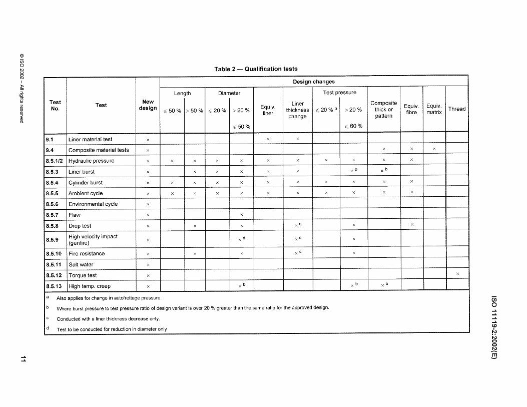
Table 1 - Symbols and their designations
Symbol Designation
Pb Burst pressure of finished cylinder
Pbl Burst pressure of liner
Ph Test pressure
Pmax Maximum developed pressure at 65°C
Pw Working pressure
5 Inspection and testing
Unit
bar
bar
bar
bar
bar
Evaluation of conformity is required to be performed in accordance with the relevant regulations of the country(ies) where the cylinders are used. In order to ensure that the cylinders conform to this part of ISO 11119, they shall be subject to inspection and testing in accordance with clauses 6, 7, 8 and 9 by an authorized inspection body (hereafter referred to as "the inspector") recognized in the country(ies) of use. The inspector shall be competent for the inspection of cylinders.
6 Materials
6.1 liner materials
6.1.1 The liner materials shall conform in all relevant respects to the appropriate standard, as follows:
a) seamless steel liners: ISO 9809-1 or ISO 9809-2, as appropriate;
b) seamless stainless steel liners: EN 1964-3;
c) seamless aluminium alloy liners: ISO 7866.
This excludes the design requirements, since these are specified by the manufacturer for the design of the composite cylinder (see 7.2.2).
NOTE For liners with water a capacity> 150 i the relevant sections of the above standards also apply.
6.1.2 The materials used shall be of uniform and consistent quality. The composite cylinder manufacturer shall verify that each new batch of materials has the correct properties and is of satisfactory quality, and shall maintain records from which the batch of materials used for the manufacture of each cylinder can be identified. A certificate of conformance from the liner material manufacturer is considered acceptable for the purposes of verification.
6.1.3 The cast shall be identified to the satisfaction of the inspector.
6.1.4 The liner shall be manufactured from a metal or alloy suitable for containing the gas (see ISO 11114-1). Furthermore the liner material shall be evaluated by the manufacturer as suitable for the specific application. If the liner material is not covered by ISO 11114-1 for a particular gas/commodity, the responsibility for the approval of material selection should reside with the authority having jurisdiction in the country of use.
6.1.5 When a neck ring is provided, it shall be of a material compatible with that of the cylinder, and shall be securely attached by a method appropriate to the liner material.
6.2 Composite materials
6.2.1 The overwrap filament materials shall be carbon fibre or aramid fibre or glass fibre (or any mixture thereof).
6.2.2 The resin matrix shall be a polymer suited to the application, environment and intended life of the product; e.g., epoxy or modified epoxy with amine or anhydride curing agent, vinyl esters and polyesters.
6.2.3 The supplier of the filament material and the resin system component material shall provide sufficient documentation for the composite cylinder manufacturer to be able to fully identify the batch of materials used in the manufacture of each cylinder.
6.2.4 The materials used shall be of uniform and consistent quality. The composite cylinder manufacturer shall verify that each new batch of materials has the correct properties and is of satisfactory quality, and maintain records from which the batch of materials used for the manufacture of each cylinder can be identified. A certificate of conformance from the material manufacturer is considered acceptable for the purposes of verification.
6.2.5 Batches of materials shall be identified and documented to the satisfaction of the inspector.
6.2.6 The manufacturer shall ensure there is no adverse reaction between the liner and the reinforcing fibre by the application of a suitable protective coating to the liner prior to the wrapping process (if necessary).
7 Design and manufacture
7.1 General
7.1.1 A fully wrapped composite gas cylinder with load-sharing liner shall comprise the following parts:
an internal metal liner, which carries part of the longitudinal and circumferential load;
a composite overwrap formed by layers of continuous fibres in a matrix;
an optional exterior coating to provide external protection. When this is an integral part of the design it shall be permanent.
7.1.2 Cylinders may be designed with one or two openings along the central axis only. Parallel threads shall extend completely through the neck or have sufficient threads to allow full engagement of the valve.
7.1.3 The cylinder may also include additional parts such as rings, bases, etc.
7.1.4 The composite cylinder shall be certified by the inspector. The inspector shall certify that the design, manufacture, inspection and testing were carried out in accordance with this part of ISO 11119. Example forms of certificates are shown in annexes A and B.
7.1.5 The cylinders shall be designed for high reliability under sustained load and cyclic loading. Therefore it is necessary to take account of the properties of the individual composite fibres and to establish their respective minimum fibre stress ratios.
The fibre stress ratio is defined as the fibre stress at calculated design minimum burst pressure divided by the fibre stress at x 2/3 test pressure.
The minimum fibre stress ratios shall be as follows:
for glass - 3,4
for aramid - 3,1
for carbon - 2,4
7.2 Design submission
7.2.1 The design submission for each new design of cylinder shall include a detailed drawing, along with documentation of the design including stress analysis, manufacturing and inspection particulars as detailed in 7.2.2, 7.2.3, 7.2.4 and 7.2.5.
7.2.2 Documentation for the liner shall include:
a) material, including limits of chemical analysis;
b) dimensions, minimum thickness, straightness and out-of-roundness with tolerances;
c) process and specification of manufacture;
d) heat-treatment, temperatures, duration and tolerances;
e) inspection procedures (minimum requirements);
f) material properties (mechanical properties requirements);
g) minimum design burst pressure;
h) dimensional details of valve threads and any other permanent features.
7.2,3 Documentation for the composite overwrap shall include:
a) fibre material, specification and mechanical properties requirements;
b) fibre construction, strand-geometry and treatment;
c) resin system, main components and resin bath temperature where applicable;
d) resin system, curing agent, materials and specifications where applicable;
e) resin system, accelerator, materials and specifications where applicable;
f) overwrap construction including the number of strands used;
g) curing process, temperatures, duration and tolerances.
7.2.4 Documentation for the composite cylinder shall include:
a) water capacity in litres;
b) list of intended contents if intended for dedicated gas service;
c) working pressure, Pw (if applicable and which shall not exceed test pressure x 2/3);
d) composite cylinder test pressure, Ph;
e) maximum developed pressure at 65°C for specific dedicated gas(es), Pmax;
f) design life in years; cylinders with a test pressure of less than 60 bar shall have a non-limited design life;
g) autofrettage pressure and approximate duration (where applicable);
h) tensioning of the fibre at winding (where applicable);
i) weight.
7.2.5 Stress analysis shall be carried out and documentation provided in accordance with the following.
The stresses in the composite material(s) and in the liner shall be calculated using appropriate finite element stress analysis or other stress analysis programmes, which take into account the non-linear material behaviour of the liner. The nominal thickness and nominal properties of the respective materials shall be used for the calculations.
A table summarizing the stresses at zero, test pressure x 2/3, test pressure and design minimum burst pressure shall be provided.
The fibre stress ratio(s) for the design shall exceed those stated in 7.1.5.
NOTE There is no standardized calculation method for the stress analysis. Therefore the objective of this clause is to demonstrate only that the design stress ratios have been met.
7.3 Manufacturing
7.3.1 The liner shall be manufactured in accordance with the manufacturer's design (see 7.2.2) and the International Standard for the relevant metallic material (as listed in 6.1.1).
7.3.2 The composite cylinder shall be fabricated from a load-sharing liner fully over-wrapped with resinimpregnated continuous fibres. Winding shall be applied in the longitudinal and circumferential directions under controlled tension to in order to develop the design composite thickness and as specified in the documentation in 7.2.3.
Liners may be stripped and re-wound, provided that the overwrap has not been cured. The liner shall not be overwrapped if it has been damaged or scored by the stripping process.
7.3.3 After winding is completed, the composite shall be cured (if appropriate) using a controlled temperature profile as specified in the documentation in 7.2.3 The maximum temperature shall be such that the mechanical properties of the liner material are not adversely affected.
7.3.4 If cylinders are subjected to an autofrettage operation, the autofrettage pressure and duration shall be as specified in the documentation in 7.2.4. The manufacturer shall demonstrate the effectiveness of the autofrettage by appropriate measurement technique(s) acceptable to the inspector.
7.3.5 If cylinders are subjected to a prestressing or fibre tensioning during winding in order to actively change the final stresses in the finished cylinder, the level of stress shall be as specified in the documentation in 7.2.4 and levels of stress of tensioning shall be recorded or monitored.
The design submission of each new design of cylinder shall be submitted by the manufacturer to the inspector. The type approval tests detailed in 8.2 shall be carried out on each new design or design variant under the supervision of the inspector.
8.2 Prototype tests
8.2.1 A minimum of 30 cylinders that are guaranteed by the manufacturer to be representative of the new design shall be made available for prototype testing.
8.2.2 However, if for special applications the total number of cylinders required is less than 30, enough cylinders shall be made to complete the prototype tests required, in addition to the production quantity. Then the approval validity is limited to this batch only.
8.2.3 For a limited design change (design variant), in accordance with Table 2, a reduced number of cylinders may be selected by the inspector.
8.2.4 The inspector shall verify that the batch of liners, prior to being wrapped, conforms to the design requirements and is inspected and tested in accordance with 9.1. Where specified in Table 2, one liner shall be selected and subjected to a burst test in accordance with 8.5.3.
8.2.5 The inspector shall verify that the composite material(s), prior to the cylinders being wrapped, conform to the design requirements and are tested in accordance with 9.3.
8.2.6 The inspector shall verify that all cylinders in the batch produced for new design approval conform to the design submission and are tested in accordance with 9.4.
8.2.7 Except for the cases identified in 8.2.8, the inspector shall supervise the following tests on the cylinders selected:
a) hydraulic proof pressure test, in accordance with 8.5.1 or hydraulic volumetric expansion test, in accordance with 8.5.2;
b) burst test, in accordance with 8.5.4;
c) ambient cycle test, in accordance with 8.5.5;
d) environmental cycle test, in accordance with 8.5.6;
e) flaw test, in accordance with 8.5.7;
f) drop test, in accordance with 8.5.8;
g) high velocity impact (gunfire) test, in accordance with 8.5.9;
h) fire resistance test, if a pressure relief device is fitted to prevent failure in case of fire in service, in accordance with 8.5.10;
i) salt water immersion test, in accordance with 8.5.11;
j) torque test, in accordance with 8.5.12;
k) high temperature creep test, in accordance with 8.5.13.
8.2.8 For variations in design from the new design cylinder as specified in 8.4, it is only necessary to carry out the tests as prescribed in Table 2. A cylinder approval by a reduced series of tests shall not be used as a basis for a second design variant approval with a reduced set of tests (i.e. multiple changes from an approved design are not permitted) although individual test results can be used as applicable (see 8.4.2).
8.2.9 If the results of the verifications in accordance with 8.2.4, 8.2.5, 8.2.6 and either 8.2.7 or 8.2.8, as applicable, are satisfactory, the inspector shall issue a design approval certificate, a typical example of which is given in annex A.
8.2.10 All test cylinders shall be rendered unserviceable after testing has been completed.
8.3 New design
8.3.1 No alteration shall be made to the design or the method of manufacture after approval unless such alteration has received the prior agreement of the inspector.
8.3.2 A new cylinder design requires full qualification testing. A cylinder shall be considered to be of a new design compared with an existing approved design if the method of cylinder manufacture or design has changed to a significant extent, e.g.
a) It is manufactured in a different factory.
The testing required for cylinders after relocation of an existing factory shall be evaluated by the inspector.
b) It is manufactured by a process that is significantly different from the process used in the design qualification.
NOTE A significant change is regarded as a change that would give rise to measurable change in the performance of the liner and/or finished cylinder. The inspector determines when a change in process or design or manufacture is significantly different from the original qualified design.
c) The nominal outside diameter has changed more than 50 % from the qualified design.
d) The composite overwrap materials are significantly different from the qualified design, e.g. different resin system or fibre type.
e) The test pressure has increased more than 60 % from the qualified design.
8.3.3 A cylinder shall also be considered to be of a new design compared with an existing approved design if the method of liner manufacture or design has changed to a significant extent, e.g.
a) It is manufactured in a different factory.
The testing required for liners after relocation of an existing factory shall be evaluated by the inspector.
b) It is manufactured from a material of different composition or composition limits from that used in the original type tests.
c) The material properties are outside the original design limits.
8.4 Design variants
8.4.1 For cylinders similar to an approved design, a reduced qualification testing programme may only be required. A cylinder shall be considered to be a design variant if changes are limited to the following conditions:
a) the nominal length of the cylinder has changed;
b) the nominal outside diameter has changed by less than 50 %;
c) the autofrettage pressure has changed by more than 5 % or 10 bar, whichever is the lower;
d) the base profile and/or base thickness of the liner has changed relative to the cylinder diameter and minimum wall thickness;
e) there is an increase in the design test pressure up to and including 60 %;
NOTE Where a cylinder is to be used and marked for a lower test pressure than that for which design approval has been given, it is not deemed to be of a new design or design variant.
f) there is a minor change in the composite overwrapping thickness (up to 5 %) or the wrapping pattern has changed;
g) the nominal wall thickness of the liner has changed;
h) matrix materials (i.e. resin, curing agent, accelerator) are different but are chemically equivalent to the original design;
i) when equivalent overwrapping fibres are used;
NOTE Where a new equivalent fibre has been prototype tested for an existing design, then all the manufacturer's existing prototype tested designs are regarded as prototype tested with the new fibre without the need for any additional prototype testing.
j) when an equivalent liner material is used the new liner shall
1) be subjected to the material tests specified in 9.1.3 and
2) meet the minimum requirements specified in 7.2.2 and the liner burst test, in accordance with 8.5.3, and shall also meet the minimum requirements of the prototype tested design.
NOTE Where a new equivalent liner has been prototype tested for an existing design, then all the manufacturer's existing prototype tested designs are regarded as prototype tested with the new liner without the need for any additional prototype testing.
k) when the cylinder thread has changed.
When a cylinder design has only a different thread compared to an approved design, only the torque test, in accordance with 8.5.12, shall be carried out.
8.4.2 A cylinder approval by a reduced series of tests (a design variant) shall not be used as a basis for a second design variant approval with a reduced set of tests (i.e. multiple changes from an approved design are not permitted). If a test has been conducted on a design variant (A) that falls within the testing requirements for a second variant (8), then the result for (A) can be applied to the new design variant (8) test programme. However design variant (A) cannot be used as the reference for determining the testing required for any new design variant.
8.4.3 Where a design variant involves more than one parameter change all the tests required by those parameter changes shall be performed once only.
8.4.4 The inspector shall determine the level of reduced testing if not defined in Table 2, but a fully approved design shall always be used as a reference for the new design variant (Le. new design variants shall not be approved by reference only to a previous design variant).
8.5 Qualification test procedures and criteria
8.5.1 Hydraulic proof pressure test
8.5.1.1 Procedure
This test requires that the hydraulic pressure in the cylinder be increased gradually and regularly until the test pressure, Ph, is reached. The cylinder test pressure shall be held for a sufficiently long period (at least 30 s) in order to ascertain that there are no leaks and no failure. If leakage occurs in the piping or fittings, the cylinders may be retested after repairing such leakages.
Where cylinders are subjected to a utofrettage , the hydraulic proof pressure test may be part of or immediately follow the autofrettage process.
a Also applies for change in autofrettage pressure.
b Where burst pressure to test pressure ratio of design variant is over 20 % greater than the same ratio for the approved design.
C Conducted with a liner thickness decrease only.
d Test to be conducted for reduction in diameter only
Composite thick or
Equiv.
pattern fibre
x x
x x
x b
x x
x x
x
x b
Equiv. Thread
matrix
x
x
I
.
I
!
i
I
Ui o ~
~
~
~
(J) I
~ N o o ~ !!3
ISO 11119-2: 2002( E)
8.5.1.2 Criteria
The cylinder shall be rejected if there are leaks, failure to hold pressure or visible permanent deformation after the cylinder is depressurized.
NOTE Cracking of resin is not necessarily a sign of permanent deformation.
8.5.2 Hydraulic volumetric expansion test
8.5.2.1 Procedure
This test requires that the hydraulic pressure in the cylinder be increased gradually and regularly until the test pressure, Ph' is reached. The cylinder test pressure shall be held for a sufficiently long period (at least 30 s) in order to ascertain that there are no leaks and no failure. If leakage occurs in the piping or fittings, the cylinders may be retested after repairing such leakages.
The total volumetric expansion of each cylinder under the test pressure, Ph, and the permanent volumetric expansion of the cylinder after the pressure is released shall be recorded. The elastic expansion (i.e. total expansion less permanent expansion) under test pressure can then be established for each cylinder.
Where cylinders are subjected to a utofrettage , the hydraulic volumetric expansion test may be part of or immediately follow the autofrettage process.
8.5.2.2 Criteria
The cylinder shall be rejected if either:
a) there are leaks or failure to hold pressure or
b) it shows a permanent expansion at zero pressure in excess of 5 % of the total expansion.
8.5.3 Liner burst test
8.5.3.1 Procedure
One cylinder liner shall be tested hydraulically to destruction by pressurizing at a rate of no more than 5 barls. The test shall be carried out under ambient conditions.
Parameters to monitor and record are
a) burst pressure;
b) the number of pieces;
c) description of failure;
d) pressure/time curve or pressure/volume curve.
8.5.3.2 Criteria
The burst pressure of the liner, Pbl' shall be not less than the minimum burst pressure, specified in the design submission 7.2.2. Failure shall initiate in the liner side wall and the liner shall remain in one piece.
Three cylinders shall be tested hydraulically to destruction by pressurizing at a rate of no more than 5 bar/so The test shall be carried out under ambient conditions. Prior to the commencement of the test, it shall be ensured that no air is trapped within the system.
Parameters to monitor and record are
a) burst pressure;
b) description of failure;
c) pressure/time curve or pressure/volume curve.
8.5.4.2 Criteria
The burst pressure of the finished cylinder, Pb, shall be not less than the test pressure, Ph, x 2 of the composite cylinder design.
8.5.5 Am bient cycle test
NOTE It is recommended that no air be trapped within the system prior to the commencement of the test.
8.5.5.1 For cylinders with test pressure equal to or greater than 60 bar
8.5.5.1.1 General
Where a cylinder is intended for use only with one or more specific gases the design may be designated for dedicated gas use. The gases permitted in the cylinder shall be identified clearly on the cylinder label (see 10.2).
8.5.5.1.2 Procedure
Two cylinders shall be subjected to a hydraulic pressure cycle test to test pressure, Ph, for unspecified gas service or maximum developed pressure at 65 °e, Pmax' for the dedicated gas which has the greatest developed pressure.
The test shall be carried out using a non-corrosive fluid under ambient conditions, subjecting the cylinders to successive reversals at an upper cyclic pressure that is equal to the hydraulic test pressure, Ph' or maximum developed pressure at 65 °e, P max' as appropriate.
The value of the lower cyclic pressure shall not exceed 10 % of the upper cyclic pressure, but shall have an absolute maximum of 30 bar. The frequency of reversals of pressure shall not exceed 0,25 Hz (15 cycles per min). The temperature on the outside surface of the cylinder shall not exceed 50 °e during the test.
Parameters to monitor and record are
a) temperature of the cylinder;
b) number of cycles achieving upper cyclic pressure;
The cylinders shall withstand N pressurization cycles to test pressure, Ph, or Nd pressurization cycles to maximum developed pressure, Pmax' without failure by burst or leakage, where:
N = Y x 250 cycles per year of design life
Nd = Y x 500 cycles per year of design life
y is the number of years of design life
y shall be a whole number which is not less than 10 years.
The test shall continue for a further Nor Nd cycles, or until the cylinder fails by leakage, whichever is the sooner. In either case the cylinder shall be deemed to have passed the test. However, should failure during this second part of the test be by burst, then the cylinder shall have failed the test (see Table 3).
If the cylinder is designed to pass 12000 hydraulic cycles to test pressure or 24 000 cycles to maximum developed pressure, and achieves this level consistently in the test, it is not necessary to limit the design life of the cylinder.
NOTE For cylinder without limit in design life the actual service life of the design is subject to conformity assessment.
Table 3 - Criteria for ambient cycle test
1 st part 2nd part
a toN N to 2N but 2lv no more than 12 000 Number of cycles
a tONd Nd to 2Nd but 2Nd no more than 24 000
No leakage/burst = Pass
Criteria No leakage or burst Leakage = Pass
Pass 1 st part Burst = Fail
8.5.5.2 For cylinders with test pressure less than 60 bar
8.5.5.2.1 Procedure
Two cylinders shall be subjected to a hydraulic pressure cycle test to test pressure.
The test shall be carried out using a non-corrosive fluid under ambient conditions, subjecting the cylinders to successive reversals at an upper cyclic pressure that is equal to the hydraulic test pressure, Ph'
The value of the lower cyclic pressure shall not exceed 10 % of the upper cyclic pressure. The frequency of reversals of pressure shall not exceed 0,25 Hz (15 cycles per min). The temperature on the outside surface of the cylinder shall not exceed 50°C during the test.
Parameters to monitor and record are
a) temperature of the cylinder;
b) number of cycles achieving upper cyclic pressure;
The cylinders shall withstand 12 000 pressurization cycles to test pressure, Ph' If the cylinder is designed to pass 12 000 hydraulic cycles to test pressure and achieves this level consistently in the test, it is not necessary to limit the design life of the cylinder.
NOTE For cylinders without limit in design life, the actual service life of the design is subject to conformity assessment.
8.5.6 Environmental cycle test
8.5.6.1 Procedure
One cylinder, as wrapped and without paint or removable protective coating, shall be tested as follows.
Condition cylinder and contained pressurizing medium for 48 h at atmospheric pressure, at a temperature between 60°C and 70 °C and at a relative humidity greater than or equal to 95 %.
The hydraulic pressurizing medium external to the cylinder under test shall commence the cycle testing at ambient temperature. Hydraulically apply 5 000 cycles from a pressure source approximately equal to atmospheric pressure to two-thirds of the test pressure, Ph' The cylinder skin temperature shall be maintained at between 60°C and 70 °C by regulating the environmental chamber and the cycling frequency. The cycling frequency shall not exceed 5 cycles per min.
Release pressure and stabilize cylinder at 20°C approximately.
Stabilize the cylinder and the contained pressurizing medium until the temperature is between - 50 °C and - 60°C.
The hydraulic pressurizing medium external to the cylinder under test shall commence the cycle testing at ambient temperature. Apply 5 000 cycles from a pressure source approximately equal to atmospheric pressure to two-thirds of the test pressure, Ph' The cylinder skin temperature shall be maintained at between - 50 °C and - 60°C by regulating the environmental chamber and the cycling frequency. The cycling frequency shall not exceed 5 cycles per min. The fluid shall also be selected to ensure that it functions at the temperatures specified in the various cycle tests.
Release pressure and stabilize the cylinder at approximately 20 °C. Hydraulically apply 30 cycles from a pressure source approximately equal to atmospheric pressure to the test pressure, Ph'
On completion of these tests, the cylinder is subjected to the burst test in 8.5.4.
Parameters to monitor and record are
a) temperatures during each part;
b) humidity during 1 st part of test;
c) test medium used;
d) number of cycles, achieving upper cyclic pressure, at each stage;
The burst pressure, Pb' shall be not less than the test pressure, Ph' x 1,4 of the composite cylinder design.
8.5.7 Flaw test
8.5.7.1 Procedure
One longitudinal flaw shall be cut into each cylinder, in the mid-length of the cylindrical wall of the cylinder. The flaw shall be made with a 1 mm thick cutter to a depth equal to at least 50 % of the composite thickness and to a length between the centres of the cutter equal to five times the composite thickness.
A second transverse flaw of the same dimensions shall be cut into each cylinder in the mid-length of the cylindrical wall approximately 1200 around the circumference from the other flaw.
One cylinder shall be subjected to the burst test described in 8.5.4.
The other cylinder shall be subjected to the ambient cycle test described in 8.5.5, but the upper cyclic pressure shall be the test pressure, Ph, x 2/3 and the test shall be suspended after 5 000 cycles if the cylinder has not failed.
Parameters to monitor and record are
a) dimensions of flaws;
b) the temperature of the cylinder;
c) number of cycles achieving upper cyclic pressure;
d) minimum and maximum cyclic pressures;
e) cycle frequency;
f) test medium used;
g) mode of failure, if appropriate.
8.5.7.2 Criteria
First cylinder: burst pressure, Pb, shall be equal to or greater than the test pressure, Ph' x 4/3.
Second cylinder: the cylinder shall withstand at least 1 000 pressure cycles to the test pressure, Ph, x 2/3 without leakage. If the cylinder fails by leakage after 1 000 cycles it shall be deemed to have passed the test. However, should failure during this second half of the test be by burst, then the cylinder shall have failed the test.
8.5.8 Drop test
8.5.8.1 For cylinders up to and including 50 I water capacity
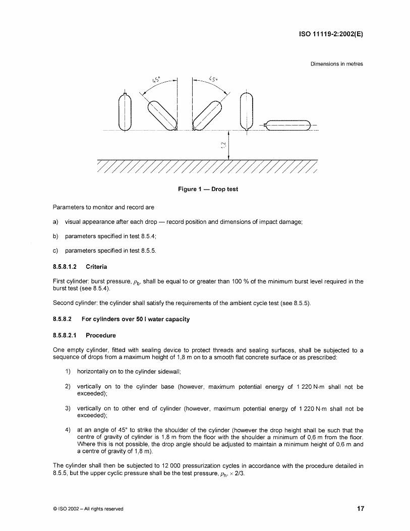
8.5.8.1.1 Procedure
Two cylinders shall be filled with water to 50 % capacity and fitted with a plug flush with the end of each cylinder.
The cylinders shall be dropped twice, in each of the five positions shown in Figure 1, from a height of 1,2 m on to a steel plate. The protective plate shall be sufficiently flat so that the difference in level between any two points on the surface is no more than 2 mm. It shall be replaced regularly and immediately, if damaged.
One cylinder is subjected to the burst test in 8.5.4.
The other cylinder is subjected to the pressure cycling test in 8.5.5.
a) visual appearance after each drop - record position and dimensions of impact damage;
b) parameters specified in test 8.5.4;
c) parameters specified in test 8.5.5.
8.5.8.1.2 Criteria
First cylinder: burst pressure, Pb' shall be equal to or greater than 100 % of the minimum burst level required in the burst test (see 8.5.4).
Second cylinder: the cylinder shall satisfy the requirements of the ambient cycle test (see 8.5.5).
8.5.8.2 For cylinders over 50 I water capacity
8.5.8.2.1 Procedure
One empty cylinder, fitted with sealing device to protect threads and sealing surfaces, shall be subjected to a sequence of drops from a maximum height of 1,8 m on to a smooth flat concrete surface or as prescribed:
1) horizontally on to the cylinder sidewall;
2) vertically on to the cylinder base (however, maximum potential energy of 1 220 N·m shall not be exceeded);
3) vertically on to other end of cylinder (however, maximum potential energy of 1 220 N·m shall not be exceeded);
4) at an angle of 45° to strike the shoulder of the cylinder (however the drop height shall be such that the centre of gravity of cylinder is 1,8 m from the floor with the shoulder a minimum of 0,6 m from the floor. Where this is not possible, the drop angle should be adjusted to maintain a minimum height of 0,6 m and a centre of gravity of 1,8 m).
The cylinder shall then be subjected to 12 000 pressurization cycles in accordance with the procedure detailed in 8.5.5, but the upper cyclic pressure shall be the test pressure, Ph' x 2/3.
a) visual appearance after each drop - record position and dimensions of impact damage;
b) parameters specified in test 8.5.5.
8.5.8.2.2 Criteria
The cylinders shall withstand 3000 pressurization cycles at the test pressure, Ph' x 2/3 without failure by burst or leakage. The test shall continue for a further 9 000 cycles, or until the cylinder fails by leakage, whichever is the sooner. In either case the cylinder shall be deemed to have passed the test. However should failure during this second part of the test be by burst, then the cylinder shall have failed the test.
8.5.9 High velocity impact (gunfire) test
8.5.9.1 Procedure
One cylinder shall be filled to the test pressure, Ph' x 2/3 with air or nitrogen.
The cylinder shall be positioned in such a way that the point of impact of the projectile shall be in the cylinder side wall at a nominal angle of 45 0 and such that the bullet would also exit through the cylinder side wall.
The bullet shall penetrate one wall of the cylinder at least. If this does not occur the energy of the bullet shall be increased until penetration is achieved.
Cylinders with diameter> 120 mm shall be impacted by a 7,62 mm (.3 calibre) armour piercing projectile (of length between 37 mm and 51 mm) with a nominal speed of about 850 m/s. The bullet shall be fired from a distance of not more than 45 m.
Cylinders with diameter of 120 mm and below, shall be impacted by a 5,6 mm armour piercing (or similar) bullet with a nominal speed of 850 m/s. The bullet shall be fired from a distance of not more than 45 m.
The dimensions of the entrance and exit openings shall be measured and recorded.
Parameters to monitor and record are
a) type of projectile;
b) initial pressure;
c) description of failure;
d) approximate size of the entrance and exit openings.
8.5.9.2 Criterion
The cylinder shall remain in one piece.
8.5.10 Fire resistance test
8.5.10.1 General
This test is mandatory if a pressure relief device is fitted to prevent failure in case of fire in service, and is optional for other uses.
One cylinder shall be fitted with a valve as follows:
a) with a valve intended for use (if known), or
b) with a valve fitted with bursting disc set to operate at between Ph and 1,15 Ph'
If the pressure relief valve in the test is that intended for use in service [Le. option a)], the specification of the valve shall be marked on the label (see 10.2)
The cylinders shall be charged with air or nitrogen or the gas intended for use to the test pressure, Ph' x 2/3.
A suitable fire can be created with either wood, gas or other hydrocarbon fuel. See ISO 11439 for details of the construction of the fire.
NOTE Other standards that contain directions to produce a suitable fire test are CGA C14 1992 and EN 3-1 1996.
The cylinder may be fire resistance tested in the vertical or horizontal position as follows.
Vertical: one cylinder shall be placed in an upright position (valve uppermost), with the lowest part of the cylinder approximately 0,1 m from the top of the firewood, in the case of a wood fire, or 0,1 m from the surface of the liquid in a fuel-based fire. The cylinder and valve should be exposed to total fire engulfment, but the relief device shall be shielded from direct flame impingement.
Horizontal: one cylinder shall be placed in a horizontal position with the lowest part of the cylinder approximately 0,1 m from the top of the firewood, in the case of a wood fire, or 0,1 m from the surface of the liquid in a fuel-based fire. The cylinder and valve shall be exposed to fire engulfment along its whole length, but the relief device shall be shielded from direct flame impingement.
The fire shall be capable of enveloping the entire length of the cylinder, when in the horizontal position, and producing a temperature ~ 590 °e, measured 25 mm below the cylinder within 2 min. The cylinder shall be exposed to the fires until it has completely vented.
After the test, the cylinder shall be rendered unserviceable.
Parameters to monitor and record are
a) type and characteristics of pressure relief device;
b) initial pressure;
c) location of leak;
d) temperature;
e) time.
8.5.10.3 Criteria
The cylinder shall not burst during a period of two minutes from the start of the fire test. It may vent through the pressure relief device or leak through the cylinder wall or other surfaces.
NOTE This test does not imply that only one pressure relief device assembly provides fire protection for the valve/prd system.
8.5.11 Salt water immersion test
8.5.11.1 General
This test is mandatory for all cylinders intended for underwater applications and is optional for other uses.
The cylinders shall be unpainted but otherwise finished as for the intended application.
The liner may be painted or protected from corrosion in any manner that is included in the design submission.
a) Immersion period
Two closed unpressurized cylinders shall be immersed for a period of between 1 hand 2 h in an aqueous solution containing 35 g/l of sodium chloride at a temperature not less than 20°C and be well aerated.
After 2 h the hydraulic pressure of the cylinder shall be increased to and maintained at the test pressure, Ph' x 2/3
for not less than 22 h. Pressure is then to be released.
b) Drying period
The pressurized cylinders shall then be taken out from seawater immersion and subjected to natural drying conditions in ambient atmosphere for not less than 22 h.
The hydraulic pressure of the cylinder shall be increased to and maintained at the test pressure, Ph, x 2/3 for not
less than 2 h. Pressure is then to be released.
Repeat the cycle consisting of these two periods a) and b) 45 times.
On completion of these tests one of the two cylinders shall be submitted to hydraulic pressure to burst, in accordance with 8.5.4 and the other cylinder shall be submitted to pressure cycling in accordance with test 8.5.5.
Parameters to monitor and record are
a) the temperature of the solution, at least once a day;
b) filling pressure;
c) duration of immersion;
d) parameters specified in test 8.5.4;
e) parameters specified in test 8.5.5.
8.5.11.3 Criteria
a) The burst pressure, Pb' shall be not less than the test pressure, Ph' x 1,67 of the composite cylinder design.
b) The second cylinder shall satisfy the criteria for the ambient cycle test, 8.5.5.
8.5.12 Torque test
8.5.12.1 Procedure
The body of the cylinder shall be held in such a manner as to prevent it rotating. The cylinder shall be fitted with a corresponding valve and tightened to 150 % of the maximum torque recommended in ISO 13341 for the relevant liner material, ISO 11439, or as recommended by the manufacturer where that standard does not apply.
The cylinder neck and threads shall show no significant deformation and shall remain within drawing and gauge tolerance.
8.5.13 High temperature creep test
8.5.13.1 Procedure
For a design life of up to 20 years, two cylinders shall be hydraulically pressurized to test pressure, Ph, and shall be maintained at this pressure for 1 000 h. For a design life equal to or greater than 20 years, the test shall run for 2 000 h. The test shall be conducted at a minimum temperature of 70 °C and a relative humidity of less than 50 %.
After this test, the cylinders shall be subjected to the burst test (see 8.5.4).
Parameters to monitor and record are
a) measurement of the water capacity before and after test;
b) temperature and relative humidity at least twice a day;
c) cylinder pressure at least twice a day;
d) burst pressure.
8.5.13.2 Criterion
Burst pressure, Pb' shall be equal to or greater than the test pressure, Ph, x 2.
8.S Failure of qualification tests
In the event of failure to meet test requirements, an investigation into the cause of failure and retesting shall be carried out in accordance with 9.5.
9 Batch inspection and testing
9.1 Liner
9.1.1 Each batch of liners shall be examined and dimensionally checked to ensure compliance with the design specification. The following inspections shall be carried out in accordance with the manufacturer's quality assurance procedures.
a) Visual inspection of surface finish.
b) Dimensions.
c) Neck folds. Interior folding in the liner neck area shall be prohibited. Smooth gathering of the material in the neck in which there are no sharp rooted folds shall be acceptable.
9.1.2 If finished cylinders are subjected to a hydraulic proof pressure test then 100 % of liners shall be subjected to hardness testing after heat treatment in accordance with either ISO 6506-1 or ISO 6508-1, and shall achieve the limits specified in 7.2.2.
If a finished cylinder is subjected to a hydraulic volumetric expansion test then 5 % of liners shall be subjected to hardness testing after heat treatment in accordance with either ISO 6506-1 or ISO 6508-1, and shall achieve the limits specified in 7.2.2.
9.1.3 One liner from every batch shall be tested to verify that the mechanical properties meet the minimum design requirements in accordance with the relevant standard for the liner material (see clause 2). For cylinders above 50 I water capacity a representative coupon for heat treatment may be substituted.
NOTE If quenching is part of the heat treatment, coupons need to be quenched from one side only. The length of the coupon needs to be greater than the diameter of the cylinder it represents.
9.1.4 A record of the tests carried out shall be kept at the premises of the cylinder manufacturer. Suitable forms of test certificate are shown in annex B.
9.1.5 In the event of failure to meet test requirements, an investigation into the cause of failure and re-testing shall be carried out in accordance with 9.2.
9.2 Failure of liner batch tests
9.2.1 If any of the test results are not satisfactory, and if the inspector is satisfied that this was due to an error when carrying out the test, a retest may be authorized using the same liner. Otherwise, at the discretion of the manufacturer, either:
a) the test in question shall be repeated on two specimens, one from the same liner or test ring as for the first test and another one from a liner or test ring from the same batch, and if both results are satisfactory the batch may be accepted or
b) the batch may be reheat treated (if appropriate) and retested in accordance with 9.1.2 and 9.1.3 and if the results are satisfactory the batch may be accepted.
9.2.2 Where heat treatment has been shown to be inadequate, liners may be subjected to retreatment, once only.
9.2.3 Where heat treatment furnace records show that artificial ageing has been inadequate, additional time at the ageing temperature shall be given.
9.2.4 If the test results, having allowed for retesting or reheat treatment, are not satisfactory, liners in the batch shall be rendered unserviceable.
9.3 Overwrap materials
Each batch of filament materials shall be subjected to an impregnated strand test in accordance with ASTM 02343 for glass and aramid and SACMA SRM 16R-94 or ASTM 04018 for carbon fibre, or identified equivalent standards accepted by the inspector. The strength of fibres shall be not less than specified in the documentation listed in 7.2.3.
9.4 Composite cylinder
9.4.1 The inspector shall certify that the design, manufacture, inspection and testing were carried out in accordance with this part of ISO 11119. An example form of certificate is shown in annex B.
9.4.2 Each batch of composite cylinders shall be examined and checked to ensure conformance to the design standard. The following inspections shall be carried out in accordance with the manufacturer's quality assurance procedures.
a) Visual inspection of external and internal surface finish.
b) Dimensions.
c) Markings.
d) Water capacity.
e) Weight.
f) Cleanliness.
g) Fibre tension (where applicable).
9.4.3 The internal and external surfaces of the finished cylinder shall be free from defects and residues from the manufacturing process (e.g. swarf, resin) which would adversely affect the safe working of the cylinders. See ISO 9809-1, ISO 9809-2 and ISO 7866 for guidance on possible defects in metallic liners.
9.4.4 Each completed cylinder shall be subjected to a hydraulic proof test (in accordance with 8.5.1) or a volumetric expansion test (in accordance with 8.5.2) at the design test pressure specified in 7.2.4.
9.4.5 One cylinder per batch of finished cylinders shall be subjected to a hydraulic pressure cycle test to test pressure, Ph, for unspecified gas service or maximum developed pressure at 65°C, Pmax' for dedicated gas service. The procedure shall be in accordance with 8.5.5, except that the test may be suspended, as appropriate to the design, either after 12 000 hydraulic cycles to test pressure or 24 000 cycles to maximum developed pressure, or after Nor Nd cycles where:
.7\/ = y x 250 cycles per year of design life
Nd = Y x 500 cycles per year of design life
y is the number of years of design life.
Cylinders with test pressure of 60 bar and above shall withstand N pressurization cycles to test pressure, Ph' (up to a maximum of 12 000 cycles), or Nd pressurization cycles to maximum developed pressure, Pmax (up to a maximum of 24000 cycles), without failure by burst or leakage. Cylinders with test pressure below 60 bar shall withstand 12 000 pressurization cycles to test pressure, Ph' without failure by burst or leakage.
9.4.6 One cylinder per batch of finished cylinders shall be subjected to a burst test in accordance with 8.5.4.
NOTE The cylinder subjected to the pressure cycle test (see 9.4.5) may be used for this test.
The burst pressure, Pb' shall be in accordance with the criteria for the cylinder burst test specified in 8.5.4.
9.5 Failure of qualification or batch tests
9.5.1 In the event of failure to meet test requirements either during a production run (batch test) or when design qualification tests do not give satisfactory results an investigation into the cause of failure and retesting shall be carried out as follows.
9.5.2 If there is evidence of a fault in carrying out a test, or an error of measurement a second test shall be performed on the same cylinder, if possible. If this is not possible, then a second test shall be performed on a cylinder selected at random from the batch. If the results of this test are satisfactory, the first test shall be ignored.
9.5.3 If the test has been carried out in a satisfactory manner either
a) the cause of failure shall be identified and the procedure detailed in 9.5.4 or 9.5.5 shall be followed or
9.5.4 If the cause of failure is identified, the defective cylinders may be reclaimed by an approved method or shall be rejected. The reclaimed cylinders shall be considered a separate batch from the original satisfactory cylinders. The failed test shall be repeated with the quantities required in 8.5.4 or 8.5.5 (as applicable) for both batches. For failures found during 100 % batch testing only the repaired cylinders need to be retested. If one or more tests prove even partially unsatisfactory, all the cylinders of the batch(es) covered by the tests shall be rejected.
9.5.5 Alternatively the cause of failure may be investigated and if this is identified the defective cylinders in the batch shall be removed from the batch and the failed test shall be repeated with the quantities required in 8.5.4 or 8.5.5 (as applicable) for the original batch.
9.5.6 If a batch fails the second series of tests, the batch of cylinders shall be scrapped and rendered unserviceable for holding gas under pressure. The manufacturer shall ensure that the cylinder does not enter service.
10 Cylinder marking
10.1 General
Each finished composite cylinder which satisfies the requirement of this part of ISO 11119 shall be permanently and legibly marked in accordance with ISO 13769 and ISO 7225.
10.2 Additional marking
10.2.1 The following information shall be permanently marked on the cylinder as a label embedded in the resin.
a) "WARNING - THIS CYLINDER MUST BE FILLED ONLY WITH «Named Gas(es»>" where a cylinder is to be used for dedicated gas service;
b) "WARNING - THIS CYLINDER MUST BE USED WITH A «Named» PRESSURE RELIEF DEVICE" where a cylinder is approved with a specific pressure relief device (see 8.5.10);
c) "Maximum torque «{manufacturer's recommended torque»>" where fitting torque does not correspond to the values given in ISO 13341.
10.2.2 Additional markings (e.g. retest dates in accordance with national legislation, customer names etc.) may be contained on the main label or applied as a secondary label securely affixed to the cylinder side wall.
10.2.3 All labels shall be clearly marked with letters of not less than 3 mm high.
Design approval certificate - composite cylinders with load-bearing metal liners
Issued by .................................................................. (Relevant authority) ............................................. on the basis of applying ISO 11119-2:2002 Gas cylinders of composite construction - Specification and test methods - Part 2: Fully wrapped fibre reinforced composite gas cylinders with load-sharing meta/liners.
Approval No. .................................................................................... Date .................................................................................... .
Cylinder description .................................. (Family of cylinders which has received type approva~ .............................................. .
Manufacturer's Drawing No ............................................................................................................................................................. .
Design life ............................... Underwater ................... Special torque ....................... Pressure relief device ......................... ..
Manufacturer or agent.................................... (Name and address of manufacturer or its agent) ............................................... ..
Type of approval mark .................................................................................................................................................................... .
Details of the results of the examination of the design for design approval are detailed in Qualification Test Report ..................... .
All information may be obtained from .......................................... (Name and address of the approving body) ............................. ..
Date ............................................................................................ Place ......................................................................................... .
NOTE Items in parentheses below refer to the clauses of ISO 11119-2:2002.
Each liner was produced by an approved process in accordance with 6.1 heat treated by an appropriate method and checked for hardness. The results of the mechanical tests have been found satisfactory (see 9.1.3).
Overwrap was applied by winding under controlled tension.
Filament Glass Carbon Aramid
designated
supplied by ___________________________________ _
manufactured by _________________________________ _
Identified by package number and cured after wrapping to the manufacturer's standard.
Filaments strand strength and reinforcement were verified and found satisfactory.
Each cylinder was subjected to an autofrettage pressure of ___ _ bar for approximately
(if appropriate)
Each cylinder was subjected to a hydraulic proof pressure test (8.5.1) or volumetric expansion test (8.5.2) at the test pressure stated above.
The results of the batch pressure cycle and burst tests were satisfactory.
Each cylinder has been marked as required by the ISO 11119-2 (clause 10).
WE HEREBY CERTIFY that each of the above cylinders meet in full the requirements of ISO 11119-2.
Forand on behaWofthemanufacturer __________________________ ~
For and on behalf of the Approved I nspection Body
[1] ISO 6892:1998, Metallic materials - Tensile testing at ambient temperature
[2] ISO 7438:1985, Metallic materials - Bend test
[3] ISO 10156:1996, Gases and gas mixtures - Determination of fire potential and oxidizing ability for the selection of cylinder valve outlets
[4] ISO 11114-2, Transporiable gas cylinders - Compatibility of cylinder and valve materials with gas contents - Pari 2: Non-metallic materials
[5] ISO 11623:2002, Transporiable gas cylinders - Periodic inspection and testing of composite gas cylinders
[6] EN 3-1 : 1996, Poriable fire extinguishers - Pari 1: Description, duration of operation, class A and 8 fire test
[7] EN 144-1, Respiratory protective devices - Gas cylinder valves - Pari 1: Thread connections for inseri connector
[8] EN 962, Transporiable gas cylinders - Valve protection caps and valve guards for industrial and medical gas cylinders - Design, construction and tests
[9] ASTM D 2290, Standard Test Method for Apparent Hoop Tensile Strength of Plastic or Reinforced Plastic Pipe by Split Disk Method
[10] ASTM D 2291, Standard Practice for Fabrication of Ring Test Specimens for Glass-Resin Composites
[11] ASTM D 2344, Standard Test Method for Shori-8eam Strength of Polymer Matrix Composite Materials and Their Laminates .
[12] CGA Pamphlet C-6.2: Guidelines for Visual Inspection and Re-Qualification of Fiber Reinforced High Pressure Cylinders
[13] CGA C14: 1992, Procedures for testing of DOT cylinder pressure relief device systems


![is.15575.2.2005 [IEC 61672-2 (2003)] [law.resource.org]](https://static.documents.pub/doc/80x56/577cc9b81a28aba711a46e60/is1557522005-iec-61672-2-2003-lawresourceorg.jpg)


