Inner Range T4000 Security Communicator 1 T4000 Security Communicator by Inner Range P/N: 998530 / 998530NZ Installation & Operation Manual. Rev: 1.2 Inner Range Pty. Ltd. www.innerrange.com Ph: +61 3 9780 4300
Transcript
Inner Range T4000 Security Communicator 1
T4000 Security Communicator by Inner Range
P/N: 998530 / 998530NZ
Installation & Operation Manual. Rev: 1.2
Inner Range Pty. Ltd. www.innerrange.com Ph: +61 3 9780 4300
Inner Range T4000 Security Communicator 2
INTRODUCTION The Inner Range T4000 security communicator provides two-way communication between a monitored site and the Monitoring Centre to allow highly secure polled alarm communications. The T4000 is capable of interfacing with alarm systems using an RS-232 serial connection or dialer capture of contact-ID signals.
T4000 Features
• Simple Plug and Play installation. • Ultra-fast 3G Dual-SIM polled communications paths. • 10/100 Mbps Ethernet Port for high-speed polling and encrypted Internet alarm transmissions • Configurable Bi-directional polling from 10 sec to 5 min meets Australian standard AS2201.5 • Secure 128Bit AES Encrypted data transmission. • Dialer Capture port to receive communications from any alarm panel equipped with a dialer and
programmed to report Contact-ID. • High level Integration with Inner Range Integriti, Infiniti and Concept 3/4000 systems. See “Alarm
Panel Connection Guide” later in this document for details. • Relay output for control of external devices. e.g. Remotely Arm/Disarm connected alarm panel.* • General purpose security input. e.g. Cabinet tamper if installed in separate enclosure. • Application that allows the end user to control the alarm system. e.g. Arm/disarm, aux control &
automation.* Available on Google Play and web: https://skycommand.innerrange.com • Over-the-air upload/download to compatible alarm systems using modem dial up and serial pass-
through methods. • Remote Firmware upgrade capability. • Contact-ID, IRFast and IRFast+text formats. • Compact and versatile form factor. • Easy to read functional LED status display. • 12-24V DC Supply Voltage. • Battery backup capability (Battery purchased separately).
*Requires external wiring. See wiring diagrams later in this document.
Parts List Main Parts: Accessory Kit contents: T4000 Security Communicator. 4 x Metal PCB Mounting Clip. M3. Antenna 3.5dBi with magnetic base & 2m cable. 4 x M3 x 35mm pan head screw. Installation manual (This document). 1 x Self-adhesive Hook and Loop tape. 80 x 50mm Accessory Kit. See list opposite. 3 x 2-way 3.5mm Screw Terminal connector. 2 x 3-way 3.5mm Screw Terminal connector. 1 x Dialer interface cable. 611 socket to RJ12 plug. Optional Accessories: Accessory Part Number: 18V DC 1A Plug-pack & Battery cables. 999065 12V 7AH Sealed Lead Acid Battery. e.g. CSD P/N: CSD-1200. Atlas Gentech SKU: 50204 Concept/Integriti Port 0 interface cable. 996795 See page 9 for details. Concept/Integriti UART interface cable. 996796 See page 9 for details. Small Metal Enclosure with Tamper Switch 995200XS High-gain Antennae: 6.5dBi. 5m cable. 4.5dBi. 10m cable. 9dBi 6-element Directional Yagi. 10m cable.
994093. 994094. 994097.
Inner Range T4000 Security Communicator 3
INSTALLATION
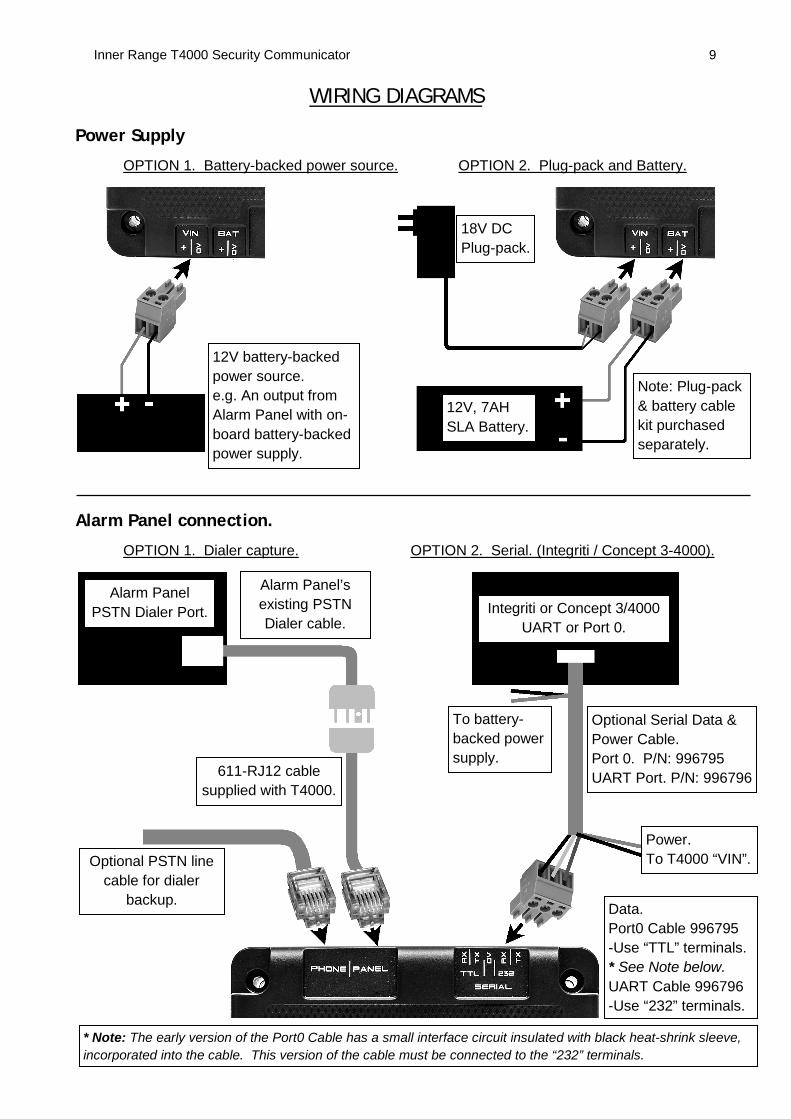
Power Supply Options The T4000 has connections for a DC Power Supply input and an optional 12V Sealed Lead-Acid (SLA) Battery. These connections are labelled “VIN” and “BAT” respectively and allow two power supply options to be supported:
1. External Power Supply. Connect 12 to 24V DC from a battery-backed power supply to “VIN”. e.g. A 13.75V output from an Alarm Panel with on-board battery-backed power supply, or a separate battery-backed power supply. In this case, the BAT connection is not used. Ensure that the T4000 power requirements will not cause the power supply’s current limit to be exceeded. Remember to allow for the current required by other devices that may be powered from the same supply. See “Specifications” on the last page of this document for details.
2. Plug-pack & Battery. Connect 14 - 24V DC to “VIN” and connect a 12V 7AH SLA Battery to “BAT”. e.g. Using the optional T4000 18V DC plug pack & battery cable kit. (P/N: 999065)
Refer to the wiring diagrams and specifications later in this document for more details.
Installation Procedure
1. Place the T4000 Security Communicator and the supplied antenna in the location where you intend it to be installed. Apply power and screw the antenna cable connector to the threaded antenna socket on the T4000. When connecting the antenna to the T4000 ensure that the connector is finger tight and has not been over-tightened, the antenna has not been cut or modified in any way and the cable is free of any kinks or sharp bends.
2. Before you mount the T4000 you will need to test the signal strength in your chosen
location. If the signal strength is poor you will need to install a high gain antenna or find a more suitable location for the T4000 in order to obtain greater signal strength.
3. The ‘GSM REG’ LED indicates 3G cellular network connectivity. When the ‘GSM REG’
LED is On solid the colour of the LED will indicate the current level of GSM signal strength. The T4000’s GSM modem should take less than 1 minute to register onto the 3G cellular network.
Green = Good signal strength. Yellow = Acceptable strength. Red = Poor signal strength.
4. The ‘GSM REG’ LED will also indicate whether the modem is operational or experiencing any issues.
Green flashing = Currently registering on the GSM network. On = Has GSM registration. Red flashing = Faulty modem.
Inner Range T4000 Security Communicator 4
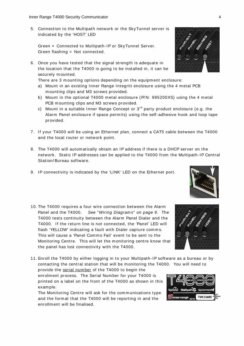
5. Connection to the Multipath network or the SkyTunnel server is indicated by the ‘HOST’ LED Green = Connected to Multipath-IP or SkyTunnel Server.
Green flashing = Not connected.
6. Once you have tested that the signal strength is adequate in the location that the T4000 is going to be installed in, it can be securely mounted. There are 3 mounting options depending on the equipment enclosure: a) Mount in an existing Inner Range Integriti enclosure using the 4 metal PCB
mounting clips and M3 screws provided. b) Mount in the optional T4000 metal enclosure (P/N: 995200XS) using the 4 metal
PCB mounting clips and M3 screws provided. c) Mount in a suitable Inner Range Concept or 3rd party product enclosure (e.g. the
Alarm Panel enclosure if space permits) using the self-adhesive hook and loop tape provided.
7. If your T4000 will be using an Ethernet plan, connect a CAT5 cable between the T4000 and the local router or network point.
8. The T4000 will automatically obtain an IP address if there is a DHCP server on the network. Static IP addresses can be applied to the T4000 from the Multipath-IP Central Station/Bureau software.
9. IP connectivity is indicated by the ‘LINK’ LED on the Ethernet port.
10. The T4000 requires a four wire connection between the Alarm
Panel and the T4000. See “Wiring Diagrams” on page 9. The T4000 tests continuity between the Alarm Panel Dialer and the T4000. If the return line is not connected, the ‘Panel’ LED will flash ‘YELLOW’ indicating a fault with Dialer capture comms. This will cause a ‘Panel Comms Fail’ event to be sent to the Monitoring Centre. This will let the monitoring centre know that the panel has lost connectivity with the T4000.
11. Enroll the T4000 by either logging in to your Multipath-IP software as a bureau or by contacting the central station that will be monitoring the T4000. You will need to provide the serial number of the T4000 to begin the enrolment process. The Serial Number for your T4000 is printed on a label on the front of the T4000 as shown in this example. The Monitoring Centre will ask for the communications type and the format that the T4000 will be reporting in and the enrollment will be finalised.
Inner Range T4000 Security Communicator 5
12. Test the GSM signal strength on both SIM cards.
13. Test alarm panel alarm event delivery via dialer capture or serial communications and the panel disconnection alarm.
LED Status Indicators The T4000 has seven functional status LED’s to quickly identify the current power and connection status.
LED Colour Behavior
PWR/BAT Green Flashing = Problem with Battery or Input power. Off = No power. On = Power OK.
Panel
Green = Serial comms mode. Yellow = Dialler Capture mode. Red = Upload/download in progress.
On = External Panel connection OK. Flashing = External Panel Disconnected. Red flashing = Panel upload/download in progress.
GSM REG Green = Good signal strength. Yellow = Acceptable strength. Red = Poor signal strength.
RED flashing = Faulty modem. Green flashing = Registering on GSM network. On = Has GSM registration.
HOST Green On = Connected to Multipath-IP or SkyTunnel Server Host. Flashing = Not connected.
Alarms Yellow On = Alarms buffered. Off = No alarms buffered.
GSM Green On = GSM modem is turned on.
SIM 1/2 Green On = Currently using SIM 1. Flashing = Currently using SIM 2.
Inner Range T4000 Security Communicator 6
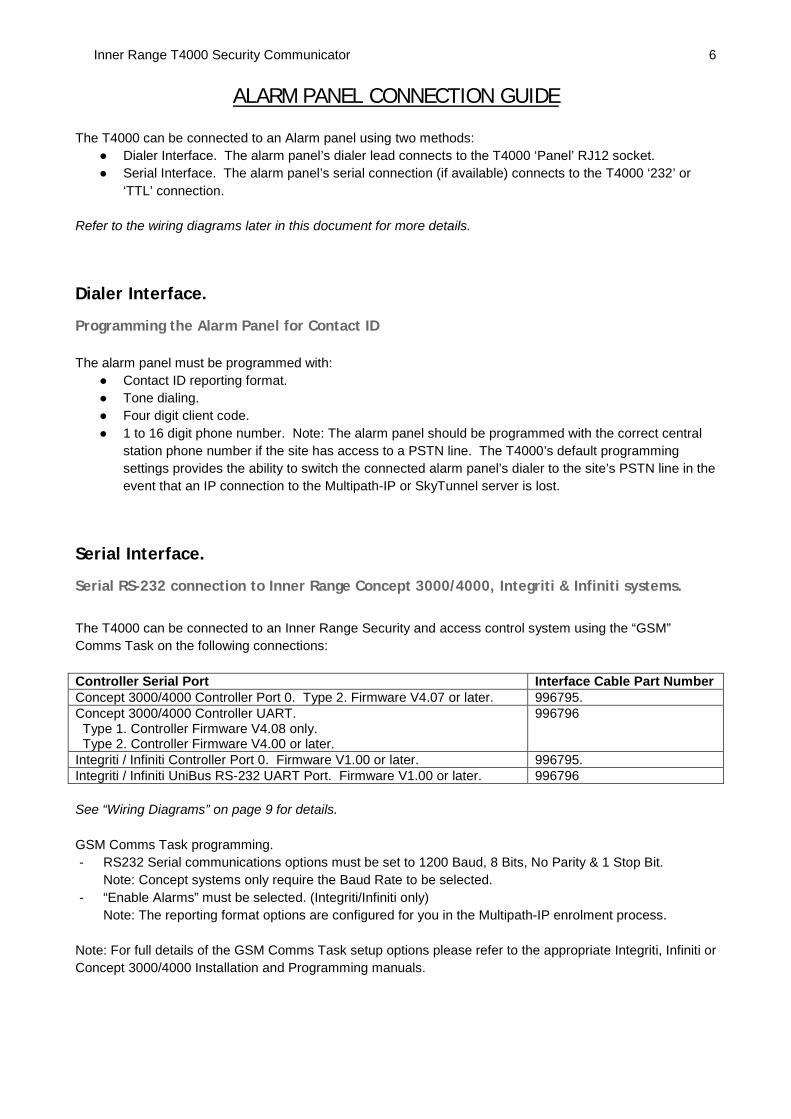
ALARM PANEL CONNECTION GUIDE The T4000 can be connected to an Alarm panel using two methods:
● Dialer Interface. The alarm panel’s dialer lead connects to the T4000 ‘Panel’ RJ12 socket. ● Serial Interface. The alarm panel’s serial connection (if available) connects to the T4000 ‘232’ or
‘TTL’ connection.
Refer to the wiring diagrams later in this document for more details.
Dialer Interface.
Programming the Alarm Panel for Contact ID The alarm panel must be programmed with:
● Contact ID reporting format. ● Tone dialing. ● Four digit client code. ● 1 to 16 digit phone number. Note: The alarm panel should be programmed with the correct central
station phone number if the site has access to a PSTN line. The T4000’s default programming settings provides the ability to switch the connected alarm panel’s dialer to the site’s PSTN line in the event that an IP connection to the Multipath-IP or SkyTunnel server is lost.
Serial Interface.
Serial RS-232 connection to Inner Range Concept 3000/4000, Integriti & Infiniti systems. The T4000 can be connected to an Inner Range Security and access control system using the “GSM” Comms Task on the following connections: Controller Serial Port Interface Cable Part Number Concept 3000/4000 Controller Port 0. Type 2. Firmware V4.07 or later. 996795. Concept 3000/4000 Controller UART. Type 1. Controller Firmware V4.08 only. Type 2. Controller Firmware V4.00 or later.
996796
Integriti / Infiniti Controller Port 0. Firmware V1.00 or later. 996795. Integriti / Infiniti UniBus RS-232 UART Port. Firmware V1.00 or later. 996796 See “Wiring Diagrams” on page 9 for details. GSM Comms Task programming. - RS232 Serial communications options must be set to 1200 Baud, 8 Bits, No Parity & 1 Stop Bit.
Note: Concept systems only require the Baud Rate to be selected. - “Enable Alarms” must be selected. (Integriti/Infiniti only)
Note: The reporting format options are configured for you in the Multipath-IP enrolment process. Note: For full details of the GSM Comms Task setup options please refer to the appropriate Integriti, Infiniti or Concept 3000/4000 Installation and Programming manuals.
Inner Range T4000 Security Communicator 7
T4000 MAINTENANCE.
Firmware updating the T4000 It is recommended that the T4000 is updated to the latest firmware version. The T4000 firmware update is performed ‘over the air’ using the Multipath-IP client software. This can be performed by the Central Station operator or Bureau technician. Please refer to the Multipath-IP client user manual for information on remote firmware updates.
Rebooting the T4000. The T4000 can be soft reset by two methods:
● By momentarily pressing the reset button on the unit with a paper clip or pin.
● By sending a reset command from the software by clicking on the ‘hard reset’ icon. See screen image below.
The T4000 can be also be reset by removing power from the unit, waiting 10 seconds and then re- applying the power and battery connections.
Defaulting the T4000. The T4000 can be set back to factory default by using the following methods:
● by depressing the reset button on the unit with a paper clip or pin and holding it depressed for more than 10 seconds. See picture above for location of reset button.
● by un-enrolling the T4000 using the Multipath software. Note: If the T4000 is to be moved to a new Central Station, the T4000 must be unenrolled and cancelled from the originating Central Station.
Reset button
Inner Range T4000 Security Communicator 8
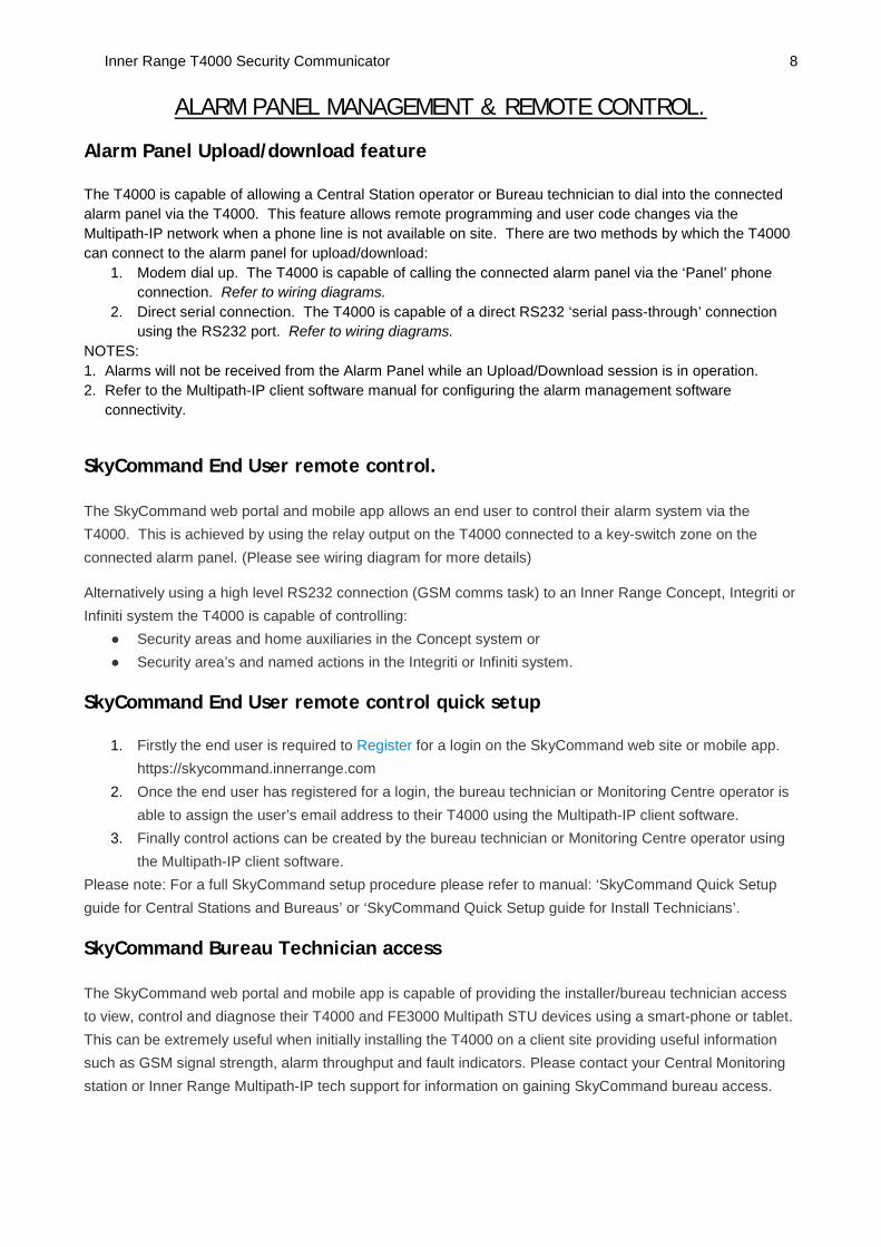
ALARM PANEL MANAGEMENT & REMOTE CONTROL.
Alarm Panel Upload/download feature The T4000 is capable of allowing a Central Station operator or Bureau technician to dial into the connected alarm panel via the T4000. This feature allows remote programming and user code changes via the Multipath-IP network when a phone line is not available on site. There are two methods by which the T4000 can connect to the alarm panel for upload/download:
1. Modem dial up. The T4000 is capable of calling the connected alarm panel via the ‘Panel’ phone connection. Refer to wiring diagrams.
2. Direct serial connection. The T4000 is capable of a direct RS232 ‘serial pass-through’ connection using the RS232 port. Refer to wiring diagrams.
NOTES: 1. Alarms will not be received from the Alarm Panel while an Upload/Download session is in operation. 2. Refer to the Multipath-IP client software manual for configuring the alarm management software
connectivity.
SkyCommand End User remote control. The SkyCommand web portal and mobile app allows an end user to control their alarm system via the T4000. This is achieved by using the relay output on the T4000 connected to a key-switch zone on the connected alarm panel. (Please see wiring diagram for more details)
Alternatively using a high level RS232 connection (GSM comms task) to an Inner Range Concept, Integriti or Infiniti system the T4000 is capable of controlling:
● Security areas and home auxiliaries in the Concept system or ● Security area’s and named actions in the Integriti or Infiniti system.
SkyCommand End User remote control quick setup
1. Firstly the end user is required to Register for a login on the SkyCommand web site or mobile app. https://skycommand.innerrange.com
2. Once the end user has registered for a login, the bureau technician or Monitoring Centre operator is able to assign the user’s email address to their T4000 using the Multipath-IP client software.
3. Finally control actions can be created by the bureau technician or Monitoring Centre operator using the Multipath-IP client software.
Please note: For a full SkyCommand setup procedure please refer to manual: ‘SkyCommand Quick Setup guide for Central Stations and Bureaus’ or ‘SkyCommand Quick Setup guide for Install Technicians’.
SkyCommand Bureau Technician access The SkyCommand web portal and mobile app is capable of providing the installer/bureau technician access to view, control and diagnose their T4000 and FE3000 Multipath STU devices using a smart-phone or tablet. This can be extremely useful when initially installing the T4000 on a client site providing useful information such as GSM signal strength, alarm throughput and fault indicators. Please contact your Central Monitoring station or Inner Range Multipath-IP tech support for information on gaining SkyCommand bureau access.
* Note: The early version of the Port0 Cable has a small interface circuit insulated with black heat-shrink sleeve, incorporated into the cable. This version of the cable must be connected to the “232” terminals.
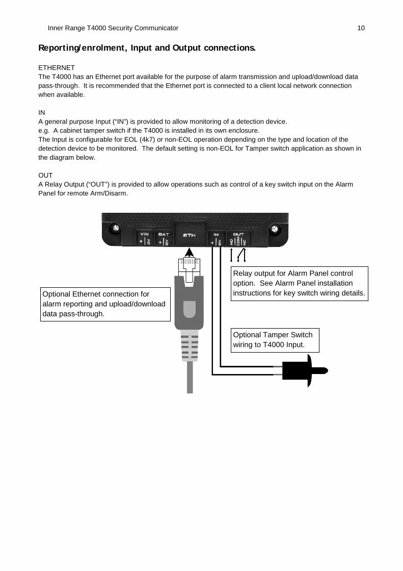
Inner Range T4000 Security Communicator 10 Reporting/enrolment, Input and Output connections. ETHERNET The T4000 has an Ethernet port available for the purpose of alarm transmission and upload/download data pass-through. It is recommended that the Ethernet port is connected to a client local network connection when available. IN A general purpose Input (“IN”) is provided to allow monitoring of a detection device. e.g. A cabinet tamper switch if the T4000 is installed in its own enclosure. The Input is configurable for EOL (4k7) or non-EOL operation depending on the type and location of the detection device to be monitored. The default setting is non-EOL for Tamper switch application as shown in the diagram below. OUT A Relay Output (“OUT”) is provided to allow operations such as control of a key switch input on the Alarm Panel for remote Arm/Disarm.
Relay output for Alarm Panel control option. See Alarm Panel installation instructions for key switch wiring details.
Optional Tamper Switch wiring to T4000 Input.
Optional Ethernet connection for alarm reporting and upload/download data pass-through.
Inner Range T4000 Security Communicator 11
Multipath-IP Data Plans The T4000 communications poll rate and supervision period is dependent on the transmission plan selected by the Central Monitoring station operator or Bureau technician using the Multipath-IP client software.
AS2201.5 Alarm Transmission plans
AS2201.5 Transmission Supervision Period
Ethernet Only
Single SIM
Single SIM + Ethernet
Dual SIM
Dual SIM + Ethernet
Class 2. 12 Hour TC2S12H
Class 2. 1 Hour E2 TC2S TC2SE TC2D TC2DE
Class 3 120 Seconds
E3 TC3S TC3SE TC3D TC3DE
Class 4 60 Seconds
TC4SE TC4DE
Class 5 20 Seconds
TC5SE TC5DE
Inner Range T4000 Security Communicator 12
Specifications
Enclosure Type: ABS plastic. Dimensions: 101mm x 98mm x 35mm. Shipping Size / Weight (gross): 190g Installation environment: 0°C-50°C @ 15%-90% relative humidity (non-condensing) Power Source (To “VIN”) - If Battery connected to T4000: - No Battery connected to T4000:
Recommended Battery: 12 Volt SLA (gel) type, 7 Amp-Hour. Current consumption @ 18V DC: 90mA (Idle) + 30mA (GSM Online). (Not including Battery
charging) Battery Charger output: 13.75V DC. Max Battery charger output current: 500mA average. Typical Battery Backup Time: 72 hours (If Battery is powering T4000 only) Minimum Battery Backup time: 48 hours (If Battery is powering T4000 only) Minimum operating voltage: 8V DC Low battery sense voltage (typical): 11.0V Fuse: PTC protection + onboard fuse (non-replaceable) Zone input: 1. Software configurable (EOL or Non-EOL)
Default setting is non-EOL for Tamper switch application. Relay output (“OUT”) contact rating: 2 Amps 30v DC Indicator LED’s: 9. Alarm formats: Contact ID, IRFast, IRFast + Text Max PABX line voltage: 65V RMS Max PABX current: 30mA PABX output level: -10dBm Max RF Power: 2 Watts Disclaimer:
1. The manufacturer and/or its agents take no responsibility for any damage, financial loss or injury caused to any equipment, property or persons resulting from the correct or incorrect use of the system or it’s peripherals. The purchaser assumes all responsibility in the use of the system and its peripherals.
2. While every effort has been made to ensure the accuracy of this manual, the manufacturer assumes no responsibility or liability for any errors or omissions. Due to ongoing development, product specifications and the contents of this manual are subject to change without notice.