18
By Matthew A. Erickson KK5DR Copyright © 2003 Revised updated edition. “Written for ALPHA 76 lovers, by an ALPHA 76 lover.“ 1

By Matthew A. Erickson KK5DR
Copyright © 2003 Revised updated edition.
“Written for ALPHA 76 lovers, by an ALPHA 76 lover.“
1

ALPHA 76 series description
The pictures on the first page show in descending order are the 76(standard), 76A(all versions), 374A, and 78. In 1979 the ALPHA 76 was designed, closely following the designs of its predecessor, the 374,(the 374 was not the same as the later 374A) which had a band-pass, "no-tune" feature. The 76, on the other hand were built without the “no-tune” feature, my guess is that this was done to make them more economical & profitable. The 76 originally sold for about $1,795 when they hit the amateur market in 1980, it was known as the 76 “standard” with two 8874 tubes, and a 76PA with three tubes, and a 76CA with three tubes and a “hypersil” transformer & vacuum relay T/R system. In 1982 the 76A was produced, which had a few changes to it, most visible are the twin meters on the front panel. The cabinet style & color were also changed, from the old tan & brown of the 76 Standard, to a dark charcoal front panel & a gray cabinet. In 1988 production ended on the 76 series, but close to the end, ETO changed the front panel paint, to a hard black enamel. The 76 Standard had a “bolt-together” cabinet with separate front, sides, and top, a one-piece back and bottom. The 76A has a one-piece top & sides, also bottom, back, and front one-piece. The front is a sub type with an overlay panel on it. All made of heavy aluminum plate. The 76 Standard has a single multi function meter on the front panel. The units that had the CW/SSB low/high voltage switch on the front, have what is know as “option L”, most units found now days have it. The 76A has two meters on the front, with one dedicated to plate current reading, and the other for RF output, HV, and grid current. The high/low voltage switch is now part of the standby/operate switch, labeled as "CW/SSB." The variants of the 76 are the "P" for "PA", which is the high power ham version, and the "C" for "CA" which is the "commercial" version in the series, extra heavy duty. The 76, 76A, 374A, & 78 are all in the same family of amps, sharing much of the same circuits and same basic design. Your exact version can be found on the sticker on the back panel of the unit. The unit serial number can also be found there.
How many? The total of 225 units for the 76 standard were built in all flavors such as the "standard", the "P", and "C" versions A total of 1659 units of the 76A in all variants were produced. The 374A (a variation of the 76 series) were produced in the number of 365. Lastly, the 78 variants were built in the number of 900 units. If you check the Alpha web site, in the "Legacy amplifier" section, you can find a list of serial number sequences as well as production dates. You can pin-point your units age there.
2

76A “Nasty paint”
Some “bright” person at ETO, had a cool idea, to paint the front panel of the 76A with a tough wear resistant paint, a good concept. One problem, the paint never cures/dries, it remains tacky and soft forever. It also scratches and wears easily, A good concept, but in reality it didn’t work. To fix this problem you can buy a new front panel for about $150 from ALPHA, or repaint it and have it professionally silk-screened for about $250. I did the painting and lettering myself for about $20, but costing about 80 hours of tedious hand work. The choice is up to you, if I did it over again, I think I’d buy a new panel. If you have a unit with hard black paint, count your blessings.
8874 tubes Let me talk about the tubes for a bit. The EIMAC 8874, also known as the 3CX400A7, is a high gain, metal/ceramic, 11 pin, power triode, with gold plated internal parts & indirectly heated, oxide coated cathode and 400 watts of plate dissipation, that is in the family of tubes with the 8873, & 8875. They are all electrically identical the only differences are the way in which they are cooled. If the tube is cathode driven, a resistor T-network is necessary, to pad the input, but if the tubes were driven directly, it takes only about 1 watt per tube, to get full output. THIS TUBE HAS ALLOT OF GAIN! An amp equipped with three of these tubes has 1200 watts of plate dissipation, and can safely key down 1200 watts AM, FM, & CW, if the power supply is up to the task. EIMAC states that the total plate dissipation can be exceeded on SSB only, by a factor of 1.5, or 1800 watts P.E.P. output on SSB. I personally have seen 2KW+ out of my 76A when I over drove it accidentally, for a few moments. There were no ill effects, no blown fuses, no tripped breakers, the amp just kept going. My old 76 Standard was able to develop up to 1800 watts of output on 40meters when in the SSB B+ position, but this ran it right to the very limits of grid & plate current ratings, I would not advise doing this, not just because it would be illegal to transmit at this output on the air, but the potential for damaging the tubes it too great. Of course I tested mine only into a dummy load… It is still good procedure to never run an amp over it’s max plate dissipation rating. This also gives the best IMD (Inter-Modulation-Distortion) levels too. The 8874 tubes are abit pricey now days, if you buy new ones, but SVETLANA is now making them in competition with EIMAC, maybe the prices will come down soon. "Pulled" used tubes can be a cheap replacement, but you never now how long they were in service, or what condition they are in when you receive them. When handling them, try not to touch the metal part, it’s silver plated, and fingers will leave marks and stains. A plastic glove is a good idea. NEVER, EVER scratch or brush the ceramic part of the tube, it is beryllium oxide, and is highly TOXIC to humans or animals, best not to touch it bare-handed either.
3

The shine can be restored to the tube, by pulling it out of the amp and soaking it in a solution of 50/50 white ammonia & 409 cleaner, rinsed off with water, then dried with a hair dryer or set out in the sun to dry thoroughly. Another point of caution in the handling of the tube: They are very delicate internally and a mild drop or shock can open up the filament or cause it to short to the grid. Some parts inside the tube are not more than a few thousandths of an inch apart, so, be careful with these jewels. Used tubes become very fragile due to the elements getting more brittle from the heating and cooling. I have seen tubes damaged by a drop of only 1" when moving the amp. The tube shorted internally, and had to be replaced. Be very careful even when moving the amp. Handle the tubes with extreme care when removing them from the amp. If you plan to ship the amp, it is absolutely mandatory to remove the tubes, and transformer, and pack them separately. Cushioning of the tubes should be taken to the extreme. What amazes me about the 8874, is the amount of power it puts out, for it’s tiny size. It’s easier to believe that a 3-400Z puts out the same power. But if you think about it, minus the glass envelope, the actual metal parts of the tube are about the same size as the 8874, so, it makes more sense then. The 8874’s are the heart of the ALPHA 76 amps, and should be treated with care. Never over drive them in a chronic, on-going basis. Use the ALC feedback system to prevent this from happening. Ray Heaton, long time employee of ETO ALPHA, in the amateur amp section, was quoted as saying; “Keep the grid current as low as possible, and the tubes will last a very, very long time.” I did abit of calculations to find out how long. The 8874 is a 24,000 hr. average filament on-time tube, using this, the average ham operating it for 12 hrs per week could see 38.5 yrs. of service out of it. In the unlikely event you operate it, all your waking hours, 60hrs. per week, you could still get 7.6 yrs. service from it. WOW! Of course this does not account for the unforeseen failure due to, parasitics, voltage & current surges. Failures caused by user abuse, over-drive, poor tuning, high SWR, etc., etc, account for 90% of all tube failures. For the most part these tubes are very good units, well behaved, high output, small, & forgiving. They are also very precisely built, no need for matched sets, metal/ceramic tubes of a given type, are basically all the same. However, I would not mix brands such as EIMAC & Svetlana. Trying to get tubes with date codes within two years of each other would be better too. It is suggested that you not mix old tubes with new ones, as the new units will have a higher gain level then the used ones. Yes, the 8874 does have rather delicate grid, and it can be damaged by chronic overdrive, or high SWR, or poor tuning. But, it is a well behaved tube, and gives super gain at relatively low plate voltages. It also can be used up into the 450mhz range, and if the 3CX400U7 coaxial socket tube is used, it can go well into the GHZ range.
8874 to 3CX800A7 conversion
4

DON’T ATTEMPT THIS MOD. UNLESS YOUR EXPERIENCED IN AMP BUILDING, & ELECTRONICS! A possible alternative to the 8874’s in your ALPHA 76, is the conversion to the currently popular 3CX800A7, that are used in the newer ALPHA’s and other amps. The 800 is basically the same as the 8874 except the plate dissipation is 800 watts, and the filament is 13.5Vac@ 1.5A. The tube will fit into the same 11pin socket too. The modification of the 76 will require a new filament transformer capable of 3A. Radio Shack 12.6Vac, 3A. transformer works fine. No center tap is needed on the filament transformer, HV insulation is not needed due to the tubes being indirectly heated cathode type. Wire the primary of the transformer into the primary side of the main power transformer. Then wire the secondary of the new filament transformer the same way the original filament was wired. Remove the yellow wire from the original power transformer modular plug and hook it to the new filament transformer, simple as that. But, it might not be as simple as you think, to find a space to mount the new transformer, the 76 is abit limited for extra room to mount a part that usually is about 3-4 inches square and about 3 inches tall. If you have a two tube 76, this mod. may be difficult to fit the new tubes, but a three tube unit is a good candidate. Place a plate cover over the empty tube socket in the middle, leaving the two holes that are the farthest apart. The new tubes are larger in diameter and will require a new set of chimneys these can be bought from ALPHA. Remove the extra plate connector from the plate choke. This is pretty much all there is to the mod. the amp will tune up differently, but should run the same or more power output.! A very expensive option it to put a “New” ALPHA power transformer into the 76. The units for the 86 or 89’s should work, but are very expensive. It has been suggested that the Svetlana 4CX800/GU73 could be used in the 76 series with minor adaptations. This may not be an easy thing to pull off. Consider that the tube is a Tetrode and requires a well regulated screen supply and a bias supply, with the limited amount of space inside the amp, it no longer seems so easy. A different set of sockets are also needed. The input matching network has to be changed too.
Vacuum Relays
Several reasons for doing this modification are: (1) To increase the T/R switch speed. (2) Increase the contact life of the relays (Vacuum relay contacts last indefinitely, & never get dirty). (3) Lower or remove the noise made by relays closing (Vac relays are very quiet). (4) Make the amp able to run about 40wpm QSK CW & AMTOR. If your 76 is not equipped with vacuum relays, like the (CA) version has. They can still be installed with a little work. The best parts are Jennings RJ1A relays, two are required, but not absolutely needed, one can be used, I’ll address that later. The Jennings RJ1A relays are rated at 18A. @ 3.6 KV, 90mA coil current each, with a switch over time of between 6-8 mS., with a 26.5Vdc coil. They can be bought for about $25- $35 each. The 24Vdc used by the 76, is more than enough to operate the RJ1A’s.
5

Once you have gotten the needed relays, the next task is to remove the old open-frame, slow & loud relay. Next take the mounting bracket off of it, and scrape off the old foam from it. To mount two RJ1A relays, you need to drill two holes in the bottom side of this bracket. Lay out the bracket as follows: Mark two centers at 15/16ths inch apart on centerline of the old bracket where the old relay was mounted. The holes are 9/16ths inch in diameter. Clean the burred edges of the holes. It is necessary to raise the bracket from its original mounting point on the bulkhead, for the new relays to clear the fan housing. About 3/4ths inch should do the job. Drill new mounting holes in the bulkhead & clean them also. Install the new relays on the bracket, and mount the bracket in the amp on the bulkhead. The white output cable may need to be shortened to attach to the relay closest to the bulkhead. It is connected to the Normally Open (N.O.) stud, the shield is connected to the bulkhead near by. The Normally Closed (N.C.) studs on both relays are tied together with a heavy strap. The relay farthest from the bulkhead is the INPUT relay and the N.O. stud is hooked to the amp tube input line, and the ALC pickup line is also hooked here. The Common (Com) stud on this relay is hooked to the RF input. Use a small length of either RG-58 or RG-174 should be used for these new input/output lines, as the old lines may not be long enough for the job. The Com stud on the relay next to the bulkhead is hooked up to the RF out line. Both relay coils are wired in parallel, with a diode across each, cathode to the positive side. Now, if you can’t get more than one RJ1A relay, you can use a SPDT, 24 VDC coil relay on the INPUT side, saving the vac relay for the OUTPUT side. But, this could have adverse effects on the timing of the T/R. If the relay does not switch at less than 8 ms. the mod. is not worth doing. Also, the noise from an open-frame relay is something that this mod. is meant to remove. In the picture below, you can see the vacuum relay above the blower housing. It is mounted on a bracket as I have described earlier. The plate choke can be seen near the center, it is a new choke described in the WARC mod section.
Plate coupling caps
6

Note the two disk ceramic caps that couple the plate choke to the plate tuning capacitor. Notice that these are connected with small twisted wire. Change these to a pair of .001µF @ 10Kv door-knob type caps, connected with heavy copper strap on both ends. This method will enhance the overall plate efficiency by about 3-5%, and is a much more hardy circuit arrangement. See the picture below for the new plate cap installation. Note that behind the plate choke on the bulkhead is mounted two door-knob caps that support a wire wound resistor which replaced the small secondary choke in the original configuration. The resistor is a 10-15ohm @ 25watt unit. The resistor serves two functions. One as a VHF RF choke, second as a B+ line "glitch" resistor, limiting fault current should a flash-over or some other HV fault take place. The resistor and the two caps form a VHF Pi network choke filter. You will note the heavy copper strap material on both sides of the plate caps. This enhances the abilities of the circuit to handle the extremely high RF currents when used on 15-10meters.
RF input Jack Replace the original RCA type jack for RF input with a BNC bulkhead jack. Why? To prevent possible transposition of RF input/output lines and the ALC & keying lines and resulting damage. Using a UHF fitting is OK, but can still result in transposed RF input/output lines. Also, the BNC fits much easier in behind the circuit board. Then make a jumper coax cable with a BNC on one end, and PL-259 on the other end, or buy a BNC to PL-259 adapter. You’ll never mix up the input/output cables again. Something similar to the picture below.
7

Low drive mod. This is a mod. that is supported by ALPHA, with a mod. kit & instruction sheet. I found that the Low drive resistor module had a better input SWR than the factory normal drive network. I was puzzled by this, so I measured the DC resistance of both units. It turns out that the low drive unit is about 98 ohms, & the normal drive unit is only 15 ohms. The 98ohm unit is more closely matched to the tube parallel impedance. The 15ohm unit makes a 2:1 SWR on certain bands higher than 80 meters. The low drive unit consists of 5 resistors, 470 ohms, 3 watt, carbon composition, all in parallel with a ground lug on one side .On The side opposite of the ground lug are the braid tails on each end of the string. This is a T-network, swamping part of the drive signal to ground through the resistors. I found in my amp the low drive unit gave a input SWR of 1:1, on all bands except 10 meter, where it is about 1.2:1, no big deal.... An alternative to buying a mod. kit; Is to remove 5 of the resistors from the 15 resistor pack, leaving 10 in the unit. This will lower the drive needed for full output, but not as much as the 5 resistor unit will.
"normal drive" resistor pack "low drive" pack
10 meter Mod. The mod. is as follows; (1) Remove the bandswitch knob (two Allen setscrews). (2) Remove the now visible extra rotation stop screw. (3) Replace the bandswitch knob. (4) Remove the top cover of the amplifier. (5) Remove the rotational stop screws in the collars on the front shafts of the variable capacitors C18 &C19. (6) Replace the top cover. The 10meter modification is now complete.
WARC bands on the 76 series? Sure, you can use the 76 on the WARC bands. But, you need to know a few things first. 30 meters, U.S. amateurs are ALL limited to 200 watts P.E.P. output, so why would anyone bother with the amp there anyway?
8

17 meters on the 76, is simple, set the band switch to 15 meters, and tune up for max power as normal, the input SWR should be the same as any other band. Now, here is where it gets problematic, Never attempt to use the 76 on 12 meters without first modifying it. You ask why? The plate choke in the RF section is resonate at 25 MHZ, and could be damaged or destroyed if used on 12 meters. A new plate choke, resonate at 40 MHZ can be bought from ALPHA, for about $300. Way to high for me !! RF PARTS Co. has a plate choke that should work, for about $23. Part number is RFC-3, in their catalog. See the picture above for location it is a very easy mod. The new choke takes the place of the old choke.
Time Delay Trouble A problem that may occur in some ALPHA 76 amplifiers is a time delay circuit that does not release after the average 90 second delay period is over. This is likely to be a shorted out capacitor, C109, which is a 22mf, 20VDC tantalum cap. Tantalums of older types are prone to a short failure. Fortunately, the circuit has a high resistance resistor in series with the cap. in question. It should be replaced with a electrolytic cap. of the same value, or as near to it as possible. It doesn’t have to be perfect, but should be within 10% of the original value. It will change the time by only a few seconds, plus or minus. There have been cases where the resistor R120 has either changed value a great amount or has opened up. Since nearly all resistors go up in resistance, the time delay will get longer and longer. If the resistor has opened up, the delay will never end, because leakage current is not flowing to charge C109, so the circuit never un-latches. It is rare that the PUT device Q101 has ever failed, but if it does, the device will either fail open, or closed. Failure in the closed position will mean that there will be no time delay at all. Failure in the open position will mean that the time delay will not end. If both R120 and C109 check OK, suspect Q101.
9

The only other “weak” point I find in the circuit, is the reed relay K6. Either C109 & K6 replacement should cost less than $3 each. If this repair doesn’t fix the problem, the only other component that could fail without any visible signs of damage, is Q102. This part could take some time to find in parts/surplus houses. It is unlikely that these parts would fail without outside cause, like current or voltage surges, or lightening strike. The time delay circuit in the 76, for the most part, is a reliable, simple design, and will run for many years with out any trouble.
HIGH VOLTAGE !
I can’t stress enough, how much care you need to use, when working with this stuff!! The 76 can KILL YOU, if you let it. Better safe than dead! Never get too comfortable working around it! The high voltage or B+ in the 76, is 1600VDC low, and 2400VDC high, this varies slightly with the AC line voltage, and is switched on the secondary side of the power transformer by a large DPDT relay, which defaults to low voltage when the coil is deactivated. About the only parts that need replacement in the HV power supply, are the filter capacitors. The parts list on the 76, show these as 180mf @ 450VDC units, but the actual units are 210mf @ 450VDC units. HV electrolytics have a life span of between 15-20yrs. The two ways you know the cap is bad are; AC hum and distortion on the TX signal, indicating a lost of capacity in the filter bank. Then there is the short circuit, which you find with your ears, because there will be a LOUD BANG! or several bangs in rapid order. It’s better to replace the caps before either of these things happens. The caps are available from RF parts in CA. they are the exact replacements. Never replace only a few at a time, always replace the entire string of caps! Most of the 76’s out there now, are at or near time to replace the cap bank. Be sure to put the new caps in, exactly the same way the originals came out. If you don’t do it right, the second you turn the amp on, the cap will explode, BANG! An ounce of preventive maintenance is worth more than a pound of cleaning up a mess, and the ringing in your ears, later. To check for bad caps, look at the rubber plug end of the cap, under the circuit board, if you find there is a white crystalline material on the plug, they have been leaking. If you find blistering in the rubber, it indicates excessive "out-gassing" which usually means that it is time to replace them all. During operation, if you notice a sudden drop in HV, for no outside reason, and there is distortion on your TX signal with this HV drop, it is likely that one or more caps in the bank have gone "open", causing a large drop in capacitance, replace them all at this time. I have found that a failed step-start relay can cause a similar event, so be sure to check the caps with a meter, and check the step-start relay system to insure that it is not the cause of the trouble.
10

The 76 HV power supply is a simple, effective, & powerful system, there is no real need to change it unless a part fails, this is a rare occurrence.
Noisy fan fix Here is a problem I have found is fairly common in old 76’s, the fan is noisy, and seems to vibrate allot. When my 76 developed this same symptom, I disassembled the amp to find the source of the noise. It turns out that the fan is glued to a foam pad that is glued to the floor of the RF section. Over years the glue decays and soon the fan mount bracket is loose to vibrate around, causing unusual noise that seems to come and go with no pattern. My fix for the problem is as follows: This job is best done with the power transformer removed from the cabinet. Without the transformer, it is much easier to move the unit around. To get to the fan and remove it from the RF deck, it is necessary to remove the tubes, chimneys, & tube sub-chassis. There is a bracket that holds the end of the tank coils that must be moved aside to get the tube sub-chassis out of the RF deck. The squirrel cage housing has one bolt holding it down to the floor of the deck, remove it and un-solder the power leads to the fan motor and the whole unit will come out. It would be a good idea to install a power plug somewhere in the fan cables to make this job easier next time. Now, remove the three screws holding the fan on the motor shaft. Wash the fan to remove any dust build-up from it. Dust deposits can unbalance the fan causing the fan to vibrate. Wash out the housing too. Now would be a good time to lube the fan bearing. This is done by removing the cover on the fan end of the motor, there are three screws holding it, inside is a reservoir for oil. Fill the opening with good light Teflon® oil or any high-grade fine machine oil. Let the oil soak-in, the shaft bearing is porous bronze and will soak-up a good amount of oil, then fill the motor end-cover with oil, hold the motor with the fan end pointing downward, and place the oil-filled end cover on the motor and put the screws back into it, then set it upright again after the screws are tight. It should be several years before this needs to be done again. The end-cover has O-ring seals so oil should not leak out. The fan housing needs to be insulated from metal-metal contact, which is also a source of noise where vibration is present. I used plastic electrical tape. I wrapped the square opening with tape and placed strips on the bottom and back-sides of it, any place it makes contact with the chassis. After I assembled the amp in reverse order of the way it came apart, I used two rubber grommets to “resilient” mount the fan motor to the chassis, through the shipment screw holes in the back panel. Place a rubber grommets in between the fan motor and the back bulkhead so that the screws may pass through them into the fan motor housing, tighten them until the grommets are slightly compressed, no more, the fan motor should be able to move a small amount, and the installation is done. This gave the fan a good secure mount, but not to rigid to cause excess noise transmission through the chassis. Put the rest of the amp back together and your ready to go.
More air-flow is better
11

During my repair and upgrade on the squirrel cage fan, I found that one of the tubes was discolored from excess heat. It is the tube in the rear most socket, which I feel was starved for air-flow, since none of the other tubes shown any signs of over heating. The problem, how to get more air-flow to the tubes? I also noticed that the power supply area of the outer cabinet would get very warm under normal use. Placing a larger fan in the place of the original fan is pretty much impossible, so the only option is a fan mounted outside the cabinet. The air intake slots on the back panel are just right to fit a 4 inch “muffin” fan on the outside. I used a RADIO SHACK Cat No. 273-241C, which is a 120VAC, 4”, 65 CFM fan, with ball bearings. It’s comes supplied with power leads long enough to reach the fan power strip inside the amp. There is a prefabed hole next to the air intake labeled “AUX”. Place a rubber grommet in the hole, run the power leads through it to the fan power terminal, then mount the fan with the air flow forcing into the cabinet. If you carefully cover the slots, the new fan will fit nicely with only two holes drilled. The fan housing will cover all but one row of slots. I blocked off these slots with some clear tape from inside and outside. This will insure positive cabinet pressure, forcing a larger volume of air at a higher velocity into the squirrel cage fan. The Radio Shack fan is very quiet and runs slower due to the 95VAC supplied at the fan power terminals, and will add a very small amount of noise to the over all noise of the amp in operation. The added flow of air more than offsets the noise addition. After my installation the amp now runs very cool with no more heat build-up. The reduction in heat, in the power supply area, is a good thing for all the components, since heat is the worst thing for all electrical parts. Regardless of weather you add a fan or not to your 76, I highly recommend an air filter on the air intake, to reduce the build-up of dust inside. Dust build-up reduces the dissipation of heat from components, and the HV areas will attract and build-up dust, faster than others. A washable A/C type air filter will do the job fine. I put a filter on the intake of the auxiliary fan I installed, and check and clean it from time to time, to maintain good air-flow. Jameco has nice plastic filters for about $1.98 each, part # 196816, they have a washable plastic mesh filter media. I use several of these on my equipment with good results.
Scheduled maintenance About every two years the 76 should be opened up for cleaning and inspection of all parts. Use dry compressed air to blow out any accumulated dust inside the amp. Look for any overheated parts, or solder joints. Check all wires for chaffing or cracking of insulation. Look for arc marks in the RF deck. Make sure the modular plugs on the power transformer are fully engaged. Once again, an ounce of prevention is worth a ton of repairs. Most of the time the 76 will operate with no complaint, for years, and to keep these great amps on the air into the next millennium, takes a small amount of preventive maintenance.
12

Closing thoughts
In this day and time, it’s easy to buy one of the new plug-n-play solid-state amps, and run it. I feel that the old 76 workhorse has a soul. When you turn on a solid-state amp, it’s like a robot, totally soul-less. But, when you press the power switch on a 76, you can’t help but feel that it becomes a living entity. High voltage, like lightening, is very unpredictable, almost alive, A powered up 76 is much like it. You feel the power, waiting to be unleashed. There will always be a warm place in my heart for my old 76...................... To contact me for info or questions, send a letter or card to: Matthew A. Erickson 181 Bucks Rd. Paige, Tx. 78659-4904 E-mail contact: mailto:[email protected] I am not connected to ALPHA/Crosslink, or any other suppliers mentioned in this booklet. Below are the schematics for both the 76standard and the 76A. However, you should use your operations manual for your unit when working on your amplifier. If you don't have a manual look in BAMA manuals for a copy.
13
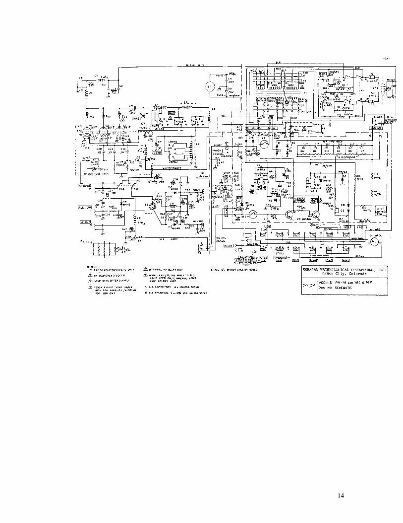
14

15

16

17

Copyright © 2003 M.A. Erickson KK5DR. All rights reserved.
18

![Accumulation of glycerophosphocholine (GPC) renalcells ... · [methyl-14C]choline (3.6,uCi/ml,65,tM;1 Ci =37GBq).The radioactive mediumwasdecanted, andthenthe monolayers were rinsed](https://static.documents.pub/doc/80x56/5e54a4b0b6d2d248e21fa5e6/accumulation-of-glycerophosphocholine-gpc-renalcells-methyl-14ccholine-36uciml65tm1.jpg)


