BY ORDER OF THE SECRETARY OF THE AIR FORCE AIR FORCE HANDBOOK 63-1402 19 MARCH 2001 AIR MOBILITY COMMAND Supplement 21 APRIL 2008 Acquisition AIRCRAFT INFORMATION PROGRAM ACCESSIBILITY: Publications and forms are available for downloading or ordering on the e-Pub- lishing website at www.e-Publishing.af.mil . RELEASABILITY: There are no releasability restrictions on this publication. OPR: HQ AFSC/SEF Certified by: AF/SE (Maj. Gen. Timothy A. Peppe) Pages: 59 (AMC) OPR: HQ AMC/SEF Certified by: HQ AMC/SE (Colonel David R. Miller) Pages: 2 This handbook assists in the establishment of Aircraft Information Programs and provides guidance in selecting recording parameters and functional requirements for information collection systems. (AMC) AFH 63-1402, dated 19 March 2001 is supplemented as follows: provides guidance for the acqui- sition of a standard 2-hour digital Cockpit Voice Recorder (CVR) for all aircraft for which Air Mobility Command (AMC) is lead command. This product does not replace or override current or future regula- tions. This instruction applies only to AMC-owned assets and personnel. Ensure that all records created as a result of processes prescribed in this publication are maintained in accordance with AFMAN 33-363, Management of Records, and disposed of in accordance with the Air Force Records Disposition Schedule (RDS) located at https://afrims.amc.af.mil/ . Refer recommended changes and questions about this pub- lication to the Office of Primary Responsibility (OPR) using the AF IMT 847, Recommendation for Change of Publication; route AF IMT 847s from the field through the appropriate functional chain of command. 1. Introduction ................................................................................................................ 3 2. Program Goals ........................................................................................................... 3 3. Standardization .......................................................................................................... 4 4. AIWG Formation. ...................................................................................................... 6 5. Aircraft Information Management Plan .................................................................... 6 6. Parameter Selection Process. .................................................................................. 6 Certified Current on 6 April 2015
Transcript
BY ORDER OF THESECRETARY OF THE AIR FORCE
AIR FORCE HANDBOOK 63-1402
19 MARCH 2001
AIR MOBILITY COMMANDSupplement
21 APRIL 2008
Acquisition
AIRCRAFT INFORMATION PROGRAM
ACCESSIBILITY: Publications and forms are available for downloading or ordering on the e-Pub-lishing website at www.e-Publishing.af.mil.
RELEASABILITY: There are no releasability restrictions on this publication.
OPR: HQ AFSC/SEF Certified by: AF/SE (Maj. Gen. Timothy A. Peppe)Pages: 59
(AMC) OPR: HQ AMC/SEF Certified by: HQ AMC/SE
(Colonel David R. Miller)Pages: 2
This handbook assists in the establishment of Aircraft Information Programs and provides guidance inselecting recording parameters and functional requirements for information collection systems.
(AMC) AFH 63-1402, dated 19 March 2001 is supplemented as follows: provides guidance for the acqui-sition of a standard 2-hour digital Cockpit Voice Recorder (CVR) for all aircraft for which Air MobilityCommand (AMC) is lead command. This product does not replace or override current or future regula-tions. This instruction applies only to AMC-owned assets and personnel. Ensure that all records created asa result of processes prescribed in this publication are maintained in accordance with AFMAN 33-363,Management of Records, and disposed of in accordance with the Air Force Records Disposition Schedule(RDS) located at https://afrims.amc.af.mil/. Refer recommended changes and questions about this pub-lication to the Office of Primary Responsibility (OPR) using the AF IMT 847, Recommendation forChange of Publication; route AF IMT 847s from the field through the appropriate functional chain ofcommand.
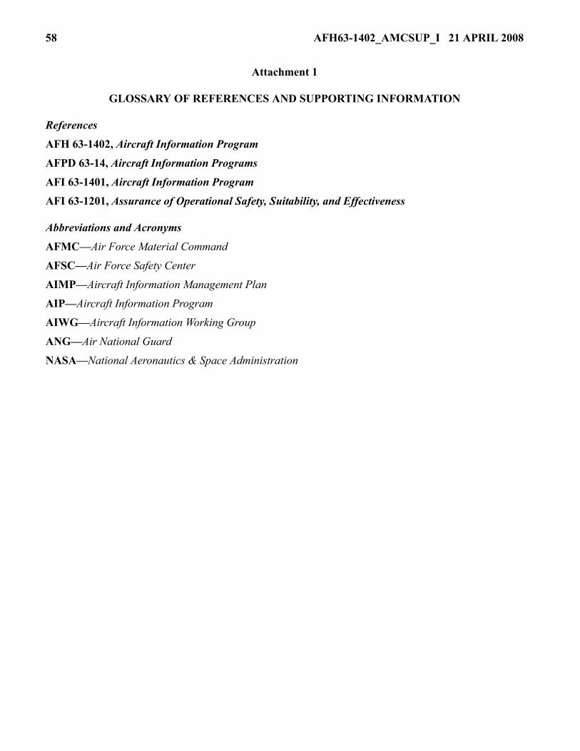
Attachment 1— GLOSSARY OF REFERENCES AND SUPPORTING INFORMATION 58
Attachment 1—(AMC) GLOSSARY OF REFERENCES AND SUPPORTING INFORMATION 59
AFH63-1402_AMCSUP_I 21 APRIL 2008 3
1. Introduction
1.1. The Aircraft Information Program (AIP) supports mishap investigations, Flight OperationalQuality Assurance (FOQA), Reliability Centered Maintenance (RCM), Aircraft and Engine StructuralIntegrity Programs (ASIP/ENSIP), aircraft development programs and training. Its primary goal is tobalance information needs with program resources and operational considerations. This handbookprovides guidance in selecting the appropriate recording parameters and functional requirements forinformation collection systems.
1.2. Mishap investigations are relatively straightforward processes where causes and contributingfactors are determined and used to produce a list of recommendations that should prevent future mis-haps. However, many investigations are inconclusive due to lack of evidence to support mishap sce-narios. This allows insidious conditions to persist and cause future mishaps.
2. Program Goals
2.1. Institutionalize Mishap Investigative Information Requirements
2.1.1. Voice and data recorders for mishap information collection have traditionally lacked advo-cates in the operational and acquisition communities.
2.1.2. Standing policy requiring Flight Data Recorders (FDRs) was issued in 1973. LessonsLearned since that time have illustrated the need to institutionalize a process requiring the explicitaddressing of investigative information data gathering needs.
2.1.3. Numerous customers exist for recorded aircraft information. Training and mishap investi-gation are two obvious reasons to record the performance of the aircraft and crew. Industry haspioneered the use of such information in a proactive mode. A FOQA program examines non-mis-hap flight data in a non-attribution basis to identify hazardous flight procedures and environments.
2.1.4. The engine and structural communities have been performing RCM for many years. Theutility of predicting component wearout or imminent failure has resulted in extensive cost savings.The ability to remove or repair on an as needed basis versus scheduled intervals has saved costsand circumvented component failures leading to mishaps.
2.2. Improve Quality of Mishap Investigation and Reporting
2.2.1. The Air Force forms boards to investigate and determine the cause(s) of mishaps. Whilemany mishaps are straightforward and benefit from surviving crew testimony, the majorityrequires extensive analysis, test and simulation. With modern aircraft employing electronic con-trol systems and video displays, some physical evidence no longer exists at the mishap scene.
2.2.2. Those aircraft with crash survivable data recorders have demonstrated more conclusiveinvestigations than those without recorders. This allows the board to spend less time determiningwhat occurred and more time determining why a mishap occurred.
2.3. Enable FOQA and RCM Programs
2.3.1. Commercial aviation has pioneered the use of “non-mishap” data to detect hazardous oper-ational trends. Examples of such trends would include excessive bank angles, hard landings, andunstabilized approaches. In general, looking for any trigger that would focus attention on a haz-ardous situation.
4 AFH63-1402_AMCSUP_I 21 APRIL 2008
2.3.2. The implementation of a FOQA program presents a number of challenges. One hotlydebated topic is the potential use of FOQA data for punitive action. The identity of the crew mustbe stripped from the data within a short time span and at the lowest organizational level feasible.Consequently, pre-processing of the data must be accomplished in a timely manner to allow inter-viewing the crew for clarification of unique data trends. Flight crew acceptance of FOQA as anon-punitive program is a fundamental building block that cannot be compromised.
2.3.3. Another FOQA challenge is the sheer volume of collected information. Ground supportsoftware requires specific “triggers” to analyze the recorded data and detect hazardous conditions.These suspect records then require closer human evaluation to validate the concern of the expertsystem.
2.3.4. Commercial aviation includes equipment monitoring and trending in its definition ofFOQA while the Air Force refers to it as Reliability Centered-Maintenance (RCM). In any event,it has been shown in both government and industry that impressive cost savings can be accom-plished. Whether it’s extending the removal interval of engines, or detecting excessive fuel con-sumption due to flight control misrigging, both safety and cost avoidance are accomplished.
2.4. Assure Integrated Solution
2.4.1. There are many sources of information on an aircraft. Modern aircraft systems have digitaldatabuses with volumes of parametric data readily available for recorders. Cockpit Voice Record-ers are on many aircraft capturing valuable acoustic information. Training needs often result inHeads-Up-Display (HUD) and Multi-Function Display (MFD) video recorders.
2.4.2. Future weapon systems may have separate acoustic, video and parametric informationsources or achieve optimizations through integration of the technologies. Analyzing the total sys-tem requirements will provide the best and lowest cost solution to the program.
2.5. Enhance Training Effectiveness
2.5.1. Videotapes of Heads-Up-Display (HUD) and Multi-Function Display (MFD) images arecurrently used in crew training. The tapes occasionally survive crash dynamics and contribute toboard investigations. Emerging recording system technologies are capable of integrating acoustic,image and parametric information into crash survivable packages.
2.5.2. Integration of these information sources coupled with real time simulators will providehigher fidelity training opportunities.
2.6. Assist new aircraft development programs.
2.6.1. Identification of information customers should occur prior to the Engineering, Manufactur-ing and Development phase of a program. Early identification will result in the most cost effectiveand integrated solution for the program. Establish the AIWG early to assist in specification ofrequirements.
3. Standardization
3.1. Mishap investigators ascertain the cause of an accident by determining the state of the aircraft,the environment in which it was operating, and the actions of the crew that led up to the event.
3.2. Early recorders were designed to capture the fundamental parameters of altitude, heading, air-speed and vertical acceleration. These parameters enabled the investigator to recreate the flight path
AFH63-1402_AMCSUP_I 21 APRIL 2008 5
of the air vehicle and then postulate what subsystem failures or crew actions would result in such aflight profile. These postulations along with other evidence were used by the investigator to conductanalyses and arrive at a cause of the mishap.
3.3. These fundamental parameters were selected in an environment where parameter recording wasnot as simple an endeavor as it is today. Designing a recording system that would both record param-eters to sufficient resolution and survive an impact was no small feat in the 1950’s. However, as moreresources were put to the task and technology advanced it became feasible to increase both the dura-tion and number of parameters recorded.
3.4. The next generation of parameters added pitch attitude, roll attitude, longitudinal acceleration,pitch trim and engine thrust. These new parameters added to the accuracy of determining aircraftdynamics and most probable crew actions. The requirement to record either control column displace-ment or pitch control surface position was also added at this time to help distinguish when aircraftdynamics were directly attributable to crew action or subsystem failure.
3.5. The next expansion of recorded parameters included most crew control inputs and control sur-face positions thereby clearly distinguishing between crew commanded maneuvers and aircraft fail-ures.
3.6. With the proliferation of digital data buses and computer technology it is now possible to recordhundreds of parameters for many hours. Modern military aircraft demonstrate this ability by record-ing a plethora of information. Consequently, one of the challenges now becomes assuring criticalparameters are captured in crash survivable media and not overlooked while identifying parametersused for other purposes.
3.7. The National Transportation Safety Board (NTSB), the European Organization for Civil AviationEquipment (EUROCAE) and the U.S. military services have periodically recommended specificparameters for mishap investigation. Many of these parameters have subsequently been required to berecorded as a minimum allowable set by various worldwide regulatory agencies such as the FAA andJoint Aviation Authority (JAA).
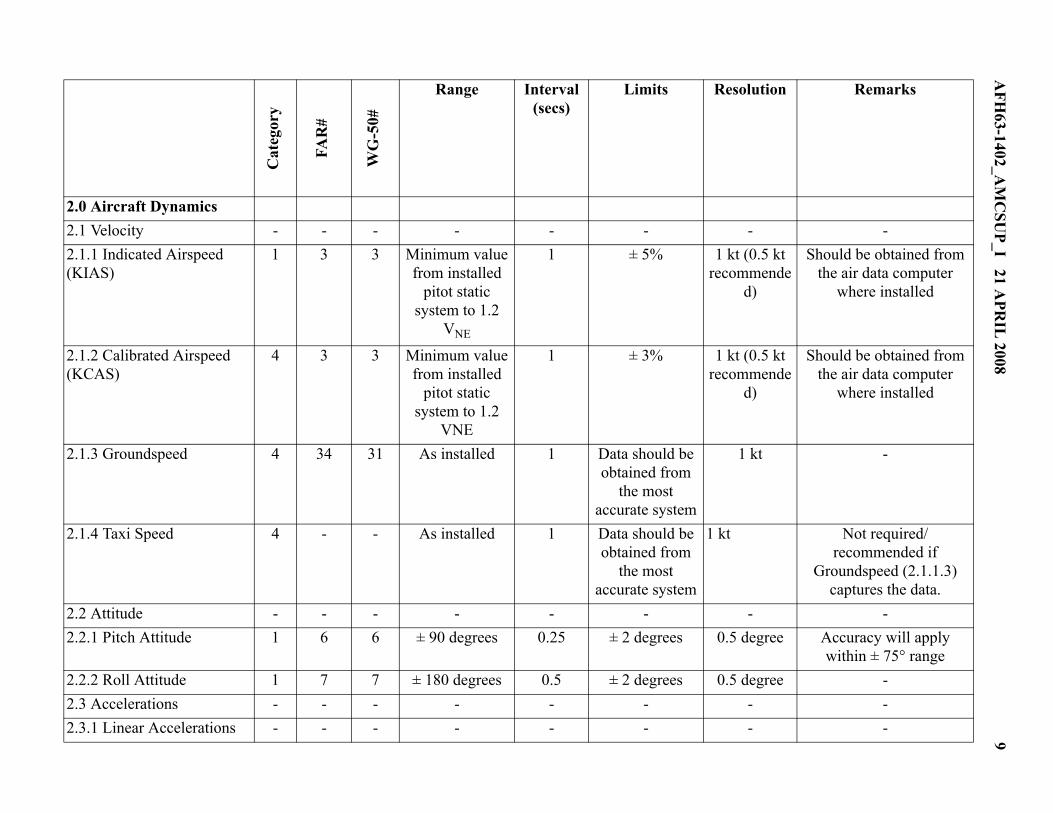
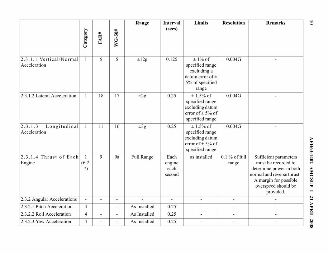
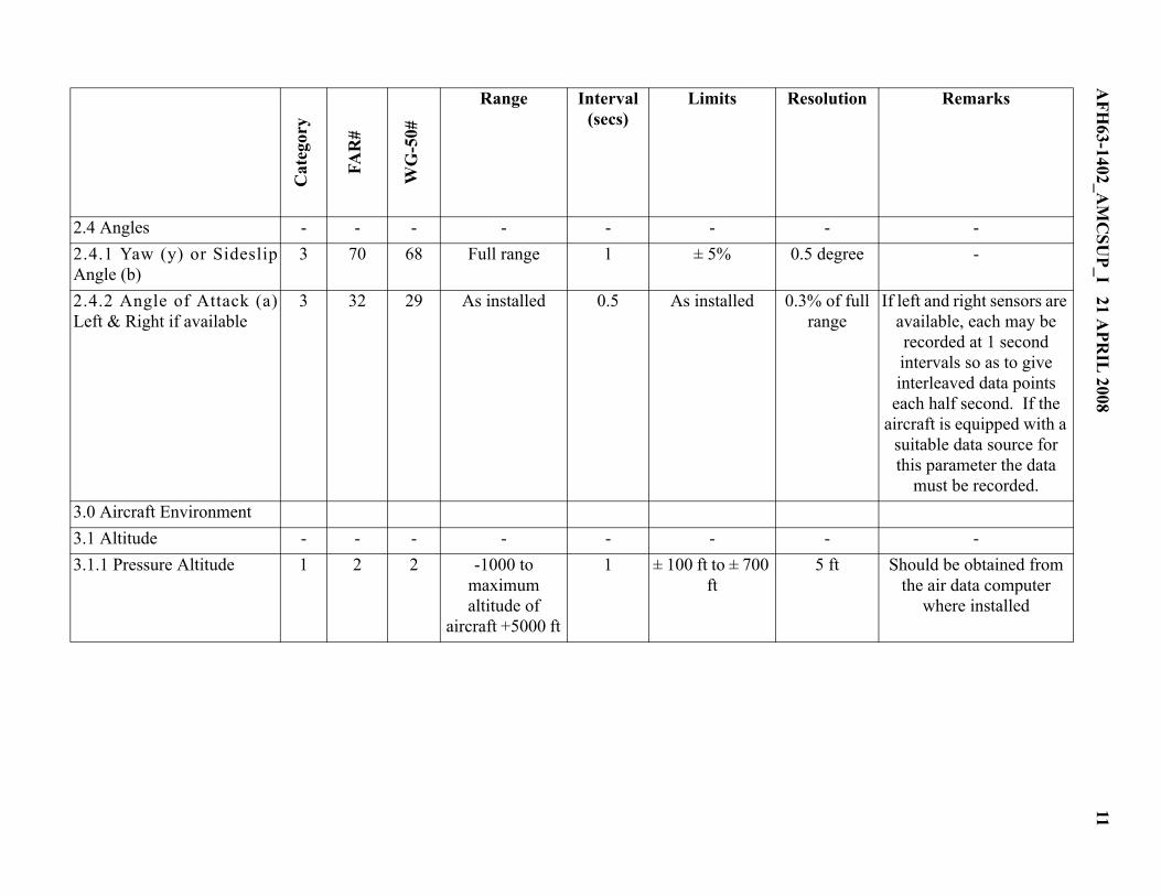
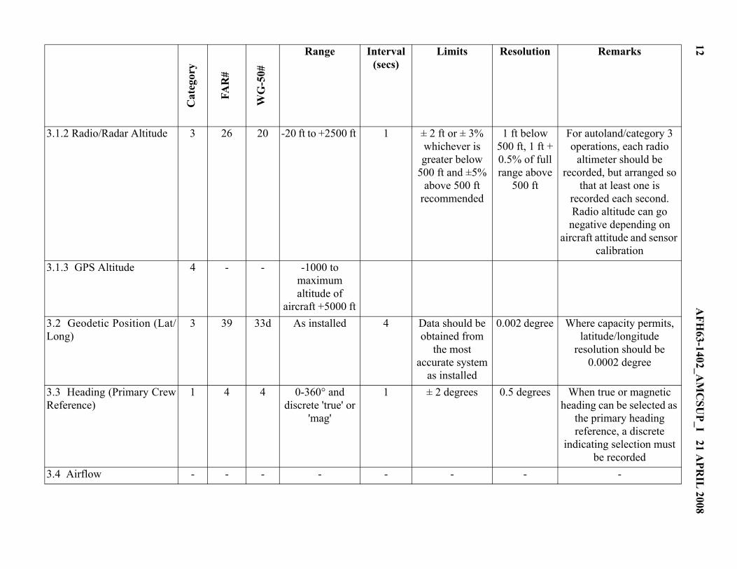
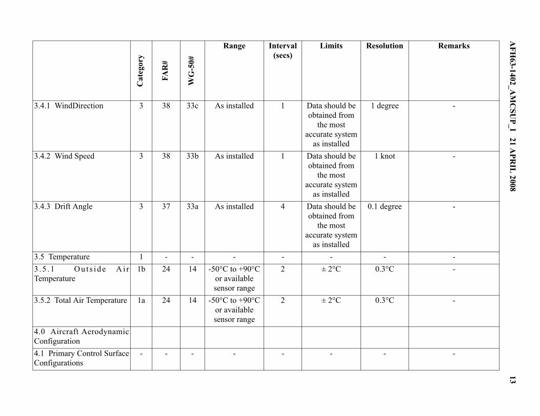
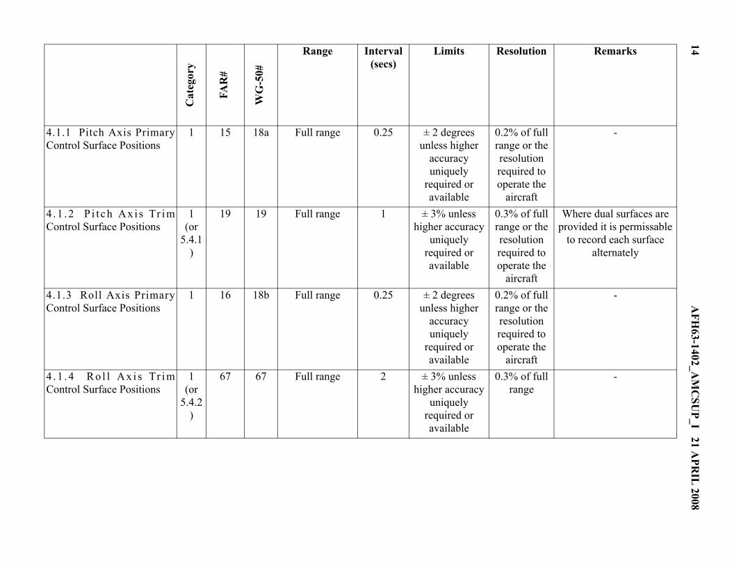
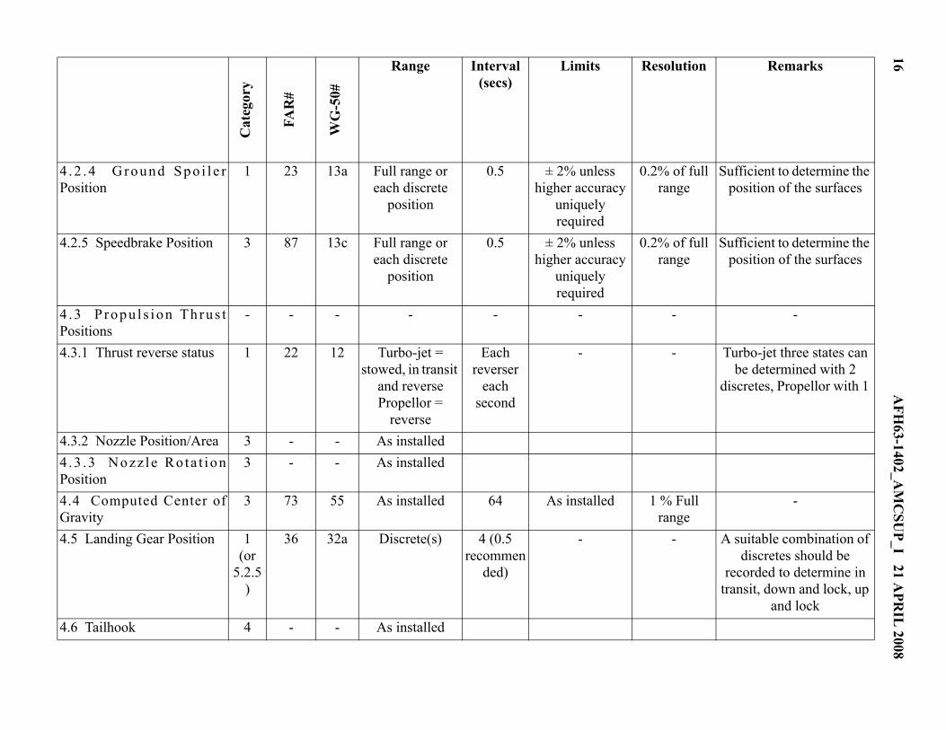
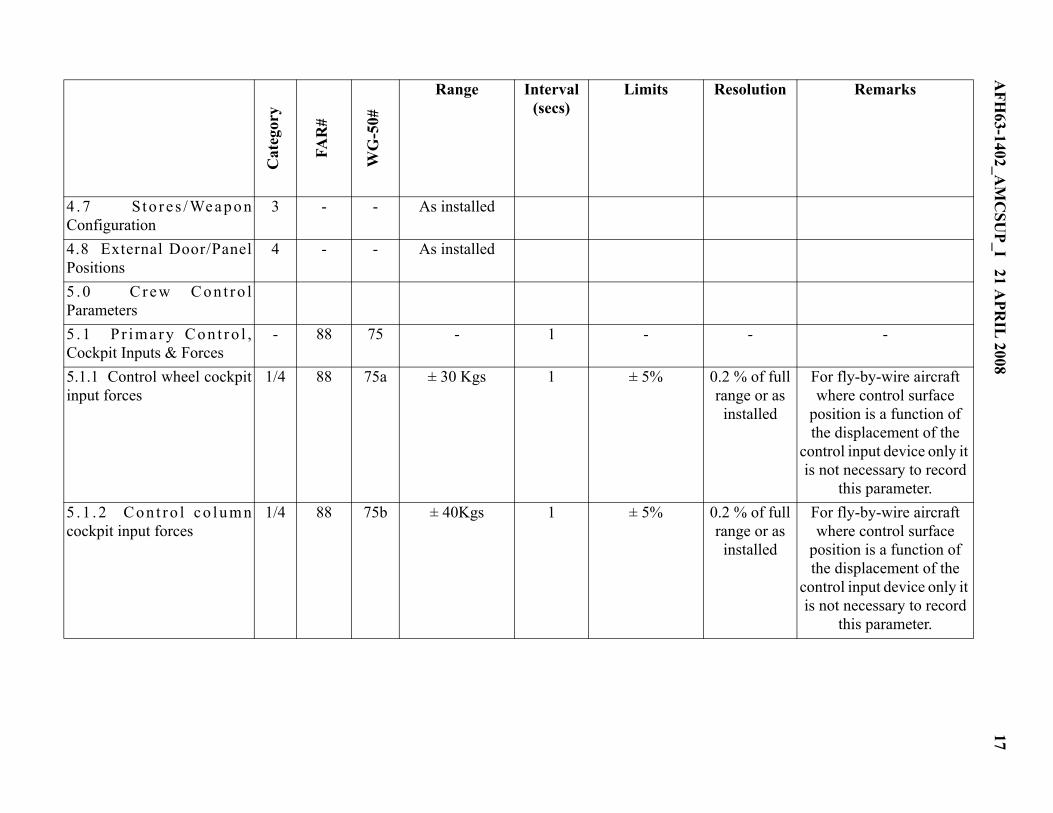
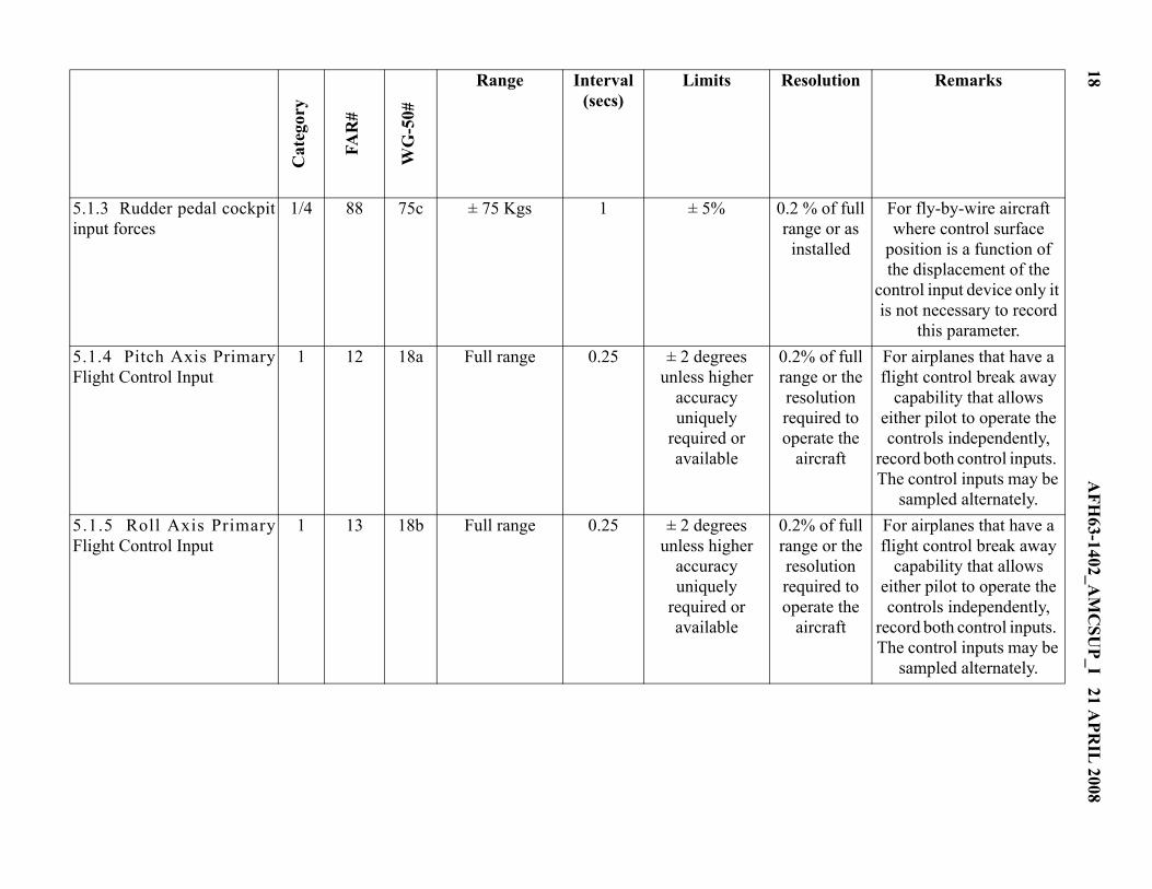
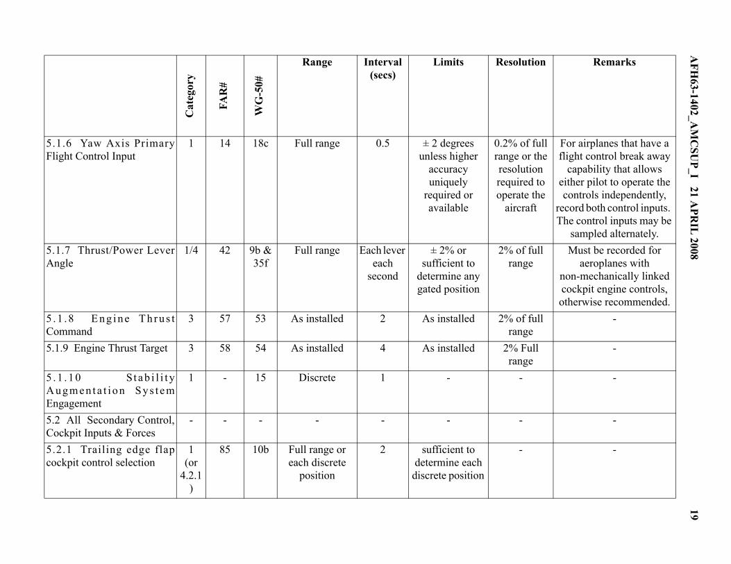
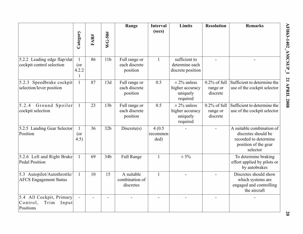
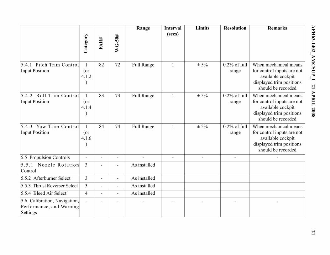
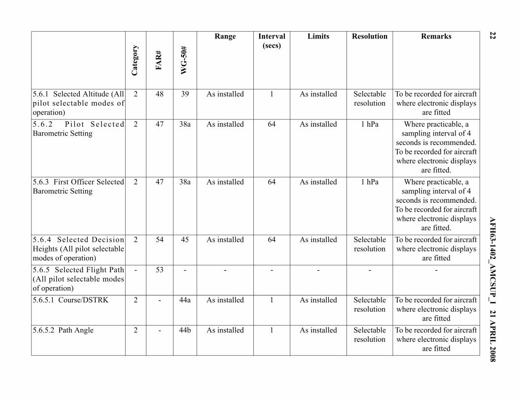
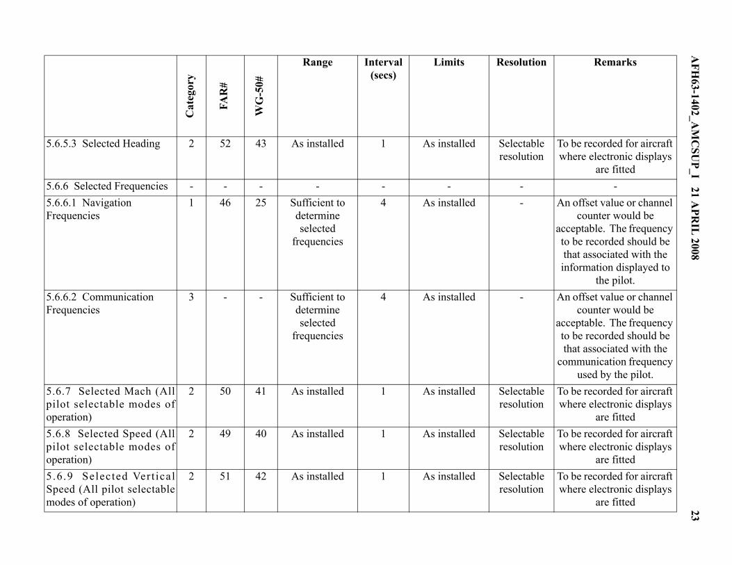
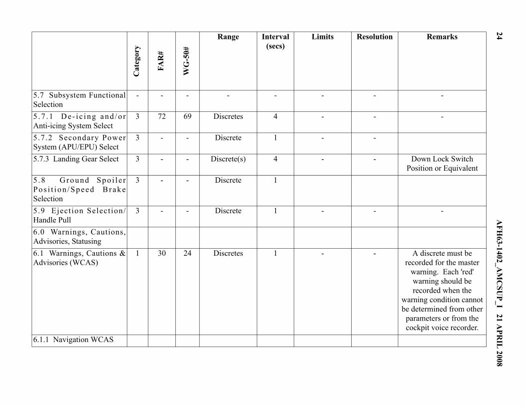
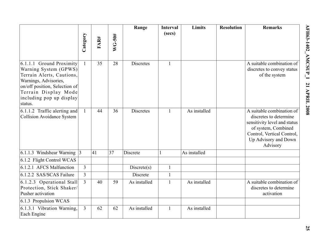
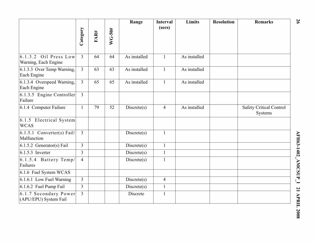
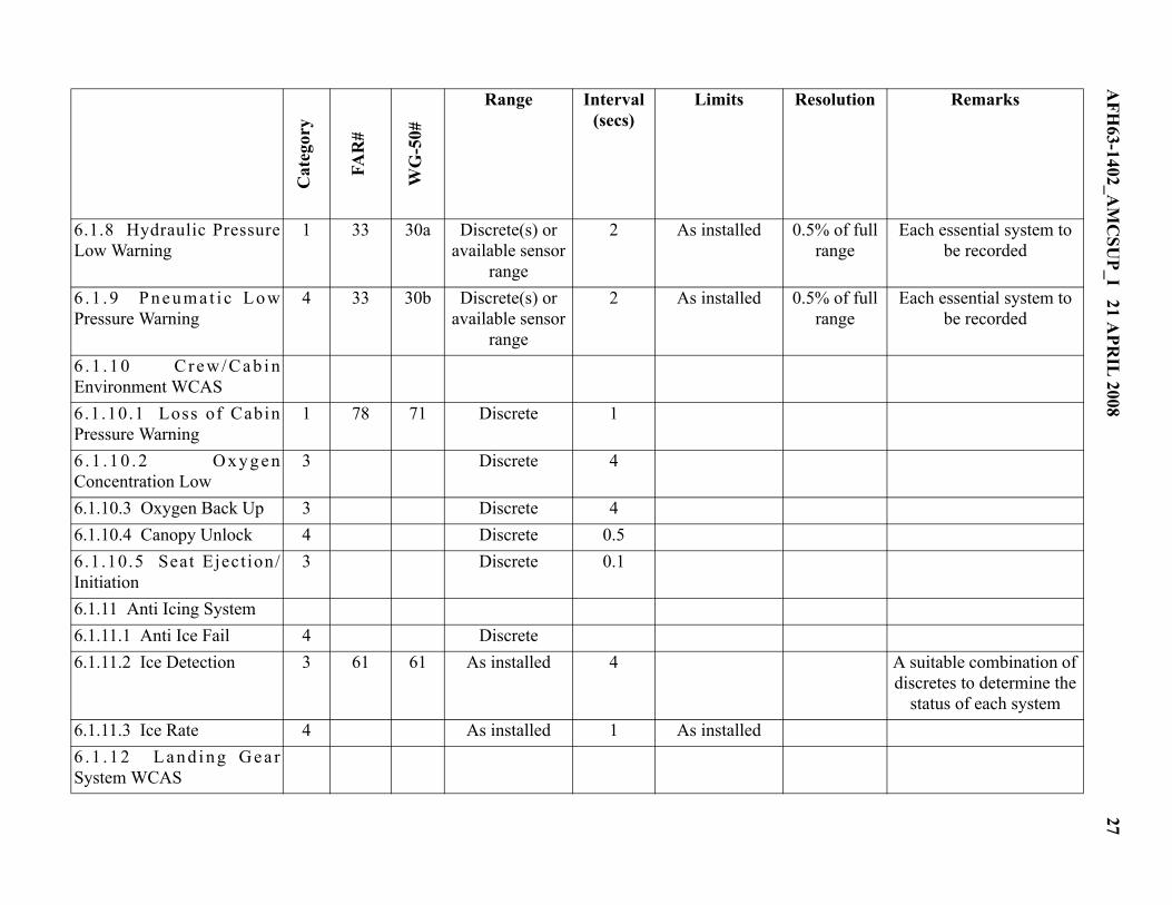
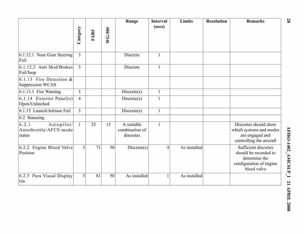
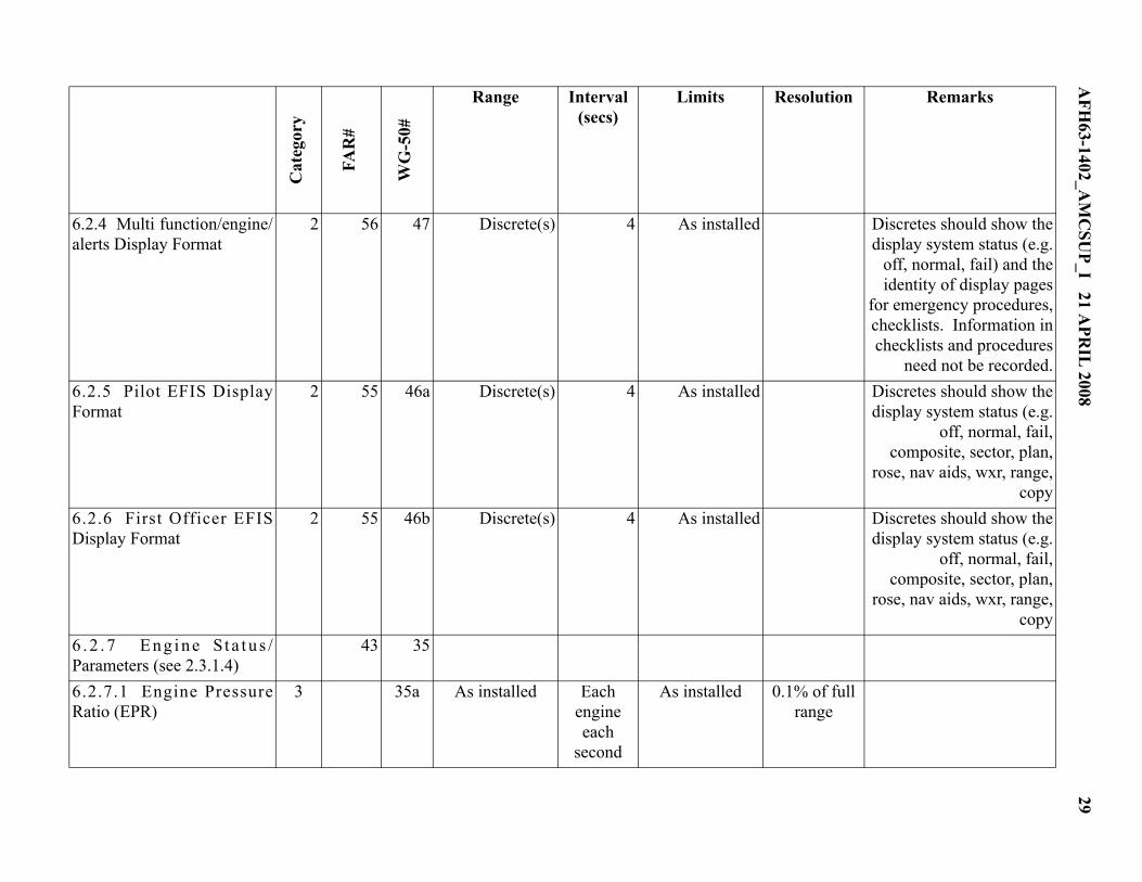
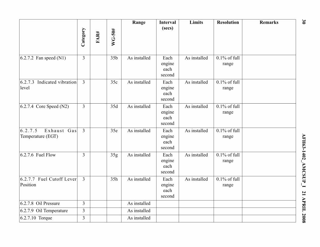
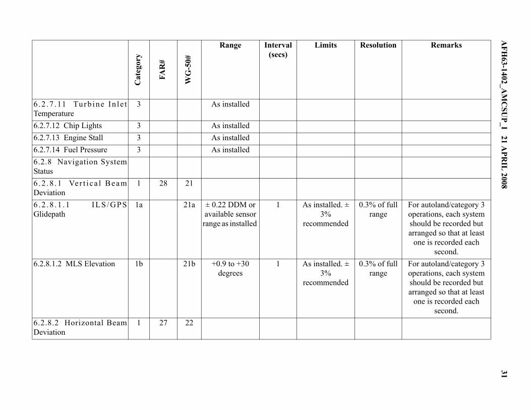
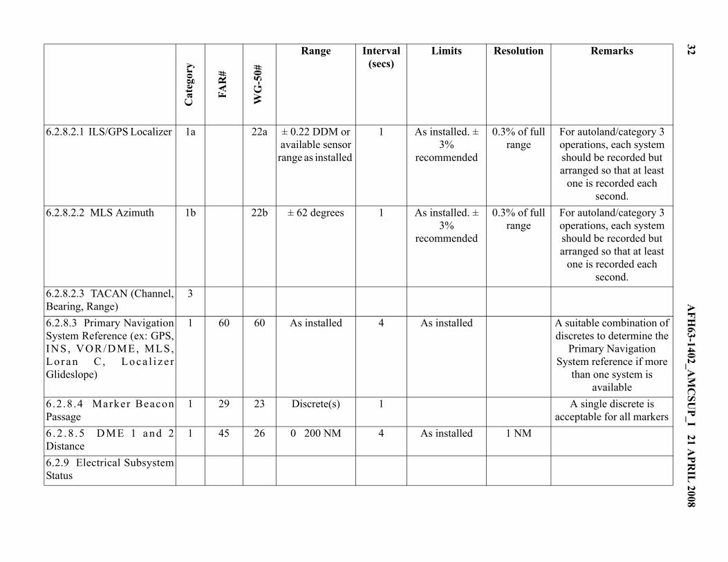
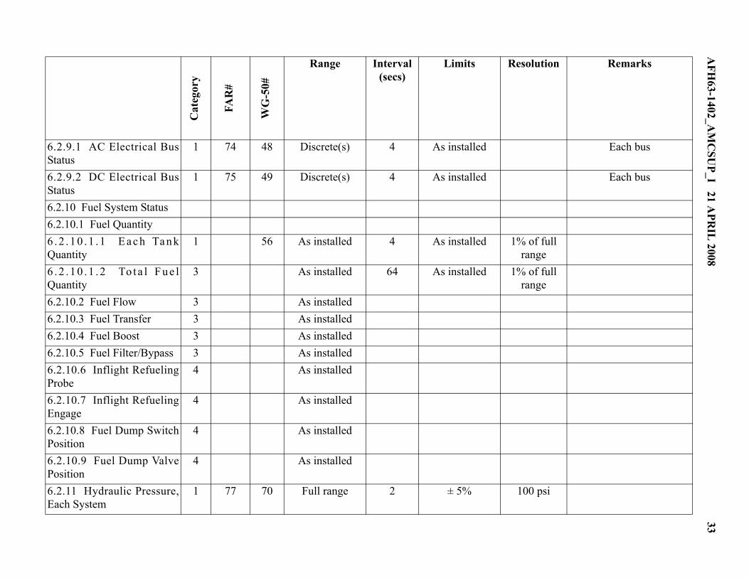
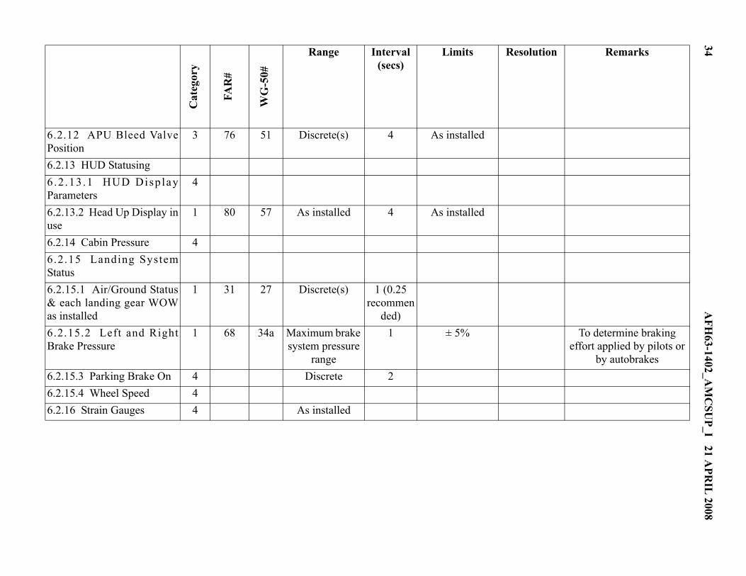
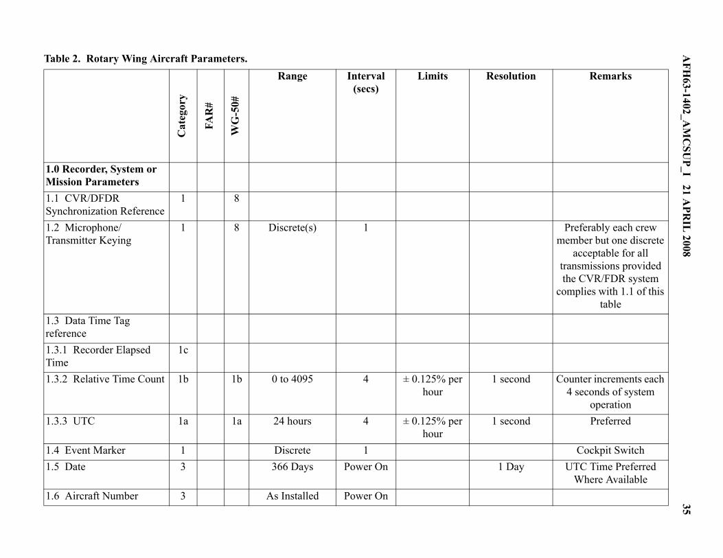
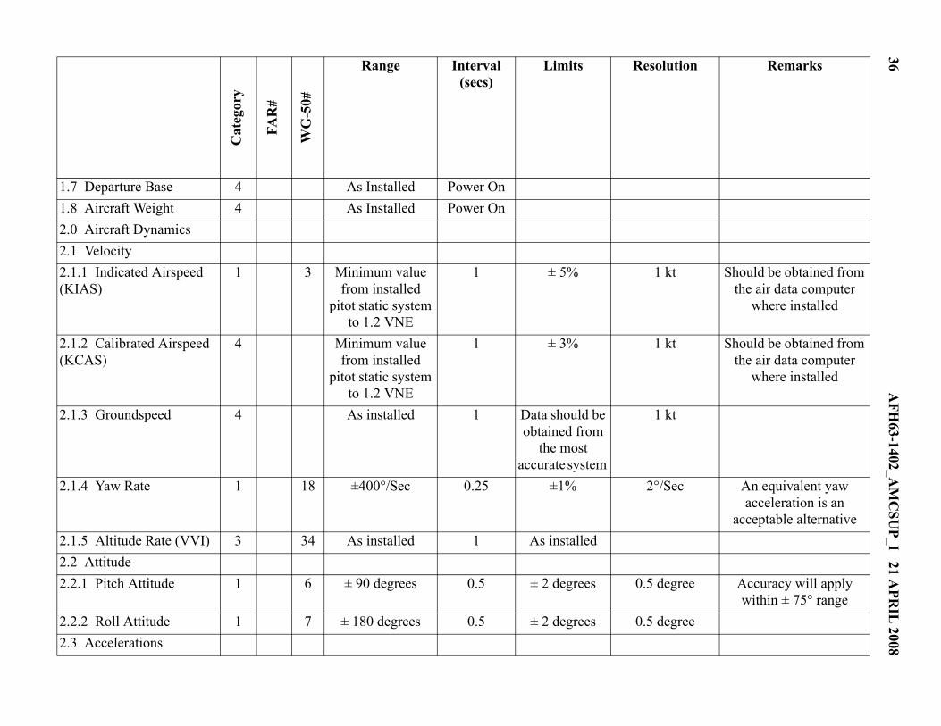
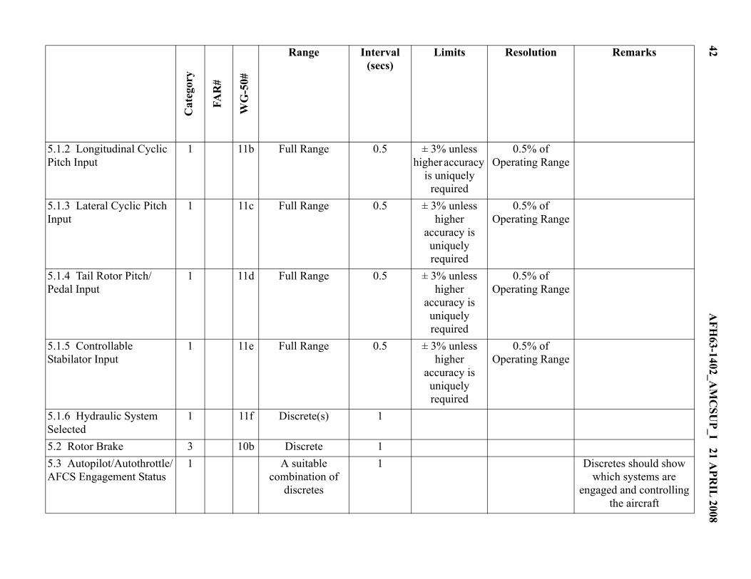
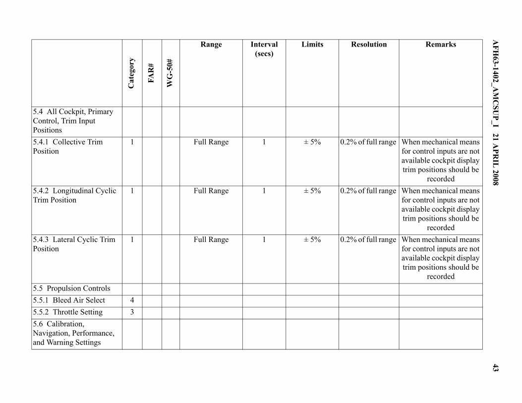
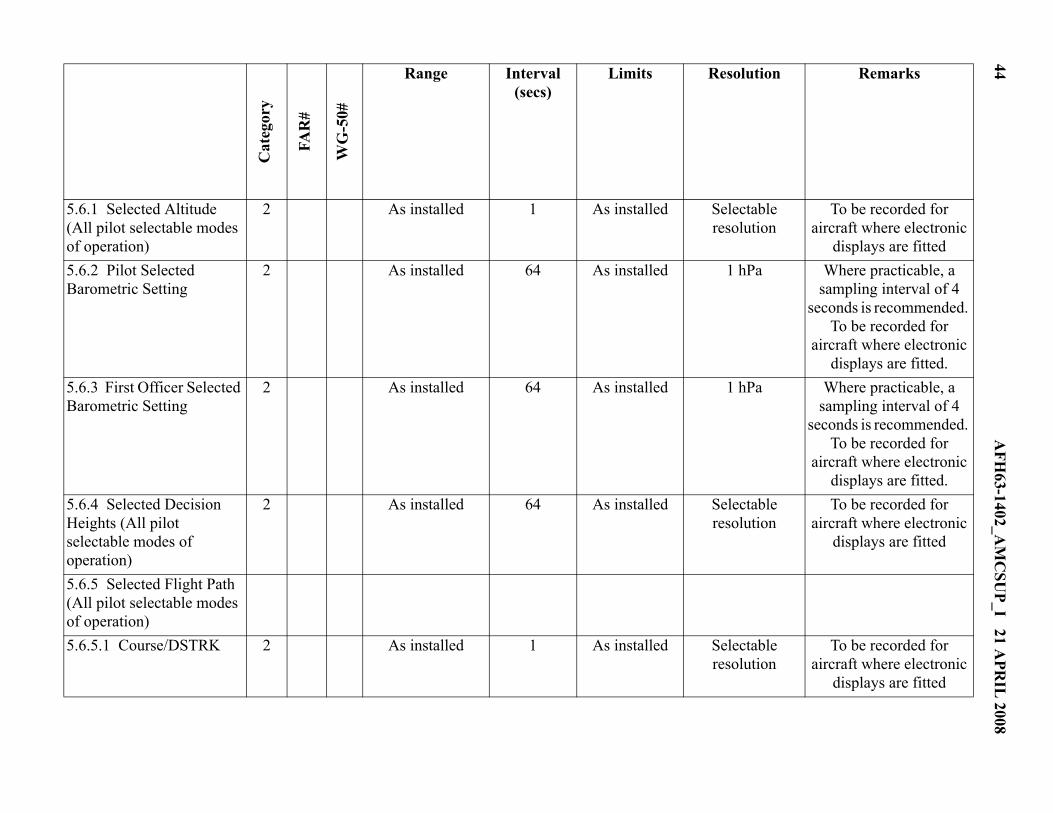
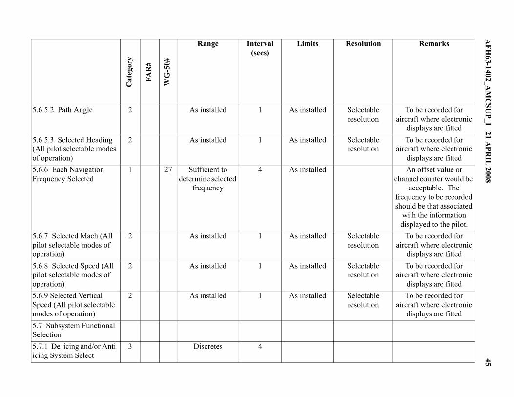
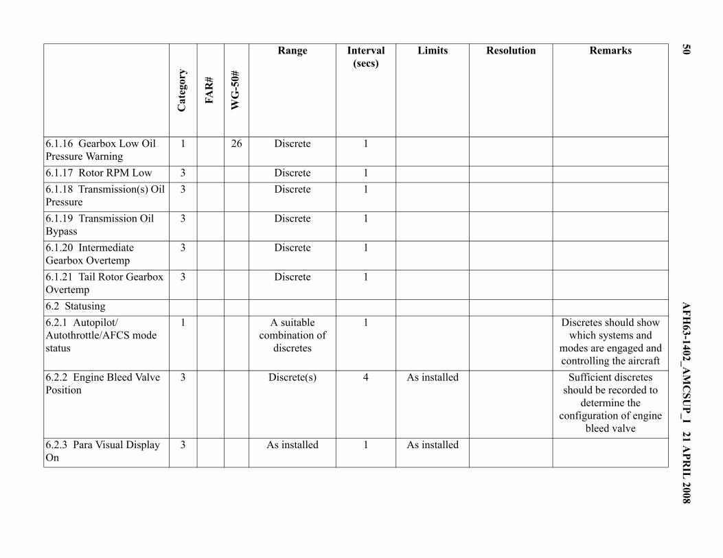
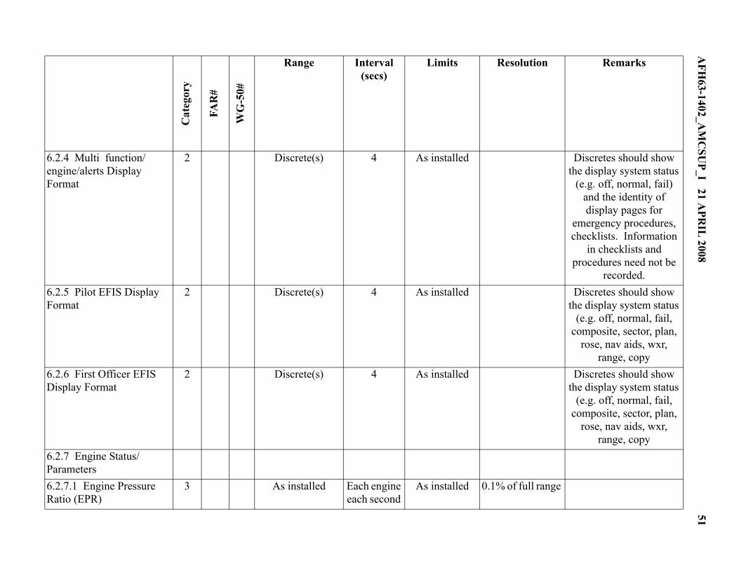
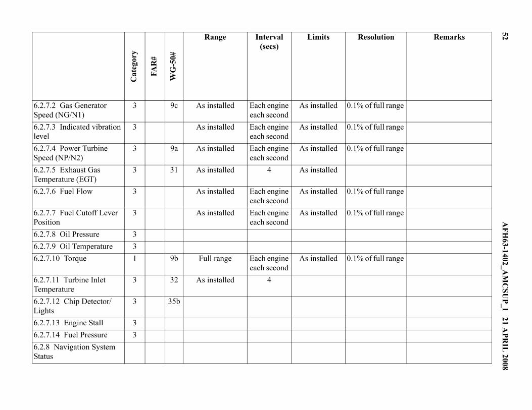
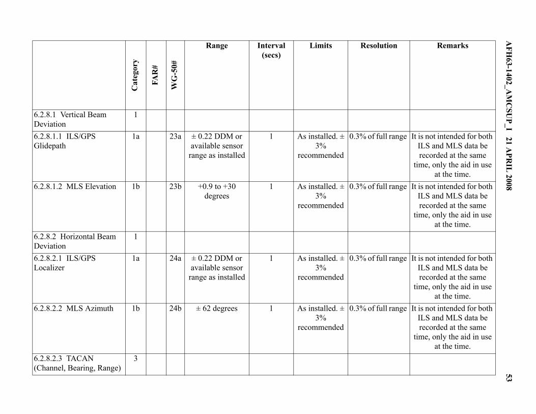
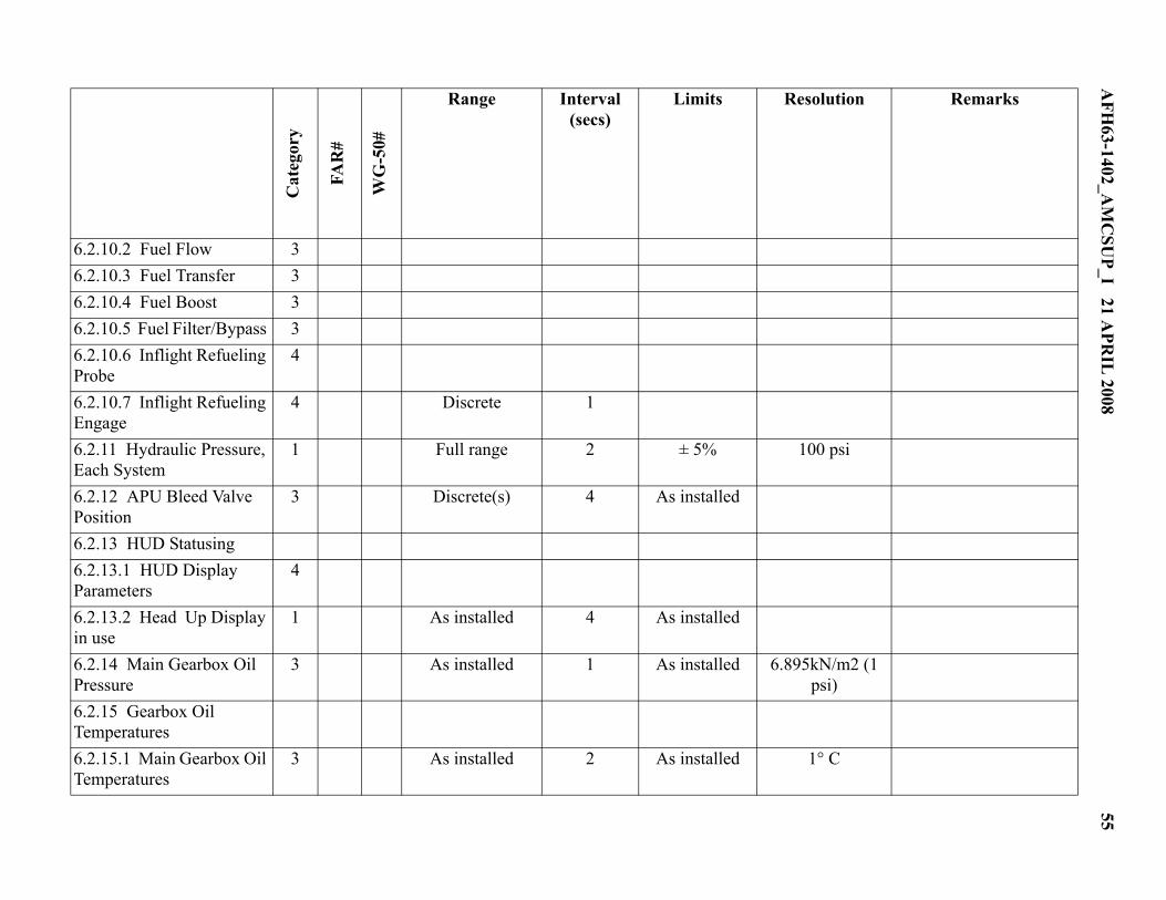
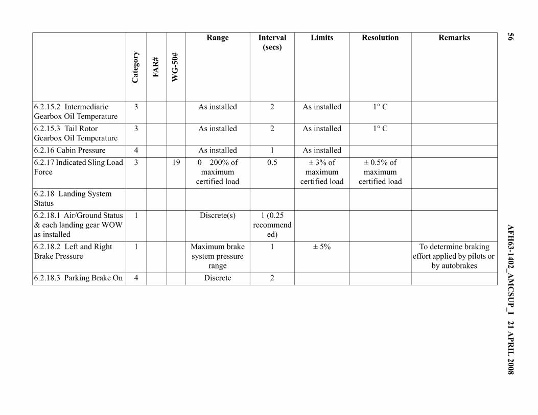
3.8. Table 1. and Table 2. reflect an extensive list of parameters available for recording on both air-craft and helicopters, respectively. These parameters are essential to either investigative or preventa-tive maintenance efforts. While the list is extensive, there will always be “just one more” parameterthat could be captured. Additionally, military aircraft may have mission specific or special equipmentstatus that could also be recorded. So while the list appears complete, mission needs and requirementsmay dictate a more extensive list when deciding on data recording requirements.
3.9. Parameters listed in Table 1. and Table 2. are categorized further based on their importance tothe investigative and mishap prevention process. Category 1 and 2 data satisfy the Chief of Staffdirective that requires a standard set of Digital Flight Data Recorder parameters for inclusion in exist-ing and planned future weapon systems.
3.10. Performance and functional requirements for information recording systems should be deter-mined by exhaustive review of current industry standards and mishap lessons learned. FAA TechnicalStandard Orders (TSOs) such as C-124a and C-123a should be consulted. International standardiza-tion efforts by EUROCAE and International Civil Aviation Organization (ICAO) should be reviewedalong with recommendations of the NTSB and USAF Safety Center. The USAF Safety Center will beable to provide the latest standards and USAF positions relative to these standards.
6 AFH63-1402_AMCSUP_I 21 APRIL 2008
3.10. (AMC) The AMC standard is for all aircraft to have a 2-Hour digital CVR capability. Any ret-rofit of legacy aircraft will be determined by prioritization through the command’s Requirements andPlanning Council Process.
3.11. Federal Aviation Regulation (FAR) 25.1457, Cockpit Voice Recorders and FAR 25.1459, FlightData Recorders should be reviewed by the AIWG for the applicability to each program.
4. AIWG Formation. Each aircraft program will establish an Aircraft Information Working Group(AIWG). The purpose of the AIWG is to ensure that decisions affecting aircraft system capabilitiesaccount for information needs of the operational, maintenance and safety communities.
4.1. The program manager/director or his designated representative will chair the AIWG and overseethe writing of its charter and the Aircraft Information Management Plan (AIMP). The AIWG chairwill solicit appropriate members and advisors in accordance with the guidance of AFI 63-1401. TheAIWG shall assure the members and advisors are empowered to represent their organization and suf-ficiently trained and experienced in the subject matter to contribute positively.
4.2. Membership of the AIWG shall consist of the following individuals whose roles and responsibil-ities are defined in AFI 63-1401.
The chairman
The Chief Engineer or representative
Representatives from the lead command to address operational, logistical and maintenance issues.
Representative from the Air Force Safety Center
4.3. The AIWG will determine the appropriate inspection period for validating the quality and func-tionality of all AIP components.
5. Aircraft Information Management Plan
5.1. The AIMP will address all information needs of the subject aircraft. All forms of informationregardless of recording media or transmission method will be considered.
5.2. Acoustic, imagery, datalink, and parametric information shall be considered when arriving at anintegrated solution for the program.
5.3. The AIWG will advise when the AIMP is required and draft the document for Program Manage-ment approval.
6. Parameter Selection Process.
6.1. To record all possible information on every aircraft would be both cost prohibitive and unrealis-tic. However, a balance must be struck between optimization for the information customer and costavoidance.
6.2. Even though the USAF participates in many commercial standardization efforts we seldom havesufficient influence to require parameters that could be viewed as military unique. Parameter Table 1.and Table 2. were specifically crafted for military aircraft from participation in international workinggroups, recommendations of the NTSB and military lessons learned. The parameter category reflectsit’s hierarchical importance and is described below. References to FAR and WG-50 numbers are
AFH63-1402_AMCSUP_I 21 APRIL 2008 7
solely provided as a tool to correlate AIP parameters to those recommended by national and interna-tional bodies.
1 – Required
2 – Required if electronic displays/glass cockpit otherwise, recommended
3 – Highly desirable if data stream accessible
4 – Recommended if readily available
6.3. Ability for the user to delete geographical, flight path, and performance information should beconsidered in the system design to address both wartime and peacetime security concerns. However,this ability must be validated by the customer of the information being deleted and provided only asunique operational requirements dictate. Sufficient safeguards against arbitrary and capricious dele-tion of information must be included in the system design.
8A
FH63-1402_A
MC
SUP_I 21 A
PRIL
2008Table 1. Fixed Wing Aircraft Parameters.
Cat
egor
y
FAR
#
WG
-50#
Range Interval (secs)
Limits Resolution Remarks
1.0 Recorder, System or Mission Parameters
1.1 CVR/DFDR Synchronization Reference
1 - 8
1.2 Microphone/ Transmitter Keying
1 8 8 Discrete(s) 1 - - Preferably each crew member but one discrete
acceptable for all transmissions provided the
CVR/FDR system complies with 1.1 of this
table 1.3 Data Time Tag reference - - - - - - - - 1.3.1 Recorder Elapsed Time 1c - - 1.3.2 Relative Time Count 1b - 1b 0 to 4095 4 ± 0.125% per
hour 1 second Counter increments each 4
seconds of system operation
1.3.3 UTC 1a 1 1a 24 hours 4 ± 0.125% per hour
1 second Preferred
1.4 Event Marker 1 - 76 Discrete 1 - Cockpit Switch 1.5 Date 3 - 77 366 Days Power On - 1 Day UTC Time Preferred
Where Available 1.6 Aircraft Number 3 - - As Installed Power On - - 1.7 Departure Base 4 - - As Installed Power On - - 1.8 Aircraft Weight 4 - - As Installed Power On
2 50 41 As installed 1 As installed Selectable resolution
To be recorded for aircraft where electronic displays
are fitted 5.6.8 Selected Speed (Allpilot selectable modes ofoperation)
2 49 40 As installed 1 As installed Selectable resolution
To be recorded for aircraft where electronic displays
are fitted 5.6.9 Selected Vert icalSpeed (All pilot selectablemodes of operation)
2 51 42 As installed 1 As installed Selectable resolution
To be recorded for aircraft where electronic displays
are fitted
Cat
egor
y
FAR
#
WG
-50#
Range Interval (secs)
Limits Resolution Remarks
24A
FH63-1402_A
MC
SUP_I 21 A
PRIL
2008
5.7 Subsystem FunctionalSelection
- - - - - - - -
5 . 7 . 1 De - i c ing and /o rAnti-icing System Select
3 72 69 Discretes 4 - - -
5.7.2 Secondary PowerSystem (APU/EPU) Select
3 - - Discrete 1 - -
5.7.3 Landing Gear Select 3 - - Discrete(s) 4 - - Down Lock Switch Position or Equivalent
5 . 8 Ground Spo i l e rPos i t i on /Speed BrakeSelection
3 - - Discrete 1
5 .9 Eject ion Select ion/Handle Pull
3 - - Discrete 1 - - -
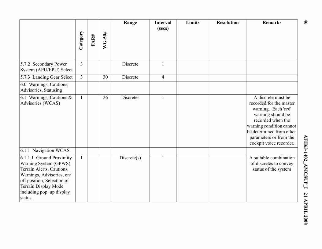
6.0 Warnings, Cautions,Advisories, Statusing
6.1 Warnings, Cautions &Advisories (WCAS)
1 30 24 Discretes 1 - - A discrete must be recorded for the master
warning. Each 'red' warning should be recorded when the
warning condition cannot be determined from other
parameters or from the cockpit voice recorder.
6.1.1 Navigation WCAS
Cat
egor
y
FAR
#
WG
-50#
Range Interval (secs)
Limits Resolution Remarks
AFH
63-1402_AM
CSU
P_I 21 APR
IL 2008
25
6.1.1.1 Ground ProximityWarning System (GPWS)Terrain Alerts, Cautions,Warnings, Advisories, on/off position, Selection ofTe r r a in D i sp l ay Modeincluding pop up displaystatus.
1 35 28 Discretes 1 A suitable combination of discretes to convey status
of the system
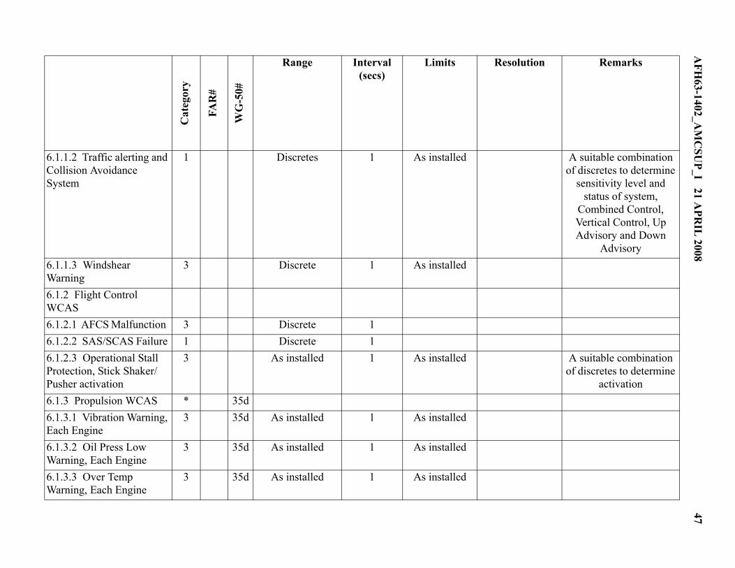
6.1.1.2 Traffic alerting andCollision Avoidance System
1 44 36 Discretes 1 As installed A suitable combination of discretes to determine
6.2.15.1 Air/Ground Status& each landing gear WOWas installed
1 31 27 Discrete(s) 1 (0.25 recommen
ded)
6.2.15.2 Left and RightBrake Pressure
1 68 34a Maximum brake system pressure
range
1 ± 5% To determine braking effort applied by pilots or
by autobrakes 6.2.15.3 Parking Brake On 4 Discrete 2 6.2.15.4 Wheel Speed 4 6.2.16 Strain Gauges 4 As installed
Cat
egor
y
FAR
#
WG
-50#
Range Interval (secs)
Limits Resolution Remarks
AFH
63-1402_AM
CSU
P_I 21 APR
IL 2008
35
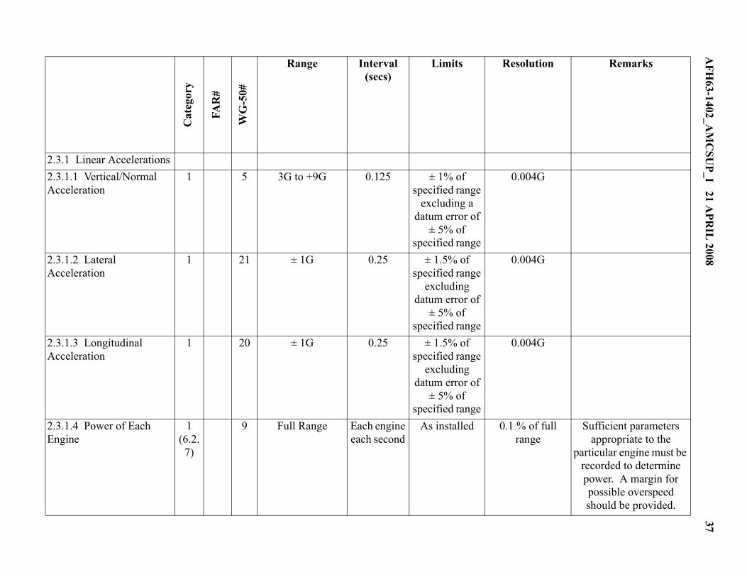
Table 2. Rotary Wing Aircraft Parameters.
Cat
egor
y
FAR
#
WG
-50#
Range
Interval (secs)
Limits Resolution Remarks
1.0 Recorder, System or Mission Parameters
1.1 CVR/DFDR Synchronization Reference
1 8
1.2 Microphone/Transmitter Keying
1 8 Discrete(s) 1 Preferably each crew member but one discrete
acceptable for all transmissions provided the CVR/FDR system
complies with 1.1 of this table
1.3 Data Time Tag reference
1.3.1 Recorder Elapsed Time
1c
1.3.2 Relative Time Count 1b 1b 0 to 4095 4 ± 0.125% per hour
1 second Counter increments each 4 seconds of system
operation 1.3.3 UTC 1a 1a 24 hours 4 ± 0.125% per
hour 1 second Preferred
1.4 Event Marker 1 Discrete 1 Cockpit Switch 1.5 Date 3 366 Days Power On 1 Day UTC Time Preferred
Where Available 1.6 Aircraft Number 3 As Installed Power On
36A
FH63-1402_A
MC
SUP_I 21 A
PRIL
2008
1.7 Departure Base 4 As Installed Power On 1.8 Aircraft Weight 4 As Installed Power On 2.0 Aircraft Dynamics 2.1 Velocity 2.1.1 Indicated Airspeed (KIAS)
1 3 Minimum value from installed
pitot static system to 1.2 VNE
1 ± 5% 1 kt Should be obtained from the air data computer
where installed
2.1.2 Calibrated Airspeed (KCAS)
4 Minimum value from installed
pitot static system to 1.2 VNE
1 ± 3% 1 kt Should be obtained from the air data computer
where installed
2.1.3 Groundspeed 4 As installed 1 Data should be obtained from
the most accurate system
1 kt
2.1.4 Yaw Rate 1 18 ±400°/Sec 0.25 ±1% 2°/Sec An equivalent yaw acceleration is an
acceptable alternative 2.1.5 Altitude Rate (VVI) 3 34 As installed 1 As installed 2.2 Attitude 2.2.1 Pitch Attitude 1 6 ± 90 degrees 0.5 ± 2 degrees 0.5 degree Accuracy will apply
within ± 75° range 2.2.2 Roll Attitude 1 7 ± 180 degrees 0.5 ± 2 degrees 0.5 degree 2.3 Accelerations
Cat
egor
y
FAR
#
WG
-50#
Range
Interval (secs)
Limits Resolution Remarks
AFH
63-1402_AM
CSU
P_I 21 APR
IL 2008
37
2.3.1 Linear Accelerations 2.3.1.1 Vertical/Normal Acceleration
1 5 3G to +9G 0.125 ± 1% of specified range
excluding a datum error of
± 5% of specified range
0.004G
2.3.1.2 Lateral Acceleration
1 21 ± 1G 0.25 ± 1.5% of specified range
excluding datum error of
± 5% of specified range
0.004G
2.3.1.3 Longitudinal Acceleration
1 20 ± 1G 0.25 ± 1.5% of specified range
excluding datum error of
± 5% of specified range
0.004G
2.3.1.4 Power of Each Engine
1 (6.2.7)
9 Full Range Each engine each second
As installed 0.1 % of full range
Sufficient parameters appropriate to the
particular engine must be recorded to determine power. A margin for possible overspeed should be provided.
Cat
egor
y
FAR
#
WG
-50#
Range
Interval (secs)
Limits Resolution Remarks
38A
FH63-1402_A
MC
SUP_I 21 A
PRIL
2008
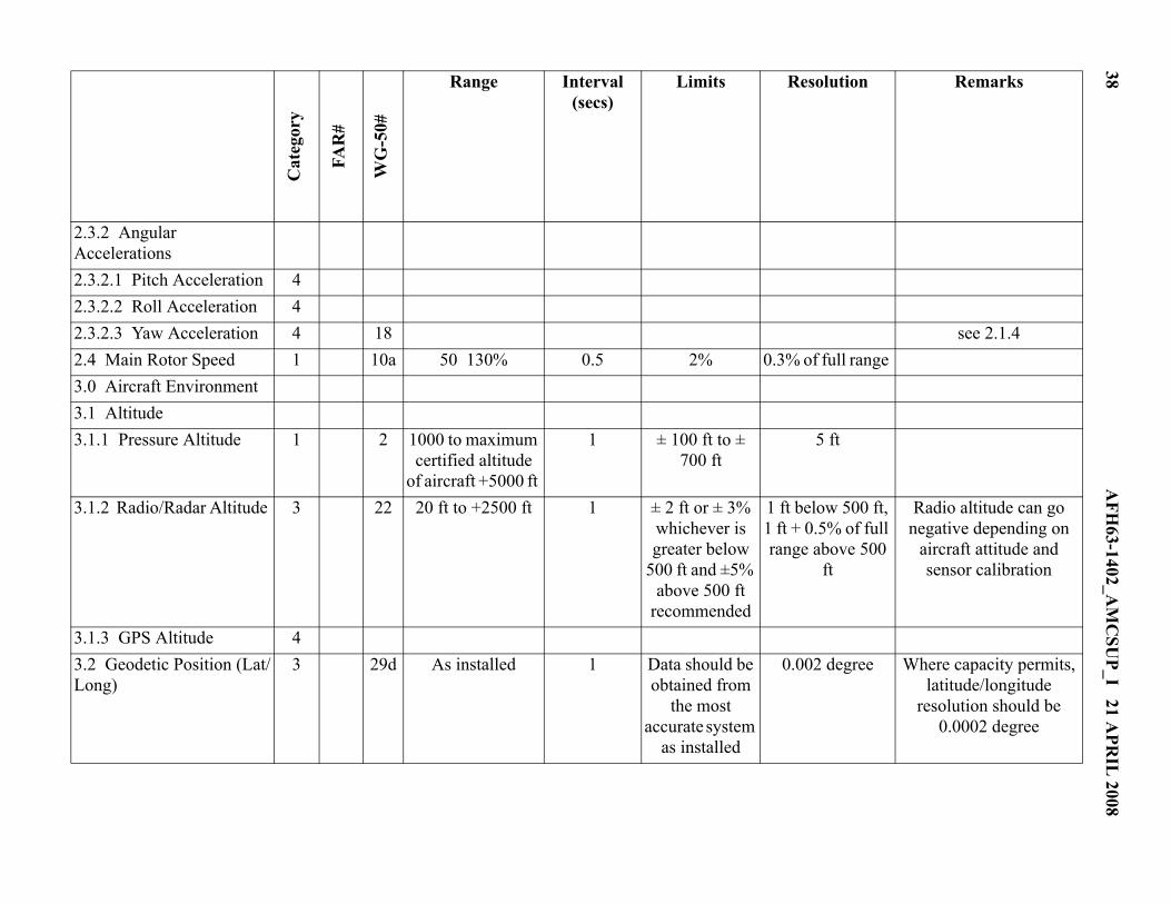
2.3.2 Angular Accelerations
2.3.2.1 Pitch Acceleration 4 2.3.2.2 Roll Acceleration 4 2.3.2.3 Yaw Acceleration 4 18 see 2.1.4 2.4 Main Rotor Speed 1 10a 50 130% 0.5 2% 0.3% of full range 3.0 Aircraft Environment 3.1 Altitude 3.1.1 Pressure Altitude 1 2 1000 to maximum
certified altitude of aircraft +5000 ft
1 ± 100 ft to ± 700 ft
5 ft
3.1.2 Radio/Radar Altitude 3 22 20 ft to +2500 ft 1 ± 2 ft or ± 3% whichever is greater below
500 ft and ±5% above 500 ft
recommended
1 ft below 500 ft, 1 ft + 0.5% of full range above 500
ft
Radio altitude can go negative depending on
aircraft attitude and sensor calibration
3.1.3 GPS Altitude 4 3.2 Geodetic Position (Lat/Long)
3 29d As installed 1 Data should be obtained from
the most accurate system
as installed
0.002 degree Where capacity permits, latitude/longitude
resolution should be 0.0002 degree
Cat
egor
y
FAR
#
WG
-50#
Range
Interval (secs)
Limits Resolution Remarks
AFH
63-1402_AM
CSU
P_I 21 APR
IL 2008
39
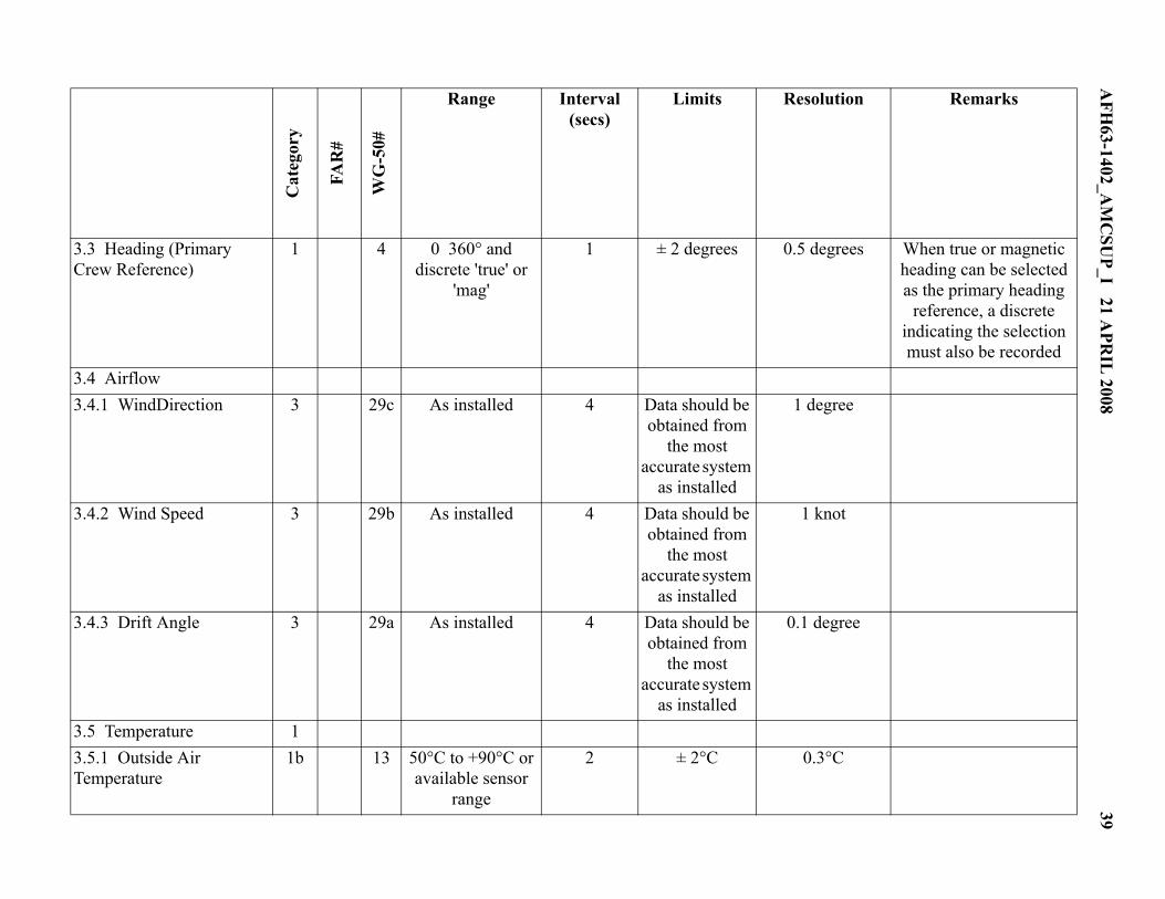
3.3 Heading (Primary Crew Reference)
1 4 0 360° and discrete 'true' or
'mag'
1 ± 2 degrees 0.5 degrees When true or magnetic heading can be selected as the primary heading
reference, a discrete indicating the selection must also be recorded
3.4 Airflow 3.4.1 WindDirection 3 29c As installed 4 Data should be
obtained from the most
accurate system as installed
1 degree
3.4.2 Wind Speed 3 29b As installed 4 Data should be obtained from
the most accurate system
as installed
1 knot
3.4.3 Drift Angle 3 29a As installed 4 Data should be obtained from
the most accurate system
as installed
0.1 degree
3.5 Temperature 1 3.5.1 Outside Air Temperature
1b 13 50°C to +90°C or available sensor
range
2 ± 2°C 0.3°C
Cat
egor
y
FAR
#
WG
-50#
Range
Interval (secs)
Limits Resolution Remarks
40A
FH63-1402_A
MC
SUP_I 21 A
PRIL
2008
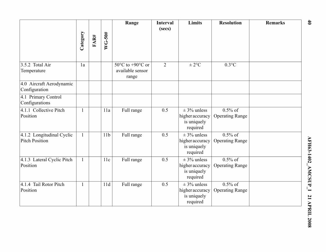
3.5.2 Total Air Temperature
1a 50°C to +90°C or available sensor
range
2 ± 2°C 0.3°C
4.0 Aircraft Aerodynamic Configuration
4.1 Primary Control Configurations
4.1.1 Collective Pitch Position
1 11a Full range 0.5 ± 3% unless higher accuracy
is uniquely required
0.5% of Operating Range
4.1.2 Longitudinal Cyclic Pitch Position
1 11b Full range 0.5 ± 3% unless higher accuracy
is uniquely required
0.5% of Operating Range
4.1.3 Lateral Cyclic Pitch Position
1 11c Full range 0.5 ± 3% unless higher accuracy
is uniquely required
0.5% of Operating Range
4.1.4 Tail Rotor Pitch Position
1 11d Full range 0.5 ± 3% unless higher accuracy
is uniquely required
0.5% of Operating Range
Cat
egor
y
FAR
#
WG
-50#
Range
Interval (secs)
Limits Resolution Remarks
AFH
63-1402_AM
CSU
P_I 21 APR
IL 2008
41
4.1.5 Controllable Stabilator Position
1 11e Full range 0.5 ± 3% unless higher
accuracy is uniquely required
0.5% of Operating Range
4.1.6 Hydraulic System Active
1 11f Discrete 1
4.2 Computed Center of Gravity
3 As installed 64 As installed 1 % Full range
4.3 Landing Gear Position 3 30 Discrete(s) 4 A suitable combination of discretes should be