Page 1
BY ORDER OF THE
SECRETARY OF THE AIR FORCE
AIR FORCE INSTRUCTION 11-2F-15E,
VOLUME 3
5 APRIL 2013
Flying Operations
F-15E –OPERATIONS PROCEDURES
COMPLIANCE WITH THIS PUBLICATION IS MANDATORY
ACCESSIBILITY: Publications and forms are available on the e-Publishing website at
www.e-publishing.af.mil for downloading or ordering.
RELEASABILITY: There are no releasability restrictions on this publication.
OPR: ACC/A3TO
Supersedes: AFI11-2F-15EV3,
11 August 2009
Certified by: AF/A3O
(Maj Gen James J. Jones)
Pages: 90
This volume establishes effective and safe operations of the F-15E and implements AFPD 11-2,
Aircrew Operations; AFPD 11-4, Aviation Service; AFI 11-200, Aircrew Training,
Standardization/Evaluation, and General Operations Structure; and AFI 11-202V3, General
Flight Rules. It establishes the minimum Air Force operations procedures for personnel
performing duties in the F-15E. This publication applies to the US Air Force Reserve Command
(AFRC). This publication does not apply to the Air National Guard (ANG). Selected paragraphs
of this publication do not apply to all Air Force units. When an exception exists to the
requirements of a paragraph, the exception is indicated in a parenthetical within the paragraph, or
by using subparagraphs directed at specific units. MAJCOMs, Direct Reporting Units (DRU) and
Field Operating Agencies (FOA) will forward proposed MAJCOM/DRU/FOA-level
supplements to this volume to AFFSA/A3OF, through HQ ACC/A3TO, for approval prior to
publication IAW AFI 11-200. Copies of approved and published supplements will be provided
by the issuing office to AFFSA/A3OF, ACC/A3TO, and the user MAJCOM/ DRU/FOA offices
of primary responsibility (OPR). IAW AFI 11-200, field units below MAJCOM/DRU/FOA level
will forward proposed supplements to the lead AFI OPR for review and coordination prior to
approval and publication. NOTE: The above applies only to those DRUs/FOAs that report
directly to HQ USAF. Keep supplements current by complying with AFI 33-360, Publications
and Forms Management.
Waiver authority to this publication is set out in para 1.3 See para 1.4 for guidance on submitting
comments and suggesting improvements.
Page 2
2 AFI11-2F-15EV3 5 APRIL 2013
This instruction requires the collection or maintenance of information protected by the Privacy
Act of 1974. The authority to collect and maintain the records prescribed in this instruction are
37 USC 301a, Incentive Pay; Public Law 92-204 (Appropriations Act for 1973), Section 715;
Public Law 93-570 (Appropriations Act for 1974); Public Law 93-294 (Aviation Career
Incentive Act of 1974); DoD Instruction 7730.57, Aviation Career Incentive Act of 1974 and
Required Annual Report; AFI 11-401, Aviation Management; and E.O. 9397, Numbering System
for Federal Accounts Relating to Individual Persons. System of records notice F011 AF/XOA,
Aviation Resource Management System (ARMS), applies and is available at
http://privacy.defense.gov/notices/usaf/.
Records Disposition. Ensure that all records created as a result of processes prescribed in this
publication are maintained in accordance with Air Force Manual (AFMAN) 33-363,
Management of Records, and disposed of in accordance with the Air Force Records Disposition
Schedule (RDS) located in the Air Force Records Information Management System (AFRIMS).
NOTE: This instruction contains references to the following field (subordinate level)
publications and forms which, until converted to departmental level publications and forms may
be obtained from the respective MAJCOM publication distribution office.
SUMMARY OF CHANGES
This document has been substantially revised and must be completely reviewed. Paragraphs
have been reorganized to increase standardization with other AFI 11-2MDS Vol 3s and improve
logical flow. A thorough review of this instruction is required by all aircrew to understand the
implications of the reorganization.
Changes by chapter and paragraph are as follows: Chapter 2 Listed references for Flight Map
Preparation. 2.2.1 Added reference to asymmetry. 2.4.1.3 Updated TO references. 2.4.4.1
References AFMAN 11-217, V2 for low level planning and map guidance. 2.4.4.5 Updated
Terrain Following TF Flight Map Preparation; added Terrain at 1NM data, and added Command
level-off begins data. 2.6.4 Added FTU guidance for Multiple Sortie Days and changed
“missions” to “sorties”. Chapter 3 3.7.3 Added asymmetric loading guidance for formation
takeoffs. 3.6.9.1 Added TO 1F-15E-1-2-1CL-1 reference for Hot Brakes ops. 3.9.1 Deleted
references to AFTTP 3-3.F-15E and AFTTP 3.1.F-15E. 3.13.4 Updated usage of term “US
NAS”. 3.17.6.4 Expanded “Show of Force” guidance. 3.17.7 Expanded definition of Low
Altitude to include less than 5,000’ AGL. 3.17.10 Updated Low Altitude Target Pod usage
guidance. 3.18.5 Updated TO reference. 3.19 Tied Joker/Bingo Fuel guidance to AFI 11-214.
3.22.2 Updated go-around procedures. 3.27 Deleted reference and guidance for Formation
Landings. 3.27.1 Added reference to asymmetries greater than 3,000 ft-lbs. 3.31 Updated Night
Join-Up verbiage. 3.32.2 Added references to Spatial Disorientation. 3.36 Updated Change of
Aircraft Control verbiage. 3.38 Updated F-15E Crew Duties guidance. 3.38.3.1 Added an
exception for WSO Flying guidance. 3.39 Updated AAI/EID flight guidance. Chapter 4
Updated guidance for EADI usage in day/night and IMC. 4.1 Complete revamp of HUD, EADI
usage. 4.3.2.1 Replaced AFTTP 3-13.F-15E reference for “Use a minimum of 20 seconds takeoff
spacing. Added reference to FDL usage. Chapter 5 Cleaned up maneuvering limitations and
added asymmetry references. 5.2 Updated Simulated Gun Employment guidance. 5.3.3 Clarified
maneuvering limits with external wing tanks. Chapter 6 Revamped Air-to-Surface Weapons
Page 3
AFI11-2F-15EV3 5 APRIL 2013 3
Employment. 6.1 Clarified guidance for Master Arm procedures. 6.2 Added AFI 11-214
guidance/restrictions. 6.3 Added expanded Strafe guidance. 6.6.3.2 Changed “Ballistic” to
“Unguided”; updated procedures and systems requirements. 6.7 Added robust Nighttime Targets
of Opportunity section. Chapter 7 7.2.3 Deleted. 7.3.5 Updated Brake Overheat direction. 7.5.3
Expanded/updated Surface Attack NORDO Procedures. 7.6 Updated Severe Weather Penetration
guidance. 7.9.2 Added reference to AFI 11-214. 7.11.5.2 clarified Supervisory Requirements and
further defined IQT pilot status. Chapter 8 8.1 Deleted verbiage requiring distribution of
Chapter 8.
Chapter 1—GENERAL GUIDANCE 7
1.1. Abbreviations, Acronyms, and Terms. .................................................................. 7
1.2. Responsibilities. ..................................................................................................... 7
1.3. Waivers. ................................................................................................................. 7
1.4. Deviations. ............................................................................................................. 7
1.5. Processing Changes. .............................................................................................. 7
Chapter 2—MISSION PLANNING 8
2.1. Responsibilities. ..................................................................................................... 8
2.2. General Procedures. ............................................................................................... 8
2.3. Unit Developed Checklists and Local Aircrew Aids. ............................................ 8
2.4. Flight Material Preparation. ................................................................................... 8
2.5. Fuel Conservation. ................................................................................................. 10
2.6. Preflight Brief. ....................................................................................................... 10
2.7. Postflight Debrief. .................................................................................................. 12
Chapter 3—NORMAL OPERATING PROCEDURES 13
Section 3A—Ground Operations 13
3.1. Preflight. ................................................................................................................ 13
3.2. Ground Visual Signals. .......................................................................................... 13
3.3. Taxi and Quick Check/Arming. ............................................................................. 14
3.4. Flight Lineup. ......................................................................................................... 14
3.5. Before Takeoff Checks. ......................................................................................... 14
Section 3B—Takeoff and Departure 14
3.6. Takeoff. .................................................................................................................. 15
3.7. Formation Takeoff. ................................................................................................ 15
3.8. Initial Join-up and Rejoins. .................................................................................... 16
Page 4
4 AFI11-2F-15EV3 5 APRIL 2013
Section 3C—Enroute 16
3.9. Formation, General. ............................................................................................... 16
3.10. Formation Deconfliction. ....................................................................................... 17
3.11. Chase Formation. ................................................................................................... 18
3.12. Show Formation. .................................................................................................... 19
3.13. Maneuvering Parameters. ...................................................................................... 19
3.14. G-Awareness Exercise. .......................................................................................... 19
3.15. Radio Procedures. .................................................................................................. 20
3.16. Air Refueling (AAR). ............................................................................................ 20
3.17. Low Altitude (≤ 5,000 feet AGL) Procedures. ...................................................... 21
3.18. General TF System Operations. ............................................................................. 23
3.19. Fuel Requirements. ................................................................................................ 23
Section 3D—Recovery and Landing 24
3.20. Overhead Traffic Patterns. ..................................................................................... 24
3.21. Tactical Overhead Traffic Patterns. ....................................................................... 24
3.22. Low Approaches. ................................................................................................... 24
3.23. Landing. ................................................................................................................. 25
3.24. Touch-and-Go Landings. ....................................................................................... 25
3.25. Closed Traffic Patterns. ......................................................................................... 25
3.26. Back Seat Approaches and Landings. .................................................................... 25
3.27. Formation Approaches. .......................................................................................... 25
3.28. After Shutdown Procedures. .................................................................................. 26
Section 3E—Night Procedures 26
3.29. Night Ground Operations. ...................................................................................... 26
3.30. Night Takeoff. ........................................................................................................ 26
3.31. Night Join-Up. ....................................................................................................... 26
3.32. Night Formation Procedures. ................................................................................. 26
3.33. Night TF Operations. ............................................................................................. 27
3.34. NVG Procedures. ................................................................................................... 27
3.35. Night Landing. ....................................................................................................... 28
Section 3F—Miscellaneous Procedures 28
3.36. Change of Aircraft Control. ................................................................................... 28
Page 5
AFI11-2F-15EV3 5 APRIL 2013 5
3.37. Ops Checks. ........................................................................................................... 29
3.38. F-15E Crew Duties. ............................................................................................... 29
3.39. Air-to-Air Interrogator (AAI), Identification Friend or Foe/Selective
Identification Feature (IFF/SIF). ............................................................................ 31
Chapter 4—INSTRUMENT PROCEDURES 32
4.1. General. .................................................................................................................. 32
4.2. Takeoff and Join-Up. ............................................................................................. 33
4.3. Trail Procedures. .................................................................................................... 33
4.4. Formation Split-Up. ............................................................................................... 35
4.5. Formation Penetration. ........................................................................................... 36
4.6. IMC Lead Change. ................................................................................................. 36
4.7. Approach Procedures. ............................................................................................ 36
Chapter 5—AIR-TO-AIR WEAPONS EMPLOYMENT 37
5.1. References. ............................................................................................................. 37
5.2. Simulated Gun Employment. ................................................................................. 37
5.3. Maneuvering Limitations. ...................................................................................... 37
Chapter 6—AIR-TO-SURFACE WEAPONS EMPLOYMENT 38
6.1. References. ............................................................................................................. 38
6.2. Simulated Attacks against Off-Range or Manned Targets. ................................... 38
6.3. Strafe. ..................................................................................................................... 38
6.4. Pop-Up Attacks. ..................................................................................................... 39
6.5. Night System Delivery Procedures. ....................................................................... 39
6.6. Night and IMC Surface Attack Range Procedures. ............................................... 40
6.7. Nighttime Targets of Opportunity. ........................................................................ 41
Chapter 7—ABNORMAL OPERATING PROCEDURES 42
7.1. General. .................................................................................................................. 42
7.2. Ground Aborts. ...................................................................................................... 42
7.3. Takeoff Aborts. ...................................................................................................... 42
7.4. Air Aborts. ............................................................................................................. 43
7.5. Radio Failure. ......................................................................................................... 43
7.6. Severe Weather Penetration. .................................................................................. 45
7.7. Lost Wingman Procedures. .................................................................................... 45
7.8. Spatial Disorientation (SD). ................................................................................... 47
Page 6
6 AFI11-2F-15EV3 5 APRIL 2013
7.9. Armament System Malfunctions. .......................................................................... 48
7.10. Post Arresting Gear Engagement Procedures. ....................................................... 50
7.11. In-flight Practice of Emergency Procedures. ......................................................... 50
7.12. Search and Rescue (SAR) Procedures. .................................................................. 50
7.13. Lateral Asymmetry. ............................................................................................... 51
7.14. Engine Malfunctions. ............................................................................................. 52
Chapter 8—LOCAL OPERATING PROCEDURES 53
8.1. General. .................................................................................................................. 53
8.2. Applicable Procedures. .......................................................................................... 53
8.3. Distributing Guidance. ........................................................................................... 54
Attachment 1—GLOSSARY OF REFERENCES AND SUPPORTING INFORMATION 55
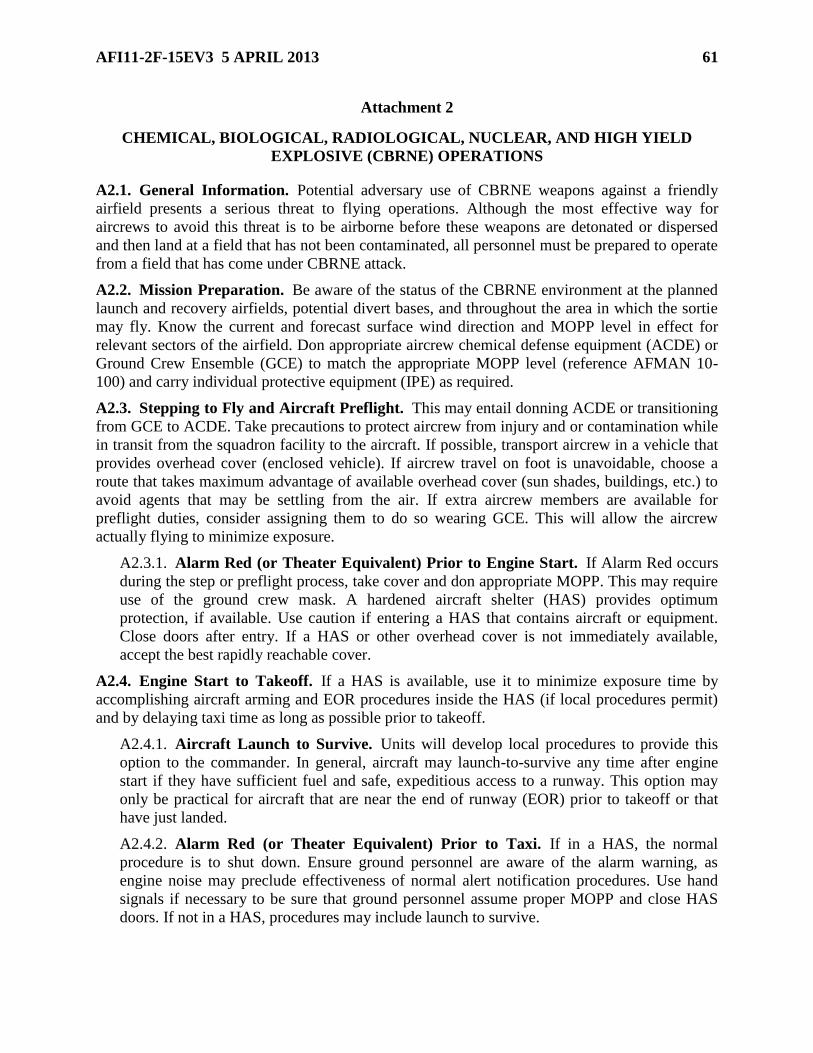
Attachment 2—CHEMICAL, BIOLOGICAL, RADIOLOGICAL, NUCLEAR, AND HIGH
YIELD EXPLOSIVE (CBRNE) OPERATIONS 61
Attachment 3—GENERAL BRIEFING GUIDE 63
Attachment 4—SPECIAL SUBJECT BRIEFING GUIDE (AS APPLICABLE) 65
Attachment 5—ADVANCED HANDLING BRIEFING GUIDE 67
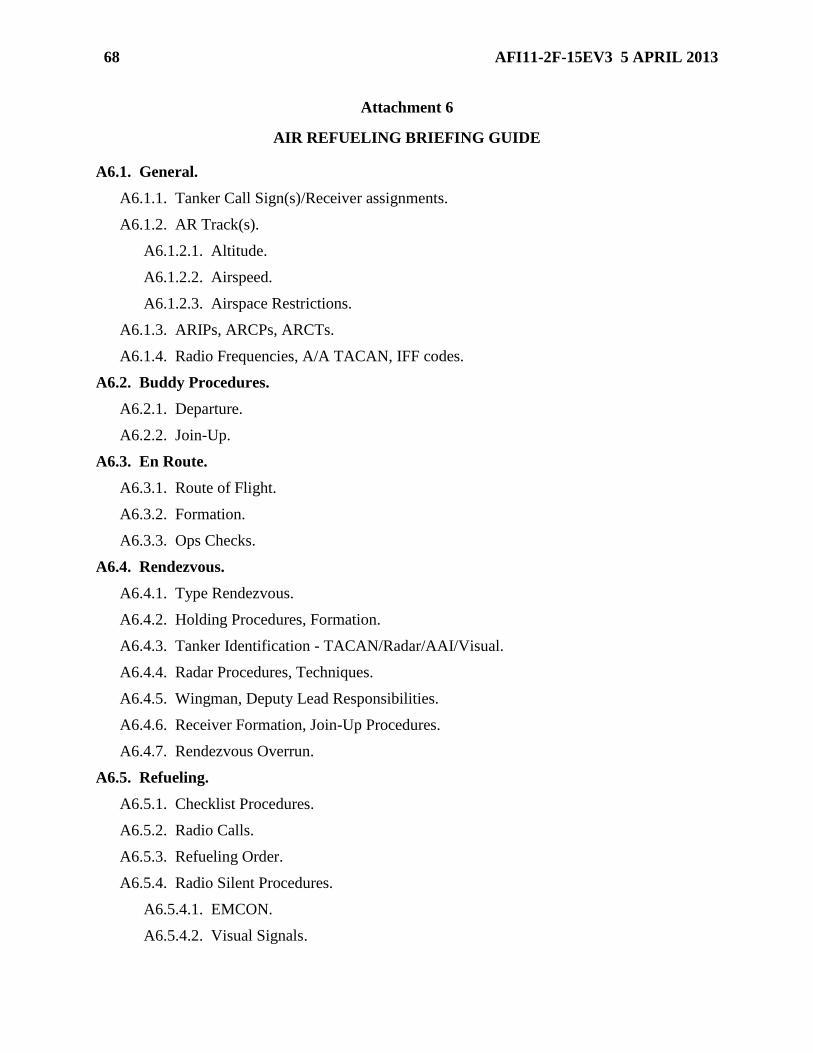
Attachment 6—AIR REFUELING BRIEFING GUIDE 68
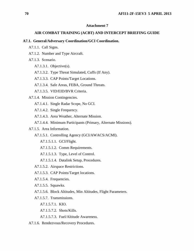
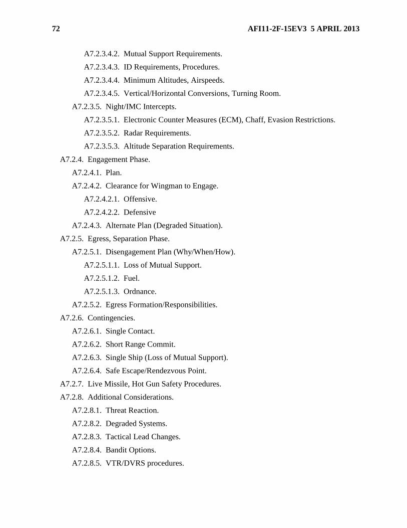
Attachment 7—AIR COMBAT TRAINING (ACBT) AND INTERCEPT BRIEFING
GUIDE 70
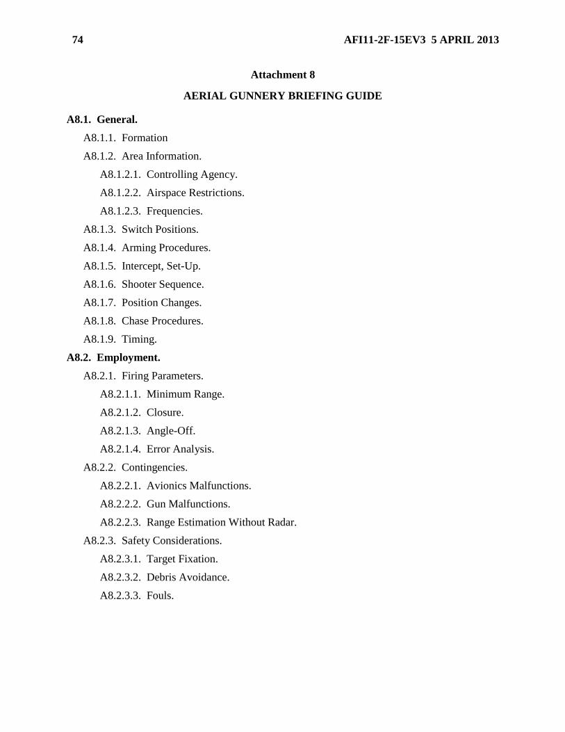
Attachment 8—AERIAL GUNNERY BRIEFING GUIDE 74
Attachment 9—LOW-LEVEL NAVIGATION BRIEFING GUIDE 75
Attachment 10—AIR-TO-SURFACE WEAPONS EMPLOYMENT BRIEFING GUIDE
(RANGE MISSION) 76
Attachment 11—AIR-TO-SURFACE WEAPONS EMPLOYMENT BRIEFING GUIDE
(SURFACE ATTACK TACTICS) 79
Attachment 12—AIR-TO-SURFACE WEAPONS EMPLOYMENT BRIEFING GUIDE
(CLOSE AIR SUPPORT / ARMED RECCE) 82
Attachment 13—ALERT BRIEFING GUIDE 84
Attachment 14—CREW COORDINATION/PASSENGER/GROUND CREW BRIEFING
GUIDE 87
Attachment 15—NIGHT VISION GOGGLE (NVG) BRIEFING GUIDE 88
Attachment 16—MISSION DEBRIEFING GUIDE 90
Page 7
AFI11-2F-15EV3 5 APRIL 2013 7
Chapter 1
GENERAL GUIDANCE
1.1. Abbreviations, Acronyms, and Terms. See Attachment 1.
1.2. Responsibilities. This instruction, in conjunction with other governing directives,
prescribes procedures for operating F-15E aircraft under most circumstances. It is not a substitute
for sound judgment. Procedures not specifically addressed may be accomplished if they enhance
safe and effective mission accomplishment.
1.3. Waivers. Unless another approval authority is cited, waiver authority for this volume is
MAJCOM/A3, or COMAFFOR for those aircrew and assets under a COMAFFOR's oversight.
Waivers are issued for a maximum of one year from the effective date. COMAFFOR will notify
HQ ACC/A3 and home station MAJCOM/A3 of waivers within 72 hours of approval.
1.4. Deviations. In the case of an urgent requirement or aircraft emergency the pilot in
command (PIC) will take appropriate action(s) to safely recover the aircraft. If time permits,
specific approval of the MAJCOM/A3 or COMAFFOR will be obtained for one time deviations
from these procedures.
1.5. Processing Changes.
1.5.1. Submit recommended changes and questions about this publication through
MAJCOM channels to the Office of Primary Responsibility (OPR) per AFI 11-215, USAF
Flight Manuals Program (FMP) using AF Form 847, Recommendation for Change of
Publication.
1.5.2. The submitting MAJCOM will forward information copies of AF Forms 847 to all
other MAJCOMs that use this publication. Using MAJCOMs will forward comments on AF
Forms 847 to the OPR.
1.5.3. OPR will:
1.5.3.1. Coordinate all changes to the basic volume with affected MAJCOM/A3s.
1.5.3.2. Forward change recommendations to AFFSA/A3OF for staffing and AF/A3/5
approval.
Page 8
8 AFI11-2F-15EV3 5 APRIL 2013
Chapter 2
MISSION PLANNING
2.1. Responsibilities. The responsibility for mission planning is shared jointly by all flight
members as well as the Ops and Intel functions in the unit.
2.2. General Procedures.
2.2.1. Planning. Accomplish sufficient flight planning to ensure safe mission execution to
include fuel requirements, map preparation, takeoff and landing data (TOLD), as well as the
lateral asymmetry of the aircraft due to the planned configuration (USAFE: For sorties
landing at other than home-station, reference AFI 11-202V3_USAFESUP_I, Attachment 5,
CONTROL OF FIGHTER AIRCRAFT FOR OFF STATION SORTIES/DIVERT). Consider
foreseeable safety risks and adopt risk mitigation factors in accordance with Operational Risk
Management (ORM).
2.2.2. Standards. The SQ/CC is the approval authority for squadron standards. OG/CC may
publish and approve group or wing standards. Ops Group Stan/Eval (OGV) will review all
standards for compliance with AFI 11-series guidance.
2.3. Unit Developed Checklists and Local Aircrew Aids.
2.3.1. Unit developed checklists may be used in lieu of flight manual checklists (except -25
checklists) provided they contain, as a minimum, all items (verbatim and in order) listed in
the applicable checklist.
2.3.2. Units will produce an aircrew aid that, as a minimum, includes:
2.3.2.1. Briefing guides (reference Briefing Guide Attachments in this volume).
2.3.2.2. Local radio channelization and airfield diagrams.
2.3.2.3. Impoundment procedures, emergency action checklists, and No Radio
(NORDO)/divert information.
2.3.2.4. Arresting gear information for divert bases.
2.3.2.5. Bailout and jettison areas and On-Scene Commander (OSC) checklist.
2.3.2.6. Cross-country procedures to include: command and control, engine
documentation, Joint Oil Analysis Program (JOAP) samples, and aircraft servicing.
2.3.2.7. Other information as deemed necessary by the units (e.g. stereo flight plans,
local training area diagrams, local area maps of sufficient detail to provide situational
awareness on area boundaries).
2.4. Flight Material Preparation.
2.4.1. Mission Data Card. TOLD will be annotated on mission data cards.
2.4.1.1. The minimum TOLD required is maximum abort speed for expected conditions
(i.e. dry/wet/icy), rotation/Nose Wheel Lift Off (NWLO)/takeoff speed, takeoff distance,
single engine rotation/NWLO/SETOS, and normal/heavy weight landing distance for
Page 9
AFI11-2F-15EV3 5 APRIL 2013 9
expected conditions. As applicable, the following speeds will also be annotated: Min Go
when it is equal to or greater than Max Abort; Adjusted Max Abort if used.
2.4.1.2. OG/CC approval is required for operations when Min Go exceeds Max Abort.
Units will provide direction in their local supplements on when Adjusted Max Abort will
be used.
2.4.1.3. The most current version of Technical Orders (TO) 1F-15E-1-1, Flight Manual
Performance Data USAF Series F-15E Aircraft, 1F-15E-1-2-1CL-1 Flight Crew
Checklist USAF Series F-15E Aircraft, and JMPS are the authorized sources for
calculating TOLD.
2.4.1.3.1. Unit developed tabular data must be verified against the TOs and will
include a date and signature block of the aircrew verifying it as correct.
2.4.1.3.2. OPR for certification of TOLD in automated systems is ACC/A8IM. OPR
for revocation of certification due to TO change is ACC/A3TV. Units will be
informed of revocation via MAJCOM Flight Crew Information File (FCIF) message.
2.4.2. Local Area Maps. A separate local area map is not required if the unit aircrew aid
provides a local area map IAW para 2.3.2.7 (USAFE: on flights from a deployed location,
each aircrew will have available a local map annotated with designated flying areas,
emergency airfields, buffer zones, control zones, and restricted or danger areas if this
information is not available in a deploy-location aircrew aid).
2.4.3. Charts. Flight Information Publications (FLIP) en route charts may be used instead
of maps on navigational flights within areas that are adequately covered by these charts.
2.4.4. Low Altitude Maps
2.4.4.1. Reference AFMAN 11-217V2, Chapter 3 for guidance on low-level planning
and map preparation.
2.4.4.2. For all flights conducted in the low-level structure (i.e. below 1,000 feet AGL or
as defined by host nation), each aircraft in the flight will contain a minimum of one Chart
Handbook Manual (CHUM) updated map of the low altitude route or training areas. The
map will be of a scale and quality that terrain features, hazards, and chart annotations are
of sufficient detail to allow navigation and safe mission accomplishment.
2.4.4.3. Highlight all manmade obstacles at or above the planned flight altitude.
2.4.4.4. IAW AFMAN 11-217V2, Chapter 3, annotate all maps with both an Emergency
Route Abort Altitude (ERAA) for the overall route/area and Minimum Safe Altitudes
(MSA) for each leg of the intended route of flight.
2.4.4.4.1. Compute the ERAA (a.k.a. Emergency Safe Altitude [ESA]) IAW
AFMAN 11-217V2, Chapter 3.
2.4.4.4.2. Compute the MSA at a minimum of 1,000 feet above the highest
obstacle/terrain (rounded up to the next 100 feet) within 5NM of the planned course
to include the aircraft turn radius.
2.4.4.5. Terrain Following (TF) Flight Map Preparation. In addition to the low
altitude map requirements listed above:
Page 10
10 AFI11-2F-15EV3 5 APRIL 2013
2.4.4.5.1. Annotate maximum and minimum route structure altitudes if applicable.
2.4.4.5.2. To ensure maps accurately display planned routes, TF turn point bank
angles must reflect realistic systems limitations.
2.4.4.5.3. In order to verify proper operation of the TF system, TF letdown corridors
for the primary (and planned alternate[s], if applicable) entry points for low level
routes will be computed and briefed. As a minimum, compute MSA and Recovery
Initiation Altitude (RIA). Also include values for terrain at 1 NM and command level
off based on the following calculations.
2.4.4.5.3.1. Terrain at 1 NM equates to 2000’ + ½ dive angle x 100'. For
example, using 12° dive and 480 GS, terrain at 1 NM equates to 2600’.
2.4.4.5.3.2. Command level-off begins at 1,000' + ½ dive angle x 100'. For
example, using 12° dive and 480 GS, command level-off begins at 1,600’ AGL
(NLT 1,200 AGL).
2.4.4.5.4. For night TF missions select letdown points that avoid initial descents into
rugged or mountainous terrain (defined by TO 1F-15E-1-2-1, Section 5, as any
vertical change that exceeds 900 ft/NM).
2.4.5. (CONUS Only) Aircrew members flying under VFR or inside MTRs will
supplement existing mission planning materials (e.g. CHUM, FLIP AP/1B, etc.) IAW AFI
11-202V3_ACCSUP, Chapter 2, mission planning requirements.
2.4.6. Aircrew members flying outside CONUS will follow gaining MAJCOM, theater, or
host nation guidance on mission planning (USAFE: reference AFI 11-
202V3_USAFESUP_I, Chapter 2). If no gaining MAJCOM, theater, or host nation guidance
exists, use the best charts or MPS overlay options available to accomplish the above
requirements.
2.5. Fuel Conservation. Design procedures for optimal fuel use and efficiency throughout all
phases of mission execution. Incorporate enroute tasks to maximize use of airborne training
opportunities.
2.6. Preflight Brief.
2.6.1. All flight crewmembers and passengers must attend the flight brief unless previously
coordinated with unit supervisors.
2.6.2. Anyone not attending the flight brief must receive, as a minimum, an overview of
the expected mission flow and events as well as a thorough crew brief that includes potential
emergency procedures (EP). These requirements must be accomplished prior to aircrew step.
2.6.3. Flight leads/instructors are responsible for presenting a logical brief which will
promote safe and effective mission accomplishment.
2.6.3.1. Ensure brief start time provides adequate time to discuss required items and
accounts for mission complexity. As a minimum, begin briefs at least 1.5 hours before
scheduled takeoff. Alert briefs will start in sufficient time to be completed prior to
aircrew changeover.
2.6.3.2. Structure the brief to accommodate the capabilities of each flight member.
Page 11
AFI11-2F-15EV3 5 APRIL 2013 11
2.6.3.3. Ensure contracts, roles, and responsibilities of each flight member are
established, briefed, and debriefed.
2.6.3.4. Include mission priorities, significant rules (e.g. Rules of Engagement [ROE],
Special Instructions [SPINS], Training Rules [TRs]), task management, weather,
NOTAMs, and EPs.
2.6.3.5. Ensure a formation deconfliction, blind, and get well plan for every phase of
flight is briefed and every flight member understands the plan (use para 3.10 as a
baseline). All flight members are responsible for executing this plan.
2.6.3.6. Review TOLD and ensure every member of the flight understands it. Place
particular emphasis on takeoff abort factors during abnormal situations such as short or
wet runway, heavy gross weights, non-standard cable configurations, and abort sequence
in formation flights.
2.6.3.7. Include the following special subjects:
2.6.3.7.1. Radar and visual search responsibilities during departure/enroute/recovery;
2.6.3.7.2. High density traffic areas;
2.6.3.7.3. Mid-air collision avoidance both from other military aircraft as well as
civilian aircraft;
2.6.3.7.4. Lateral Asymmetry considerations (as applicable) to include: takeoff
asymmetry, tactical portions based on planned weapons expenditure, lateral
asymmetry highlight areas (e.g. external tank fuel imbalance combined with high
G/high AOA maneuvering).
2.6.3.8. Include flight responsibilities, proper formation position (to ensure adequate
wingtip clearance), and aircraft-unique requirements for each phase of flight when
dissimilar aircraft or aircraft configurations are flown in the same formation.
2.6.3.9. For missions using Night Vision Goggles (NVG), emphasize proper tuning, use,
and limitations.
2.6.3.10. Low Altitude (i. e. ≤ 5,000 feet AGL) Mission Briefs.
2.6.3.10.1. Emphasize low altitude flight maneuvering, obstacle and ground
avoidance, Low Altitude Warning System (LAWS) and Ground Collision Warning
System (GCWS) features and limitations, low altitude comfort level, and
complacency avoidance.
2.6.3.10.2. For low altitude training over water and featureless terrain, include
specific considerations with emphasis on minimum altitudes and spatial
disorientation.
2.6.3.10.3. For low-level missions using TF, emphasize proper setup as well as both
ground and air checks of the TF system, procedures for transitioning from medium
altitude to low-level TF, and TF maneuvering limitations.
2.6.3.10.4. For low-level missions using TF in conjunction with NVGs, emphasize
the inherent limitations of both systems and the necessary maneuvering restrictions
that each imposes.
Page 12
12 AFI11-2F-15EV3 5 APRIL 2013
2.6.3.11. Alternate Mission Briefs. Brief an appropriate alternate mission for each
flight.
2.6.3.11.1. The alternate mission must be less complex than the primary and should
parallel the primary mission (e.g. Basic Fighter Maneuvers as alternate for Air
Combat Maneuvers, Basic Surface Attack for Surface Attack Tactics, Tactical
Intercepts for Defensive Counter Air).
2.6.3.11.2. If the alternate mission does not parallel the planned mission, brief the
specific mission elements that are different.
2.6.3.11.3. Mission elements may be modified and briefed airborne as long as flight
safety is not compromised. Flight leads will ensure changes are acknowledged by all
flight members.
2.6.3.11.4. Do not fly unbriefed (either on the ground or in the air) missions or
events.
2.6.3.12. Briefing Guides.
2.6.3.12.1. Reference the attachments to this AFI for basic briefing guide examples.
2.6.3.12.2. Subjects may be briefed in any sequence.
2.6.3.12.3. Those items published in AFIs, Air Force Tactics, Techniques, and
Procedures manuals (AFTTP) or unit standards and understood by all participants
may be briefed as “standard.”
2.6.4. Multiple Sortie Days.
2.6.4.1. If all flight members attend an initial or mass flight brief, the flight lead on
subsequent flights need brief only those items that have changed from the previous
flight(s).
2.6.4.2. On multiple-go days when aircraft turn times do not allow follow-on mission
brief(s) and only the initial flight brief is accomplished for all gos, the following guidance
applies (FTU B/TX/SOC/I-course missions may be flown as desired in accordance with
syllabus guidance):
2.6.4.2.1. Upgrade sorties will be flown on the first sortie (second sortie if the first is
non-effective for weather, maintenance, or airspace availability).
2.6.4.2.2. Subsequent sorties missions will be of equal or less complexity with no
additional upgrade training, unless approved by OG/CC.
2.6.4.2.3. Participants in continuation training (CT) missions may fly their primary or
alternate missions in any sequence.
2.7. Postflight Debrief.
2.7.1. All missions will be debriefed.
2.7.2. All flight debriefs will include, at a minimum, the in-flight execution of flight member
responsibilities, deconfliction contracts, tactical employment priorities, and task
management.
Page 13
AFI11-2F-15EV3 5 APRIL 2013 13
Chapter 3
NORMAL OPERATING PROCEDURES
Section 3A—Ground Operations
3.1. Preflight.
3.1.1. Do not carry baggage or equipment in an unoccupied rear cockpit (EXCEPTION:
Forms and maps may be stowed in the map case).
3.1.2. The pilot will brief the ground crew as required. Prior to starting, the pilot will get an
“okay” signal from the rear cockpit occupant. Use operational headsets to the maximum
extent possible during all engine start and pre-taxi checks as well as when technicians are
performing tasks on the aircraft. Hand signals may be used as a last resort or if required
during alert scramble or combat operations.
3.1.3. Unless dictated otherwise by superseding guidance (e.g. COMAFFOR guidance,
theater SPINS, etc.) flying units will set the ejection seat radio beacon selector switch to
AUTO.
3.1.4. Select Pressure Breathing (PBG) as desired. Do not select PBG if using the Aircrew
Eye and Respiratory Protection System (AERPS) or Aircrew Chemical Defense Equipment
(ACDE).
3.1.5. The use of the COMBAT EDGE vest is optional in the F-15E. If aircrew elect to fly
with the COMBAT EDGE vest they will remove the port plug on the CRU-94 (if installed),
properly stow the plug during flight to prevent a FOD hazard, then re-install upon completion
of the sortie.
3.1.6. During the Before Taxi flight control checks, confirm the proper movement and
position of the flight control surfaces with the crew chief.
3.1.7. Minimum Daytime External Lighting. Following is the minimum operational
external lighting during daytime operations. Reference Section 3E Night Procedures for
minimum required nighttime external lighting.
3.1.7.1. All anti-collision lights (reference AFI 11-202V3). EXCEPTION: Reduced or
lights-out operations conducted IAW published guidance or as dictated by real-world
tactical considerations.
3.1.7.2. Landing or taxi light.
3.1.7.3. IAW AFI 11-202V3, position lights are not required between sunrise and sunset,
however they will be used to the maximum extent practical during daytime operations.
3.2. Ground Visual Signals. When ground intercom is not used, use visual signals IAW AFI
11-218, Aircraft Operations and Movements on the Ground and this volume. All signals
pertaining to operation of aircraft systems will originate with the pilot. The crew chief will repeat
the given signals when it is safe to operate the system. Aircrew should not activate any system
that could pose a danger to the ground crew prior to receiving proper acknowledgment from
ground personnel. The following signals augment AFI 11-218.
Page 14
14 AFI11-2F-15EV3 5 APRIL 2013
3.2.1. Jet Fuel Starter (JFS) Start: With clenched fist, pilot makes a pulling motion.
3.2.2. Flight Controls Check: Raise arm, clench fist, and make a stirring motion.
3.2.3. Brake Check: Hold left or right arm horizontal, open hand and push forward,
breaking at the wrist (as in applying rudder pedal pressure with feet).
3.2.4. Digital Electronic Engine Control (DEEC), Improved Digital Electronic Engine
Control (IDEEC)/Asymmetric Thrust Departure Prevention System (ATDPS)
Check: With the fingers and thumb of each hand extended and joined at the tips, open and
close the fingers and thumbs of both hands simultaneously, simulating nozzle opening and
closing.
3.2.5. Target Pod (TGP) Clear: Extend arm and rotate a closed fist in a circular motion.
3.2.6. Loss of Brakes While Taxiing (to the max extent practical regardless if the Emer
Brake/Steer system is successfully engaged): Lower tailhook.
3.3. Taxi and Quick Check/Arming.
3.3.1. The minimum taxi interval is 150 feet staggered or 300 feet in trail. Spacing may be
reduced when holding short of or entering the runway.
3.3.2. Do not taxi during snow or icy conditions until the taxi route and runway have been
checked for safe conditions. In this case, taxi on the centerline with a minimum of 300 feet
spacing. The minimum Runway Condition Reading (RCR) for taxi operations is 10. OG/CCs
may waive this to RCR 8.
3.3.3. Maximum taxi speed during sharp turns (more than 45 degrees of turn) is 10 knots.
Above 10 knots the aircraft may skid or depart the three point attitude.
3.3.4. At non-USAF bases aircrew will make every attempt to coordinate for a rollover/End
of Runway (EOR) inspection with the host maintenance unit.
3.3.5. Keep hands in view of ground personnel during quick check, arming, and de-arming
operations. If the intercom system is not used during EOR checks, the pilot will establish and
maintain visual contact with the ground personnel to allow the use of visual signals.
3.3.6. Do not taxi in front of any aircraft arming or de-arming forward firing ordnance.
3.4. Flight Lineup. Flights will line up as appropriate based on weather, runway conditions,
and runway width.
3.4.1. When separating elements use a minimum of 500 feet spacing between elements.
3.4.2. For formation takeoffs wingmen must maintain wingtip clearance with their element
lead.
3.4.3. If runway width precludes line-up with wingtip clearance between all aircraft in the
flight, use 500 feet spacing between elements or delay run-up until the preceding aircraft or
element releases brakes.
3.5. Before Takeoff Checks. After arming and prior to takeoff all flight members will inspect
each other for proper configuration and any abnormalities.
Section 3B—Takeoff and Departure
Page 15
AFI11-2F-15EV3 5 APRIL 2013 15
3.6. Takeoff.
3.6.1. Do not takeoff if the RCR is less than 12. OG/CCs may waive this to RCR 8.
3.6.2. On training missions, do not takeoff if the computed takeoff roll exceeds 80 percent of
the available runway. For single-ship takeoffs, if the single-ship computed mil-power takeoff
distance exceeds one-half of the available runway, takeoff using afterburner.
3.6.3. When operating from airfields equipped with a compatible, remotely operated cable,
ensure the departure end cable is raised for all takeoffs and landings, unless another departure
end cable is in place.
3.6.4. Use a minimum of 10 seconds (15 seconds when using afterburners) takeoff interval
between aircraft or elements.
3.6.5. Use a minimum of 20 seconds takeoff interval when carrying live air-to-surface
ordnance (N/A for 20mm ammunition) or when performing a trail departure.
3.6.6. Pilots will steer toward the center of the runway at the start of the takeoff roll.
3.6.7. OG/CCs may approve intersection takeoffs.
3.6.8. Do not takeoff over any raised web barrier (e.g. MA-1A, 61QS11) or loose/slack cable
(e.g. BAK-12/13/14).
3.6.9. Suspected Hot Brake Speeds.
3.6.9.1. Unit commanders will ensure Suspected Hot Brake speeds are re-calculated
during Hot Pit or Quick Turn operations using TO 1F-15E-1-2-1CL-1 Brake Energy
Limits Chart.
3.6.9.2. A takeoff abort made when adequate brake cooling time is not met (usually
within one hour of a previous landing) can place the aircraft into the Brake Energy
Caution Zone with brake applications as low as 80 knots (TO 1F-15E-1-2-1, Flight
Manual--F-15E Section 5). Use the following guidance:
3.6.9.2.1. Absorbed energy from landings made one hour or less prior to subsequent
takeoffs will be added in full.
3.6.9.2.2. Use a maximum of 20 million foot-pounds to calculate the abort speed
where suspected hot brakes will be declared.
3.7. Formation Takeoff.
3.7.1. Formation takeoffs are restricted to elements of two aircraft.
3.7.2. Elements must be led by a qualified flight lead unless an Instructor Pilot (IP) is in the
element.
3.7.3. Aircraft must be within 3,000 pounds of each other and symmetrically loaded.
Consider “symmetrically loaded” as no greater than 8,000 ft-lbs of calculated lateral
asymmetry.
3.7.4. Do not make formation takeoffs when:
3.7.4.1. The runway width is less than 125 feet.
Page 16
16 AFI11-2F-15EV3 5 APRIL 2013
3.7.4.2. The Runway Surface Condition (RSC) is reported as wet, or ice, slush, or snow
is on the runway. OG/CCs may waive this requirement if the center 125 feet of the
runway is clear of standing water, ice, slush or snow.
3.7.4.3. The crosswind component exceeds 15 knots.
3.7.4.4. Loaded with live air to ground munitions.
3.7.4.5. Ferrying aircraft from a contractor or Air Logistics Center (ALC) facility.
3.7.4.6. The computed takeoff roll exceeds 50% of the available runway.
3.8. Initial Join-up and Rejoins.
3.8.1. Minimum day weather criteria for a VFR join-up underneath: ceiling 1,500 feet,
visibility 3 SM (5 KM).
3.8.2. Flight leads will maintain TO climb speeds until join-up is accomplished unless
mission requirements necessitate a different airspeed.
3.8.3. Flight leads should limit their angle of bank to 30 degrees for turning rejoins
immediately after takeoff.
3.8.4. For further join-up procedures, see para 3.31 (Night) and para 4.2 (Instruments).
Section 3C—Enroute
3.9. Formation, General. Flight leads/instructors are responsible for ensuring contracts, roles
and responsibilities of each flight member are established and executed.
3.9.1. If any flight member cannot fulfill their basic responsibilities, contracts, or other
assigned tasks, they will immediately communicate that information to the flight or element
lead.
3.9.2. IMC. In IMC the maximum flight size is four aircraft except when flying in close
formation with a tanker (refer to TO 1-F15E-1-2-1, Section VIII Air Refueling Procedures
and Allied Tactical Publication (ATP)-56(B), Air-to-Air Refueling).
3.9.3. Maneuvers. Do not use rolling maneuvers to maintain or regain formation position
below 5,000 feet AGL or outside of SUA (USAFE: Consider SUA as anytime the aircraft is
under Basic, Traffic, or Deconfliction Service).
3.9.4. Signals. Airborne visual signals will be in accordance with AFI 11-205, Aircraft
Cockpit and Formation Flight Signals. For four-ship flights, formation changes will be
initiated by radio call when practical. When formation position changes are directed by radio
all affected wingmen will acknowledge prior to initiating the change. A radio call is
mandatory when directing position changes at night or in IMC.
3.9.5. Recovery. When circumstances permit, flight leads will direct a battle damage (BD)
check after each mission prior to or during Return to Base (RTB). This check is mandatory
following the expenditure of any ordnance (including all types of 20mm ammunition) except
at night or in IMC. Brief deconfliction responsibilities and position change procedures.
Page 17
AFI11-2F-15EV3 5 APRIL 2013 17
3.9.6. Breakups. Flight leads will not break up formations until each wingman has a
positive fix from which to navigate (i.e. visual, Inertial Navigation System [INS], Embedded
GPS/INS [EGI], or Tactical Air Navigation [TACAN])
3.9.7. Changing Leads. Lead changes require a clear transfer of responsibilities from one
flight member to another.
3.9.7.1. Lead changes will be initiated and acknowledged with either a radio call or
visual signal.
3.9.7.2. Ensure deconfliction is established before initiating a lead change.
3.9.7.3. The lead change is effective upon acknowledgment.
3.9.7.4. All flight members must continue to ensure aircraft separation during position
changes.
3.9.7.5. When flying in limited visibility conditions, initiate lead changes from a
stabilized, wings level attitude.
3.9.7.6. The minimum altitude for a lead change is 500 feet AGL over land or 1,000 feet
AGL over water (for night see para 3.32.3, for IMC see para 4.6)
3.9.7.7. When conducting lead changes from fingertip, route, spread, or tactical, do not
initiate lead changes with the wingman further aft than 30 degrees from line abreast.
3.10. Formation Deconfliction.
3.10.1. General. Apply the following rules for flight path deconfliction during tactical
maneuvering:
3.10.1.1. Flight leads will consider wingman/position and ability to safely perform a
maneuver before directing it.
3.10.1.2. Trailing aircraft and elements are responsible for deconfliction from the lead
aircraft and elements. Wingmen and elements will deconflict vertically from the lead/lead
element to the max extent practical. During maneuvering ≤ 1,000 feet AGL, wingmen
and trailing elements will deconflict above the lead/lead element.
3.10.2. Loss of Visual. Use the following procedures when one or more flight members lose
visual contact within the formation or between elements:
3.10.2.1. When any flight member calls "blind", they will initially maneuver away from
the last known position of the other flight member/element (primarily by altering altitude)
and await a response. The appropriate flight member will immediately respond with
"visual" and a position report or "blind".
3.10.2.2. If the other flight member is also "blind", then the flight lead will take action to
ensure altitude separation between flight members and elements.
3.10.2.2.1. The flight lead will specify either AGL or Mean Sea Level (MSL) when
directing the formation to deconflict and use a minimum of 500 feet altitude
separation.
3.10.2.2.2. Avoid climbs or descents through the deconfliction altitude when
possible.
Page 18
18 AFI11-2F-15EV3 5 APRIL 2013
3.10.2.3. If visual contact is still not regained, the flight lead will take additional action
to ensure flight path deconfliction within the flight to include a Terminate/Knock-It-Off
(KIO) call if necessary. The flight lead should consider scenario restrictions such as
sanctuary altitudes and adversary blocks when directing deconfliction.
3.10.2.4. Aircraft will maintain altitude separation until visual and, if necessary, will
navigate with altitude separation until mutual support is regained.
3.10.3. Two-Ship. The following rules apply for flight path deconfliction during tactical
maneuvering of two-ship formations:
3.10.3.1. The wingman is normally responsible for flight path deconfliction.
3.10.3.2. The flight lead becomes responsible for deconfliction when:
3.10.3.2.1. Tactical maneuvering places the lead in the wingman's "blind cone" or
forces the wingman's primary attention away from the lead (i.e. wingman becomes
the engaged fighter).
3.10.3.2.2. The wingman calls “padlocked” or “blind”.
3.10.3.3. Deconfliction responsibility transfers back to the wingman once the wingman
positively acknowledges a visual on his lead (except in cases of tactical maneuvering
where the flight lead is no longer in the wingman’s blind cone).
3.10.4. Three/Four-Ship (or Greater). When flights of more than two aircraft are in
tactical formation:
3.10.4.1. Formation visual signals performed by a flight or element lead pertain only to
the associated element unless specified otherwise by the flight lead.
3.10.4.2. Trailing aircraft and elements will maintain sufficient spacing so that primary
emphasis during formation maneuvering and turns is on low altitude awareness and
deconfliction within elements, not on deconfliction between elements.
3.11. Chase Formation.
3.11.1. Restrictions. Any pilot may fly safety chase for aircraft with a problem or under
emergency conditions.
3.11.1.1. Pilots who have successfully completed an Instrument and Qualification
evaluation may chase as safety observer for aircraft performing simulated instrument
flight or hung ordnance patterns.
3.11.1.2. Specialized missions (i.e., Operational Test and Evaluation (OT&E), Weapon
Systems Evaluation Program (WSEP), live weapons delivery, etc.) and training
conducted IAW AFI 11-2F-15EV1 may be chased by Combat Mission Ready
(CMR)/Basic Mission Capable (BMC) pilots designated by group or squadron
commanders.
3.11.1.3. All other chase events may only be flown by an IP, Stan/Eval Flight Examiner
(SEFE), or upgrading IP (UIP) under the supervision of an IP.
3.11.2. Procedures.
Page 19
AFI11-2F-15EV3 5 APRIL 2013 19
3.11.2.1. A safety observer in a chase aircraft, except IP/SEFE/specialized mission
chase, will maneuver in a 30-60 degree cone and maintain nose/tail separation to
effectively clear and provide assistance.
3.11.2.2. IP/SEFE/specialized mission aircraft will maneuver as necessary, but must
maintain nose/tail separation.
3.11.2.3. No chase aircraft will stack lower than the lead aircraft when below 1,000 feet
AGL.
3.11.2.4. For live ordnance missions, the chase pilot is responsible for maintaining own
ship frag deconfliction.
3.12. Show Formation. Refer to AFI 11-209, Aerial Event Policy and Procedures and
applicable MAJCOM directives for specific rules and appropriate approval levels to participate
in static displays and aerial events.
3.13. Maneuvering Parameters.
3.13.1. If flight through wingtip vortices or jetwash is unavoidable or inadvertently
encountered, immediately unload the aircraft to approximately 1 G.
3.13.2. Do not extend flaps during Air Combat Training (ACBT).
3.13.3. Minimum Altitudes.
3.13.3.1. Nose high, low speed recoveries and Aircraft Handling Characteristics (AHC)
vertical maneuvers: 10,000 feet AGL.
3.13.3.2. Aerobatics: 5,000 feet AGL.
3.13.4. Authorized speeds. (US NAS) Below 10,000 feet MSL (outside SUA or MTRs) fly
no faster than the maneuvering airspeeds as published in TO 1F-15E-1-2-1 (e.g. 300 - 350
KCAS unless in the radar pattern). In order to aid adherence to this guidance, flight leads and
aircrew will comply with the following:
3.13.4.1. (US NAS) Accomplish systems checks and TF checks above 10,000 feet MSL
to the maximum extent possible. If TF checks must be accomplished below 10,000 feet
MSL (i.e. due to weather) aircrew will minimize the time at higher airspeeds.
3.13.4.2. Aircrew flying outside the US NAS will follow gaining MAJCOM, theater, or
host nation guidance on airspeeds (USAFE: Aircrew will operate at airspeeds consistent
with TO 1F-15E-1-2-1, AFTTP 3-3.F-15E, and local guidance). If no gaining MAJCOM,
theater or host nation guidance exists, use the guidance in this instruction to the
maximum extent practical.
3.14. G-Awareness Exercise.
3.14.1. G-awareness exercises will be accomplished IAW AFI 11-214, Air Operations Rules
and Procedures. The Heads Up Display (HUD) will be recorded during G-awareness
exercises with hot mic in both cockpits.
3.14.2. During maneuver execution use visual lookout and briefed formation contracts as
primary means to ensure aircraft deconfliction. Use onboard systems (i.e. FDL) only as an
aid to situational awareness.
Page 20
20 AFI11-2F-15EV3 5 APRIL 2013
3.14.3. Do not use G-awareness turns for systems checks or other items that detract from the
intended purpose.
3.14.4. Flight leads will ensure the airspace intended for conducting the G-awareness
exercise is free from potential traffic conflicts. Use Air Traffic Control (ATC) services to the
maximum extent practical to aid in clearing the airspace. Conduct the G-awareness exercise
in the following airspace with preference to the order as listed (USAFE: Consider SUA as
anytime the aircraft is under Basic, Traffic, or Deconfliction Service):
3.14.4.1. SUA (e.g. Restricted or Warning areas, ATC Assigned Airspace [ATCAA],
Military Operating Areas [MOA], or MAJCOM-approved large-scale exercise and
special mission areas).
3.14.4.2. Above 10,000 feet MSL outside of SUA.
3.14.4.3. Inside the confines of MTRs and above 5,000 feet AGL.
3.14.4.4. Below 10,000 feet MSL outside of SUA.
3.15. Radio Procedures.
3.15.1. Any flight member may make a "Knock-It-Off" or "Terminate" call IAW AFI 11-
214. A KIO applies to any phase of flight and any type of mission.
3.15.2. Wingman acknowledgment of flight lead radio calls indicate the wingman
understands or that the appropriate action is complete or in the process of being completed.
3.15.3. In addition to the radio procedures outlined in AFI 11-202V3, AFMAN 11-217V1
and V2, Instrument Flight Procedures, and FLIP publications, the following radio
transmissions are required:
3.15.3.1. All flight members will acknowledge understanding the initial ATC clearance.
Acknowledge subsequent ATC instructions as directed by the flight lead.
3.15.3.2. Gear Checks. Each pilot will confirm configuration with crewmate and report
gear down IAW the following guidance, but in no case later than crossing the runway
threshold IAW AFI 11-202V3:
3.15.3.2.1. Base turn for overhead patterns.
3.15.3.2.2. Prior to 3NM final for VFR straight-in.
3.15.3.2.3. Final Approach Fix (FAF) or glide slope intercept for instrument
approaches.
3.15.3.2.4. A wingman or chase ship need not make this call during a formation or
chased approach.
3.16. Air Refueling (AAR). Reference TO 1F-15E-1-2-1, Section VIII Air Refueling
Procedures and Allied Tactical Publication (ATP)-56(B), Air-to-Air Refueling. During AAR
training that involves unqualified student pilots (i.e., “UP” enrolled in a formal IQT course and
under the direct supervision of an IP), it is the responsibility of the Flight Lead or IP to inform
the tanker that unqualified student training will be conducted.
3.16.1. This applies any time prior to the student pilot successfully completing his/her initial
(INIT) or requalification (RQ) INSTM/QUAL evaluation
Page 21
AFI11-2F-15EV3 5 APRIL 2013 21
3.16.2. This also applies prior to the student pilot demonstrating proficiency in AR
operations or prior to regaining proficiency if regression occurs even if an INIT/RQ
INSTM/QUAL evaluation was successfully completed. Day and night demonstration of
proficiency shall be considered two different events.
3.16.3. Regardless of qualified status, pilots will inform boom operators when refueling
from a particular type tanker for the first time.
3.17. Low Altitude (≤ 5,000 feet AGL) Procedures.
3.17.1. Formation. Line abreast formation is only authorized at or above 300 feet AGL.
When flying below 300 feet AGL flight leads shall direct the wingman to a wedge formation
position.
3.17.2. Terrain and Obstacle Clearance.
3.17.2.1. All obstacle avoidance planning will be based on MSA and ERAA as defined
in para 2.4.4, AFI 11-202V3, Chapter 8, and AFMAN 11-217V2, Chapter 3.
3.17.2.2. If unable to visually acquire or ensure lateral separation from known obstacles
that could be a factor to the flight, flight leads will direct a climb not later than 3 NM
prior to ensure sufficient vertical separation IAW with AFMAN 11-217V2. Do not
descend back into the low level environment until visual with the obstacle or positional
awareness dictates it is safe to do so.
3.17.2.3. During all descents into and operations in the low-level environment (i.e. ≤
1,000 feet AGL) the LAWS will be set at 90 percent of the briefed minimum altitude or
90 percent of the command-directed minimum altitude, whichever is higher.
3.17.2.4. During all operations in the low-level environment, the immediate reaction to
task saturation, diverted attention, KIOs, or emergencies is to climb to 1,000 feet AGL or
higher if during the day, MSA or ERAA if at night.
3.17.3. Maneuvering. When crossing high or hilly terrain, maintain positive G and do not
exceed 120 degrees of bank. Maneuvering at less than 1G is limited to upright bunting
maneuvers only.
3.17.4. Minimum Airspeed. The minimum airspeed for low level (less than 1,000 feet
AGL) navigation is 300 KCAS. Minimum airspeed for tactical maneuvering in a LOWAT
environment is 350 KCAS (except during LOFT recoveries).
3.17.5. Minimum Weather. The minimum WX for visual low level training is 1,500 feet
ceiling and 3SM visibility (USAFE: 1,500 feet/8KM) or as specified in FLIP for MTRs, unit
regulations, or national rules, whichever is higher.
3.17.6. Minimum Altitude.
3.17.6.1. 500 feet AGL for Low Altitude Training (LOWAT) Category I qualified
aircrew.
3.17.6.2. 300 feet AGL for LOWAT Category II qualified aircrews and F-15E Formal
Training Unit (FTU) students with instructors when conducting training IAW an
applicable syllabus.
Page 22
22 AFI11-2F-15EV3 5 APRIL 2013
3.17.6.3. 100 feet AGL for LOWAT Category III qualified aircrews. Training in the 100
feet to 300 feet AGL altitude block will be in short segments consistent with real-world
risks and realistic tactical considerations.
3.17.6.4. During contingency operations, all low altitude (≤ 5,000 feet AGL) tactical
maneuvers not associated with an actual target attack or threat reaction and accomplished
in support of ground forces (e.g. “Show of Force”) will be flown at or above aircrew
LOWAT minimum.
3.17.6.5. For night operations the minimum altitude is MSA unless operating under the
conditions of para 3.18 (TF Operations) and/or para 3.34 (Night Vision Goggles
Procedures).
3.17.6.6. For over water operation the minimum altitude is 1,000 feet above the surface
unless in sight of land or using TF flyup protection. If in sight of land or using TF flyup
protection the minimum altitude may be lowered to at or above aircrew LOWAT
minimum.
3.17.6.7. For Air to Surface range operations, minimum altitudes will be determined by
specific range guidance, AFI 11-2F-15EV1, or AFI 11-214, whichever is higher.
3.17.7. Entries/Descents into the Low Altitude (≤ 5,000 feet AGL)
structure. Accomplish entry/descent into the low altitude structure or training area under an
ATC radar service (e.g. flight following or host nation equivalent) to the maximum extent
practical.
3.17.8. Visual Meteorological Conditions (VMC) Route and Area Abort Procedures.
3.17.8.1. Maintain safe separation from the terrain and other aircraft.
3.17.8.2. Comply with VFR altitude and national airspace restrictions. Squawk
applicable IFF modes and codes.
3.17.8.3. Maintain VMC at all times. If unable, follow IMC procedures outlined below.
3.17.8.4. Attempt contact with controlling agency, if required.
3.17.9. IMC Route and Area Abort Procedures.
3.17.9.1. Immediately climb to (or above) the briefed ERAA.
3.17.9.2. Maintain preplanned ground track. Execute appropriate lost wingman
procedures if necessary.
3.17.9.3. Squawk emergency if deviations from normal route or area procedures are
required, or if the ERAA or MSA is higher than the vertical limits of the route or area.
3.17.9.4. Attempt contact with the appropriate ATC agency for an IFR clearance. If
required to fly in IMC without an IFR clearance, cruise at appropriate VFR altitudes until
IFR clearance is received.
3.17.10. Low Altitude Target Pod (TGP) Use. The TGP may be used down to the PIC’s
LOWAT category minimum unless under direct supervision of an instructor (either in the
aircraft or in chase) on a syllabus ride leading to a lower LOWAT category minimum. This
Page 23
AFI11-2F-15EV3 5 APRIL 2013 23
guidance also applies to use of the LASER if not restricted to a higher altitude by specific
SUA guidance, weapons delivery minimums, or host nation rules (if outside the US NAS).
3.18. General TF System Operations. (Also see para 3.33 for night TF requirements).
3.18.1. The minimum altitude for TF training will be the higher of MTR minimum altitude,
MOA floor, or aircrew LOWAT category.
3.18.2. Unarmed TF operations are prohibited.
3.18.3. The pilot will maintain 400 KCAS minimum airspeed in mountainous terrain
(defined by TO 1F-15E-1-2-1, Section 5, as any vertical change that exceeds 900 ft/NM).
3.18.4. In addition to a fully functioning TF system, a properly functioning A/A and A/G
radar are required for IMC TF.
3.18.5. Check TF systems in flight using TO 1F-15E-1-2-1, Chapter 2, procedures prior to
TF operations. If any feature critical to overall system performance (e.g. RALT, INS) is
questionable or disabled and cannot be fixed IAW TO 1F-15E-1-2-1CL-1 or TO 1F-15E-34-
1-1CL-1, discontinue the TF portion of the mission.
3.18.6. Each aircrew will confirm with their crewmate that the TF and RALT are on and
working properly before descending below the MSA.
3.18.7. Initially set a 1,000 feet AGL Set Clearance Plane (SCP) to verify proper systems
operation prior to commencing letdown to a lower SCP.
3.18.8. During operations in the low-level environment conducted solely on TF, the pilot
will not operate any heads down sensor while outside of TF system limits. Sole attention will
be placed on re-establishing aircraft parameters within TF limits.
3.18.9. Any intentional maneuvering that will put the aircraft outside of TF limits will be at
or above the MSA (or ERAA if not within 5NM of course) or within the restrictions of para
3.34 NVG Procedures.
3.18.10. Abnormal Operation during IMC TF. Aircrews who experience failure of any
portion of the TF system or A/A / A/G radar while flying IMC TF will immediately climb to
(or above) the MSA (or ERAA if not within 5NM of course).
3.18.10.1. If the failure(s) can be cleared and safe TF regained, TF operations may
resume.
3.18.10.2. If the aircraft position cannot be accurately determined, aircrews will
terminate the low level portion of the mission and execute route abort procedures IAW
para 3.17.9
3.19. Fuel Requirements.
3.19.1. Joker / Bingo Fuel. As defined in AFI 11-214
3.19.2. Normal Recovery Fuel. The fuel on initial or at the FAF at the base of intended
landing or alternate, if required. Fuel quantity will be as established locally or 2,500 pounds,
whichever is higher.
Page 24
24 AFI11-2F-15EV3 5 APRIL 2013
3.19.3. Minimum and Emergency Fuel. Declare the following to the applicable ATC
agency when it becomes apparent that an aircraft may land at the intended destination or
alternate, if required, with:
3.19.3.1. Minimum Fuel. 1,900 pounds or less.
3.19.3.2. Emergency Fuel. 800 pounds or less.
Section 3D—Recovery and Landing
3.20. Overhead Traffic Patterns.
3.20.1. Overhead patterns may be flown with unexpended A/G practice ordnance (to include
inert heavyweight), live air-to-air missiles, and any 20mm ammunition. Overhead patterns
may be performed at deployed locations with unexpended live ordnance if required by local
force protection arrival procedures or approved by the owning OG/CC.
3.20.2. Initiate the break IAW local procedures or as directed by ATC.
3.20.3. Execute individual breaks at minimum interval of 5 seconds (except IP/SEFE chase
or when in tactical formation).
3.20.4. Aircraft must be wings level on final at approximately 300 feet AGL and 1 mile from
the planned touchdown point.
3.21. Tactical Overhead Traffic Patterns. Tactical entry to the overhead traffic pattern is
permitted when:
3.21.1. Executed IAW local ATC procedures.
3.21.2. No more than four aircraft are in the flight.
3.21.3. No aircraft are offset from the runway in the direction of the break. The intent is to
avoid requiring a tighter than normal turn to arrive on normal downwind.
3.21.4. Downwind, base turn, and formation spacing are flown such that aggressive or
abnormal pattern corrections are not required.
3.22. Low Approaches.
3.22.1. Minimum Altitudes.
3.22.1.1. Normal and no-flap single ship low approaches: So that touchdown does not
occur.
3.22.1.2. Practice single-engine go-around: Initiate in sufficient time to ensure the
aircraft does not descend below 300 feet AGL.
3.22.1.3. IP/SEFEs flying chase position: 50 feet AGL.
3.22.1.4. Formation low approaches and non-IP/SEFE chase: 100 feet AGL.
3.22.1.5. Chase aircraft during an emergency: 300 feet AGL unless safety or
circumstances dictate otherwise.
Page 25
AFI11-2F-15EV3 5 APRIL 2013 25
3.22.2. Go-Around. Unless local ATC procedures, missed approach/climb-out procedures,
or ATC instructions dictate otherwise, remain no higher than 500 feet below VFR overhead
traffic pattern altitude until crossing the departure end of the runway.
3.23. Landing.
3.23.1. The desired touchdown point is 500-1,000 feet past the runway threshold for a VFR
pattern or non-precision approach, or 500-1,000 feet past the Runway Point of Intercept
(RPI) for a precision approach.
3.23.2. Minimum touchdown spacing is IAW AFI 11-202V3, Chapter 5 as supplemented by
MAJCOM. F-15A-D and foreign variants are similar fighter type aircraft to the F-15E.
Increase spacing whenever wake turbulence or jetwash could be a factor.
3.23.3. Normally, all aircraft will land in the center of the runway and clear to the cold
(turnoff) side of the runway when speed and conditions permit.
3.23.4. Landing Restrictions.
3.23.4.1. When the computed landing roll exceeds 80 percent of the available runway,
land at an alternate if possible.
3.23.4.2. Do not land over any raised web barrier (e.g. MA-1A, 61QS11), or loose or
slack cable (e.g. BAK-12/13/14)
3.23.4.3. During the aerobrake portion of a normal, dry runway landing, leave flaps
down to provide increased aerodynamic drag and normal nose fall.
3.23.4.4. When the RCR at the base of intended landing is less than 12, land at an
alternate if possible. If an alternate is not available, an approach end or mid-field
arrestment is recommended.
3.24. Touch-and-Go Landings. Fly touch-and-go landings IAW AFI 11-202V3, as
supplemented by MAJCOM. Do not fly touch-and-go landings with any of the following:
3.24.1. Live A/A or A/G ordnance (exception: any 20mm ammunition).
3.24.2. Hung ordnance or gun malfunction of any kind.
3.24.3. Fuel remaining in any external tank.
3.25. Closed Traffic Patterns.
3.25.1. Initiate the pattern at the departure end of the runway unless directed otherwise by
local procedures or ATC.
3.25.2. If executing a formation low approach, a sequential closed may be flown with ATC
concurrence.
3.25.3. Plan to arrive on downwind at 200-250 KCAS.
3.26. Back Seat Approaches and Landings. During back seat approaches and landings, the
front seat pilot will visually clear the area, monitor aircraft parameters and configurations, and be
prepared to direct a go-around or take control of the aircraft (as briefed by the rear cockpit pilot)
if necessary.
3.27. Formation Approaches.
Page 26
26 AFI11-2F-15EV3 5 APRIL 2013
3.27.1. Do not practice formation approaches with a combined fuel and stores weight greater
than 10,000 pounds (N/A for SEFE Chase). Aircraft must be within 3,000 pounds of each
other and symmetrically loaded. Consider “symmetrically loaded” as no greater than 8,000
ft-lbs of calculated lateral asymmetry.
3.27.2. Minimum weather for formation approaches is 500 feet ceiling and 1.5 SM (2.4
KM) or the highest Pilot Weather Category (PWC) in the flight, whichever is higher
(exception: an actual emergency requiring a formation landing).
3.28. After Shutdown Procedures. All flight members will accomplish a post flight walk-
around. The intent of this inspection is to find evidence of birdstrike, lost panels, damaged
ordnance, structural damage resulting from over-Gs, or other in-flight abnormalities.
Section 3E—Night Procedures
3.29. Night Ground Operations.
3.29.1. When ground personnel are working under the aircraft, the anti-collision lights
should be OFF and the position lights ON and not flashing.
3.29.2. Taxi with a minimum of 300 feet spacing.
3.29.3. Use the taxi light while taxiing unless it might interfere with an aircraft landing or
taking off. The taxiing aircraft will come to a stop if the area cannot be visually cleared
without the taxi light.
3.29.4. Minimum required operational exterior lighting for night flying operations is:
landing and taxi light, both wing-root anti-collision lights, both wingtip position lights, and
the Right Vertical Stab (RVS) anti-collision light. Substituting a formation light in lieu of a
wingtip position light is not permitted. EXCEPTION: Reduced or lights-out operations
conducted IAW published guidance or as dictated by real-world tactical considerations.
3.30. Night Takeoff.
3.30.1. During a night formation takeoff, direct brake release and configuration changes on
the radio.
3.30.2. Following takeoff, each aircraft and element will climb on runway heading to 1,000
feet AGL before initiating turns unless directed otherwise by ATC or local procedures.
3.31. Night Join-Up.
3.31.1. Weather criteria for night join-up underneath a ceiling is a minimum 3,000 feet
ceiling and 5 SM (8 KM) visibility.
3.31.2. After join-up, turn the anti-collision lights OFF except for the last aircraft in
formation. The last aircraft will keep the anti-collision lights ON unless otherwise directed
by the flight lead.
3.32. Night Formation Procedures.
3.32.1. When in trail formation, whether IMC or VMC, use all available aircraft systems to
maintain aircraft spacing backed up with timing. If aircraft spacing cannot be ensured, then
establish altitude separation (1,000 feet minimum).
Page 27
AFI11-2F-15EV3 5 APRIL 2013 27
3.32.2. To preclude incidents of Spatial Disorientation as well as ensure proper ground
clearance at all time, aircrew will not depend solely on HUD information and ensure they are
using a consistent instrument cross-check to include periodic use of an EADI.
3.32.3. Except in case of emergency, do not direct lead or formation changes below 1,500
feet AGL unless on radar downwind. Above 1,500 feet AGL, direct lead or formation
changes using the radio and from a stabilized, wings-level attitude.
3.32.4. Prior to a formation break-up at night, the flight lead will transmit attitude, altitude,
airspeed, and altimeter setting, which will be confirmed and acknowledged with “good
NAVAIDs” by the flight.
3.32.5. Battle damage checks will not be performed at night without NVGs (see para 3.34.6).
3.33. Night TF Operations.
3.33.1. A fully functioning TF system is required to conduct night TF operations (VMC or
IMC). In addition to the minimum equipment listed in para 3.18.5, a usable
Navigation/Forward Looking Infrared (NAV/FLIR) HUD image is required. NVGs may be
used in place of the NAV/FLIR.
3.33.2. TF failure prior to low-level route entry: If the TF system fails prior to route entry,
aircrew may still enter the route and continue the mission either at the MSA (or ERAA if
greater than 5NM from course) or by using NVG procedures IAW para 3.34.
3.33.3. TF failure while in the low-level environment: Aircrews who experience failure of
any portion of the TF system or NAV/FLIR imagery (or NVGs if used in place of the
NAV/FLIR) while flying night TF low level will immediately climb to (or above) the MSA
(or ERAA if not within 5NM of course) or transition to NVG procedures IAW para 3.34.
3.33.4. Climb to MSA (or ERAA if not within 5NM of course) when NAV/FLIR
transmissivity or NVG visibility (if NVG is used in place of the NAV/FLIR) is insufficient
for use as an aid for terrain avoidance (N/A for IMC TF qualified crews and supervised
crews in an IMC TF upgrade using IMC procedures).
3.34. NVG Procedures.
3.34.1. NVGs must be preflight tested and adjusted by the individual in the unit eyelane
prior to NVG operations.
3.34.2. General NVG Use.
3.34.2.1. NVGs must be off and secured during takeoff and landing.
3.34.2.2. Do not don NVGs until at least 2,000 feet AGL in climbing or level flight.
3.34.2.3. Remove NVGs prior to initial, the FAF, or glide slope intercept.
3.34.2.4. Flight members will communicate when donning or doffing NVGs. Only one
crewmember per aircraft will don or doff NVGs at a time.
3.34.3. NVGs will not be worn in IMC.
3.34.4. Wingmen will fly no closer than NVG close formation (as defined in AFTTP 3-3.F-
15E Chap 8).
Page 28
28 AFI11-2F-15EV3 5 APRIL 2013
3.34.5. NVGs may be worn for tanker rejoins, but will be raised to the up and locked
position or removed and stowed no later than the pre-contact position.
3.34.6. Night BD Checks.
3.34.6.1. Night BD checks are permitted only when wearing NVGs.
3.34.6.2. The crew performing the BD check will approach with position lights bright
and steady and beacons on while the aircraft being checked sets external lights to a
minimum (with at least anti-collision beacons off).
3.34.7. NVG Abnormal Procedures.
3.34.7.1. During in-flight emergencies, immediately assess whether the NVGs aid or
hinder completion of emergency procedures. If they are a hindrance or the emergency
may deteriorate into an ejection situation, remove and stow the NVGs.
3.34.7.2. For NVG failure or inadvertent flight into IMC while in formation or close
proximity to other aircraft:
3.34.7.2.1. Immediately transition to instruments (see para 4.1.1).
3.34.7.2.2. Perform appropriate lost wingman procedures if applicable.
3.34.7.2.3. Terminate or KIO as appropriate.
3.34.7.2.4. Move NVGs to the up and locked position or remove and stow
completely if practical.
3.34.7.2.5. Maintain or regain VMC as soon as possible.
3.34.7.3. For NVG failure while in the low-level environment, ensure separation from
other aircraft and climb to (or above) MSA (or ERAA if not within 5 miles of course)
prior to troubleshooting.
3.34.7.4. For inadvertent flight into IMC while in the low-level environment, follow
IMC route abort procedures in para 3.17.9.
3.35. Night Landing.
3.35.1. Normally land from an instrument straight-in approach. Refer to AFI 11-202V3,
Chap 5, night approaches, as supplemented, for specific procedures.
3.35.2. Only perform night formation landings when required for safe recovery of the
aircraft.
Section 3F—Miscellaneous Procedures
3.36. Change of Aircraft Control. Both aircrew members must know at all times who has
control of the aircraft. Use the statement "you have the aircraft" to transfer aircraft control. The
aircrew member receiving control of the aircraft will acknowledge "I have the aircraft" and
lightly shake the stick. Once assuming control of the aircraft, maintain control until relinquishing
it as stated above. EXCEPTION: If the intercom fails, the crewmember not flying the aircraft
who intends to assume control of the aircraft will lightly shake the stick and assume control of
both the aircraft and radios unless otherwise prebriefed (i.e. “shake to take”). With intercom out,
Page 29
AFI11-2F-15EV3 5 APRIL 2013 29
if either crewmember who is in control of the aircraft intends for the other crewmember to
assume control, they will lightly push the rudder pedals back and forth (i.e. “push to pass”).
3.37. Ops Checks.
3.37.1. Accomplish sufficient ops checks to ensure safe mission accomplishment. Each
aircrew should monitor the fuel system carefully throughout the flight to identify low or
trapped fuel or imbalance situations as soon as possible. Ops checks are required:
3.37.1.1. After takeoff during initial climbout (to the max extent practical when passing
10,000 feet) and at level-off.
3.37.1.2. A/A. Prior to each ACBT engagement or intercept. In addition, a check for
proper operation of all transfer tanks (wing tanks balanced and tank 1 feeding) will be
performed prior to and between engagements or planned maneuvering above 30 CPU
Angle of Attack (AOA).
3.37.1.3. A/G. Prior to entering an A/G range and at least once after departing the range
(at least once on range if multiple passes are flown).
3.37.1.4. Following Air Refueling.
3.37.2. Minimum Ops Check items are engine instruments, total and internal fuel quantities
and balance (as well as external fuel quantities and balance, if loaded), G-suit connection,
oxygen system, cabin altitude, and Overload Warning System (OWS).
3.37.3. In formation flights, the flight lead may initiate ops checks by radio call or visual
signal and wingmen will respond appropriately. The query and response for ops checks will
include the following:
3.37.3.1. Pointer over counter readings (e.g. "13 over 25, externals" or "13 over 18,
CFTs").
3.37.3.2. Following external wing tank and CFT fuel consumption, ensure tank one is
feeding correctly; add a "balanced" call to the normal Ops Check reply when wing tank
fuel balance checks are required and the difference is no greater than 200 lbs. (e.g. "8
squared, balanced, tank 1") (EXCEPTION: Total fuel only may periodically be used
during high demand phases of flight).
3.37.4. Fighter Data Link (FDL) fuel status will not be used as the primary source of fuel
checks.
3.38. F-15E Crew Duties. Both crewmembers are responsible for successful sortie completion.
A crew brief will be accomplished before each flight to ensure an understanding of all aspects of
the mission.
3.38.1. The crew brief will include radar and visual lookout responsibilities, crew
coordination, and specific duties for each phase of flight. For night sorties, the crew brief will
include expected crew coordination for deviations from planned/expected flight parameters.
Aircrew will reference AFTTPs 3-3.F15E and 3-1.F-15E for a thorough discussion of
standardized F-15E crew responsibilities and coordination.
Page 30
30 AFI11-2F-15EV3 5 APRIL 2013
3.38.2. Below 10,000’ feet MSL, crew members will limit crew interaction and cockpit tasks
only to those necessary either for tactical training/employment or safe recovery of the aircraft
(to include radio drills).
3.38.3. Unless briefed otherwise, the following duties apply. (EXCEPTION: The restrictions
listed in para 3.38.3.1 may not be altered.)
3.38.3.1. Weapon Systems Officer (WSO) Flying. WSOs will not fly during:
3.38.3.1.1. Takeoff or landing.
3.38.3.1.2. AAR operations.
3.38.3.1.3. Close formation or rejoins to close formation.
3.38.3.1.4. Tactical maneuvering. EXCEPTION: During FTU syllabus missions,
student WSOs may practice flying tactical formation turns and position keeping if
accompanied by an IP.
3.38.3.1.5. Weapons delivery (actual or simulated).
3.38.3.1.6. Below 1,000 feet AGL (unless flying practice instrument approaches and
no lower than non-precision approach minimums, the pilot's weather category, or 500
feet AGL, whichever is higher).
3.38.3.1.7. Overhead patterns
3.38.3.2. Takeoff. The WSO will check the Min go/Max abort speed when required,
monitor engine and flight instruments, check gear and flaps up prior to their TO speed
limits, and advise the pilot of any discrepancies.
3.38.3.3. Climb/Departure. The aircrew member flying the aircraft will call altimeter
setting to 29.92 when passing the transition altitude.
3.38.3.4. Cruise, Navigation, and Instrument Flight. The WSO will relay aircraft
attitude, altitude, and airspeed information to the pilot when departing a formation at
night or in IMC.
3.38.3.5. Air Refueling.
3.38.3.5.1. Pilot Responsibilities. Be prepared to immediately use the air refueling
release HOTAS if an IP/UIP in the RCP is accomplishing the refueling and either the
RCP air refueling release button on the stick doesn’t work or safety dictates.
3.38.3.5.2. WSO Responsibilities. Advise the pilot of boom position and call when
boom is positively disconnected and clear.
3.38.3.6. Instrument Penetrations and Descents.
3.38.3.6.1. The aircrew member in control of the aircraft will advise the other
crewmember of intentions when performing any penetration or approach.
3.38.3.6.2. Both crewmembers must confirm the Decision Height (DH)/Decision
Altitude (DA) or Minimum Descent Altitude (MDA) for an approach, or the ERAA
and MSA altitudes for descents into the low-level environment.
Page 31
AFI11-2F-15EV3 5 APRIL 2013 31
3.38.3.6.3. Both crewmembers will refer to appropriate FLIP publications during the
holding, penetration and approach.
3.38.3.6.4. The crewmember not in control of the aircraft will verbally check
altimeter settings when passing the transition level.
3.38.3.6.5. The crewmember not in control of the aircraft will advise the other
crewmember when 1,000 feet above any intermediate level off altitude, 100 feet
above DH/DA or MDA for the approach being flown, or when 1,000 feet above the
minimum altitude during descents into the low-level environment.
3.38.3.7. Pattern and Landing. The crewmember not in control of the aircraft will:
3.38.3.7.1. Monitor the pattern with emphasis on engine power, altitude, airspeed,
landing gear, and flap position.
3.38.3.7.2. Visually clear the area.
3.38.3.7.3. Monitor ground speed versus runway remaining during the landing roll to
assess aerobraking effectiveness and available stopping distance.
3.38.3.8. After Landing. If an IP/UIP accomplished the landing from the RCP, the pilot
in the FCP will assume control of the aircraft as briefed by the pilot in the RCP to
perform the taxiing.
3.39. Air-to-Air Interrogator (AAI), Identification Friend or Foe/Selective Identification
Feature (IFF/SIF). Military use of AAI Mode 4 interferes with ATC and civil Mode 3/C codes.
F-15E AAI use in the National Airspace System (NAS) will comply with the following:
3.39.1. To reduce the potential for adverse effects on Combat Identification, ATC, and
Traffic Collision Avoidance systems, aircrew will limit interrogations to the minimum
required for the mission.
3.39.2. For AAI operations within the United States and its Possessions (US&P), aircrew
will comply with the restrictions as specified in the applicable Radio Frequency
Authorization(s) which can be obtained from the base/wing spectrum management office.
3.39.3. OCONUS, follow gaining MAJCOM, Theater or Host Nation guidance for AAI.
Page 32
32 AFI11-2F-15EV3 5 APRIL 2013
Chapter 4
INSTRUMENT PROCEDURES
4.1. General.
4.1.1. The F-15E HUD is not certified as a Primary Flight Reference (PFR) IAW AFI 11-
217V1; therefore, it cannot be used as a sole attitude reference.
4.1.1.1. IMC Operations. It is imperative that aircrew use a composite cross-check of
all flight instrumentation (to include the HUD) when operating in IMC. IAW with both
the FAR/AIM and ICAO definitions of IMC as well as VFR cloud clearance guidance in
AFI 11-202V3, if aircrew are operating without a discernible horizon, or are flying inside
minimum VFR cloud clearances (FAA or ICAO depending on airspace), “IMC” guidance
in this volume applies. The EADI, as the Primary Flight Reference, must be used as the
primary attitude source and be central in the aircrew’s instrument cross-check. Aircrew
flying in IMC will adhere to the following:
4.1.1.1.1. Display an EADI in both front and rear cockpits at all times.
4.1.1.1.2. Make an inter-cockpit verbalization of “ADI Up” when first entering IMC.
4.1.1.1.3. The rear seat occupant may momentarily scroll off an EADI as needed to
facilitate safe mission accomplishment; however, the front seat occupant may only
scroll off an EADI for higher priority safety-of-flight purposes.
4.1.1.2. Night VMC (non-tactical operations). Both occupants will display an EADI.
Verbalization of “ADI Up” is not required. Generally speaking, aircrew will consider
themselves executing “Non-Tactical Operations” anytime they are:
4.1.1.2.1. Adhering to ATC instructions during departure, enroute, and approach.
4.1.1.2.2. Executing published IFR procedures (e.g. SIDs, STARs, IAPs, etc.) or
receiving vectors for IFR procedures (includes practice IFR procedures).
4.1.1.2.3. NOTE: This does not restrict periodic use of displays and sensors during
the enroute phase of flight for the purpose of increasing weapons systems proficiency
(e.g. RTTs, enroute exercises, systems checks, etc.).
4.1.1.3. Tactical operations (all flight conditions). Both occupants will bring up and
maintain an EADI as well as verbalize inter-cockpit “ADI Up” as soon as practical in the
following situations:
4.1.1.3.1. Aggressive night maneuvering (e.g. threat reactions, vertical maneuvering,
etc.). NOTE: either occupant may momentarily scroll off their EADI to maintain
situational awareness of the tactical environment.
4.1.1.3.2. Night TF recoveries from low altitude weapons deliveries (e.g. Lofts,
LATs, etc.)
4.1.1.3.3. Night TF fly-ups
Page 33
AFI11-2F-15EV3 5 APRIL 2013 33
4.1.1.4. Mandatory EADI use regardless of operations or flight conditions. In
addition to the above circumstances, both occupants will immediately display an EADI as
well as verbalize inter-cockpit “ADI Up” in the following circumstances:
4.1.1.4.1. Unusual attitude recoveries
4.1.1.4.2. When executing lost wingman procedures
4.1.1.4.3. Anytime spatial disorientation is suspected, recognized, or confirmed.
4.1.1.4.4. Note: If an EADI is not available due to system malfunctions, the HUD
will be used as the primary attitude reference backed up by the standby ADI.
4.1.2. The HUD is the primary reference for flight parameters during low level and TF
operations.
4.1.3. The F-15E INS and EGI are approved for Enroute Area Navigation (RNAV);
however, they are not approved for use on RNAV and GPS approaches. Additionally, they
may not be used as a substitute for any NAVAID on an Instrument Approach Procedure.
4.2. Takeoff and Join-Up.
4.2.1. The flight lead must get an appropriate ATC clearance (altitude block or trail
formation) when a flight join-up is not possible due to weather or operational requirements.
4.2.2. Formation trail departures must comply with instructions for a nonstandard formation
flight as defined in FLIP.
4.2.3. If weather is below 1,500 feet ceiling and 3 SM (5 KM) visibility, each aircraft and
element will climb on takeoff heading to 1,000 feet AGL before initiating any turns, except
when departure instructions specifically preclude compliance.
4.3. Trail Procedures.
4.3.1. General.
4.3.1.1. The flight lead must brief the flight on spacing, configuration and airspeeds in all
phases of flight that trail formations will be flown.
4.3.1.2. Flight leads will request non-standard formation from ATC.
4.3.1.3. ATC instructions to the lead aircraft will be for the entire flight.
4.3.1.4. Limit all turns to a maximum of 30 degrees of bank.
4.3.2. Trail Departure.
4.3.2.1. Use a minimum of 20 seconds takeoff spacing.
4.3.2.2. During trail departures, basic instrument flying is the first priority. Strictly
adhere to the briefed airspeeds, power settings, altitudes, headings, and turn points. If task
saturation occurs, cease attempts to maintain trail, concentrate on flying the instrument
departure, and then notify the flight lead. The flight lead will then notify ATC.
4.3.2.3. Each aircraft or element will follow the No radar Contact procedures until the
aircraft or element immediately in trail has radar contact and called "tied."
Page 34
34 AFI11-2F-15EV3 5 APRIL 2013
4.3.2.4. If briefed by the flight lead, the FDL may be used as a backup to the radar once
airborne should the radar become suspect or inoperative. However, EGI or RLN PPKS
must be used with indication of good PPLIs from preceding flight members.
4.3.2.4.1. FDL will not be used at the detriment of proper instrument flying.
4.3.2.4.2. If at any time, the FDL becomes suspect or inoperative, aircrew will
immediately transition to the No radar Contact procedures listed below.
4.3.3. Radar Contact.
4.3.3.1. Each aircraft and element will call "tied" when radar contact is established with
the preceding aircraft.
4.3.3.2. Once all aircraft are tied, no further radio calls are required unless radar contact
is lost.
4.3.3.3. In flights of three or more aircraft, use all available aircraft systems (i.e.
RADAR, TACAN, AAI, FDL, etc.) to ensure that trail is maintained on the correct
aircraft.
4.3.4. No Radar Contact.
4.3.4.1. The flight lead will call initiating all turns. Subsequent aircraft must delay turns
to maintain the desired spacing.
4.3.4.2. Each aircraft and element will maintain 20 seconds or 2-3 mile spacing using all
available aircraft systems and NAVAIDs to monitor position.
4.3.4.3. During climbs and descents, each aircraft or element will call passing each 5,000
foot altitude increment with altitude and heading (or heading passing) until join-up, level-
off, or the following aircraft or element calls "tied."
4.3.4.4. Each aircraft and element will call initiating any altitude or heading changes.
Acknowledgments are not required; however, it is imperative that preceding aircraft or
elements monitor the radio transmissions and progress of the succeeding aircraft and
elements, and immediately correct deviations from the planned route.
4.3.4.5. Each aircraft and element will maintain at least 1,000 feet vertical separation
from the preceding aircraft or element until establishing radar or visual contact except in
instances where departure instructions specifically preclude compliance. Reduce vertical
separation to 500 feet if necessary to comply with MSA restrictions.
4.3.4.6. In the event a visual join-up cannot be accomplished on top or at level-off, the
flight lead will request altitude separation for each succeeding aircraft or element to meet
the requirements of the above paragraph.
4.3.5. En route Trail. Flight leads must pre-brief or direct in the air the airspeeds, power
settings, and configurations that will be flown.
4.3.6. Trail Recovery.
4.3.6.1. Trail recoveries are only authorized at home station, deployed locations (with
pre-coordinated procedures through local ATC and/or host nation as applicable), and
locally-designated primary divert bases where trail recovery procedures already exist.
Page 35
AFI11-2F-15EV3 5 APRIL 2013 35
4.3.6.1.1. Reference AFI 13-204V3 “in-trail” guidance for the minimum procedures
that must be described by local guidance (either local supplement to this AFI or local
airfield ops guidance).
4.3.6.1.2. IAW AFI 13-204V3, trail recovery procedures are not allowed at airfields
with FAA ATC unless a Letter of Agreement (LOA) is in effect. At a minimum, the
LOA must be agreed upon by local Ops Group leadership and the FAA ATC
representatives.
4.3.6.1.3. In addition to the below guidance, reference AFI 13-204V3 and local
airfield operations guidance for further guidance/restrictions.
4.3.6.2. Unless otherwise restricted, limit trail recovery to a maximum of four aircraft.
4.3.6.3. Trail recoveries are authorized when weather at the base of intended landing is at
or above the highest PWC in the flight or approach minimums, whichever is higher.
4.3.6.4. Minimum spacing between aircraft is 6,000 feet and will be maintained using all
available aircraft systems (e.g. RADAR, AAI, A/A TACAN, FDL, etc) and NAVAIDs.
4.3.6.5. Prior to taking spacing the flight lead must do the following:
4.3.6.5.1. Coordinate the trail recovery with ATC prior to taking spacing.
4.3.6.5.2. Ensure that all wingmen have “good NAVAIDS”.
4.3.6.5.3. Accomplish the spacing maneuver in VMC to the max extent possible.
4.3.6.6. Once established on a segment of a published approach, each aircraft must
comply with all published altitudes and restrictions while maintaining in-trail separation.
4.3.6.7. Unless local procedures establish defined reference points for airspeed and
configuration changes, the flight lead must direct changes by radio. At flight lead's call
all aircraft must simultaneously comply with the directed change.
4.3.6.8. All aircraft must report the FAF or glide slope intercept.
4.3.6.9. Lost Contact. If contact is lost with the preceding aircraft, the following will be
accomplished:
4.3.6.9.1. The pilot will transmit, "Callsign (C/S), lost contact."
4.3.6.9.2. The preceding aircraft will respond with altitude, airspeed, and heading.
4.3.6.9.3. If separation/deconfliction cannot be confirmed the flight lead will
establish altitude deconfliction and coordinate a separate IFR clearance with ATC.
4.3.6.9.4. If contact is lost while established on a segment of a published approach,
flight members may continue the approach, but must confirm separation via all
available aircraft systems and NAVAIDs. If separation deconfliction cannot be
guaranteed, the aircrew that lost contact will execute missed approach or climb-out as
directed by ATC.
4.4. Formation Split-Up.
4.4.1. Accomplish formation split-ups in VMC to the max extent possible.
4.4.2. If IMC, accomplish the split-up in straight and level flight.
Page 36
36 AFI11-2F-15EV3 5 APRIL 2013
4.4.3. Prior to a split-up in IMC, the flight lead must transmit attitude, airspeed, altitude, and
altimeter setting which will be acknowledged by wingmen. Wingmen must confirm good
NAVAIDS.
4.5. Formation Penetration.
4.5.1. Restrict formation penetrations to two aircraft when the weather at the base of
intended landing is less than overhead traffic pattern minimums.
4.5.2. If a formation approach is intended, position the wingman on the appropriate wing
prior to weather penetration.
4.6. IMC Lead Change. During IMC formation flights, do not change leads below 1,500 feet
AGL unless on radar downwind.
4.7. Approach Procedures.
4.7.1. Aircrew will not fly any published instrument approach procedure (e.g. DoD,
Jeppesen, ICAO) that requires airspeeds less than those specified in the TO.
4.7.2. The F-15E is Approach Category E. Approach Category D minimums may be used at
an emergency or divert airfield or with OG/CC approval at a planned destination if no
Category E minimums are published, provided:
4.7.2.1. A straight-in approach is flown (i.e. circling is not allowed).
4.7.2.2. For the final approach segment, the aircraft is flown at 165 KCAS or less.
4.7.2.3. For the missed approach segment, the aircraft is flown at 255 knots true airspeed
(KTAS) or less. In those cases where a high density altitude may cause 255 KTAS to
equal a KCAS below the speeds specified in TO 1F-15E-1-2-1, Cat D approaches shall
not be flown.
Page 37
AFI11-2F-15EV3 5 APRIL 2013 37
Chapter 5
AIR-TO-AIR WEAPONS EMPLOYMENT
5.1. References. AFI 11-214 contains A/A procedures and restrictions, to include operations
with live ordnance applicable to all aircraft. This chapter contains procedures and restrictions
specific to F-15E operations.
5.2. Simulated Gun Employment.
5.2.1. Simulated A/A gun employment is defined as the combined use of Master Arm and
trigger actuation.
5.2.2. Always confirm the status of the gun system prior to flight IAW TO 1F-15E-34-1-
1CL-1.
5.2.3. Simulated A/A gun employment is permitted with a safed gun (IAW TO 1F-15E-34-
1-1CL-1), loaded or unloaded, provided a trigger check is previously accomplished.
5.2.4. Never perform simulated A/A gun employment with a hot gun (one that is not safed
IAW TO 1F-15E-34-1-1CL-1). Never perform a trigger check with a hot gun, regardless of
Master Arm switch position.
5.3. Maneuvering Limitations.
5.3.1. Minimum airspeed during LOWAT maneuvering is 350 KCAS.
5.3.2. When configured with three external tanks or two external tanks and an ASQ-236 pod,
aircraft will operate under the LIMITED maneuvering category.
5.3.3. When configured with external wing tanks only (i.e. no centerline fuel tank or ASQ-
236 pod), maneuvering category is restricted to LIMITED maneuvering until external tanks
are empty. Once wing external tanks are empty, UNLIMITED maneuvering is allowed
(flight manual AOA restrictions still apply in all cases).
5.3.4. Negative-G guns jinks are prohibited.
5.3.5. When acting as a restricted maneuvering target for low altitude (≤ 5,000 feet AGL)
intercepts, the minimum airspeed is 300 KCAS.
5.3.6. All tactical maneuvering that involves rapid AOA onset rates shall be discontinued if
the combined lateral asymmetry of the aircraft (e.g. due to a fuel imbalance and/or laterally
asymmetric stores loading) results in a 30 CPU restriction IAW TO 1F-15E-1-2-1 Chapter 5.
If the asymmetry can be corrected to allow greater than 30 CPU maneuvering, the briefed
mission can be continued.
Page 38
38 AFI11-2F-15EV3 5 APRIL 2013
Chapter 6
AIR-TO-SURFACE WEAPONS EMPLOYMENT
6.1. References. AFI 11-214 contains A/G procedures and restrictions applicable to all aircraft.
This chapter contains procedures and restrictions specific to F-15E operations.
6.1.1. IAW AFI 11-214, Chapter 5 restrictions on final switch configurations when
expending A/G ordnance, “final switch configuration” is defined as Master Arm “ARM”.
6.1.2. Especially in the employment of live and/or heavyweight inert ordnance on training
ranges, aircrew will ensure they are completely familiar with range restrictions regarding
Master Arm usage as well as run-in heading adherence and verification/confirmation of
targeting (if applicable).
6.1.2.1. For multiple passes, unless otherwise stipulated in range restrictions, do not
Master Arm hot until aircraft is in such a position that any inadvertent/unintentional
release will be contained within the range boundaries.
6.1.2.2. If in doubt or target situation awareness is lost, priority shall be given to
ensuring the Master Arm is “SAFE” to mitigate the change of an
inadvertent/unintentional release.
6.2. Simulated Attacks against Off-Range or Manned Targets. In addition to AFI 11-214,
Chapter 5, restrictions, the following guidance applies (in addition to any host nation restrictions
if applicable).
6.2.1. “Simulated attacks” are defined as the combined use of A/G Master Mode, Master
Arm “ARM”, and pickle button actuation.
6.2.2. The A/G Training Programmable Armament Control Set (PACS) must be used.
6.2.3. Stations loaded with actual carted ordnance must not be selected on any Training
PACS program. This applies to SUU-20s loaded with BDU-33s, but does not apply to empty
SUU-20s unless the SUU-20 itself is carted.
6.2.4. The laser shall only be used in approved areas as stipulated in FLIP, Range Guidance,
Letters of Agreement, and/or Host Nation guidance as applicable.
6.3. Strafe.
6.3.1. The 17 WPS will manage and publish the F-15E-standard strafe card that will be used
by all F-15E aircrew when executing strafe attacks, actual or simulated. Individual units will
not modify the card and will forward all recommendations for change directly to the 17 WPS.
6.3.2. Aircrew will execute strafe from a single planned dive angle (e.g. 25°) and not use
“window” parameters (e.g. 15° - 30°); however, different deliveries (i.e. High Angle Strafe
[HAS] and Low Angle Strafe [LAS]) may be employed on different passes of the same
sortie.
6.3.3. Flights will thoroughly pre-brief planned use of and the requirement to honor GCWS
alerts during strafe attacks, especially HAS.
Page 39
AFI11-2F-15EV3 5 APRIL 2013 39
6.3.4. Flight members will use all available tools to provide mutual support in the dynamic
and high risk HAS environment. Any perceived breakdown in planned/expected attack
parameters will result in an immediate Knock-it-off call by the supporting flight member.
6.3.5. Prior to roll-in on all strafe attacks, aircrew will review and confirm inter-cockpit the
planned parameters for the strafe attack being executed to include the following items.
Confirmation may be accomplished in the flight brief for pre-planned targets and
standardized deliveries such as on a training range during a Basic Surface Attack mission.
6.3.5.1. Base Altitude (base roll-in AGL altitude plus target elevation);
6.3.5.2. Base Distance;
6.3.5.3. The existence of active ranging;
6.3.5.4. Open/Cease Fire ranges;
6.3.5.5. Planned abort altitude if no active ranging exists or ceases during the attack.
6.3.6. Simulated Strafe.
6.3.6.1. Simulated strafe is defined as the combined use of A/G Master Mode, Master
Arm “ARM”, and trigger actuation.
6.3.6.2. Simulated strafe is permitted with a safed gun (IAW TO 1F-15E-34-1-1CL-1),
loaded or unloaded, provided a trigger check is previously accomplished.
6.3.6.3. Do not perform simulated strafe (as defined in para 6.2.6.1) with a hot gun
(loaded or empty).
6.3.7. Flight debriefs of strafe attacks will include reviews of strafe employment to identify
trends/problem areas (e.g. release parameters, abort cues, recognition of ranging errors, etc.).
6.4. Pop-Up Attacks. Abort pop-up attacks (AUTO or CDIP) if airspeed decreases below 350
KCAS (300 KCAS above 10,000 feet AGL).
6.5. Night System Delivery Procedures.
6.5.1. IAW AFI 11-214, the maximum angle of bank during night recovery maneuvers (e.g.
from loft, LAT, or climbing safe escape) is 135 degrees.
6.5.2. When performing weapons deliveries on a range using only TF procedures (i.e. NVGs
are not used) all maneuvering in the bombing pattern below MSA will be inside TF limits.
6.5.3. TF Loft and LAT Deliveries.
6.5.3.1. TF loft and LAT deliveries are instrument maneuvers that exceed numerous TF
limits. Aircrew will reference AFTTP 3-3.F-15E for a comprehensive list of delivery and
recovery techniques and considerations.
6.5.3.2. TF Loft Escape Corridor. The TF loft escape corridor is defined as a 10NM
wide corridor centered on planned flight path, starting at the planned roll out point and
extending for 8NM along the egress heading. Aircrew will calculate and annotate both an
RIA and MSA for every planned escape corridor.
Page 40
40 AFI11-2F-15EV3 5 APRIL 2013
6.5.3.3. Prior to initiating the pull up on a TF loft or LAT delivery, both aircrew will
scroll to an EADI on one of their screens, verify accuracy of their standby ADI against an
EADI, and verbalize inter-cockpit “ADI up”.
6.5.3.4. If the TF system fails during recovery, maintain the appropriate minimum
altitude based on positional awareness (RAA, MSA, or NVG minimum) until the TF
system recovers.
6.5.3.5. If at any time during the TF loft or LAT delivery airspeed drops below 300
KCAS, abort the maneuver and recover to level flight. Direct primary emphasis towards
aircraft attitude, altitude, and regaining airspeed.
6.6. Night and IMC Surface Attack Range Procedures.
6.6.1. For night range weapons deliveries, the weather must allow the Range Control Officer
(RCO) (for a class A range), or a flight member or range personnel (for a class B or C range)
to clear the target area and spot or score the ordnance impact.
6.6.2. Multiple weapons deliveries may be accomplished at night and/or during IMC if range
patterns and procedures that ensure positive aircraft separation are established and briefed.
6.6.2.1. TF altitude and maneuvering restrictions apply throughout the pattern for TF
deliveries. If the downwind is flown at MSA or above do not begin a TF descent to the
planned delivery altitude until in a position to remain within TF limits.
6.6.2.2. Minimum pattern altitude for non-TF deliveries is MSA or above, range
restrictions permitting, unless complying with para 3.34 (NVG Procedures).
6.6.3. For IMC range deliveries through or above the weather comply with the applicable
Range Orders and the following restrictions:
6.6.3.1. A fully functional EGI Present Position Keeping Source (PPKS) must be
selected for delivery.
6.6.3.2. Unguided Ordnance.
6.6.3.2.1. If SYSB is used as the Height above Target HAT calculation source (i.e.
SYSG is non-functional or showing as invalid) and MN or INS PPKS is set, a system
altitude update must be accomplished within five minutes prior to release.
6.6.3.2.2. Radar designations from an APG-70 or ASQ-236 High Resolution Map
(HRM) patch map require a target direct designation (APG-70: .67NM, ASQ-236:
4,000’ or better) with correlation verified between the target and at least one offset on
a minimum 1.3NM patch map.
6.6.3.2.3. Nav target designation may be used in MN and/or INS PPKS only if a MN
and/or INS update has been accomplished within five minutes prior to release.
EXCEPTION: This restriction is not applicable if AUTO INS UPDT is enabled.
6.6.3.2.4. After successful designation of the planned target, verify designated
coordinates against published range coordinates to ensure on-range impact.
6.6.3.3. Inertially Aided Munitions (IAM).
Page 41
AFI11-2F-15EV3 5 APRIL 2013 41
6.6.3.3.1. Prior to putting Master Arm “ARM”, verify Smart Weapons Page
coordinates that are in the priority weapon match the published range coordinates.
6.6.3.3.2. Verify weapon TXA position quality is reported as “GOOD” or “MARG” and
the weapon INU platform quality is a “1” (QUAL GOOD 1 or QUAL MARG 1).
6.6.3.3.3. Release in the IN-ZONE LAR or at the planned DGR if no LAR exists. For
any weapon DGRD driving the weapon to INS-only (QUAL MARG 1, NO GPS
KEYS, etc), TOF must be ≤ 70”.
6.7. Nighttime Targets of Opportunity. Prior to beginning a nighttime diving attack (to
include strafe) against a target of opportunity either in combat or during peacetime training, the
following procedures will be applied.
6.7.1. Each aircraft within the formation must make an independent determination of target
elevation.
6.7.2. A target area MSA will be calculated by all flight members. The target area MSA will
include the highest elevation within at least 5 NM of the planned target (or as briefed by the
flight lead).
6.7.3. The lead aircraft will pass target elevation and MSA to the flight (to include
open/cease fire range if conducting night strafe). Each flight member will either respond
“[C/S] Same” or, “[C/S] Shows ###,” where ‘###’ is the target elevation and/or target area
MSA calculated IAW para 2.4.4.4.2 that was different.
6.7.4. Weapons deliveries may be conducted below the target area MSA if operating IAW
para 3.34 NVG Procedures.
6.7.5. If Yo-Yo operations (detached mutual support) are being employed, to the max extent
practical, the verification of target elevation and target area MSA will be made while flight
members are still in radio contact. If unable radio contact between flight members or for
single-ship operations, the verification will be accomplished inter-cockpit prior to
commencing attacks.
6.7.6. For targets that are either provided by a qualified outside agency (e.g. JTAC, JSTARS,
FAC-A, etc.) or are preplanned with known coordinates and elevation, ownship
determination of target elevation is not required. This also applies to pre-calculated target
area MSAs. In this instance, at a minimum, an inter-cockpit confirmation of attack
parameters will be accomplished prior to commencing attacks.
Page 42
42 AFI11-2F-15EV3 5 APRIL 2013
Chapter 7
ABNORMAL OPERATING PROCEDURES
7.1. General. These procedures do not supersede TO guidance.
7.1.1. Do not accept an aircraft for flight with a malfunction addressed in the Emergency
Procedures and Abnormal Operations section of the TO until it has been corrected.
7.1.2. Do not use a malfunctioning system unless it is required for safe recovery of the
aircraft.
7.1.3. Do not continue in-flight troubleshooting of a malfunction after completing TO
emergency procedures and the aircraft may be safely recovered.
7.1.4. Fuel Dumping.
7.1.4.1. Follow AFI 11-202V3, Chapter 5 procedures for notification of applicable ATC
agencies when fuel dumping is in progress.
7.1.4.2. Only conduct fuel dumping to reduce aircraft gross weight for safety of flight.
7.1.4.3. When circumstances permit, dump above 10,000 feet AGL over unpopulated
areas.
7.1.4.4. Ensure the dump switch is returned to normal before landing.
7.1.4.5. After landing, make an appropriate entry in the AFTO Forms 781.
7.1.5. Do not taxi aircraft with malfunctions that effect the nosewheel steering or brake
system.
7.1.6. Flight Control Malfunctions.
7.1.6.1. For actual or perceived flight control malfunctions, terminate maneuvering and
take appropriate action.
7.1.6.2. If the flight control problem was due to crew member or passenger stick or
rudder interference, the crewmember flying the aircraft will take appropriate action to
ensure no further flight control interference occurs.
7.2. Ground Aborts.
7.2.1. Delayed aircraft may join the flight at a briefed rendezvous point or may fly a briefed
alternate single ship mission.
7.2.2. If accomplishing a join-up to spread, route, or fingertip, cease tactical maneuvering
until the delayed aircraft is joined and all flight members are ready to continue.
7.3. Takeoff Aborts.
7.3.1. If aborting the takeoff, clear to the appropriate side of the runway as expeditiously as
possible based on position within the element. If this is not feasible because of possible cable
engagement, clear straight ahead.
Page 43
AFI11-2F-15EV3 5 APRIL 2013 43
7.3.2. As soon as practical, give call sign and state intentions on appropriate frequency or
frequencies. A "Cable, Cable, Cable" radio call indicates intent for a departure-end
arrestment.
7.3.3. Lower the tailhook if there is any doubt about the ability to stop on the runway.
7.3.4. Subsequent aircraft will hold position, abort, or continue to takeoff as appropriate to
maintain adequate clearance.
7.3.5. Brake Overheat. While the TO indicates that brake overheat should be considered for
brake applications above 100 knots, numerous factors (to include gross weight of the aircraft,
length of time between initial brake application and taxiing clear of the runway, airflow over
the brakes due to current wind conditions, etc.) may be considered that reduce the possibility
of actual hot brakes.
7.3.5.1. Anytime the brakes are applied during a takeoff abort above 120 KCAS or any
time the aircrew suspect hot brakes declare a ground emergency, taxi the aircraft to the
designated hot brake area and follow hot brake procedures.
7.3.5.2. See TO 1F-15E-1-2-1 Section 3 for list of brake overheat considerations.
7.4. Air Aborts.
7.4.1. If an abort occurs after takeoff, all aircraft will maintain their original ATC call sign.
7.4.2. If a chase is desired by the aircrew experiencing an airborne emergency, the chase
aircraft will follow the problem aircraft to the field of intended landing unless cleared off
sooner. The flight lead will determine if a chase is required for non-emergency aborts.
7.4.3. Abort the mission and land out of a straight-in approach, regardless of apparent
damage or subsequent normal operation, for any of the following:
7.4.3.1. Birdstrike or Foreign Object Damage (FOD).
7.4.3.2. Flight control system anomalies (not including flight control system lights that
reset IAW TO procedures).
7.4.3.3. Engine flameout, stagnation, or shutdown.
7.4.4. If an aircraft experiences an over-G, use the following procedures:
7.4.4.1. Immediately terminate maneuvering and call up the OWS matrix to analyze the
displayed parameters.
7.4.4.2. If level "1" (one) is displayed in any column of the matrix except Mass Items
(MIT), perform a BD check with emphasis on the overall condition of the aircraft. If no
abnormalities are noted, the flight lead may continue the briefed mission. If a subsequent
level "1" or greater over-G occurs, terminate the mission, perform a BD check, RTB, and
fly a straight-in approach.
7.4.4.3. If level "1" (one) is displayed in the MIT column, or level "2" (two) or greater is
displayed in any column of the matrix, terminate the mission, perform a BD check, RTB,
and fly a straight-in approach.
7.4.4.4. After landing, document all over-Gs in the AFTO Form 781.
7.5. Radio Failure.
Page 44
44 AFI11-2F-15EV3 5 APRIL 2013
7.5.1. General. In addition to this volume, individual aircraft experiencing radio failure will
comply with procedures outlined in FLIP, AFI 11-202V3, Host Nation, and local directives.
As able, NORDO F-15Es will enter the Voice Call Sign “NRDO” into their Link-16 system
to alert other Link-capable aircraft. Aircraft experiencing any difficulty or emergency in
addition to NORDO will proceed as required by the situation.
7.5.2. Formation.
7.5.2.1. Close or Route.
7.5.2.1.1. Flight members who experience total radio failure while in close or route
formation will maneuver within formation parameters to attract the attention of
another flight member and give the appropriate visual signals.
7.5.2.1.2. Terminate the mission as soon as practical and lead the NORDO aircraft to
the base of intended landing or a divert base.
7.5.2.1.3. Perform a formation approach to a drop-off on final unless safety
considerations dictate otherwise.
7.5.2.2. Other Than Close or Route.
7.5.2.2.1. If flying other than close or route formation when radio failure occurs, the
NORDO aircraft should attempt to rejoin to a route position at approximately 500 feet
on another flight member.
7.5.2.2.2. The NORDO aircraft is responsible for maintaining clearances from other
flight members until his presence is acknowledged by a wing rock, signifying
clearance to join.
7.5.2.2.3. Once joined, the NORDO aircraft will give the appropriate visual signals.
7.5.2.2.4. If pre-briefed, the NORDO aircraft may proceed to a rendezvous point and
hold.
7.5.2.2.5. NORDO aircraft will proceed to the base of intended landing or a divert
base upon reaching the minimum fuel required for a NORDO recovery (not below
BINGO) regardless of rejoin status.
7.5.3. Surface Attack NORDO Procedures. In all cases, applicable Range or Host Nation
procedures take precedence.
7.5.3.1. Class A/Manned Class B Ranges
7.5.3.1.1. Attempt contact with the RCO on the appropriate backup frequency.
7.5.3.1.2. If unable to re-establish contact, make a pass by the range control tower on
the attack heading while rocking wings, and turn in the direction of traffic. The flight
leader will either rejoin on the NORDO aircraft, or direct another flight member to
rejoin on the NORDO aircraft, in order to escort the NORDO aircraft to a recovery
base.
7.5.3.1.3. If the NORDO aircraft has an emergency, make a pass by the range control
tower, if practical, on the attack heading while rocking wings, turn opposite the
direction of traffic, and proceed to a recovery base. The flight leader will either rejoin
Page 45
AFI11-2F-15EV3 5 APRIL 2013 45
on the NORDO aircraft, or direct another flight member to rejoin on the NORDO
aircraft, in order to escort the emergency aircraft.
7.5.3.1.4. If the RCO experiences radio failure, the flight will hold high and dry and
maintain spacing while attempting contact on primary and backup frequencies.
7.5.3.2. Unmanned Class B and Class C Ranges:
7.5.3.2.1. Make a “high and dry” pass on the target, if possible, while rocking wings.
7.5.3.2.2. The leader will either rejoin the flight in sequence and recover, or direct
another flight member to escort the NORDO aircraft to a recovery base.
7.5.3.2.3. If the NORDO has an emergency, aircrew will, if practical, make a pass on
the target, rocking wings, turn opposite direction of traffic, and proceed to a recovery
base. The flight lead will either rejoin on the NORDO aircraft, or direct a flight
member to rejoin on the NORDO aircraft, in order to escort the emergency aircraft.
7.5.3.3. Jettison of Unexpended Ordnance. If radio failure occurs and circumstances
preclude landing with unexpended ordnance, accomplish a safe jettison of the ordnance
provided the following conditions are met:
7.5.3.3.1. The NORDO aircraft joins on another flight member that has radio contact
with the remainder of the flight and the RCO (on a manned range).
7.5.3.3.2. Stores jettison visual signals specified in AFI 11-205 (hold fist at top of
canopy and make several pumping motions) are relayed to the NORDO aircraft to
initiate jettison.
7.5.4. NORDO Recovery.
7.5.4.1. Go-around.
7.5.4.1.1. The chase aircraft will go-around, pass the NORDO aircraft, and rock his
wings.
7.5.4.1.2. The NORDO aircraft will go-around if in a safe position to do so.
7.5.4.1.3. If the NORDO aircraft is in formation as a wingman, the lead will initiate a
gentle turn into the wingman and begin the go-around.
7.5.4.2. Approach End Arrestment.
7.5.4.2.1. The NORDO aircraft will signal intent for an approach-end cable
engagement to the chase aircraft by extending the tailhook.
7.5.4.2.2. The pilot of a non-escorted NORDO aircraft intending to make an
approach-end cable engagement will fly a straight-in approach flashing the landing
light on final to signal the tower.
7.6. Severe Weather Penetration. Do not attempt flight through severe weather. However, if
unavoidable, obtain separate clearances prior to severe weather penetration. If not feasible,
flights may assume an in-trail formation with a minimum of 1 NM separation between
aircraft/elements. Obtain ATC clearance for a non-standard formation.
7.7. Lost Wingman Procedures. In any lost wingman situation, immediate separation of
aircraft is essential.
Page 46
46 AFI11-2F-15EV3 5 APRIL 2013
7.7.1. General Procedures.
7.7.1.1. Upon losing sight of the flight/element lead or if unable to maintain formation
the wingman will simultaneously:
7.7.1.1.1. Transition to instruments.
7.7.1.1.2. Execute the applicable lost wingman procedures.
7.7.1.1.3. Inform lead by transmitting "C/S, lost wingman."
7.7.1.1.4. After executing lost wingman procedures, wingman will not attempt to
rejoin with the flight until the flight lead clears the wingman to do so.
7.7.1.2. Flight/Element lead must acknowledge the lost wingman's radio call and, when
appropriate, transmit attitude, heading, altitude, airspeed, and other parameters necessary
for safe separation. When practical and if required, the flight lead will obtain separate
clearances.
7.7.1.3. At all times, all aircraft involved shall observe all published terrain clearance
limits.
7.7.1.4. If a wingman becomes separated and any aircraft experiences radio failure, the
aircraft with the operational radio will obtain a separate clearance for both aircraft.
7.7.1.4.1. The NORDO aircraft will squawk code 7600 while proceeding with the
last known clearance.
7.7.1.4.2. If an emergency situation arises along with radio failure, the NORDO
aircraft will turn the IFF to EMERGENCY for the remainder of the flight.
7.7.1.5. Only practice lost wingman procedures in VMC.
7.7.2. Two and Three-Ship Procedures (NOTE: For three-ship echelon, refer to four-ship
procedures):
7.7.2.1. Wings-Level Flight (Climbing, Descending, or Straight and Level). Turn
away using 15 degrees of bank for 15 seconds, then resume original heading.
7.7.2.2. Turns.
7.7.2.2.1. Outside the Turn. Reverse the direction of turn using 15 degrees of bank
for 15 seconds. Continue straight ahead to ensure separation prior to resuming the
turn.
7.7.2.2.2. Inside the Turn. Momentarily reduce power to ensure nose-tail separation
and direct the flight lead to roll out of the turn. Maintain the original turn. The lead
may only resume the turn when separation is ensured.
7.7.2.3. Final Approach. Momentarily turn away from lead to ensure clearance and
execute the published missed approach procedure.
7.7.2.4. Missed Approach. Momentarily turn away from lead to ensure clearance and
continue the published or assigned missed approach procedure while climbing to 500 feet
above missed approach altitude.
Page 47
AFI11-2F-15EV3 5 APRIL 2013 47
7.7.3. Three-Ship Echelon and Four-Ship Procedures. Number 2 and 3 follow the
procedures outlined above. Number 4's initial action assumes that number 3 has also gone
lost wingman:
7.7.3.1. Wings-Level Flight (Climbing, Descending, or Straight and Level). Turn
away using 30 degrees of bank for 30 seconds, then resume the original heading.
7.7.3.2. Turns.
7.7.3.2.1. Outside the Turn. Reverse direction of turn using 30 degrees of bank for 30
seconds to ensure separation from lead and number 3.
7.7.3.2.2. Inside the Turn. Momentarily reduce power to ensure nose-tail separation
and increase bank angle by 15 degrees. Direct the flight lead to roll out. The flight
lead will only resume the turn when separation is ensured.
7.7.4. Fighter – tanker lost wingman procedures are governed by ATP-56(B), Air-to-Air
Refueling.
7.8. Spatial Disorientation (SD). Conditions which prevent a clear visual horizon or increase
pilot tasking are conducive to SD. To prevent SD, the pilot must make a conscious effort to
increase the instrument cross-check rate. Execute the following procedures if SD symptoms are
encountered and until symptoms abate:
7.8.1. Single Ship.
7.8.1.1. Concentrate on flying basic instruments. Ensure an EADI is displayed IAW
para 4.1.1.4. If able, communicate to the other crewmember that SD symptoms are being
experienced. The HUD will only be referenced as a backup to the EADI or if the EADI is
unavailable due to system malfunctions.
7.8.1.2. Consider turning on the autopilot or transferring control to the other
crewmember.
7.8.1.3. If symptoms persist and conditions permit, fly straight and level until symptoms
abate.
7.8.1.4. If necessary, declare an emergency and advise ATC.
7.8.1.5. It is possible for SD to proceed to the point where the aircrew is unable to see or
interpret the flight instruments. In this situation, aircraft control may be impossible. If this
occurs, the aircrew should consider ejecting.
7.8.2. Flight/Element Lead.
7.8.2.1. Advise the Wingmen of the disorientation and comply with procedures in para
7.8.1
7.8.2.2. Use the Wingmen to confirm attitude and provide verbal feedback.
7.8.2.3. If symptoms persist, terminate the mission and recover the flight by the simplest
and safest means possible.
7.8.3. Wingman.
7.8.3.1. Advise lead of the disorientation and comply with procedures in para 7.8.1
Page 48
48 AFI11-2F-15EV3 5 APRIL 2013
7.8.3.2. Lead will advise wingman of aircraft attitude, altitude, heading, and airspeed.
7.8.3.3. If symptoms persist and conditions permit, lead will establish straight and level
flight for 30-60 seconds.
7.8.3.4. If the above procedures are not effective flight lead should consider passing the
lead to the wingman, provided the flight lead will be able to maintain situational
awareness from a chase position.
7.8.3.4.1. Change leads while in straight and level flight.
7.8.3.4.2. Once assuming the lead, maintain straight and level flight for at least 60
seconds if practical.
7.8.3.5. If necessary, terminate the tactical mission and recover by the simplest and
safest means possible.
7.8.4. Greater Than Two-Ship Formation.
7.8.4.1. Lead should separate the flight into elements to more effectively handle a
wingman with persistent SD symptoms.
7.8.4.2. Accomplish split-up IAW para 4.4 (Formation Split-up).
7.8.4.3. Plan to keep the element with the SD pilot straight and level while the other
element separates.
7.9. Armament System Malfunctions.
7.9.1. General. Aircrew will not attempt to expend ordnance with a known weapons release
malfunction.
7.9.2. Inadvertent Release or Firing (i. e. not due to aircrew error).
7.9.2.1. IAW the AFI 11-214 definition of an inadvertent release, if commanding a
single release, do not consider a double bomb release as inadvertent if the release occurs
from a practice bomb dispenser (e.g. BDU-33s from a SUU-20).
7.9.2.2. Note switch positions at the time of inadvertent release or firing and provide to
armament and safety personnel. Record the impact point if known.
7.9.2.3. Safe the armament switches and do not attempt further release or firing in any
mode. Treat remaining ordnance as hung and follow hung ordnance procedures during
RTB.
7.9.2.4. If remaining stores present a recovery hazard, jettison them in a suitable area on
a single pass, if practical.
7.9.3. Failure to Release, Failure to Fire, or Hung Ordnance. Note switch positions and
PACS settings. If ordnance delivery failed with proper setup, proceed as follows:
7.9.3.1. Live Bombs.
7.9.3.1.1. Attempt to release store(s) using an alternate delivery mode.
7.9.3.1.2. If unsuccessful, attempt to jettison store(s) using selective jettison
procedures.
Page 49
AFI11-2F-15EV3 5 APRIL 2013 49
7.9.3.1.3. Lastly, consider attempting to selectively jettison the pylon if ordnance is
unsecured or status of the weapon cannot be determined.
7.9.3.1.4. All release and fuze settings should be noted, then safe the system.
7.9.3.1.5. If bombs remain on the aircraft, follow the Hung Ordnance and Weapons
Malfunction Recovery procedures.
7.9.3.2. Practice or Inert Bombs.
7.9.3.2.1. Re-check switch positions and make an additional attempt to expend.
7.9.3.2.2. If no release occurs, select an alternate delivery mode in an attempt to
expend.
7.9.3.2.3. If the secondary release mode fails, bombs from other stations and
dispensers may be released providing the aircraft remains within symmetrical load
limits. Upon RTB, follow the Hung Ordnance and Weapons Malfunction Recovery
procedures.
7.9.4. Missile Malfunctions.
7.9.4.1. When abnormal missile launch or erratic missile flight is noted after launch,
visually inspect the launching aircraft to determine if any damage has occurred.
7.9.4.2. A missile that fires but fails to depart the aircraft is a hangfire. If this occurs, the
missile should be closely observed and safety checked by a chase pilot.
7.9.4.3. A missile that fails to fire when all appropriate switches were selected is a
misfire.
7.9.4.4. For either a hangfire or misfire safe the Master Arm switch and follow the Hung
Ordnance and Weapons Malfunction Recovery procedures.
7.9.5. Gun Malfunctions.
7.9.5.1. For a hung or jammed gun immediately cease the delivery and safe the system.
7.9.5.2. Do NOT attempt to use the gun again or further damage could result.
7.9.5.3. If the HUD gun cross is on after selecting Master Arm “SAFE” or the gun
cannot be verified safe, upon landing recover to a designated Hot Gun area.
7.9.5.4. Follow the Hung Ordnance and Weapons Malfunction Recovery procedures.
7.9.6. Hung Ordnance and Weapons Malfunction Recovery.
7.9.6.1. If practical, obtain a chase aircraft and visually inspect the aircraft for damage.
7.9.6.2. Declare an emergency when carrying hung or malfunctioning live ordnance, to
include 20mm HEI.
7.9.6.3. Declaration of an emergency for hung practice or inert ordnance, 20mm TP, or
live unexpended ordnance is IAW local directives and aircrew discretion.
7.9.6.4. Avoid populated areas and trail formations.
7.9.6.5. Land from a straight-in approach.
Page 50
50 AFI11-2F-15EV3 5 APRIL 2013
7.10. Post Arresting Gear Engagement Procedures.
7.10.1. Do not shut down the engine(s) unless directed by the ground crew, there is a fire, or
safety dictates.
7.10.2. Raise the tailhook only on the ground crew's signal.
7.10.3. Do not taxi until directed.
7.11. In-flight Practice of Emergency Procedures.
7.11.1. A Simulated Emergency Procedure is defined as any procedure that produces an
effect which closely parallels an actual emergency, such as retarding the throttle to simulate a
flamed out engine.
7.11.2. Only practice aborted takeoffs in the simulator, Cockpit Procedures Trainer (CPT),
or, if the trainer is unavailable, a static aircraft.
7.11.3. Simulated in-flight loss of both engines is prohibited.
7.11.4. Practice in-flight engine shutdown is prohibited.
7.11.5. Emergency Landing Patterns (also refer to AFI 11-202V3).
7.11.5.1. Field Requirements. Practice of emergency landing patterns at active airfields
is authorized provided that crash rescue and ATC facilities are available and in operation.
7.11.5.2. Supervisory Requirements. IQT pilots prior to the initial or requalification
(INIT or RQ) qualification (QUAL) evaluation require an IP on board the aircraft or in
chase. After the INIT or RQ QUAL evaluation, supervision will be an IP/IWSO on board
the aircraft or in chase. Initial MQT pilots (i.e. pilots in training for an INIT mission
(MSN) evaluation, does not apply to pilots in training for an RQ MSN) require a SOF in
place and an IP or flight lead monitoring from the traffic pattern.
7.11.5.3. Pattern Procedures.
7.11.5.3.1. Include the type of practice emergency pattern in the gear down call.
7.11.5.3.2. Practice Single-Engine Go-Around.
7.11.5.3.2.1. Initiate practice single-engine go-around in sufficient time to ensure
the aircraft does not descend below 300 feet AGL.
7.11.5.3.2.2. Simulated single-engine approaches may descend below 300 feet
AGL provided the approach terminates in a full stop landing or the go-around
from a low approach or touch and go landing is performed with both engines.
7.12. Search and Rescue (SAR) Procedures. If an aircraft crashes, immediately attempt to
locate possible survivors and initiate rescue efforts. Expect that the aircrew may initially suffer
from shock or have delayed reactions due to ejection injuries. The following procedures are not
exhaustive and should be adjusted to meet each unique search and rescue situation.
7.12.1. Knock off maneuvering.
7.12.2. Establish an On-Scene Commander (usually the wingman of the aircraft that is
down).
Page 51
AFI11-2F-15EV3 5 APRIL 2013 51
7.12.3. Notify ATC or Ground Controlled Intercept (GCI) of the emergency situation.
Squawk 7700 if requested by control agency.
7.12.4. Communicate the emergency situation, aircraft involved, and flight intentions
immediately to applicable control agencies. Use GUARD (UHF and/or VHF) if necessary.
7.12.5. Mark the last known position of survivors (and the crash site if practical) using any
means available (e.g. TACAN, EGI/INS, ATC/GCI, visual references).
7.12.6. Remain above the highest ejection altitude, if known, or the highest observed
parachute until determining the position of all possible survivors.
7.12.7. Deconflict other aircraft assisting in search and rescue (SAR) by altitude to preclude
midair collision. Establish high and low CAPs as necessary to facilitate communications.
7.12.8. Revise BINGO fuels or recovery bases as required to maintain maximum SARCAP
coverage. Do not overfly the adjusted BINGO fuel.
7.12.9. Relinquish SAR operation to designated rescue forces upon their arrival.
7.12.10. Follow local or briefed procedures.
7.13. Lateral Asymmetry. Reference TO 1F-15E-1-2-1, Section 5 for restrictions associated
with lateral asymmetry and Section 6 for detailed information on lateral asymmetry flight
characteristics.
7.13.1. When an unplanned lateral asymmetry is encountered due to weapons configuration
and/or fuel imbalance, aircrew will maintain awareness of their condition using CRM and all
available tools to include the Lateral Asymmetry calculator provided in the TO checklist
(“N” pages).
7.13.2. At OG/CC discretion, units may provide aircrew with rule-of-thumb (ROT) lateral
asymmetry calculation worksheets based on TO-derived information.
7.13.3. When the calculated lateral asymmetry exceeds Dash 1 limits for maneuvering above
30 CPU, terminate maneuvering and investigate. To the maximum extent possible, set the
cockpit-selectable AOA tone at 25 CPU until it is determined that the asymmetry is less than
10,000 ft-lbs.
7.13.4. For non-contingency operations, restrict flight operations to the events listed below if
a calculated lateral asymmetry exceeds 10,000 ft-lbs and is caused in whole or in part by
either: 1) a fuel imbalance due to a slow feeding CFT/external/internal wing tank (restriction
only applies while imbalance exists), or 2) trapped fuel. If, due to trapped fuel, the calculated
lateral asymmetry exceeds 20,000 ft-lbs, terminate the mission and land as soon as practical
(events listed below may be used to reduce gross weight). NOTE: even though external wing
tank fuel imbalances up to 1,500 lbs is considered “normal” IAW the TO, fuel imbalances of
as little as 400 lbs when combined with weapons configurations resulting in greater than
10,000 ft-lbs require increased aircrew vigilance and maneuvering finesse.
7.13.4.1. Instrument procedures;
7.13.4.2. Deployment/Redeployment and PDM missions (i.e. CORONET);
7.13.4.3. Level training weapons deliveries;
Page 52
52 AFI11-2F-15EV3 5 APRIL 2013
7.13.4.4. RESTRICTED A/A maneuvering IAW AFI 11-214.
7.13.5. For contingency operations, if mission necessity dictates continued flight with lateral
asymmetries above 20,000 ft-lbs, aircrew should consider reducing the asymmetry of the
aircraft as much as practical (e.g. tank/stores jettison).
7.13.6. If the computed lateral asymmetry is equal to or greater than 40,000 ft-lbs, aircrew
shall limit their AOA to 25 CPU until the asymmetry is reduced.
7.14. Engine Malfunctions. Report all engine anomalies during maintenance debrief.
Page 53
AFI11-2F-15EV3 5 APRIL 2013 53
Chapter 8
LOCAL OPERATING PROCEDURES
8.1. General. This chapter is reserved for unit local operating procedures. IAW AFI 33-360, the
paragraph method is the only authorized way to supplement an AFI and added material must be
arranged according to the basic publication. Units composed of dissimilar aircraft may publish
guidance in a single, stand-alone local operating instruction (OI) or field instruction instead of
supplementing this AFI. Added or stand-alone procedures will not be less restrictive than those
contained elsewhere in this volume. This chapter is not intended to be a single source document
for procedures contained in other directives or regulations. Avoid unnecessary repetition of
guidance provided in other established directives; however, reference to those directives is
acceptable when it serves to facilitate location of information necessary for local operating
procedures. Units may supplement the following paragraphs for local operating guidance:
8.1.1. Section A. Introduction.
8.1.2. Section B. General Policy.
8.1.3. Section C. Ground Operations.
8.1.4. Section D. Flying Operations.
8.1.5. Section E. Weapons Employment.
8.1.6. Section F. Abnormal Procedures.
8.1.7. Attachments (Illustrations).
8.2. Applicable Procedures. If applicable, include procedures for the following in the
appropriate section above:
8.2.1. Command and Control.
8.2.2. Fuel Requirements and Bingo Fuels.
8.2.3. Diversion Instructions.
8.2.4. Jettison Areas, Procedures, and Parameters (IFR/VFR).
8.2.5. Controlled Bailout Areas.
8.2.6. Local Weather Procedures.
8.2.7. Unit Standards.
8.2.8. Approved Alternate Missions.
8.2.9. Cross-Country Procedures.
8.2.10. SAR and On-Scene Commander Procedures.
8.2.11. Bird/Wildlife Aircraft Strike Hazard (BASH) program guidance IAW AFI 91-202,
The US Air Force Mishap Prevention Program and AFPAM 91-212, Bird Aircraft Strike
Hazard (BASH) Management Techniques.
Page 54
54 AFI11-2F-15EV3 5 APRIL 2013
8.2.12. Environmental Restrictions to Flight Operations (winds, sea state, temperature, etc.)
applicable to unit operating locations.
8.3. Distributing Guidance. When published, units will forward copies of the local guidance to
MAJCOM and appropriate subordinate agencies, who will review and return comments back to
the unit(s). Distribution of local guidance may begin before the review process is complete
unless otherwise specified by MAJCOM or appropriate subordinate agency. If a procedure is
deemed applicable to all F-15E units, it will be incorporated into the basic AFI volume.
BURTON M. FIELD, Lt Gen, USAF
DCS, Operations, Plans and Requirements
Page 55
AFI11-2F-15EV3 5 APRIL 2013 55
Attachment 1
GLOSSARY OF REFERENCES AND SUPPORTING INFORMATION
References
Allied Tactical Publication (ATP)-56(B), Air-to-Air Refueling, 22 Jan 2010
AF Records Disposition Schedule
AFI 11-2F-15EV1, F-15E--Aircrew Training, 31 Mar 2011
AFI 11-200, Aircrew Training, Standardization/Evaluation, and General Operations Structure,
19 Jan 2012
AFI 11-202V3, General Flight Rules, 22 Oct 2010
AFI 11-205, Aircraft Cockpit and Formation Flight Signals, 19 May 1994
AFI 11-209, Aerial Event Policy and Procedures, 4 May 2006
AFI 11-214, Air Operations Rules and Procedures, 14 Aug 2012
AFI 11-218, Aircraft Operations and Movement on the Ground, 28 Oct 2011
AFI 33-360, Publications and Forms Management, 18 May 2006
AFI 91-202, The US Air Force Mishap Prevention Program, 5 Aug 2011
AFMAN 11-217V1, Instrument Flight Procedures, 22 Oct 2010
AFMAN 11-217V2, Visual Flight Procedures, 22 Oct 2010
AFMAN 33-363 Management of Records, 01 Mar 2008
AFPAM 91-212, Bird/Wildlife Aircraft Strike Hazard (BASH) Management Techniques, 1 Feb
2004
AFPD 11-2, Aircrew Operations, 19 Jan 2012
AFPD 11-4, Aviation Service, 1 Sep 2004
AFTTP 3-1.F-15E, Tactical Employment—F-15E (Secret),4 Nov 2011
AFTTP 3-3.F15E, Combat Aircraft Fundamentals--F-15E 4 Nov 2011
CFR Part 95, IFR Altitudes
FLIP, Flight Information Publication
TO 1F-15E-1-2-1, Flight Manual--F-15E, 15 Jan 2012
TO 1F-15E-1-1, Flight Manual Performance Data USAF Series F-15E Aircraft, 15 May 2012
TO 1F-15E-1-2-1CL-1, Flight Crew Checklist USAF Series F-15E Aircraft, 15 May 2012
TO 1F-15E-34-1-1CL-1, Flight Crew NonNuclear Weapon Delivery Checklist, 15 Jan 2012
Adopted Forms
AF Form 847, Recommendation for Change of Publication
AFTO Form 781, ARMS Aircrew/Mission Flight Data Document
Page 56
56 AFI11-2F-15EV3 5 APRIL 2013
AFTO FORM 781 A, Maintenance Discrepancy and Work Document
Abbreviations and Acronyms
AAI—Air-to-Air Interrogator
AB—After Burner
ACBT—Air Combat Training
ACDE—Aircrew Chemical Defense Equipment
ACMI—Air Combat Maneuvering Instrumentation
ADI—Attitude Direction Indicator
AERPS—Aircrew Eye and Respiratory Protection System
AFI—Air Force Instruction
AFTTP—Air Force Tactics, Techniques, and Procedures
AGL—Above Ground Level
AHC—Aircraft Handling Characteristics
ALC—Air Logistics Center
AOA—Angle of Attack
ASR—Airport Surveillance radar
ATC—Air Traffic Control
ATDPS—Asymmetric Thrust Departure Prevention System
AWACS—Airborne Warning and Control System
BMC—Basic Mission Capable
CAP—Combat Air Patrol
CG—Center of Gravity
CHUM—Chart Update Manual
CMR—Combat Mission Ready
COMAFFOR—Commander, Air Force Forces
CONUS—Continental United States
CPT—Cockpit Procedures Trainer
CPU—-Cockpit Units
C/S—Callsign
CSAR—Combat Search and Rescue
CT—Continuation Training
DA—Decision Altitude
Page 57
AFI11-2F-15EV3 5 APRIL 2013 57
DEEC—Digital Electronic Engine Control
DGR—Designated Ground Range
DGRD—Degraded
DH—Decision Height
DoD—Department of Defense
DRU—Direct Reporting Unit
EADI—Electronic Attitude Director Indicator
ECM—Electronic Counter Measures
EGI—Embedded GPS INS
EMCON—Emissions Condition
EOR—End of Runway
EP—Emergency Procedure
ERAA—Emergency Route Abort Altitude
ESA—Emergency Safe Altitude
FOA—Field Operating Agency
FAF—Final Approach Fix
FCIF—Flight Crew Information File
FCP—Front Cockpit
FDL—Fighter Data Link
FENCE—Firepower, Emitters, Navigation, Communications, and Electronic Countermeasures
FLIP—Flight Information Publications
FMP—Flight Manual Program
FOD—Foreign Object Damage
FTU—Formal Training Unit
FW—Fighter Wing
FTIT—Fan Turbine Inlet Temperature
G—Gravitational Load Factor
GCI—Ground Controlled Intercept
GPS—Global Positioning System
HRM—High Resolution Map
HUD—Heads Up Display
IAM—Inertially Aided Munition
Page 58
58 AFI11-2F-15EV3 5 APRIL 2013
IAW—In Accordance With
IDEEC—Improved Digital Electronic Engine Control
IFF—Identification Friend or Foe
IFR—Instrument Flight Rules
IMC—Instrument Meteorological Conditions
IP—Instructor Pilot
IQT—Initial Qualification Training
IR—Infrared or IFR Route
JFS—Jet Fuel Starter
JOAP—Joint Oil Analysis Program
KCAS—Knots Calibrated Airspeed
KIO—Knock-It-Off
KM—Kilometer
KTAS—Knots True Airspeed
LANTIRN—Low Altitude Navigation and Targeting Infrared for Night
LAR—Launch Acceptability Region
LAWS—Low Altitude Warning System
LOWAT—Low Altitude Training
LVS—Left Vertical Stab
MAJCOM—Major Command
MDA—Minimum Descent Altitude
MIT—Mass Item
MOA—Military Operating Area
MPS—Mission Planning Systems
MQT—Mission Qualification Training
MSA—Minimum Safe Altitude
MSL—Mean Sea Level
MTR—Military Training Route
N/A—Not Applicable
NAF—Numbered Air Force
NAS—-National Airspace System
NAV/FLIR—Navigation Forward Looking Infrared
Page 59
AFI11-2F-15EV3 5 APRIL 2013 59
NLT—Not Later Than
NM—Nautical Miles
NORDO—No Radio
NWLO—Nose Wheel Lift Off
NVG—Night Vision Goggles
OGV—Operations Group Stan/Eval
OPR—Office of Primary Responsibility
OSC—On-Scene Commander
OT&E—Operational Test and Evaluation
OWS—Overload Warning System
PACS—Programmable Armament Control Set
PAPI—Precision Approach Path Indicator
PBG—Pressure Breathing
PFR—Primary Flight Reference
PGM—Precision Guided Munition
PIC—Pilot in Command
PPKS—Present Position Keeping Source
PWC—Pilot Weather Category
RALT—Radar Altimeter
RCO—Range Control Officer
RCP—Rear Cockpit
RCR—Runway Condition Reading
RDS—Records Disposition Schedule
RIA—Recovery Initiation Altitude
RNAV—Area Navigation
RPI—Runway Point of Intercept
RSC—Runway Surface Condition
RTB—Return to Base
RVS—Right Vertical Stab
RWR—Radar Warning Receiver
SAC—Sectional Aeronautical Chart
SAR—Search and Rescue
Page 60
60 AFI11-2F-15EV3 5 APRIL 2013
SCP—Set Clearance Plane
SD—Spatial Disorientation
SEFE—-Stan/Eval Flight Examiner
SIF—Selective Identification Feature
SM—-Statute Mile
SUA—Special Use Airspace
TACAN—Tactical Air Navigation
TAS—True Airspeed
TOLD—Takeoff and Landing Data
TF—Terrain Following
TFR—Terrain Following Radar
TO—Technical Order
TOT—Time On Target
VFR—Visual Flight Rules
VMC—Visual Meteorological Conditions
WSEP—Weapon Systems Evaluation Program
WSO—Weapon Systems Officer
Page 61
AFI11-2F-15EV3 5 APRIL 2013 61
Attachment 2
CHEMICAL, BIOLOGICAL, RADIOLOGICAL, NUCLEAR, AND HIGH YIELD
EXPLOSIVE (CBRNE) OPERATIONS
A2.1. General Information. Potential adversary use of CBRNE weapons against a friendly
airfield presents a serious threat to flying operations. Although the most effective way for
aircrews to avoid this threat is to be airborne before these weapons are detonated or dispersed
and then land at a field that has not been contaminated, all personnel must be prepared to operate
from a field that has come under CBRNE attack.
A2.2. Mission Preparation. Be aware of the status of the CBRNE environment at the planned
launch and recovery airfields, potential divert bases, and throughout the area in which the sortie
may fly. Know the current and forecast surface wind direction and MOPP level in effect for
relevant sectors of the airfield. Don appropriate aircrew chemical defense equipment (ACDE) or
Ground Crew Ensemble (GCE) to match the appropriate MOPP level (reference AFMAN 10-
100) and carry individual protective equipment (IPE) as required.
A2.3. Stepping to Fly and Aircraft Preflight. This may entail donning ACDE or transitioning
from GCE to ACDE. Take precautions to protect aircrew from injury and or contamination while
in transit from the squadron facility to the aircraft. If possible, transport aircrew in a vehicle that
provides overhead cover (enclosed vehicle). If aircrew travel on foot is unavoidable, choose a
route that takes maximum advantage of available overhead cover (sun shades, buildings, etc.) to
avoid agents that may be settling from the air. If extra aircrew members are available for
preflight duties, consider assigning them to do so wearing GCE. This will allow the aircrew
actually flying to minimize exposure.
A2.3.1. Alarm Red (or Theater Equivalent) Prior to Engine Start. If Alarm Red occurs
during the step or preflight process, take cover and don appropriate MOPP. This may require
use of the ground crew mask. A hardened aircraft shelter (HAS) provides optimum
protection, if available. Use caution if entering a HAS that contains aircraft or equipment.
Close doors after entry. If a HAS or other overhead cover is not immediately available,
accept the best rapidly reachable cover.
A2.4. Engine Start to Takeoff. If a HAS is available, use it to minimize exposure time by
accomplishing aircraft arming and EOR procedures inside the HAS (if local procedures permit)
and by delaying taxi time as long as possible prior to takeoff.
A2.4.1. Aircraft Launch to Survive. Units will develop local procedures to provide this
option to the commander. In general, aircraft may launch-to-survive any time after engine
start if they have sufficient fuel and safe, expeditious access to a runway. This option may
only be practical for aircraft that are near the end of runway (EOR) prior to takeoff or that
have just landed.
A2.4.2. Alarm Red (or Theater Equivalent) Prior to Taxi. If in a HAS, the normal
procedure is to shut down. Ensure ground personnel are aware of the alarm warning, as
engine noise may preclude effectiveness of normal alert notification procedures. Use hand
signals if necessary to be sure that ground personnel assume proper MOPP and close HAS
doors. If not in a HAS, procedures may include launch to survive.
Page 62
62 AFI11-2F-15EV3 5 APRIL 2013
A2.4.3. Alarm Red (or Theater Equivalent) After Taxi. Units typically establish
procedures for this contingency depending on whether additional protection is available
along the taxi route. For instance, if empty HAS are available, taxiing aircraft may be
directed to shelter there. Ideally, ground crew sheltering in such a HAS would be available to
assist in normal engine shutdown procedures and to close HAS doors. If protection is not
available, the best option may be launch to survive. Maintain contact with Command and
Control (C2) entities (Wing Operations Center, Maintenance Operations Center, Supervisor
of Flying, etc.) to ensure unity of effort in the overall plan.
A2.5. Takeoff to Landing.
A2.5.1. Contamination. If Chemical Warfare (CW) agent contamination occurs prior to
takeoff, flying the aircraft will dissipate the agent to some degree. The greatest dissipation
will occur during flights at lower altitudes and longer airborne times. Because the agent may
have entered wheel wells, flaps, etc., consider flying in landing configuration to increase
airflow to these areas. However, merely flying the aircraft is unlikely to achieve complete
decontamination.
A2.5.2. Preparing to Land. Aircrew should remain aware of the status of primary and
alternate landing locations. Do not attempt to land during Alarm Red situations unless there
is no other option. Follow C2 directions and either hold or divert. If mission needs prevent
divert, hold until the Alarm Red (or theater equivalent) has cleared or become an Alarm
Black. Prior to landing, gain awareness of contaminated sectors of the airfield and of
current/forecast surface winds. Use this information in conjunction with C2 direction to plan
a route from landing to engine shutdown. The liquid deposition phase following a CW
airburst attack can extend up to 1 hour. If landing during Alarm Black, expect a contaminated
environment and MOPP 4.
A2.6. Landing to Engine Shutdown. Take advantage of any protection available, minimizing
taxi time and distance. Maintain contact with C2 in order to remain aware of unexploded
ordnance and/or damage to airfield movement surfaces. If a HAS is available and local
procedures permit, accomplish aircraft de-arm and EOR procedures there. If Alarm Red (or
Theater Equivalent) occurs between landing and engine shutdown, considerations are similar to
those in para A2.4
A2.7. After Engine Shutdown. Don appropriate MOPP. If circumstances permit, accomplish
normal post-flight inspection procedures. If the aircraft is not contaminated, close the canopy. If
there is any suspicion of personnel contamination, aircrew will process through an aircrew
contamination control area (ACCA). Accomplish maintenance debriefings under cover to the
maximum extent possible.
Page 63
AFI11-2F-15EV3 5 APRIL 2013 63
Attachment 3
GENERAL BRIEFING GUIDE
A3.1. Mission Data:
A3.1.1. Time Hack
A3.1.2. Classification
A3.1.3. EP/Threat of the Day
A3.1.4. Mission Objective(s)
A3.1.5. Mission Overview
A3.1.6. Mission Data Card/Takeoff and Landing Data
A3.1.7. Weather/Sunrise/Sunset/Moon Illumination
A3.1.8. Transmissivity/Absolute Humidity/Thermal Crossover
A3.1.9. NOTAMs/Bird Strike Potential
A3.1.10. Personal Equipment
A3.1.11. FCIF/Pubs/Maps
A3.2. Ground Procedures:
A3.2.1. Pre-Flight:
A3.2.1.1. Aircraft.
A3.2.1.2. Armament.
A3.2.2. Check-In.
A3.2.3. Taxi/Marshaling/Arming.
A3.2.4. Spare/Red Ball Procedures.
A3.3. Takeoff:
A3.3.1. Runway Lineup.
A3.3.2. Formation Takeoff/Takeoff Interval.
A3.3.3. Abort.
A3.3.4. Jettison Procedures.
A3.3.5. Low Altitude Ejection.
A3.3.6. Landing Immediately After Takeoff.
A3.4. Departure/En Route:
A3.4.1. Routing.
A3.4.2. Trail Departure.
A3.4.3. Join-Up/Formation.
Page 64
64 AFI11-2F-15EV3 5 APRIL 2013
A3.4.4. NVG Donning (Night).
A3.4.5. Systems/Ops Checks.
A3.4.6. TFR Checks (Night).
A3.5. Recovery:
A3.5.1. Rejoin.
A3.5.2. BD Check.
A3.5.3. Type Recovery.
A3.5.4. Flight Break-Up (if applicable).
A3.5.5. Pattern and Landing.
A3.5.6. After Landing/De-Arm.
A3.5.7. Emergency/Alternate Airfields.
A3.6. Special Subjects.
Page 65
AFI11-2F-15EV3 5 APRIL 2013 65
Attachment 4
SPECIAL SUBJECT BRIEFING GUIDE (AS APPLICABLE)
A4.1. ROE, Special Operating Instructions.
A4.2. Instructor Responsibilities.
A4.3. Chase Procedures.
A4.4. IFF/Mode S Procedures.
A4.5. Lateral Asymmetry.
A4.5.1. Takeoff Configuration
A4.5.2. Tactical portions based on planned weapons expenditure
A4.5.3. Lateral asymmetry highlight areas (e.g. external tank fuel imbalance combined with
high G/high AOA maneuvering).
A4.6. Midair Collision Avoidance.
A4.6.1. Radar/Visual Search Responsibilities.
A4.6.2. Departure/Enroute/Recovery High Density Traffic Areas.
A4.6.3. Deconfliction plan.
A4.6.3.1. From Other Military Aircraft.
A4.6.3.2. From Civilian Aircraft.
A4.7. Flight Member Roles and Responsibilities.
A4.7.1. Formation and Deconfliction Contracts.
A4.7.2. Sensor Management/Prioritization.
A4.7.3. Tactical Employment Priorities.
A4.8. Dissimilar Formations.
A4.9. Terrain Avoidance.
A4.9.1. Departure/En Route/Recovery.
A4.9.2. Use of RALT/MSL Floor Settings.
A4.10. Bird Strike Procedures, Use of Visor(s).
A4.11. Hazards Associated with Human Factors (e. g. Channelized Attention, Task
Saturation/Prioritization, and Complacency).
A4.12. G-Awareness:
A4.12.1. G-Suit connection/G-tolerance/G-Awareness Turn.
A4.12.2. Use of AGSM.
A4.13. Visual Illusions, Perceptions.
A4.14. Spatial Disorientation, Unusual Attitudes.
Page 66
66 AFI11-2F-15EV3 5 APRIL 2013
A4.15. Lost Wingman.
A4.16. Radio Inoperative (NORDO).
A4.17. SARCAP and On-Scene Commander Procedures.
A4.18. Recall Procedures.
A4.19. SIIs.
A4.20. Training Rules.
A4.21. Lateral Asymmetry Severity.
A4.22. Operational Risk Management (ORM).
A4.22.1. ORM assessment, hazards to this flight.
A4.22.2. Factors mitigating risk.
A4.22.3. When to reassess.
Page 67
AFI11-2F-15EV3 5 APRIL 2013 67
Attachment 5
ADVANCED HANDLING BRIEFING GUIDE
A5.1. Airwork.
A5.1.1. Airspace Restrictions.
A5.1.2. Area Orientation.
A5.1.3. Planned Maneuvers.
A5.1.4. Maneuvering Limitations.
A5.1.4.1. Airspeed and "G".
A5.1.4.2. Recognition/Prevention/Recovery From Out of Control.
A5.1.4.3. Maneuvering at Heavyweight/High AOA/Asymmetrical Configuration.
A5.1.4.4. Effects of Center of Gravity (CG) Throughout the Flight.
Page 68
68 AFI11-2F-15EV3 5 APRIL 2013
Attachment 6
AIR REFUELING BRIEFING GUIDE
A6.1. General.
A6.1.1. Tanker Call Sign(s)/Receiver assignments.
A6.1.2. AR Track(s).
A6.1.2.1. Altitude.
A6.1.2.2. Airspeed.
A6.1.2.3. Airspace Restrictions.
A6.1.3. ARIPs, ARCPs, ARCTs.
A6.1.4. Radio Frequencies, A/A TACAN, IFF codes.
A6.2. Buddy Procedures.
A6.2.1. Departure.
A6.2.2. Join-Up.
A6.3. En Route.
A6.3.1. Route of Flight.
A6.3.2. Formation.
A6.3.3. Ops Checks.
A6.4. Rendezvous.
A6.4.1. Type Rendezvous.
A6.4.2. Holding Procedures, Formation.
A6.4.3. Tanker Identification - TACAN/Radar/AAI/Visual.
A6.4.4. Radar Procedures, Techniques.
A6.4.5. Wingman, Deputy Lead Responsibilities.
A6.4.6. Receiver Formation, Join-Up Procedures.
A6.4.7. Rendezvous Overrun.
A6.5. Refueling.
A6.5.1. Checklist Procedures.
A6.5.2. Radio Calls.
A6.5.3. Refueling Order.
A6.5.4. Radio Silent Procedures.
A6.5.4.1. EMCON.
A6.5.4.2. Visual Signals.
Page 69
AFI11-2F-15EV3 5 APRIL 2013 69
A6.5.5. Fuel Off-Load.
A6.5.6. Bingo Fuel (Abort Points, Abort Bases).
A6.5.7. Drop-Off Procedures.
A6.5.8. Wake Turbulence.
A6.6. Reform and Exit.
A6.6.1. Formation.
A6.6.2. Clearance.
A6.7. Emergency Procedures.
A6.7.1. Breakaway Procedures.
A6.7.2. Systems Malfunctions.
A6.7.3. Damaged Receptacle.
A6.8. IMC/Night Considerations.
A6.8.1. Lost Wingman Procedures.
A6.8.2. Aircraft Lighting.
A6.8.3. NVG use.
Page 70
70 AFI11-2F-15EV3 5 APRIL 2013
Attachment 7
AIR COMBAT TRAINING (ACBT) AND INTERCEPT BRIEFING GUIDE
A7.1. General/Adversary Coordination/GCI Coordination.
A7.1.1. Call Signs.
A7.1.2. Number and Type Aircraft.
A7.1.3. Scenario.
A7.1.3.1. Objective(s).
A7.1.3.2. Type Threat Simulated, Cuffs (If Any).
A7.1.3.3. CAP Points/Target Locations.
A7.1.3.4. Safe Areas, FEBA, Ground Threats.
A7.1.3.5. VID/EID/BVR Criteria.
A7.1.4. Mission Contingencies.
A7.1.4.1. Single Radar Scope, No GCI.
A7.1.4.2. Single Frequency.
A7.1.4.3. Area Weather, Alternate Mission.
A7.1.4.4. Minimum Participants (Primary, Alternate Missions).
A7.1.5. Area Information.
A7.1.5.1. Controlling Agency (GCI/AWACS/ACMI).
A7.1.5.1.1. GCI/Flight.
A7.1.5.1.2. Comm Requirements.
A7.1.5.1.3. Type, Level of Control.
A7.1.5.1.4. Datalink Setup, Procedures.
A7.1.5.2. Airspace Restrictions.
A7.1.5.3. CAP Points/Target locations.
A7.1.5.4. Frequencies.
A7.1.5.5. Squawks.
A7.1.5.6. Block Altitudes, Min Altitudes, Flight Parameters.
A7.1.5.7. Transmissions.
A7.1.5.7.1. KIO.
A7.1.5.7.2. Shots/Kills.
A7.1.5.7.3. Fuel/Altitude Awareness.
A7.1.6. Rendezvous/Recovery Procedures.
Page 71
AFI11-2F-15EV3 5 APRIL 2013 71
A7.1.6.1. Dissimilar Formation.
A7.1.7. Weapons Employment.
A7.1.7.1. Simulated Ordnance (Type, Quantity).
A7.1.7.2. Shot/Kill Criteria.
A7.1.7.3. Kill Removal.
A7.1.7.4. Shot/Kill Passage.
A7.1.8. Training Rules.
A7.1.9. Emergency Procedures.
A7.1.9.1. Recovery.
A7.1.9.2. Escort Procedures.
A7.1.10. Debrief (Time, Place).
A7.2. Flight, Element Tactics.
A7.2.1. Avionics Set-up.
A7.2.1.1. Radar.
A7.2.1.2. INS.
A7.2.1.3. IFF.
A7.2.1.4. Air-to-Air TACAN.
A7.2.2. CAP Phase.
A7.2.2.1. Type Holding.
A7.2.2.2. Formation, Altitude, Airspeed.
A7.2.2.3. Search Responsibilities.
A7.2.2.4. Commit.
A7.2.2.4.1. Criteria/Range.
A7.2.2.4.2. Procedures.
A7.2.3. Ingress/Intercept Phase.
A7.2.3.1. Formation, Altitude, Airspeed.
A7.2.3.2. Detection.
A7.2.3.2.1. Search Responsibilities (Radar, Visual).
A7.2.3.2.2. Radar Sorting.
A7.2.3.3. Targeting Plan.
A7.2.3.4. Intercept Type, Planned Tactics.
A7.2.3.4.1. Plan.
Page 72
72 AFI11-2F-15EV3 5 APRIL 2013
A7.2.3.4.2. Mutual Support Requirements.
A7.2.3.4.3. ID Requirements, Procedures.
A7.2.3.4.4. Minimum Altitudes, Airspeeds.
A7.2.3.4.5. Vertical/Horizontal Conversions, Turning Room.
A7.2.3.5. Night/IMC Intercepts.
A7.2.3.5.1. Electronic Counter Measures (ECM), Chaff, Evasion Restrictions.
A7.2.3.5.2. Radar Requirements.
A7.2.3.5.3. Altitude Separation Requirements.
A7.2.4. Engagement Phase.
A7.2.4.1. Plan.
A7.2.4.2. Clearance for Wingman to Engage.
A7.2.4.2.1. Offensive.
A7.2.4.2.2. Defensive
A7.2.4.3. Alternate Plan (Degraded Situation).
A7.2.5. Egress, Separation Phase.
A7.2.5.1. Disengagement Plan (Why/When/How).
A7.2.5.1.1. Loss of Mutual Support.
A7.2.5.1.2. Fuel.
A7.2.5.1.3. Ordnance.
A7.2.5.2. Egress Formation/Responsibilities.
A7.2.6. Contingencies.
A7.2.6.1. Single Contact.
A7.2.6.2. Short Range Commit.
A7.2.6.3. Single Ship (Loss of Mutual Support).
A7.2.6.4. Safe Escape/Rendezvous Point.
A7.2.7. Live Missile, Hot Gun Safety Procedures.
A7.2.8. Additional Considerations.
A7.2.8.1. Threat Reaction.
A7.2.8.2. Degraded Systems.
A7.2.8.3. Tactical Lead Changes.
A7.2.8.4. Bandit Options.
A7.2.8.5. VTR/DVRS procedures.
Page 73
AFI11-2F-15EV3 5 APRIL 2013 73
A7.2.8.6. Codewords.
A7.2.8.7. Environmental Considerations.
A7.2.9. Alternate Mission.
A7.2.9.1. Type Mission (refer to appropriate mission briefing guide).
A7.2.9.2. Mission Objectives.
Page 74
74 AFI11-2F-15EV3 5 APRIL 2013
Attachment 8
AERIAL GUNNERY BRIEFING GUIDE
A8.1. General.
A8.1.1. Formation
A8.1.2. Area Information.
A8.1.2.1. Controlling Agency.
A8.1.2.2. Airspace Restrictions.
A8.1.2.3. Frequencies.
A8.1.3. Switch Positions.
A8.1.4. Arming Procedures.
A8.1.5. Intercept, Set-Up.
A8.1.6. Shooter Sequence.
A8.1.7. Position Changes.
A8.1.8. Chase Procedures.
A8.1.9. Timing.
A8.2. Employment.
A8.2.1. Firing Parameters.
A8.2.1.1. Minimum Range.
A8.2.1.2. Closure.
A8.2.1.3. Angle-Off.
A8.2.1.4. Error Analysis.
A8.2.2. Contingencies.
A8.2.2.1. Avionics Malfunctions.
A8.2.2.2. Gun Malfunctions.
A8.2.2.3. Range Estimation Without Radar.
A8.2.3. Safety Considerations.
A8.2.3.1. Target Fixation.
A8.2.3.2. Debris Avoidance.
A8.2.3.3. Fouls.
Page 75
AFI11-2F-15EV3 5 APRIL 2013 75
Attachment 9
LOW-LEVEL NAVIGATION BRIEFING GUIDE
A9.1. General.
A9.1.1. Route, Clearance, Restrictions.
A9.1.2. Flight Responsibilities.
A9.1.2.1. Navigation.
A9.1.2.2. Radar/Visual Search.
A9.1.3. Entry, Spacing , Holding, Initial Altitude (MSA).
A9.2. Route Procedures.
A9.2.1. FENCE Checks.
A9.2.2. Tactical Formation/Turns.
A9.2.3. Low-Level Navigation.
A9.2.3.1. Use of INS/EGI/DMS.
A9.2.3.2. Radar Procedures, Techniques, Predictions.
A9.2.3.3. Visual Procedures, Techniques, IR Predictions.
A9.2.3.4. System Updates, Calibrations.
A9.2.3.5. Time Control, Fuel Control.
A9.2.3.6. Terrain Following/Avoidance, Wingman Considerations.
A9.2.3.7. Leg Altitudes, Set Clearance Plane (TF), Obstacles (MSL/AGL).
A9.2.4. Threat Reactions.
A9.2.4.1. RWR, ECM, Chaff, Flares.
A9.2.4.2. Engagement Criteria.
A9.2.4.3. Flight Path Deconfliction.
A9.2.4.4. Termination.
A9.3. Emergencies.
A9.3.1. Aircraft Malfunctions.
A9.3.2. Route Abort Procedures (ERAA/MSA), ATC Frequencies, Airspace Considerations.
Page 76
76 AFI11-2F-15EV3 5 APRIL 2013
Attachment 10
AIR-TO-SURFACE WEAPONS EMPLOYMENT BRIEFING GUIDE (RANGE
MISSION)
A10.1. Range Information.
A10.1.1. Target and Range Description.
A10.1.2. Restrictions.
A10.1.3. Range Entry, Holding.
A10.1.4. Radio Procedures.
A10.1.5. Formation.
A10.1.6. Sequence of Events.
A10.1.7. Pattern Procedures.
A10.1.8. Aircraft fallout plan.
A10.1.9. Rejoin on range for late takeoffs.
A10.2. Employment Procedures, Techniques.
A10.2.1. Avionics Setup, Switch Positions.
A10.2.1.1. Weapons Switchology, Delivery Mode.
A10.2.1.2. Radar Switchology.
A10.2.1.3. Special Weapons Switchology.
A10.2.2. System Deliveries.
A10.2.2.1. Ground track, Altitude, Airspeed.
A10.2.2.2. Delivery Spacing.
A10.2.2.3. Radar, Optical Depiction (OAP/TGT).
A10.2.2.4. Radar, Optical Tuning and Search Techniques.
A10.2.2.5. Pickle, Release Point.
A10.2.2.6. Safe Escape, Safe Separation Procedure.
A10.2.2.7. Backup Deliveries.
A10.2.3. Pop-Up to Dive Delivery.
A10.2.3.1. Entry Airspeed, Altitude.
A10.2.3.2. Pop Point, Pull-Up Angle, Power Setting.
A10.2.3.3. Target Acquisition.
A10.2.3.4. Pull Down, Apex Altitudes.
A10.2.3.5. Pattern Spacing and Corrections.
Page 77
AFI11-2F-15EV3 5 APRIL 2013 77
A10.2.4. Dive Delivery.
A10.2.4.1. Roll-In Position.
A10.2.4.2. Techniques (Pitch/Bank/Power).
A10.2.4.3. Roll-Out, Wind Effect.
A10.2.5. Dive Final.
A10.2.5.1. Aim-Off Distance.
A10.2.5.2. Dive Angle.
A10.2.5.3. Airspeed.
A10.2.5.4. HUD Depiction.
A10.2.5.5. Sight Picture, Corrections, Aim-Point.
A10.2.5.6. Release Parameters.
A10.2.5.7. Release Indications.
A10.2.5.8. Safe Escape, Safe Separation Procedure.
A10.3. Special Procedures.
A10.3.1. Live Ordnance Considerations.
A10.3.1.1. Fuse Arming, Safe Escape, Safe Separation.
A10.3.1.2. Frag Avoidance.
A10.3.2. Laser Operations.
A10.4. Night Procedures.
A10.4.1. Aircraft Lighting.
A10.4.2. Radio Calls.
A10.4.3. Target ID, Range Lighting.
A10.4.4. Night Spacing Techniques.
A10.4.5. Instrument Cross-check, Disorientation.
A10.5. Over Water Range Operations.
A10.5.1. Employment Techniques.
A10.5.1.1. Depth Perception, Reduced Visual Cues.
A10.5.1.2. Distance/Altitude Estimation.
A10.5.1.3. Pop-Up Positioning.
A10.5.1.3.1. Timing.
A10.5.1.3.2. Visual and System References to Establish Pull-Up Point.
A10.5.2. Special Considerations.
Page 78
78 AFI11-2F-15EV3 5 APRIL 2013
A10.5.2.1. Adjusted Minimum Altitudes.
A10.5.2.2. Training Rules, Special Operating Procedures.
A10.6. Range Departure Procedures.
A10.6.1. Armament Safety Checks.
A10.6.2. Rejoin.
A10.6.3. Battle Damage/Bomb Check.
A10.6.4. Jettison Procedures, Parameters.
A10.6.5. Hung/Unexpended Ordnance.
A10.6.6. Inadvertent Release.
A10.6.7. Gun Unsafe/Jam.
Page 79
AFI11-2F-15EV3 5 APRIL 2013 79
Attachment 11
AIR-TO-SURFACE WEAPONS EMPLOYMENT BRIEFING GUIDE (SURFACE
ATTACK TACTICS)
A11.1. General Mission Data.
A11.1.1. Intelligence, Threat Scenario.
A11.1.2. Operating Area Entry, Description, Boundaries.
A11.1.3. FENCE Checks.
A11.1.4. Low-Level Brief (as applicable).
A11.1.5. Target Area.
A11.1.5.1. Location, Description, Elevation, Visual Cues in the Target Area.
A11.1.5.2. TOT.
A11.1.5.3. Target Area Weather.
A11.1.5.3.1. Ceiling, Visibility.
A11.1.5.3.2. Winds, Altimeter.
A11.1.5.3.3. Sun Angle, Shadows.
A11.1.5.3.4. IR Considerations.
A11.1.6. Threat Array.
A11.1.6.1. Type, Capabilities.
A11.1.6.2. Locations.
A11.1.6.3. Countermeasures.
A11.1.6.3.1. ICS, Chaff, Flare.
A11.1.6.3.2. Terrain masking.
A11.1.6.3.3. Radio Silent Procedures.
A11.1.6.3.4. Authentication, Comm-Jamming, Chattermark Procedures.
A11.1.6.4. Threat Reactions.
A11.1.6.4.1. LOWAT.
A11.1.6.4.2. IP to Action Point.
A11.1.6.4.3. During Delivery.
A11.1.7. Ordnance, Weapons Data.
A11.1.7.1. Type, Fuzing.
A11.1.7.2. Weapons Settings.
A11.1.7.3. Desired Effects.
Page 80
80 AFI11-2F-15EV3 5 APRIL 2013
A11.1.7.4. Specific Aim Points.
A11.1.7.5. Minimum Altitudes.
A11.1.7.5.1. Fuze Arming, Safe Escape, Safe Separation.
A11.1.7.5.2. Frag Avoidance.
A11.1.8. Laser Operations.
A11.2. Employment Procedures.
A11.2.1. Tactics.
A11.2.1.1. Overview.
A11.2.1.2. Ingress.
A11.2.1.2.1. Formation.
A11.2.1.2.2. Speed, Altitude.
A11.2.1.3. Weapons Delivery.
A11.2.1.3.1. Type Delivery.
A11.2.1.3.2. Switchology.
A11.2.1.3.3. Attack Parameters.
A11.2.1.3.3.1. Action Point, Pop Point.
A11.2.1.3.3.2. Altitudes (Pull-Down/Apex/Release/Minimum).
A11.2.1.3.4. Visual Lookout, Mutual Support Responsibilities.
A11.2.1.4. Egress.
A11.2.1.4.1. Recovery, Return to Low Altitude.
A11.2.1.4.2. Loss of Mutual Support, Rendezvous Point.
A11.2.1.5. A/A Gameplan.
A11.3. Mission Reporting (BDA/In-Flight Report).
A11.4. Contingencies.
A11.4.1. Rejoin for late takeoff.
A11.4.2. Two/Three Ship Options.
A11.4.3. Tactical Lead Changes.
A11.4.4. Air-to-Air TACAN.
A11.4.5. Codewords.
A11.4.6. Weather Backup Deliveries.
A11.4.7. Degraded Systems.
A11.4.8. Reattack.
Page 81
AFI11-2F-15EV3 5 APRIL 2013 81
A11.4.9. Wounded Bird, Escort Procedures.
Page 82
82 AFI11-2F-15EV3 5 APRIL 2013
Attachment 12
AIR-TO-SURFACE WEAPONS EMPLOYMENT BRIEFING GUIDE (CLOSE AIR
SUPPORT / ARMED RECCE)
A12.1. General Information.
A12.1.1. Intelligence, Threat Scenario.
A12.1.2. Operating Area Entry, Description, Boundaries.
A12.1.3. FENCE Checks.
A12.1.4. En Route Formation(s), Look Out Responsibilities, Low-Level/LOWAT Brief.
A12.1.5. Ordnance/Weapons Data.
A12.1.5.1. Type, Fuzing.
A12.1.5.2. Weapons Settings.
A12.1.5.3. Live Ordnance Procedures, Minimum Altitudes.
A12.1.5.3.1. Fuse Arming, Safe Escape, Safe Separation.
A12.1.5.3.2. Frag Avoidance.
A12.1.5.3.3. Missile Launch Parameters.
A12.1.5.4. Laser Operations.
A12.1.6. Control Agencies.
A12.1.6.1. Call Signs.
A12.1.6.2. Frequencies.
A12.1.6.3. Authentication, Authority.
A12.1.7. Coordination.
A12.1.7.1. Attack Package Times, Support.
A12.1.7.2. Data Gathering, Transmission.
A12.1.7.3. Airspace Restrictions.
A12.1.7.4. Mission Number.
A12.1.7.5. Friendly Forces.
A12.1.7.6. Play Time.
A12.2. Close Air Support / Armed RECCE Procedures.
A12.2.1. Working Area.
A12.2.2. Formations, Working Altitudes.
A12.2.3. Target Types, Threat Array.
A12.2.4. Attack Tactics.
Page 83
AFI11-2F-15EV3 5 APRIL 2013 83
A12.3. Weapons Delivery.
A12.3.1. Tactics.
A12.3.1.1. Type Delivery.
A12.3.1.2. Switchology.
A12.3.1.3. Attack Parameters.
A12.3.1.3.1. Action Point, IP, Pop Point.
A12.3.1.3.2. Altitudes (Pull-Down/Apex/Release/Minimum).
A12.3.1.4. Visual Lookout, Mutual Support Responsibilities.
A12.3.1.5. Egress.
A12.3.1.5.1. Recovery to CAP Point, Return to Low Altitude.
A12.3.1.5.2. Loss of Mutual Support, Rendezvous Point.
A12.3.2. BD/Bomb Check.
A12.3.3. Mission Reporting (BDA/In-Flight Report).
A12.4. Combat SAR Procedures.
A12.4.1. Communications Procedures.
A12.4.2. Downed Aircraft Procedures.
A12.4.3. On-Scene Commander.
A12.4.4. Fuel Considerations.
A12.4.5. Ordnance Considerations.
A12.5. Contingencies.
A12.5.1. One/Two/Three-Ship Options.
A12.5.2. Tactical Lead Changes.
A12.5.3. A/A TACAN, TIDS SA.
A12.5.4. Code Words, Comm Out Signals.
A12.5.5. Weather Back-Up Deliveries.
A12.5.6. Degraded Systems.
A12.5.7. Reattack.
A12.5.8. Asymmetrical Considerations.
A12.5.9. Jettison Procedures/Parameters.
A12.5.10. Hung/Unexpended Ordnance Procedures.
A12.5.11. Wounded Bird, Escort Procedures.
Page 84
84 AFI11-2F-15EV3 5 APRIL 2013
Attachment 13
ALERT BRIEFING GUIDE
A13.1. Mission Data.
A13.1.1. Time Hack.
A13.1.2. Mission Data Card.
A13.1.2.1. Call Signs.
A13.1.2.2. Aircraft, Location, Status.
A13.1.2.3. Takeoff/Landing Data (Worst Case).
A13.1.2.4. Joker/Bingo Fuel.
A13.1.3. Actual and Forecast Weather.
A13.1.3.1. Homebase.
A13.1.3.2. Alternates.
A13.1.3.3. Individual Weather Category, Mandatory Status.
A13.1.4. NOTAMs.
A13.1.5. FCIF, Pubs, Maps.
A13.1.6. Personal Equipment.
A13.1.7. Alert Packet.
A13.1.7.1. Authenticators, Duress Code.
A13.1.7.2. Security Procedures.
A13.1.8. Airfield Status.
A13.1.8.1. Actual versus Max Allowable Tailwind.
A13.1.8.2. Barriers.
A13.1.8.3. Navigation Aids.
A13.1.8.4. Hazards to Taxi/RCR.
A13.2. Ground Procedures.
A13.2.1. Aircraft/Armament Preflight.
A13.2.2. Cockpit Set-Up.
A13.2.3. Engine Run, Hot Preflight.
A13.2.4. Ground Crew Brief.
A13.2.5. Quick Check Procedures.
A13.3. Launch Procedures.
A13.3.1. Notification, Frequencies, Authentication Requirement.
Page 85
AFI11-2F-15EV3 5 APRIL 2013 85
A13.3.2. Status.
A13.3.2.1. Airborne Order.
A13.3.2.2. Battle Stations.
A13.3.2.3. Runway Alert.
A13.3.2.4. Scramble.
A13.3.3. Taxi.
A13.3.4. Takeoff/Runway Lineup/Interval/Formation.
A13.3.4.1. Day VMC.
A13.3.4.2. Day IMC.
A13.3.4.3. Night VMC.
A13.3.4.4. Night IMC.
A13.3.5. Formation (Join-Up/Trail), Power Settings, Airspeeds.
A13.4. In-Flight Procedures.
A13.4.1. Formation.
A13.4.2. Airspeeds.
A13.4.3. Weapons Safe Checks.
A13.4.4. Radar Search Responsibilities.
A13.4.5. Degraded Fire Control System.
A13.4.6. Transfer of Lead Procedures.
A13.4.7. Ops Checks.
A13.4.8. EMCON Procedures.
A13.4.9. Region Minimum Safe Altitude.
A13.4.10. VID Procedures.
A13.4.10.1. Authority Required to Close.
A13.4.10.2. Formation, Tactics.
A13.4.10.3. Range/Altitude Separation Requirements on Target Prior Permission to
Close (With and Without Visual Contact).
A13.4.10.4. Radar Lock-On Requirements.
A13.4.10.5. Maximum Closure Speed.
A13.4.10.6. Minimum Airspeed.
A13.4.10.7. Loss of Contact Procedures.
A13.4.10.8. Breakaway Procedures.
A13.4.10.9. Restrictions.
Page 86
86 AFI11-2F-15EV3 5 APRIL 2013
A13.4.11. Aircraft in Distress.
A13.4.11.1. Minimum Closure Distance.
A13.4.11.2. Visual Signals - Day/Night.
A13.4.11.3. Escort Procedures.
A13.4.11.4. Recovery/Landing Visual Signals.
A13.4.11.5. Dissimilar Formation Procedures.
A13.4.12. Jettison Procedures.
A13.4.13. Lost Wingman.
A13.4.14. SARCAP.
A13.4.15. Emergency Airfields.
A13.5. Special Subjects Brief.
Page 87
AFI11-2F-15EV3 5 APRIL 2013 87
Attachment 14
CREW COORDINATION/PASSENGER/GROUND CREW BRIEFING GUIDE
A14.1. Crew Coordination/Passenger.
A14.1.1. Pre-Flight.
A14.1.1.1. Ejection Seat, Associated Equipment.
A14.1.1.2. Oxygen System.
A14.1.2. Prohibited Items.
A14.1.3. Cockpit Layout, Setup.
A14.1.4. Flight Maneuvering Parameters.
A14.1.5. Mission Duties.
A14.1.6. Change of Aircraft Control.
A14.1.7. WSO Flying Parameters.
A14.1.8. Rear Seat Landing Procedures.
A14.1.9. Emergencies.
A14.1.9.1. Runway Departure.
A14.1.9.2. Canopy Loss.
A14.1.9.3. Ejection/Egress (With and Without Intercom), Command Selector Valve
Position.
A14.1.9.4. Loss of Intercom.
A14.1.9.5. Bird Strike Procedures, Use of Visor(s).
A14.1.10. Flight Control Interference.
A14.1.10.1. Rudder Interference.
A14.1.10.2. Rudder Pedal Adjustment.
A14.1.10.3. Stick Interference.
A14.2. Ground Crew.
A14.2.1. Act only on pilot's or WSO's instructions.
A14.2.2. Ground Emergency Procedures.
A14.2.3. Hand Signals.
A14.2.4. Aircraft Danger Areas.
Page 88
88 AFI11-2F-15EV3 5 APRIL 2013
Attachment 15
NIGHT VISION GOGGLE (NVG) BRIEFING GUIDE
A15.1. Weather, Illumination.
A15.1.1. Civil/Nautical Twilight.
A15.1.2. Moon Rise and Set Times, Phase, Elevation, Azimuth.
A15.1.3. Ceiling, Visibility.
A15.1.4. LUX, EO TDA.
A15.1.5. Obscurants to Visibility.
A15.2. NVG Preflight.
A15.2.1. Check Adjustments, Helmet Fit and Security.
A15.2.2. Batteries.
A15.2.3. Adjust Resolution, Focus (Eyelane Use).
A15.2.4. NVG Compatible Flashlight, Finger/Mask lights, Chem Sticks.
A15.3. Cockpit Preflight.
A15.3.1. Cockpit Setup.
A15.3.2. Cockpit Lighting (Leaks), Mirrors Up.
A15.3.3. Check Focus And Stow For Taxi/Takeoff.
A15.4. Airborne.
A15.4.1. Crew and Flight NVG Don Procedures.
A15.4.2. Exterior Lights.
A15.4.3. Scan Techniques, Considerations.
A15.4.4. Join-Up And Enroute Considerations.
A15.4.5. G-Awareness Check Considerations.
A15.5. Mission.
A15.5.1. NVG Visual Lookout and Threat Reactions.
A15.5.2. Route Study, Scene Interpretation, Terrain Avoidance.
A15.5.2.1. NVG predictions, albido.
A15.5.2.2. Terrain, Shadowing, Visual Illusions, Visible Horizon.
A15.5.2.3. City, Cultural Lighting.
A15.5.3. Terrain Following System Procedures.
A15.5.4. Map Reading.
A15.6. Target Area.
Page 89
AFI11-2F-15EV3 5 APRIL 2013 89
A15.6.1. NVG Target Study, Search and Acquisition Techniques.
A15.6.2. Delivery, Pattern Procedures.
A15.6.2.1. Minimum Altitudes.
A15.6.2.2. Flight Member Responsibilities.
A15.6.2.3. Moth Effect.
A15.6.2.4. External Lighting, Deconfliction Procedures.
A15.6.3. Laser, IR Pointer Operations.
A15.6.4. Mutual Support, Egress, Rendezvous.
A15.7. NVG Recovery, Doff Procedures.
A15.8. NVG Contingencies.
A15.8.1. Aircraft Emergency.
A15.8.2. Ejection.
A15.8.3. Lost Sight, Lost Wingman.
A15.8.4. Inadvertent WX Entry.
A15.8.5. NVG Failure, Battery Swap Out.
A15.8.6. Safety Considerations.
A15.8.6.1. Depth Perception.
A15.8.6.2. Visual Illusions.
A15.8.6.3. Disorientation, Misorientation, Vertigo.
A15.8.6.4. Target Fixation, Lack of Dive Information.
A15.8.6.5. Fatigue.
A15.8.6.6. Overconfidence in NVG Capabilities.
A15.8.7. Transition To Instruments.
A15.8.8. Correct Lighting of Primary/Secondary Flight Instruments.
A15.8.9. Laser/IR Pointer Use, Safety.
A15.8.10. Laser Eye Protection (LEP) Use.
A15.8.11. NVG/IR Pointer FOD Considerations (Batteries, Equipment, etc).
Page 90
90 AFI11-2F-15EV3 5 APRIL 2013
Attachment 16
MISSION DEBRIEFING GUIDE
A16.1. Ground Procedures.
A16.2. Takeoff, Join-Up, Departure.
A16.3. En Route Procedures.
A16.4. Recovery, Landing, After Landing.
A16.5. General.
A16.5.1. SIIs.
A16.5.2. Radio Procedures.
A16.5.3. Flight Discipline, Effectiveness.
A16.6. Mission Accomplishment, Analysis.
A16.6.1. Mission Reconstruction.
A16.6.2. Mission Support.
A16.6.3. VTR/Film Assessment.
A16.6.4. Anti-G Straining Maneuver Effectiveness.
A16.6.5. Learning Objectives Achieved.
A16.6.6. Lessons Learned.
A16.6.7. Recommendations for Improvement.
A16.7. Comments, Questions.