BY ORDER OF THE SECRETARY OF THE AIR FORCE AIR FORCE MANUAL 11-248 10 AUGUST 2006 Incorporating Change 1, 27 June 2007 Flying Operations T-6 PRIMARY FLYING COMPLIANCE WITH THIS PUBLICATION IS MANDATORY ACCESSIBILITY: Publications and forms are available on the e-Publishing website at http://www.e-publishing.af.mil for downloading or ordering. RELEASABILITY: There are no releasability restrictions on this publication. OPR: HQ AETC/A3FV Certified by: HQ USAF/A3O (Brig Gen Robert C. Kane) Supersedes AFMAN11-248, 31 August 2004 Pages: 246 This manual implements AFPD 11-2, Aircraft Rules and Procedures. It contains the basic procedures and techniques that apply to all personnel operating T-6 aircraft under operational control of Air Education and Training Command (AETC). With the exception of the associate instructor pilot (IP) programs, this manual does not apply to Air National Guard or Air Force Reserve Command units or members. While this manual primarily addresses the student pilot, it provides the general guidelines for all T-6 pilots. It addresses basic flying tasks and planning considerations and is designed to be used in conjunction with AFI 11-202, Volume 3, General Flight Rules; AFI 11-2T-6, Volume 1, T-6 Aircrew Training; AFI 11-2T-6, Volume 2, T-6A Aircrew Evaluation Criteria; AFI 11-2T-6, Volume 3, T-6 Operations Proce- dures; and Technical Order (TO) 1T-6A-1, Flight Manua, USAF/USN Series T-6A Aircraftl. This manual presents a solid foundation on which student training missions can be accomplished and instructor continuation training maintained. Use safety considerations as a guide in determining the best course of action for situations not specifically covered by this publication. HQ AETC/A3 is the waiver authority for this manual. Submit waiver requests in message or memoran- dum format, through stan/eval channels to HQ AETC/A3FV. The operations group commander (OG/CC) is the waiver authority for subordinate unit supplements. Submit suggested changes to this manual on AF Form 847, Recommendation for Change of Publication, through stan/eval channels to HQ AETC/A3FV, 1 F Street, Suite 2, Randolph AFB TX 78150-4325. Units may supplement this manual but will forward copies of any supplements to 19AF/DO and HQ AETC/A3FV for approval prior to publication. Attach- ment 1 contains a list of references and acronyms used throughout the publication. Ensure all records created as a result of processes prescribed in this publication are maintained in accor- dance with AFMAN 37-123, Management of Records, and disposed of in accordance with the Air Force Records Disposition Schedule (RDS) located at https://afrims.amc.af.mil/rds_series.cfm .
Transcript
BY ORDER OF THESECRETARY OF THE AIR FORCE
AIR FORCE MANUAL 11-248
10 AUGUST 2006Incorporating Change 1, 27 June 2007
Flying Operations
T-6 PRIMARY FLYING
COMPLIANCE WITH THIS PUBLICATION IS MANDATORY
ACCESSIBILITY: Publications and forms are available on the e-Publishing website athttp://www.e-publishing.af.mil for downloading or ordering.
RELEASABILITY: There are no releasability restrictions on this publication.
OPR: HQ AETC/A3FV Certified by: HQ USAF/A3O(Brig Gen Robert C. Kane)
Supersedes AFMAN11-248, 31 August 2004 Pages: 246
This manual implements AFPD 11-2, Aircraft Rules and Procedures. It contains the basic procedures andtechniques that apply to all personnel operating T-6 aircraft under operational control of Air Educationand Training Command (AETC). With the exception of the associate instructor pilot (IP) programs, thismanual does not apply to Air National Guard or Air Force Reserve Command units or members. Whilethis manual primarily addresses the student pilot, it provides the general guidelines for all T-6 pilots. Itaddresses basic flying tasks and planning considerations and is designed to be used in conjunction withAFI 11-202, Volume 3, General Flight Rules; AFI 11-2T-6, Volume 1, T-6 Aircrew Training; AFI11-2T-6, Volume 2, T-6A Aircrew Evaluation Criteria; AFI 11-2T-6, Volume 3, T-6 Operations Proce-dures; and Technical Order (TO) 1T-6A-1, Flight Manua, USAF/USN Series T-6A Aircraftl.
This manual presents a solid foundation on which student training missions can be accomplished andinstructor continuation training maintained. Use safety considerations as a guide in determining the bestcourse of action for situations not specifically covered by this publication.
HQ AETC/A3 is the waiver authority for this manual. Submit waiver requests in message or memoran-dum format, through stan/eval channels to HQ AETC/A3FV. The operations group commander (OG/CC)is the waiver authority for subordinate unit supplements. Submit suggested changes to this manual on AFForm 847, Recommendation for Change of Publication, through stan/eval channels to HQ AETC/A3FV,1 F Street, Suite 2, Randolph AFB TX 78150-4325. Units may supplement this manual but will forwardcopies of any supplements to 19AF/DO and HQ AETC/A3FV for approval prior to publication. Attach-ment 1 contains a list of references and acronyms used throughout the publication.
Ensure all records created as a result of processes prescribed in this publication are maintained in accor-dance with AFMAN 37-123, Management of Records, and disposed of in accordance with the Air ForceRecords Disposition Schedule (RDS) located at https://afrims.amc.af.mil/rds_series.cfm.
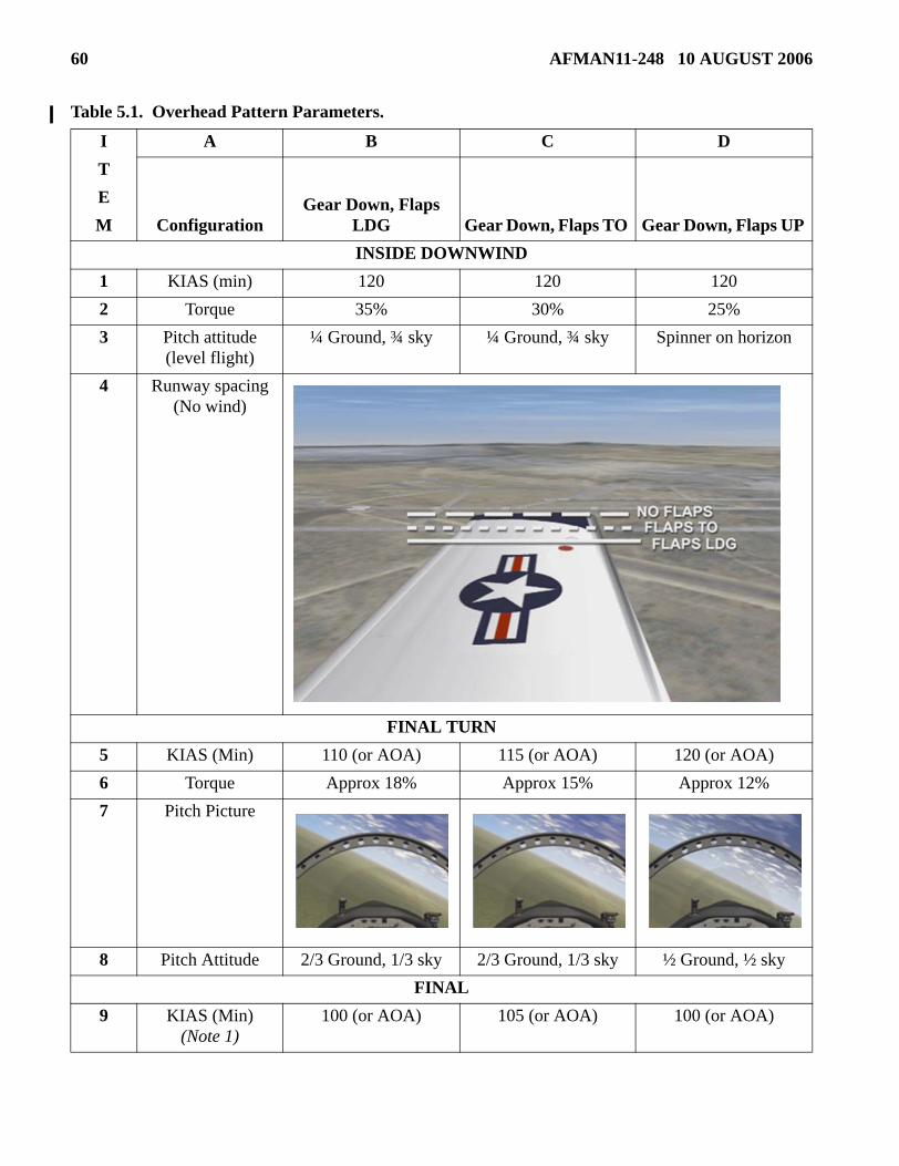
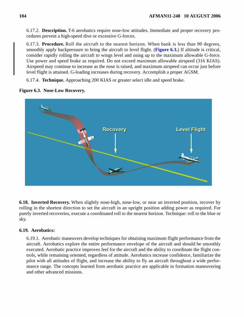
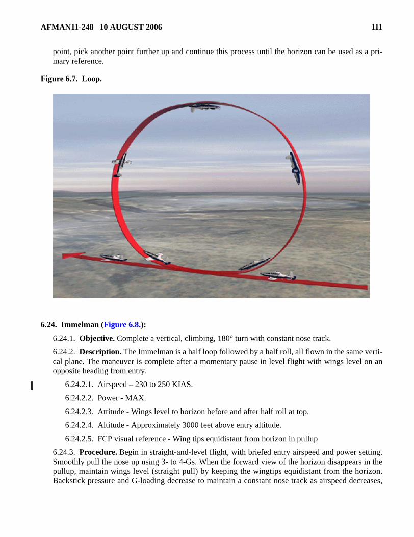
This change incorporates Interim Change 2007-1. It allows more flexibility when checking the brakes fortaxi (paragraph 3.9.1.); clarifies procedures for final turn go-around (paragraph 5.17.3.2.1.); defines whento stop a practice slip (paragraph 5.37.3.); establishes 2,500 feet above ground level (AGL) minimum alti-tude for high key (Figure 5.7.); clarifies emergency landing pattern (ELP) airspeed requirements (para-graph 5.39.2.1.); establishes 120 knots indicated airspeed (KIAS) as a minimum airspeed at low key(paragraph 5.39.4.5.1.); adds new procedures for flying ELPs through the weather (paragraph 5.41.); addsnew procedures for accomplishing configured slips (paragraph 5.42.); directs trim in the green for inten-tional spin entry (paragraph 6.13.2.1.); clarifies spin entry airspeed (paragraph 6.13.3.2.); clarifies noselow recovery procedure (paragraph 6.17.3.); modifies position description for low key checkpoints forELPs (Table 5.2.); and changes aerobatic parameters (Table 6.1. and associated paragraphs). A bar ( | ) inthe left margin indicates revision from the previous edition.
Chapter 1— GENERAL INFORMATION 15
1.1. Introduction To This Manual: .................................................................................... 15
1.2. How to Use This Manual. .......................................................................................... 15
6.14. Intentional Spin Entry (emphasizing near steady state spin recognition and recovery): ............................................................................................................ 101
AFMAN11-248 10 AUGUST 2006 7
6.15. Contact Recoveries from Abnormal Flight. ............................................................... 102
Figure 11.12. Route Fingertip Lead Change for a Three-Ship Formation. ..................................... 241
11.17. Forms Adopted. ......................................................................................................... 242
Attachment 1— GLOSSARY OF REFERENCES AND SUPPORTING INFORMATION 243
AFMAN11-248 10 AUGUST 2006 15
Chapter 1
GENERAL INFORMATION
1.1. Introduction To This Manual:
1.1.1. This manual provides the basic techniques and procedures necessary to safely and effectivelyemploy the T-6. It provides the basis for development of the necessary physical skills and mental apti-tude required to fly the T-6. The skills developed in the T-6 are applicable to flying any military air-craft and provide the foundation for all follow-on flying training.
1.1.2. TO 1T-6A-1 contains detailed instructions for inspections, checks, and procedures. It also pro-vides detailed information on aircraft systems and systems operation. The TO and this publicationcomplement each other.
1.2. How to Use This Manual. In general, this manual is organized in an order that parallels the trainingflow in pilot training. The first five chapters cover topics applicable to every sortie and the second fivechapters cover topics by category of flight. While each chapter builds on skills and concepts introduced inprevious chapters, the initial phase of training centers on near-simultaneous mastery of all concepts andskills introduced in Chapter 1-Chapter 6. During subsequent stages of training, study centers on specificcategory chapters. Regular review of previous material is required.
1.3. Introduction. The concepts in Chapter 1 apply to every kind of sortie flown in the T-6 and manyare universally applicable to flight in every type of military aircraft. The topics presented cover overarch-ing principles related to flying in general and flight training in the T-6 specifically. Full understanding ofthese general concepts is developed through study and flying experience, therefore, regular review of thischapter is required.
1.4. Safety. Safety is a critical component of successful mission accomplishment on every sortie. Thesafety mindset of each crew member is a key part in the overall safety of any flying operation. Each indi-vidual is responsible for minimizing risk to the people and assets under their control and identifyingpotential safety hazards.
1.4.1. Ground Safety. The flight line is an extremely busy environment. Moving aircraft, supportequipment and emergency vehicles create a hazardous environment. Extra diligence is required to pre-vent a tragic event.
1.4.1.1. Stay clear of the aircraft danger areas as depicted in TO 1T-6A-1, Section 2 (prop areasand/or the jet exhaust of running aircraft).
1.4.1.2. Secure loose items prior to entering the flight line to prevent foreign object damage(FOD).
1.4.1.3. Maintain constant watch for moving vehicles.
1.4.2. Flying Safety. Once airborne, safety assumes a more dynamic character. For example, a con-verging aircraft may unexpectedly appear or a malfunction can cause distractions during a criticalphase of flight. Safe operation requires an aggressive disposition towards gaining and maintaining sit-uational awareness. According to AFI 11-290, Cockpit/Crew Resource Management Training Pro-gram, situational awareness is an “aircrew member’s continuous perception of self and aircraft in
16 AFMAN11-248 10 AUGUST 2006
relation to the dynamic environment of flight, threats, and mission, and the ability to forecast, thenexecute, tasks based upon that perception.” Methods to maintain situational awareness include:
1.4.2.1. Clearing the airspace.
1.4.2.2. Monitoring aircraft systems.
1.4.2.3. Establishing and maintaining an emergency recovery plan before an emergency occurs.
1.5. Flight Discipline. Flight discipline is at the core of every flying operation. Maintaining the higheststandards of integrity, professional military pilots must adhere to the spirit and intent of governing guide-lines while executing the mission in the presence of temptation to do otherwise.
1.5.1. Flight discipline begins with mission preparation. Know the rules and procedures, study theprofile, ensure crew rest requirements are met, and show up prepared to fly. One unprepared crew-member can jeopardize the mission.
1.5.2. Flight discipline continues with the briefing. Be on time, be ready to discuss the mission, and/or be ready to brief. Ensure all questions are answered and mission requirements are understood.
1.5.3. Flight discipline is demonstrated in the air by executing the mission as briefed in accordancewith governing guidelines, from engine start to engine shutdown.
1.5.4. Flight discipline should be evaluated and specifically addressed during every mission debrief.
1.6. Checklist Discipline. TO 1T-6A-1CL, The Pilot’s Abbreviated Flight Crew Checklist, is a condensedversion of TO 1T-6A-1. The omission of a checklist item could lead to a dangerous situation. Therefore,positively confirm completion of all checklists regardless of how they are accomplished (for example,memory aid, mnemonic, approved unit-developed checklist or flight crew checklist). One technique toensure accomplishment of every step is to execute a few items from memory then reference the checklistpage to verify completion. Another technique is to complete the entire checklist and then refer back to thechecklist to verify completion. Further guidance on checklist use follows:
1.6.1. Unit-developed checklists (UDC) may be published to further condense many of the checklistsused during ground and flight operations. UDCs often include multiple checklists on a single sheetthat can be conveniently referenced without having to manipulate the flight crew checklist. UDCs arecommonly color coded for easy identification of steps that need to be highlighted for easy reference.
1.6.2. It is not necessary to refer to the checklist during critical phases of flight.
1.6.3. There will be only one pilot actively controlling the aircraft at any point in time. This pilot isreferred to in the rest of this manual as the pilot flying (PF). The PF is responsible for completion ofall checklists.
1.6.4. Checklist items marked “(BOTH)” must be completed in both the front and rear cockpit. ThePF will initiate a “(BOTH)” checklist item by challenging the pilot not flying (PNF). A “(BOTH)”item is not complete until a proper response is received from the PNF. The use of this method ofaccomplishment is why “(BOTH)” items are often referred to as “challenge and response” items.
1.6.5. Once started, attempt to complete checklists without interruption. If interrupted, or if it is dis-covered that an item was omitted, good techniques to get back on track include restarting at the firststep of the checklist or restarting two to three steps prior to the missed or interrupted checklist step. Donot start a new checklist until completing the previous one.
AFMAN11-248 10 AUGUST 2006 17
1.6.6. Throughout your flying career many checklists and required items are memorized throughmnemonics or standardized phrases. The purposes of these are to help you remember what needs to bedone at a specific time. One caution is that you do not give lip service to performing a checklist whenusing a standardized phrase or mnemonic. You must perform the checklist item or required check.
1.7. Single-Engine Mentality. The T-6 engine has an excellent record of reliability, but the potential forengine loss deserves special consideration. Two options exist for engine failure: ejection or recovery to asuitable airfield. Emergency landing pattern (ELP) practice increases the chance of successful recovery;however, the aircraft is fitted with a highly capable and proven ejection seat that should be used if there isany doubt about safe recovery. Special single-engine considerations include:
1.7.1. Extra vigilance for and a more conservative response to unusual engine indications. Withunusual engine indications, recover to a suitable airfield.
1.7.2. Maintain awareness of nearest suitable emergency airfields during all phases of flight.
1.7.3. Include field elevation in the calculation of available glide distance.
1.7.4. Consider intervening terrain along the route of flight to emergency airfields.
1.7.5. Do not shut down the engine in flight if it is producing useable torque unless it is confirmed onfire, vibrating excessively with indications of impending failure, or not required for recovery to theselected emergency airfield.
1.7.6. Set a minimum ejection altitude when immediate ejection isn’t warranted. This altitude is basedon energy level (altitude/airspeed), configuration, and position relative to a suitable emergency air-field. When on profile consider using O-R-M-3-2-1.
1.7.7. Determine if engine restarts should be attempted. Consider the time delay and altitude lostbetween restart initiation and usable torque, the risk of fire, the presence of FOD and whether or notthe engine is seized. (Often referred to as fire, FOD, or frozen.)
1.7.8. Consider winds and weather on the recovery route and at the emergency airfield.
1.7.9. Select update points to assess the progress of the ELP glide profile. Eject if it becomes apparentthat recovery to an emergency airfield is not possible.
1.8. Cockpit/Crew Resource Management (CRM):
1.8.1. The following topics are covered in detail in AFI 11-290; however, a simplified explanation ofthe concepts is sufficient for the early stages of flying training. The CRM program is designed todevelop aircrew skills in recognizing and responding to the conditions that lead to aircrew error.While flying, CRM is the effective use of all available resources to safely and efficiently accomplishmission objectives. CRM centers on the following six skills:
1.8.1.1. Situational Awareness. Continuous perception of self and aircraft in relation to thedynamic environment of flight, threats, and mission, and the ability to forecast, then execute tasksbased upon that perception.
1.8.1.2. Flight Integrity/Wingman Consideration. Utilization of all members of a flight toaccomplish the mission. Wingman consideration requires flight members to recognize eachother’s limitations and plan or act accordingly.
18 AFMAN11-248 10 AUGUST 2006
1.8.1.3. Task Management. Ability to establish priorities and alter a course of action based onnew information. Includes management of automation, effective use of available resources, check-list discipline, and compliance with standard operating procedures.
1.8.1.4. Communications. Sharing of information with others to cause action. Communicationsmay direct, inform, question, or persuade.
1.8.1.5. Risk Management or Decision Making. Logic-based, common sense approach to deci-sion making based on human, material, and environmental factors. The goal is to match risk to themission, not completely eliminate risk.
1.8.1.6. Mission Planning, Briefing, and Debriefing. Includes premission analysis and plan-ning, briefing, and post mission debrief.
1.8.2. CRM is designed to focus aircrew members on agencies, procedures, and resources available toenable mission success. To do this, locally developed CRM checklists describe behaviors to reinforceand others to avoid. A CRM topic will be included in the mission brief, should be tailored to specificmission requirements or conditions, and will be evaluated during the debrief.
1.9. Operational Risk Management (ORM). Flying is inherently risky. ORM is the process used toidentify and reduce the risks of flying to an acceptable level. Locally developed ORM processes balancetraining benefit and risk. Risk can often be minimized by mission changes that do not negatively impacttraining. Typical ORM assessments include analysis in the following general categories:
1.9.1. Environmental conditions (for example, weather, bird status, index of thermal stress).
1.9.2. Mission profile (for example, formation, VFR, low level, use of uncontrolled airfields).
1.9.3. Pilot factors (for example, experience level, fatigue, currency).
1.10. Mission Preparation. Mission success is directly related to mission preparation. Flying time islimited and solid preparation maximizes the effectiveness of limited airborne time. There are four areas ofmission preparation:
1.10.1. General Study. Study in general areas builds a foundation of knowledge for pilot training,other formal training courses, and operational missions. Some topics such as the flight manual are air-craft specific and other topics such as local area procedures are location specific. Areas of studyincluding instrument rules and procedures (AFMAN 11-217, Instrument Flight Procedures, and AFI11-202, Volume 3, General Flight Rules), weather, aerodynamics, FLIP, and navigation, are genericbecause they apply to any aircraft, at any location, flying any type of mission. General study is a con-tinuous process that is an integral part of a successful career in military aviation.
1.10.2. Mission Selection. Preparation cannot be focused until there is a specific mission. In formaltraining courses, missions are normally determined by a syllabus. However, in many cases, syllabiprovide a basic framework and missions are tailored to individual training needs and requirements byreviewing the student grade book or training folder. In the formal training environment of pilot train-ing, mission selection consists of objective setting and then profile selection. Objectives focus trainingto specific areas that must be accomplished to make the mission successful. The profile is the exactlist of maneuvers performed on a particular sortie. Consider the following when setting objectives:
1.10.2.1. The overall mission objective should give the big picture. What must occur for the sortieto be successful? These objectives are usually pulled from the syllabus in a formal training course.
AFMAN11-248 10 AUGUST 2006 19
1.10.2.2. Training objectives are specific and help determine success in relation to the syllabus,course training standards, continuation training requirements, etc. A valid objective is realistic,achievable, and measurable, and it has three stated or implied parts:
1.10.2.2.1. Performance. Describes action and is specific; for example: no-flap landing,loop, and formation takeoff.
1.10.2.2.2. Conditions. Starting parameters; for example, begin the loop with MAX powerand 250 knots.
1.10.2.2.3. Standards. Required parameters to meet during the maneuver. Base these on theflight manual, this manual, course training standards, current directives, or the level of profi-ciency demonstrated previously by the pilot performing the maneuver or task.
1.10.3. Mission Specific Study. Study in areas specifically related to the mission. This includes gen-eral study areas that are specifically related to the mission (for example, study of AFMAN 11-217,Volume 1, Instrument Flight Procedures, before an instrument training sortie). Mission specific areasinclude, but are not limited to: operational restrictions (for type of sortie), approach plate (IAP)review, local area procedures (for that sortie), maneuver review, and daily study topics (for example,emergency procedure [EP] of the day). Specific study also includes chair flying. Chair flying is a men-tal review of the sortie. It is visualization of specific maneuvers and techniques, and mental review ofchecklists and specific tasks. Review individual maneuvers, in appropriate sections of the flight man-ual and this manual, before each sortie. Study should focus on the primary mission, but some timemust be devoted to possible alternate missions.
1.10.4. Mission Planning. The previous facets of mission preparation generally prepare the pilot forthe mission, but there are tasks that must be accomplished to execute the specific mission on a specificday. Mission planning includes all the tasks that turn the plan into reality. The following list includesmany of the mission planning steps:
1.10.4.1. Check notices to Airman (NOTAMs), weather, and operations notes.
1.10.4.2. Sign off Go/No-Go (items that must be accomplished before flying).
1.10.4.2.1. Flight crew information file (FCIF).
1.10.4.2.2. Squadron or pilot read files.
1.10.4.3. Attend mass brief (some formal programs brief the entire class before individual mis-sion briefings occur).
1.10.4.4. Check aircraft sign out data, local profile, call sign, etc.
1.10.4.5. Schedule or reserve airspace (limited special use airspace, low level MTR, etc.).
1.10.4.6. Check bird hazard models.
1.10.4.7. Call destination if flying to an airfield other than the home airfield.
1.10.4.8. Review local restrictions (ramp freeze, construction, etc.).
1.10.4.9. Prepare briefing (briefing board, EP of the day, etc.).
1.10.4.10. Compute takeoff and landing data (TOLD).
1.10.4.11. Compute or check weight and balance.
20 AFMAN11-248 10 AUGUST 2006
1.10.4.12. Plan fuel, select route, file a flight plan.
1.11. Fuel Considerations. Unlike many operational and training aircraft, the T-6 is not fuel limited onmost training sorties. Generally, syllabus directives, not available fuel, determine the duration of most sor-ties; however, regular fuel checks are still required and are an important part of each mission.
1.11.1. Bingo, joker, and normal recovery fuels are defined in AFI 11-2T-6, Volume 3, T-6 OperationsProcedures.
1.11.2. AFI 11-202, Volume 3 defines fuel requirements for all sorties.
1.11.3. Bingo fuel and at least one joker fuel is briefed on every mission. Joker fuel is set at pre-planned transition points in the sortie. A mission may require several joker fuels.
1.11.4. If bingo fuel is reached, recovery should be initiated to arrive at the intended destination withthe required fuel. On most T-6 syllabus training sorties, recovery is normally initiated prior to reach-ing bingo fuel due to sortie duration limitations.
1.11.5. Mission priorities and flight conditions may change while airborne (for example, area assign-ment, weather conditions, alternate airfield requirements etc.). The aircraft commander (AC) of a sin-gle ship mission or the flight lead (FL) of a formation may adjust joker and/or bingo fuels during flightto accommodate mission conditions.
1.12. Mission Briefing. The AC or FL may or may not be the actual briefer, but in every case will ensurethat each mission is thoroughly briefed and debriefed.
1.12.1. Briefings set the tone for all missions. All crewmembers will be on time, prepared, and in pos-session of all required material and information. Complete all preflight administrative tasks (such aschecking the weather and the NOTAMS) before the briefing.
1.12.2. As a minimum, locally established briefing guides will cover all required items. Discuss for-mal special interest items (SII) during all briefings.
1.12.3. Other crewmembers or formation members will be prepared to assist the AC or FL.
1.12.4. The briefing should focus on how to successfully accomplish the established objectives.
1.13. Debrief. The purpose of debrief is to determine if mission objectives were achieved. From bothadministrative and tactical perspectives, the AC and/or FL should:
1.13.1. Cover what went right or wrong, root causes of errors, and how to improve subsequent mis-sions.
1.13.2. Address all questions, concerns, and address disagreements.
1.13.3. Debrief by objective, examining how well each objective was achieved.
1.13.4. Summarize the mission with emphasis on major learning points and considerations forimprovement of deficient areas on future missions.
1.14. Tandem Seat Challenges. Limited visibility of the crewmember in the other cockpit makes it dif-ficult to judge intentions, anticipate actions, and verify aircraft systems configuration. Verbal communica-tion must compensate for the lack of inter-cockpit visibility. Most functions are controllable from either
AFMAN11-248 10 AUGUST 2006 21
cockpit, however some items can only be manipulated or directly checked in the front cockpit. To reducethe potential adverse impact of tandem seating:
1.14.1. Know which systems are controlled from the front cockpit (FCP) or rear cockpit (RCP) andcan only be monitored or controlled from the opposite cockpit through verbal or visual coordination:
1.14.1.1. Activation of the auxiliary battery- FCP.
1.14.1.2. Manual fuel balance L/R switch - FCP.
1.14.1.3. Environmental control system (ECS) controls - FCP.
1.14.1.4. Parking brake position - FCP.
1.14.1.5. Emergency gear extension - FCP.
1.14.1.6. Interseat sequencing system (ISS) - RCP.
1.14.1.7. Altimeter settings are independently set in each cockpit - FCP and RCP.
1.14.2. Know which systems, although controlled from the FCP can be checked from the RCP andhow:
1.14.2.1. Check bleed air inflow by pressing the G-suit test button.
1.14.2.2. Confirm OBOGS operations are on by turning off the supply lever.
1.14.2.3. Confirm defog operation by sound or temperature of the piccolo tubes.
1.14.2.4. Confirm external light operation (on the ground) by looking for reflections from adja-cent aircraft or other surfaces.
1.14.3. Consider FCP pilot landing if RCP visibility is severely compromised.
1.14.4. Ensure all crewmembers thoroughly understand transfer of aircraft and/or systems control.
1.15. Transfer of Aircraft and Systems Control. Only one pilot, at a time, can fly the aircraft. It is vitalfor flight safety to clearly establish who is the PF and who is the PNF as fatal accidents have occurredwhen two pilots attempted to fly the aircraft simultaneously. The PF is responsible for checklist comple-tion and systems operation, however, the PF may task the PNF to operate systems. Due to the importanceof proper transfer of aircraft control, the following rules apply:
1.15.1. Transfer of aircraft control:
1.15.1.1. The PF relinquishing control says, “You have the aircraft.”
1.15.1.2. The PNF assumes control and says, “I have the aircraft,” and noticeably shakes the con-trol stick.
1.15.1.3. The order may be reversed as the AC always retains the authority to take aircraft controlwhen required. The order of transfer is less important than each crewmember executing his/herrole in accordance with the procedures listed.
1.15.1.4. If the AC, as the PNF, says “I have the aircraft” and noticeably shakes the control stick,the PF must immediately relinquish control of the aircraft, and say “You have the aircraft.” This isan example of how the order is reversed but the roles continue to be executed.
22 AFMAN11-248 10 AUGUST 2006
1.15.1.5. Using the exact words is critical to establish proper habit patterns that enhance swift,unambiguous transfer of aircraft control. Do not use of other words such as “it” or “jet” in lieu ofthe term “aircraft” as they can be misunderstood, misheard, and create confusion.
1.15.2. In the event of intercom failure, the PF signals the desire to relinquish aircraft control bysmoothly pushing the rudder peddles in a back and forth motion and the PNF assumes control by vig-orously shaking the control stick. As a technique, the pilot relinquishing control raises both hands inthe air for the other pilot to see either directly from the RCP or using mirrors from the FCP.
1.15.3. Never relinquish control of the aircraft until the other pilot has positively assumed control ofthe aircraft (shaken the control stick).
1.15.4. Do not hesitate to relinquish control when directed by the IP.
1.15.5. Immediately query the other crewmember in case of confusion.
1.15.6. The tandem seating and “last use, last in control” setup of T-6 systems can be confusing if notmanaged properly. It is crucial to coordinate systems use to avoid inadvertent inputs. Systems thatrequire crew coordination include: canopy, radio management unit (RMU), global positioning system(GPS) and electronic flight instrument system (EFIS) configuration. The PF controls all of the sys-tems of the aircraft unless a transfer of that system has been clearly communicated between the crew-members. The PNF should also communicate when transfer of the system back to the PF.
1.16. Clearing. Each crewmember is responsible for collision avoidance regardless of rank, experience,or cockpit position, whether IFR or VFR. The three primary tools for clearing in the T-6 are eyes, radios,and the Naval Aircraft Collision Warning System (NACWS) or Traffic Advisory System (TAS). In addi-tion, air traffic control (ATC) shares aircraft separation responsibility with the pilot, and provides separa-tion between instrument flight rules (IFR) and participating visual flight rules (VFR) aircraft operating incontrolled airspace. The use of radar monitoring, assigned areas, or ATC separation can assist in but doesnot relieve pilots of the responsibility to clear. The following principles apply to clearing regardless offlight conditions:
1.16.1. Visual detection is the most important factor in clearing for other aircraft. The followingmethods can help see other aircraft:
1.16.1.1. Visual Scanning. Search an area with an arc of approximately 20-30° at a time andfocus on a distant point (cloud, ground reference, etc.) within the arc for 3-5 seconds. After cross-checking instruments in the cockpit, it is necessary to refocus on a distant point because the eyewill naturally focus at a distance of about 18 inches.
1.16.1.2. Heading Changes. When on a collision course, another aircraft appears stationary inthe canopy and is difficult to see. The eye most readily detects line of sight motion. Slight headingchanges can create the relative movement required for detection of the other aircraft. This methodis most effective when ATC or NACWS provides traffic alerts for aircraft that are not acquiredvisually.
1.16.1.3. Wing Flashes. When an aircraft is known to be close but not visually acquired, a wingflash or rock can create the necessary movement for detection.
1.16.1.4. Radios and NACWS or TAS. Position reports and NACWS or TAS range or positioninformation can help narrow visual clearing efforts to specific quadrants. Prioritize but do notchannelize as the accuracy of the information provided can vary depending on specific conditions
AFMAN11-248 10 AUGUST 2006 23
and capabilities. Knowledge of local area traffic can also cue crewmembers to the most likelyareas of potential conflict.
1.16.2. If the PNF sees a hazard, point it out to the PF, indicate left or right, a clock position, and rela-tionship to the horizon (high, level, or low). For example, traffic, right 2 o’clock low, tracking right toleft. See Figure 1.1. through Figure 1.3. for canopy code references.
Figure 1.1. Clock Positions.
24 AFMAN11-248 10 AUGUST 2006
Figure 1.2. FCP Canopy Code, Elevation.
AFMAN11-248 10 AUGUST 2006 25
Figure 1.3. FCP Canopy Code, Azimuth.
1.16.3. If time is critical and collision is imminent, the PNF should take control of the aircraft andavoid the hazard. Ensure the intended flight path is well clear of other aircraft (500 feet minimum).
1.16.4. Be aware of the restrictions to visibility created by the canopy bows.
26 AFMAN11-248 10 AUGUST 2006
1.16.5. Use clearing turns when warranted to clear blind spots beneath the aircraft fuselage andwings, especially in training areas. Clearing turns can consist of turns that include high bank angles orturns of approximately 90° off the established heading.
1.16.6. Local traffic patterns present the greatest collision potential. To reduce risk, military and civil-ian traffic patterns utilize standard procedures. While visual scans are vital in this environment, pat-tern procedures, including proper radio calls, are the primary means of deconfliction. The followingcan improve clearing in the pattern:
1.16.6.1. Knowledge of choke points in the pattern. Military: 90-to-initial, VFR entry, closeddownwind, high-to-low key, and the perch point. Civilian: pattern entry, downwind, and final.
1.16.6.2. Proper setting of the NACWS or TAS. Selection of a smaller range improves usability ofNACWS or TAS information in the pattern.
1.16.6.3. Compliance with mandatory radio transmissions. They serve as position reports essen-tial to pattern deconfliction. Likewise, other aircraft’s radio transmissions help visually acquireaircraft in the pattern (commonly referred to as “clearing on the radios”).
1.17. G-Awareness. The T-6 is flown in a variety of flight regimes that result in rapidly changingG-forces. To avoid gray out, blackout, or G-induced loss of consciousness (GLOC) an effective anti-Gstraining maneuver is essential. Physical fitness, adequate rest, and proper hydration can improve G-toler-ance.
1.17.1. Anti-G Straining Maneuver (AGSM). Accomplish the AGSM by firmly contracting mus-cles of the legs, abdomen, and chest. As the amount of G increases, increase the intensity of the strain,and attempt to exhale through a closed airway. Continue to strain and simultaneously breathe approx-imately every 2 to 3 seconds. Think of the AGSM as a continuum. As the amount of G increases,increase the intensity of the strain and pay careful attention to proper breathing technique. Do not holdthe strain too long (more than 3 seconds) without breathing as this reduces G tolerance. If gray outoccurs at the onset of G forces, application of the AGSM may not eliminate the gray out. If altitudeand/or airspeed are not critical, return to 1 G flight, reapply the anti-G strain, and then continuemaneuvering. Use caution not to exceed aircraft or personal G-limits.
1.17.2. AGSM Effectiveness. It is important to start the AGSM before the onset of G-forces andmaintain the strain throughout the period of increased G-loading. The amount of strain required varieswith the amount of applied G-force. An effective AGSM uses full muscle contraction and keeps con-stant breathing cycles. Lower-G situations still require all elements of a full AGSM, but at a lowerlevel of strain intensity.
1.17.3. AGSM Demonstration. The AGSM demonstration allows practice of the anti-G strain tech-nique and familiarization with increased G-loading in a controlled setting. The demonstration consistsof a series of turns, each at a constant G-level, with a break between turns for critique and rest. Themaneuver is flown at gradually increasing G-levels, starting at 2 Gs and increasing to 4 Gs, dependingon proficiency. If, at any time, personal G-tolerance limits are approached, inform the other crew-member. The demonstration should be of sufficient duration to ensure a proper AGSM. The AGSMcycle should last from 10 to 15 seconds with at least 4 to 5 breathing cycles.
1.17.4. G-Awareness Exercise. Accomplish a G-awareness exercise on sorties that include maneu-vers that require or may result in 3 or more Gs.
AFMAN11-248 10 AUGUST 2006 27
1.17.4.1. The G-awareness exercise should be a level or slightly descending turn, using maximumpower. Begin the maneuver with sufficient airspeed to sustain 4 Gs. (For planning purposes, useapproximately 200-220 knots minimum for a level to slightly descending turn where the noseremains within 10° of the horizon.) The G-onset rate should be slow and smooth, allowing suffi-cient time to evaluate the effectiveness of the AGSM and determine G-tolerance. Increase Gs toapproximately 4 Gs and maintain for approximately 4 to 5 breathing cycles in order to allow fullcardiovascular response.
1.17.4.2. For advanced aerobatic and formation training, the G-awareness exercise should beflown to G-loads of 4 to 5 Gs.
1.17.4.3. If gray out begins during the demonstration, return to 1 G flight, reevaluate the strain,and then smoothly reenter the G-awareness exercise.
1.17.4.4. If personal G-tolerance is lower than required for the sortie, terminate high-G maneuver-ing.
1.18. Radio Procedures. The PF is responsible for all radio calls. The PNF may transmit without trans-fer of aircraft control; however, the PF must be notified (see paragraph 1.15.6.). EXCEPTION: instruc-tors may immediately correct improper radio calls without first notifying the student. Radio procedures,definitions, and guidance are contained in the following publications: AFI 11-204, AFMAN 11-217 Vol-ume 1, FAA Aeronautical Information Manual (AIM), FLIP/Flight Information Handbook, and individualwing and/or squadron instructions. Although these publications do not cover all situations, pilots shouldattempt to use standard phraseology as much as practical. Standard terminology minimizes radio conges-tion and facilitates effective communication.
1.18.1. Clarity. The single most important factor in pilot-controller communications is comprehen-sion. Voicing what is required correctly through standard phraseology is paramount. Use of nonstand-ard and improvised phrasing, while common, only contributes to miscommunication and should beminimized. Nonstandard phraseology contributes to misunderstood clearances and aircraft mishaps.When uncertain of the meaning of standard phrases used by controlling agencies, clarify with plainlanguage.
1.18.2. Brevity. Brevity is second only to clarity. Every second you are talking on the radio is a sec-ond that is unavailable to the controllers or other pilots. Provide controllers with the informationneeded, nothing more, nothing less, in the format expected. Likewise, do not omit needed informationthat may require the controller to query you for the missing information as this also wastes airtime.
1.18.2.1. Do not depress the microphone button during other transmissions. Anticipate otherparty’s replies to ATC and/or pilot transmissions and do not interrupt. Try to avoid transmittingwhen another aircraft is in a critical phase of flight (for example, in the flare).
1.18.2.2. Whenever possible, format radio calls as follows: agency calling, call sign, location, andrequest. For example, “SAN ANTONIO APPROACH, FAZER 87, AREA 8 LOW, REQUESTAUGER ILS, WITH BRAVO.”
1.18.2.3. Adding verbiage that is not required clutters the radio frequency. Avoid meaninglessphrases such as “with you,” “checking in,” “with a flash,” “at this time,” “be advised,” particularlyon congested frequencies. Provide the controllers with the information needed simply and clearlyin the format expected. Nonstandard radio calls take more time to understand.
28 AFMAN11-248 10 AUGUST 2006
1.18.2.4. Include all required information in calls to ATC to prevent the requirement for additionalATC queries. When making a detailed request, however, avoid confusion and frequency conges-tion by first getting the controller’s attention (for example, “DEL RIO APPROACH, TEXAN 10,REQUEST”). After the controller acknowledges, state the request.
1.19. GPS Usage. Updated equipment such as GPS makes it even more important to understand and con-tinue to focus on the building block approach to navigation and area orientation in primary training. VORand DME navigation skills will continue to be emphasized throughout all phases of training. To enhancefollow on training, GPS usage is introduced early in training. Using the GPS can offer a simple solution toarea orientation and navigation in the early stages of training allowing the focus to be on learning to fly anAir Force aircraft.
1.20. Emergency Procedures. Three basic rules apply to all emergency procedures: 1) maintain aircraftcontrol, 2) analyze the situation and take proper action, and 3) land as soon as conditions permit. If the air-craft cannot be recovered safely, ejection may be the only option.
1.20.1. Maintain Aircraft Control. Fly the aircraft. Flying is the most important task during anyemergency. The PF flies the aircraft until the AC directs otherwise. Maintain an aircraft attitude thatallows for an appropriate response to the emergency situation. Set power and trim to help maintaincontrol. Aircraft control may include the initial turn and/or climb to a recovery airfield. One techniqueto help prioritize pilot action, that is applicable in normal and emergency situations, is the memoryaid, “Aviate - Navigate - Communicate.” Fly the aircraft first!
1.20.2. Analyze the Situation and Take Proper Action. Indications of a problem include: aircraftperformance, engine instrument readings, or the cockpit warning system (CWS). If dual, confirm sus-pect indications with the other crewmember. If the master warning/master caution light is illuminated,look at the panel before resetting the system by pushing the light to turn it off. Consider all indicationswhen diagnosing the problem. Proper actions are dependent on the correct analysis and careful con-sideration of the circumstances. In many cases, the proper actions are clear, however, alternate coursesof action may exist depending on the nature of the emergency, flight conditions, and pilot proficiency.Pilot actions may include:
1.20.2.1. Critical Actions. Boldface procedures are committed to memory and must be per-formed immediately to prevent aggravation of the emergency. Sufficient time may not exist to ref-erence the checklist. After critical steps are performed, the checklist is referenced for noncriticalcleanup steps. Additional, noncritical checklists may be required for successful recovery.
1.20.2.2. Noncritical Actions. These checklist steps contribute to an orderly sequence of eventsand improve the chances for successful recovery. Warnings, cautions, and notes in the checklistmust also be reviewed during checklist execution.
1.20.2.3. Communication with the Supervisor of Flying (SOF), Top-3 or Operations Super-visor, or Runway Supervisory Unit (RSU) Crew. These experts can read checklists, referencethe flight manual, contact the aircraft manufacturer, check calculations, identify potential chaseships (airborne aircraft than can rejoin on a distressed aircraft to help with analysis and recovery),or offer advice on course of action and recovery plans.
AFMAN11-248 10 AUGUST 2006 29
1.20.2.4. Communication with ATC. ATC can help identify suitable recovery airfields, findrequired frequencies, aid navigation with vectors, alert emergency response assets, identify haz-ardous weather, or help find a chase ship.
1.20.2.5. Evaluation of Possible Recovery Airfields. The initial airfield selected may notalways be the best. Changes to energy state (if torque deficient) may eliminate or expand airfieldoptions. Additional research, once initial actions are complete, may identify a better option (basedon weather, runway available, emergency response available, etc.).
1.20.2.6. Request for Chase Ship. Chase ships can be a tremendous asset during emergency sit-uations. They can lead aircraft with instrument malfunctions through weather, provide assistancesimilar to ground-based experts, clear for task saturated emergency aircraft, or handle communi-cations with ATC.
1.20.2.7. Review of Approach/Landing and Post-Landing Actions with Other Crewmemberor Ground-Based Agencies. Crew coordination is essential for successful recovery and incidentfree emergency termination. Clear communication with ground-based agencies is necessary tocoordinate contingencies such as possible runway closure.
1.20.3. Flight Manual Landing Recommendations:
1.20.3.1. Land as soon as possible. A landing should be accomplished at the nearest suitable land-ing area considering severity of emergency, weather conditions, field facilities, ambient lighting,and command guidance.
1.20.3.2. Land as soon as conditions permit (determined by nature of emergency and sound judg-ment).
1.20.3.3. Land as soon as practical. Emergency conditions are less urgent. The mission should beterminated; however, the degree of emergency is such that an immediate landing may not be nec-essary.
1.20.4. CRM in an Emergency. A successful conclusion to any emergency results from thoroughsystems knowledge, sound judgment, and effective CRM. Several resources are available to aid suc-cessful recovery.
1.20.4.1. Inside the Cockpit. The aircraft commander determines who flies the aircraft, based onpilot workload and the experience level and ability of both pilots. The PNF can read the checklist,monitor systems, provide advice, and maintain situational awareness on the nearest suitable land-ing field. The flight crew checklist, in-flight guide, flight information handbook, or other flightinformation publications (FLIP) can contain useful information.
1.20.4.2. Outside the Cockpit. Outside help can be essential whether dual or solo during anemergency. ATC agencies can alert emergency services and provide traffic priority. The SOF,Top-3 or operations supervisor, or RSU crew can provide assistance with checklists, recommendcourses of action, and monitor the situation. A chase ship can provide inspection of aircraft areaswhich can not be seen from either cockpit.
1.21. Tabletop and Standup Emergency Procedures (EPs):
1.21.1. The purpose of tabletop EPs is to expose student pilots to as many different emergency situa-tions as possible on the ground, before they are faced with actually handling one while airborne.
30 AFMAN11-248 10 AUGUST 2006
Standup EPs provide the same exposure; however, they have the added pressure of performing whilepeople are watching over your decisions. This added pressure simulates the stress of an actual air-borne emergency.
1.21.2. The objective of tabletop and standup EPs is to exercise your knowledge and availableresources to formulate and execute a plan to get you safely on the ground. All the same principles out-lined in paragraph 1.19. apply to these practice situations.
1.21.3. Though there can be many techniques used to solve most problems, the use of the mnemonicA-A-B-C-D-E-F (Figure 1.4.) will help put the basic EP principles into logical steps.
1.21.3.1. A—Aircraft Control. Maintaining aircraft control dictates that you continue to fly theaircraft and get to a stable flight condition that allows you time to analyze the situation. In the con-tact phase, this may involve a contact recovery or OCF recovery. In low-level navigation, it mayinvolve starting a climb to the top of the route. In formation, it may involve calling knock it off(KIO) and taking the number 1 position. During this step, describe how you will use the controlstick, rudder, and PCL to achieve a stabilized flight condition.
1.21.3.2. A—Analyze the Situation:
1.21.3.2.1. During this phase of the practice situation, time stands still (TSS) because youreyes and brain work a lot faster in the aircraft than you can talk when asking questions aboutthe status of different systems on the aircraft. At this point in time, ask your IP questions aboutthe aircraft.
1.21.3.2.2. Acronyms can help you analyze the situation. A common one is a FEVER checkfor engine problems. F stands for fluctuating fuel flow. A properly working engine, at a con-stant PCL setting should not have fuel flow jumping around more than 10 pounds per hour. Estands for excessive ITT. The PMU, if still online, should limit the ITT in range, if not, youhave a problem. V stands for visual signals. Smoke, flames, and oil on the windscreen aresymptoms of engine problems. E stands for erratic engine operations and R stands for rough-ness. Pointers jumping and an engine making strange noises also indicate problems.
1.21.3.2.3. If at any time during analyze the situation step, you realize there may be an engineproblem, perform the first four steps of the precautionary emergency landing (PEL) checklist(turn, climb, clean, check [TCCC]). Once pointed toward the nearest suitable airfield, get theaircraft on an emergency landing pattern (ELP) profile, and continue to analyze the situationfor impending engine failure. Even if you misanalyzed the problem, you are at least in a saferposition than if you had ignored it.
1.21.3.2.4. Other things to analyze during this step include, but are not limited to: avionics,lights and tones, circuit breakers, and outside aircraft structure (possibly via a chase ship). Asthe analysis continues do not spend more time than necessary, just to stall for time. If you thinkyou know what is wrong with the aircraft, go with it. Remember, even though time stands stillin the flight room, it does not in the aircraft.
1.21.3.3. B—Boldface. Once you have analyzed the situation, time resumes, and it is time to takethe proper action and perform any boldface required. During this step, state the boldface steps thenverbally execute them (for example, Green ring – pull [as required]. I will perform this step bypulling the green ring on the ejection seat with my left hand.) Applying a boldface procedureshould require you to do something with the aircraft. (For example, the engine failure during flight
AFMAN11-248 10 AUGUST 2006 31
boldface will require you to trim the aircraft to 125 knots; the abort boldface will require you touse rudder to keep the aircraft near the centerline, etc.). Once the boldface is complete, ensure theaircraft is still under control and analyze your action. Did the boldface do what it was intended todo? (Perform another FEVER check.) Is the fire out? Do you feel pressure in you mask from theoxygen bottle? After you have analyzed ask yourself, is there another boldface that applies.Engine failure during flight may lead to immediate engine start. Continue in this loop until thereare no more boldface that apply.
1.21.3.4. C—Cleanup items and/or Checklists. During this step you will perform the cleanupitems (the non-boldface steps) of the boldface checklists and accomplish other non-boldfacechecklists that may apply. Once you apply a checklist, refer back to aircraft control. (For example,if you perform the non-boldface oil system malfunction checklist when the PCL was at MAX,moving the PCL below 60 percent will require the control stick, rudder, and PCL to be moved tocompensate for less thrust.) Continue to loop through the above steps until no more checklists arerequired. After all the flight manual EP checklists are performed, use the inflight guide to helpdetermine any other pertinent data required to recover the aircraft (for example, local NORDOprocedures).
1.21.3.5. D—Declare, With a Plan. Once you establish your game plan, let the appropriateauthorities know what is wrong and what you plan to do. When you talk to ATC, the SOF or RSUcrew, make sure you can tell them (easily memorized by the NTSB acronym): nature of the emer-gency, time to landing, souls on board, and briefing (your plan of action). Know what you aregoing to do in terms of pattern type (straight-in, ELP, overhead, instrument approach) and howyou are going to stop the aircraft (stop on the runway and emergency ground egress, stop on a taxi-way, or taxi back to parking). Be knowledgeable enough that you have most of the answers beforethe question is asked.
1.21.3.6. E—Egress/Ejection. Review Emergency Ground Egress and Controlled EjectionChecklists. Determine when you will eject if the situation deteriorates and leads to an ejection sce-nario.
1.21.3.7. F—Follow the Plan. This part of the tabletop or standup EP (take proper action andland as soon as conditions permit), is where you continue to chair fly the emergency to a safe land-ing. In real life, this is where you execute your plan to get safely back to the flight room. During atabletop or standup EP, talk your IP though all the steps, descent check, arrival and pattern proce-dures, and safely exit the airplane.
32 AFMAN11-248 10 AUGUST 2006
Figure 1.4. A-A-B-C-D-E-F Method of Accomplishing Practice EPs.
AFMAN11-248 10 AUGUST 2006 33
Chapter 2
BASIC T-6 FLIGHT PRINCIPLES
2.1. Introduction. This chapter discusses basic terms that apply to all aircraft. It explains concepts andterms associated with the T-6 as a single-engine, propeller-driven aircraft. Knowledge and understandingof these terms and their associated aerodynamic effects is essential to successfully fly the T-6.
2.2. Control Effects. Each flight control affects the attitude of the aircraft by controlling movementabout one of three axes (Figure 2.1.). Control movements result in the same predictable aircraftresponses, regardless of the attitude of the aircraft. The pilot is the approximate pivot point about whichall changes of attitude occur.
Figure 2.1. Control Axes.
2.3. Use of Controls. When a control surface is moved out of its streamlined position, air flowing past itexerts pressure against the control surface and tries to return it to neutral. These air forces on control sur-faces are felt on the control stick and rudder pedals. Control forces are directly proportional to airspeedand control deflection and provide feedback to the pilot. This feedback, which is felt in terms of forces felton the control stick and rudder pedals, identifies trim requirements. Air forces can impede positioning ofthe controls to the desired position.
2.3.1. How to Use the Rudder. When properly positioned, the heels of the feet rest upon the cockpitfloor and the balls of the feet touch the rudder pedals. Rudder application should be smooth, similar to
34 AFMAN11-248 10 AUGUST 2006
application of brakes in an automobile. In order to optimize control feel, maintain firm but relaxedpressure on the rudders.
2.3.2. How to Use the Control Stick. Although many maneuvers generate heavy control stickforces, a firm but light touch on the control stick optimizes control feel. Hands and arms shouldremain relaxed. Ideally, during cruise operations fingertips on the control stick is all that should beneeded. Fingertips give the best feedback on minute changes of aircraft trim.
2.3.3. How to Use the PCL:
2.3.3.1. Known power settings provide a useful starting point for PCL position. Starting withpower settings close to the desired setting minimizes torque and propeller effects. General powersettings are listed in Table 2.1. These pitch and power settings are approximate, and vary from air-craft to aircraft based on factors such as aircraft weight, pressure altitude, and temperature.
2.3.3.2. The PCL requires relatively little travel to change the power. A small movement of thePCL can result in a larger than desired power change. One technique for precise power control isto hold the left hand fixed against the fuselage wall and modulate the PCL with only the fingertips.Because torque is computer controlled, the torque may change slightly after the PCL is set.
2.3.3.3. Place the palm of the hand on the PCL. As a technique, to make small and controlledmovements, let your finger rub against the inside cockpit wall to aid in determining amount ofPCL movement. Use caution when placing wrist on the PCL with fingers extended near the PCLcutoff finger lift. There have been several instances of improper hand placement and inadvertentengine shut down.
Table 2.1. General T-6 Airspeeds and Power Settings.
NOTE: Add MSL altitude (for example, at 3,000 feet MSL, set 53 percent torque).
I A B C D E F G T E M Maneuver Airspeed Gear Flaps Pitch Power Other 1 Level flight 250 UP UP 2° NL 93% ±1% per 1,000
feet 2 200
1 degree NL 50% + altitude
(see note) 3 150 2° NH 32% 4 Takeoff 85 DOWN TO 7° NH MAX 5 Tech climb 180 UP UP 9° NH 6 160 12.5° NH 7 140 17° NH
AFMAN11-248 10 AUGUST 2006 35
2.3.4. Other Devices. Other devices controlled by the pilot that also affect aircraft handling are theflaps, landing gear, and speed brake. However, their effects, for the purposes of general aircraft han-dling, are incidental. Trim sufficiently compensates for minor aerodynamic effects of these systems.
2.4. Trim:
2.4.1. There are many factors in various conditions of flight that affect the forces felt in the controls.Trim is needed to compensate for these control stick forces to prevent fatigue and increase smooth-ness. When properly trimmed an aircraft can and should be flown with just the fingertips on the con-trol stick to allow slight out of trim conditions to be easily felt.
2.4.2. Trim tabs are small movable surfaces attached to the primary flight control surfaces (rudder andelevator) that act as levers to equalize pressure exerted on either side of the parent control surface. Toequalize pressure, the rudder and elevator tabs move in opposite direction from the parent control(Figure 2.2.). The amount of trim tab displacement determines the magnitude of the parent surfacedeflection. When trimming the ailerons the entire control surface is moved to equalize the pressure.
Figure 2.2. Trim Tab Locations.
2.4.2.1. Trimming is a continuous process. When pressure on the controls is relieved and aircraftattitude is maintained, the aircraft is correctly trimmed. In the T-6, subtle power changes normallydo not require large, immediate changes in control pressure. The need for trim, therefore, is evi-dent only gradually as airspeed, power, and pitch change.
2.4.2.2. Without proper rudder trim, the aircraft flies in a skid as indicated by the turn-and-slipindicator (the ball is deflected while the needle is centered). The longitudinal axis of the aircraft isnot aligned with the direction the aircraft is traveling. In effect, the aircraft is flying sidewaysthrough the air (proportional to the deflection of the ball). To correct this, first apply rudder to cen-ter the ball (while holding the turn needle centered) and then relieve pressure using rudder trim.
2.4.2.3. To correct either fore or aft control stick pressure or to maintain a stabilized attitude, useelevator trim.
36 AFMAN11-248 10 AUGUST 2006
2.4.2.4. To correct wing heaviness or rolling tendencies, adjust aileron trim. Note that aileron trimtabs are preset by maintenance personnel and do not adjust in flight. The aileron trim actuallyrepositions the ailerons.
2.4.2.5. Trim in the following order: rudder, elevator, and aileron.
2.4.2.6. The trim aid device (TAD) assists rudder trim to help maintain coordinated flight duringpower and airspeed changes. Using engine torque, altitude, airspeed and pitch rate, the TAD com-putes a desired rudder trim tab position and applies it to the rudder trim tab actuator. During largetransients of the four parameters, the TAD will lag the desired trim position requiring pilot input toensure coordinated flight.
2.5. Coordination. No single control movement provides all the control input necessary for a successfulmaneuver. The various aircraft controls must be properly orchestrated and smoothly applied for coordi-nated flight. Rough, erratic use of any control causes the aircraft to react accordingly. Apply control pres-sure smoothly and evenly.
2.6. Power and Torque Effects:
2.6.1. Slipstream Effect (Figure 2.3.). The thrust generated by the rotation of the propeller induces aphenomenon called corkscrew slipstream effect. Specifically, the rotating prop produces a helical (orcorkscrew) shaped air stream about the longitudinal axis. This slipstream strikes the wing root, fuse-lage, and tail surfaces with a constant high-energy force proportional to power setting and airspeed.The addition of power increases airflow over the tail surfaces and makes them more effective at slowspeeds. In the T-6, the corkscrew slipstream induces a slightly higher angle of attack (AOA) on the leftwing root and left tail surfaces, and slightly lowers AOA on the right wing root and right tail surfaces.This causes the aircraft to yaw to the left when power is increased, and requires right rudder input tocounter the yaw and maintain coordinated flight. As the power is increased by moving the power con-trol lever (PCL) forward with the left hand, the right foot must move forward to counter the yaw thatis induced to the left. The amount of rudder movement is proportional to the amount and rate of PCLmovement. The amount and rate of rudder movement can be determined by looking out the front ofthe aircraft and using the rudder to keep the nose from swinging either left (too little rudder applica-tion) or right (too much rudder application). A power reduction has the opposite effect, requiring leftrudder to maintain coordinated flight.
AFMAN11-248 10 AUGUST 2006 37
Figure 2.3. Slipstream Effects.
2.6.2. P-Factor (Figure 2.4.). P-factor is another effect of the propeller. It is caused by AOA beinghigher on the downward moving propeller blade than on the upward moving propeller blade. Thisoccurs when the aircraft’s thrust line is above the free air stream relative wind or at low speeds andhigh angles of attack with power-on. This moves the aerodynamic center of the propeller to the rightof the shaft on a clockwise-rotating propeller, causing the aircraft to yaw left as AOA or power isincreased. This is why increasing right rudder is required to maintain coordinated flight as angle ofattack is increased on the aircraft, such as in a pull-up for an over-the-top aerobatic maneuver. As theairspeed decreases and the AOA increases, the aerodynamic center of the propeller shifts to the rightand right rudder is required to keep the aircraft in coordinated flight. The opposite is true when thethrust line is below the free air stream relative wind. The upward-moving propeller blade then has ahigher angle of attack than the downward-moving blade. This moves the aerodynamic center of thepropeller to the left of the shaft on a clockwise-rotating propeller, causing the aircraft to yaw to theright and requires left rudder to maintain coordinated flight. A right yawing situation seldom occurssince pushing over to the point of shifting the thrust line below the free air stream relative wind israrely warranted.
38 AFMAN11-248 10 AUGUST 2006
Figure 2.4. P-Factor.
2.6.3. Torque (Figure 2.5.). Torque reaction in a propeller-driven aircraft acts opposite the directionof propeller rotation. In the case of the T-6, the aircraft tends to roll to the left as a result of torquewhen power is increased, and the aircraft tends to roll right when power is reduced. Rudder and theTAD are the primary means for compensating for engine torque.
Figure 2.5. Torque.
2.6.4. Gyroscopic Effect (Figure 2.6.). Gyroscopic reactions are called gyroscopic precession. Thisoccurs when a force is applied to displace a spinning mass such as the propeller or, in the case of aspin, the aircraft as a whole. Gyroscopic precession causes an applied force to act in a plane 90° fromthat in which it was applied (it is applied in the same direction as the rotation). The effect of gyro-scopic precession depends on the rate of movement about the pitch or yaw axis. Increased rotationrates tend to increase the effect. This explains why a pilot, who abruptly corrects aircraft deviations
AFMAN11-248 10 AUGUST 2006 39
(pitch, bank, and yaw), ends up frustrated with the adverse effects of precession. The relatively largepropeller on the T-6 and high revolutions per minute (rpm) result in more precession effect than an air-craft with a lighter, smaller propeller turning at slower rpm. Typical reactions from a clockwise-turn-ing propeller (as viewed from the pilot’s seat) include:
2.6.4.1. If the nose is yawed to the left, the nose tends to pitch up.
2.6.4.2. If the nose is yawed to the right, the nose tends to pitch down.
2.6.4.3. If the nose is pitched down, a left yaw tends to develop.
2.6.4.4. If the nose is pitched up, a right yaw tends to develop.
Figure 2.6. Gyroscopic Effects.
2.7. Composite Flight. Composite flight utilizes outside references, complimented by flight instruments,to establish and maintain desired flight attitudes.
2.7.1. Establish and maintain an attitude by positioning the nose and wings of the aircraft in relationto the horizon.
2.7.2. Small changes in attitude may not be readily noticed by outside reference to the horizon, but isindicated by the flight instruments. Over-reliance upon instrumentation to maintain aircraft attitude isa common error in composite flight and results in excessive head-down time that impedes ability toobserve aircraft and other hazards.
2.7.3. Time spent looking at specific cues (horizon, flight instruments, etc) varies with flight condi-tions. Use the following basic rules to develop an effective crosscheck:
2.7.3.1. Do not concentrate on one cue.
40 AFMAN11-248 10 AUGUST 2006
2.7.3.2. Clear vigilantly for other aircraft.
2.7.3.3. Check one parameter, make a correction, and then check another parameter. Repeat thiscycle.
2.7.3.4. In clear flight conditions (for example, horizon clearly discernable), devote approxi-mately 80 percent to outside references (and clearing) and 20 percent to inside references (flightinstruments).
2.8. Basic Instrument Flight. As outside references deteriorate, the composite crosscheck evolves intoan instrument crosscheck. General instrument procedures are found in AFMAN 11-217, Volume 1, Instru-ment Flight Procedures, FLIP, and general planning. T-6 specific guidance is found in the flight manualand Chapter 7 of this manual.
2.9. Straight-and-Level Flight (Figure 2.7.):
2.9.1. Straight-and-level flight requires familiarity with flight instruments and visual cues.
2.9.1.1. To fly in level flight, consciously fix reference points on the aircraft in relation to the hori-zon, and compare or crosscheck this relationship with the flight instruments. In addition to outsidereferences, refer to the electronic attitude director indicator (EADI), altimeter, and vertical speedindicator (VSI).
2.9.1.2. In straight-and-level unaccelerated flight at 200 KIAS, the level flight visual pitch pictureis approximately half-ground/half-sky with the wings equidistant from the horizon. At higher air-speeds, hold the nose at a lower attitude to maintain level flight; at lower airspeeds hold the noseat a higher attitude.
2.9.1.3. Familiarity with the design, location and purpose of flight instrumentation speeds up thecomposite cross check and aids in detecting small deviations (while they are still small). Good air-craft control is a continuous succession of minor, almost imperceptible corrections to keep the air-craft on the desired flight path.
2.9.1.4. When straight and level, trim the aircraft in all three axes. A trim change is necessarywhen continuous control stick or rudder pressure is required to maintain the desired attitude.Straight-and-level flight requires almost no pressure on the controls if the aircraft is properlytrimmed and the air is smooth; however, when flying through turbulence, the flight attitude maychange abruptly.
2.9.1.5. A properly trimmed aircraft is trimmed for a specific airspeed. It flies at the trimmed air-speed hands-off; that is, with little or no force applied to the control stick or rudders. Changes toairspeed require additional trim input potentially in all three axes, but predominantly in elevatorand rudder (pitch and yaw) trim. For example, if the PCL is retarded to slow from 200 to 120KIAS in level flight, the nose of the aircraft drops to seek 200 KIAS. Backstick pressure isrequired to maintain level flight until nose up trim relieves the backstick pressure. A trimmed air-craft reduces pilot fatigue and allows the pilot to devote more attention to task management anddevelopment of situational awareness on events occurring outside the cockpit. Large changes inairspeed in a short amount of time will require large changes in elevator trim and will require run-ning the trim or holding the trim button forward or aft. After heavy forces are trimmed off, a tech-nique to fine tune the trim is to release the control stick (for example, just loosening grip on the
42 AFMAN11-248 10 AUGUST 2006
control stick) and note the direction that the nose or wings travel. Apply trim in the opposite direc-tion to nose or wing movement (for example, if the nose drops apply aft elevator trim, if the air-craft rolls left apply right aileron trim).
2.9.2. A common error in straight-and-level flight is to apply force to the control stick inadvertentlydue to the weight of the pilot’s arm. Minimize this by resting the forearm on the thigh.
2.10. Turns:
2.10.1. Turns involve coordination of all three controls: ailerons, rudder, and elevator. A shallow turnis a turn of approximately 30° bank or less. A steep turn is a turn of approximately 45° to 60° bank orgreater.
2.10.1.1. Prior to turning, clear in the direction of the turn. Simultaneously apply pressure to aile-rons and the rudder in the direction of the turn. The roll rate is governed by the amount and rate ofpressure applied. Hold control pressure constant until at the desired angle of bank. Use outside ref-erences and the instruments to set bank angle.
2.10.1.2. As bank is introduced, a point on the windscreen directly in front of the pilot appears topivot on the horizon. This is often referred to as a bug spot. To maintain level flight, the bug spotshould remain on or near the horizon throughout the turn. As bank increases, increase backpres-sure to compensate for the loss of vertical lift (and raise the bug spot to slightly above the horizon).Dragging the NACWS antenna, located just in front of the windscreen, across the horizon isanother T-6 reference commonly used to maintain a level turn. In shallow turns, the increase inpitch attitude required is small. As bank increases, the increase in pitch required is more pro-nounced. For steep turns, a power increase is required to maintain airspeed.
2.10.1.3. Just as in straight-and-level flight, outside references can be found in any direction. Thebest outside reference for measuring bank is the angle of the horizon across the windscreen.Approaching the desired angle of bank, return the ailerons and rudder to neutral but maintain theincreased pitch attitude to maintain constant altitude.
2.10.1.4. To correct nose-low (or nose-high) attitudes in a steep turn, reduce (or increase) theangle of bank with coordinated aileron and rudder pressure. Simultaneously adjust backpressure toraise (or lower) the nose to the desired pitch attitude. After attaining the desired attitude, reestab-lish the desired angle of bank. As a technique, crosscheck the VSI to detect nose-low or nose-highattitudes.
2.10.1.5. Rollout from a turn is much the same as the entry except control pressure is applied inthe opposite direction. Apply aileron and rudder pressure in the direction of the rollout (toward thehigh wing). As bank decreases, release elevator pressure smoothly to maintain altitude. The bugspot should remain on the horizon. With decreasing bank, the effects of centrifugal force and lossof vertical lift are reduced.
2.10.1.6. Because the aircraft normally turns as long as there is bank, start the rollout before thedesired heading. The aircraft continues to turn during the rollout until the wings return to the levelposition. The steeper the bank, the more lead is required to roll out on a desired heading. As aguide, during composite flight use a 10° lead point for turns with 45° or greater bank. Use a 5° leadpoint for turns with less than 45° bank.
AFMAN11-248 10 AUGUST 2006 43
2.10.2. Posture in the aircraft is very important. Do not constantly lean forward, backward, orside-to-side because this changes the relative position of aircraft references with respect to outside ref-erences. With a consistent position in the cockpit, outside references remain the same.
2.10.3. A precision turn consists of a constant angle of bank and a definite amount of turn. To make aprecise 90 degree turn, align the aircraft with a road or section line on the ground, and turn perpendic-ular to it. In the absence of a ground reference, pick a point on the horizon directly off a wingtip.
2.10.4. A common error is to treat a steep turn differently from a shallow turn. The aerodynamiceffects are more pronounced in a steep turn, but ultimately the same as in any turn. The differencebetween steep turns and shallow turns is the amount of backstick pressure and power needed to main-tain level flight. Rapid and abrupt control inputs often result in excessive backpressure (causing aclimb) or insufficient backpressure (causing a dive).
2.11. Adverse Yaw:
2.11.1. Adverse yaw is the tendency of the aircraft to yaw away from direction of aileron input.Increased lift on the up-going wing causes more induced drag, which retards forward movement ofthat wing. This results in the nose yawing or turning opposite the direction of the roll.
2.11.2. Adverse yaw is overcome by use of the rudder. As aileron pressure is applied, simultaneouslyapply rudder pressure in the same direction as the desired turn. Use rudder pressure as long as the bankis changing. The correct amount of rudder pressure depends on the aircraft speed and the amount ofaileron deflection. To ensure the proper amount of rudder is used, crosscheck the turn and slip indica-tor and attempt to keep the ball centered. A common technique is to step on the ball. This means topush on the rudder that is on the same side of centerline as the ball so as to put the ball back in the mid-dle of the turn and slip indicator. Apply rudder and aileron pressure simultaneously, although therequired amount of pressure differs depending on the amount of aileron used, airspeed, effect of drag,and design of the aircraft. Aileron drag effect is present during recovery from a turn as well as duringthe entry. The rudder must be used in the same direction as aileron control stick pressure to counteractadverse yaw in the roll out.
2.12. Uncoordinated Flight:
2.12.1. In a coordinated level turn (Figure 2.8.) with constant bank and airspeed, the flight path of theaircraft is a true circle (no wind). Variation in the circular flight path is also caused by uncoordinatedcontrol, erratic bank, or changes in airspeed.
2.12.2. A skid is caused by insufficient bank angle in relation to the turn rate of the aircraft. Excessivebottom rudder (rudder deflection to the inside of the turn) during the turn causes a skid. A skid alsooccurs in level flight if the nose of the aircraft rotates sideways about the vertical axis when the wingsare held level due to improper rudder input. The result is a slow turn caused by the rudder only. Theturn-and-slip ball shows a slip by displacing to the outside of the turn. Skids are dangerous due to thepossibility of inadvertent roll at slow airspeeds.
2.12.3. A slip is caused by too much bank angle in relation to the turn rate of the aircraft. When in aturn, insufficient bottom rudder pressure in relation to the aileron pressure results in a slip. A slip canbe induced by holding opposite rudder in a turn. Indication of a slip is when the slip indicator ball dis-places to the inside of the turn. Slips are used to align the aircraft with the runway for landing duringcrosswind conditions. Slips are also useful for increasing descent rates in certain situations.
44 AFMAN11-248 10 AUGUST 2006
Figure 2.8. Coordinated and Uncoordinated Flight.
AFMAN11-248 10 AUGUST 2006 45
Chapter 3
GROUND OPERATIONS
3.1. Introduction. Mastery of ground operations is an important first step towards mastery in the air.
3.2. Preflight Check. Preflight checks start before reaching the aircraft. Survey taxi routes for potentialhazards such as foreign objects, repair work, stray equipment, vehicles, or personnel. Take note of fuelingor other aircraft servicing that may impact preflight checks or engine start. Inform maintenance of specialrequirements as soon as possible (for example, oil requirements for cross-country, seat tie-up for solo,position in formation, etc.).
3.2.1. Aircraft Forms. The Air Force Technical Order (AFTO) Forms 781 through 781P are the offi-cial log of aircraft operation, servicing, and maintenance. Check the forms before any aircraft inspec-tion, other action, or checklist is initiated. Contact maintenance to report discrepancies in the forms orfor clarification. Do not accept the aircraft until the forms are accurate and there is no question regard-ing the acceptability of the aircraft.
3.2.2. Before Exterior Inspection. Before turning on the battery, ensure that cockpit switches arepositioned properly and that the prop area is clear. It is good technique to pre-adjust straps andpre-position personal equipment and publications to expedite strap-in. Take precautions whenpre-positioning or stowing equipment or pubs in the cockpit.
3.2.2.1. Do not place anything on the canopy glass to prevent damage.
3.2.2.2. Do not stow clothing or miscellaneous personal items in the cockpit. Stow personal gear,not required to execute the mission in the baggage compartment. Use caution when stowing itemsto prevent interference with the ejection or any other system.
3.2.3. Exterior Inspection. A thorough walk around of the aircraft is a critical part of each mission.Maintenance performs detailed inspections, and prepares the aircraft for flight, however, the pilot’swalk around serves as a last look before flight.
3.2.3.1. The walk around checklist begins behind the left wing and moves about the aircraft in aclockwise direction. It is not necessary to refer to the checklist for each item, but reference thechecklist to ensure all items are completed.
3.2.3.2. Carefully check for fluid leaks in the wheel well, speed brake, and engine bay areas. Fluidalong fairing doors, seams, and line couplings may indicate potential leaks. Check the generalcondition of trim tabs, hinges, and control surfaces, however, do not manhandle control surfaces.Ensure that tire condition is acceptable for the planned mission. If you are unsure about the condi-tion or operation of any system, check with qualified maintenance personnel. The pilot in com-mand has final authority to accept or reject an aircraft.
3.3. Seating Position in the Aircraft. Sitting position should be the same on every flight. When sittingcomfortably the upper part of the EADI display should be visible just below the glare shield. A clenchedfist between the top of the helmet and the canopy ensures adequate clearance for the canopy breaker dur-ing ejection. Adjust the rudder pedals to allow full travel of the rudder and brakes. During strap in, ensurethere is enough length with minimal slack in the leg restraint lines for full rudder deflection.
46 AFMAN11-248 10 AUGUST 2006
3.4. Cockpit Organization. The T-6 cockpit has limited storage space, so good cockpit organization isessential. Cockpit organization varies by mission and personal preference. Inflight publications or FLIPshould be readily available and one technique is to organize them in the order in which they will be used.Large checklists or other items on the left leg may cause interference with PCL movement or cause inad-vertent radio transmissions.
3.5. Interior Inspection. Ensure the prop area is clear before turning the battery on or starting/motoringthe engine. Pre-solo student pilots will verbalize each item in the interior inspection checklist.
3.6. Engine Start:
3.6.1. Ensure the canopy fracture system (CFS) pin storage box located over the left shoulder of thepilot in the RCP is closed before closing the canopy.
3.6.2. During engine start; closely monitor interstage-turbine temperature (ITT), gas generator speed(N1), and the start ready light. Occasionally glance outside to detect possible aircraft movement orsignals from the crew chief.
3.6.3. If necessary to motor the engine before engine start, inform the crew chief and ensure the propis clear. While all starts are made with the canopy closed and locked, motoring may be done with thecanopy open.
3.6.4. Inform the crew chief before activating any system (engine start, speed brake, flaps, etc) thatcould endanger ground personnel. When ground intercom is not used, use visual signals in accordancewith AFI 11-218, Aircraft Operation and Movement on the Ground, and this manual. The crew chiefrepeats the signal when it is safe to operate the system.
3.7. OBOGS Check. It is critical to check oxygen connections to ensure system integrity from the sup-ply to the mask. Don the oxygen mask and check the antisuffocation valve by ensuring you can breath(expect some resistance). Then, verify that the supply lever is on and the concentration lever is normal.Check the mask seal by selecting EMERGENCY and momentarily holding your breath. A good mask sealis indicated by a no-flow indication on the regulator (black). A common technique is for the PF to verballychallenge the other crewmember with “on, normal, normal, good blinker.”
3.8. Radio Procedures. Monitor Air Terminal Information System (ATIS) before taxi. If reported condi-tions are significantly different than forecast, consider using actual conditions to recompute TOLD.Include ATIS identifier in taxi call, “Texan 11, taxi with Charlie.” Listen carefully to taxi instructions.Read back of the ATC clearance is not always required, but may be useful to ensure understanding if thereis any confusion. Reading back instructions is also a good idea if they appear to be different than standardor appear unusual.
3.9. Taxi:
3.9.1. When the Before-Taxi Checklist is complete, clear to the front and rear, then signal the crewchief when ready to taxi with the pull chocks signal in accordance with AFI 11-218. Before leavingthe parking area, clear for taxiing aircraft. Use caution for personnel, ground equipment, foreignobjects, and sun shelters. Select nose wheel steering (NWS), release brakes, and increase power asnecessary. Follow the marshaller’s (if available) signals, taxi straight ahead, and check the brakes.One technique, when parked under the sun shelters, is to slowly pull out from the shelter before check-
AFMAN11-248 10 AUGUST 2006 47
ing brakes. Transfer aircraft control (as directed locally) to the other pilot so that he or she can checkthe brakes then transfer aircraft control back if desired. Normally, the taxi checklist including NWS,brakes, and heading, turn, or slip indicators, is completed on the first turn out of parking. Taxi nofaster than 5-7 knots or a fast walk in congested areas, and always be prepared to stop.
3.9.2. To turn with NWS selected, simultaneously apply rudder in the desired direction and reducepower (normally to idle). If a sharper turn is required, deselect NWS (the nose wheel will freelycaster) and use the inside brake to turn. Apply the brakes smoothly, evenly, and cautiously at all times.Differential braking with the NWS engaged could damage the nose gear.
3.9.3. Use power to keep the aircraft rolling at a moderate speed. Once the aircraft is rolling, idlepower should provide sufficient power. Use the brakes as necessary to control taxi speed; however, donot ride the brakes. Normal taxi speed should not exceed 15 knots in uncongested areas. NWS is moresensitive as taxi speed is increased.
3.9.4. Taxi on the centerline, unless local procedures direct otherwise. If local procedures direct stag-gered taxi, align the appropriate main wheel with the taxi line. The main wheel is approximatelyunderneath the start of the wing dihedral. Techniques to establish this stagger include; aligning thetaxi line just outside of the canopy rail and lining up the exhaust stack on the taxi line.
3.9.5. Avoid taxiing over cables to preclude aircraft damage. If a cable must be crossed, taxi as slowas possible to prevent damage to the aircraft.
3.9.6. Maintain obstacle clearance and taxi interval distance in accordance with AFI 11-2T-6, Volume3.
3.9.7. It is common technique to prepare for takeoff and departure while taxiing in uncongested areas.Review and intercockpit briefings may include but are not limited to: weather, winds, departure rout-ing, NAVAID setup, and takeoff emergencies. A widely used acronym is R-NEWS:
3.9.7.1. R—RAIM. If GPS departure or approach is planned, check predictive RAIM on theSTAT 5 page in accordance with AFMAN 11-217, Volume 1.
3.9.7.2. N—NAVAIDs/Needles. Ensure electronic horizontal situation indicator (EHSI) is set fordeparture (including NAVAIDs, course selected, and heading set marker).
3.9.7.3. E—Emergencies. Review actions for abort or engine failure on takeoff. Consider emer-gency return options for existing conditions.
3.9.7.4. W—Weather/Winds. Consider weather impact on departure and emergency recoveryoptions. Analyze effect of wind on takeoff and planned patterns, and anticipate pattern correc-tions. Determine direction the control stick needs to be deflected based upon crosswind compo-nent.
3.9.7.5. S—SID/Departure Procedure. Review departure, open inflight publications to requiredpage.
3.10. Over Speed Governor Check. Ensure area immediately in front of and behind the aircraft is clear.During engine runup for the overspeed governor check, the PNF guards and is ready to assume control ofthe brakes in case of rudder pedal rod end failure. Clear outside the aircraft during this check. If the air-craft moves, reduce power, pump up the brakes, and reattempt. Power should be advanced smoothly andslowly only as high as required to verify proper function of the overspeed governor. As a technique, keep
48 AFMAN11-248 10 AUGUST 2006
the control stick in the neutral to slightly aft position to prevent the nose gear strut from compressing dur-ing the check.
3.11. Before Takeoff and Lineup Checks. Review takeoff and landing data (TOLD). In addition to nor-mal checklist items, it is common technique to scan the cockpit to check various items such as switchpositions, systems indications, security of inflight pubs, etc.
3.12. After Landing. Do not begin the After Landing Checklist until reaching normal taxi speed andclear of the active runway. Unless local procedures dictate otherwise, obtain clearance before crossingactive runways and/or proceeding back to the ramp. Stay alert and taxi with caution. Do not get compla-cent, the sortie is not complete until the aircraft is parked, the engine is shutdown, and all required check-list items are complete.
3.13. Full Stop and/or Taxi Back. More than one full stop landing may be accomplished during a mis-sion to achieve training objectives. Anticipate a longer than normal landing roll due to higher fuel weight.Complete the Full Stop/Taxi Back Checklist.
3.14. Engine Shutdown Before Leaving Aircraft. Do not rush engine shutdown in a hurry to get out ofthe aircraft. However, keep ground personnel in sight and shut down immediately if the prop safety zoneis violated. If there is no marked prop safety zone (for example, off-station), do not hesitate to shut downif ground personnel move too close. After exiting the cockpit, a common technique is to do anover-the-rail check before stepping down from the aircraft wing. Typical items include checking that theejection pin and CFS pin are in, the ISS is in SOLO, the battery switch is off, the On Board Oxygen Gen-erating System (OBOGS) lever is off, and in the FCP the gust lock is engaged and the parking brake is set.
3.15. Post Flight Inspection. After local sorties, ground personnel accomplish a thorough post flightinspection. However, pilots should accomplish a post flight walk around and report any abnormalities (forexample, missing panels, damaged tires, leaking fluids, bird strikes) to maintenance. The flight manualalso contains detailed strange-field procedures that contain post flight and preflight inspections for pilotsto accomplish off-station if trained maintenance personnel are unavailable.
3.16. Abnormal Procedures. Malfunctions are handled in accordance with flight manual and otherapplicable directives. As soon as possible, notify the controlling agency (ground or tower) if assistance isrequired. If maintenance or fire personnel must inspect the aircraft, set the parking brake and raise bothhands (hands clear) to signal that it is clear to inspect the aircraft. Do not actuate switches without inform-ing the ground crew.
3.16.1. Perform the emergency ground egress in a systematic, deliberate manner. This procedure maybe practiced even without an emergency when leaving the cockpit. When necessary to egress the air-craft due to an emergency, bring the aircraft to a complete stop and set the parking brake. Shut downthe engine, ensure the ISS is in SOLO, and install both cockpit seat pins. Turn the battery and genera-tor to OFF just before egress to preserve intercom with the other cockpit. CRM is critical to a success-ful ground egress.
3.16.2. If returning to parking without taking off, complete the After Landing Checklist to ensure allsystems are appropriately set.
AFMAN11-248 10 AUGUST 2006 49
Chapter 4
TAKEOFF, CLIMB, AND LEVEL-OFF
4.1. Introduction. This phase of flight is very dynamic and can be as complicated as any other part of themission. Complex departure procedures may be required immediately after takeoff in the low altitudeenvironment, and communications can be very busy leaving the terminal area. Emergency situations,when they occur in this phase of flight, require forethought, and quick correct action. Solid preparation isessential to success.
4.2. Lineup Check:
4.2.1. Objective. Accomplish checklist items in preparation for takeoff.
4.2.2. Description. This check is normally accomplished while taxiing onto the active runway. ThePF must ensure that all items are complete and “BOTH” items are confirmed with the PNF.
4.2.3. Procedure. Clear final prior to crossing the runway hold short line.
4.2.4. Technique. A common technique to remember the checklist steps is the acronym PPANE:
4.2.4.1. P—Panel. CWS panel shows normal lights.
4.2.4.2. P—Probes. Turn on the anti-ice probes.
4.2.4.3. A—ALT. Select the ALT mode on the transponder.
4.2.4.4. N—NWS. Deselect NWS after the aircraft is aligned with the runway.
4.2.4.5. E—Exterior Lights. Ensure all exterior lights are on.
4.3. Takeoff:
4.3.1. Objective. Safely get the aircraft airborne.
4.3.2. Description. Two takeoff options exist, static and rolling. The static takeoff is used early intraining because it provides more time to accomplish required checks and verify proper engine opera-tion. A static takeoff is also required at night and for solo students. A rolling takeoff aids traffic flowin a busy pattern and is a smooth transition from taxi to takeoff roll. Rolling takeoffs have a negligibleeffect on TOLD and no recalculation is required.
4.3.2.1. Airspeed – rotate at 85 KIAS no wind. Add ½ the gust up to a maximum of 10 knots withgusty winds.
4.3.2.2. Power – Max.
4.3.2.3. Pitch – 7-10° nose-high at rotation.
4.3.2.4. FCP visual reference – spinner slightly below the horizon.
4.3.3. Procedure. Do not accept takeoff clearance until ready for takeoff and the departure. Checkthe windsock and take note of winds reported by the RSU or tower controller. Anticipate takeoff clear-ance by listening to the position reports of other aircraft in the pattern. Try not to make a radio callwith an aircraft in the flare. When cleared for takeoff, do not delay taking the runway, ensure properspacing behind aircraft on landing roll, and complete the lineup check.
50 AFMAN11-248 10 AUGUST 2006
4.3.3.1. Static Takeoff. Stop when the aircraft is aligned with the runway. Pump up the brakes toprevent creep during engine runup. The PNF guards the brakes (without touching rudder pedals),ready to assume control. Clear down the runway and advance the PCL to 25 to 30 percent torque.Crosscheck outside to detect creep and check engine instruments. Release brakes to begin thetakeoff roll and smoothly advance PCL to MAX. Check engine instruments when stabilized atmaximum power (approximately 3 seconds after PCL reaches MAX) to ensure proper operation.
4.3.3.2. Rolling Takeoff. Once the aircraft is aligned with the runway, disengage NWS andsmoothly advance the PCL to MAX. Check engine instruments when stabilized at maximumpower (approximately 3 seconds after PCL reaches MAX) to ensure proper operation.
4.3.3.3. Takeoff Roll. Without any crosswind, you will need to deflect the control stick to theright slightly to compensate for the torque generated at MAX power. When a crosswind is present,deflect the control stick in the direction of the crosswind component to keep the upwind wing fromlifting (see paragraph 4.4.). Position the elevator approximately neutral to prevent the nose gearfrom digging in during takeoff roll. Power application causes the aircraft to yaw to the left. Coun-teract this yaw by using right rudder. Place heels on the floor to prevent accidental brake applica-tion and use rudder for directional control throughout the takeoff roll. The flight controls becomemore effective as airspeed increases, so progressively smaller control inputs are required to main-tain aircraft control. At rotation speed, smoothly apply backstick pressure to establish the takeoffattitude (approximately 7 to 10° nose high, Figure 4.1.). Without wind gusts, rotation speed is 85knots. If gusty winds are present, increase rotation speed by 1/2 the gust factor (up to 10 knotincrease).
4.3.4. Technique. Cut the pitch picture in half (or place the spinner slightly below or on the horizon)to attain the takeoff attitude. Use control stick pressure as necessary to hold this attitude. Keep thewings level with ailerons and rudder.
AFMAN11-248 10 AUGUST 2006 51
Figure 4.1. FCP Takeoff Pitch Attitude.
4.4. Crosswind Takeoff. The procedures for a takeoff with a crosswind are the same as for a no windtakeoff except aileron is held into the wind to keep the wings level. Aileron deflection is necessarybecause the upwind wing develops more lift, causing it to fly (begin rising) before the downwind wing. Ifthe upwind wing rises skipping may result (Figure 4.2.). Skipping is a series of very small bouncescaused when the aircraft attempts to fly on one wing and settles back onto the runway. During thesebounces, the aircraft moves sideways and stress on the landing gear is increased. Anticipate aileronrequirement due to the crosswind and either preposition aileron into the wind or apply aileron into windas required during takeoff roll. Use rudder to keep the aircraft from weather-vaning (for example, crab-bing or turning into the wind). The flight controls become more effective as airspeed increases, so pro-gressively smaller control inputs are required to maintain aircraft control.
52 AFMAN11-248 10 AUGUST 2006
Figure 4.2. Skipping on Takeoff.
4.5. After Becoming Airborne:
4.5.1. Objective. Transition the aircraft from takeoff roll to climb.
4.5.2. Description. Control inputs change significantly as the aircraft leaves the ground. Rudderrequirements change as the wheels leave the ground and airspeed increases.
4.5.2.1. Airspeed – Accelerate to climb airspeed (140-180 KIAS).
4.5.2.2. Power – Max.
4.5.2.3. Pitch – As required to fly desired airspeed (normally 10-15°).
4.5.3. Procedures. Retract gear and flaps when safely airborne with a positive climb rate and engineinstruments are checked within limits. Gear and flap retraction should be a conscious, deliberate act.Before moving the gear handle, the PF makes an intercockpit “gear clear” call and pauses momen-tarily. On student presolo contact sorties, the IP must acknowledge the “gear clear” call with “clear”before the student pilot raises the gear. On all other sorties, “gear clear” is an advisory call only. Aftergear and flap retraction, confirm the landing gear warning lights are extinguished and the flaps are upbefore limiting speed. In addition, check that the engine instruments are within limits. As airspeedincreases, nose-down trim is necessary to relieve pressure on the control stick.
4.5.4. Technique. PF verbalizes “climbing, good engine, gear clear” prior to raising the gear andflaps. The PNF may respond “clear” once verifying safely airborne and climbing. Climbing is verifiedby altimeter and VSI indications. As a minimum verify torque and ITT are within tolerances. It iscommon to verbally confirm the aircraft is cleaned up by gear/flap limiting airspeed. One technique isfor the PF to say “lights out flaps up at 135 knots (example airspeed only).” Lights out means gearhandle light, three green and three red lights are all out. Flaps up is verified by checking the flap gaugeand the airspeed is read directly from the airspeed indicator after the flap gauge is crosschecked.Although the maximum climb rate occurs at 140 knots with the nose as high as 17° above the horizon,
AFMAN11-248 10 AUGUST 2006 53
normally accelerate to 160-180 KIAS during climbout to allow the nose to be lower to improve for-ward visibility.
4.6. After Becoming Airborne (Crosswind). Control inputs change significantly as the aircraft leavesthe ground. Crosswind controls must be released after takeoff, as the aircraft is allowed to crab into thewind, to prevent the upwind wing from dipping towards the ground. Rudder requirements change as thewheels leave the ground, airspeed increases, and the aircraft crabs into the wind. Climb in coordinatedflight and maintain runway alignment on takeoff leg (Figure 4.3.).
Figure 4.3. Crabbing Into Crosswind After Takeoff.
4.7. Abnormal Procedures:
4.7.1. Takeoff Aborts. If there is reason to ABORT the takeoff, do not hesitate to do so. If the PNFsees something hazardous, inform the PF. If the AC is not flying during a time-critical situation thatrequires immediate action, and there is no time to relay this to the PF, the AC should take control ofthe aircraft and accomplish the appropriate procedures.
4.7.2. Wake Turbulence. Anticipate wake turbulence when taking off behind other aircraft on thesame or parallel runways, especially if the wind is calm or straight down the runway. Wake turbulenceis formed when an aircraft is creating lift, therefore plan to take off at a point prior to the precedingaircraft’s take-off point or after their point of touchdown.
4.8. Turns After Takeoff. Climb straight ahead until past the departure end of the runway (or asdirected). Attain a minimum of 140 KIAS and 400 feet AGL (or per local directives) before the first turnafter takeoff. The 400 foot restriction does not apply to the VFR pattern.
54 AFMAN11-248 10 AUGUST 2006
4.9. Climbs:
4.9.1. Objective. Establish the aircraft in a climb as required by local directives or published depar-ture.
4.9.2. Description:
4.9.2.1. Airspeed – Accelerate to climb airspeed 140-180 KIAS in accordance with local direc-tives.
4.9.2.2. Power – As required, normally MAX.
4.9.2.3. Pitch – As required to fly desired airspeed (normally 10-15°).
4.9.3. Procedures. Climbout airspeeds below 160 KIAS are permitted by the flight manual, but notnormally recommended due to high pitch attitudes that limit forward visibility. Initiate the climbcheck in accordance with the flight manual passing 10,000 feet MSL. See Figure 4.4. for pitch atti-tudes.
4.9.4.1. Straight Climb from Level Flight. Advance PCL and increase aircraft pitch. If abovethe desired climb speed, initially set the pitch to achieve the desired airspeed. After reaching thedesired airspeed, lower the nose to keep airspeed constant as altitude increases. Make all pitchchanges using outside references when available. Maintain heading by using section lines, a prom-inent point or object near the horizon, or other outside references crosschecked with the headingon the EHSI. Maintain wings-level attitude by outside references crosschecked with the attitudeindicator. Trim after power is set and the climbing attitude is established. Trimming is a continu-ous process throughout the climb and level off. A climb attitude of 12.5° nose-high results in aclimb gradient of approximately 1000 feet per nautical mile (or what is referred to as a 1:1 ratio).This climb gradient is determined by using the formula that 1 degree is equal to 100 feet per nau-tical mile. Level flight for 160 knots is about 2-3° nose-high. Therefore a pitch attitude of 12.5° isabout 10° above level flight resulting in 1000 feet per nautical mile climb rate.
4.9.4.2. Climbing Turns. If standard bank angles are not required to comply with published rout-ings, use shallow-banked turns to maintain a higher rate of climb. Trim used in the turn must betaken out during the rollout.
AFMAN11-248 10 AUGUST 2006 55
4.9.4.3. Level-Off. Start the level-off at a lead point that allows a smooth transition to the desiredlevel-off altitude. One technique is to use a lead point that is approximately 10 percent of the VSI.For example, if climbing at a rate of 2,000 fpm, start the level-off 200 feet below the desired alti-tude. At the lead point, smoothly lower the nose of the aircraft to level flight. Approaching thedesired airspeed, adjust the PCL to obtain the desired airspeed and trim the aircraft.
56 AFMAN11-248 10 AUGUST 2006
Chapter 5
TRAFFIC PATTERNS AND LANDINGS
5.1. Introduction. In any traffic pattern, the runway is the primary visual reference. Each airfield hasspecific procedures designed to help prevent conflicts, assign traffic priority, and maximize training.Base-specific traffic pattern diagrams and ground references are contained in the local in-flight guide.
5.2. Letdown and Traffic Entry:
5.2.1. Objective. Descend and enter traffic pattern.
5.2.2. Description. Letdown is the transition from the enroute structure to the traffic pattern. In busyenvironments, detailed procedures are used for traffic sequencing and deconfliction. Strive to make allradio calls at the proper location. However, if deviations occur, always report actual location:
5.2.2.1. Airspeed - 200 to 250 KIAS in accordance with local directives.
5.2.2.2. Power - As required. Speed brake as required.
5.2.2.3. Pitch - As required to meet altitude restrictions.
5.2.3. Procedures:
5.2.3.1. Comply with published routing and altitude restrictions.
5.2.3.2. Monitor ATIS, if available.
5.2.3.3. Clear pattern entry route.
5.2.4. Techniques:
5.2.4.1. Clearing turns during VMC letdown can improve clearing, control of descent rate, andfocus on outside visual references.
5.2.4.2. Before the traffic pattern entry point, use the SUN-G or SUN check:
5.2.4.2.1. S - Squawk appropriate code.
5.2.4.2.2. UHF/VHF - Set to proper frequencies.
5.2.4.2.3. NACWS - Set to range that aids clearing.
5.2.4.2.4. GPS - Select useful waypoint and OBS to runway heading.
5.2.4.3. Consider surface wind effects on pattern and landing. Anticipate crab and crosswind con-trol requirements. Surface winds may differ from winds at pattern altitude. Use crab or drift cor-rection and GPS groundspeed, at pattern altitude, to estimate pattern winds. Drift correction is thenumber of degrees off of runway heading required to maintain constant ground track. Use the 60to 1 rule to determine crosswind component (crosswind = airspeed in miles per minute time mul-tiplied by drift correction in degrees equals crab). The difference between GPS groundspeed andindicated airspeed is approximately equal to the headwind component.
5.3. Aircraft Configuration. Three configurations are used in the T-6. The same glidepath is used for allflap settings. Normally, touch-and-go landings are practiced with flaps takeoff (TO). Full stop landings
AFMAN11-248 10 AUGUST 2006 57
may be performed at any flap setting, but normally flaps TO or landing (LDG) are used. Crosswinds andgusty winds affect flap setting.
5.3.1. Gear - Down, Flaps – LDG:
5.3.1.1. Final turn/maneuver airspeed - 110 KIAS. Final airspeed - 100 KIAS. When flying ingusty winds, add ½ the gust up to a maximum of 10 knots to final approach and touchdownspeeds.
5.3.1.2. LDG flaps should be used for full stop landings when landing distance is equal to orgreater than 80 percent of runway length.
5.3.1.3. Generates significantly more drag than TO flaps. Requires lowest pitch attitude and high-est power setting of the three configurations to maintain level flight.
5.3.1.4. Decreases stall speed. Permits slower approach and landing speeds (see flight manual,Appendix A) resulting in reduced landing distance.
5.3.2. Gear - Down, Flaps - TO:
5.3.2.1. Final turn/maneuver airspeed - 115 KIAS. Final airspeed - 105 KIAS. When flying ingusty winds, add ½ the gust up to a maximum of 10 knots to final approach and touchdownspeeds.
5.3.2.2. Normally used for touch-and-go landings. May also be used for full stop landings if land-ing distance not a factor.
5.3.2.3. Normally used for full stop landings with 10 knot or greater crosswind. May be used forfull stop landing gusty winds.
5.3.2.4. Generates slightly less lift, but much less drag compared to LDG flaps. Provides for high-est lift to drag ratio. Slightly lower power and slightly higher pitch required to maintain level flightcompared to LDG flaps.
5.3.2.5. Stall speed slightly higher than LDG flaps. Slightly longer landing distance than LDGflaps.
5.3.3. Gear - Down, Flaps - UP:
5.3.3.1. Final turn/maneuver airspeed - 120 KIAS. Final airspeed - 110 KIAS. When flying ingusty winds, add ½ the gust up to a maximum of 10 knots to final approach and touchdownspeeds.
5.3.3.2. May be used for full stop landings with high crosswinds (greater than 20 knots) if landingdistance not a factor.
5.3.3.3. Generates least lift. Lowest power, but highest pitch attitude required of three configura-tions.
5.3.3.4. Stall speed higher than TO flaps. Significantly longer landing distance than LDG or TOflaps.
5.4. Overhead Pattern and Landing. The 360° overhead pattern is used to safely accommodate a max-imum number of aircraft with minimum congestion. Adjust pattern spacing for wind conditions. See Fig-ure 5.1. and Table 5.1.
58 AFMAN11-248 10 AUGUST 2006
Figure 5.1. Normal Traffic Pattern. (NOTE: When flying in gusty winds, add ½ the gust up to a max-imum of 10 knots to final approach and touchdown speeds.)
5.5. Initial:
5.5.1. Objective. Align aircraft with landing runway.
5.5.2. Description:
5.5.2.1. Airspeed - 200 KIAS.
5.5.2.2. Power – 50 percent + (1 percent per 1,000 feet MSL altitude).
5.5.2.3. Pitch - As required for level flight.
5.5.2.4. Altitude – 1,000 to 1,500 feet AGL or in accordance with local directives.
5.5.2.5. FCP Visual Reference - ½ ground, ½ sky.
5.5.3. Procedure. Follow depicted pattern ground track. On initial, align with the runway centerline(or as directed). Make required radio call.
5.5.4. Technique. Analyze winds. At 200 KIAS, expect about 3° of drift correction for every 10knots of crosswind (for example, 10 knots crosswind divided by 3.3 nm/min = 3° drift). Use crab tomaintain the ground track. Anticipate the need for almost double the drift correction on inside down-wind as airspeed decreases to 120 KIAS. (Drift correction required nearly doubles as airspeeddecreases to 120 KIAS.)
AFMAN11-248 10 AUGUST 2006 59
5.6. Break:
5.6.1. Objective. Transition from initial to inside downwind.
5.6.2. Description. 180° level decelerating turn.
5.6.2.1. Airspeed - Slow from 200 KIAS to 120-150 KIAS.
5.6.2.2. Power - As required (approximately 10 percent).
5.6.2.3. FCP visual reference - Drag NACWS antenna across horizon.
5.6.3. Procedure:
5.6.3.1. The break zone is between the approach end and 3,000 feet down the runway. Wind con-ditions and traffic spacing will affect the actual point where you start the break. RSU or tower con-trollers may direct you to break at a certain point within or outside the break zone.
5.6.3.2. Smoothly roll into 45 to 60° of bank and simultaneously adjust the PCL as required(approximately 10 percent). Angle of bank and backpressure vary with wind conditions. Fly level,decelerating turn to inside downwind trimming control stick forces as the airspeed decreases.
5.6.3.3. On inside downwind continue to slow to 120-150 KIAS.
5.6.3.4. If required to break beyond normal break point, maintain airspeed in accordance withlocal directives until mid-field downwind to aid traffic pattern spacing.
5.7. Inside or Closed Downwind:
5.7.1. Objective. Maintain proper spacing and a ground track parallel to the runway. Apply drift cor-rection and offset inside/closed downwind ground track into the wind to account for the effects ofwind on the final turn. Arrive at perch point at 120 KIAS minimum, properly configured and ready toperform a planned 30° bank final turn.
5.7.2. Description. Airspeed - 120 KIAS minimum or in accordance with local directives.
5.7.3. Procedures:
5.7.3.1. On inside downwind, with airspeed below 150 KIAS, make an inter-cockpit “gear clear”call and pause momentarily before moving the gear handle.
5.7.3.2. Lower the landing gear and flaps, as required. As the flaps are lowered the nose of the air-craft pitches up slightly due to the increase in lift. Maintain level flight by slightly increasing for-ward control stick pressure and trim for zero control stick forces. (The objective is to betrimmed-up hands off as described in paragraph 2.9.1.5.)
5.7.3.3. Adjust power to maintain airspeed (120 KIAS minimum) and pattern altitude.
5.7.3.4. Adjust spacing and perch point for winds. No wind spacing is approximately ½ mile.Drift correction is approximately twice the correction used on initial. Visual references are givenin Table 5.1.
60 AFMAN11-248 10 AUGUST 2006
Table 5.1. Overhead Pattern Parameters.
I A B C D T E Gear Down, Flaps
LDG M Configuration Gear Down, Flaps TO Gear Down, Flaps UP INSIDE DOWNWIND
8 Pitch Attitude 2/3 Ground, 1/3 sky 2/3 Ground, 1/3 sky ½ Ground, ½ sky FINAL
9 KIAS (Min) (Note 1)
100 (or AOA) 105 (or AOA) 100 (or AOA)
AFMAN11-248 10 AUGUST 2006 61
NOTES:1. Add 1/2 the gust factor up to 10 KIAS to final approach and touchdown speeds.
2. Factors such as aircraft weight, crosswind, and outside air temperature may raise thesespeeds slightly.
3. This does not mean that routinely landing in the first few feet or 1,000 feet down the run-way is acceptable. A proper touchdown point has an adequate safety margin against land-ing short, yet allows the aircraft to easily stop within the available runway.
5.8. Perch and Final Turn:
5.8.1. Objective. Use a descending 180° turn to align aircraft with the runway. The final turn is com-plete when wings level on final.
5.8.2. Description. For a no-wind, the desired perch point occurs when the touchdown point is atapproximately 45° (Figure 5.2.). See Table 5.1. for parameters.
10 Torque Approx 10-15% Approx 10-15% Approx 10-15% 11 Pitch Attitude Pitch Attitude Aim point 1/2 up
500–1,000 feet down 500–1,000 feet down 1,000-1,500 feet down
I A B C D T E Gear Down, Flaps
LDG M Configuration Gear Down, Flaps TO Gear Down, Flaps UP
62 AFMAN11-248 10 AUGUST 2006
Figure 5.2. Perch Point Reference.
5.8.3. Procedure:
5.8.3.1. Confirm aircraft configuration prior to or at the perch.
5.8.3.2. Begin final turn (perch point) to allow for a ½ to ¾ mile final. Correct for winds. Forexample, with a strong headwind on final, begin the final turn earlier than for a no-wind pattern.Displace the perch point into the wind which is affecting the final turn to rollout on a ½ to ¾ milefinal.
5.8.3.3. Clear visually and with the radios. Do not start the final turn if conflicts exist or if poten-tial conflicts are not in sight. Break out from inside downwind using local procedures if:
5.8.3.3.1. Another aircraft in the final turn is not in sight.
5.8.3.3.2. A straight-in is inside 2 miles and not in sight.
5.8.3.3.3. An ELP is inside low key and normal spacing cannot be maintained.
5.8.3.3.4. Pattern spacing cannot be maintained within the normal ground track.
5.8.3.3.5. Not properly configured by the perch point.
5.8.3.4. Start the final turn by simultaneously adjusting power, lowering the nose of the aircraft,and rolling into 30° of bank.
5.8.3.5. Just before, or as soon as possible after, starting the final turn, make a gear down call.
AFMAN11-248 10 AUGUST 2006 63
5.8.3.6. Crosscheck airspeed with AOA. At higher aircraft weights, higher airspeed may berequired to maintain AOA on-speed indication.
5.8.3.7. Plan to use no more than 30° of bank in the final turn. While up to 45° of bank is accept-able if required, caution must be exercised as stall speed increases with increasing bank angle. Donot exceed approximately 45° bank during final turn. If bank required to complete the final turn isgreater than 45°, initiate a go around. Correct spacing on subsequent patterns to allow for 30° bankin the final turn.
5.8.3.8. Roll out on extended runway centerline approximately ½ to ¾ mile from the runway on a3-to 4-degree glidepath (150 to 200 feet AGL).
5.8.3.9. If any doubt exists about the safety of continuing the approach, go around. Do not hesitateto disregard the ground track and use traffic pattern stall recovery procedures if required.
5.8.4. Techniques:
5.8.4.1. Use the prompt “power, pitch, roll” to begin final turn. A power setting of approximately17-18 percent for LDG flap, 14-15 percent for TO flaps, and 10-12 percent for a no flap is a goodballpark setting but may vary significantly depending on many factors including field elevationand actual displacement of the perch point from the runway. Power can then be adjusted to finetune airspeed and final turn parameters. Make gear down call after beginning final turn.
5.8.4.2. Pick a rollout point on final before beginning the final turn. Visualize the pitch and bankrequired to hit the rollout point. The descent angle in the final turn, if projected to the ground, goesto a point just short of the intended aim point on final. A good composite crosscheck is critical tosmoothly fly the final turn, and as a minimum should include the intended landing point, the roll-out point, and airspeed.
5.8.4.3. Halfway through the final turn, crosscheck aircraft altitude which should be approxi-mately 600 feet AGL for a 1,000-foot pattern and 800 feet for a 1,500-foot pattern. The phrase“half way down, half way around” is often used to describe this point.
5.9. Final. Final provides the opportunity to stabilize airspeed and glidepath before entering the landingphase. Stable airspeed, proper glidepath, and a fixed aim point provide the consistency required for suc-cessful landing. Airspeed is based on configuration and winds, glidepath is 3-4°, and, under normal con-ditions, the aim point is the runway threshold.
5.9.1. Objective. Maintain runway alignment, proper glidepath, and correct airspeed.
5.9.2. Description. Final begins when wings level after the final turn and ends when the flare begins.See Table 5.1. for parameters.
5.9.3. Procedure. Maintain proper spacing with preceding aircraft. If spacing is insufficient, goaround. After rolling out on final, initially use crab to maintain runway alignment. Since T-6 landinggear struts are not designed to continually withstand the side loads imposed by landing in a crab, tran-sition to the wing-low method before beginning the flare portion of the landing sequence.
5.9.3.1. Airspeed and AOA. Crosscheck airspeed with AOA. At higher aircraft weights, higherairspeed may be required to maintain an on speed (amber donut) AOA indication.
64 AFMAN11-248 10 AUGUST 2006
5.9.3.2. Crab. Crab allows the aircraft to maintain runway alignment by weathervaning into thewind. The amount of crab required on final indicates the amount of control deflection needed totransition to the wing-low method.
5.9.3.3. Wing-Low. Prior to landing, transition to the wing-low method by applying:
5.9.3.3.1. Rudder deflection to align the longitudinal axis of the aircraft with the runway.
5.9.3.3.2. Aileron into the wind as necessary to keep the aircraft from drifting left or right ofthe runway.
5.9.3.3.3. Additional power, if required, to counteract increased drag due to cross controls.
5.9.3.3.4. Maintain the wing-low attitude throughout landing roll out or touch and go.
5.9.3.4. Gusty Wind or Crosswind Conditions. Gusty winds do not affect final turn speeds.Increase final approach airspeed by ½ the gust factor up to a 10-knot increase. In crosswindsgreater than 10 knots, plan to use TO flaps and touch down at approach speed minus 10 knots. Theaircraft may float farther than normal before touchdown due to the extra airspeed.
5.9.4. Techniques:
5.9.4.1. Begin slowing from final turn or maneuvering speed to final speed when beginning to rollout of bank by initially reducing power (approximately 5 percent).
5.9.4.2. Above 700-800 pounds of fuel weight approximately 3-5 knots above final turn and finalairspeed may be required to maintain on-speed (amber donut) AOA indications.
5.9.4.3. On final, use a crosscheck of aim point, airspeed to focus attention on the most criticalitems. Aim point is usually about 500 feet short of the intended touchdown point and is usually therunway threshold.
5.9.4.4. When transitioning to wing-low, use RAP:
5.9.4.4.1. R - Rudder to align the nose with the runway.
5.9.4.4.2. A - Aileron into the wind to prevent drift.
5.9.4.4.3. P - Power to counteract increased drag uncoordinated flight.
5.9.4.5. Visualize a constant glidepath to the aim point. Consider how wind, runway length, air-craft weight, flap setting, etc., affect the landing phase.
5.9.4.6. Consider the effects of gross weight. Heavyweight equates to fuel weight of over 700-800pounds. There are several differences between heavyweight and lightweight final:
5.9.4.6.1. Minimum planned airspeeds are the same, but actual lift requirements vary withgross weight (with fuel as the only variable). A heavy aircraft develops a sink rate quicker thana light aircraft. Be alert and stop excessive sink rates with pitch and power. Heavy aircraft areless responsive to both pitch and power changes.
5.9.4.6.2. Higher gross weight also equates to higher stall speed, which decreases timebetween excessive pitch increase and stall.
5.10. Straight-In Approach:
5.10.1. Objective. Land with minimum maneuvering and gradual airspeed changes.
AFMAN11-248 10 AUGUST 2006 65
5.10.2. Description. Practice at all flap settings. Situations that may require a straight-in approachinclude: flight control malfunction, electrical or pitot-static problem, structural damage, or anunlocked canopy.
5.10.3. Procedure:
5.10.3.1. Request straight-in in accordance with local directives.
5.10.3.2. Descend to 500 feet AGL before 5 mile point or in accordance with local directives.
5.10.3.3. Configure prior to 2 mile point.
5.10.3.4. Slow to final approach speed once configured and before starting descent on glidepath.
5.10.4. Technique:
5.10.4.1. With flaps LDG or TO, begin the descent when the threshold of the runway (aim point)is in the lower 1/3 of the windscreen. For flaps UP, begin the descent when the spinner reaches thethreshold (aim point).
5.10.4.2. Use actual distance from threshold (aim point) from GPS to determine proper point tobegin descent. Begin descent between 1.25 and 1.67 miles from the aim point (3-4° glidepath from500 feet AGL). This can help develop ability to visually determine start descent point.
5.10.4.3. Use straight-in to practice transition from crab to wing-low crosswind controls. A longerfinal affords more time to practice multiple transitions.
5.11. Normal Landing:
5.11.1. Objective. Land in proper landing zone, in proper landing attitude, on speed (Table 5.1.).
5.11.2. Description. Landing is divided into three phases: 1) roundout, 2) flare and touchdown, and3) landing roll. Each of these phases serves as a transition from the previous phase to the next. Theroundout serves as the transition from final to the flare; the descent rate on final is drastically reducedas the flight path becomes near horizontal in the flare. The flare is used to reduce energy in the transi-tion from final to landing airspeed. The landing roll serves as the transition from landing to taxi. Air-speed is reduced straight-ahead on the runway until at safe taxi speed.
5.11.3. Procedure:
5.11.3.1. Roundout. Start power reduction and reduce descent rate. Power reduction reducesenergy and helps prevent level-off as aim point is shifted. Descent rate is reduced by shifting theaim point progressively further down the runway. As descent and airspeed decrease, power isslowly reduced (ultimately to idle in the flare). At the threshold, airspeed should be approximately10 knots below final airspeed.
5.11.3.2. Flare and Touchdown. In the flare, backstick pressure is slowly increased as power isreduced and airspeed decreases. The aircraft will be in a slight descent or level flight depending onaltitude, airspeed, power setting, and rate of deceleration. Use caution to avoid excess backstickwhich could lead to a climb in the flare. As the nose rises, forward visibility is reduced and periph-eral vision becomes the key factor in height and drift assessment. Touchdown is simply an end tothe flare and should occur as landing speed is attained.
5.11.3.2.1. When landing is assured, smoothly retard the PCL to idle and continue backstickpressure to increase the pitch attitude until the proper landing attitude is reached. As descent
66 AFMAN11-248 10 AUGUST 2006
rate and airspeed decrease, the aircraft gently settles onto the runway. Ensure PCL is idle attouchdown.
5.11.3.2.2. Flare at a rate proportional to the rate of descent. For example, higher descent ratesrequire faster application of backstick to attain normal descent rate prior to touchdown andprevent a firm landing. Similarly, a lower than normal descent rate requires slower controlstick movement to prevent a high flare.
5.11.3.2.3. Maintain crosswind controls (wing-low) throughout the flare. As the airspeeddecreases towards landing speed, use additional aileron and rudder deflection to maintain run-way alignment. Crosswind controls increase drag, rate of deceleration, and stall speed.
5.11.3.2.4. In the flare, power can compensate for errors in judgment. Faster or slower powerreductions can compensate for errors made in the roundout and early flare. Apply power andgo-around any time the controls feel mushy, the aircraft experiences an approach-to-stall indi-cation, or if an excessively long touchdown will occur.
5.11.3.2.5. Crosswind controls must be held through touchdown and landing roll to preventthe upwind wing from rising and the aircraft from skipping. With significant crosswinds,expect one main gear to touch down before the other.
5.11.3.2.6. If power is used during the flare, retard the throttle to idle at touchdown.
5.11.3.2.7. After touchdown on a full-stop landing, slowly relax backstick pressure and lowerthe nose gear to the runway. Avoid banging the nose gear.
5.11.3.2.8. Ensure feet are not on brakes when aircraft touches down.
5.11.3.3. Landing Roll. With the nose gear on the runway and below 80 KIAS, smoothly applybrakes and increase backstick pressure. This increases weight on the main gear and helps preventthe nose gear from digging in, however, do not allow the nose gear to lift off the runway. Contin-ually increase backstick and brake pressure as the aircraft decelerates. Always brake in a straightline; do not turn and brake. Maintain directional control with rudder and/or brakes. Use caution toavoid over-controlling when applying brakes.
5.11.3.3.1. Maintain crosswind controls throughout the landing roll. As the airspeeddecreases, crosswind control deflection must increase to achieve the same effect. Proper use ofaileron prevents a crosswind from lifting the upwind wing. When rudder effectiveness is lost,full aileron deflection may be necessary.
5.11.3.3.2. Confirm N1 reduction from 67-60 percent shortly after main gear touchdown(approximately 4 seconds).
5.11.3.3.3. Avoid selecting NWS until the aircraft is at normal taxi speed. Center rudder ped-als before selecting NWS. At higher speeds, NWS is extremely sensitive. Before reaching taxispeed, use NWS only if directional control cannot be maintained with rudder and brakes.
5.11.3.3.4. If you encounter nose wheel shimmy during the landing roll, apply back stick pres-sure to relieve weight on the nose wheel, and then gently release pressure to reestablish nosewheel contact with the runway. If condition persists reapply back stick pressure.
5.11.3.3.5. Strong crosswinds, a low strut, or a low runway condition reading (RCR); forexample, wet or icy runway, all influence controllability after landing.
AFMAN11-248 10 AUGUST 2006 67
5.11.3.3.6. The physical limitations of the tire and brake system make it extremely difficult toconsistently achieve optimum braking action, particularly at high speeds as lift reduces theweight component. A single, smooth application, with increasing pressure as airspeeddecreases, offers the best braking potential. At speeds below 80 KIAS, the chances ofapproaching optimum braking action are greatly increased. Use caution when braking atspeeds above 80 KIAS. Do not allow the wheels to lock during braking. Once a wheel islocked, it may be necessary to completely release brake pressure to allow wheel rotation.
5.11.3.3.7. At taxi speed, engage the NWS prior to initiating turns at normal taxi speed. Donot complete any After Landing Checklist items until clear of the runway.
5.11.3.4. Landing on Alternate Sides of the Runway. When landing on alternate sides of therunway, plan to land near the center of the runway (main gear to wingtip on the centerline). Theside of the runway closest to normal turn off routes is known as the cold side; the side away fromthe normal turnoff is the hot side. Landing in the center of the runway is permissible if traffic per-mits.
5.11.4. Techniques:
5.11.4.1. Round-Out:
5.11.4.1.1. Approximately 1000 feet short of the aim point, reduce power to approximately 10percent torque (about a knob width). Increase backstick pressure slightly and apply nose-uptrim.
5.11.4.1.2. Approximately 2 seconds after power is reduced (500 feet from aim point) start toshift aim point to the end of the runway.
5.11.4.1.3. Begin further power reduction as aim point is shifted. The earlier power reduction,the slower the rate.
5.11.4.2. Flare and Touchdown:
5.11.4.2.1. Apply backstick pressure at a rate just less than required to level aircraft. Thisallows for controlled deceleration and loss of altitude.
5.11.4.2.2. Continue power reduction throughout flare. Base the rate of reduction on totalenergy (height, sink rate, and airspeed).
5.12. Touch-and-Go Landing:
5.12.1. Objective. Accomplish multiple landings on a single sortie.
5.12.2. Description. Normal landing followed by normal takeoff. After touchdown, power isadvanced to MAX to execute takeoff. Rotate at approximately 85 KIAS.
5.12.3. Procedure:
5.12.3.1. Accomplish a normal landing. At main gear touch down, smoothly apply power toMAX. Lower the nose as the PCL is advanced, but maintain sufficient backstick pressure to keepthe nose gear off the runway. Do not pull the aircraft off the runway below normal takeoff speed.
5.12.3.2. Maintain crosswind controls throughout touchdown and takeoff roll. Control stickdeflection for proper crosswind control constantly changes between flare and takeoff as airspeed,power, and weight-on-wheels change. Use the rudder for directional control and be ready to com-
68 AFMAN11-248 10 AUGUST 2006
pensate for engine torque. As the torque increases after the PCL is advanced, the nose will tend toyaw to the left, and more right rudder will be required to keep the aircraft nose tracking straightdown the runway.
5.12.3.3. Perform the After Takeoff Checklist when safely airborne.
5.12.3.4. The elevator trim required for final and landing may cause premature liftoff as power isapplied. Forward control stick pressure may be required to compensate for the tendency of thenose to pitch up. This forward pressure can be significant depending on the amount of trim usedfor landing. Aggressively retrim during the takeoff portion of touch-and-go.
5.13.1. Objective. Maneuver aircraft to inside downwind to perform multiple practice patterns andlandings. Minimize fuel and time used for a normal pattern
5.13.2. Description. A climbing turn to inside downwind from initial takeoff, touch-and-go landing,or go-around. Minimum airspeed is 140 KIAS; maximum bank is 90°.
5.13.2.1. Airspeed - 140 KIAS minimum.
5.13.2.2. Bank - 90° maximum.
5.13.2.3. Power - As required (normally MAX initially).
Figure 5.3. Closed Pullup.
AFMAN11-248 10 AUGUST 2006 69
5.13.3. Procedure:
5.13.3.1. At 140 KIAS minimum and in accordance with local directives, request clearance for aclosed traffic pattern.
5.13.3.2. When approved, clear, advance the PCL smoothly to MAX, and start a climbing turn tothe downwind leg, initially using approximately 60° of bank. Downwind leg displacement shouldbe the same as established with an overhead break.
5.13.3.3. Approaching pattern altitude, reduce power to prevent acceleration.
5.13.4. Technique:
5.13.4.1. Begin a climbing turn and pull the nose up until horizon is between the rudder pedals.
5.13.4.2. Lead the level-off on inside downwind by retarding the PCL to approximately 20 per-cent torque. As a guide, begin power reduction 100 feet below pattern altitude for every 10 KIASin excess of 140 KIAS. For example, if airspeed is 180 KIAS, start power reduction 400 feetbelow pattern altitude.
5.13.4.3. Bank may be increased to 90° to affect level-off, if vertical speed is excessive. Duringexcessively nose-high pull-ups, a small amount of rudder in the direction of the turn will helpbring the nose back to the horizon.
5.13.4.4. On inside downwind reduce power to maintain 140-150 KIAS.
5.14. Abnormal Pattern Procedures. Recognition of abnormal situations in the traffic pattern is criti-cal. Traffic conflicts or poorly flown patterns or landings can lead to dangerous situations. If a potentialtraffic conflict is not in sight or a landing attempt looks or simply feels wrong, do not hesitate to breakoutor go-around. If in doubt about the location of traffic, query the RSU or tower controller. If at any timestall indications are observed, PERFORM STALL RECOVERY PROCEDURES AND DISREGARDGROUNDTRACK.
5.15. Straight Through on Initial. To discontinue a pattern before the break, continue (carry) straightthrough at pattern altitude and 200 KIAS (in accordance with local directives). At end of normal breakzone, make radio call in accordance with local directives (for example, “Texan 11, break point straightthrough”). At the departure end of the runway (or in accordance with local directives), turn crosswind.Clear for aircraft turning crosswind, pulling closed, or established on inside downwind.
5.16. Breakout from Overhead Pattern:
5.16.1. At the home station, follow the local procedures for breaking out. In general, to perform abreakout, add power to MAX, while starting a climbing turn away from the runway. Then raise thegear and flaps, and confirm a clean aircraft prior to 150 knots. Level off at breakout altitude and flytoward the VFR entry point. Make the appropriate radio call when able. Upon reaching the VFR entrypoint, start a descending turn to ensure the aircraft is wings level at pattern altitude at the VFR entrypoint.
5.16.2. Use initiative and judgment when deciding to breakout of the pattern. Exit the traffic patternimmediately; do not wait to be directed to break out if a dangerous situation is developing. If directedto break out, follow instructions without hesitation. Use caution when breaking out from the inside
70 AFMAN11-248 10 AUGUST 2006
downwind leg due to slow airspeed and configuration. Never break out from the final turn; execute ago-around.
5.17. Go-Around:
5.17.1. Objective. Safely discontinue pattern from final turn, final, or landing.
5.17.2. Description. A go-around is termination of an approach after the aircraft is configured.Power is used to accelerate and the aircraft is deconfigured when appropriate. At low altitudes, aclimb is established. At higher altitudes a continued descent may be required in accordance with localdirectives.
5.17.3. Procedures. Safety is enhanced by an early decision to go-around if required. Do not delaythe decision and do not try to salvage a bad approach. There should be no need for a runway supervi-sor to direct a go-around for a poorly flown pattern.
5.17.3.1. Final Approach or Landing Go-Around:
5.17.3.1.1. At or below 500 feet AGL, advance PCL to MAX. When certain the aircraft willnot touch down and with a positive climb indication, retract the landing gear and flaps. If thego-around is initiated in the landing phase following a balloon or bounce, a second touchdownmay occur. Do not raise the gear if a second touchdown is possible.
5.17.3.1.2. Above 500 feet AGL, use power as required. Raise the gear and flaps, and acceler-ate to normal pattern airspeed. Continued descent may be required (normally to 500 feet AGL)to comply with local directives.
5.17.3.1.3. As flaps retract, raise the nose slightly to offset tendency of the aircraft to sink.
5.17.3.1.4. Clear the runway (offset), if necessary, to avoid overtaking other aircraft in the pat-tern or over flying aircraft on the runway. To offset, attain safe airspeed and altitude, thensmoothly roll into a shallow-banked, coordinated turn. Turn approximately 20° away from therunway. When well clear of the runway (enough to see traffic on takeoff roll and/or departureleg), execute another turn to parallel the runway. Normally offset is performed towards thesame side of the runway as inside downwind. Comply with local procedures.
5.17.3.1.5. Allow the aircraft to accelerate to between 140 and 200 KIAS, then climb ordescend to 500 feet above the terrain until past the departure end of the runway or in accor-dance with local directives.
5.17.3.2. Final Turn Go-Around:
5.17.3.2.1. Use power as required for final turn go-around. Airspeed may increase rapidly if ina descent (to 500 feet AGL). Use caution to avoid over speed of gear and flaps.
5.17.3.2.2. If offset is required use extreme caution. Over banking to establish offset couldlead to a stall.
5.18. Final Irregularities. Depending on nature and magnitude of irregularity and aircraft flight param-eters, correction and continued final may be possible. However, a go-around is always acceptable.
5.19.1.2. Long perch coupled with normal pitch and descent rate. Altitude rolling out on final isas planned, but long perch leads to longer than desired final.
5.19.1.3. Excessive altitude loss from diving final turn.
5.19.1.4. Failure to maintain proper glidepath.
5.19.2. Effects. Normal power settings are too low to maintain airspeed on shallower glidepath. Air-speed and/or altitude may decrease.
5.19.3. Recovery:
5.19.3.1. If too low or slow, go-around. Avoid obstacles.
5.19.3.2. Add power, level-off, and intercept proper glidepath.
5.20.2. Effects. High descent rate with low power setting. Low power setting, coupled with the pitchchange required to intercept normal glidepath, could result in rapid decrease in airspeed and high sinkrate. If not corrected, this power deficient situation could result in a stall or firm touchdown.
5.20.3. Recovery:
5.20.3.1. Go-around if sink rate is too high or if it is not practical to intercept normal glidepathwith a normal descent rate.
5.20.3.2. Use slightly higher than normal descent rates as soon as deviation is recognized. Usepower as required to control airspeed in descent and maintain airspeed when on normal glidepath.
5.21. Slow Final. Increased pitch attitude is required to maintain lift as airspeed is reduced.
5.21.1. Cause. Improper glidepath and/or power setting.
5.21.2. Effects:
5.21.2.1. Higher than normal pitch attitude. Inaccurate perception of the proper glidepath.
5.21.2.2. Increased AOA and increased likelihood of stall, especially in gusty wind conditions.
5.21.2.3. Increasing pitch leads aim point to shift down the runway.
5.21.3. Recovery:
5.21.3.1. Apply power at an altitude high enough to reestablish the correct airspeed and attitude.If altitude is insufficient, go-around.
5.21.3.2. Correct aim point and glidepath to reestablish proper airspeed.
72 AFMAN11-248 10 AUGUST 2006
5.22. Landing Irregularities. Airspeed in the flare is just above stall airspeed. Even at slow airspeeds,the elevator is still very effective. Any abrupt change in pitch could result in a balloon, a bounce, or evena stall. When any of these conditions are encountered, apply MAX power; adjust the pitch attitude, andGO-AROUND if it is unsafe to continue the landing. If power is applied and the aircraft continues to set-tle, do not try to hold it off by raising the nose above the landing attitude. Hold the landing attitude and letthe aircraft touch down. MAX power cushions the contact. In case of a hard landing, do not raise the gear.
5.23. High Flare:
5.23.1. Cause. Roundout performed too early or with excessive pitch up. Flare begun too early orwith excessive pitch up.
5.23.2. Effects. Inability to flare normally due to excess altitude.
5.23.2.1. Possible premature touchdown of nose gear caused by abrupt pitch down to compensatefor high flare.
5.23.2.2. Stall if flare continued with excess altitude.
5.23.2.3. Hard landing due to high sink rates as airspeed decreases at higher than normal altitude.
5.23.3. Recovery:
5.23.3.1. With adequate airspeed and runway remaining, release a small amount of backpressureto increase descent rate. As aircraft approaches normal altitude, increase backpressure to reestab-lish normal flare.
5.23.3.2. If in a landing attitude and excess altitude would require an end swap to land, do notattempt landing, GO-AROUND. Remember, as landing attitude is attained, the aircraft is rapidlyapproaching a stall and there is insufficient margin-of-error for radical pitch changes in the flare.
5.24. Late and Rapid Roundout:
5.24.1. Cause. Higher than expected descent rate or misjudged altitude.
5.24.2. Effects:
5.24.2.1. Firm touchdown due to higher than normal descent rates or insufficient time to completeflare.
5.24.2.2. Abrupt roundout to prevent premature or firm touchdown may lead to an acceleratedstall. This is a dangerous situation that may cause an extremely hard landing and damage to themain gear. This may or may not be a controllable situation, depending on airspeed.
5.24.3. Recovery. Hold landing attitude and add power. Immediate use of power increase thrust, lift,and controllability, and enables a recovery and go-around. The main gear may contact the ground asecond time, but if recovered properly, the second contact is usually moderate.
5.25. Porpoising:
5.25.1. Cause. Incorrect landing attitude and airspeed. At touchdown, the nose gear contacts the run-way before the main gear.
AFMAN11-248 10 AUGUST 2006 73
5.25.2. Effects. The aircraft bounces back and forth between the nose gear and main gear. Withoutimmediate corrective action, the porpoise progresses to a violent, unstable pitch oscillation. Repeatedheavy impacts on the runway ultimately cause structural damage to the landing gear and airframe.
5.25.3. Recovery:
5.25.3.1. Immediately position the controls to the takeoff attitude to prevent the nose wheel fromcontacting the runway and simultaneously advance the PCL to MAX and GO-AROUND.
5.25.3.2. Do not attempt to counteract each bounce with opposite control stick movement. Thecombined reaction time of pilot and aircraft is such that this control movement aggravates the por-poise. Hold the controls in the recovery position to dampen the oscillations. Power increases con-trol effectiveness by increasing airspeed.
5.25.3.3. Do not raise the landing gear after a porpoise. Structural damage may prevent normalgear operation.
5.26. Floating:
5.26.1. Cause. Late power reduction, excessive airspeed, or improper flap setting.
5.26.2. Effects. Long landing. Possible balloon or bounce.
5.26.3. Recovery. Dependent on magnitude of float and runway remaining.
5.26.3.1. For a slight float, gradually increase pitch attitude as airspeed decreases and landingspeed is approached.
5.26.3.2. Avoid prolonged floating, especially in strong crosswinds. If a long landing is inevita-ble, GO-AROUND.
5.27. Ballooning:
5.27.1. Cause. Rapid roundout or flare. Raising the nose to the landing attitude before lift hasdecreased sufficiently.
5.27.2. Effects. Altitude gain (dependent on airspeed and pitch rate).
5.27.3. Recovery:
5.27.3.1. Landing may be completed from a slight balloon. Hold landing attitude as the aircraftsettles to runway. Maintain wing-low crosswind controls through the balloon and landing.
5.27.3.2. GO-AROUND from a pronounced balloon. Do not attempt to salvage the landing.
5.28. Bouncing:
5.28.1. Causes:
5.28.1.1. Firm or hard touchdown causes aircraft to bounce off runway.
5.28.1.2. Contact with ground before landing attitude is attained.
5.28.1.3. Late recognition that aircraft is settling too fast, combined with excessive backstickpressure.
74 AFMAN11-248 10 AUGUST 2006
5.28.2. Effects. Height reached depends on the force with which the aircraft strikes the runway, theamount of backstick pressure held, and the speed at touchdown.
5.28.3. Recovery. Same as a balloon, depending on severity of bounce.
5.28.3.1. Slight Bounce. Continue the landing. Maintain direction with wing-low crosswind con-trols and smoothly adjust pitch to the landing attitude just before touchdown.
5.28.3.2. Severe Bounce (aircraft rising rapidly). Do not attempt a landing from a bad bounce,GO-AROUND immediately.
5.28.3.2.1. Simultaneously apply MAX power, maintain direction, and lower nose to a safepitch attitude.
5.28.3.2.2. Continue go-around even if another bounce occurs.
5.28.3.2.3. Leave the landing gear extended if a hard landing is encountered.
5.28.3.3. Bouncing in Crosswinds. Use extreme caution. When one wheel strikes the runway,the other wheel touches down immediately after. The crosswind correction is lost and the aircraftdrifts. Reestablish crosswind controls to stop the drift and either continue the landing orgo-around, depending on the situation.
5.29. Landing in a Drift or Crab. Aircraft contacts the runway in a crab or drifting sideways. Through-out final, flare, and touchdown, in a crosswind, the aircraft should track in a straight line down the run-way. With wing-low crosswind controls, align the fuselage with the runway. Insufficient wing-lowcrosswind controls results in landing with a drift, in a crab, or a combination of both.
5.29.1. Cause. Failure to apply sufficient wing-low crosswind corrections.
5.29.2. Effects. Excessive side loads on landing gear and potential gear damage.
5.29.3. Recovery. GO-AROUND if unable to apply proper crosswind controls before touchdown.
5.30. Wing Rising After Touchdown:
5.30.1. Cause. Lift differential combined with rolling moment. During crosswind landing, air flow isgreater on the upwind wing because the fuselage reduces air flow over the downwind wing. Thiscauses a lift differential. The wind also strikes the fuselage on the upwind side and this causes a rollingmoment about the longitudinal axis which may further assist in raising the upwind wing. When effectsof these two factors are great enough, one wing may rise even though directional control is main-tained.
5.30.2. Effect. Depending on the amount of crosswind and degree of corrective action, directionalcontrol could be lost. If no correction is applied, one wing can raise enough to cause the other wing tostrike the ground.
5.30.3. Recovery. Use ailerons to keep the wings level. Use rudder and/or asymmetric braking tomaintain directional control. Aileron is more effective if applied immediately. As the wing rises, theeffect increases as more wing area is exposed to the crosswind.
5.31. Angle of Attack (AOA) Patterns (USN). The runway, aim point, and computed airspeed are pri-mary references in the Air Force traffic pattern. The AOA pattern is different as AOA is kept constant
AFMAN11-248 10 AUGUST 2006 75
while airspeed decreases through the final turn and final. The AOA pattern is crucial to successful shortfield operations with high performance aircraft. AOA patterns are common in Air Force fighter aircraftand virtually mandatory for Navy carrier operations.
5.31.1. Objective. Familiarize Navy primary students with the AOA system and AOA-based patternoperations.
5.31.2. Description. The AOA pattern and approach is the same as a normal traffic pattern until theaircraft is configured. Once configured, use pitch to maintain optimum AOA (on speed center donuton the AOA indexer, 10 to 11 units on the AOA gauge) and power to control glidepath (rate ofdescent). It is critical to remember that the AOA indexer information is only usable if proper glidepathis maintained. Flying on-speed AOA on an improper glidepath may cause a short landing.
5.31.3. Procedure:
5.31.3.1. AOA Indexer Color Scheme. The T-6 AOA indexer uses colors that match the NavyFresnel Lens Optical Landing System’s color scheme. This color scheme differs from that used onAir Force aircraft. For this reason, the nomenclature of symbol position on the AOA indexer(upper chevron, center donut, lower chevron) is used instead of symbol color in this manual. Thesymbols indicate distinct AOA conditions. The center donut illuminates when the aircraft is in theoptimum AOA range. The upper and lower chevrons indicate, by the direction of the chevronangle, which direction to change pitch attitude to achieve optimum AOA.
5.31.3.2. For a pattern with gear down, flaps LDG, and PCL set for a 3° glidepath, the optimumapproach speed (center donut) is approximately 100 KIAS at maximum landing weight. As land-ing weight decreases, approach AOA (center donut) continues to provide the optimum approachspeed and maneuver speed (regardless of bank angle). Optimum approach airspeed decreasesapproximately 1 knot for every 100 pounds of fuel burned.
5.31.3.3. Initial, break, and closed pull-up are flown the same as the normal pattern. Students con-figure with TO flaps.
5.31.3.4. Configure early enough to ensure the aircraft is at optimum AOA (on speed center donuton the AOA indexer, 10 to 11 units on the AOA gauge) with a stabilized power setting by theperch. Airspeed will be less than 120 KIAS (the minimum airspeed for normal Air Force patternsprior to the perch). Adjust power to maintain level flight and on-speed AOA indications. (See Fig-ure 5.4.)
5.31.3.5. Initiate final turn with 30° of bank. Bank angles of up to 45° may be used to prevent anovershoot. Use pitch to adjust AOA and power to adjust descent rate or glidepath. AOA indexerchevrons point in the direction the nose needs to be moved. For example, if the upper (slow) chev-ron is illuminated, AOA is higher than optimum, then lower the nose. If steep, reduce power. Ifshallow, increase power.
5.31.3.6. During final turn and final, crosscheck the AOA indexer, AOA gauge, and aim point(normally runway threshold). Rollout on final should be approximately 1/2 mile from the aimpoint. Power is reduced later and/or slower than in a normal pattern due to the slower than normalapproach speed. Maintain final approach power setting through the roundout until the sink rate issufficiently reduced, then smoothly reduce power to idle and touchdown normally. Perform nor-mal touch-and-go or landing procedures. AOA pattern training does not include AOA landings.
76 AFMAN11-248 10 AUGUST 2006
Figure 5.4. AOA Traffic Pattern at Air Force Bases.
5.32. Emergency Landing Patterns (ELPs). If an engine failure or malfunction in flight requires aforced landing, a thorough understanding of T-6 flight performance, emergency procedures, ELPs, andejection system capabilities, is critical in the decision to eject or attempt an ELP. An ELP might be war-ranted for a fire warning in flight, engine failure (after takeoff and during flight), uncommanded powerchange or loss of power, compressor stall, low fuel pressure, chip detector warning, oil system malfunc-tion, uncommanded prop feather, bird strike on the propeller, or other unusual engine operation. If there isany doubt about engine performance, or there is benefit to remaining in the ejection envelope longer, con-sider recovering via an ELP. The time available to decide whether to recover via ELP or eject depends onthe phase of flight. Time available can range from a few seconds (engine failure on takeoff) to over 20minutes for a high-altitude power loss (HAPL). Figure5.5 provides a graphic depiction of factors affectingthe decision to continue an ELP attempt or eject. ELPs are only flown to suitable landing areas (hard sur-face runway, taxiway, under run, or overrun) of sufficient length. Landing on an unprepared surfaceshould only be attempted if ejection is not possible or the ejection system is inoperative.
AFMAN11-248 10 AUGUST 2006 77
Figure 5.5. ELP ORM 3-2-1.
5.32.1. In an actual engine failure scenario, the methodology to descend below the minimum con-trolled ejection altitude employs the use of the acronym ORM 3-2-1. ORM 3-2-1 means that with anengine malfunction requiring a FL or PEL, T-6 aircrews will not descend below 2000 feetAGL unlessthey are (O) on profile for the field of intended landing, with the (R) runway in sight and in a positionto safely (M) maneuver to land. Three hundred feet AGL (3) is the point to make the final decision tocontinue or eject. At 200 feet AGL (2) the gear will be confirmed and reported down, and at 100 feetAGL (1) the aircraft should be on centerline.
5.33. ELP Types. The ELP is a 360° pattern designed to position the aircraft for landing when power isnot available (forced landing [FL]), the possibility of a power loss exists, or full power is not available(precautionary emergency landing [PEL]). The depicted profile (Figure 5.7.) is used for both the FL andPEL. The difference between the FL and PEL is power available. The FL is flown with the engine inoper-ative (no power) and the PEL is flown with power available, although engine failure may be imminent orpower available may be less than normal. If flown correctly, the FL and PEL look the same. However,methods to correct low energy states differ between FLs and PELs. For an FL, correct for low energy bydelaying landing gear or flap extension, intercepting the ELP at some point other than high key (low key,base key, final), and/or adjusting pattern ground track. For a PEL, use power to correct for a low energystate as soon as it is recognized. In addition to the early use of drag devices as in a FL, additional drag(zero torque) is also available on a PEL. ELP training is normally practiced from low key, high key, orabove high key altitude (HAPL). Simulate a feathered prop on simulated forced landings (SFLs) by set-ting 4-6 percent torque. Practice PELs are flown the same as actual PELs.
5.34. Initial Actions. Initial reaction to an engine related malfunction at low altitude should be to tradeexcess airspeed for altitude (zoom) in accordance with boldface procedures. Above 150 KIAS, initiate a
78 AFMAN11-248 10 AUGUST 2006
zoom climb using a 2-G pull up to a 20° climb angle until approaching 20 KIAS above the desired glideairspeed, then lower the nose to maintain the desired glide speed. At higher altitudes, the requirement tozoom or simply decelerate to glide speed is based on distance to the selected recovery field. The PELchecklist in the flight manual offers an organized approach to recovery with an engine malfunction, andsome of the steps are equally useful for an engine failure in flight. A good memory aid for these steps(PEL checklist); “Turn, Climb, Clean, Check, and BIP:”
5.34.1. Turn. Turn immediately to the nearest suitable field based on aircraft condition, weather, air-field conditions, altitude, and gliding distance available. In most PEL situations (chip light, low oilpressure, etc.), time is the most critical element. The longer the engine runs, the greater the chance forcomplete failure.
5.34.1.1. Factors for Consideration. In the event of engine malfunction or failure, there may bemore than one airfield within glide distance. Select the most suitable based on these factors:
5.34.1.1.1. Distance to airfield.
5.34.1.1.2. Terrain around airfield.
5.34.1.1.3. Runway length, width, direction, and condition.
5.34.1.1.4. Weather.
5.34.1.1.5. Fire or rescue support.
5.34.1.1.6. Emergency oxygen and electrical power supply. Time required for glide from highaltitude with engine inoperative may exceed emergency oxygen supply.
5.34.1.1.7. Threat to the public if aircraft must be abandoned.
5.34.2. Choosing the Most Suitable Field. Pilot judgment may lead to selection of an airfield that isNOT necessarily the nearest. For example, a usable airfield with a less than 4,000-foot runway may beonly a few minutes away, but the situation may warrant a longer glide or use of the engine longer toreach a field that is familiar or has a significantly longer runway, crash crew support, or medical assis-tance. In no case should the engine-out glide range for the nearer field be exceeded until the aircraft iswithin engine-out glide range of the desired field. Being at sufficient altitude to be able to make an air-field using an engine out glide is referred to as being in the bubble. Being in the bubble for a near fieldand climbing so as to be in the bubble for a further but more desirable field is called bubble hopping.Winds, weather, and the risks associated with remaining airborne for a longer period of time withpotential aircraft problems all need to be weighed before making the decision to bubble hop. In mostcases, landing with an operational engine is preferred to performing a forced landing.
5.34.3. Distance Calculations. A VFR map, conventional NAVAIDS, and GPS airf ield,user-defined, and/or terminal waypoints can be used when judging distance to the selected recoveryairfield. The NRST function on the GPS is extremely helpful in providing accurate distance informa-tion. Two primary techniques used to determine energy state relative to emergency fields are:
5.34.3.1. DME Method. Compare energy state relative to a specific field. A memory aid for thistechnique is “1/2 DME + KEY.”
5.34.3.1.1. Determine distance to field (GPS NRST function).
5.34.3.1.2. Distance divided by 2 = minimum AGL altitude required.
5.34.3.1.3. Is altitude (AGL) sufficient to reach the field?
AFMAN11-248 10 AUGUST 2006 79
5.34.3.1.4. Add 3,000 feet (high key) or 1,500 feet (low key) to AGL altitude required.
5.34.3.1.5. Is energy sufficient to reach high or low key?
5.34.3.2. Altitude Method. Compare energy state relative to more than one field.
5.34.3.2.1. Determine max glide distance (altitude AGL multiplied by 2).
5.34.3.2.2. Determine fields within gliding distance (GPS NRST function).
5.34.3.2.3. Subtract 3000 foot (high key) or 1500 foot (low key) from AGL altitude; divide by2 to determine max glide distance to high or low key.
5.34.3.2.4. Identify fields within glide distance to high or low key.
5.34.3.2.5. Determine most suitable field.
5.34.4. Climb. Climb to intercept ELP profile to recovery airfield. Climb (zoom) to trade excess air-speed (greater than [>] 125 KIAS) for altitude. If not within engine-out glide distance of high key, usethe highest suitable power setting and 140 KIAS to climb (best rate). Once altitude is sufficient tomake high key, reduce power to 4- to 6-percent torque and trim for a 125-knot (minimum) descent.When climbing, do not lose situational awareness or visual contact (if acquired) with the intendedlanding runway. When determining altitude required for ELP, be sure to account for winds andrequired turns.
5.34.4.1. The preferred method to gain energy is a climb; however, weather conditions may pre-vent a climb to the required altitude. If unable to climb due to clouds, icing, etc., increase energyby accelerating to a higher airspeed. Remain clear of clouds until in position to descend and/ordecelerate to enter the ELP.
5.34.4.2. Ten knots of extra airspeed can be traded for approximately 100 feet of increased alti-tude. For example, 175 KIAS and 6,000 feet is approximately the same energy level as 125 KIASand 6,500 feet. Once on ELP profile, reduce power to 4- to 6-percent torque and maintain altitudeas the airspeed bleeds off to 125 KIAS.
5.34.5. Clean. Clean up the aircraft by raising landing gear, flaps, and speed brake (as appropriate forthe emergency) as soon as possible. Retraction may not be possible if the engine fails. Remember thatexcess drag inhibits the climb and greatly reduces gliding range. At optimum glide airspeeds, the dragof extended landing gear reduces the glide ratio (NM divided by 1000 feet of altitude) from 2:1 to1.5:1.
5.34.6. Check. Check the aircraft. Look at all indications. Continue analyzing the situation and takethe proper action while intercepting or maintaining the ELP profile.
5.34.7. BIP. Boost pump and ignition switches as required. Turn boost pump and ignition switches onunless a restart would not be warranted should the engine fail.
5.34.8. Plan. The above considerations and energy state should lead to one of three decisions:
5.34.8.1. Intercept the ELP profile at or above high key.
5.34.8.2. Intercept the ELP profile at a point other than high key with the appropriate configura-tion and airspeed.
5.34.8.3. Eject when it becomes clear that the aircraft cannot be safely recovered (ORM 3-2-1).
80 AFMAN11-248 10 AUGUST 2006
5.35. High Altitude Power Loss (HAPL):
5.35.1. Objective. Identify the nearest suitable airfield and safely maneuver the aircraft to interceptELP profile. Arrive at high key aligned with the landing runway. If high key cannot be reached, inter-cept profile at a point before low key. Make a timely decision to continue or terminate the ELP andeject.
5.35.2. Description. Loss of power at any altitude above high key altitude.
5.35.2.1. Airspeed. Maintain 125 KIAS minimum clean or 120 KIAS minimum with landinggear.
5.35.2.2.2. PEL. Adjust as required until on profile. 4 to 6 percent torque (simulates PCL off)once on profile
5.35.3. Procedure. Maintain aircraft control and analyze the situation. Accomplish boldface proce-dures.
5.35.4. Techniques:
5.35.4.1. Turn, climb, clean, check, and BIP.
5.35.4.2. Carefully manage energy to arrive at high key on altitude. Attempt to dissipate excessenergy prior to high key to minimize disorientation and allow the profile to be flown normally. Tolose energy: slip, S-turn, lower the gear early, or use a combination of all three techniques.Another technique to lose the excess altitude is to make 360° turns prior to high key. This is gen-erally accomplished very near or directly over the intended landing destination. Approximate alti-tude loss for 360° turns:
5.35.4.2.1. 30° bank - 2,000 feet.
5.35.4.2.2. 45° bank - 1,500 feet.
5.35.4.2.3. 60° bank - 1,000 feet.
5.36. Glide Performance. A clean glide at 125 KIAS approximates best glide range. For no-wind plan-ning, a clean aircraft (prop feathered or 4-6 percent torque set) at 125 KIAS should glide 2 miles for every1,000 feet of altitude lost (2:1 glide ratio), with a VSI of approximately 1350-1500 fpm.
5.36.1. Check the descent rate after setting 4- to 6-percent torque (clean configuration). If VSI isgreater than 1,500 fpm, increase torque to achieve a 1,350 fpm descent. If power is insufficient toachieve a descent rate less than 1,500 fpm, consider shutting down the engine to improve glide perfor-mance.
5.36.2. If time permits, use DME or GPS to confirm the actual glide ratio. Consider winds andrequired turns. Adjust the plan if actual glide distance varies from expected.
5.36.3. If unable to climb or zoom, the aircraft travels approximately 0.1 to 0.2 nautical miles of hor-izontal distance for every 10 knots of excess airspeed above 125 KIAS in a level deceleration. Forexample, at 200 KIAS the aircraft glides approximately 1.2 NM straight and level before slowing to125 KIAS.
AFMAN11-248 10 AUGUST 2006 81
5.37. Slips:
5.37.1. Objective. Dissipate energy to achieve ELP profile while proceeding in a desired direction.
5.37.2. Description. A slip is uncoordinated flight used to increase the sink rate, and lose altitudewith a constant airspeed and ground track. Stall speed is higher than in coordinated flight.
5.37.3. Procedure. May be used at any point in an actual ELP, however, it is potentially dangerous ina configured T-6 close to the ground. The slip must be taken out with enough altitude remaining (300feet in practice situations) to slow the rate of descent and ensure positive control of the aircraft duringthe final moments of the maneuver.
5.37.4. Techniques. Lower one wing and apply opposite (top) rudder pressure. Monitor airspeedclosely and adjust nose attitude as necessary to maintain 125 KIAS (120 KIAS configured). Monitorthe VSI and note the increased rate of descent. In a full slip, the rate of descent may be in excess of2,000 fpm. As a guideline, keep the nose below the horizon in a full slip. During aggressive slips, afuel low light may come on but should extinguish after the slip maneuver is terminated. NOTE: If thepilot reverses the control inputs (opposite rudder & aileron), without first neutralizing controls toreverse the turn direction, the aircraft may depart controlled flight. Use extreme caution when revers-ing control inputs during slip maneuvers.
5.37.4.1. Straight-Ahead. Select a reference point on the horizon and adjust rudder pressure and/or the angle of bank to keep the nose on the point.
5.37.4.2. Turning. Lower the inside wing while increasing opposite (top) rudder pressure. It isnecessary to vary the angle of bank and rudder pressure to maintain the desired track over theground.
5.37.5. Recovery. Smoothly roll the wings toward level while reducing rudder pressure. The slipmust be taken out with enough altitude remaining to slow the rate of descent and ensure positive con-trol of the aircraft during the final moments of any maneuver in which it is used.
5.37.6. Common Errors:
5.37.6.1. Improper application of rudder, resulting in a skid.
5.37.6.2. Poor airspeed control.
5.37.6.3. Not varying the angle of bank or rudder pressure to maintain desired track over ground.
5.37.6.4. Rough entry and recovery control applications.
5.38. GPS Use on HAPL/ELPs (Figure 5.6.). The GPS can provide vital information, but do not sacri-fice aircraft control or profile maintenance in an attempt to get GPS information that you do not need tosafely recover the aircraft. Although the NRST function may provide quick information about an airfield,other resources such as the In-Flight Guide may also provide the required executable data.
82 AFMAN11-248 10 AUGUST 2006
Figure 5.6. GPS Use During HAPL/ELPs.
5.39. Emergency Landing Pattern:
5.39.1. Objective. Safely land from high or low key.
AFMAN11-248 10 AUGUST 2006 83
5.39.2. Description. The ELP is a 360° pattern designed to position the aircraft for landing for an FL,SFL, or PEL. See Figure 5.7. and Table 5.2.
5.39.2.1. Airspeed. Maintain 125 KIAS (min) clean or 120 KIAS (min) configured. A higher air-speed may be used while flying the ELP, but caution must be used to adhere to gear and flap lim-iting speeds.
5.39.2.2. Power:
5.39.2.2.1. SFL. 4-6 percent torque. Do not adjust power throughout the profile unless safetyof flight is jeopardized.
5.39.2.2.2. PEL. Adjust power as required in accordance with the flight manual until on pro-file, 4-6 percent torque on profile.
Figure 5.7. Emergency Landing Pattern (Typical).
5.39.3. Procedures:
5.39.3.1. SFL or FL. Correct for low energy by delaying landing gear or flap extension, inter-cepting the ELP at some point other than high key (low key, base key, final), and/or adjusting thepattern ground track.
5.39.3.2. PEL. Use power to correct for low energy as soon as it is recognized. Reduce PCL toidle when landing is assured.
5.39.4. Techniques:
5.39.4.1. Planning. The primary reference during an ELP is the runway. Crosscheck energy level(altitude, airspeed) with position. Look outside to maintain or attain proper ground track. Predictenergy level (altitude) at known reference points (low key, base key, etc.) and anticipate requiredcorrections. Position deviations can occur due to poor planning, imprecise aircraft control, orimproper wind analysis. Trim throughout the ELP to minimize airspeed deviations. Make all cor-
84 AFMAN11-248 10 AUGUST 2006
rections smooth and expeditious to avoid stall. During PELs, crosscheck torque at every radio calland configuration check to help maintain proper power setting.
5.39.4.2. High Key Placement:
5.39.4.2.1. Offset Technique. Use runway displacement approximately one-quarter wing tipdistance (WTD) from the runway away from the intended ELP turn direction. Place the run-way just above the canopy rail as an approximation for one quarter WTD. The exact amount ofdisplacement is not critical, but the goal is to be able to see the runway to determine high keyposition.
5.39.4.2.2. Overhead Technique. Establish high key position directly over the runway if abank is required to check for position relative to the runway; use bank away from the directionof any potential conflicts to avoid drifting in that direction.
5.39.4.3. High to Low Key:
5.39.4.3.1. If on profile at or prior to high key, lower the landing gear.
5.39.4.3.2. Turn and use angle of bank as necessary toward low key:
5.39.4.3.2.1. Offset technique. Approximately 20° bank - no wind.
5.39.4.3.2.2. Overhead technique. Approximately 30° bank - no-wind.
5.39.4.4. Cross Key. Check for 2,200 to 2,300 feet AGL. If excessively high or low, check forproper power setting and/or configuration. Otherwise, evaluate airspeed, bank angle, and winds todetermine cause of altitude deviation.
AFMAN11-248 10 AUGUST 2006 85
Table 5.2. Checkpoints for Emergency Landing Patterns (ELP).
NOTES:1. If below target altitude on an FL or SFL, delay configuration changes only until on profile.
If below target altitude on a PEL, immediately add power to get back on profile prior toextending gear or flaps. The goal is to correct deviations early to arrive at checkpoints ontarget altitude.
2. The intended point of landing is within the first one-third (1/3) of runway on the centrelinewith LDG flaps extended and touching down as LDG flap landing speed.
3. All WTDs are approximate and based on no-wind conditions.
4. Strive to set LDG flaps, but use flaps as required to ensure aircraft will not touchdownshort of the runway. Flaps can be lowered after landing is assured or after touchdown ifstopping distance is critical.
5.39.4.5. Low Key:
5.39.4.5.1. Located approximately two-thirds WTD (fuel cap on runway), abeam the intendedpoint of landing (no wind), altitude approximately 1,500 feet AGL and 120 KIAS minimum.
I A B C D E T E Target
Altitude Target
Configuration M Checkpoint Airspeed Position Description 1 High key 3,000 feet
AGL 120 KIAS Gear down; flaps
up 1/3 down planned RWY. ¼ WTD abeam, or directly over intended point of landing. Runway heading or aligned with landing direction. Wings level. (Notes 1, 2, and 3)
2 Cross key 2,200 to 2,300 feet AGL
Gear down; flaps TO as required
Halfway from high key to low key.
3 Low key 1,500 feet AGL
2/3 WTD abeam intended point of landing. Fuel cap on runway. (Note 3)
4 Base key 600 to 800 feet AGL
Gear down; flaps LDG as required. (Note 4)
Halfway between low key and final.
5 Final N/A 110 KIAS (minimum)
Plan for a 1,000 foot (minimum) final prior to the intended point of touch down.
86 AFMAN11-248 10 AUGUST 2006
5.39.4.5.2. Approaching low key, crosscheck the runway to evaluate spacing. Estimate windand plan accordingly.
5.39.4.5.3. At low key, level the wings momentarily and check for proper spacing and alti-tude. Avoid excessive wings level time and use caution if past abeam to the last usable landingsurface. This is especially important if there will be a strong headwind component on final. Ifenergy is assessed to be adequate to make the runway, lower TO flaps.
5.39.4.5.4. Low to base key. Maintain 120 KIAS minimum. The descent is normally greaterthan for a normal pattern. Fly the aircraft perpendicular to the runway (base key) at 600 to 800feet AGL. Altitude is not the only indication of proper energy management, the distance fromthe runway must also be assessed and the effect of winds taken into account. When landing isassured, lower flaps to LDG.
5.39.4.5.5. Hold the aim point (500-1,000 feet short of intended landing point no wind) andobserve the airspeed. If the airspeed is increasing above 120 KIAS it is a good indication thatthe energy state is sufficient to reach the landing point; consider the winds and lower landingflaps.
5.39.4.6. Final. Intercept final a minimum of 1,000 feet from the intended point of touchdown.This allows time for stabilization of descent rate and evaluation of the runway. Aircraft may beslowed to 110 KIAS (minimum) on final. Maintain 110 KIAS (minimum) on final until transitionto landing. The transition to landing may begin well prior to the intended point of touch down.
5.39.4.7. Landing. Adjust the nose attitude in the roundout to transition to a normal landing.Touch down on the main gear and then gently lower the nose wheel as in a normal landing. Applybraking based on runway remaining.
5.39.4.7.1. FL. Anticipate a longer flare and touch down due to reduced drag. Use cautionwhen applying brakes to prevent blown tires. If the aircraft cannot be stopped before the endof the runway, execute the Aircraft Departs Prepared Surface Checklist or eject.
5.39.4.7.2. SFL. Anticipate a longer flare and touch down because the PCL is not reduced toidle when landing is assured. Reduce the power to idle on full stop landings.
5.39.4.7.3. PEL. Reduce power to IDLE when landing is assured. If runway remaining aftertouch down is insufficient to stop, go-around. If sufficient power is available to obtain low key,reattempt PEL. If power is insufficient or the engine is not reliable, consider ejection.
5.39.5. Common ELP Errors:
5.39.5.1. Delay of turn toward the nearest suitable field during initial climb.
5.39.5.2. Excessive climb. Delayed arrival at high key, increased risk of engine failure duringPEL.
5.39.5.3. Improper position at high key (aircraft not aligned).
5.39.5.4. Poor power control on PEL or SFL. Failure to set and maintain 4-6 percent percenttorque once on ELP profile.
5.39.5.5. Excessive or insufficient bank angle at high key resulting in improper low key spacing.
5.39.5.6. Premature configuration. For example, TO flaps lowered at low key regardless of winds,altitude, or actual position.
AFMAN11-248 10 AUGUST 2006 87
5.39.5.7. Poor airspeed control. Often related to poor trim.
5.39.5.8. Failure to compare actual and desired position and energy.
5.39.5.9. Failure to anticipate or correct for wind.
5.39.5.10. Insufficient, late, or forgetting to use power to correct profile during PEL.
5.39.5.11. Failure to pull power to idle during landing phase of PEL.
5.39.5.12. On narrow runways the tendency is to be too close to the runway at low key resultingin high energy when rolling out on final.
5.40. ELP Wind Analysis. Winds can cause ELPs to differ significantly from standard. An uncorrectedfor or unanticipated strong wind component can result in an unsuccessful ELP even if it was otherwiseflawlessly flown.
5.40.1. Determining Winds. Surface winds, winds at 1,000 to 3,000 feet, winds at 5,000 feet andwinds aloft should be obtained from weather forecasts and serve as a good starting point for buildingsituational awareness about actual wind conditions. The winds at 1,000 to 3,000 feet can vary signifi-cantly from surface winds and significantly alter required ELP ground track. At tower or RSU-con-trolled runways, actual surface winds are known. Other techniques to determine the winds include:
5.40.1.1. Radio calls to other aircraft, a fixed base operator (FBO) on the field, etc.
5.40.1.2. Without access to actual observations, use winds briefed by weather forecaster in thepreflight briefing as a starting assumption.
5.40.1.3. If performing an ELP at a non-towered airfield (NTA) without weather observationcapability, assume that in the local area, surface winds will be similar to those at the home field.
5.40.1.4. Observation of surface conditions; smoke, waves on lakes, wind tetrahedron, windsock,etc.
5.40.1.5. Double the surface wind velocity to estimate winds at high key as wind is typicallystronger at altitude than at the surface.
5.40.1.6. Use GPS groundspeed and cross track error (flying an OBS course).
5.40.1.6.1. 125 KIAS glide is approximately 140 KIAS groundspeed (no wind). Slowergroundspeed indicates a headwind.
5.40.1.6.2. At 125 knots, cross track error (or degrees of crab) multiplied by 2 = crosswindcomponent.
5.40.2. Techniques for Wind Correction:
5.40.2.1. Crosswinds. If there is an option to turn in either direction, consider the following:
5.40.2.1.1. Turning away from the wind at high key. Adjust low key spacing. Although thereis a tailwind initially, the headwind departing low key allows more time for decision-makingduring the last, critical stages of the ELP. Remember, “base, wind in your face.”
5.40.2.1.2. Turning into the wind at high key. Adjust low key spacing. The turn from low keywill be aided by the crosswind component. Although this compresses the time from low key tofinal, it can provide an extra energy cushion.
88 AFMAN11-248 10 AUGUST 2006
5.40.2.2. Headwinds. Move the high key position into the wind 1,000 feet for every 10 knots ofwind. Start the turn from low key to base key earlier than normal and use an aim point closer to theintended point of touchdown. Expect a shorter and steeper final. Consider delaying lowering offull flaps a little longer than executed for a no-wind condition.
5.41. ELPs Through Weather:
5.41.1. Objective. Perform an ELP through the weather.
5.41.2. Description. Descending through the clouds for an FL requires an evaluation of reported ceil-ing and visibility, runway length, familiarity with the field, local obstructions, minimum-safe alti-tudes, and pilot proficiency. Anytime a weather penetration is required, give serious consideration toejecting instead of attempting an FL through the weather. If attempting an FL through the weather,first plan to go to high key for a normal ELP if the weather allows for visual meteorological conditions(VMC) at high key. NOTE: The recommended minimum weather for an FL is a 2,000-foot ceilingand 3 miles visibility. This weather allows VMC at a low-key position and sufficient visibility for astraight-in ELP. The recommended minimum weather for a PEL is a 2,000-foot ceiling and 3 milesvisibility. However, if the weather is below 2,000 feet and 3 miles, a normal overhead or instrumentapproach should be flown as dictated by the weather. If the weather will not allow for VMC at highkey, two methods to use are the standard ELP from high key and the high speed ELP.
5.41.3. Procedures:
5.41.3.1. ELP from High Key. The concept behind this method is to fly the ELP as normally aspossible, using the GPS rather than visual references for ground track control. Use the GPS to nav-igate to high key (Figure 5.6.). Use the standard 125-knot glide and turns as necessary to achievethe appropriate altitude upon reaching high key. Assuming there is weather all the way down to2,000 feet AGL, attempt to maintain the standard ELP ground track by turning to achieve a dis-placement of .7 to 1.0 miles when abeam high key after completing the turn. If VMC is notencountered until low key, this method should still place the aircraft fairly close to the proper ELPground track. However, it does not provide any maneuvering capability to correct if you are not onthe proper ground track. Once VMC is encountered, attempt to intercept and maintain the properground track visually. If not clear of clouds by 2,000 feet AGL, seriously consider ejecting.
5.41.3.2. High Speed ELP. The high speed ELP requires at least enough energy to make highkey, and it should provide maneuvering capability to achieve the proper ELP ground track. Theconcept behind this technique is to arrive just below the weather with excess airspeed, which willallow maneuvering to intercept the ELP at or prior to an appropriate low key position. Establish astandard 125-knot glide toward the GPS data point representing high key and maintain 125 knotsuntil on a 1:1 glide ratio (that is, 1,000 feet above low key altitude for every mile from high key).For example, if low key altitude is 1,500 feet, look for 11,500 feet at 10 miles, 8,500 feet at 7miles, and so on. Upon reaching the 1:1 ratio, lower the nose to approximately 10 degrees noselow and accelerate, adjusting the pitch to maintain the 1:1 ratio until breaking out of the weather.The resulting airspeed could be as high as 230 knots. Once in VMC conditions, level off at a pointto stay clear of clouds, assess position, and maneuver to intercept the ELP at an appropriateground track point and altitude. If not clear of clouds by low key altitude, seriously consider aban-doning the aircraft.
AFMAN11-248 10 AUGUST 2006 89
5.41.4. Techniques. If there is a published GPS approach for the runway selected, it may be possibleto load that approach and omni-bearing selector (OBS) off the missed approach data point to estimatehigh key and use runway bearing as the OBS course. If no approach is available, it may be necessaryto estimate high key using the data point for the field itself.
5.42. Configured Slips:
5.42.1. Objective. Dissipate energy to achieve ELP profile from high key to ELP ORM 3-2-1 finaldecision altitude.
5.42.2. Description. A slip is uncoordinated flight used to increase the sink rate, and lose altitudewith a constant airspeed and ground track. Stall speed is higher than in coordinated flight.
5.42.3. Procedure. This procedure may be used at any point in an actual ELP. The slip must be takenout with enough altitude remaining to slow the rate of descent and ensure positive control of the air-craft during the final moments of the maneuver.
5.42.4. Techniques. Lower one wing and apply opposite (top) rudder pressure. Monitor airspeedclosely and adjust nose attitude as necessary to maintain 120 KIAS minimum. Monitor the VSI andnote the increased rate of descent. Exercise extreme caution during a full configured slip with the geardown and flaps at landing because the rate of descent may exceed 3,000 fpm. As a guideline, keep thenose below the horizon in a full slip. During aggressive slips, the fuel low light may come on butshould extinguish after the slip maneuver is terminated. WARNING: If the pilot improperly appliesthe rudder (bottom) after the wing is lowered and during the turning slip by moving the stick in theopposite turn direction (without first neutralizing controls to reverse turn), the aircraft may depart con-trolled flight.
5.42.4.1. Straight-Ahead. Select a reference point on the horizon and adjust rudder pressure and/or the angle of bank to keep the nose on the point. Adjust the rate of slip to be on profile by 300AGL.
5.42.4.2. Turning. Lower the inside wing while increasing opposite (top) rudder pressure. It isnecessary to vary the angle of bank and rudder pressure to maintain the desired track over theground. Adjust the rate of slip to be on profile by 300 AGL.
5.42.5. Recovery. Smoothly release the excess rudder and aileron pressure to return to coordinatedflight while maintaining the desired ground track. The slip must be taken out with enough altituderemaining to slow the rate of descent and ensure positive control of the aircraft during the finalmoments of any pattern on which a slip is used.
5.42.6. Common Errors:
5.42.6.1. Improper application of rudder, resulting in a skid.
5.42.6.2. Poor airspeed control.
5.42.6.3. Not varying the angle of bank or rudder pressure to maintain desired track over ground.
5.42.6.4. Failure to release slip controls in time to be on profile resulting in too much energy lost.
90 AFMAN11-248 10 AUGUST 2006
Chapter 6
CONTACT
6.1. Introduction. Contact flying develops the skills and techniques necessary for success in every othertype of flying. The use of outside references emphasizes the composite crosscheck. Basic skills, such aschecklist use, systems operation, task management, and cockpit organization are introduced and devel-oped in preparation for more complex sorties. The basic maneuvers learned and practiced in contact arethe basis for all other flying. Exploration of the flight envelope during stalls increases safety both in thetraffic pattern and during area work. Instrument training in the aircraft is only accomplished after thebasics of flight are learned in the contact phase. Formation cannot be learned without an understanding ofthe advanced maneuvering concepts developed through aerobatic practice. Energy awareness, positionawareness, and overall situational awareness developed in three dimensional contact maneuvering is uni-versally applicable.
6.2. Checks. Accomplish appropriate checks before performing maneuvers. Checks are not requiredbetween individual maneuvers if flown in a series.
6.2.1. Tactically, a FENCE check is typically performed when entering or exiting a hostile area. Itensures aircraft systems are set for combat. To instill an easily transferable habit pattern, during T-6training, a FENCE check is performed when entering the MOA (FENCE-in) and again when leavingthe MOA (FENCE-out). FENCE in the T-6 stands for:
6.2.1.1. F - Fuel (balance and quantity).
6.2.1.2. E - Engine (within limits).
6.2.1.3. N - NAVAIDS (GPS/EHSI set); N - NACWS (check range setting and clear the airspace).
6.2.1.4. C - Communication (frequencies set, radio call in accordance with local directives).Checks complete (climb, ops, pre-stall, spin, aerobatic, descent).
6.2.1.5. E - Equipment (G-suit test).
6.2.2. A good technique is to perform an operations check approximately every 15 minutes whileaccomplishing area work. Use of the stopwatch feature of the clock or accomplishing a check on thequarter hour (for example, 1415, 1430, 1445, etc.) can help ensure checks are accomplished in atimely manner.
6.2.3. A CLEF check is an excellent memory aid for checklist steps required prior to stalling, spin-ning, or aerobatic maneuvers.
6.2.3.1. C - Clear the area (also CWS panel clear).
6.2.3.2. L - Loose items stowed.
6.2.3.3. E - Engine (within limits).
6.2.3.4. F - Fuel balance (within 50 pounds).
6.3. Maneuvering at Increased G-Loading. During contact flying, especially during aerobatics,G-loading changes constantly. The most intense G-loading changes occur during maneuvers that start in avery nose-down attitude at relatively low airspeed but transition to high G at increasing airspeeds, such as
AFMAN11-248 10 AUGUST 2006 91
nose-low recoveries, spin recoveries, and split-S maneuvers. An effective anti-G straining maneuver isessential. Perform a G-awareness exercise or AGSM demonstration (as described in Chapter 1) beforeaccomplishing any maneuver that may require three or more Gs.
6.4. Area Orientation (Figure 6.1.). Visual ground references such as cities, lakes, road intersections,terrain, etc., are the primary means of maintaining area orientation. When visual references are inade-quate, or to augment visual orientation, the GPS or VOR with DME may be used. A good compositecrosscheck of ground references verified by instruments is an effective way to maintain or build situa-tional awareness.
6.4.1. VOR/DME. Area boundaries are sometimes defined with VOR radial and DME. There aretwo primary techniques that utilize VOR or DME.
6.4.1.1. Center Radial (course) Method. Set the center radial or center course of the area in thecourse selector window (CSW) of the EHSI. When center radial is set, the course arrow pointsaway from the NAVAID; when center course is set, the course arrow points towards the NAVAID.The center of the area (laterally) is always toward the CDI. This method is best suited for areasthat are 20 radials wide or less.
6.4.1.2. Pie-in-the-Sky Method. Best used in wide areas (20 radials wide or more). Set oneboundary (course) in the CSW and mark the other boundary (course) with the heading marker.Keep the head of the bearing pointer, which always falls, between the head of the course arrow andthe heading marker. In Figure 6.1., if heading remains constant, the aircraft will exit the area dueto the DME range. A left turn to approximately 130° makes the bearing pointer fall toward the046° course and makes the DME decrease.
6.4.2. EFIS and GPS Display Options. There are multiple configurations for the EFIS and GPS.Normally, a standard display setup is used until proficiency is demonstrated. After demonstrating pro-ficiency, other than standard display options may be used to optimize situational awareness and pre-cise control of the aircraft. There are two primary techniques that utilize GPS:
6.4.2.1. GPS MAP. Use EHSI map mode with map displayed on GPS control head. Select rangein EHSI map mode so that area almost completely fills EHSI. A larger range in the GPS controlhead may be useful to show adjacent areas and other waypoints of interest. It is common to set thecenter radial or pie-in-the-sky method underneath in case of GPS failure. Also, OBS mode may beused to simulate VOR or DME area orientation if the proper waypoint is available in the database.
6.4.2.2. GPS MAP (ARC). Another technique to provide a large detailed picture is to use EHSIARC map mode set at 10 mile range with super NAV 5 set at 20 mile range. It is common to setthe center radial or pie-in-the-sky method underneath in case of GPS failure.
92 AFMAN11-248 10 AUGUST 2006
Figure 6.1. Area Orientation.
6.5. Energy Management. Efficient energy management allows the sortie profile to be accomplishedwith a minimum of wasted time and fuel. Energy level is defined by airspeed (kinetic energy) and altitude(potential energy) and is manipulated with power, drag, and G-loading. Plan maneuvers in an order that
AFMAN11-248 10 AUGUST 2006 93
minimizes the requirement for deliberate energy changes, and make use of the inherent energy gaining orlosing properties of individual maneuvers.
6.5.1. Altitude and Airspeed Exchange. Potential energy (altitude) and kinetic energy (airspeed)can be traded; for example, 1,000 feet of altitude equals approximately 50 knots of airspeed with thecanopy bow on the horizon and power at maximum. Techniques:
6.5.1.1. Altitude for airspeed - MAX power with the canopy bow on the horizon.
6.5.1.2. Airspeed for altitude - MAX power, wings level, and 20° nose-high.
6.5.2. Optimum Energy Level. In a typical MOA, optimum energy for aerobatic maneuvering is180 to 200 KIAS at an altitude midway between the top and bottom area limits. Energy is sufficientfor any aerobatic maneuver after an airspeed or altitude exchange to meet briefed entry parameter.This technique may not be optimum if the airspace is limited by weather, ATC restrictions, etc.
6.5.3. Losing Energy. Energy may be decreased with low power settings, increased drag (for exam-ple, speed brake), or increased AOA (G-loading). A simple way to lose energy is to perform a constantspeed descent until the desired energy level is reached.
6.5.4. Gaining Energy. Energy gain is enhanced with low AOA (avoid flight near zero-G) and highpower. The best method to gain large amounts of energy is a climb at 140 to 160 KIAS with MAXpower.
6.5.5. Energy Planning. Individual maneuvers are energy gainers, energy losers, or neutral. Energylosers include: spin, traffic pattern stalls, cloverleaf, split-S, nose-low recovery ELP stalls, and high Gturns with lower power settings. Energy gainers include: power-on stalls, nose-high recovery, stabilitydemonstration, and Chandelle. Constant awareness of total energy state aides in correct maneuverselection and effective profile management which allows a smooth flow between maneuvers withminimum delay. For example, airspeed exiting a Cuban 8 will be very close to entry airspeed for aLoop. Another example, if trying to exit the area for return to base (RTB) at the bottom of the area,have sufficient energy near the end of the profile to accomplish ELP stalls as the last item. ELP stallslose energy and the lower altitude and slow airspeed at the completion of the maneuver may helpexpedite recovery.
6.6. Power-on Stalls:
6.6.1. Objective. Proper recognition of an aerodynamic stall. Proper recovery with minimum loss ofaltitude.
6.6.2. Description. Aircraft pitch and bank angle held constant until control effectiveness lost indi-cated by uncommanded nose drop or unplanned rolling motion. Recovery consists of selection ofMAX power, reduction of backstick pressure to break stall, and a roll to wings-level followed by addi-tion of backstick pressure to the stick shaker while remaining just shy of stall AOA. An entry speed of160 KIAS results in about 1500 to 2000 feet altitude gain.
6.6.2.1. Airspeed - As required to achieve briefed entry parameters.
6.6.2.2. Power - Entry, 30 to 60 percent torque. Recovery, MAX.
6.6.2.3. Pitch - Entry, 15 to 40° nose-high.
6.6.2.4. Bank - 0° for straight-ahead stall, 20-30° for a turning stall.
94 AFMAN11-248 10 AUGUST 2006
6.6.2.5. FCP Visual Reference - Entry, crook of front windscreen on horizon.
6.6.2.6. FCP Visual Reference - Recovery, initially fire light on horizon, then as required to MAXperform aircraft.
6.6.3. Procedure. Clear the area. Pay particular attention to the area above and in front of the aircraft.
6.6.3.1. Straight-Ahead Stall. Raise the nose to a pitch attitude between 15° and 40°. Adjust thePCL to 30 to 60 percent torque prior to first indication of stall. Maintain attitude using increasingback pressure. Keep the wings level with coordinated rudder and aileron. Initiate recovery whencontrol effectiveness is lost. An uncommanded nose drop despite increased backpressure or anuncommanded rolling motion indicates loss of control effectiveness. Do not attempt to maintainpitch attitude or bank angle after control effectiveness is lost. Full backstick may not occur beforerecovery is required. Emphasize observation of aircraft handling characteristics during recoveryfrom the stall and not the exact point where the full stall is reached. To recover, simultaneouslyand smoothly relax backstick forces as necessary to break the stall (decrease AOA to deactivatethe stick shaker), advance the PCL to MAX, and use coordinated rudder and aileron to level thewings. As AOA decreases and stall is broken, positive pressure is felt in the controls. At lowerpitch attitudes (between 15 and 30°), the aircraft stalls at a higher airspeed and regains flying air-speed faster. At higher pitch attitudes (between 30 and 40°), the stall speed is slower and a greaterpitch reduction is necessary to regain flying airspeed. Increase backstick pressure, in a controlledmanner with a constantly increasing nose track, to increase AOA 15.5 to 18 units. Recover with aminimum loss of altitude without encountering a secondary stall (indicated by upward nose trackstopping despite increasing back pressure on the control stick). A secondary stall is an acceleratedstall that occurs after a partial recovery from a preceding stall. It is caused by attempting to hastena stall recovery when the aircraft has not regained sufficient flying speed. The maneuver is com-plete when a positive climb is attained indicated by increasing altitude.
6.6.3.2. Turning Power-On Stall. Setup is the same as the straight-ahead stall, except 20 to 30°of bank in either direction is added. Hold the bank angle with rudder and aileron pressure untilcontrol effectiveness is lost. Recovery is the same as for the straight-ahead stall. A precision entryis not as important as proper recognition and recovery from the stall.
6.6.4. Techniques:
6.6.4.1. Use “MAX, Relax, Roll” to guide initial recovery actions:
6.6.4.1.1. MAX - Select MAX power.
6.6.4.1.2. Relax - Reduce backpressure momentarily out of stick shaker. Do not stare at theAOA indicator.
6.6.4.1.3. Roll - Roll wings level with coordinated rudder and aileron.
6.6.4.2. After actions to break the stall, pull nose up until the firelight is on the horizon. If the nosebegins to stop tracking before the firelight reaches the horizon, release back pressure slightlymomentarily to let airspeed increase to avoid a secondary stall. As power and airspeed increase,increased back pressure is needed to establish a climb.
6.6.4.3. Excessive nose-high attitudes during recovery can result in decreasing airspeed which, ifleft uncorrected, could lead to another stall. Unless at very high altitudes (above 20,000 feetMSL), the reference of firelight on the horizon should preclude this situation.
AFMAN11-248 10 AUGUST 2006 95
6.7. Secondary Stall. During OCF and stall training a common recovery error is entering a secondarystall. A secondary stall is an accelerated stall caused by excessive elevator control. It is called a secondarystall because it occurs after a partial recovery from a stall. A secondary stall is caused by attempting tohasten a stall recovery with excess back pressure. It is the effect of rushed return to level flight after a stallor spin recovery and demonstrate the value of smooth back pressure and the importance of flying airspeedto the stall recovery.
6.8. ELP Stalls. ELP stalls are flown to practice recovery from potentially dangerous low airspeed con-ditions before high key and during the ELP. Speed may decrease for various reasons including, inatten-tion, task saturation, and attempts to stretch the glide to regain profile. A full series of ELP stalls may takeup to approximately 4000 feet.
6.8.1. Objective. Proper recognition of and recovery from approach to stall indications during anELP without power available.
6.8.2. Description. Inadvertent airspeed decay is simulated at three points in the ELP; en route tohigh key, between high and low key, and between low key and runway.
6.8.2.3. FCP visual reference (recovery) – Clean, ½ prop arc on the horizon. Configured, prop arcon the horizon
6.8.3. Procedure:
6.8.3.1. Glide to High Key. Establish glide at 125 KIAS with wings level and power set 4 to 6percent torque. Raise the pitch attitude slightly and allow airspeed to decay until the gear warninghorn sounds (approximately 120 KIAS). Recover by lowering the pitch attitude slightly below thenormal glide picture. Reestablish glide at 125 KIAS. Altitude loss is approximately 300 feet.
6.8.3.2. Glide Between High and Low Key. Configure with gear down and flaps UP. Establish a120 KIAS glide with 30° bank and power set to 4 to 6 percent torque. Raise pitch attitude (approx-imately level-flight turn picture) and allow airspeed to decay until the stick shaker is activated oran approach to stall indication is noted. Maintain the turn or profile ground track and recover bylowering the pitch attitude to put the prop arc on the horizon (approximately 8° nose-low) until120 KIAS regained. Altitude loss is approximately 800 feet.
6.8.3.3. Glide Between Low Key and the Runway. Configure with gear down and flaps TO.Establish a 120 KIAS glide with 30° bank turn and power set to 4 to 6 percent torque. Raise pitchattitude (approximately level flight turn picture) and allow airspeed to decay until the stick shakeris activated or an approach to stall indication is noted. Maintain the turn or profile ground trackand recover by lowering pitch attitude to put the prop arc on the horizon (approximately 8°nose-low) until 120 KIAS regained. Altitude loss is approximately 900 feet. NOTE: Due to alti-tude loss during the recovery, if an ELP stall between low key and the runway is encountered dur-ing an actual FL, consideration should be given to ejection.
6.9. Traffic Pattern Stalls. In the traffic pattern, unrecoverable stall or sink rate situations can occurbefore indications become obvious. If a stall indication occurs in the traffic pattern, disregard ground
96 AFMAN11-248 10 AUGUST 2006
track, and recover as described below. If in the pattern, do not hesitate to eject if recovery appearsunlikely.
6.9.1. Objective. Proper recognition of and recovery from approach to stall conditions in the trafficpattern. Training emphasis is on recognition of approach-to-stall indications and appropriate recoveryprocedures, not on setup or flow from one stall to the next. However, much like power-on stalls, thesmoother the entry, the cleaner the stall will be.
6.9.2. Description. Five traffic pattern stalls are practiced with three in the aircraft only. The threetraffic pattern stalls practiced in the aircraft are configured stalls, emphasizing final turn and final stallrecovery. Traffic pattern stalls are practiced at all three flap settings. The break and closed pull-up stallare practiced in the SIMULATOR ONLY.
6.9.2.2.1. Final turn setup, 10 to 15 percent torque.
6.9.2.2.2. To induce stall, zero percent torque.
6.9.2.2.3. Recovery: MAX.
6.9.2.3. Gear. Down.
6.9.2.4. Flaps. LDG, TO, and UP.
6.9.2.5. Bank:
6.9.2.5.1. Initial turn, 30°.
6.9.2.5.2. To induce overshooting stall, approximately 40 to 45°.
6.9.2.5.3. To induce undershooting stall, approximately 15 to 20°.
6.9.2.5.4. Landing attitude stall, 0°.
6.9.3. Procedures. For all TP stalls, recover on approach to stall indication, which is considered to beactivation of the stick shaker or aircraft buffet, whichever occurs first.
6.9.3.1. Overshooting (Nose-low) Final-Turn Stall. Fly a simulated downwind leg, configurefor an overhead pattern, and perform the Before Landing Checklist. At 120 KIAS minimum, ini-tiate a normal final turn. After the turn is established, retard the PCL to idle, steadily increasebank, and back pressure to simulate a steep, overshooting final turn. Recover on approach to stallby simultaneously using control stick and rudder forces to decrease AOA, leveling the wings, andadvancing the power to MAX. Minimize altitude loss. Maintain recovery AOA (15.5 to 18 units)until recovery is complete. Recovery is complete when the aircraft is wings level and safely climb-ing.
6.9.3.2. Undershooting (Nose-high) Final-Turn Stall. Fly a simulated downwind leg, configurefor an overhead pattern, and perform the Before Landing Checklist. At 120 KIAS minimum, ini-tiate a normal final turn. After the turn is established, retard the PCL to idle, raise the nose slightly,and shallow out the bank. Continue turn until approach to stall indication. Recovery is the same as
AFMAN11-248 10 AUGUST 2006 97
for the overshooting final-turn stall; however, since airspeed is initially lower, recovery takesslightly longer.
6.9.3.3. Landing Attitude Stall. Establish a simulated final approach at 5 to 10 knots above finalapproach airspeed commensurate with flap setting. Retard the PCL to idle and execute a simulatedroundout for landing. Hold the landing attitude constant until an approach to stall indicationoccurs. Recovery is similar to the final turn stalls.
6.9.3.4. Closed Pull-Up Stall (Simulator Training Only). On departure leg, at 140 KIAS, rolland pull, simulating an overly aggressive closed pattern. At the first stall indication, recover byreducing backstick pressure and rapidly rolling wings level with rudder and aileron. A reduction inpower to 60 percent torque may be necessary during a left closed pattern. If the aircraft departscontrolled flight, eject.
6.9.3.5. Break Stall (Simulator Training Only). At 200 KIAS, retard the PCL to approximately10 percent torque and enter a 60° bank turn. Midway through the turn, increase the bank and back-stick pressure until a stall indication is recognized. Recover by reducing the backstick pressureand rapidly rolling wings level with coordinated rudder and aileron. Do not lose altitude during therecovery. If the aircraft departs controlled flight, eject.
6.9.4. Technique:
6.9.4.1. Use “MAX, Relax, Roll” to guide initial recovery actions executing the steps simulta-neously:
6.9.4.1.1. MAX - Select MAX power.
6.9.4.1.2. Relax - Reduce backpressure momentarily out of stick shaker. Do not stare at theAOA indicator.
6.9.4.1.3. Roll - Roll wings level with coordinated rudder and aileron.
6.9.4.2. Propeller and gyroscopic effects will force the nose to the left when the power isincreased from idle to MAX at slow speed. Counter the tendency of the nose to move to the left byusing right rudder as torque increases. Find a point far in front of the aircraft and use right rudderto keep the nose from moving left. Anticipate left nose movement to start approximately two sec-onds after moving the PCL to MAX. The slower the airspeed at recovery, the more pronounced theyaw will be at engine spool up.
6.9.4.3. As in the power-on stall recovery, raising the nose to put the fire light on the horizon is agood technique. As power and airspeed increase, increased back pressure is needed to maintainrecovery AOA. Maintain recovery AOA until established in a climb. Because the airspeeds arevery close to the stall margin during a typical traffic pattern stall recovery, excessively nose-highattitude with decreasing airspeed could lead to a second stall. A common technique is to use altim-eter increasing and airspeed stable or increasing as indications that the aircraft is safely climbing.
6.10. Slow-Flight:
6.10.1. Objective. Familiarization and proficiency with aircraft performance and characteristics atminimum flying airspeed. Demonstrate importance of smooth control application at slow speeds.
6.10.2. Description:
98 AFMAN11-248 10 AUGUST 2006
6.10.2.1. Airspeed - Flaps LDG, 80 to 85 KIAS. Flaps TO, 85 to 90 KIAS. Flaps UP, 90 to 95KIAS.
6.10.2.2. Gear – Down.
6.10.2.3. Flaps - As desired.
6.10.3. Procedure. Slow-flight is conveniently flown before or after traffic pattern stalls, however,slow-flight may be performed at any time. Slow below 150 KIAS, configure the aircraft as briefed,and perform the Before Landing Checklist. Maintain altitude as airspeed decreases. When targetslow-flight airspeed is reached, adjust power to maintain airspeed and altitude. Trim as required. Exe-cute a coordination exercise. Further aircraft characteristics are demonstrated in the SCATSAFEmaneuvers. Approach to stall indications (stick shaker or light buffet) are common while executingslow-flight, however, if the aircraft stalls during slow-flight, recover the aircraft by alleviating thecondition that caused the stall (decrease the AOA, lower the flaps, decrease bank, etc.) This is not theprimary method of stall recovery and is used only during slow-flight. If the stall condition is notimmediately corrected, or if an approach to stall indication occurs at any other time, initiate traffic pat-tern stall recovery procedures.
6.10.3.1. SCATSAFE Maneuver:
6.10.3.1.1. S - Straight and Level. During operation on the back side of the power curve,increased AOA results in increased drag and a stall if not carefully flown. Note the pitch atti-tude, torque, and rudder deflection required to maintain straight-and-level flight. This is thepicture a pilot should see at rotation during takeoff or just prior to touchdown during landing.
6.10.3.1.2. C – Coordination Exercise. Conduct a series of left and right turns, using 15 to20° bank. Keep the ball centered using coordinated rudder. Approximately two inches of rightrudder is required to maintain straight-and-level, coordinated flight. Right turns requireapproximately twice the rudder deflection to maintain coordination. Left turns require approx-imately one-half inch of right rudder to maintain coordination.
6.10.3.1.3. A - Adverse Yaw. Lack of coordinated rudder during a turn results in weaving or“S-ing” on final. Select two points, one directly in front of the aircraft and one approximately20° to the right of the nose. Without applying rudder, initiate a rapid right turn with 20° bank.Note the initial tendency of the nose to yaw left. After approximately 20° of turn, roll out rap-idly without using rudder. The nose continues past the selected roll out point then comes back.Next, initiate a right turn, using coordinated rudder. Notice that the nose immediately tracks ina coordinated manner. After 20° of turn, roll out using properly coordinated rudder and notethat the nose stops on the selected rollout point.
6.10.3.1.4. T - Torque and Turns. The T-6 initially tends to pitch up, yaw, and roll left if pos-itive control is not maintained during full power takeoffs and landings. To demonstrate this,quickly increase power to MAX from straight-and-level, coordinated slow-flight and releasethe controls. The nose tracks up, yaws, and rolls left, and approaches a stall. Recover from thebuffet, prior to stall. Reestablish slow-flight and increase power to MAX again. This time,hold proper takeoff pitch and apply coordinated rudder to maintain a proper nose track. Posi-tive control of the aircraft ensures safe takeoffs, touch-and-go landings, and go-arounds.
6.10.3.1.5. S - Steep Turns. High angles of bank at slow airspeeds increase stall speed andcause rapid turn rates. Slowly increase bank towards 60° while adding power and back pres-
AFMAN11-248 10 AUGUST 2006 99
sure to maintain level flight. Look at a point on the ground and watch the wingtip appear topivot around the selected point. The AOA quickly increases, progressing into a stall. Roll outof the bank to recover from the impending stall.
6.10.3.1.6. A - Abrupt Control Movement. Fixation on the aim point during landing cancause an abrupt flare. Late recognition of the rapidly approaching runway causes the pilot toabruptly raise the nose of the aircraft, causing an approach-to-stall condition, a hard landing,or both. The stick shaker activates, but there is no decrease in sink rate. To demonstrate this,abruptly apply backstick pressure to 20° nose-high to simulate snatching the control stick inthe flare. The AOA rapidly increases and the aircraft progresses towards a full stall. Releasebackpressure to recover. To avoid this condition on landing, view the total landing environ-ment and apply controls in a smooth, positive manner.
6.10.3.1.7. F - Flap Retraction. Flap retraction prior to the recommended airspeeds causesthe aircraft to lose lift and develop a sink rate. From straight-and-level coordinated slow-flight,raise the flaps from LDG to UP without pausing at the TO position. While retracting the flaps,increase the pitch attitude to maintain altitude. Initially airspeed increases (due to reduced dragas flaps begin to retract), but as flaps retract towards UP, the AOA increases and a stall results.Recover from the stall by selecting LDG flaps.
6.10.3.1.8. E – Effectiveness of Controls. Rapid control inputs, especially in the flare, oftendo not give the aircraft sufficient time to respond. Move the ailerons with small, rapid move-ments. Notice that even with aileron movement, there is little effect on heading or bank duringslow-flight. In slow-flight, smooth, positive inputs are required to effectively control the air-craft as there is less airflow over the control surfaces at slow airspeeds.
6.11. Stability Demonstration. The stability demonstration shows the low speed flight characteristics ofthe aircraft in extreme attitudes. Although airspeed is below level-flight stall speed, the aircraft will notstall if there is no attempt to attain level flight. In addition, the aircraft will not depart controlled flight (forexample, spin) if not stalled.
6.11.1. Objective. Demonstrate that the aircraft will not stall, regardless of airspeed, if there is nodemand placed on it.
6.11.2.5. Recover – Select idle power and neutralize controls, avoid 0 +/- 0.25 Gs.
6.11.3. Procedure. Perform prestall checks. Accelerate to 160 KIAS, set 60 percent torque, and clearthe area. Raise the nose to a 45° pitch attitude. Maintain coordinated wings-level flight. Hold this atti-tude until flying airspeed is depleted to approximately 80 KIAS (or at first stick shaker). Recover byselecting idle power and neutralizing all controls. Allow the nose to lower until positive pressure isfelt on the controls. This indicates the aircraft is regaining flying airspeed. Recover to level flight
100 AFMAN11-248 10 AUGUST 2006
without stalling the aircraft. The maneuver is complete when the aircraft is returned to level flight.Avoid zero-G flight for greater than five seconds due to engine operating limitations.
6.11.4. Technique. Estimate 45° nose-high by visualizing the feet on the horizon. Use memory aid,“idle-ize, neutralize” to guide recovery actions at 80 KIAS (or stick shaker). Crosscheck the G-meterand maintain slightly more than 0.25 Gs with a small amount of back pressure on the control stick toavoid exceeding engine operating limits.
6.12. Inadvertent Departure from Controlled Flight. Section 6 of the flight manual contains detailedinformation about departures from controlled flight. Additional information and details on the recoveryprocedure are found in section 3 of the flight manual. In the flight manual, departures from controlledflight are also referred to as out of control flight (OCF) and this naming convention is used in this manual.EJECT if aircraft is not recovered by minimum uncontrolled ejection altitude (6,000 feet AGL).
6.12.1. The aircraft is in OCF if it does not respond immediately and in a normal manner to controlinputs. If in OCF, apply the boldface recovery procedure (OCF recovery) to return the aircraft to levelflight. In all cases, observe the minimum uncontrolled ejection altitude. The OCF recovery is accom-plished by simultaneously reducing the PCL to idle, neutralizing the flight controls, and checking thealtitude (idle-ize, neutralize, altitude check). After the controls are neutralized, expect the airspeed todissipate and the nose to lower as the aircraft seeks to regain flying airspeed. Initially, aircraft controlauthority is minimal, but it returns to normal as airspeed increases in the dive. Allow the nose to loweruntil positive control pressure is felt. The nose may near the vertical during this stage of the recovery.Upon regaining flying airspeed, recover the aircraft to level flight. An unloaded recovery may resultin considerable altitude loss.
6.12.2. The OCF recovery is also used when the aircraft is in a nose-high unusual attitude, and situa-tional awareness is lost to the point of disorientation. Depending on flight parameters when SA is lost,the initial steps of the OCF recovery procedure either start the recovery or prevent departure. In eithercase, the OCF recovery provides a guaranteed, predictable method to return to level flight and regainSA.
6.13. Intentional Spin Entry (emphasizing departure recognition and recovery):
6.13.1. Objective. The emphasis in primary pilot training is on departure from controlled flight rec-ognition and recovery. On most contact sorties where OCF recoveries are performed, recovery will beinitiated within one turn of the application of rudder. Recovery will utilize OCF recovery procedures.
6.13.2. Description. Recognize what it looks and feels like when an aircraft departs controlled flight.Practice OCF recovery from intentional departure from controlled flight. Increase confidence in abil-ity to recover from OCF condition in case of inadvertent OCF. Maintain situational awareness andability to function effectively in unusual attitudes. Due to the potential for aeration of the oil systemduring spin entry, do not push to less than 1-G or allow the aircraft to sink before intentionally enter-ing a spin. Allow five seconds of stabilized 1-G flight prior to spin entry.
6.13.2.1. Airspeeds - Initiate entry, 120 KIAS (min) to 160 KIAS. Spin entry, approximately 80KIAS. Pitch trim should be set for take off (green band on gauge) prior to spin entry.
6.13.2.2. Power - Idle.
6.13.2.3. Pitch - 15 to 40°.
AFMAN11-248 10 AUGUST 2006 101
6.13.2.4. Flight controls at spin entry:
6.13.2.5. Rudder - Full deflection in spin direction.
6.13.2.6. Elevator - Full aft stick.
6.13.2.7. Ailerons - Neutral.
6.13.3. Procedure:
6.13.3.1. Accomplish pre-spin checks and adhere to restrictions in accordance with AFI 11-2T-6,Volume 3.
6.13.3.2. Attain level flight between 120 KIAS (min) and 160 KIAS (higher airspeed if higherpitch entry planned). Raise the nose to 15 to 40 degrees nose-high, reduce the PCL to idle, andmaintain approximately 1 G. Silence the gear warning horn during deceleration.
6.13.3.3. At spin entry airspeed (approximately 80 KIAS), the pitch attitude should be 15 to 40°nose-high. Apply full rudder in the desired direction of spin. Control stick should be full aft (aile-rons neutral) and rudder should be full in the direction of spin.
6.13.3.4. Initiate OCF recovery procedure within one turn of the application of rudder.
6.13.3.5. Cross check altitude and recover from dive.
6.13.4. Technique. Use memory aid, “idle-ize, neutralize” to guide recovery actions.
6.13.4.1. Physically recheck the PCL to ensure it is in idle.
6.13.4.2. Position all flight controls to neutral position.
6.13.4.3. Check altitude and recover from dive to level flight. As a technique, verbalize the alti-tude.
6.13.4.4. Check oil pressure at level flight and before advancing the PCL. As a technique, verbal-ize the oil pressure before advancing the PCL.
6.14. Intentional Spin Entry (emphasizing near steady state spin recognition and recovery):
6.14.1. Objectives. The JPPT syllabus directs accomplishing a near steady state spin during the con-tact phase of training. The purpose of the special syllabus directed spin is to experience the character-istics of and recovery from an aircraft in near steady state spin. The emphasis should be on spincharacteristics (18+ AOA, turn needle deflection, almost constant airspeed and rotation rate) not justcounting turns. Recoveries from these spins will utilize OCF recovery procedures and be initiatedbetween 2 and 4 turns from rudder application.
6.14.2. Description. Recognize what it looks and feels like when an aircraft is in a near steady statespin. Practice OCF recovery from intentional spins. Increase confidence in ability to recover from aspinning condition in case of inadvertent OCF. Maintain situational awareness and ability to functioneffectively in unusual attitudes. Due to the potential for aeration of the oil system during spin entry, donot push to less than 1-G or allow the aircraft to sink before intentionally entering a spin. Allow fiveseconds of stabilized 1-G flight prior to spin entry.
6.14.2.4.1. Rudder - Full deflection in spin direction.
6.14.2.4.2. Elevator - Full aft stick. (Pitch trim should be set for take off (green band ongauge) prior to spin entry.
6.14.2.4.3. Ailerons - Neutral.
6.14.3. Procedure:
6.14.3.1. Accomplish pre-spin checks and adhere to restrictions in accordance with AFI 11-2T-6V3.
6.14.3.2. Attain level flight at approximately 160 KIAS. Raise the nose to 15 to 40° nose-high,reduce the PCL to idle, and maintain approximately 1-G. Silence the gear warning horn duringdeceleration.
6.14.3.3. At spin entry airspeed (approximately 80 KIAS), the pitch attitude should be 15 to 40°nose-high. Apply full rudder in the desired direction of spin. Control stick should be full aft (aile-rons neutral) and rudder should be full in the direction of spin.
6.14.3.4. Initiate OCF recovery procedure within two to four turns of the application of rudder.This restriction does not apply to FCF and AHC spins.
6.14.3.5. Cross check altitude and recover from dive.
6.14.4. Technique. Use memory aid, “idle-ize, neutralize” to guide recovery actions.
6.14.4.1. Physically recheck the PCL to ensure it is in idle.
6.14.4.2. Position all flight controls to neutral position.
6.14.4.3. Check altitude and recover from dive to level flight. As a technique, verbalize the alti-tude.
6.14.4.4. Check oil pressure at level flight and before advancing the PCL. As a technique, verbal-ize the oil pressure before advancing the PCL.
6.15. Contact Recoveries from Abnormal Flight. Recovery may be required due to an improperlyflown maneuver, disorientation, area boundaries (lateral or vertical), an aircraft malfunction, or trafficconflicts.
6.16. Nose-High Recovery:
6.16.1. Objective. Expeditious return to level flight from a nose-high attitude, without departing con-trolled flight or exceeding aircraft limits.
6.16.2. Description. T-6 aerobatics require nose-high attitudes. A nose-high attitude can be encoun-tered with insufficient airspeed to continue the maneuver. Immediate and proper recovery proceduresprevent aggravated stall and spin.
6.16.3. Procedure. Set power to MAX and initiate a coordinated roll with backpressure to bring thenose of the aircraft down to the nearest horizon. Depending on initial airspeed and aircraft attitude, a
AFMAN11-248 10 AUGUST 2006 103
wings-level, inverted attitude may be reached. As the nose approaches the horizon, roll to an uprightattitude (Figure 6.2.).
6.16.3.1. If the airspeed is low, the rollout may be delayed until the nose is definitely below thehorizon. In some cases, the nose has to be flown well below the horizon to regain enough airspeedto feel positive pressure on the controls. When airspeed is sufficient, roll wings level, raise thenose, check for normal oil pressure, and use power as required to recover to level flight.
6.16.3.2. Do not be too aggressive when pulling to the horizon or pulling up from a nose-low atti-tude. The stick shaker and airframe buffet indicate a potential for stall. Decrease backstick pres-sure before the stall.
6.16.3.3. In all cases, observe system limitations when operating near zero-G.
6.16.3.4. During some nose-high, low airspeed situations, when the aircraft responds to inputsslowly due to low airspeed or torque effect, a reduction in power may be required (usually below60 percent torque) and all available control authority may be required to smoothly return the air-craft to level flight. If the aircraft does not respond normally, or if situational awareness is lost, anOCF recovery should be accomplished.
Figure 6.2. Nose-High Recovery.
6.17. Nose-Low Recovery:
6.17.1. Objective. Expeditious recovery to level flight from a nose-low attitude with minimum alti-tude loss and without exceeding aircraft limits.
104 AFMAN11-248 10 AUGUST 2006
6.17.2. Description. T-6 aerobatics require nose-low attitudes. Immediate and proper recovery pro-cedures prevent a high-speed dive or excessive G-forces.
6.17.3. Procedure. Roll the aircraft to the nearest horizon. When bank is less than 90 degrees,smoothly apply backpressure to bring the aircraft to level flight. (Figure 6.3.) If altitude is critical,consider rapidly rolling the aircraft to wings level and using up to the maximum allowable G-force.Use power and speed brake as required. Do not exceed maximum allowable airspeed (316 KIAS).Airspeed may continue to increase as the nose is raised, and maximum airspeed can occur just beforelevel flight is attained. G-loading increases during recovery. Accomplish a proper AGSM.
6.17.4. Technique. Approaching 200 KIAS or greater select idle and speed brake.
Figure 6.3. Nose-Low Recovery.
6.18. Inverted Recovery. When slightly nose-high, nose-low, or near an inverted position, recover byrolling in the shortest direction to set the aircraft in an upright position adding power as required. Forpurely inverted recoveries, execute a coordinated roll to the nearest horizon. Technique: roll to the blue orsky.
6.19. Aerobatics:
6.19.1. Aerobatic maneuvers develop techniques for obtaining maximum flight performance from theaircraft. Aerobatics explore the entire performance envelope of the aircraft and should be smoothlyexecuted. Aerobatic practice improves feel for the aircraft and the ability to coordinate the flight con-trols, while remaining oriented, regardless of attitude. Aerobatics increase confidence, familiarize thepilot with all attitudes of flight, and increase the ability to fly an aircraft throughout a wide perfor-mance range. The concepts learned from aerobatic practice are applicable in formation maneuveringand other advanced missions.
AFMAN11-248 10 AUGUST 2006 105
6.19.2. Training emphasis is on smoothness and proper nose track during the maneuver. Strive to usethe briefed entry parameters, but power and airspeed adjustments may be made to enhance energyplanning or expedite the profile flow. Normally, the left hand is on the PCL and the right hand is on thecontrol stick. Avoid using a two-handed control stick technique to maintain a wings-level attitude.Indicated torque varies relative to altitude and airspeed without changing the PCL position. (SeeTable 6.1.)
Table 6.1. Summary of Entry Airspeeds and Power Settings for Aerobatics.
6.20. Aileron Roll (Figure 6.4.):
6.20.1. Objective. Complete a 360° roll with a constant roll rate.
6.20.2. Description. The aileron roll is a 360° roll about the longitudinal axis of the aircraft. Themaneuver is complete when the wings are again parallel to the horizon.
6.20.2.4. FCP visual reference - Corner of front windscreen on the horizon to start roll.
6.20.3. Procedure. Attain briefed entry parameters. Smoothly raise the nose to 20 to 30° nose-highpitch attitude. Relax backstick pressure and stop nose track, then roll the aircraft left or right usingcoordinated aileron and rudder. The nose of the aircraft does not roll around a specific point in the roll.
I A B C D E T E M Maneuver KIAS Torque Altitude Required Energy Gain/Loss 1 Aileron Roll 180 to 220 80% to MAX +1,000 feet Neutral 2 Barrel Roll 200 to 220 80% to MAX +1,500 feet
-2,000 feet Neutral
3 Chandelle 200 to 250 MAX +3,000 feet Gaining 4 Cloverleaf 200 to 220 MAX +3,000 feet
-1,000 feet Slightly losing
5 Cuban Eight 230 to 250 MAX +3,000 feet Neutral 6 Immelmann 230 to 250 MAX +3,000 feet Gaining 7 Lazy Eight 200 to 220 80% to MAX +2,000 feet
-1,000 feet Neutral
8 Loop 230 to 250 MAX +3,000 feet Neutral 9 Split-S 120 to 140 Idle to 80% +500 feet
- 2,000 feet (75%)-2,500 feet (IDLE)
Losing
106 AFMAN11-248 10 AUGUST 2006
As the aircraft approaches wings level, neutralize the rudder and aileron, and return to level flight. Inthe T-6, an aileron roll to the left requires less rudder and aileron deflection than a roll to the right dueto engine torque.
Figure 6.4. Aileron Roll.
6.20.4. Technique. Visual references help keep focus outside. At 20° nose-high, the clock is approx-imately on the horizon. At 30° nose-high, the stand-by airspeed indicator is on the horizon.
6.21. Lazy 8 (Figure 6.5.):
6.21.1. Objective. Maintain coordinated flight through two successive, symmetric, opposite direc-tion turns that define the maneuver.
6.21.2. Description. This is a slow, lazy maneuver that describes a horizontal figure eight at the hori-zon. The horizon line bisects this figure eight lengthwise. Pitch, bank, and airspeed constantly change.The maneuver is complete after two 180° turns with the aircraft in level flight.
6.21.2.1. Airspeed – 200 to 220 KIAS.
6.21.2.2. Power – 80 percent to MAX power.
6.21.2.3. Attitude - Entry, wings level. 90° MAX bank, 45° MAX nose-high pitch.
6.21.2.4. Altitude - Approximately 2000 feet above and 1000 below entry altitude.
6.21.2.5. FCP visual reference - Bottom foot on or slightly above horizon at top of leaf, feet split-ting horizon as you come through horizon, top foot on horizon at bottom of leaf.
AFMAN11-248 10 AUGUST 2006 107
Figure 6.5. Lazy 8.
6.21.3. Procedure. Control pressure constantly change due to changing bank, pitch, and airspeed. Tohelp fly symmetrical leaves, select a prominent point on the horizon (90° off aircraft heading, forexample, off the shoulder) or a ground reference, such as a section line or road (perpendicular to air-craft). Selected points should be far enough from the aircraft (not beneath the wing) so you don’t flyover it. Mentally project an imaginary line from the aircraft to the horizon. Look in the direction offlight turn and clear throughout the maneuver.
6.21.3.1. Begin in straight-and-level flight, with briefed entry airspeed and power setting. Selectthe desired reference point on the horizon or ground, and align the aircraft so the reference point isdirectly off a wingtip. Blend aileron, rudder, and elevator pressures simultaneously to start a grad-ual climbing turn in the direction of the reference point. The initial bank should be very shallow toprevent excessive turn rate. As the nose is raised, the airspeed decreases, causing the rate of turnto increase. Time the turn and pull-up so the nose reaches the highest pitch attitude (approximately45°) when the aircraft has turned 45° or halfway to the reference point. Use outside references andthe attitude indicator to crosscheck these pitch-and-bank attitudes. Bank continues to increase asthe nose falls. The aircraft should be pointed at the reference point as a maximum bank of 80° to90° is reached and the nose reaches the horizon. The lowest airspeed occurs just as the nosereaches the horizon (approximately 100 knots below entry airspeed).
6.21.3.2. Do not freeze the pitch or bank at the horizon. Passing the horizon, let the nose fall, andbegin rolling out of bank. The second half of the leaf (nose below horizon) should be symmetricand approximately the same size as the first half (nose above the horizon). The bank should
108 AFMAN11-248 10 AUGUST 2006
change at the same rate as during the nose up portion of the leaf. When the aircraft has turned135°, the nose should be at its lowest attitude and the bank should be 45°. Continue blending con-trol stick and rudder pressure to simultaneously raise the nose and level the wings. Monitor theprogress of the turn by checking the outside reference point (off opposite shoulder from maneuverstart). The aircraft should be wings level at entry airspeed as the nose reaches the horizon, havingcompleted 180° of turn. Without delay, begin the second leaf in the opposite direction of the first.
6.21.4. Technique:
6.21.4.1. Set up perpendicular to a long road or section line. Visualize the road as the straight linepart of a dollar sign ($). The two turns of the maneuver complete the “S” portion of the dollar sign.If ground references are unavailable, the heading bug can be set to the initial heading and used tomonitor the progress of the turns.
6.21.4.2. During the nose up part of turns, pull to put the bottom foot (foot on inside of turn) ontop of the horizon and roll around it until reaching approximately 60° bank.
6.21.4.3. When bringing the nose back to the horizon from a nose-low attitude, the number ofknots below wings level airspeed should be approximately equal to the number of degreesnose-low. For example, if the wings desired level airspeed is 220 knots, the airspeed should beapproximately 190 knots at 30° nose-low, 200 knots at 20° nose-low, etc.
6.22. Barrel Roll (Figure 6.6.):
6.22.1. Objective. Maintain coordinated flight through a 360° roll that describes a circle around apoint near the horizon.
6.22.2. Description. A barrel roll is a coordinated roll in which the nose of the aircraft describes acircle around a point on or near the horizon. Definite seat pressure should be felt throughout the roll.Practice in both directions. The maneuver is complete when the aircraft is wings level, abeam the ref-erence point on the original side, at approximately entry airspeed.
6.22.2.1. Airspeed – 200 to 220 KIAS.
6.22.2.2. Power – 80 percent to MAX power.
6.22.2.3. Attitude - Entry, wings level.
6.22.2.4. Altitude - Approximately 2000 feet above and 1000 feet below entry altitude.
6.22.2.5. FCP visual reference - Reference point at or near the corner of front windscreen.
AFMAN11-248 10 AUGUST 2006 109
Figure 6.6. Barrel Roll.
6.22.3. Procedure. Select a reference point, such as a cloud or landmark, directly in front of the air-craft, on or slightly above the horizon. Set briefed power and attain briefed entry airspeed with thenose of the aircraft below the reference point. Begin a coordinated turn in the opposite direction of thedesired roll. Keep the aircraft in near level flight until it has turned up to 45° to the side of the refer-ence point. Then roll out of the initial turn so the wings are level as the aircraft passes through thehorizon. The distance to the side of the reference point depends on the initial turn and speed of therollout. The distance from the reference point defines the size of the barrel roll and it should remainconstant throughout the maneuver. From level flight, increase pitch attitude and bank. As the bankreaches 90°, the aircraft should be directly above the reference point.
6.22.3.1. Passing 90° of bank relax some back pressure and increase aileron deflection to continuethe roll with reduced airspeed. Back pressure must be reduced compared to the first quarter of theroll because gravity is now in the same direction as the lift vector (downward) when inverted. Planthe roll so the wings become level just as the aircraft reaches the inverted level-flight attitude. Theaircraft should be displaced from the reference point the same distance as at the beginning of themaneuver.
6.22.3.2. Continue the roll and apply increased elevator pressure. As the bank again reaches the90° at the bottom of the maneuver, the nose track should continue to arc around the referencepoint. In this last quarter of roll, increase backstick pressure because gravity is now working
110 AFMAN11-248 10 AUGUST 2006
against the lift vector. Maintain coordinated control pressure to continue the roll so the nose com-pletes the circle around the reference point, ending up wings level at the horizon.
6.22.4. Technique. The maneuver should be entered from level flight at briefed entry parameters.The reference point is selected in the direction of the roll. Choosing a reference point above the hori-zon and within the canopy bow helps ensure reasonable displacement and barrel roll size.
6.23. Loop (Figure 6.7.):
6.23.1. Objective. Complete a 360° turn in the vertical with constant nose track.
6.23.2. Description. The loop is a 360° turn in the vertical plane with constant heading and nosetrack. Because it is executed in a single plane, the elevator is the principle control surface. Aileronsand rudder are used to maintain directional control and coordinated flight. The maneuver is completewhen wings are level at the horizon on the same heading as at entry.
6.23.2.1. Airspeed – 230 to 250 KIAS.
6.23.2.2. Power - MAX.
6.23.2.3. Attitude - Wings level to horizon throughout maneuver.
6.23.2.4. Altitude - Approximately 3000 feet above entry altitude.
6.23.2.5. FCP visual reference -- Wing tips equidistant from horizon in pull up.
6.23.3. Procedure. Begin straight-and-level to 20° nose-low, with briefed entry airspeed and powersetting. Smoothly pull the nose up using 3- to 4-Gs. When the forward view of the horizon disappearsin the pull-up, maintain wings level (straight pull) by keeping the wingtips equidistant from the hori-zon. Backstick pressure and G-loading decrease to maintain a constant nose track as airspeeddecreases, however, aft control stick displacement increases. Right rudder pressure is required to keepthe aircraft coordinated as airspeed decreases. Insufficient rudder, as airspeed decreases, may allowthe nose to deviate up to 30° off desired track. Airspeed should be approximately 100 to 120 KIASwings level inverted (over the top). Pull straight through the vertical and increase G-loading to main-tain a constant nose track until a level flight attitude is reached. Maintain coordinated rudder as the air-speed increases in the dive.
6.23.4. Technique. Align the aircraft with a road or section line to provide a visual reference for astraight pull. Keep aligned with selected reference throughout the loop. If a ground reference is notavailable, the heading bug may be used to ensure a straight pull. Accelerate to entry airspeed with can-opy bow on the horizon. Anticipate entry by 20 KIAS (an attitude of 20° nose-low requires a 20 KIASlead point to hit a desired target airspeed by the time the nose is back to level flight). As the horizondisappears, use the crosscheck of “wingtip, wingtip, ball” to keep the wings level and flight coordi-nated. Make sure the wingtips are equidistant from the horizon. Roll away from the wingtip that hasthe most ground above it to level the wings. As the airspeed slows near the top of the loop, due to pro-peller effects, the nose will tend to yaw to the left, which can be detected by crosschecking the ball onthe turn and slip indicator. Use the memory aid of “step on the ball” to push on the rudder coincidingwith the side the ball is deflected to. Near vertical, tilt the head back and try to locate the horizon asearly as possible. If the wings are not level, improper rudder application is most likely the problem.Correct using coordinated rudder and aileron as appropriate. There is no requirement to finish themaneuver with any particular airspeed or altitude. To ensure a straight pull through from the top of themaneuver, pick a point that appears above the canopy bow, as the canopy bow is about to cover that
AFMAN11-248 10 AUGUST 2006 111
point, pick another point further up and continue this process until the horizon can be used as a pri-mary reference.
Figure 6.7. Loop.
6.24. Immelman (Figure 6.8.):
6.24.1. Objective. Complete a vertical, climbing, 180° turn with constant nose track.
6.24.2. Description. The Immelman is a half loop followed by a half roll, all flown in the same verti-cal plane. The maneuver is complete after a momentary pause in level flight with wings level on anopposite heading from entry.
6.24.2.1. Airspeed – 230 to 250 KIAS.
6.24.2.2. Power - MAX.
6.24.2.3. Attitude - Wings level to horizon before and after half roll at top.
6.24.2.4. Altitude - Approximately 3000 feet above entry altitude.
6.24.2.5. FCP visual reference - Wing tips equidistant from horizon in pullup
6.24.3. Procedure. Begin in straight-and-level flight, with briefed entry airspeed and power setting.Smoothly pull the nose up using 3- to 4-Gs. When the forward view of the horizon disappears in thepullup, maintain wings level (straight pull) by keeping the wingtips equidistant from the horizon.Backstick pressure and G-loading decrease to maintain a constant nose track as airspeed decreases,
112 AFMAN11-248 10 AUGUST 2006
however, aft control stick displacement increases. Moderate right rudder pressure is required to keepthe aircraft coordinated as airspeed decreases. Insufficient rudder, as airspeed decreases, may allowthe nose to deviate up to 30° off desired track. As the aircraft reaches a point approximately 10° abovethe horizon inverted (FCP canopy bow on the horizon), relax backstick pressure and apply aileronwith coordinated rudder in either direction to initiate a roll to level flight. Airspeed should be approx-imately 100 to 120 KIAS. The maneuver is complete after a momentary pause in level flight followingthe rollout.
6.24.4. Technique. Same as for the first half of the loop.
Figure 6.8. Immelman.
6.25. Split-S (Figure 6.9.):
6.25.1. Objective. Complete a MAX performance 180° descending turn in the pure vertical.
6.25.2. Description. The split-S combines the first half of an aileron roll with the last half of a loop.It demonstrates how much altitude is lost if recovery from inverted flight is attempted by pullingthrough the horizon. The aircraft climbs during entry and descends during recovery. The maneuver iscomplete when the aircraft returns to level flight.
6.25.2.1. Airspeed – 120 to 140 KIAS.
6.25.2.2. Power - Idle to 80 percent.
6.25.2.3. Attitude - Entry, 20° nose-high. Wings level before and throughout pull.
6.25.2.4. Altitude - Approximately 3000 feet below entry altitude.
6.25.2.5. FCP visual reference - Corner of forward windscreen on horizon to start roll.
AFMAN11-248 10 AUGUST 2006 113
Figure 6.9. Split-S.
6.25.3. Procedure. Begin in straight-and-level flight approximately 40 KIAS above briefed entry air-speed. Briefed power setting may be established any time before or during the half roll. Raise the noseto an approximately 20° pitch attitude (FCP clock on the horizon). When the airspeed is approxi-mately 20 KIAS above briefed entry airspeed, roll the aircraft to the wings-level, inverted attitude.Apply backpressure to bring the nose through the horizon. Attempt to achieve maximum nose track,without stalling, by pulling to an AOA between the stick shaker and approximately 17 units. Airspeedand G-loading (approximately 3- to 4-Gs) increase during the pullout. Perform a proper anti-G strain.
6.25.4. Technique. Like the loop, attempt to set up the maneuver over a road or section line. Ensurewings are level inverted before starting pull. Imagine pulling to the “zipper” to ensure a straight pull.Looking at successive points above the canopy bow (as described on the back half of the loop) thatlead in a straight line from below the aircraft out to the horizon can also help ensure a straight pull.
6.26. Cuban-8 (Figure 6.10.):
6.26.1. Objective. Maintain coordinated flight through two successive loop-type turns in the vertical.
6.26.2. Description. Each half of this maneuver is a combination of a slightly modified loop andImmelman. The first portion of each leaf is approximately the first five-eighths of a loop followed bya half roll. The pull and roll is then repeated in the opposite direction. The maneuver looks like an 8on its side. The maneuver is complete at level flight, with entry airspeed and on original heading.
6.26.2.1. Airspeed – 230 to 250 KIAS.
6.26.2.2. Power - MAX.
6.26.2.3. Attitude - Wings level to horizon throughout maneuver.
6.26.2.4. Altitude - Approximately 3,000 feet above entry altitude.
114 AFMAN11-248 10 AUGUST 2006
6.26.2.5. FCP visual reference:
6.26.2.5.1. Wing tips equidistant from horizon in pull up.
6.26.2.5.2. Seat on horizon when 45° nose-low, inverted.
6.26.3. Procedure. Begin in straight-and-level flight, with briefed entry airspeed and power setting.Perform the first part of a loop until over the top inverted. After passing through inverted-level flight,continue the loop until approaching 45° nose-low, inverted. Execute a coordinated half roll in eitherdirection. Relax the elevator pressure to keep the nose track in the same vertical plane. After complet-ing the half roll, maintain 45° nose-low until beginning the pull up for the second half of the maneu-ver. Plan to initiate the pull up to attain briefed entry airspeed at the horizon (passing through levelflight). Begin the pull-up approximately 35 to 40 KIAS below briefed entry airspeed (airspeed leadpoint approximately equal to number of degrees of nose-low pitch). Continue the pull-up into anotherloop entry. The second half of the Cuban-8 is identical to the first except the roll is in the oppositedirection.
Figure 6.10. Cuban-8.
6.26.4. Technique. Use ground references, or heading bug, as in other over the top maneuvers. Uponreaching 45° nose-low inverted (seat on the horizon), momentarily freeze the control stick before thecoordinated roll. To maintain 45° nose-low, pick a point on the ground and freeze it in the windscreen.Verbalizing the roll direction on the first half of the maneuver will help ensure the roll on the secondhalf of the maneuver is in the correct direction.
6.27. Cloverleaf (Figure 6.11.):
6.27.1. Objective. Combine elements of the loop, roll, and split-S into a fluid maneuver.
AFMAN11-248 10 AUGUST 2006 115
6.27.2. Description. The cloverleaf is composed of four identical maneuvers, each of which changesheading by 90°. The pull up is similar to the loop, although with less G-load. The top part is a rollingpull to the horizon 90° displaced from the original heading. The pulling roll resembles a nose-highrecovery. The lower part or pull through is flown like a split-S. The maneuver is complete in levelflight after four leaves in the same direction. Fewer than four leaves may be performed when practic-ing the maneuver.
6.27.2.1. Airspeed – 200 to 220 KIAS.
6.27.2.2. Power - MAX.
6.27.2.3. Attitude - Wings level for pullup and pull through.
6.27.2.4. Altitude - Approximately 3,000 feet above and 2,000 feet below entry altitude.
6.27.2.5. FCP visual reference:
6.27.2.5.1. Wing tips equidistant from horizon in pullup.
6.27.2.5.2. Feet on horizon when 45° nose-high.
Figure 6.11. Cloverleaf.
6.27.3. Procedure. Begin in straight-and-level flight, with briefed entry airspeed and power setting.Pick a reference point 90° off the nose in the desired direction. The initial part of the maneuver is astraight pullup similar to a loop except for a slightly lower G-loading (2- to 3-Gs). As the aircraftreaches 45° nose-high (feet on the horizon), begin a coordinated roll toward the 90° reference point.Allow the nose to continue climbing during the roll so the maneuver is fairly slow and lazy. Coordi-
116 AFMAN11-248 10 AUGUST 2006
nate the pull and roll so the nose passes through the reference point with the aircraft wings level,inverted, and at a relatively low airspeed (approximately 120 KIAS). Do not stare at the airspeed indi-cator, but note the airspeed at the inverted point. Keep the wings level and pull through the bottom ofthe maneuver as in the split-S. To avoid excessive G and airspeed at the bottom, attempt to MAX per-form (as in the split-S) once the nose passes the horizon. Approaching the horizon in the pull through,reduce back pressure to allow acceleration to entry airspeed at the horizon. Complete three additionalleaves in the same direction.
6.27.4. Technique. Use section lines or prominent roads off of the wingtip in the direction of turn tovisually identify 90° points. Begin roll when feet are on the horizon. A combination of roll and pull isnecessary to be inverted wings level over the reference point. Crosscheck G-load at horizon after eachpull though the bottom. Reaching 200-220 knots at the horizon, G may then have to be reduced to the2 to 3 Gs required for the initial pull up by releasing backstick pressure.
6.28. Chandelle (Figure 6.12.):
6.28.1. Objective. Gain maximum altitude during a 180° turn.
6.28.2. Description. The Chandelle is a precision, constant bank 180° steep climbing turn thatachieves a maximum gain of altitude for a given power setting. The maneuver is complete after 180°of turn.
6.28.2.4. Altitude - Approximately 3000 feet above entry altitude.
6.28.2.5. FCP visual reference:
6.28.2.5.1. Bottom edge of canopy on horizon at entry.
6.28.2.5.2. Feet on horizon (45° nose-high) at exit.
6.28.3. Procedure:
6.28.3.1. Begin wings level, 15° nose-low with briefed power setting, but below briefed entry air-speed. When airspeed reaches briefed entry airspeed, blend rudder, aileron, and elevator pressuresimultaneously to begin a climbing turn, using approximately 3-Gs. Increase bank to 60° and keepthe nose track rising at a uniform rate. The nose should describe a straight line diagonal to the hori-zon. The nose should pass through the horizon at 60° bank with 30 to 45° of turn complete. Checkthe amount of turn by using outside references. Once the nose is above the horizon, the verticalcomponent of lift decreases, and considerably more back pressure is required to keep the nose ris-ing at a uniform rate. These variables changes in the pitch angle, airspeed, and the vertical compo-nent of lift require constant changes in control pressures to keep the nose rising at a constant rate.At the 135° point in the turn, start the rollout but keep the nose rising. Monitor the amount of turnremaining before reaching the 180° point by checking outside references. Time the rollout so thewings become level as the nose reaches the highest pitch attitude (approximately 40 to 45°) at the180° point. When the maneuver is complete (180° of turn), lower the nose to the horizon or per-form a nose-high recovery.
AFMAN11-248 10 AUGUST 2006 117
6.28.3.2. If the rate of climb is too fast, and the aircraft approaches stall before turning 180° dis-continue the maneuver. If the rate of pitch change is too slow, the 180° point may be reachedbefore the maximum pitch attitude is attained. When starting the maneuver, the rate of roll-in isfaster than the rate of pullup (60° bank change, 15° pitch change).
Figure 6.12. Chandelle.
6.28.4. Technique. Use perpendicular and parallel roads or section lines visually to monitor progressof turns. Inside the cockpit, the heading marker can be a good crosscheck tool in addition to cross-checking bank and pitch on the main ADI. Outside the cockpit, pick a 135° reference in the directionof turn (135° off of the nose is a 45° aspect see Figure 5.2.). Top or outside aileron is necessary toavoid exceeding 60° bank in the turn. Visualizing the Chandelle as similar to climbing a spiral stair-case can help with maneuver execution.
118 AFMAN11-248 10 AUGUST 2006
Chapter 7
INSTRUMENT FLYING
7.1. Introduction. Instrument flight in Air Force aircraft is governed by standardized rules and proce-dures. Most of the standardized guidance is found in sources other than this manual. The volumes ofAFMAN 11-217 are the main source of guidance for instrument flight and contain detailed information onmost of the topics presented in this chapter and must be studied to ensure success. This chapter supple-ments AFMAN 11-217 with T-6-specific considerations for instrument flight and presents information ontraining rules, basic and advanced instrument maneuvers, spatial disorientation, and the application ofbasic principles to instrument mission execution. Other supplement publication include, but are not lim-ited to AFMAN 11-217, Volume 2, Flight Information Publications (for example, Flight InformationHandbook, IFR Supplement, General Planning, etc.); AFI 11-202, Volume 3, General Flight Rules; FAR/AIM; and the flight manual.
7.2. Rear Cockpit Instrument Procedures. For instrument flight, the rear cockpit is functionally thesame as the front cockpit. When a JPPT student pilot occupies the rear cockpit, the instructor performs alllandings.
7.3. Use of Vision-Restricting Device (VRD). To enhance instrument training, a VRD is used duringstudent instrument training sorties. The VRD (commonly called the hood) is used to restrict peripheralvision and force dependence on instruments for situational awareness. When under the hood, focus on theinstrument crosscheck as if in actual IMC. Use the VRD in accordance with AFI 11-202, Volume 3, AFI11-2T-6, Volume 3, and the appropriate syllabus.
7.4. EFIS and GPS Display Options. There are multiple configurations for the EFIS and GPS. Nor-mally, a standard display setup (established locally) is used until proficiency is demonstrated. After dem-onstrating proficiency, other than standard display options may be used to optimize situational awarenessand precise control of the aircraft.
7.5. Task Management. Unlike contact flying, the horizon is not used to determine pitch and bank.Instrument flight uses the EADI for attitude information. As visual cues become less prominent, a greaterpercentage of attention must be focused on the EADI. Time-consuming tasks such as approach platereview, chart manipulation, and NAVAID setup or GPS programming should be accomplished as theworkload allows with control of the aircraft attitude always maintained as first priority. Complex tasksthat divert attention from basic instrument flight should be broken down into subtasks; complete a subtaskthen return full attention to the instruments. Alternate attention between subtasks and the instruments untilthe full task is complete. Effectively trimming the aircraft significantly reduces workload in controllingthe aircraft and is the key to successfully accomplishing other subtasks. Anticipate and begin requiredactions as early as practical such as putting anticipated frequencies and navigational aids into the queue orstandby function of the radio management unit (RMU).
7.6. Cockpit Organization. An organized approach to cockpit setup is essential, due to the additionalpublications, such as charts and approach plates, required on most instrument sorties. Thought aboutcockpit organization during mission planning can pay big dividends when it gets busy in the aircraft. In
AFMAN11-248 10 AUGUST 2006 119
general, strive to find ways to get ahead and prepare for upcoming tasks. Following are just a few of thetechniques that can help improve task management and cockpit organization:
7.6.1. Prefold all charts before strap in. Store them in the order they will be used.
7.6.2. Use AF Form 70, Pilot’s Flight Plan and Flight Log, VFR chart (when flying a VFR leg), orline-up card to annotate information that is likely to be required in flight.
7.6.3. Fold flight plan or other paperwork so it is easy to read. Store in order of use.
7.6.4. Use a self adhesive tab or rubber band to mark required pages in the IFR supplement and instru-ment approach plates (IAP).
7.6.5. Write down radio frequencies as they are assigned.
7.6.6. Print and highlight applicable NOTAMs.
7.6.7. Use the standby frequency function of the RMU to anticipate radio changes.
7.7. Control and Performance Concept. Proper use of the control and performance concept (describedin AFMAN 11-217, Volume 1) makes basic aircraft control much easier and frees attention for other tasks.T-6 control instruments are the EADI and the primary engine data display (specifically, engine torque).Performance instruments are the altimeter, airspeed indicator, VSI, AOA, and EHSI (heading). When pos-sible, start with the known pitch and power settings (see Table 7.1.). These power settings vary slightlybetween aircraft depending on fuel load and temperature. Use of known pitch and power settings helps tominimize power changes. Excessive or continual power changes in the T-6 causes heading, pitch, and trimdeviations which make precise instrument flight more difficult.
7.8. Instrument Flight Maneuvers. Instrument flight is simply a series of basic instrument maneuversflown in a sequence that depends on the route, weather, air traffic congestion, and other factors. The fol-lowing basic maneuvers are the building blocks for advanced concepts described later in this chapter.
7.9. Turns and Turns To Headings:
7.9.1. Objective. Maintain smooth, coordinated flight in turns to specific headings.
7.9.2. Description. Normally, bank is no greater than 30° to reduce the chances of spatial disorienta-tion.
7.9.3. Procedure. Apply coordinated aileron and rudder in the direction of the turn. Refer to theEADI for bank information. In level turns, maintain constant altitude and airspeed by crosscheckingthe EADI and performance instruments. Increase the pitch attitude, as necessary, to counteract the lossof lift when the aircraft is banked. Apply corrections when the flight instruments indicate a deviation.When the desired bank is reached, it may be necessary to exert slight aileron pressure in the oppositedirection. Maintain the desired angle of bank. Adjust power to hold a constant airspeed. As the bankis established, a small increase in power is usually required. Reverse these procedures to return tostraight-and-level flight.
7.9.4. Techniques. A common technique when given a turn by ATC is “bug, turn, talk.” Set headingbug before starting the turn, start the turn, and then read back the heading. Crosscheck the turn and slipindicator (the ball) to ensure coordinated flight. Begin to roll-out-of-bank before the desired headingis reached. As a technique, use 1/3 of the bank angle to lead the desired heading. For a 30° bank turn,
120 AFMAN11-248 10 AUGUST 2006
begin roll out about 10° prior to the desired heading. For heading changes of less than 30° use a com-mensurate amount of bank; for example, for a heading change of 15° use 15° of bank.
Table 7.1. Common Instrument Pitch and Power Settings.
LEGEND:
AR: As required
LOL: Line-on-line
NH: Nose-high
NL: Nose-low
I A B C D E F G T
Maneuver Airspeed Gear Flaps Pitch
(degrees) Torque (Note 1) VSI
E M 1 Vertical-S up 150 UP UP 4 NH 55% 1,000 fpm 2 Vertical-S down 2 NL 15% 3 45° steep turn 3 NH 45% 4 60° steep turn 4 NH 60% 5 Wingover 220 80% 6 Aileron roll 15-25 NH 7 Slow flight 80-85 DOWN LDG 8 NH 45%
85-90 TO 9 NH 40-45% 8 Slow flight (no flaps) 90-95 UP 10 NH 40% 9 Penetration 200 UP UP 10 NL5 NL 10%
20% 10 Enroute descent 200 UP UP 5 NL 20%
7.5 NL 8% 11 Final approach (level/
configured) 110 DOWN TO 3 NH 35%
12 Precision final LOL 21% 600 fpm 13 Nonprecision final 1 NL 16% 1,000 fpm 14 Circling (Note 2) AR AR 15 Visual final 110 AR AR 16 Holding 150 UP UP 2 NH 35%
AFMAN11-248 10 AUGUST 2006 121
NOTES:1. All torque settings are approximate and vary slightly depending on density altitude.
2. For an instrument final followed by a circle, fly 120 until rolling out of bank to transition to avisual final, then slow to 110.
7.10. Airspeed Changes:
7.10.1. Objective. Smooth, controlled, deliberate change of airspeed.
7.10.2. Description. Change of power setting to affect change in airspeed. At completion of airspeedchange, power is set to maintain new airspeed. Aircraft trimmed during airspeed change and finetuned at target airspeed. Normally practiced between 110-250 KIAS.
7.10.3. Procedure. To increase airspeed in straight-and-level flight, advance the power beyond thesetting required to maintain the new airspeed. As airspeed increases, lift increases so there is a climbtendency. Adjust pitch attitude to maintain altitude. Approaching target airspeed, reduce power to asetting estimated to maintain the new airspeed. Reduce airspeed in the same manner but use an oppo-site power schedule.
7.10.4. Techniques. Adjustments to trim will be required almost continually during airspeedchanges. Do not neglect the need for rudder trim. An increase in torque generally requires nose rightrudder trim. Likewise, a reduction in torque requires nose left rudder trim. Speed brake may be usedfor rapid airspeed reductions. Late speed brake retraction near target airspeed may result in an over-shoot of the targeted airspeed. Trim requirements and the possibility for spatial disorientation increasewith use of the speed brake.
7.11. Constant Airspeed Climbs and Descents:
7.11.1. Objective. Maintain constant airspeed during climb or descent.
7.11.2. Description. Climb or descend at a specific airspeed. Normally practiced at 110-250 KIAS.
7.11.3. Procedure. To climb, simultaneously increase power and raise pitch to maintain desired air-speed. To descend, simultaneously reduce power and lower pitch to maintain desired airspeed. Theamount of pitch change varies with airspeed and power setting. Although airspeed is constant, trim isrequired due to power change.
7.11.4. Techniques. Use speed brake to expedite a constant airspeed descent. Larger pitch changesare required to maintain airspeed with the speed brake extended. Use VSI as an aid in pitch control. Toregain 2 knots, adjust the pitch to change the vertical speed by approximately 100 fpm (or by 200 fpmto regain 5 knots). To maintain 200 KIAS, the “Rule of 100” provides approximate pitch and powercombinations for descents in the T-6: (Degrees nose-low) multiplied by (percent torque) = 100. Forexample, use 10° pitch and 10 percent torque, 5° pitch and 20 percent torque, etc.
7.12. Constant Rate Climbs and Descents:
7.12.1. Objective. Maintain constant vertical speed during climb or descent.
7.12.2. Description. Climb or descend at constant rate, normally at constant airspeed. Usually prac-ticed between 110-250 KIAS and 500–6,000 fpm.
122 AFMAN11-248 10 AUGUST 2006
7.12.3. Procedure. Simultaneously advance or reduce power and change pitch to affect desired climbor descent rate. When vertical speed stabilizes, adjust pitch and power to maintain target verticalspeed and airspeed.
7.12.4. Technique. Initially use known pitch and power setting and fine tune when vertical speed sta-bilizes. The 60-to-1 rule can be used to calculate pitch change required for target vertical speed: 1degree of pitch change = 100 fpm per NM. For example: at 240 KTAS (4 NM/min), 2° of pitch change(4 NM/min multiplied by 200 ft/NM) results in 800 fpm vertical speed. If airspeed and target verticalspeed are fixed, the formula to solve for required pitch change is: VVI divided by NM per minute mul-tiplied by 100 = pitch change. For example: target vertical speed 1000 fpm at 150 KTAS (2.5 NM/min) = 4° pitch change.
7.13. Instrument Slow-Flight:
7.13.1. Objective. Familiarization with handling characteristics in approach configuration atapproach airspeeds.
7.13.2. Description:
7.13.2.1. Airspeed - 110-120 KIAS.
7.13.2.2. Gear – Down.
7.13.2.3. Flaps – TO.
7.13.2.4. Attitude – 3° NH; 0-30° AOB.
7.13.3. Procedure. Slow and configure as for an instrument approach. Practice level flight, turns, anddescents.
7.13.4. Techniques. Use known pitch and power settings. Use 60-to-1 to determine pitch change fortarget descent rate on simulated approaches. Practice level, shallow bank turns at 110 KIAS to simu-late corrections on final. Practice level-off at simulated MDA. Practice 30° bank turns at 120 KIAS tosimulate maneuvering on a circling approach.
7.14. Steep Turns:
7.14.1. Objective. Maintain smooth, coordinated flight in turns to specific headings at steeper thannormal bank angles.
7.14.2. Description:
7.14.2.1. Airspeed - 150 KIAS normally, other airspeeds permissible.
7.14.2.2. Attitude - 45° and 60° bank.
7.14.3. Procedure. Enter a steep turn in the same manner as a normal turn. Anticipate the addition ofpower to maintain a constant airspeed. Pitch required, in the turn, is higher than wings level flight.Anticipate pitch change as VSI lags behind actual aircraft performance. Use a constant angle of bankduring steep turns, and attempt to correct altitude deviations by adjusting the pitch attitude; however,if altitude gain or loss is excessive, a decrease or increase in bank can help correct the pitch attitude.
7.14.4. Technique. “Bug, Turn, Talk.” Use the known pitch and power settings in Table 7.1. Addpower passing 30° of bank. To roll out on the desired heading, as a starting point, lead the roll out by
AFMAN11-248 10 AUGUST 2006 123
approximately 15° for a 45° bank turn and 20° for a 60° bank turn. Lead points should be adjusted asnecessary if consistently rolling out short or past the desired heading.
7.15. Vertical-S:
7.15.1. Objective. Practice instrument crosscheck.
7.15.2. Description. As described in AFMAN 11-217, Volume 1. Climb or descent at 1,000 fpm and150 KIAS. Type flown (A-B-C-D) based on proficiency.
7.15.3. Procedure. Use procedures for constant rate climbs and descents.
7.15.4. Technique. Begin with aircraft completely trimmed (trimmed hands-off, see paragraph2.9.1.5.) for level flight at 150 KIAS. Simultaneously set power and pitch attitude to target setting(Table 7.1.). Lead the change at the top or bottom of the maneuver by 100 feet (10 percent of VVI).Lead pitch reversal with power.
7.16. Confidence Maneuvers:
7.16.1. Objective. Gain confidence in the use of the attitude indicator in extreme pitch and bank atti-tudes.
7.16.2. Description. Wingover (similar to one half lazy 8) and aileron roll flown with EADI as theprimary reference. Each maneuver is complete when stabilized in level flight.
7.16.2.1. Airspeed - 220 KIAS.
7.16.2.2. Power: 80 percent.
7.16.3. Procedure. Begin in straight and level flight, with briefed entry airspeed and power setting.Perform maneuver as described in AFMAN 11-217, Volume 1.
7.16.4. Technique:
7.16.4.1. Aileron Roll. Begin in straight and level flight, at entry airspeed and power setting.Maintain wings level and raise the nose to 25° on the EADI. Use aileron and rudder to perform acoordinated roll. Start with a moderate roll rate. Unlike the contact Aileron roll, a constant roll rateis not the goal. Adjust the roll rate to pass through the horizon in a wings level, inverted attitude.Do not unload, when inverted, to hit the horizon. Continue rolling to wings-level upright, as thenose continues to drop to approximately 25° nose-low at about 220 KIAS. Smoothly return tolevel flight.
7.16.4.2. Wingover. Begin in straight and level flight, at entry airspeed and power setting. Thewingover is a slow and precise maneuver with a constant roll rate. Increase backpressure and startto roll such that the low wingtip of the EADI fixed aircraft symbol remains on the horizon bar.Backpressure increases as bank increases to 60°. Pitch is approximately 10° nose-high at 30°bank. At 60° bank, pitch as approximately 20° nose-high. As the nose falls, continue to roll. At thehorizon, bank should be 90°. Begin to roll out passing the horizon. Increase backpressure andapproaching 60° bank, catch the high wingtip on the horizon bar. Pitch is about 20° nose-low.Keep the wingtip on the horizon bar until wings level.
124 AFMAN11-248 10 AUGUST 2006
7.17. Unusual Attitude Recoveries:
7.17.1. Objective. Recover to normal attitude with reference to instruments only.
7.17.2. Description. An unusual attitude is any unexpected or inadvertent attitude encountered dur-ing normal instrument flight. Generally, in IMC conditions, bank should be limited to 30° and pitchlimited to –10° nose-low to 15° nose-high. Possible causes of unusual attitudes include slow cross-check, spatial disorientation, channelization on a subtask, and transition from VFR to IFR. The recov-ery is complete when desired attitude, for normal instrument flight, is reached.
7.17.3. Procedure. Perform recoveries as described in AFMAN 11-217, Volume 1. Use the EADI asthe main recovery instrument after proper operation is verified and it is confirmed that an unusual atti-tude exists. Compare the EADI indication with the standby attitude indicator and performance instru-ments to confirm an unusual attitude.
7.17.3.1. If operating properly, the EADI is used to recover. The horizon bar is always visible, butin extreme nose-high or nose-low attitudes it may be very near the bottom or top of the EADI. Inthese cases, red recovery chevrons point to the horizon and may be used to determine attitude.
7.17.3.2. Bank interpretation and control response are most important in recovering from unusualattitudes. In high performance aircraft, an inverted (beyond 90°of bank), diving attitude is themost critical situation. Correction to an upright attitude (less than 90° bank) is the priority andmust be initiated before pitch correction.
7.17.3.3. If the aircraft is diving, roll toward wings level and start pull up when bank is less than90°. Reduce power and extend the speed brake if required.
7.17.3.4. If the aircraft is climbing, use power as required to maintain desired airspeed. As thefuselage dot of the miniature aircraft approaches the horizon bar, adjust bank to establish awings-level attitude. If airspeed is low, the nose may continue below the horizon. Only use asmuch bank as required to recover; it is not necessary to use 90° in all recoveries.
7.17.4. Technique. “Recognize, Confirm, Recover:”
7.17.4.1. Recognize - Identify potential unusual attitude with EADI and aircraft performance.
7.17.4.2. Confirm - Verify actual attitude with standby ADI and performance instruments.
7.18. Spatial Disorientation Demonstration. The following maneuvers simulate various types of spa-tial disorientation. They reaffirm the requirement to rely on visual cues during instrument flight. An IP isrequired to practice these maneuvers. More violent and prolonged maneuvers may have a disorientingeffect, but they are not likely to be inadvertently encountered in normal instrument flight. See AFMAN11-217 for further information.
7.18.1. Sensation of Climbing While Turning:
7.18.1.1. Demonstration. The PNF closes eyes while aircraft is in a straight and level attitude.With a relatively slow entry, the PF executes a normal, well coordinated instrument turn at aboutone-G. PNF normally senses a climb.
7.18.1.2. Correlation Under Actual Instrument Conditions. If the aircraft enters a slight, coor-dinated turn while the pilot’s eyes are diverted away from the instruments, the sensation of a
AFMAN11-248 10 AUGUST 2006 125
nose-up attitude may occur. If angular acceleration in the turn is too little to stimulate the inner ear,G-force in the turn is the only sensation perceived. Positive-G is usually associated with a climb;negative-G is usually associated with a dive or pitch down.
7.18.2. Sensation of Diving During Recovery From a Turn:
7.18.2.1. Demonstration. The PNF closes eyes while PF executes a turn of about 90°. The PNFkeeps eyes closed until midway through the rollout. During rollout, the PNF normally senses adescent.
7.18.2.2. Correlation Under Actual Instrument Conditions. If the pilot’s eyes are divertedfrom the instruments during a turn under instrument conditions, a slow rollout can cause a percep-tion similar to a decrease in G-force.
7.18.3. False Sensation of Tilting to Right or Left:
7.18.3.1. Demonstration. The PNF closes eyes with aircraft in straight and level flight. The PFapplies right rudder to produce a slight skid to the left. Normally the PNF senses body tilt to theright.
7.18.3.2. Correlation Under Actual Instrument Conditions. If the pilot’s eyes are momen-tarily diverted from the instruments as a skid occurs, a false sensation of the body tilting in theopposite direction may occur.
7.18.4. False Sensation of Motion Reversal:
7.18.4.1. Demonstration. The PNF closes eyes with aircraft in straight and level flight. The PFrolls to 30 to 45° bank, at a constant rate of 1 to 2° per second. The roll is stopped abruptly andbank is held. The PNF normally senses a rapid rotation in the opposite direction.
7.18.4.2. Correlation Under Actual Instrument Conditions. If roll or yaw is stopped abruptly,while the pilot’s eyes are diverted from the instruments, a sensation of roll or yaw in the oppositedirection may occur. The natural response to this sensation is to reenter a turn, increase the originalroll, or yaw.
7.18.5. Sensation of Climbing:
7.18.5.1. Demonstration. The PNF closes eyes with aircraft in straight and level flight at normalfinal approach airspeed. The PF adds power and accelerates straight ahead. The PNF normallysenses a climb, if level flight is maintained, and a greater than actual climb, if established or begin-ning a climb.
7.18.5.2. Correlation Under Actual Instrument Conditions. This sensation may be verystrong during an instrument missed approach. The false sensation of climb (or increased nose upattitude) is produced by acceleration. An opposite sensation may be felt during deceleration.
7.19. Application of Instrument Flight Maneuvers. The basic maneuvers and principles of instrumentflight are basis for safe instrument flight. Skills developed in practice are used alone, or in combination,to perform an instrument sortie from takeoff through the enroute portion to descent and landing.
7.20. Instrument Takeoff (ITO) and Climb:
7.20.1. Objective. Safely transition to IMC from a normal takeoff (VMC).
126 AFMAN11-248 10 AUGUST 2006
7.20.2. Description. Normal takeoff based on visual cues with transition to instruments on departureleg at the same rate as the loss of visual cues.
7.20.3. Procedure. Perform a normal takeoff. After liftoff, use outside references and the EADI tocontrol attitude. Transition to instruments at the same rate as visual cues are lost. Unless otherwisedirected, do not turn until at a minimum of 140 KIAS and 400 feet AGL. Initially raise the nose toapproximately 7-8° nose-high indication, on the EADI to establish a definite rate of climb. Trim andverify climb with altimeter and VSI. Maintain initial attitude until target climb speed. Nonstandardclimb gradients, on published departures, may require adjustments to the climb profile. See AFMAN11-217, Volume 1, for additional information.
7.20.4. Technique. Perform a static runup to allow for a thorough check of all systems prior to take-off into IMC. Before takeoff, review impact of IMC on emergency recovery options.
7.21. Level Off:
7.21.1. Objective. Smoothly level off at desired altitude with power set to attain or maintain desiredairspeed.
7.21.2. Description. Change of pitch to reduce vertical speed at a specific altitude combined withpower adjustment to meet desired airspeed.
7.21.3. Procedure. To level off at airspeed below climb speed, lower the nose to level flight andreduce power below the setting required to maintain the lower airspeed. To level off at a higher air-speed, leave the PCL at MAX or set power above the setting required to maintain the greater airspeed.Adjust power approaching target airspeed and trim. Use similar procedures for a level off from adescent.
7.21.4. Technique. Use 10 percent of vertical speed (from VSI) as a lead point to begin level-off; forexample, begin level off 200 feet below desired altitude when VSI indicates 2000 fpm. At the leadpoint, cut the pitch in half, and then continue pitch change to smoothly level off. If intermediate leveloffs are required, it is permissible to maintain climb airspeed or accelerate to the appropriate cruisespeed for that altitude.
7.22. Instrument Departures:
7.22.1. Objective. Comply with departure procedures and safely transition from takeoff to theenroute structure.
7.22.2. Description. Departure routes and altitudes are designed to provide clearance from obstaclesor efficient traffic flow. Consult AFMAN 11-217 for detailed information on instrument departures.
7.22.3. Procedure. Consult AFMAN 11-217 for detailed procedures for instrument departure. Mini-mum obstacle and ATC climb gradients must be met. Check RAIM and the proper sensitivity set whenflying a GPS departure.
7.22.4. Technique:
7.22.4.1. Review the entire departure procedure to include surrounding terrain, hazards and climbgradient requirements, during preflight planning. The departure review during the “R-NEWS”check is not a substitute for thorough preflight review.
7.22.4.2. Set NAVAIDs and displays, as required, to fly the departure.
AFMAN11-248 10 AUGUST 2006 127
7.22.4.3. Thoroughly review the airfield diagram (strange field).
7.22.4.4. Develop a plan for emergency return. Have an instrument approach plate open with theprimary recovery approach displayed in case immediate return to the departure base is required. Acommon technique is to develop specific course of action for each section of the departure. Forexample, review potential actions for problems before gear retraction, after gear retraction butVMC, and in IMC. Review surrounding terrain for effects on emergency recovery.
7.22.4.5. Review no radio (NORDO) procedures.
7.23. Course Intercepts:
7.23.1. Objective. Intercept a radial inbound or outbound from a station.
7.23.2. Description. Turns to intercept specific courses to comply with published or assigned, depar-ture, enroute, or arrival routing.
7.23.3. Procedures. See AFMAN 11-217, Volume 1, for course intercept procedures with an HSI.See Figure 7.1. and Figure 7.2. for examples with T-6 instrumentation.
128 AFMAN11-248 10 AUGUST 2006
Figure 7.1. Inbound Course Intercepts.
AFMAN11-248 10 AUGUST 2006 129
7.23.3.1. Inbound:
7.23.3.1.1. Tune, identify, and monitor (TIM).
7.23.3.1.2. Set inbound course (convert radial to a course if required) and check for a TO indi-cation.
7.23.3.1.3. Turn to an intercept heading. Turn in the shorter direction toward the CDI. Turn toplace the head of the course arrow in the top half of the instrument case. Rollout when thebearing pointer is between the upper lubber line and the course arrow. Inbound interceptangles must always be less than 90° (course arrow above 90° index) but may vary dependingon the number of degrees off the selected course and the rate of intercept desired.
7.23.3.1.4. Correct for winds.
7.23.3.2. Outbound (away from the station):
7.23.3.2.1. TIM.
7.23.3.2.2. Set desired outbound course.
7.23.3.2.3. Turn to an intercept heading. Turn in the shorter direction toward the CDI. Turn toplace the head of the course arrow in the top half of the instrument case. The intercept angleselected depends on the rate of intercept desired, but usually 45° provides a suitable angle ofintercept.
7.23.3.2.4. Correct for winds.
7.23.4. Technique:
7.23.4.1. Set the heading bug on the intercept heading. Lead points are dependent on the CDI rateof movement and turn radius.
7.23.4.2. To intercept a course inbound, “Charlie Brown plus 30” is a common memory aid. Startat the course arrow (Charlie) on the EHSI, move up the case to the bearing pointer (Brown) andfinally, continue 30° past the bearing pointer to identify the intercept heading.
7.23.4.3. To intercept a course outbound, “Top Cat plus 45” is a common memory aid. Start on thetail of the bearing pointer (Top), move up the case to the course arrow (Cat), and finally, continue45° past the course arrow to identify the intercept heading.
7.23.4.4. To maintain a course and correct for winds, divide the crosswind component of the windby the true airspeed in NM/Min. For example, if flying at 240 KTAS (4 NM/min) with 40 knots ofcrosswind, approximately 10° of drift correction (40 knots/4 NM/min) into the wind are requiredto maintain a course.
130 AFMAN11-248 10 AUGUST 2006
Figure 7.2. Outbound Course Intercepts (Away from the Station).
AFMAN11-248 10 AUGUST 2006 131
7.24. Arc and Radial Intercepts:
7.24.1. Objective. Intercept a radial inbound or outbound from an arc. Intercept an arc from a radial.
7.24.2. Description. Lead turns from a position on an arc or radial that accurately place the aircrafton a desired radial or arc, respectively.
7.24.3. Procedures. See AFMAN 11-217, Volume 1, for detailed information on arc and radial inter-cepts and rules regarding altitude restrictions at arc or radial intersections. At normal T-6 airspeeds,lead points are not large and during radial intercepts, the CDI is always off-the-wall (within 10° ofdesired course). The rate of CDI movement during the intercept can be used to determine the leadpoint.
7.24.4. Technique. Initial lead point calculations are based on a 90° turn with 30° bank. Less bank orgreater amount of turn changes the lead point.
7.24.4.1. Turn Radius Calculation:
7.24.4.1.1. No wind turn radius equals the lead point.
7.24.4.1.1.1. Turn radius (NM) = Groundspeed (NM/min) minus 2 (30° bank). For exam-ple, 4 NM/min (240 KGS) minus 2 = 2 NM turn radius.
7.24.4.1.2. To adjust for turns less than 90° use:
7.24.4.1.2.1. One-half of the calculated lead point for a turn of 60°.
7.24.4.1.2.2. One-third of the calculated lead point for a turn of 45°.
7.24.4.1.2.3. One-sixth of the calculated lead point for a turn of 30°.
7.24.4.2. Arc-to-Radial Intercept Lead Point Calculation. Convert lead point in NM to leadpoint in radials with the 60-to-1 rule. Radials are one NM apart 60 NM from the center of a circle.Radials (degrees) per NM = 60 divided by Arc (NM). For example, on 20 NM arc there are 3 radi-als per NM. Radials (degrees) per NM are then multiplied by lead point in NM to determine radiallead point. For example, 4 NM/min (240 KGS) requires a two mile lead point (first methodabove). The lead point from the 20 NM arc = 60 divided by 20 multiplied by 2 = 6 radials.
7.25. Fix to Fix:
7.25.1. Objective. Proceed direct to a point defined by radial and DME, using onboard navigationalequipment.
7.25.2. Description. Specific points on the EHSI represent location and target radial, or DME. Therelative positions of current and desired position enable determination of the course between them.
7.25.3. Procedure. See AFMAN 11-217, Volume 1.
7.25.4. Technique:
7.25.4.1. TIM NAVAID and double check that the correct frequency is selected. Set radial of thedesired fix in course selector window (CSW).
132 AFMAN11-248 10 AUGUST 2006
7.25.4.2. Turn in the shorter direction to a heading between the head of the bearing pointer and thehead of the course arrow (which is the desired radial). Favor the head of the bearing pointer (whichbrings you closer to the selected station) if destination DME is less than current DME. Favor thehead of the course arrow if destination DME is greater than current DME. NOTE: A heading (in ano wind condition) exactly between the head of the bearing pointer and the head of the coursearrow results in arrival at the target radial at the same DME as current DME. If both the bearingpointer and the head of the course arrow are in the upper half of the EHSI, the DME will initiallyget smaller than the current position DME before increasing to the target DME (referred to as cut-ting the arc).
7.25.4.3. After turning to an initial heading, fine tune, and update the fix to fix by envisioning theaircraft’s current position and the targeted fix superimposed on the EHSI as if it were a map. Usethe DME of the position, (current aircraft location or desired fix), that is furthest from the stationas the distance to the outer ring of the EHSI bezel. The ground station is then located at the centerof the EHSI. The current aircraft position is always somewhere on the tail of the bearing pointerand the targeted fix is always somewhere between the center and the head of the course arrow. Therelationship between the two points allows determination of turn direction and an estimate of theinitial heading. Figure 7.3. and Figure 7.4. compute a fix-to-fix heading from the current aircraftposition (180 radial at 60 DME, heading 360°) to the targeted fix (090 radial at 30 DME). Currentposition is 60 NM south of the station, heading north. The target fix is 30 NM east of the station.The resultant heading to the fix under no wind conditions is approximately 025°.
7.25.4.4. The following simple facts can prevent confusion. Current aircraft position is alwayssomewhere between the tail of the bearing pointer and the center of the EHSI. The target fix isalways somewhere between the center of the EHSI and the course arrow. The distance from thecenter to the outer edge of the compass card is always equal to the larger DME; therefore, eitherthe current position or target fix is located on the outer edge of the compass card.
7.25.4.5. The pencil method may be used to determine heading from current position and targetfix. A pencil can be used (or just visualize straight line) to connect the two positions with an imag-inary line (Figure 7.3., photo C). Then imagine a parallel line through the center of the compasscard. This line through the center of the compass card intercepts the no-wind heading to the targetfix (Figure 7.3., photo D). A pencil is not necessary, but may help develop the ability to imaginethe proper lines.
AFMAN11-248 10 AUGUST 2006 133
Figure 7.3. Fix-to-Fix Example.
134 AFMAN11-248 10 AUGUST 2006
Figure 7.4. Visualize the HSI.
7.25.4.6. The plumb bob can supplement the pencil method to determine heading to the target fix.As in the pencil method, imagine a line between current position and target fix. Turn to put the linein a vertical orientation (fixes aligned vertically).
7.25.4.7. Apply known wind drift corrections. A requirement for significant heading changes dur-ing updates can indicate approximate wind speed and direction. Proper wind drift correction canbe determined by dividing the crosswind component by the true airspeed in NM/min. For exam-ple, if the no wind heading is 360°, the crosswind component is 30 knots out of the west, and theairspeed is 3 NM/min (180 NM/hour divided by 60 sec/min = 3 NM/min) the drift correction is10° into the wind (30 divided by 3 = 10°) for a resulting heading of 350° to proceed towards thefix.
7.25.4.8. Regularly update the required heading to the target fix. Simply repeat the steps used todetermine the initial heading (always use current DME). It can be helpful to schedule updates atdistances that form simple ratios with the target DME. For example, if going from 60 DME to 15DME, plan updates at 45 DME (1/3 ratio), 30 DME (1/2 ratio), and 20 DME (3/4 ratio). Mathe-
AFMAN11-248 10 AUGUST 2006 135
matical ratio methods may also be used to determine heading. A heading midway between thebearing pointer and course arrow results in hitting target radial at DME same as current DME.Heading midway between the midpoint and course arrow results in hitting target radial at DMEtwice the current DME. Likewise, heading midway between the midpoint and the bearing pointerresults in hitting target radial at DME one half the current DME.
7.26. Inflight Checks:
7.26.1. Objective. Accomplish inflight checks and other actions required during instrument flight.
7.26.2. Description. Inflight checks performed in accordance with flight manual and other requiredactions such as IAP review accomplished in a timely fashion throughout the sortie.
7.26.3. Procedure. Accomplish required inflight checks. Perform actions required by AFMAN11-217, Volume 1, including: review of IAP for planned approaches, recheck of destination weather,and coordination of lost communication instructions, if required. See AFMAN 11-217, Volume 1, fordetailed requirements.
7.26.4. Techniques. Many useful acronyms are found in the AETC Handout, Navigation for PilotTraining (https://trss3.randolph.af.mil/bookstore/General%20Pubs/nav4pilots.htm). Followingare some commonly used memory aids:
7.26.4.1. One of two methods is used prior to descent from cruising altitude.
7.26.4.1.1. WHOLDS:
7.26.4.1.1.1. W - Weather, check prior to IAF or beginning enroute descent.
7.26.4.1.1.2. H - Holding, coordinate holding instructions, if required.
7.26.4.1.1.3. O - Obtain clearance for the approach.
7.26.4.1.1.4. L - Let down plate (approach) review (see below).
7.26.4.1.1.5. D - Descent check.
7.26.4.1.1.6. S - Speed, slow down for holding, or low altitude procedure.
7.26.4.1.2. DRWHO:
7.26.4.1.2.1. D - Descent check.
7.26.4.1.2.2. R - Review IAP (see below).
7.26.4.1.2.3. W - Weather, check prior to the IAF or beginning enroute descent.
7.26.4.1.2.4. H - Holding, coordinate holding instructions if required.
7.26.4.1.2.5. O - Obtain clearance for the approach.
7.26.4.2. Let down plate review:
7.26.4.2.1. N - NAVAIDS, set for position awareness.
7.26.4.2.2. M - Minimums, altitudes (on approach, min/emergency safe, etc.), weather mini-mums.
7.26.4.2.5. L - Lost communication instructions, if required.
7.26.4.2.6. M - Missed approach and/or climbout.
7.26.4.2.7. A - Aerodrome sketch.
7.26.4.2.8. N - NAVAIDS, set, and review changes for approach.
7.26.4.3. Before commencing final approach or between approaches:
7.26.4.3.1. LIDS:
7.26.4.3.1.1. L - Localizer, set correct frequency.
7.26.4.3.1.2. I - Inbound course, set if required.
7.26.4.3.1.3. D - DME, check frequency.
7.26.4.3.1.4. S - Speed for approach.
7.26.4.3.2. NORM:
7.26.4.3.2.1. N - NAVAIDS set and/or NACWS checked.
7.26.4.3.2.2. O - Obtain clearance.
7.26.4.3.2.3. R - Review approach and/or RMU set.
7.26.4.3.2.4. M - Minimum and/or missed approach.
7.26.4.3.3. LDROD (for GPS approach):
7.26.4.3.3.1. L - Load the approach.
7.26.4.3.3.2. D - Proceed direct.
7.26.4.3.3.3. R - RAIM check (predictive).
7.26.4.3.3.4. O - OBS if required.
7.26.4.3.3.5. D - Display setup as desired or required.
7.27. Holding:
7.27.1. Objective. Maneuver to properly enter holding and remain within holding airspace.
7.27.2. Description. Turn at entry to enter published or assigned holding pattern. Fly wind correctedheadings to remain within protected airspace.
7.27.3. Procedure. Procedures for holding entry, holding, and holding exit are described in FLIP,General Planning; AFMAN 11-217, Volume 1, and the flight manual. Normally hold at 150 KIAS.Airspeeds as low as 120 KIAS (or MAX endurance AOA, whichever is higher) may be flown in hold-ing
7.27.4. Techniques. Use the GPS to determine winds. Compare aircraft heading to actual aircrafttrack to determine crosswind correction required. Use techniques for the vertical-S when climbing ordescending in a holding pattern.
AFMAN11-248 10 AUGUST 2006 137
7.28. Penetrations and Descents:
7.28.1. Objective. Smoothly transition from cruise altitude to an instrument approach via enroutedescent or published IAP.
7.28.2. Description. Descent in accordance with published or assigned routing and altitude restric-tions. Use of lead points for turns and known pitch and power settings for the descent improvesmoothness and efficiency.
7.28.2.1. Airspeed - 200-250 KIAS.
7.28.2.2. Power - As required. For 200 KIAS - 10° nose-low and 10 percent torque or 5° nose-lowand 20 percent torque.
7.28.2.3. Speed brake - As required.
7.28.3. Procedure:
7.28.3.1. Penetrations. Lower nose and set power to maintain 200 KIAS. Airspeed may beadjusted to comply with published altitude restrictions (do not exceed 250 KIAS below 10,000feet MSL). Plan descent to allow configuration before FAF.
7.28.3.2. Enroute Descent. Lower nose and set power to achieve desired airspeed and rate ofdecent. Plan descent to allow configuration before the FAF.
7.28.4. Techniques:
7.28.4.1. If given the option of a descent at pilot discretion, a 5° descent is comfortable and con-trollable. To determine when to start down using a 5° descent, multiply the altitude to lose in thou-sands of feet by 2 and add 10 miles. For example, if the altitude to lose is 20,000 feet, start downapproximately 50 NM from the destination (20 multiplied by 2 = 40 plus 10 = 50 NM). The extra10 miles allows for an instrument approach into the destination.
7.28.4.2. Given an altitude to be at within a specified range, determine the pitch attitude by one oftwo methods:
7.28.4.2.1. 60-to-l rule:
7.28.4.2.1.1. Pitch change = Altitude to lose (hundreds of feet) divided by nautical miles.For example, lose 5,000 feet in 10 NM; 50 divided by 10 = 5° nose-low.
7.28.4.2.1.2. Every 1° of pitch equals descent (or climb) of 100 feet per NM.
7.28.4.2.2. EADI technique (Figure 7.5.):
7.28.4.2.2.1. The 10° nose-low line on the EADI represents NM to descend.
7.28.4.2.2.2. Lower the nose, based on this scale, to altitude to lose (in thousands). Forexample, lose 10,000 feet in 20 NM. Set scale with 20 at 10° nose-low line. Descent of 10(thousand feet) is ½ of 20, therefore pitch required is 5° nose-low.
138 AFMAN11-248 10 AUGUST 2006
Figure 7.5. EADI Descent Calculation.
7.28.4.3. Verify descent gradient by crosscheck of VSI. Calculate descent rate from airspeed andpitch (descent gradient).
7.28.4.3.1. VSI = Groundspeed (NM/min) multiplied by Pitch (descent gradient) multipliedby 100. For example, 4 NM/min (240 KGS) multiplied by 5° descent gradient multiplied by100 = 2000 fpm on VSI.
7.28.4.3.2. Use caution when calculating VSI with IAS or TAS. Significant winds changedesired VSI for selected descent gradient. Headwinds result in lower VSI and tailwinds inhigher. For example, descent above calculated with 240 TAS; expected VSI is 2000 fpm; tomaintain 5° descent gradient with a 60 knot headwind (180 KGS), VSI is 1500 fpm. Likewise,with a 60 knot tailwind (300 KGS), VSI is 2500 fpm.
7.28.4.4. To maintain 200 KIAS in the T-6 use degrees nose-low multiplied by torque = 100. Forexample, use 10° pitch and 10 percent torque, 5° pitch and 20 percent torque, etc.
7.28.4.5. Update descent profile to account for effect of wind. Plan descent to allow for smoothunhurried deceleration and configuration.
7.28.4.6. Use GPS and NAVAIDS to maintain situational awareness.
7.29. Final Approach:
7.29.1. Objective. Transition from IMC to VMC via instrument approach procedure.
7.29.2. Description. Straight in approach flown using EADI and GPS or NAVAIDS to control air-craft attitude, altitude, and route of flight. Weather minimums allow transition to visual cues for land-ing.
AFMAN11-248 10 AUGUST 2006 139
7.29.2.1. Airspeed - 110 KIAS (120 KIAS may be used if a circling approach is planned).
7.29.2.2. Gear - Down.
7.29.2.3. Flaps - TO.
7.29.3. Procedure. See AFMAN 11-217, Volume 1, and AFI 11-202, Volume 3, for approach proce-dures, rules, restrictions, and approach system information. See AFI 11-2T-6, Volume 3, for weatherand approach minimum restrictions.
7.29.3.1. Before glidepath intercept (precision) or FAF (nonprecision approaches), configure,slow to approach speed, and complete the Before-Landing Checklist.
7.29.3.2. With crosswinds or gusty winds, configure using appropriate flap settings and increaseairspeed, as required.
7.29.3.3. GPS Specific Approach Procedures:
7.29.3.3.1. The GPS approach procedure must be loaded from a current database.
7.29.3.3.2. Check waypoint names, sequence, courses, and distances prior to commencing theapproach (may be accomplished during pre-flight).
7.29.3.3.3. Check RAIM before initiating any terminal area procedure (STAT pg 5).
7.29.3.3.4. Ensure CI set to proper tolerance (+/-1 mile on MODE page or APPR ARM anytime terminal area procedures are flown).
7.29.3.3.5. Ensure no deviations while on the approach.
7.29.3.3.6. If deviations are noted, immediately terminate the procedure, and switch toback-up options.
7.29.4. Technique:
7.29.4.1. Configuring 2-3 NM prior to the FAF in the T-6 allows for stabilization of airspeed andtrim prior to descending at the FAF.
7.29.4.2. Determine winds with GPS. Calculate estimated drift correction. With known winds,use 60-to-1 rule to calculate drift (drift equals crosswind component in knots divided by airspeedin NM/min). If winds are not known, compare aircraft track on the GPS to aircraft heading. Thedifference approximates the drift correction. Set heading bug to wind corrected heading for final.
7.29.4.3. When deviations are noted, set specific headings to make corrections. If possible, limitheading changes to 5° when making a course correction. Set heading bug to final approach coursefor additional visual cue for size of heading deviations. Because the heading bug is approximately10° wide (5° either side of the bugged heading), limiting heading changes to the area beneath theheading bug will reduce the tendency to overcorrect. Limit pitch changes to 2° (approximately 400feet/min on the VSI) for glide slope corrections. Avoid large power corrections (unless requiredfor excessively low or high airspeed).
7.29.4.4. Calculate descent gradients for altitude restrictions on IAP such as nonprecisionstep-down fixes inside the FAF.
140 AFMAN11-248 10 AUGUST 2006
7.30. Transition to Landing:
7.30.1. Objective. Safely transition from IMC to VMC to land the aircraft using visual cues.
7.30.2. Description. Transition to landing begins when visual cues for the runway environment areavailable. The transition from IMC to VMC is similar to the transition during an instrument takeoff,except transition from the instruments to visual cues at the same rate as they appear.
7.30.3. Procedures. See AFMAN 11-217, Volume 1, for detailed guidance.
7.30.3.1. With field in sight and the decision has been made to land, slow to 105 KIAS. If flapsLDG are selected for landing, slow to 100 KIAS.
7.30.3.2. Maintain instrument glidepath or transition to a visual glidepath for landing. Use VASIor other visual glidepath guidance when available.
7.30.3.3. Ensure adequate visual references (runway environment) are available before startingtransition to landing. Some weather phenomenon, such as ground fog, may require missedapproach even after initially breaking out from IMC to VMC.
7.30.3.4. Do not correct to visual glidepath with a high sink rate, which may result in a short orhard landing. See AFMAN 11-217, Volume 1, for further information on “duck-unders” and land-ing illusions.
7.30.3.5. Thoroughly review the airport diagram (IAP). Pay particular attention to runway light-ing, runway dimensions, runway slope, and charted obstructions.
7.31. Circling Approach:
7.31.1. Objective. Safely maneuver to align with the landing runway.
7.31.2. Description. Visual flight maneuver used to align with runway if approach does not meetrequirements for a straight in approach or an approach to a runway different than the landing runwaymust be flown. Circling is performed with the runway environment in sight at all times.
7.31.2.1. Airspeed - 120 KIAS while circling until on a visual final.
7.31.2.2. Gear - Down.
7.31.2.3. Flaps - TO.
7.31.3. Procedure. See AFMAN 11-217, Volume 1, for detailed information. Fly the instrumentapproach at 110 KIAS and accelerate to 120 KIAS while circling (120 KIAS may be used as a tech-nique to fly the entire approach and circle). If visibility permits, attempt to maintain lateral spacingthat allows for a 30° bank turn to final, and begin the base turn to allow for normal length final(approximately 1/2 mile). Fly the T-6 to Category B circling minimums based on its maneuvering air-speed of 120 KIAS. Do not exceed the obstacle clearance distance of 1.5 nm from the runway (forCategory B aircraft) during the circling maneuver. LDG flaps may be extended on base or final iflanding distance is critical. Descend from MDA when in position to intercept a normal glidepath.When established on visual final slow to final approach speed appropriate for flap setting (110 KIASflaps UP; 105 KIAS flaps TO; 100 KIAS flaps LDG). Airspeed may be reduced from 120 knots asbank is decreased when transitioning from the final turn to final so as to rollout wings level no slowerthan the targeted final approach speed.
AFMAN11-248 10 AUGUST 2006 141
7.31.4. Technique:
7.31.4.1. At circling MDA, visual cues for runway displacement appear considerably differentthan those commonly used in the overhead pattern. Because of the lower altitude, proper displace-ment on a circling approach appears to be much wider than for an overhead pattern. A good visualreference for proper downwind spacing at 500 feet AGL is wingtip on the landing runway.
7.31.4.2. Practice circling approaches at the MDA. However, under actual conditions, increasealtitude above the MDA, as weather conditions permit, up to normal overhead pattern altitude(1,000 feet AGL).
7.31.4.3. Compensate for existing winds to maintain proper spacing. Insufficient downwind spac-ing can lead to the use of excessive bank in the turn to final, establishing conditions ripe for a stall,or overshooting final, resulting in the need to go missed approach from below the MDA. Exces-sive downwind spacing can result in loss of visual cues or departure from protected airspace.
7.31.4.4. Request clearance for a circling approach early enough to allow coordination withtower.
7.32. Missed Approach:
7.32.1. Objective. Safely discontinue an instrument approach and comply with published proceduresor ATC instructions.
7.32.2. Description. Climb away from the airfield similar to instrument takeoff. May be performedin IMC with reference to instruments only, or may require transition to instruments (as in instrumenttakeoff). See AFMAN 11-217, Volume 1 for missed approach guidance.
7.32.3. Procedure. Smoothly advance the PCL to MAX and set attitude to 10-15° nose-high on theEADI. Once at targeted pitch, power may be reduced as necessary to preclude excessive pitch andassociated disorientation in IMC. Check VSI and altimeter to verify climb and raise gear and flaps. At140-180 KIAS set power and pitch for target climb airspeed. Follow assigned route and comply withaltitude restrictions. Maintain 150-200 KIAS (or in accordance with local directives) on vectors for anadditional approach. Maintain appropriate cruise airspeed if diversion is necessary.
7.32.4. Technique. If not otherwise directed by ATC, local directives, or unusual circumstances(weather, traffic, etc.) maintain 200 knots on radar downwind and slow to 160 knots on radar base.
7.33. Climbout:
7.33.1. Objective. Safely transition from VMC on departure leg to the pattern for multiple instrumentapproaches or to a departure procedure.
7.33.2. Description. Climb on departure similar to instrument takeoff.
7.33.3. Procedure. See instrument takeoff. Follow departure procedures if departing to the enroutestructure. Power may be reduced to control acceleration and climb rate if entering the radar pattern formultiple instrument approaches; maintain 160-200 KIAS (or in accordance with local directives).
7.33.4. Technique. If not otherwise directed by ATC, local directives, or unusual circumstances(weather, traffic, etc.) maintain 200 knots on radar downwind and slow to 160 knots on radar base.
142 AFMAN11-248 10 AUGUST 2006
Chapter 8
NAVIGATION
Section 8A—General
8.1. Introduction. Navigation training covers techniques and procedures used to fly from one location toanother. Additional topics such as use of unfamiliar airfields, decision making outside the local area, taskmanagement, cockpit organization (complicated by charts and additional FLIP pubs), and VFR missionplanning are covered in this chapter. AFPAM 11-216 Air Navigation, and AETC Handout, Navigation forPilot Training, are primary sources for information on navigation.
8.2. General. Mission preparation may begin several days before departure. Destinations and routes maybe selected anytime in the planning process; however, some flight planning tasks, such as wind computa-tions, fuel calculations, and weather briefings, must be completed shortly before departure. Note the dis-tinction between instrument meteorological conditions (IMC) and instrument flight rules (IFR) and visualmeteorological conditions (VMC) and visual flight rules (VFR). IFR and VFR refer to rules and proce-dures while IMC and VMC refer to conditions. VMC generally refers to the ability to fly using referencesoutside the aircraft while IMC generally refers to conditions where instruments inside the cockpit are usedas the primary references. Conditions must generally be VMC to fly using VFR, but conditions can beeither IMC or VMC to fly using IFR. Although there are differences between IFR and VFR flight, thereare common planning steps and tasks. The following general guidelines apply to the planning and execu-tion on any type of navigation mission (for example IFR, VFR, or VFR low-level).
8.3. Mission Planning:
8.3.1. Choosing a Destination. Basic considerations to determine if an airfield is acceptable for useinclude runway length, servicing capability, command restrictions, operating hours, and instrumentapproach availability. Strange fields are fields that the pilot is unfamiliar with and require additionalplanning effort. There are several other significant considerations for training missions. Excessive dis-tance (time and/or fuel required) can preclude completion of required approach training. Weather con-ditions may not allow completion of major training objectives (for example, VFR low-level) or use ofan otherwise excellent airfield (weather below minimums). When significant weather is a factor (forexample, winter weather to the North), it is good technique to develop multiple plans, such as a Westoption and an East option, for individual navigation missions or cross countries.
8.3.2. NOTAM. See FLIP General Planning for detailed information on the NOTAM system. An ini-tial scan of the NOTAMs can identify issues that eliminate potential destinations from planning con-sideration and prevent wasted effort. Performing a flight path search on the NOTAMs homepage willidentify possible emergency airfields that may not be used due to runway closure.
8.3.3. Airfield Suitability and Restrictions Report (ASRR). See AFI 11-202, Volume 3, fordetailed information about use of the ASRR. Though originally designed for larger aircraft, the ASRRcontains information about potential restrictions for T-6 operations and information that will enhancegeneral SA.
8.3.4. Weather. Actual and forecast weather conditions are a huge part in the planning of a naviga-tional sortie or cross country. Study long-range forecasts several days in advance to determine the suit-
AFMAN11-248 10 AUGUST 2006 143
ability of potential destinations and impact of weather on the probability of meeting trainingobjectives. AFI 11-202, Volume 3, lists authorized weather sources and describes weather minimums.Check weather and winds for emergency fields along the route.
8.3.5. Flight Plan. There are several ways to input a flight plan into the ATC system (a flight planindicates aircraft type, aircrew, routing, airspeed, special handling requirements, etc., for a plannedmission). At military bases, the DD Form 175, Military Flight Plan, may be completed and filed atbase operations. This can be done in person, using a FAX or through a website. Flight plans may alsobe filed, via telephone, with a local flight service station (for example, 1-800-WX-BRIEF). This is aconvenient option for stopovers at civil fields. Consult FLIP General Planning, Chapter 4, for guide-lines on completion of the “175.” Use “TEX2/G” as aircraft designator and TD code.
8.3.6. TOLD. Compute TOLD with the abbreviated checklist when off-station.
8.3.7. Navigation Checklists. Most units have excellent navigation planning checklists and/or brief-ing guides that contain detailed information about the mission planning process. A common memoryaid to ensure completion of major planning steps is WANTS.
8.3.7.1. W - Weather (enroute, destination, minimums).
8.3.7.2. A - Activate flight plan (complete and file).
8.3.7.3. N - NOTAMS (check for destination and drop-in airfields).
8.3.7.4. T - TOLD (compute).
8.3.7.5. S - SID (review departure procedure).
8.4. Radio Procedures. Standard radio calls, used at home station, simplify communications, and reduceradio congestion in the highly regulated local flying environment. Outside the local area, radio calls maynot be as standardized, but efficient communication is still the goal. One technique is to use VHF withcivilian ATC, outside the local area, to minimize the chances of “stepping on” other aircraft radio calls.
8.5. Task Management and/or Cockpit Organization. The principles for instrument sorties apply tonavigation sorties (see paragraph 7.5.1); however, navigation sorties may be more complex and requiremore organization. For example, a navigation sortie could include an IFR portion to a VFR low-level fol-lowed by VFR point-to-point navigation to the destination and concluded with practice instrumentapproaches. In general, strive to find ways to get ahead and prepare for upcoming tasks.
8.6. Ground Operations:
8.6.1. At strange fields, use caution for other transient aircraft. Use the airfield diagram during taxi.Some civilian fields are not accustomed to operations with military aircraft. It is the pilot’s responsi-bility to ensure the safety of civilian ground personnel.
8.6.2. After engine shutdown, complete the Before Leaving Aircraft Checklist, and conduct a thor-ough post flight inspection of the aircraft. Ensure transient maintenance personnel are thoroughlyfamiliar with all servicing requirements, as outlined in the flight crew checklist, strange-field proce-dures section. Stay with the aircraft until refueling is complete and ensure the aircraft is properlysecured.
144 AFMAN11-248 10 AUGUST 2006
8.6.3. Provide transient maintenance or FBO personal with contact information in the event that ques-tions or unusual situations arise after leaving the aircraft. The aircrew is ultimately responsible for theaircraft when off-station. Even after careful preflight planning, unforeseen circumstances may resultin degraded transient servicing capability, such as absence of proper servicing fluids and/or equip-ment. If any doubt exists as to transient maintenance’s ability to properly and safely service the air-craft, contact the home station before servicing the aircraft.
8.6.4. Other off-station considerations include:
8.6.4.1. Before departing the aircraft ensure, at a minimum, the nose wheel is chocked.
8.6.4.2. Before leaving base operations or the FBO, check the overnight and next day's weather. Ifstrong winds are in the forecast, triple chock the aircraft. Tie down ropes may also be used toanchor the aircraft down. Section one of the flight manual states that, "wing and tail points providesufficient mooring in normal conditions. However, when windy or extreme conditions are antici-pated, the nose gear should also be secured." History has shown that the parking brake system willbleed over time and with strong winds at night, a pilot may find their T-6 has moved, if notchocked.
8.6.4.3. If thunderstorms are forecast, attempt to hanger the aircraft.
8.6.4.4. When planning for destination where the temperature may exceed 90° carry sunshades.Install the sunshades when the temperatures exceed 90° and the canopy must be closed. (for exam-ple, night sortie flown and you are not going to take off until the next afternoon.) Follow flightmanual guidance concerning equipment cooling limitations.
8.6.4.5. Always have a ground observer and fire bottle available for engine starts.
Section 8B—IFR Navigation
8.7. Introduction. Missions conducted under IFR rely on NAVAIDs and aircraft instrumentation for nav-igation, situational awareness, and aircraft control. The enroute IFR structure is very different from thelocal pattern, MOA, or stereo routes. Following are guidelines for missions conducted under IFR.
8.8. Mission Planning:
8.8.1. Choosing a Destination. The general considerations apply. A leg length of approximately 300miles allows for multiple approaches at the destination.
8.8.2. Weather. If IMC conditions are anticipated, give special attention to the weather brief. Reviewweather minima and requirements in AFI 11-202, Volume 3, to determine takeoff and landing mini-mums. Use caution for enroute hazards, such as embedded thunderstorms, icing, and turbulence, ifIMC anticipated enroute.
8.9. Route Planning:
8.9.1. Training sorties are typically flown on airways. GPS routing may also be used.
8.9.2. Determine cruising altitude based on leg length. One technique is to use 10 percent of the dis-tance for cruise altitude (for example, cruise at 15,000 feet MSL on a 150 NM leg).
AFMAN11-248 10 AUGUST 2006 145
8.9.3. When authorized for use, computerized tools (DUATS, PFPS/Falcon View, etc.) can aid theplanning process. Check the results for reasonability before flight as bad input can lead to bad output.
8.9.4. The AF IMT 70, Pilot’s Flight Plan and Flight Log, is an approved flight log (in accordancewith AFI 11-202, Volume 3). Use of all columns on the AF IMT 70 can help ensure accurate time andfuel planning. Exact methodology for use of the AF IMT 70 is technique. Figure 8.1. shows a typicalIFR leg from Randolph AFB TX to San Angelo TX.
8.9.5. AF IMT 70 techniques include:
8.9.5.1. As a starting point, use 50 pounds for start, taxi, and takeoff (STTO).
8.9.5.2. Use a double-entry climb calculation if field elevation is more than 5000 feet.
8.9.5.3. Average TAS has a negligible effect on climb calculations.
8.9.5.4. Level-off distance equals level-off altitude (up to FL250).
8.9.5.5. Use approximately 15 minutes and 100 pounds for initial penetration and approach.
8.9.5.6. Use approximately 50 pounds and 10 minutes for subsequent approaches if being vec-tored to final.
8.9.5.7. Track frequencies, NAVAIDs, and clearances in appropriate blocks.
146 AFMAN11-248 10 AUGUST 2006
Figure 8.1. AF IMT 70 Example.
8.9.6. Departure. Review the approach plate to determine take-off restrictions, for example, departureprocedure (Trouble T), SID, etc. Plan to use preferred routings, if applicable, to avoid significant routechanges when issued clearance.
8.9.7. Instrument Approach. Review planned approaches during preflight planning.
8.9.8. Choosing an Alternate. If required, choose an alternate; use the same factors as when choosinga primary location.
AFMAN11-248 10 AUGUST 2006 147
8.10. Ground Ops:
8.10.1. IFR clearance is generally received on a clearance delivery frequency (found on the approachplate). The clearance should mirror what was filed on the DD Form 175; however, clearances may bechanged by ATC. The clearance can include, but is not limited to; routing, heading after take-off, alti-tude, departure frequency, squawk, etc.
8.10.2. Example radio calls:
8.10.2.1. “Peterson clearance delivery, Texan 69, IFR to Amarillo, clearance on request, ready tocopy.”
8.10.2.2. “Texan 69, cleared as filed, on departure fly runway heading, climb and maintain10,000, expect FL 310, 10 minutes after departure, departure frequency 120.5, squawk 3456.”
8.10.3. One technique to copy down and organize a clearance is to write down CHADS, then fill inthe appropriate information after each letter:
8.10.3.1. C - Clearance: C – AF.
8.10.3.2. H - Heading: H – RWY.
8.10.3.3. A - Altitude: A – 10.
8.10.3.4. D - Departure frequency: D - 120.5.
8.10.3.5. S - Squawk: S – 3456.
8.10.4. Another technique is to have the following written on the AF Form 70, then fill in the blankswhen the clearance is received:
8.10.5. Taxi. Review the airfield diagram before taxi request. Request progressive taxi instructions ifnecessary (to receive specific directions on where to turn and when from parking spot to the takeoffrunway).
8.11. Departure. Review departure routing and altitude restrictions before takeoff. Set NAVAIDs andGPS before takeoff. The departure routing and altitudes may change just before takeoff or while on depar-ture. An approach plate for the departure airfield should be readily available and reviewed for criticaldetails in case of emergency return. Solid planning increases flexibility and ability to maintain situationalawareness in the face of changes to the original plan.
8.12. Enroute:
8.12.1. Generally, the busiest portions of off-station sorties are from the clearance call to level-off andfrom descent to engine shutdown. Predictably, this is also where the majority of safety incidents occur.There are less external demands during the enroute or cruise portion; however, there is still a require-ment to accomplish many tasks including required checklists, analysis of fuel efficiency, and prepara-
C _____ _____ e ____ ____ m insfreq
_____ SQ _____
C AF ↑ 10 e 310 __10__ m insfreq
120.5 SQ 3456
148 AFMAN11-248 10 AUGUST 2006
tion for arrival. Sound task prioritization during the enroute portion of the flight is essential to goodtraining and successful completion of the mission.
8.12.2. Without the cues associated with the local training environment, it is easy to forget requiredinflight checks. Stay busy and use memory aids, as necessary, to comply with all requirements.
8.12.3. At level off, keep climb power until approaching the planned IAS, then set the planned fuelflow to hold the IAS. Adjust the PCL as needed to maintain the mission planned IAS. Accomplish aground speed check to determine the effects of winds and use the actual fuel flow on the EID to calcu-late fuels. GPS is the easiest, most convenient way to determine groundspeed. Groundspeed can alsobe read off the EHSI (if selected) when flying directly to or from a NAVAID. Alternatively, timing canbe used to calculate groundspeed when flying directly to or from a station if altitude is greater than therange from the station. Simply note the DME change over one minute to determine groundspeed inmiles per minute. Use groundspeed and fuel flow to predict fuel at future points on the route. Compareplanned, updated (with groundspeed and fuel flow), and actual fuel at these points. Significant devia-tions may require changes to the flight plan. Modifications to the planned routing, altitude, winds,temperature, or excessive delays can drastically change the actual fuels from the planned fuels.
8.12.4. Maintain positional awareness at all times with NAVAIDs, GPS, VFR chart, and enroutechart. Periodically identify suitable emergency airfields. Practice decision making with what if drills.Use of the GPS nearest function can be a valuable tool.
8.12.5. If an enroute descent is planned, determine the desired start-down point and attempt to getATC clearance that matches the desired descent profile. One technique is to plan a 5° descent gradientfor a 2:1 ratio between distance (NM to descend) and altitude (in thousands of feet) and then add anextra 10 miles for an instrument approach. For example: for a descent from FL 200, request a descentapproximately 50 miles out (2 multiplied by 20 plus 10 = 50 NM). If ATC requires a descent earlier orlater than desired, adjust the descent gradient using techniques described in Chapter 7.
8.12.6. Prepare for arrival in accordance with AFMAN 11-217, Volume 1. Pre-arrival tasks are thesame as for instrument sorties.
8.13. Arrival. See AFMAN 11-217, Volume 1, and Chapter 7 for detailed information about IFR arrival(Figure 8.2.).
8.13.1. Navigation sorties typically terminate at other than the home field. Previous experience at anairfield may simplify preparation for arrival. Likewise, arrival at a strange field (neither pilot familiar)takes additional planning effort. From prior review, the pilot should be familiar with airfield layout,approach lighting, type of glidepath guidance, field elevation, runway data, tower and ground controlfrequencies, etc. However, airfield information must be reviewed before arrival and landing.
8.13.2. Match the planned arrival to the training objectives for the sortie. Some approach procedures,that require extensive cruise at lower altitudes, may not be desirable because of excessive fuel con-sumption. Coordinate requests for additional approaches as early as possible with ATC (approach con-trol) and be flexible.
AFMAN11-248 10 AUGUST 2006 149
Figure 8.2. Typical IFR Navigation Flight.
Section 8C—VFR Navigation
8.14. Introduction. VFR navigation can be more demanding than IFR navigation. Compared to IFR, theVFR pilot has more freedom to maneuver, but also has more responsibility to maintain situational aware-ness and safe separation from aircraft and obstacles. Generally speaking, under VFR rules, pilots are theirown clearance authority and are responsible for weather updates, traffic avoidance and separation, routeplanning, terrain avoidance, and airfield suitability. The goal of VFR navigation training is to get fromone point to another by dead-reckoning (DR) techniques and procedures.
8.15. Mission Planning. Mission success starts with thorough mission planning. Planning for VFR mis-sions can be time-consuming; it is good technique to start at least on day prior to the mission. Local IFGsnormally contain detailed step-by-step guidance.
8.15.1. Choosing a Destination. A leg length of approximately 200-250 miles allows completion ofadditional training requirements (ELP at nontowered airfields, instrument approaches, etc.) enroute orat the destination.
8.15.2. Weather. VFR missions require better weather than IFR missions (See AFI 11-202, Volume3). In general, the minimum weather to takeoff and land under VFR is a 1500 feet ceiling and 3 milesvisibility. Additionally, enroute weather must allow compliance with minimum VFR cloud clearancerequirements and completion of the mission at VFR altitudes. At times, weather conditions may notallow the flight to be accomplished solely under VFR. In this case, a composite flight plan, with VFRand IFR portions must be filed.
150 AFMAN11-248 10 AUGUST 2006
8.16. Route Planning:
8.16.1. Chart Selection. Choose a chart that gives the most usable detail for the planned altitude, dis-tance, and speed. In general, use a TPC (1:500,000) or VFR sectional.
8.16.2. Start Point. It is good technique to pick a route start point outside the terminal area. Vectorsor traffic conflicts may preclude an immediate turn on course. Also, airspeed and altitude should bestabilized before DR begins.
8.16.3. Chart Construction. DR is flight on a calculated course for a specified airspeed and time.Translated to pilot actions, it means flying a specific groundspeed on a specific heading for a specifictime. A properly prepared chart provides enough information to ensure safe DR navigation inflight.As a minimum, circle turn points, draw the route between points, insert timing marks, and computemagnetic headings. Inclusion of other information, such as fuel calculations, planning factors, and air-field data, on the chart, may eliminate the requirement for another type of fuel log (for example, AFIMT 70).
8.16.4. Chart Marking. Consider annotating the chart with or highlighting the following informa-tion:
8.16.4.1. Planned fuels.
8.16.4.2. Emergency divert airfields and tower frequencies.
8.16.4.3. NAVAIDs for additional situational awareness.
8.17. VFR Departure. VFR departures differ significantly from IFR departures. Although a flight planis still required, an ATC clearance for the route of flight is not required. A radio call to ground or towercontrollers, stating direction of flight and initial altitude, may be sufficient before VFR departure. How-ever, in busy areas, an initial heading and altitude may be assigned for traffic separation. Even if no ser-vices are being provided by ATC, it is still a good technique to inform them of heading and altitudeintentions if radio traffic permits.
8.18. Flying the Route:
8.18.1. Flight Following. Flight following is a service provided at ATC’s discretion (for example,workload permitting) under which advisories are given for traffic conflicts along the route of flight.These advisories do not include vectors to eliminate conflicts unless requested. Flight following doesnot change the pilot’s responsibility to see and avoid other traffic; however, it is an excellent tool usedto help prevent a midair collision. Request flight following with ATC. Expect assignment of a tran-sponder code with flight following.
AFMAN11-248 10 AUGUST 2006 151
8.18.2. Route Entry. The first few minutes of a VFR leg can be very challenging. Many tasks mustbe performed including getting established on the desired route at the appropriate altitude and air-speed. Additional tasks include: inflight checks, communication with ATC, clearing, and finding thefirst point. Proper planning and a solid review of the planned departure ground track make route entrytasks more manageable. Backup DR navigation with NAVAIDs including GPS.
8.18.3. Route Basics. At cruise altitude, set power, to maintain the preplanned airspeed, and checkgroundspeed. Compare actual and planned groundspeed to determine the effect of winds. At pre-planned points (typically turn points), compare actual fuel burned and elapsed time to planned data.Significant deviations may require changes to the flight plan. Flying the correct groundspeed on thecorrect heading for the correct amount of time will keep the aircraft on course. To maintain situationalawareness, use the technique of “Clock-to-Map-to-Ground.” First look at the clock to determine time.Second, look at the map to determine what visual cues should be visible 30 seconds to one minute infront of the aircraft. Last, look at the ground for the predetermined ground references that should beseen. Do not reverse the order of this technique. Reversing the order generally leads to poor situationalawareness.
8.18.4. Turn Point Techniques and Inflight Checks. Without the cues associated with the localtraining environment, it is easy to forget required inflight checks. A common technique is to mark thechart with preplanned points to accomplishing the required inflight checks. For example, route entrymight include an annotation for the level-off check or selected turn points might be marked withreminders for an ops check.
8.18.5. VFR Arrival. VFR arrival at an unfamiliar airfield can be challenging. Factors such as run-way length, runway alignment, terrain features, airspace classification, traffic congestion, and weathercan impact arrival. As with every other aspect of navigation, prior planning and organization is essen-tial to success. One common technique is to write arrival information, such as frequencies, patterninformation, or airfield restrictions, near the destination airfield on the VFR chart.
8.19. Abnormal Procedures:
8.19.1. Lost Procedures. GPS and VOR or DME can be useful in maintaining or regaining posi-tional awareness. If lost, follow the three “Cs”:
8.19.1.1. Climb - Visibility, fuel efficiency, and radio range improve.
8.19.1.2. Conserve - Slow maximum endurance airspeed.
8.19.1.3. Confess - Call ATC (help with current position, get a vector, etc.).
8.19.2. Weather Along the Route. Weather may not be as forecast along the route and continuedflight under VFR may not be possible. Do not continue when conditions deteriorate and proper cloudand terrain clearance can not be maintained. When unable to maintain the planned route of flightunder VFR:
8.19.2.1. Alter the course to maintain VFR to the destination.
8.19.2.2. Obtain an IFR clearance and continue to the destination.
8.19.2.3. Maintain VFR and land at an alternate destination.
152 AFMAN11-248 10 AUGUST 2006
8.19.3. Emergency. Constant positional awareness is critical to successful recovery if an aircraftemergency prevents continued flight to the planned destination. Two common techniques to increaseSA and reduce workload in the event of an emergency are:
8.19.3.1. Circle emergency airfields in red circle. Annotate tower or CTAF frequencies.
8.19.3.2. Use EHSI (airports displayed) or nearest function on the GPS to provide constant dis-play of airfields near the route of flight.
Section 8D—Low-Level VFR Navigation
8.20. Introduction. Only about 10 percent of USAF flight is conducted at low-level, yet over half oftotal mishaps occur there. Flying high performance aircraft on low-level missions significantly increasesexposure to risk. Reaction times and margin for error are greatly reduced when operating close to theground. Thorough preflight planning and preflight briefings are imperative for safe and effectivelow-level training. In the T-6, operation at or below 3,000 feet AGL is considered low-level navigation.The goal of low-level navigation is to fly a selected ground track and arrive at a designated time over tar-get (TOT).
8.21. Mission Planning. A successful low-level mission begins with meticulous and extensive missionplanning. The first step is to become familiar with route requirements and all applicable guidance (FLIPAP/1B and Chart Update Manual [CHUM]). Select a groundspeed that is easily converted to miles perminute, but allows for airspeed corrections (180, 210, or 240 KGS). Normally, plan to use 210 KGS.Planned airspeed below 160 KIAS is not recommended due to decreased maneuver capability. Check theforecast weather for the route. Use the forecast temperature, pressure altitude, and winds to compute indi-cated airspeeds. Use flight manual charts to determine the fuel flow for the planned true airspeed. SeeAETC TRSS Handout 11-1, for detailed information on mission planning calculations. It is absolutelycritical to schedule the route and call the scheduling agencies for all crossing or conflicting routes toreduce midair collision risk.
8.21.1. Chart Preparation. Use a 1:500,000-scale map (TPC or sectional chart) to fly low-levelMTRs or VFR legs below 5,000 feet AGL. A 1:250,000-scale map (Joint Operations Graphic [JOG])may also be used for route study and on short low-level routes; however, JOG charts are normally toounwieldy for use in the aircraft. Each pilot in the aircraft should have an identical chart.
8.21.1.1. Draw the route corridor, and then update the chart with the latest information from theCHUM. This step is imperative for flight safety. Next, identify all significant obstacles and highterrain within the route corridor.
8.21.1.2. Check FLIP for mandatory turn points. Select easily recognizable points. Normally, it ispreferable to use natural features to identify the target and turn points, as they seldom change.Choose turn points for uniqueness, vertical development, funneling features, and surrounding ter-rain. Avoid features that may be hidden by high terrain or trees. When picking turn points, con-sider the turning room required to remain within route corridor. Remain clear of anyFLIP-directed, noise-sensitive areas or airfields.
8.21.1.3. Choose the target first, then the IP, turn points, and entry point. Choose an initial point(IP) about 1 to 3 minutes from the target. An IP is an easily identifiable point used to fine-tunenavigation and increase the probability of target acquisition. Minimize the heading change at the
AFMAN11-248 10 AUGUST 2006 153
IP in order to increase the accuracy of the IP-to-target leg. The start point must be within the routecorridor, but it is not necessarily the published entry point.
8.21.1.4. Begin timing measurement at the route start point. Timing runs continuously from startpoint to target.
8.21.1.5. A thorough and detailed chart study is an essential part of mission planning. A JOG mayhelp analysis of both manmade and natural features. Visualize key points on the route, and thegeneral features around them, to minimize the requirement for constant reference to the map.
8.21.2. Chart Marking. In addition to the information recommended in AETC Handout Navigationfor Pilot Training, the following should be included on the map:
8.21.2.1. The MTR corridor from entry to the planned exit point.
8.21.2.2. Route lines and circles around turn points. Do not obscure critical details with the blackline or turn circles.
8.21.2.3. Timing lines along the planned ground track. Marks at a one or two minute interval aresufficient.
8.21.2.4. Information boxes aligned with each leg that include heading, leg time, and any otherrelevant information.
8.21.2.5. Highlight obstacles or high-terrain along the route.
8.21.2.6. Fuel calculations. Calculate average fuel flow using tab data. As a technique, determinefuel flow per minute by dividing pounds per hour by 60 and round up to the nearest whole numberto make inflight calculations easier. (EXAMPLE: Tab data indicates a fuel flow of 450 pph, whichis 7.5 lb/min, so use 8 lb/min for inflight updates and/or predictions.)
8.21.2.7. Continuation fuel for the start point and other selected points along the route. Continua-tion fuel is the minimum fuel required to complete the route at planned speeds and altitudes, andto return to base with required fuel reserves.
8.21.2.8. Bingo fuel from the most distant point on the route to the recovery airfield. Bingo fuel iscalculated for the most practical means of recovery (route and altitude). Consider factors such ascloud ceilings, winds, freezing level, and forecast icing.
8.21.2.9. Abort altitude for the route. This altitude must provide 1,000 feet of clearance (2,000feet in mountainous terrain) from the highest obstacle within 10 NM of the planned course. Circlethe controlling obstacle.
8.21.2.10. Circles around emergency and alternate airfield locations. Additional information nec-essary to expedite emergency recovery or divert.
8.21.2.11. Route to and from the low-level route. It is good technique to mark route and timing toand from the route.
8.22. Scheduling and Filing. Schedule MTRs with the scheduling agency. Deconflict entry times withother scheduled users. See FLIP for filing instructions.
154 AFMAN11-248 10 AUGUST 2006
8.23. Briefing. A thorough brief is essential and ensures awareness of possible hazards (for example,crossing routes, towers, birds, terrain) and other potential threats in the low-level environment. A solidbriefing also reviews sortie objectives and prepares the crew for effective training.
8.23.1. Detailed study must precede the brief. Recognize features that identify turn points and otherupdate points. Review route hazards and restrictions. Calculate planned altitudes. Review emergencyrecovery options. Many more details may be studied and typically time required for preparation isalways greater than time available.
8.23.2. One technique is to first use the chart to brief the route and then brief all other items from thebriefing guide. Place emphasis on low-level emergencies and recovery contingencies. Use caution toavoid spending excessive time on the route briefing; extensive route study is understood. The briefingis not a substitute for chart study. Likewise, the route may be briefed after completion of briefingguide items. In this technique, brief general concepts first and the specifics of the route last, just beforethe mission starts.
8.24. Flying the Route. With proper planning, DR (flying accurate headings and airspeeds) should resultin a ground track close to black line and accurate timing.
8.24.1. Departure. Attempt to fly planned route to the entry point. If the route is a long distanceaway or IFR flight is required to the entry point, it is good technique to identify a point, short of theentry point, from which DR can begin. The point may be visual, a GPS waypoint, or a VOR radial orDME. The easier it is to identify, the more accurate DR navigation will be.
8.24.2. Route Entry. Before the entry point, accomplish a descent check and compare the EHSIheading with the magnetic compass to verify accuracy. Prepare the clock and review the hack proce-dure with the other pilot. Identify the entry point as early as possible. Maneuver to hit the entry pointon the correct, first leg, heading. Use “ready, ready, hack” to initiate timing. Regardless of the timingor cadence of the calls, “hack” always follows the second “ready.” Inside the route structure, acceler-ate to planned airspeed.
8.24.3. Task Management and Prioritization. Time and situational awareness (SA) are the criticalcomponents in low altitude flying. The use of available time is referred to as task management. Taskmanagement is divided into two basic components: (1) terrain clearance tasks (TCT), avoiding theground and (2) mission tasks (MT), accomplishing the mission. MTs are further divided into criticaltasks (CT) and noncritical tasks (NCT). CTs require immediate attention for mission success, andNCTs may be accomplished in a flexible time window. The time spent not performing TCTs or MTs isreferred to as mission crosscheck time (MCT). The amount of time spent between TCTs and MTsdepends on many factors such as altitude, airspeed, weather, and crew capability. Flying lower ormaneuvering increases the amount of time that must be spent on TCTs. When TCTs, CTs, and NCTscompete for time; a crew member may become task saturated. Signs of task saturation are poor perfor-mance, feeling behind the aircraft, wasted movements, missed tasks, and a loss of verbal response.View task management capability as a container with a finite volume. When that container is full,reduce or eliminate some tasks. Never drop TCTs for an NCT. However, there are times when TCTsmust be decreased for a CT, risking mission failure. Decreasing TCTs to provide time for CTs is theessence of low-altitude task management. If TCTs must be reduced, the aircrew member can transfertasks, eliminate tasks, slow down, and/or climb.
AFMAN11-248 10 AUGUST 2006 155
8.24.3.1. Terrain Clearance Tasks. Avoiding the ground is the number one priority task. Clear-ing and maneuvering the aircraft. Avoid the ground and objects attached to the ground. This is pri-marily accomplished by looking outside the cockpit to see and avoid.
8.24.3.2. Mission Tasks. Other activities to accomplish the mission to include; checks, fuel cal-culations, timing and route corrections, etc. Although secondary to terrain clearance tasks, missiontasks must be accomplished for successful mission accomplishment. Maintain a balance betweenterrain clearance and mission tasks that allows completion of mission tasks without degradation ofterrain clearance. Never perform mission tasks for an extended time. If mission tasks degrade ter-rain clearance, CLIMB!
8.24.4. Route Basics. Sound task prioritization and an organized approach are essential to a success-ful low-level mission. On the route, there are three distinct mission elements that must be integrated.These mission elements are listed below in priority order.
8.24.4.1. Safety. Stay clear of terrain, obstacles, and other aircraft. Focus on terrain clearance ismost critical during turns. While turns only make up 10 percent of flying in the low-level environ-ment, they make up about 50 percent of the accidents.
8.24.4.2. Systems Operation. Perform required checks. Monitor systems and fuel consumption.
8.24.4.4. Mission. Pay sufficient attention to safety and systems operation to ensure survival;these needs must be met first. Therefore, accomplish navigation with the attention capacityremaining after survival priorities are maintained. The challenge is to work efficiently, so suffi-cient time is available for success in all mission elements.
8.24.4.5. Priority. The highest priority task is clearing; the ground, obstacles, other aircraft, andbirds. The neutral position during low-level where 80 percent of time should be spent is “head upand eyes out.” Always return focus to clearing after momentary diversions to accomplish othertasks or subtasks. Bring the map up to eye-level to read it; don’t move the eyes and/or head down.During turns, fly the aircraft and clear; do nothing else.
8.24.4.6. Fly Accurately. Successful DR is based on solid planning and accurate flying. Failureto maintain heading and airspeed can corrupt the entire process. Visual navigation with the chart isbased on being close to the expected position.
8.24.4.7. Trim the Aircraft. Trim the aircraft and set the proper IAS or power setting for theplanned groundspeed. A stable platform makes navigation much easier.
8.24.4.8. Clock to Map to Ground. Use the “clock-to-map-to-ground” method when map read-ing. Check timing and find corresponding location on the map. Then, look outside to find the fea-ture that matches the map. Do not attempt to fit visual references to the map (“ground-map”). Donot over-read the map. Constant attention on the map can lead to break down of theclock-to-map-to-ground cycle. Use the cycle deliberately. One technique is to look for one or twoprominent points on each leg. Focus attention on points that are 30 seconds to 1 minute ahead ofthe aircraft. For example; if seven minutes into the route (7+00), look for features about 7+30 to8+00 on the map. Then look forward to find them on the ground.
8.24.4.9. Identify. Start trying to identify turn points about one to one and a half minutes out(approximately 3.5 to 5 miles at 210 KGS). If possible, verify the point with multiple features. If
156 AFMAN11-248 10 AUGUST 2006
the point is not identified, turn on time. Turns at low altitude require extra emphasis on clearingand aircraft control. Clear in the direction of the turn. Clearing is enhanced by selection of a visualrollout reference; turn to the visual reverence, then fine tune heading.
8.24.4.10. Big Picture. Keep an eye on the big picture. Use major terrain features (mountains,lakes, obvious geological formations, etc.) to improve positional awareness.
8.24.5. Altitude Control. Visually assess the height above the ground. Occasionally crosscheck thealtimeter against the known elevation of towers, lakes, airfields, and peak elevations. Visual naviga-tion is easier as altitude increases; climb early if in doubt if the route structure allows it.
8.24.6. Heading Control. Pick a ground reference in the distance and fly to it. Set the heading bug onthe wind-corrected heading. ARC mode on the EHSI can be helpful. Heading deviations occur oftenduring low-level (obstacle avoidance, poor wind analysis, etc.). One method to correct to course is toaim for a distant feature on the route. Landmarks that parallel the route or funnel towards the route(roads, rivers, drainage patterns, etc.) are also useful. See AETC Handout, Navigation for Pilot Train-ing, for course correction methods based on the 60-to-1 rule. At 210 KGS, a heading change of 17°,held for 1 minute, causes a 1 mile course shift.
8.24.7. Timing. Accurate DR relies on a good clock that is started at the actual start point. Featuresperpendicular to the ground track, such as roads, rivers, power lines, and pipelines, are good timingupdate points. For every second early or late, increase or decrease indicated airspeed by one knot, andhold that change for the number of minutes equal to the nautical miles per minute you are flying. Forexample, if flying at 210 KGS (3.5 miles per minute) and 10 seconds late, increase indicated airspeedby 10 KIAS and hold for 3.5 minutes.
8.24.8. Systems Operation. Perform normal inflight checks during low-level missions. Compareactual fuel to planned fuel. Do not perform systems operation tasks in turns. After a turn point, pri-mary techniques to update required items include the “SHAFT” check or a variation of the “six Ts”used at an FAF:
8.24.8.1. SHAFT:
8.24.8.1.1. S - Speed for new leg.
8.24.8.1.2. H - Heading for new leg.
8.24.8.1.3. A - Altitude for new leg.
8.24.8.1.4. F - Fuel at turn point. Compare to plan.
8.24.8.1.5. T - Timing at turn point. Compare to plan, determine correction.
8.24.8.2. Six Ts:
8.24.8.2.1. T - Time ahead or behind.
8.24.8.2.2. T - Turn to specific heading for new leg.
8.24.8.2.3. T - Throttles set to hold desired airspeed, check fuel, and fuel flow.
8.24.8.2.4. T - Twist heading bug or course arrow to proper heading.
8.24.8.2.5. T - Track course centerline at desired altitude.
8.24.8.2.6. T - Talk if at a required reporting point.
AFMAN11-248 10 AUGUST 2006 157
8.24.9. Route Exit and Recovery. Comply with AP/1B, local procedures, and ATC instructions.Perform inflight checks. Prepare for training enroute or at destination.
8.25. Abnormal Procedures:
8.25.1. Emergencies. The first reaction to any emergency encountered at low level is to climb—“climb to cope.” Climb as high as necessary to safely analyze the situation.
8.25.2. Engine Malfunctions. If the engine fails on a low-level MTR, recovery is unlikely unless asuitable landing field is within approximately 3 miles. As a technique, airfields within an arc circum-scribed by the wingtips can be reached with an immediate turn and climb in the direction of the air-field. Map study for potential emergency diverts before the mission will greatly enhance chances forsuccess. A zoom from 210 KGS gains approximately 1000 feet. Consider a restart in the zoom. Ifthere are no indications of a start (N1 rise) by the apex of the zoom, eject. Do not delay ejection toattempt air starts below 2000 AGL or if no airfields are within engine-out range.
8.25.3. Route Aborts. Route aborts occur for various reasons (insufficient fuel to complete the route,aircraft malfunction, bird hazards, and weather). Low-altitude flight increases the danger of distrac-tion and complicates recovery. Use the map, GPS, and NAVAIDs to maintain positional awareness orto find the nearest suitable recovery airfield.
8.25.3.1. VMC. Maintain safe separation from the terrain, comply with VFR altitude restrictions(if possible), squawk an appropriate transponder code, maintain VMC, and attempt contact with acontrolling agency, if required.
8.25.3.2. IMC. An abort into IMC is an emergency. Execute an immediate climb to the emer-gency route abort altitude (minimum) and squawk 7700. Attempt contact with the appropriateATC agency. Fly the proper VFR altitude until an IFR clearance is received.
158 AFMAN11-248 10 AUGUST 2006
Chapter 9
TWO-SHIP FORMATION
Section 9A—General
9.1. Introduction.
9.1.1. Purpose. The primary purpose of flying formation is mutual support. Formation skills and pro-cedures are intended to turn a potential liability of two aircraft flying close together into the benefit ofmutual support, but only through meticulous adherence to the contractual obligations of Number 1and Number 2 roles presented in this chapter. The effectiveness of a formation mission is directlydependent on strict flight discipline. Flight discipline is demonstrated through precise adherence to themutually understood tasks and priorities identified in formation procedures, unit standards, the pre-flight briefing, and inflight directions. Formation, more than any other type of flying, builds confi-dence, develops teamwork, teaches self-discipline, and promotes the proper application ofaggressiveness to military flying. While the dynamics of working with and being responsible foranother aircraft are new, the maneuvers are not. Formation maneuvering is an extension and combina-tion of skills learned in other categories.
9.1.2. Flight Discipline. Flight discipline requires an in-depth knowledge of flight rules, unit stan-dards, and the procedures in this manual. Additionally, it requires strict adherence to the plan given inthe preflight brief and any real time alterations directed by Number 1 during flight. It begins with mis-sion preparation and continues through briefing, ground operations, flight, and debrief. The flight leadholds the “hammer” and the flight lead’s directives must be followed. However, Number 2 must speakup rather than allow the flight to enter an unsafe or unauthorized situation. If the directed tasks arebeyond Number 2’s ability, he/she must immediately inform Number 1. Flight discipline also meansflying in the proper parameters for the formation position directed by the flight lead with no tolerancefor remaining out of position. As Number 2 always strive to fly within the proper formation positionparameters, as Number 1, correct any wingman deviations immediately by directing Number 2 to theproper position if appropriate corrections are not being made. Number 2 will query immediately ifunsure of assigned position. Uncompromising flight discipline is absolutely essential for successfulmission execution.
9.1.3. Aggressiveness. Aggressiveness in formation flying is a state of mind, an attitude not to beconfused with the speed of flight control movement. As Number 1, thinking ahead of the aircraft andprofile while anticipating the need for changes and adjustments before they actually occur is an indi-cation of the proper aggressive attitude for Number 1. As Number 2, correcting for positional devia-tions while mentally anticipating the next phase of flight or maneuver indicates proper aggressiveness.Do not act until directed by Number 1. A smooth and timely response to Number 1’s directives dem-onstrates the proper aggressive attitude for Number 2.
9.2. Introduction. This section contains general concepts applicable to all formation missions.
9.3. Responsibilities:
9.3.1. Flight Lead. The flight lead is ultimately responsible for the safe and effective conduct of themission. This position gives both the authority and the responsibility of ensuring mission success to
AFMAN11-248 10 AUGUST 2006 159
one individual who will be clearly identified prior to the mission. The flight lead is responsible for theplanning, briefing, execution, and debriefing of the flight. The flight lead may delegate some or all ofthese mission elements, but retains overall responsibility. The flight lead must focus on missionaccomplishment, achievement of objectives, and safety. Consideration of the capabilities and experi-ence levels of all flight members will help the flight lead plan a mission that optimizes training, andensures accomplishment of objectives. The flight lead does not change during a mission under normalcircumstances.
9.3.2. Number 1 and Number 2. Within a two-ship formation (also referred to as an element), thereare two distinct roles with well-defined responsibilities: Number 1 and Number 2. (NOTE: Do notconfuse the terms flight lead and Number 1. For the purposes of this manual, flight lead is defined asthe person with overall responsibility for the formation and its mission while Number 1 is a positionwith a predefined set of responsibilities, priorities, and tasks being fulfilled within the formation.) Themutually understood procedures, standards, and briefed tasks form a contract between Number 1 andNumber 2 that results in a safe and effective operating template for the element.
9.3.2.1. Number 1. Number 1 is responsible for executing mission elements while in flight.Number 1’s top priorities include clearing for the formation, planning, and monitoring Number 2.Plan all maneuvers to keep the flight well within the assigned working airspace. Use power settingto manage energy in a manner similar to contact flying. High performance and high-G maneuversrequire smooth and deliberate control inputs to keep Number 2 from exceeding G-limitations.Monitor Number 2 to ensure the correct position before the next maneuver. Before directing amaneuver, always consider Number 2’s position and ability to safely perform such a maneuver.Execute each maneuver smoothly, allowing Number 2 to maintain position without undue diffi-culty. Never become so overly conscious of smoothness that precision or safety is compromised.It is much more important to fly safely with minor excursions from perfect performance parame-ters than to be overly concerned with smoothness so as to compromise safety. Basic Number 1responsibilities include:
9.3.2.1.1. Clear for the Formation. Includes deconflicting from other aircraft and maintain-ing a safe altitude above the ground or any obstacles.
9.3.2.1.2. Plan Ahead of the Aircraft. Includes altering the profile and/or maneuvers asappropriate and ensure fuel and time are used judiciously to accomplish mission and trainingobjectives.
9.3.2.1.3. Monitor Number 2. Includes ensuring Number 2 is properly in the assigned posi-tion. This also includes assessing parameters during maneuvers and in a safe position prior toexecution of a new maneuver. Furthermore, this includes ensuring inflight checks are com-pleted by the entire formation in a timely manner.
9.3.2.1.4. Navigation. Includes ensuring the formation is at the proper altitude, airspeed, andposition relative to navigational aides, routing, instrument approaches, obstacles, airfields, etc.
9.3.2.1.5. Communication. Number 1 will transmit and receive for the formation. To the airtraffic controller, a formation is treated a single entity with a single voice; Number 1. Unlessprebriefed or included in unit standards, radio frequencies will not be changed unless directedby Number 1. Number 1 owns all the radios in every aircraft in the formation.
9.3.2.2. Number 2. Number 2’s primary responsibility is to maintain flight path deconflictionand proper position as directed by Number 1. This includes providing mutual support and main-
160 AFMAN11-248 10 AUGUST 2006
taining formation integrity by executing the plan as briefed, and accomplishing the tasks asdirected by Number 1 without compromising safety. Number 2’s top priorities include flight pathdeconfliction from Number 1, maintaining proper position relative to Number 1, and executingadditional tasks as directed by Number 1. During initial stages of formation skill development,Number 2 will focus almost entirely on deconfliction and position maintenance. Use all of Num-ber 1’s aircraft as a reference; do not focus on just one spot. As skill at maintaining proper positionimproves, other lower priorities (like clearing for the formation by scanning the area around andbeyond Number 1) may be crosschecked, but never at the expense of flight path deconfliction andproper position. Whether the flight is taxiing out to the runway or flying up initial, Number 2 mustlook and sound sharp, match Number 1’s configuration and radio calls, and always anticipate butnever assume. Basic wingman responsibilities include:
9.3.2.2.1. Keep Number 1 in sight (stay visual). Inform Number 1 immediately (with a blindradio call) if unable to stay visual. Number 2 is assumed to be visual unless a blind status isclearly and concisely conveyed to Number 1.
9.3.2.2.2. Maintain correct formation position and deconflict flight paths.
9.3.2.2.3. Monitor Number 1 for proper configuration and any system malfunctions.
9.3.2.2.4. Assist in clearing for the formation.
9.3.2.2.5. Execute tasks as assigned by the flight lead.
9.3.2.2.6. Maintain situational awareness including navigation position, air traffic controlclearances, and fuel state.
9.3.2.2.7. Be prepared to assume Number 1 responsibilities if directed to do so.
9.3.3. Collision Avoidance:
9.3.3.1. Flight path deconfliction is the most fundamental tenet of formation flying. AlthoughNumber 1 and Number 2 are both responsible for adequate separation, generally Number 2 hasprimary responsibility for flight path deconfliction within the element unless Number 2 is unableto maintain visual and conveys a blind status to Number 1. This responsibility does not transfer toNumber 1 unless Number 2 calls “blind.”
9.3.3.2. Military aviators use brevity code words to achieve clear, concise, correct, and effectivecommunication. These code words are listed and defined in AFTTP(i) 3-2.5. Common uses ofbrevity code words which aid in collision avoidance include blind, visual, no joy, tally ho, andpadlocked. When referring to aircraft within the formation, use the terminology blind (lack ofvisual contact) or visual (positive visual contact) as appropriate. When referring to aircraft outsideof the formation, use the terminology no joy (lack of visual contact) or tally ho (positive visualcontact). Padlocked indicates that the pilot cannot take their eyes off an aircraft or ground objectwithout losing sight of that aircraft or object.
9.3.3.3. Number 2’s highest priority is flight path deconfliction. Fulfillment of this responsibilityis predicated on Number 2 maintaining visual contact with Number 1 at all times. Number 2 isalways assumed to be visual while in formation unless a blind status is effectively transmitted,received, and acknowledged. If Number 2 loses visual contact, an immediate blind call must bemade with current altitude (Texan 2, blind, 9000’). (Number 2 is then assumed to be blind until avisual status is effectively transmitted, received, and acknowledged.) When Number 1 acknowl-
AFMAN11-248 10 AUGUST 2006 161
edges the blind call, primary responsibility for flight path deconfliction shifts within the elementand Number 1 is expected to talk Number 2’s eyes back to a “visual” with Number 1. If Number 1is also blind, Number 1 must immediately direct at least 1000 feet of altitude separation. WhenNumber 2 regains visual contact, Number 2 resumes primary responsibility for flight path decon-fliction when Number 1 acknowledges a “visual” call by Number 2.
9.3.3.4. Although not Number 1’s primary responsibility when Number 2 is visual, Number 1 isstill expected to monitor Number 2. Periodic crosscheck of Number 2’s position will ensure thatNumber 1 does not execute a maneuver that will compromise safety should Number 2 be out ofposition.
9.3.3.5. The following factors contribute significantly to the potential for a midair collision:
9.3.3.5.1. Failure of Number 1 to properly clear or visually monitor Number 2 during a criticalphase of flight, such as a rejoin or the extended trail exercise. Number 1 must monitor Number2, either directly or with the mirrors. Number 1 must be directive or take evasive action ifNumber 2 loses sight. If Number 1 loses sight and is uncertain of Number 2’s position, queryNumber 2 by requesting “posit” (Texan 2, posit). The “posit” call is a question as to the posi-tion of Number 2 relative to Number 1 (Texan 2, 6 o’clock, low, 300 feet).
9.3.3.5.2. Failure of Number 2 to execute lost wingman procedures promptly and correctly ifvisual contact is lost in IMC. In IMC, if Number 2 cannot maintain the normal close (fingertip)position (using normal visual references) or loses sight of Number 1, initiate appropriate lostwingman procedures.
9.3.3.5.3. Failure to recognize excessive overtake. During rejoins, compare actual airspeedwith the directed airspeed. Use power and/or speed brake as necessary. Number 1 should directan overshoot or breakout if necessary.
9.3.3.5.4. Failure to maintain lateral or vertical separation. For turning or straight-aheadrejoins, Number 2 must maintain lateral or vertical separation until closure rates are under con-trol and stabilized in route.
9.3.3.5.5. Failure of Number 2 to call blind and maneuver in the safest direction when visualcontact is lost. Number 2 calls blind if visual contact with Number 1 is lost for any reason(other than in IMC). If deconfliction is questionable or if the blind call is not acknowledged,break out of formation.
9.3.3.5.6. Failure to consider the effects of wingtip vortices. Number 2 may fly into vorticeswhen too close during close (fingertip) or cross under. Control difficulties associated withwingtip vortices are very dangerous. If encountered, control the aircraft and move back out orbreak out as necessary.
9.3.4. Call Signs:
9.3.4.1. Aircrew of each aircraft in the formation will be assigned a call sign that has a uniqueword prefix and a two digit numeric suffix. For example, Texan 01 (pronounced Texan zero one)and Texan 02 would be members of Texan 01 flight. Tonga 41 (Tonga four one) and Tonga 42would be members of Tonga 41 flight. No two airborne formations should have the same wordprefix in their call sign unless separate elements of the same larger formation (for example, 4-shipor larger).
162 AFMAN11-248 10 AUGUST 2006
9.3.4.2. During the preflight briefing, the designated flight lead will be given the call sign thatends in 1, and the other flight member will be given the call sign that ends in 2. If the formationbreaks up, the aircraft will assume the call signs given in the preflight briefing. However, while information, the call signs will be administratively renumbered so that the aircraft executing theadmin lead will assume the –1 call sign. Any time the admin lead changes, the call signs within theflight are administratively renumbered to match the position being flown. Regardless of the admincall sign or position flown, the flight lead still retains ultimate authority and responsibility for theformation.
9.3.4.3. All radio calls to an agency outside the formation should begin with the full call signwhich includes the word prefix and the double digit suffix, for example, Texan 01 is level at15,000. When directing other members of the flight, it is also common to use the full word prefixand double digit suffix of their position in the flight, for example, Texan 02 break out. Use of thefull word prefix and double-digit suffix ensures intended recipients of critical radio calls have twomeans of identification (words and numbers). If there is another flight on the same frequency andthe word prefix is garbled or stepped on, use of a double-digit (vice single-digit) suffix improvesthe chances that the proper wingman will respond. When immediately responding to an in-flightdirective, Number 2 may simply use “2” to predicate radio transmissions, for example, Tonga 41ops check, 1 is 700, 3.8-Gs, 2 is 780, 4.4-Gs. Again, to ensure maximum clarity, Number 2 wouldrespond with full word prefix and double digit call sign to Number 1 directed radio calls, forexample, Tonga 42 go extended trail exercise, Tonga 42.
9.3.5. Radio Discipline:
9.3.5.1. Clear, concise, correct communications are a good indicator of flight discipline. Mini-mize and combine radio calls on common-use frequencies to reduce radio congestion. Unless oth-erwise briefed or directed, when communicating with agencies outside the formation, Number 1will speak for the flight until the formation splits up.
9.3.5.2. Number 1 owns the radios; which means Number 2 will only change frequencies whendirected by Number 1 or when written unit standards dictate. If Number 1 uses the term “go” for afrequency change, Number 2 will acknowledge before changing the frequency (for example,Texan 01 go channel 5; acknowledge 2). If Number 1 uses the term “push,” Number 2 shouldchange to the new frequency without acknowledging (Texan 01 push channel 5; no acknowledg-ment). Number 1 adds the suffix “victor” for the VHF radio calls (for example, Texan 01, go chan-nel 2 victor).
9.3.5.3. If Number 1 sends Number 2 to the wrong frequency, Number 2 should go to that fre-quency and wait. Number 1 will get Number 2 on the proper frequency either using the radio orusing visual signals. Number 2 should never change frequencies without being directed by Num-ber 1 or in accordance with written unit standards, and should not go hunting for Number 1 (ifNumber 1 and Number 2 end up on different frequencies).
9.3.5.4. Normally, when in close (fingertip) formation, wingmen will automatically move to theroute position when Number 1 directs a channel change, and they will return to close (fingertip)position after being checked-in on the new frequency. If in a position wider than close (fingertip),the wingman will remain in that position unless directed otherwise by Number 1. If in IMC, wing-men will maintain close (fingertip) spacing and use the crew concept to accomplish frequencychanges. (The PF talks on the radio and the PNF accomplishes the frequency change.) If solo in
AFMAN11-248 10 AUGUST 2006 163
IMC, change frequency when workload permits. Wait until VMC if necessary and use theintra-flight radio to communicate within the formation.
9.3.5.5. When filling the Number 1 position, do not use the term lead when referring to own shipparameters, use “one,” (for example, Tonga 41 ops check, One is 600, 4-Gs). The only time theterm “lead” should be used over the radio is when executing a lead change (for example, Texan 02,you have the lead on the right).
9.3.5.6. Timing, tempo, intonation, syntax, and format should mirror Number 1, but provide accu-rate information (for example, Number 1 says “Tonga 41 ops check, 1 is 700, 4.3-Gs.” Number 2responds with the same format “2 is 600, 3.7-Gs”). Wingmen will normally respond to all direc-tive calls unless briefed otherwise or if the action is obvious. If a radio call is unclear, Number 2will query Number 1.
9.3.5.7. For traffic calls, transmit call sign, traffic direction (left or right), clock position, elevation(low, level, or high), and an approximate distance (for example, Texan 01, traffic right, 2 o’clock,slightly high, 3 miles).
9.4. Visual Signals:
9.4.1. Objective. Relay information between flight members or direct maneuvers.
9.4.2. Description. Visual signals are used when radio transmissions are inappropriate or difficult tomake. Visual signals are described in AFI 11-205, Aircraft Cockpit and Formation Flight Signals, andthis manual.
9.4.3. Procedure. As Number 2, when Number 1 gives a signal, acknowledge with a head nod. Ifunsure of a signal, Number 2 should not acknowledge nor change position. Number 1 repeats the sig-nal until an acknowledgment is received. Use the radio, if necessary, to immediately clear up any con-fusion. Only the pilot at the controls should give visual signals to another aircraft or acknowledgesignals from another aircraft in the formation. Visual signals must be clear, appropriate, and propor-tional to range (for example, a slight wing-rock to reform to close (fingertip) from 2 ship-width routeversus a large wing-rock to signal a reform from 500-foot route).
9.4.4. Technique. Brief any nonstandard visual signals before they are used
9.5. Inflight Checks:
9.5.1. Objective. Ensure flight is making periodic checks of aircraft systems, departure, special useairspace, maneuvering, or recovery.
9.5.2. Description. Use the fuel check visual signal to initiate all checks except the climb check.Number 1 and Number 2 check fuel and perform the checklist appropriate for the phase of flight (opscheck, descent check). Use the oxygen check signal for the climb check.
9.5.3. Procedure. Use the intra-flight radio if practical to initiate checks. Use visual signals if forma-tion spacing allows or if radio traffic inhibits the use of the intra-flight radio. If forced to turn during acheck, Number 1 should call the turn and ensure Number 2 is attentive before turning. Number 2resumes the check after the turn is complete. Inflight checks are normally accomplished in the follow-ing manner:
164 AFMAN11-248 10 AUGUST 2006
9.5.3.1. Number 1. Ensure someone is clearing for the formation. If the situation allows, Number1 may perform the check first, then direct Number 2 to perform the check via radio call or visualsignal. Allow enough time for Number 2 to complete the check. Check Number 2 in with a visualsignal or a radio call. On the radio, check in by transmitting call sign and OBOGS status for theclimb check and total fuel for ops checks and descent check (for example, Texan 01, OBOGSgood or Texan 01 is 800).
9.5.3.2. Number 2. Number 2 should acknowledge Number 1’s visual signal or radio call to ini-tiate checks, move to route spacing (if the check was directed while in close (fingertip)), and per-form the appropriate checklist items. Accomplish the check one item at a time, checking positionon Number 1 between each item. Prioritize tasks. Fly formation first and accomplish checklistitems as workload permits. During turns, fly the aircraft and resume the check after the turn iscomplete.
9.5.4. Technique. One technique to ensure accomplishment of every step is to execute a few itemsfrom memory then reference the checklist page to verify completion. Another technique is to com-plete the entire checklist and then refer back to the checklist to verify completion.
9.6. Fuel and G-Awareness:
9.6.1. Objective. Maintain fuel awareness of other aircraft and ensure all formation members arecapable of continuing the mission after high-G maneuvering.
9.6.2. Description. All flight members must understand the factors and assumptions used to deter-mine joker and bingo fuels. Flight members should increase the frequency of fuel checks during highfuel flow operations (extended trail, low altitude) and when approaching joker and bingo fuels.
9.6.3. Procedure. Number 1 must continually monitor the flight’s fuel state and adjust the profile,frequency of ops checks, and joker or bingo as necessary.
9.6.3.1. Unless already on the recovery, Number 2 will inform Number 1 when reaching jokerand/or bingo fuel, and Number 1 will acknowledge the call. If fuel drops below joker beforeinforming Number 1, Number 2 will reference the fuel state from bingo (for example, “Texan 02is bingo minus 100”).
9.6.3.2. It is Number 1’s responsibility to monitor the fuel state and G-loading of the entire forma-tion. Number 1 must also take action when any aircraft exceeds G-limitations, reaches joker orbingo fuel, or reports an abnormal fuel condition. Number 1 must initiate a fuel and G-check peri-odically throughout the mission.
9.6.3.3. Any time Number 2 is maneuvering behind Number 1, Number 2 must use caution toavoid areas of prop wash or wake turbulence. This is especially important in Number 1’s sixo’clock. Any time wake turbulence or prop wash is encountered, Number 2 should unload toapproximately 1-G, exit the area of turbulence, and check the G-meter. If the aircraft G-limits havebeen exceeded, the formation will terminate maneuvering and conduct a controllability check, asrequired. In the case of an over-G, the G-meter is not reset until the aircraft is inspected by a certi-fied maintenance technician.
9.6.4. Technique. Accomplish these checks after the G-awareness exercise and after each extendedtrail exercise for levels II or III.
AFMAN11-248 10 AUGUST 2006 165
9.7. FENCE Check. Number 1 normally directs “FENCE-in” when entering the MOA. Number 1directs “FENCE-out” when exiting. See Chapter 6 for details on the FENCE check.
9.8. Battle Damage (BD) Check:
9.8.1. Objective. Using mutual support, members of a formation inspect all aircraft in the formation.
9.8.2. Description. Aircraft within a formation maneuver to inspect each other for damage, leaks,missing panels, or irregularities. Generally performed after aggressive maneuvering or combat opera-tions.
9.8.3. Procedure. Number 1 initiates the BD check using a radio call or the “check mark” visual sig-nal. Number 2 moves to route and climbs to see the opposite wingtip of Number 1’s aircraft and per-forms a cross under to look at the other side in the same fashion. Number 2 must maintain nose-tailseparation while inspecting Number 1. Number 2 looks for any damage, leaks, missing panels, orirregularities. Upon completion of the check, Number 2 will return to the formation position fromwhich the check was initiated on the opposite side of Number 1 from which the check was started.
9.8.3.1. If there are no discrepancies on Number 1’s aircraft, Number 2 passes a thumbs-up toNumber 1, indicating a “clean” BD check. If Number 1 is not clean, Number 2 will use the radioto describe any discrepancies. Number 1 then initiates a lead change and Number 2 assumes navlead while clearing for the flight. Number 1 then inspects Number 2.
9.8.3.2. In accordance with nav lead procedures, during the BD check, the aircraft in the nav leadposition (the aircraft being inspected) must clear for the formation and comply with all clearances.The aircraft maneuvering to inspect the nav lead maintains deconfliction within the formation andradio responsibility.
9.8.4. Technique. If time or fuel are critical and the Number 1 aircraft contains two pilots, the optionexists to conduct the BD check without a nav lead change. In this case, the PNF in the Number 1 air-craft inspects Number 2 as Number 2 maneuvers to inspect Number 1, and the PF in the Number 1 air-craft clears the flight path for the formation. This option must be briefed or directed before employed.
9.9. Mission Planning. The FL establishes priorities for mission planning and delegates tasks to flightmembers to ensure thorough planning without duplication of effort. All flight members should beinvolved in the mission preparation. The level of planning detail is dictated by mission specifics and pilotexperience level, but all necessary mission planning must be completed in time to conduct a concise, com-prehensive mission briefing.
9.10. Mission Briefing:
9.10.1. Objective. The FL (or designated briefer) ensures all flight members are briefed on start, taxi,takeoff, recovery, and relevant special subjects.
9.10.2. Description. The briefing sets the tone for the entire mission. The briefing should set objec-tives, establish goals and set the standard used to measure successful performance during the mission.
9.10.3. Procedure. All formation members should be present for the preflight briefing. The briefingshould be conducted in a professional manner and should be clear and concise. The majority of thepreflight brief should be spent describing the "how to" of the mission.
166 AFMAN11-248 10 AUGUST 2006
9.10.3.1. Crew Briefings. The briefer must allow time for each crew to discuss intercockpitresponsibilities, emergency procedures, and other crew coordination issues. Use 5 minutes as aminimum.
9.10.3.2. Mission Debriefing. The debrief should cover areas that need improvement. The mis-sion should be reconstructed in only enough detail to debrief issues affecting the formation as awhole. Conduct the debrief in a business-like atmosphere and critiques of execution should not betaken personally. Receive instruction openly; use the debrief as a tool for improvement.
9.10.4. Technique. The briefer should be dynamic and engaging. The briefer motivates and chal-lenges the flight to perform, asks questions to involve flight members, and measure briefing effective-ness. Delegate briefing responsibilities as appropriate (time hack, EP, Wx, NOTAMS, etc.). Elementsof the mission which are to be conducted in accordance with written unit standards or AFMAN11-248 procedures may be briefed as standard. Minimum time should be spent on written standards asall formation members should have them commited to memory if they are to be used.
9.11. G-Awareness Exercise. Perform a G-awareness exercise or AGSM demonstration (as described inChapter 1) before accomplishing any maneuver that may require three or more Gs. Brief the exercisewith an emphasis on deconfliction procedures. Sufficient visual cues must be available to perform thismaneuver. Number 1 should consider sun angle and position prior to the maneuver to preclude possibleloss of sight due to the sun. If poor weather conditions prevent safe accomplishment of the G-awarenessexercise, Number 1 should modify the flight mission profile and limit maneuvering accordingly.
9.12. Knock-It-Off and Terminate Procedures:
9.12.1. Objective. Cease tactical maneuvering
9.12.2. Description. Knock-it-off is used when safety of flight is a factor or when doubt or confusionexists. The terminate call is used to direct a specific aircraft or flight to cease maneuvering and pro-ceed as briefed or directed. Terminate is used when safety of flight is not a factor.
9.12.3. Procedure. The procedures for knock-it of and terminate are very similar.
9.12.3.1. Knock-It-Off. Aircraft with radio failure signal knock-it-off with a continuous wingrock. Another aircraft observing a continuous wing rock should transmit knock-it-off and providerequired assistance. Any member of the formation may initiate a knock-it-off. (For example,“Texan, knock-it-off.” Number 1 acknowledges, “Texan 01, knock-it-off,” followed by Number 2,“Texan 02, knock-it-off.”) Number 2 should then await directions from Number 1.
9.12.3.1.1. At the knock-it-off call, Number 1 continues the current maneuver without chang-ing power setting. This ensures predictability and aids in flight path deconfliction. Flight pathdeconfliction should be the primary concern for all aircraft. If any aircraft loses sight, the air-craft losing sight should make the appropriate “blind” radio call. Upon hearing a knock-it-offcall or observing a continuous wing rock, all participating aircraft will:
9.12.3.1.2. Clear the flight path.
9.12.3.1.3. Cease maneuvering.
9.12.3.1.4. Acknowledge with a call sign in order of position in formation, or with a wing rockif the radios have failed.
AFMAN11-248 10 AUGUST 2006 167
9.12.3.1.5. Obtain verbal clearance before resuming maneuvers.
9.12.3.1.6. Knock-it-off is transmitted when any of the situations in AFI11-2T-6 Volume 3 areobserved.
9.12.3.2. Terminate. Use to direct a specific aircraft or flight to cease maneuvering, clear theflight path, and proceed as briefed or directed. Use terminate to cease maneuvering when Number2 has met the desired learning objectives, or if Number 2 is outside position parameters (desiredlearning objectives are not achievable). The terminate call is acknowledged in the same manner asa knock-it-off call. For example, “Texan terminate,” “Texan 01 terminate,” “Texan 02 terminate”.Number 1 smoothly transitions to a shallow turn or level flight until Number 2 has attained thedesired formation parameters. Once back in position, Number 2 may signal for continued maneu-vering by calling “in” (Texan 2, in). At this point, Number 1 may continue maneuvering or directthe formation, as desired.
9.12.4. Technique. Any formation member can make these calls.
9.13. Lost Wingman Procedures:
9.13.1. Objective. Gain immediate separation of aircraft when Number 2 loses sight of Number 1 inthe weather.
9.13.2. Description. In IMC when visual contact with Number 1 is lost or if unable to maintain posi-tion due to disorientation, Number 2 simultaneously executes the applicable lost wingman procedurewhile transitioning to instruments. Smooth application of control inputs is imperative to minimize theeffects of spatial disorientation.
9.13.3. Procedure. When executing lost wingman procedures, Number 2 notifies Number 1, whocoordinates with the controlling agency and requests a separate clearance for Number 2. If required,the controlling agency can help establish positive separation.
9.13.3.1. Number 1. Number 1 should immediately perform the appropriate procedure, acknowl-edge Number 2’s radio call, and transmit aircraft attitude, which is acknowledged by Number 2.Number 1 should transmit other parameters such as heading, altitude, and airspeed as necessary toaid in maintaining safe separation.
9.13.3.2. Wings-Level Flight (Climb, Descent, or Straight and Level). T he l o s t w i n g m a nturns away, using 15° of bank for 15 seconds and informs Number 1. After 15 seconds, Number 2resumes course and obtains a separate clearance.
9.13.3.3. Turns (Climb, Descent, or Level). When outside the turn, the lost wingman reversesthe direction of turn, using 15° of bank for 15 seconds, and informs Number 1. After 15 seconds,Number 2 rolls out, continues straight ahead, and ensures positive separation before resuming theturn and obtaining a separate clearance. When inside the turn, the lost wingman momentarilyreduces power to ensure nose-tail separation and tells Number 1 to roll out of the turn. Number 2maintains angle of bank to ensure lateral separation; then obtains a separate clearance. Number 1may resume turning only when separation is ensured.
9.13.3.4. Precision and Nonprecision Final Approach. The lost wingman momentarily turnsaway from Number 1 to ensure separation and starts a climb to either the final approach fix orglide slope intercept altitude, as appropriate. While proceeding to the missed approach point,
168 AFMAN11-248 10 AUGUST 2006
Number 2 informs Number 1 and obtains a separate clearance from approach control. Complywith the new clearance received or fly the published missed approach, as appropriate.
9.13.3.5. Missed Approach. The lost wingman momentarily turns away to ensure clearance,informs Number 1, and continues to the published missed approach while climbing 500 feet abovethe missed approach altitude. Number 2 obtains a separate clearance from approach control.
9.13.4. Technique. The action taken when a wingman loses sight depends on the phase of flight.Review lost wingman procedures in detail during each briefing when weather or other restrictions tovisibility are known or anticipated for the flight.
9.13.5. Responsibility. Lost wingman procedures do not guarantee obstacle clearance. It is theresponsibility of all the pilots in the formation to be aware of terrain and obstacles along the flightpath. Use good judgment when executing lost wingman procedures.
9.14. Formation Breakout:
9.14.1. Objective. Ensure immediate separation and avoid midair collision.
9.14.2. Description. When Number 2’s presence constitutes a Hazard to the formation, is In front ofNumber 1, directed (Told) to break out, or has a loss of Situational awareness. The wingman (Number2, 3, or 4) should break out of the formation to obtain immediate separation (technique “HITS.”).
9.14.3. Procedure. When breaking out, the wingman clears in the direction of the break and maneu-vers away from Number 1’s last known position (or in the direction that ensures immediate separa-tion), Use power and/or speed brake as required, to maintain safe maneuvering airspeed to expediteseparation. When able, the wingman informs Number 1 (“Texan 02 is breaking out”). Number 1 con-tinues to fly predictably and, if the wingman is in sight, maneuvers to maintain sight and deconflictflight paths. If visual with Number 1, with safe separation of all formation members, the wingmanmay roll out. The aircraft breaking out should anticipate disorientation and must use caution if passingunder Number 1, or viewing Number 1 through the top of the canopy.
9.14.3.1. On final approach, use caution as a rapid increase in backstick pressure can quicklyresult in a stall. Also, abrupt application of excessive rudder or abrupt application of MAX powercan cause the aircraft to roll past the desired bank angle, which can further aggravate the slowspeed condition and reduce the chances of a successful recovery.
9.14.3.2. During a breakout, it is possible to lose sight. All flight members must remain vigilant toensure deconfliction. A breakout does not always require an abrupt, high-G turn away from Num-ber 1.
9.14.3.3. If a wingman initiates the breakout, it is that aircraft’s responsibility to maintain safeseparation until Number 1 acknowledges the breakout, confirms visual contact, or establishes alti-tude separation. If Number 1 directs the breakout, Number 1 is responsible for safe separation anddeconfliction until acknowledgement, visual contact, or altitude separation.
9.14.3.4. An aircraft that has left formation may not rejoin until directed by Number 1.
9.14.4. Technique. One technique for remembering when to break out is “HITS.”
9.15. Lost Sight Procedures:
9.15.1. Objective. Flight path deconfliction and notification of a lost sight condition.
AFMAN11-248 10 AUGUST 2006 169
9.15.2. Description. When one aircraft loses sight of another (usually Number 2 losing sight of Num-ber 1), formation achieves at least vertical separation, then completes rejoin when visual contact isregained.
9.15.3. Procedures. If visual contact with Number 1 is lost, Number 2 will notify Number 1 and statecurrent altitude (Texan 02, blind, 17,000 feet). If there is no timely acknowledgement of the “blind”call, Number 2 will maneuver away from the last known position of Number 1, and alter altitude. Insome cases, heading or turn information may also be appropriate for this call (Texan 02, blind, 17000feet, right turn through heading 130).
9.15.3.1. If Number 1 maneuvers into the sun, Number 2 may lose sight. Although visual contactis usually regained within moments, a momentarily blind condition could pose a great hazard formidair collision. A sun-blind condition is an actual lost-sight case; apply proper procedures imme-diately.
9.15.3.2. The formation member with visual contact transmits a relative position to the “blind”aircraft; for example, “Texan 01, visual, right, 2 o’clock, high.” If Number 1 is “blind”, but Num-ber 2 has Number 1 in sight, Number 1 has the option to direct a rejoin. In this case, Number 2does not rejoin closer than a route position until Number 1 calls “visual.” If Number 2 is “blind,”and Number 1 has Number 2 in sight, and the situation requires immediate aircraft separation,Number 1 maneuvers to ensure separation between the two aircraft.
9.15.3.3. If both aircraft have lost sight of each other, Number 1 must immediately direct a mini-mum of 1,000 feet altitude separation. Until visual contact is regained, Number 1 must take posi-tive action to ensure flight path deconfliction. Both formation members maintain this separationuntil either visual contact is regained and a rejoin is initiated or clearance to recover separately isreceived.
9.15.4. Technique. In some cases, losing sight of the other aircraft does not require a breakout or lostwingman procedure because sufficient spacing already exists.
9.16. Lead Changes:
9.16.1. Objective. Transfer of lead responsibilities.
9.16.2. Description. Any transfer of responsibilities need to be clearly understood by the entire for-mation. Lead changes result in a clear transfer of specific responsibilities from one flight member toanother
9.16.3. Admin Lead. This is used to pass lead responsibilities to another member of the flight. Theadmin lead is expected to run all aspects of the profile to include navigating, managing radios, andmaking changes to the profile if external conditions dictate. The admin lead will accomplish allresponsibilities in paragraphs 9.3.2.1.1. – 9.3.2.1.5. With an admin lead change, the call signs withinthe flight are administratively renumbered to match the position being flown. However, the flight leadstill retains ultimate authority and responsibility for the formation.
9.16.4. Nav Lead. Nav lead may be used when Number 1 wants Number 2 to navigate and clear. Callsigns are not administratively renumbered. Number 1 will deconflict flight paths within the flight andfly the Number 2 position, but will maintain control of the radios (paragraph 9.3.2.1.5.). The nav leadconcept is part of the battle damage (BD) check procedures
170 AFMAN11-248 10 AUGUST 2006
9.16.5. Procedure. Lead changes can be made with the formation in many flight attitudes. If in close(fingertip), Number 1 will direct Number 2 to route and call or signal for the lead change. Number 2will assume route position near line abreast. If the formation is already in route or greater spacing,Number 1 may use the radio to transfer the lead. Number 2 will acknowledge the lead change andbecome the new Number 1 regardless of the method of lead transfer (visual signal or radio call). IfNumber 1 uses a visual signal, Number 2 will acknowledge with visual signals.
9.16.5.1. In T-6 training, most lead changes are assumed to be admin lead changes, unless the FLdirects otherwise. Number 1 directs Number 2 to route and calls or signals for the lead change.Lead changes accomplished with visual signals should be expeditious to minimize the time with-out a leader actively clearing for the formation. If limited visibility is an issue, use the radio to exe-cute the lead change.
9.16.5.2. In wings level flight, Number 2 assumes the line abreast route position. If Number 1uses a radio call, Number 2 acknowledges the call and becomes the new Number 1. If Number 1uses a visual signal, Number 2 acknowledges with a head nod and becomes the new Number 1. Itis not necessary for Number 2 to be on or forward of the 3/9 line to take the lead. Number 2 needonly be in a position to safely lead the flight when taking over the lead. The lead change is notcomplete until Number 2 acknowledges it. The new Number 1 should establish a power setting toaid the new Number 2 in moving to the proper position.
9.16.6. Technique:
9.16.6.1. For an admin lead change the new Number 1 turns the NACWS or TAS on and switchesthe IFF to ALT after assuming the lead. The new Number 2 will turn the NACWS or TAS off andswitch the IFF to standby following the lead change, but must prioritize tasks. The new Number 2will maintain route until directed otherwise.
9.16.6.2. For a nav lead change, Number 1 maintains squawk and NACWS or TAS, but the callsigns do not change (for example, the BDA check).
Section 9B—Terminology
9.17. Introduction. A common language, applicable to formation flight, is used throughout the AirForce. The following terms are used in this manual:
9.17.1. Aggressiveness. A state of mind, an attitude not to be confused with speed of flight controlmovement or reckless abandon. Aggressiveness means knowing the rules and parameters, recognizingdeviations, and making expeditious, controlled corrections.
9.17.2. Stabilized. In control and able to complete the maneuver safely within the pilot’s capabilities.In this manual, Number 2 is often directed to stabilize before continuing a maneuver. For example,Number 2 must stabilize in route before continuing to close (fingertip) during a rejoin. Stabilize doesnot mean stop; it means under control.
9.17.3. Heading Crossing Angle (HCA) (Figure 9.1.). The angular difference between the longitu-dinal axes of two aircraft. (Also, synonomous with the term: angle off.)
AFMAN11-248 10 AUGUST 2006 171
9.17.4. Aspect Angle (AA)(Figure 9.2. and Figure 9.3.). The angle measured from the tail of oneaircraft to the position of another. AA is independent of aircraft heading. Aspect is expressed indegrees off the tail of the reference aircraft, commonly expressed in multiples of 10. For example, at6 o’clock to the reference aircraft, the aspect is zero (0). At 40° left, the aspect is “4L.” Aspect angleis not a clock position. Two important aspect angles used extensively in T-6 training are 30 and 45°.(Note position of the vertical stabilizer on the outside wing.)
Figure 9.1. HCA and AA.
172 AFMAN11-248 10 AUGUST 2006
Figure 9.2. Aspect Angle.
Figure 9.3. 30 and 45 AA.
9.17.5. Lift Vector (Figure 9.4.). The lift vector is the aerodynamic force that equals the total lift(LT) in z-axis perpendicular to the aerodynamic chord originating at the aerodynamic center of pres-sure. It varies in magnitude based on G-load but is always positioned straight out through the top ofthe canopy. In the T-6, use the CFS chord as a reference to indicate where the lift vector is pointed.Control the position of the lift vector by using ailerons to set the wing position. Control the magnitudeof the lift vector by adjusting the amount of back stick pressure to vary G-load.
AFMAN11-248 10 AUGUST 2006 173
Figure 9.4. Lift and Velocity Vectors.
9.17.6. Velocity Vector (Figure 9.4.). Where the aircraft is going. Roughly approximated by aircraftnose. Control placement of velocity vector using flight controls. The magnitude of the velocity vectoris controlled by changing airspeed.
9.17.7. Line of Sight (LOS). A straight line from the pilot's eye to another aircraft or object in ques-tion.
9.17.8. LOS Rate. Change of LOS. Speed of apparent movement of another aircraft in relation toown aircraft as measured by visually assessing direction of movement across the canopy. Commonlyexpresses as forward-LOS (other aircraft moving forward on canopy towards the nose) and aft-LOS(other aircraft moving aft on the canopy towards the tail).
9.17.9. Plane of Motion (POM). The plane containing the aircraft flight path. In a level turn air-craft's plane of motion is horizontal regardless of bank angle. In a loop the plane of motion (Figure9.5.) is vertical.
Figure 9.5. Plane of Motion.
9.17.10. Lead Pursuit Picture (Figure 9.6.). In the same or parallel POM, the lead pursuit picturecreates pursuit geometry that occurs with nose pointed in front of the other aircraft. With enough leadpursuit, aspect angle and closure will increase and HCA will decrease. Various lead pursuit picturesmay result in aft LOS, no LOS, or minimal forward LOS dependant on the magnitude of lead pursuit
174 AFMAN11-248 10 AUGUST 2006
and other parameters such as relative airspeed and G. There are an infinite number of lead pursuit pic-tures.
9.17.11. Lead Pursuit Curve. The flight path of Number 2 (relative to Number 1) that, if extended toNumber 1’s turn circle, passes in front of Number 1. On this curve, aspect increases, LOS is aft, andHCA decreases. This assumes equivalent platforms with fixed power, co-altitude, co-airspeed, inplane. Because there are an infinite number of lead pursuit pictures, there are an equivalent number oflead pursuit curves.
Figure 9.6. Lead Pursuit.
9.17.12. Pure Pursuit Picture (Figure 9.7.). In the same or parallel POM, the pure pursuit picturecreates pursuit geometry that occurs with nose pointed at the other aircraft. A pure pursuit picture ini-tially creates closure that diminishes over time. Aspect angle equals HCA and both diminish overtime. When established in a pure pursuit picture, there is no LOS; the other aircraft remains stationaryin the canopy fixed at 12 o’clock along the longitudinal axis of the aircraft. There is only one pure pur-suit picture.
AFMAN11-248 10 AUGUST 2006 175
9.17.13. Pure Pursuit Curve. A flight path of Number 2 (relative to Number 1) that, if extended toNumber 1’s turn circle, intercepts the turn circle at 6 o’clock to Number 1. On this curve, aspect andHCA are equivalent and there is zero LOS change (Number 1 does not move in windscreen). There isinitial closure due to the HCA, but aspect, HCA, and closure all collapse to zero on a pure pursuitcurve. This assumes equivalent platforms with fixed power, co-altitude, co-airspeed, in plane. Giventhese assumptions, there is only one pure pursuit curve.
Figure 9.7. Pure Pursuit.
9.17.14. Lag Pursuit Picture (Figure 9.8.). In the same or parallel POM, the lag pursuit picture cre-ates pursuit geometry that occurs with the nose pointed behind the other aircraft. Although there maystill be some closure, closure generally decreases; aspect angle decreases, and HCA increases.
9.17.15. Lag Pursuit Curve. A flight path of Number 2 (relative to Number 1) that, if extended toNumber 1’s turn circle, intercepts the turn circle at 6 o’clock to Number 1 similarly to the pure pursuitcurve. The difference is that aspect, HCA, and closure collapse to zero on a pure pursuit curve;whereas, on a lag pursuit curve, aspect will decrease and then may increase after passing through zero
176 AFMAN11-248 10 AUGUST 2006
on the outside of the turn, HCA will increase and closure will decrease and become negative (seeTable 9.1.). It is possible to have a lead pursuit picture and be on a lag pursuit curve, but it is not pos-sible to have a lag pursuit picture and be on a lead pursuit curve. This assumes equivalent platformswith fixed power, co-altitude, co-airspeed, in plane. Because there are an infinite number of lag pur-suit pictures, there are an equivalent number of lag pursuit curves.
Figure 9.8. Lag Pursuit.
AFMAN11-248 10 AUGUST 2006 177
Table 9.1. Pursuit Curve Summary.
9.17.16. Aircraft 3/9 Line (Figure 9.9.). This is an imaginary line extending from the aircraft’s lat-eral axis (parallel to the wings and perpendicular to the fuselage). Number 2 should normally remainaft of Number 1’s 3/9 line during maneuvering. This line equates to a 90° aspect angle (9 aspect).
Figure 9.9. Aircraft 3/9 Line.
9.17.17. Turn Circle. Concept associated with plane of motion. As an aircraft maneuvers, the flightpath describes an arc. The center of this arc is the center of the turn circle. In the T-6, turning room ismostly used aft of the 3/9 line. At about 10,000 feet MSL, at 30° bank, and 180 KIAS (for example, anormal rejoin), the radius of the T-6 turn circle is approximately 8,000 feet.
9.17.18. Turn Rate. This is the rate of change of heading (nose track), normally measured in degreesper second. At about 10,000 feet MSL, at 30° bank, 180 KIAS (for example, a normal rejoin), the T-6turn rate is approximately 3° per second.
9.17.19. Turning Room. This is the volume of airspace (vertical and horizontal) that is available toexecute maneuvers that change aspect, angle off, and closure.
I A B C D T E M Pursuit Curve HCA Closure Angle Off 1 Lead ↑ ↑ ↓
2 Pure ___ ↑ ___ 3 Lag ↓ ↑ ↓
178 AFMAN11-248 10 AUGUST 2006
9.17.20. Safe Airspace. The idea of a safe airspace is a relatively new concept to primary formationtraining. Generally, it refers to the airspace at high 6 o’clock to one aircraft, and if occupied by theother aircraft, is an area where any immediate threat of collision between the two is generally not fea-sible due to out-of-plane considerations, and the resultant flight path vector of each aircraft.
9.17.21. Lag Reposition (High Yo-Yo) (Figure 9.10.). A high yo-yo is a reposition of Number 2’saircraft, that uses various combinations of pursuit, and a move out of plane above Number 1’s POM tocontrol closure and aspect, to prevent a potential 3/9 line overshoot. It creates turning room by usingthe vertical POM (out of plane).
9.17.22. Quarter Plane (Figure 9.11.). A quarter plane is an aggressive, last ditch out-of-plane lagmaneuver used to control closure and aspect in order to preserve the 3/9 line. In a true quarter plane,Number 2 establishes a POM that is 90° to Number 1’s POM. This situation may be caused by a latedecision (or no decision) to execute a high yo-yo or a failure to control closure and aspect. Indicatorsthat a quarter plane is needed are similar to those of a high yo-yo. However, aspect, HCA, range, andclosure cues are more significant and require a much more aggressive maneuver than a lag reposition.
Figure 9.10. High Yo-Yo.
AFMAN11-248 10 AUGUST 2006 179
Figure 9.11. Quarter Plane.
9.17.23. Lead Reposition (Low Yo-Yo) (Figure 9.12.). A low yo-yo is a reposition of Number 2’saircraft, using various combinations of pursuit and a move out of plane below Number 1’s POM toincrease closure and aspect angle.
Figure 9.12. Low Yo-Yo.
180 AFMAN11-248 10 AUGUST 2006
Section 9C—Formation Fundamentals
9.18. Introduction. This section describes the basic positions and maneuvers used in T-6 formation.Positions are defined with regard to the formation position and the formation spacing. The basic forma-tion positions are fingertip and echelon. The basic spacing options are close and route.
9.19. Close Formation (Fingertip).
9.19.1. Objective. This position forms the basis of all formation flying.
9.19.2. Description. Close formation is commonly referred to as fingertip. It is the closest that Num-ber 2 will be to Number 1 during formation flying. Therefore, maintaining the proper position is crit-ical to flight path deconfliction. The close (fingertip) line is approximately 30° aft of line abreast(LAB) and equates to approximately a 60° or 6-aspect angle (AA). See Figure 9.13. The close (finger-tip) position in the T-6 provides approximately 10 feet of wingtip separation. Close (fingertip) forma-tion is primarily used for weather penetration, airfield arrival, departure, and flyovers and/or aerialdemonstration formations. Number 1 executes a shallow wing rock to direct Number 2 to close (fin-gertip) from route.
9.19.3. Procedure. In close (fingertip), the contract is that Number 1 will fly a smooth aircraft andNumber 2 will adjust to maintain proper position. Number 2’s primary front cockpit (FCP) referenceto maintain proper vertical (up and down) position is to place the exhaust stack on top of Number 1’sclosest wing. Number 2’s primary reference to maintain proper longitudinal (fore and aft) position isto center Number 1’s aft wingtip light on the front edge of the engine exhaust stack opening and alignNumber 1’s pitot tube with the aft edge of the engine exhaust stack opening (which should be visibleabove the wing). Number 2’s primary reference to maintain proper lateral spacing (distance betweenNumber 1 and Number 2) is when Number 2’s FCP pilot is aligned with the forward edge of Number1’s horizontal stabilizer (Figure 9.14. and Figure 9.15.). The pilot in the FCP of Number 2’s aircraftlooks right down the leading edge of Number 1’s horizontal stabilizer when the spacing is correct.This lateral reference maintains approximately 10 feet of wingtip spacing between the aircraft.
9.19.3.1. Good close (fingertip) position is the result of recognition of deviations, anticipation ofrequired control inputs, and application of deliberate corrections. Make continuous, small, andcontrolled corrections to stay in position. Keeping the aircraft trimmed and coordinated decreasesworkload and generally makes it easier to maintain position. Number 1 should maintain a constantpower setting, or make smooth power changes, so Number 2 can make small, precise powerchanges, instead of large changes (an error that can be described as chasing the power). Power cor-rections usually require three PCL movements: one to start the correction, one to stop the aircraft,and finally one to stabilize the aircraft in the proper position.
9.19.3.2. When a deviation is recognized, initially correct one reference at a time. Correct the ver-tical position or stack first, correct fore and aft second, and finally adjust the lateral spacing in orout. Push (forward control stick pressure) or pull (aft control stick pressure) to move the aircraftvertically up or down with respect to Number 1. Increase power to move the aircraft forward anddecrease power to move the aircraft back. Finally, make small (almost imperceptible) bank anglechanges towards or away from Number 1 to move the aircraft laterally in or out.
9.19.4. Technique. One technique to minimize over correction of power is to change power withsmall movements of the wrist, not the whole arm.
AFMAN11-248 10 AUGUST 2006 181
Figure 9.13. Close (Fingertip) Turn-Into and Turn-Away Positions.
Figure 9.14. Close (Fingertip) Spacing References.
182 AFMAN11-248 10 AUGUST 2006
Figure 9.15. Echelon and Fingertip Positions.
9.20. Route Formation:
9.20.1. Objective. Increase flight maneuverability while enhancing clearing and visual lookout.
9.20.2. Description. Route (Figure 9.16.) is a wider extension of close formation spacing and isflown to enhance clearing and visual lookout, increase flight maneuverability, and ease the comple-tion of inflight checks, radio changes, other cockpit tasks, or simply to allow Number 2 to relax. Num-ber 1 sends Number 2 to route with a radio call or visual signal. With the formation in route, Number1 should restrict maneuvering to moderate turns and pitch changes. Maximum bank angle in route isapproximately 60°
9.20.3. Route Spacing. Route spacing is 2-ship widths and no further than approximately 500 feet.Route is flown no further forward than line abreast and no further aft than the extended close (finger-tip) reference line. When not in a turn, Number 2 generally maintains a position level with Number 1(a level stack) by keeping helmet of Number 1’s FCP pilot on the horizon. Although the formal defi-nition of the route position has fairly wide tolerances, Number 2 should strive to maintain a specificposition when in route.
9.20.4. Route Line Abreast (LAB). Typically, route is flown LAB when weather conditions are nota factor, and when visual clearing, flight path deconfliction and maneuvering are formation priorities.When LAB, strive to remain between the extended 3/9 line and 10° aft of LAB (Number 1 is off theshoulder or the wing tip of Number 2). Normally, route LAB is flown out towards the 500-foot limitto enhance formation visual clearing and maneuverability.
9.20.5. Turns In Route. On the inside of the turn, Number 2 may need to maneuver slightly behindthe close (fingertip) line to maintain spacing and keep Number 1 in sight (the RCP may lose sight ofNumber 1 first due to the position of the wing). When inside a turn, Number 2 maneuvers below Num-ber 1’s POM only as necessary to keep Number 1 in sight just above the canopy rail. On the outside of
AFMAN11-248 10 AUGUST 2006 183
a turn, Number 2 maintains the same vertical references used in echelon turns. As in close (fingertip),Number 2 will not cross to the opposite side unless specifically directed to do so by a cross under sig-nal from Number 1.
9.20.6. Procedure. Number 2 stabilizes in route before diverting attention to change radio channels,accomplish inflight checks, or execute other cockpit tasks.
9.20.6.1. Number 2 automatically moves to route for radio channel changes unless weather con-ditions are a factor. For radio channel changes, inflight checks and lead changes, Number 2 fliesroute at two to four ship widths spacing unless briefed otherwise to expedite anticipated positionchange back to close (fingertip) following these tasks.
9.20.6.2. During rejoins, Number 2 stabilizes in route spacing at two to four ship widths beforeassuming close (fingertip). Number 2 should maintain two to four ship widths route spacing whenanticipating cockpit visual hand signals or resumption of close (fingertip) for weather.
9.20.6.3. Number 1 executes a shallow wing rock to direct Number 2 to move closer in route. Awing rock with no other signal from Number 1 directs Number 2 to close (fingertip).
9.20.7. Technique. As route spacing increases from 2-ship widths to 500 feet, it is increasingly diffi-cult to see references for the close (fingertip) line. Visualize two aircraft between Number 1 and Num-ber 2 to approximate the inner limit of route. Between 300- 500 feet, normal close (fingertip)references begin to fade. At 500 feet, the other aircraft will appear to be twice the size of the anti-col-lision strobe flash guard on the wingtip of your own aircraft.
Figure 9.16. Route.
184 AFMAN11-248 10 AUGUST 2006
9.21. Crossunder (Figure 9.17.):
9.21.1. Objective. A cross under is used to reposition Number 2 from one side of the formation to theother.
9.21.2. Description. A cross under may be accomplished with the formation in close (fingertip) orroute formation. Number 2 maintains nose-tail separation while crossing under. Number 1 directs across under with a radio call or visual signal. The visual signal is a rapid, shallow wing dip in thedesired direction of the cross under. The size of the wing dip should be proportional to Number 2’sspacing. Anticipate each power change and make small changes in pitch and bank.
9.21.3. Procedure. To accomplish a cross under, reduce power as required to establish a small for-ward LOS rate. Move back and down below Number 1’s POM to establish nose-tail clearance, andthen add power slightly to stop rearward movement. If in a climb, keep the power reduction small toavoid excessive rearward movement. Bank slightly toward the new side to change aircraft heading afew degrees (create small HCA). Roll wings-level and fly across and behind Number 1. Add power asrequired to maintain proper nose-tail separation. Typically, a slight power increase is required. Num-ber 2’s canopy bow should appear to be superimposed on the trailing edge of Number 1’s elevator.Reestablish Number 1’s heading when in the desired position on the new side. Add power to moveforward and up into position. Reduce power to stabilize in position on the opposite side of Number 1from which the cross under was started.
9.21.4. Technique. As proficiency increases, it is possible to “round the corners” to aid in expeditinga cross under. Crossunders may be completed during turns or while accomplishing light to moderatemaneuvering.
Figure 9.17. Crossunder.
9.22. Echelon Turn (Figure 9.18.).
9.22.1. Objective. Turn the formation while in close or route formation using other than fingertip ref-erences.
AFMAN11-248 10 AUGUST 2006 185
9.22.2. Description. A turn in which Number 2 remains in the same POM as Number 1. Echelonturns may be accomplished from close (fingertip) or route. All turns while in route position will beechelon turns (echelon signal not required). Turns while in close (fingertip) position will be flown asechelon turns only when signaled.
9.22.3. Procedure. Instead of maintaining close (fingertip) references, Number 2 remains in the samePOM as Number 1. Number 1 should roll smoothly into bank (60° maximum angle of bank) andmaintain appropriate back pressure. Slight variations in bank angle to control undesired climbs anddescents are smoother and easier for Number 2 than variations in back pressure. Number 1’s roll rateshould approximate that used during instrument conditions. Number 2 matches Number 1’s roll rateand uses back pressure to maintain spacing. In a level turn, the horizon bisects Number 1’s fuselage.If out of position, use bank to correct vertical (to keep Number 1’s fuselage bisected by the horizon),power to correct fore and aft position, and back pressure to maintain spacing. During rollout, Number1 should use a smooth roll rate and gradually reduce back pressure. Number 2 matches Number 1’sroll rate to maintain position.
9.22.4. Technique. In the FCP, one half of the yellow rescue door should be visible (resembles a tri-angle) behind the aft edge of Number 1’s wing.
Figure 9.18. Echelon Turn.
186 AFMAN11-248 10 AUGUST 2006
9.23. Rejoins:
9.23.1. Objective. Get the flight back together safely and efficiently.
9.23.2. Description. Rejoins are commonly practiced from pitchouts and after Number 2 has takenspacing. They are also accomplished after breakouts, practice lost wingman, instrument trail depar-tures, and lost sight situations (basically, anytime the formation is split). A reform is used to moveNumber 2 from one formation position to another as in the reform from fighting wing to close (finger-tip) or route.
9.23.3. Procedure. Number 1 initiates rejoin with radio call or visual signal, and may use slightclimbs or descents during a rejoin when necessary for energy management or area orientation. Num-ber 1 should consider using a radio call to initiate a rejoin when Number 2 is not in sight. All rejoinsare to close (fingertip) position unless directed otherwise by Number 1. Number 1 directs a rejoin andreform with a radio call or visual signal (wing rock). The size of the wing rock is based on distancebetween aircraft. Number 1 should monitor Number 2 closely during all rejoins. If Number 1 per-ceives an unsafe situation developing at anytime during the rejoin, take positive action immediately toprevent a midair collision.
9.23.3.1. Straight Ahead Rejoin. Use straight ahead rejoins when a turn is not possible or prac-tical. Airspeed closure is used to effect a straight ahead rejoin. Number 1 should maintain a stableplatform (level, climbing or descending), clear and monitor Number 2 during the rejoin. Clearingfor the formation takes priority over monitoring Number 2; however, both should be accomplishedtime permitting.
9.23.3.1.1. Number 1. Direct the rejoin. If a turn is required during the rejoin after a straightahead rejoin is initiated, inform Number 2 and clear. Do not turn into Number 2 if it wouldexceed Number 2’s capabilities or prevent a safe rejoin. Due to the location of Number 2behind and below Number 1, Number 2 will be difficult to see until the final stages of astraight ahead rejoin.
9.23.3.1.2. Number 2. Rejoin to the left side unless directed otherwise. Increase airspeed togenerate closure (initially use 20 to 30 knots of overtake). Establish a position behind andslightly below Number 1 with a vector towards Number 1’s low 6 o’clock position. PlacingNumber 1 slightly above the horizon will help maintain separation from Number 1’s wake tur-bulence. Continue to close until approximately 500 feet (when details on Number 1’s aircraftsuch as the pitot tubes can be seen). At this point, bank slightly away from Number 1 (make abid) towards a position two to four ship widths out from Number 1’s wingtip. The velocityvector should angle away from Number 1. Decrease overtake speed with a power reduction,and plan to arrive in the route position with the same airspeed as Number 1. As a technique,reduce the power such that the PCL moves aft to match Number 1’s aft LOS in the windscreen.After stabilized in route, move into close (fingertip). If Number 1 turns during a straight-aheadrejoin, transition to a turning rejoin, and be alert for possible overshoot situations.
9.23.3.2. Turning Rejoin. Use a combination of airspeed and angular closure to effect a turningrejoin.
9.23.3.2.1. Number 1. Direct the rejoin. If using a wing rock, attempt to make the first wingdip in the direction of the rejoin. Maintain prebriefed airspeed and bank angle. After apitchout, delay long enough for Number 2 to roll out in trail. Establish a turn, maintain bankangle, and rejoin airspeed in level flight. Bank and pitch may be varied if require for area ori-
AFMAN11-248 10 AUGUST 2006 187
entation. A slight climb or descent is acceptable for energy management. Monitor Number 2’saspect angle and closure. Be ready to take evasive action if required.
9.23.3.2.2. Number 2. Base closure and desired aspect on energy and aircraft position rela-tive to Number 1. When Number 1 starts to turn, begin a turn in the same direction to interceptthe desired aspect. Simultaneously establish desired vertical separation (place Number 1within approximately 2-4 ship widths of the horizon) and closure. Manage aspect with minoradjustments to bank angle. Number 1 must be visible to pilots in both cockpits.
9.23.3.2.2.1. Begin with approximately 20-30 knots of closure and a moderate lead pursuitpicture (pull nose in front of Number 1) to increase aspect. As Number 2 moves inside ofNumber 1’s turn circle, the vertical stabilizer appears to move toward Number 1’s outsidewingtip as aspect angle increases. When the vertical stabilizer approximately bisects theoutside wing (3 aspect/30° AA), reduce bank angle to maintain this relative reference line.When stable, there is no LOS.
9.23.3.2.2.2. If the vertical stabilizer appears to move toward the wingtip, aspect angle isincreasing. If the vertical stabilizer appears to move toward the wing root, the aspect angleis decreasing. Use varying degrees of bank angle to manage aspect during a rejoin. Shal-low the bank angle to decrease aspect and increase the bank angle to increase aspect. Asrange decreases inside route toward close spacing, the vertical stabilizer will appear tomove toward the outside wingtip.
9.23.3.2.2.3. Number 1 should appear slightly above the horizon. As a technique, maintainNumber 1 within approximately 2-4 relative ship widths above the horizon. The star on theleft wing (or the “SA” in USAF on the right wing) should be directly over the star on theaft fuselage. This places the star on Number 1’s opposite wing in the “saddle” betweenwhere the leading edge of the vertical stabilizer meets Number 1’s fuselage and the aft por-tion of Number 1’s canopy.
9.23.3.2.2.4. The critical stage of the rejoin begins approximately 500 feet from Number1. Inside 300-500 feet, the normal close (fingertip) references will become visible. Moveforward (increase aspect with lead pursuit) slightly onto an extension of the close (finger-tip) reference line. Begin decreasing closure with a power reduction and speed brake, asnecessary. Monitor bank and overtake closely during the last few hundred feet to ensureaspect and closure are under control. Plan to stabilize in route with slight positive closurebut approximately co-airspeed with Number 1 and then move into close (fingertip) at acontrolled rate. As a technique, to control closure with power, use the speed brake after thepower has been reduced below 20 percent (light in the gear handle) but before idle poweris selected. This results in less spool up time if it precludes the need for 0 percent torque,and builds good habit patterns for follow-on aircraft that generally have more lag betweenincreased power selection and actual power delivery.
9.23.3.2.2.5. During two-ship formation operations, unless prebriefed or directed other-wise, Number 2 normally rejoins to the inside of the turn. To rejoin to the outside of theturn (number three position), the event will either be prebriefed or directed. Number 2 mayrequest to rejoin to three and Number 1 may consent on the radio. Rejoins to the outside ofthe turn (number 3 position) are initially flown exactly like rejoins to the inside of the turn.In the later portion of the rejoin, Number 2 will cross below and behind Number 1 with at
188 AFMAN11-248 10 AUGUST 2006
least nose-tail separation to get outside of Number 1’s turn circle. Maintain enough posi-tive closure (about 10-15 knots) to facilitate this move to the outside. Stabilize in routeechelon on the outside and then move into close (fingertip) at a controlled rate.
9.23.4. Technique. Aspect and airspeed may be varied to account for different levels of proficiencyand different situations. Unless otherwise briefed, rejoin airspeed in the T-6 is 180 KIAS. During turn-ing rejoins bank angle is 30°. Number 1 calls out actual airspeed if airspeed differs more than 10 knotsfrom briefed or expected rejoin airspeed.
9.24.2. Description. A properly flown overshoot will safely dissipate excessive closure and/or aspectduring a rejoin. Number 2 must not delay an overshoot with an unusually aggressive attempt to save arejoin.
9.24.3. Procedure. Keep Number 1 in sight at all times during any overshoot.
9.24.3.1. Straight-Ahead Rejoin Overshoot. A straight-ahead rejoin with excessive closureresults in a pure airspeed overshoot. Maintain lateral spacing on a parallel or divergent vector toNumber 1. Select idle and speed brake (if required) as soon as excess overtake is recognized. Donot turn into Number 1, which is a common error while looking over the shoulder at Number 1’saircraft. This can cause a vector into Number 1’s flight path and create a dangerous situationrequiring a breakout. A small, controllable 3/9 line overshoot is easily managed and can still allowan effective rejoin. There is no need to breakout if flight paths are not convergent and visual con-tact can be maintained. After beginning to slide back into formation, retract the speed brake andincrease power prior to achieving co-airspeed (no LOS) to prevent excessive aft movement.
9.24.3.2. Turning Rejoin Overshoot. A turning rejoin with excessive closure airspeed results ina combination airspeed-aspect overshoot in a plane of motion about 50 feet below Number 1.Decide to overshoot early enough to cross Number 1’s 6 o’clock with a minimum spacing of 2ship lengths. Breakout if unable to maintain nose-tail separation. Select idle and speed brake asrequired. Outside the turn, use bank and backstick pressure as necessary to stabilize in route eche-lon position. Fly no higher than route echelon. Excessive back pressure causes closure. A co-air-speed overshoot due to excess aspect may not require maneuvering outside of Number 1’s turncircle. Instead, there may be sufficient space in Number 1’s low 6 o’clock to align fuselages andstop the overshoot. When under control, return to the inside of Number 1’s turn, reestablish anappropriate rejoin line, and complete the rejoin.
9.24.4. Technique. During a turning rejoin overshoot, the magnitude of excess overtake determinesthe distance Number 2 must fly outside Number 1’s turn circle to arrest the excess energy.
AFMAN11-248 10 AUGUST 2006 189
Figure 9.19. Overshoot.
9.25. Fighting Wing:
9.25.1. Objective. Enhance formation flexibility or maximize clearing.
9.25.2. Description. Fighting wing is a fluid position defined by a 30 to 45° cone, 500 to 1,000 feetaft of Number 1 (Figure 9.20.).
9.25.3. Procedure. Number 1 directs the wingman to fighting wing with a radio call (“Texan 02, gofighting wing”). Number 2 acknowledges and maneuvers into the cone. Do not call “in” unless per-forming the extended trail exercise.
9.25.3.1. Number 2 maneuvers into and maintains the cone with a combination of pursuit selec-tion and lift vector placement. An initial turn away from Number 1 (lag pursuit) increases lateralspacing and causes a slight movement aft of Number 1 (forward LOS). The rate of aft movementcan be increased with use of power, speed brake, or a vertical move out-of-plane. It requires con-stant analysis of AA and closure to apply the proper amounts of lead and lag pursuit and staywithin the cone. Number 2 should not stagnate in Number 1’s high or low 6-o’clock while maneu-vering within the cone because it is difficult for Number 1 to monitor Number 2 in this position.While flying in the fighting wing position be aware it may be possible for Number 2 to be outsidestandard formation parameters (for example, plus or minus 100 feet vertical of Number 1).
9.25.3.2. Reform from fighting wing. Number 2 should reform to the same side to which beingsent to fighting wing unless briefed or directed otherwise.
9.25.4. Technique. Visually, the aft limit of the cone is the same as for the basic rejoin; Number 1’svertical stabilizer bisects the opposite wing. The forward edge of the cone is approximately whenNumber 1’s vertical stabilizer is superimposed over the opposite wingtip or inside wingtip strobe lightjust forward of the spinner.
190 AFMAN11-248 10 AUGUST 2006
Figure 9.20. Fighting Wing Cone.
Section 9D—Mission Execution
9.26. Introduction. This section describes formation mission execution and advanced formation maneu-vering. The basics of departure, enroute, area, and recovery procedures are the same as for single shipmissions; however, accommodations must be made for the additional aircraft in a formation.
9.27. Ground Operations:
9.27.1. Engine Start. Formations normally start engines on a visual signal, either pilot-to-pilot orrelayed through the crew chiefs. If aircraft are parked beyond visual range, the flight lead sets a starttime. If starting without visual contact between pilots or crew chiefs, Number 1 will normally checkNumber 2 in on the radio at start time. Consult local unit standards for appropriate procedures. Ifrequired Number 2 will inform Number 1 of any difficulties that may delay start or taxi at this time.
9.27.2. Before Taxi:
9.27.2.1. All flight members will check the automated terminal information service (ATIS) beforecheck in. When ready to taxi, Number 2 gives a thumb’s-up signal to Number 1. If not in visualcontact Number 2 awaits check-in.
9.27.2.2. Number 1 normally checks the flight in on VHF, then UHF. If more time is needed, state,“(call sign) 2 needs (X) minutes” on the post-start check-in. After check-in Number 1 calls for taxiclearance. Number 2 responds with “2”, after Number 1’s clearance acknowledgement indicatingthat the clearance is understood. If Number 2 does not understand the clearance, ask for clarifica-tion.
9.27.3. Taxi. The formation normally taxis together as a two ship. If another aircraft attempts to taxibetween members of the formation, Number 1 asks that aircraft to hold. Formations may taxi stag-
AFMAN11-248 10 AUGUST 2006 191
gered when taxiway width and local procedures allow. Number 1 should stagger on the downwindside. Once cleared to taxi up to and hold short, Number 2 will not park directly behind Number 1 incase of brake failure.
9.27.4. Before Takeoff. The over speed governor and before takeoff checks are completed automati-cally at the end of the runway (EOR) at the normal locations for single ship missions. When complete,Number 2 gives a thumb’s-up signal to Number 1. On other than instrument trail departures, Number2 turns the NACWS off and IFF to STBY prior to takeoff.
9.27.5. After Landing. Following a wing landing, the formation normally clears the runway, checksin on ground frequency, and then taxis back as a formation. If the flight was split, either on recoveryor in the VFR pattern, flight members normally taxi back single ship.
9.28. Formation Departures (Figure 9.21.). Environmental or training factors determine takeoffmethod. Number 1 will ensure all members of the formation understand the takeoff option being exe-cuted. See AFI 11-2T-6, Volume 3, for formation takeoff restrictions.
9.29. Objective. Safely get the formation airborne.
9.29.1. Description. There are three options for getting a T-6 formation airborne. Option 1, formationtakeoff, commonly referred to as a “wing takeoff”, is the most common; generally, option 2, intervaltakeoff, is often driven by wind requirements; and option 3, instrument trail departure is used whenWX (ceiling and visibility) does not allow an interval or formation takeoff
9.29.2. Procedure. The three T-6 formation departure options follow:
9.29.2.1. Departure Option 1. Formation takeoff:
9.29.2.1.1. Place Number 2 on the upwind side for takeoff when the crosswind componentexceeds 5 knots to keep Number 2 from entering Number 1’s wake turbulence in the eventNumber 2 falls behind.
9.29.2.1.2. Number 1 takes the center of one half of the runway and taxis a sufficient distancedown to allow Number 2 room to maneuver into position.
9.29.2.1.3. Number 2 lines up on the close (fingertip) line with a minimum of 20 feet of lateralwingtip clearance. Number 2 gives a head nod to signify ready for runup. Number 1 gives therun-up signal and looks at Number 2. Number 2 acknowledges the signal with a head nod.
9.29.2.1.4. Both aircraft smoothly increase the PCL to approximately 30 percent torque andcheck the engine. Do not fixate inside the cockpit. Ensure the aircraft does not creep forward.
9.29.2.1.5. Number 1 looks at Number 2. When ready for takeoff, Number 2 gives a head nod.
9.29.2.1.6. Number 1 signals for brake release with a downward head nod. Both aircraft thensmoothly add power, with Number 1 targeting 85 to 95 percent torque (unless MAX torque isa factor) to give Number 2 a slight power advantage.
9.29.2.1.7. Number 2 uses power as required to maintain position on the takeoff roll. Number2 uses peripheral vision to detect lateral movement on the runway and matches Number 1’spitch attitude. Stack level (helmet on the horizon) until the gear and flaps are raised. If unableto maintain fore or aft position with normal power settings, Number 2 selects MAX power andperforms an individual takeoff. Number 1 directs a rejoin.
192 AFMAN11-248 10 AUGUST 2006
9.29.2.1.8. When the formation is safely airborne with a minimum of 110 KIAS, Number 1retracts both gear and flaps. Number 2 raises gear and flaps when climbing, and Number 1’sgear begins to retract. If overrunning Number 1, Number 2 may delay retracting the gear.Number 2 never raises the gear before Number 1. Number 2 performs the after takeoff checkand assumes fingertip position with close spacing.
9.29.2.1.9. Number 1 sets a maximum of 95 percent power and maintains takeoff attitude, asairspeed increases. The first turn out of traffic is not initiated until a safe airspeed and altitude.
9.29.2.2. Departure Option 2. Interval takeoff:
9.29.2.2.1. Same as wing takeoff through engine runup.
9.29.2.2.2. There is no visual signal for interval takeoff, Number 1 releases brakes and per-forms a MAX power takeoff after Number 2 gives a head nod that the runup check of theengine is complete. Number 2 waits 6 seconds and begins the takeoff roll in MAX power.
9.29.2.2.3. When airborne at a minimum of 160 KIAS, Number 1 reduces power to 85-95 per-cent and maintains airspeed of 160 KIAS. The flight lead will establish intermediate level offairspeeds in the preflight briefing.
9.29.2.2.4. The rejoin may be a turning rejoin, a straight-ahead rejoin, or, in some cases, acombination of both. Number 2 must be alert for transitions from one type of rejoin to anotheras Number 1 follows the departure route.
9.29.2.3.1. Same as wing takeoff through engine runup.
9.29.2.3.2. During trail departures in IMC, sound instrument flying is the first priority andmust not be sacrificed to perform secondary tasks.
9.29.2.3.3. All formation members must strictly adhere to the briefed climb speeds, power set-tings, altitudes, headings, and turn points.
9.29.2.3.4. If task saturated or disoriented, Number 2 ceases attempts to maintain trail, imme-diately concentrates on flying the instrument departure, and notifies Number 1.
9.29.2.3.5. Takeoff spacing is no less than 20 seconds.
9.29.2.3.6. Each aircraft climbs at MAX power at 160 KIAS and uses 30° bank for all turns.
9.29.2.3.7. Until join-up or level-off, both Number 1 and Number 2 call when passing eventhousands of feet (2000, 4000, etc.) and when initiating heading changes. Acknowledgmentsare not required, but both aircraft should monitor radio transmissions and the progress of theother member of the formation. Immediately correct any deviations from the departure route.
9.29.2.3.8. During the climb and through level-off, each aircraft maintains positional aware-ness using NAVAIDs and all available aircraft systems, including the clock, NACWS, andGPS.
9.29.2.3.9. Each aircraft maintains at least 1,000 feet of vertical separation from the precedingaircraft or element except where departure instructions specifically prevent compliance. Num-ber 2 will maintain a minimum of 1000 feet of altitude separation from the preceding aircraft
AFMAN11-248 10 AUGUST 2006 193
until visual. If Number 2 cannot maintain 1000 foot separation and comply with the minimumsafe altitude, Number 1 may reduce the vertical separation to 500 feet.
9.29.2.3.10. If a visual join-up cannot be accomplished by level-off, Number 1 requests 1,000feet of altitude separation between the aircraft in the formation until Number 2 is visual.
9.29.2.3.11. Number 2 rejoins only after visually acquiring Number 1 and receiving permis-sion. After the rejoin, Number 2 turns the NACWS off and IFF to STBY.
9.29.3. Technique. Number 1 considers such factors as wind, weather, and direction of the turn out oftraffic to determine the proper side to place Number 2. A “power push” technique during a formationtakeoff is for Number 2 to push the PCL smoothly to MAX and then pull it back one lever width toapproximately 85 percent.
Figure 9.21. FormationTakeoff.
9.30. Wing Work Exercise (WW Ex):
9.30.1. Objectives:
9.30.1.1. Number 1. Develop judgment and skill necessary to lead a formation through varyingflight regimes. Use a combination of smooth changes in pitch, bank, and wing loading (Gs) to pro-vide a stable platform with consistent, predictable roll rates, and no sudden changes in back pres-sure. Clear visually while planning for the formation (navigation, next maneuver, etc.) andmonitor Number 2. Clear, plan, and monitor.
9.30.1.2. Number 2. Maintain or constantly correct back to the proper close (fingertip) position.Develop proper power and control stick techniques using small, smooth, deliberate inputs. Trimmay be used to allow ease in maintaining position. Avoid tendency to focus or stare at any singlereference. Practice visually scanning all of Number 1’s aircraft for position references and visuallyclear through Number 1.
9.30.2. Description. The WW Ex is typically flown as series maneuvers in a targeted airspeed range.Eventually maneuver up to 2- to 3-Gs and approximately 90° angle of bank as proficiency improves.A leaf of the level 3 WW Ex is considered a vertical pull-up with both an apex and bottom of a lazyeight-type maneuver. A complete WW Ex is considered a minimum of two leaves, one in each direc-
194 AFMAN11-248 10 AUGUST 2006
tion (a turn towards and a turn away) on each side of Number 1. Initially, proficiency may limit bothNumber 1 and Number 2 to lower levels of the WW Ex. Practice at the lower levels of the WW Exgives Number 2 a reduced pitch, bank, and G-environment to learn to recognize deviations anddevelop the ability to correct. This allows Number 2 to build the skills necessary to effectively andefficiently correct and maintain the proper close (fingertip) position. See Table 9.3.
9.30.3. Procedure. Levels provide a measure of difficulty of the exercise. They provide a build-ing-block approach to develop close (fingertip) flying skills and proficiency. Levels also provide away to set training objectives.
Table 9.2. T-6 WW Ex Training Levels and Parameters.
9.30.4. Techniques—Number 1:
9.30.4.1. Power Control and/or Energy. Target energy level is the middle of the area altitudeblock between approximately 180-200 KIAS. Normally, Number 1 sets power to maintain desiredenergy level. As a technique, use approximately 50-55 percent torque in a low area(~8,000-10,000 feet MSL) and approximately 55-60 percent torque in a high area(~16,000-18,000 feet MSL). Weather or other environmental conditions may affect the actualenergy level in the area. Avoid extremely low or high power settings during the wing work exer-cise as it limits the ability of Number 2 to adjust for deviations.
9.30.4.2. Maneuvering. During initial training, use smaller bank angles, and conservative climbsand/or descents (Level I WW Ex), to stay within Number 2’s capabilities. As Number 2’s profi-ciency allows, increase to Level II or Level III. Avoid advancing to higher levels too quickly.Develop and master proficiency at lower levels first. For Levels II and III, initially blend pitchwith roll to the desired bank angle. Hold the bank angle as the nose of the aircraft drops throughthe horizon. As the nose approaches the desired nose-low pitch attitude, begin the rollout andreverse direction while maintaining positive G. As a technique, trim set for a slower airspeed canhelp make a smooth vertical pull up. Attempt to pull through the horizon in a near wings level atti-tude. Use bank angle to aid pitch control.
9.30.4.2.1. Do not stair-step/ratchet roll rates into or out of turns. Initiate changes in banksmoothly, then continue using moderate, positive movements, and be predictable. Do notbegin a roll out and suddenly roll back into the bank. If a turn must be continued for area ori-entation, stop the roll, pause momentarily to allow Number 2 to adjust, then begin the rollsmoothly back into the turn.
I A B C D E F T
Level Bank Angle Pitch G-Loading Airspeed
Proficiency Description
E M
1 I ~ 0º – 30º ~ +/- 10º ~ 1 – 2 G Approximately 120 KIAS minimum Initial
2 II ~0º – 60º ~ +/- 25º ~ 1 – 2 G Limited 3 III ~ 0º – 90º ~ +/- 35º ~ 1 – 3 G Desired
AFMAN11-248 10 AUGUST 2006 195
9.30.4.2.2. For turns into Number 2, visually clear the flight path before commencing the turn.The WW Ex may be started with either a blend of pull and roll into a climb or descent, depend-ing on energy level. If starting from a low kinetic or high potential energy level, smoothlyincrease bank angle, and allow the nose of the aircraft to slice to the desired nose-low attitude,and then begin the WW Ex with a vertical pull up as stated above.
9.30.4.2.3. Consider environmental conditions, such as sun angle and cloud layers, and planformation maneuvering to avoid them.
9.30.4.2.4. Do not stare at Number 2, but continually monitor Number 2’s position and status.Use the mirrors, if necessary, and communicate with the other crewmember when required toassist monitoring Number 2. Be ready to take evasive action and/or direct a breakout, ifrequired.
9.30.5. Techniques—Number 2:
9.30.5.1. Power Control and/or Energy. The ability to fly well in close formation is the result ofrecognition, anticipation, and application of small corrections. Make continuous, small, and con-trolled corrections to stay in position. Always keep the aircraft trimmed and coordinated. Makesmall, precise power changes instead of using large power bursts.
9.30.5.2. Maneuvering. When a deviation is recognized, initially correct one reference at a time.Correct to the vertical position or stack first, then correct fore or aft to the close (fingertip) refer-ence line. Finally, adjust the lateral spacing in or out. Push (forward control stick pressure) or pull(aft control stick pressure) moves the aircraft vertically. A power increase will move the aircraftforward and a power decrease will move the aircraft aft. Finally, small bank angle changes movethe aircraft laterally in or out.
9.30.5.2.1. Turns Away. When Number 1 turns away, Number 2’s aircraft is in a lag pursuitposition. If corrections are not made, aspect angle (AA) decreases (Number 2’s aircraft movesaft of the desired close (fingertip) reference line) and range increases (lateral spacingincreases). Number 2 must increase back pressure and climb to maintain vertical position. Thisrequires an increase in power to maintain airspeed and position. When Number 1 stops theroll-in, Number 2 must reduce power as the relative climb is complete.
9.30.5.2.2. Turns Into. Add slight forward pressure to maintain vertical position and reducepower. Be aware of collision potential at all times. The collision potential increases in turbu-lence or while flying maximum performance maneuvers or maneuvers that are not frequentlyflown.
9.30.5.2.3. Pushover Maneuvers. The ability to counteract movement toward Number 1 islimited near zero or in negative-G. For example, bank alone in 0-G conditions does not pro-duce a heading change. Under these conditions, avoid wingtip vortices because a rapid rollinto Number 1 may develop. Should a breakout become necessary, use flight controls, power,and speed brake as the situation dictates to ensure flight path deconfliction. Break out in thedirection that most quickly ensures separation.
9.31. Practice Lost Wingman Procedures:
9.31.1. Objective. Safely separate aircraft when in close formation.
196 AFMAN11-248 10 AUGUST 2006
9.31.2. Description. The below procedures outline the basis of how practice lost wingman will beperformed. Practice lost wingman procedures are practiced in VMC (only) to prepare for actual lostwingman situations in IMC.
9.31.3. Procedure. Number 1 directs practice lost wingman with a radio call, “Texan 01, go practicelost wingman.” Number 2 acknowledges, “2,” but does not begin execution. This acknowledgementsimply verifies that Number 2 knows a practice lost wingman exercise has been directed. When ready,Number 2 executes the appropriate lost wingman procedures and makes the appropriate radio call,“Texan 01 roll out, Texan 02, lost wingman.” Number 1 will monitor Number 2 to ensure adequateseparation is maintained and is primarily responsible for flightpath deconfliction while Number 2 isheads down during the procedure. After executing the appropriate lost wingman procedure, Number 2will initiate the end of the lost wingman exercise by conveying “visual” with a radio call, “Texan 02,visual.” Number 1 will direct a rejoin or other position.
9.31.4. Technique. Number one may issue a reference heading when practicing straight and level lostwingman procedures. It is common for Number 2 to apply the appropriate lost wingman procedureand then turn to that reference heading before calling visual.
9.32. Breakout Procedures:
9.32.1. Objective. Practice breakout procedures in a controlled environment.
9.32.2. Description. The below procedures outline the basis of how breakouts will be performed forpractice. Breakouts are practiced in VMC (only). On JPPT syllabus events, practice breakouts are nor-mally directed by the the Number 1 aircraft. During an actual breakout either aircraft may initiatebreakout procedures.
9.32.3. Procedure. With Number 2 in sight, either aircraft initiates the practice breakout with a radiocall, “Texan 02 break out” (if Number 1 initiates) or “Texan 02 is breaking out” (if Number 2 ini-tiates). Number 2 executes the appropriate breakout maneuver and, after separation is established, ifNumber 1 directed the breakout, makes a radio call, “Texan 02 is breaking out.” At this point, allmaneuvering and radio calls are identical to an actual breakout. The priorities are: 1) ensure safe sep-aration, 2) establish appropriate communications, and 3) get the formation back together.
9.32.4. Technique. If Number 2 appears to be obtaining excessive range Number 1 may direct Num-ber 2 to roll out with the radio call “Texan 02 roll out.” Number 2 will acknowledge with “Two”, rollout, obtain and call “visual” with Number 1, and await further direction.
9.33. Close Trail Exercise (Figure 9.22.):
9.33.1. Objective. Practice maneuvering with Number 2 in a position below and behind Number 1.Number 1 will maneuver similarly to the wing work exercise.
9.33.2. Description. Close trail spacing is one to two aircraft lengths (nose to tail) behind Number 1,just below Number 1’s wake turbulence and prop wash. To prevent encountering wake turbulence,never fly high in the close trail position. Number 1 may direct close trail from close (fingertip), route,or echelon.
AFMAN11-248 10 AUGUST 2006 197
Figure 9.22. Close Trail.
9.33.3. Procedure. Close trail maneuvering limitations are the same as wing work exercise (close(fingertip)).
9.33.4. Techniques—Number 1. Direct Number 2 to the close trail position with a radio call (“Texan02, go close trail”). Wait for Number 2 to call in before maneuvering. Maneuver in a smooth, predict-able manner similar to the WW Ex using combinations of turns and lazy-eight- type maneuvers.Maintain positive-G at all times. Avoid sudden releases of backstick pressure, rapid or inconsistentturn rates, and rapid turn reversals. Power and maneuvering requirements are identical to close (fin-gertip) formation.
9.33.5. Techniques—Number 2. Acknowledge Number 1 by the same means that Number 1 used todirect close trail. Maneuver into the close trail position. Typically, maneuvering as in the cross underis the easiest technique to get to the close trail position. Call “Texan 02 is in” when in position.
9.33.5.1. Maintain position primarily with power. As Number 1 maneuvers, anticipate powerchanges. Additionally, during turns at higher G, a small amounts of lead or lag pursuit may be nec-essary to maintain position.
9.33.5.2. Use the relationship between the tips of Number 1’s horizontal tail and the underside ofNumber 1’s wing to estimate nose-tail separation. At approximately two ship lengths, the tips ofNumber 1’s elevator line up about one-third of the way out the wings (just past the dihedral breakin the wing). As a vertical reference, the engine exhaust stacks should be visible directly on top ofthe wing. Any space between the engine exhaust stacks and the wing is too high and the possibilityof encountering wake turbulence increases. Another technique is to make a “T” out of the aft edgeof the speed brake and the UHF/VHF antenna.
9.33.5.3. Closure rates are difficult to recognize and correct for, when directly behind and belowNumber 1. If excessive spacing develops, do not attempt to correct forward with power alone. Addpower and establish a small amount of lead pursuit if in a turn. If in a wings-level attitude, moveoff to one side to obtain a better visual perspective of Number 1’s aircraft. The two most importantpoints to remember are to remain below Number 1’s wake turbulence and always keep Number 1in sight.
9.33.6. Reform from Close Trail. Number 1 may direct Number 2 to close (fingertip) with a shallowwing rock (visual) or radio call. Number 2 goes to close (fingertip) on the left side if Number 1 is in a
198 AFMAN11-248 10 AUGUST 2006
wings-level attitude. If Number 1 is in a turn, Number 2 goes to close (fingertip) on the inside of theturn, unless directed otherwise. Number 1 may also direct Number 2 to route or fighting wing with aradio call. Number 1 maneuvers in a smooth, predictable manner, and avoids significant powerchanges until Number 2 is in the directed formation position.
9.34. Pitchout:
9.34.1. Objective. Provide spacing for rejoin practice.
9.34.2. Description. Normally a level, 180º turn performed sequentially by the members of a forma-tion to provide spacing between them.
9.34.3. Procedure:
9.34.3.1. Number 1. Direct a pitchout with a visual signal or radio call. Clear in the direction ofthe desired turn and begin a turn away from Number 2, using approximately 60° of bank and suf-ficient G to establish the desired airspeed. Normally fly a level turn of about 180°. Slight climbs ordescents are acceptable for energy management. The degrees of turn may be adjusted for weather,area orientation, and/or energy management. Do not sacrifice clearing to maintain precise altitudecontrol or an exact 180º turn. Allow enough time for Number 2 to complete the pitchout and thendirect the rejoin with a radio call or visual signal.
9.34.3.2. Number 2. Stay visual. Delay 2 to 3 seconds or as briefed, which should provideapproximately 500 to 1000 feet of separation at roll out, then turn to follow Number 1. A 5-7 sec-ond delay will result in approximately 1500-2000 foot spacing. After approximately 90° of turn,vary bank and backstick pressure to attain desired spacing and roll out behind and slightly belowNumber 1. Place Number 1 approximately 1-2 ship widths above the horizon. Rejoin whendirected.
9.35. Take Spacing. Take spacing is used to put Number 2 in a trail position when a pitchout is not prac-tical. Number 1 directs Number 2 to take spacing with a radio call. The radio call is, “Texan 02 take spac-ing.” Spacing can be achieved with a combination of maneuver and deceleration by Number 2 and/oracceleration by Number 1. One technique is for Number 1 to accelerate and direct Number 2 to take spac-ing. Number 2 reduces power and/or uses speed brake to slow and increase spacing. At the desired range,Number 2 may call “ready,” or Number 1 may direct a rejoin after a suitable delay. Number 1 then slowsto the rejoin airspeed and directs a rejoin. Another technique is for Number 2 to take spacing by perform-ing a series of “S” turns behind and below Number 1’s prop wash. Do not exceed the limits of standardformation (100 feet vertical and 6,000 feet horizontal) if outside the MOA.
Section 9E—T-6 Extended Trail and Preparatory Exercise Procedures
9.36. General. This section introduces formation exercises and procedures to enhance formation trainingand extended trail maneuvering. It applies the building block approach to extended trail training based onfundamental formation concepts including:
9.36.1. Turn circle geometry.
9.36.2. Range.
9.36.3. Closure.
AFMAN11-248 10 AUGUST 2006 199
9.36.4. Aspect angle (AA).
9.36.5. Line-of-sight (LOS).
9.36.6. LOS rate.
9.36.7. Heading crossing angle (HCA) also known as angle-off.
9.36.8. Pursuit options (lead, pure, lag).
9.36.9. In-plane versus out-of-plane maneuvering.
9.36.10. Lift vector placement.
9.36.11. Safe airspace.
9.36.12. Deconfliction responsibilities.
9.37. Range and Aspect Exercise:
9.37.1. Objective. Effectively demonstrates range and aspect references in the T-6A.
9.37.2. Description. The purpose of the range and aspect exercise is to provide an initial picture foraccurate range and AA assessment, and to standardize pilot visual cues used to assess range andaspect between two aircraft.
9.37.3. Procedure:
9.37.3.1. Altitude. As required, ± 100 feet.
9.37.3.2. Airspeed. 200 ± 5 KIAS (outside a MOA), 180-160 ± 5 KIAS (inside a MOA as speci-fied during the briefing) or in accordance with local area procedures.
9.37.3.3. Heading. Reference heading ± 5° or shallow turns in the MOA.
9.37.3.4. Power. As required to maintain parameters.
9.37.3.4.1. Number 1 prepares the formation for the exercise with a preparatory radio call,(“Texan, standby range/aspect exercise.”). Number 2 need not acknowledge the preparatorycall. Number 1 then gives a command of execution, (“Texan 02 cleared to maneuver, range/aspect exercise.”). The range and aspect exercise may be conducted on either the left or rightside of Number 1. After acknowledging (“2”), Number 2 moves to the 500-foot line abreastposition momentarily stabilizing at 500 feet. Number 2 calls “Texan 02, 500 feet, 9 aspect” onthe auxiliary radio, and pauses momentarily before continuing out to 1000 feet line abreast.Then, Number 2 maintains 1000-foot spacing, and maneuvers to stabilize momentarily at a 4.5AA. After Number 1 responds, Number 2 should continue to a 3 AA at 1000 feet. Once stabi-lized at 1,000 feet at a 3 AA, Number2 closes to 500 feet while maintaining a 3 AA. Next,Number2 will maneuver to a 4.5 AA at 500 feet. Finally, Number 2 will close to 300 feet on a4.5 AA, stabilize in position, and call terminate.
9.37.3.4.2. The momentary pauses allow Number 1 to verbally validate Number 2’s rangeestimation and line abreast position (for example, “Texan 01, concur” or “Texan 01, I thinkyou are at a 7 aspect and 300 feet.”). If Number 1 and Number 2 disagree as to aspect or range,make a reasonable attempt to achieve consensus before continuing with the exercise. Repeatthis radio drill with each change in range and/or aspect.
200 AFMAN11-248 10 AUGUST 2006
9.37.3.4.3. As range increases between aircraft, aircraft detail fades. From either cockpit, agood reference for line abreast is to superimpose the strobe on the front cockpit of the otheraircraft.
9.37.3.4.4. Terminate the exercise with a radio call (“Texan, terminate,” “Texan 01, termi-nate,” Texan 02, terminate”) after Number 2 calls “Texan 02, 300 feet.” Normally, Number 2initiates the terminate drill; however anyone may initiate the termination regardless of forma-tion position, flying in either cockpit (front/rear), or whether actively at the controls. Follow-ing the terminate drill, Number 1 should be directive to maintain formation integrity by issuinga reference heading, directing a rejoin or another position before proceeding to the next exer-cise or profile event.
9.37.4. Technique. The use of vertical maneuvering will aid Number 2 when moving from 9AA at1000 feet to 4-5AA and 3AA at 1000 feet. Number 2 should maintain fighting wing after the termina-tion of the exercise. Figure 9.23. shows a graphical depiction of the exercise and each stopping pointfor radio validation of range and aspect. Table 9.4. gives suitable range estimation cues.
Figure 9.23. Range and Aspect Exercise.
AFMAN11-248 10 AUGUST 2006 201
9.38. Range Estimation. Table 9.4. gives suitable range estimation cues based on mil-sizing. For refer-ence, a milliradian (or mil) is merely an angular unit of measurement. The formula used to derive therange estimates in Table 9.4. is based on fundamental mathematics and the relationship between angularmils, distance, and size. What this means is that the range to an object can be determined, if the size of theobject is known. One mil equals one foot at 1000 feet. For the T-6, this equates to the following aircraftdimensions when measured at 20 inches from the pilot’s eye:
9.38.1. At 300 feet, a T-6 is approximately 111 mils or 5.6 cm (2.2 inches).
9.38.2. At 500 feet, a T-6 is approximately 67 mils or 3.4 cm (1.3 inches).
9.38.3. At 1000 feet, a T-6 is approximately 33 mils or 1.7 cm (0.7 inches).
9.38.4. Some of the cockpit tools used to compare aircraft size include the AOA indexer, the FCPcanopy bow mirrors, as well as the anti-collision strobe light flash guard on the leading edge of thewingtip.
Table 9.3. Range Estimation.
I A B C D T
Range
T-6 Size (20 inches from eye) Mil References Other
E M 1 300 feet 5.6 cm or 2.2
inches Width of AOA indexer turned sideways or ¾ mirror width.
9.39. Butterfly Setup to Line Abreast (Figure 9.24.):
9.39.1. Objective. Establish line abreast (LAB) position.
9.39.2. Description. One or both aircraft maneuver to “spread” the formation to facilitate the decon-fliction and pure pursuit exercise.
9.39.3. Procedure. Begin the setup from close (fingertip) or route formation on a reference heading.Number 1 transmits, “Texan, standby (pure pursuit/deconfliction exercise), reference heading [xxx]”).Number 2 need not acknowledge this preparatory call. When ready to begin, number 1 calls, “Texan,
2 500 feet 3.4 cm or 1.3 inches
½ mirror width. Aircraft size approximates twice the size of the wingtip anti-collision strobe flash guard.
Normal fingertip references apparent. Canopy detail discernible. Letters on tail visible but not clearly readable (numbers barely discernable). Chevron star discernible but not clear.
3 1000
feet 1.7 cm or 0.7
inches Narrow width of AOA indexer or ¼ mirror width. Aircraft size approximates the size of the wingtip anti-collision strobe flash guard.
Aircraft detail lost. Tail flash not visible. Chevron star not discernible.
I A B C D T
Range
T-6 Size (20 inches from eye) Mil References Other
E M
AFMAN11-248 10 AUGUST 2006 203
turn away.” Number 2 need not acknowledge; both aircraft simultaneously initiate a 30° bank turnaway from each other, and roll wings level 30° from the reference heading (60° divergent vectorbetween aircraft). Approaching approximately 500 feet of desired setup range for the exercise (1500feet for the deconfliction ex or 2000 feet for the pure pursuit ex), number 1 begins a turn back to thereference heading and may call “Texan, reference (xxx).” Number 2 matches number 1’s turn so thatboth aircraft are established on the reference heading at the desired aspect for the exercise that willfollow (LAB for the deconfliction ex or 7-9AA for the pure pursuit ex). If number 2 rolls out with anaspect that is unsuited to the exercise that will follow, (for example, 7AA for the deconfliction ex),number 1 may use a check turn to expeditiously align the formation for the exercise. A check turn isusually no more than 30° of turn. Initiate a check turn with a radio call announcing the degrees to turn(for example, Texan, check 20 left/right). To accomplish the check turn, both aircraft turn simulta-neously, quickly rolling into the turn for the specified number of degrees and then quickly roll out onthe new heading. Number 2 calls ready (“Texan 02, ready”), once established and stabilized at thedesired parameters, so that number 1 may initiate the exercise. Precise parameters are important inorder to achieve a timely setup at the desired range and in a good line abreast position prior to execut-ing the desired exercise.
9.39.4. Technique. Spacing may be obtained by number 1 maintaining the reference heading andhaving Number 2 maneuver into position. In this case, Number 1 calls, “Texan, standby, (pure pursuit/deconfliction) exercise, reference heading (xxx) degrees.” Number 1 maintains the reference headingwhile Number 2 increases range to establish the desired range and aspect. Once the desired parametersare achieved, Number 1 will commence the desired exercise after a ready call from Number 2 (“Texan2, ready”). This technique may take longer to establish the proper positions since only one aircraft ismaneuvering to establish the exercise starting parameters.
9.40.2. Description. This exercise demonstrates what a collision course vector looks like withrespect to range, aspect, and line of sight (LOS), and how to effectively mitigate and handle such a sit-uation in a controlled setup. Deconfliction responsibilities generally refer to Number 2’s responsibilitynot to hit the Number 1 aircraft. Each pilot in a formation has a responsibility to take whatever actionmay be necessary to avoid a collision. That said it is Number 2’s primary responsibility not to hitNumber 1. Number 2 has the responsibility to maneuver and avoid collision.
9.40.3.6. The exercise must be started from line abreast (LAB) and with no less than approxi-mately 1,500 feet of lateral separation. If the exercise begins with less than desired range, theresult will be a quick and dynamic exercise with minimal time to discuss the changing parameters.If the exercise begins with excessive lateral spacing, the result will be an undesirably high aspectat the end of the exercise creating a potentially dangerous situation with excessive closing veloc-ity. The desired starting parameters are best achieved from a butterfly setup.
9.40.3.7. With both aircraft LAB at approximately 1,500 feet, Number 1 may initiate the exerciseafter a ready call from Number 2, “Texan 02 ready.” The next call is from Number 1 and is thecommand of execution, “Texan, cleared to maneuver.” Number 2 acknowledges with, “2.” Bothaircraft begin the exercise by initiating and maintaining a 15° bank turn into each other. Using 15°bank turns slows the rate of change and allows sufficient time to recognize and discuss how a col-lision course is evident due to decreasing range, increasing closure, no LOS, and aspect forward ofthe 3/9 line. The most significant cues to take note of are the zero LOS and positive closure.
9.40.3.8. No later than 500 foot slant range, Number 2 will initiate an out-of-plane maneuver toavoid a collision. This reposition maneuver must be initiated no later than 500-foot slant range. Ifthe reposition maneuver is initiated at the 500-foot min-range limit, Number 2 should be very cog-nizant about remaining outside of the 300 foot bubble.
9.40.3.9. To avoid penetrating the 300 foot bubble, Number 2 should pull vertically out-of-planeand reposition the lift vector to Number 1’s high 6 o’clock. If it appears that Number 2 will pene-trate the 300 foot bubble, initiate a KIO regardless of your position in the formation. Take anyaction necessary to avoid a collision.
9.40.3.10. In the event evasive action is required, take any necessary action to avoid collision.Number 1 can facilitate separation by rolling wings level and bunting the nose over to help createlateral and vertical separation. Number 2 should aggressively pull to Number 1’s high 6 o’clock.The contract within the formation is that Number 1 will go low and Number 2 will go high.
9.40.3.11. Terminate the exercise with a radio call. Normally, Number 2 should initiate a termina-tion drill not later than crossing Number 1’s flight path at 6 o’clock.
9.40.4. Technique. Unless Number 1 directs otherwise, Number 2 should maintain fighting wingafter the termination of the exercise.
206 AFMAN11-248 10 AUGUST 2006
Figure 9.25. Deconfliction Exercise.
9.41. Lead/Lag Pursuit Exercise.
9.41.1. Objective. Demonstrate turn circle geometry, range, closure, AA, LOS, HCA, out-of-planemaneuvering, and deconfliction responsibilities.
9.41.2. Description. The exercise is to demonstrate how misaligned turn circle geometry and thedynamic effects of lead and lag pursuit between two aircraft affect AA, closure, range, HCA and LOSin a controlled setup.
9.41.3. Procedure:
9.41.3.1. Altitude. As required, ± 100 feet.
9.41.3.2. Airspeed. 180 ± 5 KIAS.
9.41.3.3. Heading. Reference heading ± 5°.
9.41.3.4. Power. 50 percent torque.
AFMAN11-248 10 AUGUST 2006 207
9.41.3.5. The exercise begins with Number 2 approximately 1,500 feet in trail. Achieve spacingfrom a 5-second pitchout or a radio call from Number 1, “Texan, pitchout/take spacing for lead/lagpursuit exercise.” After Number 2 establishes a stabilized position 1500 feet at Number 1’s 6o’clock (0 AA) and calls, “Texan 02, ready,” Number 1 gives the execution command and shouldspecify the direction of turn, “Texan, cleared to maneuver, right/left turn,” and Number 2acknowledges “2.” Both aircraft should simultaneously establish a 30° bank turn in the specifieddirection. Pilots in both aircraft should note how closure, range, and HCA remain constant, andLOS is aft. Number 2’s nose continues to generate more lead pursuit and increasing aspect purelythrough the geometry of misaligned turn circles.
9.41.3.6. Approaching the normal rejoin aspect (3-4 AA), Number 2 rolls wings level while Num-ber 1 maintains 30° of bank. Notice that aspect stabilizes but still slowly increases, and that clo-sure develops with decreasing range. Notice also that HCA builds and that the nose is still in lead,but the magnitude of lead pursuit lessens the longer a wings level attitude is maintained (nosetoward pure pursuit) because Number 1 is still established in the original turn. As Number 2’s leadpursuit diminishes, note that Number 1 begins to move forward instead of aft in the canopy (for-ward LOS develops). Not later than 1000 feet slant range, Number 2 establishes 30° of bank oncemore. Once the turn is reestablished, Number 2’s nose will generate increasing lead pursuit andaspect. HCA is created when the turn is resumed due to misaligned turn circle geometry. TheHCA, produced by Number 2 rolling wings level before resuming the turn, creates positive clo-sure and decreasing range while aspect builds, and LOS is once again aft. Upon reaching ~7-9 AAor 500 foot minimum range, Number 2 should aggressively pull the nose to lag pursuit to preservethe 300 foot bubble, and pilots in both cockpits should note rapidly decreasing aspect and rangewith significant LOS cues. If Number 2 delays the move to lag inside of 500 feet, it may be neces-sary to initiate an out-of-plane maneuver to preserve the 300 foot bubble.
9.41.3.7. Terminate the exercise with a radio call. Normally, Number 2 should initiate a terminateno later than crossing Number 1’s flight path at 6 o’clock. Following the terminate drill, Number1 should be directive.
9.41.4. Technique. Unless Number 1 directs otherwise, Number 2 should maintain fighting wingafter the termination of the exercise. Figure 9.27. shows a graphical depiction of the lead/lag pursuitexercise.
9.42.2. Description. This exercise demonstrates the effects of pure pursuit between two aircraft in acontrolled setup.
9.42.3. Procedure:
9.42.3.1. Altitude. As required, ± 100 feet.
9.42.3.2. Airspeed. 180 ± 5 KIAS.
9.42.3.3. Heading. Reference heading ± 5°.
210 AFMAN11-248 10 AUGUST 2006
9.42.3.4. Power. 50 percent torque.
9.42.3.5. The exercise begins with Number 2 line abreast at approximately a 2000-foot range. Thedirection of turn will always be into Number 2.
9.42.3.6. After Number 2 is stabilized in the exercise entry position and calls, “Texan 02, ready,”Number 1 gives the execution command, “Texan, cleared to maneuver” and Number 2 acknowl-edges, “2.” Number 1’s job is to establish a platform 30° bank turn into Number 2. To facilitateachievement of the exercise objectives, Number 1 should delay initiating the turn into Number 2until Number 2 establishes pure pursuit.
9.42.3.7. Number 2 establishes an energy sustaining turn into Number 1 to establish pure pursuitby putting the nose on Number 1. It is important for both aircraft to stay in-plane with each other,and have the same power setting and airspeed throughout the exercise. Pilots in both aircraftshould note how aspect continually decreases. They should also note how closure develops andrange decreases initially before stagnating while Number 2 maintains pure pursuit (nose on Num-ber 1).
9.42.3.8. Terminate the exercise with a radio call. Normally, Number 2 should initiate a terminatewhen turn circles are aligned and position stagnates on Number 1’s flight path at 6 o’clock. Fol-lowing the terminate drill, Number 1 should be directive.
9.42.4. Technique. As a technique, use the NACWS antenna on the top of the engine cowling as areference to judge pure pursuit. Align the NACWS antenna with Number 1 in the center of the wind-screen to establish pure pursuit. Maintain this reference throughout the exercise. Unless Number 1directs otherwise, Number 2 should maintain fighting wing after the termination of the exercise. Fig-ure 9.28. shows a graphical depiction of the pure pursuit exercise.
9.43.2. Description. Emphasizes the correct lost sight procedures in the event one or both aircraftlose sight of each other. The exercise exposes IPs and students to a real lost sight situation in a scriptedsetup to practice the procedures, and verbal coordination required to facilitate safe separation and anexpeditions rejoin. The ensuing possibility for a high aspect rejoin can effectively demonstrate lateraland vertical turning room requirements in relation to turn circle geometry, range, closure, AA, LOS,HCA, pursuit options, and out-of-lane maneuvering.
9.43.3. Procedure:
9.43.3.1. Altitude. As required, ± 100 feet.
9.43.3.2. Airspeed. 180 ± 5 KIAS.
9.43.3.3. Heading. Reference heading ± 5°.
9.43.3.4. Power. 50 percent torque.
9.43.3.5. Setup the exercise from close (fingertip) or route formation. Before the exercise begins,number 1 announces the exercise, (“Texan, standby blind exercise, reference [heading]”). Number2 need not acknowledge. When ready to begin, Number 1 gives the execution command, “Texan,
212 AFMAN11-248 10 AUGUST 2006
turn away” and Number 2 acknowledges, “2.” Both aircraft then turn away from each other to aheading 90° from the reference heading. Number 2 calls blind with altitude after established 90°off the reference heading if Number 1 is not in sight “Texan 02, blind (X, 000) feet.” BecauseNumber 2 is assumed to be visual unless calling blind, Number 2 conveys the situation with a min-imum of blind and altitude. The immediate concern must be to establish altitude separationbetween the aircraft. When Number 1 is also blind, Number 1 calls blind and immediately estab-lishes altitude separation for each aircraft, “Texan 01 blind (Y, 000 feet), Texan 02 maintain (X,000) feet.”
9.43.3.6. Immediately following the second blind call, number 1 must assign each aircraft a spe-cific altitude with 1,000 feet minimum vertical separation. Once altitude deconfliction is estab-lished and acknowledged, the potential for collision within the formation has been effectivelyeliminated as long as both aircraft remain at the assigned altitude. Only after altitude assignmentsare established and acknowledged will number 1 begin coordination to rendezvous the flight andrejoin. Number 2 must inform Number 1 if unable to expeditiously attain and maintain theassigned altitude. It is assumed that Number 2 is complying with the altitude assignment unlessinforming Number 1 otherwise.
9.43.3.7. Once a vertical buffer is established Number 1 may begin to coordinate for a rejoin byestablishing common headings and/or a rendezvous point in accordance with the preflight briefing(for example, center radial or DME, orbits over a ground reference, etc.). The key to expeditiousvisual acquisition in a blind situation is effective communication from both aircraft within the for-mation (heading, radial, DME, ground references, etc). Number 1 is responsible for coordinatingthe rejoin. Avoid unnecessary radio communication, and extended pauses on the radio may lead tolack of positional awareness and excess time trying to achieve visual acquisition. Whomeverregains the visual first, should talk the other pilot’s eyes to regain visual contact by using relativeclock position (bearing) from the other aircraft, elevation (in degrees) and range (for example,Texan 02, visual is at your 10 o’clock, 20 high, 2 miles). If Number 2 is visual but Number 1 is stillblind, Number 2 may provide recommended actions to facilitate visual between both aircraft (forexample, Texan 01, recommend reference 090 heading, visual will be at your right 3 o’clock,slightly low, 3000 feet). The flight lead must ensure the preflight briefing includes a thorough dis-cussion of visual cues and ways to accomplish a high aspect rejoin. Figure 9.29. shows a graphicaldepiction of the blind exercise.
9.43.3.8. The exercise terminates when Number 2 calls visual and Number 1 directs a rejoin oranother position before proceeding to the next exercise or profile event. A terminate communica-tion drill is not necessary because visual calls effectively signal an end to the blind situation and atransition to visual formation. If at any point after calling visual, visual contact is lost and notquickly regained, apply the appropriate blind procedures again to ensure separation.
9.43.4. Technique. Number 1 should maintain the altitude assignment established at the beginning ofthe exercise, even if visual contact is declared, until certain Number 2 is solidly established and willmaintain a visual formation. Figure 9.30. shows a recommended technique to turn a high aspect rejoinscenario into a more normal rejoin situation.
AFMAN11-248 10 AUGUST 2006 213
Figure 9.29. Blind Exercise.
214 AFMAN11-248 10 AUGUST 2006
Figure 9.30. High Aspect Rejoin Technique.
AFMAN11-248 10 AUGUST 2006 215
9.44. Extended Trail (ET). Extended trail is divided into three distinct levels that demonstrate practicalapplication of the fundamental formation concepts.
9.44.1. Objectives. Use lead, lag, pure pursuit options, and lift vector placement to practicethree-dimensional maneuvering in relation to another aircraft.
9.44.1.1. Number 1. Provide a stable platform with consistent, predictable roll rates, and no sud-den changes in back-stick pressure.
9.44.1.2. Number 2. Maneuver within the fighting wing cone through proper pursuit curve and liftvector application with a fixed power setting.
9.44.2. Description. ET is flown from the fighting wing position. The process of analyzing and solv-ing angular, range, closure, and LOS problems requires an understanding of the consequences of fly-ing each pursuit option and lift vector placement.
9.44.3. Procedure. Three levels of the ET provide the building-block approach to this exercise. Bothaircraft initially set and maintain the same power setting. As a guide, use 85 percent in a low area,MAX power in a high area.
9.44.3.1. The Bubble. A spherical safety airspace buffer surrounding each aircraft. The 300 footbubble is a safety of flight limit that surrounds each aircraft. If an aircraft is inside the 300-footbubble during ET call “knock-it-off.”
9.44.3.1.1. The extended trail maneuver limit is a 500 foot slant range. Momentary deviationswithin 500 feet are acceptable if it is quickly recognized and remedied. If unable to quicklyregain the fighting wing cone, call “terminate”.
9.44.3.1.2. Abrupt turn reversals by lead are prohibited. Abrupt turn reversals are turns in onedirection followed by a rapid, unanticipated roll in the opposite direction.
9.44.3.1.3. ET is flown two-ship only.
9.44.3.1.4. Do not maneuver over-the-top in Level III, if number 1 is blind or Number 2 is notin a position to go over-the-top. Instead, transition to Level II until both of these requirementsare satisfied prior to initiating an over-the-top maneuver (see Table 9.5).
9.44.3.1.5. Minimum airspeed for over-the-top is 100 knots. High power settings (greater than60 percent torque), combined with high AOA (stick shaker), and slow airspeed (less thanapproximately 40 KIAS), can result in an unintentional torque roll. If airspeed, G, and AOAare not sufficient to continue a maneuver, terminate or knock-it-off as appropriate.
216 AFMAN11-248 10 AUGUST 2006
Table 9.4. ET Exercise Training Levels and Parameters.
9.44.3.2. ET Entry. At an appropriate energy level (180 to 200 KIAS and approximately the mid-dle of the altitude block), Number 1 directs the ET with a radio call, “Texan 02, go extended traillevel 1/2/3.” Number 2 responds with “2.” Number 1 makes a moderate G-turn away from Num-ber 2 at MAX power. Number 2 maneuvers into the fighting wing cone and calls, “Texan 02, in”before Number 1 begins maneuvering. Both aircraft set and maintain the briefed power settingthroughout the exercise.
9.44.3.3. ET Transition or Termination. When the desired learning objectives are met, Number 1may direct a transition to another level of maneuvering or terminate.
9.44.3.3.1. To transition to another level of maneuvering, Number 1 calls the new level,“Texan 02, go extended trail level 3,” and Number 2 acknowledges, “2.” Set the new, briefedpower setting if required after Number 2 acknowledges the transition.
9.44.3.3.2. If Number 2 wants Number 1 to discontinue maneuvering (for example, loss ofspacing) notify Number 1 with a “terminate” call with the reason. If spacing was the issue,when Number 2 calls in, Number 1 may resume maneuvering or direct the formation asrequired.
9.44.3.3.3. To end the exercise, Number 1 or Number 2 calls “terminate.” Number 1 mayreduce power when Number 2 is in sight or when Number 2 acknowledges the terminate call.
9.44.4. Post-ET Check. After each ET exercise, Number 1 conducts a fuel and G-check, using theradio. For example, Number 1 states “Texan 01 ops check, 1’s 800, 4.0-Gs,” and Number 2 responds,“2 same” (if within 50 pounds and .5-Gs) or “2, 800, 5-Gs.” Report the maximum G-reading on allG-checks.
9.44.5. Flying ET—General. Each pilot is responsible for taking the necessary action to avoid a col-lision; however, it is Number 2’s primary responsibility not to hit Number 1. Because of the dynamicnature of ET, the potential for collision is increased, and flying ET requires uncompromising flightdiscipline. Any pilot in either aircraft must call “terminate” or “knock-it-off” if appropriate.
9.44.5.1. Number 1. Number 1 is a training platform for Number 2. Continually monitor G-load-ing, and remember that Number 2 typically requires more G than Number 1 to maintain position.Generally look for Number 2 behind the wing in the 4-5 o’clock or 7-8 o’clock position, and be
I A B C D E T E M Level Maneuvers Bank G-loading Power Setting 1 I (initial
Barrel Roll As required As required 85% (low area);
MAX (hi area)
AFMAN11-248 10 AUGUST 2006 217
more vigilant if Number 2 strays from the cone parameters. If necessary terminate or transition tothe next lower level of ET until Number 2 can maintain the fighting wing cone. Monitor Number2’s aspect, range, closure, HCA, and LOS for the possibility of an inadvertent 3/9 line or bubbleviolation. Do not delay calling KIO if it is evident one of these situations is about to occur. It is farmore desirable to KIO prior to the excursion than to see the situation developing and wait for it tohappen.
9.44.5.1.1. Consider the skill level of Number 2, tight, high-G maneuvers are of little value ifNumber 2 is unable to maintain proper position. Never maneuver in an unpredictable or abruptmanner that may force Number 2 inside the bubble or forward of the 3/9 line.
9.44.5.2. Number 2. Generally, use varying degrees of lead pursuit to maintain the fighting wingcone during extended trail. Closure, range, aspect, heading crossing angles, and LOS rate changescan occur rapidly so be prepared to maneuver accordingly. Pause momentarily to see how rapidlyNumber 1 is moving in the canopy (LOS/LOS rate), predict Number 1’s flight path, and thenmaneuver by selecting the appropriate pursuit option and proper lift vector placement. Use pureand lag pursuit judiciously to avoid high aspect, heading crossing angles, and LOS rates. Nor-mally, little time is spent in lag pursuit. Use terminate procedures to cease maneuvering if unableto maintain position.
9.44.6. Flying ET (Level One):
9.44.6.1. Number 1. Begin ET level 1 with a radio call (Texan, go extended trail, level 1). AfterNumber 2 acknowledges the level 1 call, enter a moderate G-turn of approximately 2-Gs. Setpower to maintain a 30-60° bank turn with approximately 45-50 percent power.
9.44.6.2. Number 2. Attempt to use the same power setting as Number 1 to explore and maneu-ver within the fighting wing cone using the appropriate pursuit geometry and lift vector place-ment. Notice how difficult it is to stabilize in any one position without use of power. Use pursuitoptions and lift vector placement to stay within parameters, and explore the quadrants of the fight-ing wing cone.
9.44.7. Flying ET (Level Two):
9.44.7.1. Number 1. Begins ET level 2 with a radio call (Texan, go extended trail, level 2). AfterNumber 2 acknowledges the level 2 call, select MAX power, and turn away from Number 2. Forlow and medium altitudes, 85 percent torque is a good power setting to maintain energy. Higheraltitudes and air temperatures or a low initial energy state may require the use of MAX power dur-ing maneuvering. Once the desired learning objectives have been met, transition to level threemaneuvering or terminate the maneuver.
9.44.7.2. Number 2. As Number 1 turns away after calling for the exercise, maneuver to thefighting wing cone and call “Texan 02, in.” During maneuvers, predict Number 1’s flight path andmaneuver in relation to it. This requires constant analysis of Number 1’s plane of motion as wellas relative aspect, range, closure, HCA, and LOS. Realize that pursuit curves exist in both the ver-tical and horizontal planes.
9.44.7.2.1. Sometimes, exaggerated pursuit curves adjustments are required to remain in posi-tion. Normally, these type of corrections are only required for a short period of time. A movetoward lag pursuit may generally be the best solution to mitigate these problems; but most ofthe time, merely using less lead pursuit will adequately solve the problem.
218 AFMAN11-248 10 AUGUST 2006
9.44.7.2.2. Intentional lag rolls are generally not required to maintain the cone. Transitoryperiods in Number 1’s high or low 6-o’clock position are acceptable; however, avoid stagnat-ing in the 5-7 o’clock position. Attempt to maintain the 30-45° cone away from Number 1’shigh or low 6 o’clock position.
9.44.8. Flying ET (Level Three):
9.44.8.1. Number 1. Begin ET level 3 with a radio call (Texan, go extended trail, level 3). AfterNumber 2 acknowledges the level 3 call, select MAX power, and turn away from Number 2.Maneuvers are not flown with the precise parameters of contact flying. Attitudes and airspeedsvary for effective training, area orientation, visual lookout, and smoothness. Consider Number 2’sskill level while maneuvering to prevent exceeding Number 2’s capabilities, but challenge withhard turns, modified lazy-eights, barrel rolls, and over-the-top maneuvers. Number 1 will notattempt to force Number 2 to overshoot. Ensure adequate airspeed is available for over-the-topmaneuvers.
9.44.8.2. Number 2. As Number 1 turns away after calling for the exercise, maneuver to thefighting wing cone and call “Texan 02, in.” Energy conservation becomes more critical athigher-G and in vertical maneuvering. There is a balance between the demands placed on the air-craft to maintain position; either nose track or energy is more desirable during extended trailmaneuvering in order to maintain relative position on Number 1. High AOA, buffet, and/or stickshaker indicate that the aircraft is losing energy. When encountering these cues, prioritize betweennose track and energy (airspeed). If nose track is more important, sacrifice airspeed by pullingenough back-stick pressure to facilitate continued nose track. This may place the aircraft in a neg-ative energy state. Realize that sacrificing airspeed for nose track may eventually result in exces-sive spacing due to airspeed differential. If Number 1 is in a hard turn, relaxing back-stick pressuremay preserve energy or increase airspeed, but can result in excessive spacing. Conservation ofenergy is critical during level 3 of the ET exercise; the key is to maneuver in relation to Number 1,and balance the need for nose track or energy through proper pursuit selection and lift vectorplacement.
9.44.8.2.1. The concepts used in level 1 and level 2 maneuvering apply equally to level 3;however, the addition of over-the-top maneuvering makes the effect of gravity more notice-able. If Number 1’s nose position (longitudinal axis of the aircraft) is below the horizon, theaircraft is likely to be accelerating. One technique to minimize this effect is to “lag at the bot-tom, lead at the top.” Lagging the bottom means Number 2 should delay pulling up into thevertical until noticing LOS in the vertical (this will put Number 2’s nose in lag) to gain air-speed after Number 1 has already started tracking up in the vertical. At the apex of the maneu-ver, unless increased range is desired, generally sacrifice airspeed for nose track and attempt tobeat Number 1’s nose through the horizon (lead at the top). If range and plane are satisfactory,attempt to hit over-the-top with the nose through the horizon before or at the same time asNumber 1, with fuselages aligned (zero HCA or angle off).
Section 9F—Formation Recoveries
9.45. Objective. Lead the formation to landing in a safe and efficient manner.
AFMAN11-248 10 AUGUST 2006 219
9.46. Description. Formation recoveries are similar to single-ship recoveries; however operationalrestrictions (for example, weather minimums, runway condition, winds, etc.) can significantly changerecovery options.
9.47. Procedure. Weather can significantly complicate the recovery. Inflight checks may be difficult toperform in the weather (especially solo) and otherwise simple tasks, such as changing radio frequencies,can be challenging. Number 1 must consider Number 2’s capabilities when developing the recovery plan
9.47.1. Split-Up in the Area:
9.47.1.1. If single ship recovery is required, Number 1 verifies that Number 2 has positionalawareness, coordinates a new clearance for Number 2, and clears Number 2 off at the appropriatetime.
9.47.1.2. If weather is a factor, Number 1 should consider breaking up in the MOA to minimizetraffic congestion in the radar pattern.
9.47.1.3. Number 2 will not depart the formation until Number 1 has directed the formation tosplit up. Even if the controller gives vectors to Number 2, Number 2 is part of the formation andwill not comply with air traffic controller directions until Number 1 splits the formation with aradio call “Texan 02 you are cleared off.”
9.47.2. Descent to VFR Pattern :
9.47.2.1. In general, Number 1 should avoid low power settings (less than 20 torque). Instead ofreducing power below 20 torque, the speed brake may be used.
9.47.2.2. If weather allows, Number 1 can direct Number 2 to a position (route or fighting wing)that enhances clearing, and allows greater maneuverability.
9.47.2.3. Once established at pattern altitude, inside the entry point for the VFR pattern, all turnsaway from Number 2 are echelon unless briefed otherwise.
9.47.2.4. Prior to initial, Number 1 should position Number 2 on the side opposite the direction ofthe break. Number 1 should ensure that initial is of long enough duration to allow number 2 to sta-bilize before the break.
9.47.2.5. At the break point, Number 1 smoothly turns to the downwind and delays power reduc-tion until the turn is initiated.
9.47.2.6. After Number 1’s break, Number 2 waits a minimum of 5 seconds before turning. Attainspacing in the break and on downwind. On downwind, Number 2 should be slightly outside Num-ber 1’s ground track.
9.47.2.7. Number 2 flies a normal contact pattern. Perch points should be the same; howeverNumber 2 should not follow a poorly-flown pattern. Go-around or breakout if required.
9.47.2.8. In crosswinds, Number 1 normally lands on the downwind side of the runway. If cross-winds are not a factor, Number 1 will land on the cold side of the runway (the side that both air-craft will turn off of after the aircraft is slowed sufficiently). Number 2 will land on the hot sideand clear cold when the aircraft has slowed sufficiently.
9.47.2.9. If splitting in the pattern after a formation low approach, the aircraft on the inside of thepattern pulls closed or turns crosswind first. If Number 2 is on the inside, Number 1 must visually
220 AFMAN11-248 10 AUGUST 2006
clear in the turn direction, obtain clearance, and make a radio call clearing Number 2 to pull closed(“Texan 02 you are cleared to pull closed,” Number 2 responds “2”).
9.47.3. Formation Approach. Formation procedures are the same as for a single ship. Before start-ing an instrument penetration, Number 1 positions Number 2 on the side opposite the direction of thepenetration turn. Number 1 should not use less than 20 torque.
9.47.3.1. Number 1 should position Number 2 on the upwind side of the landing runway.
9.47.3.2. Number 1 directs configuration with a radio call or visual signal. Use a radio call inIMC. The gear and flaps are normally lowered with only one signal unless briefed otherwise. For-mation approaches are flown with TO flaps.
9.47.3.3. After internal confirmation, Number 2 checks Number 1’s configuration and gives athumbs up signal. Number 1 checks Number 2 and returns a thumbs up if the configuration looksgood.
9.47.3.4. Number 1 transmits a gear down call for both aircraft after configuration confirmation.Maintain 110 KIAS on the instrument approach unless winds dictate otherwise or circling.
9.47.4. Wing Landing. When out of the weather with the runway in sight, Number 1 lines up on thecenter of one side of the runway and plans the touchdown approximately 1,000 feet down the runway.
9.47.4.1. Stack level no earlier than starting down the glidepath or when VMC, whichever occurslast, and no later than 1/2 mile from the runway. To stack level vertically, place the pilot’s helmetin the corresponding cockpit on the horizon. To stack level laterally, use the same references as ona formation takeoff. The increased lateral spacing increases the margin of safety if problems occurduring touchdown or landing roll. (See Figure 9.31.)
9.47.4.2. Approaching the overrun, Number 2 should cross-check the runway. Number 2 usesNumber 1 as the primary reference during the flare and landing, but monitors the runway andflight parameters to ensure a safe landing.
9.47.4.3. Number 1 gradually reduces power during the roundout. Number 2 must reduce powergradually to avoid falling out of position during the roundout and flair.
9.47.4.4. On the runway, both aircraft maintain their side of the runway. Normal braking tech-nique is used regardless of the other aircraft’s deceleration rate. If Number 2 passes Number 1 onlanding roll, do not attempt to maintain position by over-braking.
9.47.4.5. If the furthest back aircraft is on the cold side, the furthest back aircraft will clear the air-craft in front, to the cold side when separation is established, and at a safe taxi speed (“Texan 01cleared cold”). If the trailing aircraft is on the hot side, the aircrew clears themselves to cross.
9.47.5. Formation Go-Around:
9.47.5.1. Number 1 smoothly adds power to approximately 75 percent torque, follows normal for-mation takeoff, and single ship go-around procedures.
9.47.5.2. If required to clear the runway, Number 1 should confirm Number 2’s position, andensure Number 2 has safe altitude and airspeed during maneuvering.
9.47.6. Formation Missed Approach. The potential for lost wingman and for spatial disorientationis high. Smoothly advance power to approximately 75 percent, as in the formation go-around, andslowly and smoothly establish the missed approach pitch attitude. Use the radio to direct gear and flap
AFMAN11-248 10 AUGUST 2006 221
retraction. Ensure the minimum climb gradient is maintained. Aircraft attitude calls to Number 2 canhelp avoid spatial disorientation.
Figure 9.31. Stacked Level on Final.
Section 9G—Abnormal Procedures
9.48. Introduction. Ultimately, each crew must deal with abnormal procedures within their own cockpit.Other formation members can either complicate situations or provide valuable mutual support. The key todealing with abnormal situations is to maximize the positive aspects of formation without letting the dis-tractions hinder successful recovery.
9.49. Formation Takeoff Abnormalities:
9.49.1. Number 2 Passing Number 1. It may be difficult for Number 2 to determine if Number 1 isexperiencing a problem (loss of power, etc.) that requires an abort. If Number 2 overruns Number 1,Number 2 selects MAX power and makes a separate takeoff while maintaining the same side of therunway. Follow Number 1’s directions.
9.49.2. Number 2 Falling Behind Number 1. If Number 2 falls behind on takeoff, Number 2 maynot have sufficient airspeed to rotate with Number 1. In this case, Number 2 crosschecks engineinstruments and the airspeed indicator, and aborts (if there is a problem) or performs a separate take-off. For a separate takeoff, Number 2 rejoins after becoming safely airborne.
9.49.3. Formation Takeoff Abort (one aircraft). If an abort becomes necessary, maintain aircraftcontrol, ensure separation from the other aircraft (maintain the respective side of the runway), andmake a radio call as soon as practical (“Texan 02 is aborting”). Do not sacrifice aircraft control tomake a radio call. During an abort situation, the aircraft continuing the takeoff maintains its side of therunway and executes a normal single-ship takeoff.
222 AFMAN11-248 10 AUGUST 2006
9.49.4. Interval Takeoff Abort. If Number 1 aborts, make a radio call when practical. It may be dif-ficult for Number 2 to recognize an abort using only visual cues. If Number 2 has not released brakes,Number 2 reduces power and holds position until Number 1 clears the runway. If Number 2 is rolling,but below abort speed, an abort should be considered, as there may not be sufficient spacing to takeoffbehind Number 1. If Number 2 is above abort speed, continue the takeoff.
9.49.5. Element Abort. During a formation takeoff, there are normally no sympathetic aborts afterbrake release. Sympathetic aborts can create situations in which the good aircraft risks making the sit-uation worse by adding another aircraft into the high-speed abort situation; risk of collision, hotbrakes, or blown tires increases. If an element abort is necessary (both aircraft abort), each aircraftmust maintain its respective side of the runway, and make every effort to stop prior to the end of therunway. Number 1 directs an element abort with a radio call, “Texan 01 flight abort, abort, abort.” Theoperative word flight indicates both aircraft should abort.
9.50. Airborne Emergencies (General). Maintain formation integrity to the MAX extent possible dur-ing airborne emergencies. Mutual support is one of the primary reasons for formation flight. If eithermember of the formation must return to the airfield prematurely, the other aircraft should normally returnand provide assistance. The flight lead may make exceptions to this if the problem is minor and the fieldis in sight, or if the weather conditions would complicate a safe formation return. If an aircraft malfunc-tion occurs while in fingertip, increase aircraft separation before handling the emergency, if weatherallows. The formation member with an abnormal situation advises other members of the formation of theproblem, intentions, and assistance required. In VMC, without engine problems, the emergency aircraftgenerally leads back to a straight in. In IMC, the emergency aircraft generally leads back to an instrumentapproach. Modify as appropriate based on the type of problem (for example, if a PEL is the best recoveryoption).
9.50.1. Number 1. In general, the aircraft with a malfunction should be given the Number 1 position.This allows the affected aircraft to handle the emergency without the requirement to maintain posi-tion. The Number 1 position should be offered three times: (1) when the emergency occurs, (2) onrecovery when below the weather and able to navigate VFR to the field, and (3) when on final with thefield in sight. Except in IMC, avoid flying closer than route formation as Number 2. If Number 2refuses the Number 1 position at any time, offer it at each successive point as described above. Exceptin very unusual circumstances, do not attempt to land in formation with a disabled aircraft. If Number2 is able to communicate over the radio, offer verbal assistance as necessary. Follow the preflightbriefing instructions for emergencies as much as practical.
9.50.2. Number 2. When a malfunction is discovered, call knock-it-off, and inform Number 1 of theproblem. Normally, take the Number 1 position when offered, if able to communicate and navigate.Generally, avoid flying Number 2 position with an emergency. If the situation dictates flying as Num-ber 2, avoid flying closer than route spacing when possible.
9.51. Engine Problems. With engine problems, the emergency aircraft leads back to an ELP. If weatheror field conditions at the intended recovery runway are unknown, the good aircraft may be sent ahead toreport on airfield conditions and radio back to the emergency aircraft.
9.52. Physiological Incident. The bad aircraft typically leads back. The unaffected formation memberuses caution and good judgment, especially if penetration of IMC is required.
AFMAN11-248 10 AUGUST 2006 223
9.53. Bird Strike. If a bird strike appears imminent, do not attempt evasive maneuvers into the other air-craft in an effort to miss the bird. The primary concern is midair collision avoidance and aircraft separa-tion. If a bird strike does occur, ensure aircraft separation before handling the emergency. Considerexecuting a wing landing if forward visibility is severely restricted.
9.54. Midair Collision. If a midair collision occurs between formation members, they will not act aschase ships for each other. Number 1 coordinates separate clearances and chase ships.
9.55. Spatial Disorientation:
9.55.1. Number 1. If suffering from spatial disorientation, immediately tell Number 2, and transferaircraft control to the other pilot, if practical. If transfer of aircraft control is not an option, confirmattitude with the other crewmember or Number 2. If symptoms persist, terminate the mission andrecover by the simplest and safest means possible.
9.55.2. Number 2. If suffering from spatial disorientation, immediately tell Number 1, and transferaircraft control to the other pilot, if practical. The PNF in the Number 1 aircraft advises Number 2 ofaircraft attitude, altitude, heading, and airspeed. If symptoms persist and conditions permit, Number 1should establish straight-and-level flight for 30 to 60 seconds. If possible Number 1 may try to get theformation to VMC conditions. If the condition persists, consider offering the Number 1 position. Ifunable to maintain position, and Number 2 becomes a threat to Number 1, a breakout should be initi-ated. As Number 2, be cautious when initiating lost wingman procedures as this could trigger furtherspatial disorientation. If necessary, terminate the mission and recover by the simplest and safest meanspossible.
9.56. Aircraft Strobe Lights. At times, Number 1’s strobe lights may distract Number 2, which couldlead to spatial disorientation. Number 2 advises Number 1 if the strobes are a hazard and Number 1 turnsthem off.
9.57. Icing. If Number 2 experiences icing, notify Number 1. Number 1 climbs or descends to avoidcruising in icing conditions.
9.58. No Radio (NORDO):
9.58.1. When a member of the formation has total radio failure, the NORDO aircraft normallyreceives or retains Number 2 position. The flight member with the operative radio leads the NORDOaircraft into the overhead pattern, notifies the RSU or tower, and makes a low approach to the landingrunway. The NORDO aircraft flies a normal pattern and landing. If weather prevents an overhead pat-tern, execute a straight-in or instrument approach as appropriate for the weather. When Number 1clears Number 2 off with a visual signal, Number 2 assumes landing clearance and lands normally.
9.58.2. With total radio failure while in fingertip, Number 2 should maneuver to route, attract theattention of Number 1, and give the appropriate visual signals. Terminate the mission as soon as prac-tical, and lead the NORDO aircraft to the base of intended landing.
9.58.3. If in other than fingertip or route when radio failure occurs, and a rejoin is not anticipated, theNORDO aircraft should cautiously attempt to rejoin (no closer than route). Rock wings (attention inthe air) and move no closer than route until directed. Once joined, the NORDO aircraft gives the
224 AFMAN11-248 10 AUGUST 2006
appropriate visual signals. Terminate the mission s as soon as practical and lead the NORDO aircraftto the base of intended landing.
9.58.4. If diversion is necessary with a NORDO aircraft, Number 1 shows the pink pages in the IFGfollowed by the number of the diversion base. Number 2 repeats the number to signal understanding.
9.59. Ejection. If ejection is required, Number 2 acts as the on scene commander (rescue combat airpatrol [RESCAP] commander) until relieved or bingo fuel is reached. Local inflight guides will outlinelocal specifics.
AFMAN11-248 10 AUGUST 2006 225
Chapter 10
NIGHT FLYING
10.1. Introduction. The techniques and procedures for night flying are basically the same as for day fly-ing, but vigilance must be increased, mostly due to visibility restrictions. The reduction in visibility ham-pers the ability to see inside the cockpit (checklists, instruments, etc.) and outside the cockpit (horizon,landmarks, etc.). These limitations can cause frustration and discomfort, but practice and use of night fly-ing techniques aid in adaptation to the night environment.
10.2. Briefing. Emphasize visibility restrictions. Include a discussion of night considerations, foregroundoperations, taxi, take off, spatial disorientation, arrival (instrument approach or overhead), landing, andabnormal procedures.
10.3. Night Flying Techniques:
10.3.1. Ensure all transparencies are clean. Make certain ground personnel remove spots and dirt onthe windshield and the instrument panel. Scratches and dirt cause reflections and can be disorientingduring night operations.
10.3.2. During ground operations, ensure all required exterior and interior lights are operational.
10.3.3. Keep cockpit lights, including those controlled by the warning light dimming switch, turneddown to a comfortable level. As vision adapts to night conditions, turn lights down to the lowest pos-sible level that still allows instruments to be easily read. This is especially important in the traffic pat-tern as canopy glare from excessively bright interior lights can seriously restrict visibility.
10.3.4. Know the location of all important switches and control levers by touch. Use caution to pre-vent operation of the wrong switch in a dim or dark cockpit.
10.3.5. Always carry an operable flashlight. With electrical failure, a flashlight is the only means ofchecking standby instruments, checklists, and maps. Store the flashlight in a readily accessible place.
10.3.6. The T-6 lighting system consists of red and white lights for the cockpit and instrument panel.These lights can be adjusted for intensity, and are used separately or in combination, to optimize cock-pit lighting. To avoid eyestrain and keep canopy reflections to a minimum, adjust instrument lights tothe minimum level necessary. As eyes adapt to the dark, even a momentary glance at a bright light candestroy this adaptation. It can be difficult to distinguish objects outside the cockpit until the eyesreadapt.
10.4. Inspections and Checks. Cockpit organization is more important at night. The instruments maynot generate enough light to see items in a G-suit hold-down strap or kneeboard. The glare shield fingerlights (if installed) can be manipulated, or the utility light may be placed on the right canopy rail forincreased lighting in the cockpit. It is important for night adaptation to keep the intensity of the interiorlight as low as practical to prevent degrading night vision, and to minimize the possibility of spatial dis-orientation.
10.5. Taxiing. Review the airfield diagram before taxi. Form a good mental picture of the taxi route tothe runway. Pilots often make wrong turns on strange fields at night. Taxi at slower speeds due to reduced
226 AFMAN11-248 10 AUGUST 2006
visibility. Use a minimum of 300 feet spacing and taxi on the taxiway centerline. Use the taxi light duringnight taxi operations. Use landing lights as necessary. When taxiing toward a landing runway, taxi andlanding lights can interfere with the vision of pilots landing or taking off. Lights may not be off during air-craft movement, but it is common to extinguish the taxi and landing lights while awaiting takeoff. Alwaysstop if an area cannot be visually cleared, or there is any doubt about the safety of continued taxi.
10.6. Takeoff. Line up on the centerline of the runway and perform a static runup. After brake release,look down the runway. Avoid fixation to one side (at the runway lights). Immediately after takeoff theremay be a tendency to fly back onto the runway due to lack of forward lighting and a desire for forwardvisibility. Do not hesitate to use instrument takeoff procedures if visual references are poor. Ensure a pos-itive climb before retracting the gear.
10.7. Optical Illusions. Misinterpretation of the altimeter at night may cause accidents. Careful interpre-tation of the altimeter is absolutely necessary for safe flight at night as actual height above the ground isdifficult to confirm visually. Compensate for lack of visual references at night by using a reduced descentrate, or calling out altitudes when descending close to the ground. At altitude, the ability to see distantobjects (for example, lights) is typically much better at night than in the day. The ability to see lights atgreat distances causes several problems with judging distances. A bright light on the ground can be seenas a star if far enough away. Conversely, bright stars can often be mistaken for lights on the ground, espe-cially in sparsely populated areas. Lights displayed by other aircraft are usually easy to detect, but direc-tion of flight, distance, and closure rate are difficult to determine. Navigation and strobe lights can helpdetermine the direction of flight of other aircraft.
10.8. Spatial Disorientation. Pilots are much more susceptible to spatial disorientation at night than dur-ing the day. See AFMAN 11-217, Volume 1, for detailed information on causes and hazards of spatial dis-orientation.
10.9. Area Orientation. Use contact (visual) and instrument procedures and/or techniques for area ori-entation at night. Prominent landmarks, cities, or towns can sometimes be seen at night, especially withhigh moon illumination. Review local hazards and minimum safe altitudes before night flying.
10.10. Unusual Attitudes. Unusual attitudes are generally caused by a loss of situational awareness, butcan also be caused by weather phenomena. Use instrument unusual attitude recovery procedures torecover from unusual attitudes at night.
10.11. Night VFR. Night VFR flight uses a combination of instrument and visual references and proce-dures. The degree of darkness and horizon clarity determine the ratio of attention given to flight instru-ments and outside references. On bright moonlit nights, it may be possible to fly visually with onlyoccasional glances at the instruments to confirm visual references. On dark nights, with little or no hori-zon, the instruments are the primary reference, and available visual references are used to crosscheck air-craft position. After takeoff, gradually transition from instruments to outside references when above 500feet AGL.
10.11.1. Reduced ability to see at night creates other hazards. Clouds can be difficult or even impos-sible to see. Flying into a cloud at night can be surprising and very disorienting. After inadvertentflight into clouds at night, quickly transition to instruments to minimize disorientation. If strobescause disorientation when in the weather, it is acceptable to turn them off.
AFMAN11-248 10 AUGUST 2006 227
10.11.2. During darkness, an unlit landmark may be difficult or impossible to see. Lighted landmarkscan be confusing because of optical illusions; large cities can often be recognized by their shapes.Many small towns are dark at night and make poor references. Highways, which are usually discern-able at night due to automobile headlights, and airfield rotating beacons, which can be seen up to 100miles away, make useful visual navigation points.
10.12. Night Overhead Patterns. At night the traffic pattern is unchanged. Ground references are moredifficult to see, and although it is easy to see other aircraft, distance can be harder to judge. One techniqueis to verify final turn pitch with the EADI. A normal “2/3 ground, 1/3 sky” picture is approximately 7°nose-low.
10.13. Night Landings. When wings level on final, concentrate on the descent, and plan to touch downwithin the first 1,000 feet of the runway. Do not fixate on any single runway reference or stare at brightlights. Plan to touch down on centerline.
10.14. Abnormal Procedures. Procedures and techniques to handle emergency situations do not changesignificantly, but limited visibility at night complicates every scenario. The reduction in visual referencesmay significantly reduce the ability to successfully accomplish an ELP, especially if not at the home field,to the point that it may be eliminated as an option for aircraft recovery altogether.
228 AFMAN11-248 10 AUGUST 2006
Chapter 11
THREE- AND FOUR-SHIP FORMATIONS
11.1. Guidelines. Four-ship formation flying requires thorough planning and attention to detail from pre-flight through post flight. All members of the formation will be briefed and thoroughly familiar with theproposed profile and procedures. The basic formation positions, references, techniques, and proceduresdescribed for a two-ship formation also apply to three- and four-ship formations. Airspeed for rejoins willnormally be 180 KIAS or as briefed.
11.2. Three-Ship Formation Briefing. Normally, you will not plan to fly a three-ship formation. Athree-ship formation is usually the result of a ground or takeoff abort by a member of a four-ship forma-tion. Brief a three-ship plan for all four ships.
11.3. Runway Lineup:
11.3.1. Figure 11.1. depicts the runway lineups for a four-ship takeoff. See AFI 11-2T-6, Volume 3,for runway width restrictions for each lineup.
Figure 11.1. Four-Ship Runway Lineup.
11.3.2. Normally, a formation will use the element lineup depiction. Place Number 2 on the upwindside of the runway just like a two-ship formation. If crosswinds are not a factor, Number 1 will placethe Number 2 on the inside of the first turn out of traffic (Figure 11.2.). If runway length is not a fac-tor, 500 feet of space between elements can also be used as an option.
AFMAN11-248 10 AUGUST 2006 229
Figure 11.2. Four-Ship Element Lineup.
11.3.3. To establish the slot lineup, lead will be as far to the side of the runway as practical. Number2 will place the wingtip closest to lead on the center line, ensuring a minimum of 35 feet wingtip clear-ance. Number 3 will line up with 10 feet of wingtip clearance on Number 2 in echelon position (hel-mets of Numbers 1 and 2 aligned). Number 4 will pull in between Numbers 1 and 2 with wingtipclearance, aligning to the appropriate formation position on Number 3. Number 4 will pull forwardenough to see Number 3’s helmet, but before it is blocked by Number 2’s rudder. Number 4 will notrun up power until Numbers 1 and 2 roll.
11.4. Runup and Takeoffs:
11.4.1. When all aircraft are in position, Number 1 will direct the engine runup, using the same run-upprocedures as in a two-ship formation. During individual takeoffs, Numbers 2, 3, and 4 may delaytheir runup a few seconds.
230 AFMAN11-248 10 AUGUST 2006
11.4.2. A three- and four-ship formation takeoff may be accomplished by single-ship takeoffs withindividual rejoins out of traffic or by element takeoffs. Use 6-second (minimum) spacing betweenindividual aircraft departures. Use 10-second (minimum) spacing between elements. However, if ele-ment instrument trail departures are used due to weather, spacing criteria specified in Chapter 9 willbe used in combination with local directives. Maintain fingertip until reaching VMC.
11.5. Takeoff Aborts. Each aircraft must be prepared to react to any situation if a preceding aircraftaborts. Options available are (1) hold position, (2) abort, or (3) continue the takeoff as safety dictates.
11.6. Rejoins (From Takeoff). The type of rejoin will depend on the local departure procedures. It mayconsist of a turning rejoin, a straight ahead, or a combination of both. Normally, for rejoins following ele-ment takeoffs, Number 3 will send Number 4 to a route position with a minimum spacing of 100 feet priorto rejoining on the lead element. Number 4 will fly a position off Number 3 and will monitor the lead ele-ment throughout the rejoin. During the rejoin, Number 3 must avoid sudden power changes and abruptflight control inputs. Each aircraft will maintain a minimum of 100 feet of separation until the precedingaircraft has stabilized in route.
11.7. Turns (From Takeoff). Number 1 will start a turn and maintain briefed power and airspeed untilthe formation is joined. Wingmen will begin the turn no earlier than the departure end of the runway. Fol-lowing element takeoffs, lead will ensure Number 2 is positioned on the inside of the turn, allowing Num-bers 3 and 4 to join to the outside. If required, Number 1 may roll out and call for a straight-ahead rejoin.
11.8. Straight Ahead (From Takeoff). Number 1 will maintain briefed power and airspeed until the for-mation is joined. Following element takeoffs, Number 1 will ensure Number 2 is positioned on the left,allowing numbers 3 and 4 to join to the right side.
11.9. Formation Positions. The following positions are approached primarily from the wingman’s pointof view:
11.9.1. Fingertip. Determine Number 4’s position using the normal fingertip references relative tothe Number 3 aircraft. If Number 3 is rough, Number 4 should fly a stable position on Number 1 andconstantly monitor Number 3’s position (Figure 11.3. and Figure 11.4.).
AFMAN11-248 10 AUGUST 2006 231
Figure 11.3. Four-Ship Fingertip Formation.
Figure 11.4. Four-Ship Fingertip Formation in a Turn.
11.9.2. Echelon. Echelon is a variation of fingertip formation in which the second element alignsitself on the same side as Number 2 or vice versa (Figure 11.5. and Figure 11.6.).
232 AFMAN11-248 10 AUGUST 2006
Figure 11.5. Four-Ship Echelon.
Figure 11.6. Four-Ship Echelon Turn.
11.9.2.1. Number 1 will signal for echelon by dipping a wing in the desired direction. If Number1’s wing dips toward Number 2, that aircraft will hold position. Numbers 3 and 4 will move backand down to provide adequate clearance from the lead element. Number 3 (with Number 4 on thewing) will then begin to cross to an echelon position on the wing of Number 2, keeping safe clear-ances. As number 3 crosses behind Number 1, Number 4 will cross under to the new position onthe other wing of Number 3 (Figure 11.7.).
AFMAN11-248 10 AUGUST 2006 233
Figure 11.7. Echelon Crossunder for Numbers 3 and 4.
11.9.2.2. If the echelon signal is given toward the side of the second element, Number 3 (withNumber 4 on the wing) will move out and back, and slightly down to make room for Number 2.Number 2 will maintain position until the element has spread out. Once Number 2 has determinedthe second element has made sufficient room, Number 2 will execute a normal crossunder, keep-ing the element in sight until moving forward on Number 1. Numbers 3 and 4 will align them-selves with Number 2 and Number 1. Smooth technique by Numbers 2 and 3 will prevent acrack-the-whip on Number 4 (Figure 11.8.).
234 AFMAN11-248 10 AUGUST 2006
Figure 11.8. Echelon Crossunder for Number 2.
11.9.2.3. Except for very gentle turns into the echelon, always make turns away from the echelon.Number 3 will fly off Number 2 and Number 4 will fly off Number 3, using normal echelon refer-ences.
11.10. Route. The purpose and parameters of a four-ship route are the same as for a two-ship route. Dueto the decreased maneuverability of a four-ship route, the wingman should favor the extended fingertipline in level flight, and may maneuver behind the line to maintain spacing and sight of lead.
11.11. Rejoins:
11.11.1. Turning Rejoins:
11.11.1.1. During four-ship turning rejoins, wingmen will relay the wing-rocking signal to the air-craft behind them. Number 2 always joins to the inside of Number 1’s turn. Rejoin procedures forNumber 2 are identical to the procedures described in Chapter 9. If Number 2 is slow to rejoin, itwill complicate the rejoin for Numbers 3 and 4, who will have to decrease airspeed and/or cutoffto maintain proper spacing on the preceding aircraft.
AFMAN11-248 10 AUGUST 2006 235
11.11.1.2. Number 3 will always join to the outside of lead’s turn. The basic rejoin techniquesused by Number 3 are the same as those used by Number 2. However, Number 3 has the additionalresponsibility of monitoring Number 2 and remaining aware of Number 4.
11.11.1.3. Number 3 should establish an aspect angle no greater than that used by Number 2.Number 3 should accelerate to gain an airspeed advantage on Number 1 and maintain a 100-footclearance (minimum) on the lead element until Number 2 is stabilized in route.
11.11.1.4. Number 3 should plan the rejoin to pass with a minimum of nose tail separation behindand below the lead element as he or she moves to the outside of the turn, stabilizing in route, andslowly moving into fingertip position on lead. Number 3 will avoid abrupt control pressure andrapid throttle movements if Number 4 has closed to minimum distance (approximately 100 feet).
11.11.1.5. Number 4 will also always join to the outside of lead’s turn, and basic rejoin techniqueswill still apply. However, Number 4 must monitor Number 3 as well as the lead element duringrejoin. After receiving the rejoin signal, Number 4 will begin a turn to establish an aspect angle nogreater than Number 3 or 2, while accelerating to gain airspeed advantage. As Number 4, maintainthis aspect angle on the lead element and Number 3, and plan your rejoin to pass with a minimumof nose tail separation behind and below the first element and Number 3 as you move to the out-side of the turn. Stabilize in route and slowly move into fingertip position on Number 3. Number4 must monitor all aircraft in the formation as the rejoin progresses.
11.11.2. Straight-Ahead Rejoins. After completing the pitchout, Number 1 will signal for a rejoinby rocking the wings or making a radio call. Wingmen will pass along the wing-rocking signal to theaircraft behind them. Number 2 will rejoin to the left side unless otherwise directed. The second ele-ment will always join to the side opposite of Number 2, and maintain a minimum of 100-foot clear-ance on Number 3 until Number 3 is stabilized in route.
11.12. Overshoot. As a member of a four-ship formation, you must recognize an overshoot situation assoon as possible and make positive corrections. If an overshoot is appropriate, follow previously estab-lished procedures. In addition, the following considerations apply, based on your position in the forma-tion:
11.12.1. As Number 2, announce your overshoot to alert Number 3 that you are encroaching on his orher side of lead, “Texan 02 is overshooting.” Clear to ensure sufficient spacing on Number 3 beforereturning to the inside of the turn, reestablish yourself on the rejoin line, and complete the rejoin.
11.12.2. As Number 3, if Number 2 overshoots, modify your rejoin by decreasing your airspeed andadjusting your pursuit option to ensure adequate clearance as Number 2 returns to the inside of Num-ber 1’s turn. If you extend the speed brake or remain in zero torque to rapidly bleed your airspeed,notify Number 4, “Texan 03, idle or speed brake.”
11.12.3. As Number 4, follow Number 3 whether Number 3 is overshooting or adjusting for a Num-ber 2 overshoot. If Number 3 is overshooting, use good judgment and a combination of trail and rejointechniques to stay with Number 3. Maintain a 100-foot clearance (minimum) until Number 3 is inroute.
11.12.4. When executing an overshoot as Number 3 or 4, use the same procedures as described for aNumber 2 overshoot. However, when stabilized on the outside of the turn, you must determinewhether it is more appropriate to remain on the outside of the turn, or return to the inside to completethe rejoin.
236 AFMAN11-248 10 AUGUST 2006
11.13. Leaving Formation (Breaking Out). Leaving formation is the same in three- and four-ship for-mations as in two-ship formations, with the following exceptions:
11.13.1. If Number 2 or 4 breaks out of fingertip formation, the remaining aircraft will maintain theiroriginal positions on Number 1. If Number 3 leaves formation, Number 4 will follow Number 3 at asafe distance to maintain element integrity.
11.13.2. Number 1 will direct the rejoin to the desired formation. An aircraft that has left formationwill not rejoin until directed by Number 1.
11.14. Speed Brakes. Speed brakes are lowered or raised on verbal signal by Number 1 or element lead,if required. Visual signals are generally not used in four-ship formations. Speed brakes will not be raisedor lowered when the formation is in an echelon turn.
11.15. In-Flight Lead Changes:
11.15.1. Four-ship lead changes are made from route fingertip or route echelon. Selected proceduresmust be thoroughly reviewed in the formation briefing. The most commonly used method is for Num-ber 1 to direct the formation to go to route with the radio call, “Texan, go route.” The wingmen willacknowledge and move to route.
11.15.2. After the formation is stable in the route position, Number 1 will announce the lead changeby stating, “Texan 03 (or 02) you have the lead.” The new lead will acknowledge by stating, “Texan03 (or 02) has the lead,” at which time the lead change is completed. The new lead will pick up the “1”call sign, and confirm the new formation positions with a radio call, “Texan, check,” before reformingthe formation to fingertip, and beginning other maneuvers.
11.15.3. During lead changes from route fingertip, Number 3 always becomes new lead, Number 4becomes number 2, lead becomes Number 3, and Number 2 becomes number 4 (Figure 11.9.).
AFMAN11-248 10 AUGUST 2006 237
Figure 11.9. Route Fingertip Lead Change for a Four-Ship Formation.
11.15.4. During lead changes from route echelon, original lead either becomes Number 2 or 4, asbriefed. When original lead becomes Number 2, the original Number 2 becomes lead, and Numbers 3and 4 keep their previous positions (Figure 11.10.). When original lead becomes Number 4, Number2 becomes lead, Number 3 becomes Number 2, and Number 4 becomes Number 3 (Figure 11.11.).
238 AFMAN11-248 10 AUGUST 2006
Figure 11.10. Route Echelon Lead Change for a Four-Ship Formation (Lead to Number 2).
AFMAN11-248 10 AUGUST 2006 239
Figure 11.11. Route Echelon Lead Change for a Four-Ship Formation (Lead to Number 4).
11.16. Three-Ship Formation:
11.16.1. General. If flying a three-ship formation due to a ground or takeoff abort, lead will be direc-tive, and renumber the aircraft in the flight. In a three-ship formation, wingmen may fly the normalpositions for Number 2 and 3, or may practice phantom 2. Phantom 2 allows the wingmen to practice
240 AFMAN11-248 10 AUGUST 2006
flying Number 3 and 4 positions as if they were in a four-ship formation. If flying phantom 2, Num-bers 2 and 3 will fly the positions of Numbers 3 and 4. During phantom 2, turning rejoins are to theoutside of the turn, straight-ahead rejoins are to the same side, and wing work is done with Numbers 2and 3 on the same side.
11.16.2. Three-Ship Rejoins. When flying phantom 2 for turning rejoins, follow the procedures forthe second element for Numbers 3 and 4 . When flying standard three ship, Numbers 2 and 3 positionsuse normal four-ship procedures.
11.16.3. Wing Work or Echelon. Lead of a three-ship formation will signal for echelon by using thesame procedures as in a four-ship formation. If flying phantom 2, direct echelon turns by radio call,“Texan, echelon turn.” In phantom 2, if an echelon turn is not directed, Numbers 2 and 3 will maintainfingertip references (in Number 3 and 4 positions). Lead will be directive when reforming the forma-tion to the fingertip position.
11.16.4. Three-Ship Lead Changes:
11.16.4.1. During lead changes from route fingertip, Number 3 will move forward (as in afour-ship element lead change) to become Number 1, original Number 1 will become Number 2,and Number 2 will become Number 3. After the lead change, the formation is in echelon position(Figure 11.12.).
AFMAN11-248 10 AUGUST 2006 241
Figure 11.12. Route Fingertip Lead Change for a Three-Ship Formation.
11.16.4.2. During lead changes from route echelon, the original Number 1 will either drop back tothe route fingertip Number 2 position (Number 2 will become lead, and Number 3 will stay Num-ber 3) or drop back and cross behind the flight to the Number 3 position (Number 2 will becomelead, and Number 3 will become Number 2).
242 AFMAN11-248 10 AUGUST 2006
11.16.5. Three-Ship Lead Changes During Phantom 2. Lead changes during phantom 2 are per-formed from the route echelon position. Lead drops back and crosses behind the flight to the Number3 position. Number 2 will become lead, and Number 3 will become Number 2.
11.17. Forms Adopted. DD Form 175, Flight Plan, Military; AF IMT 70, Pilot’s Flight Plan and FlightLog; AF Form 847, Recommendation for Change of Publication; and AFTO Form 781, ARMS Aircrew/Mission Flight Data Document.
CARROL H. CHANDLER, Lt Gen, USAF DCS, Air, Space & InformationOperations, Plans & Requirements