NOTICE: This publication is available digitally on the AFDPO WWW site at: http://www.e-publishing.af.mil. BY ORDER OF THE COMMANDER AIR FORCE SPACE COMMAND AIR FORCE SPACE COMMAND MANUAL 91-710 VOLUME 6 1 JULY 2004 Safety RANGE SAFETY USER REQUIREMENTS MANUAL VOLUME 6 - GROUND AND LAUNCH PERSONNEL, EQUIPMENT, SYSTEMS, AND MATERIAL OPERATIONS SAFETY REQUIREMENTS OPR: AFSPC/SEC (Lt Col John Humphries) Certified by: AFSPC/SE (Col Billy Colwell) Pages: 143 Distribution: F This manual implements Department of Defense Directive (DoDD) 3100.10, Space Policy; DoDD 3200.11, Major Range and Test Facility Base; DoDD 3230.3, DoD Support for Commercial Space Activities; Air Force Policy Directive (AFPD) 91-1, Nuclear Weapons and Systems Surety; AFPD 91-2, Safety Programs; AFPD 63-12, Assurance of Occupational Safety, Suitability, and Effectiveness; Air Force Instruction (AFI) 91-202, The US Air Force Mishap Prevention Program, (AFSPC Sup 1); and the Memorandum of Agreement between the Department of the Air Force and the Federal Aviation Administration on Safety for Space Transportation and Range Activities. This volume contains information previously found in Eastern and Western Range 127-1, Chapter 6, Ground Personnel, Equipment, Systems, and Material Operations Safety Requirements. It contains safety requirements for ground and launch support personnel and equipment, systems, and material oper- ations on the Air Force Space Command (AFSPC) ranges, including the Eastern Range (ER) and Western Range (WR). The following major topics are addressed: Range User responsibilities; ground operations policies; documentation requirements; ground operations general requirements; material handling equip- ment, crane and hoist, personnel platform, powered industrial truck, and elevator operations; acoustic hazard operations; non-ionizing radiation operations; radioactive (ionizing radiation) sources operations; hazardous materials operations; ground support and flight hardware pressure systems operations; ord- nance operations; electrical systems operations; motor vehicle operations; convoy operations; launch operations; and solid rocket motor and motor segment operations. This volume applies to all Range Users conducting or supporting operations on the AFSPC ranges. Range Users include any individual or organization that conducts or supports any activity on resources (land, sea, or air) owned or controlled by AFSPC ranges. This includes such organizations as the Department of Defense (DoD), United States (US) government agencies, civilian launch operators, and foreign govern- ment agencies and other foreign entities that use AFSPC range facilities and test equipment; conduct pre- launch and launch operations, including payloads to orbital insertion or impact; and/or require on-orbit or other related support. Commercial users intending to provide launch services from one of the ranges shall have a license or license application in process from the Department of Transportation's Federal Aviation Certified Current 3 April 2014
Transcript
NOTICE: This publication is available digitally on the AFDPO WWW site at:http://www.e-publishing.af.mil.
BY ORDER OF THE COMMANDER AIR FORCE SPACE COMMAND
AIR FORCE SPACE COMMANDMANUAL 91-710 VOLUME 6
1 JULY 2004
Safety
RANGE SAFETY USER REQUIREMENTSMANUAL VOLUME 6 - GROUND ANDLAUNCH PERSONNEL, EQUIPMENT,
SYSTEMS, AND MATERIAL OPERATIONSSAFETY REQUIREMENTS
OPR: AFSPC/SEC (Lt Col John Humphries) Certified by: AFSPC/SE (Col Billy Colwell)Pages: 143
Distribution: F
This manual implements Department of Defense Directive (DoDD) 3100.10, Space Policy; DoDD3200.11, Major Range and Test Facility Base; DoDD 3230.3, DoD Support for Commercial SpaceActivities; Air Force Policy Directive (AFPD) 91-1, Nuclear Weapons and Systems Surety; AFPD 91-2,Safety Programs; AFPD 63-12, Assurance of Occupational Safety, Suitability, and Effectiveness; AirForce Instruction (AFI) 91-202, The US Air Force Mishap Prevention Program, (AFSPC Sup 1); andthe Memorandum of Agreement between the Department of the Air Force and the Federal AviationAdministration on Safety for Space Transportation and Range Activities.
This volume contains information previously found in Eastern and Western Range 127-1, Chapter 6,Ground Personnel, Equipment, Systems, and Material Operations Safety Requirements. It containssafety requirements for ground and launch support personnel and equipment, systems, and material oper-ations on the Air Force Space Command (AFSPC) ranges, including the Eastern Range (ER) and WesternRange (WR). The following major topics are addressed: Range User responsibilities; ground operationspolicies; documentation requirements; ground operations general requirements; material handling equip-ment, crane and hoist, personnel platform, powered industrial truck, and elevator operations; acoustichazard operations; non-ionizing radiation operations; radioactive (ionizing radiation) sources operations;hazardous materials operations; ground support and flight hardware pressure systems operations; ord-nance operations; electrical systems operations; motor vehicle operations; convoy operations; launchoperations; and solid rocket motor and motor segment operations.
This volume applies to all Range Users conducting or supporting operations on the AFSPC ranges. RangeUsers include any individual or organization that conducts or supports any activity on resources (land,sea, or air) owned or controlled by AFSPC ranges. This includes such organizations as the Department ofDefense (DoD), United States (US) government agencies, civilian launch operators, and foreign govern-ment agencies and other foreign entities that use AFSPC range facilities and test equipment; conduct pre-launch and launch operations, including payloads to orbital insertion or impact; and/or require on-orbit orother related support. Commercial users intending to provide launch services from one of the ranges shallhave a license or license application in process from the Department of Transportation's Federal Aviation
Certified Current 3 April 2014
2 AFSPCMAN91-710V6 1 JULY 2004
Administration (FAA) or have a DoD sponsorship and be accepted by the DoD to use the ER or WR. For-eign government organizations or other foreign entities shall be sponsored by an appropriate US govern-ment organization or be a customer of a Range User. This volume applies to the Air National Guard. Itdoes not apply to the Air Force Reserve Command.
NOTE: Volume 1 includes a complete table of contents for all the volumes of AFSPCMAN 91-710. Inaddition, each individual volume contains its own table of contents. Volume 7 contains a glossary of ref-erences, acronyms and abbreviations, and terms for use with all the volumes. Special publication format-ting features are described in 1.2 of this volume.
17.5.2. Range User Support of LDCG/LST. ........................................................................ 104
17.5.3. Post-Launch Pad Support. ........................................................................................ 105
Chapter 18—SOLID ROCKET MOTORS AND ROCKET MOTOR SEGMENTS OPS 106
18.1. Solid Rocket Motors And Rocket Motor Segments Operations General Requirements. 106
18.2. Solid Rocket Motor and Rocket Motor Segment Transportation: ............................. 106
18.3. Solid Rocket Motor and Rocket Motor Segment Inspections: .................................. 107
18.4. Solid Rocket Motor and Rocket Motor Segment Processing and Handling: ............ 107
Attachment 1— GROUND OPERATIONS PLAN 112
Attachment 2— HAZARDOUS AND SAFETY CRITICAL PROCEDURES 115
Attachment 3— INDEX OF OPERATIONS/AREAS SAFETY PLANS 121
Attachment 4— INDEX OF EXPLOSIVE (OPERATING AND AREA) SAFETY PLANS 123
Attachment 5— MISCELLANEOUS SAFETY PLANS 124
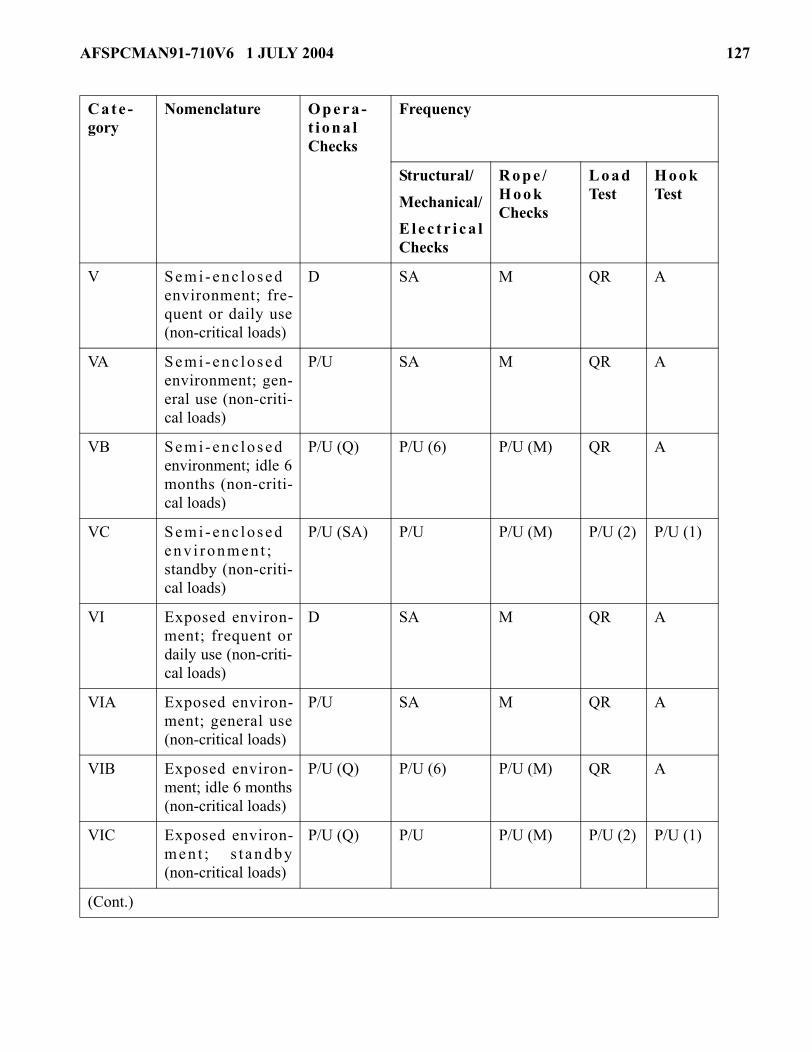
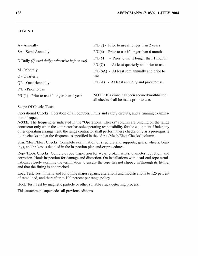
Attachment 6— OVERHEAD CRANES / HOISTS INSPECTION AND TEST SCHEDULE 125
Table A6.1. Inspection and Test Schedule. ................................................................................... 125
Attachment 7— RANGE SAFETY LAUNCH COMMIT CRITERIA 129
Figure A7.1. Instantaneous Critical Electric Field (Ec) Versus Altitude. ....................................... 139
10 AFSPCMAN91-710V6 1 JULY 2004
CHAPTER 1
INTRODUCTION
1.1. Applicability. All Range Users operating on the AFSPC ranges are subject to the requirements ofthis volume to ensure that operations are conducted safely. Air Force Occupational Safety and Health(AFOSH) standards do not apply to contractors or contractor employees except where Air Force person-nel or property are endangered or if specifically required by the contract.
1.2. Organization of the Volume:
1.2.1. Main Chapters. The main chapters of this volume include common requirements for all vehi-cle classes. Appendixes include additional requirements to supplement the main chapters.
1.2.2. Open Text. The open text contains the actual mandatory performance-based requirements. Theonly tailoring expected for these requirements would be the deletion of non-applicable requirements.For example, solid rocket motor performance requirements would be deleted for launch systems thatdo not use solid rocket motors.
1.2.3. Bordered Paragraphs:
1.2.3.1. Bordered paragraphs are non-mandatory and are used to identify some of the potentialdetailed technical solutions that meet the performance requirements. In addition, the borderedparagraphs contain lessons learned from previous applications of the performance requirement,where a certain design may have been found successful, or have been tried and failed to meet therequirement. These technical solutions are provided for the following reasons:
1.2.3.1.1. To aid the tailoring process between Range Safety and Range Users in evaluating apotential system against all the performance requirements.
1.2.3.1.2. To aid Range Safety and Range Users in implementing lessons learned.
1.2.3.1.3. To provide benchmarks that demonstrate what Range Safety considers an accept-able technical solution/implementation of the performance requirement and to help convey thelevel of safety the performance requirement is intended to achieve.
1.2.3.2. The technical solutions in the bordered paragraphs may be adopted into the tailored ver-sion of the requirements for a specific program when the Range User intends to use that solutionto meet the performance requirement. At this point, they become mandatory requirements toobtain Range Safety approval. This process is done to:
1.2.3.2.1. Provide an appropriate level of detail necessary for contractual efforts and to pro-mote efficiency in the design process.
1.2.3.2.2. Avoid contractual misunderstandings that experience has shown often occur if anappropriate level of detail is not agreed to. The level of detail in the bordered paragraphs isnecessary to avoid costly out-of-scope contractual changes and to prevent inadvertently over-looking a critical technical requirement.
1.2.3.3. The Range User always has the option to propose alternatives to the bordered paragraphsolutions. Range User proposed alternative solutions shall achieve an equivalent level of safety
AFSPCMAN91-710V6 1 JULY 2004 11
and be approved by Range Safety. After meeting these two requirements, the Range User pro-posed solutions become part of the tailored AFSPCMAN 91-710 for that specific program.
1.2.3.4. Range Safety has final decision authority in determining whether Range User proposeddetailed technical solutions meet AFSPCMAN 91-710 performance requirements.
1.3. Compliance Documents. Occupational Safety and Health Administration (OSHA) (29 CFR), Envi-ronmental Protection Agency (EPA) (40 CFR), Department of Transportation (DOT) (49 CFR), AFOSH,Air Force instructions (AFIs), and industry standards are specified as compliance documents throughoutthis volume. When there is a conflict between federal regulations, industry standards, and other require-ments, the more stringent requirement shall be used.
12 AFSPCMAN91-710V6 1 JULY 2004
CHAPTER 2
RESPONSIBILITIES AND AUTHORITIES
2.1. Range Safety, 45 and 30 Space Wings. Unless otherwise noted, all references to Range Safety inthis volume refer to the Systems Safety organizations of the 30 and 45 Space Wings. The Range Safetyoffices are responsible for the review and approval of all hazardous and safety critical procedures andoperations at the ER and WR, other than those limited to complex safety, in accordance with the require-ments of this volume. Specific responsibilities of Range Safety include the following:
2.1.1. Review and Approval. Reviewing and approving:
2.1.1.1. Operations Safety Plans (OSPs).
2.1.1.2. Ground Operations Plans (GOPs).
2.1.1.3. Danger Area Information Plans (DAIPs).
2.1.1.4. Facility Emergency Operating Plans (FEOPs) other than those limited to complex safety.
2.1.1.5. Launch Complex Operations Safety Program Plans (LCOSPPs).
2.1.1.6. Other documents as specified in this document.
2.1.1.7. During the review and approval process, both Range Safety and the Range User shallassure timely coordination with other Wing agencies as appropriate. Other Wing agencies include,but are not limited to, Pad Safety, Medical, Civil Engineering, and the Fire Department.
2.1.2. General:
2.1.2.1. Ensuring that hazardous and safety critical facilities are periodically inspected asrequired.
2.1.2.2. Monitoring hazardous and safety critical operations.
2.1.2.3. Defining the threat envelopes of all hazardous operations that may effect public safety orlaunch base safety and establishing safety clearance zones.
2.1.3. Pad Safety. Although the following are not Range User requirements, it is intended that theRange User be familiar with some of the key responsibilities of the Pad Safety function as they relateto the Range User's safety requirements. Pad Safety functions are performed by the 30 SW GroundSafety organization and by a contractor at the 45 SW. NOTE: Unless otherwise noted, these twogroups (Ground Safety (30 SW) and contractor (45 SW)) shall be referred to as Pad Safety in this vol-ume.
2.1.3.1. General Responsibilities. Pad Safety shall participate in meetings and events as directedby Range Safety, including the following.
2.1.3.1.1. Observe, evaluate, and enforce compliance of Range Safety requirements by allpersonnel within the launch complexes, assembly and checkout areas, propellant and ordnancestorage areas, and other areas as deemed appropriate by Range Safety. Note: Pad Safety per-sonnel shall not be denied access to any area where hazardous operations are conducted.
2.1.3.1.2. Review and provide comments on hazardous procedures to Range Safety.
2.1.3.1.3. Review and provide comments on system design data and operating procedures.
AFSPCMAN91-710V6 1 JULY 2004 13
2.1.3.1.4. Implement specified safety precautions and impose safety holds, when necessary,during ground operations, as required by procedures or OSP.
2.1.3.1.5. Assist in the resolution of safety problems in areas where Pad Safety has jurisdic-tion.
2.1.3.1.6. Attend meetings and conferences that involve safety working groups and facilityworking groups, technical interchange meetings, etc., as necessary.
2.1.3.1.7. Coordinate with the Radiation Protection Officer (RPO) to ensure enforcement ofthe Radiation Control Program in all areas where launch vehicles, payloads, and their relatedhazards are located.
2.1.3.1.8. Coordinate with Bioenvironmental Engineering and Environmental Health (bothHealth Physics and Industrial Hygiene) on environmental health hazards.
2.1.3.1.9. Notify Environmental Health, Range Safety, Range Scheduling (30 SW), and CapeSupport (45 SW) immediately anytime an incident involves an environmental health hazard.
2.1.3.1.10. When present, Pad Safety shall ensure the evacuation of personnel from launchcomplexes and facilities and operations are halted when a lightning hazard is imminent inaccordance with the various safety plans.
2.1.3.1.11. Respond to mishaps and/or incidents in accordance with 30/45 SW OPLANs 32-1.
2.1.3.1.12. Assist Range Users on safety related issues.
2.1.3.2. Hazardous and Safety Critical Pad Support. Pad Safety shall provide oversight of theRange User for the following:
2.1.3.2.1. Ensure compliance with established directives and procedures during hazardousand safety critical operations.
2.1.3.2.2. Assess procedure deviations and resolve with Range Safety, as necessary.
2.1.3.2.3. Ensure the number of personnel is kept to a minimum in designated safety clearancezones in accordance with Range Safety approved procedures. Note: Pad Safety shall beincluded in the maximum allowable manning level, unless Range Safety determines that ade-quate support can be provided from a remote location.
2.1.3.2.4. Ensure a comprehensive safety briefing is conducted and understood by partici-pants prior to the start of a hazardous operation.
2.1.3.2.5. In conjunction with the Range User, control personnel access into safety clearancezones during hazardous operations.
2.1.3.2.6. Advise the operation control authority on whether or not to stop operations when ahazardous condition or a safety compromise exists.
2.1.3.2.7. Allow operations to resume only after the imminent danger no longer exists andsafety requirements are met.
2.1.3.2.8. Pad Safety shall operate the Hazard Monitor System (HMS) console for all Space-craft Processing Integration Facility (SPIF) hazardous operations (45 SW only).
14 AFSPCMAN91-710V6 1 JULY 2004
2.1.3.3. Notifications:
2.1.3.3.1. Immediately notify the appropriate agency (Command Post at the 30 SW and RangeSafety at the 45 SW) of any launch vehicle or payload mishap, hazard, handling malfunction,or other incident creating or contributing to an unsafe condition for personnel or critical hard-ware.
2.1.3.3.2. Verbally notify Range Safety of any violation of this document as soon as possible.If requested by Range Safety, a written report shall be provided to Range Safety within fivecalendar days of the violation. The requirements in 2.1.6.3.2 apply only to the 45 SW.
2.1.3.4. Flight Termination System (FTS) Installation, Checkout, and Status (45 SW Only).
Monitor and verify the installation, checkout, and status of the FTS in accordance with RangeSafety instructions at locations designated by Range Safety, including submarines.
2.1.3.5. Inspections:
2.1.3.5.1. Inspect all explosive areas and facilities at least annually to determine compliancewith the requirements of this document and AFI 91-201, Explosives Safety Standards. Theseduties are performed by SEW at the 30 SW.
2.1.3.5.2. Inspect critical facilities prior to the start of a hazardous operation or as directed byRange Safety.
2.1.3.5.3. Inspect new and modified critical facilities prior to the initial start up operation, pre-pare inspection reports on these facilities, and submit the reports to Range Safety within 15calendar days of the inspection (45 SW only).
2.1.3.5.4. Audit the execution of procedures for handling ordnance, propellant material, andhigh pressure gases performed on CCAFS and VAFB at least quarterly.
2.1.3.5.5. Audit the execution of procedures for handling ordnance, propellant material, andhigh pressure gases performed on down range facilities at least annually.
2.2. Range User Responsibilities. Range Users are responsible for the following:
2.2.1. Range User Control Authority Responsibilities. When certified in accordance with theLaunch Complex Safety Training and Certification Requirements, the control authority is responsiblefor the following. (See Volume 1, Attachment 7 for the Launch Complex Safety Training and Certifi-cation Requirements.) If this option is used, Range Safety shall audit the program on an unannouncedand periodic basis. Range Safety shall perform these duties if a control authority is not qualified.Range Safety can assume these responsibilities for qualified control authorities, if requested.
2.2.1.1. Reviewing and approving all procedures relating to the performance of any hazardousoperation and safety critical operation that are limited to launch complex safety. This does notinclude maintenance and testing required by this volume and Volume 3. These procedures stillshall be reviewed by Range Safety.
2.2.1.2. Reviewing and approving Emergency Evacuation Plans (EEPs) and Facility EmergencyOperating Plans (FEOPs) that are limited to launch complex safety.
AFSPCMAN91-710V6 1 JULY 2004 15
2.2.1.3. Where the hazard is limited to launch complex safety or to the defined geographic areasspecified in the Range User’s safety control authority per the LCOSPP, ensuring facilities areinspected in accordance with 5.8.3.1 of this volume.
2.2.1.4. Monitoring hazardous and safety critical operations that are limited to launch complexsafety or to the defined geographic areas specified in the Range User’s control authority per theLCOSPP, as required.
2.2.1.5. Defining the threat envelopes of all hazardous operations limited to launch complexsafety or assigned facilities (the defined geographic area specified in the Range User’s safety con-trol authority per the LCOSPP) and establishing safety clearance zones to protect launch complexpersonnel and resources.
2.2.1.6. Reviewing Range User training plans to ensure that all personnel performing hazardousoperations that are limited to defined geographic areas specified in the Range User’s LCOSPP areprovided adequate training to conduct their jobs and tasks properly.
2.2.1.7. Ensuring that adequate PPE required to comply with approved procedures, OSPs, FSDPs,and GOPs is available to all personnel entering the defined areas specified in the Range User’sLCOSPP.
2.2.1.8. Coordinating with and supporting Pad Safety in carrying out Pad Safety required inspec-tions.
2.2.2. Conduct of Operations:
2.2.2.1. Planning and conducting hazardous and safety critical operations in accordance withRange Safety approved procedures.
2.2.2.2. Planning and conducting operations in accordance with the current edition of the applica-ble OSP for the launch complex, facility, or area in use, including ordnance and propellant opera-tions and areas.
2.2.2.3. Planning and conducting other operations in accordance with the current edition of othersafety plans, as applicable.
2.2.3. Notification of Hazardous and Safety Critical Operations to Range Agencies:
2.2.3.1. Notifying Cape Support (853-5211) for the ER and Range Scheduling (606-8825) for theWR at least 24 hours before the start of any hazardous or flight termination system (FTS)-relatedoperation. The following information shall be provided: date, time, nature of the operation, loca-tion, and procedure or task number.
2.2.3.2. Notifying Range Safety and Pad Safety of all hazardous and safety critical operations andtests including FTS-related operations.
2.2.3.3. Notifying Range Safety and Pad Safety at least 30 calendar days before the schedulederection of a launch vehicle and/or payload.
2.2.4. Document Preparation and Maintenance:
2.2.4.1. Developing and implementing a Ground Operations Plan (GOP) in accordance withAttachment 1 of this volume to cover operations conducted on the ranges.
16 AFSPCMAN91-710V6 1 JULY 2004
2.2.4.2. Developing and implementing procedures and general instructions to cover all operationsconducted on the ranges.
2.2.4.3. Developing, obtaining Range Safety approval, and implementing procedures related tohazardous and safety critical operations.
2.2.4.4. Obtaining Range Safety approval of new procedures or revisions to previously approvedprocedures when there is an impact to the safe conduct of the procedure.
2.2.4.5. Developing and implementing a program to control hazardous energy sources by lockingand tagging in accordance with lockout/tagout approved procedures.
2.2.4.6. Developing, obtaining Range Safety approval, and implementing a propellant off-loadplan and procedure.
2.2.4.7. Developing, obtaining Range Safety approval, and implementing an EmergencyResponse Plan (ERP) for graphite/epoxy composite overwrapped and Kevlar-wrapped pressurevessels.
2.2.4.8. Developing, implementing, and maintaining records for an In-Service Inspection (ISI)Plan in accordance with the requirements of this volume and Volume 3.
2.2.4.9. Developing, implementing, and maintaining records for a Nondestructive Examination(NDE) Plan in accordance with the requirements of this volume and Volume 3.
2.2.4.10. Developing, implementing, and maintaining records for a recertification program forground pressure vessels in accordance with ESMC TR-88-01, A Guide for Recertification ofGround Based Pressure Vessels and Liquid Holding Tanks.
2.2.4.11. Developing and maintaining hazardous facility inspection records and submittingreports to Range Safety, as required.
2.2.4.12. Developing and implementing a Ground System Test Plan for ordnance facilities andareas, as required.
2.2.4.13. Obtaining Base Civil Engineering approval for compliance with AFI 32-2001, The FireProtection Operations and Fire Prevention Program.
2.2.4.14. Obtaining 45 MDG or 30 MDOS approval for procedures in accordance with 45 SWI40-201, Radiation Protection Program or 30 SW1/Sup1 Radiation Protection Plan, supplementto AFI 91-110, Nuclear Safety Review and Launch Approval for Space or Missile Use of Radio-active Material and Nuclear Systems.
2.2.4.15. Preparing and maintaining OSPs as needed and directed by Range Safety, this functionis accomplished by Pad Safety at the 45 SW..
2.2.4.16. Developing, obtaining Range Safety approval, and implementing a Dual Crane LiftPlan, if required.
The designation of a procedure as "Hazardous" or "Non-Hazardous" is evaluated on a case-by-case basis and does not necessarily result in mandatory Pad Safety coverage of the operation. The require-ments for hazardous procedures may be found in Attachment 2 of this volume.
AFSPCMAN91-710V6 1 JULY 2004 17
2.2.4.17. Developing and implementing a training plan for all Range User personnel performinghazardous and safety critical procedures and operations and submitting an outline of this trainingplan to Range Safety for approval.
2.2.4.18. Developing pathfinder requirements in coordination with Range Safety.
2.2.4.19. At the WR, developing, obtaining 30 SW Range Safety approval, and implementing a30 SW First Use Tag Program for lifting hardware at the WR.
2.2.5. Operational Duties:
2.2.5.1. Ensuring required support and emergency elements approved by Pad Safety have contin-uous access to any area where hazardous conditions could occur.
2.2.5.2. Obtaining Pad Safety concurrence to proceed before starting any hazardous and safetycritical operations and before resuming any operation that has been interrupted resumes.
2.2.5.3. Before initiating hazardous or safety critical operations, the following shall be accom-plished:
2.2.5.3.1. Pre-operation and shift change briefings.
2.2.5.3.2. Pre-operation and shift change inspections to verify proper system, facility, and areaconfiguration; personnel and equipment support; and use of a Range Safety approved proce-dure.
2.2.5.4. Maintaining an accurate written or computerized log of events during launch countdownfor three years or three launches, whichever is greater.
2.2.5.5. Observing, evaluating, and enforcing compliance with Range Safety requirements by allpersonnel within launch complexes, assembly, and checkout areas, propellant and ordnance stor-age areas, and other areas as deemed appropriate by Range Safety.
2.2.5.6. Reviewing and providing comments on hazardous and safety critical procedures to RangeSafety.
Range Safety will only evaluate the training plan for areas that could lead to a mishap caused by inade-quate training and could affect workers of other employers, range assets, and the general public.
Interruptions include such events as a safety hold, shift change, evacuation, or breaks.
18 AFSPCMAN91-710V6 1 JULY 2004
CHAPTER 3
GROUND OPERATIONS POLICIES
3.1. Personnel Safety. It is the policy of the ranges that all personnel shall be protected during the perfor-mance of operations.
3.2. Stopping Unsafe Operations:
3.2.1. The following personnel have authority to immediately stop operations or practices that, ifallowed to continue, could reasonably be expected to result in death or serious physical harm to per-sonnel or major system damage:
3.2.1.1. A Safety representative.
3.2.1.2. Any operational supervisor.
3.2.1.3. Personnel in the chain of command who exercise supervisory authority.
3.2.2. These personnel are authorized to stop operations or practices when imminent danger cannotbe eliminated through regular channels. Personnel observing an unsafe operation or practice shallreport their observations to one of these individuals.
3.2.3. Notification of Action. Any action taken by any of the individuals as authorized above to stopan unsafe operation where imminent danger is involved shall be followed by direct verbal, telephone,or radio communication and notification to Pad Safety at the ER and Range Safety at the WR, theSquadron Commander, the Group Commander, or their designated representative.
3.2.4. Notification of Work Stoppage. The Air Force Contracting Officer or Administrator for an AirForce Construction Contract shall be immediately notified of any work stoppage.
AFSPCMAN91-710V6 1 JULY 2004 19
CHAPTER 4
DOCUMENTATION REQUIREMENTS
4.1. Ground Operations Plans. GOPs shall be developed in accordance with the requirements inAttachment 1 of this volume and submitted to Range Safety for review and approval.
4.1.1. The GOP provides a detailed description of hazardous and safety critical operations for pro-cessing aerospace systems and their associated ground support equipment (GSE). Along with the Mis-sile System Prelaunch Safety Package (MSPSP), the GOP is the medium from which missile systemprelaunch safety approval is obtained.
4.1.2. Preliminary drafts shall be provided 45 days before the Conceptual Design Review (cDR), Pre-liminary Design Review (PDR), and Critical Design Review (CDR) but no later than one year beforethe projected date the hardware will arrive at the ranges.
4.1.3. The final GOP shall be submitted 45 calendar days before hardware delivery to the ranges.
4.1.4. The GOP shall be approved before the start of any hazardous operations.
4.2. Test and Inspection Plans. Test and inspection plans shall be developed to document the initial andrecurring validation of component compliance and assessment of hazards. Test and inspection plans shallbe developed for the following items that include, but are not limited to, material handling equipment,ground support pressure vessels, and ground support propellant systems. Specific requirements for eachof these systems are discussed in this volume.
4.2.1. Equipment and System Logs and Test Records:
4.2.1.1. Unless otherwise specified in a separate part of this volume that addresses a particularclass of system or equipment, logs and test records shall be maintained on critical ground supportsystems and major fixed equipment. Logs and test records shall comply with the following:
4.2.1.1.1. Logs and test records shall contain chronological entries including:
4.2.1.1.1.1. Records of use or running time.
4.2.1.1.1.2. Maintenance.
4.2.1.1.1.3. Modifications.
4.2.1.1.1.4. Tests, inspections, acceptable parameters, and results.
4.2.1.1.2. Discrepancies and out of specification results shall be clearly identified.
4.2.1.1.3. Resolution of discrepancies and out of specification results shall be noted.
4.2.1.2. Logs and test records shall be maintained for the life of the system/equipment.
4.2.1.3. Logs and test records shall be available to Range Safety upon request.
4.2.2. Hazardous Facility Inspection Records and Reports. Unless otherwise specified in a sepa-rate part of this volume that addresses a particular class of facility, inspection records of hazardousfacilities shall comply with the following:
4.2.2.1. Hazardous facility inspection records shall be maintained by Facility Operators and/orRange Users in accordance with AFMAN 91-201, Explosives Safety Standards, AFI 91-202, The
20 AFSPCMAN91-710V6 1 JULY 2004
US Air Force Mishap Prevention Program, DoD 6055.9-STD, Ammunition and ExplosivesSafety Standards, and this volume.
4.2.2.2. At a minimum, hazardous facility inspection records shall include discrepancies and dis-crepancy resolution. These records shall be available to Range Safety upon request.
4.2.2.3. Written reports describing actions taken to correct discrepancies shall be submitted toRange Safety within 15 calendar days or less if requested by Range Safety.
4.2.2.4. Explosives Facility and/or Area Ground System Test Plan. A floor plan layout for allexplosives facilities and/or areas showing all grounding system test points shall be developed andmaintained by the Facility Operator and/or the Range User.
4.3. Safety and Emergency Plans:
4.3.1. Operations Safety Plans and Danger Area Information Plans
4.3.1.1. OSP and Danger Area Information Plan Review and Approval:
4.3.1.1.1. At the ER, OSPs (Attachment 3 of this volume) shall be developed by ER PadSafety and submitted to Range Safety for review and approval 30 calendar days before initialuse. Range users shall provide data to Pad Safety for the development of OSPs.
4.3.1.1.2. At the WR, Range Users shall develop their OSPs in accordance with 4.3.1.2 andshall submit the final OSP to Pad Safety no later than 45 days before the start of any hazardousoperation.
4.3.1.1.3. At the ER, Danger Area Information Plans (DAIPs) shall be developed by PadSafety and submitted to Range Safety for review and approval 30 calendar days before initialuse. Range Users shall provide data to Pad Safety for the construction of the DAIPs.
4.3.1.1.4. At the WR, Launch Safety Plans shall be developed by Pad Safety and submitted to30 SW/SE for approval 14 calendar days before initial use.
4.3.1.2. OSP Data Requirements. OSPs shall meet the following requirements:
4.3.1.2.1. OSPs shall be developed for all hazardous operating areas including launch com-plexes and associated areas and facilities.
4.3.1.2.2. OSPs shall be developed for unique, but frequently repeated, operations that requirespecial or detailed safety considerations not addressed in this publication.
4.3.1.2.3. OSPs shall be comprehensive documents intended to clarify and provide detailedsafety requirements that are particular to the operating area or operation in question.
4.3.1.2.4. At a minimum, OSPs shall contain, address, and provide reference to the following:
4.3.1.2.4.1. A scaled map of the operating area that identifies hazardous and safety criticalsystems, locations, or features including, but not limited to, propellant holding areas,explosive storage areas, high pressure vessels, emergency evacuation routes and assemblypoints, safety control areas, warning lights, and first aid rooms.
4.3.1.2.4.2. A matrix list of all hazardous or safety critical systems (fixed and portable)that are or will be in the operating area with designation as affecting public, launch base,
AFSPCMAN91-710V6 1 JULY 2004 21
launch complex, or launch support facility safety, PPE required, and any special safetyrequirements.
4.3.1.2.4.3. A matrix list of all hazardous or safety critical operations or tasks performedin the operating area in order of performance with designation as affecting public, launchbase, launch complex or launch support facility safety; safety clearance zones required;personnel loading requirements; PPE required; any special safety requirements; and iden-tification of those operations or tasks that may be run concurrently.
4.3.1.2.4.4. A complete explanation of all aural/visual warning systems in the operatingarea including the required personnel response.
4.3.1.2.4.5. The safety badging (permit) system at the operating area with details, such asrequirements for obtaining the safety badge, access control, and safety badge types for dif-ferent personnel categories. Range Safety and Pad Safety retain the option to train Safetypersonnel on each launch vehicle payload, system, and launch complex.
4.3.1.2.4.6. Range Users shall provide Range Safety and Pad Safety updated listings ofpermit numbers, names, and assigned agencies 48 hours before all launches.
4.3.1.2.4.7. Visitor safety briefings, including content and responsibility.
4.3.1.2.4.8. Detailed personnel requirements, including, but not limited to, smoking areas,especially in propellant and explosive locations; eating and drinking areas; conduct; han-dling of work clothes due to exposure to hazardous, toxic, or flammable materials; workhour restrictions; and tool tethering requirements.
4.3.1.2.4.9. Fall protection surveys and plans.
4.3.1.2.4.10. PPE details including specific requirements regarding types and usage, espe-cially concerning self-contained atmospheric protective ensemble (SCAPE) and splashsuits, leg and wrist stats, and hard hats.
4.3.1.2.4.11. Training and certification plans.
4.3.1.2.4.12. Detailed procedures for reaction to lightning and high wind warnings.
4.3.1.2.4.13. Detailed procedures for general emergencies such as fire, explosion, andpropellant spills.
4.3.1.2.4.14. Detailed procedures for natural disasters such as hurricanes, tornadoes, orearthquakes.
4.3.1.2.4.15. Mishap reporting and emergency response phone numbers, including imme-diate notification to the Pad Safety Officer (PSO) or Operations Safety Technician (OST)of any personnel injury or resource damage.
4.3.1.2.4.16. FEOPs.
4.3.1.2.4.17. Emergency Evacuation Plans (EEPs).
4.3.1.2.4.18. Lockout/tagout plans and procedures.
4.3.1.2.4.19. Confined space operations surveys, plans, and procedures.
4.3.1.2.4.20. Hot work plans and procedures.
22 AFSPCMAN91-710V6 1 JULY 2004
4.3.1.2.4.21. Self-inspection program and inspection schedules.
4.3.2. Facility Emergency Operating Plans. FEOPs shall be developed by facility operators andsubmitted to Range Safety for review and approval at least 45 calendar days before facility use.FEOPs describe necessary measures to assure safety of personnel, government resources, and opera-tions essential to establish safe conditions. Conditions that should be addressed in the FEOPs include,but are not limited to, response to fire and response to spill, leak, or release of hazardous commodities.Topics that should be addressed in FEOPs include notifications and announcements, safing of sys-tems, evacuation routes, and EEAP locations. FEOPs are typically combined as a subset of anotherpublication such as an Operations Safety Plan, but this format is not a requirement. The Range Safetyoffices are available to provide guidance if required by the Range User.
4.3.3. Emergency Evacuation Plans:
4.3.3.1. EEPs detailing safety and emergency actions shall be developed by facility operators andposted in every building, facility, and area.
4.3.3.2. EEPs shall include the following information:
4.3.3.2.1. Identification of exit/egress routes.
4.3.3.2.2. Identification of primary and alternate Emergency Evacuation Assembly Points(EEAPs); EEAPs shall be designated by signs.
4.3.3.2.3. Responsibilities of supervisors and personnel for duties assigned in an emergency.
4.3.3.2.4. Actions to be taken to safe an operation.
4.3.3.2.5. Methods of communication including aural warning systems and public address(PA) announcements.
4.3.3.2.6. Location of fire alarm boxes and other emergency activation devices.
4.3.3.2.7. Required emergency equipment and PPE.
4.3.3.2.8. Required personnel training.
4.3.3.2.9. Reporting requirements such as, but not limited to, Squadron Commander or Com-mand Post.
4.4. Procedures:
4.4.1. General Requirements for Procedures:
4.4.1.1. Procedures and general operating instructions for all operations conducted on the rangesshall be developed.
4.4.1.2. All procedures shall be written in accordance with the requirements provided in Attach-ment 2 of this volume.
4.4.1.3. Brief summaries of all procedures shall be submitted as part of the GOP review andapproval process. At that time, the operating procedure summaries shall be designated as “Hazard-ous,” “Non-Hazardous,” or “Safety Critical.” These designations shall be justified in the operatingprocedure summaries. Range Safety may designate additional processes and operations as “Haz-ardous” or “Safety Critical.”
AFSPCMAN91-710V6 1 JULY 2004 23
4.4.1.4. Revisions to any procedures shall be submitted to Range Safety for review and approvalwhen there is a potential impact on the safe conduct of an operation.
4.4.2. Hazardous and Safety Critical Procedures:
4.4.2.1. Procedures for hazardous and safety critical operations shall be developed in accordancewith the requirements in Attachment 2 of this volume. Emergency actions shall be included in theprocedures. Approval of hazardous and safety critical procedures shall not be given until the per-tinent data sections of the MSPSP and GOP have been reviewed and approved.
4.4.2.2. Disapproval of a formally submitted procedure may result in an additional 30 calendarday (45 calendar days for new programs) review time submittal and possible delay of operations.Range Users new to the ranges are encouraged to provide a draft of a typical procedure for earlyreview.
4.5. Range User Training Plan. A training plan listing all training courses used for personnel involvedwith hazardous or safety critical operations and procedures shall be submitted to Range Safety as part ofthe GOP.
4.6. Mishap Reporting:
4.6.1. Mishaps Involving Air Force Personnel and Property. Reporting criteria for mishapsinvolving Air Force personnel and property are established in AFI 91-204, Safety Investigations andReports. Mishaps involving radioactive materials shall be reported in accordance with AFI 91-110.
4.6.2. Accident Notification Plan. An Accident Notification Plan shall be developed by the RangeUser and coordinated with Range Safety (ER)/Pad Safety (WR) to ensure proper and timely notifica-tion of mishaps. The plan shall be included in the GOP.
24 AFSPCMAN91-710V6 1 JULY 2004
CHAPTER 5
GROUND OPERATIONS SAFETY REQUIREMENTS
5.1. Ground Operations Personnel Requirements:
5.1.1. Personnel Training, Certification and Experience. A list of personnel training, certification,and experience requirements shall be available as part of the Range User training plan.
5.1.2. Ground Operations Safety Orientation and Training:
5.1.2.1. All Range Users shall ensure that their personnel receive formal safety, fire prevention,and occupational health orientation and training before receiving a controlled area badge. Theemployer is responsible to ensure the training is adequate and complete.
5.1.2.2. Unique personnel training and certification requirements for hazardous operations suchas ordnance, crane operations, forklift operations, and SCAPE shall be specified in the appropriateprocedures.
5.1.3. Personnel Conduct:
5.1.3.1. Food, Beverage, and Cigarette Consumption. Range Users shall ensure that eating,drinking, or smoking is authorized only in designated areas.
5.1.3.2. Alcoholic Beverages and Narcotics:
5.1.3.2.1. Range Users shall ensure that the use of alcoholic beverages and narcotics while onduty is prohibited.
5.1.3.2.2. Range Users shall require that their personnel taking prescription or non-prescrip-tion medications that could affect performance notify their supervisor.
5.1.3.3. Mischief. Range Users shall ensure that their personnel are prevented from indulgence inpractical jokes, horseplay, scuffling, and wrestling.
5.1.4. Work Time Restrictions:
5.1.4.1. Range User supervisors at all levels shall ensure their personnel will not be assigned to,and will not participate in, critical operations if it is evident that their physiological or psycholog-ical well being is, or is likely to be, adversely affected by immunizations, fatigue, blood donations,use of drugs, illness, consumption of alcohol, or other stress conditions.
5.1.4.2. Each duty period for mission ready (Category A) and mission support (Category B) per-sonnel, including participation in a launch or launch attempt activity, shall be preceded by anavailable rest period.
5.1.4.3. Planned duty for personnel in either mission ready or mission support should normally be8 hours, starting when the individual reports for duty. Those personnel identified to support oper-ational tests shall not be scheduled for duty during the planned rest period.
5.1.4.4. Hazardous Operations and Prelaunch Attempts. The following criteria shall be used fordetermining hours worked versus rest time for all personnel who work with hazardous systems,materials, or components, or who accomplish prelaunch functions that require a high degree ofconcentration:
AFSPCMAN91-710V6 1 JULY 2004 25
5.1.4.4.1. Maximum 12-hour shift, unless approved by Range Safety or a USAF SquadronCommander, with at least 8 hours of rest after 12 hours of work.
5.1.4.4.2. A maximum of 60 hours per week.
5.1.4.4.3. A maximum of 14 consecutive days.
5.1.4.5. Consecutive Launch Attempts:
5.1.4.5.1. When 12-hour shifts are required and launches are rescheduled on a 24-hour basis,consideration shall be given for a 48-hour launch delay after 3 consecutive back-to-backlaunch attempts.
5.1.4.5.2. In the event mission impacts or operational requirements necessitate 12-hour shifts,mission ready personnel shall not be scheduled for more than 5 consecutive shifts without a48-hour break and mission support personnel shall not be scheduled for more than 6 consecu-tive shifts without a 24-hour break.
5.1.4.5.3. Mission Ready Crew Rest Waiver Authority. Crew rest and/or rest period require-ments for mission ready (Category A) personnel can only be waived by the Chief of Safety orthe Space Wing Commander.
5.1.4.6. 30 SW Additional Work Restrictions:
5.1.4.6.1. In the event of a missile accident, emergency, or operational necessity, the duty timelimits defined in this volume may be exceeded with the expressed knowledge of the 30 SWCommander or Vice Commander, commanders of tenant organizations, or the 30 SW Chief ofSafety for personnel under their respective control.
5.1.4.6.2. When mission requirements dictate, the duty period may be extended to 12 hours bythe first level supervisor. Rest periods and break periods shall be provided according to appro-priate regulations and negotiated agreements.
5.1.4.6.3. If, after a complete evaluation of the potential hazards involved, mission require-ments dictate a duty period in excess of 12 hours, the following criteria shall apply:
5.1.4.6.3.1. For mission ready (Category A) personnel, the duty periods may be increasedto 14 hours or rest periods may be waived with the express knowledge of the 30 SW Com-mander or Vice Commander, WR Commander, Operations Groups Commander, or theChief of Safety.
5.1.4.6.3.2. For mission support (Category B) personnel, the duty period may be increasedto 14 hours with the expressed knowledge of the applicable division chief or equivalentlevel supervisor.
5.2. Hazardous Ground Operations General Requirements:
5.2.1. Pathfinder Requirements:
5.2.1.1. In coordination with the Range User, Range Safety shall determine which proceduresrequire a pathfinder and its necessary fidelity.
5.2.1.2. Before the first use of applicable hazardous procedures, including contingency, such asoperations with live ordnance, pressure systems, or propellant, pathfinder operations shall be con-
26 AFSPCMAN91-710V6 1 JULY 2004
ducted at the ranges using inert or dummy ordnance, non-pressurized systems, or non-fueled sys-tems.
5.2.1.2.1. Handling operations shall be performed with inert or dummy equipment that simu-lates the flight unit in form, fit, function, weight, and center of gravity.
5.2.1.2.2. Pressure and propellant system operations shall be performed with equipment thatsimulates flight equipment valve connections and operations.
5.2.1.2.3. Pathfinder operations shall use GSE that will be used for flight operations.
5.2.1.2.4. Range Safety and the Range User shall jointly develop acceptance criteria for path-finder operations and evaluate whether the acceptance criteria have been met.
5.2.2. Control of Access to Hazardous Operations. The launch complex authority shall establishpersonnel limits, entry control, and control areas for all hazardous operations with Range Safetyapproval.
5.2.2.1. Personnel Limits for Hazardous Ground Operations:
5.2.2.1.1. Personnel limits shall be established for all hazardous operations and tasks andapproved by Range Safety. Deviation from approved access list numbers requires RangeSafety approval.
5.2.2.1.2. The supervisor in charge of the building or operation is responsible for maintainingpersonnel load limits for that building or operation.
5.2.2.2. Control of Access to All Hazardous Operations:
5.2.2.2.1. Hazardous areas shall be fenced, barricaded, or cordoned off and personnel accesscontrol maintained at a central control point.
5.2.2.2.2. Access roads shall be closed by barricades, guards, or signs during hazardous oper-ations for positive control of personnel and vehicles. Emergency vehicles shall not traverse thecontrolled area if another route is available.
5.2.2.2.3. When hazardous operations are covered by Pad Safety, Pad Safety shall controlaccess.
5.2.2.3. Personnel Restrictions for Hazardous Ground Operations:
5.2.2.3.1. Non-essential personnel shall leave hazardous areas (safety clearance zones) beforethe start of operations.
5.2.2.3.2. Whenever a warning light status is changed or an audible signal is sounded, a PAannouncement shall precede it and identify the reason for the change.
5.2.2.3.3. Each facility and/or area shall have instruction signs informing personnel of thearea aural and warning light scheme before entry.
5.2.2.3.4. The buddy system shall be used in all hazardous operations.
5.2.2.3.5. Area Warning Lights. Personnel with the appropriate badge and security clearancehave access to areas in accordance with the following:
AFSPCMAN91-710V6 1 JULY 2004 27
5.2.2.3.5.1. A flashing green light indicates the controlled area is open to normal work.Hazardous commodities may be present in the area but no hazardous operations are inprogress. Access is controlled by Security/Hazardous Support Operations (HOS).
5.2.2.3.5.2. A flashing amber light indicates a hazardous operation is in progress in thecontrolled area. Non-essential personnel shall be cleared from the controlled area. Person-nel shall not enter without permission from Pad Safety or, in the absence of Pad Safety, theentry control authority.
5.2.2.3.5.3. A flashing red light indicates an emergency situation in the controlled area.All personnel shall evacuate the controlled area to the EEAP. This signal shall be accom-panied by the sounding of an audible alarm and a PA announcement. This signal is alsoused to clear all personnel from a launch complex before a launch. At the WR, a flashingred light also designates a dangerous operation for ballistic missile operations; for exam-ple, follow-on test and evaluation (FOT&E) where work is performed under the strict con-trol of technical orders (T.O.s).
5.2.3. Hot Work Operations:
5.2.3.1. Hot Work Operating Standards. Hot work (open flame) operations including welding,soldering, cutting, brazing, grinding, or heating of materials in such a manner as to cause a sourceof ignition shall be conducted in accordance with AFOSHSTD 91-5, Welding, Cutting, and Braz-ing, 29 CFR 1910.252, (Subpart Q, Welding, Cutting and Brazing), General Requirements, andAmerican National Standards Institute (ANSI) Z49.1, Safety in Welding and Cutting.
5.2.3.2. Hot Work Operations Training and Certification. All welders shall be trained andcertified by competent authority to standards no less than those established by the American Weld-ing Society (AWS).
5.2.3.3. Hot Work General Operating Requirements:
5.2.3.3.1. A written permit shall be obtained from the Fire Marshall before performing hotwork.
5.2.3.3.2. Locations where hot work will be routinely performed may operate on an indefinitepermit if that area is subject to periodic Fire Department inspections.
5.2.3.3.3. A fire watch shall be maintained during and after the hot work until such time thefire watch determines that the combustion hazard no longer exists.
5.2.3.3.4. The requirement for the Fire Department to perform the fire watch shall be deter-mined on a case-by-case basis by the Fire Marshall and Range Safety.
5.2.3.3.5. Proper housekeeping and protective shields and barriers shall be used to preventinadvertent combustion.
5.2.3.3.6. Combustibles shall be kept at least 35 feet away from the operation.
5.2.3.3.7. A suitable fire extinguisher shall be available.
5.2.3.4. Hot Work Within Ordnance or Propellant Areas. Hot work within ordnance or pro-pellant areas shall be coordinated with Range Safety or Pad Safety as well as the range FireDepartment.
28 AFSPCMAN91-710V6 1 JULY 2004
5.2.3.5. Hot Work on Containers and Lines That May Have Contained Explosives or Flam-mables. Hot work shall not be performed on containers and lines that may have contained explo-sives or flammables and that have not been properly cleaned and purged.
5.2.4. Control of Hazardous Energy Sources:
5.2.4.1. Hazardous energy sources shall be controlled through a lockout/tagout program that com-plies with the requirements of 29 CFR 1910.147, The Control of Hazardous Energy (Lockout/Tagout), AFOSHSTD 91-501, Air Force Consolidated Occupational Safety Standard, and ANSIZ244.1, Safety Requirements for the Lockout/Tagout of Energy Sources.
5.2.4.2. Lockout/tagout procedures shall be developed by Range Users and approved by RangeSafety (ER)/Pad Safety (WR) per 5.2.4.1.
5.2.5. Confined Space, Tank Entry, and Tank Cleaning:
5.2.5.1. Personnel who enter and work within permit-required confined spaces shall comply withappropriate controls as defined in 29 CFR 1910.146, Permit-Required Confined Spaces, ANSIZ117.1, Safety Requirements for Confined Spaces, and AFOSHSTD 91-25, Confined Spaces.
5.2.5.2. All Range Users, contractors, and subcontractors who will be entering confined spacesother than the contractor’s equipment and flight hardware shall contact Range Ground Safety atthe start of the project to obtain information about the confined space.
5.2.6. Tethering of Equipment:
5.2.6.1. Hand-held tools, equipment, and personal belongings shall be tethered in any area wheredropped objects could pose a hazard to personnel.
5.2.6.2. Hazards to be considered in determining tethering requirements include direct contactwith personnel or the consequences of damaging critical hardware providing the potential of latentor immediate hazards to personnel from damaged hardware.
5.3. Personal Protective Equipment:
5.3.1. Range User Responsibilities. The Range User shall provide the applicable PPE required forthe work location that meets the requirements established by 29 CFR 1910.132, (Subpart I-PersonalProtective Equipment), General Requirements, 29 CFR 1910.133, Eye and Face Protection, 29 CFR1910.134, Respiratory Protection, 29 CFR 1910.135, Head Protection, 29 CFR 1910.136, Foot Pro-tection, California Occupational Safety and Health (CAL-OSHA) (WR only), AFOSHSTD 91-501,ANSI, and National Institute of Occupational Safety and Health (NIOSH).
5.3.2. PPE Compatibility. All PPE shall be compatible with the hazardous materials involved andshall be subject to approval by Range Safety and Bioenvironmental Engineering.
5.3.3. Clothing Requirements in Industrial and Missile Operating Areas:
5.3.3.1. Complete upper and lower body attire shall be worn in industrial and missile operatingareas. Lower arms, hands, and head do not have to be covered unless otherwise stated.
5.3.3.2. Open-toed and high-heeled shoes are prohibited.
5.3.3.3. Canvas shoes are not permitted where liquid propellants or cryogenics are handled.
5.3.3.4. Dresses and shorts shall not be worn on towers.
AFSPCMAN91-710V6 1 JULY 2004 29
5.3.3.5. The appropriate attire for hazardous and safety critical operations shall be identified inthe operating procedure.
5.3.3.6. Coveralls or other work clothes designated to be worn in toxic propellant areas shall notbe worn in eating areas or other facilities off site.
5.3.3.7. Expended work clothes shall be clearly segregated from work clothes ready for use.
5.3.3.8. Work clothes exposed to an oxygen-rich atmosphere shall be thoroughly aired beforesmoking is allowed.
5.4. Fall Protection. The Range User shall observe and use applicable industry standards for fall protec-tion (such as guard rails, lanyard anchorages, lanyards, snap hooks, ladders, inspections). Specific criteriafor the equipment listed above can be found in ANSI Z359.1, Personnel Fall Arrest Systems, Sub-systems, and Components; ANSI A10.14, Construction and Demolition Operations - Requirements forSafety Belts, Harnesses, Lanyards and Lifelines for Construction and Demolition Use; AFOSHSTD91-501; 29 CFR 1910.23, Guarding Floor and Wall Openings and Holes; 29 CFR 1910.27, Fixed Lad-ders; and 29 CFR 1926.105, Safety Nets.
1. Fall Hazards:
a. All open-sided floors or fall hazards over 4 feet or any height where falls into hazards such as mov-ing machinery, impaling, or drowning hazards exist should be guarded by standard guard rails with mid-rails and toe boards.b. Fall protective PPE should be used when installing guardrails, safety nets, and other fall protection.
2. Hazard Guards. If standard guard rails are not installed, PPE, in the order of preference listed below, should be used to protect personnel if they are within 6 feet of the hazard:
a. Full body harness (ANSI Class III).b. Chest harness (ANSI Class II).c. Safety nets (29 CFR 1926.105).
3. PPE Lanyards. PPE should be attached to anchorages by a lanyard that limits the length of a fall to no more than 6 feet. The order of preference is as follows:
5.5.1. The Range User shall observe and use applicable industry standards for smoking areas. Nosmoking signs shall be posted as directed by the range Fire Department.
4. Lanyard Anchorages:
a. Handrails should not be used for anchorages or lanyard tie-off points.b. Life line (dog-run) style anchorages for lanyards require specific approval by Range Safety for each application. Appropriate justification with analysis must be submitted for Range Safety approval. Dog-runs are not an acceptable alternative to installed platforms or walkways.
5. Installation of Permanent Anchorage Connectors:
a. Visual inspection of installed permanently fixed anchorage connections and dog-runs should be accomplished annually by the Range User. Documentation should be available for review by Range Safety.b. Suspect connections or anchorages should receive NDE as determined by Range Safety and should be repaired or replaced as required.
6. Fall Protection Snap Hooks. Fall protection snap hooks used in fall protection systems should be sized to ensure proper connection.
7. Fall Protection Equipment Inspections:
a. Each article of PPE should be visually inspected by the user before use.b. All PPE should be thoroughly inspected at least twice a year by a qualified person of the organization that owns the PPE.c. Each piece of PPE should have a visible tag or other indication of inspection permanently attached with the following information: i. The date inspected. ii. The next inspection due date. iii. The stamp or signature of the quality inspector.
8. Ladder Fall Protection:
a. Ladder fall protection should be installed on all fixed ladders with a fall hazard of 20 feet or more.b. Ladder safety devices with body belts should be the preferred method of fall protection.
Selection of designated smoking areas, their ash receptacles, and ventilation systems is subject to the review and approval of the Fire Department. No smoking and smoking areas in the complex should be clearly designated by lines painted on the concrete or asphalt surfaces and appropriately marked by signs.
AFSPCMAN91-710V6 1 JULY 2004 31
5.5.2. Designated Non-Smoking Areas. Smoking is prohibited at all times and flame-producingdevices shall be prohibited within the following areas:
5.5.2.1. Within 100 feet of any propellant storage tank.
5.5.2.2. On gantries or service towers.
5.5.2.3. Within 100 feet of the test stand while propellants are being transferred or during the timepropellants are aboard the launch vehicle and/or payload.
5.5.2.4. In the vicinity of the launch vehicle and/or payload during and after ordnance installation.
5.5.2.5. In missile impact areas where radioactive contamination, ordnance, or fuels are present.
5.5.2.6. In any area displaying NO SMOKING signs.
5.5.2.7. In all propellant operating and storage areas except in specifically designated smokingareas.
5.6. Operating Restrictions Due to Lightning:
5.6.1. General. Conditions under which launch complexes, launch vehicle and payload assemblyareas, and other hazardous areas shall be cleared due to a threat of lightning shall be specified in theOSP
5.6.2. ER Lightning Hazard Watches and Hazard Warnings:
5.6.2.1. Operations that will be allowed during lightning watches and warnings shall be coordi-nated, reviewed, and approved by 45 SW/SES and documented in the specific OSP.
5.6.2.2. Phase I Lightning Watch. For the 5 nautical miles lightning watch (Forecast for lightningwithin 5 nautical miles of centroid of a specific lightning alert area, [Space Launch Complex(SLC) and/or facility], expected within some time, usually 30 minutes), the following actions shallbe taken:
5.6.2.2.1. SCAPE operations, propellant tanking and detanking, hoisting hazardous materialsor 1.1 to 1.4 class ordnance, and other hazardous operations that take 30 minutes or longer tosecure shall not be started.
5.6.2.2.2. If an operation is in progress, personnel shall begin safing the system so as to havethe area secured and evacuated, if required, before the forecasted 5 nautical miles lightningwarning start time.
5.6.2.3. Phase II Lightning Warning. For the lightning warning, lightning is imminent or occur-ring within the 5 nautical mile boundary of a centroid of a specific lightning alert area (SLC and/or facility), the following actions shall be taken:
5.6.2.3.1. All operations shall cease unless they are performed remotely and have beenapproved by either Range Safety or are authorized in the specific OSP.
5.6.2.3.2. If the Phase I lightning watch has not been previously announced or the 5 nauticalmile lightning warning start time is earlier than forecast, the operation shall be terminated atthe safest step and the area secured and evacuated in accordance with the specific OSP.
5.6.2.4. Due to the differences between launch vehicle configurations and SLCs, evacuationrequirements shall be specified in each specific OSP. In general, the complex shall be cleared
32 AFSPCMAN91-710V6 1 JULY 2004
before the 5 nautical mile lightning warning start time whenever a launch vehicle with payload,propellants, solid rocket motors, or Class 1.1 to 1.4 ordnance is present or EEDs are electricallyconnected.
5.6.2.5. Additional information regarding lightning hazard watches and warnings may be foundin the 45 SW OPLAN 15-1, Weather Operations Plan.
5.6.3. WR Lightning/Thunderstorm Watches and Warnings. The 30th Weather Squadron issuestwo messages related to lightning/thunderstorms: A watch and a warning.
5.6.3.1. A Lightning/Thunderstorm Watch is a forecast issued when the potential for lightning/-thunderstorms is expected to occur within 10 nautical miles of any location on VAFB. Thedesired lead time for this watch is 2 hours. The watch is forecast for a period of time (valid time)that lightning/thunderstorms are expected to be within 10 nautical miles.
5.6.3.2. A Lightning/Thunderstorm Warning is issued when lightning is observed within 10 nau-tical miles of VAFB.
5.6.3.3. Meteorological and weather warning notification procedures are provided in 30 SWI15-101, Weather Support.
5.6.3.4. Upon issuance of the Lightning/Thunderstorm Watch, all operations involving propellantor ordnance activities shall be completed before the start of the Lightning/Thunderstorm Watch“valid time.” All propellant or ordnance activities not completed before the watch “valid time,”may continue if the facility has a certified lightning protection system and the organization’s com-mander grants approval to continue. All other non-propellant or non-ordnance activities may con-tinue in the facility during the Lightning/Thunderstorm Watch.
5.6.3.5. Upon issuance of the Lightning/Thunderstorm Warning, a space launch complex, explo-sive/missile processing facility, launch facility, storage facility, or any other hazardous operatinglocation that has a certified lightning protection system does not require evacuation; and allnon-propellant or non-ordnance activities may continue in the facility during the Lightning/Thun-der- storm Warning. Exception: If either of the following conditions apply, all personnel shallevacuate to at least the public transportation route (PTR) distance regardless of the lightning pro-tection system: Condition 1: There is exposed solid propellant. Condition 2: There is an explosiveinitiation device that cannot be placed in a safe configuration.
5.6.3.6. Upon issuance of the Lightning/Thunderstorm Warning, any operation involving propel-lant or ordnance activities in a space launch complex, explosive/missile processing facility, launchfacility, storage facility, or any other hazardous operating location that does not have a certifiedlightning protection system shall evacuate to at least the PTR distance.
The intent of 5.6.3.4 and 5.6.3.5 is to allow all non-ordnance and non-propellant activities to continue in facilities with certified lightning protection systems during a Lightning/Thunderstorm Watch or Warning. A "certified" lightning protection system is inspected and maintained in accordance with AFI 32-1605 or National Fire Protection Association Standard 780. These are the minimum lightning pro-tection requirements imposed by 30 SW Safety. Range Users may be more conservative at their own discretion.
AFSPCMAN91-710V6 1 JULY 2004 33
5.6.3.7. If a Lightning/Thunderstorm Watch or Warning has not been previously issued or theLightning/Thunderstorm Watch or Warning “valid time” is earlier than forecast, the propellant orordnance activities shall be terminated at the safest point and the area secured.
5.6.3.8. Lightning/Thunderstorm Watch and Warning notifications and Range User actionrequirements for propellant or ordnance activities apply to both day-to-day and day-of-launchoperations.
5.6.3.9. Range Users working an approved operation involving propellant or ordnance activitiesduring a Lightning/Thunderstorm Watch can call 30 WS (x6-8022) to get an update of the statusof the watch. To ensure the consistent and accurate relay of information, Range Users should des-ignate a single point of contact to make these calls, preferably the individual in charge of the oper-ation.
5.7. Operating Restrictions Due to High Winds:
5.7.1. For Winds of 18-29 Knots as Measured on or Closest to Specific Facilities. No work shallbe performed on the exterior surface of umbilical or mobile service towers or other tall structuresunless spider staging or similar suspended work devices are safely secured to the structure.
5.7.2. For Winds of 30 Knots or More as Measured on or Closest to Specific Facilities:
5.7.2.1. No work shall be performed on the exterior surfaces of umbilical or mobile service tow-ers or other tall structures except for emergency tasks.
5.7.2.2. Work performed during emergency conditions shall be approved by Pad Safety or RangeSafety and all suspended work devices shall be secured to the structure.
5.8. Facility Use:
5.8.1. Facility Use General Requirements:
5.8.1.1. Facilities shall be used within the limits of their design. If facilities are leased from theUSAF, the Range User shall coordinate with Range Safety and Civil Engineering for proper usewithin the limits of their design.
5.8.1.2. Only those operations that are consistent with facility design, materials, equipment, andpersonnel shall be performed in the facility.
5.8.2. Hazardous Facility Use General Requirements:
5.8.2.1. The use of facilities for hazardous storage or processing operations shall be approved byRange Safety.
5.8.2.2. The OSP shall be developed by the Range User in coordination with the Pad Safety andshall be approved by Range Safety.
Examples of approved activities are installation of electrical cables, mechanical components, flight hardware, stud standoff, and wing installation. Examples of unapproved activities are handling of rocket motors or launch vehicles by lifting, mating, or roll transfer; fuel transfer and pressurization; and ordnance installation and connection.
34 AFSPCMAN91-710V6 1 JULY 2004
5.8.2.3. Facilities used for hazardous activities shall have an FEOP and an Evacuation Plan devel-oped by facility operators.
5.8.2.4. Simultaneous hazardous operations within the same control area are prohibited.
5.8.2.5. Non-hazardous operations within the same control area as an ongoing hazardous opera-tion are prohibited unless a safe distance approved by Range Safety can be maintained.
5.8.3. Hazardous Facility Inspection:
5.8.3.1. Range User Facility Inspections:
5.8.3.1.1. Facilities shall be inspected before first use, upon modification, before operations,and at least annually, as determined by the Range User and Pad Safety.
5.8.3.1.2. Inspection reports shall be maintained in accordance with AFMAN 91-201, AFI91-202, and DoD 6055.9-STD.
5.8.3.1.3. Actions shall be taken to correct discrepancies identified during inspections.Records of discrepancies and discrepancy corrections shall be maintained for 3 years.
5.8.3.1.4. A verbal report shall be made to Range Safety (ER)/Pad Safety (WR) within thesame day of the inspection if discrepancies are found that may delay a planned operation orendanger personnel or material handling equipment (MHE) used to handle critical hardware,or the critical hardware itself.
5.8.3.1.5. Written reports describing actions taken to correct discrepancies identified duringinspections shall be submitted to Range Safety (ER)/Operations Safety (WR) within 15 calen-dar days or less if deemed necessary by either group.
5.8.3.2. Operations Safety Facility, Complex, and Area Inspections:
5.8.3.2.1. A systematic visual examination of facilities, related GSE, and any work inprogress that could cause accidental damage to property or injury to people or affect the launchschedule shall be performed by Pad Safety. This inspection deals primarily with aerospaceground equipment (AGE), launch critical associated equipment, maintenance, associated hard-ware, fire hazards, fall protection, and equipment on the complex.
5.8.3.2.2. A safety inspection shall be performed on launch complexes, explosives storageand processing facilities and areas, and in hazardous processing and checkout facilities accord-ing to the following schedule:
5.8.3.2.2.1. At least 2 weeks before a launch vehicle or payload being brought to the pador facility.
5.8.3.2.2.2. Within 48 hours of the pad erection day.
5.8.3.2.2.3. Immediately before the start of any hazardous or safety critical operation.
5.8.3.2.2.4. After any major or safety-related modification has been made to facilities orequipment.
5.8.3.2.3. Explosives storage and operating areas and facilities shall be inspected by PadSafety at least annually to ensure compliance with explosives safety criteria. Area monthlyrecords shall be reviewed during the annual inspection.
AFSPCMAN91-710V6 1 JULY 2004 35
5.8.3.3. Facility Operator Inspections. The facility operator shall inspect explosive storage andoperating areas and facilities at least once a month.
5.8.3.4. Facility Spot-Checks. As deemed appropriate by Range Safety, spot-checks of rangefacilities shall be performed to ensure compliance with this publication.
36 AFSPCMAN91-710V6 1 JULY 2004
CHAPTER 6
MATERIAL HANDLING EQUIPMENT, CRANE AND HOIST, PERSONNEL PLATFORM, POWERED INDUSTRIAL TRUCK, AND ELEVATOR OPERATIONS
6.1. Material Handling Equipment Operations. The operations requirements for material handlingequipment (MHE) used for handling (lifting, supporting, or manipulating) critical and non-critical hard-ware are described below. These requirements are applicable to new or modified MHE. The requirementsare also applicable to permanent or short-term use MHE and apply whether the equipment is owned,rented, or leased by the government, contractors, or commercial operators.
6.1.1. MHE Operating Standards:
6.1.1.1. Existing equipment shall not be used in operations unless it meets all the requirements inVolume 3, Chapter 6 unless otherwise agreed to by Range Safety.
6.1.1.2. All MHE shall be operated, tested, and maintained in accordance with the requirementsof this publication, AFOSHSTD 91-501, and applicable military and industry standards including,but not limited to, ANSI, the American Society of Mechanical Engineers (ASME), and theNational Fire Protection Association (NFPA).
6.1.1.3. All equipment used by the Naval Ordnance Test Unit (NOTU) and that has beenapproved by the Chief of Naval Operations, Department of Energy, and the DoD for the specificpurpose for which it is used shall be considered in compliance with this publication.
6.1.1.4. All users of MHE used to handle the critical hardware covered in this publication shallhave written and approved procedures that cover selection, operation, maintenance, and testing ofthe MHE used. Operations that include maintenance of the MHE and use of these items with nosafety critical or hazardous loads shall not be considered safety critical operations. Those opera-tions that involve MHE and safety critical or hazardous loads including direct contact, such assupporting the load, or within the immediate vicinity, such as moving the MHE without a loadover a hazardous commodity, shall be considered hazardous operations. Moving or parking anempty hook over a hazardous/critical commodity shall not be considered a hazardous operation.
6.1.2. MHE Operator Qualification and Training:
6.1.2.1. MHE Operator Qualification Requirements:
6.1.2.1.1. Operators shall be mentally and physically capable of safely operating the MHE.
This chapter is divided into the following: 6.1. Material Handling Equipment (MHE) Operations, 6.2. Crane and Hoist Operations, 6.3. Personnel Platform Operations, 6.4. Powered Industrial Trucks (See ANSI B56), and 6.5. Elevator Usage. Requirements for vehicles used to transport hardware onto and off of the ranges are not governed by this chapter. (See Chapter 15 of this volume.).
MHE is comprised of below-the-hook lifting devices (BTHLD), handling structures, support structures, slings, load cells, Hydrasets, and rigging hardware.
AFSPCMAN91-710V6 1 JULY 2004 37
6.1.2.1.2. Operators shall be physically tested for vision and hearing before being assigned tooperator duty and annually thereafter.
6.1.2.2. MHE Operator Training and Certification:
6.1.2.2.1. Operators shall be trained in the safe operation of the MHE used and the hazards towhich they are exposed.
6.1.2.2.2. Operator training shall include, but not be limited to, the following topics:
6.1.2.2.2.1. The requirements of the operator manual.
6.1.2.2.2.2. The applicable parts of AFOSHSTD 91-501 and/or ANSI/ASME B30 series,Material Handling Equipment, as applicable.
6.1.2.2.2.3. The applicable parts of 29 CFR 1910, Subpart N, Material Handling andStorage.
6.1.2.2.2.4. The applicable parts of ANSI B30 and other industry standards.
6.1.3. MHE Periodic Test and Inspection Requirements:
6.1.3.1. MHE Test and Inspection General Requirements:
6.1.3.1.1. MHE shall be tested initially and periodically in accordance with Volume 3,6.1.1.3.
6.1.3.1.2. All damaged MHE shall be removed from service until all discrepancies are cor-rected.
6.1.3.1.3. All MHE shall be marked with the due date of next inspection.
6.1.3.2. MHE General Data Requirements. All MHE data requirements shall be provided inaccordance with Volume 3, Chapter 4, and Attachment 1 of Volume 3.
6.1.4. MHE General Operations:
6.1.4.1. All MHE to be used for hazardous operations and/or safety critical operations shall beidentified to Range Safety.
6.1.4.2. All MHE shall be verified as safe for its intended use by the Range User.
6.1.4.3. MHE documentation (inspections, tests, maintenance, and modifications) shall be main-tained by the Range User for the life of the MHE. This documentation shall be made available toRange Safety.
6.1.5. Sling Operations:
6.1.5.1. Sling Operating Standards. All slings shall be operated, maintained, and tested inaccordance with ANSI/ASME B30.9, Slings.
6.1.5.2. Sling Inspection and Periodic Test Requirements. Slings shall be inspected and testedin accordance with Volume 3, 6.1.2.2.
6.1.5.3. Sling Recurring Data Requirements. Recurring data is required in accordance withVolume 3, Chapter 4.
6.1.6. Hydraset and Load Cell Operations:
38 AFSPCMAN91-710V6 1 JULY 2004
6.1.6.1. Operator Training. Hydraset operators shall be trained and certified in accordance withmanufacturer recommendations.
6.1.6.2. Hydraset and Load Cell Operating Standards. Hydrasets and load cells shall be oper-ated, maintained, and tested in accordance with the manufacturer instructions and the additionalrequirements described below.
6.1.6.3. Hydraset and Load Cell Inspection and Periodic Test Requirements. Hydrasets andload cells shall be inspected and tested in accordance with Volume 3, 6.1.6.2.
6.1.6.4. Hydraset and Load Cell Recurring Data Requirements. Recurring data is required inaccordance with Volume 3, Chapter 4
6.1.7. Handling Structure Operations:
6.1.7.1. Handling Structure Operating Standards. All structural lifting beam operations shallmeet ANSI/ASME B30.20, Below Hook Lifting Devices, for range operations.
6.1.7.2. Handling Structure Inspection and Periodic Test Requirements. Handling structuresshall be inspected and tested in accordance with Volume 3, 6.1.4.2.
6.1.7.3. Handling Structure Recurring Data Requirements. Recurring data is required inaccordance with Volume 3, Chapter 4.
6.2. Crane and Hoist Operations:
6.2.1. Crane and Hoist Operating Standards. In addition to the requirements in 6.1, all cranes andhoists shall be identified, tested, maintained, and operated in accordance with ANSI/ASME B30series, CMAA 70, Specifications for Electric Overhead Traveling Cranes, and CMAA 74, Specifica-tions for Top Running and Under Running Single Girder Electric Overhead Traveling Cranes Uti-lizing Under Running Trolley Hoist, MHI Standards, AFOSHSTD 91-501, and NFPA 70, NationalElectric Code.
6.2.2. Crane Operator Training and Certification:
6.2.2.1. All operators of cranes used on the ranges shall have the training listed in AFOSHSTD91-46, Materials Handling and Storage Equipment, and the qualifications stated in the ANSI/ASME B30 series, 29 CFR 1910.179, and 29 CFR 1910.180, as applicable.
6.2.2.2. All operators of range-owned or installed hoisting apparatus of over 1,000 pound capac-ity [hoists (fixed or traveling) or cranes (overhead or mobile)] shall be trained and certified.
6.2.2.3. All operators of non-range or privately owned cranes that are used to lift critical loads aresubject to the requirements stated in ANSI/ASME B30 series.
6.2.2.4. Annual Crane Operator Certification. Annual crane operator certification is requiredand shall be conducted in three parts:
At VAFB, cranes not on VAFB exclusive federal jurisdiction property also require inspection, testing, and certification in accordance with CAL-OSHA requirements.
AFSPCMAN91-710V6 1 JULY 2004 39
6.2.2.4.1. Classroom Training and Testing: Employers shall ensure their personnel receiveclassroom training as evidenced by testing. Employers shall maintain records for each operatorthey employ. For the WR, the requirements in 6.2.2.1, 6.2.2.2, and 6.2.2.3 apply.
6.2.2.4.2. Physical Examination: The employer is responsible for obtaining a physical exami-nation of the operator as required by AFOSHSTD 91-501 and/or ANSI/ASME B30 series.
6.2.2.4.3. Hands-On Training and Certification: The employer shall provide hands-on train-ing, evaluation, and certification in the form of a card that includes the following:
6.2.2.4.3.1. Name of operator.
6.2.2.4.3.2. Certification expiration date.
6.2.2.4.3.3. Other pertinent information such as the types of equipment the operator is cer-tified to operate.
6.2.2.5. Types of Operator Certification:
6.2.2.5.1. Critical load (except for proof load) hands-on training and certification shall be con-ducted on the specific device to be used for the lift.
6.2.2.5.2. Non-critical load hands-on training and certification shall be conducted on a craneof the same type for which personnel are to be certified such as mobile hydraulic, mobilemechanical (friction), overhead bridge, and overhead monorail.
6.2.2.6. Navy Area Crane Operator Certification:
6.2.2.6.1. Portal and mobile crane operators shall be certified according to NAVFAC P-306,Testing and Licensing of Weight Handling and Construction Equipment Operators.
6.2.2.6.2. Crane operators not certified according to NAVFAC P-306 shall be trained and cer-tified according to the requirements detailed above.
6.2.3. Crane and Hoist Inspection and Periodic Test Requirements:
6.2.3.1. Daily Inspections:
6.2.3.1.1. Using a pre-operational checklist, daily, or otherwise before first use, inspectionsshall be conducted on the equipment to be used at the beginning of each shift.
6.2.3.1.2. Daily inspections shall cover the following items:
6.2.3.1.2.1. The function of all controls and brake.
6.2.3.1.2.2. The condition of all components that can be inspected without major disas-sembly and whose failure would cause a safety hazard.
6.2.3.1.3. Cranes and hoists are exempted from daily inspection requirements during periodsof non-use
6.2.3.2. Slack Rope Inspections. If a slack rope condition has occurred, inspectors shall be posi-tioned to observe the rope seating in the drum and sheave grooves as the load is reapplied.
6.2.3.3. Crane and Hoist Periodic Test Requirements. At a minimum, periodic tests shall beperformed on cranes and hoists annually in accordance with Volume 3, 6.2.2.1.
6.2.3.4. Cranes and Hoists Used to Handle Critical Hardware Periodic Test and Inspection:
40 AFSPCMAN91-710V6 1 JULY 2004
6.2.3.4.1. All inspections, tests, and functional validations shall be performed using writtenprocedures that describe safety control areas, emergency procedures, and supervisor and oper-ator responsibilities.
6.2.3.4.2. Whenever crane inspection and testing and/or maintenance is contracted out by thegovernment or Range User, periodic inspections and tests shall be performed by the contrac-tor; all other inspections shall be performed by the Range User, (daily, weekly, monthly;before use type inspection or checks), unless specifically stated in the contract approved byRange Safety.
6.2.3.5. Cranes and Hoists Used to Handle Critical Hardware Monthly Inspections:
6.2.3.5.1. Wire rope shall be inspected using a go/no-go gauge at several points. Any brokenwire shall be reported for evaluation.
6.2.3.5.2. Hooks shall be inspected for visible cracks or deformities. The tram points shall bemeasured for throat spread. A straight edge shall be used to evaluate twisting.
6.2.3.5.3. Brakes shall be inspected for the amount of lining remaining and indications ofoverheating or glazing. The brake shall be adjusted to specifications.
6.2.3.5.4. Crane and hoists are exempted from monthly inspections during periods of non-useexceeding 1 month.
6.2.4. Crane and Hoist Recurring Data Requirements:
6.2.4.1. At a minimum, recurring data shall be maintained in accordance with Volume 3, Chapter4.
6.2.4.2. An Operations Log Book shall be maintained for all cranes lifting critical loads.
6.2.5. Crane and Hoist Retest and Reinspection:
6.2.5.1. Following major maintenance or modification, initial acceptance inspection and testingshall be conducted in accordance with the requirements in Volume 3, 6.2.2.1.
6.2.5.2. .If an accidental overload condition occurs, cranes and hoists shall be subjected to a com-plete initial reinspection and retest.
6.2.5.3. The equipment user shall submit a written report to Range Safety detailing the nature,cause, and effect of the overload.
6.2.6. Dual Crane Lift Operating Requirements. Dual crane lifts are considered hazardous opera-tions without regard to the load. The following is required:
6.2.6.1. The load shall be restricted to no more than 75 percent of rated capacity for each crane.
6.2.6.2. All mobile crane dual lifts shall require load cells and cab-installed load indicators.
6.2.6.3. A dry run with a geometric/mass simulator shall be required for all critical hardware lifts.
6.2.6.4. A Dual Crane Lift Plan addressing the following information shall be submitted to RangeSafety for review and approval:
6.2.6.4.1. The exact weight (+/- 1 percent) of the total load including spreader bar/beam, hoistattachments, fixtures, and slings.
AFSPCMAN91-710V6 1 JULY 2004 41
6.2.6.4.2. Any dynamic forces that affect the load.
6.2.6.4.3. All crane movements, including trolley, bridge, boom up, down, extension, andswing, and crane travel.
6.2.6.4.4. Center of gravity throughout the complete lift.
6.2.6.4.5. Certification of cranes and crane operators.
6.2.6.4.6. Operating surface capacity compatibility with mobile cranes (paved areas).
6.2.6.4.7. Soil compaction compatibility with mobile cranes (unpaved areas).
6.2.6.4.8. Provisions for a lift director, two-ways communication, and spotter(s).
6.2.6.5. Operations involving offset lifts shall not exceed the crane's capability.
6.2.7. WR First Use Tag Program:
6.2.7.1. Range Users requesting approval of a program in which specific equipment certificationexpiration date and time do not start until the item is issued or installed or first used shall providethe following documentation to Range Safety for review and approval:
6.2.7.1.1. A complete list of all items by nomenclature with identifying part numbers, ratedload, maximum test load, and operation where normally tested.
6.2.7.1.2. An approved quality assurance program identifying controls, inspection points, andcomplete First Use Tag information.
6.2.7.1.3. Identification of shelf-life criteria.
6.2.7.2. Range Safety shall withdraw approval upon any infraction of the program.
6.2.8. Mobile Cranes. All mobile cranes operated on the range for permanent or short term use shallbe properly inspected, functionally validated, and maintained according to AFOSHSTD 91-501, 29CFR 1910, 29 CFR 1926, NASA 1740.9, Safety Standards for Lifting Devices and Equipment, (onlyif used in NASA activities or NASA facilities), applicable ANSI/ASME standards, applicable stateOSHA plans, and the requirements identified below. These requirements apply whether the equipmentis government, Range User, or contractor owned, rented, or leased.
6.2.8.1. Mobile cranes shall be certified for operational use by the appropriate authorizingagency.
6.2.8.2. Dual crane lift operations require Range Safety approved lift plans (See 6.2.6.4).
6.2.9. Lifting Operations:
6.2.9.1. Pre-Operational Lifting Requirements. The person responsible for supervising liftingoperations shall ensure the following:
6.2.9.1.1. The crane has met all of its maintenance, test, and inspection requirements and isoperated within its rated capacity.
6.2.9.1.2. The operator is properly certified.
The shelf-life shall not exceed 5 years in an environmentally controlled location without retest.
42 AFSPCMAN91-710V6 1 JULY 2004
6.2.9.1.3. The operator remains at the controls the entire time a load is suspended. Exception:Exceptions shall be allowed in the interest of operational efficiency to allow lifting hardwaresuch as slings, spreader bars, BTHLDs, load cells, and Hydrasets to remain suspended whileunattended provided all of the following conditions are met:6.2.9.1.3.1.A procedure docu-menting such exceptions has been approved by Range Safety.6.2.9.1.3.2.The lifting hardwaresuspended is connected to but not supporting the weight of the objective load; for example, thelaunch vehicle stage, motor segment, or payload.6.2.9.1.3.3.The load is scheduled to be liftedwithin 24 hours.6.2.9.1.3.4.The load and immediate vicinity are roped off or otherwise identi-fied to prohibit unauthorized personnel entry.6.2.9.1.3.5.The crane controls are locked in theoff position.6.2.9.1.3.6.The restrictions against people being under the suspended lifting hard-ware are enforced.6.2.9.1.4.The vicinity of the lift is controlled so that:
6.2.9.1.4. The vicinity of the lift is controlled so that:
6.2.9.1.4.1. Unauthorized personnel entry is precluded.
6.2.9.1.4.2. Personnel or any part of their bodies are prevented from being under or in theway of the load.
6.2.9.1.4.3. For cranes equipped with booms, the area is defined by the swing radius of thecrane and includes all of the rotating superstructure.
6.2.9.1.4.4. A large enough area is cleared so as to protect against flying debris from adropped object.
6.2.9.1.5. All personnel within the controlled hoisting area wear suitable head and foot protec-tion.
6.2.9.1.6. Previously announced lightning advisories and lightning warnings will not causethe load to be in jeopardy.
6.2.9.1.7. All personnel are knowledgeable of the operation to be performed, tasks to be done,route to be traveled, and safety considerations.
6.2.9.1.8. If using a mobile crane, the following criteria shall be met:
6.2.9.1.8.1. The area shall be set up so that the lift is made within the shortest possibleradius.
6.2.9.1.8.2. The lift shall be made over the rear of the crane, if possible.
6.2.9.1.8.3. Outrigger floats shall be made of 4 x 4 inch or cross-hatched 2 x 4 inch lum-ber, a minimum of 4 x 4 feet square or equivalent support.
6.2.9.1.8.4. When using outriggers, they shall be fully extended and raise the crane so thatthe wheels are off the ground unless the crane is designed for partial outrigger use and hasappropriate load rating charts.
6.2.9.1.8.5. No part of the crane or load shall pass within 10 feet of an electrical powerline unless the line is de-energized and visibly grounded on both sides of the area of possi-ble contact.
Unattended suspended loads require specific Range Safety approval.
AFSPCMAN91-710V6 1 JULY 2004 43
6.2.9.1.8.6. Outriggers and outrigger floats shall be used on flat surfaces.
6.2.9.1.9. Systems shall have sufficient assistant operators or spotters to make sure that allsides of the system are clear for operation.
6.2.9.1.10. All operators or spotters shall have aural communications for coordinationbetween themselves when power is on the system.
6.2.9.1.11. Tag lines shall be used when there is potential for load sway that could damage thearticle lifted, high value equipment, or flight hardware.
6.2.9.1.12. .Tag line personnel shall not impart undesirable motion to the load.
6.2.9.1.13. If the weight of the load to be lifted is not known, the weight shall be estimatedwith a reasonable degree of accuracy before attempting to lift the load.
6.2.9.2. Attaching the Load. To attach the load, the crane hook shall be positioned directly overthe center of gravity of the load before attachment unless authorized in a written procedureapproved by Range Safety.
6.2.9.3. Lifting the Load:
6.2.9.3.1. On the first lift of the day or shift, or on a critical lift, the load shall be raised a fewinches, then held in place momentarily, to verify that the brakes operate normally.
6.2.9.3.2. The load shall be lifted to a height sufficient to clear all obstacles in its intendedpath.
6.2.9.3.3. For hoist angles, cranes are designed to function with the load raised perpendicularwith respect to the ground. Cranes are normally designed for vertical lifts. Side angle pull liftsshould not be attempted unless the crane is specifically designed for this purpose in accor-dance with the requirements in Volume 3
6.2.9.3.3.1. Fleet (side) angles shall be kept as close to zero as possible. Range Safetyapproval is required for all anticipated fleet angles.
6.2.9.3.3.2. Lead (in-line) angles shall be kept as close to zero as possible. Range Safetyapproval is required for anticipated lead angles exceeding 5 degrees unless the hoist is spe-cifically designed for greater angles. Increasing the lead (in-line) angle increases the strainon the load line, brakes, bearings, sheaves, and other crane parts.
6.2.9.3.3.3. When lifting a load, load lines shall not contact load girts, structural members,or any other obstructions.
6.2.9.3.3.4. Loads may be lifted with the load line off-perpendicular for the purpose ofrotating large pieces of hardware if all of the following conditions are met:
Outrigger floats or cribbing is required in areas that do not have a hard surface such as concrete.
Pulling the rope with a load component perpendicular to the drum or sheave grooves (fleet or side angle) may cause the rope to jump out of the groove and become entangled on the drum or caught between the sheave and its mounting with possible catastrophic results.
44 AFSPCMAN91-710V6 1 JULY 2004
6.2.9.3.4. Loads may be lifted with the load line off-perpendicular for the purpose of rotatinglarge pieces of hardware if all of the following conditions are met:
6.2.9.3.4.1. There is no safer way to accomplish the rotation.
6.2.9.3.4.2. The angle on the load line shall not exceed 5 degrees unless the hoist was spe-cifically designed for a greater angle.
6.2.9.3.4.3. On an installed crane, the angle is pulled in line with the rotation of the ropeonto the drum (lead angle) unless the crane is equipped with a level wind device.
6.2.9.3.4.4. The crane is inspected to ensure that the load line does not engage the loadgirts, structural members, or any other obstructions at the angle to be used.
6.2.9.3.4.5. Before the lift, the crane is checked to ensure that all rope parts are properlyseated in the grooves of the drums or sheaves.
6.2.9.3.4.6. The load is prevented from swinging or otherwise inducing dynamic loads onthe hoisting system.
6.2.9.3.5. Mobile or boom-equipped cranes shall not be used for off-perpendicular lifting dueto the severe hazard of tipping the crane over or of collapsing the boom.
6.2.9.3.6. Crane maintenance instructions or checklists shall include directions to look forevidence of apparent side-pull damage during inspections.
6.2.10. Suspended Load Operations:
6.2.10.1. Moving a Suspended Load:
6.2.10.1.1. Crane operations involving lifting of hazardous or explosive materials shall belimited to only those personnel required to perform the task.
6.2.10.1.2. A safety clearance zone shall be established in the vicinity around the load and allnon-essential personnel cleared to a safe distance.
6.2.10.1.3. Horizontal and vertical travel speeds shall be kept at a safe level and shall beaddressed, as appropriate, in procedures.
6.2.10.1.4. Each lift shall be planned so that the load is suspended for a minimum amount oftime.
6.2.10.1.5. The load shall not be lifted until immediately before intended travel.
6.2.10.1.6. The most direct route of travel shall be used.
6.2.10.1.7. Loads shall not be carried over critical hardware except when that load is beingmated to the critical hardware.
6.2.10.1.8. The landing area shall be prepared so that the load may be set down immediatelyat the end of travel.
This angle is sometimes referred to as the lead or draft angle; it is not to be confused with the fleet angle.
AFSPCMAN91-710V6 1 JULY 2004 45
6.2.10.1.9. If the load remains suspended for any length of time, the safety clearance zoneshall remain in force.
6.2.10.1.10. The load shall not be carried over personnel nor shall personnel be allowed toplace any part of their bodies under any part of the load.
6.2.10.1.11. The load shall be transported as low as possible but at a height sufficient to clearall obstacles that may be in its path.
6.2.10.1.12. An alarm device or personnel accompanying the load shall be used to clear otherpersons out of the load path.
6.2.10.1.13. Tag lines shall be used to control movement of the load and not impart undesir-able motion to the load.
6.2.10.1.14. Tag lines shall be long enough to protect personnel from being struck by the load.
6.2.10.1.15. Tag lines shall be used when there is potential for a load swing that could damageflight hardware, property, or cause injury or death.
6.2.10.1.16. Crane operators shall be instructed to stop motion should anyone be in the path ofthe load or if anyone signals to stop.
6.2.10.2. Crane-Suspended Personnel Platforms. Operations involving lifting suspended per-sonnel platforms are prohibited except as provided by AFOSHSTD 91-501 and 29 CFR 1926.550(g), Crane or Derrick Suspended Personnel Platforms, and specifically authorized by RangeSafety.
6.2.10.3. Man-Rated Crane Criteria. All cranes used to suspend personnel platforms and workbaskets shall meet the following requirements:
6.2.10.3.1. Crane free-fall features shall be deactivated.
6.2.10.3.2. Load testing of the current configuration shall have been performed within past 12months.
6.2.10.3.3. Two-way communication shall be maintained between the crane operator and theperson in the basket.
6.2.10.3.4. The crane operator shall be appropriately qualified.
6.2.10.3.5. The total weight of the loaded personnel platform and related rigging shall notexceed 50 percent of the crane capacity rating.
6.3. Personnel Work Platform Operations:
6.3.1. Removable, Extendible, and Hinged Personnel Work Platforms:
6.3.1.1. Removable, Extendible, and Hinged Work Platform Operating Standards. Person-nel work platforms shall be operated, maintained, and tested in accordance with the manufacturerinstructions and the additional requirements listed below.
6.3.1.2. Removable, Extendible, and Hinged Work Platform Periodic Test Requirements.
At a minimum, periodic tests shall be performed on all personnel work platforms annually inaccordance with Volume 3, 6.3.3.
46 AFSPCMAN91-710V6 1 JULY 2004
6.3.1.3. Removable, Extendible, and Hinged Work Platform Recurring Data Requirements.
At a minimum, recurring data is required in accordance with Volume 3, Chapter 4.
6.3.2. Aerial Work Platforms:
6.3.2.1. Aerial Work Platform Operating Standards. All aerial work platforms shall be veri-fied to meet the design and construction standards of ANSI A92.1, Manually Propelled MobileLadder Stands-Scaffolds, and bear identifying mark(s) evidencing the same.
6.3.2.2. Aerial Work Platform Designations. All aerial work platforms operated in a hazardousenvironment as defined by NFPA 505, Fire Safety Standard for Powered Industrial TrucksIncluding Type Designations, Areas of Use, Conversions, Maintenance, and Operation, shall beapproved for fire safety purposes by a nationally recognized testing laboratory (for example,Underwriters Laboratories, Inc. [UL], Factory Mutual Engineering Corp [FM]) using nationallyrecognized testing standards, bear mark(s) evidencing testing, and bear the appropriate designa-tion (D, DS, DY, E, ES, EE, EX, G, GS, LP, LPS).
6.3.2.3. Aerial Work Platform Operations:
6.3.2.3.1. Only qualified and trained personnel shall operate aerial work platforms.
6.3.2.3.2. Aerial work platforms shall be operated in accordance with the safety rules andpractices of ANSI B56.2 Type Designated Area, Use Maintenance, Operator, and ANSIB56.3, Electric Battery-Powered Industrial Trucks, safety standards.
6.3.2.3.3. Usage in NFPA 505 Hazardous Area Classifications shall be restricted to aerialwork platforms with the appropriate designation per UL 558, Standard for Safety, IndustrialTrucks, Internal Combustion Engine Powered, UL 583, Standard for Safety, Battery Pow-ered Industrial Trucks, or comparable nationally recognized testing laboratory.
6.3.2.3.4. Aerial work platforms shall not be used in proximity of critical hardware whereinadvertent operation could result in damage of same.
Aerial work platforms are commercial (whether or not modified) vehicle-mounted elevating and rotat-ing aerial devices, manually propelled elevating aerial platforms, boom-supported elevating work plat-forms, self-propelled elevating work platforms, and airline ground support vehicle-mounted vertical-lift devices.
In some cases, aerial work platforms are intentionally used in close proximity to critical hardware; for example, to disconnect the rigging from the top of solid rocket motor upgrade (SRMU) segments when they are placed vertically in the stands. A hazard analysis should be conducted on such aerial platforms and identified hazards mitigated. Examples of mitigation include padded platform handrails, elimina-tion of single point failures from the hydraulic control system, and stabilization of the chassis to prevent sudden shifting of the platform in case of tire failure. Lessons learned from the SRMU program are listed below: Cont:
AFSPCMAN91-710V6 1 JULY 2004 47
6.4. Powered Industrial Trucks:
6.4.1. Powered Industrial Truck Standards. All powered industrial trucks shall be verified to meetthe design and construction standards of ANSI B56 series safety standards and bear identifyingmark(s) evidencing the same.
6.4.2. Powered Industrial Truck Designations. All powered industrial trucks shall be approved forfire safety purposes by a nationally recognized testing laboratory (for example, UL, FM) using nation-ally recognized testing standards, bear mark(s) evidencing testing, and bear the appropriate designa-tion (D, DS, DY, E, ES, EE, EX, G, GS, LP, LPS).
6.4.3. Powered Industrial Truck Operations:
6.4.3.1. Only qualified and trained personnel shall operate powered industrial trucks.
6.4.3.2. Operations of all powered industrial trucks shall be operated in accordance with thesafety rules and practices of ANSI B56 series safety standards.
6.4.3.3. Use in NFPA 505 Hazardous Area Classifications shall be restricted to powered indus-trial trucks with the appropriate designation per UL 558, UL 583, or a comparable nationally rec-ognized testing laboratory.
6.4.3.4. Powered industrial trucks shall not be used in the proximity of critical hardware whereinadvertent operation could result in damage of the hardware.
6.4.3.5. If external attachments, such as special lifting adaptors, are attached to the forks for lift-ing, the attachment components shall have the proper load rating and meet the appropriate testingrequirements in this publication.
6.4.3.6. Lift trucks shall be derated to 75 percent of rated capacity for critical loads.
6.5. Elevator Usage:
6.5.1. Passenger elevators not designed in accordance with Volume 5 criteria for freight shall not beused for propellant or other hazardous materials.
1. Do not use worn or dry rotted tires on aerial platform vehicles. Sudden tire failure may cause plat-form translation and impact against sensitive flight hardware.
2. Keep the hydraulic system clean and ensure adequate hydraulic hose chafing guards are installed in the boom articulated joint areas. At least one hydraulic hose failure occurred on the SRMU program, spraying the entire lift with hydraulic oil.
3. Ensure that the hydraulic system components have no unacceptable failure modes. In case of an SRMU aerial platform, reverse command resulted in the vehicle lurching forward and the platform impacting the doorframe. This malfunction was attributed to contamination in the hydraulic system.
Powered industrial trucks are commercial (whether or not modified) fork trucks, platform lift trucks, crane trucks, tow tractors, personnel and burden carriers, and other specialized industrial trucks pow-ered by electric motors or internal combustion engines.
48 AFSPCMAN91-710V6 1 JULY 2004
6.5.2. Freight elevators used for the movement of ordnance that has been removed from the originalshipping containers, toxic propellants, or other hazardous materials shall be controlled remotely.
6.5.3. Personnel shall not ride in elevators during movement of the materials listed in 6.5.2.
AFSPCMAN91-710V6 1 JULY 2004 49
CHAPTER 7
ACOUSTIC HAZARD OPERATIONS
7.1. Acoustic Hazard Operating Standards. Acoustic (noise) protection shall be provided in accor-dance with the requirements in 29 CFR 1910.95, Occupational Noise Exposure, and AFOSHSTD91-501, AFOSHSTD 48-20, Hearing Conservation Program, and AFOSHSTD 48-19, Hazardous NoiseProgram. AFOSH standards do not apply to contractors or contractor employees except where Air Forcepersonnel or property are endangered or if specifically required by the contract.
7.2.1. Unprotected personnel shall not be exposed to hazardous noise levels.
7.2.2. Approved hearing protection devices shall be worn as required.
7.3. Acoustic Operations:
7.3.1. All potential hazardous noise sources in the work environment that could expose Air Force per-sonnel shall be identified to the Bioenvironmental Engineer.
7.3.2. Identified noise sources shall be surveyed by the Bioenvironmental Engineer or a designatedrepresentative.
7.3.3. A means of warning personnel before entering the noise hazard area shall be provided. Adescription of the hazard and what measures are necessary to ensure the safety of personnel shall beincluded.
1. Warning signs should be posted in a manner to be visible before entering the noise hazard area.
2. Warning signs should warn of the hazardous noise and indicate the requirement for hearing protec-tion.
3. Any posting of hazardous noise areas should be coordinated with and approved by the Bioenviron-mental Engineer.
50 AFSPCMAN91-710V6 1 JULY 2004
CHAPTER 8
NON-IONIZING RADIATION OPERATIONS
8.1. Non-Ionizing Radiation Operating Standards:
8.1.1. Personnel and electroexplosive devices (EEDs) shall not be exposed to hazardous levels ofnon-ionizing radiation.
8.1.2. All non-ionizing radiation operation shall be conducted in accordance with the requirements ofthe following standards:
8.1.2.1. 45 SWI 40-201 and 30 SWI 48-102, Radiation Protection Program, for personnel expo-sure limits.
8.1.2.2. AFMAN 91-201, DoD 6055.9-STD, and MIL-STD-1576, Electroexplosive SubsystemSafety Requirements and Test Methods for Space Systems, for radiation limits for ordnanceexposure.
8.1.2.3. AFMAN 91-201, DoD 6055.9-STD, and T.O. 31Z-10-4, Electromagnetic RadiationHazards, for guidance with respect to siting ordnance.
8.1.3. The use and operating location of non-ionizing radiation producing devices shall be approvedby Range Safety and the Radiation Protection Officer (RPO).
8.2. Radio Frequency Procedures. All radio frequency (RF) transmitters shall be operated using RangeSafety and RPO approved procedures with the appropriate controls established. 45 SWI 40-201 or 30SWI 48-102 specifies minimum power levels below which RF transmitters are exempt from controls.
8.3. RF Operations:
8.3.1. RF Operations General Requirements:
8.3.1.1. Before transmitting, areas in which power density levels exceed permissible exposurelimits shall be controlled to restrict access.
8.3.1.2. The RPO shall survey RF transmitting devices as required.
8.3.1.2.1. The Range User or site operator shall comply with the survey recommendations.
8.3.1.2.2. Where applicable all safety devices shall be checked by site personnel before oper-ation to ensure proper function. If transmission is required while performing these checks, thetests shall be performed at low output power or with a dummy load.
Non-ionizing radiation operations involve RF transmitters in the range of 3 kHz to 300 GHz and optical devices such as lasers.
Area control may be accomplished using appropriate warning signs, lights, and access barriers.
AFSPCMAN91-710V6 1 JULY 2004 51
8.3.1.3. All new, modified, or relocated RF transmitters shall be reported to Range Safety and theRPO so that potential hazards can be evaluated.
8.3.2. RF Transmission Operations for EEDs and Open Grain Solid Propellant:
8.3.2.1. As determined by analyses and tests, local or range-wide RF silence is required duringperiods of EED installation, removal, and electrical connection or disconnection. At a minimum,RF silence within the complex or area shall be required.
8.3.2.2. Radio transmitters shall be kept away from systems with installed EEDs in accordancewith the guidance found in AFMAN 91-201, Paragraph 2.58.
A safety device (or feature) is levied on the system design to control the cause of an identified hazard or to mitigate the effect of a hazard once the cause has been satisfied. As a result, the probability and/or severity of a hazard can be reduced to an acceptable level. Safety devices (or features) can take numer-ous forms in a design. No matter what form a safety device (or feature) takes, its purpose is to prevent an undesirable (hazardous) event from occurring. Safety devices (or features) may be wholly or partly mechanical, electrical, or software in nature. A safety device (or feature) may inherently be part of the system or be specifically added to a system. Safety devices (or features) may include the following:
1. Barriers - a physical means to keep personnel away from hazardous energy or to contain/deflect haz-ardous energy if it were released.
2. Fail-safe design - a design feature in which a system reacts to a failure by switching to or maintaining a safe operating mode that may include system shutdown.
3. Inhibit - a device that prevents system operation if a predetermined condition is not satisfied.
4. Interlock - a device that may be inserted into the system to prevent system operation (often used in maintenance).
5. Interrupt - a device that disrupts system operation if a predetermined condition is violated.
6. Redundancy/fault tolerance - the built-in ability of a system to provide continued correct operation in the presence of a specific number of faults or failures.
7. Special system features - systems or devices, such as fire suppression and hazardous gas detection, that control and/or warn of system hazards.
The 25-foot radio transmission distance requirement is the minimum requirement; however, this requirement does not take into account situations where EEDs are RF sensitive and leads are unshielded. Based on the specific radio, ordnance, and area involved, an RF analysis performed in accordance with MIL-STD-1576 may be provided to Range Safety for consideration to reduce this requirement.
52 AFSPCMAN91-710V6 1 JULY 2004
8.3.2.3. Transmitting devices shall be kept a minimum of 50 feet from a fueling area unless theyare intrinsically safe.
8.4. Optical/Laser Operations:
8.4.1. Optical/Laser Operating Standards. Optics and lasers shall be operated in accordance with45 SWI 40-201 or 30 SWI 48-102.
8.4.2.1. Optical/laser operations personnel shall be trained and certified in accordance with 45SWI 40-201 or 30 SWI 48-102.
8.4.2.2. Approved protective eye wear and other PPE shall be worn as required.
8.4.3. Optical/Laser Procedures. All optical devices and lasers capable of exceeding allowableenergy levels, as determined by Range Safety, shall be operated using Range Safety and RPOapproved procedures with the appropriate controls established.
8.4.4. Optical/Laser Inspection:
8.4.4.1. Periodic inspections shall be conducted to ensure the laser and controls are in safe work-ing condition and are properly protected from potential damage.
8.4.4.2. Inspection records shall be maintained for the life of the program.
8.4.4.3. Inspection records shall be available at the request of Range Safety.
8.4.5. Optical/Laser Operations:
8.4.5.1. Alignment of targets, optics, filters, and other optical/laser items shall be accomplishedusing non-hazardous low power (Class I or Class II) lasers.
8.4.5.2. Active beam or target viewing shall be accomplished with closed circuit television or anoptical comparator with an appropriate filter.
8.4.5.3. Laser beams directed toward flammable or explosive materials, pressurized systems, anyother system that may become hazardous due to laser energy or directed toward sensitive compo-nents of FTSs shall not exceed allowable limits as determined by Range Safety.
8.4.5.4. Activated lasers shall not be left unattended.
8.4.5.5. Unattended lasers shall be locked out and otherwise safed.
8.4.5.6. Operations involving laser systems with hazardous materials shall follow the require-ments for hazardous materials described in Chapter 10 of this volume.
8.4.5.7. Operations involving laser systems with pressurized subsystems such as cryogenic fluidsshall follow the requirements described in Chapter 11 of this volume.
8.4.5.8. Operations involving lasers with high voltage or capacitance shall follow the require-ments in Chapter 14 of this volume.
Conditions of concern include dangerous light radiation, temperature extremes, shatterable materials, contaminating gases, cryogenics, high voltage, and X-rays.
AFSPCMAN91-710V6 1 JULY 2004 53
8.4.5.9. All electrical and mechanical azimuth and elevation stops, and other safety devices shallbe verified before performing each laser operation. (See the bordered paragraph immediately after8.3.1.2.2 for examples of safety devices.)
8.4.5.10. Laser platforms shall comply with the requirements for mechanical ground supportequipment used to handle critical hardware as described in Chapter 6 of this volume.
9.1. Range Safety and the RPO shall approve all procedures for handling radioactive sources.
9.2. All ionizing operations shall be planned and conducted so that personnel exposure is as low as rea-sonably achievable (ALARA), but in no case shall the maximum dose and exposure limits in 10 CFR 20,Standards for Protection Against Radiation, be exceeded.
9.3. In addition to the requirements in this publication, Range Users shall also comply with anyrange-specific requirements. Range-specific requirements are in 45 SWI 40-201 or 30 SWI 40-101 Man-aging Radioactive Materials on VAFB.
9.4. CCAFS Cape Support (ER) or Range Scheduling (WR), Range Safety, and the RPO shall be notifiedof the location of radioactive material if spilled, released, or dispensed either by design or accident.
9.5. Flight radioactive sources shall be installed as late in the countdown as practical.
9.6. Mishaps involving radioactive materials shall be reported in accordance with AFI 91-110 and AFI91-204.
Launch approval of radioactive (ionizing radiation) sources is addressed in Volume 3, Chapter 9 of this publication.
AFSPCMAN91-710V6 1 JULY 2004 55
CHAPTER 10
HAZARDOUS MATERIALS OPERATIONS
10.1. Hazardous Materials Operating Standards:
10.1.1. Hazardous materials shall be selected in accordance with 3.10. of Volume 3 of this publica-tion.
10.1.2. Hazardous operations shall be conducted in accordance with AFOSHSTD 161-21, HazardCommunication, 29 CFR 1910.1200, Hazard Communication, 29 CFR 1910.119, Process SafetyManagement of Highly Hazardous Chemicals, 40 CFR 68, Chemical Accident Prevention Provi-sions, subpart G Risk Management Plan, AFOSHSTD 91-119, Process Safety Management ofHighly Hazardous Materials, AFOSHSTD 91-501, and AFOSHSTD 91-68, Chemical Safety, forprocess safety management (PSM) and risk management plan (RMP).
10.1.3. Additional ER Requirements: Range Users shall comply with the 45 SWI 91-101, ProcessSafety Management, and 45 SWI 91-202, Risk Management Plan. The 45 SW point of contact forprocess safety management is System Safety (45 SW/SES).
10.1.4. Additional WR Requirements: Range Users shall comply with 30 SW Plan 91-119, ProcessSafety Management Implementation Plan. The 30 SW point of contact for process safety manage-ment is System Safety (30 SW/SES).
10.2. Hazardous Materials Operations PPE. Proper head, eye, hand, body, and respiratory protectionshall be worn as required in accordance with AFOSHSTD 91-501 and 29 CFR 1910. The PPE shall beapproved by Range Safety and is subject to the approval of the Bioenvironmental Engineer.
10.3. Hazardous Materials Procedures. Hazardous materials procedures shall be established perAFMAN 32-4013 and include, but not be limited to, the following topics:
10.3.1. Emergency actions for unplanned events such as spills, fires, and personnel contamination.
10.3.2. Actions for decontamination, neutralization, cleanup, and disposal.
10.4. Hazardous Materials Operations:
10.4.1. The use of any hazardous material is subject to Range Safety approval.
10.4.2. Appropriate control measures shall be established for the use of hazardous materials based onknown properties. If properties are unknown, testing shall be performed subject to approval by RangeSafety.
10.4.3. Control measures for hazardous liquids include, but are not limited to, the following criteria:
10.4.3.1. Approved containers shall be used.
10.4.3.2. Containers shall remain capped (covered) when not in use.
10.4.3.3. Quantities shall be limited as approved by Fire Department.
10.4.3.4. Work areas shall contain no more than the quantity required for a single shift.
56 AFSPCMAN91-710V6 1 JULY 2004
10.4.3.5. Work areas shall not be used for storage unless approved storage cabinets and lockersare available.
10.4.3.6. .Local or general exhaust ventilation shall be used to control solvent vapors from reach-ing toxic levels.
10.4.3.7. Materials that are themselves not hazardous, but that can be hazardous in conjunctionwith other materials, shall be controlled.
10.4.3.8. The location and/or facility shall be compatible with the type and quantity of hazardousmaterial.
10.4.3.9. Hazardous materials and chemicals shall not be used when personnel are in confinedspaces. Proper ventilation shall be used to ensure that buildup and/or pocketing of hazardousmaterials and chemicals have been vented or are offgassing does not occur.
10.4.3.10. Materials prone to electrostatic charge buildup shall not be used in the vicinity of ord-nance or propellants.
10.4.3.11. Glass containers shall not be used in the immediate vicinity of flight hardware or inelevated locations so that they could fall and shattered pieces of glass strike hardware or person-nel. In general, use of glass containers is discouraged.
10.4.4. In the event of an unplanned toxic release, the Range User shall comply with AFI 32-4002,Hazardous Material Emergency Planning and Response Compliance, 30 SWI 91-106, Toxic Haz-ard Assessments, and 45 SW Launch Toxic Hazard Control Plan.
10.5. Restrictions on the Use of Static-Producing and Flammable Materials:
10.5.1. General. Materials prone to electrostatic charge buildup shall not be used on or near ordnanceitems or in the vicinity of flammable liquids such as propellants.
10.5.1.1. Compliance with the restriction on static-producing materials is handled on acase-by-case basis; however, the following criteria shall be used as a guideline:
10.5.1.1.1. Materials shall not come into contact with a system having an installed EED orother ordnance.
10.5.1.1.2. Materials shall not come with 10 feet of exposed solid propellant grain; for exam-ple, no nozzle plug or cover.
10.5.1.1.3. Materials shall not come within 50 feet of exposed flammable liquids.
10.5.1.2. Compliance with the use of materials that could be flammable is handled on acase-by-case basis; however, all materials that are used in the vicinity of ordnance or flammableliquids, such as hypergolic propellants, shall pass the material tests described below.
10.5.2. Material Tests:
10.5.2.1. Materials such as contamination covers, thermal blankets, splash shields, velcro, tapeand any other material located in the vicinity of liquid propellant areas or ordnance areas shall beevaluated for compatibility with their intended use.
10.5.2.2. Range Users shall supply a sample of materials to KSC testing laboratory for testing,and the results shall be forwarded to Range Safety as required.
AFSPCMAN91-710V6 1 JULY 2004 57
10.5.2.3. Testing shall consider the following material characteristics:
10.5.2.3.1. Ability to build up a charge (triboelectric test).
10.5.2.3.2. Ability of that charge to decay (triboelectric test).
10.5.2.3.3. Flammability.
10.5.2.3.4. Compatibility with other materials and liquids the material may come into contactwith.
10.5.2.4. Material restrictions may also arise from other limitations such as being humiditydependent (for charge dissipation) or degradable in sunlight (ultraviolet).
10.5.2.5. Range Safety shall approve the use of materials based on the test results.
10.5.2.6. Material deficiencies shall result in operational restrictions.
10.6. Hazardous Commodity Lockers:
10.6.1. Positioning and Use of Hazardous Commodity Lockers. Hazardous commodity lockers orcabinets shall be positioned and used for the purpose of storing flammable and combustible liquids inaccordance with 29 CFR 1910.106, NFPA 30, Flammable and Combustible Liquids Code, andAFOSHSTD 91-501
10.6.2. Hazardous Commodity Locker Inspection. The Range User shall inspect hazardous com-modity lockers at least weekly.
10.7. Disposal of Contaminated Liquid Propellant, Gas, or Other Regulated Wastes:
10.7.1. CCAFS Cape Support (ER) (853-5211) or Range Scheduling (WR) (606-8825) shall be noti-fied of any hazardous material requiring disposal.
10.7.2. Disposal of toxic or contaminated liquid propellants, gases, or other wastes shall be per-formed using methods and techniques approved by Range Safety and Civil Engineering (Environmen-tal Coordinator) in accordance with the 45 and 30 Space Wing Operations Plan 19-14, Petroleum
A KSC/ranges materials list providing the test results of many types of materials is available from KSC Materials Testing Labs.
A material is considered to have good electrostatic dissipation properties if it can dissipate voltage down to 350 volts in 5 seconds using the triboelectric test.
Materials that do not meet these criteria may be acceptable for a particular usage as determined by Range Safety.
If required, additional guidance shall be obtained from Civil Engineering (Environmental Coordinator) or their designated representative and Range Safety.
58 AFSPCMAN91-710V6 1 JULY 2004
Products and Hazardous Waste Management Program, as well as all applicable federal, state, andlocal regulations.
10.7.3. Range Users shall notify Civil Engineering to obtain proper clearance and support to disposeof wastes before the generation of such wastes.
10.7.4. As needed, those operations involving toxic propellants shall be conducted under the surveil-lance of Environmental Health and Pad Safety to ensure the safety of personnel involved in the oper-ation and personnel located in adjacent or downwind areas
10.7.5. Records of management and identification of wastes shall be maintained by the organizationgenerating the waste.
10.7.6. Records of disposal of toxic materials shall be maintained by Environmental Flight or theirdesignated contractor as outlined in the applicable hazardous waste management plan at the ranges.
10.7.7. All spills or releases of hazardous substances, including petroleum products, shall be reportedto CCAFS Cape Support (ER) (853-5211) or Range Scheduling (WR) (606-8825) and Pad Safetyimmediately.
AFSPCMAN91-710V6 1 JULY 2004 59
CHAPTER 11
GROUND SUPPORT AND FLIGHT HARDWARE PRESSURE SYSTEMS OPERATIONS
11.1. Pressure Systems Operating Standards:
11.1.1. Only pressure systems that meet the design requirements of Volume 3 as tailored for each spe-cific program by Range Safety shall be operated on the ranges.
11.1.2. The handling and storage of propellants shall be in accordance with CPIA 394, ChemicalPropulsion Information Agency-Hazards of Chemical Rockets and Propellants, and DoD6055.9-STD and subtier documents such as AFMAN 91-201 and NAVSEA OP 5, Ammunition andExplosives Ashore: Safety Regulations for Handling, Storing, Production, Renovation and Ship-ping.
11.1.3. Propellants shall be used and stored only in Range Safety approved facilities designed andsuited for that purpose and only during time periods approved by Range Safety.
11.1.4. Propellants shall be used and stored only in systems that meet the design requirements of Vol-ume 3, Chapter 11 and Chapter 12 and shall be approved by Range Safety.
11.1.5. Portable or mobile vessels and packaging used for transportation of pressurized or hazardouscommodities shall be maintained and recertified in accordance with applicable Department of Trans-portation (DOT) CFR 49 regulations.
11.1.6. If a DOT vessel is installed on a permanent basis, it shall fall under the recertification require-ments for a fixed system.
11.2. Pressure Systems Personnel Requirements:
11.2.1. Pressure Systems Training and Certification. All personnel who operate, test, and main-tain pressure systems shall be trained and certified.
11.2.2. Pressure Systems PPE:
11.2.2.1. Selection of PPE. The selection and use of PPE shall be approved by Range Safety andis subject to approval by Bioenvironmental Engineering as identified in 5.3.
11.2.2.1.1. Approval shall be limited to a particular model number of protective equipmentand a particular operation.
The minimum operational requirements for both ground support and flight hardware pressure systems operations are described below. Operational requirements unique to either category are identified.
The degree of hazard in pressure systems is proportional to the amount of energy stored, which is a function of both the pressure and the volume stored. As a result, low-pressure, high-volume systems can be as hazardous to personnel as high-pressure systems.
60 AFSPCMAN91-710V6 1 JULY 2004
11.2.2.1.2. Approval of PPE for an operation depends on the type and volume of propellantsinvolved, the size of the lines, flow rate, pressure, capability to deal with emergencies, andegress accessibility.
11.2.2.1.3. Approvals are not transferable; approvals for similar operations require a reevalu-ation of the parameters stated above.
11.2.2.1.4. Protective gear shall be compatible with the propellants involved, shall be fireresistant, non-static producing, and shall be approved by Range Safety before use.
11.2.2.1.5. If the protective gear has limitations, these limitations and subsequent protectiveactions shall be identified in the operating procedure.
11.2.2.2. SCAPE, Category I or IV:
11.2.2.2.1. SCAPE, Category I or IV shall be used for propellant flow and pressurization dur-ing the following operations:
11.2.2.2.1.1. Connection and disconnection of wet lines or contaminated (not purged andflushed) dry lines.
11.2.2.2.1.2. Sampling operations.
11.2.2.2.1.3. During propellant flow.
11.2.2.2.1.4. During initial pressurization with propellants until system integrity has beenverified (no leaks).
11.2.2.2.1.5. Connections and disconnections of tanker load/off load lines.
11.2.2.2.1.6. Removal and replacement of components in a liquid line.
11.2.2.2.1.7. Opening any liquid system that has not been drained, purged, and flushedwith referee fluid.
11.2.2.2.1.8. When the condition of the system is uncertain or unknown.
11.2.2.2.2. The maximum operating time in a Category I SCAPE suit is 110 minutes; how-ever, Range Safety or Pad Safety can authorize on-station time not to exceed 120 minutes. Inextreme temperatures, Range Safety or Pad Safety can restrict on-station times in Category ISCAPE suits to less than 110 minutes. (ER Only) Personnel using Category I SCAPE suitsshall observe a 60-minute rest period between consecutive SCAPE operations; for example, nodouble-packing.
11.2.2.2.3. For physiological purposes, the maximum operating time in a Category IV or VISCAPE suit shall not exceed 4 hours at one time.
11.2.2.3. Splash Suits. Splash suits, with self-contained breathing apparatus, shall only be usedwith systems that contain residual vapors and only after Range Safety approval. If any liquid is inthe system, splash suits shall not be used.
11.2.2.3.1. Removal of full protective gear after system integrity verification shall require PadSafety approval.
For example, splash suits are not to be used when hydrazine concentrations can exceed 100 ppm.
AFSPCMAN91-710V6 1 JULY 2004 61
11.2.2.3.2. Emergency protective gear shall be available throughout operations to the crewand other personnel who might be affected in the event of a spill.
11.2.2.3.3. The following non-liquid operations shall require splash suits:
11.2.2.3.3.1. Removal and replacement of components on purged and isolated liquid lines.
11.2.2.3.3.2. Removal and replacement of components on vent lines.
11.2.2.3.3.3. Connections and disconnections of drained, purged, and isolated lines.
11.2.2.3.3.4. Pressure leak checks when required by procedure.
11.2.2.3.4. With Pad Safety Officer concurrence, the WR allows the use of splash suits duringpropellant flow after integrity has been established.
11.2.2.4. PPE for Cryogenic Systems:
11.2.2.4.1. All personnel performing liquid oxygen and liquid hydrogen transfer operations,repairs, or adjustments to the system shall wear flame-resistant treated, non-static producingoveralls of liquid resistant material, cryogenic service gloves, hoods or face shields, andnon-absorbent shoes approved by Range Safety.
11.2.2.4.2. Personnel performing operations on other cryogenic systems shall be similarlyprotected, except that flame-resistant treating of coveralls is not required for non-flammablecommodities.
11.2.2.5. PPE for Hydrogen Peroxide Transfers. Hydrogen peroxide transfers shall require theuse of boots, gloves, and face shields of material approved by Range Safety.
11.3. Pressure Systems Procedures:
11.3.1. .Procedures shall be prepared governing the safe operation, testing, maintenance, and installa-tion of pressurized systems by the agency performing the specific task.
11.3.2. Procedures shall be developed for all operations involving propellants and the checkout ofpropulsion systems.
11.3.3. Off-loading procedures for payloads and launch vehicles shall be made available at any timepropellant is loaded in flight hardware. Off-loading design as outlined in Volume 3, Chapter 11 andChapter 12 of this publication addresses the complete system during the complete processing flow.The off-loading procedures shall include integration of the following:
11.3.3.1. Hardware:
11.3.3.1.1. Launch vehicle.
11.3.3.1.2. Launch vehicle fairing.
11.3.3.1.3. Spacecraft.
11.3.3.1.4. Launch complex.
11.3.3.1.5. Process facility.
11.3.3.1.6. Transport vehicle.
11.3.3.1.7. Fixed GSE.
62 AFSPCMAN91-710V6 1 JULY 2004
11.3.3.1.8. Portable GSE.
11.3.3.2. Software Command Capability.
11.3.3.2.1. Flight Hardware.
11.3.3.2.2. GSE:
11.3.3.3. Personnel Capability.
11.3.3.3.1. Remote:
11.3.3.3.2. SCAPE.
11.3.3.3.3. Combination of both.
11.4. Pressure Systems Test, Inspection, and Maintenance Requirements:
11.4.1. General Test Requirements:
11.4.1.1. Pressure systems shall be initially tested in accordance with Volume 3, Chapter 11 orChapter 12.
11.4.1.2. Any system that has been opened shall be leak tested at 100 percent maximum operatingpressure (MOP) with an inert medium.
11.4.1.3. Pressure relief valves and flex hoses shall be retested within one year of intended use.
11.4.1.4. Pressure gauges and transducers shall be calibrated annually.
11.4.1.5. After any disconnection, modification, or repair of a system, the affected part of the sys-tem shall be leak tested.
11.4.1.6. Any component that has been damaged, potentially damaged, repaired, replaced, ormodified shall be proof tested in accordance with Volume 3.
11.4.1.7. After the component proof test, the system or subsystem shall be proof tested, function-ally tested, and leak tested. The determination for system proof testing shall be made on acase-by-case basis.
11.4.1.8. New, modified, or repaired propellant systems shall be tested in accordance with Vol-ume 3, Chapter 11 or Chapter 12.
11.4.1.9. A log shall be kept on propellant systems to keep track of use, maintenance, modifica-tion, testing, and inspection.
11.4.2. Ground Support Pressure Systems General Inspection Requirements:
11.4.2.1. Before use and each operation, facilities and equipment shall be inspected by RangeUsers and Pad Safety to ensure a safe configuration for the facilities, equipment, and propellantsinvolved.
11.4.2.2. Propellant transfer and storage areas shall be spot checked by Pad Safety, Range Safety,the Fire Department, and Environmental Health. The appropriate area supervisor shall be advisedof any discrepancies noted.
11.4.2.3. Periodic inspections shall be performed on all ground pressure systems in accordancewith applicable procedures.
AFSPCMAN91-710V6 1 JULY 2004 63
11.4.2.4. Periodic inspections shall be performed on ground based pressure vessels and liquidholding tanks in accordance with the ISI Plan in Volume 3. These inspections shall be performedduring the following periods:
11.4.2.4.1. Certification Period. Period from the initial operational use of the vessel and/orsystem until the vessel and/or system requires recertification.
11.4.2.4.2. 11.4.2.4.2.First Certification Period. Period from the first recertification effortuntil second recertification.
11.4.2.4.3. All subsequent Recertification Periods.
11.4.2.4.4. The hazardous pressure system operator shall retain all documentation generatedas a result of the recertification effort and place this documentation in the system ISI certifica-tion and recertification file.
11.4.3. Pressure Systems General Maintenance:
11.4.3.1. Before replacement, storage, or repair of hypergolic or toxic system components, thesystem shall be purged and flushed of all residual contaminants. System connections and removedcomponents shall be appropriately capped, bagged, and labeled before moving the component.
11.4.3.2. A record shall be kept on the certification of system and component cleanliness.
11.4.3.3. When it is necessary to remove flight hardware components from the system, all brokenconnections shall be bagged and tagged to prevent moisture or particle contamination from out-side sources.
11.4.4. Pressure Systems Tests. Tests performed shall meet the requirements as outlined in Volume3, Chapter 11 and Chapter 12.
11.4.4.1. Periodic Test Requirements for Pressure System Components:
11.4.4.1.1. Flexible hoses shall be hydrostatically proof tested to 1.5 times their MAWP oncea year unless otherwise approved by Range Safety.
11.4.4.1.2. All permanently installed flexible hoses shall be visually inspected over theirentire length at least annually for damaged fittings, broken braid, kinks, flattened areas, orother evidence of degradation.
11.4.4.1.3. Pressure gauges and transducers shall be calibrated once a year.
11.4.4.1.4. 11.4.4.1.4.Pressure relief valves shall be tested for proper setting and operationonce a year.
11.4.4.2. Testing Modified and Repaired Pressure Systems. Tests performed shall meet therequirements as outlined in Volume 3, Chapter 11 and Chapter 12.
11.4.4.3. Pressure Systems Tagging:
11.4.4.3.1. After test and inspection, pressure system components shall be tagged.
11.4.4.3.2. Tags shall provide the date of the last inspection and proof-load test and the com-ponent MAWP.
64 AFSPCMAN91-710V6 1 JULY 2004
11.4.5. Ground Support Pressure Vessels and Liquid Holding Tanks Recertification. Recertifi-cation data shall be submitted as part of the MSPSP as required in Volume 3, Chapter 11 and Chapter12.
11.4.6. Pressure Vessel and Liquid Holding Tank Recertification Documentation. Documenta-tion shall be maintained in accordance with ESMC TR-88-01.
11.5. Pressure Systems Operating Requirements:
11.5.1. General Operating Requirements. Only pressure systems approved by Range Safety shallbe used.
11.5.1.1. Pressure Systems Marking:
11.5.1.1.1. Warning signs shall be posted to keep personnel out of areas where pressurizationis taking place.
11.5.1.1.2. High and ultra-high pressure systems (systems equal to or greater than 3,000 psig)shall be marked with danger signs indicating the maximum pressure that could be involved.
11.5.1.1.3. Pressure relief valves that present a noise hazard on activation shall be markedwith danger signs.
11.5.1.2. Pressure Systems Remote Pressurization. Exception: For the 30 SW, remote pressur-ization can be waived provided the following is provided: (1) The assembled system has beenproof tested at a pressure equal to 1.5 times the system MEOP or to an agreed-upon level for tankswith less than 2:1 safety factor for burst; (2) system configuration has not been modified orrepaired before the above testing. Unwelded relief or sensing devices may be replaced after systemproof testing; and (3) Inspection of the pressure system at the launch site verifying damage has notbeen sustained during transportation or handling before the above testing.
11.5.1.2.1. Remote pressurization is required for the following conditions:
11.5.1.2.1.1. Initial pressurization of any vessel or system with an inert medium.
11.5.1.2.1.2. Any pressurization that will exceed MOP.
11.5.1.2.1.3. Any system or vessel whose design or condition is considered unknown orquestionable by Range Safety.
11.5.1.2.2. All personnel shall be evacuated whenever pressure exceeds the MAWP.
11.5.1.2.3. Suitable barriers shall be used to protect personnel. The Range User and RangeSafety shall determine the adequacy of the blast shield for the pressure and volume of the sys-tem.
11.5.1.3. Pressure Systems Pressurization Operations:
11.5.1.3.1. Pressure systems shall be inspected upon arrival on the ranges or before first oper-ation.
11.5.1.3.1.1. Where there is evidence that systems have been damaged or overstressed,replacement or, at a minimum, remote initial pressurization shall be required.
11.5.1.3.1.2. Range Users who do not perform initial pressurization remotely shall certifyto Range Safety that no evidence of damage or overstress exists.
AFSPCMAN91-710V6 1 JULY 2004 65
11.5.1.3.2. A system and/or facility check shall be made before the start of the pressurizationoperation.
11.5.1.3.3. Personnel present during any pressurization shall be limited to those in direct sup-port of the operation.
11.5.1.3.4. If a leak occurs during pressurization, the system and/or subsystem shall bedepressurized before adjusting any fittings.
11.5.1.3.5. Flexible hose shall be secured along its length at 6-foot intervals.
11.5.1.3.6. Bolts and fittings shall not be loosened or torqued while the system is under pres-sure.
11.5.1.3.7. Any system that requires devices such as pressure regulators, pressure-reducingvalves, safety valves, or pressure relief valves shall not be activated unless the devices are inplace and in operable condition. Only qualified and authorized personnel shall change the set-ting of these valves and regulators.
11.5.1.3.8. Flight hardware pressure vessels that exhibit a brittle fracture or hazardousleak-before-burst (LBB) failure mode shall maintain a minimum safety factor of 2:1 duringtransport or ground handling operations unless otherwise specified and approved by RangeSafety.
11.5.1.3.9. Flight hardware pressure vessels that have a non-hazardous LBB failure modeshall maintain a minimum safety factor of 1.5:1 during transport or ground handling opera-tions.
11.5.1.4. Pressure Systems Entry, Maintenance, and Repair:
11.5.1.4.1. Pressure Systems Entry and Repair Requirements:
11.5.1.4.1.1. Before entry into or repair of a pressurized system, depressurization of thatportion of the system is mandatory.
11.5.1.4.1.2. The steps listed below shall be followed:
11.5.1.4.1.2.1. A minimum of 2 block valves shall be closed between the portion ofthe system to be opened and the source of pressure.
11.5.1.4.1.2.2. The section of line to be opened and the section between the blockvalves in series shall be vented (depressurized) to atmospheric pressure before the startof work and remain vented (depressurized) during all phases of work.
11.5.1.4.1.2.3. Whenever operations permit, the entire system shall be depressurizedbefore a portion of the system is isolated, vented, and opened.
11.5.1.4.1.2.4. Venting a pressure system shall be accomplished through vent valves.Regardless of pressure, venting shall never be accomplished by loosening or removinga fitting.
11.5.1.4.1.2.5. Lockout devices and warning tags shall be attached to the valves thatare isolating the area where system entry will be made.
11.5.1.4.1.2.6. The isolated area shall be verified as being depressurized before open-ing.
66 AFSPCMAN91-710V6 1 JULY 2004
11.5.1.4.2. Open System Work Precautions:
11.5.1.4.2.1. Whenever a depressurized section of a pressurized facility system is to beentered, it is considered open system work and the following precautions shall beobserved:
11.5.1.4.2.1.1. Authorization for entry is required from the responsible complex orarea supervisor.
11.5.1.4.2.1.2. Personnel limits shall be established in a Range Safety approved proce-dure.
11.5.1.4.2.2. When it is necessary to remove components from the system, due care shallbe exercised to prevent moisture or particle contamination from outside sources.
11.5.1.4.2.3. Lockout devices and tagging shall be used to ensure systems or subsystemsare not operated while work is being performed on the system.
11.5.1.4.2.4. Work requiring lockout and tagging includes the following:
11.5.1.4.2.4.1. The system is depressurized for maintenance.
11.5.1.4.2.4.2. The work to be performed extends to another shift, either same crewnext day or a different crew the same day.
11.5.1.4.2.4.3. The work site is left unattended.
11.5.1.4.2.4.4. The valve is not visible at all times.
11.5.1.4.2.4.5. Valves shall be rendered inoperative with a lockout device compatiblewith the valve material and the lockout devices shall be approved by Range Safety.
11.5.1.4.2.5. The following criteria shall be observed when removing locks and tags andreturning the system to service:
11.5.1.4.2.5.1. Lockout devices used to render a valve inoperative shall be removedonly by an authorized work crew after all work has been accomplished and, whenapplicable, approved by the proper authority.
11.5.1.4.2.5.2. Tags shall be removed only by the crew placing the tag.
11.5.1.4.2.5.3. Removed tags shall be returned to the crew office and mated with thetear off portion of the tag.
Range Safety Approved Lockout Devices:
1. Passing a metal chain through the hand wheel and the valve yoke or around the bottom of the valve body or pipe, and then locking the chain.
2. Making the valve inaccessible by locking the housing that encloses the valve, locking the cover of a valve pit, or removing or locking the hand wheel extension of an underground valve or a valve that can-not be reached from the ground or a valve platform.
3. Locking and tagging electrical controls of valves with electric motor actuators.
AFSPCMAN91-710V6 1 JULY 2004 67
11.5.1.4.2.5.4. Both tag and tear off portion shall be filed or disposed of in accordancewith current practice.
11.5.2. Pressure Systems Containing Liquid Propellant. In addition to the requirements notedabove, the following requirements shall be adhered to when operating, testing, and maintaining pres-sure systems containing liquid propellants.
11.5.2.1. General Operating Requirements for Pressure Systems Containing Liquid Propel-lants:
11.5.2.1.1. The Fire Department shall be notified of the presence of propellants in any facilityas well as any specific fire fighting and spill handling support requirements.
11.5.2.1.2. During Any Mishap or Incident. At the ER, the designated Operations Controlleris the on-scene commander until relieved by the Cape Commander or Fire Chief. Pad Safetyadvises, ensures control, and supports, as necessary, in accordance with 45 SW OPLAN 32-1,Disaster Preparedness Operations Plan. At the WR, the Support Group Commander or FireChief serves as the on-scene commander and Pad Safety advises, ensures control, and sup-ports, as necessary.
11.5.2.1.3. Simultaneous tanking of fuels and oxidizers aboard a launch vehicle/payload isprohibited.
11.5.2.1.4. Vessels, lines, and propellant loading systems shall be properly bonded and com-monly grounded.
11.5.2.1.5. Vapor monitoring equipment shall be used for leak (sniff) checks and generalatmosphere monitoring to determine the necessity for PPE. Vapor monitoring equipment shallbe approved by Range Safety and is subject to approval by Bioenvironmental Engineering.
11.5.2.1.6. A toxic vapor check shall be conducted by the operations control authority whenpersonnel are in a facility that has toxic propellants contained in flight hardware and GSE atthe start of each 8-hour shift and before entering a facility in which toxic propellant has beenleft unattended for 8 hours or more.
11.5.2.1.7. In locations where liquid propellants will be handled, water shall be available inthe area in sufficient quantities for fire, spill, and medical use. Skin or eye contact with toxicpropellants shall be flushed with copious amounts of water. For specified flush periods, con-sult the Material Safety Data Sheet (MSDS) for the product being used. Appropriate medicalattention shall be sought after flushing.
11.5.2.1.8. The supervisor shall notify Range Safety and Bioenvironmental Engineering ofany injury involving toxic or non-toxic propellants.
11.5.2.1.9. Transport of more than 5 gallons of hypergolic propellants shall require a Securityor HOS escort as described in Chapter 16 of this volume.
11.5.2.2. Pre-Operational Requirements for Pressure Systems Containing Liquid Propel-lants:
11.5.2.2.1. Range Safety approved procedures shall be used for all propellant operations andthe checkout of propulsion systems.
68 AFSPCMAN91-710V6 1 JULY 2004
11.5.2.2.2. As required by procedure, Pad Safety and other required support shall be on handbefore the conduct of operations.
11.5.2.2.3. Pad Safety concurrence to proceed shall be obtained before the conduct of opera-tions.
11.5.2.2.4. Personnel qualification and training shall be verified by the respective supervisors.
11.5.2.2.5. Before starting operations, the Range User and Pad Safety shall verify that thefacility and equipment are ready by performing the following checks:
11.5.2.2.5.1. Wet check of safety showers and water lines before propellant transfer.
11.5.2.2.5.2. Accessibility and operability of emergency exit doors.
11.5.2.2.5.3. Operability of drain and sump systems and their capability for handling aworst case spill and wash down.
11.5.2.2.5.4. Operability of vent systems.
11.5.2.2.5.5. Availability of fire protection.
11.5.2.2.5.6. Proper configuration and grounding of propellant systems.
11.5.2.2.5.7. Weather conditions.
11.5.2.2.5.8. PA announcements, warning lights, and barriers.
11.5.2.2.5.9. Implementation of access control.
11.5.2.2.5.10. All required support on hand.
11.5.2.2.5.11. .Availability of approved operating procedures and emergency procedures.
11.5.2.2.5.12. Removal of ignition sources from the area.
11.5.2.2.6. Pad Safety shall inform the Test/Launch Conductor that the appropriate road-blocks have been established, the hazard area cleared, and propellant tanking can begin.
11.5.2.2.7. At the ER, propellant transfer shall not start when the passage of an electricalstorm is imminent (within 5 nautical miles). A propellant transfer operation already inprogress shall be interrupted or expeditiously concluded at the discretion of Pad Safety or thesupervisor in charge of the operation. The OSP for each launch vehicle or facility shall detailthe procedure for this situation. At the WR, propellant operations shall not start when lightningis within 10 nautical miles. At the WR, the guidance provided in 5.6.3 shall be followed.
11.5.2.2.8. Emergency protective equipment shall be provided as required by Range Safety.
11.5.2.2.9. The Range User shall provide the maximum source strength based on quantity(gallon or pound) and surface area. The worst case credible spill (quantity) shall be based on afailure analysis provided to Range Pad Safety and 45 Weather Squadron Range Weather Oper-ations (ER) or Range Pad Safety and 30 Weather Squadron (WR) before the operation. Thisinformation shall be used to determine the downwind sector that shall be evacuated if a largespill occurs.
11.5.2.2.10. Where feasible, the Range User shall develop a means to minimize the surfacearea of spills by providing a dike or other means of containment.
AFSPCMAN91-710V6 1 JULY 2004 69
11.5.2.3. Controls:
11.5.2.3.1. A localized safety clearance zone that limits personnel access to those individualsdirectly involved with the operation and who have the proper protective equipment shall beestablished.
11.5.2.3.2. A larger safety clearance zone that limits personnel access to those individualsdirectly or indirectly involved in the operation or mission shall be established. The determina-tion of the larger safety clearance zone shall include consideration of the availability of fenc-ing and Security or HOS check points and the TNT equivalency of the propellants involved.
11.5.2.3.3. The minimum downwind sector that must be immediately evacuated in the eventof a major spill shall be provided to all personnel involved in the operation, and controls shallbe in place to implement the control of this sector. The downwind sector shall be defined in theOSP.
11.5.2.4. Operating Requirements for Pressure Systems Containing Liquid Propellants:
11.5.2.4.1. Pad Safety concurrence shall be obtained before starting propellant transfer opera-tions and before pressurization.
11.5.2.4.2. Portable vessels and systems containing incompatible fuels and oxidizers shall notbe brought into closer proximity than allowed for permanent systems unless otherwise agreedto in advance by Range Safety.
11.5.2.4.3. Fire Protection and Environmental Health shall be available as required by proce-dure.
11.5.2.4.4. All persons and vehicles not absolutely essential to the operation shall be evacu-ated.
11.5.2.4.5. Before opening a contaminated or toxic propellant system, the system shall beflushed or purged to concentration levels coordinated with Bioenvironmental Engineering andapproved by Range Safety. At the ER, Environmental Health shall monitor and report any lev-els exceeding health standard criteria to the Pad Safety Office. At the WR, BioenvironmentalEngineering and Environmental Health monitor for AF operations only. Contractors areresponsible for monitoring their own systems.
11.5.2.4.6. The handling and transfer of toxic materials and propellants shall be monitored byPad Safety to ensure the safety of personnel involved in the operation and personnel down-wind of the operation.
11.5.2.4.7. Vapor monitoring shall be continuous whenever personnel are in enclosed areashaving toxic propellants present.
11.5.2.4.8. At the ER, in the case of a lightning warning (lightning within 5 nautical miles),the system shall be secured; the complex, storage, or operating area shall be cleared; and therequired actions called for in procedures and OSPs shall be taken. (See Attachments 3, 4, and
Leaks, spills, and venting of toxic propellants may create a toxic cloud. This toxic cloud will diffuse through the atmosphere at a rate that varies with meteorological conditions and spill size.
70 AFSPCMAN91-710V6 1 JULY 2004
5 of this volume.) At the WR, work stops and systems shall be secured when lightning iswithin 10 nautical miles. Buildings are evacuated when lightning approaches 5 miles.
11.5.2.4.9. Reentry into the area of a launch vehicle and/or payload with fuel and oxidizeraboard shall be held to a minimum and shall be subject to approval by Pad Safety.
11.5.2.4.10. Reentry into the area of a launch vehicle and/or payload with only fuel aboardshall also be held to a minimum and shall be subject to the approval of the task or area super-visor.
11.5.2.4.11. Tanking of toxic or cryogenic liquids aboard a launch vehicle or payload duringlaunch countdown shall be performed as late as possible. If tanking is required during launchprocessing before the countdown, tanking shall be performed as late in the processing as ispractical.
11.5.2.4.12. The appropriate actions and evacuations shall take place in the event of an emer-gency such as a propellant spill.
11.5.2.4.13. Cape Support (ER) and Range Safety (ER) or Range Scheduling (WR) and PadSafety (WR) shall be notified of any propellant mishap and incidents, including near misses.
11.5.3. Releases of Toxic Vapors:
11.5.3.1. All releases of toxic vapors shall comply with AFI 32-4002, Hazardous Material Emer-gency Planning and Response Compliance; 30 SWI 91-106, Toxic Hazard Assessments; 30 SWOPLAN 32-1, Vandenberg Air Force Base Disaster Preparation Operations Plan; 30 OPLAN32-4002-A, Hazardous Materials (HAZMAT) Emergency Response Plan; 45 SW Launch ToxicHazard Control Plan; 45 SW Range Safety Operations Requirements, Number 19, Toxic HazardControl Daily and Launch Operations; Consolidated Comprehensive Emergency ManagementPlan (CCEMP); 45 SWI 91-204, Launch Vehicle Toxic Plume Instruction for On-Base Person-nel.
11.5.3.2. At the ER, any plans to vent toxic vapors shall require coordination with the Civil Engi-neer – Environmental Flight, Bioenvironmental Engineering, and Environmental Health andRange Safety approval. At the WR, venting operations shall be conducted in accordance with 30SWI 91-106 and the applicable facility or operations plan.
11.5.3.3. The actual venting operation shall not start without Pad Safety approval.
11.5.3.4. Venting restrictions and controls shall be identified in the appropriate OSP or operatingprocedure.
11.5.3.5. Venting operations require that the appropriate downwind sector be evacuated.
11.5.3.6. The operations control authority shall verify that Environmental Health is present to ver-ify concentration levels at the control area boundary.
11.5.3.7. The operations control authority shall verify that Security Police or HOS maintain theappropriate roadblocks.
11.5.3.8. Planned releases shall be in accordance with permits maintained by Civil Engineering.
11.5.4. Emergency Decontamination of Facilities and Personnel. . Emergency decontaminationof facilities and personnel shall be accomplished under Pad Safety direction with EnvironmentalHealth and the Fire Department performing the decontamination, if required
AFSPCMAN91-710V6 1 JULY 2004 71
11.5.5. Handling Leaks and Spills of Liquid Propellant:
11.5.5.1. PPE for Treating Spills. Personnel treating or flushing major spills of toxic and corro-sive propellants shall wear the proper protective clothing and equipment.
11.5.5.2. Leak and Spill Procedures:
11.5.5.2.1. Range Users and supporting agencies shall develop procedures for handling majorand minor leaks and spills. CCAFS Cape Support (ER) or Wing Operations Control Center(WOCC) (WR) shall be notified of any spill or release of hazardous material.
11.5.5.2.2. Each area that contains liquid propellants shall have a Range Safety approved planfor evacuation based on spill size (quantity and surface area). At the ER, an evacuation zonefor a small spill (for example, a gallon of hypergolic propellant) is typically 700 feet down-wind or more and approximately 200 feet radially if the spill is allowed to spread out on a flatsurface. At the WR, required evacuations are 2,000 feet upwind or as published in the OSPsand Toxic Hazard Zones (THZs).
11.5.5.2.2.1. The approved evacuation plan shall describe the localized safety clearancezone, the general support (larger) safety clearance zone, and the minimum downwind sec-tor to be evacuated in the case of a large spill.
11.5.5.2.2.2. The downwind sector shall be based on the following factors:
11.5.5.2.2.2.1. Maximum source strength based on quantity (gallon or pound) and sur-face area. The Range User shall determine a worst case spill (quantity) based on a fail-ure analysis.
11.5.5.2.2.2.2. Maximum vapor concentration acceptable for personnel exposure.
11.5.5.2.2.2.3. Average weather criteria, such as wind direction, wind speed, tempera-ture, temperature lapse rate.
11.5.5.2.3. These procedures shall be in accordance with the applicable OSP and shall be sub-mitted to Range Safety for review and approval.
11.5.5.2.4. Procedures shall address the topics covered in 10.7.
11.5.5.3. Handling Minor Leaks or Spills:
11.5.5.3.1. Minor leaks or spills shall be cleaned up with absorbent material where possible.
11.5.5.3.2. Pad Safety shall be notified of minor leaks and spills and subsequent actions.
Weather variables can be obtained from the Range Weather Officer.
For safety and hardware protection reasons, certain spills may require the spill to be washed or flushed with water into collecting tanks or holding basins and disposed of properly to prevent ecological or health hazards. See CPIA 394 for information on treating spills.
See CPIA 394 and Range Safety for guidance on disposal of toxic or corrosive propellants.
72 AFSPCMAN91-710V6 1 JULY 2004
11.5.5.4. Handling Major Leaks or Spills:
11.5.5.4.1. Major leaks or spills shall be handled according to the situation with the objectiveof minimizing injury to personnel and damage to facilities and equipment in accordance withCCEMP/JHB 2000, 45 SW OPLAN 32-3, Volume 1, Hazardous Material EmergencyResponse and Training Operations Plan; 30 SW OPLAN 32-1, Vandenberg Air Force BaseDisaster Preparation Operations Plan; 30 SW OPLAN 32-4002-C, Hazardous Materials(HAZMAT) Emergency Response; 30 SWI 91-106. If the requirements described below are inconflict with these OPLANS, the OPLANS shall take precedence.
11.5.5.4.2. The following actions shall be taken:
11.5.5.4.2.1. Time and the situation permitting, the source of the propellant flow and pres-sure source shall be shut down.
11.5.5.4.2.2. All personnel shall be evacuated out of the area including the minimumdownwind sector. Travel shall be upwind or crosswind to the minimum evacuation radiusas defined in the Facility Operating Plan, Operations Safety and Area Safety Plan, or theRange User emergency procedure, and away from the downwind sector.
11.5.5.4.2.3. Injured or trapped personnel shall be rescued. Appropriate PPE shall be used.
11.5.5.4.2.4. Adjacent areas shall be alerted.
11.5.5.4.2.5. .Personnel shall be available to direct emergency crews and to provide infor-mation to assist them.
11.5.5.4.2.6. All personnel shall report to the supervisor at the designated assembly pointfor head count.
11.5.5.5. Handling Cryogenic or Toxic Liquid Spills:
11.5.5.5.1. Spills of cryogenic liquids shall be flushed with large amounts of water into thesurrounding ground surface or a holding basin.
11.5.5.5.2. Spills of toxic or corrosive propellant, or those that could affect the public healthor ecology, shall be flushed with water or another neutralizing agent into a collecting tank tobe disposed of in accordance with approved procedures.
11.5.5.6. Flight Graphite Epoxy Composite Overwrapped Pressure Vessel Operations. Onlycomposite overwrapped pressure vessels (COPVs) that meet the design, test, and inspectionrequirements described in Volume 3 of this publication shall be operated on AFSPC ranges.
11.5.5.6.1. If COPVs that contain inert pressurants are in close proximity to propellant tanks,the Range User shall provide test data proving that the composite overwrap is compatible withthe propellant in terms of strength degradation, flammability, and ignition/combustion require-ments, when personnel are at risk. If this data is not available, the following actions shall beaccomplished:
Refer to CPIA 394 Volume III, Liquid Propellants, the Medical Department, and the Florida Depart-ment of Environmental Protection (ER) or the California Department of Environmental Protection (WR) for guidance.
AFSPCMAN91-710V6 1 JULY 2004 73
11.5.5.6.1.1. Verification that the COPV is not in a credible "drip zone" for liquid propel-lants during ground processing operations.
11.5.5.6.1.2. If the COPV is in a credible "drip zone", the COPV shall be protected with acoating and/or covers and/or splash shields to guard against contact with potentiallyincompatible liquids.
11.5.5.6.1.3. Hazardous vapor detectors shall be used to monitor the propellant tanks.
11.5.5.6.2. If COPVs will be pressurized to pressures greater than 1/3 of the COPV designburst pressure on AFSPC ranges, the pressurization shall be performed remotely or a blastshield shall be used to protect personnel. If the vessel is to remain pressurized, personnelaccess shall not be permitted for a minimum of 10 minutes after the pressurization is com-pleted.
11.5.5.6.3. Personnel limits for each operation on or near a pressurized COPV/spacecraft shallbe established to minimize personnel exposure to pressurized COPVs.
11.5.5.6.4. The transport of pressurized COPVs shall only occur on Range Safety approvedroutes that minimize personnel and facility exposure. In addition, pressurized COPV transportshall utilize escorts and shall only occur during Range Safety approved and designated timeperiods.
11.5.5.6.5. COPVS shall be protected from damage due to impacts during manufacturing,handling, transportation, assembly, and integration of COPVs into the Range User's system(s).
11.5.5.6.6. Except for the pressure test requirements of Volume 3 of this publication, pressuretesting of systems with COPVs shall not exceed the manufacturer MEOP pressure limit with-out the manufacturer's approval and Range Safety's agreement.
11.5.5.6.7. Range Users shall develop and provide to Range Safety Emergency ResponsePlans (ERPs). These ERPs shall include contingency safing and backout plans for COPVs(taking into consideration leaks, impacts, and exposure to incompatible chemical agents). Ifimplemented, a real time assessment shall be accomplished and contingency operations taken,as required. The ERP shall be approved by the 30 SW/45 SW Chief of Safety.
74 AFSPCMAN91-710V6 1 JULY 2004
CHAPTER 12
RESERVED
AFSPCMAN91-710V6 1 JULY 2004 75
CHAPTER 13
ORDNANCE OPERATIONS
13.1. Ordnance Operations Procedure Requirements:
13.1.1. All ordnance operations shall be covered by a Range Safety approved operating procedure.
13.1.2. All operations conducted in ordnance facilities shall be specified in procedures and/or operat-ing instructions approved by Range Safety
13.1.3. Procedures shall include all on-base transportation.
13.2. Ordnance Transportation, Receipt, and Storage:
13.2.1. Ordnance Transportation, Receipt, and Storage Standards:
13.2.1.1. All ordnance transportation, receipt, and storage shall be performed in accordance withDoD 6055.9-STD, AFJMAN 24-204, Preparing Hazardous Materials for Military Air Ship-ments, CFR 49, Transportation, AFMAN 91-201, VAFB Sup 1 to AFMAN 91-201 and 30 SWI91-107, Contractor/Commercial/Associate Unit Explosive Storage, Transportation, Handlingand Inspection, as applicable.
13.2.1.2. Over-the-road and rail shipments to and from the ranges shall comply with DOTrequirements.
13.2.1.3. To be acceptable for transportation by any mode, explosives shall have the followingitems provided and verified by the Range User before shipment:
13.2.1.3.1. Proper DOT classification for transport. For air transport, refer to AFJMAN24-204.
13.2.1.3.2. An assigned hazard classification hazard class and/or division; storage compatibil-ity group; DOT class, markings, shipping name and label; and the United Nations (UN) serialnumber.
13.2.1.3.3. The availability of adequate and suitable storage space on the ranges. Availabilityof adequate and suitable storage space depends on the hazard classification, the size of thestorage containers, and temperature and humidity requirements.
13.2.1.3.4. The availability of proper connectors and cabling for ordnance checkout if rangefacilities and equipment are to be used.
13.2.1.4. All ordnance air shipments shall comply with AFJMAN 24-204 for military air ship-ments.
13.2.1.5. All hazardous ordnance on VAFB that requires a convoy shall use Hazardous Opera-tions Support (HOS).
13.2.2. Ordnance Transportation General Requirements:
Receipt inspection requires DOT violations to be reported. See 13.2.4.
76 AFSPCMAN91-710V6 1 JULY 2004
13.2.2.1. Transportation Restrictions. Launch vehicles, payloads, spacecraft, and vehiclestages shall not be shipped to the ranges with ordnance such as EEDs installed unless prior writtenapproval has been obtained from Range Safety.
13.2.2.2. Ordnance Services Coordination. Plans for shipment of ordnance to CCAFS shall becoordinated with CCAFS Ordnance Services. Plans for shipment of ordnance to VAFB shall becoordinated with 30 SW/SEGW.
13.2.2.3. Ordnance Transportation Address. All ordnance shipments including Category BEEDs shall be addressed as follows:
13.2.3. ER Ordnance Delivery and Receipt:
13.2.3.1. Ordnance deliveries shall be scheduled through CCAFS Cape Support (853-5211) onthe ER and delivered only to Range Safety approved facilities.
13.2.3.2. Pad Safety shall be notified of ordnance deliveries on CCAFS.
13.2.3.3. Ordnance shipments arriving at the range shall be escorted from the gate to the properstorage area.
13.2.3.4. After receipt at the Fuel Storage Area (FSA) 2 at CCAFS, all ordnance transportationshall be performed by CCAFS Ordnance Services unless specifically approved by Range Safety.
13.2.3.5. All ordnance transportation shall be approved by Range Safety.
To: Transportation Officer
Patrick Air Force Base, FL 32925
Marked for: Manager, Ordnance Services
Bldg. 72905, Cape Canaveral Air Force Station, FL
Special Markings: Name of Program
Name of Project Monitor or Office
Complete Address
From: Sender's Name and Address
or:
To: Transportation Officer
Vandenberg Air Force Base, CA 93437
Marked for: 30 TRANS/LGTT
2010 New Mexico Street
Vandenberg Air Force Base, CA 93437
Name of Project Monitor and Office
Complete Address
From: Sender's Name and Address
AFSPCMAN91-710V6 1 JULY 2004 77
13.2.4. Ordnance Shipment Inspection:
13.2.4.1. As soon as possible after receipt, a receiving inspection shall be conducted by ER Con-tractor Ordnance Services or 30 SW Transportation Squadron, Traffic Management Office (TMO)and the Range User to ensure that no damage has occurred during shipment.
13.2.4.2. Any shipment discrepancy or DOT violation shall be reported to the TMO and RangeSafety.
13.2.5. Ordnance Storage:
13.2.5.1. Ordnance and propellants shall be stored in facilities specifically designed for that pur-pose and approved by Range Safety and/or the Department of Defense Explosive Safety Board(DDESB). Processing facilities shall not be used for the storage of ordnance.
13.2.5.2. Range Users shall make arrangements to remove ordnance from the ranges when it is nolonger needed.
13.2.5.3. Range Users shall furnish instructions for the disposition of stored ordnance items to thestorage provider upon project termination or when ordnance items are no longer required.
13.3. Ordnance Systems Grounding:
13.3.1. Ordnance Systems Grounding PPE:
13.3.1.1. Personnel handling, installing, or electrically connecting ordnance or working within 10feet of exposed, solid propellant grain shall wear Range Safety approved, flame-retardant,non-static producing, long-sleeve, cuffless, full-body garments (coveralls) with leg stats, or con-ductive shoes, and/or wrist stats. If required, Range Users shall submit a sample of the garment fortesting.
Ordnance Systems Grounding PPE Criteria:
1. The two primary concerns in selecting garments to be worn by personnel handling, installing, or elec-trically connecting ordnance or working within 10 feet of exposed, solid propellant grain are static and fire. The static concern is self-explanatory. Anti-static smocks may be approved by Range Safety if there is no significant fire hazard. Fire is a primary concern because of the potential for solid/liquid propellant fires. This concern dates back to the X-248 solid motor mishap in the spin test facility at the ER in 1964. Although the most probable cause for this mishap was static electricity, it was observed the survivors of the mishap would have fared much better had they been wearing full-body protection; in other words, coveralls, rather than smocks. Another key piece of information is the fact that the inadvertent motor ini-tiation occurred during a non-hazardous operation.
(Continued..)
78 AFSPCMAN91-710V6 1 JULY 2004
2. With the transition of the Air Force and NASA expendable launch programs to the Space Shuttle pro-gram in the early 1980s, many activities involved both agencies from a launch vehicle, facility, or per-sonnel point of view. It became increasingly more difficult for safety personnel to ascertain the acceptability of the coveralls being used, particularly with respect to Air Force operations in the Payload Changeout (clean) Room on NASA/KSC's shuttle launch pad. For that reason, the ER Safety Office joined forces with the KSC Safety Office to develop common standards and specifications for coveralls for both non-cleanroom and cleanroom environments. The standardized requirements were documented in the KSC Ground Operations Safety Plan GP 1098, a publication that has since been superceded by other documents. The following guidance on the selection of coveralls is provided for Range Users:
3. General Criteria for Coveralls:
a. Flame Retardant. Cotton garments meeting the Range Safety flame retardant requirements should meet the requirements of MIL-C-43122G, Cloth, Sateen, Cotton, Flame Retardant Treated: "finished cloth shall have an average time of after-flame of not more than 2.0 seconds, and not more than 40% consumed both initially and following 15 launderings." Per NHB 8060.1B, Flammability, Odor, and Offgassing Requirements and Test Procedures for Materials in Environments that Support Combus-tion, Test 1: "less than 6 inches sample consumed and no sparking, sputtering, or dripping of flaming particles."
NOTE: NOMEX garments are not covered by MIL-C-43122F.
b. Thermal Protection. Garments used in solid rocket motor open grain and Category A ordnance oper-ations should provide a measure of radiant heat and flame contact protection where practical. See Aero-space Medicine, Volume 40, Number 11, Method and Rating System for Evaluation of Thermal Protection, November 1969. NASA/KSC blue-collar garments have been tested for thermal protection (Naval Air Development Center technical memorandum, 6 March 1979) and provide greater than 14 seconds radiation protection before skin blister at a brightness temperature of 1900oC and greater than 3 seconds flame contact protection before skin blister at a flame temperature of 1220oC.
c. Static Dissipation. Garments meet the Range Safety static dissipation requirement when voltage drops below 350 volts in 5 seconds at 45 plus 5 percent relative humidity (maximum) and 75oF temper-ature (maximum). See NFPA 77, Recommended Practices on Static Electricity or NASA KSC Materi-als Testing Branch Report MMA-1985-79, Standard Test Method for Evaluating Triboelectric Charge Generation and Decay.
d. Rescue. Consideration should be given to rescue of personnel during hazardous operations. Rescue aids can usually be applied external to the garments in general use applications. However, because of frequent confining work, rescue straps are mandatory for cleanroom garments used for hazardous oper-ations.(Cont:)
AFSPCMAN91-710V6 1 JULY 2004 79
e. Sleeves/Legs. Coveralls should contain full-length sleeves and legs; frocks should contain full-length sleeves.
f. Pockets. Pockets, if any, should be lattice type, arranged not to trap hazardous fluids.g. Cuffs. Garments should not have cuffs (hazardous fluids must not be trapped).
h. Fasteners. Fasteners should be protected from contact (burning) with the skin.
i. Color. Garments should be white or natural in color to take advantage of flame/heat reflectivity.
4. Detailed Criteria for Non-Cleanroom Coveralls. In addition to meeting general criteria, non-clean-room coveralls used in ordnance facilities/operations should meet the following:
a. Garments should be readily identifiable as meeting Range Safety requirements:
(1) Approved general-use, NASA/KSC hazardous operation coveralls are identified by blue collars.
(2) Aramid (NOMEX) garments containing 1 percent (minimum) filament wire "Brunsmet" or "Beki-nox" or carbon thread in one-quarter inch raised grid pattern (carbon grid suits) are approved. (Carbon thread garments are identified by green rescue straps per Paragraph. 2.16.1.3.d in MIL-C-43122F.)
(3) Aramid (NOMEX) garments (non-carbon grid suits) dipped with a Range Safety-approved anti-static solution, such as Ethoquad, subject to periodic checks to ensure the anti-static solution remains active, can be used and should be stenciled "KSC Safety Approved."
NOTE: Range Safety prefers that Range Users acquire white blue-collar coveralls per the KSC specifi-cation because the coveralls are known to meet requirements and are readily recognizable. Often the available data on other coveralls is insufficient to determine static resistant and/or fire retardant accept-ability. In these cases, a sample set of coveralls needs to be provided to Range Safety for testing by the KSC Materials Laboratory.b. Coveralls should be properly cleaned to comply with the manufacturer instructions.
5. Detailed Criteria for Cleanroom Coveralls. In addition to meeting the general criteria, cleanroom cov-eralls used in ordnance facilities/operations should meet the following:
a. The maximum permissible concentration of particles and fibers should not exceed 2,000 particles per square foot of 5 microns and larger, with a maximum of 25 fibers. See ASTM F51-68, Standard Method for Sizing and Counting Particulate Contaminant In and On Cleanroom Garments, (1984), U.S. Air Force Technical Order T.O.-00-25-203, Contamination Control of Aerospace Facilities, and Johnson Space Center JSCM 5322, Contamination Control Requirements Manual.
80 AFSPCMAN91-710V6 1 JULY 2004
13.3.1.2. Other persons who may come in contact with ordnance, test equipment when ordnanceis connected, or flight hardware when ordnance connections are not complete shall wear the samecoveralls and equipment as described in 13.3.1.1 or as required in procedures specific to the sub-ject equipment and operations.
13.3.1.3. Sweaters and jackets shall not be worn as outer garments over protective coveralls.
13.3.1.4. When solid and/or liquid propellants are present, smocks shall not be used as a substi-tute for full body protection (coveralls).
13.3.1.5. More stringent controls shall be used when necessary to enforce Range Safety policy.
NOTE: Blue-collar garments should not be used for cleanroom use.
b. Garments should be readily identifiable as meeting Range Safety requirements.
(1) Approved cleanroom coveralls used in hazardous operations are identifiable in that they are 99 per-cent continuous filament NOMEX with approximately 1 percent conductive nylon filament yarn (carbon impregnated) arranged in a one-half inch raised grid pattern (carbon grid suits).
(2) Continuous filament Aramid (NOMEX) garments dipped with a Range Safety-approved anti-static solution such as Ethoquad, subject to periodic checks to ensure the anti-static solution remains active, are approved and should be stenciled "KSC Safety Approved" or "Range Safety Approved" (non-carbon grid suits).
c. Non-metallic ("Deleren" or equal) zippers should be used on garments in lieu of buttons/snaps in the vicinity of flight hardware where the loss of a button/snap is a concern.
d. When rescue provisions are applicable, green NOMEX parachute grab straps suitable for rescue pur-poses should be provided on the legs, shoulders, torso, and back of the garment. Straps should withstand a pull of 200 pounds. Grab straps should be tacked down by breakaway stitching at the center of the strap length to prevent the strap catching on objects while the garment is being worn. (Continued...)
NOTE: In Air Force contractor-operated cleanroom facilities, facility users are expected to use clean-room coveralls provided by the Air Force facility operator. Besides the fact that (1) it took a long time to develop the currently approved (carbon-grid) cleanroom coveralls and (2) gaining approval for a new type of coverall could be difficult, logistical considerations are involved. For example, a facility evacu-ation typically requires the facility user to exit the facility to the outside thereby invalidating the clean-room garments that are worn. Additionally, it is easier for a facility operator to maintain the necessary inventory for replacement garments rather than a facility user. It is strongly recommended that non-Air Force contractor-managed cleanroom facilities use cleanroom garments that meet the NASA/KSC spec-ifications.
AFSPCMAN91-710V6 1 JULY 2004 81
13.3.2. Ordnance Processing Restrictions on the Use of Static-Producing Materials:
13.3.2.1. Materials prone to electrostatic charge buildup shall not be used in the vicinity of ord-nance and propellants.
13.3.2.2. Compliance with the restriction on static-producing materials is handled on acase-by-case basis; however, the following criteria shall serve as a guideline:
13.3.2.2.1. Static-producing materials shall not come into contact with a system having aninstalled EED or other ordnance.
13.3.2.2.2. Static-producing materials shall not come within 10 feet of exposed solid propel-lant grain; for example, no nozzle plug or cover.
13.3.2.3. Further restrictions and testing requirements are provided in 10.5.
13.3.3. Ordnance System Static Ground Point Test. Static ground points in all ordnance and pro-pellant operating and storage facilities shall be tested according to 14.4.1 of this volume.
13.3.4. Ordnance Systems Grounding Operations:
13.3.4.1. Ordnance Systems Grounding Operations General Requirements:
13.3.4.1.1. Ordnance associated equipment such as handling fixtures and missile structuresshall be connected to a common ground to ensure that an electrostatic charge cannot build upto levels that can cause ignition of the ordnance.
13.3.4.1.2. Platforms and ladders shall be grounded when used in conjunction with vehiclesand/or payloads containing ordnance.
13.3.4.1.3. Launch complex service tower platforms are not necessarily good electrical con-ductors due to corrosion, paint, and questionable bonding of work platforms to ground. Con-ductive mats that are grounded to the service tower ground shall be used if proper groundscannot be achieved by other means. Wrists stats shall be required if proper grounding cannotbe attained.
13.3.4.1.4. Grounding system, megger high-voltage checks shall not be performed after initi-ators are installed or electrically connected unless proper fault protection is provided, asapproved by Range Safety.
13.3.4.2. Ordnance Systems Grounding Pre-Operational Checks:
13.3.4.2.1. When leg stats or conductive shoes are required, grounding of personnel shall beverified using a conductive shoe tester before the start of an ordnance operation. Leg stat orconductive shoe resistance shall not exceed 1 megohm.
Range Safety has the option to invoke more stringent controls regarding PPE when necessary to enforce Range Safety policy. For example, all personnel entering a particular control area may be required to wear the proper coveralls.
Proper fault protection for grounding system megger high voltage checks can include fuses placed in the leads or other measures, as approved by Range Safety.
82 AFSPCMAN91-710V6 1 JULY 2004
13.3.4.2.2. When wrist stats are required, grounding of personnel shall be checked with anohmmeter. Wrist stats are required to have a resistance between 10 kilohms and 1 megohm.
13.3.4.2.3. To ensure grounding of personnel, conductive floors shall be verified in all ord-nance and propellant operating facilities before operations.
13.3.4.2.4. Conductive floors and terminals shall be verified to be electrically bonded to agrounding system common to the ordnance device before operations.
13.3.4.2.5. Static ground points shall be verified to have a resistance to ground of 10 ohms orless using the methods of measuring resistance to earth described in ANSI/IEEE 142, Recom-mended Practice for Grounding of Industrial and Commercial Power Systems.
13.3.4.3. Ordnance Systems Grounding Operating Requirements:
13.3.4.3.1. Touching a grounded surface is required before handling an EED or otherstatic-sensitive ordnance device.
13.3.4.3.2. When hoisting ordnance systems with a crane, a trailing ground connection to thefacility ground shall be maintained during the hoist.
13.3.4.3.3. Metal shipping containers shall be grounded before opening the containers.
13.3.4.3.4. Before removing an ordnance item from a shipping container, the specific ord-nance item shall be grounded.
13.3.4.3.5. When hoisting ordnance with a crane, the ordnance and/or container and the hookshall be commonly grounded before connecting the hook to the ordnance and/or container.
13.4. Ordnance Operations:
13.4.1. Ordnance Operating Standards:
13.4.1.1. All category A ordnance operations on the ranges shall be monitored and approved byRange Safety. Category B ordnance and ordnance systems are not required to meet the designrequirements of Volume 3, Chapter 13; however, all ordnance and ordnance systems shall meet theoperations requirements of this volume.
13.4.1.2. Ordnance operations shall be conducted in accordance with AFMAN 91-201 and DoD6055.9-STD.
13.4.1.3. All initiators are considered Category A until Range Safety concurs with the Category Bdesignation.
13.4.2. Ordnance Facility Inspection:
13.4.2.1. All new or modified explosives and propellant facilities shall be inspected before firstuse by Pad Safety.
13.4.2.2. An annual explosive safety inspection shall be conducted by Pad Safety (ER) or 30 SE/SEW (WR) to determine compliance with explosives safety criteria as defined in this publication,other DoD and USAF standards (for example, AFMAN 91-201 and DoD 6055.9-STD), and theprovisions of the Explosives Safety Plan 1 (ESP 1). (See Attachment 4 of this volume.)
13.4.2.3. The annual inspection shall include, but not be limited to, the following explosives stor-age and operating areas:
AFSPCMAN91-710V6 1 JULY 2004 83
13.4.2.3.1. Launch complexes.
13.4.2.3.2. Assembly area processing facilities.
13.4.2.3.3. Support facilities.
13.4.2.3.4. Solid and liquid propellant storage areas.
13.4.2.4. The results of the annual explosives safety inspection shall be reported under the provi-sions of ESP 1.
13.4.2.5. Ordnance facilities shall be inspected monthly by the facility manager.
13.4.3. Ordnance Operations General Requirements:
13.4.3.1. All category A ordnance operations on the ranges shall be monitored and approved byRange Safety. Category B ordnance and ordnance systems are not required to met the designrequirements of Volume 3, Chapter 13; however all ordnance and ordnance systems shall complywith the operations requirements of this volume.
13.4.3.2. Testing of any ordnance circuit or device that could result in personnel injury or death (ifthe ordnance should fire) shall be conducted with no personnel exposed (remotely, in a test cell, orbehind a barricade or shield). Pad Safety shall represent Range Safety during on-site ordnanceactivities.
13.4.3.3. Pad Safety shall be present to monitor all ordnance operations designated by RangeSafety and shall spot check all other ordnance operations.
13.4.3.4. Ordnance electrical continuity and resistance checkout shall not be conducted at alaunch complex or vehicle or payload assembly area without the written approval of Range Safety.
13.4.3.5. All test equipment used on the ranges to check out ordnance shall be approved by RangeSafety before use. A list of currently approved instruments shall be maintained by ER Pad Safetyand 30 SW/SES. Applied current shall not exceed 10 percent of the no-fire current of any EED inthe circuit, or 50 mA, whichever is less.
13.4.3.6. No current, voltage, power, energy, or other type of energy source shall be applied toany ordnance device outside of an approved test facility or with personnel in the immediate vicin-ity of the ordnance device except under the following conditions:
13.4.3.6.1. The operation is covered by an approved procedure.
13.4.3.6.2. Approved equipment is used.
13.4.3.6.3. The system or subsystem is approved.
Examples of Pad Safety coverage during ordnance operations are as follows: the receipt of ordnance at the assembly and/or processing area; resistance and continuity checks; "No voltage" (stray voltage) checks; Category A ordnance installation and electrical connection; solid propellant work involving open grain; handling of liquid and solid propellant motors, segments, stages, or payloads; cycling and checkout of S&As or other safety devices; destruct system checks; any render-safe operations; ordnance removal; and launch operations.
84 AFSPCMAN91-710V6 1 JULY 2004
13.4.3.7. RF silence is required during periods of ordnance installation, removal, and electricalconnection and disconnection aboard a vehicle and/or payload. Where practical, the RF controlarea shall include the entire facility and/or complex. Radiating payloads are handled on an individ-ual basis.
13.4.3.8. Range Safety, with the assistance of the appropriate Range User, shall provide theExplosive Ordnance Disposal (EOD) team with familiarization training on the launch vehicle and/or payload ordnance systems upon request. Training will entail (a) launch pad walkdown and (b)launch vehicle familiarization that includes descriptions, locations, and hazards associated withany ordnance. Additionally, Range Users shall provide 8 x 10 inch color photographs of all ord-nance items. The photographs should be of sufficient detail to identify individual ordnance itemsas well as to show the ordnance items in installed configurations on the launch vehicle.
13.4.3.9. For each electrically initiated ordnance device installed on the vehicle and/or payload,the following tools and equipment shall be supplied to EOD in the event of a malfunction thatrequires render-safe actions or a mishap recovery effort:
13.4.3.9.1. One complete set of shielding caps (current design).
13.4.3.9.2. One set of safety pins.
13.4.3.9.3. Special tools used in installing, removing, and safing the ordnance.
13.4.4.1. Pad Safety and Range Users. Before giving concurrence for any ordnance operationsto begin, Pad Safety and the Range User shall ensure the following:
13.4.4.1.1. All necessary controls are established.
13.4.4.1.2. Test equipment and the system conform to a configuration approved by RangeSafety.
13.4.4.1.3. For RF susceptible ordnance distance separation requirements, refer to AFMAN91-201, Paragraph 2.58.
13.4.4.1.4. All ordnance circuit control switches and firing line interrupt switches are in theoff (open) position before electrical connection of ordnance and thereafter when pad access isrequired.
13.4.4.1.5. Personnel and explosives limits are enforced.
13.4.4.1.6. Proper safety clearance zone has been established and cleared before starting thehazardous operation.
13.4.4.1.7. Proper signs are posted, warning lights are operating, barricades are established,and Security/HOS is posted.
13.4.4.1.8. Proper aural warnings and announcements have been made.
13.4.4.1.9. All serial numbers, calibration dates, proof test dates, and other equipmentrequirements have been verified before operations.
AFSPCMAN91-710V6 1 JULY 2004 85
13.4.4.2. Pre-Installation Checkout of Ordnance Items:
13.4.4.2.1. The pre-installation checkout of all ordnance items shall be performed only atRange Safety approved test facilities.
13.4.4.2.2. Requests to use alternate facilities shall be submitted in writing to Range Safety.
13.4.4.3. Ordnance No Voltage Checks:
13.4.4.3.1. Before any ordnance electrical connection, no voltage (stray voltage) checks shallbe performed on all launch vehicle and payload ordnance electrical connectors.
13.4.4.3.2. These checks shall be made first with power on, then with power off, and includeall pin-to-pin and pin-to-case combinations.
13.4.4.3.3. The power on configuration requires the launch vehicle to be powered up inlaunch configuration. This configuration also requires the payload and upper stage to be pow-ered (along with the launch vehicle) unless the payload does not have any electrical interfaceswith the upper stage.
13.4.4.3.4. The power on check shall be performed anytime in the launch.
13.4.4.3.5. The power off configuration requires the launch vehicle and payload to be pow-ered down.
13.4.4.3.6. Power off checks shall be made immediately before ordnance electrical connec-tion.
13.4.4.3.7. If a number of connections must be made in the same general area of the launchvehicle and payload, power off checks shall be made on all of the connectors before ordnanceelectrical connection. These connections shall be made before any electrical configuration orsystem changes such as bringing power back up occur.
13.4.4.3.8. Shielding caps shall not be removed from EEDs until electrical connection to theordnance is to be made.
13.4.4.3.9. The resulting measured signal (current, voltage, power, energy) from a no voltagecheck shall not be capable of producing a current greater than 20 dB below the no-fire currentof the EED. The no voltage test procedure shall specify the maximum acceptable reading.
13.4.4.3.10. Meters that are used for no voltage checks shall have a valid calibration seal.
13.4.4.3.11. The integrity of the meter and test leads shall be verified before use. Fixed- orfacility-test instrumentation that is used in place of portable GSE shall have a procedure thatverifies the integrity of the system. A copy of the completed procedure shall be provided toPad Safety.
13.4.5. Ordnance Operating Requirements:
13.4.5.1. Ordnance operations shall not be conducted when the relative humidity is less than 35percent.
86 AFSPCMAN91-710V6 1 JULY 2004
13.4.5.2. Ordnance operations shall be conducted in facilities and/or locations specificallyapproved by the DDESB and/or Range Safety. Such approvals shall be accomplished by explo-sives site plans or facility licenses. Range Safety shall determine the appropriate approval.
13.4.5.3. At the ER, ordnance items shall not be handled, installed, or electrically connected whenthe passage of an electrical storm is imminent (within 5 nautical miles). Operations Safety Plansshall identify the procedures to be followed for different configurations. At the WR, the guidanceprovided in 5.6.3 shall be followed.
13.4.5.4. Ordnance items, particularly Category A initiators, shall be installed and electricallyconnected as late in processing flow as practical.
13.4.5.5. A rotation test shall be performed on all launch vehicle and/or payload safe and armdevices (S&As) after installation and erection on the launch pad but before final connection to theordnance train. This test shall be performed using the launch day system configuration for cyclingthe S&A.
13.4.5.6. The ordnance train shall be disconnected from the S&A output during all checkout oper-ations except during the following circumstances:
13.4.5.6.1. Single complete rotation test (safe to arm to safe).
13.4.5.6.2. Final rotation to arm on the last day of the count.
13.4.5.7. When the S&A is rotated on the pad, all personnel shall be cleared to an area designatedin the OSP.
13.4.5.8. EMI testing shall not be conducted with initiators installed on the vehicle or payloadwithout Range Safety approval.
13.4.6.1. For laser initiated ordnance (LIO) systems, the following personnel access criteria arerequired:
13.4.6.1.1. For unlimited personnel exposure during LIO tests - the system shall contain threeindependent verifiable circuit inhibits (dual-fault tolerance).
Static Charge Risk Assessment. The static charge risk assessment should address the extent of low humidity conditions, any plastic or other materials being used such as contamination covers, the propel-lant/ordnance that is part of the planned task, and the potential of the activity to build up static electricity and create a hazardous electrostatic discharge situation. The risk assessment should also include a dis-cussion of the hazard controls used, such as equipment grounding, personnel grounding, static meter scans, and static dissipation methods. It should be noted that "approved" plastic materials are considered "anti-static" based on testing at 30 percent humidity; therefore, the use of such materials where the humidity is less than 30 percent is cause for concern.
Launch day system configuration for performing a rotation test on S&As includes items such as monitor circuitry, power sources, and circuits for cycling the S&A.
AFSPCMAN91-710V6 1 JULY 2004 87
13.4.6.1.2. For essential personnel exposure during LIO tests - the system shall contain twoindependent circuit inhibits (single-fault tolerance).
13.4.6.1.3. For no personnel exposure during LIO tests - the system shall contain one circuitinhibit.
13.4.6.2. One inhibit shall be a disconnection of the ordnance train at the LIO or the destructcharge/solid rocket motor igniter (other ordnance end item).
13.5. Explosive Ordnance Disposal:
13.5.1. Rendered Safe Ordnance. All damaged ordnance shall be rendered safe by the AF EODTeam unless otherwise approved by Range Safety.
13.5.2. Obtaining AF EOD Services. AF EOD services may be obtained by calling Cape Support(853-5211) or PAFB Command Post (494-7001) on the ER or Range Scheduling (606-8825) on theWR.
13.5.3. Range Safety Approval for Shipment of Damaged or Rendered Safe Ordnance:
13.5.3.1. Shipments of damaged or rendered safe ordnance from the ranges or the downrange sta-tions shall be approved in writing by Range Safety.
13.5.3.2. This approval and/or certification shall accompany the shipment.
13.5.3.3. A DOT exception shall normally be obtained by the Range User before AF EOD willrelease damaged ordnance.
13.6. Ordnance Facilities Operations:
13.6.1. Ordnance items shall not be delivered to, placed in, or processed through facilities or loca-tions on the ranges, or downrange stations unless the facility or area has been approved for such oper-ations by Range Safety.
13.6.2. Ordnance deliveries from storage to the Range User shall be coordinated with ER OperationSafety Manager and 30 SW/SEGW.
13.6.3. All facilities in which ordnance operations are conducted or stored shall be properlyequipped, display the correct explosive safety markings, and otherwise meet the minimum explosivessafety standards cited in AFMAN 91-201, DoD 6055.9-STD, subtier documents, and this publication.
13.6.4. All operations and activities within an explosives sited facility shall be related and requireRange Safety approval.
88 AFSPCMAN91-710V6 1 JULY 2004
CHAPTER 14
ELECTRICAL SYSTEMS OPERATIONS
14.1. Electrical Systems Operating Standards and Definitions:
14.1.1. Electrical Systems Operating Standards:
14.1.1.1. ANSI C2, National Electric Safety Code, shall be followed in the conduct of electricalsystems operations and maintenance.
14.1.1.2. Workplace electrical safety shall be in accordance with NFPA 70E, Electrical SafetyRequirements for Employee Workplaces, AFI 32-1064, Electrical Safe Practices, and AFOSH-STD 91-501, Air Force Consolidated Occupational Safety Standard.
14.1.1.3. Maintenance of electric power systems shall be in accordance with AFI 32-1063, Elec-trical Power Systems.
14.1.1.4. Maintenance of grounding systems shall be in accordance with AFI 32-1065, Ground-ing Systems.
14.1.2. Electrical Equipment Operations in Hazardous (Classified) Locations:
14.1.2.1. Definition of Hazardous (Classified) Locations for Electrical Equipment Opera-tions. Hazardous (Classified) locations are defined in NEC Article 500, Hazardous (Classified)Locations.
14.1.2.2. Explosives and Propellants Not Covered in NEC Article 500. For range installa-tions, the following paragraphs define the minimum requirements to be applied in the definitionsof locations in which explosives, pyrotechnics, or propellants are present or are expected to bepresent. These requirements shall be followed unless less stringent classifications are justified andapproved as part of the design data submittal process. Range Safety and the Fire Marshal shallapprove all potential critical facility hazardous location designations. (See Attachment 3 of Vol-ume 3 for a flowpath for classifying hazardous areas.)
14.1.2.2.1. Class I, Division 1. Complete definitions of classified locations are found inNFPA 70. These include the following locations:
14.1.2.2.1.1. Within 25 feet of any vent opening unless the discharge is normally inciner-ated or scrubbed to nonflammable conditions [less than 25 percent of Lower ExplosiveLimit (LEL)]. This distance may be increased if the vent flow rate creates a flammabilityconcern at a distance greater than 25 feet.
14.1.2.2.1.2. Below grade locations in a Class II, Division 1 area.
14.1.2.2.1.3. Locations in which flammable liquids, vapors, or gases may be present in theair during normal operations.
14.1.2.2.2. Class II, Division 1. Complete definitions of classified locations are found inNFPA 70.
See Volume 3, Attachment 3 for a Hazardous Area Classification decision flowpath.
AFSPCMAN91-710V6 1 JULY 2004 89
14.1.2.2.2.1. Piping without valves, checks, meters, and similar devices would not ordi-narily introduce a hazardous condition even though used for flammable liquids or gases.Locations used for the storage of flammable liquids or of liquefied or compressed gases insealed containers would not normally be considered hazardous unless also subject to otherhazardous conditions.
14.1.2.2.2.2. As determined by Range Safety and the Fire Marshal, locations may activelychange classification depending on the flammable fluid system activity and configuration.For these types of locations, fixed or permanently installed electrical equipment shall bedesigned for the worst case hazardous environment.
14.1.2.2.2.3. Portable electrical equipment shall be designed for the worst case hazardousenvironment in which it will be used. Portable equipment that is not designed for use in aparticular hazardous environment is not allowed in that environment.
14.1.2.2.2.4. Class II, Division 1 locations include the following equipment or areas:
14.1.2.2.2.4.1. Storage vessels (including carts and drums). 25 feet horizontally andbelow to grade and 4 feet vertically above the vessel (25 feet in any direction forhydrogen).
14.1.2.2.2.4.2. Transfer lines. 25 feet horizontally and below to grade and 4 feet abovethe line (25 feet in any direction for hydrogen).
14.1.2.2.2.4.3. Launch vehicle (liquid fueled vehicle, stage, or payload). 100 footradius horizontally from and 25 feet vertically above (100 feet for hydrogen) the high-est leak or vent source and below the vehicle to grade.
14.1.2.2.2.4.4. Enclosed locations such as rooms, work bays, and launch complexclean rooms that are used to store and handle flammable and combustible propellantswhen the concentration of vapors inside the room resulting from a release of all fluidsstored and handled equals or exceeds the LEL. The quantity of fluids used in the anal-ysis to determine vapor concentration shall be the maximum amount allowed in theexplosives site plan.
14.1.2.2.2.4.5. Locations adjacent to a Class I, Division 1 location into which ignitableconcentrations of gases or vapors might occasionally be communicated, unless com-munication is prevented by adequate positive pressure ventilation from a source ofclean air and effective safeguards against ventilation failure are provided.
14.1.2.2.3. Hazardous Commodity Groups. Hazardous commodities are grouped by similarcharacteristics.
Class II, Division 1 usually includes locations where volatile flammable liquids or flammable gases or vapors are used but, in the judgment of Range Safety and the Fire Marshal, would become hazardous only in case of an accident or of some unusual operating condition. The quantity of flammable material that might escape in case of an accident, the adequacy of ventilating equipment, and the total area involved are all factors that merit consideration in determining the classification and extent of each loca-tion.
90 AFSPCMAN91-710V6 1 JULY 2004
14.1.2.2.3.1. These fuels shall be considered ignitable regardless of the ambient tempera-ture.
14.1.2.2.3.2. The following fuels shall be categorized as follows:
14.1.2.2.3.2.1. Group B: Liquid or gaseous hydrogen.
14.1.2.2.3.2.2. Group C: Hypergolic fuels such as N2H4, MMH, UDMH, A50.
14.1.2.2.3.2.3. Group D: Hydrocarbon fuels (RP and JP).
14.1.2.2.3.2.4. Group D: Oxidizers. Oxidizers shall be considered Group D hazardoussubstances in addition to the fluids listed in NFPA 497, Recommended Practice for theClassification of Flammable Liquids, Gases, or Vapors and Hazardous (Classified)Locations for Electrical Installations in Chemical Process Areas.
14.1.2.2.3.2.5. Group D: Exposed Solid Propellants. The atmosphere within 10 feethorizontally and directly overhead of exposed solid propellant shall be classified as aClass II, Division 1, Group D location. Solid rocket motors are considered exposed inthe following situations:
14.1.2.2.3.2.5.1. The motor nozzle is not attached and the aft end of the motordoes not have a cover.
14.1.2.2.3.2.5.2. The motor nozzle is attached but does not have a nozzle plug.
14.1.2.2.3.2.5.3. The unassembled motor segments do not have front and rear cov-ers.
14.1.2.2.3.2.5.4. The igniter is removed from the motor and cover is not provided.
14.1.3. Photography:
14.1.3.1. Photography General Requirements:
14.1.3.1.1. Manual (with a photographer) photography shall not be allowed in a hazardous(Class I, Division 1) environment.
14.1.3.1.2. Remotely operated, hazard-proofed cameras and UL listed lighting sources shallbe used for Class I, Division 1 environments as well as for Class II, Division 1 environmentsthat cannot be verified as non-hazardous.
14.1.3.2. Class II, Division 1 Photography Requirements. Requirements for the use of cam-eras and camera flash attachments in areas containing solid and liquid propellants that would nor-mally be classified as Class II, Division 1 are listed below:
14.1.3.2.1. Before and during the use of photography equipment within 100 feet of a flightvehicle propellant system or within 25 feet of propellant storage vessels, the operating envi-ronment of the photography equipment shall be verified to be free of hazardous vapors.
14.1.3.2.2. Before bringing photography equipment into an area, all ordnance installation and/or connection operations and liquid propellant system operations that affect propellant systemswithin 100 feet of the photography equipment shall cease.
AFSPCMAN91-710V6 1 JULY 2004 91
14.1.3.2.3. The user of the photography equipment shall certify to Range Safety in writingthat the camera and/or flash attachments have no sparking/arcing capability. Information,including vendor specifications, shall be made available to Range Safety upon request.
14.1.3.2.4. Camera batteries shall be securely installed in the camera or in a protective case.Battery replacement shall occur outside the Class II, Division 1 area. No battery charging shalltake place in a hazardous area.
14.1.3.2.5. All equipment that is brought into the hazardous area and poses a drop hazard shallremain in the tethered possession of the photographer or his/her assistant(s).
14.1.3.2.6. The camera shall be tethered to the photographer.
14.1.3.2.7. Photography using heat-producing, expendable flash bulbs such as flash cubes andsunguns is not permitted within 100 feet of hazardous liquid propellant systems or solid pro-pellant grain.
14.1.3.2.8. Cameras and/or flash attachments shall be enclosed or otherwise contained to pre-vent parts from falling into or contacting flight hardware.
14.1.3.2.9. The maximum operating temperature of the camera and/or flash attachment shallnot exceed 80 percent of the ignition temperature for any vapor that may occur in the operatingenvironment of the photography equipment.
14.1.3.2.10. Cameras and/or flash attachments to be used inside solid rocket motor bores shallbe designed and specified for that particular use.
14.1.3.2.11. Photo equipment shall not be stored in the Class II, Division 1 area.
14.1.3.2.12. Photo equipment shall be removed from the Class II, Division 1 area before anyoperation that could cause an increase in the hazardous environment.
14.2. Electrical Systems Operations Personnel and Special Insulated Equipment:
14.2.1. If live electrical maintenance or repair work must be performed, special insulated equipmentshall be provided.
14.2.2. Special insulated equipment includes, but is not limited to, the following:
14.2.2.1. .Insulated hook sticks for opening and closing disconnect switches.
14.2.2.2. Insulated fuse sticks for removing and installing cartridge-type fuses.
14.2.2.3. Rubber insulating sleeves and gloves.
14.2.2.4. Rubber insulation floor mats.
14.2.2.5. Rubber insulating line conductor hose.
14.2.2.6. Dielectric hard hats.
14.3. Electrical Systems Procedures:
14.3.1. Procedures shall be written for all electrical maintenance and repair work.
14.3.2. Procedures shall include, but not be limited to, the following topics:
92 AFSPCMAN91-710V6 1 JULY 2004
14.3.2.1. Tagging and locking out control switches.
14.3.2.2. Use of approved non-conductive fuse pullers.
14.3.2.3. Provision and use of PPE.
14.3.2.4. Grounding of equipment and personnel.
14.3.2.5. Use of the buddy system (mandatory when working on energized equipment and cir-cuits).
14.3.2.6. .Safety precautions to be followed when working on energized equipment and circuits.
14.3.2.7. Fire protection and equipment.
14.3.2.8. Knowledge of resuscitation procedures.
14.4. Electrical Equipment and Systems Test, Inspection, and Maintenance Requirements:
14.4.1. Grounding Systems Tests:
14.4.1.1. Grounding Systems General Test Requirements:
14.4.1.1.1. Grounding system tests for lightning protection, electrical fault protection, andstatic protection systems shall be performed for all facilities and/or locations (including launchcomplexes and integrated rocket checkout facilities) used to store, handle, or process ordnanceor liquid propellants.
14.4.1.1.2. Facility operators and Range Users shall inspect their portable and movable equip-ment connections to ground before starting operations each day the equipment is to be used.
14.4.1.2. Grounding Systems Test Plan and Test Frequency Criteria:
14.4.1.2.1. A floor plan layout showing all grounding system test points shall be developed bythe facility operator and/or the Range User.
14.4.1.2.2. Lightning and grounding systems shall be tested in accordance with AFI 32-1065.
14.4.1.2.3. Based on the floor plan, the following tests shall be conducted:
14.4.1.2.3.1. .Lightning protection system resistance to ground shall be tested annually tothe following criteria:
14.4.1.2.3.1.1. 10 ohms or less for the counterpoise system.
14.4.1.2.3.1.2. 10 milliohms from the terminal to the counterpoise system.
14.4.1.2.3.2. The lightning protection system shall be inspected visually and mechanicallytwice a year.
14.4.1.2.3.3. The facility static/electrical ground system resistance shall be tested annuallyto a criteria of 10 ohms or less using the methods of measuring resistance to earthdescribed in ANSI/IEEE-142.
14.4.1.2.3.4. Portable and movable facility equipment connections to the facility groundsystem shall be visually inspected before each use and tested every two months to a criteriaof 1 ohm or less.
AFSPCMAN91-710V6 1 JULY 2004 93
14.4.1.2.3.5. Conductive floors shall be visually inspected and tested twice a year to therequirements of AFI 32-1065, Paragraph 13.4. Hazardous commodities shall be removedbefore testing.
14.4.1.2.3.6. All resistance measurements shall be taken with a currently calibrated instru-ment in accordance with a Range Safety approved procedure.
14.4.1.2.3.7. Measuring devices such as megohm meters (meggers) shall be current-lim-ited by the use of fuses or equivalent devices when the facility contains electrically con-nected EEDs.
14.4.1.2.3.8. Test and inspection results shall be provided to the facility custodian and beavailable at the facility.
14.4.2. Electrical Equipment Inspection. Before first use or first use after repair, electrical distribu-tion equipment shall be inspected for compliance with NFPA 70 and NFPA 70E.
14.4.3. Electrical Equipment Maintenace and Testing:
14.4.3.1. Electrical equipment shall be maintained in accordance with AFJMAN 32-1083, Facil-ities Engineering - Electrical Interior Facilities, and NFPA 70E.
14.4.3.2. Conductors with worn, abraded, or defective insulating material shall be repaired orreplaced before the circuit being energized.
14.4.3.3. In addition to maintenance requirements in AFJMAN 32-1083, Chapter 15, electricmotors shall be properly maintained and excess dust and oil shall be removed from motors by vac-uum cleaning or wiping.
14.4.3.4. Electrical system interior inspection and testing of wiring, power circuit breakers, andprotective relaying shall be accomplished in accordance with AFJMAN 32-1083, Chapter 14 and15 with testing intervals not to exceed two years.
14.5. Electrical Systems Operating Requirements:
14.5.1. Electrical Systems General Operating Requirements. Personnel working with electricalequipment shall comply with NFPA 70E and AFI 32-1064. Particular attention shall be given to thefollowing:
14.5.1.1. Personnel working with high voltage equipment shall not wear conductive groundingdevices.
Grounding Test Preparations. During the grounding test, ground support equipment and flight hardware containing hazardous commodities may be disconnected but do not have to be removed from the facility.
Excessive humidity, wet areas, lack of protective matting, or equipment with exposed contacts to ground may require low or lesser voltage to be designated as high voltage. If these conditions exist, they increase the hazards of the operation.
94 AFSPCMAN91-710V6 1 JULY 2004
14.5.1.2. Supervisors shall be responsible for ensuring that safe working conditions are provided;the work is done in a safe manner; and frequent inspections of equipment, materials, and the worksite are conducted.
14.5.1.3. Whenever maintenance or repair work is performed on potentially hazardous energizedelectrical equipment or circuits, a minimum of two people shall be present (buddy system).
14.5.1.4. Rescue and first aid equipment shall be readily available in areas where electrical main-tenance and repair work is being performed.
14.5.1.5. Personnel exposed to energized electrical circuits shall not wear loose clothing, rings,watches, or other metallic objects that can act as conductors of electricity.
14.5.1.6. Only a nationally recognized testing laboratory such as UL or FM, or those accreditedby OSHA under the Nationally Recognized Testing Laboratory (NRTL) accreditation program, 29CFR.1910.7, Definition and Requirements for a Nationally Recognized Testing Laboratory,weather proof or water-tight test and maintenance equipment shall be used in areas subject toexcessive moisture.
14.5.1.7. Only listed explosion and/or hazard-proofed test and maintenance equipment shall beused in potentially hazardous atmospheres.
14.5.1.8. Before working on capacitor circuitry, external power and short terminals shall be dis-connected and discharged to ground.
14.5.1.9. If temporary power lines are required to extend across outside work areas, they shall beprotected by a wooden cover or elevated so as not to interfere with personnel, vehicles, or equip-ment traffic.
14.5.1.10. Electrical equipment cords shall have an equipment grounding conductor and shall begrounded when in use. Unless double insulated, the equipment exterior shall be securely bondedand grounded.
14.5.1.11. Dead-end wires shall be completely insulated.
14.5.2. Electrical Systems Pre-Operational Requirements:
14.5.2.1. With the exception of test and checkout, all electrical equipment and circuits shall bede-energized before any work is started on these circuits or equipment through a scheduled poweroutage.
14.5.2.2. Power outages in facilities shall be coordinated with the affected parties.
14.5.2.3. When work is being done on circuits, the line switch shall be locked out and tagged inaccordance with NFPA 70E, Part II.
14.5.2.4. Electrical conductors shall be routed to eliminate tripping hazards or contact with ener-gized lines.
14.5.3. Electrical Systems Operating Requirements:
14.5.3.1. During repair or maintenance, if panel covers are removed and panels left open to obtainpower where none is available, a DANGER HIGH VOLTAGE sign shall be placed next to theopen panel and a temporary cover manufactured and installed. When cable connections are made
AFSPCMAN91-710V6 1 JULY 2004 95
that require the removal of the panel cover, a suitable temporary cover with openings to accommo-date the temporary cables shall be used.
14.5.3.2. .Insulated fuse pullers shall be used for removal of fuses. Only fuses of proper ratingshall be used in circuits. No other material shall be used in place of a fuse.
14.5.3.3. Personnel who are exposed to energized circuits for electrical activities such as trouble-shooting, maintaining, or repairing electrical equipment energized with 50 volts or more shallstand on non-conductive matting.
14.5.3.4. Grounding or shorting sticks (or cables) shall be used on potentially “hot” circuits andshall not be removed until repairs are completed.
14.6. Battery Operations:
14.6.1. Battery Operating Standards:
14.6.1.1. An approved means of disposal or transportation to an off-site approved disposal siteshall be in place before receipt of the batteries on the ranges.
14.6.1.2. The means of disposal shall be in accordance with DOT and EPA requirements andcarry DOT and EPA approvals.
14.6.2.1. Battery Operations Training and Certification. A training program shall be gener-ated and approved by the Range User for all personnel handling batteries not listed or not intendedfor public use.
14.6.2.2. Emergency First Aid and PPE Requirements:
14.6.2.2.1. Emergency First Aid:
14.6.2.2.1.1. An emergency eye wash and shower shall be provided in locations wherebatteries are present/installed and serviced. They shall be installed in accordance withAFOSHSTD 91-501 and ANSI Z358.1, Emergency Eyewash and Shower Equipment.
14.6.2.2.1.2. An emergency first aid kit, containing a burn neutralizer shall be provided.
14.6.2.2.2. PPE:
14.6.2.2.2.1. The following PPE shall be provided in accordance with AFOSHSTD91-501 and used when servicing or handling batteries:
14.6.2.2.2.1.1. Front and side face and eye protection.
14.6.2.2.2.1.2. Rubber gloves.
14.6.2.2.2.1.3. Rubber apron.
14.6.2.2.2.1.4. Foot protection.
14.6.2.2.2.2. In addition, electrolyte/chemical spill containment/adsorption material shallbe provided in the close vicinity of the battery(s) for use by operating personnel in theevent of an electrolyte spill.
96 AFSPCMAN91-710V6 1 JULY 2004
14.6.3. Battery Procedures:
14.6.3.1. Procedures for battery receipt, transportation, checkout, handling, installation, safing,packing, storage, and disposal shall be developed and submitted to Range Safety for review andapproval.
14.6.3.2. Specific safing operations of batteries shall be in battery handling and checkout proce-dures.
14.6.3.3. .Battery handling and checkout procedures shall include the following topics:
14.6.3.3.1. A list of proper handling equipment.
14.6.3.3.2. Identification of specific personnel qualified to safe batteries if in an unsafe condi-tion.
14.6.3.3.3. Identification of the exact location of the storage site of depleted or unsafe batter-ies.
14.6.4. Lithium Batteries Special Requirements:
14.6.4.1. Range Safety shall approve temporary lithium battery storage and handling facilities.These facilities shall be used only for lithium batteries and shall not be used for other purposes.Lithium batteries shall not be stored permanently on the ranges.
14.6.4.2. The Range User shall provide certification of lithium battery(s) conforming with allsafety critical steps and processes agreed to by Range Safety during the battery developmentphase.
14.6.4.3. Before delivery of lithium batteries to the ranges, an approved off-site disposal contractshall be in place for the batteries in any condition.
14.6.5. Battery Maintenance, Storage, and Operations:
14.6.5.1. Rechargeable storage batteries and batteries requiring activation at the ranges shall behandled only in designated battery shops and areas equipped for servicing and recharging.
14.6.5.2. Separate areas shall be provided for servicing of batteries that have incompatible elec-trolytic solutions; for example, acid and alkaline.
Batteries that have a UL listing and are intended for public use are exempt from these requirements.
AFSPCMAN91-710V6 1 JULY 2004 97
CHAPTER 15
MOTOR VEHICLE OPERATIONS
15.1. Motor Vehicle Operating Standards. All vehicle operations shall comply with federal and statelaws, and Air Force and range regulations, including, but not limited to, the following criteria:
15.1.1. Proper licensing of operators.
15.1.2. The use of vehicle restraint devices such as seat belts.
15.1.3. Restrictions on wearing headphones or ear speaker type radios while operating a vehicle.
15.1.4. The use of spotters when backing with restricted rear vision vehicles.
15.2. Motor Vehicle Operating Requirements:
15.2.1. Operator Instructions:
15.2.1.1. Maneuvering in the vicinity of hazardous commodities requires the use of a spotter.
15.2.1.2. When backing, chocks shall be used to prevent contact.
15.2.2. Indoor Operations. Gasoline or diesel vehicle operations in buildings shall require theapproval of the Bioenvironmental Engineer.
15.2.3. Ordnance and Propellant Area Parking:
15.2.3.1. General Parking Requirements:
15.2.3.1.1. Vehicle parking in areas sited and used for ordnance or propellants shall be inaccordance with the applicable OSP. (See Attachments 3, 4, and 5 of this volume.)
15.2.3.1.2. These OSPs shall be developed using the criteria found in this document and shallalso take into consideration the criteria from AFMAN 91-201 and DoD 6055.9-STD.
15.2.3.2. General Parking Restrictions:
15.2.3.2.1. Designated parking areas shall be used.
15.2.3.2.2. Privately owned vehicles shall not be parked within the fenced-in area of hazard-ous processing facilities.
15.2.3.2.3. No vehicle shall be parked within 25 feet of lines containing liquid propellants.
15.2.3.2.4. No vehicle shall be parked within 50 feet of storage tanks containing liquid propel-lants.
15.2.3.2.5. When required, delivery vehicles are exempt from the preceding requirementsduring loading and off-loading but they shall be removed immediately afterwards.
15.2.3.2.6. While parked, the parking brake shall be engaged and wheels shall be chocked.
15.2.3.3. Restricted Parking Areas. All non-essential vehicles are prohibited from parking inthe following areas under the following conditions:
15.2.3.3.1. Within the flight hazard area (FHA) once the FHA has been established.
15.2.3.3.2. In the blast danger area (BDA) during wet dress rehearsal (cryogen tanking).
98 AFSPCMAN91-710V6 1 JULY 2004
15.2.3.3.3. Within the FHA during core vehicle tanking (other than cryogens that are tanked)after the BDA/FHA is established.
15.2.3.3.4. Within the launch complex fence line during fueled spacecraft/upperstage matingoperations.
15.2.4. Internal Combustion Engine Vehicles. Motor vehicles or equipment having internal com-bustion engines shall be equipped with spark arresters and carburetor flame arresters as applicable:
15.2.4.1. When transporting explosives that have exposed grain, scrap, waste or items visiblycontaminated with explosives.
15.2.4.2. When operating within the control area during propellant transfer operations or continu-ously within propellant off-loading and/or propellant storage areas.
15.2.5. Hazardous Commodities Vehicle Transportation Standards. Vehicles transporting haz-ardous commodities shall meet DOT and DoD (for example, AFMAN 91-201 and DoD 6055.9-STD)regulations unless exempted or approved for use by Range Safety per Volume 3, 15.1.1.
15.2.6. Hazardous Location Restrictions. Vehicles shall not be operated in locations classified ashazardous by NEC Article 500 without Range Safety approval.
AFSPCMAN91-710V6 1 JULY 2004 99
CHAPTER 16
CONVOY OPERATIONS
16.1. General:
16.1.1. A convoy is required for all transportation considered hazardous operations unless exemptedby Range Safety. At VAFB, HOS is required for all hazardous transportation convoys.
16.1.2. All transportation of over-sized loads (larger than 12 feet in width, 13.5 feet in height, or 55feet in length) is considered a hazardous operation.
16.1.3. All convoys shall be conducted in accordance with AFJMAN 24-306 Manual for theWheeled Vehicle Driver.
16.1.4. At the ER, if the convoy is to travel onto KSC, 45 SPW/JOP 15E-3-50, Transportation ofOversized Loads, is applicable.
16.1.5. At the WR, all convoys shall be conducted in accordance with 30 SW 31-101, Convoy Oper-ations.
16.2. Convoy Operations Procedures. A procedure for convoy operations shall be submitted to RangeSafety for review and approval.
16.3. Convoy Operations Requirements. The Range User and/or the agencies responsible for the trans-portation of a load shall ensure the following items are performed:
16.3.1. The load or commodity to be transported shall be identified.
16.3.2. The convoy shall be scheduled through CCAFS Cape Support (853-5211) at the ER andthrough Range Scheduling (606-8825) at the WR.
16.3.3. A convoy commander shall be designated.
16.3.4. If flight hardware or hazardous commodities are involved, a Security/HOS escort shall bearranged.
16.3.5. At the ER, as required by Range Safety, Pad Safety approval shall be obtained before the startof the convoy if hazardous commodities or flight hardware are involved.
16.3.6. When transporting hazardous commodities, the transfer route shall be chosen to minimizeexposure to populated areas and critical facilities. Transfer should occur during off-peak traffic andpopulation hours.
16.3.7. The selected route shall be identified and the following items noted:
16.3.7.1. Horizontal and vertical clearances.
16.3.7.2. The hazardous commodity transported.
16.3.7.3. Population along the route.
16.3.7.4. Traffic that may be encountered.
16.3.7.5. Condition of surface being traveled upon.
100 AFSPCMAN91-710V6 1 JULY 2004
16.3.7.6. Distance of route.
16.3.8. Radio contact shall be maintained with the convoy commander for all elements of the convoy.
16.3.9. At a minimum, the following items of equipment are required:
16.3.9.1. Flashlights if transport occurs during periods of darkness.
16.3.9.2. Emergency apparatus such as fire extinguishing equipment, reflectors, and flares.
16.3.10. Proper environmental health required by the commodity transported shall be ensured.
16.3.11. As required by Range Safety, areas shall be cordoned off.
16.3.12. Emergency actions shall be taken to secure the item being transported in the event of a mis-hap.
16.3.13. A pre-operational check of the loaded vehicle and trailer shall be conducted.
16.3.14. A convoy commander pre-departure briefing guide and requirements shall be prepared andconducted. The briefing guide includes such information as hazards, communication checks, and stoppoints
The prescribed tire air pressure should be verified.
AFSPCMAN91-710V6 1 JULY 2004 101
CHAPTER 17
LAUNCH OPERATIONS
17.1. Operations Safety Launch Countdown:
17.1.1. Operations Safety Launch Countdown Pre-Operational Requirements. Range Safetyshall perform the following launch countdown pre-operational functions:
17.1.1.1. Within 21 calendar days of F-0 day, monitoring and verifying FTS S&A and EBW det-onator electromechanical checks at a Range Safety approved location.
17.1.1.2. Ensuring command receivers are not turned on any time FTS ordnance is electricallyconnected unless Range Control Officer concurrence has been given to Range Safety
17.1.1.3. Monitoring and verifying no-voltage checks, installation, and hookup of FTS or anyother Category A ordnance.
17.1.1.4. Verifying the Launch Disaster Control Group (LDCG) (ER)/Launch Support Team(LST) (WR) is in place at the “fall back” position for each static firing or launch.
17.1.2. Operations Safety Launch Countdown General Requirements. The Pad Safety Officer(PSO) shall perform the following launch countdown general functions:
17.1.2.1. Verifying permanent fire fighting and cooling water systems are operating properly andthat adequate water, at the correct operating pressure and flow rate, is available until after launchor until the test is scrubbed and propellants have been detanked.
17.1.2.2. Requesting and verifying RF silence, as required.
17.1.2.3. Monitoring and verifying FTS S&A rotation on the pad.
17.1.2.4. Monitoring and verifying FTS end-to-end and other FTS checkouts.
17.1.2.5. At the ER, immediately notifying Range Safety of any FTS system, subsystem, or com-ponent failure, discrepancy, or parameter violation.
17.1.2.6. At the ER, conducting holdfire and launch enable/disable checks.
17.1.2.7. Verifying removal of the FTS and ignition S&A safing pin and EBW circuitry safingplug and clearing the flight hazard area before launch.
17.1.2.8. Verifying reinsertion of the FTS and ignition S&A safing pin and EBW circuitry safingplug in the event of a scrub as directed by Range Safety.
17.1.2.9. Verifying reinsertion of any Category A ordnance safing devices in the event of a scrubas directed by Range Safety.
17.1.2.10. Calling a hold during a test or actual launch countdown or preventing further progressof a test when, in the opinion of the OSM, such action is necessary in the interest of safety.
17.1.3. Launch Countdown Operations:
17.1.3.1. At the ER, to ensure proper operation, the holdfire and firing line interrupt capabilityshall be checked out at a mutually agreed time as close to launch as practical with Pad Safetypresent.
102 AFSPCMAN91-710V6 1 JULY 2004
17.1.3.2. At the ER, results of the checkout shall be reported to the Mission Flight Control Officer(MFCO) by Operations Safety Console in the blockhouse/Launch Control Center/Launch SupportCenter, or on board ship during the launch countdown.
17.1.3.3. At the time specified in the applicable documents (Range User launch countdown/pre-count), the OSM shall be on station at the Operations Safety Console in the blockhouse/Launch Control Center, or on board ship if a sea launch is scheduled.
17.1.3.4. At the ER, the OSM shall clear all non-essential personnel from the BDA and FHAwhen required. At the WR, the OSM shall clear the hazard and caution areas when required.
17.1.3.5. The OSM shall control all warning devices provided to indicate the status of hazard con-ditions. At the WR, the Monitor and Control Officer controls warning devices for ballisticlaunches.
17.1.3.6. The OSM shall declare caution and danger periods at times such action becomes neces-sary in the interest of safety.
17.1.3.7. At a mutually agreed upon point in the countdown at the ER, the OSM shall report ver-bally to the MFCO, “The Flight Hazard Area is clear.” At the WR, the OSM shall send a greenlight signal and verbally validate “the Flight Caution Area is clear.”
17.1.3.8. The blockhouse door security guard shall permit no one to leave the blockhouse unlessspecifically authorized by the OSM.
17.1.3.9. Where applicable, blockhouse air conditioning air intakes shall be closed before boosterignition.
17.1.3.10. Searchlight and photographic supervisors shall report to Pad Safety when clearing thecomplex and upon arrival at the “fallback” position.
17.1.3.11. The OSM shall initiate a holdfire when safety constraints or emergency situations dic-tate.
17.2. LDCG/LST Operations:
17.2.1. LDCG/LST Duties and Responsibilities:
17.2.1.1. ER. The duties and responsibilities of the LDCG are defined in the CCEMP/JHB 2000,and the Safety Operating Plan for LDCG/LST Procedures.
17.2.1.2. WR. The duties and responsibilities of the LST are defined in 30 SWI 91-101, LaunchDisaster Control Group Process, and applicable launch support plans.
17.2.2. LDCG/LST Operations Requirements:
17.2.2.1. During major launch operations, the LDCG/LST shall be available for immediateresponse to a launch vehicle and/or payload impact on the ranges, KSC, or the public domain.
17.2.2.2. The Range User shall have the required vehicle launch crew necessary to support theLDCG/LST Commander at fallback at least 90 minutes before T-0.
If more than one fallback position is used, the crew should report to the primary fallback area.
AFSPCMAN91-710V6 1 JULY 2004 103
17.2.2.3. Crews for securing the complex after a normal launch shall not be located in the samearea as the LDCG/LST. These crews shall be located so as not to interfere with LDCG/LST oper-ations.
17.3. Post-Launch Operations:
17.3.1. Immediately after a launch, the Range User, Pad Safety, Bioenvironmental Engineering, andthe Fire Department shall inspect the pad for personnel hazards such as contamination, spills, exposedwiring, structural or facility damage, damaged or leaking propellant or pressure systems, low oxygencontent in enclosed areas, and fires.
17.3.2. The blockhouse OSM shall coordinate with the Safety Technical Director (ER)/LST Com-mander (WR) and the Range User to determine when it is safe to permit personnel to leave the block-house or shelter and when it is safe to open the pad for normal work.
17.3.3. Pad Safety shall direct Security/HOS to adjust or lift roadblocks as warranted by existing con-ditions.
17.3.4. Fire, medical, and pumping station support shall be released when no longer needed and nor-mal security measures are instituted.
17.4. Launch Abort and Misfire/Hangfire Operations:
17.4.1. General. Any failure to launch or ignite properly shall be treated as a hangfire until it can bedefinitely established that a misfire has occurred or until the 30-minute waiting period has elapsed.The 30-minute waiting period is not applicable to ballistic vehicles at the WR in cases where it is dic-tated by T.O.s.
17.4.2. Common Abort or Misfire/Hangfire Operations:
17.4.2.1. The flight safety system (FSS) shall remain configured in a manner that will enable theMFCO to take destruct action if necessary until Pad Safety (ER)/Flight Safety Project Officer(FSPO) (WR) has verified to the MFCO that the launch vehicle is no longer in a launch configu-ration.
17.4.2.2. In the event of a launch abort or misfire or following expiration of the 30-minute waitingperiod in the case of a hangfire with solid propellant stages or a solid propellant starter devices, theOSM shall perform the following activities:
17.4.2.2.1. Ensure the ignition firing circuit has been disabled.
17.4.2.2.2. Allow rotation of the FTS S&A to safe with approval of the MFCO.
17.4.2.2.3. Verify to the MFCO that the FTS S&A devices are in the safe position.
17.4.2.2.4. Allow the command receivers to be turned off after coordination with the MFCO.
17.4.2.2.5. Verify to the MFCO that the safing devices are reinstalled.
17.4.2.2.6. Range Safety shall make a launch complex inspection in conjunction with theRange User and allow access to the launch complex for work when it is safe to do so.
17.4.2.2.7. Adjust or lift roadblocks as required.
104 AFSPCMAN91-710V6 1 JULY 2004
17.4.2.2.8. When no further launch attempt is contemplated, verify that hazardous ordnanceitems are disconnected electrically and shielded and, if required, removed for return to thestorage area.
17.4.2.2.9. Request support by the EOD team when disarming of ordnance systems or compo-nents cannot be accomplished using normal methods.
17.4.2.3. If necessary, the EOD team shall initiate render-safe procedures.
17.4.3. Launch Vehicles Using Liquid Propellant Stages Abort or Misfire/Hangfire Operations:
17.4.3.1. In the event of a launch abort or misfire/hangfire, the Range User shall depressurize thevehicle propellant tanks and pressure systems to a safe, static condition.
17.4.3.2. Pad Safety shall monitor the detanking of propellants where applicable.
17.4.4. Launch Vehicles Using Solid Propellant Stages or Solid Propellant Starting DevicesAbort or Misfire/Hangfire Operations:
17.4.4.1. In the event of a hangfire, Pad Safety (ER)/FSPO (WR), the Range User, and 45 or 2ROPS shall ensure the FSS remains configured in a manner that will enable MFCOs to takedestruct action, if necessary, in the event of unscheduled launch.
17.4.4.2. For vehicles using solid propellant stages or solid propellant starting devices, Opera-tions Safety shall restrict access to the pad until it can be verified that power did not reach the ini-tiator (misfire) or it is assumed that power did reach the initiator (hangfire) and a 30-minutewaiting period has elapsed.
17.5. Range User Launch Operations Responsibilities:
17.5.1. Launch Operations Procedures. At a minimum, Range User prepared procedures for thelaunch countdown and prelaunch count shall contain the following Range Safety functions for thespecific launch vehicle and payload systems:
17.5.1.1. Monitoring and verifying no-voltage checks, installation, and hookup of FTS and anyother Category A ordnance.
17.5.1.2. Approval to start ordnance tasks.
17.5.1.3. Approval to start propellant transfer and launch vehicle tanking.
17.5.1.4. Approval to start pressurization.
17.5.1.5. Monitoring and verifying FTS checkout.
17.5.1.6. At the ER, conducting holdfire and launch enable/disable checks.
17.5.2. Range User Support of LDCG/LST. The Range User shall provide launch crew personnelrequired to support the LDCG or LST Commander at the identified site at least 90 minutes before T-0.Crews for securing the complex after a normal launch shall not be located in the same area as theLDCG/LST. These crews shall be located so as to not interfere with LDCG/LST operations.
The waiting period in this configuration is a minimum of 30 minutes during which time the FHA shall remain cleared.
AFSPCMAN91-710V6 1 JULY 2004 105
17.5.3. Post-Launch Pad Support. Immediately after a launch, the Range User shall support PadSafety, Environmental Health (government contractor or Range User (ER)/Environmental Engineer-ing (WR) and the Fire Department to inspect the pad for personnel hazards such as contamination,spills, exposed wiring, structural or facility damage, damaged or leaking propellant or pressure sys-tems, low oxygen content in enclosed areas, and fires
106 AFSPCMAN91-710V6 1 JULY 2004
CHAPTER 18
SOLID ROCKET MOTORS AND ROCKET MOTOR SEGMENTS OPERATIONS
18.1. Solid Rocket Motors And Rocket Motor Segments Operations General Requirements. Inaddition to the requirements of Chapter 3 and Chapter 13 of this volume, the Range User shall complywith the following requirements for operations involving solid rocket motors and rocket motor segments.
18.2. Solid Rocket Motor and Rocket Motor Segment Transportation:
18.2.1. Solid rocket motor segments/motors transported on trailers or railroad cars shall be properlyrestrained to the trailer or railroad car support structures to minimize possibility of loss of load in anaccident scenario.
18.2.2. For solid rocket motor/segment transporting trailers or railroad cars that use internal combus-tion engine powered generators for the environmental control units, gasoline or liquid propane gaspowered engines shall not be used. If internal combustion engine generator equipped trailers or rail-road cars loaded with solid rocket motors/segments are brought inside processing facilities, care shallbe taken to minimize the quantity of fuel in the generator tanks. The fuel tanks shall be reinforced andequipped with a protective shield to minimize possibility of tank rupture and fuel ignition duringtransport. An insulation barrier shall be provided between the environmental control unit and the solidrocket motor or motor segment to protect the motor from heat or possible fuel fire.
18.2.3. If forced air heaters are used for environmental control on covered railroad cars or trailerstransporting solid rocket motors/segments, liquid propane gas heaters or gasoline heaters shall not beused. The effects of heater failures on the trailer/railroad car shall be analyzed and reported in an anal-ysis as required by Volume 3, 18.3.
18.2.4. Canvas covers for solid rocket motor/segment transporting trailers or railroad cars shall not beused. If their use cannot be avoided, the rubberized canvas material shall be subjected to triboelectrictesting and meet the test requirements for plastic materials used in solid rocket motor/segment pro-cessing. An operational hazard analysis shall be performed to demonstrate that under the worst caseconditions (for example, broken or loose canvas tie downs and canvas flapping and rubbing on thesegment or motor case), not enough static can be accumulated to cause a catastrophic event, such aspropellant ignition).
18.2.5. Solid rocket motor/segment transport trailers or railroad cars containing solid rocket motors/segments shall be secured to prevent inadvertent motion when parked; in other words, brakes set andwheels chocked.
18.2.6. Locomotives and tractors that transport solid rocket motor/segment cars and trailers shall beremoved from processing facilities as soon as possible.
18.2.7. If air pallets are used for transport of solid rocket motors/segments inside processing facili-ties, the structure of the air pallet shall be rigid enough to minimize elastic deformation of the palletunder load and, thus, minimize stresses transferred to the solid rocket motor/segment.
Diesel powered generators are preferred due to much lower flammability of the diesel fuel.
AFSPCMAN91-710V6 1 JULY 2004 107
18.3. Solid Rocket Motor and Rocket Motor Segment Inspections:
18.3.1. If wetting of a solid rocket motor/segment with water is required for ultrasonic inspections,adequate water intrusion barriers shall be provided to prevent the propellant from getting wet.
18.3.2. Solid rocket motors/segments with graphite epoxy casings, which are very sensitive to exter-nal damage, shall be visually inspected for case damage at each major stage of processing and uponarrival at the launch pad.
18.3.3. For igniter uncrating and inspection operations of separately shipped igniters, corrosion pro-tection coatings shall be removed from the igniter metal flange before special lifting adapters areattached to the flange.
18.3.4. Extreme care shall be taken when inspecting and handling igniters.
18.3.5. Fixtures using cradles for the storage and handling of solid rocket motors/segments shall beinspected for cleanliness and the absence of any objects that could damage the sensitive solid rocketmotor/segment cases when they are lowered into the cradles.
18.3.6. For open grain inspections, wrist stats shall be used within 5 feet of the open grain.
18.4. Solid Rocket Motor and Rocket Motor Segment Processing and Handling:
18.4.1. Solid Rocket Motor and Rocket Motor Segment Processing and Handling GeneralRequirements:
Due to the strict requirements for floor surfaces required for such air pallet operation and the fact that such surfaces are easily damaged, extensive use of air pallets for solid rocket motor/segment transport is not recommended.
The wetting of propellant surfaces with water could result in precipitation of ammonium perchlorate crystals on the propellant surface and possibly increase propellant sensitivity.
Protective measures, such as blankets, should be used to shield solid rocket motors/segments from dam-age during transport and storage where practical.
Failure to remove the coatings may cause the lifting adapter to stick to the igniter flange, possibly result-ing in the igniter being lifted after the adaptor bolts have been removed when attempting to remove the unsecured adaptor. This may result in the igniter being raised and dropped into its crate.
Igniter propellant contains a higher percentage of oxidizer than regular motor propellant and is very energetic.
108 AFSPCMAN91-710V6 1 JULY 2004
18.4.1.1. Pathfinder operations using size and weight representative of inert solid rocket motors/segments shall be conducted before live/operational solid rocket motor/segment processing oper-ations are conducted.
18.4.1.2. For solid rocket motor/segment lifting operations, main processing facility overheaddoors shall be kept at least partially open, weather permitting, to provide additional exit routes,unless the doors are required to be closed to reduce exposure of additional personnel.
18.4.1.3. If rotating fixtures are used to rotate solid rocket motors/segments (for purposes of corkinstallation, for example), the rotating fixture cradles shall be equipped with a means to restrainthe solid rocket motors/segments during rotation.
18.4.1.4. If internal combustion powered vehicles, such as forklifts or man lifts, are required forsupport of solid rocket motor/segment handling operations and are operated in close proximity ofthe solid rocket motors/segments, gasoline and liquid propane gas powered equipment shall not beused. The equipment shall be located no less than 25 feet from the solid rocket motors/segmentsand at least 100 feet away when being refueled. If a forklift is used as a hoist in close proximity ofa solid rocket motor/segment OSHA approved fork lifting adapters shall be used.
18.4.1.5. All tapes and plastic materials used around open grain areas of a solid rocket motor/seg-ment shall be subjected to triboelectric and flammability testing and be listed onNASA-STD-6001, Flammability, Odor, Offgassing, and Compatibility Requirements and TestProcedures for Materials in Environments that Support Combustion, and/or KTI-5212, Mate-rial Selection List for Plastic Films, Foams, and Adhesive Tapes.
18.4.1.6. For joint cleaning operations, where solid rocket motors/segments are placed on ele-vated adaptors, extreme care shall be taken to ensure that such adaptors are properly attached tothe support structures. If solid rocket motors/segments are suspended from a crane during suchoperations, at least 50 percent of the solid rocket motor/segment weight shall be supported by thecrane.
18.4.1.7. An operations safety plan shall be written for each solid rocket motor/segment process-ing facility. This plan shall define the required clearance areas for all hazardous operations.
18.4.1.8. .Solid rocket motor/segment processing facilities shall be kept clean and uncluttered atall times. Separate facilities for storage of support equipment and receiving and uncrating of flighthardware shall be used, as necessary, to maintain unobstructed access to exits at all times. Ship-ping containers shall be removed from the processing facility immediately as soon as possibleafter unpacking the hardware.
18.4.1.9. Solid rocket motor/segment processing facilities shall not be used for storage of groundsupport equipment or flight hardware belonging to other programs or not related or not needed forthe solid rocket motor/segment handling operations.
A hydraulic powered rotating mechanism is preferred.
Battery powered equipment is preferred.
AFSPCMAN91-710V6 1 JULY 2004 109
18.4.1.10. Solid rocket motor/segment processing and storage facilities containing ordnance shallnot be used as emergency garage facilities for motor vehicles; for example, storing these vehiclesnext to stored solid rocket motors/segments before an earthquake, tropical storm, or a hurricane.
18.4.1.11. An unobstructed access to at least two exits in the processing facility shall be main-tained at all times during solid rocket motor/segment handling operations.
18.4.1.12. Breakout gates shall be provided in the processing facility perimeter fence to enablespeedy evacuation in case of emergency. The number and location of the gates shall be based onworst case conditions (facility population, facility configuration, and meteorological conditions)and shall be approved by Range Safety.
18.4.1.13. Waste collection dumpsters shall not be located inside solid rocket motor/segment pro-cessing and storage facilities.
18.4.1.14. Combustible materials, such as lumber and dunnage used in support of rocket segment/motor handling operations, shall be treated with flame retardant paint. Bulk stacks of combustiblematerials shall be no closer than 100 feet from the solid rocket motors/segments and removedfrom the facility as soon as possible.
18.4.1.15. Flammable materials needed for processing of solid rocket motors/segments shall bestored in Range Safety approved lockers and used in minimum necessary quantities around thesolid rocket motors/segments. Waste, such as degreaser or oil soaked rags, shall be placed inclosed Range Safety approved metal containers and the containers shall be emptied at the end ofevery shift. Due to the possibility of spontaneous fires, contaminated waste material shall beremoved from the facility as soon as possible and, in no case, left unattended overnight. Waste col-lection metal containers shall be placed no closer than 25 feet from the solid rocket motor seg-ments/motors.
18.4.1.16. Complete solid rocket motors that are capable of unguided flight upon ignition (asdetermined by analysis) that are stored vertically or horizontally shall be restrained or thrust termi-nation devices shall be provided to prevent fly-aways.
18.4.1.17. When built-up solid rocket motors must be stored vertically in the stands, provisionsshall be made to protect the motor nozzles from external facility fires. The motors shall berestrained in the stands to ensure that they will not topple in case of an earthquake, tornado, highwinds, or a hurricane impacting the facility, or some other mishap in the facility.
18.4.1.18. 18.4.1.18.If desiccant cartridges are used in the stored solid rocket motor/segment cov-ers, provisions shall be made for their periodic replacement.
18.4.1.19. For large vertically stacked solid rocket motor igniter installations, the bore opening ontop of the motor shall be guarded to prevent personnel from falling into the motor bore.
18.4.2. Grounding and Open Grain Work:
Vertical storage of built-up rocket motors is undesirable unless they are mated to the core vehicle.
For example, a separation wall could be built between the processing area and the stand.
110 AFSPCMAN91-710V6 1 JULY 2004
18.4.2.1. All solid rocket motors/segments and built-up motors shall be grounded at all times.When solid rocket motor segments and built-up motors are in storage stands or fixtures, the resis-tance to ground shall not exceed 10 ohms. When moving the solid rocket motors/segments,make-before-break technique shall be applied. The new ground wire shall be connected to groundand the resistance verified.
18.4.2.2. If a solid rocket motor/segment and/or built-up motor is found ungrounded for any rea-son (for example, the grounding wire is disconnected), the ground wire shall be immediatelyreconnected, the ground verified, and a static meter shall be used to measure the voltage on thecase surface. The voltage shall be 1,000 V or less before the solid rocket motor/segment can beworked on or moved from its storage stand or fixture. Grounding shall be accomplished in themanner that attaches the grounding wire to the ordnance item first and then to the facility ground(away from the ordnance) last.
18.4.2.3. For open grain work, wriststats shall be used within 5 feet of the open grain. Electricallypowered equipment used within 10 feet of the open grain shall be explosion proof or designed tobe intrinsically safe.
18.4.3. Solid Rocket Motor and Rocket Motor Segment Processing and Handling Crane Opera-tions:
18.4.3.1. If lifting of rocket motors/segments with cranes is required, the height of such lifts shallbe kept to the absolute required minimum and below the propellant ignition threshold. For thoselifts where the lift height must exceed the propellant ignition threshold, detailed justification datashall be submitted to Range Safety for review and approval.
18.4.3.2. A clear area shall be established around each lift to ensure that the solid rocket motor/segment will not impact a sharp object in case of crane or rigging failure.
18.4.3.3. Lifting of solid rocket motors/segments over other motors or flight hardware shall beavoided except where necessary for stacking or storing operations.
18.4.3.4. The number of spotters and personnel required to support the solid rocket motor/seg-ment lift operations shall be kept to the absolute minimum required. Remote cameras or similardevices shall be used in locations where NFPA 101, Life Safety Code, requirements for evacuationof personnel from high hazard facilities cannot be met.
18.4.3.5. Proposed breakover operations of solid rocket motors/segments shall be submitted toRange Safety with substantiation that there is no other practical means to accomplish the task. Thedata shall illustrate how risks are minimized and managed. A detailed operational hazard analysisis required.
Sharp object impalement may reduce the ignition threshold of propellant by a factor of two.
The cranes shall be designed for breakover operations in accordance with 3.6 and the heights of the lift kept to the absolute minimum required.
AFSPCMAN91-710V6 1 JULY 2004 111
18.4.3.6. Crane hoisting operations that involve lifting large stacked solid rocket motors are notrecommended due to the extreme hazards involved. A detailed operational hazard analysis isrequired. Lifting heights shall be kept to the absolute minimum required.
18.4.3.7. If a crane operational fault occurs during a solid rocket motor/segment lifting operationthat leaves the load suspended, the crane power shall not be recycled to clear the fault until cranetroubleshooting determines the nature of the fault.
BILLY R. COLWELL, Col, USAFDirector of Safety
Stacking on a transporter or on the launch pad is always a safer alternative.
112 AFSPCMAN91-710V6 1 JULY 2004
ATTACHMENT 1
GROUND OPERATIONS PLAN
A1.1. Introduction:
A1.1.1. Purpose. The Ground Operations Plan (GOP) provides a detailed description of the hazard-ous and safety critical operations associated with a missile system and its associated ground supportequipment. It is the medium from which Missile Systems Prelaunch Safety approval is obtained fromthe ranges along with the Missile Systems Prelaunch Safety Package (MSPSP) required in Volume 3.
A1.1.2. Content. This attachment contains the content preparation instructions for the data generatedby the requirements delineated in Volume 6.
A1.1.3. Applicability. The requirements in this attachment are applicable to all ground, launch facil-ity, launch vehicle, and spacecraft systems.
A1.1.4. Submittal Process. The GOP submittal periods are delineated in 4.1.
A1.1.5. Final Approval. The GOP shall be approved by Range Safety as delineated in 4.1 and 4.1.4.
A1.2. Preparation Instructions:
A1.2.1. Content. The GOP contains a description of planned operations, including backout, and theassociated hazard analysis of those operations. Where applicable, previously approved documentationmay be referenced throughout the package.
A1.2.2. Format. Range User format is acceptable provided the information described below is pro-vided.
A1.2.2.1. Table of Contents and Glossary. The GOP shall contain a table of contents and aglossary.
A1.2.2.2. Introduction. The “introduction” section shall address the purpose and scope of theGOP.
A1.2.2.3. General Description. The “general description” section shall present an overview ofthe system and the general processing flow as a prologue to the hazardous and safety critical oper-ation descriptions. The following items are included in this section:
A1.2.2.3.1. General flow of system integration and testing.
A1.2.2.3.2. Facilities to be used.
A1.2.2.3.3. Generic timeline with sufficient granularity to identify the major hazardous and/orFTS operations.
A1.2.2.4. Ground Operations. The “ground operations” section shall identify the ground pro-cessing flow including all hazardous and safety critical operations. The following items areincluded in this section:
A1.2.2.4.1. List of all non-hazardous, hazardous, and safety critical procedures by title andnumerical designation with an indication as to which have been designated as hazardous orrelated to FTS operation.
AFSPCMAN91-710V6 1 JULY 2004 113
A1.2.2.4.2. Procedure Descriptions. Procedure descriptions shall include separate listing oftasks so that hazardous tasks within each procedure can be identified.
A1.2.2.4.3. Procedure Task Summaries. Task summaries for each procedure shall include thefollowing information:
A1.2.2.4.3.1. Each separate task.
A1.2.2.4.3.2. Responsible agency.
A1.2.2.4.3.3. Objective.
A1.2.2.4.3.4. Initial and final configuration.
A1.2.2.4.3.5. Equipment and support required.
A1.2.2.4.3.6. Description.
A1.2.2.4.3.7. Hazards and precautions.
A1.2.2.4.3.8. List of approved PPE and detection equipment used in ground operations.
A1.2.2.4.4. Flow Chart Task Summary. A flow chart indicating expected time sequence andlocation of each individual procedure and task shall be included. Each flow chart block usedshall be assigned a maximum of one procedure and include the following information:
A1.2.2.4.4.1. Identifier for each procedure.
A1.2.2.4.4.2. Procedure number.
A1.2.2.4.4.3. Hazardous, non-hazardous, or safety critical designation.
A1.2.2.4.4.4. Task summary number(s).
A1.2.2.4.5. Identification of emergency and abort/back-out actions.
A1.2.2.4.6. A list of personnel training, certification, and experience requirements for eachtype of hazardous operation such as ordnance, crane, and propellant operations.
A1.2.2.5. Off-Site Processing. The “off-site processing” section shall include the followinginformation:
A1.2.2.5.1. A detailed description of the off-site build-up and transport configuration of thelaunch vehicle and payload that will be transported to the Range.
A1.2.2.5.2. A description of the tests performed on hazardous and safety critical systems suchas rotation of S&A devices, no voltage checks on ordnance systems, pressure checks of pres-sure and propellant vessels, RF radiation measurements, and preliminary FTS checks.
A1.2.2.6. Operating and Support Hazard Analysis. An Operating and Support Hazard Analy-sis (O&SHA) shall be performed for each procedure and the results summarized in the GOP.
A1.2.2.6.1. The O&SHA shall identify and evaluate the safety considerations associated withenvironments, personnel, procedures, and equipment involved throughout the operationalphase of the program and shall meet the intent of Volume 1, Attachment 2, O&SHA require-ments.
A1.2.2.6.2. O&SHAs shall be conducted for activities such as testing, installation, mainte-nance, support, transportation, storage, operations, and training.
114 AFSPCMAN91-710V6 1 JULY 2004
A1.2.2.6.3. O&SHAs shall coincide with the flow chart task summaries in A1.2.2.4.
A1.2.2.6.4. O&SHAs shall incorporate a worksheet associated with each specific flow blockin the flow chart and shall include the following information:
A1.2.2.6.4.1. The general hazard group.
A1.2.2.6.4.2. The specific hazard condition.
A1.2.2.6.4.3. The effect if the hazard is not controlled.
A1.2.2.6.4.4. Hazard control hardware.
A1.2.2.6.4.5. The hazard control procedure.
A1.2.2.6.4.6. Hazard control personnel.
A1.2.2.6.4.7. Reference to the flow block task number.
A1.2.2.7. Range User Plans. Range User plans that include, but are not limited to, the following,shall be submitted in or added as appendixes to the GOP as identified in 4.5 and 4.6.2.
A1.2.2.8.1. A Compliance Checklist based on a non-deliverable O&SHA and the require-ments of Volumes 3 and 6 for each task may be submitted in place of a formal submittal of theO&SHA described in A1.2.2.6 of this attachment.
A1.2.2.8.2. The task breakout shall be associated with each specific flow block in the flowchart described in A1.2.2.3 and A1.2.2.4 of this attachment.
A1.2.2.8.3. The Compliance Checklist shall include the following information:
A1.2.2.8.3.2. O&SHA reference hazard group and hazard condition.
A1.2.2.8.3.3. System and specific procedure and task within the procedure.
A1.2.2.8.3.4. Compliance.
A1.2.2.8.3.5. Noncompliance.
A1.2.2.8.3.6. Not applicable.
A1.2.2.8.3.7. Resolution.
A1.2.2.8.3.8. Reference.
A1.2.2.8.4. Copies of all Range Safety approved noncompliances associated with hazardousor safety critical operations shall be included.
A1.2.2.9. Changes. The “change” section contains a summary of all changes to the latest editionof the GOP. All changes shall be highlighted using change bars or similar means of identification.
AFSPCMAN91-710V6 1 JULY 2004 115
ATTACHMENT 2
HAZARDOUS AND SAFETY CRITICAL PROCEDURES
A2.1. Introduction:
A2.1.1. Determination of Hazardous and Safety Critical Procedures. The Ground OperationsPlan (GOP) (Attachment 1 of this volume) is the basic document used to initially determine the clas-sification of a procedure. Specifically all procedure description and task summaries along with theassociated Operating & Support Hazard Analyses (O&SHAs) are reviewed. This review validates theRange User’s determination of Hazardous, Non-Hazardous, and Safety Critical procedures. Once theclassification of Hazardous, Non-Hazardous, and Safety Critical is determined, the procedures aresubmitted for review and approval as described in the documentation part of this volume. Duringreview of the initial draft procedures, Range Safety shall determine if Pad Safety notification or atten-dance shall be required. The review of the draft procedures allows a second opportunity to ensure theclassification is appropriate.
A2.1.2. Purpose. Hazardous and safety critical procedures provide a detailed, step-by-step descrip-tion of the manner in which hazardous and safety critical operations will be accomplished. The proce-dures are the medium from which approval to start any hazardous or safety critical operation isobtained from the ranges.
A2.1.3. Content. This attachment contains the content preparation instructions for the data generatedby the requirements delineated in Volume 6 of this document.
A2.1.4. Applicability. This attachment is applicable to the following:
A2.1.4.1. All launch vehicle, payload, or service contractors performing hazardous or safety crit-ical operations on the ranges.
A2.1.4.2. Construction and management contracts for hazardous facilities.
A2.1.5. Submittal Process. The hazardous procedure submittal process is as follows:
A2.1.5.1. One copy of procedures involving hazardous or safety critical operations shall be sub-mitted to Range Safety and one copy to Pad Safety for review and approval. The Range User shallreview, approve, and sign the final procedures to be submitted to Range Safety for approval.
A2.1.5.2. For new programs, final Pad Safety and Range Safety comments, reviews, and approv-als shall be provided to the Range User 45 calendar days after receipt of the procedure.
A2.1.5.3. For existing programs, final Pad Safety and Range Safety comments, reviews, andapprovals shall be provided to the Range User 45 calendar days after receipt of the procedure.
A2.1.5.4. Final approved, published procedures incorporating Range Safety comments shall besubmitted to Range Safety at least seven calendar days before the conduct of the operation.
A2.1.6. Final Approval. Hazardous and safety critical procedures shall be approved before startingany hazardous or safety critical operations on the ranges.
A2.2. Preparation Instructions:
116 AFSPCMAN91-710V6 1 JULY 2004
A2.2.1. Content. Hazardous or safety critical procedures shall be written in a logical format withclear instructions as to the tasks to be performed and hazards and precautions involved.
A2.2.2. Cover Page:
A2.2.2.1. A cover page with the procedure title and required approval signatures and date shall beprovided. The signature page shall contain a block for Range Safety signature approval.
A2.2.2.2. The words Draft or Preliminary shall appear on any signed procedure that does nothave the required Range Safety approval.
A2.2.2.3. The cover sheet shall state “Warning: This Procedure Contains Hazardous (or SafetyCritical) Operations” and shall be outlined with a border and marked in bold print.
A2.2.2.4. The cover sheet shall indicate revision level.
A2.2.3. Purpose Section:
A2.2.3.1. The “purpose” section shall provide a brief synopsis of all major tasks in each operatingprocedure.
A2.2.3.2. The synopsis shall include the following information:
A2.2.3.2.1. A brief description of the tasks, operations, tests, or checkouts to be performed.
A2.2.3.2.2. The facility and area where the procedure is to take place.
A2.2.3.2.3. The departure and arrival locations if transportation is required.
A2.2.3.2.4. For launch vehicle and payload tests, when the test is normally performed in rela-tion to launch day (for example, L-5).
A2.2.4. Identification of Specific Hazards. The following specific hazards shall be identified ineach procedure:
A2.2.4.1. The quantity and hazard classification of ordnance and propellants involved.
A2.2.4.2. The hazardous and non-hazardous configurations of the system before, during, andupon completion of the operation.
A2.2.5. Safety Precautions. As applicable, the following precautions shall be incorporated in eachprocedure at the beginning of the procedure as well as at the applicable step in the body of the proce-dure:
A2.2.5.1. Warnings.
A2.2.5.2. Cautions.
A2.2.5.3. Note inhibits.
A2.2.5.4. Safety devices.
A2.2.5.5. Control areas.
A2.2.6. Facility Configuration Inspections. The procedure shall indicate the specific facility andsafety clearance zone control area to be used.
A2.2.6.1. The requirements for the performance of facility configuration inspections shall beincorporated in the procedures.
AFSPCMAN91-710V6 1 JULY 2004 117
A2.2.6.2. The facility configuration inspection requirements shall address verification of the fol-lowing:
A2.2.6.2.1. Facility explosive limits.
A2.2.6.2.2. Facility personnel limits.
A2.2.6.2.3. Posting of fire symbols when ordnance and propellants are moved into or out of afacility.
A2.2.7. PPE and Emergency Equipment:
A2.2.7.1. PPE and emergency equipment requirements for each operation shall be incorporated inhazardous procedures.
A2.2.7.2. The PPE and emergency equipment shall address the following:
A2.2.7.2.1. PPE requirements according to the manufacturer model number, MIL-SPEC, orstandard for compliance.
A2.2.7.2.2. The occasions for the use of PPE.
A2.2.7.2.3. Types of emergency equipment required.
A2.2.7.2.4. Location of the emergency equipment during the operation.
A2.2.7.2.5. The number of emergency equipment units required. No substitution or configu-ration alteration of PPE shall be allowed without specific Range Safety approval.
A2.2.8. Pre-Operational Checklist of Required Tools and Equipment:
A2.2.8.1. A pre-operational checklist of all tools and equipment required for safe operations shallbe incorporated in the procedures.
A2.2.8.2. For safety critical equipment, the following information shall be included:
A2.2.8.2.1. Manufacturer, model, and serial number.
A2.2.8.2.2. Location of the equipment during the operation.
A2.2.8.2.3. The number of units required.
A2.2.8.2.4. The required monitoring devices and their alarm settings.
A2.2.9.1. Range User and range support personnel requirements such as Pad Safety, Fire, Medi-cal, and Security/HOS personnel shall be incorporated in the procedures. In a multi-task proce-dure, the times these support personnel are needed shall be stipulated.
A2.2.9.2. The following support personnel requirements shall be addressed:
A2.2.9.2.1. The hazardous periods when personnel limits shall be enforced.
A2.2.9.2.2. The minimum essential personnel by functional title and number required.
118 AFSPCMAN91-710V6 1 JULY 2004
A2.2.9.2.3. The Pad Safety notification in all cases. Pad Safety presence and concurrence isrequired before beginning all hazardous operations unless determined otherwise by RangeSafety.
A2.2.9.2.4. Special training, certifications, or experience requirements.
A2.2.10. References to Applicable Documents:
A2.2.10.1. All applicable documents, drawings, and specifications shall be referenced in the pro-cedures.
A2.2.10.2. If a specific operations safety plan or other safety plans apply to the procedure, theyshall be listed in the procedure reference section.
A2.2.10.3. AFSPCMAN 91-710 shall be listed in the procedures.
A2.2.10.4. Procedures shall not use excessive second tier references.
A2.2.11. CCAFS Cape Support and WR Range Scheduling Notification. Notification of CCAFSCape Support (321-853-5211) and Range Scheduling (321-853-5941) on the ER and Range Schedul-ing (805-606-8825) on the WR 24 hours before the planned start of the operation shall be incorporatedin the procedures.
A2.2.12. Pre-Task Briefing:
A2.2.12.1. A step for the conduct of a pre-task briefing shall be incorporated in the procedures.
A2.2.12.2. The following topics shall be addressed:
A2.2.12.2.1. Operational hazards.
A2.2.12.2.2. Precautions.
A2.2.12.2.3. Emergency actions.
A2.2.12.2.4. Critical task items.
A2.2.12.2.5. Procedure flow.
A2.2.12.2.6. Operational discipline.
A2.2.12.2.7. Communication discipline.
A2.2.12.3. Specification that the briefing shall be repeated if a shift change is required.
A2.2.13. Step-by-Step Directions:
A2.2.13.1. Step-by-step directions, written in clear language, with sufficient detail to allow aqualified technician or mechanic to clearly understand and follow them, shall be incorporated.
A2.2.13.2. The procedure shall contain applicable data sheets, figures, and schematics to docu-ment or clarify system parameters and connect points.
A2.2.14. Identification of Hazardous and Safety Critical Portions of Procedures:
Use of excessive second tier references means to incorporate references in such volume that the meaning is lost and use of the procedure becomes confusing, unnecessarily complex, or irrelevant.
AFSPCMAN91-710V6 1 JULY 2004 119
A2.2.14.1. The beginning and end of a hazardous or safety critical portion of a procedure shall beincorporated according to the following criteria:
A2.2.14.1.1. A “Warning” shall be used to identify hazards to personnel.
A2.2.14.1.2. A “Caution” shall be used to identify hazards to equipment.
A2.2.14.1.3. A “Note” shall be used to indicate an operating procedure of such importancethat it must be emphasized.
A2.2.14.2. The activation of warning lights, Public Address (PA) announcements, and notifica-tion to Security/HOS of any controlled areas, if not accomplished as a pre-task item, shall beincorporated.
A2.2.14.3. Safety highlights such as evacuations, safety clearance zones, clearances, activation ofaural and visual warnings shall be detailed before the hazardous sequence and in the applicablesection of the procedure.
A2.2.15. Emergency Shutdown and Backout Steps. Emergency shutdown and backout proceduresor steps necessary to safe the system or facility in the event of a mishap, incident, or abort shall beincorporated.
A2.2.16. Transmittal of Procedures. Procedures shall be forwarded to Range Safety with a trans-mittal letter containing the following information:
A2.2.16.1. Need Date (minimum of 30 calendar days review time required for existing programs;45 for new programs).
A2.2.16.2. Procedure title and number.
A2.2.16.3. Program identified or other identifier to ensure that the proper Range Safety point ofcontact receives the procedure.
A2.2.16.4. Special instructions for such items as review and comment and final copy for filing.
A2.2.16.5. Pertinent information such as “procedure is non-hazardous,” “procedure change doesnot affect the hazardous portion of the procedure nor otherwise have a safety impact,” or “all pre-vious comments have been incorporated.”
A2.2.16.6. If the procedure has been previously submitted as a draft or with a different revisionnumber, clarification of the extent of the changes.
A2.3. Examples of Hazardous Procedures. Examples of hazardous procedures include, but are not lim-ited to, the following topics:
120 AFSPCMAN91-710V6 1 JULY 2004
A2.4. Changes. Changes to previously submitted procedures shall be noted with change bars or a similarmethod of marking.
1. Pressurized propellant systems - pressurization (pneumastat and hydrostat), loading and unloading, sampling, leak testing, venting.
2. Launch vehicle and payload systems - pressurization, loading and unloading, leak test, erection and lifting with ordnance and/or propellant, application of power with ordnance and/or propellant, safe and arm pin removal, mate and demate operation.
3. Hazardous facilities - high pressure systems, propellant flows in ground systems, propellant cart load-ing, ordnance checkout and installation, X-ray operations, cryogenic operations, fixture proof tests, emergency blackout procedures.
VIC Exposed environ-men t ; s t andby(non-critical loads)
P/U (Q) P/U P/U (M) P/U (2) P/U (1)
(Cont.)
128 AFSPCMAN91-710V6 1 JULY 2004
LEGEND
A - Annually
SA - Semi-Annually
D Daily (If used daily; otherwise before use)
M - Monthly
Q - Quarterly
QR - Quadriennially
P/U - Prior to use
P/U(1) - Prior to use if longer than 1 year
P/U(2) - Prior to use if longer than 2 years
P/U(6) - Prior to use if longer than 6 months
P/U(M) - Prior to use if longer than 1 month
P/U(Q) - At least quarterly and prior to use
P/U(SA) - At least semiannually and prior to use
P/U(A) - At least annually and prior to use
NOTE: If a crane has been secured/mothballed, all checks shall be made prior to use.
Scope Of Checks/Tests:
Operational Checks: Operation of all controls, limits and safety circuits, and a running examina-tion of ropes.NOTE: The frequencies indicated in the “Operational Checks” column are binding on the rangecontractor only when the contractor has sole operating responsibility for the equipment. Under anyother operating arrangement, the range contractor shall perform these checks only as a prerequisiteto the checks and at the frequencies specified in the “Struc/Mech/Elect Checks” column.
Struc/Mech/Elect Checks: Complete examination of structure and supports, gears, wheels, bear-ings, and brakes as detailed in the inspection plan and/or procedures.
Rope/Hook Checks: Complete rope inspection for wear, broken wires, diameter reduction, andcorrosion. Hook inspection for damage and distortion. On installations with dead-end rope termi-nations, closely examine the termination to ensure the rope has not slipped in/through its fitting,and that the fitting is not cracked.
Load Test: Test initially and following major repairs, alterations and modifications to 125 percentof rated load, and thereafter to 100 percent per range policy.
Hook Test: Test by magnetic particle or other suitable crack detecting process.
This attachment supersedes all previous editions.
AFSPCMAN91-710V6 1 JULY 2004 129
ATTACHMENT 7
RANGE SAFETY LAUNCH COMMIT CRITERIA
A7.1. Introduction. Range Safety launch commit criteria (RSLCC) are those criteria associated withlaunch day parameters that must be met prior to final SW/SE approval for launch. These criteria ensurepublic, launch site, and launch complex safety. They include launch vehicle, range, and environmentalfactors.
A7.1.1. Purpose. This attachment provides Range Users with general, and, where possible, specificinformation regarding RSLCC. Knowledge of this criteria may help Range Users to better understandand plan for potential Range Safety holds or scrubs as a result of related violations during the launchcountdown.
A7.1.2. Content. Descriptions of each RSLCC are included in this attachment. Where possible, theexact criteria used during the countdown are provided. General criteria are provided for cases inwhich the criteria are too complex to address in this publication and/or where the criteria is in a stateof flux. Range Safety offices of primary responsibility (OPR) and referenced documents are providedas sources of additional information.
A7.1.3. Applicability. All RSLCC are not applicable to all launch vehicles. The applicability of eachRSLCC is identified in the individual descriptions. Additional specific RSLCC may be provided aspart of the range safety operational requirements (RSOR) or operations supplement to the RSOR foreach individual mission.
A7.2. Range Safety Launch Commit Criteria:
A7.2.1. Flight Safety Systems. Flight safety systems are those ground and airborne systems requiredto monitor, track, aid decision making, and, if necessary, destroy errant launch vehicles in flight.
A7.2.1.1. Ground Range Safety Systems:
A7.2.1.1.1. General Description. Ground Range Safety Systems include such systems as thecommand terminate system, range tracking system (RTS), telemetry data transmitting system(TDTS), Range Safety display systems (RSD), and all other associated ground-based systemsnecessary to monitor, track, aid decision making, and destroy an errant launch vehicle.
A7.2.1.1.2. Applicability. All launch vehicle missions using a command flight terminationsystem (FTS) require certain ground range safety system assets to be operational prior tolaunch. The launch vehicle configuration, launch azimuth, and other factors drive the selectionof necessary ground safety system assets.
A7.2.1.1.3. Ground Range Safety System Launch Commit Criteria:
A7.2.1.1.3.1. Range tracking systems include radars, optics, and telemetered inertial guid-ance downlinks.
A7.2.1.1.3.1.1. Two adequate and independent tracking sources shall be availablethroughout powered flight.
A7.2.1.1.3.1.1.1. Adequate is defined by error statistics for each source.
130 AFSPCMAN91-710V6 1 JULY 2004
A7.2.1.1.3.1.1.2. Independent is defined as having no common components orsystems between the vehicle and the front-end computers in the Range OperationsControl Center (ROCC) such as to create a common failure mode.
A7.2.1.1.3.1.2. Tracking sources shall be tested prior to launch to ensure requirementsfor accuracy and data integrity such as good communication with the ROCC.
A7.2.1.1.3.2. The CDS has dual transmitter sites connected to central command in theROCC. The system is capable of operation in both secure and non-secure modes.
A7.2.1.1.3.2.1. A dual command site (two transmitters connected by an automaticfailover control system) and two command data links shall be available throughoutpowered flight.
A7.2.1.1.3.2.2. Using test codes, closed loop testing shall be performed between com-mand central and each site prior to launch to ensure proper performance of the system.
A7.2.1.1.3.2.3. Using flight codes, closed loop testing shall be performed betweencommand central and the Launch Area command site prior to launch to ensure codeintegrity.
A7.2.1.1.3.2.4. Using test codes, open loop testing shall be performed between com-mand central, via the Launch Area command site, to the launch vehicle before launchto ensure total system integrity.
A7.2.1.1.3.2.5. System testing shall include the use of both the Flight TerminationUnit (FTU) and the Range Safety control and display (RASCAD) console.
A7.2.1.1.3.2.6. Using test codes, open loop testing shall be performed between com-mand central, via each command site, to the command destruct independent test sets(CDITS) prior to launch to quantitatively verify proper message, code, and radio fre-quency parameters.
A7.2.1.1.3.3. Computer and data communications systems, including RSD systems, col-lect and process data from the tracking sources. They calculate vehicle state vector infor-mation and predict the vacuum impact point of a vehicle in real time. In addition, thevehicle positional information generated in the RSD system is used to point command ter-minate antennas at the vehicle and provide the MFCO with graphic displays of vehicleposition, velocity, and impact point overlaid on a geographic representation of the flight.
A7.2.1.1.3.3.1. Using end-to-end playback of theoretical data, the proper function ofall computer and data communication systems shall be verified prior to launch.
A7.2.1.1.3.3.2. The data processing and display (RTP/RSD) systems and their associ-ated peripheral support equipment are configured in two independent strings connectedwith an automatic failover system. A minimum of two strings shall function correctlybefore allowing a vehicle to launch.
A7.2.1.1.4. Offices of Primary Responsibility. 30 SW/SEO and 45 SW/SEO are the OPRsand 1 ROPS and 2 ROPS the Office of Corollary Responsibility (OCR) for determiningground safety systems launch commit criteria. 30 SW/SEO and 45 SW/SEO are the OPRs andthe Chief of Wing Safety approves the RSOR. 30 SW/SEO and 45 SW/SEO are the OPRs and
AFSPCMAN91-710V6 1 JULY 2004 131
1 ROPS and 2 ROPS are the OCRs for the operations supplement. The operations supplementis approved by the Chief of Wing Safety.
A7.2.1.1.5. Reference Documents. Vehicle-specific ground safety systems launch commitcriteria shall be documented in the RSOR. Mission-specific modifications to the RSOR arepublished for each operation in the operations supplement.
A7.2.1.2. Airborne Flight Safety Systems:
A7.2.1.2.1. General Description. Airborne FSSs include the FTS and the airborne RTS.
A7.2.1.2.2. Airborne FTS. An airborne FTS is required for all powered flight stages of alaunch vehicle in accordance with Volume 2 of this publication. The need for an airborne FTSfor all upper stages, payloads, and/or spacecraft capable of powered flight is determined aspart of the flight plan approval process addressed in Volume 2. An RTS is required for alllaunch vehicles per Volume 2.
A7.2.1.2.3. Airborne FSS Launch Commit Criteria:
A7.2.1.2.3.1. The Operations Safety Console (OSC) (ER) and the Flight Safety ProjectOfficer Console (FSPOC) (WR) shall be used to monitor the status of the airborne FTSprior to launch.
A7.2.1.2.3.1.1. Final airborne FTS open-loop testing shall be performed while on air-borne power just before launch.
A7.2.1.2.3.1.2. All components of the airborne FTS shall be operating withinexpected limits prior to launch.
A7.2.1.2.3.1.3. The FTS shall be armed prior to launch.
A7.2.1.2.3.2. Radar installations and mobile frequency measurement vans are used tomonitor the status of the airborne RTS. The airborne RTS shall be operating withinexpected limits before launch.
A7.2.1.2.3.3. If providing tracking data, the airborne TDTS shall be operating within theexpected limits before proceeding with the launch.
A7.2.1.2.3.4. A launch hold or launch scrub shall be implemented if the above criteria arenot met.
A7.2.1.2.4. Offices of Primary Responsibility:
A7.2.1.2.4.1. 30 SW/SES and 45 SW/SES are the OPRs for airborne FTS launch commitcriteria.
A7.2.1.2.4.2. 30 SW/SEO and 45 SW/SEO are the OPRs for airborne RTS launch commitcriteria. The 1 ROPS and 2 ROPS are OCRs for airborne RTS launch commit criteria.
A7.2.1.2.5. Reference Documents:
A7.2.1.2.5.1. Operating characteristics of the OSC and FSPOC are required as part of theairborne Flight Termination System Report (FTSR) in accordance with Volume 4, Chapter9 of this publication.
132 AFSPCMAN91-710V6 1 JULY 2004
A7.2.1.2.5.2. Vehicle-specific airborne RTS launch commit criteria shall be documentedin the RSOR. Mission-specific modifications to the RSOR shall be published in the opera-tions supplement to the RSOR for each operation.
A7.2.2. Blast:
A7.2.2.1. General Description. The BLAST model addresses intermediate hazardous rangeeffects of a shock wave from an inadvertent detonation, such as from a launch vehicle malfunc-tion, impact, or destruction. Near-in areas of overpressure above one pound per square inch (psi)are evacuated of personnel and are not considered in the assessment. At far-out distances, withoverpressures of less than 0.1 psi, there are relatively small hazards. It is the intermediate distancewith overpressures of 0.1 to 0.5 psi that are of concern. The area encompassing overpressures inthis range varies considerably with local meteorological conditions.
A7.2.2.2. Applicability. This launch commit criteria is generally applicable to large launch vehi-cles with large amounts of propellants, solid rocket motor launch vehicles with high energy pro-pellants, and launch vehicles using launch complexes near the borders of general population.
A7.2.2.3. Blast Launch Commit Criteria. If the expected casualties of a potential blast over-pressure exceed those limits defined in Volume 1 of this publication, Range Safety recommendsthe range go “red” until another BLAST model run can be made with updated meteorological data.
A7.2.2.4. Offices of Primary Responsibility. 30 SW/SEY is the OPR for launch commit criteriaassociated with the Blast C model; 45 SW/SESE is the OPR for launch commit criteria associatedwith the Blast X (tailored version of Blast C) model.
A7.2.2.5. Reference Documents. Mission-specific blast launch commit criteria shall beaddressed in the RSOR.
A7.2.3. Collision Avoidance:
A7.2.3.1. General Description. A collision avoidance (COLA) analysis is used in the minuscount to protect manned/mannable orbiting objects from collision with a launch vehicle or its jet-tisoned components.
A7.2.3.2. Applicability. All launch vehicles with the potential to collide with manned/mannableorbiting objects shall meet the following criteria:
A7.2.3.3.1. The COLA program computes the closest approach between the launch vehicleand an orbiting object based on a miss distance screening criteria of 200 kilometers formanned/mannable objects.
A7.2.3.3.2. A COLA (no launch) closure time period is calculated for the defined miss dis-tance for any object approaching within distances less than the above criteria.
A7.2.3.3.3. A COLA closure time period shall result in a launch hold for that time period. Alaunch scrub occurs only if the closure time period conflicts with any remaining T-0 for themission launch window.
A7.2.3.4. Offices of Primary Responsibility. 30 SW/SEY and 45 SW/SEO are the OPRs fordetermining COLA launch commit criteria.
AFSPCMAN91-710V6 1 JULY 2004 133
A7.2.3.5. Reference Documents. Mission-specific COLA criteria shall be documented in theCOLA Requirements letter by 45 SW/SEO and 30 SW/SEY.
A7.2.4. Launch Winds and Debris Hazard:
A7.2.4.1. Launch Winds (ER Only). A Range Safety wind check (RSWC) program is used tocompare forecasted T-0 winds and actual winds with statistical wind data and their effects onpotential launch vehicle debris impacts.
A7.2.4.1.1. Applicability. All launch vehicles with potentially hazardous launch vehicledebris are subject to this launch commit criteria.
A7.2.4.1.2. Day of Launch Winds Commit Criteria. If forecasted T-0 winds cause poten-tial launch vehicle debris dispersions to exceed acceptable statistical wind dispersion limits, alaunch hold or launch scrub shall be implemented.
A7.2.4.1.3. Offices of Primary Responsibility. 45 SW/SEO is OPR for day of launch windcommit criteria.
A7.2.4.1.4. Reference Documents:
A7.2.4.1.4.1. The requirements shall be listed in the Range Safety Wind letter in accor-dance with Volume 2, of this publication.
A7.2.4.1.4.2. At the WR, weather requirements and associated safety analyses shall belisted in the RSOR.
A7.2.4.2. Debris Hazard (WR Only). At the WR, the Launch Risk Analysis (LARA) program isused to compute the estimate of casualty to personnel supporting the operation and to the generalpublic due to debris from a vehicle destroyed during flight. The LARA program incorporates thelatest available atmospheric data as well as vehicle breakup, malfunction turn, trajectory, and fail-ure rate data.
A7.2.4.2.1. Applicability. In general, the launch commit criteria is applicable to all launchvehicles using an FTS and/or active guidance systems. Some larger rail-launched or unguidedvehicles may also be affected.
A7.2.4.2.2. Debris Hazard Launch Commit Criteria. If the expected casualties exceedthose limits defined in Volume 1 of this publication, Range Safety recommends the range go“red” until another LARA model run can be made with updated wind data.
A7.2.4.2.3. Office of Primary Responsibility. 30 SW/SEY is OPR for debris hazard commitcriteria.
A7.2.4.2.4. Reference Documents:
A7.2.4.2.4.1. Data requirements are specified in Volume 2 of this publication.
A7.2.4.2.4.2. Weather requirements are specified in the RSOR.
A7.2.5. Natural and Triggered Lightning:
A7.2.5.1. General Description. Both natural and triggered lightning can cause launch vehiclemalfunction and/or destruction. Triggered lightning is the phenomena associated with launchvehicles affecting the atmosphere during flight so that, under certain meteorological conditions,lightning is triggered and attracted to the launch vehicle.
134 AFSPCMAN91-710V6 1 JULY 2004
A7.2.5.2. Definitions and Explanations:
A7.2.5.2.1. anvil -Stratiform or fibrous cloud produced by the upper level outflow orblow-off from thunder-storms or convective clouds.
A7.2.5.2.2. associated - Used to denote that two or more clouds are causally related to thesame weather disturbance or are physically connected. Associated is not synonymous withoccurring at the same time. An example of clouds that are not associated is air mass cloudsformed by surface heating in the absence of organized lifting. Also, a cumulus cloud formedlocally and a physically separated cirrus layer generated by a distant source are not associated,even if they occur over or near the launch site at the same time.
A7.2.5.2.4. bright band - An enhancement of radar reflectivity caused by frozen hydromete-ors falling through the 0 deg C level and beginning to melt.
A7.2.5.2.5. cloud base - The visible cloud base is preferred. If this is not possible, then the 0(zero) dBZ radar reflectivity cloud base is acceptable.
A7.2.5.2.6. cloud edge - The visible cloud edge is preferred. If this is not possible, then the 0(zero) dBZ radar reflectivity cloud edge is acceptable.
A7.2.5.2.7. cloud layer - A vertically continuous array of clouds, not necessarily of the sametype, whose bases are approximately at the same level.
A7.2.5.2.8. cloud top - The visible cloud top is preferred. If this is not possible, then the 0(zero) dBZ radar reflectivity cloud top is acceptable.
A7.2.5.2.9. cumulonimbus cloud - Any convective cloud with any part above the –20 deg Ctemperature level.
A7.2.5.2.10. debris cloud - Any cloud, except an anvil cloud, that has become detached froma parent cumulonimbus cloud or thunderstorm or that results from the decay of a parent cumu-lonimbus cloud or thunderstorm.
A7.2.5.2.12. electric field measurement aloft - the magnitude of the instantaneous, vector,electric field (E) at a known position in the atmosphere, such as measured by a suitably instru-mented, calibrated, and located airborne-field-mill aircraft
A7.2.5.2.13. Subsidiary Definition: Field Mill
A7.2.5.2.14. electric field measurement at the surface - The one-minute arithmetic averageof the vertical electric field (Ez) at the ground measured by a ground-based field mill. Thepolarity of the electric field is the same as that of the potential gradient; that is, the polarity ofthe field at the ground is the same as the dominant charge overhead. Electric field contoursshall not be used for the electric field measurement at the surface.
A7.2.5.2.15. Subsidiary Definition: Field Mill
A7.2.5.2.16. field mill - A specific class of electric-field sensor that uses a moving, groundedconductor to induce a time-varying electric charge on one or more sensing elements in propor-tion to the ambient electrostatic field.
AFSPCMAN91-710V6 1 JULY 2004 135
A7.2.5.2.17. flight path - the planned flight path including its uncertainties (“error bounds”)
A7.2.5.2.18. moderate precipitation - a precipitation rate of 0.1inches/hr or a radar reflectiv-ity factor of 30 dBZ
A7.2.5.2.19. nontransparent - Sky cover through which forms are blurred, indistinct, orobscured is nontransparent. Sky cover through which forms are seen distinctly only throughbreaks in the cloud cover is considered nontransparent. Clouds with a radar reflectivity of 0(zero) dBZ or greater are also considered nontransparent. Nontransparency shall be assessedfor launch time.
A7.2.5.2.20. Subsidiary Definition: Transparent
A7.2.5.2.21. precipitation - detectable rain, snow, sleet, hail, or graupel at the ground, orvirga, or a radar reflectivity greater than 18 dBZ. Moisture on the windscreen of an airplanedoes not by itself constitute a detection of precipitation.
A7.2.5.2.22. thunderstorm – Any convective cloud that produces lightning.
A7.2.5.2.23. transparent – Sky cover is transparent if such items as higher clouds, blue sky,and stars, can be distinctly seen from below; or if terrain, buildings, lights on the ground, canbe distinctly seen from above. Visible transparency is required. Transparency must be assessedfor launch time. Sky cover through which forms are seen distinctly only through breaks in thecloud cover is considered nontransparent.
A7.2.5.2.25. weather disturbance – a weather system where dynamical processes destabi-lize the air on a scale larger than the individual clouds or cells. Examples of disturbances arefronts, troughs, and squall lines.
A7.2.5.2.26. within – used as a function word to specify a margin in all directions (horizontal,vertical, and slant separation) between the cloud edge, base or top and the flight path. Forexample, “within 10 nautical miles of a thunderstorm cloud” means that there must be a 10nautical miles margin between every part of a thunderstorm cloud and the flight path.
A7.2.5.3. Applicability. The Launch Weather Team (LWT) shall have clear and convincing evi-dence that the following hazard avoidance criteria are not violated. Even when these criteria arenot violated, if any other hazardous condition exists, the LWT will report the threat to the LaunchDirector (LD). The LD may hold at any time based on the instability of the weather. All launchvehicles are subject to these launch commit criteria.
A7.2.5.4. Natural and Triggered Lightning Launch Commit Criteria:
A7.2.5.4.1. Lightning:
A7.2.5.4.1.1. Do not launch for 30 minutes after any type of lightning occurs in a thunder-storm if the flight path will carry the vehicle within 10 nautical miles of that thunderstorm.
A7.2.5.4.1.2. Do not launch for 30 minutes after any type of lightning occurs within 10nautical miles of the flight path. Unless:
136 AFSPCMAN91-710V6 1 JULY 2004
A7.2.5.4.1.2.1. The cloud that produced the lightning is not within 10 nautical miles ofthe flight path;
and
A7.2.5.4.1.2.2. There is at least one working field mill within 5 nautical miles of eachsuch lightning flash;
and
A7.2.5.4.1.2.3. The absolute values of all electric field measurements at the surfacewithin 5 nautical miles of the flight path and at the mills(s) specified in A7.2.5.4.1.2.2above have been less than 1,000 V/m (volts per meter) for 15 minutes.
A7.2.5.4.1.3. Anvil clouds are covered in A7.2.5.4.3 below.
A7.2.5.4.1.4. If a cumulus cloud remains 30 minutes after the last lightning occurs in athunderstorm, then the criteria in A7.2.5.4.2 apply.
A7.2.5.4.2. Cumulus Clouds. Cumulus clouds discussed below do not include altocumulus,cirrocumulus, or stratocumulus.
A7.2.5.4.2.1. Do not launch if the flight path will carry the vehicle within 10 nauticalmiles of any cumulus cloud with its cloud top higher than the –20oC level.
A7.2.5.4.2.2. Do not launch if the flight path will carry the vehicle within 5 nautical milesof any cumulus cloud with its cloud top higher than the –10oC level.
A7.2.5.4.2.3. Do not launch if the flight path will carry the vehicle through any cumuluscloud with its cloud top higher than the –5oC level.
A7.2.5.4.2.4. Do not launch if the flight path will carry the vehicle through any cumuluscloud with its cloud top between the +5oC and –5oC levels. Unless:
A7.2.5.4.2.4.1. The cloud top is not producing precipitation;
and
A7.2.5.4.2.4.2. The horizontal distance from the center of the cloud top to at least oneworking field mill is less than 2 nautical miles;
and
A7.2.5.4.2.4.3. All electric field measurements at the surface within 5 nautical milesof the flight path and at the mills(s) specified in A7.2.5.4.2.4.2 above have beenbetween –100 V/m and +500 V/m for 15 minutes.
A7.2.5.4.3. Anvil Clouds:
A7.2.5.4.3.1. Attached Anvils:
A7.2.5.4.3.1.1. Do not launch if the flight path will carry the vehicle through nontrans-parent parts of attached anvil clouds.
A7.2.5.4.3.1.2. Do not launch if the flight path will carry the vehicle within 5 nauticalmiles of nontransparent parts of attached anvil clouds for the first 3 hours after the timeof the last lightning discharge that occurs in the parent cloud or anvil cloud.
AFSPCMAN91-710V6 1 JULY 2004 137
A7.2.5.4.3.1.3. Do not launch if the flight path will carry the vehicle within 10 nauti-cal miles of nontransparent parts of attached anvil clouds for the first 30 minutes afterthe time of the last lightning discharge that occurs in the parent cloud or anvil cloud.
A7.2.5.4.3.2. Detached Anvils. Detached anvil clouds are never considered debrisclouds, nor are they covered by the criteria in A7.2.5.4.4.
A7.2.5.4.3.2.1. Do not launch if the flight path will carry the vehicle through nontrans-parent parts of a detached anvil cloud for the first 3 hours after the time that the anvilcloud is observed to have detached from the parent cloud.
A7.2.5.4.3.2.2. Do not launch if the flight path will carry the vehicle through nontrans-parent parts of a detached anvil cloud for the first 4 hours after the time of the last light-ning discharge that occurs in the detached anvil cloud.
A7.2.5.4.3.2.3. Do not launch if the flight path will carry the vehicle within 5 nauticalmiles of nontransparent parts of a detached anvil cloud for the first 3 hours after thetime of the last lightning discharge that occurs in the parent cloud or anvil cloud beforedetachment or in the detached anvil cloud after detachment. Unless:
A7.2.5.4.3.2.3.1. There is at least one working field mill within 5 nautical miles ofthe detached anvil cloud;
and
A7.2.5.4.3.2.3.2. The absolute values of all electric field measurements at the sur-face within 5 nautical miles of the flight path and at the mill(s) specified inA72.5.4.3.2.3.1. above have been less that 1,000 V/m for 15 minutes;
and
A7.2.5.4.3.2.3.3. The maximum radar return from any part of the detached anvilcloud within 5 nautical miles of the flight path has been less than 10 dBZ for 15minutes.
A7.2.5.4.3.2.4. Do not launch if the flight path will carry the vehicle within 10 nauti-cal miles of nontransparent parts of a detached anvil cloud for the first 30 minutes afterthe time of the last lightning discharge that occurs in the parent cloud or anvil cloudbefore detachment or in the detached anvil cloud after detachment.
A7.2.5.4.4. Debris Cloud:
A7.2.5.4.4.1. Do not launch if the flight path will carry the vehicle through any nontrans-parent parts of a debris cloud during the 3-hour period defined in the A7.2.5.4.4.3 below.
A7.2.5.4.4.2. Do not launch if the flight path will carry the vehicle within 5 nautical milesof any nontransparent parts of a debris cloud during the 3-hour period defined in theA7.2.5.4.4.3 below. Unless:
A7.2.5.4.4.2.1. There is at least one working field mill within 5 nautical miles of thedebris cloud;
and
138 AFSPCMAN91-710V6 1 JULY 2004
A7.2.5.4.4.2.2. The absolute values of all electric field measurements at the surfacewithin 5 nautical miles of the flight path and at the mill(s) specified in a. above havebeen less that 1,000 V/m for 15 minutes;
and
A7.2.5.4.4.2.3. The maximum radar return from any part of the debris cloud within 5nautical miles of the flight path has been less than 10 dBZ for 15 minutes.
A7.2.5.4.4.3. The 3-hour period cited in A7.2.5.4.4.1 and A7.2.5.4.4.2 above begins at thetime when the debris cloud is observed to have detached from the parent cloud or when thedebris cloud is observed to have formed from the decay of the parent cloud top below thealtitude of the –100C level. The 3-hour period begins anew at the time of any lightning dis-charge that occurs in the debris cloud.
A7.2.5.4.5. Disturbed Weather. Do not launch if the flight path will carry the vehiclethrough any nontransparent clouds that are associated with a weather disturbance havingclouds that extend to altitudes at or above the 0oC level and contain moderate or greater pre-cipitation or a radar bright band or other evidence of melting precipitation within 5 nauticalmiles of the flight path.
A7.2.5.4.6. Thick Cloud Layers:
A7.2.5.4.6.1. Do not launch if the flight path will carry the vehicle through nontransparentparts of a cloud layer that is:
A7.2.5.4.6.1.1. Greater than 4,500 feet thick and any part of the cloud layer along theflight path is located between the 0oC and the –20oC levels
or
A7.2.5.4.6.1.2. Connected to a cloud layer that, within 5 nautical miles of the flightpath, is greater than 4,500 feet thick and has any part located between the 0oC and the–20oC levels.
Exception: The following exception applies to both A7.2.5.4.6.1.1 and A7.2.5.4.61.2above:
The cloud is a cirriform cloud that has never been associated with convective clouds,
and
is located entirely at temperatures of –15oC or colder,
and
shows no evidence of containing liquid water (for example, aircraft icing).
A7.2.5.4.7. Smoke Plumes. Do not launch if the flight path will carry the vehicle through anycumulus cloud that has developed from a smoke plume while the cloud is attached to thesmoke plume, or for the first 60 minutes after the cumulus cloud is observed to have detachedfrom the smoke plume. Cumulus clouds that have formed above a fire but have been detachedfrom the smoke plume for more than 60 minutes are considered cumulus clouds and are cov-ered in A7.2.5.4.2.
AFSPCMAN91-710V6 1 JULY 2004 139
A7.2.5.4.8. Surface Electric Fields (ER Only):
A7.2.5.4.8.1. Do not launch for 15 minutes after the absolute value of any electric fieldmeasurement at the surface within 5 nautical miles of the flight path has been greater that1,500 V/m.
A7.2.5.4.8.2. Do not launch for 15 minutes after the absolute value of any electric fieldmeasurement at the surface within 5 nautical miles of the flight path has been greater that1,000 V/m. Unless:
A7.2.5.4.8.2.1. All clouds within 10 nautical miles of the flight path are transparent;
or
A7.2.5.4.8.2.2. All nontransparent clouds within 10 nautical miles of the flight pathhave cloud tops below the +5oC level and have not been part of convective clouds withcloud tops above the –10oC level within the last 3 hours.
A7.2.5.4.8.3. Electric field measurements at the surface are used to increase safety bydetecting electric fields caused by unforeseen or unrecognized hazards. For confirmed fail-ure of one or more field mill sensors, the countdown and launch may continue.
A7.2.5.4.9. Electric Fields Aloft (ER Only). The criteria cited in A7.2.5.4.3, A7.2.5.4.4,A7.2.5.4.5, A7.2.5.4.6, A7.2.5.4.7, and A7.2.5.4.8.2 need not be applied if, during the 15 min-utes prior to launch time, the instantaneous electric field aloft throughout the volume of airexpected to be along the flight path, does not exceed EC where EC is shown as a function ofaltitude in Figure A7.1. The thresholds on electric field measurements at the surface inA7.2.5.4.8 and elsewhere in these LCC are lower than 5 kV/m (kilovolts per meter) to allowfor the effect of the surface screening layer.
Figure A7.1. Instantaneous Critical Electric Field (Ec) Versus Altitude.
Legend: kft = thousand feet
140 AFSPCMAN91-710V6 1 JULY 2004
A7.2.5.4.10. Triboelectrification. Do not launch if a vehicle has not been treated for surfaceelectrification and the flight path will go through any clouds above the –10oC level up to thealtitude at which the vehicle’s velocity exceeds 3,000ft/sec. A vehicle is considered “treated”for surface electrification if:
A7.2.5.4.10.1. All surfaces of the vehicle susceptible to precipitation particle impact havebeen treated to assure
A7.2.5.4.10.1.1. That the surface resistivity is less than 109 ohms/square;
and
A7.2.5.4.10.1.2. That all conductors on surface (including dielectric surfaces thathave been treated with conductive coatings) are bonded to the vehicle by a resistancethat is less than 105 ohms;
or
A7.2.5.4.10.2. It has been shown by test or analysis that electrostatic discharges (ESDs)on the surface of the vehicle caused by triboelectrification by ice particle impact will notbe hazardous to the launch vehicle or the mission. In A7.2.5.4.10.1.1 above, the correctunit for surface resistivity is ohms/square. This means that any square area of any sizemeasured in any units has the same resistance in ohms when the measurement is madefrom an electrode extending the length of one side of the square to an electrode extendingthe length of the opposite side of the square. The area-independence is literally valid onlyfor squares; it is not true for other shapes such as rectangles and circles.
A7.2.5.5. Offices of Primary Responsibility. 30 SW/SEY and 45 SW/SESE along with 30 WSand 45 WS are the OPRs for natural and triggered lightning launch commit criteria. 30 SW/SE and45 SW/SE are the OCRs.
A7.2.5.6. Reference Documents. Additional or different mission specific natural and triggeredlightning launch commit criteria shall be documented in the RSOR.
A7.2.6. Toxics:
A7.2.6.1. General Description. A variety of predictive models and analytical techniques areused to ensure that the public and launch area personnel are not exposed to toxic chemicals in con-centrations that exceed applicable threshold limits. Key considerations include, but are not limitedto, the specific commodities loaded and their quantity; potential agents resulting from mixing and/or reactions; nature or mechanism of release; and weather parameters such as wind speed, winddirection, temperature, temperature gradient, inversion layer, surface reflection coefficient, expo-sure response functions, and cloud cover as well as the uncertainty of these parameters.
A7.2.6.2. Applicability. All launch vehicles, including payloads, with potentially hazardouschemicals are subject to this toxic launch commit criteria. Range Users shall identify the specifictoxic/hazardous commodities and the quantity that will be contained on each launch vehicle/pay-load mission, and shall provide data in compliance with Volume 2 of this publication.
A7.2.6.3. Toxic Launch Commit Criteria. Acceptable exposure limits for various commoditiesare governed by a number of standards, statutes, and specifications. These standards, statutes, andspecifications are subject to frequent revision based on controlled studies, real-world events, and
AFSPCMAN91-710V6 1 JULY 2004 141
other discoveries. Additionally, commodity loads also vary among launch vehicle classes andthere are differences between variants within the same class. If the expected casualties of an expo-sure to a toxic commodity exceed those limits defined in Volume 1 of this publication, RangeSafety recommends that the range go “red” until another run can be made with updated meteoro-logical data. For ER toxic launch commit criteria see RSOR 19, and for guidance regarding a spe-cific commodity or set of commodities in the case of a particular launch vehicle, contact the 45SW Office of Safety, Missile Systems Division, Engineering Support Section (45 SW/SESE). Atthe WR, the 30 SWI 91-106 defines the exposure criteria, unit support requirements, actionsrequired for hot and cold spill potential Hazard Zones as well as other requirements.
A7.2.6.4. Offices of Primary Responsibility. 30 SW/SEY and 45 SW/SESE are the OPRs fortoxic launch commit criteria.
A7.2.6.5. Reference Documents. Mission-specific toxic launch commit criteria shall beaddressed in the RSOR.
A7.2.7. Safety Clearance Zones. Safety Clearance Zones are restricted areas designated forday-to-day prelaunch processing and launch operations to protect the public, launch area, and launchcomplex personnel. These zones are established for each launch vehicle and/or payload at specificprocessing facilities to include launch complexes. Safety Clearance Zones include Hazardous ClearAreas and Hazardous Launch Areas.
A7.2.7.1. Hazardous Clear Areas:
A7.2.7.1.1. General Description. Hazardous Clear Areas are Safety Clearance Zones forground processing that are defined in the Operations Safety Plan for each operating facility.Hazardous Clear Areas include Blast Danger Areas (BDA), Control Area Clears, and ToxicHazard Corridor (THC) (ER) and Toxic Hazard Zone (WR).
A7.2.7.1.2. Applicability. All launch vehicles and, if necessary, associated payloads shall beevaluated and hazardous clear areas determined.
A7.2.7.1.3. Hazardous Clear Areas Launch Commit Criteria:
A7.2.7.1.3.1. Blast Danger Area. Clearance prior to establishment of a major explosivehazard such as vehicle fuel/oxidizer load and pressurization. This is the area subject tofragment and direct overpressure resulting form the explosion of the booster/payload.
A7.2.7.1.3.2. Control Area Clear. Clearance of defined areas to protect personnel fromhazardous operations
A7.2.7.1.3.3. Toxic Hazard Corridor/Zone. Clearance area of a sector in which toxicmaterial may exceed predetermined concentration levels
A7.2.7.2. Hazardous Launch Areas:
A7.2.7.2.1. General Description. Hazardous Launch Areas are Safety Clearance Zones usedduring launch operations and include the flight caution area (FCA), flight hazard area (FHA),the vessel exclusion area (VEA)(ER) /boat exclusion area (BEA)(WR) and the Impact LimitLines (ILLs).
A7.2.7.2.2. Applicability. All launch vehicles and, if necessary, associated payloads, shall beevaluated and hazardous launch areas determined.
142 AFSPCMAN91-710V6 1 JULY 2004
A7.2.7.2.3. Hazardous Launch Area Launch Commit Criteria:
A7.2.7.2.3.1. FHA. Only Range Safety approved launch-essential personnel in approvedblast-hardened structures with adequate breathing protection are permitted in this area dur-ing a launch. (See Volume 7 for the definition of flight hazard area.)
A7.2.7.2.3.2. FCA. Only Range Safety approved launch-essential personnel with ade-quate breathing protection are permitted in this area during launch. (See Volume 7 for adefinition of flight caution area.)
A7.2.7.2.3.3. VEA/BEA. Ships and aircraft shall remain outside this area during launch.Ships/boats are protected to a Pi level of 1 x 10⁻⁵. Aircraft are protected to a Pi level of 1 x10⁻⁸. (See Volume 7 for definitions of vessel exclusion area and boat exclusion area.)
A7.2.7.2.3.4. ILL. Range Safety approved launch-essential and neighboring operationspersonnel are permitted within ILLs during a launch. Non-essential personnel, with SWCommander approval, may be permitted in this area during a launch; however, the collec-tive risk shall not exceed acceptable standards for the general public. (See Volume 7 fordefinitions of impact limit line, launch-essential personnel, and neighboring operationspersonnel.)
A7.2.8. Launch Area Air And Sea Surveillance:
A7.2.8.1. General Description. Areas to be cleared of boats and ships are defined by FlightAnalysis and based on probability contours and/or Toxic Hazard Zones, including known impactareas of jettisoned stages/bodies and destruct debris resulting from malfunction scenarios plus theareas and altitudes in which Toxic Hazards will exist. Areas defined by Notice to Airmen(NOTAM) and Notice to Mariners (NTM) are surveyed on launch day for intruder aircraft and areanalyzed as a potential for risk to the launch vehicle or the aircraft.
A7.2.8.2. Applicability. These criteria are applicable to all CCAFS/KSC pad launches and selectoffshore Navy launches and all 30 SW launch operations.
A7.2.8.3. Launch Area Air and Sea Surveillance Launch Commit Criteria:
A7.2.8.3.1. Boat and Ship Traffic:
A7.2.8.3.1.1. At the ER, if the sum total of the individual hit probabilities of all targetsplotted within, or predicted to be within, the established probability contours exceed 10-5,a launch hold or scrub may be initiated.
A7.2.8.3.1.2. At the WR, if an individual vessel is exposed to a probability of impactgreater than 10-5, the vessel shall be moved or a launch hold or scrub may be initiated.
A7.2.8.3.2. Aircraft. For an aircraft posing a threat to itself or the launch vehicle by itsexpected position being within predetermined hazard corridors, launch hold or scrub mayresult until the aircraft clears the hazard corridor.
A7.2.8.4. Offices of Primary Responsibility. At the ER, 45 SW/SEO is the OPR for launch areaair and sea surveillance. At the WR, the ACO is the OPR for launch area air and sea surveillance;however, 30 SW/SEY performs the analysis for the hazard areas and the boat exclusion area(BEA).
AFSPCMAN91-710V6 1 JULY 2004 143
A7.2.9. Jettisoned Bodies Impacting Land in Launch Area:
A7.2.9.1. General Description. Jettisoned components shall be prohibited from impacting on alandmass. For certain launch vehicles, the possibility exists for jettisoned bodies such as nozzleclosures to impact in the launch area near occupied facilities or resources requiring protection.This is allowed in these cases when the risks associated are mitigated or minimized. Hit probabil-ity contours are created and used in conjunction with launch day impact prediction runs to deter-mine possible threat near the predicted impact location.
A7.2.9.2. Applicability. All vehicles jettisoning components in the launch area with the potentialto impact land.
A7.2.9.3. Jettisoned Bodies Launch Commit Criteria. Launch day impact prediction runs aremade and the associated probability contours or impact dispersions are overlaid with the launchareas. A launch hazard may result in a launch hold or scrub condition.
A7.2.9.4. Offices of Primary Responsibility. 30 SW/SEY and 45 SW/SEO are the OPRs for jet-tisoned bodies impacting land.