Page 1
BY ORDER OF THE COMMANDER
KADENA AIR BASE
KADENA AIR BASE INSTRUCTION 13-204
27 MARCH 2015 Certified Current On 16 September 2015
Nuclear, Space, Missile, or Command and
Control Operations
AIRFIELD OPERATING INSTRUCTION
COMPLIANCE WITH THIS PUBLICATION IS MANDATORY
ACCESSIBILITY: Publications and forms are available on the e-Publishing website at
www.e-Publishing.af.mil for downloading or ordering
RELEASABILITY: There are no releasability restrictions on this publication
OPR: 18 OSS/OSA
Supersedes: KADENAABI13-204,
19 June 2012
Certified by: 18 OSS/CC
(Lt Col Jack R. Arthaud)
Pages: 135
This instruction implements Air Force Policy Directive (AFPD) 13-2, Air Traffic, Airfield,
Airspace and Range Management; Air Force Instruction (AFI) 13-204V1, Airfield Operations
Career Field Development; AFI 13-204V2, Airfield Operations Standardization and Evaluation,
and AFI 13-204V3, Airfield Operations Procedures and Programs. It provides guidance and
procedures on Air Traffic Control, Airspace, Airfield Operations, and Airfield Management. In
accordance with (IAW) AFI 13-204V3, the effective date of this publication will be 30 days after
the publication date to allow familiarization for all affected agencies and pre-implementation
actions. It applies to 18th Wing (18WG) and partner units at Kadena Air Base (KAB).
Temporary Duty (TDY) aircraft and personnel operating from KAB are considered "base
assigned" and subject to the provisions of this instruction. This instruction has been reviewed
and approved by headquarters (HQ) PACAF/A3OF Airfield and Branch prior to implementation.
Deviations are authorized in the interest of safety or in an emergency; however, full details and
justification concerning deviations from these procedures will be briefed to the squadron
commander/operations officer who will, in turn, brief the 18th Operations Group Commander
(18 OG/CC). Waiver authority for this instruction is 18 OG/CC. Refer recommended changes
and questions about this publication to the Office of Primary Responsibility (OPR) using the AF
Form 847, Recommendation for Change of Publication; route AF Forms 847 from the field
through the appropriate functional chain of command. Ensure that all records created as a result
of processes prescribed in this publication are maintained IAW Air Force Manual (AFMAN) 33-
363, Management of Records, and disposed of IAW Air Force Records Information Management
System (AFRIMS) Records Disposition Schedule (RDS).
Page 2
2 KADENAABI13-204 27 MARCH 2015
SUMMARY OF CHANGES
This document has been substantially revised and must be completely reviewed. Major changes
include adding all items required by AFI 13-204V3 and reorganizing the publication; some
paragraphs were renumbered and moved from previous chapter as a result of 18 OG/CC
direction. Chapter 1 contains General Information concerning this publication. Chapter 2
describes Airfield Facilities including all Air Traffic Control (ATC) facilities and functions,
Runway, Taxiway and General Operations on the airfield. Chapter 3 discusses flight planning
requirements and procedures. Chapter 4 discusses and defines the local airspace along with
procedures and requirements for operating in the airspace. Chapter 5 discusses Ground
Operations for aircrew and ground personnel. Chapter 6 discusses General Flying Operations
for both Visual Flight Rules (VFR) and Instrument Flight rules (IFR) aircraft and aircrew and
ATC responsibilities. Chapter 7 discusses responses to Emergency Procedures for both aircrew
and ground personnel. Chapter 8 contains miscellaneous procedures specific to airfield
procedures outlined in AFI 13-204V3, along with Silent Launch Procedures and Unmanned
Aircraft Recovery procedures. Added Chapter 9 outlines specific procedures for fighter aircraft
for both aircrew and ground personnel. Added Chapter 10 outlines specific procedures for
heavy aircraft for both aircrew and ground personnel. Added Chapter 11 outlines specific
procedures for helicopter aircraft for both aircrew and ground personnel. Added Chapter 12
outlines specific procedures for Aero Club aircraft.
Chapter 1—GENERAL INFORMATION 8
1.1. Scope. ..................................................................................................................... 8
1.2. Policy and Word Meaning. .................................................................................... 8
1.3. Administration. ...................................................................................................... 8
1.4. Published In-Flight Guide. ..................................................................................... 8
Chapter 2—AIRFIELD FACILITIES INFORMATION 9
2.1. Airfield Information: .............................................................................................. 9
2.2. ATC Facilities. ....................................................................................................... 9
2.3. Runways (RWY). ................................................................................................... 9
2.4. RWY Selection Procedures. ................................................................................... 9
2.5. Opening, Closing, and Suspending RWYs. ........................................................... 10
2.6. RSC and/or RCR Values. ....................................................................................... 10
2.7. Taxiways (TWY). .................................................................................................. 10
Table 2.1. Non-Standard TWY Widths .................................................................................. 10
2.8. Controlled Movement Area (CMA). ...................................................................... 10
2.9. Exercise. ................................................................................................................. 10
2.10. Airfield Visual Blind Spots. ................................................................................... 11
2.11. Closed Portions of Airfield. ................................................................................... 11
Page 3
KADENAABI13-204 27 MARCH 2015 3
2.12. Restricted/Classified Areas on the Airfield. .......................................................... 11
2.13. Airfield Lighting Systems. ..................................................................................... 12
Table 2.2. RWY Lighting ....................................................................................................... 12
2.14. Aircraft Arresting Systems (AAS). ........................................................................ 12
Table 2.3. Aircraft Arresting Systems .................................................................................... 13
Table 2.4. AAS Configuration during Fighter Operations ...................................................... 13
2.15. ATC and Landing Systems (ATCALS). ................................................................ 15
2.16. Protection of Precision Approach Critical Areas. .................................................. 17
2.17. WX Dissemination and Coordination Procedures. ................................................ 17
2.18. Automatic Terminal Information System (ATIS) Procedures. .............................. 18
2.19. Transient Alert (TA) Services. ............................................................................... 18
2.20. Supervisor of Flying (SOF) TWR Procedures. ...................................................... 18
2.21. Airfield MX. .......................................................................................................... 19
2.22. RWY Inspections/Checks. ..................................................................................... 20
2.23. Aircraft Priorities. .................................................................................................. 21
2.24. Airfield Photography. ............................................................................................ 21
2.25. Local Frequencies/Channelization. ........................................................................ 21
2.26. Airfield Snow Removal Operations. ...................................................................... 21
Table 2.5. Kadena VHF ATC Channels ................................................................................. 22
Table 2.6. Kadena UHF ATC Channels ................................................................................. 22
Table 2.7. Fighter Channels .................................................................................................... 22
Table 2.8. Tanker Channels .................................................................................................... 23
Table 2.9. Helicopter Channels ............................................................................................... 23
Chapter 3—FLIGHT PLANNING 24
3.1. Flight Plan Procedures. .......................................................................................... 24
3.2. Bird and Wildlife Aircraft Strike Hazard (BASH) Program. ................................. 26
3.3. Bird Watch Conditions (BWC). ............................................................................. 26
Table 3.1. BWC Takeoff and Landing Criteria ...................................................................... 27
3.4. Noise Abatement Procedures. ................................................................................ 27
Table 3.2. Noise Abatement Procedures ................................................................................. 28
3.5. Prior Permission Required (PPR) Procedures. ....................................................... 29
3.6. Distinguished Visitor (DV) Notification Requirements. ....................................... 30
3.7. Functional Check Flights (FCF). ........................................................................... 30
Page 4
4 KADENAABI13-204 27 MARCH 2015
3.8. Dangerous/Hazardous Cargo. ................................................................................ 30
3.9. Local Area Orientation for Visiting Units. ............................................................ 30
Chapter 4—LOCAL AIRSPACE 31
4.1. General Airspace Information. ............................................................................... 31
4.2. Controlled Airspace. .............................................................................................. 31
4.3. Uncontrolled Airspace. .......................................................................................... 32
4.4. Restricted Areas. .................................................................................................... 32
Table 4.1. Restricted Area Altitudes ....................................................................................... 32
4.5. VFR Local Training Areas. .................................................................................... 32
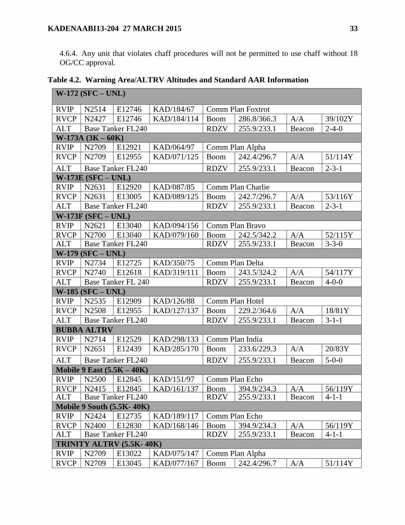
4.6. Chaff and Flare Use. .............................................................................................. 32
Table 4.2. Warning Area/ALTRV Altitudes and Standard AAR Information ....................... 33
Chapter 5—GROUND OPERATIONS 35
5.1. Controlled Movement Area (CMA). ...................................................................... 35
5.2. Lightning Procedures. ............................................................................................ 35
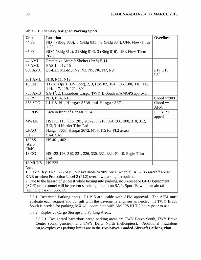
5.3. Aircraft Parking Plan. ............................................................................................ 35
Table 5.1. Primary Assigned Parking Spots ........................................................................... 36
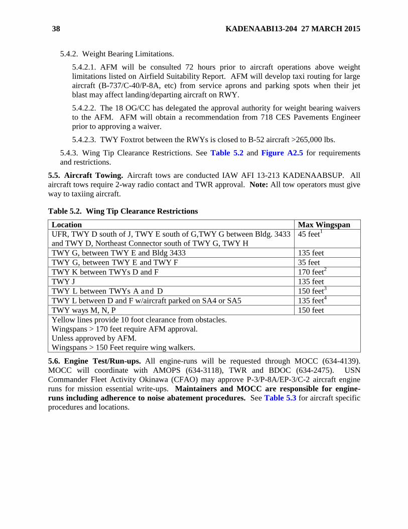
5.4. Aircraft Taxiing Requirements/Routes. ................................................................. 37
5.5. Aircraft Towing. .................................................................................................... 38
Table 5.2. Wing Tip Clearance Restrictions ........................................................................... 38
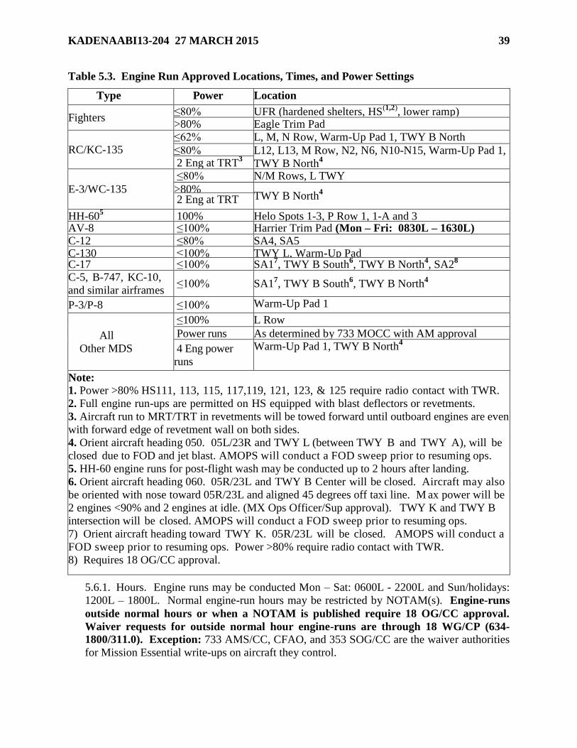
5.6. Engine Test/Run-ups. ............................................................................................. 38
Table 5.3. Engine Run Approved Locations, Times, and Power Settings .............................. 39
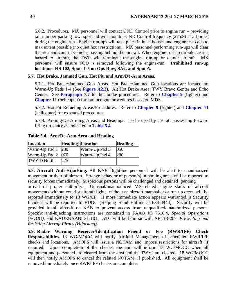
5.7. Hot Brake, Jammed Gun, Hot Pit, and Arm/De-Arm Areas. ................................. 40
Table 5.4. Arm/De-Arm Area and Heading ............................................................................ 40
5.8. Aircraft Anti-Hijacking. ......................................................................................... 40
5.9. Radar Warning Receiver/Identification Friend or Foe (RWR/IFF) Check
Responsibilities. ..................................................................................................... 40
Chapter 6—GENERAL FLYING OPERATIONS 41
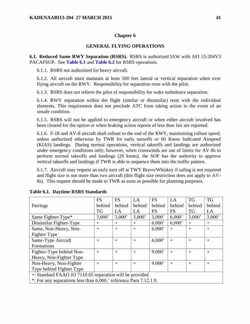
6.1. Reduced Same RWY Separation (RSRS). ............................................................. 41
Table 6.1. Daytime RSRS Standards ...................................................................................... 41
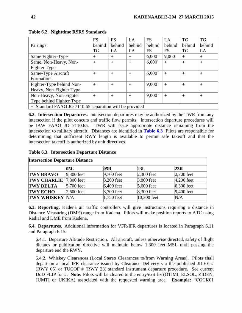
Table 6.2. Nighttime RSRS Standards .................................................................................... 42
6.2. Intersection Departures. ......................................................................................... 42
Table 6.3. Intersection Departure Distance ............................................................................. 42
6.3. Reporting. .............................................................................................................. 42
Page 5
KADENAABI13-204 27 MARCH 2015 5
6.4. Departures. ............................................................................................................. 42
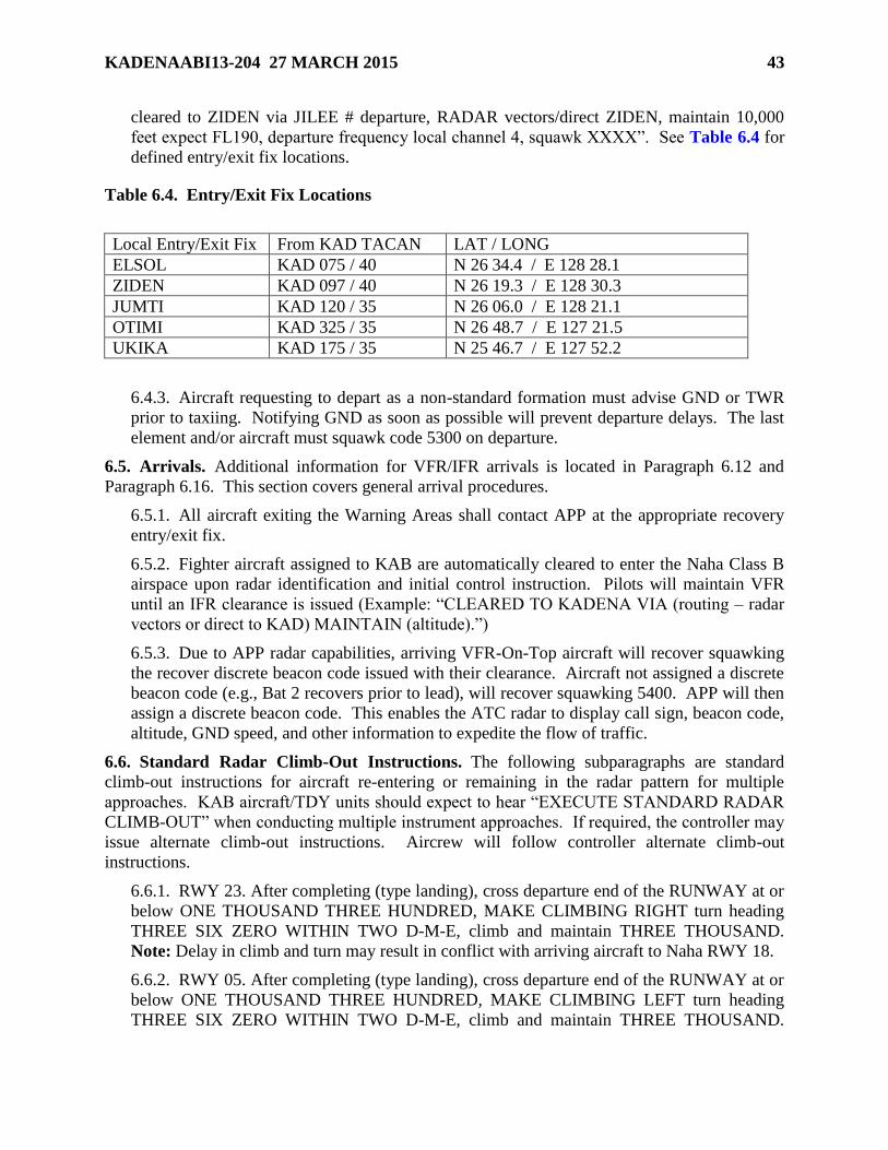
Table 6.4. Entry/Exit Fix Locations ........................................................................................ 43
6.5. Arrivals. ................................................................................................................. 43
6.6. Standard Radar Climb-Out Instructions. ................................................................ 43
6.7. Breakout/Go-Around/Missed Approach Procedures. ............................................ 44
6.8. Opposite Direction Take-Offs and Landings. ........................................................ 44
6.9. Lost Communications Procedures. ........................................................................ 45
6.10. General Procedures - Flying Operations VFR. ...................................................... 46
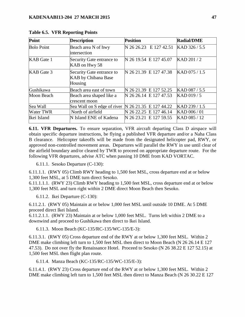
Table 6.5. VFR Reporting Points ............................................................................................ 47
6.11. VFR Departures. .................................................................................................... 47
6.12. VFR Arrivals. ......................................................................................................... 48
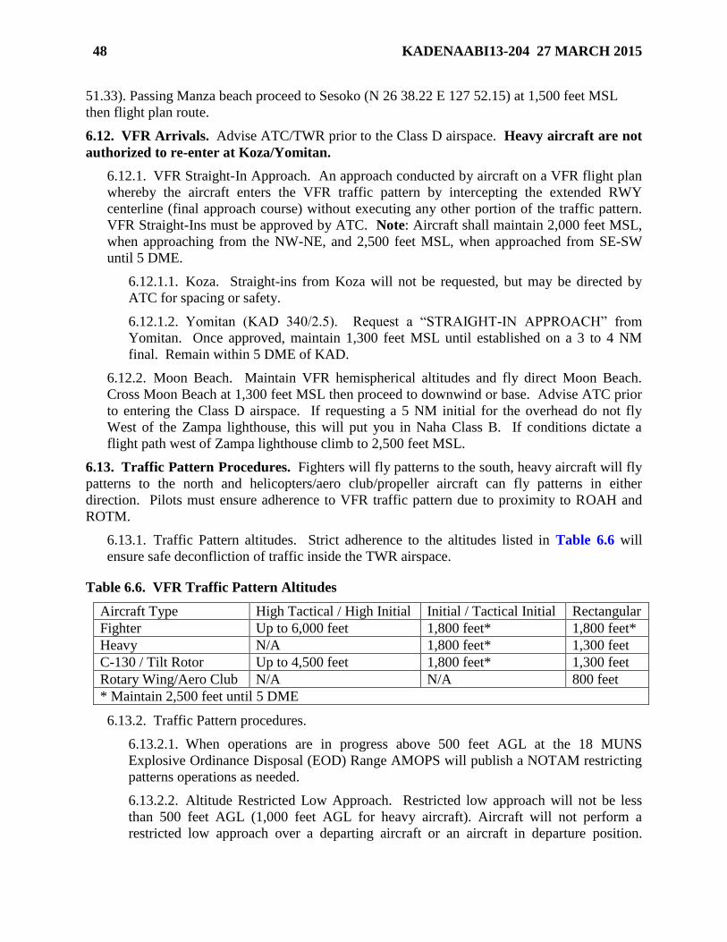
6.13. Traffic Pattern Procedures. .................................................................................... 48
Table 6.6. VFR Traffic Pattern Altitudes ................................................................................ 48
6.14. General Procedures – Flying Operations IFR. ....................................................... 49
6.15. IFR Departures. ...................................................................................................... 51
6.16. IFR Arrivals ........................................................................................................... 52
Chapter 7—EMERGENCY PROCEDURES 53
7.1. General. .................................................................................................................. 53
7.2. Operation of the Primary Crash Alarm System (PCAS) / Secondary Crash Net
(SCN). .................................................................................................................... 53
7.3. Emergency Response Procedures. ......................................................................... 55
7.4. Fuel Dumping. ....................................................................................................... 57
7.5. Emergency Aircraft Arresting System Procedures. ............................................... 58
7.6. Hot Brake Procedures. ........................................................................................... 58
7.7. Abandonment of Aircraft. ...................................................................................... 59
7.8. Personnel/Crash Locator Beacon Signal/Emergency Locator Transmitter
Response Procedures. ............................................................................................ 59
7.9. Overdue Aircraft AMOPS Procedures. .................................................................. 60
Table 7.1. Overdue Aircraft Checklist .................................................................................... 61
7.10. Wind Limitations on Control TWR. ...................................................................... 61
7.11. Evacuation of Airfield Operations (AO) Facilities. ............................................... 61
7.12. Alternate Facility Procedures. ................................................................................ 64
Page 6
6 KADENAABI13-204 27 MARCH 2015
Chapter 8—AIRFIELD MANAGEMENT/MISCELLANEOUS PROCEDURES 66
8.1. Airfield Operations Board (AOB). ........................................................................ 66
8.2. Notice to Airmen (NOTAM) Procedures. ............................................................. 67
8.3. Flight Information Publication (FLIP) Account Procedures. ................................. 68
8.4. Airfield Construction Procedures. ......................................................................... 68
8.5. Unlawful Seizure of Aircraft. ................................................................................ 72
8.6. Silent Launch Procedures (Steel Tiger). ................................................................ 72
8.7. Unmanned Aerial Systems (UAS) Operation Procedures. .................................... 75
Chapter 9—FIGHTER OPERATIONS 76
9.1. General Operations. ............................................................................................... 76
9.2. GND Operations. ................................................................................................... 76
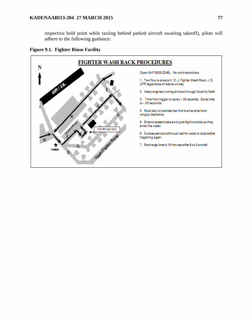
Figure 9.1. Fighter Rinse Facility ............................................................................................. 77
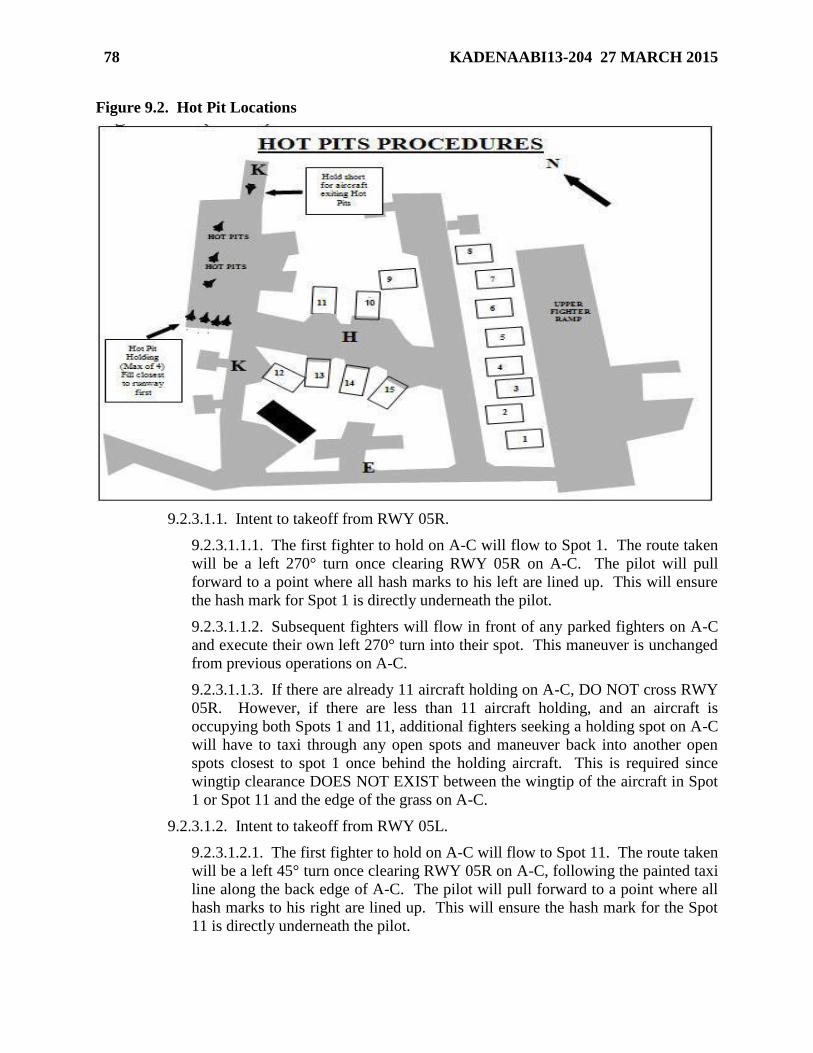
Figure 9.2. Hot Pit Locations ................................................................................................... 78
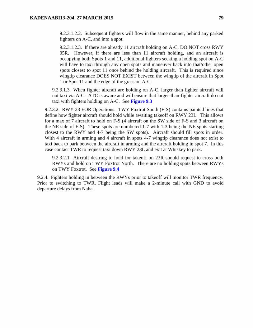
Figure 9.3. RWY 5R/L Hold Plan ............................................................................................ 80
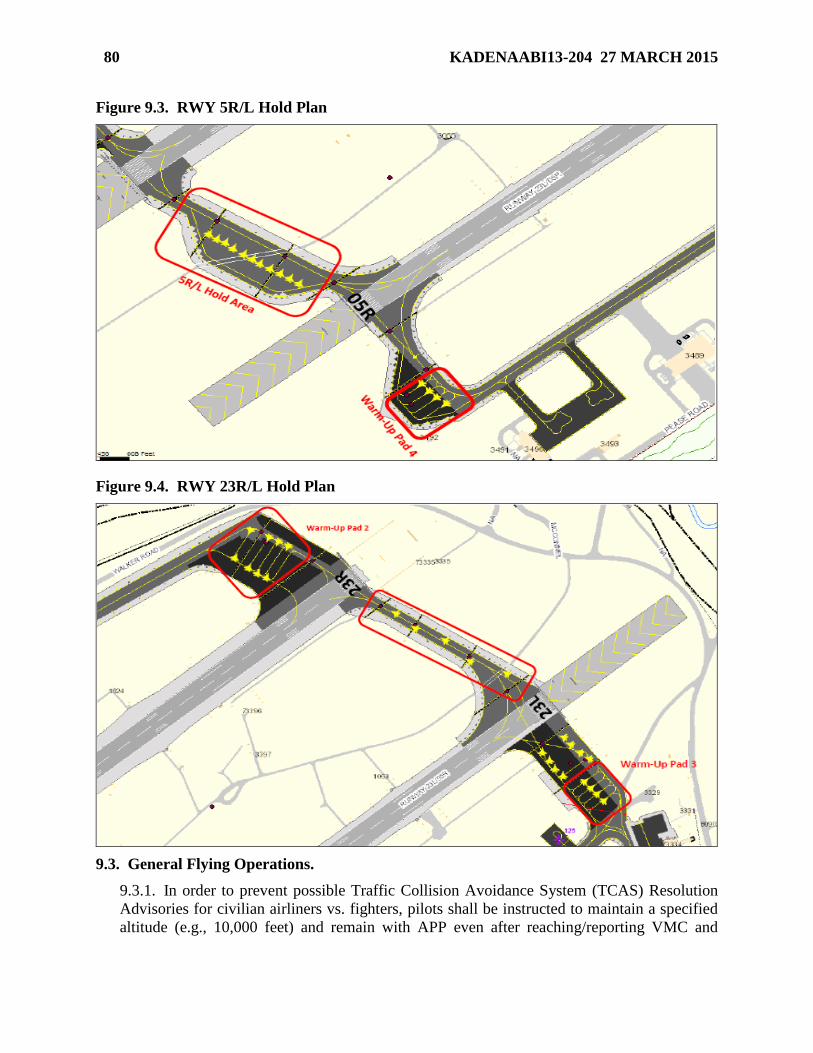
Figure 9.4. RWY 23R/L Hold Plan .......................................................................................... 80
9.3. General Flying Operations. .................................................................................... 80
9.4. Arrival. ................................................................................................................... 81
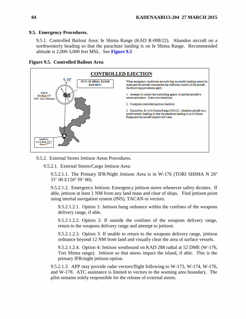
9.5. Emergency Procedures. .......................................................................................... 84
Figure 9.5. Controlled Bailout Area ......................................................................................... 84
9.6. AV-8 Operations at Kadena AB. ........................................................................... 86
Chapter 10—HEAVY/NON-FIGHTER OPERATIONS 88
10.1. General Operations. ............................................................................................... 88
10.2. GND Operations. ................................................................................................... 88
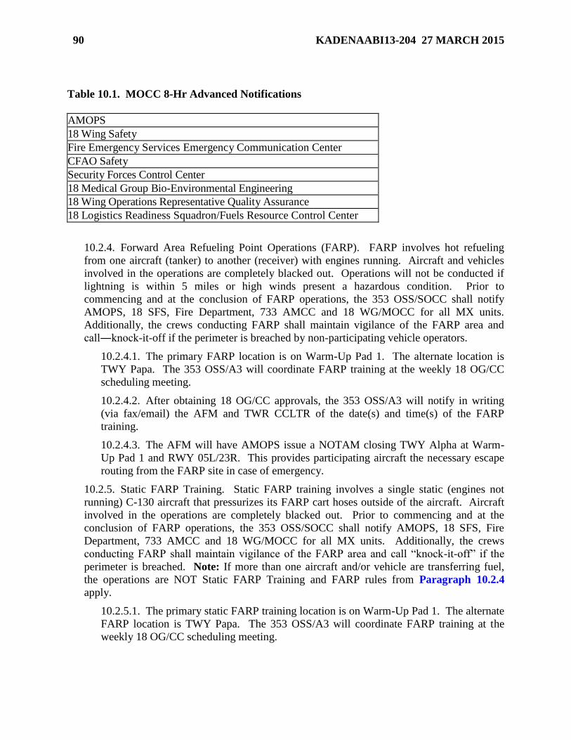
Table 10.1. MOCC 8-Hr Advanced Notifications .................................................................... 90
10.3. General Flying Operations. .................................................................................... 91
10.4. Arrival. ................................................................................................................... 93
10.5. Emergency Procedures. .......................................................................................... 93
10.6. 353 SOG Operations at Kadena AB. ..................................................................... 94
10.7. ALTRV AAR. ........................................................................................................ 98
Chapter 11—HELICOPTER OPERATIONS 100
11.1. General Operations. ............................................................................................... 100
11.2. GND Operations. ................................................................................................... 100
Page 7
KADENAABI13-204 27 MARCH 2015 7
11.3. General Flying Operations. .................................................................................... 100
11.4. Arrival Procedures. ................................................................................................ 100
11.5. Emergency Procedures. .......................................................................................... 101
11.6. 33d Rescue Squadron Standardized AAR Tracks. ................................................. 101
Table 11.1. AAR Tracks ........................................................................................................... 101
Chapter 12—CIVIL AIRCRAFT OPERATIONS 102
12.1. Civil Aircraft Operations. ...................................................................................... 102
12.2. Aero Club GND Operations. .................................................................................. 102
12.3. Aero Club General Flight Procedures. ................................................................... 102
12.4. Emergency Procedures. .......................................................................................... 104
12.5. Supervised Solo Operations. .................................................................................. 105
Attachment 1—GLOSSARY OF REFERENCES AND SUPPORTING INFORMATION 106
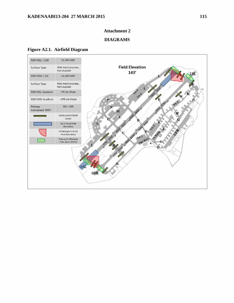
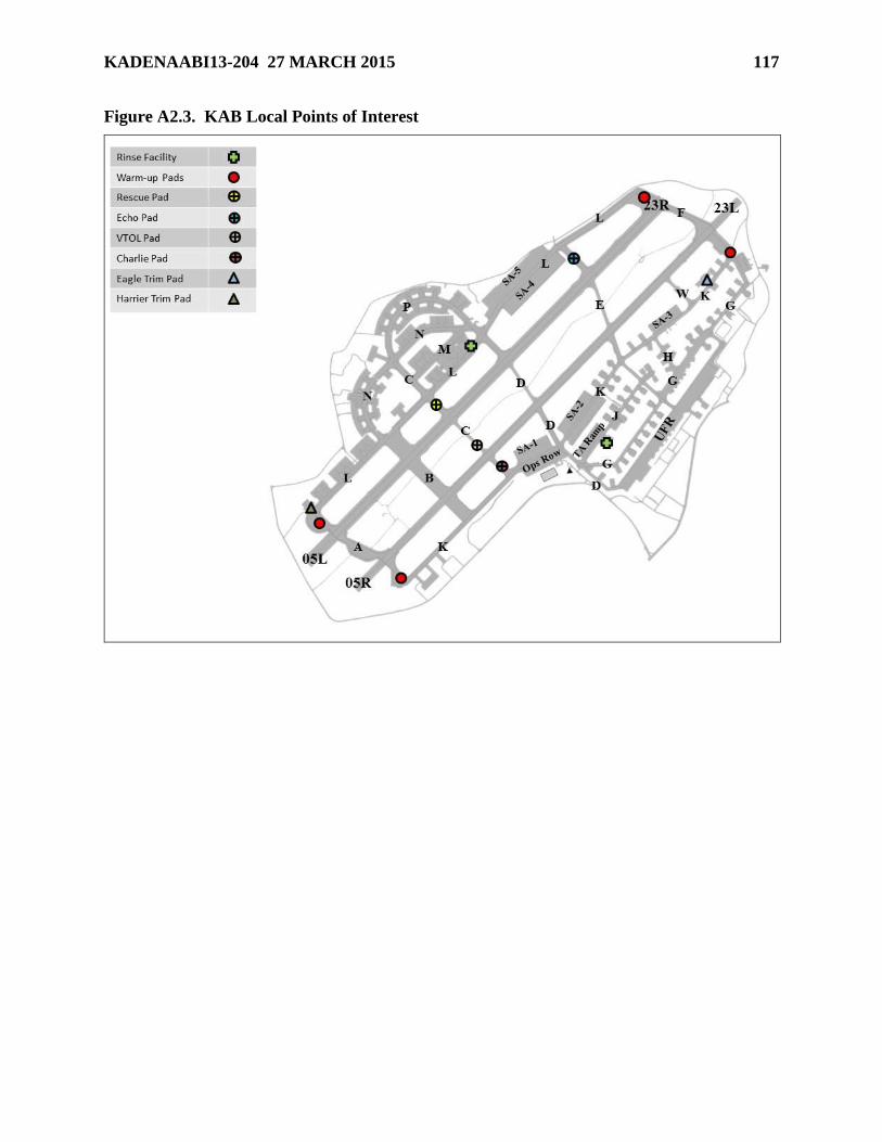
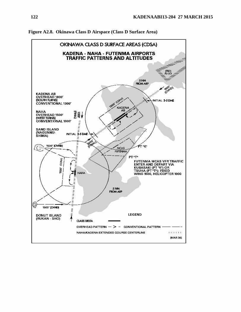
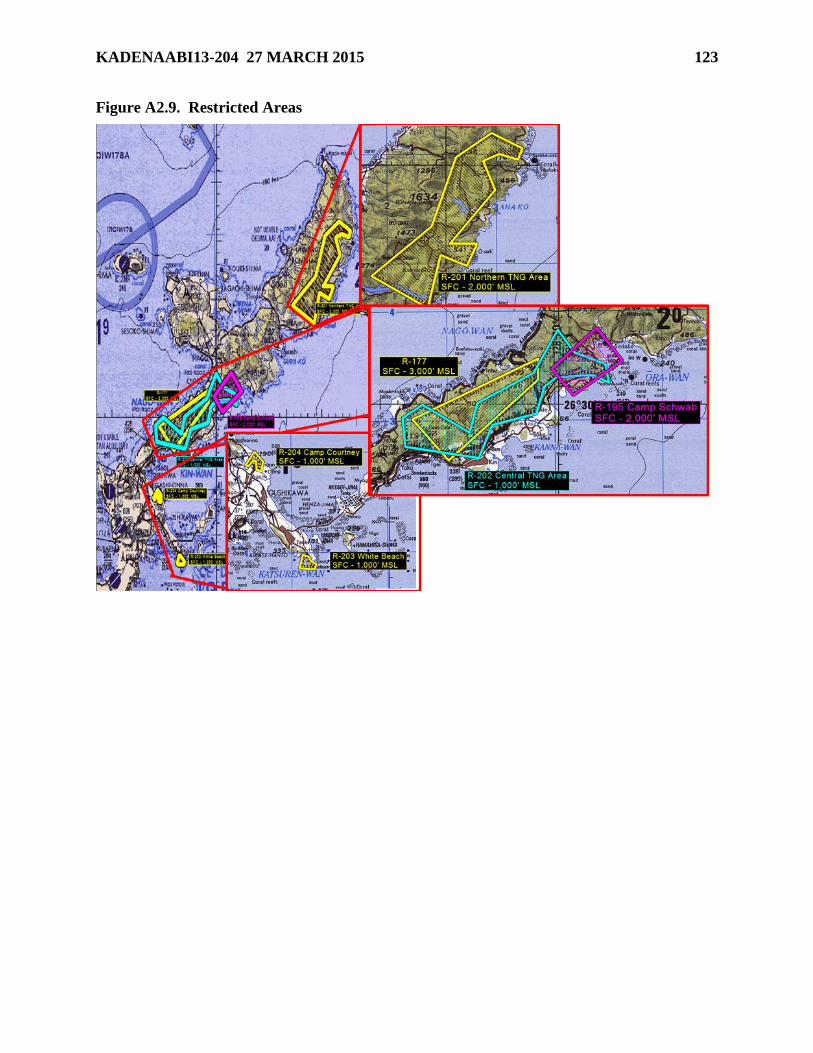
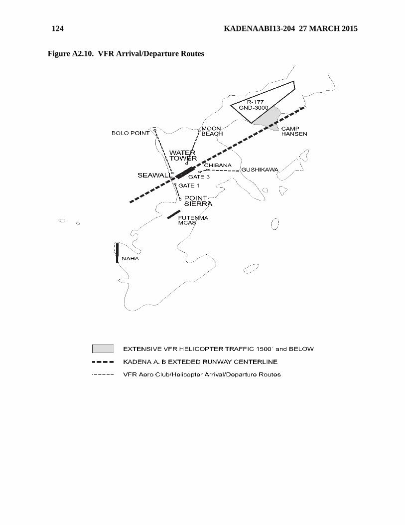
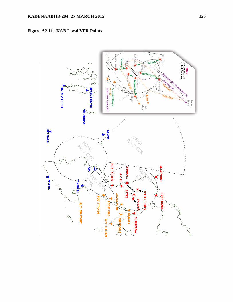
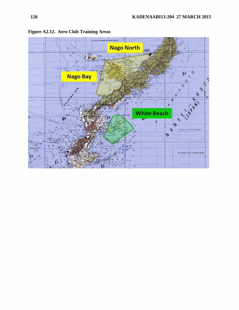
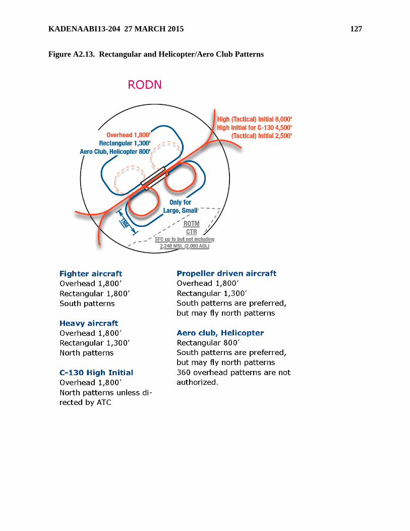
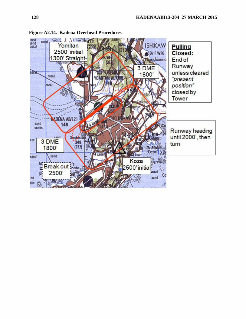
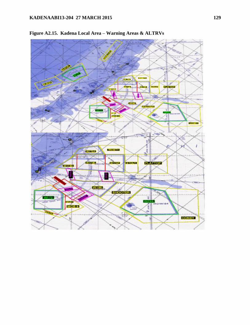
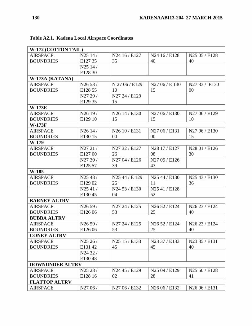
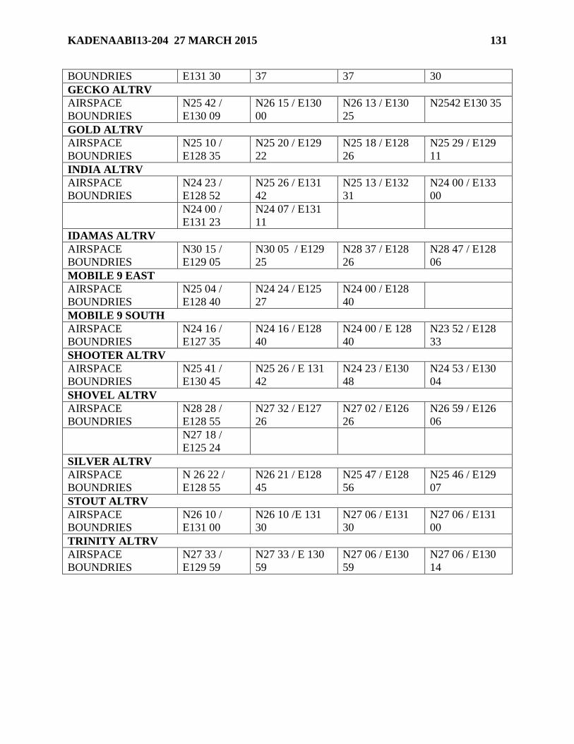
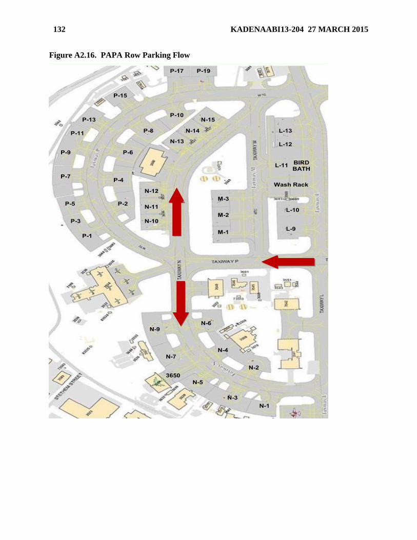
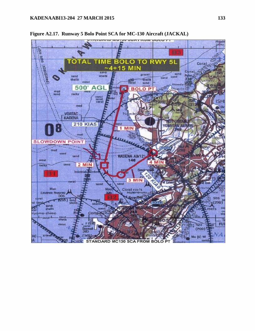
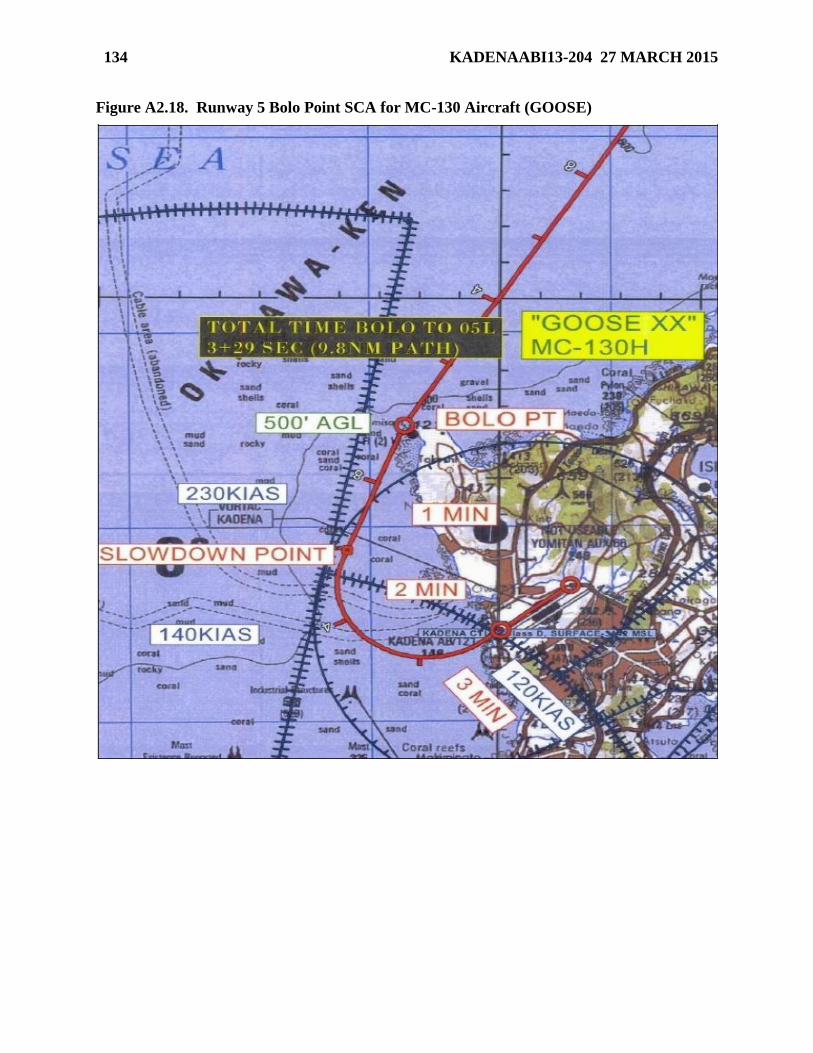
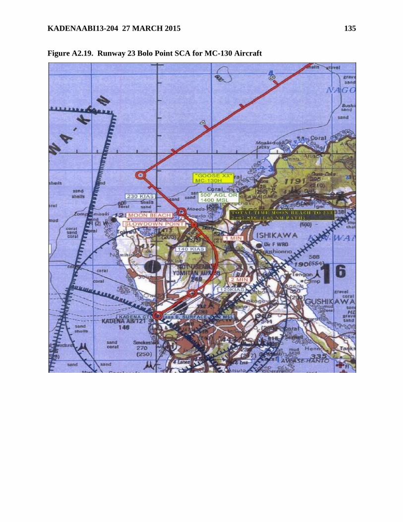
Attachment 2—DIAGRAMS 115
Page 8
8 KADENAABI13-204 27 MARCH 2015
Chapter 1
GENERAL INFORMATION
1.1. Scope. Procedures in this instruction are designed to promote safe and efficient airfield
operations and flying activities within Kadena Air Base (KAB) delegated airspace and to respect
host nation agreements. Commanders of assigned, tenant, and deployed units under the
operational control of the 18 WG will ensure their personnel comply with this publication.
1.2. Policy and Word Meaning. Each partner unit or assigned organization is responsible for
ensuring its personnel are familiar with this instruction.
1.2.1. Word Meanings. The following definitions apply within this instruction.
1.2.1.1. Shall, will, or must - indicate a mandatory procedure.
1.2.1.2. Should - indicates a recommended procedure.
1.2.1.3. May or need not - indicates an optional procedure.
1.2.2. General Prudential Rule. The procedures and policies set forth herein are not intended
to cover every contingency nor every rule of safety or good practice. All personnel are
expected to exercise prudent judgment in the performance of their mission.
1.3. Administration. The 18 OG/CC is the waiver authority for this regulation unless otherwise
annotated. The 18 OG/CC may issue waivers or immediate action changes to this regulation
when necessary for accomplishment of normal or special mission requirements. All procedural
changes affecting ATC must be forwarded to HQ PACAF/A3OF for review and approval before
implementation IAW AFI 13-204V3. Send suggested changes to 18 OSS/OSA
([email protected] ).
1.4. Published In-Flight Guide. 18th Operations Group Standardization and Evaluation (18
OG/OGV) shall retain current copies of all 18 OG flying squadron’s In-flight Guide and make
available via the 18 WG SharePoint.
Page 9
KADENAABI13-204 27 MARCH 2015 9
Chapter 2
AIRFIELD FACILITIES INFORMATION
2.1. Airfield Information: KAB is located at N26º21.20’, E127º46.03’, with a field elevation
of 143 feet Mean Sea Level (MSL).
2.2. ATC Facilities. Kadena Tower (TWR) is open 24 hrs per day, 7 days per week. Kadena
Ground Control Approach (GCA) is open 0800L - 2200L, Mon - Fri (except holidays). Kadena
Arrival Control (ARR) is open daily 0600L - 2200L, and as required for DoD missions.
2.2.1. Ground Controlled Approach. GCA Final Control is operated at the discretion of
MCAS Futenma, normally Mon - Fri, 0800L-2200L. Precision Approach Radars (PARs)
outside duty hours must be requested with 18 OSS/OSA. Note: Japanese airspace
regulations require that this facility be classified as Kadena GCA. However, per USMC
definitions, this facility meets the criteria of a Radar Final Control. The remainder of this
instruction will refer to this facility as a GCA.
2.2.2. Kadena Arrival. ARR provides arrival control and radar/instrument pattern control for
U.S. airfields in Okinawa. ARR also provides services required at landing zones/drop zones
and for aircraft operations aboard ships in and around the island of Okinawa. ARR is located
at the Naha Approach (APP) Control Facility at Naha Airport.
2.3. Runways (RWY). See Flight Information Publication (FLIP) for airfield diagram or
Figure A2.1 for detailed airfield depiction.
2.3.1. RWY 05L/23R: Dimensions. 12,101 feet by 300 feet (concrete/asphalt). RWY 23R
has 1,000 feet of non-load bearing overrun. RWY 05L has no overrun. RWY 05L has
grooved concrete from RWY threshold to 3,600 feet down the RWY. RWY 23R has
grooved concrete commencing at the RWY threshold extending 2,000 feet down the RWY.
The middle portion of RWY 05L/23R is grooved asphalt. RWY 05L/23R is the primary
instrument RWY.
2.3.2. RWY 05R/23L is 12,101 feet by 200 feet (concrete/asphalt). RWY 05R and RWY
23L have 1,000 feet grooved non-load bearing overruns. RWY 05R has 75 feet of grooved
pavement centered on the RWY centerline with un-grooved pavement immediately beyond
until 8,500 feet when the grooved surface is continuous across the RWY.
2.4. RWY Selection Procedures.
2.4.1. RWY 23 will be used for the calm wind RWY. TWR Watch Supervisor (WS) selects
RWY in use IAW Federal Aviation Administration Order (FAAO) Joint Order (JO) 7110.65,
Air Traffic Control.
2.4.2. When RWY change is anticipated, TWR will notify APP, ARR, GCA, Airfield
Management Operations (AMOPS), Futenma TWR, Fire Department, Barrier Maintenance
(MX), Weather (WX) and MX Operations Control Center (MOCC).
2.4.3. Upon RWY change, TWR will change the Instrument Landing System (ILS) to the
RWY in use and notify GCA. GCA will notify TWR, and ARR/APP when PAR equipment
is aligned with the proper RWY.
Page 10
10 KADENAABI13-204 27 MARCH 2015
2.5. Opening, Closing, and Suspending RWYs. Airfield Management Operations (AMOPS)
shall close/open/suspend RWY operations IAW AFI 13-204V3. TWR may suspend operations,
but only AMOPS may close/resume operations. A suspension announcement will be made on
TWR frequencies to include when RWY operations are expected to resume. Notice to Airmen
(NOTAM)(s) will be published for closures greater than 15 minutes. When closures are planned,
AMOPS will publish NOTAM(s) no earlier than 3 days in advance. AMOPS will advise local
agencies and 5 AF for closures greater than 72 hours. TWR will automatically suspend
operations for an emergency or any other unsafe condition within 100 feet of the RWY.
2.5.1. AMOPS will complete an airfield check and report the airfield status/RWY condition
prior to resuming operations.
2.6. RSC and/or RCR Values. AMOPS will conduct and report RWY Surface Condition
(RSC) on all active RWYs IAW AFI 13-204V3 and OSAA Operating Instruction (OI) 13-204,
Airfield Management Operations. RWY Condition Reading (RCR) is not reported at KAB.
2.6.1. 1 TWR will notify AMOPS as soon as practical upon observation of a condition that
may affect the landing area IAW OSAT OI 13-204, Air Traffic Control Operating
Procedures.
2.7. Taxiways (TWY). See Figure A2.1 for a detailed map of the RWY and TWYs.
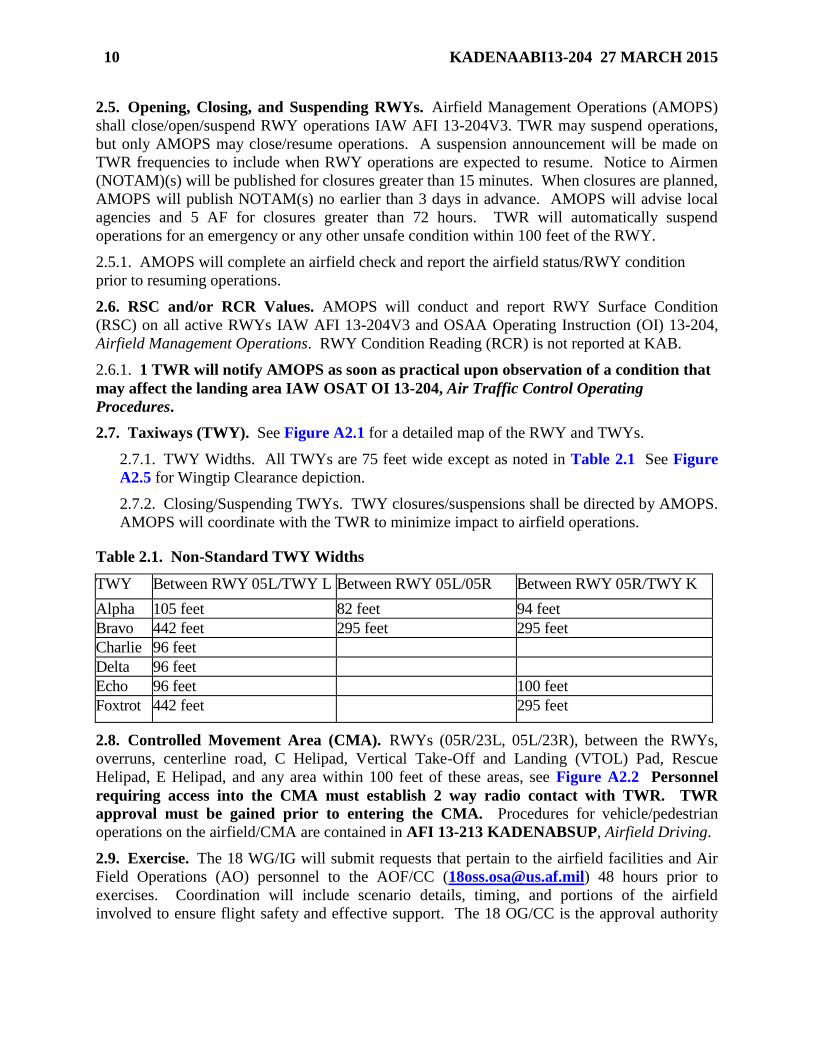
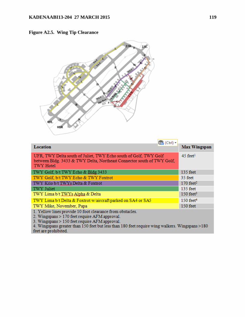
2.7.1. TWY Widths. All TWYs are 75 feet wide except as noted in Table 2.1 See Figure
A2.5 for Wingtip Clearance depiction.
2.7.2. Closing/Suspending TWYs. TWY closures/suspensions shall be directed by AMOPS.
AMOPS will coordinate with the TWR to minimize impact to airfield operations.
Table 2.1. Non-Standard TWY Widths
TWY Between RWY 05L/TWY L Between RWY 05L/05R Between RWY 05R/TWY K
Alpha 105 feet 82 feet 94 feet
Bravo 442 feet 295 feet 295 feet
Charlie 96 feet
Delta 96 feet
Echo 96 feet 100 feet
Foxtrot 442 feet 295 feet
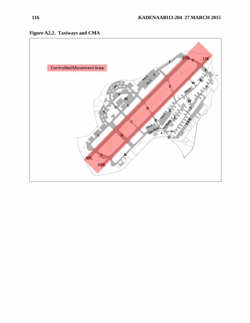
2.8. Controlled Movement Area (CMA). RWYs (05R/23L, 05L/23R), between the RWYs,
overruns, centerline road, C Helipad, Vertical Take-Off and Landing (VTOL) Pad, Rescue
Helipad, E Helipad, and any area within 100 feet of these areas, see Figure A2.2 Personnel
requiring access into the CMA must establish 2 way radio contact with TWR. TWR
approval must be gained prior to entering the CMA. Procedures for vehicle/pedestrian
operations on the airfield/CMA are contained in AFI 13-213 KADENABSUP, Airfield Driving.
2.9. Exercise. The 18 WG/IG will submit requests that pertain to the airfield facilities and Air
Field Operations (AO) personnel to the AOF/CC ([email protected] ) 48 hours prior to
exercises. Coordination will include scenario details, timing, and portions of the airfield
involved to ensure flight safety and effective support. The 18 OG/CC is the approval authority
Page 11
KADENAABI13-204 27 MARCH 2015 11
for simulated TWY/RWY closures. WS/SC shall interrupt exercise facility participation during
an emergency or safety issue.
2.10. Airfield Visual Blind Spots.
2.10.1. Primary TWR. TWYs November, Papa, and Kilo between TWYs Echo and Foxtrot,
TWY Hotel, Upper Fighter Ramp (UFR) spots 1-50, CME parking apron, and the
intersection of TWYs Juliet and Delta cannot be seen from the TWR. TWR cannot provide
positive control for aircraft operating in these areas.
2.10.2. Alternate TWR. The UFR, TWY Golf East of TWY Echo, TWY Whiskey south of
the Navy Ramp, TWY Hotel, TWY Lima West of parking spot L-8 to TWY Alpha, TWY
November West of TWY Charlie, TWY Papa West of parking spot P-11 and TWY Charlie
between TWY Lima and Mike cannot be seen from the Alternate TWR. Parts of TWY Juliet
are not visible when aircraft are parked on SA2 or spots 102-114.
2.11. Closed Portions of Airfield. Hardstand (HS) 116, 118 and 333 are permanently closed.
2.12. Restricted/Classified Areas on the Airfield.
2.12.1. Controlled Areas.
2.12.1.1. The airfield is a controlled area as defined in Kadena Air Base Instruction
(KADENAABI) 31-101, The Kadena AB Integrated Defense (FOUO), and AFI 31-101,
Integrated Defense (FOUO). Entry to the airfield is Official Business Only and all
personnel on the airfield must have identifying credentials.
2.12.1.2. Custodians of non-priority aircraft parking and MX areas will challenge
unauthorized/suspicious individuals within the controlled area. Individuals must be
positively identified and must be conducting official duties. Unauthorized individuals
will be immediately reported to Base Defense Operations Center (BDOC) (Routine calls:
634-2475/2476, Emergency: Helping Hand Hotline at 634-4444).
2.12.1.3. Contractors will possess either 5 AF Form 98EJ, Standard Pass (Storage
Safeguard) or 5 AF Form 98A EJ, Temporary Pass (Storage Safeguard) over-stamped
CONTRACTOR. A list of contractors performing duties on the airfield will be provided
to BDOC, MOCC, and AMOPS for verification purposes. All contractors operating a
POV on the airfield must have proper escort for access to restricted areas and must
comply with requirements in AFI 13-213 KADENAABSUP.
2.12.2. Restricted Areas.
2.12.2.1. KADENAABI 31-101-O, The Kadena AB Integrated Defense (FOUO),
outlines restricted area numbers, physical locations, descriptions of the areas, priority,
organizations who control designated areas and escort and control procedures.
2.12.2.2. All personnel within restricted areas must be vigilant for unauthorized intruders
or any suspicious acts. Challenge any person without a badge with the appropriate
restricted area number. To initiate implementation of a security incident, notify security
forces immediately after the individual is in the final challenge position.
2.12.2.3. Report observed security violations to BDOC (634-4444).
Page 12
12 KADENAABI13-204 27 MARCH 2015
2.12.2.4. Crossing the restricted area boundary, red rope, or painted red line at locations
other than designated entry points is unauthorized. This act violates security procedures
and will initiate a Security Incident.
2.12.3. Free Zone.
2.12.3.1. Free zones (no protection level resources) are areas established within restricted
areas when construction projects and similar activities make it inappropriate or
impractical to apply normal circulation controls.
2.12.3.2. Requests for the establishment of a Free Zone will be submitted to the
Integrated Defense Council IAW KADENAABI 31-101.
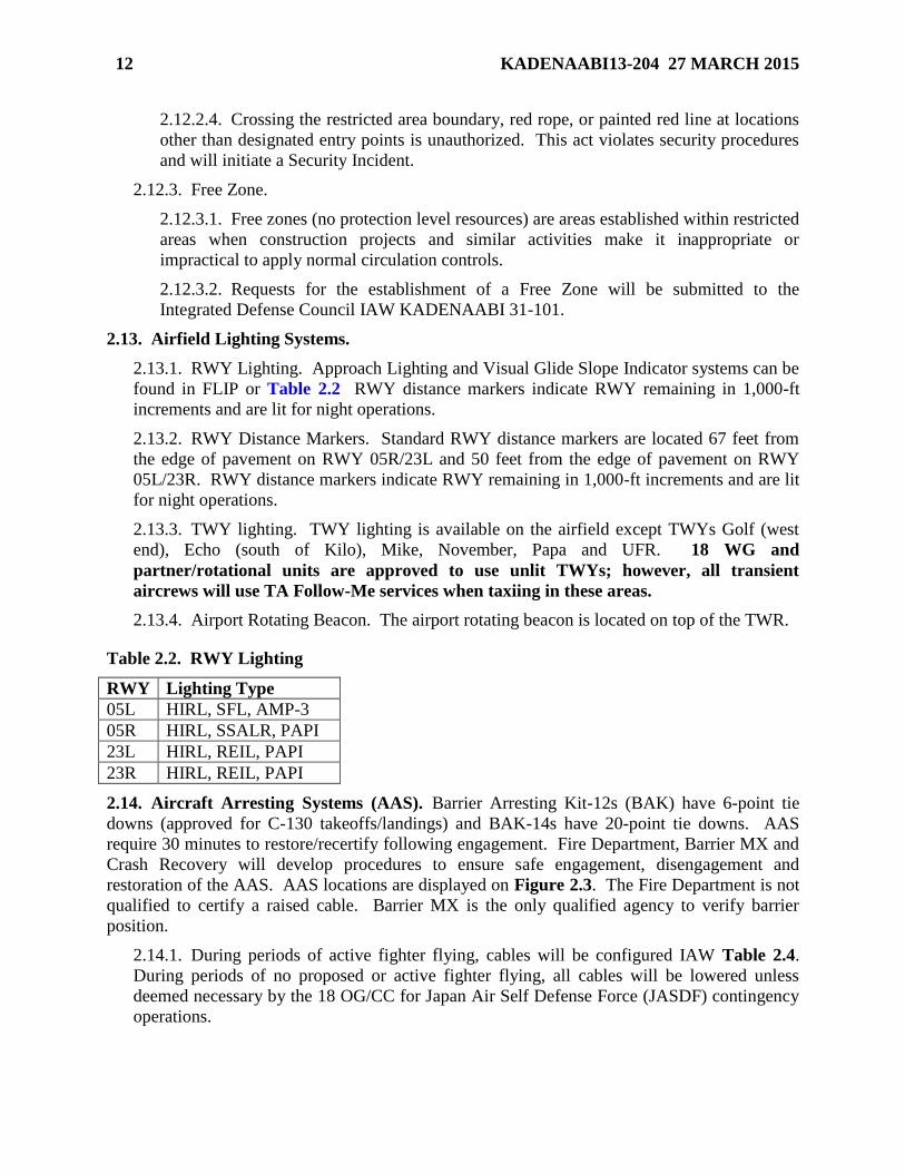
2.13. Airfield Lighting Systems.
2.13.1. RWY Lighting. Approach Lighting and Visual Glide Slope Indicator systems can be
found in FLIP or Table 2.2 RWY distance markers indicate RWY remaining in 1,000-ft
increments and are lit for night operations.
2.13.2. RWY Distance Markers. Standard RWY distance markers are located 67 feet from
the edge of pavement on RWY 05R/23L and 50 feet from the edge of pavement on RWY
05L/23R. RWY distance markers indicate RWY remaining in 1,000-ft increments and are lit
for night operations.
2.13.3. TWY lighting. TWY lighting is available on the airfield except TWYs Golf (west
end), Echo (south of Kilo), Mike, November, Papa and UFR. 18 WG and
partner/rotational units are approved to use unlit TWYs; however, all transient
aircrews will use TA Follow-Me services when taxiing in these areas.
2.13.4. Airport Rotating Beacon. The airport rotating beacon is located on top of the TWR.
Table 2.2. RWY Lighting
RWY Lighting Type
05L HIRL, SFL, AMP-3
05R HIRL, SSALR, PAPI
23L HIRL, REIL, PAPI
23R HIRL, REIL, PAPI
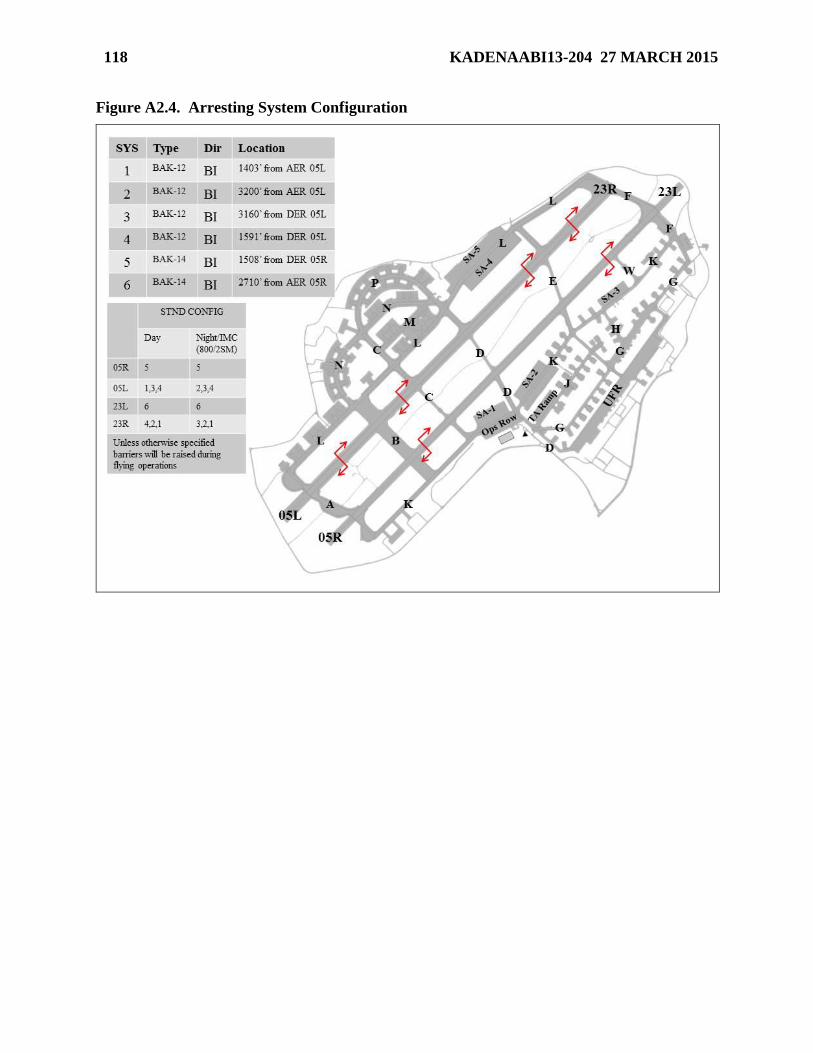
2.14. Aircraft Arresting Systems (AAS). Barrier Arresting Kit-12s (BAK) have 6-point tie
downs (approved for C-130 takeoffs/landings) and BAK-14s have 20-point tie downs. AAS
require 30 minutes to restore/recertify following engagement. Fire Department, Barrier MX and
Crash Recovery will develop procedures to ensure safe engagement, disengagement and
restoration of the AAS. AAS locations are displayed on Figure 2.3. The Fire Department is not
qualified to certify a raised cable. Barrier MX is the only qualified agency to verify barrier
position.
2.14.1. During periods of active fighter flying, cables will be configured IAW Table 2.4.
During periods of no proposed or active fighter flying, all cables will be lowered unless
deemed necessary by the 18 OG/CC for Japan Air Self Defense Force (JASDF) contingency
operations.
Page 13
KADENAABI13-204 27 MARCH 2015 13
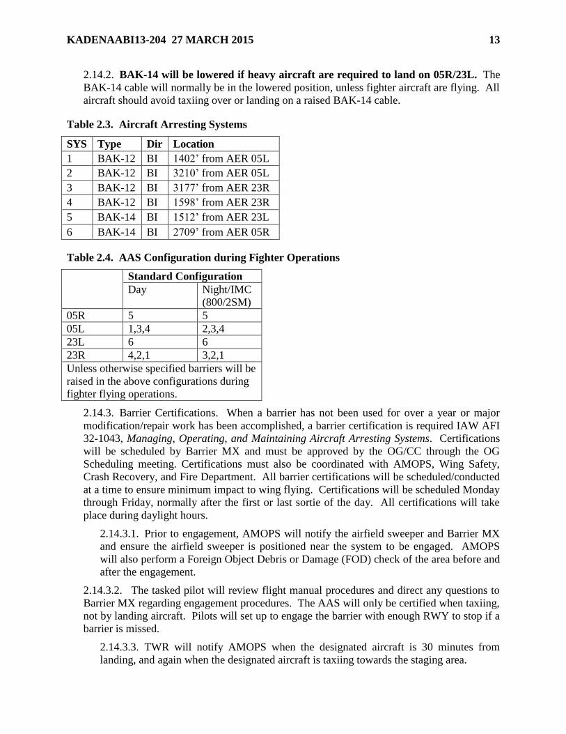
2.14.2. BAK-14 will be lowered if heavy aircraft are required to land on 05R/23L. The
BAK-14 cable will normally be in the lowered position, unless fighter aircraft are flying. All
aircraft should avoid taxiing over or landing on a raised BAK-14 cable.
Table 2.3. Aircraft Arresting Systems
SYS Type Dir Location
1 BAK-12 BI 1402’ from AER 05L
2 BAK-12 BI 3210’ from AER 05L
3 BAK-12 BI 3177’ from AER 23R
4 BAK-12 BI 1598’ from AER 23R
5 BAK-14 BI 1512’ from AER 23L
6 BAK-14 BI 2709’ from AER 05R
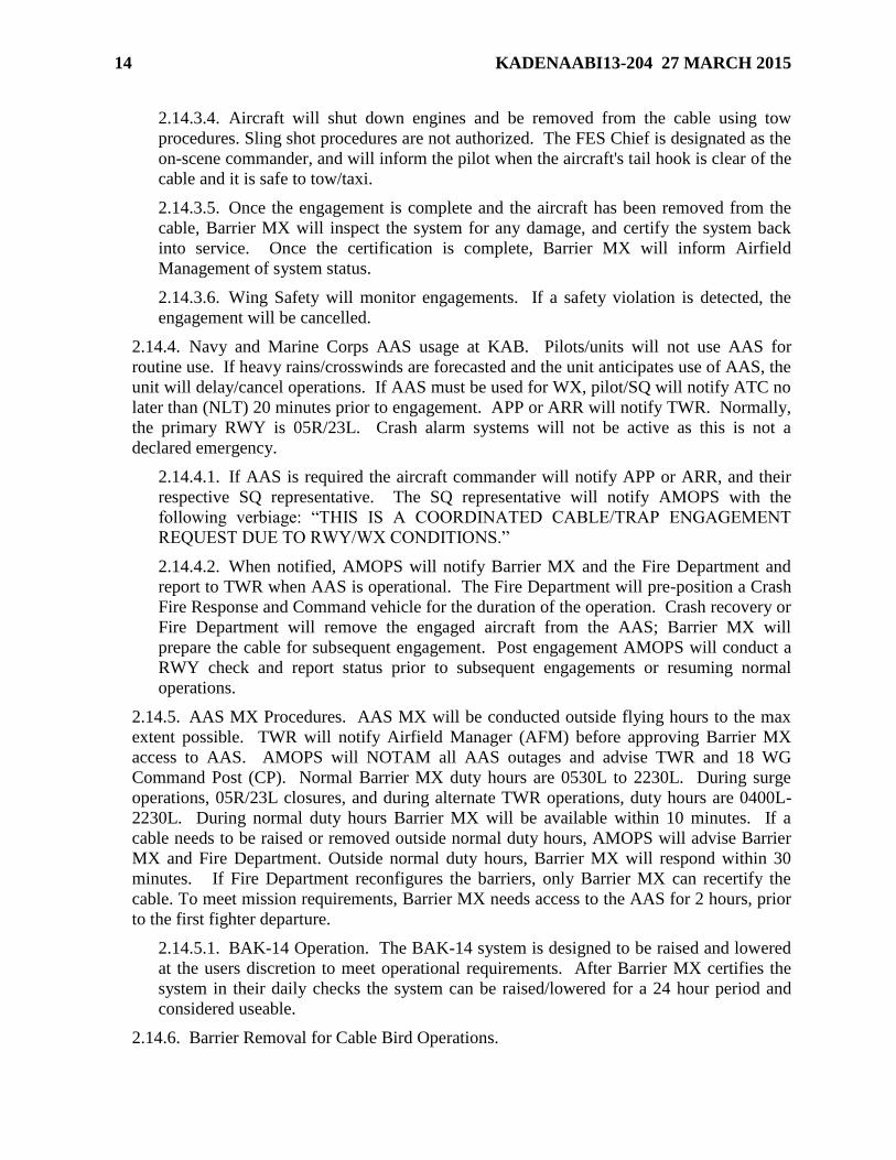
Table 2.4. AAS Configuration during Fighter Operations
Standard Configuration
Day Night/IMC
(800/2SM)
05R 5 5
05L 1,3,4 2,3,4
23L 6 6
23R 4,2,1 3,2,1
Unless otherwise specified barriers will be
raised in the above configurations during
fighter flying operations.
2.14.3. Barrier Certifications. When a barrier has not been used for over a year or major
modification/repair work has been accomplished, a barrier certification is required IAW AFI
32-1043, Managing, Operating, and Maintaining Aircraft Arresting Systems. Certifications
will be scheduled by Barrier MX and must be approved by the OG/CC through the OG
Scheduling meeting. Certifications must also be coordinated with AMOPS, Wing Safety,
Crash Recovery, and Fire Department. All barrier certifications will be scheduled/conducted
at a time to ensure minimum impact to wing flying. Certifications will be scheduled Monday
through Friday, normally after the first or last sortie of the day. All certifications will take
place during daylight hours.
2.14.3.1. Prior to engagement, AMOPS will notify the airfield sweeper and Barrier MX
and ensure the airfield sweeper is positioned near the system to be engaged. AMOPS
will also perform a Foreign Object Debris or Damage (FOD) check of the area before and
after the engagement.
2.14.3.2. The tasked pilot will review flight manual procedures and direct any questions to
Barrier MX regarding engagement procedures. The AAS will only be certified when taxiing,
not by landing aircraft. Pilots will set up to engage the barrier with enough RWY to stop if a
barrier is missed.
2.14.3.3. TWR will notify AMOPS when the designated aircraft is 30 minutes from
landing, and again when the designated aircraft is taxiing towards the staging area.
Page 14
14 KADENAABI13-204 27 MARCH 2015
2.14.3.4. Aircraft will shut down engines and be removed from the cable using tow
procedures. Sling shot procedures are not authorized. The FES Chief is designated as the
on-scene commander, and will inform the pilot when the aircraft's tail hook is clear of the
cable and it is safe to tow/taxi.
2.14.3.5. Once the engagement is complete and the aircraft has been removed from the
cable, Barrier MX will inspect the system for any damage, and certify the system back
into service. Once the certification is complete, Barrier MX will inform Airfield
Management of system status.
2.14.3.6. Wing Safety will monitor engagements. If a safety violation is detected, the
engagement will be cancelled.
2.14.4. Navy and Marine Corps AAS usage at KAB. Pilots/units will not use AAS for
routine use. If heavy rains/crosswinds are forecasted and the unit anticipates use of AAS, the
unit will delay/cancel operations. If AAS must be used for WX, pilot/SQ will notify ATC no
later than (NLT) 20 minutes prior to engagement. APP or ARR will notify TWR. Normally,
the primary RWY is 05R/23L. Crash alarm systems will not be active as this is not a
declared emergency.
2.14.4.1. If AAS is required the aircraft commander will notify APP or ARR, and their
respective SQ representative. The SQ representative will notify AMOPS with the
following verbiage: “THIS IS A COORDINATED CABLE/TRAP ENGAGEMENT
REQUEST DUE TO RWY/WX CONDITIONS.”
2.14.4.2. When notified, AMOPS will notify Barrier MX and the Fire Department and
report to TWR when AAS is operational. The Fire Department will pre-position a Crash
Fire Response and Command vehicle for the duration of the operation. Crash recovery or
Fire Department will remove the engaged aircraft from the AAS; Barrier MX will
prepare the cable for subsequent engagement. Post engagement AMOPS will conduct a
RWY check and report status prior to subsequent engagements or resuming normal
operations.
2.14.5. AAS MX Procedures. AAS MX will be conducted outside flying hours to the max
extent possible. TWR will notify Airfield Manager (AFM) before approving Barrier MX
access to AAS. AMOPS will NOTAM all AAS outages and advise TWR and 18 WG
Command Post (CP). Normal Barrier MX duty hours are 0530L to 2230L. During surge
operations, 05R/23L closures, and during alternate TWR operations, duty hours are 0400L-
2230L. During normal duty hours Barrier MX will be available within 10 minutes. If a
cable needs to be raised or removed outside normal duty hours, AMOPS will advise Barrier
MX and Fire Department. Outside normal duty hours, Barrier MX will respond within 30
minutes. If Fire Department reconfigures the barriers, only Barrier MX can recertify the
cable. To meet mission requirements, Barrier MX needs access to the AAS for 2 hours, prior
to the first fighter departure.
2.14.5.1. BAK-14 Operation. The BAK-14 system is designed to be raised and lowered
at the users discretion to meet operational requirements. After Barrier MX certifies the
system in their daily checks the system can be raised/lowered for a 24 hour period and
considered useable.
2.14.6. Barrier Removal for Cable Bird Operations.
Page 15
KADENAABI13-204 27 MARCH 2015 15
2.14.6.1. RWY 05R/23L is the primary RWY for Cable Bird operations. Annotate
“Cable Bird” in the Remarks section of the DD Form 1801, International Flight Plan,
DoD.
2.14.6.2. If RWY 05R/23L is not available, TWR will ensure barriers are removed from
RWY 05L/23R prior to Cable Bird missions, unless other configurations are approved by
the pilot. If applicable, TWR clearance for takeoff/landing will include the phrase
“BARRIERS ARE DOWN” or “BARRIERS INDICATE DOWN.” Barriers will not be
removed until Cable Bird plans a full stop. Cable Bird requests for touch-and-go training
will not be approved unless requested at weekly scheduling meeting and approval is
obtained from 18 OSS/OSA.
2.15. ATC and Landing Systems (ATCALS). See FLIP for preventive MX schedules.
2.15.1. GND Navigational Aid (NAVAID) checkpoints are located on all warm-up pads.
Very High Frequency Omni-directional Radio-Range (VOR) checkpoint is not available on
Warm-Up Pad 4.
2.15.2. Airport Surveillance Radar (ASR). The ASR antenna is located at Naha Airport.
APP and ARR utilize the ASR to provide radar approach, departure, and arrival services for
all aircraft operations within the Naha Positive Control Area (PCA), approach control, and
arrival control delegated airspaces.
2.15.3. Digital Airport Surveillance Radar (DASR). The DASR antenna is located on KAB.
Kadena TWR/GCA and Futenma TWR/GCA utilize the DASR to provide TWR and GCA
services.
2.15.4. Precision Approach Radar (PAR). The PAR is located between the RWYs and
provides precision radar approach to all RWYs. KAB has dual PAR capability. The PAR is
operated by the USMC in accordance with established memorandums of agreement. USAF
aircrews may request PAR approaches or monitored ILS approaches during emergencies,
aircraft equipment malfunctions, during Instrument Meteorological Conditions (IMC) or for
training.
2.15.5. Civil Use of Military ATCALS. Civil aircraft may be issued radar vectors and
permitted to use USAF NAVAID for practice and multiple low approaches at KAB as long
as such approaches do not delay mission-essential traffic. ATC supervisory personnel make
the determination to permit or deny these operations based on current and projected traffic
conditions. Civil aircraft must have a landing permit or approval from the installation
commander to land.
2.15.6. Auxiliary Power Requirements.
2.15.6.1. The primary back-up power system for the TWR and GCA is the air
commercial power plant, which has an auto-start capability. The back-up systems for the
air commercial power plant are TWR and GCA individual facility generators (building
3418 and 3413), which also have auto-start capability on a 5 second delay behind the air
commercial power plant. In the event both air commercial power plant and the individual
facility generators fail to auto-start, controllers, if trained, are authorized to manually start
the units. Under such circumstances, the WS or Senior Controller (SC) shall:
2.15.6.1.1. Follow the appropriate facility checklist.
Page 16
16 KADENAABI13-204 27 MARCH 2015
2.15.6.1.2. Ensure the generators are started.
2.15.6.1.3. Under normal conditions following a commercial power outage, air
commercial power will auto-start with a 5 second delay and feed 100% of the load to
both the TWR and GCA. In the event air commercial power fails to auto-start,
individual facility generators in buildings 3418 and 3413 assume the load within 10 to
15 seconds. The facility generator in the GCA feeds only the technical load in the
IFR room (scopes and Enhanced Terminal Voice Switch (ETVS)); the TWR facility
generator feeds the elevator and technical load. Once air commercial power is online
the building generators’ transfer system times out and switches the load to the air
commercial power plant. The building generators will then automatically shut down.
During all transfer processes the GCA Uninterrupted Power Supply (UPS) will
assume load on initial outage and act as a filter to incoming generator power. When
commercial power is restored, air commercial power plant generator will
automatically begin re-transfer and shut-down operations. Once the transfer systems
have timed out the generator will automatically shut-down. The air commercial
power plant is normally manned. However, during severe WX/tropical cyclone
conditions of readiness (TCCOR) conditions, power plant production personnel are
on standby at the 18 CEG/UCC, building 1461, 24-hours a day.
2.15.6.2. 18 CES/CEO shall ensure:
2.15.6.2.1. Power production personnel complete required preventative MX
inspections (PMIs) to achieve a 100% reliability rate. PMIs include checking fluid
level and if power transfer control panel are properly set.
2.15.6.2.2. During periods of extended operations on auxiliary power, if manning and
mission priorities provide for, check and notify facility managers of generator fuel
status. However, facility managers must be proactive and ensure their generator(s)
are checked every 2 hours.
2.15.6.2.3. The auto-start or auto-transfer system is tested IAW AFI 13-204V3,
Airfield Operations Programs and Procedures, and AFI 32-1062, Electrical Systems,
Power Plants and Generators. Use procedures that duplicate conditions during a
nonscheduled power outage (e.g., kill commercial power to auto transfer panel).
2.15.6.2.4. Power production personnel coordinate with 18 OSS/OSAM and the
GCA prior to testing or transferring power at an Airfield System and/or with the
affected ATC facility prior to transferring power at transmitter or receiver site.
2.15.6.2.5. Qualified personnel will respond to emergency ATCALS back-up
generator failure within 20 minutes during normal duty hours (0730L-1630L). After
hours (1630L-0730L, weekends, and holidays), response time will be as soon as
possible but not later than 1 hour.
2.15.6.2.6. Generator certification training is provided to 18 OSS/OSA as needed (no
less than annually).
2.15.6.3. 18 OSS/OSA shall:
2.15.6.3.1. Ensure the GCA/TWR WS notifies other ATC agencies prior to ATCALS
transferring to back-up power. This will allow 18 CES personnel to check the
Page 17
KADENAABI13-204 27 MARCH 2015 17
building generators’ auto-start and load assumption feature without impacting flying
operations.
2.15.6.3.2. Ensure personnel are trained by 18 CES/CEO as needed (no less than
annually) and can provide documentation of training.
2.15.6.4. 18 OSS Operational Support ATCALS MX (OSAM) shall ensure:
2.15.6.4.1. On-site MX technicians are available for any generator test affecting an
ATCALS component.
2.15.6.4.2. The 18 OSS/OSAM is the central coordination point between ATC and
18 CES.
2.15.6.4.3. Under extended auxiliary power operations (continuous generator
operations longer than one hour), facility managers, via their certified generator
personnel, will visually check the generator(s) for signs of concern (e.g., fuel, coolant
or oil leaks), document the AF Form 487, Emergency Generator Operation Log
(Inspection Testing), of the appropriate reading/data per their training, and check and
schedule fuel deliveries through base fuels.
2.16. Protection of Precision Approach Critical Areas. Instrument hold lines provide
protection for localizer and glide slope critical areas and the precision obstacle free zone (POFZ).
2.16.1. ILS.
2.16.1.1. Glideslope and Localizer Critical Areas. Procedures IAW AFI 13-204V3 (See
Figure A2.1). Exception: When the ceiling is below 800 feet and/or the visibility is less
than 2 miles, TWR shall not permit any type of vehicle or aircraft to proceed beyond the
instrument hold line when an aircraft is conducting an ILS approach and is inside the
final approach fix.
2.16.1.2. GND will restrict vehicles from using centerline road between TWYs Alpha
and Bravo (RWY 05), or TWYs Echo and Foxtrot (RWY 23) when the ceiling is less
than 800 feet and/or visibility is less than 2 miles and an aircraft executing an ILS is at or
inside the final approach fix.
2.16.2. POFZ. Procedures IAW FAAO JO 7110.65.
2.16.3. Instrument Hold Lines. Critical areas are marked by instrument hold lines located on
TWYs Alpha, Bravo, Echo and Foxtrot on the north and south sides of RWYs 05L/23R and
on TWYs Alpha, Bravo, Whiskey and Foxtrot on the north and south sides of RWY
05R/23L.
2.17. WX Dissemination and Coordination Procedures. 18 OSS/OSW is responsible for
taking, recording, and disseminating surface WX observations. This service is provided 24 hours
a day, 7 days a week. Procedures are outlined in the 18 WG PLAN 15-1, Weather Support Plan
(WSP).
2.17.1. ATC shall disseminate significant WX condition changes (e.g., hazardous/severe
WX, lightning, etc.) IAW FAAO JO 7110.65 and the 18 WG PLAN 15-1, Annex 5 to Annex
H, Tab E, para 2.c.1. The primary method for disseminating WX information to command
and control agencies, and to ground operation centers, is via the Joint Environmental Toolkit
(JET).
Page 18
18 KADENAABI13-204 27 MARCH 2015
2.17.2. 18 OSS/OSW will disseminate WX information by phone to all applicable units
during JET outages.
2.18. Automatic Terminal Information System (ATIS) Procedures. ATIS will be operated
IAW FAAO JO 7110.65 in Meteorological Aviation Report (METAR) format. ATIS operating
hours are 0600L - 2200L daily and/or 30 minutes prior to scheduled flying. WX, field
conditions, barrier status, and approach information are broadcasted on ATIS (124.2/280.5).
Pilots shall attempt to receive ATIS before initial contact with ATC. NOTAMs older than 24
hours will not be on ATIS.
2.19. Transient Alert (TA) Services. KAB TA operates 24 hours per day, 7 days per week.
See PAA FLIP for TA Services.
2.20. Supervisor of Flying (SOF) TWR Procedures.
2.20.1. SOF. The SOF is a qualified fighter aircrew member certified by the 18 OG/OGV.
The SOF call sign is Shogun 10 and is the representative for the 18 OG/CC regarding airfield
issues. Use SOF (Shogun 10) frequency (302.5) to communicate with the SOF regarding
airfield status, emergencies, WX, alternates, divert fuels, etc.
2.20.2. 18 WG SOF Responsibilities.
2.20.2.1. At a minimum receive an orientation of the TWR prior to performing SOF
duties. It is desired the SOF receive an orientation of Kadena GCA, ARR and AMOPS
prior to performing SOF duties.
2.20.2.2. Not perform ATC functions or transmit ATC instructions or clearances to any
aircraft. The SOF shall coordinate with the TWR WS whenever the need arises to use an
ATC frequency. A person who commandeers an ATC frequency assumes responsibility
for separation of aircraft. The SOF shall also coordinate with the WS for any additional
radios needed to perform duties (Example: GRC 171, GRC 211, PRC-113).
2.20.2.3. Alert the TWR WS and ARR facility of any potential or actual in-flight
emergencies, GND emergencies, or other difficulties as soon as possible. Coordinate
with the TWR WS when there is a need for flow control due to emergency, WX recalls,
etc. (i.e. fighter aircraft needing to land before emergency inbound due to barrier
engagement and or RWY closure.).
2.20.2.4. Inform both the TWR WS and ARR of any major changes to the wing flying
schedule.
2.20.2.5. To avoid distracting controllers, the SOF shall route all coordination through
the appropriate facility WS.
2.20.2.6. Advise the TWR WS of any ETVS communications outages.
2.20.2.7. Upon assumption of SOF duties, SOF will request a concise briefing from the
on-duty WS.
2.20.3. Responsibilities for ATC.
2.20.3.1. Provide the oncoming SOF with a concise airfield status briefing and update
the SOF of any changes to the airfield status throughout the shift.
Page 19
KADENAABI13-204 27 MARCH 2015 19
2.20.3.2. Provide the SOF with timely updates on all in-flight emergencies (IFE) and
ground emergencies (GE).
2.20.3.3. Allow access to STE for use during exercises/contingencies.
2.20.3.4. When requested by the SOF, include any mission essential messages in the
ATIS broadcast, if not prohibited by FAAO JO 7110.65.
2.20.3.5. All communication with the SOF will be through the TWR WS on duty.
2.20.3.6. Log SOF position outages with 18 OSS/OSAM.
2.20.3.7. Provide SOFs with equipment familiarization training, as required, to include
use of radio, telephone, and WX receiving equipment.
2.20.3.8. Provide the SOF with additional backup radios when it does not interfere with
the TWR communication capabilities. If additional radios are needed for SOF duties, the
WS may provide a GRC-171, another unused discrete frequency, or a PRC-113. In no
way will the use of these radios inhibit TWR operations.
2.20.4. 18 OG/OGV Responsibilities.
2.20.4.1. Provide operational training for all SOF-qualified wing personnel.
2.20.4.2. Ensure all publications are current.
2.20.4.3. Maintain all equipment specifically for SOF use.
2.20.4.4. Invite the AOF/CC to quarterly SOF meetings and, when appropriate,
recommended special topics of discussion.
2.21. Airfield MX.
2.21.1. Airfield Sweeper Operations. 18 CES will provide a dedicated airfield sweeper to
remain on the airfield during wing flying and accomplish airfield sweeping IAW the daily
following route:
2.21.1.1. Both RWYs and Overruns between 0600L and 0700L.
2.21.1.2. UFR between 0700L and 0800L.
2.21.1.3. TWY Golf and Juliet between 0800L and 0900L.
2.21.1.4. TWY Kilo between 0900L and 1000L.
2.21.1.5. TWY Alpha, Bravo, Charlie, Delta, Echo, and Foxtrot (inside and outside)
between 1000L and 1100L.
2.21.1.6. UFR between 1230L and 1330L.
2.21.1.7. TWY Lima between 1330L and 1400L.
2.21.1.8. TWY Mike and November between 1400L and 1430L.
2.21.1.9. TWY Papa between 1430L and 1500L.
2.21.1.10. Sweeper Operator Weekly Schedule (1500L-1600L):
2.21.1.11. Monday, sweep all entry control points on the airfield.
Page 20
20 KADENAABI13-204 27 MARCH 2015
2.21.1.12. Tuesday, sweep all aprons on south side of airfield (fighter side).
2.21.1.13. Wednesday, sweep all aprons on north side of airfield (heavy side).
2.21.1.14. During standby periods (nights and weekends), sweeper vehicles may be
requested through AMOPS. The maximum response time by a sweeper is 30 minutes.
Request should include rank, name, unit, phone number, and area to sweep. If a HS, nose
dock, hardened aircraft shelter, flow-thru, or hangar requires sweeping, the requester
must ensure a spotter is available. AMOPS will contact 18 CES Service Call at 634-
1760/3879 for emergency requests after normal duty hours.
2.21.2. Grass Mowing Schedule. Mowing season is 1 March to 30 November. Mowing
operations are conducted by 18 CES. Airfield grass height will be 7-14 in. 18 CES will
advise AM daily of the areas to be mowed. Mowing operations are conducted from 0730-
1630. Simultaneous RWY closures are not authorized.
2.21.3. Annual Airfield MX.
2.21.3.1. Rubber removal, painting, and re-striping will be scheduled annually, when
needed.
2.21.3.2. RWYs will be closed separately for 2 weeks in March, June, September or
December with OG/CC approval.
2.21.3.3. 18 CES/CC will ensure equipment for rubber removal, sufficient yellow and
white paint, painting supplies, and other support equipment are available during the
approved month. All airfield painting and projects will be IAW AF/CE directives.
2.22. RWY Inspections/Checks.
2.22.1. Airfield inspections and checks. Accomplished by AMOPS IAW AFI 13-204V3 and
OSAA OI 13-204.
2.22.2. Joint Airfield Inspections. Required attendees are AMOPS, AOF/CC, Terminal
Instrument Procedures Specialist (TERPS), 18 WG/SEF & SEG, SOF, 18 CES
(waivers/pavements) and 18 SFS. 18 CES Heavy Repair, Barrier MX, Airfield Lighting, 718
CES Community Planner, Foreign Object Debris (FOD) Manager, and 18 OSS Operational
Support ATCALS MX (OSAM) are highly encouraged to attend. Representatives will
perform an inspection of the airfield with an emphasis on waiver impact. The AFM will
publish and distribute an inspection report containing open and new discrepancies.
2.22.3. Annual Airfield Certification/Safety Inspections are conducted IAW AFI 13-204V2
and Unified Facilities Criteria (UFC) 3-260-01, Airfield and Heliport Planning and Design.
The AOF/CC will staff the inspection report IAW AFI 13-204V2.
2.22.4. Airfield Lighting Checks.
2.22.4.1. Airfield Lighting will:
2.22.4.1.1. Report to AMOPS Mon – Fri (except holidays) to review documented
outages and provide repair status. They will also sign the Airfield Lighting Sign-in
Log to verify receipt of documented outages, and report problems to the AFM or
NCOIC Airfield Management Operations (NAMO).
2.22.4.1.2. Conduct daily checks of RWY 05L/23R lighting that extends off base.
Page 21
KADENAABI13-204 27 MARCH 2015 21
2.22.4.1.3. Request permission from TWR prior to performing MX on airfield
lighting and/or taking control of airfield lighting. Airfield Lighting will provide
TWR an expected time of return and direct contact information (DSN, cell phone
number, or callsign), and will notify TWR when MX is complete.
2.22.4.2. After normal duty hours, the AMOPS Supervisor will determine the severity of
the outage and implement corrective actions or establish work orders, as necessary.
2.23. Aircraft Priorities. ATC services are provided on a first-come, first served basis as
circumstances permit, with the exception of the operational priorities listed in FAAO JO
7110.65. The priorities for KAB are set in the following order:
2.23.1. Emergencies.
2.23.2. Active air defense scrambles, active anti-submarine warfare missions and/or Echo
Item launches.
2.23.3. Rescue aircraft using the AF Rescue callsign and Air Evac/Med Evac callsign. Note:
Air Evac callsigns requesting a priority should be given preferential ATC handling to
minimize delays if a delay will affect the patient’s well-being.
2.23.4. Joint Chief of Staff (JCS)-Directed missions provided aircrews write “JCS Priority
Departure” in the remarks block of the DD Form 1801.
2.23.5. Any additional Higher Headquarters (HHQ)-directed launches not covered above.
2.23.6. Aircraft operations specified in the “Special Flights” section of FAAO JO 7110.65,
as required.
2.23.7. Distinguished visitor (DV)’s Code 6 or Higher (equal to 18 WG/CC or Higher).
2.23.8. Controlled Departures.
2.23.9. Arrivals: IFR then VFR.
2.23.10. Departures: IFR then VFR.
2.23.11. Aero Club pattern work.
2.23.12. Conflicts between any of these operations will be resolved by the designated 18
OG/CC representative (SOF) in coordination with ATC.
2.24. Airfield Photography. Photography, video and audio recording within the airfield
controlled area and KAB restricted areas are prohibited without prior coordination. Refer to
KADENAABI 31-101 for additional details.
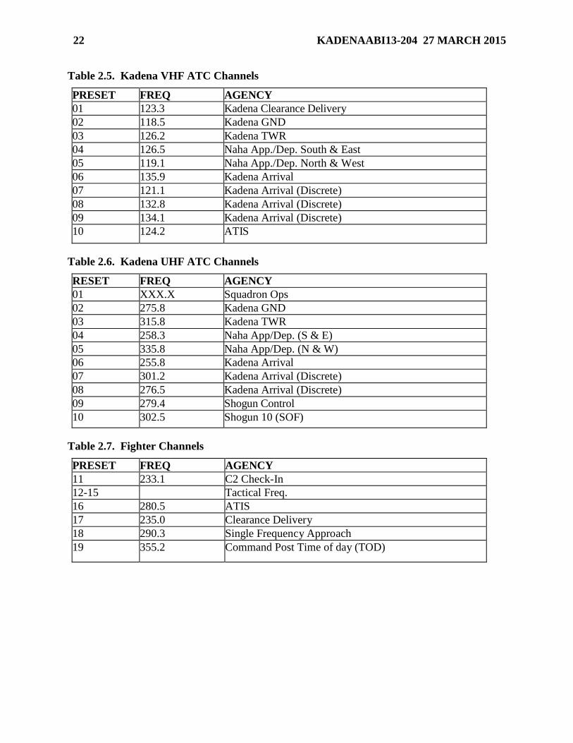
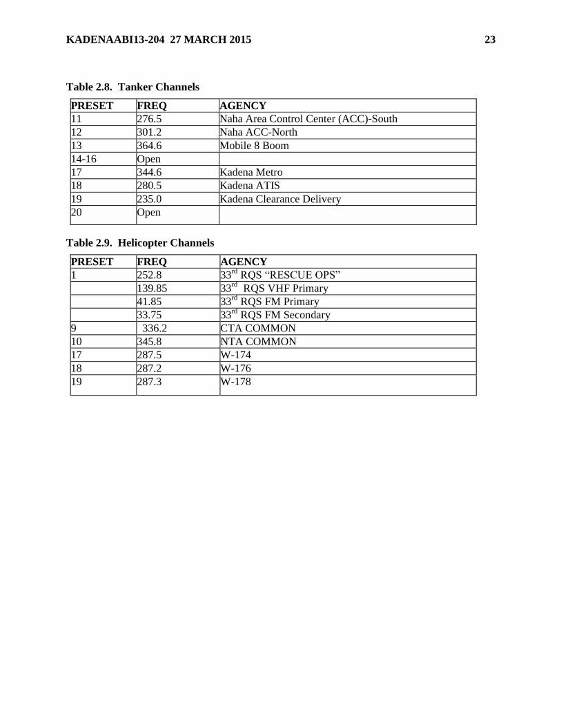
2.25. Local Frequencies/Channelization. Local frequencies and channelization are outlined in
Tables 2.5 through Table 2.9
2.26. Airfield Snow Removal Operations. KAB does not have snow removal capabilities.
Page 22
22 KADENAABI13-204 27 MARCH 2015
Table 2.5. Kadena VHF ATC Channels
PRESET FREQ AGENCY
01 123.3 Kadena Clearance Delivery
02 118.5 Kadena GND
03 126.2 Kadena TWR
04 126.5 Naha App./Dep. South & East
05 119.1 Naha App./Dep. North & West
06 135.9 Kadena Arrival
07 121.1 Kadena Arrival (Discrete)
08 132.8 Kadena Arrival (Discrete)
09 134.1 Kadena Arrival (Discrete)
10 124.2 ATIS
Table 2.6. Kadena UHF ATC Channels
RESET FREQ AGENCY
01 XXX.X Squadron Ops
02 275.8 Kadena GND
03 315.8 Kadena TWR
04 258.3 Naha App/Dep. (S & E)
05 335.8 Naha App/Dep. (N & W)
06 255.8 Kadena Arrival
07 301.2 Kadena Arrival (Discrete)
08 276.5 Kadena Arrival (Discrete)
09 279.4 Shogun Control
10 302.5 Shogun 10 (SOF)
Table 2.7. Fighter Channels
PRESET FREQ AGENCY
11 233.1 C2 Check-In
12-15 Tactical Freq.
16 280.5 ATIS
17 235.0 Clearance Delivery
18 290.3 Single Frequency Approach
19 355.2 Command Post Time of day (TOD)
Page 23
KADENAABI13-204 27 MARCH 2015 23
Table 2.8. Tanker Channels
PRESET FREQ AGENCY
11 276.5 Naha Area Control Center (ACC)-South
12 301.2 Naha ACC-North
13 364.6 Mobile 8 Boom
14-16 Open
17 344.6 Kadena Metro
18 280.5 Kadena ATIS
19 235.0 Kadena Clearance Delivery
20 Open
Table 2.9. Helicopter Channels
PRESET FREQ AGENCY
1 252.8 33rd
RQS “RESCUE OPS”
139.85 33rd
RQS VHF Primary
41.85
33rd
RQS FM Primary
33.75 33rd
RQS FM Secondary
9 336.2 CTA COMMON
10 345.8 NTA COMMON
17 287.5 W-174
18 287.2 W-176
19 287.3 W-178
Page 24
24 KADENAABI13-204 27 MARCH 2015
Chapter 3
FLIGHT PLANNING
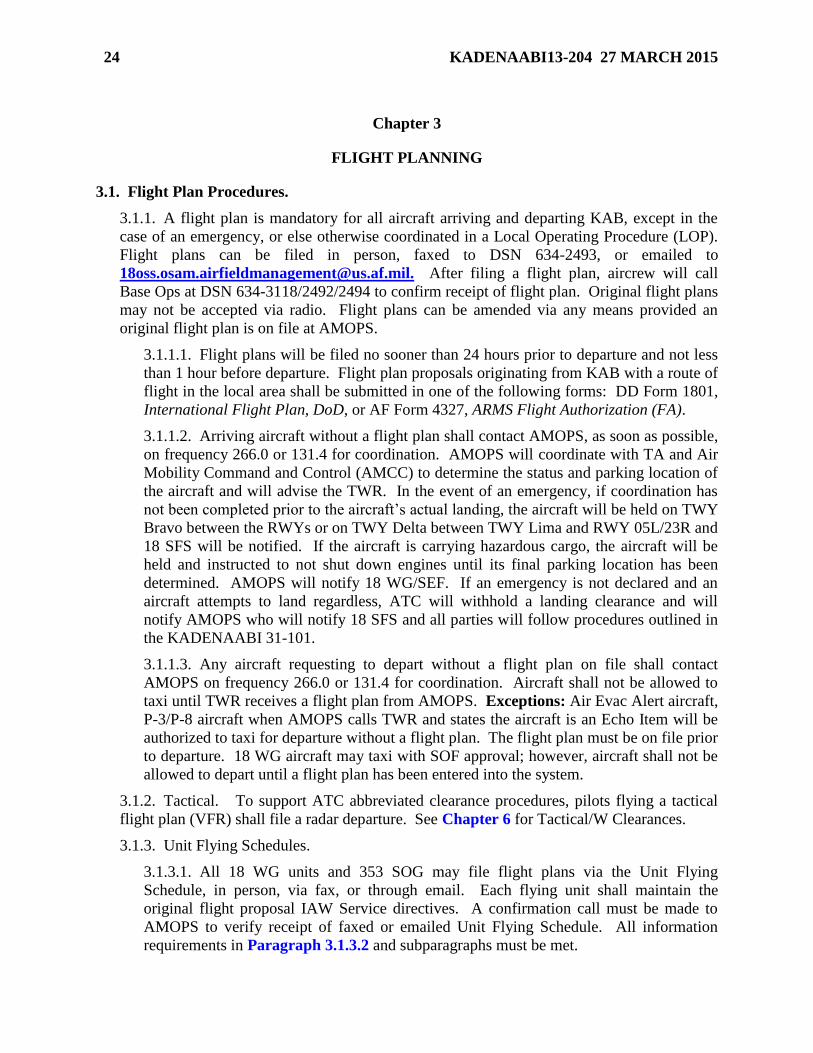
3.1. Flight Plan Procedures.
3.1.1. A flight plan is mandatory for all aircraft arriving and departing KAB, except in the
case of an emergency, or else otherwise coordinated in a Local Operating Procedure (LOP).
Flight plans can be filed in person, faxed to DSN 634-2493, or emailed to
[email protected] . After filing a flight plan, aircrew will call
Base Ops at DSN 634-3118/2492/2494 to confirm receipt of flight plan. Original flight plans
may not be accepted via radio. Flight plans can be amended via any means provided an
original flight plan is on file at AMOPS.
3.1.1.1. Flight plans will be filed no sooner than 24 hours prior to departure and not less
than 1 hour before departure. Flight plan proposals originating from KAB with a route of
flight in the local area shall be submitted in one of the following forms: DD Form 1801,
International Flight Plan, DoD, or AF Form 4327, ARMS Flight Authorization (FA).
3.1.1.2. Arriving aircraft without a flight plan shall contact AMOPS, as soon as possible,
on frequency 266.0 or 131.4 for coordination. AMOPS will coordinate with TA and Air
Mobility Command and Control (AMCC) to determine the status and parking location of
the aircraft and will advise the TWR. In the event of an emergency, if coordination has
not been completed prior to the aircraft’s actual landing, the aircraft will be held on TWY
Bravo between the RWYs or on TWY Delta between TWY Lima and RWY 05L/23R and
18 SFS will be notified. If the aircraft is carrying hazardous cargo, the aircraft will be
held and instructed to not shut down engines until its final parking location has been
determined. AMOPS will notify 18 WG/SEF. If an emergency is not declared and an
aircraft attempts to land regardless, ATC will withhold a landing clearance and will
notify AMOPS who will notify 18 SFS and all parties will follow procedures outlined in
the KADENAABI 31-101.
3.1.1.3. Any aircraft requesting to depart without a flight plan on file shall contact
AMOPS on frequency 266.0 or 131.4 for coordination. Aircraft shall not be allowed to
taxi until TWR receives a flight plan from AMOPS. Exceptions: Air Evac Alert aircraft,
P-3/P-8 aircraft when AMOPS calls TWR and states the aircraft is an Echo Item will be
authorized to taxi for departure without a flight plan. The flight plan must be on file prior
to departure. 18 WG aircraft may taxi with SOF approval; however, aircraft shall not be
allowed to depart until a flight plan has been entered into the system.
3.1.2. Tactical. To support ATC abbreviated clearance procedures, pilots flying a tactical
flight plan (VFR) shall file a radar departure. See Chapter 6 for Tactical/W Clearances.
3.1.3. Unit Flying Schedules.
3.1.3.1. All 18 WG units and 353 SOG may file flight plans via the Unit Flying
Schedule, in person, via fax, or through email. Each flying unit shall maintain the
original flight proposal IAW Service directives. A confirmation call must be made to
AMOPS to verify receipt of faxed or emailed Unit Flying Schedule. All information
requirements in Paragraph 3.1.3.2 and subparagraphs must be met.
Page 25
KADENAABI13-204 27 MARCH 2015 25
3.1.3.1.1. Kadena Partner/USAF rotational units, Marine Wing Liaison Kadena
(MWLK) and U.S. Navy (USN) rotational units may file flight plans via Unit Flying
Schedule, in person, by fax or by email. Upon arrival, the unit shall coordinate flight
plan requirements with the AFM and confirm understanding of all requirements in
Paragraph 3.1 and all subparagraphs. This will negate the need for a separate Letter
of Agreement. Each flying unit shall maintain the original flight proposal IAW
Service directives. A confirmation call must be made to AMOPS to verify receipt of
faxed or emailed Unit Flying Schedule. All information requirements in Paragraph
3.1.3.2 and subparagraphs must be met. Note: Rotational units that have not
coordinated with the AFM are not authorized to fax or email flight proposals.
3.1.3.2. Required items for unit flying schedules:
3.1.3.2.1. Number and Type of Aircraft.
3.1.3.2.2. Call Sign(s).
3.1.3.2.3. Estimated Time of Departure.
3.1.3.2.4. Total Estimated Elapsed Time. As per Naha Area Control Center (ACC)
request, aircraft filing for a terminal delay at Kadena will include mission timing plus
terminal delay timing in block 16, TOTAL estimated elapsed time. Additionally,
aircrews will annotate block 18, OTHER INFORMATION, with a remark stating
estimated terminal delay timing, e.g., RMK/KAD: TRANS 3+00.
3.1.3.2.5. Pilot’s Name.
3.1.3.2.6. Fuel.
3.1.3.2.7. Area of Flight (Warning Areas or local VFR).
3.1.3.2.8. Approval Authority.
3.1.3.2.9. Local Contact Number. Note: A confirmation call must be made to
AMOPS to verify receipt of faxed or emailed flight proposals. If the flight proposal
is faxed or emailed, the submitting organization must maintain the original on file
IAW Service directives.
3.1.4. Units using the AF Form 4327 will deliver, fax or email the signed copy of the form to
AMOPS by the end of the duty day before the effective date. Flying squadrons shall
immediately call, fax, or email all updates and add-ons to AMOPS and 18 WG/CP. Emails
shall be followed up with a phone call. All items in Paragraph 3.1.3.2 must be provided for
each change.
3.1.4.1. Units using Tactical Aircrew Scheduling and Airspace Management System
(TASAMS) will ensure the next day’s flying schedule is approved and in TASAMS by
the end of the duty day (1630L, or 1930L during 18 WG night flying) before the effective
date. Once the flying schedule is in TASAMS, after 1630L/1930L, it is considered
approved by the appropriate flying squadron commander or director of operations. This
approval allows AMOPS to file flight plans with Naha Flight Service Station and ensures
flight plans are entered into the airspace system. All changes after 1630L/1930L for the
schedule/current day of flying must be telephonically coordinated with AMOPS as an
add-on, change or deletion.
Page 26
26 KADENAABI13-204 27 MARCH 2015
3.1.5. During local exercises, aircraft on alert must activate their clearance with AMOPS
prior to launch.
3.1.5.1. Shogun Control/Shogun 10 (SOF) or designated representative will initiate a
flight clearance request via telephone or by radio with AMOPS for alert aircraft only. A
flight plan shall be faxed, emailed or hand delivered to AMOPS as soon as possible.
3.2. Bird and Wildlife Aircraft Strike Hazard (BASH) Program.
3.2.1. BASH Program. The KAB BASH Program is conducted IAW AFI 91-202, The US
Air Force Mishap Prevention Program, AFPAM 91-212, Bird/Wildlife Aircraft Strike
Hazard (BASH) Management Techniques, and KAB Plan 91-212, Kadena Air Base
Bird/Wildlife Aircraft Strike Hazard (BASH) Plan.
3.2.2. Aircrew Responsibility. Aircrews observing or encountering any bird activity that
could constitute a hazard should pass the information to the SOF (Shogun 10: 302.5), TWR,
or 18 WG/CP. The following information is necessary:
3.2.2.1. Aircraft call sign, location, altitude, time.
3.2.2.2. Approximate number and type of bird(s), if known and bird behavior (on
ground, flying to/from a location).
3.2.3. Bird Strikes. Promptly report all bird strikes to 18 WG/SE by completing an AF Form
853, Air Force Wildlife Strike Report.
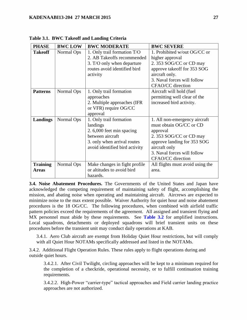
3.3. Bird Watch Conditions (BWC). Aircraft shall comply with BWC procedures outlined
IAW KAB Plan 91-212, additionally BWC Takeoff/Land Criteria Table 3.1
3.3.1. Dissemination. ATC shall disseminate bird activity IAW FAAO JO 7110.65. The
primary means of transmitting BWCs will be via the Automated Terminal Information
Service (ATIS).
Page 27
KADENAABI13-204 27 MARCH 2015 27
Table 3.1. BWC Takeoff and Landing Criteria
PHASE BWC LOW BWC MODERATE BWC SEVERE
Takeoff Normal Ops 1. Only trail formation T/O
2. AB Takeoffs recommended
3. T/O only when departure
routes avoid identified bird
activity
1. Prohibited w/out OG/CC or
higher approval
2. 353 SOG/CC or CD may
approve takeoff for 353 SOG
aircraft only.
3. Naval forces will follow
CFAO/CC direction
Patterns Normal Ops 1. Only trail formation
approaches
2. Multiple approaches (IFR
or VFR) require OG/CC
approval
Aircraft will hold (fuel
permitting well clear of the
increased bird activity.
Landings Normal Ops 1. Only trail formation
landings
2. 6,000 feet min spacing
between aircraft
3. only when arrival routes
avoid identified bird activity
1. All non-emergency aircraft
must obtain OG/CC or CD
approval
2. 353 SOG/CC or CD may
approve landing for 353 SOG
aircraft only
3. Naval forces will follow
CFAO/CC direction
Training
Areas
Normal Ops Make changes in fight profile
or altitudes to avoid bird
hazards.
All flights must avoid using the
area.
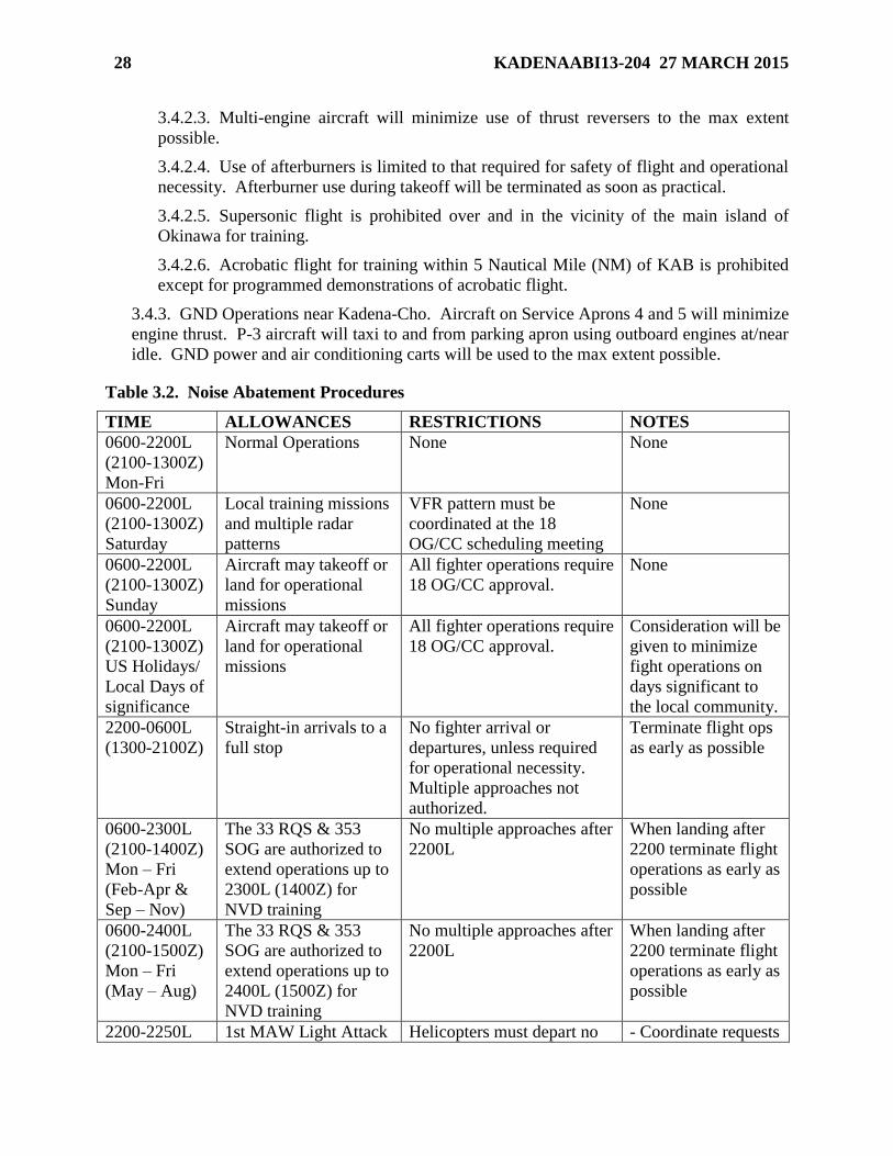
3.4. Noise Abatement Procedures. The Governments of the United States and Japan have
acknowledged the competing requirement of maintaining safety of flight, accomplishing the
mission, and abating noise when operating and maintaining aircraft. Aircrews are expected to
minimize noise to the max extent possible. Waiver Authority for quiet hour and noise abatement
procedures is the 18 OG/CC. The following procedures, when combined with airfield traffic
pattern policies exceed the requirements of the agreement. All assigned and transient flying and
MX personnel must abide by these requirements. See Table 3.2 for amplified instructions.
Local squadrons, detachments or deployed squadrons will brief transient units on these
procedures before the transient unit may conduct daily operations at KAB.
3.4.1. Aero Club aircraft are exempt from Holiday Quiet Hour restrictions, but will comply
with all Quiet Hour NOTAMs specifically addressed and listed in the NOTAMs.
3.4.2. Additional Flight Operation Rules. These rules apply to flight operations during and
outside quiet hours.
3.4.2.1. After Civil Twilight, circling approaches will be kept to a minimum required for
the completion of a checkride, operational necessity, or to fulfill continuation training
requirements.
3.4.2.2. High-Power “carrier-type” tactical approaches and Field carrier landing practice
approaches are not authorized.
Page 28
28 KADENAABI13-204 27 MARCH 2015
3.4.2.3. Multi-engine aircraft will minimize use of thrust reversers to the max extent
possible.
3.4.2.4. Use of afterburners is limited to that required for safety of flight and operational
necessity. Afterburner use during takeoff will be terminated as soon as practical.
3.4.2.5. Supersonic flight is prohibited over and in the vicinity of the main island of
Okinawa for training.
3.4.2.6. Acrobatic flight for training within 5 Nautical Mile (NM) of KAB is prohibited
except for programmed demonstrations of acrobatic flight.
3.4.3. GND Operations near Kadena-Cho. Aircraft on Service Aprons 4 and 5 will minimize
engine thrust. P-3 aircraft will taxi to and from parking apron using outboard engines at/near
idle. GND power and air conditioning carts will be used to the max extent possible.
Table 3.2. Noise Abatement Procedures
TIME ALLOWANCES RESTRICTIONS NOTES
0600-2200L
(2100-1300Z)
Mon-Fri
Normal Operations None None
0600-2200L
(2100-1300Z)
Saturday
Local training missions
and multiple radar
patterns
VFR pattern must be
coordinated at the 18
OG/CC scheduling meeting
None
0600-2200L
(2100-1300Z)
Sunday
Aircraft may takeoff or
land for operational
missions
All fighter operations require
18 OG/CC approval.
None
0600-2200L
(2100-1300Z)
US Holidays/
Local Days of
significance
Aircraft may takeoff or
land for operational
missions
All fighter operations require
18 OG/CC approval.
Consideration will be
given to minimize
fight operations on
days significant to
the local community.
2200-0600L
(1300-2100Z)
Straight-in arrivals to a
full stop
No fighter arrival or
departures, unless required
for operational necessity.
Multiple approaches not
authorized.
Terminate flight ops
as early as possible
0600-2300L
(2100-1400Z)
Mon – Fri
(Feb-Apr &
Sep – Nov)
The 33 RQS & 353
SOG are authorized to
extend operations up to
2300L (1400Z) for
NVD training
No multiple approaches after
2200L
When landing after
2200 terminate flight
operations as early as
possible
0600-2400L
(2100-1500Z)
Mon – Fri
(May – Aug)
The 33 RQS & 353
SOG are authorized to
extend operations up to
2400L (1500Z) for
NVD training
No multiple approaches after
2200L
When landing after
2200 terminate flight
operations as early as
possible
2200-2250L 1st MAW Light Attack Helicopters must depart no - Coordinate requests
Page 29
KADENAABI13-204 27 MARCH 2015 29
(1300-1350Z)
(Mar – Sep)
Helicopters are
authorized to land after
2200L (1300Z) for
NVD ordnance training
later than 2250L (1350Z) via MWLK for
approval
- Ensure aircraft
arrive with sufficient
time for tng &
departure NLT
2250L (1350Z)
- Depart RWY 23,
remain w/in KAB
airspace, avoid
overflight of
populated areas.
Note: Any deviation from Table 3.2 must be approved by the 18 OG/CC through the
scheduling meeting NLT 10 working days prior to the requested period. Missions published to
the 18 WG weekly schedule, 353 SOG weekly schedule, and Navy 48-hour projection message
have been coordinated and approved by the 18 OG/CC. If aircraft are added to the schedule
after publication, they shall coordinate changes with the 18 OG/CC through 18 WG/CP (DSN
634-1800) NLT 2 hours prior to takeoff. 18 WG/CP will notify AMOPS, TWR and APP of
approval/disapproval.
3.5. Prior Permission Required (PPR) Procedures. A valid AMOPS-issued PPR number is
required for all transient aircraft (except AMC, Air Evac, Special Air Missions, and DV-6)
desiring to terminate in a full stop landing at KAB. Permanent party and TDY/ Temporary
Assigned Duty (TAD) personnel on KAB do not require a PPR number. USAF, USN and USA
aircraft must coordinate with TA prior to the issuance of a PPR number. USMC aircraft must
coordinate with MWLK prior to receiving a PPR number. If requester requires cargo or
passenger support coordination with AMCC/ATOC is required prior to issuance of a PPR
number.
3.5.1. Procedures.
3.5.1.1. Prior to issuing a PPR number or accepting an aircraft’s flight plan, AMOPS will
check standard noise restriction criteria and any additional noise restriction NOTAMs to
determine if 18 OG/CC approval is required. If 18 OG/CC approval is required, AMOPS
will instruct the requester to call 18 WG/CP. Note: The 18 OG/CC waiver does not
constitute a PPR number.
3.5.1.2. If the quiet-hours waiver is approved, 18 WG/CP will notify AMOPS for PPR
coordination with TA or MWLK.
3.5.1.3. If the PPR is approved, AMOPS will notify 18 WG/CP. 18 WG/CP will notify
requester and base agencies per the after-hour checklist.
3.5.1.4. 18 WG/CP will instruct requester to call AMOPS for the PPR number.
3.5.1.5. If the quiet-hours waiver is approved, but the PPR is denied, AMOPS will notify
18 WG/CP. 18 WG/CP will notify requester of disapproval.
3.5.1.6. If the quiet-hours waiver is disapproved, 18 WG/CP will notify requester and
base agencies per the after-hour checklist.
Page 30
30 KADENAABI13-204 27 MARCH 2015
3.5.2. Unscheduled/Unauthorized Aircraft Arrivals. In the event of an unscheduled aircraft
arrival, AMOPS will initiate actions contained in AFI 10-1001, Civil Aircraft Landing
Permits. Additionally, all applicable work centers will initiate actions in KADENAABI 31-
101, The Kadena AB Integrated Defense (FOUO), a copy which can be obtained from 18
SFS. For civil aircraft diverts, AMOPS will notify 18 WG/CP to stand up the Kadena
Reception Working Group. For military PPR violations, AMOPS will run a Quick Reaction
Checklist and forward the information to the AOF/CC.
3.6. Distinguished Visitor (DV) Notification Requirements. AM is responsible for
notification of APP of the call sign and type of the DV aircraft. APP will call AMOPS via the
hotline when the aircraft is 50 miles from the airfield. Note: AMOPS is the only 18 WG agency
authorized to request 50-mile-out calls from GCA/TWR/ARR/APP.
3.7. Functional Check Flights (FCF). A FCF aircraft will normally fly standard mission
profiles and require no special handling. Note: Standard takeoff for FCF aircraft is a static
departure. ATC will not solicit rolling/immediate takeoffs from FCF aircraft. Aircrew will
notify ATC of their intentions as a FCF and requirement for a static takeoff.
3.8. Dangerous/Hazardous Cargo. 733 Air Mobility Squadron (AMS) shall notify AMOPS of
aircraft arriving or departing with Hazardous Cargo classified as “Class 6” (Poison), all
explosive classes, and Nuclear Weapon Related Materiel. For non-AMC aircraft, AMOPS shall
obtain hazardous cargo information when the PPR is requested.
3.8.1. When an aircraft carrying hazardous cargo intends to arrive or depart KAB, AMOPS
shall obtain the aircraft call sign, aircraft type, cargo classification, net explosive weight,
estimated arrival time, and estimated departure time. Additionally AMOPS will notify TWR,
Fire Department, 18 WG/CP, 733 AMCC and TA.
3.9. Local Area Orientation for Visiting Units. Units TDY/TAD to KAB that will conduct
training missions in the local area are required to receive a Local Area Orientation (LAO) or
"Course Rules" briefing from 18 OG/OGV (Stan/Eval) or designated representative prior to
conducting regular local training.
3.9.1. LAO briefings and other Stan/Eval information is located on the USAF Sharepoint
under "18 OG Stan/Eval"
(https://kadena.eim.pacaf.af.mil/sites/18%20OG_OGV/default.aspx).
3.9.1.1. LAO briefings shall be reviewed for accuracy by 18 OG/OGV.
3.9.2. Chief, 18 OG/OGV can be contacted at [email protected] or DSN 634-4567.
Page 31
KADENAABI13-204 27 MARCH 2015 31
Chapter 4
LOCAL AIRSPACE
4.1. General Airspace Information. The area within 100 NM of KAB is considered the local
flying area, extended local flying is out 200 NM. Training operations are conducted in the Joint
Okinawa Training Range Complex (JOTRC). The terminal radar service area (TRSA) is within
60 NM of Naha VORTAC and is governed by FAA regulations. Outside the TRSA,
International Civil Aviation Organization (ICAO) rules apply except as noted in FLIP AP3/A.
See Japan Aeronautical Information Publication (AIP) and Joint Okinawa Training Range
Complex (JOTRC) website for additional information.
4.1.1. JOTRC. Local Training Areas are defined by the Joint Okinawa Scheduling Cell
(JOSC). To reserve training areas contact the JOSC (634-4797,
https://kadena.eim.pacaf.af.mil/sites/JOSC/). Aircrew will request permission from
controlling agency prior to entry into JOTRC.
4.2. Controlled Airspace. See Figure A2.6, Figure A2.7, and Figure A2.8 for detailed
diagram.
4.2.1. Classification. Naha Class B will contact APP for ATC instructions. They will
provide aircraft identification, position, altitude and intentions. APP will provide instructions
for the areas overlapping Naha, RODN, and ROTM Class D Airspace.
4.2.1.1. RODN Class D (Japan AIP: Class D Surface Area) (Japan AIP: Control Zone):
The airspace from surface up to but not including 3,000 feet MSL within 5 NM of KAD
VORTAC (N262124, E1274604), excluding the area 3 miles south of RWY 5R/23L,
ROTM Class D Airspace (Surface up to but not including 2,000 feet MSL).
4.2.2. Terminal Radar Service Area.
4.2.2.1. Naha Approach Control: APP provides air traffic services within a 60 NM radius
of Naha VORTAC from surface to 20,000 feet MSL. For details refer to AIP Japan
ROAH AD2-17. Air traffic services are provided for RODN, ROTM, ROAH, ROKJ and
RORA and within 30 NM of the KXC VORTAC, up to and including 16,000 feet MSL.
4.2.2.2. Kadena Arrival Airspace: The airspace delegated by APP for ARR service to
RODN and ROTM. The airspace from 2,000 feet MSL to 6,000 feet MSL within a
rectangular area centered on KAD VORTAC.
4.2.2.2.1. RWY 05: The KAD R-325 out to 10 NM, then left turn 90° southwest
bound to 30 NM. The KAD R-145 out to 10 NM, then right turn 90° southwest
bound to 30 NM, excluding that airspace owned by APP.
4.2.2.2.2. RWY 23: The KAD R-325 out to 10 NM, then right turn 90° northeast
bound to 30 NM. The KAD R-145 out to 10 NM, then left turn 90° northeast bound
to 30 NM excluding that airspace owned by APP.
Page 32
32 KADENAABI13-204 27 MARCH 2015
4.3. Uncontrolled Airspace.
4.3.1. Class E Airspace. That airspace from surface to 700 feet/1,000 feet/2,000 feet Above
GND Level (AGL) to 2,000 feet within 60 NM of KAD VORTAC, excluding the Naha
Class B and Class D airspace.
4.3.2. Class G Airspace. That airspace from surface up to but not including 700 feet, 1,000
feet, and 2,000 feet AGL, with the exclusion of Class D and Naha Class B. Class G airspace
is uncontrolled airspace.
4.4. Restricted Areas. See Figure A2.9 for depiction of airspace and FLIP AP/3A for
additional information. Restricted Area altitudes are listed in Table 4.1
Table 4.1. Restricted Area Altitudes
R-177 R-195
(Schwab)
R-201
R-202
(Central Training Area)
R-203
(White Beach)
R-204
(Courtney)
SFC -
3K SFC - 2K
SFC -
2K SFC - 1K SFC - 1K SFC – 1K
4.4.1. R-201, R-202, R-203, and R-204. U.S. military aircraft may enter and proceed
through these areas without restrictions/coordination. Civil aviation is restricted from using
this airspace.
4.4.2. Warning Areas and Altitude Reservations (ALTRVs) for Air-to-Air Refueling (AAR).
See FLIP AP/3A and Table 4.2 for ALTRV Altitudes and AAR information. See Figure
A2.15 and Table A2.1 for graphical depiction and additional information.
4.5. VFR Local Training Areas.
4.5.1. Departure to off-island airspace or out of the Naha Class B airspace will be via an
established route, clearance or standard radar departure.
4.5.2. ATC radar flight following is mandatory during departure. Radar flight following
after Visual Meteorological Conditions (VMC)-on-top will be requested with either APP or
Ground Control Intercept (GCI).
4.5.3. Southeast Training Area (SETA). The SETA dimensions, procedures, and authorized
users are defined in the Okinawa ATC Agreement Tab A and Tab E. SETA is defined as
the area between NHC VORTAC R-100 and R-160 from 20DME to 42DME (3,000 feet
MSL to FL190).
4.5.3.1. AAR Airspace. See FLIP AP/3A and Table 4.2 for AAR information. See
Figure A2.15 and Table A2.1 for additional details.
4.6. Chaff and Flare Use.
4.6.1. Chaff and self-protection or target illumination flare usage is authorized for all
training ranges. Chaff and flares must be initiated and remain within range boundaries. All
target-illumination flares must burn out at or above 500 feet AGL.
4.6.2. Chaff is not authorized in W-179 or the SHOVEL ALTRV if winds aloft exceed 50kts
unless it is RR-188 chaff.
4.6.3. ATC will immediately notify 18 WG/CP of chaff use that impacts flying operations.
Page 33
KADENAABI13-204 27 MARCH 2015 33
4.6.4. Any unit that violates chaff procedures will not be permitted to use chaff without 18
OG/CC approval.
Table 4.2. Warning Area/ALTRV Altitudes and Standard AAR Information
W-172 (SFC – UNL)
RVIP N2514 E12746 KAD/184/67 Comm Plan Foxtrot
RVCP N2427 E12746 KAD/184/114 Boom 286.8/366.3 A/A 39/102Y
ALT Base Tanker FL240 RDZV 255.9/233.1 Beacon 2-4-0
W-173A (3K – 60K)
RVIP N2709 E12921 KAD/064/97 Comm Plan Alpha
RVCP N2709 E12955 KAD/071/125 Boom 242.4/296.7 A/A 51/114Y
ALT Base Tanker FL240 RDZV 255.9/233.1 Beacon 2-3-1
W-173E (SFC – UNL)
RVIP N2631 E12920 KAD/087/85 Comm Plan Charlie
RVCP N2631 E13005 KAD/089/125 Boom 242.7/296.7 A/A 53/116Y
ALT Base Tanker FL240 RDZV 255.9/233.1 Beacon 2-3-1
W-173F (SFC – UNL)
RVIP N2621 E13040 KAD/094/156 Comm Plan Bravo
RVCP N2700 E13040 KAD/079/160 Boom 242.5/342.2 A/A 52/115Y ALT Base Tanker FL240 RDZV 255.9/233.1 Beacon 3-3-0
W-179 (SFC – UNL)
RVIP N2734 E12725 KAD/350/75 Comm Plan Delta
RVCP N2740 E12618 KAD/319/111 Boom 243.5/324.2 A/A 54/117Y
ALT Base Tanker FL 240 RDZV 255.9/233.1 Beacon 4-0-0
W-185 (SFC – UNL)
RVIP N2535 E12909 KAD/126/88 Comm Plan Hotel
RVCP N2508 E12955 KAD/127/137 Boom 229.2/364.6 A/A 18/81Y
ALT Base Tanker FL240 RDZV 255.9/233.1 Beacon 3-1-1
BUBBA ALTRV
RVIP N2714 E12529 KAD/298/133 Comm Plan India
RVCP N2651 E12439 KAD/285/170 Boom 233.6/229.3 A/A 20/83Y
ALT Base Tanker FL240 RDZV 255.9/233.1 Beacon 5-0-0
Mobile 9 East (5.5K – 40K)
RVIP N2500 E12845 KAD/151/97 Comm Plan Echo
RVCP N2415 E12845 KAD/161/137 Boom 394.9/234.3 A/A 56/119Y ALT Base Tanker FL240 RDZV 255.9/233.1 Beacon 4-1-1
Mobile 9 South (5.5K- 40K)
RVIP N2424 E12735 KAD/189/117 Comm Plan Echo
RVCP N2400 E12830 KAD/168/146 Boom 394.9/234.3 A/A 56/119Y ALT Base Tanker FL240 RDZV 255.9/233.1 Beacon 4-1-1
TRINITY ALTRV (5.5K- 40K)
RVIP N2709 E13022 KAD/075/147 Comm Plan Alpha
RVCP N2709 E13045 KAD/077/167 Boom 242.4/296.7 A/A 51/114Y
Page 34
34 KADENAABI13-204 27 MARCH 2015
ALT Base Tanker FL240 RDZV 255.9/233.1 Beacon 2-3-1
STOUT ALTRV (5.5K- 40K)
RVIP N2628 E13106 KAD/091/180 Comm Plan Alpha RVCP N2655 E13106 KAD/083/182 Boom 242.4/296.7 A/A 51/114Y ALT Base Tanker FL240 RDZV 255.9/233.1 Beacon 2-3-1
Page 35
KADENAABI13-204 27 MARCH 2015 35
Chapter 5
GROUND OPERATIONS
5.1. Controlled Movement Area (CMA). All aircraft, vehicles and approved pedestrian traffic
on the CMA require 2-way radio communications, as well as approval from TWR. In the event
of lost communications, light gun signals will be used. If use of light gun signals is unsuccessful
controlling vehicle or pedestrian traffic, ATC will flash the RWY lights at five second intervals
(at highest intensity) instructing all vehicles, equipment, and personnel to exit the RWY without
delay. As a last resort, ATC will contact AMOPS and request escort vehicles assistance.
5.2. Lightning Procedures.
5.2.1. The control TWR will broadcast “LIGHTNING OBSERVED WITHIN [5/10 NM]”
on all appropriate frequencies and nets. TWR will update the ATIS with all WX advisories.
5.2.2. Lightning within 10 NM. Aircraft holding short of the active runway awaiting takeoff
should only accomplish a takeoff if the thunderstorm activity is not within 10NM of the
intended flight path. Arriving aircraft will hold if the thunderstorm activity is within 10 NM
of the arrival or missed approach corridor (i.e. intended flight path). Aircrew should expect
to taxi back to parking for shelter. Personnel operating on the flightline should cease all
outside activity and seek shelter. MX will begin clearing the flightline at this time. All
aircraft servicing and MX activities will cease until the lightning warning is lifted. ATC will
be directive.
5.2.3. Lightning within 5 NM. Discontinue all takeoffs and landings. The flightline will
be clear of all personnel. All arriving aircraft will hold until either “LIGHTNING WITHIN
5NM” of KAB has been lifted or aircraft reach divert fuel. Pilots will coordinate with the
SOF or OPS Supervisors, as applicable, for diverts to a suitable alternate airfield prior to
reaching divert fuel. If on the ground, pilots should expect to hold on the ground without
chocks until the lightning threat passes. MX will not go outside to chock aircraft.
5.3. Aircraft Parking Plan. Primary parking spots for 18 WG, partner units, and transient
aircraft IAW Table 5.1. AMOPS will approve changes to the parking plan.
Page 36
36 KADENAABI13-204 27 MARCH 2015
Table 5.1. Primary Assigned Parking Spots
Unit Location Overflow
44 FS ND 4 (Bldg 830), 5 (Bldg 831), 8 (Bldg 834), UFR Flow-Thrus
1-25
67 FS ND 1 (Bldg 812), 2 (Bldg 814), 3 (Bldg 816), UFR Flow-Thrus
26-50
44 AMU Protective Aircraft Shelter (PAS) 5-11
67 AMU PAS 1-4, 12-15
909 AMU L9-L13, M1-M3, N2, N3, N5, N6, N7, N9 P17, P19,
L81
961 AMU N10, N11, N12
18 EMS T1-T6, Ops 1 (DV Spot), 2, 3, HS:102, 104, 106, 108, 110, 112,
114, 117, 119, 121, 302
733 AMS SA-12, 2, Hazardous Cargo: TWY B-South w/AMOPS approval.
82 RS N13, N14, N15 Coord w/909
353 SOG L1-L8, N1, Hangar 3539 and Hangar 3671 Coord w/
AFM
33 RQS Area in front of Hangar 3534 P – AFM
apprvl
MWLK HS111, 113, 115, 201, 203-208, 210, 304, 306, 308, 310, 312,
313, 314 Harrier Trim Pad
CFAO Hangar 3667, Hangar 3672, N14-N15 for PL2 assets
CTG SA4, SA5
18FSS
(Aero
Club)
HS 401, 402
18 OG HS 122-126, 319, 321, 326, 330, 331, 332, P1-19, Eagle Trim
Pad
18 MUNS HS 333
Note:
1. U s e d b y t h e 353 SOG, but available to 909 AMU when all KC-135 aircraft are at
KAB or when Protection Level 2 (PL2) overflow parking is required.
2. Due to the hazard of jet blast while taxiing into parking, no Aerospace GND Equipment
(AGE) or personnel will be present servicing aircraft on SA 1, Spot 1B, while an aircraft is
taxiing to park in Spot 1C.
5.3.1. Restricted Parking spots. P1-P15 are usable with AFM approval. The AFM must
evaluate each request and consult with the pavements engineer as needed. If TWY Bravo
South is needed for parking, MX will coordinate with AMOPS NLT 2 hours prior to use.
5.3.2. Explosive Cargo Storage and Parking Areas.
5.3.2.1. Designated hazardous cargo parking areas are TWY Bravo South, TWY Bravo
Center (contingencies), and TWY Delta North (helicopters). Additional hazardous
cargo/explosives parking limits are in the Explosives Loaded Aircraft Parking Plan.
Page 37
KADENAABI13-204 27 MARCH 2015 37
5.3.2.2. Parking or storage of explosives in amounts greater than specified or outside
authorized areas, must be approved by 18 WG/SEW, the parking spot owner, and AFM.
5.3.2.3. Coordinate with AFM and 18 WG/SE to use TWY Bravo or Delta for an
explosive cargo parking area.
5.3.3. F-16 Hydrazine Emergency Parking Areas. Aircraft with suspected hydrazine leaks or
Emergency Power Unit (EPU) activation will be directed to exit the RWY at TWY Bravo or
Echo and stop between RWYs. Alternate parking locations are TWYs Alpha or Foxtrot
between RWYs. Any aircraft taxiing near a hydrazine aircraft will be instructed by
ATC to utilize 100% oxygen. 18 MOCC will coordinate with AMOPS for use of the
area(s) and will advise with the start and termination of MX. AMOPS will publish a
NOTAM closing the area to all aircraft and unrelated vehicles.
5.3.4. Upper Fighter Ramp (UFR). The UFR is specifically designed and marked for fighter
type aircraft (wingspan less than 45 feet). Taxi lines provide at least a 10 foot clearance from
all obstacles behind the yellow wingtip clearance line. Pilots will comply with AFI 11-218,
Aircraft Operations and Movement on the Ground, and Mission Design Series (MDS)
specific directives when taxing on the UFR.
5.3.5. PL2 Asset Parking. PL2 parking spots are N10-N15. PL2 overflow parking spots are
M1-M3 and L12-L13. Parking spot priority will by M3, M2, L12, L13 then M1. M1 is an
alternate fuel cell MX location and must remain available to the maximum extent practical.
5.3.6. Operation Row Spot Parking Coordination. When ops row is used for aircraft with
wingspan of 99ft or greater, MX personnel must remove all equipment and vehicles along the
concourse walkway. MX personnel will coordinate with AMOPS and position a wing walker
along the concourse during taxi.
5.3.7. Overflow Parking: TWY Bravo South is designated as overflow parking for wide
body aircraft, coordinate parking approval with AFM.
5.4. Aircraft Taxiing Requirements/Routes. See Chapter 9 through Chapter 11 for aircraft
specific guidance.
5.4.1. Taxi Restrictions.
5.4.1.1. After a major mishap (actual or exercise) the on scene commander will establish
an initial cordon and notify TWR.
5.4.1.2. GND will delay taxi of large aircraft (B-747, C-5, KC-10, E-4, etc.) from SAs
and parking spots when jet blast may affect landing/departing aircraft.
5.4.1.3. Coordination with Navy (634-6560) and AMOPS for repositioning of aircraft on
SAs 4 and 5 must be accomplished to ensure unrestricted taxi operations.
5.4.1.4. 733 AMS marshallers are required on TWY Kilo when parking aircraft on SA-1.
Marshallers shall give way to any aircraft already taxiing on TWY Kilo.
5.4.1.5. MV-22 aircraft are prohibited from taxiing on TWY Charlie, Delta between
RWY 05/R-23L and Lima, Echo, and Kilo between Delta and Foxtrot. MV-22 aircraft
may taxi over TWY Kilo, between Delta and Foxtrot but may not stop on the asphalt
while engines are running. These restrictions are due to high exhaust temperatures.
Page 38
38 KADENAABI13-204 27 MARCH 2015
5.4.2. Weight Bearing Limitations.
5.4.2.1. AFM will be consulted 72 hours prior to aircraft operations above weight
limitations listed on Airfield Suitability Report. AFM will develop taxi routing for large
aircraft (B-737/C-40/P-8A, etc) from service aprons and parking spots when their jet
blast may affect landing/departing aircraft on RWY.
5.4.2.2. The 18 OG/CC has delegated the approval authority for weight bearing waivers
to the AFM. AFM will obtain a recommendation from 718 CES Pavements Engineer
prior to approving a waiver.
5.4.2.3. TWY Foxtrot between the RWYs is closed to B-52 aircraft >265,000 lbs.
5.4.3. Wing Tip Clearance Restrictions. See Table 5.2 and Figure A2.5 for requirements
and restrictions.
5.5. Aircraft Towing. Aircraft tows are conducted IAW AFI 13-213 KADENAABSUP. All
aircraft tows require 2-way radio contact and TWR approval. Note: All tow operators must give
way to taxiing aircraft.
Table 5.2. Wing Tip Clearance Restrictions
Location Max Wingspan
UFR, TWY D south of J, TWY E south of G,TWY G between Bldg. 3433
and TWY D, Northeast Connector south of TWY G, TWY H
45 feet1
TWY G, between TWY E and Bldg 3433 135 feet
TWY G, between TWY E and TWY F 35 feet
TWY K between TWYs D and F 170 feet2
TWY J 135 feet
TWY L between TWYs A and D 150 feet3
TWY L between D and F w/aircraft parked on SA4 or SA5 135 feet4
TWY ways M, N, P 150 feet
1. Yellow lines provide 10 foot clearance from obstacles.
2. Wingspans > 170 feet require AFM approval.
3. Unless approved by AFM.
4. Wingspans > 150 Feet require wing walkers.
5.6. Engine Test/Run-ups. All engine-runs will be requested through MOCC (634-4139).
MOCC will coordinate with AMOPS (634-3118), TWR and BDOC (634-2475). USN
Commander Fleet Activity Okinawa (CFAO) may approve P-3/P-8A/EP-3/C-2 aircraft engine
runs for mission essential write-ups. Maintainers and MOCC are responsible for engine-
runs including adherence to noise abatement procedures. See Table 5.3 for aircraft specific
procedures and locations.
Page 39
KADENAABI13-204 27 MARCH 2015 39
Table 5.3. Engine Run Approved Locations, Times, and Power Settings
Type
Power
Location
Fighters ≤80% UFR (hardened shelters, HS
(1,2), lower ramp)
>80% Eagle Trim Pad
RC/KC-135 ≤62% L, M, N Row, Warm-Up Pad 1, TWY B North
≤80% L12, L13, M Row, N2, N6, N10-N15, Warm-Up Pad 1,
TWY B North4 2 Eng at TRT
3
E-3/WC-135
≤80% N/M Rows, L TWY
>80% TWY B North
4
2 Eng at TRT
HH-605
100% Helo Spots 1-3, P Row 1, 1-A and 3 AV-8 ≤100% Harrier Trim Pad (Mon – Fri: 0830L – 1630L) C-12 ≤80% SA4, SA5 C-130 ≤100% TWY L, Warm-Up Pad C-17 ≤100% SA1
7, TWY B South
6, TWY B North
4, SA2
8
C-5, B-747, KC-10,
and similar airframes ≤100% SA1
7, TWY B South
6, TWY B North
4
P-3/P-8 ≤100% Warm-Up Pad 1
All
Other MDS
≤100% L Row
Power runs As determined by 733 MOCC with AM approval
4 Eng power
runs
Warm-Up Pad 1, TWY B North4
1. Note:
2. 1. Power >80% HS111, 113, 115, 117,119, 121, 123, & 125 require radio contact with TWR.
3 . 2. Full engine run-ups are permitted on HS equipped with blast deflectors or revetments.
4 . 3. Aircraft run to MRT/TRT in revetments will be towed forward until outboard engines are even
with forward edge of revetment wall on both sides.
5 . 4. Orient aircraft heading 050. 05L/23R and TWY L (between TWY B and TWY A), will be
closed due to FOD and jet blast. AMOPS will conduct a FOD sweep prior to resuming ops.
6 . 5. HH-60 engine runs for post-flight wash may be conducted up to 2 hours after landing.
7. 6. Orient aircraft heading 060. 05R/23L and TWY B Center will be closed. Aircraft may also
be oriented with nose toward 05R/23L and aligned 45 degrees off taxi line. M ax power will be
2 engines <90% and 2 engines at idle. (MX Ops Officer/Sup approval). TWY K and TWY B
intersection will be closed. AMOPS will conduct a FOD sweep prior to resuming ops.
8. 7) Orient aircraft heading toward TWY K. 05R/23L will be closed. AMOPS will conduct a
FOD sweep prior to resuming ops. Power >80% require radio contact with TWR.
9. 8) Requires 18 OG/CC approval.
5.6.1. Hours. Engine runs may be conducted Mon – Sat: 0600L - 2200L and Sun/holidays:
1200L – 1800L. Normal engine-run hours may be restricted by NOTAM(s). Engine-runs
outside normal hours or when a NOTAM is published require 18 OG/CC approval.
Waiver requests for outside normal hour engine-runs are through 18 WG/CP (634-
1800/311.0). Exception: 733 AMS/CC, CFAO, and 353 SOG/CC are the waiver authorities
for Mission Essential write-ups on aircraft they control.
Page 40
40 KADENAABI13-204 27 MARCH 2015
5.6.2. Procedures. MX personnel will contact GND Control prior to engine run – providing
tail number parking row, spot and will monitor GND Control frequency (275.8) at all times
during the engine run. Engine run-ups will take place in hush houses and engine test cells to
max extent possible (no quiet hour restrictions). MX personnel performing run-ups will clear
the area and control vehicles passing behind the aircraft. When engine run-up turbulence is a
hazard to aircraft, the TWR will terminate the engine run-up or detour aircraft. MX
personnel will ensure FOD is removed following the engine-run. Prohibited run-up
locations: HS 102, Spots 1-5 on Ops Row, SA2, and Spot A.
5.7. Hot Brake, Jammed Gun, Hot Pit, and Arm/De-Arm Areas.
5.7.1. Hot Brake/Jammed Gun Areas. Hot Brake/Jammed Gun locations are located on
Warm-Up Pads 1-4 (See Figure A2.3). Alt Hot Brake Area: TWY Bravo Center and Echo
Center. See Paragraph 7.7 for hot brake procedures. Refer to Chapter 9 (fighter) and
Chapter 11 (helicopter) for jammed gun procedures based on MDS.
5.7.2. Hot Pit Refueling Areas/Procedures. Refer to Chapter 9 (fighter) and Chapter 11
(helicopter) for expanded procedures.
5.7.3. Arming/De-Arming Areas and Headings. To be used by aircraft possessing forward
firing ordnance as indicated in Table 5.4
Table 5.4. Arm/De-Arm Area and Heading
Location Heading Location Heading
Warm-Up Pad 1 230 Warm-Up Pad 3 050
Warm-Up Pad 2 070 Warm-Up Pad 4 230
TWY D North 225
5.8. Aircraft Anti-Hijacking. All KAB flightline personnel will be alert to unauthorized
movement or theft of aircraft. Strange behavior of person(s) in parking areas will be reported to
security forces immediately. Suspicious persons will be challenged and detained pending
arrival of proper authority. Unusual/unannounced MX-related engine starts or aircraft
movements without exterior aircraft lights, without an aircraft marshaller or run-up crew, will be
reported immediately to 18 WG/CP. If more immediate action appears warranted, a Security
Incident will be reported to BDOC (Helping Hand Hotline at 634-4444). Security will be
provided to all aircraft on KAB to prevent access from unqualified/unauthorized persons.
Specific anti-hijacking instructions are contained in FAAO JO 7610.4, Special Operations
(FOUO), and KADENAABI 31-101. ATC will be familiar with AFI 13-207, Preventing and
Resisting Aircraft Piracy (Hijacking).
5.9. Radar Warning Receiver/Identification Friend or Foe (RWR/IFF) Check
Responsibilities. 18 WG/MOCC will notify Airfield Management of scheduled RWR/IFF
checks and locations. AMOPS will issue a NOTAM and impose restrictions for aircraft, if
required. Upon completion of the checks, the unit will inform 18 WG/MOCC when all
equipment and personnel are cleared from the area and the TWYs are cleared. 18 WG/MOCC
will then notify AMOPS to cancel the related NOTAM, if published. All equipment shall be
removed immediately once RWR/IFF checks are complete.
Page 41
KADENAABI13-204 27 MARCH 2015 41
Chapter 6
GENERAL FLYING OPERATIONS
6.1. Reduced Same RWY Separation (RSRS). RSRS is authorized IAW with AFI 13-204V3
PACAFSUP. See Table 6.1 and Table 6.2 for RSRS operations.
6.1.1. RSRS not authorized for heavy aircraft.
6.1.2. All aircraft must maintain at least 500 feet lateral or vertical separation when over
flying aircraft on the RWY. Responsibility for separation rests with the pilot.
6.1.3. RSRS does not relieve the pilot of responsibility for wake turbulence separation.
6.1.4. RWY separation within the flight (similar or dissimilar) rests with the individual
elements. This requirement does not preclude ATC from taking action in the event of an
unsafe condition.
6.1.5. RSRS will not be applied to emergency aircraft or when either aircraft involved has
been cleared for the option or when braking action reports of less than fair are reported.
6.1.6. F-18 and AV-8 aircraft shall rollout to the end of the RWY, maintaining rollout speed,
unless authorized otherwise by TWR for early turnoffs or 60 Knots Indicated Airspeed
(KIAS) landings. During normal operations, vertical takeoffs and landings are authorized
under emergency conditions only; however, when crosswinds are out of limits for AV-8s to
perform normal takeoffs and landings (20 knots), the SOF has the authority to approve
vertical takeoffs and landings if TWR is able to sequence them into the traffic pattern.
6.1.7. Aircraft may request an early turn off at TWY Bravo/Whiskey if safing is not required
and flight size is not more than two aircraft (this flight size restriction does not apply to AV-
8s). This request should be made to TWR as soon as possible for planning purposes.
Table 6.1. Daytime RSRS Standards
Pairings
FS
behind
TG
FS
behind
LA
LA
behind
LA
FS
behind
FS
LA
behind
FS
TG
behind
TG
TG
behind
LA
Same Fighter-Type* 3,000’ 3,000’ 3,000’ 3,000’ 6,000’ 3,000’ 3,000’
Dissimilar Fighter-Type + + + 6,000’ 6,000’ + +
Same, Non-Heavy, Non-
Fighter Type
+ + + 6,000’ + + +
Same-Type Aircraft
Formations
+ + + 6,000’ + + +
Fighter-Type behind Non-
Heavy, Non-Fighter Type
+ + + 9,000’ + + +
Non-Heavy, Non-Fighter
Type behind Fighter Type
+ + + 9,000’ + + +
+: Standard FAAO JO 7110.65 separation will be provided
*: For any separations less than 6,000,’ reference Para 7.12.1.9.
Page 42
42 KADENAABI13-204 27 MARCH 2015
Table 6.2. Nighttime RSRS Standards
Pairings
FS
behind
TG
FS
behind
LA
LA
behind
LA
FS
behind
FS
LA
behind
FS
TG
behind
TG
TG
behind
LA
Same Fighter-Type + + + 6,000’ 9,000’ + +
Same, Non-Heavy, Non-
Fighter Type
+ + + 6,000’ + + +
Same-Type Aircraft
Formations
+ + + 6,000’ + + +
Fighter-Type behind Non-
Heavy, Non-Fighter Type
+ + + 9,000’ + + +
Non-Heavy, Non-Fighter
Type behind Fighter Type
+ + + 9,000’ + + +
+: Standard FAAO JO 7110.65 separation will be provided
6.2. Intersection Departures. Intersection departures may be authorized by the TWR from any
intersection if the pilot concurs and traffic flow permits. Intersection departure procedures will
be IAW FAAO JO 7110.65. TWR will issue appropriate distance remaining from the
intersection to military aircraft. Distances are identified in Table 6.3 Pilots are responsible for
determining that sufficient RWY length is available to permit safe takeoff and that the
intersection takeoff is authorized by unit directives.
Table 6.3. Intersection Departure Distance
Intersection Departure Distance
05L 05R 23L 23R
TWY BRAVO 9,300 feet 9,700 feet 2,300 feet 2,700 feet
TWY CHARLIE 7,800 feet 8,200 feet 3,800 feet 4,200 feet
TWY DELTA 5,700 feet 6,400 feet 5,600 feet 6,300 feet
TWY ECHO 2,600 feet 3,700 feet 8,300 feet 9,400 feet
TWY WHISKEY N/A 1,750 feet 10,300 feet N/A
6.3. Reporting. Kadena air traffic controllers will give instructions requiring a distance in
Distance Measuring (DME) range from Kadena. Pilots will make position reports to ATC using
Radial and DME from Kadena.
6.4. Departures. Additional information for VFR/IFR departures is located in Paragraph 6.11
and Paragraph 6.15.
6.4.1. Departure Altitude Restriction. All aircraft, unless otherwise directed, safety of flight
dictates or publication directive will maintain below 1,300 feet MSL until passing the
departure end the RWY.
6.4.2. Whiskey Clearances (Local Stereo Clearances to/from Warning Areas). Pilots shall
depart on a local IFR clearance issued by Clearance Delivery via the published JILEE #
(RWY 05) or TUCOF # (RWY 23) standard instrument departure procedure. See current
DoD FLIP for #. Note: Pilots will be cleared to the entry/exit fix (OTIMI, ELSOL, ZIDEN,
JUMTI or UKIKA) associated with the requested warning area. Example: “COCK01
Page 43
KADENAABI13-204 27 MARCH 2015 43
cleared to ZIDEN via JILEE # departure, RADAR vectors/direct ZIDEN, maintain 10,000
feet expect FL190, departure frequency local channel 4, squawk XXXX”. See Table 6.4 for
defined entry/exit fix locations.
Table 6.4. Entry/Exit Fix Locations
Local Entry/Exit Fix From KAD TACAN LAT / LONG
ELSOL KAD 075 / 40 N 26 34.4 / E 128 28.1
ZIDEN KAD 097 / 40 N 26 19.3 / E 128 30.3
JUMTI KAD 120 / 35 N 26 06.0 / E 128 21.1
OTIMI KAD 325 / 35 N 26 48.7 / E 127 21.5
UKIKA KAD 175 / 35 N 25 46.7 / E 127 52.2
6.4.3. Aircraft requesting to depart as a non-standard formation must advise GND or TWR
prior to taxiing. Notifying GND as soon as possible will prevent departure delays. The last
element and/or aircraft must squawk code 5300 on departure.
6.5. Arrivals. Additional information for VFR/IFR arrivals is located in Paragraph 6.12 and
Paragraph 6.16. This section covers general arrival procedures.
6.5.1. All aircraft exiting the Warning Areas shall contact APP at the appropriate recovery
entry/exit fix.
6.5.2. Fighter aircraft assigned to KAB are automatically cleared to enter the Naha Class B
airspace upon radar identification and initial control instruction. Pilots will maintain VFR
until an IFR clearance is issued (Example: “CLEARED TO KADENA VIA (routing – radar
vectors or direct to KAD) MAINTAIN (altitude).”)
6.5.3. Due to APP radar capabilities, arriving VFR-On-Top aircraft will recover squawking
the recover discrete beacon code issued with their clearance. Aircraft not assigned a discrete
beacon code (e.g., Bat 2 recovers prior to lead), will recover squawking 5400. APP will then
assign a discrete beacon code. This enables the ATC radar to display call sign, beacon code,
altitude, GND speed, and other information to expedite the flow of traffic.
6.6. Standard Radar Climb-Out Instructions. The following subparagraphs are standard
climb-out instructions for aircraft re-entering or remaining in the radar pattern for multiple
approaches. KAB aircraft/TDY units should expect to hear “EXECUTE STANDARD RADAR
CLIMB-OUT” when conducting multiple instrument approaches. If required, the controller may
issue alternate climb-out instructions. Aircrew will follow controller alternate climb-out
instructions.
6.6.1. RWY 23. After completing (type landing), cross departure end of the RUNWAY at or
below ONE THOUSAND THREE HUNDRED, MAKE CLIMBING RIGHT turn heading
THREE SIX ZERO WITHIN TWO D-M-E, climb and maintain THREE THOUSAND.
Note: Delay in climb and turn may result in conflict with arriving aircraft to Naha RWY 18.
6.6.2. RWY 05. After completing (type landing), cross departure end of the RUNWAY at or
below ONE THOUSAND THREE HUNDRED, MAKE CLIMBING LEFT turn heading
THREE SIX ZERO WITHIN TWO D-M-E, climb and maintain THREE THOUSAND.
Page 44
44 KADENAABI13-204 27 MARCH 2015
CLIMB GRADIENT TWO HUNDRED THIRTY FEET PER NAUTICAL MILE UNTIL
LEAVING ONE THOUSAND.
6.7. Breakout/Go-Around/Missed Approach Procedures.
6.7.1. BREAKOUT is an instruction used to direct aircraft out of the approach stream. It
means that an aircraft may no longer continue its approach due to an imminent situation (e.g.,
overtaking another aircraft on final, conflicting IFR/VFR traffic, etc.) and must be turned.
6.7.1.1. An aircraft that is issued BREAKOUT instructions prior to entering Class D
airspace shall be turned to avoid entering Class D airspace.
6.7.1.2. Breakouts within Class D airspace will only be issued as a last resort to avoid a
conflict.
6.7.1.2.1. RWY 05 – “BREAKOUT, TURN LEFT HEADING 360, CLIMB AND
MAINTAIN 2,000 FEET IMMEDIATELY, (reason for breakout),
ACKNOWLEDGE.”
6.7.1.2.2. RWY 23 – “BREAKOUT, TURN RIGHT HEADING 360, CLIMB AND
MAINTAIN 2,000 FEET IMMEDIATELY, (reason for breakout),
ACKNOWLEDGE.”
6.7.1.3. Breakout to the south is not authorized due to the proximity of Naha and the
Futenma Class D Surface Area.
6.7.2. GO-AROUND is an instruction for a pilot to abandon the approach to landing due to
an imminent situation (e.g., prior landing aircraft on RWY, vehicle on RWY, etc.). A pilot
on an IFR flight plan making an instrument approach should execute the published missed
approach procedure or proceed as instructed by ATC. The following are standard GO-
AROUND procedures for KAB. Aircrew may request a closed pattern, if available.
6.7.2.1. RWY 05 - “GO AROUND (left/right) SIDE OF RWY (if required) (Reason, if
time permits).” Execute Standard Radar Climb-out, unless otherwise instructed.
6.7.2.2. RWY 23 - “GO AROUND (left/right) SIDE OF RWY (if required) (Reason, if
time permits).” Execute Standard Radar Climb-out, unless otherwise instructed. Note:
Delay in climb and turn may result in conflict with arriving aircraft to Naha RWY 18.
6.7.3. Missed Approach. In the event of a missed approach aircraft inbound will execute
missed approach published in FLIP unless otherwise specified by ATC.
6.8. Opposite Direction Take-Offs and Landings. All opposite direction traffic will be
approved or disapproved based solely on known traffic. Except for specific military missions,
opposite direction traffic will not normally be given priority.
6.8.1. IFR opposite direction operations requires approval from TWR, ARR, and APP.
6.8.1.1. IFR/IFR opposite direction procedures shall be used only when Naha ASR is
operational.
6.8.2. Minima.
Page 45
KADENAABI13-204 27 MARCH 2015 45
6.8.2.1. IFR Opposite Direction Departure vs. IFR Arrival. An opposite direction
departure/low approach aircraft must be airborne and turning to avoid conflict prior to an
arriving aircraft reaching 15 flying miles from the RWY.
6.8.2.2. IFR Opposite Direction Arrival vs. IFR Departure/Low Approach. An opposite
direction arriving aircraft shall be no closer than 15 flying miles from the RWY prior to
the departing aircraft becoming airborne and turning to avoid conflict.
6.8.2.3. IFR Opposite Direction Arrival vs. IFR Arrival. An opposite direction arriving
aircraft shall be no closer than 10 flying miles from the RWY when the preceding
arriving aircraft crosses the landing threshold.
6.8.2.4. VFR Opposite Direction Straight-In Arrival vs. IFR Arrival. An opposite
direction arrival aircraft shall be no closer than 15 flying miles from the RWY when the
preceding arriving aircraft crosses the landing threshold.
6.8.2.5. VFR Opposite Direction Departure/Low Approach vs. IFR Arrival and IFR
Opposite Direction Departure/Low Approach vs. VFR Arrival. An opposite direction
departure/low approach aircraft must be airborne and turning to avoid conflict prior to an
arriving aircraft reaching 10 flying miles from the RWY.
6.8.2.6. VFR Opposite Direction Departure/Arrival vs. VFR Arrival. An opposite
direction departing/arriving aircraft must be airborne and turning to avoid
conflict/crossed the landing threshold prior to the arriving aircraft reaching 5 flying miles
to the RWY.
6.9. Lost Communications Procedures. 2-way radio failure circumstances are so varied that
exact rules for each situation cannot be established. However, when such a situation is
encountered, the following procedures will be followed.
6.9.1. Single Ship. Aircraft will squawk 7600 and monitor guard and set VCS/FLTID to
NRDOXX (if able). If an emergency exists, squawk 7700. Plan to land on RWY 05L or
23R. The PAPI lights can be used to verify landing direction.
6.9.1.1. VFR. Proceed to a 3-mile initial. At initial, descend to 1,500 feet MSL; fly
alongside expected landing RWY while rocking wings. Check to ensure the RWY is
clear, and discern which RWY is active. At departure end, pull closed traffic and monitor
TWR for a steady green light (clearance to land) on base leg or final. Fighter aircraft are
expected to land on 5R/23L, heavy aircraft are expected to land on 5L/23R.
6.9.1.2. IFR.
6.9.1.2.1. Departures (Fixed Wing).
6.9.1.2.1.1. RWY 05 to IMONO. Climb to 10,000 feet MSL and hold as
published, then proceed direct KAD, direct NUDUS (IAF). Hold for 20 minutes,
then descend to 6,000 feet MSL and commence approach. Note: If VFR
conditions are encountered and can be maintained, proceed VFR IAW Paragraph
6.9.1.1
6.9.1.2.1.2. RWY 23 to NUDUS. Climb to 10,000 feet MSL and hold as
published, then proceed direct KAD, direct IMONO (IAF). Hold for 20 minutes,
then descend to 6,000 feet MSL and commence approach. Note: If VFR
Page 46
46 KADENAABI13-204 27 MARCH 2015
conditions are encountered and can be maintained, proceed VFR IAW Paragraph
6.9.1.1.
6.9.1.2.2. Arrivals (Fixed Wing).
6.9.1.2.2.1. Maintain 10,000 feet MSL at ZIDEN or JUMTI; 9,000 feet MSL at
ELSOL, OTIMI, or UKIKA. Proceed direct to IAF, descend to 6,000 feet MSL
in holding and execute approach. Note: If VFR conditions are encountered and
can be maintained, proceed VFR IAW Paragraph 6.9.1.1
6.9.1.2.2.2. Instrument Pattern. Approach clearance is automatic; proceed with
the coordinated approach. Maintain 3,000 feet MSL until established on a
segment of the approach.
6.9.1.2.2.3. Complete Electrical Failure. If able, proceed VFR IAW Paragraph
6.9.1.1 Descend to the minimum safe altitude with available instrumentation and
attempt to get VFR.
6.9.2. Barrier Engagement. If barrier is required, extend tail-hook while flying past the
control TWR (VFR) or flash landing light if on straight-in final (IFR).
6.10. General Procedures - Flying Operations VFR.
6.10.1. WX Requirements. Ceilings must be at least 500 feet above type aircraft pattern
altitude, listed in Table 6.6, with visibility greater than 3 miles for VFR pattern operations.
6.10.2. TWR controllers will not allow VFR pattern operations when controllers are unable
to provide visual separation between aircraft in the VFR pattern, regardless of the official
WX observation.
6.10.3. Aircraft will avoid over-flying highly populated off-base areas to the max extent
possible. Exception: Multiple approaches/VFR Traffic Patterns, Overhead, Rectangular and
Rotary Wing/Aero Club pattern, are authorized between 0600-2200L daily, not to include
Sundays and holidays.
6.10.3.1. The overhead pattern is open from the end of civil twilight and closes at
beginning of civil twilight. Exceptions: KC-135, E-3 and MC-130 are permitted to fly
night VFR overhead patterns between civil twilight and 2200L.
6.10.4. Leaving Class D to the West/Northwest, aircrew should expect a climb to 2,000 feet
MSL, to stay in controlled airspace.
6.10.5. Special VFR. ARR is the approval authority for SVFR within KAB and MCAS
Futenma Class D. When ARR is closed, APP assumes this authority.
6.10.6. VFR Reporting Points. Aircraft outside of Naha Class B, but in contact with TWR
will use the VFR reporting points described in Table 6.5. and Figure A2.11
Page 47
KADENAABI13-204 27 MARCH 2015 47
Table 6.5. VFR Reporting Points
Point Description Position Radial/DME
Bolo Point Beach area N of hwy
intersection
N 26 26.23 E 127 42.51 KAD 326 / 5.5
KAB Gate 1 Security Gate entrance to
KAB on Hwy 58
N 26 19.54 E 127 45.07 KAD 201 / 2
KAB Gate 3 Security Gate entrance to
KAB by Chibana Base
Housing
N 26 21.39 E 127 47.38
KAD 075 / 1.5
Gushikawa Beach area east of town N 26 21.39 E 127 52.25 KAD 087 / 5.5 Moon Beach Beach area shaped like a
crescent moon
N 26 26.14 E 127 47.53 KAD 019 / 5
Sea Wall Sea Wall on S edge of river N 26 21.35 E 127 44.22 KAD 239 / 1.5 Water TWR North of airfield N 26 22.25 E 127 46.14 KAD 006 / 01
Ikei Island N Island ENE of Kadena N 26 23.21 E 127 59.55
KAD 085 / 12
6.11. VFR Departures. To ensure separation, VFR aircraft departing Class D airspace will
obtain specific departure instructions, be flying a published VFR departure and/or a Naha Class
B clearance. Helicopter takeoffs will be made from the designated helicopter pad, RWY, or
approved non-controlled movement areas. Departures will parallel the RWY in use until clear of
the airfield boundary and/or cleared by TWR to proceed on appropriate departure route. For the
following VFR departures, advise ATC when passing 10 DME from KAD VORTAC.
6.11.1. Sesoko Departure (C-130):
6.11.1.1. (RWY 05) Climb RWY heading to 1,500 feet MSL, cross departure end at or below
1,300 feet MSL, at 5 DME turn direct Sesoko.
6.11.1.1.1. (RWY 23) Climb RWY heading to 1,500 feet MSL, cross departure end at or below
1,300 feet MSL and turn right within 2 DME direct Moon Beach then Sesoko.
6.11.2. Ikei Departure (C-130):
6.11.2.1. (RWY 05) Maintain at or below 1,000 feet MSL until outside 10 DME. At 5 DME
proceed direct Ikei Island.
6.11.2.1.1. (RWY 23) Maintain at or below 1,000 feet MSL. Turns left within 2 DME to a
downwind and proceed to Gushikawa then direct to Ikei Island.
6.11.3. Moon Beach (KC-135/RC-135/WC-135/E-3):
6.11.3.1. (RWY 05) Cross departure end of the RWY at or below 1,300 feet MSL. Within 2
DME make climbing left turn to 1,500 feet MSL then direct to Moon Beach (N 26 26.14 E 127
47.53). Do not over fly the Renaissance Hotel. Proceed to Sesoko (N 26 38.22 E 127 52.15) at
1,500 feet MSL then flight plan route.
6.11.4. Manza Beach (KC-135/RC-135/WC-135/E-3):
6.11.4.1. (RWY 23) Cross departure end of the RWY at or below 1,300 feet MSL. Within 2
DME make climbing left turn to 1,500 feet MSL then direct to Manza Beach (N 26 30.22 E 127
Page 48
48 KADENAABI13-204 27 MARCH 2015
51.33). Passing Manza beach proceed to Sesoko (N 26 38.22 E 127 52.15) at 1,500 feet MSL
then flight plan route.
6.12. VFR Arrivals. Advise ATC/TWR prior to the Class D airspace. Heavy aircraft are not
authorized to re-enter at Koza/Yomitan.
6.12.1. VFR Straight-In Approach. An approach conducted by aircraft on a VFR flight plan
whereby the aircraft enters the VFR traffic pattern by intercepting the extended RWY
centerline (final approach course) without executing any other portion of the traffic pattern.
VFR Straight-Ins must be approved by ATC. Note: Aircraft shall maintain 2,000 feet MSL,
when approaching from the NW-NE, and 2,500 feet MSL, when approached from SE-SW
until 5 DME.
6.12.1.1. Koza. Straight-ins from Koza will not be requested, but may be directed by
ATC for spacing or safety.
6.12.1.2. Yomitan (KAD 340/2.5). Request a “STRAIGHT-IN APPROACH” from
Yomitan. Once approved, maintain 1,300 feet MSL until established on a 3 to 4 NM
final. Remain within 5 DME of KAD.
6.12.2. Moon Beach. Maintain VFR hemispherical altitudes and fly direct Moon Beach.
Cross Moon Beach at 1,300 feet MSL then proceed to downwind or base. Advise ATC prior
to entering the Class D airspace. If requesting a 5 NM initial for the overhead do not fly
West of the Zampa lighthouse, this will put you in Naha Class B. If conditions dictate a
flight path west of Zampa lighthouse climb to 2,500 feet MSL.
6.13. Traffic Pattern Procedures. Fighters will fly patterns to the south, heavy aircraft will fly
patterns to the north and helicopters/aero club/propeller aircraft can fly patterns in either
direction. Pilots must ensure adherence to VFR traffic pattern due to proximity to ROAH and
ROTM.
6.13.1. Traffic Pattern altitudes. Strict adherence to the altitudes listed in Table 6.6 will
ensure safe deconfliction of traffic inside the TWR airspace.
Table 6.6. VFR Traffic Pattern Altitudes
Aircraft Type High Tactical / High Initial Initial / Tactical Initial Rectangular
Fighter Up to 6,000 feet 1,800 feet* 1,800 feet*
Heavy N/A 1,800 feet* 1,300 feet
C-130 / Tilt Rotor Up to 4,500 feet 1,800 feet* 1,300 feet
Rotary Wing/Aero Club N/A N/A 800 feet
* Maintain 2,500 feet until 5 DME
6.13.2. Traffic Pattern procedures.
6.13.2.1. When operations are in progress above 500 feet AGL at the 18 MUNS
Explosive Ordinance Disposal (EOD) Range AMOPS will publish a NOTAM restricting
patterns operations as needed.
6.13.2.2. Altitude Restricted Low Approach. Restricted low approach will not be less
than 500 feet AGL (1,000 feet AGL for heavy aircraft). Aircraft will not perform a
restricted low approach over a departing aircraft or an aircraft in departure position.
Page 49
KADENAABI13-204 27 MARCH 2015 49
When issuing an altitude restricted low approach due to personnel on the RWY, TWR
will ensure that personnel on the RWY are informed of the intended operation prior to the
aircraft crossing the landing threshold.
6.13.2.3. When landing on RWY 05L/R, extend downwind until feet wet. Fly at least a
one-mile final, and be aligned with the RWY centerline prior to feet dry. See Figure
A2.14
6.13.2.4. Closed Patterns. Aircraft will not turn crosswind prior to the departure end of
RWY, unless approved by TWR.
6.13.2.5. Rectangular Patterns. Aircraft in the 1,300 foot pattern will remain within 1
NM Southeast of RWY 05R/23L centerline to avoid conflicts with Futenma MCAS Class
D.
6.13.2.6. Overhead Patterns. Overhead pattern is open at end of civil twilight and closes
at the beginning of civil twilight. Non-fighter aircraft only, are permitted to fly night
VFR overhead patterns to satisfy training requirements.
6.13.2.6.1. Traffic Deconfliction. ATC will protect the overhead pattern when in
use. If overhead traffic will break at or beyond the departure end, ATC may instruct
aircraft to offset the RWY.
6.13.2.6.2. Initial. Maintain 2,500 feet MSL inbound to initial and descend to 1,800
feet MSL at 5 DME. If pilots are instructed to proceed to initial, enter initial between
3 to 5 DME.
6.13.3. WX Requirements.
6.13.3.1. Initial/Tactical Initial Pattern. The minimum reported ceiling required for the
Initial and Tactical Initial patterns is 2,200 feet AGL.
6.13.3.2. High-Initial/High-Tactical Initial. The minimum reported ceiling required for
the High-Initial and High-Tactical Initial patterns is 2,200 feet AGL and consideration to
the sky conditions permitting VMC descent while maneuvering from High Initial and
High Tactical Initial pattern entry to threshold. The 360 degree overhead patterns may be
closed, as determined by the TWR/WS.
6.13.3.3. Rectangular Pattern. The minimum reported ceiling of 1,700 feet AGL is
required for operations in the 1,300 feet MSL rectangular VFR pattern. 2,200 feet AGL
is required for the fighter rectangular pattern. The VFR rectangular pattern may be
closed, as required by the TWR/WS.
6.13.3.4. Helicopter/Aero Club Pattern. The minimum reported ceiling of 1,300 feet
AGL is required for operation in the 800 feet MSL VFR pattern.
6.14. General Procedures – Flying Operations IFR.
6.14.1. Radar Traffic Patterns.
6.14.1.1. Local Radar Traffic Pattern/Multiple Instrument Approaches/Pilots will contact
APP or ARR on the appropriate frequency, state the type approach requested, how the
approach will terminate if other than a full stop, and intentions to follow.
Page 50
50 KADENAABI13-204 27 MARCH 2015
6.14.1.2. Aircraft executing missed approach aircraft will cross departure end of the
RWY at or below 1,300 feet MSL when operating under VMC. If under IMC execute
missed approach per FLIP or ATC clearance.
6.14.1.3. Radar In-Trail. Radar In-Trail recovery is limited to a maximum of four
aircraft and will not terminate in PAR or ASR approaches. Aircrews conducting radar in-
trail recoveries are responsible for separation between elements of their flight while on
final for full-stop landings. To ensure appropriate departure separation, multiple practice
radar in-trail approaches that do not terminate with a full-stop landing shall be conducted
only in VMC. During practice approaches in VMC conditions, after an executed low
approach/landing, the flight is responsible for their own separation until ATC completes
flight split-ups providing individual control. Note: In order to assist pilots with their
flight splits, the lead aircraft can expect to execute standard radar climb-out and the
trailing aircraft can expect to fly RWY heading.
6.14.2. Transition Procedures (circle-to-land/split-to-land (IFR)).
6.14.2.1. In order to expedite recoveries and add flexibility to arrival operations at KAB,
base-assigned or attached fighter aircraft may execute transition procedures to the parallel
RWY.
6.14.2.2. Terminology:
6.14.2.2.1. Split-to-land indicates a flight of 2 aircraft will accomplish an instrument
approach to a RWY. One aircraft will continue the straight-in approach, and the other
aircraft will offset to land on the parallel RWY.
6.14.2.2.2. Circle-to-Land indicates an aircraft (or 2-ship in non-standard trail) will
accomplish an instrument approach to a RWY and transition to land on the parallel
RWY.
6.14.2.3. Procedures:
6.14.2.3.1. The aircraft maneuvering to the parallel RWY is considered to be
executing a circling approach at circling approach minima.
6.14.2.3.2. The maneuver is considered a circling approach, therefore will not be
executed from a precision approach unless an emergency or unsafe situation
develops, and in the opinion of the aircrew or controller the maneuver reduces overall
risk.
6.14.2.3.3. Aircraft will not commence circle-to-land/split-to-land transition until
after final approach fix (FAF) and RWY is in sight. (Conducted under VMC). Once
an aircraft commences a circle-to-land/split-to-land transition the aircraft is
considered automatically cleared for a visual approach. (Due to the critical phase of
flight for single piloted aircraft, it is not practical to clear the aircraft for a visual
approach.) Maintain circling minimum descent altitude (MDA) until reaching the
point at which a normal descent to land on the parallel RWY can be started.
6.14.2.4. Landing Options for transition procedures:
6.14.2.4.1. Full Stop.
Page 51
KADENAABI13-204 27 MARCH 2015 51
6.14.2.4.2. Low approach to TWR for one or both aircraft (only authorized if the
traffic pattern is open).
6.14.2.4.3. Low approach to the radar pattern for one aircraft only. The other aircraft
must full stop or enter the overhead traffic pattern. If both aircraft will low approach,
the aircraft entering the radar pattern must accomplish the low approach to the
outside RWY (RWY 05L or 23R) to avoid conflict at the departure end of the RWY.
6.14.3. For base-assigned aircraft making multiple approaches, controllers may issue
“EXECUTE STANDARD RADAR CLIMB-OUT” to reduce excess verbiage.
6.14.4. Flight Following and Radar Monitoring Instrument Approaches.
6.14.4.1. GCA will flight follow aircraft executing instrument approaches using the
Terminal Controller Workstation (TCW) or PAR indicator when the reported WX is less
than a 1500 feet AGL ceiling, visibility is less than 5 miles or upon pilot request during
the published GCA operating hours.
6.14.4.2. GCA shall not simultaneously monitor/flight follow more than 2 single ship
aircraft, 2 flights of 2 aircraft, or one flight of three or four aircraft per controller.
6.15. IFR Departures.
6.15.1. Local Departure Procedures.
6.15.1.1. Clearance Delivery. All aircraft proposing to depart KAB on an IFR clearance
shall contact Kadena Clearance Delivery on frequency 235.0 or 123.3 prior to engine
start, but no earlier than 30 minutes before proposed departure time.
6.15.1.1.1. When delay is expected or the altitude requested cannot be assigned for
long- range flight, ATC shall provide pilots with an expected departure clearance
time (EDCT), if available.
6.15.1.1.2. Updated information on expected clearance times will be passed directly
to the aircraft on the clearance delivery frequency.
6.15.1.1.3. If delay is due to non-receipt of IFR flight plan by Naha ACC, aircraft
will be requested to contact AMOPS on frequency 266.0 or 131.4. IAW AFI 13-
204V3, Chapter 15, AMOPS is not authorized to accept original flight plans via air-
to-GND radio. AMOPS is the single point of contact for filing flight plans. ATC is
not authorized to input nor relay flight plans to AMOPS. However, locally filed
flight plans can be amended by any means prior to departure provided an original
flight plan is on file at the departure AMOPS section.
6.15.2. Altitude Restrictions. Departing aircraft shall maintain at or below 1,300 feet MSL
until the departure end-of-RWY to protect the overhead traffic pattern. All pilots are
expected to climb out as published in this regulation or as published on the Departure
Procedure.
6.15.3. Other Restrictions. No battle-box takeoffs, simultaneous single ship takeoffs from
parallel RWYs, or other non-standard departures will be authorized without 18 OG/CC
coordination and approval. Note: To the maximum extent possible, after-burner equipped
aircraft should depart on RWY 05R/23L for noise abatement.
Page 52
52 KADENAABI13-204 27 MARCH 2015
6.15.4. Unrestricted Climbs. All unrestricted climbs must be approved by the 18 OG/CC.
Requests for unrestricted climbs should be made at the weekly 18 OG/CC scheduling
meeting. In certain circumstances, unrestricted climbs may be approved by 18 OG/CC
following coordination through the SOF and respective units. Once approved, coordination
with ATC is required before conducting such activity.
6.16. IFR Arrivals
6.16.1. IFR Arrival Procedures.
6.16.1.1. The primary method of recovery for locally assigned fighter aircraft returning
from the warning areas is to the overhead pattern via direct initial (traffic permitting)
and/or radar vectors. The alt method is an instrument approach. If unable to recover
VFR, pilots should ask for an IFR Pick-up and request radar vectors to initial or vectors
for an instrument approach.
6.16.1.2. The primary method of recovery for locally assigned heavy aircraft returning
from the warning areas is to request vectors. Heavy aircraft will request vectors to an
instrument or visual approach when contacting NAHA ARR. The alternate is a VFR
arrival outlined in Paragraph 6.12
6.16.1.3. Naha Approach Control will vector IFR arrivals via enroute descent for a
precision approach, unless the pilot requests another approach on initial contact. Kadena
GCA maintains dual PAR capability during times published in the DoD FLIP for KAB.
6.16.2. Naha Airport Surveillance Radar (ASR) Outage. PAR approaches may be conducted
when the Naha ASR is unusable, provided the aircraft is Tactical Air Navigation (TACAN),
VOR/DME or Global Positioning Satellite (GPS) equipped and capable. A published
instrument approach procedure will be used to position aircraft within PAR coverage.
6.16.3. IFR Straight-In and Visual Approaches shall be conducted IAW FAA JO 7110.65.
Aircraft shall maintain 2,000 feet MSL (when approaching from the NW-NE) and 2,500 feet
MSL (when approaching from SE-SW) until 5 DME. Circling is not authorized NW of
KAB.
Page 53
KADENAABI13-204 27 MARCH 2015 53
Chapter 7
EMERGENCY PROCEDURES
7.1. General. Due to the limited number of alternate airfields near KAB, all personnel must
strive to minimize RWY closure times due to disabled aircraft or arrested landings. Aircrews
should notify the ATC agency they are in contact with at least 15 minutes before an arrested
landing, when possible. The on-scene commander will coordinate with AM and determine the
following:
7.1.1. The requirement to reopen the RWY for operational use.
7.1.2. The need to prevent initial or secondary damage to the aircraft.
7.1.3. The requirement to gather and preserve evidence for accident investigation.
7.1.4. Sweepers will respond to all barrier engagements, blown tire emergencies, and any
other emergencies with a FOD potential.
7.2. Operation of the Primary Crash Alarm System (PCAS) / Secondary Crash Net (SCN).
7.2.1. PCAS. The following agencies are on the PCAS (all agencies must have 2-way
capability with a push-to-talk feature): TWR, AMOPS, 18 CES Fire Department, and 18
MDG Clinic. The following emergency conditions will be relayed via PCAS:
7.2.1.1. In-Flight emergencies declared by pilot/officials responsible for operation of the
aircraft.
7.2.1.2. GND Emergencies.
7.2.1.3. Any aircraft in a distress or urgency condition which includes the terms
MAYDAY and/or ―PAN-PAN.
7.2.1.4. Dropped Object (Canopy, Fuel Tanks, etc.).
7.2.1.5. AAS Engagement. Note: This does not include preplanned engagements when
coordinated with all concerned agencies.
7.2.1.6. Known or Suspected Hijack and/or Theft.
7.2.1.7. Aircraft landing with hung ordnance, except inert practice ordnance, as specified
in Paragraph 9.5.3
7.2.1.8. Class III Fuel Spills.
7.2.1.9. Hot Brakes.
7.2.1.10. Lost Aircraft.
7.2.1.11. Aircraft Mishap.
7.2.1.12. No Radio (NORDO) Aircraft, unless accompanied by a chase aircraft and the
chase pilot can confirm no other problems exist with the NORDO aircraft.
7.2.1.13. Base Exercises Involving ATC Facilities, Airfield, or Air Traffic Operations.
Page 54
54 KADENAABI13-204 27 MARCH 2015
7.2.1.13.1. The PCAS will only be activated for exercises in response to an inject or
at the direction of a Wing Inspection Team (WIT) member.
7.2.1.13.2. Preface and terminate all exercise PCAS activations with EXERCISE,
EXERCISE, EXERCISE.
7.2.1.14. TWR/GCA Evacuation.
7.2.1.15. Blown tire.
7.2.1.16. If, in the judgment of the controller, an emergency exists, and the controller
deems it necessary to activate the crash phone. Note: The TWR will check the PCAS
daily between 0800-0830L.
7.2.2. Hospital shall use military personnel to answer the PCAS.
7.2.3. After hospital operating hours, Fire Department shall assume responsibility for
notifying medical personnel of any emergency conditions passed via the PCAS.
7.2.4. Secondary Crash Net (SCN). The purpose of the base SCN system is to establish a
communication system for rapid dissemination of information regarding in-flight
emergencies, aircraft accidents or incidents, and GND emergencies.
7.2.4.1. The OSS/CC is the SCN manager.
7.2.4.2. Requests for additions/deletions to SCN must be coordinated through the AFM
and forwarded to the 18 OSS/CC for approval/disapproval.
7.2.4.3. AMOPS is the SCN activation authority and conducts a test of the SCN system
each day between 0800 - 0830L to ensure operational capability. Any station failing to
respond will receive an immediate phone call to determine reason for a failed response.
7.2.4.4. Individuals who answer the crash net shall be trained on SCN procedures to
include use of the phonetic alphabet and responding with clarity and their initials.
Individuals answering will remain silent until AMOPS has completed the message and
conducted roll call. Do not hang up until directed by AMOPS.
7.2.4.5. Stations on the SCN are expected to receive and disseminate information in
minimal time.
7.2.4.6. AMOPS shall relay, verbatim, information received from the TWR. AMOPS
will also broadcast information received on the ramp net.
7.2.5. Use of Single Frequency Approach (SFA) Emergency Discrete Frequency.
7.2.5.1. To standardize and optimize communications during an In-Flight Emergency
(IFE), the following procedures apply:
7.2.5.1.1. Under normal circumstances, the pilot of the IFE aircraft will notify the
SOF as soon as possible.
7.2.5.1.2. APP will direct the IFE aircraft to the SFA (290.3/Channel 18 is the
normal frequency/channel).
7.2.5.1.3. Once the IFE aircraft is on the SFA, the pilot will relay the initial
information regarding the IFE to both the SOF and ATC. Pilot will then initiate
communications with ATC for recovery sequence and to ensure traffic separation.
Page 55
KADENAABI13-204 27 MARCH 2015 55
7.2.5.1.4. The SOF may coordinate with ATC to transmit critical IFE information on
the SFA. The SOF shall not simulcast communications that do not pertain to the IFE
on the SFA.
7.2.5.2. If the IFE occurs after the aircraft is under ATC control, the pilot will not depart
the ATC frequency for the SFA until instructed to by the controlling agency.
7.2.5.3. Responsibilities.
7.2.5.3.1. Pilot will adhere to Mission Design Series (MDS) and/or Service directive
for emergency procedures.
7.2.5.3.2. SOF:
7.2.5.3.2.1. Notify TWR, APP, and ARR WS upon receipt of information
indicating a possible IFE.
7.2.5.3.2.2. Pass detailed emergency information to the TWR WS.
7.2.5.3.2.3. Shall not issue ATC instructions.
7.2.5.3.2.4. Provide APP, ARR and TWR WS with any non-standard sequencing
plan. For example, during single RWY operations, the SOF may hold an IFE
aircraft planning a barrier engagement to recover other low fuel aircraft. (ATC
will assume immediate priority for the IFE unless told otherwise.)
7.2.5.3.3. TWR Watch Supervisor:
7.2.5.3.3.1. Serve as focal point for all coordination between the SOF and TWR
controllers.
7.2.5.3.3.2. Relay information between the APP, ARR, and GCA WS and the
SOF when the hotlines are unusable.
7.2.5.3.3.3. Monitor the SFA at all times.
7.2.5.3.3.4. Do not simulcast impertinent information to the IFE on SFA.
7.2.5.3.4. APP and ARR:
7.2.5.3.4.1. Provide an additional frequency when the SFA is already in use and
an additional IFE aircraft needs to recover using SFA procedures.
7.2.5.3.4.2. Monitor the SFA at all times.
7.2.5.3.4.3. Do not simulcast impertinent information to the IFE on the SFA.
7.3. Emergency Response Procedures.
7.3.1. Aircrew In-Flight Emergency Procedures.
7.3.1.1. Advise APP/ARR or TWR at the earliest possible time of the emergency in the
following format:
7.3.1.1.1. Aircraft Identification and Type.
7.3.1.1.2. Nature of Emergency.
7.3.1.1.3. Estimated time until landing; desired RWY (left or right, if applicable).
Page 56
56 KADENAABI13-204 27 MARCH 2015
7.3.1.1.4. Type of Ordnance/Hazardous Cargo. If Cat I or Cat II explosives are
involved, indicate the exact ordnance by type or munitions and any other data that is
known.
7.3.1.1.5. Number of Personnel On-Board (Forward and Aft, time permitting).
7.3.1.1.6. Remaining Fuel in Pounds and Time.
7.3.1.1.7. Present Position.
7.3.1.1.8. Intention to Engage AAS, if applicable.
7.3.1.2. After landing, if conditions permit, taxi at least 200 feet clear of the RWY before
stopping the aircraft or shutting down engines.
7.3.1.3. If conditions require the aircraft to be stopped on the RWY, notify ATC ASAP.
7.3.2. Airfield Operations Emergency Response Procedures for In-Flight and GND
Emergencies.
7.3.2.1. Control TWR shall:
7.3.2.1.1. When notified of, or upon observing, an emergency condition, TWR will
activate the PCAS and provide as much of the following information as available and
applicable. Note: In accordance with FAAO JO 7110.65, minimum required
information for emergencies includes aircraft identification and type, nature of
emergency, and pilot’s intentions.
7.3.2.1.1.1. Type of Emergency (In-Flight, GND, Exercise, etc.).
7.3.2.1.1.2. Aircraft Identification and Type.
7.3.2.1.1.3. Nature of Emergency.
7.3.2.1.1.4. Landing RWY and Estimated Time of Arrival (ETA).
7.3.2.1.1.5. Type of Ordnance/Hazardous Cargo. If Cat I, II, or III explosives are
involved, indicate the exact ordnance by type of munitions and any other data that
is known.
7.3.2.1.1.6. Number of Personnel on Board and Location, as appropriate.
7.3.2.1.1.7. Remaining Fuel in Pounds and Time.
7.3.2.1.1.8. Present Position.
7.3.2.1.1.9. Winds.
7.3.2.1.1.10. Intention to Engage AAS, if applicable.
7.3.2.1.2. Hold airborne/taxiing aircraft, as required, to provide priority landing to
the aircraft in distress and free access to responding emergency vehicles.
7.3.2.1.3. If normal RWY operations must be suspended for longer than 15
minutes, TWR will immediately broadcast on 315.8/126.2, 243.0/121.5, 275.8/118.5
and 280.5/124.2: “THIS IS KADENA TOWER, RUNWAY (identifier) CLOSED
FOR (number of) MINUTES (or) INDEFINITELY”.
Page 57
KADENAABI13-204 27 MARCH 2015 57
7.3.2.1.4. RWY Sterilization. All aircraft operations to and from the RWY to be
used by an emergency aircraft will be suspended once the emergency aircraft reaches
5 miles on final approach for full stop. If, in the controller’s judgment, safety of
flight for the emergency aircraft would not be affected, sequential aircraft operations
(multiple ship recoveries, etc.) may continue to the same RWY until the emergency
aircraft reaches 3-mile final for full stop. If RWY ops are suspended, AMOPS shall
determine when operations to the RWY may resume.
7.3.2.1.5. Time permitting; the TWR will evacuate all aircraft from the approach end
hammerheads during recoveries of large/heavy aircraft experiencing flight control
problems.
7.3.2.2. AMOPS shall:
7.3.2.2.1. Emergency Response/RWY Check. AMOPS shall activate the SCN and
respond to all IFE and GND emergencies (GE). As soon as possible, AMOPS
vehicle(s) will be given immediate clearance onto the active RWY. At that time,
RWY operations will be suspended until released by AMOPS.
7.3.2.2.2. If RWY operations must be suspended longer than 15 minutes due to an
unsafe condition, AMOPS will consider closing the RWY and send NOTAM(s) as
required. This determination will be based on the situation at hand.
7.3.2.2.3. When a SOF is on duty in the TWR, he/she may direct that no RWY check
is required or “SOF-Call” due to the nature of the emergency (e.g., emergency fuel,
cabin depressurization, crewmember or passenger medical emergency, environmental
control system (ECS) light, navigational equipment failure, etc.). TWR will relay this
information to AMOPS immediately.
7.3.2.2.4. AMOPS will respond to all IFEs and standby at the approach end of the
RWY in use unless otherwise deemed necessary. A RWY check will be conducted
prior to resuming RWY operations unless a “SOF-Call” is made IAW Paragraph
2.20. All “SOF-Calls” will be documented in TWR and AMOPS facility logs.
7.3.2.2.5. AM will check the RWY surfaces the aircraft landed on, used for roll out,
and all TWYs used to get to parking. AMOPS will report any objects, of significance
to the emergency, found on the RWY after an IFE has landed to 18 WG FOD
Manager (18 WG/CVF) and 18 WG/SEF. AMOPS will document the IFE check in
the AMOPS facility log.
7.3.2.2.6. AMOPS will respond to all GEs and determine if a TWY, parking spot,
etc., requires closure until the GE has terminated. All GE responses will be
documented in the AMOPS facility log.
7.4. Fuel Dumping.
7.4.1. Fuel dumping will be conducted only to reduce aircraft gross weight in an emergency
or when a JCS priority mission/operational necessity dictates. When circumstances permit,
fuel will be dumped at least ten miles off shore and as high as practical, but at least 5,000 feet
MSL.
Page 58
58 KADENAABI13-204 27 MARCH 2015
7.4.2. Unless an emergency condition dictates otherwise, KC-135/E-3 aircrews will jettison
fuel between the KAD 120 and 170 radials, from 30-50 DME. Altitude: As high as practical,
but at least 5,000 feet MSL (recommended altitude above FL200).
7.4.3. Advise ATC of intentions, altitude and location prior to commencing fuel dumping
operations. Advise ATC when fuel dumping is complete.
7.4.4. In all non-emergency situations, crews will avoid fuel dumping over land.
7.5. Emergency Aircraft Arresting System Procedures.
7.5.1. When a pilot elects to make an emergency engagement APP, ARR, and TWR will be
advised of the AAS to be used. The TWR will activate the PCAS.
7.5.2. Upon notification via the SCN of an impending engagement, the Barrier MX crew
will respond immediately and stand by at the appropriate system, at a safe distance from the
RWY. After each engagement, restoration of the AAS will be accomplished in the following
manner:
7.5.2.1. The aircraft will shut down engines and be removed from the cable by tow
procedures. “Sling-Shot” procedures are not authorized. The Senior Fire Official is
designated as on-scene commander. During times that the arrested aircraft’s tail hook is
immediately clear of cable, and the aircraft is safe to taxi, the on-scene commander may
instruct the pilot that he/she is free of cable and that he/she may taxi off RWY.
7.5.3. AMOPS will conduct a RWY check and report the status prior to resuming normal
operations.
7.6. Hot Brake Procedures. When it is known or suspected that brakes are overheated, the
aircrew should expect the following:
7.6.1. Hot Brake Aircraft on RWY or TWY:
7.6.1.1. The TWR, upon notification or suspicion of an aircraft with hot brakes, will
activate the PCAS and direct the aircraft to a designated Hot Brake Area (Warm-Up
Pads1-4). Other aircraft or vehicles should proceed via alt routes to avoid passing within
300 feet of the aircraft with actual/suspected hot brakes.
7.6.1.2. The Senior Fire Official will be designated as the on-scene commander. The
Fire Department will respond to the hot brake aircraft and assume a surveillance position
not closer than 300 feet, unless the on-scene commander determines a fire is imminent.
Fire Department personnel will provide fire coverage for Aircraft Recovery personnel as
they approach the aircraft to assess for hot brakes.
7.6.1.3. Aircraft Recovery will dispatch the Crash Recovery Crew. The Crash Recovery
Supervisor in coordination with the on-scene commander (Chief 2) will do the following:
7.6.1.3.1. Verify the Hot Brake Condition. Caution: Approach hot brakes from front
or rear only.
7.6.1.3.2. Advise the on-scene commander and AFM of the actions required.
7.6.1.4. Engines will not be shut down until a signal is received from the Aircraft
Recovery Supervisor after coordination with the on-scene commander, unless the aircraft
is already in a designated hot brake area.
Page 59
KADENAABI13-204 27 MARCH 2015 59
7.6.2. Hot Brake Aircraft Detected in the Parking Area:
7.6.2.1. If engines are running, the aircraft will advise TWR and taxi to the nearest clear
area and stop. If the aircraft is parked in the UFR, advise TWR and taxi to clear area
adjacent to Spot 50.
7.6.2.2. If engines are shut down, all non-essential personnel will evacuate at least 300
feet. Aircraft within 300 feet will be removed if possible.
7.6.2.3. Only the on-scene commander can terminate a hot brake emergency. Note:
Brakes normally attain peak temperatures 15 to 30 minutes after braking action occurs.
Taxiing the aircraft in an attempt to cool the brakes with airflow can cause additional heat
buildup. Taxi only as necessary to reach a clear area.
7.7. Abandonment of Aircraft.
7.7.1. Repair and Reclamation (Aircraft Recovery) is responsible for removing
crashed/disabled aircraft obstructing the use of the RWY. Partner units are responsible for
assisting in the recovery of their aircraft. Aircraft Recovery personnel will be organized to
respond immediately on a 24-hr basis.
7.7.2. Aircraft Recovery crew will report to the on-scene commander.
7.7.3. The on-scene commander will establish an entry control point IAW KADENAABI
31-101.
7.7.4. Removing the disabled or crashed aircraft is the responsibility of the Aircraft
Recovery Team. Unless specifically requested to advise and assist, all other personnel will
remain at a safe distance, regardless of aircraft assignment. The partner commander will
report to the on-scene commander. Partner MX representatives will report to the entry
control point to assist Aircraft Recovery.
7.7.5. Crashed aircraft and associated debris will not be disturbed until after the alert
photographer has taken pictures and the aircraft has been released by 18 WG/SE Wing
Safety. Fuels Quality Control and Inspection personnel must be cleared for entry to obtain a
required fuel sample as soon as possible.
7.7.6. The AFM will coordinate all activities for repair and clearing of airfield facilities
affected by disabled and crashed aircraft.
7.7.7. Only the AFM can authorize a RWY to be reopened for operational use subsequent to
closure caused by a disabled or damaged aircraft.
7.8. Personnel/Crash Locator Beacon Signal/Emergency Locator Transmitter Response
Procedures.
7.8.1. Each flying organization, along with Kadena AMOPS, is responsible for monitoring
flying activities to assure accountability of aircraft. Directing the Search and Rescue (SAR)
effort is the responsibility of the 18 WG/CP. 18 WG flying organizations may be called
upon to augment host nation airborne search effort at the request of the 18 WG/CP. In the
event of an off base incident, follow procedures outlined in USFJI 10-200, Off Base US
Military Aircraft Accidents in Japan.
Page 60
60 KADENAABI13-204 27 MARCH 2015
7.8.1.1. Daytime fighter aircraft flying requires rescue support be available (33 RQS,
Japan Air Self Defense Force (JASDF), or the Japanese Coast Guard). Night fighter
aircraft flying requires 33 RQS rescue support, unless waived by 18 OG/CC. Normally,
the JASDF Southwestern Division Headquarters will be the primary rescue contact
during daytime 18 WG local flying.
7.8.2. Emergency Locator Transmitter (ELT) Procedures.
7.8.2.1. Any base agency aware of an ELT transmission will notify AMOPS
immediately.
7.8.2.2. AMOPS will:
7.8.2.2.1. Notify Naha FSS, 18 CS/SCO (Installation Spectrum Manager), Naha
ACC, Futenma TWR, 18 WG/CP, 733 AMCC, Kadena TA, 67 FS Aircrew Flight
Equipment (AFE), 44 FS AFE, 33 RQS, 18 OSS/AFE, Aero Club, MWLK, and
deployed units of the ELT heard at Kadena. Request status update from each agency
no later than 1-hr after notification.
7.8.2.2.2. Request Installation spectrum manager to search for ELT and notify
AMOPS of their findings every hour until the ELT is terminated. If ELT continues
past 12 hours, AMOPS will again notify the agencies listed in Paragraph 7.8.2.2.1.
AMOPS will notify all agencies of signal termination.
7.8.3. AFE and Egress will notify AMOPS of their findings every 2 hours until the ELT is
terminated. AFE and Egress will locate and silence ELT used in life saving devices (survival
kits/vest, parachutes) that broadcast on the 243.0 frequency. Note: AFE and egress do not
have the ability to locate ELT broadcasting on 121.5 or 406 frequencies. AFE and egress do
not maintain beacons/locators (crash beacons) installed in aircraft.
7.8.4. 18 CS Installation Spectrum Manager (SCO) will contact the organizations
responsible for aircraft MX, to include Aero Club, and AMOPS when the ELT actuation is
located.
7.8.5. Operational GND testing of ELT will be accomplished per FAAO JO 7110.65.
Operational GND testing of ELTs is authorized during the first 5 minutes of each hour. To
avoid confusing the tests with an actual alarm, the testing is restricted to no more than three
audio sweeps.
7.9. Overdue Aircraft AMOPS Procedures.
7.9.1. When aircraft exceed their ETA by 30 minutes, AMOPS will conduct a preliminary
communications check through the following agencies as prescribed in Table 7.1
Page 61
KADENAABI13-204 27 MARCH 2015 61
Table 7.1. Overdue Aircraft Checklist
1 Kadena TWR
2 Naha Approach Control
3 Kadena Arrival
4 Naha ACC
5 TA
6 Organization Aircraft Assigned
7 18 WG/CP
8 Base of Departure (If Applicable)
7.9.2. Each agency is allowed 30 minutes from time of contact to report its findings back to
AMOPS.
7.9.3. If the aircraft is not located within 1-hour of ETA, AMOPS will contact the 18
WG/CP with all pertinent information.
7.10. Wind Limitations on Control TWR.
7.10.1. The TWR shall evacuate when wind gusts in excess of 50 knots are present and will
close when Tropical Cyclone Condition of Readiness (TCCOR)-1 is declared, unless
otherwise directed by the Chief Controller (CCTLR) or AOF/CC. TWR personnel will not
evacuate to the alt TWR during high winds. Controllers will not evacuate until all arriving
aircraft have landed.
7.10.2. TWR shall resume operations when wind gusts diminish to less than 50 knots and are
forecasted to remain so. Additionally, the TWR will re-open when TCCOR-1R is declared,
or when directed by the TWR CCTLR or AOF/CC.
7.11. Evacuation of Airfield Operations (AO) Facilities.
7.11.1. Concept of Operations.
7.11.1.1. The alt TWR facility located in Bldg 3579 (Fire Station #3) at the intersection
of TWYs Delta and Lima. The alt ARR facility is in Bldg 3413. The alt AMOPS facility
is Room 203 in Bldg 3413. In the event of a contingency, personnel located in Bldg 3413
will evacuate to Bldg 3409. GCA services will not be available.
7.11.1.2. Unless otherwise directed by the 18 OG/CC, flow of air traffic will be reduced
or curtailed to straight-in/full-stop and departures only.
7.11.1.3. Facility WS or SC will direct evacuation, when necessary. Additionally, the
facility CCTLR, AOF/CC, on-scene commander, Security Forces Flight Chief of EOD
supervisor may direct the evacuation of an ATC facility.
7.11.1.4. The TWR’s visibility of the airfield is limited during alt TWR operations. All
vehicles will use TWY Delta for RWY crossings until operations are resumed in the
primary TWR.
7.11.2. TWR Evacuation (Other Than Typhoon/High Winds).
Page 62
62 KADENAABI13-204 27 MARCH 2015
7.11.2.1. During TWR evacuation, and until operations resume in the alt facility, the
airfield will be closed. Prior to reopening, AMOPS will conduct an airfield check. APP
will monitor TWR local control and GCA will monitor TWR local and GND control
frequencies during TWR personnel relocation.
7.11.2.2. AMOPS shall:
7.11.2.2.1. Pass TWR evacuation messages and airfield closure announcement over
the SCN. Include an advisory for all agencies with vehicles that operate on the
flightline to remain off the controlled movement area/radio control area until
communications are established with the alt TWR.
7.11.2.2.2. Make an immediate broadcast over the Ramp Net advising TWR
evacuation and that all vehicles will remain off RWYs until communications with the
alt TWR can be arranged.
7.11.2.2.3. Notify:
7.11.2.2.3.1. Airfield Lighting personnel to proceed to the airfield lighting vault
and standby for contact from alt TWR personnel concerning control and
adjustment to the light intensities.
7.11.2.2.4. AMOPS shall disseminate a NOTAM temporarily closing the airfield for
the evacuation period.
7.11.2.3. Airfield Lighting shall:
7.11.2.3.1. Immediately proceed to the airfield lighting vault and await contact by
TWR personnel.
7.11.2.3.2. During periods when WX conditions of at least 3,000 feet ceiling and 5
mile visibility exist, and are forecasted to remain such, airfield lighting personnel may
be released to standby duty by the TWR supervisor, but are subject to a 15 minute
recall response through Service Call.
7.11.2.4. 18 OSS/OSAM shall:
7.11.2.4.1. Immediately proceed to the VORTAC and ILS sites to verify equipment
is operational.
7.11.2.4.2. Notify TWR of any NAVAID malfunctions.
7.11.2.5. The 18 WG SOF shall:
7.11.2.5.1. Proceed to the alt TWR facility or relocate to squadron operations and re-
establish operations.
7.11.2.6. Resuming Normal Operations:
7.11.2.6.1. Operations in the primary TWR shall resume when approved by the TWR
CCTLR or AOF/CC.
7.11.2.6.2. After resuming control in the primary facility, TWR shall notify all
concerned agencies.
7.11.3. Kadena GCA Evacuation Procedures.
Page 63
KADENAABI13-204 27 MARCH 2015 63
7.11.3.1. In the event of a fire, bomb threat, electrical failure or other threatening
situations, GCA should evacuate to Bldg 3409.
7.11.3.1.1. TWR will notify: APP, ARR, TWR CCTLR, AOF/CC, and OSAM.
7.11.3.2. AMOPS shall:
7.11.3.2.1. Publish the following NOTAM IAW Air Force Instruction Interservice
Publication AFI 11-208_IP, Department of Defense Notice to Airman (NOTAM)
System:―ASR/PAR APPROACH AND RADAR MONITORING UNAVAILABLE.
7.11.3.2.2. Contact TWR if notified of an aircraft emergency during GCA evacuation.
7.11.3.3. 18 CS/CFP shall:
7.11.3.3.1. Notify 18 CS Airfield Systems MX.
7.11.3.3.2. Notify 18 WG/CP.
7.11.3.3.3. Prepare a PACAF Report.
7.11.4. Resuming GCA Operations. GCA will resume operations in the primary facility
when directed by the Fire Department or responsible base agency that operations can be
resumed.
7.11.5. Evacuation of AMOPS.
7.11.5.1. In the event of a fire, bomb threat, typhoon, electrical failure or other
threatening situations AMOPS may have to evacuate from their primary operating
location, Bldg 3409, and relocate to the alt location, Bldg 3413.
7.11.5.2. Determination to evacuate AMOPS will be made by the non-commissioned
officer in charge (NCOIC) AMOPS, Air Field Manager (AFM) or Airfield Operations
Flight Commander (AOF/CC). If the situation dictates a quick evacuation, or none of
these personnel are available, the AMOPS Supervisor will make the evacuation decision.
7.11.5.3. AMOPS Personnel will:
7.11.5.3.1. Activate the SCN prior to evacuating and notify all agencies that AMOPS
is evacuating to Bldg 3413. If time does not permit, notify 18 WG/CP and request
they activate the SCN and notify other agencies.
7.11.5.3.2. Notify Command Post, Fire Department, TWR, GCA, Naha Flight
Service Station, the NCOIC AMOPS and AFM of evacuation.
7.11.5.3.3. Secure all classified material in a locked safe.
7.11.6. ARR Evacuation Procedures: Because of the geographical separation between the
arrival facility and KAB, evacuation to Bldg 3413 will only occur as a contingency plan if
ATC service cannot be restored in a reasonable amount of time. Determination to evacuate
ARR will be made by the Air Traffic Manager. Aircraft can expect anywhere from 1 to 2
hours of interruption to Arrival service.
7.11.6.1. The necessary equipment for ARR to provide contingency ATC service and
ensure flight safety consist of as a minimum; one STARS TDW, landline
communications capability to Naha Area Control Center, Naha TWR, Kadena TWR,
Futenma TWR, and Futenma GCA. ARR should operate on its normal common
Page 64
64 KADENAABI13-204 27 MARCH 2015
frequencies (255.8/135.9), have access to normal discrete frequencies, the capability to
monitor/broadcast on VHF/UHF emergency frequencies (121.5/243.0), and have access
to UHF/VHF multichannel radios. Recording equipment (if capability exists) shall
record as a minimum the primary Arrival/Emergency frequencies.
7.11.6.2. When directed by the Air Traffic Manager to return to the primary facility, the
next scheduled crew will report to the Naha facility. Once the primary facility is ready,
the Kadena contingency facility will hand off all functions to the Naha primary facility.
7.12. Alternate Facility Procedures.
7.12.1. Alternate Control TWR Limiting Factors (LIMFACS). The following LIMFACs
affect ATC operations when alt TWR procedures are in effect:
7.12.1.1. During the initial period of evacuation and activation of the alt facility, ATC
operations at KAB shall be suspended and the airfield will be closed. Resumption of
limited operations should begin in 30 minutes or less.
7.12.1.2. UHF/VHF Radio Capability.
7.12.1.2.1. Availability. The alt TWR can operate on its normal TWR (315.8/126.2)
and GND control frequencies (275.8/118.5), as well as VHF/UHF emergency
frequencies (121.5/243.0). Additionally, the alt TWR has 315.8 B/U and 126.2 B/U
capability along with 1 UHF and 1 VHF multichannel radio (shared with the GCA).
7.12.1.3. ATIS will not be available.
7.12.1.4. Land Mobile Radio (LMR) FM Communications. The alt TWR has permanent
FM-1 capability via the GCA ETVS and FM-2 capability is available via the Motorola
console.
7.12.1.5. Airfield Lighting Controls. No lighting controls are contained in the alt
facility. TWR personnel set lights appropriately upon evacuation for current/forecasted
WX conditions and time of day/night. Subsequent lighting adjustments are controlled by
lighting personnel following their arrival at the vault.
7.12.1.6. Radar Traffic Information/Advisories/Spacing. No radar displays exists in the
alt facility. Radar traffic information/advisories/spacing will not be provided.
7.12.1.7. Visual blind spots are covered in Paragraph 2.10
7.12.1.8. Coordination Limitations. The numerous coordination procedures TWR
normally provides will decrease due to equipment limitations. Flying organizations and
other agencies on or near the flightline must be more aware of:
7.12.1.8.1. Aircraft Anti-Hijacking.
7.12.1.8.2. Aircraft engine MX runs and aircraft tows.
7.12.1.8.3. Traffic Flow and Pattern Operations.
7.12.1.8.4. Flow of air traffic and vehicle access shall be suspended from the time
controller personnel evacuate the primary TWR until operations are resumed in the alt
facility.
7.12.1.8.5. The TWR’s traffic pattern workload (total VFR and IFR) may be reduced.
Page 65
KADENAABI13-204 27 MARCH 2015 65
7.12.1.8.6. Traffic pattern operations will be at the sole discretion of the TWR WS
based on existing WX, time of day, pending arrivals, pending departures, and types of
aircraft involved.
7.12.1.9. RSRS minima between separate flights shall be no less than 6,000 feet between
all applicable aircraft.
7.12.2. GCA Alt Facility Operations LIMFACS. In the event the GCA requires evacuation
the following limitations will exist:
7.12.2.1. ASR and PAR approaches will be unavailable.
7.12.2.2. No Single Frequency Approaches (except for 290.3 SFA).
7.12.2.3. Radar monitoring and flight following are not provided.
7.12.2.4. Practice approaches are not available.
7.12.3. AMOPS Alt Facility Operations.
7.12.3.1. The AMOPS alternate location is in the 18 OSS/OSA conference room in Bldg
3413.
7.12.3.2. The following LIMFACS will occur:
7.12.3.2.1. There will be longer airfield response times because AMOPS is further
away from the airfield.
7.12.3.2.2. There could be delays in processing information to and from AMOPS due
to the number change.
7.12.3.2.3. The alternate location does not have fax capability. Email or hand-carry
proposed flight plans to the alternate location. If AMOPS has access to the primary
facility, a runner will retrieve flight plans from the fax machine located in the primary
location.
7.12.3.2.4. BASH response capabilities will be delayed and/or reduced because
pyrotechnics will remain in the primary location.
7.12.3.3. AMOPS Personnel will:
7.12.3.3.1. Activate SCN conference call by dialing 632-9381. Notify all agencies
that AMOPS has arrived at the alt location, Bldg 3413.
7.12.3.3.2. When directed to return to primary facility, an individual will be sent
ahead to open the facility and ensure AMOPS functions can be carried out at primary
location. Once the primary facility is ready, the remaining AMOPS personnel will
relocate to Bldg 3409.
Page 66
66 KADENAABI13-204 27 MARCH 2015
Chapter 8
AIRFIELD MANAGEMENT/MISCELLANEOUS PROCEDURES
8.1. Airfield Operations Board (AOB).
8.1.1. Responsibilities.
8.1.1.1. The AOB will convene once each quarter and will include the following agenda
as a minimum:
8.1.1.1.1. Airspace (Terminal, Enroute, and Special Use Airspace).
8.1.1.1.2. ATC/Flying Procedures (New, Revised, Rescinded, and Seldom Used).
8.1.1.1.3. Military, FAA, and/or Host-Nation Concerns.
8.1.1.1.4. Airfield Operations Flight (AOF, Staff, AFM, and ATC) Staffing.
8.1.1.1.5. ATCALS (Flight Inspection Schedule, ATCALS equipment/findings,
status, upgrades, etc…).
8.1.1.1.6. Airfield Environment.
8.1.1.1.7. Open Inspection Items.
8.1.1.1.8. Status of Airfield Driving Training Program.
8.1.1.1.9. RWY intrusions/Controlled Movement Area Violations (CMAVs).
8.1.1.1.10. Hazardous Air Traffic Reports (HATR).
8.1.1.1.11. Annual review of the following items will occur during the month
indicated:
8.1.1.1.11.1. KADENAABI 13-204, February.
8.1.1.1.11.2. Special Interest Items (SII), March.
8.1.1.1.11.3. Terminal Instrument Procedures, September.
8.1.1.1.11.4. Air Compatible Use Zone (AICUZ) (optional), May.
8.1.1.1.11.5. Parking Plan, LOP Review, June.
8.1.1.1.11.6. Results of the Annual Airfield Certification/Safety Inspection,
September.
8.1.1.1.11.7. OPLAN Tasking, October.
8.1.1.1.11.8. Letters of Agreement, November.
8.1.1.1.11.9. Operations Letters, November.
8.1.1.1.11.10. Host-Nation Agreements, November.
8.1.1.1.11.11. Airfield Waivers, Results of Annual Self Inspection, December.
8.1.1.1.11.12. AF, PACAF/A3/6TO, and the 18 OG/CC determined that a formal alt
meeting is an acceptable alternative to inviting host nation members to the AOB.
Page 67
KADENAABI13-204 27 MARCH 2015 67
Meetings will be held on a quarterly basis to address any concerns; which will
continue to be briefed at the AOB by the host nation liaison. These meetings will be
chaired by the 18 OG/CC or his designated representative. Meeting minutes will be
drafted and distributed to PACAF/A3/6TO just as with the AOB.
8.1.2. Airfield Operations Board Minutes. AOB minutes will be distributed to base
agencies, command levels through Major Command (MAJCOM), and HQ Air Force Flight
Standards Agency (AFFSA).
8.1.2.1. Minutes will include, the agenda and all items listed in Paragraph 8.1.1.1
8.1.3. Membership of the AOB will include, but not be limited to the following:
8.1.3.1. 18 OG/CC (Chairman). Note: This is 18 WG/CV delegated.
8.1.3.2. 18 MSG/CC.
8.1.3.3. 18 OG rated representative.
8.1.3.4. 353 SOG representative.
8.1.3.5. 733 AMS representative.
8.1.3.6. 82 RS representative.
8.1.3.7. MWLK representative.
8.1.3.8. CFAO Representative.
8.1.3.9. Fixed Wing Patrol Detachment (VPDET) representative.
8.1.3.10. 18 OG/OGV.
8.1.3.11. 18 WG/SEF.
8.1.3.12. 18 OSS/CC.
8.1.3.13. 18 OSS/OSA-including ATC, AFM, NCOIC Airfield Automation Manager
(NAAM).
8.1.3.14. 18 CES Representative.
8.1.3.15. 718 CES Representative.
8.1.3.16. 18 OSS/OSW.
8.1.3.17. Aero Club Manager.
8.1.3.18. 18 WG/CP.
8.1.3.19. 18 CS/SCO Representative.
8.1.3.20. Airspace Manager.
8.2. Notice to Airmen (NOTAM) Procedures. NOTAM is any information concerning the
establishment of, condition of, or change in any aeronautical facility, service, procedure, or
hazard; the timely knowledge of which is essential to personnel concerned with flight operations.
8.2.1. Procedures.
Page 68
68 KADENAABI13-204 27 MARCH 2015
8.2.1.1. Agencies requesting a NOTAM should contact AMOPS. The AFM is the
authority for publishing NOTAM(s).
8.2.1.2. Kadena TWR is designated as the NOTAM monitoring facility. AMOPS is the
NOTAM issuing facility. All NOTAM listings are available on the World Wide Web at
https://www.notams.faa.gov/dinQuery/Web . A dedicated computer with access to
this site, as well as other DoD and/or Departmental Publishing Electronic Products, is
available at AMOPS.
8.2.1.3. AMOPS will:
8.2.1.3.1. Process local NOTAMs, flight safety NOTAMs on ATCALS outages,
airfield hazards (RWY closure, threshold displacement, airfield lighting, etc.), etc.,
and “return to normal service” NOTAMs IAW AFI 11-208_IP, Department of
Defense Notice to Airman (NOTAM) System.
8.2.1.3.2. Provide NOTAMs to transient aircrews, when requested.
8.2.1.3.3. Notify all required agencies IAW OSAA OI 13-204 when flight NOTAMs
are initiated or canceled.
8.3. Flight Information Publication (FLIP) Account Procedures. The primary/alt FLIP
managers are appointed by the AFM and will:
8.3.1. Order FLIP and aeronautical charts for base units according to established distribution
procedures. (See AFI 11-201, Flight Information Publication, AFI 14-205, Geospatial
Information and Services (GI & S). If a new FLIP product is not received by the effective
date, mark material as OUTDATED Contact AFM Ops.) The internet site,
https://www1.nga.mil/ProductsServices/Pages/default.aspx, may be used if new FLIPs are
not received by the effective date. Complete and return the Quality Feedback Card for each
occurrence and retain a copy. Track and brief problems in the AOB.
8.3.2. Prepare and coordinate non-procedural FLIP changes with appropriate local agencies
before submission IAW DoD FLIP General Planning, Chapter 11. The AFM approves non-
procedural FLIP change requests.
8.3.3. Initiate NOTAM action for non-procedural FLIP changes, as necessary.
8.4. Airfield Construction Procedures. This section establishes responsibilities and
procedures for construction on the airfield. All KAB units involved with construction on the
airfield shall follow guidance in Unified Facilities Criteria 3-260-01, Airfield and Heliport
Planning Design.
8.4.1. Organizations will coordinate all exterior work requirements with the AFM before
painting any paved surface or installing any fixed or mobile obstacles on the airfield.
8.4.1.1. An obstacle is anything posing a threat to aircraft operations (e.g., fire bottles,
MX stands, vehicles, Aircraft GND Equipment (AGE), construction sites, etc.).
8.4.1.2. When not directly supporting aircraft, obstacles must remain at least 1,000 feet
from RWY centerlines, 200 feet from TWY centerlines, and 125 feet from the edge of
aprons.
Page 69
KADENAABI13-204 27 MARCH 2015 69
8.4.1.3. Equipment may be pre-staged on parking aprons or HSs no earlier than one hour
prior to the arrival of the aircraft it will support. It must be removed immediately after
the aircraft departs the parking apron or HS and stored in a safe designated location that
conforms to AFI 11-218 requirements.
8.4.2. All work requests involving exterior projects on the airfield will be coordinated
through AFM, 18 WG/SE and Fire Department before submission to Base Civil Engineers.
All work requests involving projects inside USAF restricted areas, or affecting USAF
restricted area boundaries, will be coordinated through 18 SFS/S3O Operations Officer. The
Base Civil Engineer will not accept such work requests if proper coordination has not been
accomplished.
8.4.3. For work done by contractors, a pre-construction meeting will be held at least 30 days
in advance of the construction start date.
8.4.4. Explanation of Terms.
8.4.4.1. Joint Review. The meeting conducted before a contract is let for bid. For
airfield projects, agenda items will include a review of project design, special contract
provisions, possible phasing of construction to reduce impact on military operations,
contractor access to the construction site, and other special problems which may be
encountered.
8.4.4.2. Preconstruction Meeting. The contractor and all affected agencies will meet to
review the project before the start of construction. The contract will be reviewed at this
time to ensure all parties are aware of the terms and special provisions.
8.4.4.3. Controlled Area. The airfield, in general, is designated a controlled area.
Contractors will have base passes over-stamped “CONTRACTOR” and will have copies
of Entry Authorization Listing (EAL) available at the job site for verification purposes.
Persons without verifiable flightline authorization may be escorted by anyone who does
have such authorization.
8.4.4.4. Restricted Areas. Contractors will be escorted into and out of restricted areas by
the USAF agency most closely associated with the project IAW KADENAABI 31-101.
8.4.4.5. Free Zone. An area temporarily established inside a restricted area isolating it
from the rest of the restricted area. Free zones are designed to facilitate the movement of
contractor personnel and equipment within the construction area while maintaining
required security standards. Free zones will be delineated by an elevated boundary,
normally provided by the contractor, and consist of red rope tied to stanchions or fencing.
Free zones on TWYs should be held to a minimum, and will normally not be authorized
unless required for contract completion (e.g., TWY repair). The free zone boundary will
be constantly surveyed by the USAF agency most closely associated with the work
project. The USAF agency most closely associated with the work project, in concert with
the Contracting Officer, will submit a request for the free zone to the Contracting Officer
Representative (COR). The COR will process requests to the Integrated Defense Council
for approval. Coordination with AMOPS must be accomplished. 18 SFS/S3O will
provide the technical guidance to ensure security requirements are met. KADENAABI
31-101 provides more detailed information on free zone establishment, coordination, and
physical security requirements.
Page 70
70 KADENAABI13-204 27 MARCH 2015
8.4.4.6. Escorts. For security PL 3 restricted areas, persons having the appropriate open
number on their restricted area badge may escort contractor personnel within that
restricted area. Formal escort official authorization is required for Priority A and B
restricted areas. Escorts and escort officials for contractors working within restricted
areas will be coordinated by the 718 Civil Engineering Squadron, Project Management
Section (718 CES/CEPM). The organization or agency most closely associated with the
work project has primary responsibility for providing escorts. AMOPS is the Control
Area Manager for the entire flightline area and does not provide escort services. See
KADENAABI 31-101 for additional information on escort requirements and visitor
briefings.
8.4.4.7. Haul Route. Route or path designated to be used by construction or repair
personnel and equipment during the course of a project. This route will be determined by
the AFM and the organization having operational control over the area. Haul routes will
be included in free zone requests. Tentative haul routes will be discussed at the joint
review meeting, with the final determination made by the AFM at the pre-construction
meeting.
8.4.4.8. Flightline Driver’s License. Written authority issued by AMOPS to operate a
vehicle on the Kadena flightline IAW AFI 13-213 KADENAABSUP.
8.4.4.9. Contractor Vehicle Flightline Passes. Written authority issued by Airfield
Management on a case-by-case basis IAW AFI 13-213 KADENAABSUP.
8.4.5. Responsibilities.
8.4.5.1. AFM will:
8.4.5.1.1. Review proposed airfield construction projects and attend joint review and
pre-construction meetings.
8.4.5.1.2. Advise TWR of any airfield construction projects affecting aircraft
movement or safety of flight.
8.4.5.1.3. Coordinate with the AOF/CC and issue the appropriate NOTAM.
8.4.5.1.4. Monitor construction activities on the airfield and ensure action is taken
through 18 CES, 718 CES and 18 CONS to correct discrepancies.
8.4.5.1.5. Inspect completed construction before returning the aircraft movement area
to service.
8.4.5.2. Base Civil Engineer will:
8.4.5.2.1. Ensure 18 OSS/OSAA, 18 WG/SE, 18 OSS/OSA and organizations
affected by proposed construction projects are included in project planning, joint
review, and pre-construction meetings.
8.4.5.2.2. Identify construction projects that deviate from established airfield
obstruction criteria as defined in UFC 3-260-01 and initiate necessary waivers.
8.4.5.2.3. Ensure necessary waivers are obtained and free zones are established,
when applicable, before authorizing the start of construction on the airfield.
8.4.5.3. Contract Administrator will:
Page 71
KADENAABI13-204 27 MARCH 2015 71
8.4.5.3.1. Coordinate with AFM during all phases of contract planning. Provide
construction information, such as location of project, brief description, start date, and
construction period to the user and AFM before the pre-construction meeting. Ensure
AFM is involved at the earliest stage of construction planning to minimize the effect
of construction on aircraft operations. Major construction frequently requires lead
times exceeding 180 days.
8.4.5.3.2. Ensure the contractor obtains a utility clearance from the Base Civil
Engineer before the start of construction.
8.4.5.3.3. Secure flightline authorization for contractors working on the airfield.
Coordination with AFM, 18 MSG/CC and 18 SFS is required. Provide copies of
contractor listings to 18 OSS/OSAA, BDOC, and the applicable MOCC (see
KADENAABI 31-101).
8.4.5.3.4. Ensure all contractor vehicles to be used on the airfield are registered IAW
AFI 13-213 KADENAABSUP.
8.4.5.3.5. Coordinate flightline driver training for contractor personnel who will be
driving on the airfield.
8.4.5.3.6. Ensure contractor personnel successfully complete flightline driver training
before operating vehicles on the airfield.
8.4.5.3.7. Conduct a pre-construction briefing at least 30 days prior to construction
start date, except for emergency repairs.
8.4.5.4. The Contractor will:
8.4.5.4.1. Notify the Contracting Officer at least 60 days before starting construction.
Also, submit a map or sketch to the Contracting Officer showing the extent of the free
zone, when a free zone is required. Note: 60 days lead time is required to coordinate
the free zone and get Wing approval.
8.4.5.4.2. Notify 718 CES Comprehensive Planning Section (718 CES/CEAOP) and
the Contracting Officer at least 45 days before construction start date.
8.4.5.4.3. Submit a completed Temporary Airfield Waiver Checklist with a map or
sketch showing the extent of the construction area on the airfield, a description of the
work to be performed, the equipment to be used, and estimated time frames to 718
CES/CEAOP. 718 CES/CEAOP will then prepare and coordinate the Temporary
Airfield Construction Waiver. Final approval authority is 18 WG/CC. This process
takes no less than 90 days from submission of the information to 718 CES/CEAOP.
The contractor is not allowed to start until copy of the approved waiver has been
received.
8.4.5.4.4. Unless otherwise specified in the contract, work only during daylight
hours, Monday through Saturday (except legal US holidays).
8.4.5.4.5. Register each contractor vehicle operating on the flightline with Airfield
Management IAW AFI 13-213 KADENAABSUP.
8.4.5.4.6. Utilize only drivers certified by AMOPS to operate vehicles on the
flightline IAW AFI 13-213 KADENAABSUP.
Page 72
72 KADENAABI13-204 27 MARCH 2015
8.4.5.4.7. Assume full responsibility for vehicles delivering materials to the job site
(e.g., cement trucks) and provide a flightline licensed individual in the vehicle as an
escort while on the airfield.
8.4.5.4.8. Provide necessary bilingual warning signs to be used in the areas where
construction is undertaken. Contractors will use battery powered yellow flashing
lights at night as warning signs and will ensure lights are operating during periods of
darkness or inclement WX, as specified in UFC 3-260-01. Warning signs and battery
powered lights will be removed only as directed by the AFM through the COR.
8.4.5.4.9. Provide personnel adequate ear protection against aircraft noise.
8.4.5.4.10. Utilize only haul routes designated by the AFM and keep the haul routes
free of debris.
8.4.5.4.11. Ensure vehicles remain on paved surfaces, except for vehicles actually
required on the construction site (e.g., trenchers and earth moving equipment).
8.4.5.4.12. Ensure debris and all waste materials generated during construction are
cleaned up, loaded onto the contractor’s trucks, and removed from the airfield.
Loaded vehicles will be covered to ensure debris does not fall onto TWYs or aprons.
8.4.5.4.13. If near any landing surface, vehicles must be radio-equipped to allow for
immediate communication with the TWR. An English-speaking person must be on
the site at all times during work. Note: During the following typhoon conditions
contractors will: TCCOR-3: Clean up their area. TCCOR-2: Completely secure all
exterior equipment and materials. TCCOR-1C: Depart work site.
8.5. Unlawful Seizure of Aircraft. Base response procedures are contained in KADENAABI
31-101.
8.6. Silent Launch Procedures (Steel Tiger).
8.6.1. Coordination: All silent launches will be coordinated with AMOPS, TWR, and APP
or ARR at least 24 hours in advance before scheduled launch time, unless precluded by
security considerations, in which case they will be coordinated as soon as possible. Note:
Exercise Steel Tiger operations are not authorized during Alt TWR operations due to
visibility.
8.6.2. Eligibility: All locally-based aircraft are eligible to use these procedures.
8.6.3. RWY 05L/23R is the preferred RWY unless otherwise coordinated.
8.6.4. Safety: As a safeguard, aircraft will monitor guard frequency at all times. In the case
of any unusual or emergency situation, radio silence shall be broken at the discretion of the
controller or pilot. SAFETY IS PARAMOUNT. Flight leaders will make all required
communications unless safety or mission dictates otherwise. Under no circumstances will
anyone compromise safety for radio silent procedures. If a safety problem arises or briefed
timing cannot be met, TALK ON THE RADIO.
8.6.5. Mission Aircraft/Parent Organization shall:
8.6.5.1. Provide AMOPS with a completed flight plan with the phrase “Steel Tiger”
highlighted in the remarks section.
Page 73
KADENAABI13-204 27 MARCH 2015 73
8.6.5.2. During mission planning, the aircrew/unit will deliver the following information
to AMOPS, TWR and 18 WG/CP at least 2 hours prior to planned departure time. Unless
precluded by security considerations, this action will be accomplished as soon as
possible.
8.6.5.2.1. Aircraft Call Sign (lead aircraft) and parking spot.
8.6.5.2.2. Wingmen Call Signs and parking spots.
8.6.5.2.3. Spare Aircraft Call Sign and parking spot.
8.6.5.2.4. Proposed departure date.
8.6.5.2.5. Proposed departure time.
8.6.5.2.6. Requested engine start time (departure time minus 25 minutes).
8.6.5.2.7. Requested taxi time (departure time minus 15 minutes).
8.6.5.2.8. Requested hold line time (departure time minus 10 minutes).
8.6.5.3. Put a “Block Time” 30 minutes prior to takeoff time to ensure the clearance is
ready. Clearance should be ready from Kadena Clearance Delivery 1 hour prior to
launch time, and will contain instructions for departing both RWYs 05/23.
8.6.5.4. IFR clearance.
8.6.5.4.1. Parent units will furnish a runner to pick up IFR clearances from the ATC
TWR.
8.6.5.5. Ensure mission aircraft taxi according to the timing sheet plus or minus five
minutes. Unless otherwise coordinated with ATC, AMOPS and 18 WG/CP, any aircraft
not able to meet their scheduled times must use normal radio procedures for taxi/takeoff.
GND spare aircraft that will taxi in the departure flow shall be identified in the remarks
section of the timing sheet.
8.6.6. Aircrew Procedures:
8.6.6.1. Aircrew will monitor guard, GND, TWR, and departure ATC frequencies at the
appropriate times.
8.6.6.2. Taxi: Monitor ATIS for current active RWY and taxi on time after visually
clearing the taxi route. Stop at the hammerhead for RWY 05L/23R and point the aircraft
away from TWR until ready to cross or take off. When ready to cross, turn the aircraft
toward TWR and flash the taxi/landing lights. TWR will respond with a flashing green
light gun signal to authorize taxi across a RWY. A steady red light gun signal or lack of
light signal indicates to hold position. Non-standard taxi flows due to TWY closures will
be coordinated at the time the silent launch scheduling sheet is brought to the TWR. Any
deviation from the scheduled taxi route will require additional coordination. Caution:
Do not mistake airfield rotating beacon for light gun signal.
8.6.6.3. Takeoff: When ready for takeoff, turn toward TWR and flash taxi/landing lights
again. If appropriate, the TWR will respond with a steady green light gun signal as
clearance for takeoff. Receipt of a steady green light gun signal is both takeoff clearance
Page 74
74 KADENAABI13-204 27 MARCH 2015
and clearance to switch to departure control frequency. A steady red light gun signal or
lack of a light signal indicates to hold position.
8.6.6.4. Departure: When cleared for takeoff, aircraft will switch to departure control
frequency and squawk assigned beacon code. Departure control will address the aircraft
by its beacon code. Example: “(Beacon Code) RADAR CONTACT PASSING
(altitude).” Once airborne, acknowledge all radio transmissions from APP or ARR,
including handoff to Naha Area Control Center, with an “IDENT” on assigned beacon
code. Once with Naha Area Control Center, normal radio procedures will be used. For
departures into the radar pattern, normal radio procedures begin after the aircraft has
turned crosswind.
8.6.6.5. Helicopters will coordinate an opposite direction departure by runner, at least 15
minutes prior to taxiing. Most launches will not be able to accept any tailwind for
takeoff. Helicopters will taxi to the rescue pad hold-short line and flash landing light to
obtain approval to taxi onto the pad for hover-checks. If appropriate, TWR will indicate
approval with a flashing green light. When ready for takeoff, the helicopter will turn
toward TWR and flash landing light, TWR will indicate takeoff clearance with a steady
green light. Helicopters will depart on requested standard VFR departures.
8.6.7. ATC Procedures:
8.6.7.1. Kadena Clearance Delivery shall request clearance from Naha Area Control
Center utilizing normal procedures. Have a hard copy available for the runner 1-hour
prior to departure.
8.6.8. TWR shall:
8.6.8.1. Monitor Engine Start and Taxi.
8.6.8.2. Use a flashing green light gun signal to approve an aircraft across an active
RWY. If temporarily unable to approve crossing, TWR will issue a steady red light gun
signal. When able to approve crossing, TWR will issue a flashing green light gun signal.
TWR will use a steady green light gun signal to clear aircraft for departure and frequency
change.
8.6.8.3. At 15 minutes prior to takeoff time, ensure Automatic Terminal Information
System (ATIS) is current. At 5 minutes prior to takeoff time, confirm temperature,
pressure altitude, and departure end winds are current on ATIS broadcast. Relay any
changes to aircrew by UHF broadcast in-the-blind.
8.6.8.4. Request release 5 minutes prior to scheduled takeoff, using the beacon code as
the aircraft call sign.
8.6.9. Other Agencies Responsibilities:
8.6.9.1. Scheduling will annotate the silent launch on the weekly flying schedule.
8.6.9.2. 18 WG/CP will not initiate any radio calls to the aircraft unless there is a
problem requiring use of the radio. Command Post will mark aircraft as an “on-time”
departure unless otherwise told by Mission Aircraft/Parent Organization.
8.6.9.3. Base transportation will be briefed on the aircrew pick up time and place with
special emphasis on not using telephones to discuss the pick-up.
Page 75
KADENAABI13-204 27 MARCH 2015 75
8.6.9.4. Base WX shall update JET System 15 minutes prior to proposed departure time.
8.7. Unmanned Aerial Systems (UAS) Operation Procedures. Kadena is a divert location for
the Global Hawk (GH), (RQ-4). There are no base assigned RPA platforms.
8.7.1. Emergency Divert. The following actions are taken:
8.7.1.1. The GH Operations Center (GHOC) will make telephone notification to the
ARR Controller in Charge providing the aircraft callsign, location, intended route of
flight, and ETA.
8.7.1.2. Upon divert notification, the ARR Controller in Charge will provide current
airfield status and update the GHOC with changes in Airfield Status as required.
8.7.1.3. Unless the GHOC directs otherwise, the GH will fly a Self-Contained Global
Positioning System Approach, shut engine off at the Initial Approach Fix, land and stop
on the RWY, and contact TWR via phone.
8.7.1.4. Due to radiation hazards, GND Personnel should remain well clear of the aircraft
(50 foot perimeter) anytime the engine is operating, unless cleared by the GHOC.
However, there is no radiation hazard if the engine is out.
8.7.1.5. GND handling needs are very similar to other aircraft. Tow procedures are
outlined in the GH Aircraft Recovery Procedures document.
8.7.1.6. GH is a PL3 asset. The sensor payload is classified. The GH survey team has
concluded that there is not suitable hangar space to shelter this platform. The GH will be
parked in the designated PL2 restricted area parking location and protected IAW
KADENAABI 31-101.
8.7.1.7. GH is an unmanned asset, do not risk rescue crews safety if the asset is on fire.
The GH carries up to 17,000 lbs of JP-8. There are no other hazardous chemicals or
propellants.
8.7.1.8. TWR will lower the BAK-14 barriers or have Barrier MX remove the BAK-12
barriers prior to RPA arrivals, departures, and taxi on the RWY.
8.7.1.9. All RPA departures will normally take place from the active duty RWY. Any
special requests such as departures from a intersection or TWY may be approved at the
discretion of the local controller, based upon the RWY in use and known traffic.
8.7.2. NORDO. In addition to the procedures outlined above the following actions are
taken:
8.7.2.1. The GH will squawk 7700.
8.7.2.2. The GH will utilize a 5.25 degree glideslope along the approach path.
8.7.2.3. In crosswind conditions, the GH may deviate from the centerline during rollout
due to inoperable noise wheel steering.
8.7.2.4. The aircraft will have to be towed clear of the RWY.
8.7.2.5. All communications between the GH and ATC will be via telephone.
Page 76
76 KADENAABI13-204 27 MARCH 2015
Chapter 9
FIGHTER OPERATIONS
9.1. General Operations.
9.1.1. Supersonic Flight. Supersonic flights are only authorized during training in the
JOTRC. Supersonic flight is prohibited during training over land.
9.2. GND Operations.
9.2.1.. Trim Pads. The Eagle Trim Pad is located between HS 121 and 123 off of TWY
Kilo. The Harrier Trim Pad is located north of the intersection of TWY Alpha and Lima.
See Figure A2.3 for additional information.
9.2.2. Taxiing.
9.2.2.1. Taxi Spacing. Taxi on the centerline with 300 feet spacing. If congestion
dictates, aircraft may stagger with 150 feet spacing as they approach and hold short of
End of Runway (EOR), the RWYs, or are taxiing between the RWYs. Spacing may be
reduced when holding short of or entering the RWY. Do not taxi past vehicles or
equipment less than 10 feet from wingtips. Objects within 10-24 feet require a wing
walker. The dashed yellow lines in the UFR and parking areas provide 10 feet wingtip
spacing and may be used in lieu of a wing walker (if taxiing on the yellow line). The
solid yellow lines on TWYs do not provide wingtip clearance. Therefore, do not taxi past
vehicles or equipment on TWYs shoulders with less than 25 feet clearance or a wing
walker.
9.2.2.2. Maximum Taxi Speed. 25 knots; 10 knots on the UFR or while making sharp
turns. Caution: When using TWY Delta and Echo, the significant slope requires
speed management that allows time for action should brakes or nose-wheel steering
fail.
9.2.2.3. Fighter Rinse Facility. Regardless of active RWY the standard taxi flow for the
fighter rinse facility will be Kilo, Delta, Juliet, Rinse Facility, Juliet, Echo, Assigned
parking location unless otherwise directed by ATC. See Figure 9.1.
9.2.2.4. Hot Pit Refueling Location Restrictions. During use of the Hot Pit Refueling
Site on SA 3, TWY Kilo between TWY Echo and Foxtrot will be closed to aircraft with a
wingspan greater than 55 feet. 18 OSS Schedulers will notify AMOPS of hot pit usage
24 hours in advance for NOTAM publication. See Figure 9.2 for detailed parking plan.
9.2.3. EOR Operations. Upon entering the arming area, park in the available position
farthest from the RWY with the flight echeloned toward the RWY. Both RWYs have four
arming locations, with overflow spots as described below.
9.2.3.1. RWY 05 EOR Operations. TWY Alpha Center (TWY A-C) contains painted
lines that define how fighter aircraft should hold while awaiting takeoff on either RWY
05R or 05L. This allows for 11 aircraft to hold on A-C. These spots are numbered 1-11,
with the most Southern spot being Spot 1, and the most Northern spot being Spot 11. In
order to ensure nose-to-wingtip (for aircraft taxiing on A-C in front of the parked aircraft
awaiting takeoff) and wingtip-to-tail clearance (for aircraft en route to their own
Page 77
KADENAABI13-204 27 MARCH 2015 77
respective hold point while taxiing behind parked aircraft awaiting takeoff), pilots will
adhere to the following guidance:
Figure 9.1. Fighter Rinse Facility
Page 78
78 KADENAABI13-204 27 MARCH 2015
Figure 9.2. Hot Pit Locations
9.2.3.1.1. Intent to takeoff from RWY 05R.
9.2.3.1.1.1. The first fighter to hold on A-C will flow to Spot 1. The route taken
will be a left 270° turn once clearing RWY 05R on A-C. The pilot will pull
forward to a point where all hash marks to his left are lined up. This will ensure
the hash mark for Spot 1 is directly underneath the pilot.
9.2.3.1.1.2. Subsequent fighters will flow in front of any parked fighters on A-C
and execute their own left 270° turn into their spot. This maneuver is unchanged
from previous operations on A-C.
9.2.3.1.1.3. If there are already 11 aircraft holding on A-C, DO NOT cross RWY
05R. However, if there are less than 11 aircraft holding, and an aircraft is
occupying both Spots 1 and 11, additional fighters seeking a holding spot on A-C
will have to taxi through any open spots and maneuver back into another open
spots closest to spot 1 once behind the holding aircraft. This is required since
wingtip clearance DOES NOT EXIST between the wingtip of the aircraft in Spot
1 or Spot 11 and the edge of the grass on A-C.
9.2.3.1.2. Intent to takeoff from RWY 05L.
9.2.3.1.2.1. The first fighter to hold on A-C will flow to Spot 11. The route taken
will be a left 45° turn once clearing RWY 05R on A-C, following the painted taxi
line along the back edge of A-C. The pilot will pull forward to a point where all
hash marks to his right are lined up. This will ensure the hash mark for the Spot
11 is directly underneath the pilot.
Page 79
KADENAABI13-204 27 MARCH 2015 79
9.2.3.1.2.2. Subsequent fighters will flow in the same manner, behind any parked
fighters on A-C, and into a spot.
9.2.3.1.2.3. If there are already 11 aircraft holding on A-C, DO NOT cross RWY
05R. However, if there are less than 11 aircraft holding, and an aircraft is
occupying both Spots 1 and 11, additional fighters seeking a holding spot on A-C
will have to taxi through any open spots and maneuver back into that/other open
spots closest to spot 11 once behind the holding aircraft. This is required since
wingtip clearance DOES NOT EXIST between the wingtip of the aircraft in Spot
1 or Spot 11 and the edge of the grass on A-C.
9.2.3.1.3. When fighter aircraft are holding on A-C, larger-than-fighter aircraft will
not taxi via A-C. ATC is aware and will ensure that larger-than-fighter aircraft do not
taxi with fighters holding on A-C. See Figure 9.3
9.2.3.2. RWY 23 EOR Operations. TWY Foxtrot South (F-S) contains painted lines that
define how fighter aircraft should hold while awaiting takeoff on RWY 23L. This allows
for a max of 7 aircraft to hold on F-S (4 aircraft on the SW side of F-S and 3 aircraft on
the NE side of F-S). These spots are numbered 1-7 with 1-3 being the NE spots starting
closest to the RWY and 4-7 being the SW spots). Aircraft should fill spots in order.
With 4 aircraft in arming and 4 aircraft in spots 4-7 wingtip clearance does not exist to
taxi back to park between the aircraft in arming and the aircraft holding in spot 7. In this
case contact TWR to request taxi down RWY 23L and exit at Whiskey to park.
9.2.3.2.1. Aircraft desiring to hold for takeoff on 23R should request to cross both
RWYs and hold on TWY Foxtrot North. There are no holding spots between RWYs
on TWY Foxtrot. See Figure 9.4
9.2.4. Fighters holding in between the RWYs prior to takeoff will monitor TWR frequency.
Prior to switching to TWR, Flight leads will make a 2-minute call with GND to avoid
departure delays from Naha.
Page 80
80 KADENAABI13-204 27 MARCH 2015
Figure 9.3. RWY 5R/L Hold Plan
Figure 9.4. RWY 23R/L Hold Plan
9.3. General Flying Operations.
9.3.1. In order to prevent possible Traffic Collision Avoidance System (TCAS) Resolution
Advisories for civilian airliners vs. fighters, pilots shall be instructed to maintain a specified
altitude (e.g., 10,000 feet) and remain with APP even after reaching/reporting VMC and
Page 81
KADENAABI13-204 27 MARCH 2015 81
canceling IFR. Once possible conflicts are resolved/no longer a factor, pilots will be allowed
to change frequency.
9.3.1.1. When not being vectored by ATC, and safety permitting, avoid civilian airliners
by 10 NM and 5,000 feet to preclude setting off TCAS.
9.3.2. When departing as a flight of four (2x2), the second element will be issued a separate
beacon code for use if recovering as a separate flight.
9.3.3. Unless issued a “MARSA” (military assumes responsibility for separation of aircraft)
clearance to enter the training airspace, pilots must report reaching VMC and cancel IFR
prior to reaching the entry point in order to proceed VFR into the warning areas. If unable to
reach VMC, maintain assigned altitude within 40 DME and advise APP.
9.3.4. Airspace. The extended local flying area is all airspace within 200 NM of Kadena.
The air-to-air warning areas include W172, W173, W179, and W185. Mobile 9 and Shovel
are altitude reservations (ALTRVs) normally extending from 5,500 fet AGL to FL400 (flight
leads will check the daily schedule for exact ALTRV altitudes and times). Reference the
Shogun In-flight Guide, Volume 1, for area depiction, and frequencies. APP controls the
airspace within a 60 NM radius of Naha VORTAC (NHC) minus the indentation to 50 NM
crossing A582 and V91 airways to the South-West, from GND level up to and including FL
200, and a 30 NM radius of Kume-Jima VORTAC (KXC) from GND level up to and
including FL 160 in the area extending beyond 60NM from NHC. KAB lies within the Naha
Class B airspace, which extends 30 NM from the Naha VORTAC, up to 10,000 feet MSL.
Radar sequencing and separation service are in effect for aircraft within the Class B airspace.
Do not enter the Naha Class B airspace without clearance from APP. See Figure A2.6
9.3.5. Restrictions. Avoid using AB and low altitude over flight of inhabited areas below
2,000 AGL over any island within the Ryukyuan chain (Exceptions: safety of flight and
approved tactical ranges). Avoid Aguni Shima (N2635 E12713) by 1 NM.
9.3.6. Maritime Operations (MAROPS). Without specific coordination and clearance, avoid
aircraft carriers by 20 NM below 5,000 feet AWL. Avoid fishing and merchant ships by 1
NM.
9.3.7. Altimeter Setting. Use 29.92 above the transition altitude (FL 140) to and from the
airspace, and during AAR. Use last known local altimeter setting during area work to ensure
minimum altitude clearances in accordance with AFI 11-214, Air Operations Rules and
Procedures. Upon entering the area, C2/flight leads/mission commanders will pass the local
altimeter setting. Wingmen acknowledge in turn.
9.4. Arrival.
9.4.1. Procedures. Flight leads squawk assigned recovery code prior to departing area
boundaries, wingmen squawk standby. When exiting W173 to the west, use caution near the
KAD 059° Radial due to Naha departures and recoveries. VFR cloud clearances permitting,
fighter aircraft recovering to Kadena will be at the reporting fixes (UKIKA, ZIDEN, OTIMI,
ELSOL, JUMTI) at the in-flight guide depicted altitude for the Whiskey recoveries with fuel
to fly the recovery as shown. Contact APP 50 DME from Kadena (NLT Class B airspace
boundary) with call sign, ATIS and recovery intentions (W-17x to initial, tactical initial, high
initial or instrument approach). All aircraft must obtain an ATC clearance in order to operate
Page 82
82 KADENAABI13-204 27 MARCH 2015
in the Naha Class B airspace. Fighters recovering from the local training airspace are
considered on an IFR clearance when APP states “RADAR CONTACT, CLEARED TO
KADENA AIR BASE” and issues a vector and an altitude to maintain. Aircraft are still
considered VFR until “RADAR CONTACT” and the issuance of a vector and altitude.
9.4.1.1. Reporting Gear Down. When TWR issues the flight landing clearance to the
flight lead, it is clearance for all aircraft in the flight to land. Flight lead will
acknowledge landing clearance for the flight. Subsequent flight members will make a
“gear” call only and do not need to state intentions. Flight members who do not wish to
land will make their request with TWR and receive a separate clearance.
9.4.2. VFR Recovery.
9.4.2.1. Kadena Overhead Open. Standard fighter recovery from a training area is an
overhead, followed by further clearance direct to high initial from ARR.
9.4.2.1.1. The standard VFR Fighter recovery via initial/high initial is to RWY 5R
and RWY 23L.
9.4.2.2. Pilots recovering to initial or high initial cancel IFR when reporting field in
sight. Arrival may assign headings and altitudes for traffic deconfliction until the traffic
conflicts are called “in sight” and visual deconfliction can be met.
9.4.2.3. Fly to initial at 300 KIAS and 2,500 feet MSL. At 5 DME, descend to 1,800 feet
MSL and turn to line up with the inside RWY (05R/23L) unless otherwise directed by
TWR. Proceed to 3 DME initial and call “C/S, INITIAL, FULL
STOP/LOWAPPROACH”. Break towards the TWR (to the southeast) for any RWY.
Report base with intentions and landing RWY. “C/S, BASE, GEAR DOWN, FULL
STOP/LOW APPROACH, LEFT/RIGHT”.
9.4.2.3.1. Fighters will break towards the TWR regardless of RWY at the approach
end, unless given alternate break instructions from TWR. TWR will not issue break
clearance unless resolving a traffic conflict. Maintain 1800 feet until reaching the base
turn point. See Figure A2.14
9.4.2.4. Reentry to Initial.
9.4.2.4.1. Yomitan (KAD 340/2.5). Climb RWY heading to 2,000 feet MSL
(maintain at or below 1,300 feet MSL until past departure end), turn to heading 320
and continue climb to 2,500 feet MSL. Proceed to Yomitan, continue until abeam 3
NM initial, then direct initial. Descend to 1,800 feet MSL within 5 DME of Kadena
when turning to initial. See Figure A2.14
9.4.2.4.1.1. Yomitan Straight-In. On departure, request a Straight-In Approach
from Yomitan. Once approved, maintain 1,800 feet MSL until established on a
left or right base. Remain within KAB Class D.
9.4.2.4.2. Koza. Climb RWY heading to at least 2,000 feet MSL (maintain below
1,300 feet MSL until past departure end), turn to heading 140 and climb to 2,500 feet
MSL. Proceed to Koza (Awase G Course KAD 140/2.5), continue until abeam 3 NM
initial, then proceed direct initial. Descend to 1,800 feet MSL when established on
initial. Koza reentry pattern over-flies Futenma Class D. Do not descend below
2,500 feet MSL beyond 3.0 DME south of KAD.
Page 83
KADENAABI13-204 27 MARCH 2015 83
9.4.2.4.2.1. Koza Straight-in. Straight-ins from Koza will not be requested, but
may be directed by ATC for spacing or safety.
9.4.3. Tactical Initial. Lead will maintain 2,500 feet MSL/350 KIAS inbound to initial and
descend to 1,800 feet MSL at 5 DME. Wingmen fly tactical formation (3,000 feet lateral
from lead aircraft not to exceed the confines of KAB). Aircraft 3 and 4 fly 1-mile trail. Lead
aircraft will pitch out, 2 pitches with lead, pauses at 90º (belly check) and continues to
normal spacing on downwind. 3 delays break to roll out in trail with 2. 2nd element will
execute the same procedures.
9.4.4. High Initial. Maintain requested altitude and execute descending break to 1,800 feet
MSL.
9.4.5. High Tactical Initial. Lead maintains requested altitude/400 KIAS and execute
descending break to 1,800 feet MSL. Wingmen fly tactical formation (3,000 feet lateral from
lead aircraft not to exceed the confines of Class D). 2 will pitch with lead in a descending
break, pausing at 90º (belly check) and continuing to normal spacing on downwind. 3 delays
break to roll out in trail with 2. 2nd element will execute the same procedures. If unable to
break due to conflict, aircraft will turn to Yomitan/Koza (wingmen fluid in turn) and descend
to 2,500 feet MSL once deconfliction is ensured.
9.4.6. Non-Standard Fighter Recoveries.
9.4.6.1. General. Fighter aircraft may recover in a non-standard formation. Non-
standard formations shall not recover via PAR or ASR approaches.
9.4.6.1.1. Non-Standard formation approaches must be approved by ATC.
9.4.6.1.2. All instructions issued by ATC apply to the entire flight, including
clearance for the approach and clearance to land, unless specific instructions are
given for individual flight elements.
9.4.6.2. Pilots Shall:
9.4.6.2.1. Request non-standard approach from ATC and include type landing (e.g.,
“Bat 01, 2 ship, request ILS non-standard, 5 left, full-stop”).
9.4.6.2.2. Upon going non-standard, the lead aircraft will continue to squawk Mode-
C on the approach control assigned discrete beacon code. The last element of the
flight will squawk Mode-C and the non-discrete 5300 beacon code.
9.4.6.2.3. Establish non-standard trail formation while in VMC. Spacing will not
exceed 2 NM between flight elements unless otherwise authorized by ATC. Each
aircraft will fly the approach as published and initiate descent at the normal descent
point.
9.4.6.2.4. If lost communications occur after the flight is established in non-standard
formation, squawk beacon code 7600 and continue the approach. If lost
communications occur in conjunction with an in-flight emergency, squawk beacon
code 7700 and continue with the approach (Refer to Lost Communication Procedures
in Chapter 6).
9.4.6.2.5. ATC shall only vector the lead aircraft of the flight.
Page 84
84 KADENAABI13-204 27 MARCH 2015
9.5. Emergency Procedures.
9.5.1. Controlled Bailout Area: Ie Shima Range (KAD R-008/22). Abandon aircraft on a
northwesterly heading so that the parachute landing is on Ie Shima Range. Recommended
altitude is 2,000-3,000 feet MSL. See Figure 9.5
Figure 9.5. Controlled Bailout Area
9.5.2. External Stores Jettison Areas Procedures.
9.5.2.1. External Stores/Cargo Jettison Area:
9.5.2.1.1. The Primary IFR/Night Jettison Area is in W-176 (TORI SHIMA N 26º
35’ 00 E126º 50’ 00).
9.5.2.1.2. Emergency Jettison: Emergency jettison stores whenever safety dictates. If
able, jettison at least 1 NM from any land mass and clear of ships. Find jettison point
using inertial navigation system (INS), TACAN or vectors.
9.5.2.1.2.1. Option 1: Jettison hung ordnance within the confines of the weapons
delivery range, if able.
9.5.2.1.2.2. Option 2: If outside the confines of the weapons delivery range,
return to the weapons delivery range and attempt to jettison.
9.5.2.1.2.3. Option 3: If unable to return to the weapons delivery range, jettison
ordnance beyond 12 NM from land and visually clear the area of surface vessels.
9.5.2.1.2.4. Option 4: Jettison westbound on KAD 288 radial at 52 DME (W-176,
Tori Shima range). Jettison so that stores impact the island, if able. This is the
primary IFR/night jettison option.
9.5.2.1.3. APP may provide radar vectors/flight following to W-173, W-174, W-176,
and W-178. ATC assistance is limited to vectors to the warning area boundary. The
pilot remains solely responsible for the release of external stores.
Page 85
KADENAABI13-204 27 MARCH 2015 85
9.5.3. Hung Ordnance Procedures. Note: ATC will question non-18 WG aircraft to
determine if the ordnance is safe or unsafe. After the determination is made, the applicable
procedure will be followed.
9.5.3.1. Ordnance Explosive Types:
9.5.3.1.1. Live. Ordnance containing actual wartime explosive charges.
9.5.3.1.2. Practice. Ordnance containing small explosive charges designed for ease of
scoring.
9.5.3.1.3. Inert. Ordnance without explosive charge.
9.5.3.1.4. Unexpended Ordnance. Live, practice or inert armament attached to an
aircraft for which no attempt was made to fire, launch or jettison.
9.5.3.1.5. Hung Ordnance. Live, practice or inert armament that failed to depart the
aircraft when an attempt to fire, launch or jettison was made. Note: It is the aircrew’s
responsibility to inform ATC if ordnance is secure (safe) or unsecured (unsafe).
9.5.3.1.5.1. Hung Secure or Safe. release attempt was made, but there is no
indication that the release mechanism activated. Switches are de-armed and safe
indications are observed in the cockpit. Note: Unless otherwise requested by the
pilot, this condition does not warrant emergency procedures.
9.5.3.1.5.2. Hung Unsecured or Unsafe. Some portion of the release mechanism
activated or an unsafe indication is observed in the cockpit. Examples: A bomb
with one release lug released, or a rocket or missile which has moved in its tube
or on its launcher.
9.5.3.2. Live Armament Departures and Recoveries. RWY 23L/R will be used for
departures with live bombs unless aircraft characteristics dictate otherwise. RWY 05L/R
will be used for recoveries with live bombs unless aircraft characteristics dictate
otherwise.
9.5.3.3. Aircrew will comply with MDS specific guidance for landing with hung
ordnance. Landings will normally be from a straight-in approach while minimizing flight
over land.
9.5.3.4. TWR will activate PCAS for hung, unsecure or unsafe ordinance emergencies.
AMOPS will activate the SCN.
9.5.3.5. Aircrew Procedures after Landing with Hung Ordnance:
9.5.3.5.1. After landing, aircraft will taxi to the end of the RWY then to Run-Up Pads
1, 2, 3 or 4 or as directed by TWR for de-arming. Observe published de-arm
headings if forward firing ordnance is involved.
9.5.3.5.2. Aircraft will not proceed from the de-arming area until safing is complete.
9.5.3.5.3. If AAS are used, ordnance will be put in safe before the aircraft is removed
from the cable.
9.5.4. Hot/Jammed Gun Procedures.
Page 86
86 KADENAABI13-204 27 MARCH 2015
9.5.4.1. RWY 05. Aircraft Weapons MX personnel will attempt to safe and clear the
jammed gun at Warm-Up Pad 3. If the gun cannot be made safe and cleared, the aircraft
will be shut down and towed to HS 125. If aircraft is to be held as an exhibit for gun
rapid response team IAW AFI 21-101, Aircraft and Equipment Maintenance
Management (determined by Wing Weapons Manager and 18 MX Group Commander
[18 MXG/CC]), aircraft may be placed in a PAS provided hangar doors remain closed
until system is safe.
9.5.4.2. RWY 23. Aircraft Weapons MX personnel will attempt to safe the gun at the
parking spot on Warm-Up Pad 4. If the gun cannot be made safe, the aircraft will be shut
down at that spot and towed to HS 125. If aircraft is to be held as an exhibit for gun rapid
response team IAW AFI 21-101 (determined by Wing Weapons Manager and 18
MXG/CC), aircraft may be placed in a PAS provided hangar doors remain closed until
system is safe.
9.6. AV-8 Operations at Kadena AB.
9.6.1. Responsibilities. AV-8 units operating at Kadena will comply with the spirit and
intent of 18 WG directives governing GND and flight operations except as follows:
9.6.1.1. VTOL will only be accomplished utilizing the VTOL pad located on TWY
Charlie (See Figure A2.3).
9.6.1.2. AV-8 arming and de-arming (live munitions) will be conducted on TWY Delta
between TWY Lima and RWY 05L/23R. On TWY Delta, the arm and/or de-arming
heading will be 225 degrees.
9.6.1.3. WX minima for press-up operations will be at least an 800 foot AGL ceiling and
1 mile visibility.
9.6.1.4. Approaches to and departures from the VTOL pad will normally be conducted
over RWY 05R/23L.
9.6.1.5. The pilot will advise TWR and request clearance to enter or exit the lateral
boundaries of the RWY airspace if crosswinds dictate an approach or departure that
might violate the boundaries.
9.6.1.6. Under certain emergency conditions requiring a conventional landing, the AV-8
pilot may request the doughnuts supporting the arresting gear be moved to allow the
cable to lie flat under tension at least 50 feet either side of the RWY centerline.
9.6.1.7. When crosswinds exceed 10 knots, AV-8s may require a landing on the VTOL
pad. If the WX is below 1,700 feet AGL/3SM, a qualified Landing Site Supervisor (LSS)
must be available to assist AV-8 VTOL pad landings, or flight operations will be
terminated.
9.6.2. Restrictions.
9.6.2.1. An AV-8 is restricted from crossing over a supported arresting cable at speeds
exceeding 5 knots. If the cable is lying flat (unsupported) and tensioned, the AV-8 may
cross at any speed.
Page 87
KADENAABI13-204 27 MARCH 2015 87
9.6.2.2. VFR go-arounds may be flown gear down.
9.6.2.3. AV-8s will fly normal traffic patterns as depicted as described in Chapter 6 and
seen in Figure A2.14 Maintain pattern altitude until turning base. When RWYs 05L/R
are in use, extend inside downwind until feet wet. Perform water checks, if necessary,
feet wet. Avoid angling final, fly at least a 1 mile final, and be aligned with the RWY
centerline prior to becoming feet dry. Use minimum practical power settings,
commensurate with flight safety, until feet wet.
9.6.2.4. When operations are conducted to/from the VTOL pad, operations on RWY
05R/23L shall be limited as if the AV-8 was utilizing the RWY itself.
9.6.2.5. When an arriving aircraft is established in a hover to land on the VTOL pad, or
when press-up operations are being conducted, vehicle and aircraft taxi operations may
be conducted anywhere along RWY 05R/23L but will be restricted to a wingspan of 200
feet or less between TWYs Bravo and Delta. Note: If the AV-8 requests to depart during
a press-up maneuver, Paragraph 9.6.2.4 applies. Other arrival and/or departure
operations on RWY 05R/23L are prohibited during AV-8 press-up operations.
9.6.2.6. Harrier trim pad use is restricted to properly identified spots only. 100% engine
runs are authorized for fighter type aircraft. AV-8 aircraft may use no greater than 10
degrees of exhaust deflection. Strict adherence to this restriction is critical, as trim pad
spots are limited and AV-8 aircraft using greater than 10 degrees exhaust deflection will
damage the pavement and render spots permanently unusable.
9.6.2.7. Due to noise abatement requirements VTOL pad operations are only permitted
for emergencies, functional aircraft checks, or if needed due to excessive crosswinds.
9.6.2.8. Other restrictions as directed by 18 OG/CC apply.
Page 88
88 KADENAABI13-204 27 MARCH 2015
Chapter 10
HEAVY/NON-FIGHTER OPERATIONS
10.1. General Operations.
10.1.1. KC-135 Formation Procedures.
10.1.1.1. Responsibilities. Aircraft commanders assume responsibility for the safe
separation of aircraft when military assumes responsibility for separation of aircraft
(MARSA) is specified in the “Other Information” section of the flight plan or on the
ALTRV.
10.1.1.2. Cell (Formation) Procedures. A “cell” operation shall be handled as a
formation flight. Separation within a cell is the responsibility of the cell leader and
MARSA procedures will apply.
10.1.1.2.1. For cell departures, TWR will issue taxi, takeoff, and departure clearance
to the lead aircraft pilot, who will acknowledge for the cell. Succeeding aircraft will
normally take off at 30-to-60 second intervals behind the lead aircraft.
10.1.1.2.2. GND spare aircraft may sequence into cells or depart single ship as
required by aircraft aborts. GND spare aircraft will file individual flight plans and
use a separate call sign from the primary aircraft.
10.2. GND Operations.
10.2.1. Aircraft Taxi and Parking (see Table 5.1 for Primary Parking plan).
10.2.1.1. Heavy aircraft will avoid conducting 180 degree turns on the asphalt
portion of 05L/23R.
10.2.1.2. C-17/C-130 Backup Procedures. When a C-17/C-130 requires a back-up from
a HS or parking spot, spotters must be positioned on the TWY to control the flow of
vehicles. Vehicles will not be allowed to pass the area until the aircraft is ready to taxi.
A clearance distance of 200 feet must be maintained behind aircraft engines.
10.2.1.3. Taxi flow plan: RC-135, WC-135, KC-135, E-3 and P-8A. See Figure A2.16
10.2.1.3.1. RWY 05 - Taxi Out:
10.2.1.3.1.1. Aircraft parked on TWYs Mike, November parking spots N-10 thru
N-15, and Papa. Turn north/northeast out of parking, taxi to TWY Lima via
TWY Delta intersection, then right on TWY Lima.
10.2.1.3.1.2. Aircraft parked on TWY November parking spots N-1 thru N-9.
Turn south out of parking to TWY Lima via TWY Bravo intersection, then right
on TWY Lima.
10.2.1.3.1.3. Aircraft parked on TWY Lima, right turn on TWY Lima.
10.2.1.3.2. RWY 23 - Taxi Out:
10.2.1.3.2.1. Aircraft parked on TWYs Mike, November parking spots N-10 thru
N-15, and Papa. Turn left out of parking, taxi to TWY Lima via TWY Delta
Page 89
KADENAABI13-204 27 MARCH 2015 89
intersection then left on TWY Lima.
10.2.1.3.2.2. Aircraft parked on TWY November parking spots N-1 thru N-9.
Turn south out of parking, taxi to TWY Lima via TWY Bravo intersection, then
left on TWY Lima.
10.2.1.3.2.3. Aircraft parked on TWY Lima, left turn on TWY Lima.
10.2.1.3.3. RWY 05/23 - Taxi In: Aircraft parking on TWYs Mike, November, and
Papa will enter via TWY Charlie, turn left to enter TWY November parking spots N-
1 thru N-9. Turn right to TWYs Mike, November, and Papa. Aircraft parking on
TWY Lima will use TWY Lima and will either nose in or be towed into parking. If
TWY Charlie is closed or occupied, TWY November can be utilized as an alt taxi
out/in procedure.
10.2.2. Aircraft Wash.
10.2.2.1. Outdoor Wash Rack (HS1019). Located between L-10 and L-11 (See Figure
A2.16). Taxi operations are prohibited in wash rack due to limited wingtip
clearance and FOD. All aircraft must be towed into wash rack.
10.2.2.2. L-11 Bird Bath. Taxi through wash rack located on spot L11 (see Figure
A2.16). Enter bird bath from TWY Lima or Mike. Vehicle movement on bird bath
treadles (pressure switches) is prohibited.
10.2.3. GND Operation of E-3 Surveillance Radar. Radiation from the E-3 surveillance
radar has the potential to injure exposed personnel, detonate electro-explosive devices (e.g.,
firing of ejection seats, jettison fuel tanks), ignite flammable liquids, and affect “fly-by-wire”
controlled aircraft. When GND operation of the E-3 aircraft surveillance radar is in progress,
a radar hazard zone (Live Fire Zone) extends upward from the aircraft at an angle of
approximately 22 degrees and approximately 15 degrees either side of the centerline of the
main beam out to a distance of 1,300 feet. AMOPS will issue a NOTAM.
10.2.3.1. Location of Operating Area. At KAB, the E-3 aircraft will only be positioned
in the north corner of Warm-Up Pad 2, with its nose facing the RWY. The rotodome will
be positioned with its radar antenna facing forward and parallel to the wings. The
rotodome will aim the main radar beam toward Echo helipad, which creates a “Live Fire”
zone 15 degrees either side of the main beam and between TWY Lima and RWY
05L/23R. Aircraft and/or personnel may not transit this area prior to termination of “Live
Fire” operations.
10.2.3.2. 18 WG/MOCC will notify the agencies listed in Table 10.1 at least 8 hours
prior to the commencement of scheduled GND operations.
Page 90
90 KADENAABI13-204 27 MARCH 2015
Table 10.1. MOCC 8-Hr Advanced Notifications
AMOPS
18 Wing Safety
Fire Emergency Services Emergency Communication Center
CFAO Safety
Security Forces Control Center
18 Medical Group Bio-Environmental Engineering
18 Wing Operations Representative Quality Assurance
18 Logistics Readiness Squadron/Fuels Resource Control Center
10.2.4. Forward Area Refueling Point Operations (FARP). FARP involves hot refueling
from one aircraft (tanker) to another (receiver) with engines running. Aircraft and vehicles
involved in the operations are completely blacked out. Operations will not be conducted if
lightning is within 5 miles or high winds present a hazardous condition. Prior to
commencing and at the conclusion of FARP operations, the 353 OSS/SOCC shall notify
AMOPS, 18 SFS, Fire Department, 733 AMCC and 18 WG/MOCC for all MX units.
Additionally, the crews conducting FARP shall maintain vigilance of the FARP area and
call―knock-it-off if the perimeter is breached by non-participating vehicle operators.
10.2.4.1. The primary FARP location is on Warm-Up Pad 1. The alternate location is
TWY Papa. The 353 OSS/A3 will coordinate FARP training at the weekly 18 OG/CC
scheduling meeting.
10.2.4.2. After obtaining 18 OG/CC approvals, the 353 OSS/A3 will notify in writing
(via fax/email) the AFM and TWR CCLTR of the date(s) and time(s) of the FARP
training.
10.2.4.3. The AFM will have AMOPS issue a NOTAM closing TWY Alpha at Warm-
Up Pad 1 and RWY 05L/23R. This provides participating aircraft the necessary escape
routing from the FARP site in case of emergency.
10.2.5. Static FARP Training. Static FARP training involves a single static (engines not
running) C-130 aircraft that pressurizes its FARP cart hoses outside of the aircraft. Aircraft
involved in the operations are completely blacked out. Prior to commencing and at the
conclusion of FARP operations, the 353 OSS/SOCC shall notify AMOPS, 18 SFS, Fire
Department, 733 AMCC and 18 WG/MOCC for all MX units. Additionally, the crews
conducting FARP shall maintain vigilance of the FARP area and call “knock-it-off” if the
perimeter is breached. Note: If more than one aircraft and/or vehicle are transferring fuel,
the operations are NOT Static FARP Training and FARP rules from Paragraph 10.2.4
apply.
10.2.5.1. The primary static FARP training location is on Warm-Up Pad 1. The alternate
FARP location is TWY Papa. The 353 OSS/A3 will coordinate FARP training at the
weekly 18 OG/CC scheduling meeting.
Page 91
KADENAABI13-204 27 MARCH 2015 91
10.2.5.2. After obtaining 18 OG/CC approval, the 353 OSS/A3 will notify in writing (via
fax/email) the AFM of the date(s) and time(s) of the FARP training.
10.2.5.3. The AFM will have AMOPS issue a NOTAM closing TWY Alpha at Warm-
Up Pad 1 between TWY Lima and 05L.
10.2.5.4. There are NO RESTRICTIONS for TWY Alpha between 05L and TWY Kilo
or operations on RWY 05L/23R.
10.2.5.5. Fire Department will be notified that static FARP training is occurring, but are
not required to be on-scene.
10.3. General Flying Operations.
10.3.1. VFR Traffic Pattern. When it is reasonable to assume that an aircraft under TWR’s
control will/may exit the class Delta airspace to the West or North West, ATC will climb
aircraft to be at 2,000 feet MSL and will coordinate with ARR or APP, as appropriate, prior
to issuing instructions.
10.3.1.1. Climb downwind extensions to 2,000 feet MSL prior to exiting Kadena CTR
during RWY 5 operations. This ensures separation from Naha arrivals and/or departures.
10.3.1.2. Climb upwind extensions to 2,000 feet MSL prior to exiting Kadena CTR
during RWY 23 operations. This ensures separation from Naha arrivals and/or
departures.
10.3.2. Air-Evac Notification and Response Procedures. AMOPS will notify TWR, 18
WG/CP, 733 AMCC, TA, and Customs of all Air-Evac inbounds.
10.3.2.1. TWR will handle requests from priority Air-Evac aircraft to the max extent
possible.
10.3.3. Parachute Drop Zone Procedures. Parachute drop zone procedures within or through
the Naha Positive Control Area (PCA) airspace are contained in the Okinawa Air Traffic
Control Agreement.
10.3.3.1. Paradrops in W-178 (Ie Shima) and W-178A. Refer to Base Order (BO)
3500.1D, Hansen Range Control, for detailed coordination procedures.
10.3.3.2. Paradrops at Ourawan, Ukibaru, and Tsuken-Jima Drop Zones (DZ) below the
Naha PCA airspace will use the following procedures:
10.3.3.2.1. Coordination. Any organization requesting paradrop operations within
the confines of APP airspace shall contact the Naha APP ATC Liaison by calling
634-4647 to request the airspace at least 48 hours (72 hours when the parajump
airspace activated above FL200) in advance. Naha APP ATC Liaison will then
coordinate the request with Naha APP. Once the drop zone request is approved, the
Naha APP ATC Liaison will email the approval notification to the requesting
organization, Joint Okinawa Scheduling Cell, and AMOPS
([email protected] ). After receiving approval, AMOPS
will then create the NOTAM at least 48 hours in advance.
10.3.3.2.2. ATC requires the following information: Date and time of the paradrop
activity, call sign, type and number of aircraft involved, drop area (e.g., KAD
Page 92
92 KADENAABI13-204 27 MARCH 2015
114/09), drop altitude (e.g., 4,000 feet MSL and below), point of contact name, and
phone number.
10.3.3.3. Paradrops at RIDOUT will use the following procedures:
10.3.3.3.1. 18 OSS/OSOS shall coordinate all requests with 18 OSS/OSA through
the 18 OG Scheduling Meeting at least 2 weeks prior to scheduling rescue training.
Coordination shall include: rescue operations training activity (Free Fall, Static Line),
type aircraft, area, altitudes, times of usage, and requesting agency point of contact
information. 18 OSS/OSOS shall also deconflict rescue training and other military
training/real-world missions and advise all partner and 18 WG flying organizations
through the weekly scheduling meeting.
10.3.3.3.2. Parajump Operators shall:
10.3.3.3.2.1. Coordinate with the JOSC/OSOS to schedule jump times.
10.3.3.3.2.2. Coordinate use of designated parajump airspace with 18 OSS/OSA
at least 48 hours prior to usage. 18 OSS/OSA will require the following
information: callsign, type, number of operations, parajump activity, requested
altitudes, and times of usage.
10.3.3.3.2.3. Not control non-participating vehicle or aircraft movement through
RIDOUT DZ.
10.3.3.3.2.4. Ensure all parajump vehicle operations conducted on the airfield are
in compliance with local airfield/flightline driving procedures and all vehicle
operators have a valid KAB airfield driver's license (AF Form 483, Certificate of
Competency).
10.3.3.3.2.5. The Drop Zone Safety Officer (DZSO) must establish/maintain
communications with TWR throughout the parachute operations operation on the
local UHF GND Control Frequency/275.8. The DZSO will also monitor UHF
270.6 (Primary) or 317.8 (Backup). This is the frequency that the aircrew will be
switched to by TWR or ARR prior to paradrop operations. The DZSO can make
limited essential radio calls on this frequency (Clear to drop/abort /confirmation
of parachutists and wind calls on this frequency).
10.3.3.3.2.5.1. DZSO shall request access to the RIDOUT DZ from TWR.
This access authorizes the DZSO to enter the RIDOUT DZ area and set up
equipment and establish radio communications. The DZSO shall request and
receive permission from TWR prior to entering the RWY(s) each time access
is needed.
10.3.3.3.2.5.2. DZSO shall request "Control" of RIDOUT DZ from TWR
prior to parajump operations. This is normally 10-15 minutes prior to
commencing parajump operations. This "Control" authorizes the DZSO to
operate within the RIDOUT DZ area until "Control" is relinquished. Note:
"Control" is defined as authority of surface operations only within the
RIDOUT DZ.
10.3.3.3.2.5.3. Notify TWR when the DZ has been checked for safety and is
ready for operations to commence.
Page 93
KADENAABI13-204 27 MARCH 2015 93
10.3.3.3.2.5.4. Notify TWR when all Parajump Operators are out of the
aircraft.
10.3.3.3.2.5.5. Notify TWR when all Parajump Operators are on the GND.
This notification returns the airspace to the TWR.
10.3.3.3.2.5.6. Relinquish "Control" of RIDOUT DZ to TWR upon
completion of parajump operations, or when required by TWR for safety.
This notification authorizes TWR to resume all surface operations. The
DZSO must comply with all TWR instructions.
10.3.3.3.3. TWR Shall:
10.3.3.3.3.1. During active RIDOUT DZ operations (distinguished when DZSO
gains "Control" of RIDOUT DZ), not taxi any aircraft while DZSO has "Control"
of RIDOUT DZ. Aircraft will be in their parking locations or airborne prior to
TWR releasing "Control" of the DZ.
10.3.3.3.3.2. Ensure fighter aircraft on the UFR are the only aircraft on the
airfield that may have their engines on during active RIDOUT DZ operations.
10.3.3.3.3.3. Relinquish "Control" of RIDOUT DZ to the Parajump Operators,
when requested, based on existing traffic conditions. Note: "Control" is defined
as authority of surface operations only within the RIDOUT DZ.
10.3.3.3.3.4. Not allow non-participating vehicles to enter the RIDOUT DZ
beyond the VFR hold lines at the respective TWY intersections while the DZSO
has "Control" of the DZ.
10.3.3.3.3.5. Prior to notification that the area is ready for operations, in the
interest of safety, may regain "Control" without consent.
10.3.3.3.3.6. Resume RWY operations only after a FOD check has been
completed by AMOPS.
10.3.3.3.4. AMOPS Shall:
10.3.3.3.4.1. Notify 18 WG/CP and 18 SFS of proposed rescue training activity.
10.3.3.3.4.2. Perform RWY/TWY check after RIDOUT use to ensure FOD is
removed.
10.4. Arrival.
10.4.1. See Paragraph 6.10, Paragraph 6.16 and Paragraph 6.12 for general information
and IFR/VFR arrival/pattern procedures.
10.4.2. Reentry to Initial. Heavy aircraft are not authorized to re-enter at Koza/Yomitan. If
requesting a 5 NM initial for RWY 5, Heavy aircraft will climb to 2,500 feet MSL until
within KAB class Delta.
10.5. Emergency Procedures.
10.5.1. KC-135 Emergency AAR Procedures.
10.5.1.1. The 18 WG/CP will notify AMOPS of an impending launch.
Page 94
94 KADENAABI13-204 27 MARCH 2015
10.5.1.1.1. The tanker aircrew or mission coordinator will deliver the flight plan to
AMOPS as quickly as possible. If a flight plan is faxed, units will verify receipt and
resolve discrepancies via telephone confirmation at 634-3118.
10.5.1.1.2. Unless otherwise coordinated, emergency AAR communications plan will
be HABU 3: 286.4/primary, 306.4/secondary, 255.6/back-up, APN 69 3-1-1.
Airborne Warning and Control System (AWACS) shall make initial radio contact on
233.1.
10.6. 353 SOG Operations at Kadena AB.
10.6.1. Night Vision Device (NVD) Operations.
10.6.1.1. NVD Landing Operations. NVD operations may be conducted during 353
SOG MC-130 aircraft during night flying. All operations will be conducted within the
guidelines set in AFI 13-204V3, Airfield Operations Programs and Procedures, FAAO
JO 7110.65, and AFI 11-2MC-130V3, MC130 Operations Procedures.
10.6.1.2. Scheduling and Notification. NVD operations are approved and scheduled
during weekly Wing scheduling meetings. NOTAMs are published for operations that
require other than normal airfield lighting configurations or restrictions to keep
nonparticipants away from participating aircraft.
10.6.1.3. WX/lunar Requirements.
10.6.1.3.1. The minimum in flight visibility for NVD contour operations is 3SM.
Higher minimum visibility may be required to identify and clear obstacles. Note:
Lack of sufficient illumination may prevent NVD contour operations in otherwise
VMC conditions.
10.6.1.3.2. Any training or operational missions planned when the lunar illumination
is forecast to be less than 10 percent during the mission will require an additional
level of ORM.
10.6.1.4. Procedures.
10.6.1.4.1. Aircraft will contact APP or ARR prior to entering the Naha Class B and
request own-navigation to final. Once established on final, report field in sight for
visual Straight-In, Base Turn, Simultaneous, or Minimum Interval Landing (as
applicable). Thereafter, all landings will be conducted via downwind, base turn, or
visual straight-in. Note: Aircraft returning VFR operating outside the Naha Class B
will contact TWR prior to Bolo Point (RWY 05L/R) or Moon Beach (RWY 23L/R)
with intentions.
10.6.1.4.2. Non-participating aircraft will not mix with participating NVD aircraft in
any traffic pattern or any controlled area.
10.6.1.4.3. Covert lighting operations will be terminated and normal runway lighting
will be resumed when an aircraft is inbound to and within 10NM final to KAB, and
for any aircraft that will be departing KAB.
10.6.1.4.4. APP or ARR will, upon initial contact, inform TWR of the type of
operation requested.
Page 95
KADENAABI13-204 27 MARCH 2015 95
10.6.1.4.5. TWR will control subsequent visual patterns and coordinate any
additional straight-in approaches with APP or ARR.
10.6.1.4.6. Aircraft shall specify the type of landing and will not be cleared for the
option.
10.6.1.5. Aircraft Responsibilities:
10.6.1.5.1. Conduct NVD operations at their own risk.
10.6.1.5.2. Provide position reports when requested.
10.6.1.5.3. Request ATC set lighting as specified in Air Force Special Operations
Command (AFSOC) operating instructions and approved AFSOC aircrew waivers.
10.6.1.5.4. Advise TWR after termination of NVD operations when RWY lights may
be illuminated.
10.6.1.5.5. Use taxi lights during all taxi operations. There will be no NVD taxi
operations.
10.6.1.5.6. Light aircraft IAW AFI 11-2MC-130V3, MC130 Operations Procedures,
and AFI 11-202V3, General Flight Rules.
10.6.1.6. APP or ARR Responsibilities:
10.6.1.6.1. Advise TWR as soon as possible of aircraft intentions.
10.6.1.6.2. Provide vectors or own-navigation to visual final.
10.6.1.7. TWR Responsibilities:
10.6.1.7.1. When requested by the pilot, turn off all RWY and approach lights, and
switch RWY lights to non-landing RWY, operations permitting. During Alt TWR
operations, NVD operations cannot be conducted due to the inability to make lighting
changes.
10.6.1.7.2. Inform participating aircraft prior to turning on RWY or approach lights
required prior to completion of NVD operations.
10.6.1.7.3. Advise non-participating aircraft of NVD operations.
10.6.1.7.4. Suspend NVD operations if necessary for safety and issue control
instructions to participating aircraft (See Paragraph 10.6.1.4.2 and Paragraph
10.6.1.4.3).
10.6.1.7.5. TWR is unable to visually ensure the aircraft’s gear is down.
10.6.1.7.6. Issue only "LANDING WILL BE AT YOUR OWN RISK" clearances
due to inability to properly scan RWY for obstacles.
10.6.1.7.7. TWR will operate airfield lighting IAW FAAO JO 7110.65. Lighting
will be set to the appropriate level requested by the pilot, when able.
10.6.1.7.8. Light levels within the TWR do not affect NVD operations. Controllers
do not use NVDs in the TWR.
Page 96
96 KADENAABI13-204 27 MARCH 2015
10.6.1.8. Vehicle Operations. All participating vehicles will remain within the vicinity
of TWY Alpha, with their lights pointed away from the cockpit of participating aircraft,
and a NOTAM will be issued closing the area. Non-participating vehicles will be kept
out of the NOTAM-closed area to the max extent possible.
10.6.1.8.1. Normal vehicle operations (RWY checks) are authorized on RWY
05R/23L. These operations will not interfere with NVD operations.
10.6.2. Silent Launch and Recovery Procedures.
10.6.2.1. Coordination: All silent launches will be coordinated with Airfield
Management, TWR, and Naha Approach or Kadena Arrival using the procedures
outlined in Paragraph 8.6 of this instruction.
10.6.2.2. Departure: Departures will be executed IAW Paragraph 8.6.6.4 with the
exception of:
10.6.2.2.1. IFR Departures will file ADDAN as the clearance limit. Upon reaching
ADDAN, the aircraft’s IFR clearance will automatically be cancelled and the pilot
shall resume normal communications procedures.
10.6.2.2.2. VFR departures shall file or fly either the IKEI or SESOKO
DEPARTURE. At IKEI/SESOKO, descend to low level and remain clear of Naha
Class B.
10.6.2.3. Silent Arrivals:
10.6.2.3.1. The mission timing sheet will include the ETA at the KAD 320R/045
DME (plus/minus 15 minutes).
10.6.2.3.2. Silent arrivals are not authorized during quiet hours and will only be
flown during periods when APP radar is operational. The 18 OG/CC is the approval
authority for any silent arrival ops during quiet hours. These requests will be made
via the weekly 18 OG/CC scheduling meeting. All arrivals will adhere their
coordinated time on the timing sheet, +/- 5 minutes. Any aircraft not able to meet
scheduled timing must use normal radio procedures.
10.6.2.3.3. WX minimums for arrival phase of flight will be 3,000 feet AGL ceiling
and 5 SM visibility. If WX is below minimums, the aircraft will remain VFR and
contact approach for IFR clearance.
10.6.2.3.4. IFR Arrivals will track inbound on the KAD 320/045 DME at 4,000 feet
MSL squawking a pre-determined Mode 3 code. APP will radar identify aircraft
using the assigned code and give current WX and RWY in use in the blind, aircraft
will acknowledge radar identification with an IDENT. If aircraft is not radar
identified prior to Naha Class B (30 DME), aircraft will remain clear of Naha Class B
and contact APP for non-radar routing or clearance to enter Naha Class B for a VFR
recovery.
10.6.2.3.5. VFR arrivals shall file the radial/DME of the points via which they will
enter Naha Class B. Provide APP or ARR with the time the aircraft will arrive over
these points. If the aircraft is more than 30 seconds from the planned time, notify
APP or ARR. Aircraft will maintain at or below 500 feet AGL. When arriving RWY
Page 97
KADENAABI13-204 27 MARCH 2015 97
23, climb to 1300 feet MSL when feet dry. If a blacked out landing is planned and
coordinated with TWR, the RWY lights will be turned off 2 minutes prior to the
planned arrival time. Once the turn to final is made, aircraft shall monitor both
approach and TWR frequencies until touchdown. At 5 miles, TWR will issue wind
and wheels down check in the blind. Then TWR will give the aircraft the appropriate
light gun signal for the given conditions.
10.6.2.3.6. After landing, aircraft shall exit the RWY as soon as practical and observe
the TWR for a light gun signals. Aircraft will acknowledge instructions by flashing
landing lights.
10.6.3. Radio Failure.
10.6.3.1. Departures will follow lost communications procedures outlined in Paragraph
6.9.
10.6.3.2. Arrivals will proceed inbound to KAD 320/020 and enter a standard holding
pattern at 4,000 feet MSL. After completing 2 turns in holding, the aircraft shall then
proceed inbound on a 15 DME arc to the final approach course for the TACAN approach
to RWY 05R/23L. Aircraft will maintain 4,000 feet MSL until established on the
inbound radial and comply with SIAP. Monitor TWR for a steady green light (clearance
to land).
10.6.4. Self-Contained Approaches (SCA) Procedures. Pilots shall specifically state “own
navigation” or “self-contained approach” on initial contact with TWR prior to reaching Bolo
Point (BP) or Moon Beach.
10.6.4.1. These approaches are conducted under VFR flight rules (flight plan) and
although the approach begins outside of the Kadena Class D Airspace, the aircraft do not
penetrate the Naha Class B. The only difference between the MC-130P (JAKAL) and
MC-130H (GOOSE) SCAs is the timing from BP (circa 45 seconds) to the landing
threshold.
10.6.4.1.1. The SCA RWY 05 will commence at BP. Aircraft will be at 500 feet
AGL (unless a different altitude is approved by ATC) from Bolo inbound at
210KIAS/230KIAS. Aircraft will fly a course of 195-200 degrees until the depicted
slowdown point. At Slowdown; the aircraft will go flight idle and turn left to
intercept the final course. Upon rollout, the aircraft will be 120-140KIAS—finessing
the airspeed to hit a predetermined time (to the second) at the threshold. The GND
track for each aircraft and route to the particular RWY is depicted on Figure A2.17
thru Figure A2.19 Note: The main focus for the pilots is to hit threshold down to the
second that is pre- determined in preflight planning.
10.6.4.1.2. The SCA 23 will commence at Moon Beach. Aircraft will be at 1000
MSL at Moon Beach slowing from 210KIAS/230KIAS to 140KIAS. Aircraft will
turn right to intercept the final course. Upon rollout, the aircraft will be 120-
140KIAS—finessing the airspeed to hit a predetermined time (to the second) at the
threshold. The GND track for each aircraft and route to the particular RWY is
depicted on Figure A2.19.
Page 98
98 KADENAABI13-204 27 MARCH 2015
10.6.5. Covert/Tactical Landing Zone Operations. RWY 5L/23R are configured for covert
operations. The following procedures are contingency procedures if the covert lighting
system is inop. With proper coordination, 353 SOG- approved Landing Zone Control
Officer (LZCO) personnel can set up and run covert or overt lighted tactical landing zones on
RWY 05R/23L. Qualified personnel will place overt or covert lights on the RWY to
delineate a short-field or tactical landing zone. 353 SOG-approved LZCO personnel are only
allowed to control participating aircraft. AMOPS retains final approval authority.
10.6.5.1. 353 SOG Schedulers will:
10.6.5.1.1. Coordinate training requirements at the weekly 18 OG/CC scheduling
meeting. Special requirements for 353 SOG night training will be coordinated with
the 18 OG/CC to minimize conflicts with other units.
10.6.5.1.2. Coordinate with both AMOPS and TWR.
10.6.5.1.3. Request 733 AMS Air Mobility Command Center to turn off Service
Apron 1 security lights, if required.
10.6.5.1.4. Provide a qualified LZCO who will:
10.6.5.1.4.1. Obtain TWR approval to set up landing zone.
10.6.5.1.4.2. Maintain radio contact with TWR throughout the training. (This
will be accomplished via FM-1 Net, Or UHF Freq. 275.8.)
10.6.5.1.4.3. Conduct operations on a discrete frequency. The LZCO WILL
NOT broadcast on TWR frequency.
10.6.5.1.4.4. Remain in close proximity to the landing zone throughout the
training.
10.6.5.1.4.5. Take down the landing zone at the completion of training, or when
directed by the TWR, within 15 minutes.
10.6.5.1.4.6. If covert or overt lighted tactical landing zones will not be used, a
LZCO is not required.
10.6.5.2. AMOPS will:
10.6.5.2.1. Immediately inform the C-130 unit of any conflicts with their planned
training. Note: Due to WX, mission requirements, or at TWR WS discretion, night
flying training may be terminated.
10.6.5.2.2. Perform RWY check to ensure all lights and FOD have been removed.
10.6.5.3. TWR will:
10.6.5.3.1. Turn off all RWY lights on RWY 05R/23L and 05L/23R during these
operations (when requested, traffic permitting).
10.6.5.3.2. Issue "LANDING WILL BE AT YOUR OWN RISK" in lieu of a
clearance due to inability to properly scan RWY for obstacles.
10.7. ALTRV AAR.
10.7.1. Flight Plan Procedures:
Page 99
KADENAABI13-204 27 MARCH 2015 99
10.7.1.1. Contact AMOPS to file the appropriate flight plan for the scheduled refueling
track.
10.7.1.2. Pass call signs, departure times, and tail numbers, etc., as per normal DD Form
1801, International Flight Plan, DoD, filing procedures.
10.7.2. Sequencing. The tanker will normally take off after all receivers are airborne.
During VFR conditions, the fighters will fly a rectangular pattern and the tanker(s) will take
off when the receivers are downwind abeam the field. Once tankers are airborne, the fighters
will turn crosswind and rejoin on the tanker in the climb. During IFR conditions, the fighters
will depart to the first point of the ALTRV and hold.
10.7.3. Rendezvous. When cleared, flight leads will proceed direct to the entry point,
FL240, or as cleared by Naha Center. Clearance to the entry point is clearance for the
rendezvous via a point parallel or fighter turn-on.
10.7.4. WX Conditions. Tanker Crews shall pass WX conditions in the refueling track to
Shogun 10 if IMC refueling is expected for 18 WG aircraft.
10.7.5. Transition. With the last receiver on the boom, the tanker will coordinate exit
procedures with Naha Center. Once within radio range of destination, receivers may depart
the ALTRV and work their own clearance as desired for recovery prior to the tankers.
Page 100
100 KADENAABI13-204 27 MARCH 2015
Chapter 11
HELICOPTER OPERATIONS
11.1. General Operations.
11.1.1. Helicopter Take-Off and Landing Areas. All helicopters will take off only on active
RWYs, VTOL pad or designated helipads. HH-60 aircraft responding to an emergency
(using an Air Force Rescue call sign) will be given priority while departing or entering
Kadena airfield. See Helipad and VTOL pad locations in Figure A2.3.
11.1.2. Bldg 10 Helipad. A helipad is located near Bldg 10. It is not visible from the TWR.
Pilots contact 18 WG/CP for use. Pilots shall coordinate with TWR for entry into the Class
D airspace.
11.2. GND Operations.
11.2.1. Hot Pit Refueling Location Restrictions. Rotary Wing Hot Pit refueling is
accomplished on Papa Row at points 5, 3, 1. Aircraft should taxi into the Hot Refuel pit with
refuel port facing South. Taxi into the refuel location with appropriate MDS marshalling
requirements. Monitor GND during refueling operations.
11.2.2. Forward Area Refueling Point (FARP). FARP involves hot refueling from one
aircraft (tanker) to another (receiver) with engines running. Operations will not be conducted
if lightning is within 5 miles or high winds present a hazardous condition. The primary
FARP location is on Warm-Up Pad 1 with an alternate location of TWY Papa. The 353
OSS/A3 will coordinate FARP training at the weekly 18 OG scheduling meeting. After
obtaining 18 OG/CC approval, notify AMOPS of the date(s) and time(s) of the FARP
training in writing via fax or e-mail. AMOPS will issue a NOTAM closing TWY Alpha and
appropriate airfield areas for the operation of the FARP. This provides participating aircraft
the necessary escape routing from the FARP site in case of emergency. For Fixed-Wing to
Rotary-Wing FARP, close TWY Alpha between RWY 05L/23R and TWY Lima.
11.2.3. Helicopters Taxi and Hover Procedures (Both RWYs). Taxi as directed by ATC.
11.2.4. Helicopter hover-checks. Hover altitudes above 50 feet require TWR approval.
11.3. General Flying Operations.
11.3.1. Non-Movement Area Procedures. Controller/pilots may request to land/takeoff on
approved non-movement areas (TWY Lima and Kilo from TWY Alpha to Echo). A
takeoff/landing clearance will not be issued. The phrase “DEPARTURE FROM/LANDING
AT (location) WILL BE AT YOUR OWN RISK (additional instructions, as necessary), USE
CAUTION” (if applicable).
11.4. Arrival Procedures.
11.4.1. Helicopter Night VFR Operations. Helicopter crews may conduct night VFR
operations from any designated helipad using night vision goggles. A landing and/or
departure clearance will not be issued when operating to/from all helipads on the airfield
during the hours of darkness, as Kadena’s helipads are not lighted IAW USAF and FAA
standards. Instead, the following phraseology will be used, “DEPARTURE/LANDING
Page 101
KADENAABI13-204 27 MARCH 2015 101
WILL BE AT YOUR OWN RISK, USE CAUTION (reason and additional instructions, as
necessary)”. This practice is also applicable to NVD operations to/from the helipads.
11.5. Emergency Procedures.
11.5.1. Hot/Jammed Gun Procedures.
11.5.1.1. Helicopters returning to Kadena AB with a weapon that cannot be made safe
will inform the TWR and request landing on RWY 05L/23R for taxi to Warm-Up Pad 1
or Pad 2. The weapon will be aimed IAW Table 5.4 until aircraft MX personnel can
remove the weapon from the aircraft.
11.6. 33d Rescue Squadron Standardized AAR Tracks.
11.6.1. General. The scheduling office has established the following tracks with Marine Air
Refueler and Transport Squadron (VMGR-152) and the 17th Special Operations Squadron
(17 SOS) in order to ease scheduling conflicts. See Table 11.1 for expanded information.
The Shark Rock AR track is the primary track for work with the 17 SOS, with Shooter track
as the alt for training in the vicinity of W-174.
Table 11.1. AAR Tracks
TRACK
NAME RVIP RVCP AREP TRACK
HDG (M)
INADVERTENT
MSA
IMC
TYPE
Jolly (1) N2630.0
E12704.0
N2635.0
E12704.0
N2710.0
E112704.0
004 2000 Non-
Mts
Hawk (2) N2615.0
E12820.0
N2615.0
E12826.5
N2615.0
E12845.0
094 2000 Non-
Mts
Shark
(3)
N2637.55
E12815.62
N2640.7
E12821.33
N2652.77
E12843.26
062 3700 Mts
Ie Shima
(4)
N2650.96
E12755.79
N2655.05
E12704.60
N2713.98
E12823.87
047 3700 Mts
Shooter N2629.78
E12700.31
N2634.40
E12704.60
N2700.62
E12730.09
045 2000 Mts
Notes: 1. Runs south to north, just north of W-174, used in conjunction with gun missions to W-174.
2. Runs west to east, 20 NM east of Tsuken-Jima, used in conjunction with water ops/AR
requiring pilot seat swaps.
3. The primary AR track when operating with the 17 SOS. Kadena VORTAC R062/31 to
062/60.
4. North of W-174, running northeast over Aguni-Jima towards W-178 is backup track for 17
SOS.
Page 102
102 KADENAABI13-204 27 MARCH 2015
Chapter 12
CIVIL AIRCRAFT OPERATIONS
12.1. Civil Aircraft Operations. Civil aircraft desiring to operate at Kadena Air Base must
comply with procedures in AFI 10-1001, Civil Aircraft Landing Permits; AFI 10-1002,
Agreements for Civil Aircraft Use of Air Force Airfields; AFI 10-1003, Use of Air Force
Installations for Non-Government Business by Civil Air Carriers Participating in the Civil
Reserve Air Fleet (CRAF) Program; and AFI 10-1801, Foreign Governmental Aircraft Landings
at United States Air Force Installations, as applicable.
12.2. Aero Club GND Operations.
12.2.1. Aero Club aircraft will confine GND operations to the southeast side of the airfield,
unless prior coordination is made with AFM or instructed by ATC.
12.2.2. Flight Plans:
12.2.2.1. Flight plans will be filed with AMOPS a minimum of 30 minutes prior to
departure for local VFR operations, and 1 hour prior to departure for cross country and
IFR flights.
12.2.2.2. All flight plans will be approved and signed by an Aero Club approving
authority.
12.2.3. Aero Club Ramp Restrictions. Aircraft will be shut down and towed to refueling and
parking spots.
12.2.4. Engine Start/Run-Up Procedures. Aero Club aircraft must obtain approval from
GND Control prior to engine start.
12.2.4.1. Run-Up Procedures. All run-ups will be accomplished on the ramp prior to
taxi. Do not enter the active TWY until ready for departure and clearance is obtained
from ATC.
12.2.5. Taxi. Unless otherwise directed, taxi route will be via TWY Delta to RWY
05R/23L.
12.2.5.1. Wake Turbulence. Pilots should be alert for jet blast from taxiing aircraft and
should stay at least 500 feet behind a moving jet aircraft.
12.3. Aero Club General Flight Procedures.
12.3.1. Departures/Arrivals.
12.3.1.1. RWY 05R/L Departure. Takeoff will normally be from TWY Delta at RWY
05R/L and 23R/L.
12.3.1.2. RWY 05R/L Arrival. Aircraft will touch down after the arresting cables at
Taxiway Bravo intersection. No aircraft will intentionally land over cables. Exit the
RWY as soon as possible, preferably at TWY Delta. Taxiing over cables is permitted if
required to exit the RWY.
Page 103
KADENAABI13-204 27 MARCH 2015 103
12.3.1.3. RWY 23L/R Arrival. Aircraft will touch down after the arresting cable at
TWY Echo intersection and exit the RWY as soon as possible, preferably at TWY Delta.
Note: Use extreme caution when taxiing on the AMC ramp due to the operation of large
aircraft and increased vehicle traffic.
12.3.2. Traffic Patterns. See Figure A2.13
12.3.2.1. Aero Club aircraft will fly rectangular traffic patterns; 360º overhead patterns
are not authorized.
12.3.2.2. The downwind for all patterns is located not more than 1 NM from the RWY.
12.3.2.3. After takeoff, turn crosswind leg after climbing above 400 feet MSL and
continue climb to 800 feet MSL on crosswind leg, unless otherwise specified by TWR.
12.3.2.3.1. If departing the traffic pattern, depart to the initial point on the VFR
departure route to be used. TWR will direct frequency change to Aero Club aircraft
when appropriate.
12.3.2.3.2. For closed patterns, the downwind lateral spacing and altitude are the
same as the rectangular pattern. Note: Multiple VFR/IFR approaches or straight-in
approaches to Kadena AB will be based on controller workload when 18 WG aircraft
are in the local patterns.
12.3.3. VFR Aero Club Arrival/Departure Routes.
12.3.3.1. Aero Club aircraft will use the following routes to enter/depart Class D
airspace. The altitudes on the routes are for daytime VFR operations. Any deviations
from the published arrival/departure routes must be approved by the controlling ATC
agency. For nighttime VFR operations, altitudes will be assigned by Naha Approach
Control. See Figure A2.10.
12.3.4. Arrival/Departure Routings.
12.3.4.1. FUTENMA 1: VIA POINT SIERRA (KAD R-194, 3.6 NM), DIRECT TO
GATE ONE, THEN AS DIRECTED BY KADENA TOWER TO REQUESTED
LANDING AREA. MAINTAIN 800 FEET MSL. Reverse route is flown for departures.
Note: This route is for Aero Club aircraft transiting between Futenma and Kadena Class
D airspace. Aircraft departing Kadena will contact Futenma TWR over Point Sierra, and
aircraft departing Futenma will contact Kadena TWR over Point Sierra.
12.3.4.2. MOON BEACH: VIA MOON BEACH DIRECT WATER TOWER (KAD R-
013, 1.2 NM), THEN AS DIRECTED BY KADENA TOWER TO REQUESTED
LANDING AREA. MAINTAIN 800 FEET MSL. Reverse route is flown for departures.
Departures additionally will MAINTAIN 800 FEET MSL UNTIL CLEAR OF CLASS D
AIRSPACE. Aircraft will remain clear of Naha Class B unless they are in radio contact
with Naha Approach Control and have received a Class B clearance.
12.3.4.3. GUSHIKAWA 3: VIA GUSHIKAWA DIRECT CHIBANA, DIRECT
KADENA GATE THREE, THEN AS DIRECTED BY KADENA TOWER TO
REQUESTED LANDING AREA. CROSS CHIBANA AT AND MAINTAIN 800
FEET MSL. Reverse route is flown for departures. Additionally, departures will
MAINTAIN 800 FEET MSL UNTIL CLEAR OF CLASS D AIRSPACE. Aircraft will
Page 104
104 KADENAABI13-204 27 MARCH 2015
remain clear of Naha Class B unless they are in radio contact with Naha Approach
Control and have received a Class B clearance.
12.3.4.4. BOLO FIVE: VIA BOLO POINT DIRECT KADENA SEAWALL, THEN AS
DIRECTED BY KADENA TOWER TO REQUESTED LANDING AREA. Reverse
route is flown for departures. Departures additionally will MAINTAIN 800 FEET MSL
UNTIL CLEAR OF CLASS D AIRSPACE. Aircraft will remain clear of Naha Class B
unless they are in radio contact with Naha Approach Control and have received a Class B
clearance.
12.3.5. Aero Club aircraft will use the following procedures to request entrance into Class B
airspace.
12.3.5.1. Departures from Kadena. Make initial request through Kadena GND Control
for a Class B clearance. Include the following information:
12.3.5.1.1. Departure route to be used.
12.3.5.1.2. Destination airport or training area.
12.3.5.1.3. Requested altitude.
12.3.5.2. Kadena GND Control will relay request to APP.
12.3.5.3. APP will issue a Class B clearance or instructions for the aircraft to “REMAIN
CLEAR OF THE OKINAWA NAHA CLASS B.”
12.3.5.4. Aircraft operating within the Futenma Class D Surface Area shall make request
through Futenma TWR.
12.3.5.5. Airborne operations already clear of the Kadena/Futenma Class D Surface
Area:
12.3.5.5.1. Make request directly with Naha Approach Control. Contact the
appropriate sector, Naha Approach Control South on 126.5. or Naha Approach
Control North on 119.1. Refer to the current edition of the AIP Japan for sector
information.
12.3.5.6. When flight following is requested under or outside the Naha Class B, APP will
provide the requested service on a workload permitting basis.
12.3.5.7. Aero Club aircraft must diligently exercise See and Avoid while operating on
the VFR arrival/departure routes and while entering and exiting the Kadena/Futenma
traffic patterns.
12.3.6. Aero Club Training Area. There are three training areas: White Beach (East), Nago
Bay (North), and Nago Bay North (Northeast). See Figure A2.12.
12.4. Emergency Procedures.
12.4.1. In-Flight Transponder Failure. Aero Club aircraft with known transponder failure
will notify APP of the failure prior to entering Naha Class B.
12.4.2. NORDO. Aero Club aircraft experiencing in-flight radio failure will squawk code
7600 for recovery. Aircraft with radio failure will be considered an emergency aircraft and
will be given priority as listed in Paragraph 2.23
Page 105
KADENAABI13-204 27 MARCH 2015 105
12.4.2.1. NORDO in KAB Traffic Pattern. Orbit over water tower (if on the north side
of RWYs) or over Gate 3 (if on south side of RWYs) until a steady green light (cleared to
land) signal is received from TWR. After receiving a steady green light, enter the traffic
pattern and land on RWY 05L/23R, depending on direction of traffic. Exit the RWY at
TWY Delta and observe light signals from TWR for taxi instructions. Taxi to Aero Club
ramp with caution.
12.5. Supervised Solo Operations.
12.5.1. Prior to a supervised solo, the instructor pilot is required to inform TWR and
AMOPS or operations prior to aircraft taxi.
12.5.2. The instructor pilot is required to stay on HS 402 as much as possible while
observing the student. Aero Club student pilots may drop the instructor pilot off at TWY
Charlie, Delta, or Echo, next to the RWY or at the base of control tower. The instructor shall
remain off TWYs as much as possible. When required, the instructor pilot may proceed onto
TWYs. The instructor pilot shall not cross the RWY 05L/23R hold line and shall give way to
all aircraft.
JAMES B. HECKER, Brigadier General, USAF
Commander
Page 106
106 KADENAABI13-204 27 MARCH 2015
Attachment 1
GLOSSARY OF REFERENCES AND SUPPORTING INFORMATION
References
AFI 10-1001, Civil Aircraft Landing Permits, 1 September 1995
AFI 10-1002, Agreements for Civil Aircraft Use of Air Force Airfields, 1 September 1995
AFI 10-1003, Use of Air Force Installations for Non-Government Business by Civil Air Carriers
Participating in the Civil Reserve Air Fleet (CRAF) Program, 1 August 1996
AFI 10-1801, Foreign Governmental Aircraft Landings at United States Air Force Installations,
1 September 1997
AFI 11-2MC-130V3, MC130 Operations Procedures, 22 December 2011
AFI 11-201, Flight Information Publication, 31 March 2009
AFI 11-202V3, General Flight Rules, 7 November 2014
AFI 11-214, Air Operations Rules and Procedures, 14 August 2012
AFI 11-218, Aircraft Operations and Movement on the Ground, 28 October 2011
AFI 11-208_IP, Department of Defense Notice to Airman (NOTAM) System, 3 June 2011
AFI 13-204V1, Airfield Operations Career Field Development, 9 May 2013
AFI 13-204V2, Airfield Operations Standardization and Evaluations, 1 September 2010
AFI 13-204V3, Airfield Operations Procedures and Programs, 1 September 2010
AFI 13-204V3 PACAFSUP, Airfield Operations Procedures and Programs, 4 December 2013
AFI 13-207, Preventing and Resisting Aircraft Piracy (Hijacking) (FOUO), 21 June 2010
AFI 13-212 KADENAABSUP, Range Planning and Operations, 24 November 2008
AFI 13-213 KADENAABSUP, Airfield Driving, 9 July 2012
AFI 14-205, Geospatial Information and Services (GI & S), 15 January 2015
AI 21-101, Aircraft and Equipment Maintenance Management, 26 July 2010
AFI 31-101, Integrated Defense (FOUO), 8 October 2009
AFI 32-1043, Managing, Operati ng, and Maintaining Aircraft Arresting Systems, 30 March
2012
AFI 32-1062, Electrical Systems, Power Plants and Generators, 15 January 2015
AFI 91-202, The US Air Force Mishap Prevention Program, 5 August 2011
AFPAM 91-212, Bird/Wildlife Aircraft Strike Hazard (BASH) Management Techniques, 1
February 2004
AFPD 13-2, Air Traffic, Airfield, Air Space and Range Management, 7 August 2007
BO 3500.1D, Hansen Range Control, 07 January 2013
Page 107
KADENAABI13-204 27 MARCH 2015 107
DoD FLIP General Planning
FAAO JO 7110.65, Air Traffic Control, 3 April 2014
FAAO JO 7610.4, Special Operations, 3 April 2014
KAB PLAN 91-212, Kadena Air Base Bird/Wildlife Aircraft Strike Hazard (BASH) Plan,
October 14
KADENAABI 31-101, The Kadena AB Integrated Defense (FOUO), 10 July 2013
OSAA OI 13-204, Airfield Management Operations, 19 April 11
OSAT OI 13-204, Air Traffic Control Operating Procedures, 1 July 11
UFC 3-260-01, Airfield and Heliport Planning and Design, 17 November 2008
USFJI 10-200, Off Base US Military Aircraft Accidents in Japan, 14 December 2011
18 WG PLAN 15-1, Weather Support Plan (WSP), September 2011
Adopted Forms
AF Form 483, Certificate of Competency
AF Form 487, Emergency Generator Operating Log (Inspection Testing)
AF Form 847, Recommendation for Change of Publication
AF Form 853, Air Force Wildlife Strike Report
AF Form 4327, ARMS Flight Authorization (FA)
DD Form 1801, International Flight Plan, DoD
5 AF Form 98EJ, Standard Pass (Storage Safeguard)
5 AF Form 98A EJ, Temporary Pass (Storage Safeguard)
Abbreviations and Acronyms
AAR—Air-to-Air Refueling
AAS—Aircraft Arresting System
ACC—Area Control Center
AER—Approach End of Runway
AFE—Aircrew Flight Equipment
AFFSA/A3—AF Flight Standards Agency Airfield Operations Directorate (Office Symbol)
AFI—Air Force Instruction
AFS—Airfield Systems
AFSOC—Air Force Special Operations Command
AFE—Aircrew Flight Equipment
AFM—Airfield Manager
Page 108
108 KADENAABI13-204 27 MARCH 2015
AGE—Aircraft GND Equipment
AGL—Above GND Level
AIP—Aeronautical Information Publication
ALTRV—Altitude Reservation
AMC—Air Mobility Command
AMCC—Air Mobility Command and Control
AMOPS—Airfield Management Operations
AMS—Air Mobility Squadron
AO—Airfield Operations
AOB—Airfield Operations Board
AOF—Airfield Operations Flight
AOF/CC—Airfield Operations Flight Commander
APP—Naha Approach Control
ARR—Kadena Arrival Control
ASR—Airport Surveillance Radar
ATC—Air Traffic Control
ATCALS—Air Traffic Control and Landing System
ATIS—Automatic Terminal Information System
AWACS—Airborne Warning and Control System
AWL—Above Water Level
BAK—Barrier Arresting Kit
BASH—Bird and Wildlife Aircraft Strike Hazard
BDOC—Base Defense Operations Center
BO—Base Order
BP—Bolo Point
BWC—Bird Watch Condition
CAT—Category
CCTLR—Chief Controller
CE—Civil Engineering
CES—Civil Engineering Squadron
CFAO—Commander Fleet Activities Okinawa
CFR—Code Of Federal Regulations
Page 109
KADENAABI13-204 27 MARCH 2015 109
CMA—Controlled Movement Area
COMMARFORPAC—Commander, U.S. Marine Forces Pacific
COR—Contracting Officer Representative
CP—Command Post
DASR—Digital Airport Surveillance Radar
DER—Departure End of Runway
DME—Distance Measuring Equipment
DoD—Department of Defense
DV—Distinguished Visitor
DZ—Drop Zone
DZSO—Drop Zone Safety Officer
EAL—Entry Authority Listing
ECP—Entry Control Point
ECS—Environmental Control System
EDCT—Expected Departure Clearance Time
ELT—Emergency Locater Transmitter
EOD—Explosive Ordnance Disposal
EOR—End of RWY
EPU—Emergency Power Unit
ETA—Estimated Time of Arrival
ETVS—Enhanced Terminal Voice Switch
FAA—Federal Aviation Administration
FAAO—Federal Aviation Administration Order
FAF—Final Approach Fix
FARP—Forward Air Refueling Point
FCF—Functional Check Flight
FCIF—Flight Crew Information File
FL—Flight Level
FLIP—Flight Information Publication
FM—Frequency Modulation
FOD—Foreign Object Debris or Damage
FOUO—For Official Use Only
Page 110
110 KADENAABI13-204 27 MARCH 2015
FS—Fighter Squadron
FSS—Force Support Squadron
GCA—GND Control Approach (Kadena)
GCI—GND Control Intercept
GE—GND Emergency
GH—Global Hawk
GHOC—GH Operations Center
GND—Ground
GPS—Global Positioning Satellite
HATR—Hazardous Air Traffic Report
HIRL—High Intensity RWY Lights
HHQ—Higher Headquarters
HS—Hard Stand
HQ—Headquarters
IAF—Initial Approach Fix
IAW—In accordance with
ICAO—International Civil Aviation Organization
IFE—In-Flight Emergency
IFF—Identify Friend or Foe
IFR—Instrument Flight Rules
ILS—Instrument Landing System
IMC—Instrument Meteorological Conditions
INS—Inertial Navigation System
JASDF—Japan Air Self Defense Force
JCS—Joint Chief of Staff
JET—Joint Environment Toolkit
JO—Joint Order
JOSC—Joint Okinawa Scheduling Cell
JOTRC—Joint Okinawa Training Range Complex
KAB—Kadena Air Base
KAD—Kadena VORTAC
KADENAABI—Kadena Air Base Instruction
Page 111
KADENAABI13-204 27 MARCH 2015 111
KADENAABSUP—Kadena Air Base Supplement
KIAS—Knots Indicated Airspeed
LAO—Local Area Orientation
LIMFACS—Limiting Factors
LMR—Land Mobile Radio
LOA—Letter of Agreement
LOP—Local Operating Procedure
LSS—Landing Site Supervisor
LZCO—Landing Zone Control Officer
MAJCOM—Major Command
MAROPS—Maritime Operations
MARSA—Military Assumes Responsibility for Separation of Aircraft
MCAS—Marine Corps Air Station
MDA—Minimum Descent Altitude
MDG—Medical Group
MDS—Mission Design Series
METAR—Meteorological Aviation Report
MOCC—MX Operations Center
MSL—Mean Sea Level
MTS—Mountainous
MUNS—Munitions
MWLK—Marine Wing Liaison Kadena
MX—Maintenance
NAVAID—Navigational Aid
NAAM—NCOIC Airfield Automation Manager
NAMO—NCOIC Airfield Management Operations
NCOIC—Non-Commissioned Officer In-Charge
NLT—No Later Than
NM—Nautical Miles
NORDO—No Radio
NOTAM—Notice To Airmen
NVD—Night Vision Device
Page 112
112 KADENAABI13-204 27 MARCH 2015
OI—Operating Instruction
OG—Operations Group
OGV—Operations Group Standardization and Evaluation (Office Symbol)
OPLAN—Operation Plan
OPR—Office of Primary Responsibility
OPS—Operations
OSA—Airfield Operations Flight Commander/Staff (Office Symbol)
OSAA—Operations Support Airfield Managment (Office Symbol)
OSAM—Operational Support ATCALS Maintenance (Office Symbol)
OSAR—Operations Support Airfield Radar Approach Control (Office Symbol)
OSAT—Operations Support Airfield TWR (Office Symbol)
OSAV—Operations Support Airfield Training (Office Symbol)
OSS—Operations Support Squadron
PACAF—Pacific Air Force
PAPI—Precision Approach Path Indicators
PAR—Precision Approach Radar
PAS—Protective Aircraft Shelter
PCA—Positive Control Area
PCAS—Primary Crash Alarm System
PL—Protection Level
PMI—Preventive MX Inspection
POFZ—Precision Obstacle Free Zone
PPR—Prior Permission Required
RCR—RWY Condition Report
REIL—RWY End Identifier Lights
RS—Reconnaissance Squadron
RQS—Rescue Squadron
RSC—RWY Surface Condition
RSRS—Reduced Same RWY Separation
RVIP—Air Refueling Initiation Point
RWY—Runways
SALS—Simplified Approach Lighting System
Page 113
KADENAABI13-204 27 MARCH 2015 113
SAR—Search and Rescue
SC—Senior Controller
SCA—Self-Contained Approaches
SCN—Secondary Crash Net
SEF—Flight Safety
SETA—Southeast Training Area
SFA—Single Frequency Approach
SFC—Surface
SFL—Sequenced Flashing Lights
SFO—Simulated Flame Out
SFS—Security Forces Squadron
SI—Straight In
SIF—Selective Identification Feature
SM—Statute Miles
SNG FREQ—Single Frequency
SOF—Supervisor of Flying
SOG—Special Operations Group
SOS—Special Operations Squadron
SSS—Staff Summary Sheet
STE—Secure Terminal Equipment
STU—Secure Telephone Unit
SVFR—Special Visual Flight Rules
TA—Transient Alert
TACAN—Tactical Air Navigation
TAD—Temporary Assigned Duty
TASAMS—Tactical Aircrew Scheduling and Airspace Management System
TCAS—Terminal Collision Avoidance System
TCCOR—Tropical Cyclone Condition of Readiness
TDY—Temporary Duty
TERPS—Terminal Instrument Procedure Specialist
TRSA—Terminal Radar Service Area
TWR—Tower
Page 114
114 KADENAABI13-204 27 MARCH 2015
TWY—Taxiway
UFC—Unified Facilities Criteria
UFR—Upper Fighter Ramp
UHF—Ultra High Frequency
UPS—Uninterrupted Power Supply
USN—U.S. Navy
VFR—Visual Flight Rules
VHF—Very High Frequency
VMC—Visual Meteorological Conditions
VMGR—Marine Air Refueler and Transport Squadron
VOR—VHF Omni-Directional Radio-Range
VORTAC—VHF Omni-Directional Radio-Range Tactical Air Navigation Aid
VTOL—Vertical Take-Off and Landing
WG—Wing
WGI—Wing Instruction
WIT—Wing Inspection Team
WS—Watch Supervisor
WTC—Wing Tip Clearance
WX—Weather
Page 115
KADENAABI13-204 27 MARCH 2015 115
Attachment 2
DIAGRAMS
Figure A2.1. Airfield Diagram
Page 116
116 KADENAABI13-204 27 MARCH 2015
Figure A2.2. Taxiways and CMA
Page 117
KADENAABI13-204 27 MARCH 2015 117
Figure A2.3. KAB Local Points of Interest
Page 118
118 KADENAABI13-204 27 MARCH 2015
Figure A2.4. Arresting System Configuration
Page 119
KADENAABI13-204 27 MARCH 2015 119
Figure A2.5. Wing Tip Clearance
Page 120
120 KADENAABI13-204 27 MARCH 2015
Figure A2.6. Naha PCA (Class B Airspace)
Page 121
KADENAABI13-204 27 MARCH 2015 121
Figure A2.7. Naha Approach Airspace
Page 122
122 KADENAABI13-204 27 MARCH 2015
Figure A2.8. Okinawa Class D Airspace (Class D Surface Area)
Page 123
KADENAABI13-204 27 MARCH 2015 123
Figure A2.9. Restricted Areas
Page 124
124 KADENAABI13-204 27 MARCH 2015
Figure A2.10. VFR Arrival/Departure Routes
Page 125
KADENAABI13-204 27 MARCH 2015 125
Figure A2.11. KAB Local VFR Points
Page 126
126 KADENAABI13-204 27 MARCH 2015
Figure A2.12. Aero Club Training Areas
Page 127
KADENAABI13-204 27 MARCH 2015 127
Figure A2.13. Rectangular and Helicopter/Aero Club Patterns
Page 128
128 KADENAABI13-204 27 MARCH 2015
Figure A2.14. Kadena Overhead Procedures
Page 129
KADENAABI13-204 27 MARCH 2015 129
Figure A2.15. Kadena Local Area – Warning Areas & ALTRVs
Page 130
130 KADENAABI13-204 27 MARCH 2015
Table A2.1. Kadena Local Airspace Coordinates
W-172 (COTTON TAIL)
AIRSPACE
BOUNDRIES
N25 14 /
E127 35
N24 16 / E127
35
N24 16 / E128
40
N25 05 / E128
40
N25 14 /
E128 30
W-173A (KATANA)
AIRSPACE
BOUNDRIES
N26 53 /
E128 55
N 27 06 / E129
10
N27 06 / E 130
15
N27 33 / E130
00
N27 29 /
E129 35
N27 24 / E129
15
W-173E
AIRSPACE
BOUNDRIES
N26 19 /
E129 10
N26 14 / E130
15
N27 06 / E130
15
N27 06 / E129
10
W-173F
AIRSPACE
BOUNDRIES
N26 14 /
E130 15
N26 10 / E131
00
N27 06 / E131
00
N27 06 / E130
15
W-179
AIRSPACE
BOUNDRIES
N27 21 /
E127 00
N27 32 / E127
26
N28 17 / E127
08
N28 01 / E126
30
N27 30 /
E125 57
N27 04 / E126
39
N27 05 / E126
43
W-185
AIRSPACE
BOUNDRIES
N25 48 /
E129 02
N25 44 / E 129
26
N25 44 / E130
11
N25 43 / E130
36
N25 41 /
E130 45
N24 53 / E130
04
N25 41 / E128
52
BARNEY ALTRV
AIRSPACE
BOUNDRIES
N26 59 /
E126 06
N27 24 / E125
53
N26 52 / E124
25
N26 23 / E124
40
BUBBA ALTRV
AIRSPACE
BOUNDRIES
N26 59 /
E126 06
N27 24 / E125
53
N26 52 / E124
25
N26 23 / E124
40
CONEY ALTRV
AIRSPACE
BOUNDRIES
N25 26 /
E131 42
N25 15 / E133
45
N23 37 / E133
45
N23 35 / E131
40
N24 32 /
E130 48
DOWNUNDER ALTRV
AIRSPACE
BOUNDRIES
N25 28 /
E128 16
N24 45 / E129
02
N25 09 / E129
28
N25 50 / E128
41
FLATTOP ALTRV
AIRSPACE N27 06 / N27 06 / E132 N26 06 / E132 N26 06 / E131
Page 131
KADENAABI13-204 27 MARCH 2015 131
BOUNDRIES E131 30 37 37 30
GECKO ALTRV
AIRSPACE
BOUNDRIES
N25 42 /
E130 09
N26 15 / E130
00
N26 13 / E130
25
N2542 E130 35
GOLD ALTRV
AIRSPACE
BOUNDRIES
N25 10 /
E128 35
N25 20 / E129
22
N25 18 / E128
26
N25 29 / E129
11
INDIA ALTRV
AIRSPACE
BOUNDRIES
N24 23 /
E128 52
N25 26 / E131
42
N25 13 / E132
31
N24 00 / E133
00
N24 00 /
E131 23
N24 07 / E131
11
IDAMAS ALTRV
AIRSPACE
BOUNDRIES
N30 15 /
E129 05
N30 05 / E129
25
N28 37 / E128
26
N28 47 / E128
06
MOBILE 9 EAST
AIRSPACE
BOUNDRIES
N25 04 /
E128 40
N24 24 / E125
27
N24 00 / E128
40
MOBILE 9 SOUTH
AIRSPACE
BOUNDRIES
N24 16 /
E127 35
N24 16 / E128
40
N24 00 / E 128
40
N23 52 / E128
33
SHOOTER ALTRV
AIRSPACE
BOUNDRIES
N25 41 /
E130 45
N25 26 / E 131
42
N24 23 / E130
48
N24 53 / E130
04
SHOVEL ALTRV
AIRSPACE
BOUNDRIES
N28 28 /
E128 55
N27 32 / E127
26
N27 02 / E126
26
N26 59 / E126
06
N27 18 /
E125 24
SILVER ALTRV
AIRSPACE
BOUNDRIES
N 26 22 /
E128 55
N26 21 / E128
45
N25 47 / E128
56
N25 46 / E129
07
STOUT ALTRV
AIRSPACE
BOUNDRIES
N26 10 /
E131 00
N26 10 /E 131
30
N27 06 / E131
30
N27 06 / E131
00
TRINITY ALTRV
AIRSPACE
BOUNDRIES
N27 33 /
E129 59
N27 33 / E 130
59
N27 06 / E130
59
N27 06 / E130
14
Page 132
132 KADENAABI13-204 27 MARCH 2015
Figure A2.16. PAPA Row Parking Flow
7
Page 133
KADENAABI13-204 27 MARCH 2015 133
Figure A2.17. Runway 5 Bolo Point SCA for MC-130 Aircraft (JACKAL)
Page 134
134 KADENAABI13-204 27 MARCH 2015
Figure A2.18. Runway 5 Bolo Point SCA for MC-130 Aircraft (GOOSE)
Page 135
KADENAABI13-204 27 MARCH 2015 135
Figure A2.19. Runway 23 Bolo Point SCA for MC-130 Aircraft