+ All Categories
Home > Documents > C 219 W 221 Fitting instructions W 209 W 251 W/S 211 W/X164 … Fitting.pdf ·  ·...

C 219 W 221 Fitting instructions W 209 W 251 W/S 211 W/X164 … Fitting.pdf ·  ·...

Date post: 29-Mar-2018
Category:
Upload: truongdang
View: 222 times
Download: 7 times
Share this document with a friend
12
V10 Date: 26.01.2009 Page 1 of 11 BRABUS GmbH Formblatt-Nr.: 001/02/96 C 219 W 221 W 209 W 251 W/S 211 W/X164 W/S 203/4 W 639 W 463 V6 (OM 642) Part-no.: XXX-736-00 BRABUS ECO-Power Xtra D6 (III) Fitting instructions Before you start working, check the content of the supplied parts as detailed below! Included in delivery of BRABUS power kit D6 (III) Plug & Play: Quantity : Description : 1x Control unit PowerXtra 1x Clip 1x Wire harness 1x BRABUS emblem 2x Logo „Powered by BRABUS” 1x Fitting instructions The product described in the instructions was developed, produced and checked considering the necessary safety requirements. In order to ensure a proper and safe function and to rule out danger for persons and objects, this product must be installed appropriately. Only trained, qualified staff, having the necessary technical experience and tools, should make the installation. Therefore you have to read and completely understand these instructions.
Transcript

V10 Date: 26.01.2009 Page 1 of 11 BRABUS GmbH Formblatt-Nr.: 001/02/96

C 219 W 221W 209 W 251W/S 211 W/X164W/S 203/4 W 639W 463

V6 (OM 642) Part-no.: XXX-736-00 BRABUS ECO-Power Xtra D6 (III)

Fitting instructions

Before you start working, check the content of the supplied parts as detailed below!

Included in delivery of BRABUS power kit D6 (III) Plug & Play:

Quantity: Description:

1x Control unit PowerXtra

1x Clip 1x Wire harness

1x BRABUS emblem 2x Logo „Powered by BRABUS” 1x Fitting instructions

The product described in the instructions was developed, produced and checked considering the necessary safety requirements. In order to ensure a proper and safe function and to rule out danger for persons and objects, this product must be installed appropriately. Only trained, qualified staff, having the necessary technical experience and tools, should make the installation. Therefore you have to read and completely understand these instructions.

V10 Date: 26.01.2009 Page 2 of 11 BRABUS GmbH Formblatt-Nr.: 001/02/96

C 219 W 221W 209 W 251W/S 211 W/X164W/S 203/4 W 639W 463

V6 (OM 642) Part-no.: XXX-736-00 BRABUS ECO-Power Xtra D6 (III)

Fitting instructions

Configuration plan

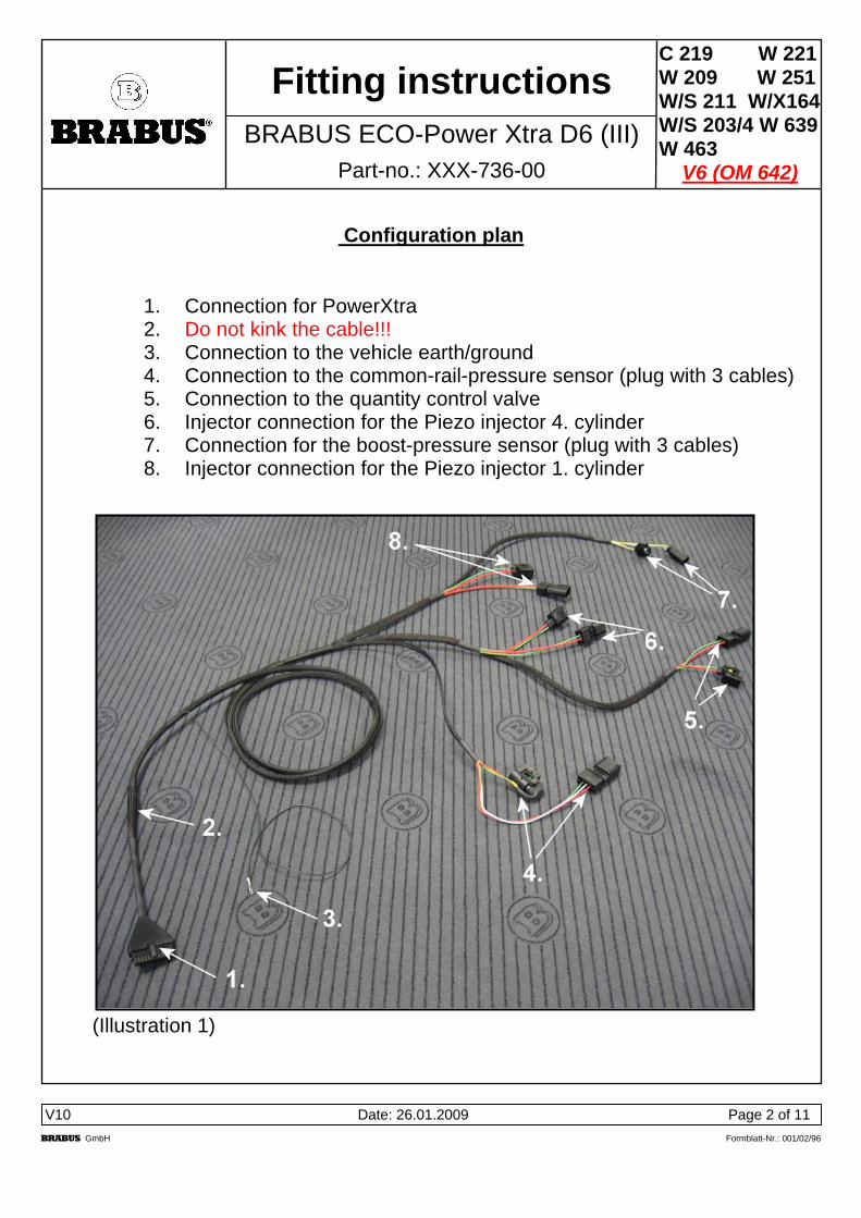
1. Connection for PowerXtra 2. Do not kink the cable!!! 3. Connection to the vehicle earth/ground 4. Connection to the common-rail-pressure sensor (plug with 3 cables) 5. Connection to the quantity control valve 6. Injector connection for the Piezo injector 4. cylinder 7. Connection for the boost-pressure sensor (plug with 3 cables) 8. Injector connection for the Piezo injector 1. cylinder

(Illustration 1)

V10 Date: 26.01.2009 Page 3 of 11 BRABUS GmbH Formblatt-Nr.: 001/02/96

C 219 W 221W 209 W 251W/S 211 W/X164W/S 203/4 W 639W 463

V6 (OM 642) Part-no.: XXX-736-00 BRABUS ECO-Power Xtra D6 (III)

Fitting instructions

Cable plan

(Illustration 2)

Assembly at the quantity control valve (power supply)

1. Pull off the original plug the quantity control valve and connect it to the BRABUS adapter (plug 5; illustration1/2).

2. Attach the adapter to the wiring harness of the quantity control valve by using a

cable strap.

3. Connect the BRABUS plug to the quantity control valve.

4. Take care that the wiring is protected against damages and double check the correct fitting of the connectors.

V10 Date: 26.01.2009 Page 4 of 11 BRABUS GmbH Formblatt-Nr.: 001/02/96

C 219 W 221W 209 W 251W/S 211 W/X164W/S 203/4 W 639W 463

V6 (OM 642) Part-no.: XXX-736-00 BRABUS ECO-Power Xtra D6 (III)

Fitting instructions

Assembly at the boost-pressure sensor 5. Pull off the original plug from the boost-pressure sensor and connect it to the

BRABUS adapter (plug 7; illustration 3).

6. Attach the adapter to the wiring harness of the boost-pressure sensor by using a cable strap.

7. Connect the BRABUS plug to the boost-pressure sensor.

8. After assembly take care that the wiring and plugs do not get in contact to the

fan.

(Illustration 3)

V10 Date: 26.01.2009 Page 5 of 11 BRABUS GmbH Formblatt-Nr.: 001/02/96

C 219 W 221W 209 W 251W/S 211 W/X164W/S 203/4 W 639W 463

V6 (OM 642) Part-no.: XXX-736-00 BRABUS ECO-Power Xtra D6 (III)

Fitting instructions

Assembly at the injectors

1. Pull off the original plugs of from the injectors of the first (plug 8; illustration 4) and fourth cylinder (plug 6; illustration 5) and connect it to the BRABUS adapter.

Attach the adapter and the wiring at the rail by using a cable strap.

2. Connect the BRABUS plugs to the injectors.

3. Take care that the wiring is protected against damages and check the correct

fitting of the connectors.

(Illustration 4) (Illustration 5)

V10 Date: 26.01.2009 Page 6 of 11 BRABUS GmbH Formblatt-Nr.: 001/02/96

C 219 W 221W 209 W 251W/S 211 W/X164W/S 203/4 W 639W 463

V6 (OM 642) Part-no.: XXX-736-00 BRABUS ECO-Power Xtra D6 (III)

Fitting instructions

Assembly at the common-rail-pressure sensor 1. Pull off the original plug from the rail-pressure sensor and connect it to the

BRABUS adapter plug (plug 4; illustration 6).

2. Attach the adapter plug with a cable strap to protect it against temperature of the turbocharger and the exhaust system.

3. Take care that the wiring is lead loose and not squeezed.

(Illustration 6)

V10 Date: 26.01.2009 Page 7 of 11 BRABUS GmbH Formblatt-Nr.: 001/02/96

C 219 W 221W 209 W 251W/S 211 W/X164W/S 203/4 W 639W 463

V6 (OM 642) Part-no.: XXX-736-00 BRABUS ECO-Power Xtra D6 (III)

Fitting instructions

Fitting the ECU

1. Attach the clip of the PowerXtra control unit at a suitable place. 2. We recommend to attach the control unit in the module box.

3. For W 204 and 211/ C219 Facelift cars, see page 9.

4. For W 463 cars see page 11.

5. Connect the wiring harness to the control unit and pay attention that the

connection is not under tension load.

Attention! Do not kink the red marked area of the cable!!! (see illustration 7)

6. Clip in the control unit. (Illustration 7)

7. Connect the black earth cable to the vehicle earth.

8. Finally check all connections and make a test drive.

V10 Date: 26.01.2009 Page 8 of 11 BRABUS GmbH Formblatt-Nr.: 001/02/96

C 219 W 221W 209 W 251W/S 211 W/X164W/S 203/4 W 639W 463

V6 (OM 642) Part-no.: XXX-736-00 BRABUS ECO-Power Xtra D6 (III)

Fitting instructions

Only for Viano W 639

Because it is a difficult matter to reach the rear end of the V6 engine it is necessary to pay special attention to the rail pressure sensor. Therefore we recommend removing all covers of the engine as shown in the picture above. The removal is made, according to the DC fitting instructions. The oil filler neck can be removed by turning left after the retaining screw has been removed.

V10 Date: 26.01.2009 Page 9 of 11 BRABUS GmbH Formblatt-Nr.: 001/02/96

C 219 W 221W 209 W 251W/S 211 W/X164W/S 203/4 W 639W 463

V6 (OM 642) Part-no.: XXX-736-00 BRABUS ECO-Power Xtra D6 (III)

Fitting instructions

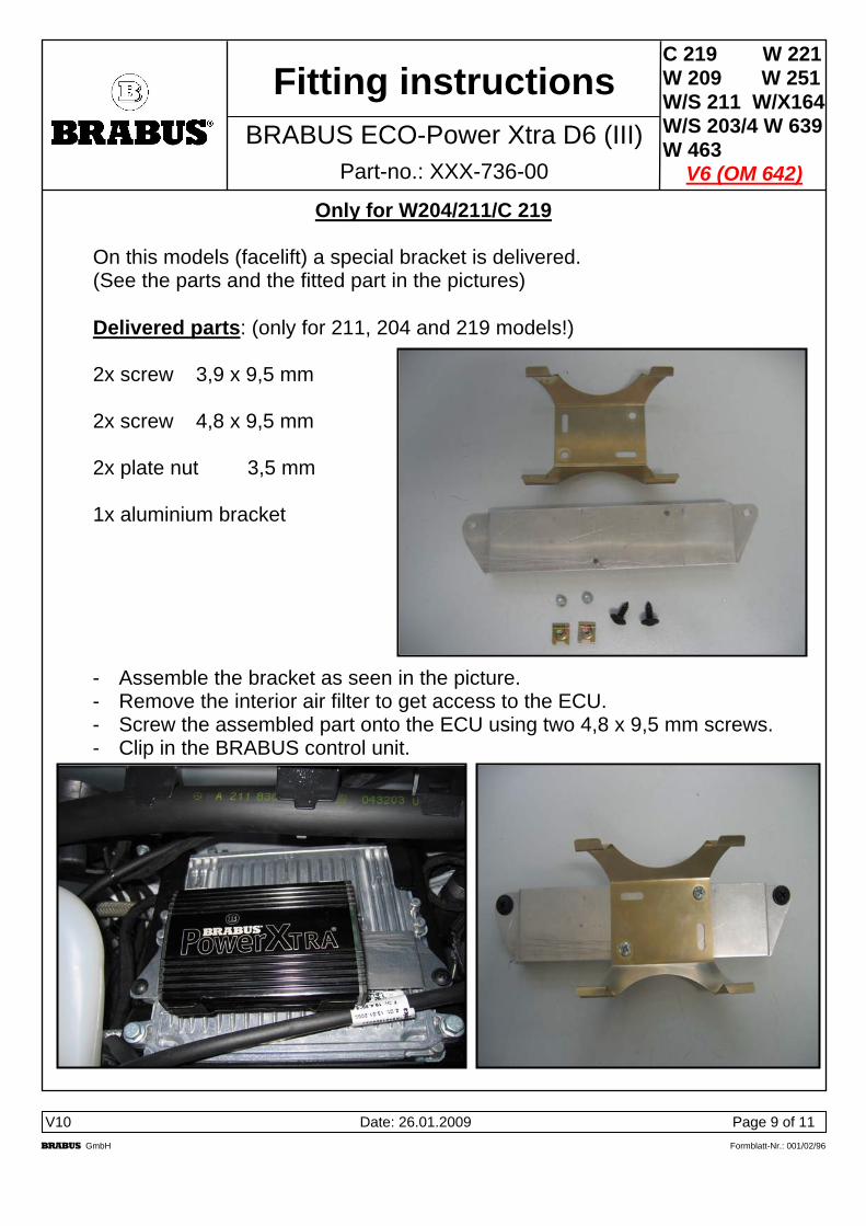
Only for W204/211/C 219 On this models (facelift) a special bracket is delivered. (See the parts and the fitted part in the pictures) Delivered parts: (only for 211, 204 and 219 models!) 2x screw 3,9 x 9,5 mm 2x screw 4,8 x 9,5 mm 2x plate nut 3,5 mm 1x aluminium bracket

- Assemble the bracket as seen in the picture. - Remove the interior air filter to get access to the ECU. - Screw the assembled part onto the ECU using two 4,8 x 9,5 mm screws. - Clip in the BRABUS control unit.

V10 Date: 26.01.2009 Page 10 of 11 BRABUS GmbH Formblatt-Nr.: 001/02/96

C 219 W 221W 209 W 251W/S 211 W/X164W/S 203/4 W 639W 463

V6 (OM 642) Part-no.: XXX-736-00 BRABUS ECO-Power Xtra D6 (III)

Fitting instructions

G-Model W 463 Please pay attention to the slight different set up of the wiring. The Power Xtra box gets attached into the delivered Overbox. (see next page)

V10 Date: 26.01.2009 Page 11 of 11 BRABUS GmbH Formblatt-Nr.: 001/02/96

C 219 W 221W 209 W 251W/S 211 W/X164W/S 203/4 W 639W 463

V6 (OM 642) Part-no.: XXX-736-00 BRABUS ECO-Power Xtra D6 (III)

Fitting instructions

The assembly of the kit is the same as above, but the ECU gets attached in an

overbox. See the picture for the assembly and follow the numbered steps. Choose a suitable place for the installation. Clean the bonding surface with the delivered cleaning cloth. Remove the protective film and press the box firmly onto the cleaned surface.

           Kabelsatz D6 000‐736‐05‐T3     Wiring harness D6 000‐736‐05‐T3   


Wichtiger Hinweis/ important hint

Der Kabelsatz für die Leistungskits D6-III ist mit einer Zusatzfunktion ausgestattet, die einen zusätzlichen Temperaturfühleranschluss ermöglicht.

Dieser zusätzliche Temperaturfühler wird nur bei Fahrzeugen der Baureihen

W/ V221 S320/ 350CDI

W/ X164 (ML/ GL 350 CDI mit Euro 5-Abgasnorm)

verwendet.

Bei allen anderen Fahrzeugen bleibt diese Steckverbindung zusammengesteckt, der Temperaturfühleranschluss wird nicht benötigt!

The wiring harness, article-no. 002-736-05-T3 is equipped with a special temperature-sensor connection. This connection is only used when the performance-kit gets attached to following cars:

W/ V221 S320/ 350CDI

W/ X164 (ML/ GL350 CDI/ Euro 5).

At all other cars this connection remains connected, the temperature-sensor connector is not used.


Recommended