Page 6–2 DURApulse GS20 & GS20X AC Drive User Manual – 1st Edition, Rev C
Chapter 6: Maintenance and Troubleshooting
Maintenance and InspectionsModern AC drives are based on solid state electronics technology, including ICs, resistors, capacitors, transistors, cooling fans, relays, etc. These components have a limited life under normal operation. Preventive maintenance is required to operate the GS20(X) drive in its optimal condition, and to ensure a long life. We recommend that a qualified technician perform a regular inspection of the GS20(X) drive. Some items should be checked once a month, and some items should be checked yearly.
NOTE: All inspections should be accomplished with Safety in mind with due and required caution. Some of these Inspection items may require the Drive to be powered down, while others may require power to be applied. Proper safety precautions including the use of PPE are/may be required. Please review cautionary statements in each section
Monthly InspectionCheck the following items at least once a month.
1) Make sure the motors are operating as expected�2) Make sure the drive installation environment is normal�3) Make sure the enclosure and drive cooling systems are operating as expected�4) Check for irregular vibrations or sounds during operation�5) Make sure the motors are not overheating during operation�
6) Check the input voltage to the GS20(X) drive and make sure the voltage is within the operating range� Check the voltage with a voltmeter�
Annual InspectionCheck the following items once annually.
1) Check the torque of the GS20(X) power and control terminal screws and tighten if necessary� They may loosen due to vibration or changing temperatures�
2) Make sure the conductors and insulators are not corroded or damaged�3) Check the resistance of cable insulation with a megohmmeter�4) Clean off any dust and dirt with a vacuum cleaner� Pay special attention to cleaning the
ventilation ports and PCBs� Always keep these areas clean� Accumulation of dust and dirt in these areas can cause unforeseen failures�
5) Recharge the capacitors of any drive that is in storage or is otherwise unused�
Chapter 6: Maintenance and Troubleshooting
Page 6–3DURApulse GS20 & GS20X AC Drive User Manual – 1st Edition, Rev C
Recharge Capacitors (for drives not in service)Recharge the DC link before using any drive that has not been operated within a year:
1) Disconnect the motor from the drive�2) Apply input power to the drive for 2 hours�
If the drive is stored or is otherwise unused for more than a year, the drive’s internal DC link capacitors should be recharged before use. Otherwise, the capacitors may be damaged when the drive starts to operate. We recommend recharging the capacitors of any unused drive at least once per year.
CAUTION
☑ Wait 5 seconds after a fault has been cleared before performing reset via keypad or input terminal.
☑ When the power is off after 5 minutes for ≤ 30hp models and 10 minutes for ≥ 40hp models, please confirm that the capacitors have fully discharged by measuring the voltage between + and -. The voltage between + and - should be less than 25VDC.
☑ Only qualified personnel can install, wire and maintain drives. Please take off any metal objects, such as watches and rings, before operation. And only insulated tools are allowed.
☑ Never reassemble internal components or wiring.☑ Make sure that installation environment complies with regulations
without abnormal noise, vibration and smell.
Page 6–4 DURApulse GS20 & GS20X AC Drive User Manual – 1st Edition, Rev C
Chapter 6: Maintenance and Troubleshooting
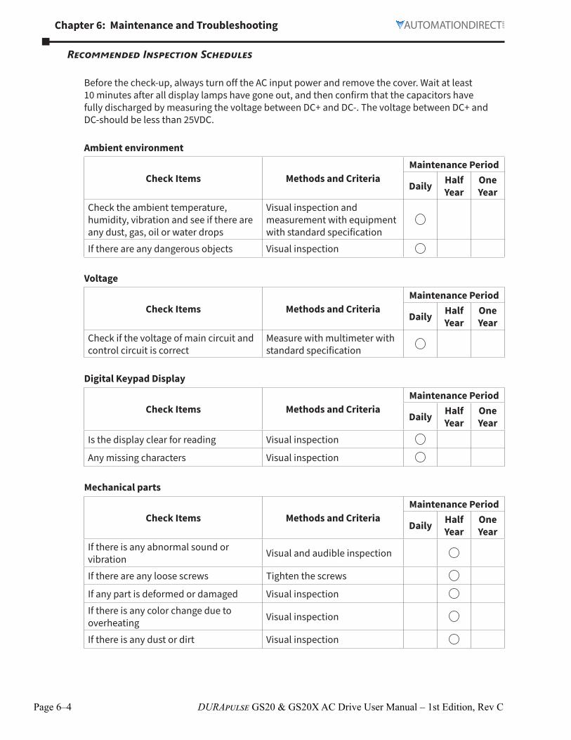
Recommended Inspection Schedules
Before the check-up, always turn off the AC input power and remove the cover. Wait at least 10 minutes after all display lamps have gone out, and then confirm that the capacitors have fully discharged by measuring the voltage between DC+ and DC-. The voltage between DC+ and DC-should be less than 25VDC.
Ambient environment
Check Items Methods and CriteriaMaintenance Period
Daily Half Year
One Year
Check the ambient temperature, humidity, vibration and see if there are any dust, gas, oil or water drops
Visual inspection and measurement with equipment with standard specification
If there are any dangerous objects Visual inspection
Voltage
Check Items Methods and CriteriaMaintenance Period
Daily Half Year
One Year
Check if the voltage of main circuit and control circuit is correct
Measure with multimeter with standard specification
Digital Keypad Display
Check Items Methods and CriteriaMaintenance Period
Daily Half Year
One Year
Is the display clear for reading Visual inspection
Any missing characters Visual inspection
Mechanical parts
Check Items Methods and CriteriaMaintenance Period
Daily Half Year
One Year
If there is any abnormal sound or vibration Visual and audible inspection
If there are any loose screws Tighten the screws
If any part is deformed or damaged Visual inspectionIf there is any color change due to overheating Visual inspection
If there is any dust or dirt Visual inspection
Chapter 6: Maintenance and Troubleshooting
Page 6–5DURApulse GS20 & GS20X AC Drive User Manual – 1st Edition, Rev C
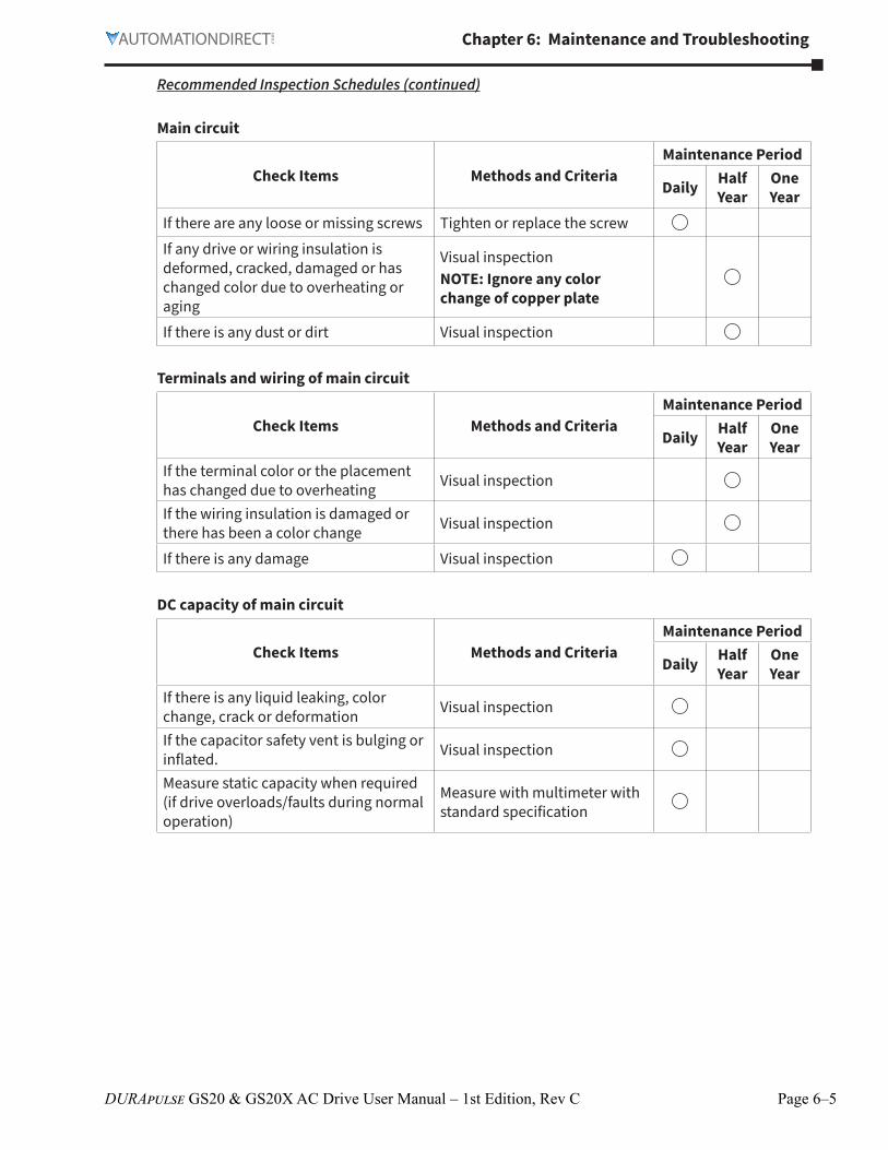
Recommended Inspection Schedules (continued)
Main circuit
Check Items Methods and CriteriaMaintenance Period
Daily Half Year
One Year
If there are any loose or missing screws Tighten or replace the screwIf any drive or wiring insulation is deformed, cracked, damaged or has changed color due to overheating or aging
Visual inspectionNOTE: Ignore any color change of copper plate
If there is any dust or dirt Visual inspection
Terminals and wiring of main circuit
Check Items Methods and CriteriaMaintenance Period
Daily Half Year
One Year
If the terminal color or the placement has changed due to overheating Visual inspection
If the wiring insulation is damaged or there has been a color change Visual inspection
If there is any damage Visual inspection
DC capacity of main circuit
Check Items Methods and CriteriaMaintenance Period
Daily Half Year
One Year
If there is any liquid leaking, color change, crack or deformation Visual inspection
If the capacitor safety vent is bulging or inflated. Visual inspection
Measure static capacity when required (if drive overloads/faults during normal operation)
Measure with multimeter with standard specification
Page 6–6 DURApulse GS20 & GS20X AC Drive User Manual – 1st Edition, Rev C
Chapter 6: Maintenance and Troubleshooting
Recommended Inspection Schedules (continued)
Resistor of main circuit
Check Items Methods and CriteriaMaintenance Period
Daily Half Year
One Year
If there is any peculiar smell or insulation cracks due to overheating Visual inspection, smell
If there is any disconnection or discoloration Visual inspection
If the connection is damaged Measure with a multimeter with standard specifications
Transformer and reactor of main circuit
Check Items Methods and CriteriaMaintenance Period
Daily Half Year
One Year
If there is any abnormal vibration or peculiar smell
Visual, audible inspection and smell
Magnetic contactor and relay of main circuit
Check Items Methods and CriteriaMaintenance Period
Daily Half Year
One Year
If there are any loose screws Visual and audible inspection
If the contact works correctly Visual inspection
Printed circuit board and connector of main circuit
Check Items Methods and CriteriaMaintenance Period
Daily Half Year
One Year
If there are any loose screws and connectors
Tighten the screws and press the connectors firmly in place
If there is any peculiar smell and/or color change Visual and smell inspection
If there is any crack, damage, deformation or corrosion Visual inspection
If there is any liquid leakage or deformation in capacity Visual inspection
Chapter 6: Maintenance and Troubleshooting
Page 6–7DURApulse GS20 & GS20X AC Drive User Manual – 1st Edition, Rev C
Recommended Inspection Schedules (continued)
Cooling fan of cooling system
Check Items Methods and CriteriaMaintenance Period
Daily Half Year
One Year
If there is any abnormal sound or vibration
Visual, audible inspection and turn the fan with hand (turn off the power before operation) to see if it rotates smoothly
If there is any loose screw Tighten the screwIf there is any color change due to overheating Change the fan
Ventilation channel of cooling system
Check Items Methods and CriteriaMaintenance Period
Daily Half Year
One Year
If there is any obstruction in the heat sink, air intake or air outlet Visual inspection
Please use a clean lint free cloth for cleaning and use a dust cleaner to remove dust when necessary.
Page 6–8 DURApulse GS20 & GS20X AC Drive User Manual – 1st Edition, Rev C
Chapter 6: Maintenance and Troubleshooting
TroubleshootingWarning Codes
The GS20(X) drive has a comprehensive diagnostic system that includes several different warning codes. The most common warning codes can be read on the digital keypad display. For communication errors, “Upper unit” is referring to the Master controller of the serial network. Always ensure the communication settings of the drive (P09.01 and P09.04) match those of the master controller and network.
Warning CodesDisplay on
GS20(X) Keypad
ID No. Warning Name and Description Action and Reset Corrective Action
n/a 0 No error n/a n/a n/a
CE1 1
Communication error 1 (CE1)
RS-485 Modbus illegal function code�
Action Level When the function code is 03, 06, 10, and 63
1) Check if the communication command is correct
2) Verify the wiring and grounding of the communication circuit� Separate the communication circuit from the main circuit, or wire in 90 degree for effective anti-interference performance�
3) Check if the setting for P09�04 is the same as the setting for the upper unit�
4) Check the cable and replace it if necessary�
Action Time Immediately actWarning setting parameter N/A
Reset method
“Warning” occurs when P09�02=0 and the motor drive keeps running� The drive resets automatically when receiving the correct function code�
Reset condition Immediately resetRecord N/A
CE2 2
Communication error 2 (CE2)
RS-485 Modbus illegal data address
Action Level When the input data address is incorrect
1) Check if the communication command is correct�
2) Verify the wiring and grounding of the communication circuit� Separate the communication circuit from the main circuit, or wire in 90 degree for effective anti-interference performance�
3) Check if the setting for P09�04 is the same as the setting for the upper unit�
4) Check the cable and replace it if necessary�
Action Time Immediately actWarning setting parameter N/A
Reset method
“Warning” occurs when P09�02=0 and the motor drive keeps running� The drive resets automatically when receiving the correct data address�
Reset condition Immediately reset
Record N/A
CE3 3
Communication error 3 (CE3)
RS-485 Modbus illegal data value
Action Level When the length of communication data is too long
1) Check if the communication command is correct�
2) Verify the wiring and grounding of the communication circuit� Separate the communication circuit from the main circuit, or wire in 90 degree for effective anti-interference performance�
3) Check if the setting for P09�04 is the same as the setting for the upper unit�
4) Check the cable and replace it if necessary�
Action Time Immediately actWarning setting parameter N/A
Reset method
“Warning” occurs when P09�02=0 and the motor drive keeps running� The drive resets automatically when receiving the correct communication data value�
Reset condition Immediately resetRecord N/A
(continued next page)
Chapter 6: Maintenance and Troubleshooting
Page 6–9DURApulse GS20 & GS20X AC Drive User Manual – 1st Edition, Rev C
Warning Codes (continued)Display on
GS20(X) Keypad
ID No. Warning Name and Description Action and Reset Corrective Action
CE4 4
Communication error 4 (CE4)
RS-485 Modbus data is written to read-only address
Action Level When the data is written to read-only address
1) Check if the communication command is correct
2) Verify the wiring and grounding of the communication circuit� Separate the communication circuit from the main circuit, or wire in 90 degree for effective anti-interference performance�
3) Check if the setting for P09�04 is the same as the setting for the upper unit�
4) Check the cable and replace it if necessary�
Action Time Immediately actWarning setting parameter N/A
Reset method
“Warning” occurs when P09�02=0 and the motor drive keeps running� The drive resets automatically when receiving the correct written address of communication data�
Reset condition Immediately resetRecord N/A
CE10 5
Communication error 10 (CE10)
RS-485 Modbus transmission time-out
Action Level
When the communication time exceeds the detection time of P09�03 communication time-out
1) Check if the upper unit transmits the communication command within the setting time for P09�03�
2) Verify the wiring and grounding of the communication circuit� It is recommended to separate the communication circuit from the main circuit, or wire in 90 degree for effective anti-interference performance�
3) Check if the setting for P09�04 is the same as the setting for the upper unit�
4) Check the cable and replace it if necessary�
Action Time P09�03Warning setting parameter N/A
Reset method
“Warning” occurs when P09�02=0 and the motor drive keeps running� The drive resets automatically when receiving the next communication packet�
Reset condition Immediately reset
Record N/A
SE1 7
Save error 1 (SE1)
Keypad COPY error 1: Keypad copy time-out
Action Level
“SE1” warning occurs when the GS4-KPD optional keypad does not transmit the COPY command to the drive, and does not transmit any data to the drive again in 10 ms at the time you copy the parameters to the drive�
SE1: The causes of error are mostly communication problems between the keypad and control board� Potential causes include communication signal interference and the unacceptable communication command to the Slave�Check if the error occurs randomly, or only occurs when copying certain parameters (the error displays on the upper right corner of the copy page)� If you cannot clear the error, please contact AutomationDirect Technical Support�
“SE2” warning occurs when writing the parameters incorrectly at the time you copy parameters to the drive� For example, you copy the new firmware version with added parameters to the drive with old firmware version�
SE2: In this stage, the copied data has been transmitted to the Slave�The Slave compares and processes the copied data, and then saves the data to the Data ROM� During the process, the data error (should be attribution error) may occur, or the data cannot be saved to EEPROM� At this time, the warning occurs�Check the status of Data ROM and remove the error causes first�If you cannot clear the error, please contact AutomationDirect Technical Support�
Page 6–10 DURApulse GS20 & GS20X AC Drive User Manual – 1st Edition, Rev C
Chapter 6: Maintenance and Troubleshooting
Warning Codes (continued)Display on
GS20(X) Keypad
ID No. Warning Name and Description Action and Reset Corrective Action
oHI 9
IGBT over-heating warning (oH1)
The AC motor drive detects IGBT overheating and exceeds the protection level of oH1 warning� (When P06�15 is higher than the IGBT overheating protection level, the drive shows oH1 error without displaying oH1 warning�)
Action Level P06�15 1) Check the ambient temperature�2) Regularly inspect the ventilation hole
of the control cabinet�3) Change the installed location if there
are heating objects, such as braking resistors, in the surroundings�
4) Install/add cooling fan or air conditioner to lower the temperature inside the cabinet�
5) Check for and remove obstructions or replace the cooling fan�
6) Increase ventilation space of the drive�
7) Decrease loading�8) Decrease the carrier wave�9) Replace the drive with higher
capacity model�
Action Time“oH1” warning occurs when IGBT temperature is higher than P06�15 setting value�
Warning setting parameter N/A
Reset method Auto-reset
Reset conditionThe drive auto-resets when IGBT temperature is lower than oH1 warning level minus (–) 5°C
Record N/A
PID 11
PID feedback error (PID)
PID feedback loss (warning for analog feedback signal; works only when PID enables)
Action LevelWhen the analog input is lower than 4 mA (only detects analog input 4–20 mA)
1) Check the PID feedback wiring and tighten the terminals�
2) Replace the cable�3) Replace the feedback device�4) If the PID error still occurs after
checking all the wiring, contact AutomationDirect Technical Support�
Action Time P08�08
Warning setting parameter
P08�09 setting is:0: Warn and continue operation1: Fault and ramp to stop2: Fault and coast to stop3: Warn and operate at last frequency
Reset method
1) Auto: “Warning” occurs when P08.09=0 or 3. The “Warning” automatically clears when the feedback signal is larger than 4 mA.
2) Manual: “Error” occurs when P08.09=1 or 2. You must reset manually.
Reset condition Immediately reset
Record
Records when P08�09=1 or 2 (“Error”)�Does not record when P08�09=3 (“Warning”)�
(continued next page)
Chapter 6: Maintenance and Troubleshooting
Page 6–11DURApulse GS20 & GS20X AC Drive User Manual – 1st Edition, Rev C
Warning Codes (continued)Display on
GS20(X) Keypad
ID No. Warning Name and Description Action and Reset Corrective Action
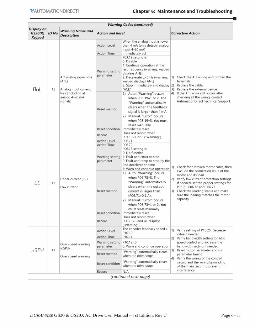
AnL 12
AI2 analog signal loss (AnL)
Analog input current loss (including all analog 4–20 mA signals)
Action LevelWhen the analog input is lower than 4 mA (only detects analog input 4–20 mA)
1) Check the AI2 wiring and tighten the terminals�
2) Replace the cable�3) Replace the external device�4) If the AnL error still occurs after
checking all the wiring, contact AutomationDirect Technical Support�
Action Time Immediately act
Warning setting parameter
P03�19 setting is:0: Disable1: Continue operation at the last frequency (warning, keypad displays ANL)2: Decelerate to 0 Hz (warning, keypad displays ANL)3: Stop immediately and display “ACE”
Reset method
1) Auto: “Warning” occurs when P03.19=1 or 2. The “Warning” automatically clears when the feedback signal is larger than 4 mA.
2) Manual: “Error” occurs when P03.19=3. You must reset manually.
Reset condition Immediately reset
Record Does not record when P03�19=1 or 2 (“Warning”)�
uC 13Under current (uC)
Low current
Action Level P06�71
1) Check for a broken motor cable, then exclude the connection issue of the motor and its load�
2) Verify low current protection settings� If needed, set the proper settings for P06�71, P06�72 and P06�73�
3) Check the loading status and make sure the loading matches the motor capacity�
Action Time P06�72
Warning setting parameter
P06�73 setting is:0: No function1: Fault and coast to stop2: Fault and ramp to stop by the 2nd deceleration time3: Warn and continue operation
Reset method
1) Auto: “Warning” occurs when P06.73=3. The “Warning” automatically clears when the output current is larger than (P06.71+0.1 A).
2) Manual: “Error” occurs when P06.73=1 or 2. You must reset manually.
Reset condition Immediately reset
RecordDoes not record when P06�73=3 and uC displays (“Warning”)�
oSPD 17
Over speed warning (oSPd)
Over speed warning
Action Level The encoder feedback speed > P10�10
1) Verify setting of P10�25� Decrease value if needed�
2) Verify bandwidth setting for ASR speed control and increase the bandwidth setting if needed�
3) Reset motor parameter and run parameter tuning�
4) Verify the wiring of the control circuit, and the wiring/grounding of the main circuit to prevent interference�
Action Time P10�11Warning setting parameter
P10�12=00: Warn and continue operation
Reset method “Warning” automatically clears when the drive stops
Reset condition “Warning” automatically clears when the drive stops
Record N/A(continued next page)
Page 6–12 DURApulse GS20 & GS20X AC Drive User Manual – 1st Edition, Rev C
Chapter 6: Maintenance and Troubleshooting
Warning Codes (continued)Display on
GS20(X) Keypad
ID No. Warning Name and Description Action and Reset Corrective Action
dAvE 18
Deviation Warning (dAvE)
Over speed deviation warning
Action Level P10�13 1) Verify parameter setting for slip error and reset value for P10�13 and P10�14 if needed�
2) Reset ASR parameters and set proper accel�/ decel� time�
3) Verify motor status and remove any causes if the motor is locked�
4) Check status of the mechanical brake and verify the action timing of the system if the brake is not released�
5) Verify torque limit and adjust parameters P06�12 and P11�17-P11�20 as needed�
6) Verify the wiring of the control circuit, and the wiring/grounding of the main circuit to prevent interference�
Action Time P10�14
Warning setting parameter
P10�15 Encoder Stall and Slip Error Action =00: Warn and continue operation
Reset method “Warning” automatically clears when the drive stops
Reset condition After the drive stops
Record N/A
PHL 19
Phase loss (PHL)
Input phase loss warning
Action Level One of the phases outputs less than P06�47
1) Verify the wiring of the main circuit�2) Verify a single-phase power input
is not being used on a three-phase model� Use the model with voltage that matches the power�
3) If the power of main circuit works well, check if the MC of the main circuit is broken� Cycle the power after verifying the power is normal� If PHL still occurs, contact AutomationDirect Technical Support�
4) Tighten the terminal screws with the torque listed in the user manual�
5) Verify the input cable is not broken� Make sure the wiring is correct�Replace the broken part of the cable if needed�
6) Verify the three-phase power is not unbalanced�
Action Time P06�46
Warning setting parameter
P06�45 Output Phase Loss Detection Action (OPHL) =00: Warn and continue operation
Reset method “Warning” automatically clears when the drive stops
Reset condition After the drive stops
Record N/A
(continued next page)
Chapter 6: Maintenance and Troubleshooting
Page 6–13DURApulse GS20 & GS20X AC Drive User Manual – 1st Edition, Rev C
Warning Codes (continued)Display on
GS20(X) Keypad
ID No. Warning Name and Description Action and Reset Corrective Action
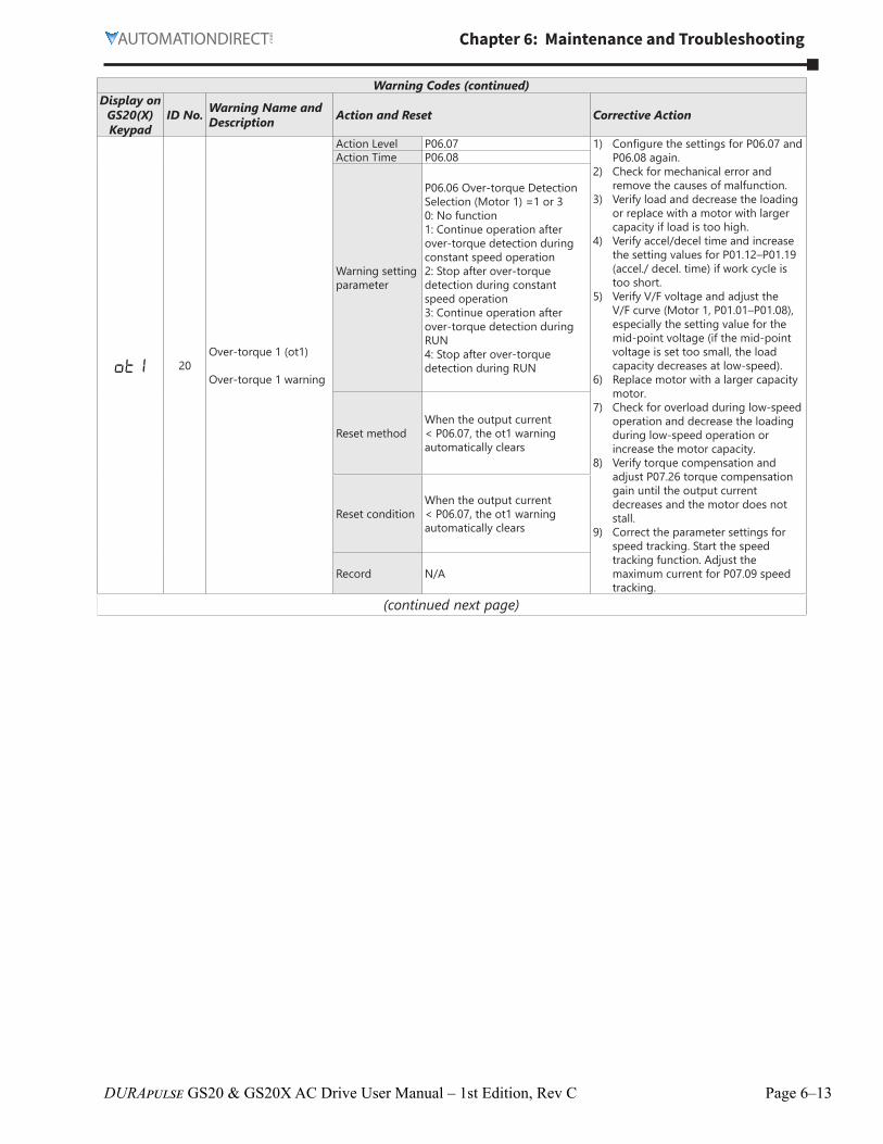
ot1 20Over-torque 1 (ot1)
Over-torque 1 warning
Action Level P06�07 1) Configure the settings for P06�07 and P06�08 again�
2) Check for mechanical error and remove the causes of malfunction�
3) Verify load and decrease the loading or replace with a motor with larger capacity if load is too high�
4) Verify accel/decel time and increase the setting values for P01�12–P01�19 (accel�/ decel� time) if work cycle is too short�
5) Verify V/F voltage and adjust the V/F curve (Motor 1, P01�01–P01�08), especially the setting value for the mid-point voltage (if the mid-point voltage is set too small, the load capacity decreases at low-speed)�
6) Replace motor with a larger capacity motor�
7) Check for overload during low-speed operation and decrease the loading during low-speed operation or increase the motor capacity�
8) Verify torque compensation and adjust P07�26 torque compensation gain until the output current decreases and the motor does not stall�
9) Correct the parameter settings for speed tracking� Start the speed tracking function� Adjust the maximum current for P07�09 speed tracking�
Action Time P06�08
Warning setting parameter
P06�06 Over-torque Detection Selection (Motor 1) =1 or 30: No function1: Continue operation after over-torque detection during constant speed operation2: Stop after over-torque detection during constant speed operation3: Continue operation after over-torque detection during RUN4: Stop after over-torque detection during RUN
Reset methodWhen the output current < P06�07, the ot1 warning automatically clears
Reset conditionWhen the output current < P06�07, the ot1 warning automatically clears
Record N/A
(continued next page)
Page 6–14 DURApulse GS20 & GS20X AC Drive User Manual – 1st Edition, Rev C
Chapter 6: Maintenance and Troubleshooting
Warning Codes (continued)Display on
GS20(X) Keypad
ID No. Warning Name and Description Action and Reset Corrective Action
ot2 21Over-torque (ot2)
Over-torque 2 warning
Action Level P06�10 1) Configure the settings for P06�10 and P06�11 again�
2) Check for mechanical error and remove the causes of malfunction�
3) Verify load and decrease the loading or replace with a motor with larger capacity if load is too high�
4) Verify accel/decel time and increase the setting values for P01�12–P01�19 (accel�/ decel� time) if work cycle is too short�
5) Verify V/F voltage and adjust the V/F curve (Motor 2, P01�35–P01�42), especially the setting value for the mid-point voltage (if the mid-point voltage is set too small, the load capacity decreases at low-speed)�
6) Replace motor with a larger capacity motor�
7) Check for overload during low-speed operation and decrease the loading during low-speed operation or increase the motor capacity�
8) Verify torque compensation and adjust P07�71 torque compensation gain until the output current decreases and the motor does not stall�
9) Correct the parameter settings for speed tracking� Start the speed tracking function� Adjust the maximum current for P07�09 speed tracking�
Action Time P06�11
Warning setting parameter
P06�09 Over-torque Detection Selection (Motor 2) =1 or 30: No function1: Continue operation after over-torque detection during constant speed operation2: Stop after over-torque detection during constant speed operation3: Continue operation after over-torque detection during RUN4: Stop after over-torque detection during RUN
Reset methodWhen the output current < P06�10, the ot2 warning automatically clears
Reset conditionWhen the output current < P06�10, the ot2 warning automatically clears
Record N/A
(continued next page)
Chapter 6: Maintenance and Troubleshooting
Page 6–15DURApulse GS20 & GS20X AC Drive User Manual – 1st Edition, Rev C
Warning Codes (continued)Display on
GS20(X) Keypad
ID No. Warning Name and Description Action and Reset Corrective Action
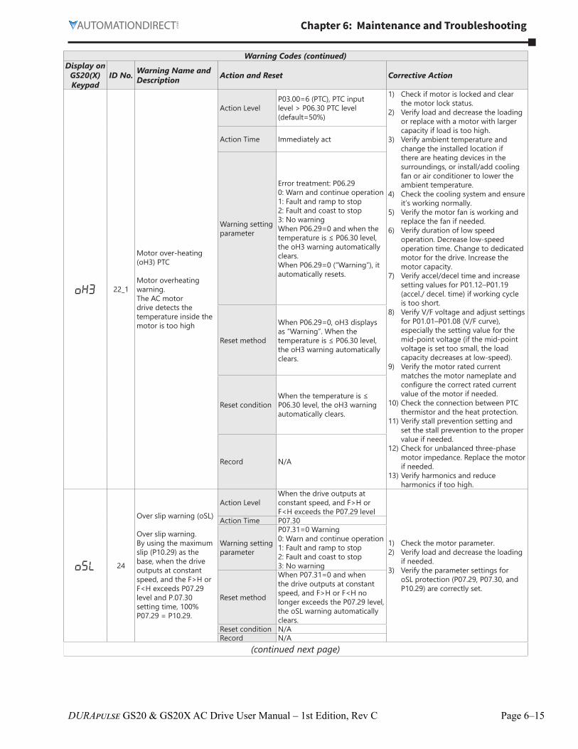
oH3 22_1
Motor over-heating (oH3) PTC
Motor overheating warning�The AC motor drive detects the temperature inside the motor is too high
1) Check if motor is locked and clear the motor lock status�
2) Verify load and decrease the loading or replace with a motor with larger capacity if load is too high�
3) Verify ambient temperature and change the installed location if there are heating devices in the surroundings, or install/add cooling fan or air conditioner to lower the ambient temperature�
4) Check the cooling system and ensure it’s working normally�
5) Verify the motor fan is working and replace the fan if needed�
6) Verify duration of low speed operation� Decrease low-speed operation time� Change to dedicated motor for the drive� Increase the motor capacity�
7) Verify accel/decel time and increase setting values for P01�12–P01�19 (accel�/ decel� time) if working cycle is too short�
8) Verify V/F voltage and adjust settings for P01�01–P01�08 (V/F curve), especially the setting value for the mid-point voltage (if the mid-point voltage is set too small, the load capacity decreases at low-speed)�
9) Verify the motor rated current matches the motor nameplate and configure the correct rated current value of the motor if needed�
10) Check the connection between PTC thermistor and the heat protection�
11) Verify stall prevention setting and set the stall prevention to the proper value if needed�
12) Check for unbalanced three-phase motor impedance� Replace the motor if needed�
13) Verify harmonics and reduce harmonics if too high�
Action Time Immediately act
Warning setting parameter
Error treatment: P06�290: Warn and continue operation1: Fault and ramp to stop2: Fault and coast to stop3: No warningWhen P06�29=0 and when the temperature is ≤ P06�30 level, the oH3 warning automatically clears�When P06�29=0 (“Warning”), it automatically resets�
Reset method
When P06�29=0, oH3 displays as “Warning”� When the temperature is ≤ P06�30 level, the oH3 warning automatically clears�
Reset conditionWhen the temperature is ≤ P06�30 level, the oH3 warning automatically clears�
Record N/A
oSL 24
Over slip warning (oSL)
Over slip warning�By using the maximum slip (P10�29) as the base, when the drive outputs at constant speed, and the F>H or F<H exceeds P07�29 level and P�07�30 setting time, 100% P07�29 = P10�29�
Action LevelWhen the drive outputs at constant speed, and F>H or F<H exceeds the P07�29 level
1) Check the motor parameter�2) Verify load and decrease the loading
if needed�3) Verify the parameter settings for
oSL protection (P07�29, P07�30, and P10�29) are correctly set�
Action Time P07�30
Warning setting parameter
P07�31=0 Warning0: Warn and continue operation1: Fault and ramp to stop2: Fault and coast to stop3: No warning
Reset method
When P07�31=0 and when the drive outputs at constant speed, and F>H or F<H no longer exceeds the P07�29 level, the oSL warning automatically clears�
Reset condition N/ARecord N/A
(continued next page)
Page 6–16 DURApulse GS20 & GS20X AC Drive User Manual – 1st Edition, Rev C
Chapter 6: Maintenance and Troubleshooting
Warning Codes (continued)Display on
GS20(X) Keypad
ID No. Warning Name and Description Action and Reset Corrective Action
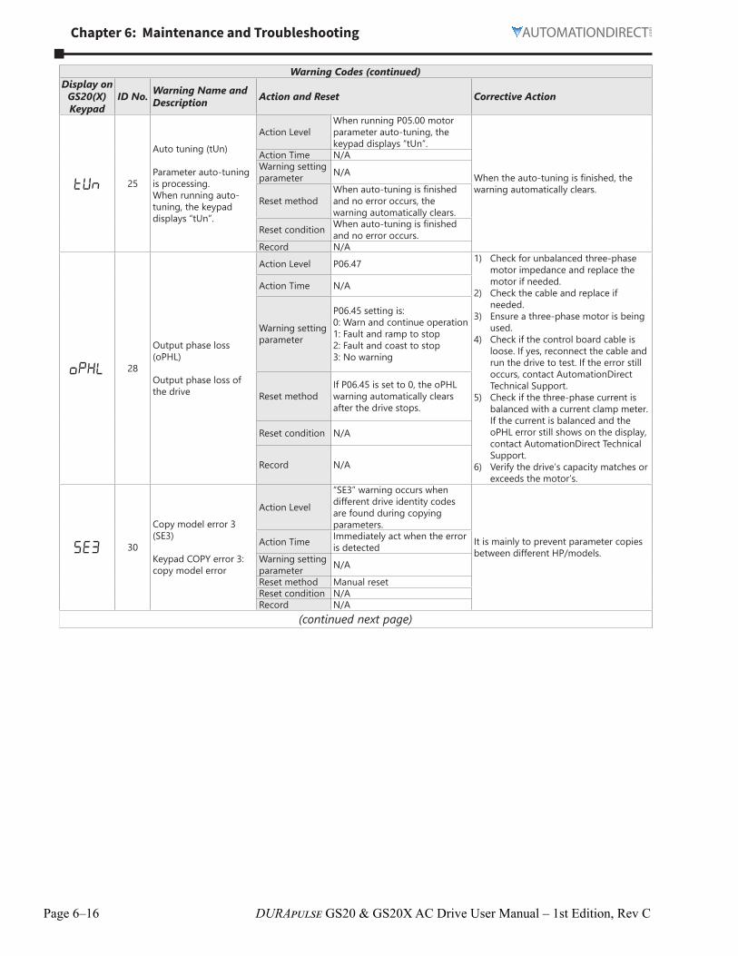
tUn 25
Auto tuning (tUn)
Parameter auto-tuning is processing�When running auto-tuning, the keypad displays “tUn”�
Action LevelWhen running P05�00 motor parameter auto-tuning, the keypad displays “tUn”�
When the auto-tuning is finished, the warning automatically clears�
Action Time N/AWarning setting parameter N/A
Reset methodWhen auto-tuning is finished and no error occurs, the warning automatically clears�
Reset condition When auto-tuning is finished and no error occurs�
Record N/A
oPHL 28
Output phase loss (oPHL)
Output phase loss of the drive
Action Level P06�47 1) Check for unbalanced three-phase motor impedance and replace the motor if needed�
2) Check the cable and replace if needed�
3) Ensure a three-phase motor is being used�
4) Check if the control board cable is loose� If yes, reconnect the cable and run the drive to test� If the error still occurs, contact AutomationDirect Technical Support�
5) Check if the three-phase current is balanced with a current clamp meter� If the current is balanced and the oPHL error still shows on the display, contact AutomationDirect Technical Support�
6) Verify the drive’s capacity matches or exceeds the motor’s�
Action Time N/A
Warning setting parameter
P06�45 setting is:0: Warn and continue operation1: Fault and ramp to stop2: Fault and coast to stop3: No warning
Reset methodIf P06�45 is set to 0, the oPHL warning automatically clears after the drive stops�
Reset condition N/A
Record N/A
SE3 30
Copy model error 3 (SE3)
Keypad COPY error 3: copy model error
Action Level
“SE3” warning occurs when different drive identity codes are found during copying parameters�
It is mainly to prevent parameter copies between different HP/models�
Action Time Immediately act when the error is detected
Page 6–17DURApulse GS20 & GS20X AC Drive User Manual – 1st Edition, Rev C
Warning Codes (continued)Display on
GS20(X) Keypad
ID No. Warning Name and Description Action and Reset Corrective Action
ot3 31Over-torque (ot3)
Over-torque 3 warning
Action Level P14�751) Configure the settings for P14�75 and
P14�76 again�2) Check for mechanical error and
remove the causes of malfunction�3) Verify load and decrease the loading
or replace with a motor with larger capacity if load is too high�
4) Verify accel/decel time and increase the setting values for P01�12–P01�19 (accel�/ decel� time) if work cycle is too short�
5) Verify V/F voltage and adjust the V/F curve (Motor 3, P01�54–P01�61), especially the setting value for the mid-point voltage (if the mid-point voltage is set too small, the load capacity decreases at low-speed)�
6) Replace motor with a larger capacity motor�
7) Check for overload during low-speed operation and decrease the loading during low-speed operation or increase the motor capacity�
8) Verify torque compensation and adjust P07�73 torque compensation gain until the output current decreases and the motor does not stall�
9) Correct the parameter settings for speed tracking� Start the speed tracking function� Adjust the maximum current for P07�09 speed tracking�
Action Time P14�76
Warning setting parameter
P14�74 Over-torque Detection Selection (Motor 3) =1 or 30: No function1: Continue operation after over-torque detection during constant speed operation2: Stop after over-torque detection during constant speed operation3: Continue operation after over-torque detection during RUN4: Stop after over-torque detection during RUN
Reset methodWhen the output current < P14�75, the ot3 warning automatically clears
Reset conditionWhen the output current < P14�75, the ot3 warning automatically clears
Record N/A
(continued next page)
Page 6–18 DURApulse GS20 & GS20X AC Drive User Manual – 1st Edition, Rev C
Chapter 6: Maintenance and Troubleshooting
Warning Codes (continued)Display on
GS20(X) Keypad
ID No. Warning Name and Description Action and Reset Corrective Action
ot4 32Over-torque (ot4)
Over-torque 4 warning
Action Level P14�781) Configure the settings for P14�78 and
P14�79 again�2) Check for mechanical error and
remove the causes of malfunction�3) Verify load and decrease the loading
or replace with a motor with larger capacity if load is too high�
4) Verify accel/decel time and increase the setting values for P01�12–P01�19 (accel�/ decel� time) if work cycle is too short�
5) Verify V/F voltage and adjust the V/F curve (Motor 3, P01�63–P01�70), especially the setting value for the mid-point voltage (if the mid-point voltage is set too small, the load capacity decreases at low-speed)�
6) Replace motor with a larger capacity motor�
7) Check for overload during low-speed operation and decrease the loading during low-speed operation or increase the motor capacity�
8) Verify torque compensation and adjust P07�75 torque compensation gain until the output current decreases and the motor does not stall�
9) Correct the parameter settings for speed tracking� Start the speed tracking function� Adjust the maximum current for P07�09 speed tracking�
Action Time P14�79
Warning setting parameter
P14�77 Over-torque Detection Selection (Motor 4) =1 or 30: No function1: Continue operation after over-torque detection during constant speed operation2: Stop after over-torque detection during constant speed operation3: Continue operation after over-torque detection during RUN4: Stop after over-torque detection during RUN
Reset methodWhen the output current < P14�78, the ot4 warning automatically clears
Reset conditionWhen the output current < P14�79, the ot4 warning automatically clears
Record N/A
PLod 50
PLC opposite defect (PLod)
PLC download error warning
Action Level
During PLC downloading, the program source code detects incorrect address (e�g� the address exceeds the range), then the PLod warning occurs�
Verify the data number used when downloading the PLC program and use the correct data number�
Action Time Immediately act when the fault is detected
Warning setting parameter N/A
Reset method
Check if the program is correct and download the program again� If the fault does not exist, the warning automatically clears�
Reset condition N/ARecord N/A
PLSv 51
PLC save memory error (PLSv)
Data error during PLC operation
Action Level
The program detects incorrect written address (e�g� the address exceeds the range) during PLC operation, then the PLSv warning occurs�
Make sure the written address is correct and download the program again�
Action Time Immediately act when the fault is detected
Warning setting parameter N/A
Reset method
Check if the program is correct and download the program again� If the fault does not exist, the warning automatically clears�
Reset condition N/ARecord N/A
(continued next page)
Chapter 6: Maintenance and Troubleshooting
Page 6–19DURApulse GS20 & GS20X AC Drive User Manual – 1st Edition, Rev C
Warning Codes (continued)Display on
GS20(X) Keypad
ID No. Warning Name and Description Action and Reset Corrective Action
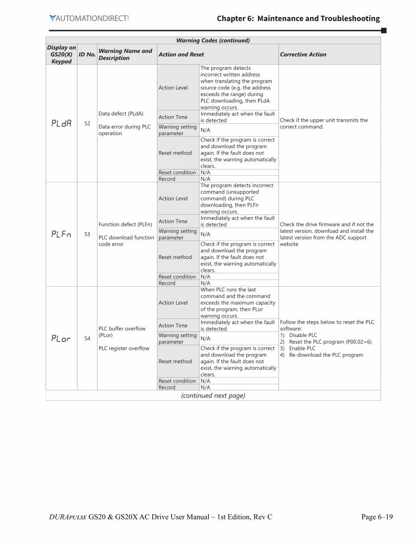
PLdA 52
Data defect (PLdA)
Data error during PLC operation
Action Level
The program detects incorrect written address when translating the program source code (e�g� the address exceeds the range) during PLC downloading, then PLdA warning occurs�
Check if the upper unit transmits the correct command�
Action Time Immediately act when the fault is detected
Warning setting parameter N/A
Reset method
Check if the program is correct and download the program again� If the fault does not exist, the warning automatically clears�
Reset condition N/ARecord N/A
PLFn 53
Function defect (PLFn)
PLC download function code error
Action Level
The program detects incorrect command (unsupported command) during PLC downloading, then PLFn warning occurs�
Check the drive firmware and if not the latest version, download and install the latest version from the ADC support website
Action Time Immediately act when the fault is detected
Warning setting parameter N/A
Reset method
Check if the program is correct and download the program again� If the fault does not exist, the warning automatically clears�
Reset condition N/ARecord N/A
PLor 54
PLC buffer overflow (PLor)
PLC register overflow
Action Level
When PLC runs the last command and the command exceeds the maximum capacity of the program, then PLor warning occurs�
Follow the steps below to reset the PLC software:1) Disable PLC2) Reset the PLC program (P00�02=6)3) Enable PLC4) Re-download the PLC program
Action Time Immediately act when the fault is detected
Warning setting parameter N/A
Reset method
Check if the program is correct and download the program again� If the fault does not exist, the warning automatically clears�
Reset condition N/ARecord N/A
(continued next page)
Page 6–20 DURApulse GS20 & GS20X AC Drive User Manual – 1st Edition, Rev C
Chapter 6: Maintenance and Troubleshooting
Warning Codes (continued)Display on
GS20(X) Keypad
ID No. Warning Name and Description Action and Reset Corrective Action
PLFF 55
Function defect (PLFF)
Function code error during PLC operation
Action Level
The program detects incorrect command (unsupported command) during PLC operation, then PLFF warning occurs�
When starting the PLC function and there is no program in the PLC, the PLFF warning occurs� This is a normal warning, please download the program�
Action Time Immediately act when the fault is detected
Warning setting parameter NA
Reset method
Check if the program is correct and download the program again� If the fault does not exist, the warning automatically clears�
Reset condition N/ARecord N/A
PLSn 56Checksum error (PLSn)
PLC checksum error
Action LevelPLC checksum error is detected after the drive is powered on, then PLSn warning occurs�
Follow the steps below to reset the PLC software:1) Disable PLC2) Reset the PLC program (P00�02=6)3) Enable PLC4) Re-download the PLC program
Action Time Immediately act when the fault is detected
Warning setting parameter NA
Reset method
Check if the program is correct and download the program again� If the fault does not exist, the warning automatically clears�
Reset condition N/ARecord N/A
PLEd 57
No end command (PLEd)
PLC end command is missing
Action Level
The “End” command is missing� Until the last command is executed, the PLEd warning occurs�
Follow the steps below to reset the PLC software:1) Disable PLC2) Reset the PLC program (P00�02=6)3) Enable PLC4) Re-download the PLC program
Action Time Immediately act when the fault is detected
Warning setting parameter NA
Reset method
Check if the program is correct and download the program again� If the fault does not exist, the warning automatically clears�
Reset condition N/ARecord N/A
PLCr 58
PLC MCR error (PLCr)
PLC MCR command error
Action Level
The MC command is detected during PLC operation, but there is no corresponding MCR command, then the PLCr warning occurs�
The MC command cannot be used continuously for 9 times� Check and reset the program, then re-download the program�
Action Time Immediately act when the fault is detected
Warning setting parameter NA
Reset method
Check if the program is correct and download the program again� If the fault does not exist, the warning automatically clears�
Reset condition N/ARecord N/A
(continued next page)
Chapter 6: Maintenance and Troubleshooting
Page 6–21DURApulse GS20 & GS20X AC Drive User Manual – 1st Edition, Rev C
Warning Codes (continued)Display on
GS20(X) Keypad
ID No. Warning Name and Description Action and Reset Corrective Action
PLdF 59
PLC download fail (PLdF)
PLC download failure
Action Level
PLC download failure due to momentary power loss during download� After the power is again present, the PLdF warning occurs�
Check for programming errors, if they exist, correct and download the program again�
Action Time Immediately act when the fault is detected
Warning setting parameter NA
Reset method
Check for programming errors, if they exist, correct and download the program again� If the fault does not exist, the warning automatically clears�
Reset condition N/ARecord N/A
PLSF 60
PLC scan time fail (PLSF)
PLC scan time exceeds the maximum allowable time
Action Level
When the PLC scan time exceeds the maximum allowable time (400 ms), the PLSF warning occurs�
Check for Source Code errors, if they exist, correct and download the program again�
Action Time Immediately act when the fault is detected
Warning setting parameter NA
Reset method
Check for programming errors, if they exist, correct and download the program again� If the fault does not exist, the warning automatically clears�
Reset condition N/ARecord N/A
ECLv 71
ExCom power loss (ECLv)
Low voltage of the communication card
Action LevelThe 5V power that the drive provides to the communication card is too low
1) Make sure the communication card is well inserted and not loose�
2) Use the same communication card with another GS20 drive to check if the ECLv warning still occurs� If yes, replace with a new communication card; if not, replace the drive�
3) Use another communication card to test if the ECLv warning still occurs on the same drive� If not, replace the card; if yes, replace the drive�
Action Time Immediately actWarning setting parameter N/A
Reset method Cycle the powerReset condition N/A
Record N/A
ECtt 72
ExCom test mode (ECtt)
The communication card is in the test mode
Action Level The communication card is in the test mode
Cycle the power
Action Time Immediately actWarning setting parameter N/A
Reset method Cycle the power and enter the normal mode
Reset condition N/ARecord N/A
ECFF 75
ExCom factory defect (ECFF)
Factory default setting error
Action Level Factory default setting error
Use GSoft2 to download a new parameter set into the drive�
Action Time Immediately actWarning setting parameter N/A
Reset method Cycle the powerReset condition N/ARecord N/A
(continued next page)
Page 6–22 DURApulse GS20 & GS20X AC Drive User Manual – 1st Edition, Rev C
Chapter 6: Maintenance and Troubleshooting
Warning Codes (continued)Display on
GS20(X) Keypad
ID No. Warning Name and Description Action and Reset Corrective Action
ECiF 76
ExCom inner error (ECiF)
Serious internal error
Action Level Internal memory saving error 1) Verify the wiring of the control circuit, and the wiring/grounding of the main circuit to prevent interference�
2) Cycle the power�3) Reset to the default value and check
if the error still exists� If yes, replace the communication card�
Action Time Immediately actWarning setting parameter N/A
Reset method Cycle the powerReset condition N/A
Record N/A
ECEF 80
Ethernet link fail (ECEF)
The Ethernet cable is not connected
Action Level Hardware detection
1) Re-connect the cable2) Replace the cable
Action Time Immediately actWarning setting parameter N/A
Modbus TCP exceeds the maximum communication value
Action Level Hardware detection1) Verify the Master communication
value does not exceed the allowable number of communication cards�If it does, decrease the Master communication value�
2) Check if the connection is occupied due to not disconnecting the Modbus TCP while the upper unit is connected without communicating� If it is, revise the program of the upper unit to disconnect the connection while the communication is not used for a long time�
3) Check if a new Modbus TCP connection is built whenever the upper unit is connected to the communication card� If so, revise the program of the upper unit to use the same Modbus TCP connection when connecting to the same communication card�
Action Time Immediately act
Warning setting parameter N/A
Reset method Manual reset
Reset condition Immediately reset
Record N/A
(continued next page)
Chapter 6: Maintenance and Troubleshooting
Page 6–23DURApulse GS20 & GS20X AC Drive User Manual – 1st Edition, Rev C
Warning Codes (continued)Display on
GS20(X) Keypad
ID No. Warning Name and Description Action and Reset Corrective Action
ECo1 85
EtherNet/IP over (ECo1)
EtherNet/IP exceeds the maximum communication value
Action Level Hardware detection1) Verify the Master communication
value does not exceed the allowable number of communication cards�If it does, decrease the Master communication value�
2) Check if the connection is occupied due to not disconnecting the Modbus TCP while the upper unit is connected without communicating� If it is, revise the program of the upper unit to disconnect the connection while the communication is not used for a long time�
3) Check if a new Modbus TCP connection is built whenever the upper unit is connected to the communication card� If so, revise the program of the upper unit to use the same Modbus TCP connection when connecting to the same communication card�
Action Time Immediately act
Warning setting parameter N/A
Reset method Manual reset
Reset condition Immediately reset
Record N/A
ECiP 86IP fail (ECiP)
IP setting error
Action Level Software detection
1) Reset IP2) Contact MIS to check if DHCP Server
works normally
Action Time Immediately actWarning setting parameter N/A
When P09�31= (-1) – (-10) (no -9) and the internal communication between Master and Slave is abnormal, the ictn warning occurs�
1) Verify the wiring and grounding of the communication circuit� Separate the communication circuit from the main circuit, or wire in 90 degree for effective anti-interference performance�
2) Check if the setting for P09�04 is the same as the setting for the upper unit
3) Check the cable and replace it if necessary�
Action Time Immediately actWarning setting parameter N/A
Reset method Auto-reset
Reset conditionThe warning automatically clears when the communication is back to normal condition
Record N/A
Chapter 6: Maintenance and Troubleshooting
Page 6–25DURApulse GS20 & GS20X AC Drive User Manual – 1st Edition, Rev C
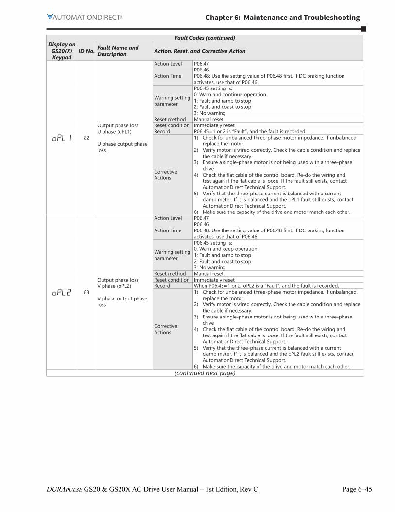
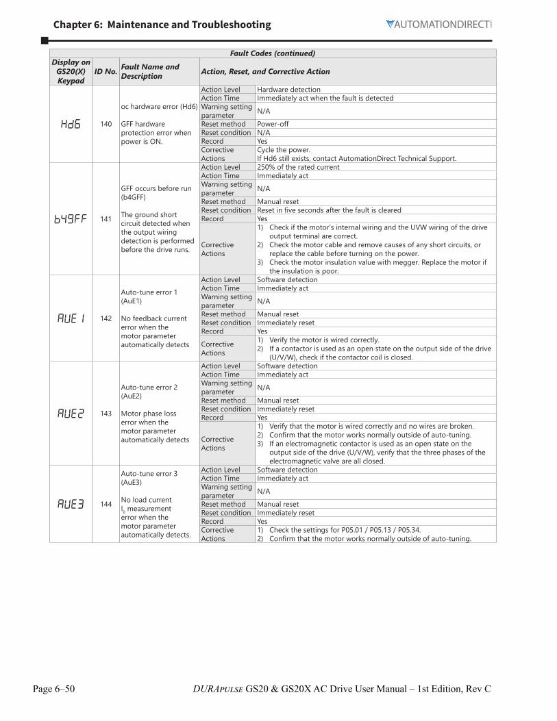
Fault CodesThe GS20(X) drive has a comprehensive fault diagnostic system that include a variety of fault messages. When a fault is detected, the GS20(X) drive will shut down in order to protect internal components. The following faults are displayed as shown on the GS20(X) digital keypad display.For communication errors, “Upper unit” is referring to the Master controller of the serial network. Always ensure the communication settings of the drive (P09.01 and P09.04) match those of the master controller and network.
Gaps in the fault ID numbers below are set aside as “reserved” faults for possible future use. Should your GS20(X) drive repeatedly display a reserved fault, please note the fault ID number and contact AutomationDirect technical support.
Fault CodesDisplay on
GS20(X) Keypad
ID No. Fault Name and Description Action, Reset, and Corrective Action
ocA 1
Over-current during acceleration (ocA)
Output current exceeds three times of the rated current during acceleration�When ocA occurs, the drive closes the gate of the output immediately, the motor runs freely, and the display shows an ocA error�
Action Level 300% of the rated currentAction Time Immediately actWarning setting parameter N/A
Reset method Manual resetReset condition Reset in five seconds after the fault is clearedRecord Yes
Corrective Actions
1) Check acceleration time� If too short:a) Increase the acceleration timeb) Increase the acceleration time of S-curvec) Set auto-acceleration and auto-deceleration parameter (P01�44)d) Set over-current stall prevention function (P06�03)e) Replace the drive with a larger capacity model�
2) Check the motor cable and remove causes of any short circuits, or replace the cable before turning on the power�
3) Check the motor insulation value with megger� Replace the motor if the insulation is poor�
4) Check if the output current during the whole working process exceeds the AC motor drive’s rated current� If yes, replace the AC motor drive with a larger capacity model�
5) Reduce the load or increase the capacity of AC motor drive�6) Check the motor capacity (the rated current on the motor’s
nameplate should ≤ the rated current of the drive)�7) Check the action timing of the contactor and make sure it is not
turned ON/OFF when the drive outputs the voltage� 8) Adjust the V/F curve setting and frequency/voltage� When the fault
occurs, and the frequency voltage is too high, reduce the voltage� 9) Adjust the torque compensation (refer to P07�26 torque
compensation gain) until the output current reduces and the motor does not stall�
10) Verify the wiring of the control circuit and the wiring/grounding of the main circuit to prevent interference�
11) Enable speed tracking during start-up of P07�12� 12) Correct the parameter settings for speed tracking�
a) Start the speed tracking function�b) Adjust the maximum current for P07�09 speed tracking�
13) Check the settings for P00�11 control mode:a) For IM, P00�11=0, 1, 2, 5b) For PM, P00�11=2
14) Increase the AC motor drive’s capacity�15) Install AC reactor(s) on the output side (U/V/W)�
(continued next page)
Page 6–26 DURApulse GS20 & GS20X AC Drive User Manual – 1st Edition, Rev C
Chapter 6: Maintenance and Troubleshooting
Fault Codes (continued)Display on
GS20(X) Keypad
ID No. Fault Name and Description Action, Reset, and Corrective Action
ocA 1 ocA (continued) Corrective Actions (cont’d)
16) In the case of hardware failure, the ocA occurs due to the short circuit or ground fault at the output side of the drive�a) Check for possible short circuits between terminals with the
electric meter:b) B1 corresponds to U, V and W; DC- corresponds to U, V and W;
corresponds to U, V and W�c) If short circuit occurs, contact AutomationDirect Technical
Support� 17) Check the stall prevention setting and set the stall prevention to the
proper value�
ocd 2
Over-current during deceleration (ocd)
Output current exceeds three times of the rated current during deceleration�When ocd occurs, the drive closes the gate of the output immediately, the motor runs freely, and the display shows an ocd error�
Action Level 300% of the rated currentAction Time Immediately actWarning setting parameter N/A
Reset method Manual resetReset condition Reset in five seconds after the fault is clearedRecord Yes
Corrective Actions
1) Check if the deceleration time is too short� If so:a) Increase the deceleration timeb) Increase the deceleration time of S-curvec) Set auto-acceleration and auto-deceleration parameter (P01�44)d) Set over-current stall prevention function (P06�03)e) Replace the drive with a larger capacity model
2) Check if the mechanical brake of the motor activates too early�3) Check the motor cable and remove causes of any short circuits, or
replace the cable before turning on the power�4) Check the motor insulation value with megger� Replace the motor if
the insulation is poor�5) Check if the output current during the whole working process exceeds
the AC motor drive’s rated current� If yes, replace the AC motor drive with a larger capacity model�
6) Check the impulsive change of the load and reduce the load or increase the capacity of AC motor drive as needed�
7) Verify the motor capacity, the rated current on the motor’s nameplate should ≤ the rated current of the drive�
8) If using an ON/OFF controller at the (U/V/W) drive output, check the action timing of the contactor and make sure it is not turned ON/OFF when the drive outputs the voltage�
9) Adjust the V/F curve settings and frequency/voltage� When the fault occurs, and the frequency voltage is too high, reduce the voltage�
10) Adjust the P07�26 torque compensation gain until the output current reduces and the motor does not stall�
11) Verify the wiring of the control circuit and the wiring/grounding of the main circuit to prevent interference�
12) Check the length of the motor cable� If it is too long, increase the AC motor drive’s capacity or install AC reactor(s) on the output side (U/V/W)�
13) In the case of a hardware error, the ocd occurs due to the short circuit or ground fault at the output side of the drive�a) Check for possible short circuits between terminals with the
electric meter:b) B1 corresponds to U, V and W; DC- corresponds to U, V and W;
corresponds to U, V and W�c) If short circuits occurs, contact AutomationDirect Technical
Support� 14) Verify the stall prevention setting and set the stall prevention to the
proper value�(continued next page)
Chapter 6: Maintenance and Troubleshooting
Page 6–27DURApulse GS20 & GS20X AC Drive User Manual – 1st Edition, Rev C
Fault Codes (continued)Display on
GS20(X) Keypad
ID No. Fault Name and Description Action, Reset, and Corrective Action
ocn 3
Over-current during steady operation (ocn)
Output current exceeds three times of the rated current during constant speed�When ocn occurs, the drive closes the gate of the output immediately, the motor runs freely, and the display shows an ocn error�
Action Level 300% of the rated currentAction Time Immediately actWarning setting parameter N/A
Reset method Manual resetReset condition Reset in five seconds after the fault is clearedRecord Yes
Corrective Actions
1) Check the motor cable and remove causes of any short circuits, or replace the cable before turning on the power�
2) Check for possible shaft lock, burnout or aging insulation of the motor�a) Check the motor insulation value with megger� Replace the motor
if the insulation is poor� 3) Check for impulsive change of the load, and reduce the load or
increase the capacity of AC motor drive�4) Check motor capacity (the rated current on the motor’s nameplate
should ≤ the rated current of the drive) 5) If using an ON/OFF controller at the drive output, check the action
timing of the contactor and make sure it is not turned ON/OFF when the drive outputs the voltage�
6) Adjust the V/F curve settings and frequency/voltage� When the fault occurs, and the frequency voltage is too high, reduce the voltage�
7) Adjust P07�26 torque compensation gain until the output current reduces and the motor does not stall�
8) Verify the wiring of the control circuit and the wiring/grounding of the main circuit to prevent interference�
9) Check the length of the motor cable� If too long:a) Increase the AC motor drive’s capacity�b) Install AC reactor(s) on the output side (U/V/W)�
10) In the case of hardware failure, the ocn may occur due to a short circuit or ground fault at the output side of the drive�a) Check for possible short circuit between terminals with the
electric meter:b) B1 corresponds to U, V and W; DC- corresponds to U, V, and W;
corresponds to U, V, and W�c) If short circuits occurs, contact AutomationDirect Technical
Support�
GFF 4
Ground fault (GFF)
When the drive detects grounding short circuit on the output terminals (U/V/W), the drive closes the gate of the output immediately, the motor runs freely, and the display shows a GFF error�
Action Level N/AAction Time N/AWarning setting parameter N/A
Reset method Manual resetReset condition Reset in five seconds after the fault is clearedRecord Yes
Corrective Actions
1) Check for motor burnout or aging insulation�a) Check the motor insulation value with megger� b) Replace the motor if the insulation is poor�
2) Check the cable for short circuits and replace the cable if needed�3) If the motor cable length exceeds 100 m, decrease the setting
value for the carrier frequency and take remedies to reduce stray capacitance�
4) Verify the grounding and wiring of the communication circuit� Separate the communication circuit from the main circuit, or wire in 90 degree for effective anti-interference performance�
5) Cycle the power after checking the status of motor, cable, and cable length� If GFF still exists, contact AutomationDirect Technical Support�
6) Refer to the corrective actions for ocn�7) Refer to the corrective actions for ocA�8) Refer to the corrective actions for ocd�
(continued next page)
Page 6–28 DURApulse GS20 & GS20X AC Drive User Manual – 1st Edition, Rev C
Chapter 6: Maintenance and Troubleshooting
Fault Codes (continued)Display on
GS20(X) Keypad
ID No. Fault Name and Description Action, Reset, and Corrective Action
ocS 6
Over-current at stop (ocS)
Over-current or hardware failure in current detection at stop�Cycle the power after ocS occurs� If the hardware failure occurs, the display shows cd1, cd2 or cd3�
Action Level 300% of the rated currentAction Time Immediately actWarning setting parameter N/A
Reset method Manual resetReset condition Reset in five seconds after the fault is clearedRecord Yes
Corrective Actions
1) Verify the wiring of the control circuit and the wiring/grounding of the main circuit to prevent interference�
2) Check if other error codes such as cd1–cd3 occur after cycling the power� If yes, return to the factory for repair�
ovA 7
Over-voltage during acceleration (ovA)
DC bus over-voltage during acceleration�When ovA occurs, the drive closes the gate of the output, the motor runs freely, and the display shows an ovA error�
Action Time Immediately act when the DC bus voltage is higher than the levelWarning setting parameter N/A
Reset method Manual reset
Reset condition Reset only when the DC bus voltage is lower than 90% of the over-voltage level
Record Yes
Corrective Actions
1) Check acceleration� If too slow:a) Decrease the acceleration timeb) Use a braking unit or DC busc) Replace the drive with a larger capacity model�
2) Check the setting for stall prevention level� If the value is lower than no-load current, adjust it to be higher than no-load current�
3) Check if the input voltage is within the rated AC motor drive input voltage range, and check for possible voltage spikes�
4) If the phase-in capacitor or active power supply unit acts in the same power system, the input voltage may surge abnormally in a short time� In this case, install an AC reactor�
5) Check for regenerative voltage of motor inertia� If regenerative voltage is being generated:a) Use over-voltage stall prevention function (P06�01)b) Use auto-acceleration and auto-deceleration setting (P01�44)c) Use a braking unit or DC bus
6) Check if the over-voltage warning occurs after acceleration stops, which indicates acceleration time is too short� Do the following:a) Increase the acceleration timeb) Set P06�01 over-voltage stall preventionc) Increase the setting value for P01�25 S-curve acceleration arrival
time 27) The ground short circuit current charges the capacitor in the main
circuit through the power� Check if there is a ground fault on the motor cable, wiring box, or its internal terminals�
8) If using a braking resistor or brake unit, check the wiring�9) Verify the wiring of the control circuit and the wiring/grounding of
the main circuit to prevent interference�(continued next page)
Chapter 6: Maintenance and Troubleshooting
Page 6–29DURApulse GS20 & GS20X AC Drive User Manual – 1st Edition, Rev C
Fault Codes (continued)Display on
GS20(X) Keypad
ID No. Fault Name and Description Action, Reset, and Corrective Action
ovd 8
Over-voltage during deceleration (ovd)
DC bus over-voltage during deceleration�When ovd occurs, the drive closes the gate of the output immediately, the motor runs freely, and the display shows an ovd error�
Action Time Immediately act when the DC bus voltage is higher than the levelWarning setting parameter N/A
Reset method Manual reset
Reset condition Reset only when the DC bus voltage is lower than 90% of the over-voltage level
Record Yes
Corrective Actions
1) Deceleration time may be too short, resulting in too much regenerative energy�a) Increase the setting value of P01�13, P01�15, P01�17 and P01�19
(deceleration time)b) Connect a braking resistor, braking unit or DC bus on the drive�c) Reduce the braking frequency�d) Replace the drive with a larger capacity model�e) Use S-curve acceleration/deceleration�f) Use over-voltage stall prevention (P06�01)�g) Use auto-acceleration and auto-deceleration (P01�44)�h) Adjust the braking level (P07�01 or the bolt position of the
braking unit)�2) Verify that the setting for stall prevention level is larger than no-load
current3) Check if the input voltage is within the rated AC motor drive input
voltage range, and check for possible voltage spikes�4) If the phase-in capacitor or active power supply unit acts in the same
power system, the input voltage may surge abnormally in a short time� In this case, install an AC reactor�
5) The ground short circuit current charges the capacitor in the main circuit through the power� Check if there is ground fault on the motor cable, wiring box, or its internal terminals�
6) If using a braking resistor or braking unit, check the wiring�7) Verify the wiring of the control circuit and the wiring/grounding of
the main circuit to prevent interference�
ovn 9
Over-voltage during constant speed (ovn)
DC bus over-voltage at constant speed�When ovn occurs, the drive closes the gate of the output immediately, the motor runs freely, and the display shows an ovn error�
Action Time Immediately act when the DC bus voltage is higher than the levelWarning setting parameter N/A
Reset method Manual reset
Reset condition Reset only when the DC bus voltage is lower than 90% of the over-voltage level
Record Yes
Corrective Actions
1) Check for impulsive change of the load, then do the following:a) Connect a brake resistor, braking unit or DC bus to the drive�b) Reduce the load�c) Replace the drive with a larger capacity model�d) Adjust the braking level (P07�01 or bolt position of the brake
unit)�2) Verify the stall prevention level setting is higher than no-load current�3) Check for regenerative voltage, then enable over-voltage stall
prevention function (P06�01) or use a braking unit or DC bus4) Check if the input voltage is within the rated AC motor drive input
voltage range, and check for possible voltage spikes�5) If the phase-in capacitor or active power supply unit acts in the same
power system, the input voltage may surge abnormally in a short time� In this case, install an AC reactor�
6) The ground short circuit current charges the capacitor in the main circuit through the power� Check if there is ground fault on the motor cable, wiring box, or its internal terminals�
7) If using a braking resistor or braking unit, check the wiring�8) Verify the wiring of the control circuit and the wiring/grounding of
the main circuit to prevent interference�(continued next page)
Page 6–30 DURApulse GS20 & GS20X AC Drive User Manual – 1st Edition, Rev C
Chapter 6: Maintenance and Troubleshooting
Fault Codes (continued)Display on
GS20(X) Keypad
ID No. Fault Name and Description Action, Reset, and Corrective Action
Action Time Immediately act when the DC bus voltage is higher than the levelWarning setting parameter N/A
Reset method Manual reset
Reset condition Reset only when the DC bus voltage is lower than 90% of the over-voltage level
Record Yes
Corrective Actions
1) Check if the input voltage is within the rated AC motor drive input voltage range, and check for possible voltage spikes�
2) If the phase-in capacitor or active power supply unit acts in the same power system, the input voltage may surge abnormally in a short time� In this case, install an AC reactor�
3) The ground short circuit current charges the capacitor in the main circuit through the power� Check if there is ground fault on the motor cable, wiring box, or its internal terminals�
4) If using a braking resistor or braking unit, check the wiring�5) Verify the wiring of the control circuit and the wiring/grounding of
the main circuit to prevent interference�6) Check if other error codes such as cd1–cd3 occur after cycling the
power� If yes, contact AutomationDirect Technical Support�
LvA 11
Low-voltage during acceleration (LvA)
DC bus voltage is lower than P06�00 setting value during acceleration
Action Level
P06�00 (120V/230V series = 180VDC460V series = 360VDC575V series = 450VDC)
Action Time Immediately act when the DC bus voltage is lower than P06�00Warning setting parameter N/A
Reset method Manual resetReset condition Reset when the DC bus voltage is higher than P06�00 + 30 VRecord Yes
Corrective Actions
1) Improve power supply condition�2) Adjust voltage to the power range of the drive3) Check the power system and increase the capacity of power
equipment if needed�4) The load may be too heavy� If so:
a) Reduce the load�b) Increase the drive capacity�c) Increase the acceleration time�
5) Check the DC bus and install DC reactor(s)�6) Check for a short circuit plate or DC reactor installed between
terminal +1 and +2� Connect short circuit plate or DC reactor between terminal +1 and +2�
7) If the error still exists, contact AutomationDirect Technical Support�
Lvd 12
Low-voltage during deceleration (Lvd)
DC bus voltage is lower than P06�00 setting value during deceleration
Action Level
P06�00(120V/230V series = 180VDC460V series = 360VDC575V series = 450VDC)
Action Time Immediately act when the DC bus voltage is lower than P06�00Warning setting parameter N/A
Reset method Manual resetReset condition Reset when the DC bus voltage is higher than P06�00 + 30 V Record Yes
Corrective Actions
1) Improve power supply condition�2) Adjust voltage to the power range of the drive3) Check the power system and increase the capacity of power
equipment if needed�4) The fault may be triggered by sudden load� If so:
a) Reduce the load�b) Increase the drive capacity�
5) Check the DC bus and install DC reactor(s)�(continued next page)
Chapter 6: Maintenance and Troubleshooting
Page 6–31DURApulse GS20 & GS20X AC Drive User Manual – 1st Edition, Rev C
Fault Codes (continued)Display on
GS20(X) Keypad
ID No. Fault Name and Description Action, Reset, and Corrective Action
Lvn 13
Low-voltage at constant speed (Lvn)
DC bus voltage is lower than P06�00 setting value at constant speed
Action Level
P06�00(120V/230V series = 180VDC460V series = 360VDC575V series = 450VDC)
Action Time Immediately act when the DC bus voltage is lower than P06�00Warning setting parameter N/A
Reset method Manual resetReset condition Reset when the DC bus voltage is higher than P06�00 + 30 VRecord Yes
Corrective Actions
1) Improve power supply condition�2) Adjust voltage to the power range of the drive3) Check the power system and increase the capacity of power
equipment if needed�4) The fault may be triggered by sudden load� If so:
a) Reduce the load�b) Increase the drive capacity�
5) Check the DC bus and install DC reactor(s)�
LvS 14
Low-voltage at stop (LvS)
DC bus voltage is lower than P06�00 setting value at stop or a hardware failure in voltage detection had occurred�
Action Level
P06�00(120V/230V series = 180VDC460V series = 360VDC575V series = 450VDC)
Action Time Immediately act when the DC bus voltage is lower than P06�00Warning setting parameter N/A
1) Improve power supply condition�2) Check if the power specification matches the drive�3) Adjust voltage to the power range of the drive�4) Cycle the power after checking the power� If LvS error still exists,
return to the factory for repair�5) Check the power system�6) Increase the capacity of power equipment�7) Install DC reactor(s)�
orP 15
Phase loss protection (orP)
Phase loss of power input
Action LevelWhen DC bus ripple is higher than the protection level, and the output current exceeds 50% of the rated current, the drive starts counting� When the counting value reaches the upper limit, an orP error occurs�
Action Time The action time varies with different output current�Warning setting parameter P06�53
Reset method Manual resetReset condition Immediately reset when DC bus is higher than P07�00Record Yes
Corrective Actions
1) Verify the wiring of the main circuit power is installed correctly�2) Check that a single-phase power supply is not being used with a
three-phase model� Choose the model whose power matches the voltage�
3) Power voltage changes can trigger this fault� If the main circuit power works normally, verify the main circuit� Cycle the power after checking the power, if orP error still exists, contact AutomationDirect Technical Support�
4) Check for loose terminal wiring, tighten the terminal screws according to the torque described in the user manual�
5) Verify the input cable is undamaged and replace if needed�6) Check for unbalanced three-phase input power�
(continued next page)
Page 6–32 DURApulse GS20 & GS20X AC Drive User Manual – 1st Edition, Rev C
Chapter 6: Maintenance and Troubleshooting
Fault Codes (continued)Display on
GS20(X) Keypad
ID No. Fault Name and Description Action, Reset, and Corrective Action
oH1 16
IGBT overheating (oH1)
IGBT temperature exceeds the protection level�
Protection level is model default of P06�15 + 5°C
Action Level
Depending on the model power, model default of P06�15 +5°C�When the setting for P06�15 is higher than the oH1 level, oH1 error occurs instead of oH1 warning� An IGBT overheating error occurs, and the drive stops�
Action Time Immediately when limit is reached�Warning setting parameter N/A
Reset method Manual reset
Reset condition Reset only when IGBT temperature is lower than oH1 error level minus (-) 10°C
Record Yes
Corrective Actions
1) Check the ambient temperature�2) Regularly inspect the ventilation hole of the control cabinet�3) Change the installed location if there are heating objects, such as
braking resistors, in the surroundings� 4) Install/add cooling fan or air conditioner to lower the temperature
inside the cabinet�5) Check for and remove obstructions or replace the cooling fan�6) Increase ventilation space of the drive�7) Decrease loading�8) Decrease the carrier wave�9) Replace the drive with higher capacity model�
tH1o 18
IGBT temperature detection failure (tH1o)
IGBT hardware failure in temperature detection
Action Level NTC broken or wiring failure
Action Time When the IGBT temperature is higher than the protection level, and detection time exceeds 100 ms, the tH1o protection activates�
Wait for 10 minutes, and then cycle the power� Check if tH1o protection still exists� If yes, contact AutomationDirect Technical Support�
oL 21
Over load (oL)
The AC motor drive detects excessive drive output current�Overload capacity:• Variable Torque (VT):
Sustains for one minute when the drive outputs 120% of the drive’s rated output current�Sustains for three seconds when the drive outputs 150% of the drive’s rated output current�
• Constant Torque (CT): Sustains for one minute when the drive outputs 150% of the drive’s rated output current� Sustains for three seconds when the drive outputs 200% of the drive’s rated output current�
Action Level Based on overload curve and derating curve�
Action Time When the load is higher than the protection level and exceeds allowable time, the oL protection activates�
Warning setting parameter N/A
Reset method Manual resetReset condition Reset in five seconds after the fault is clearedRecord Yes
Corrective Actions
1) Reduce the load�2) Increase the setting value for P01�12–P01�19 (accel�/decel� time)3) Adjust the settings for P01�01–P01�08 (V/F curve), especially the
setting value for the mid-point voltage (if the mid-point voltage is set too low, the load capacity decreases at low speed)� Refer to the V/F curve selection of P01�43�
4) Replace the drive with a larger capacity model�5) If the oL only occurs during low-speed operations:
a) Reduce the load during low-speed operation�b) Increase the drive capacity�c) Decrease the carrier frequency of P00�17�
6) Adjust P07�26 Torque Compensation Gain until the output current reduces and the motor does not stall�
7) Verify stall prevention is set to the proper value�8) Check the status of three-phase motor and verify the cable is not
broken or screws are loose�9) Verify the parameter settings for speed tracking�
a) Start the speed tracking function�b) Adjust the maximum current for P07�09 speed tracking�
(continued next page)
Chapter 6: Maintenance and Troubleshooting
Page 6–33DURApulse GS20 & GS20X AC Drive User Manual – 1st Edition, Rev C
Fault Codes (continued)Display on
GS20(X) Keypad
ID No. Fault Name and Description Action, Reset, and Corrective Action
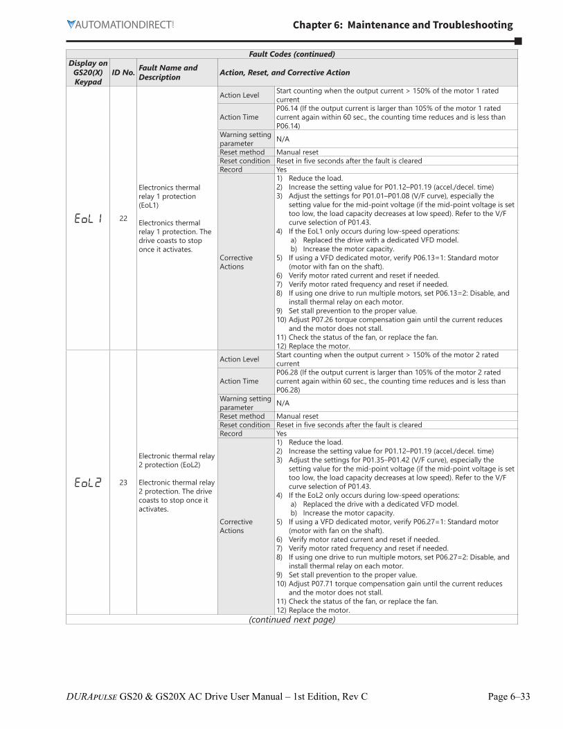
EoL1 22
Electronics thermal relay 1 protection (EoL1)
Electronics thermal relay 1 protection� The drive coasts to stop once it activates�
Action Level Start counting when the output current > 150% of the motor 1 rated current
Action TimeP06�14 (If the output current is larger than 105% of the motor 1 rated current again within 60 sec�, the counting time reduces and is less than P06�14)
Warning setting parameter N/A
Reset method Manual resetReset condition Reset in five seconds after the fault is clearedRecord Yes
Corrective Actions
1) Reduce the load�2) Increase the setting value for P01�12–P01�19 (accel�/decel� time)3) Adjust the settings for P01�01–P01�08 (V/F curve), especially the
setting value for the mid-point voltage (if the mid-point voltage is set too low, the load capacity decreases at low speed)� Refer to the V/F curve selection of P01�43�
4) If the EoL1 only occurs during low-speed operations:a) Replaced the drive with a dedicated VFD model�b) Increase the motor capacity�
5) If using a VFD dedicated motor, verify P06�13=1: Standard motor (motor with fan on the shaft)�
6) Verify motor rated current and reset if needed�7) Verify motor rated frequency and reset if needed�8) If using one drive to run multiple motors, set P06�13=2: Disable, and
install thermal relay on each motor�9) Set stall prevention to the proper value�10) Adjust P07�26 torque compensation gain until the current reduces
and the motor does not stall�11) Check the status of the fan, or replace the fan�12) Replace the motor�
EoL2 23
Electronic thermal relay 2 protection (EoL2)
Electronic thermal relay 2 protection� The drive coasts to stop once it activates�
Action Level Start counting when the output current > 150% of the motor 2 rated current
Action TimeP06�28 (If the output current is larger than 105% of the motor 2 rated current again within 60 sec�, the counting time reduces and is less than P06�28)
Warning setting parameter N/A
Reset method Manual resetReset condition Reset in five seconds after the fault is clearedRecord Yes
Corrective Actions
1) Reduce the load�2) Increase the setting value for P01�12–P01�19 (accel�/decel� time)3) Adjust the settings for P01�35–P01�42 (V/F curve), especially the
setting value for the mid-point voltage (if the mid-point voltage is set too low, the load capacity decreases at low speed)� Refer to the V/F curve selection of P01�43�
4) If the EoL2 only occurs during low-speed operations:a) Replaced the drive with a dedicated VFD model�b) Increase the motor capacity�
5) If using a VFD dedicated motor, verify P06�27=1: Standard motor (motor with fan on the shaft)�
6) Verify motor rated current and reset if needed�7) Verify motor rated frequency and reset if needed�8) If using one drive to run multiple motors, set P06�27=2: Disable, and
install thermal relay on each motor�9) Set stall prevention to the proper value�10) Adjust P07�71 torque compensation gain until the current reduces
and the motor does not stall�11) Check the status of the fan, or replace the fan�12) Replace the motor�
(continued next page)
Page 6–34 DURApulse GS20 & GS20X AC Drive User Manual – 1st Edition, Rev C
Chapter 6: Maintenance and Troubleshooting
Fault Codes (continued)Display on
GS20(X) Keypad
ID No. Fault Name and Description Action, Reset, and Corrective Action
oH3 24_1
Motor overheating (oH3) PTC
Motor overheating (PTC) (P03�00–P03�01=6 PTC), when PTC input > P06�30, the fault treatment acts according to P06�29�
Action Level PTC input value > P06�30 setting (Default = 50%)Action Time Immediately act
Warning setting parameter
P06�29 setting is:0: Warn and continue operation1: Fault and ramp to stop 2: Fault and coast to stop3: No warning
Reset methodWhen P06�29=0, oH3 is a “Warning”� The “Warning” is automatically cleared�When P06�29=1 or 2, oH3 is a “Fault”� You must reset manually�
Reset condition Immediately resetRecord When P06�29=1 or 2, oH3 is a “Fault”, and the fault is recorded�
Corrective Actions
1) Check if motor is locked and remove the motor shaft lock�2) Verify load and decrease the loading or replace motor with a higher
capacity model if load is too high�3) Verify ambient temperature and change the installation location if
there are heating devices in the surroundings, or install/add cooling fan or air conditioner to lower the ambient temperature�
4) Check the cooling system and ensure it’s working normally�5) Verify the motor fan is working and replace the fan if needed�6) Verify duration of low speed operation�
a) Decrease low-speed operation time� b) Change to dedicated motor for the drive� c) Increase the motor capacity�
7) Verify accel/decel time and increase setting values for P01�12–P01�19 (accel�/ decel� time) if working cycle is too short�
8) Verify V/F voltage and adjust settings for P01�01–P01�08 (V/F curve), especially the setting value for the mid-point voltage (if the mid-point voltage is set too small, the load capacity decreases at low-speed)�
9) Verify the motor rated current matches the motor nameplate and configure the correct rated current value of the motor if needed�
10) Check the connection between PTC thermistor and the heat protection�
11) Verify stall prevention is set correctly and adjust the value if needed�12) Check for unbalanced three-phase motor impedance� Replace the
motor if needed�13) Verify harmonics and reduce harmonics if too high�
(continued next page)
Chapter 6: Maintenance and Troubleshooting
Page 6–35DURApulse GS20 & GS20X AC Drive User Manual – 1st Edition, Rev C
Fault Codes (continued)Display on
GS20(X) Keypad
ID No. Fault Name and Description Action, Reset, and Corrective Action
oH3 24_2
Motor overheating (oH3) PT100
Motor overheating (PT100) (P03�00–P03�01=11 PT100)� When PT100 input > P06�57 (default = 7V), the fault treatment acts according to P06�29�
Action Level PT100 input value > P06�57 setting (default = 7V)Action Time Immediately act
Warning setting parameter
P06�29 setting is:0: Warn and continue operation1: Fault and ramp to stop2: Fault and coast to stop3: No warning
Reset methodWhen P06�29=0 and the temperature < P06�56, oH3 is automatically cleared�When P06�29=1 or 2, oH3 is a “Fault”� You must reset manually�
Reset condition Immediately resetRecord When P06�29=1 or 2, oH3 is a “Fault”, and the fault is recorded�
Corrective Actions
1) Check if motor is locked and remove the motor shaft lock�2) Verify load and decrease the loading or replace motor with a higher
capacity model if load is too high�3) Verify ambient temperature and change the installation location if
there are heating devices in the surroundings, or install/add cooling fan or air conditioner to lower the ambient temperature�
4) Check the cooling system and ensure it’s working normally�5) Verify the motor fan is working and replace the fan if needed�6) Verify duration of low speed operation�
a) Decrease low-speed operation time� b) Change to dedicated motor for the drive� c) Increase the motor capacity�
7) Verify accel/decel time and increase setting values for P01�12–P01�19 (accel�/ decel� time) if working cycle is too short�
8) Verify V/F voltage and adjust settings for P01�01–P01�08 (V/F curve), especially the setting value for the mid-point voltage (if the mid-point voltage is set too small, the load capacity decreases at low-speed)�
9) Verify the motor rated current matches the motor nameplate and configure the correct rated current value of the motor if needed�
10) Check the connection of PT100 thermistor�11) Verify stall prevention is set correctly and adjust the value if needed�12) Check for unbalanced three-phase motor impedance� Replace the
motor if needed�13) Verify harmonics and reduce harmonics if too high�
ot1 26
Over torque 1 (ot1)
When the output current exceeds the over-torque detection level (P06�07) and exceeds over-torque detection time (P06�08), and when P06�06 or P06�09 is set to 2 or 4, the ot1 error displays�
Action Level P06�07Action Time P06�08
Warning setting parameter
P06�06 setting is:0: No function1: Continue operation after over-torque detection during constant speed operation2: Stop after over-torque detection during constant speed operation3: Continue operation after over-torque detection during RUN4: Stop after over-torque detection during RUN
Reset methodWhen P06�06=1 or 3, ot1 is a “Warning”� The warning is automatically cleared when the output current < (Pr�06-07 – 5%)When P06�06=2 or 4, ot1 is a “Fault”� You must reset manually�
Reset condition Immediately resetRecord When P06�06=2 or 4, ot1 is a “Fault”, and the fault is recorded�
Corrective Actions
1) Verify the settings for P06�07 and P06�08�2) Check for mechanical failure and remove any causes of malfunction�3) Reduce the load or replace the motor with a higher capacity model�4) Increase the setting values for P01�12–P01�19 (accel�/decel� time)5) Adjust the V/F curve (Motor 1, P01�01–P01�08), especially the setting
value for the mid-point voltage (if the mid-point voltage is set too low, the load capacity decreases at low speed)�
6) If error occurs during low-speed operation:a) Decrease low-speed operation time�b) Increase the motor capacity�
7) Adjust P07�26 torque compensation gain until the current reduces and the motor does not stall�
8) Very speed tracking settings and correct the parameter settings as needed�a) Start the speed tracking function�b) Adjust the maximum current for P07�09 speed tracking�
(continued next page)
Page 6–36 DURApulse GS20 & GS20X AC Drive User Manual – 1st Edition, Rev C
Chapter 6: Maintenance and Troubleshooting
Fault Codes (continued)Display on
GS20(X) Keypad
ID No. Fault Name and Description Action, Reset, and Corrective Action
ot2 27
Over torque 2 (ot2)
When the output current exceeds the over-torque detection level (P06�10) and exceeds over-torque detection time (P06�11), and when P06�09 is set to 2 or 4, the ot2 error displays�
Action Level P06�10Action Time P06�11
Warning setting parameter
P06�09 setting is:0: No function1: Continue operation after over-torque detection during constant speed operation2: Stop after over-torque detection during constant speed operation3: Continue operation after over-torque detection during RUN4: Stop after over-torque detection during RUN
Reset methodWhen P06�09=1 or 3, ot2 is a “Warning”� The warning is automatically cleared when the output current < (P06�10 – 5%)�When P06�09=2 or 4, ot2 is a “Fault”� You must reset manually�
Reset condition Immediately resetRecord When P06�09=2 or 4, ot2 is a “Fault”, and the fault is recorded�
Corrective Actions
1) Verify the settings for P06�10 and P06�11�2) Check for mechanical failure and remove any causes of malfunction�3) Reduce the load or replace the motor with a higher capacity model�4) Increase the setting values for P01�12–P01�19 (accel�/decel� time)5) Adjust the V/F curve (Motor 1, P01�35–P01�42), especially the setting
value for the mid-point voltage (if the mid-point voltage is set too low, the load capacity decreases at low speed)�
6) If error occurs during low-speed operation:a) Decrease low-speed operation time�b) Increase the motor capacity�
7) Adjust P07�71 torque compensation gain until the current reduces and the motor does not stall�
8) Very speed tracking settings and correct the parameter settings as needed�a) Start the speed tracking function�b) Adjust the maximum current for P07�09 speed tracking�
uC 28Under current (uC)
Low current detection
Action Level P06�71Action Time P06�72
Warning setting parameter
P06�73 setting is:0: No function1: Fault and coast to stop2: Fault and ramp to stop by the 2nd deceleration time3: Warn and continue operation
Reset methodWhen P06�73=3, uC is a “Warning”� The warning is automatically cleared when the output current > (P06�71+0�1A)�When P06�73=1 or 2, uC is a “Fault”� You must reset manually�
Reset condition Immediately resetRecord When P06�71=1 or 2, uC is a “Fault”, and the fault is recorded�
Corrective Actions
1) Confirm the motor cable is connected properly�2) Verify settings of P06�71, P06�72, and P06�73 and set to correct values
if needed�3) Check if the load is too low and whether the motor capacity matches
the load�
cF2 31
EEPROM read error (cF2)
Internal EEPROM cannot be read
Action Level Firmware internal detectionAction Time cF2 acts immediately when the drive detects the faultWarning setting parameter N/A
1) This error can occur if you press the STOP key during auto-tuning� Re-execute auto-tuning�
2) Check motor capacity and related parameters�a) Set the correct parameters P01�01–P01�02�b) Set P01�00 larger than the motor rated frequency�
3) Check the motor wiring�4) Check for motor shaft lock and remove cause of lock if needed�5) Check for electromagnetic contactor at output (U/V/W) and make
sure the electromagnetic valve is OFF�6) Verify load� If too heavy:
a) Reduce the load�b) Replace the motor with a larger capacity model�
7) Check if accel/decel time is too short, then increase the setting values for P01�12–P01�19 (accel�/decel� time) if needed�
(continued next page)
Page 6–38 DURApulse GS20 & GS20X AC Drive User Manual – 1st Edition, Rev C
Chapter 6: Maintenance and Troubleshooting
Fault Codes (continued)Display on
GS20(X) Keypad
ID No. Fault Name and Description Action, Reset, and Corrective Action
AFE 41
PID loss AI2 (AFE)
PID feedback loss (analog feedback signal is only valid when the PID function is enabled)
Action Level When the analog input < 4 mA (only detects 4–20 mA analog input)Action Time P08�08
Warning setting parameter
P08�09 setting is:0: Warn and continue operation1: Fault and ramp to stop2: Fault and coast to stop3: Warn and operate at last frequency
Reset methodWhen P08�09=3 or 4, AFE is a “Warning”� When the feedback signal is > 4 mA, the ”Warning” is automatically cleared�When P08�09=1 or 2, AFE is a “Fault”� You must reset manually�
Reset condition Immediately reset
Record When P08�09=1 or 2, AFE is a “Fault”, and the fault is recorded; when P08�09=3 or 4, AFE is a “Warning”, and the warning is not recorded�
Corrective Actions
1) Check the PID feedback cable and tighten the terminal� Replace the cable with a new one if needed�
2) Check for feedback device failure and replace the device with a new one�
3) Check all the wiring� If AFE fault still exists, contact AutomationDirect Technical Support�
PGF2 43
PG feedback loss (PGF2)
P10�00 and P10�02 is not set in the PG control mode� When press “RUN” key, PGF2 fault occurs�
Action Level Software detectionAction Time Immediately actWarning setting parameter N/A
1) Reset encoder parameters (P10�00 and P10�02)2) Verify correct control mode is selected (P00�11=1)�
PGF3 44
PG feedback stall (PGF3)
Under PG mode, when the motor frequency exceeds the encoder observer stall level (P10�10) and starts to count, the fault time is longer than the detection time of encoder observer stall (P10�11), then PGF3 fault occurs�
Action Level P10�10Action Time P10�11
Warning setting parameter
P10�12 setting is:0: Warn and continue operation1: Fault and ramp to stop2: Fault and coast to stop
1) Reset encoder parameter (P10�01)2) Value for P01�00 may be too low, set a higher value�3) Reset ASR parameters� Verify accel/decel times and reset if needed�4) Reset PG feedback stall values, P10�10 and P10�11�
PGF4 45
PG slip error (PGF4)
Under PG mode, when the motor frequency exceeds encoder observer slip range (P10�13) and starts to count, the fault time is longer than the detection time of encoder observer slip (P10�14), PGF4 fault occurs�
Action Level P10�13Action Time P10�14
Warning setting parameter
P10�15 setting is:0: Warn and continue operation1: Fault and ramp to stop2: Fault and coast to stop
Reset method
Auto: When P10�15=0, PGF4 is a “Warning”� When the deviation between the output frequency and motor frequency is smaller than the encoder observer slip range, the warning is automatically cleared�
Manual: When P10�15=1 or 2, PGF4 is a “Fault” and you must reset manaully�
Reset condition Immediately resetRecord When P10�15=1 or 2, PGF4 is a “Fault” and the fault is recorded�
Corrective Actions
1) Reset PG feedback parameters (P10�13 and P10�14)2) Reset ASR parameters� Verify accel/decel times and reset if needed�3) Reset encoder parameters (P0�01)�4) Verify torque limit and set new values if needed (P06�12,
P11�17-P11�20)5) Check for and resolve any causes of motor shaft lock�6) Check the mechanical brake has released correctly and verify the
timing of the system�(continued next page)
Chapter 6: Maintenance and Troubleshooting
Page 6–39DURApulse GS20 & GS20X AC Drive User Manual – 1st Edition, Rev C
Fault Codes (continued)Display on
GS20(X) Keypad
ID No. Fault Name and Description Action, Reset, and Corrective Action
ACE 48
AI2 loss (ACE)
Analog input loss (including all the 4–20 mA analog signal)
Action Level When the analog input is < 4 mA (only detects 4–20 mA analog input)Action Time Immediately act
Warning setting parameter
P03�19 setting is:0: Disable1: Continue operation at the last frequency (warning, ANL is displayed on the keypad)2: Decelerate to stop (warning, ANL is displayed on the keypad)3: Stop immediately and display ACE
Reset methodWhen P03�19=1 or 2, ACE is a “Warning”� When analog input signal is > 4 mA, the warning is automatically cleared�When P03�19=3, ACE is a “Fault”� You must reset manually�
Reset condition Immediately resetRecord When P03�19=3, ACE is a “Fault”, and the fault is recorded�
Corrective Actions
1) Check the AI2 feedback cable and tighten the terminal� Replace the cable with a new one if needed�
2) Check for external device failure and replace the device with a new one�
3) Check all the wiring� If ACE fault still exists, contact AutomationDirect Technical Support�
EF 49
External fault (EF)
External fault� When the drive decelerates based on the setting of P07�20, the EF fault displays on the keypad�
Action Level DIx=10: External fault (EF) and the DI terminal is ONAction Time Immediately act
Warning setting parameter
P07�20 setting is:0: Coast to stop1: Stop by the 1st deceleration time2: Stop by the 2nd deceleration time3: Stop by the 3rd deceleration time4: Stop by the 4th deceleration time5: System deceleration6: Automatic deceleration (P01�46)
Reset method Manual reset
Reset condition Manual reset only after the external fault is cleared (terminal status is recovered)
Record YesCorrective Actions Press RESET key after the fault is cleared�
EF1 50
Emergency stop (EF1)
When the contact of DIx=EF1 is ON, the output stops immediately and displays EF1 on the keypad� The motor is in free running�
Action Level DIx=28: Emergency Stop (EF1) and the DI terminal is ONAction Time Immediately actWarning setting parameter N/A
Reset method Manual reset
Reset condition Manual reset only after the external fault is cleared (terminal status is recovered)
Record YesCorrective Actions
Verify if the system is back to normal condition, and then press “RESET” key to go back to the default�
bb 51
External base block (bb)
When the contact of DIx=bb is ON, the output stops immediately and displays bb on the keypad� The motor is in free running�
Action Level DIx=11: Base Block (BB) and the DI terminal is ONAction Time Immediately actWarning setting parameter N/A
Reset method The display “bb” is automatically cleared after the fault is cleared�Reset condition N/ARecord NoCorrective Actions
Verify if the system is back to normal condition, and then press “RESET” key to go back to the default�
(continued next page)
Page 6–40 DURApulse GS20 & GS20X AC Drive User Manual – 1st Edition, Rev C
Chapter 6: Maintenance and Troubleshooting
Fault Codes (continued)Display on
GS20(X) Keypad
ID No. Fault Name and Description Action, Reset, and Corrective Action
Pcod 52
Password is locked (Pcod)
Entering the wrong password three consecutive times through P00�07
Action Level Entering the wrong password three consecutive timesAction Time Immediately actWarning setting parameter N/A
1) Check if the upper unit transmits the communication command within the setting time for P09�03�
2) Verify the wiring and grounding of the communication circuit� Separate the communication circuit from the main circuit, or wire in 90 degree for effective anti-interference performance�
3) Check if the setting for P09�04 is the same as the setting for the upper unit�
4) Check the cable and replace it if necessary�
ydc 61
Y-connection / Δ-connection switch error (ydc)
An error occurs when Y-Δ switches
Action Level
1) ydc occurs when the confirmation signals of Y-connection and Δ-connection are conducted at the same time�
2) If any of confirmation signals is not conducted within P05�25, ydc occurs�
Action Time P05�25Warning setting parameter N/A
Reset method Manual reset
Reset conditionCan be reset only when the confirmation signal of Y-connection is conducted if it is Y-connection, or when the confirmation signal of Δ-connection is conducted if it is Δ-connection�
Record Yes
Corrective Actions
1) Check if the electromagnetic valve works normally during switch� If not, replace it�
2) Check if related parameters are all set up and set correctly�3) Check the wiring of the Y-Δ switch function�
(continued next page)
Page 6–42 DURApulse GS20 & GS20X AC Drive User Manual – 1st Edition, Rev C
Chapter 6: Maintenance and Troubleshooting
Fault Codes (continued)Display on
GS20(X) Keypad
ID No. Fault Name and Description Action, Reset, and Corrective Action
dEb 62
Deceleration energy backup error (dEb)
When P07�13 is not 0, and the power is suddenly off, causing the DC bus voltage lower than the dEb action level, the dEb function acts and the motor ramps to stop� Then dEb displays on the keypad�
Action Level When P07�13 is not 0, and the DC bus voltage is lower than the level of dEb�
Action Time Immediately actWarning setting parameter N/A
Reset method
When P07�13=2 (dEb with auto-acceleration / auto-deceleration, the drive outputs the frequency after the power is restored): dEb is automatically cleared�When P07�13=1 (dEb with auto-acceleration / auto-deceleration, the drive does not output the frequency after the power is restored): The drive stops when dEb acts and the rotation speed becomes 0 Hz, then the drive can be reset manually�
Reset condition Auto: The fault is automatically cleared�Manual: When the drive decelerates to 0 Hz�
Record Yes
Corrective Actions
1) Check that the power system is not unstable or off�2) If another large load operates in the same power system:
a) Replace power system with a larger capacity model�b) Ensure the large load system is on a different power system�
oSL 63
Over slip error (oSL)
On the basis of the maximum slip limit set via P10�29, the speed deviation is abnormal� When the motor drive outputs at constant speed, F>H or F<H exceeds the level set via P07�29, and it exceeds the time set via P07�30, oSL shows� oSL occurs in induction motors only�
Action Level P07�29 100% of P07�29 = the maximum limit of the slip frequency (P10�29)
Action Time P07�30
Warning setting parameter
P07�31 setting is:0: Warn and continue operation1: Fault and ramp to stop2: Fault and coast to stop3: No warning
Reset method
P07�31=0 is a warning� When the motor drive outputs at constant speed, and F>H or F<H does not exceed the level set via P07�29 anymore, oSL warning will be cleared automatically�When P07�31=1 or 2, oSL is an error, and it needs to reset manually�
Reset condition Immediately resetRecord P07�31=1 or 2, oSL is “Fault”, and the fault is recorded�
Corrective Actions
1) Verify the group 5 motor parameters�2) Decrease the load3) Check the setting of oSL protection function related parameters
P07�29, P07�30, and P10�29
SrL1 72
STO Loss 1 (STL1)
STO1–SCM1 internal loop detection error
Action Level Hardware detectionAction Time Immediately actWarning setting parameter N/A
Reset method Hardware failure, and cannot reset� Cycle the power�Reset condition N/ARecord Yes
Corrective Actions
1) Verify the STO1 and SCM1 short circuit lines are connected� Re-connect the short circuit line if needed� Ensure all wiring is correct�
2) Verify the connections at the drive control terminals�3) If issue still persists, contact AutomationDirect Technical Support�
Sro 76
STO (STo)
Safety Torque Off function active
Action Level Hardware detectionAction Time Immediately actWarning setting parameter N/A
Reset method When P06�44=1 and after STo error is cleared, it automatically resets�When P06�44=0 and after STo error is cleared, reset it manually�
Reset condition Reset only after STo error is cleared�Record Yes
Corrective Actions
1) Reset the STO1/SCM1 and STO2/SCM2 switch (ON) and cycle the power�
2) Verify the connections at the drive control terminals�3) If issue still persists, contact AutomationDirect Technical Support�
(continued next page)
Chapter 6: Maintenance and Troubleshooting
Page 6–43DURApulse GS20 & GS20X AC Drive User Manual – 1st Edition, Rev C
Fault Codes (continued)Display on
GS20(X) Keypad
ID No. Fault Name and Description Action, Reset, and Corrective Action
SrL2 77
STO Loss 2 (STL2)
STO2–SCM2 internal loop detection error
Action Level Hardware detectionAction Time Immediately actWarning setting parameter N/A
Reset method Hardware failure, and cannot reset� Cycle the power�Reset condition N/ARecord Yes
Corrective Actions
1) Verify the STO2 and SCM2 short circuit lines are connected� Re-connect the short circuit line if needed� Ensure all wiring is correct�
2) Verify the connections at the drive control terminals�3) If the issue persists, contact AutomationDirect Technical Support�
SrL3 78
STO Loss 3 (STL3)
STO1–SCM1 and STO2–SCM2 internal loop detection error
Action Level Hardware detectionAction Time Immediately actWarning setting parameter N/A
Reset method Hardware failure, and cannot reset� Cycle the power�Reset condition N/ARecord Yes
Corrective Actions
1) Verify the STO1 and SCM1 or STO2 and SCM2 short circuit lines are connected� Re-connect the short circuit line if needed� Ensure all wiring is correct�
2) Verify the connections at the drive control terminals�3) If the issue persists, contact AutomationDirect Technical Support�
Aoc 79
U-phase over-current before run (Aoc)
U-phase short circuit detected when the output wiring detection is performed before the drive runs�
Action Level 300% of the rated currentAction Time Immediately actWarning setting parameter N/A
Reset method Manual resetReset condition Reset in five seconds after the fault clearsRecord Yes
Corrective Actions
1) Check if the motor’s internal wiring and the UVW wiring of the drive output terminal are correct�
2) Check the motor cable and remove causes of any short circuits, or replace the cable before turning on the power�
3) Check the motor insulation value with megger� Replace the motor if the insulation is poor�
4) Verify the wiring of the control circuit and the wiring/grounding of the main circuit to prevent interference�
5) Check the length of the motor cable� If it’s too long:a) Increase the AC motor drive’s capacity�b) Install AC reactor(s) on the output side (U/V/W)�
6) The Aoc may occur due to a short circuit or ground fault at the output side of the drive� Check for possible short circuits between terminals with an electric meter:a) B1 corresponds to U, V and W; DC- corresponds to U, V and W;
corresponds to U, V and W�b) If short circuit occurs, contact AutomationDirect Technical
Support�(continued next page)
Page 6–44 DURApulse GS20 & GS20X AC Drive User Manual – 1st Edition, Rev C
Chapter 6: Maintenance and Troubleshooting
Fault Codes (continued)Display on
GS20(X) Keypad
ID No. Fault Name and Description Action, Reset, and Corrective Action
boc 80
V-phase over-current before run (boc)
V-phase short circuit detected when the output wiring detection is performed before the drive runs�
Action Level 300% of the rated currentAction Time Immediately actWarning setting parameter N/A
Reset method Manual resetReset condition Reset in five seconds after the fault clearsRecord Yes
Corrective Actions
1) Check if the motor’s internal wiring and the UVW wiring of the drive output terminal are correct�
2) Check the motor cable and remove causes of any short circuits, or replace the cable before turning on the power�
3) Check the motor insulation value with megger� Replace the motor if the insulation is poor�
4) Verify the wiring of the control circuit and the wiring/grounding of the main circuit to prevent interference�
5) Check the length of the motor cable� If it’s too long:a) Increase the AC motor drive’s capacity�b) Install AC reactor(s) on the output side (U/V/W)�
6) The Aoc may occur due to a short circuit or ground fault at the output side of the drive� Check for possible short circuits between terminals with an electric meter:a) B1 corresponds to U, V and W; DC- corresponds to U, V and W;
corresponds to U, V and W�b) If short circuit occurs, contact AutomationDirect Technical
Support�
coc 81
W-phase over-current before run (coc)
W-phase short circuit detected when the output wiring detection is performed before the drive runs�
Action Level 300% of the rated currentAction Time Immediately actWarning setting parameter N/A
Reset method Manual resetReset condition Reset in five seconds after the fault clearsRecord Yes
Corrective Actions
1) Check if the motor’s internal wiring and the UVW wiring of the drive output terminal are correct�
2) Check the motor cable and remove causes of any short circuits, or replace the cable before turning on the power�
3) Check the motor insulation value with megger� Replace the motor if the insulation is poor�
4) Verify the wiring of the control circuit and the wiring/grounding of the main circuit to prevent interference�
5) Check the length of the motor cable� If it’s too long:a) Increase the AC motor drive’s capacity�b) Install AC reactor(s) on the output side (U/V/W)�
6) The Aoc may occur due to a short circuit or ground fault at the output side of the drive� Check for possible short circuits between terminals with an electric meter:a) B1 corresponds to U, V and W; DC- corresponds to U, V and W;
corresponds to U, V and W�b) If short circuit occurs, contact AutomationDirect Technical
Support�(continued next page)
Chapter 6: Maintenance and Troubleshooting
Page 6–45DURApulse GS20 & GS20X AC Drive User Manual – 1st Edition, Rev C
Fault Codes (continued)Display on
GS20(X) Keypad
ID No. Fault Name and Description Action, Reset, and Corrective Action
oPL1 82
Output phase loss U phase (oPL1)
U phase output phase loss
Action Level P06�47
Action TimeP06�46P06�48: Use the setting value of P06�48 first� If DC braking function activates, use that of P06�46�
Warning setting parameter
P06�45 setting is:0: Warn and continue operation1: Fault and ramp to stop2: Fault and coast to stop3: No warning
Reset method Manual resetReset condition Immediately resetRecord P06�45=1 or 2 is “Fault”, and the fault is recorded�
Corrective Actions
1) Check for unbalanced three-phase motor impedance� If unbalanced, replace the motor�
2) Verify motor is wired correctly� Check the cable condition and replace the cable if necessary�
3) Ensure a single-phase motor is not being used with a three-phase drive
4) Check the flat cable of the control board� Re-do the wiring and test again if the flat cable is loose� If the fault still exists, contact AutomationDirect Technical Support�
5) Verify that the three-phase current is balanced with a current clamp meter� If it is balanced and the oPL1 fault still exists, contact AutomationDirect Technical Support�
6) Make sure the capacity of the drive and motor match each other�
oPL2 83
Output phase lossV phase (oPL2)
V phase output phase loss
Action Level P06�47
Action TimeP06�46P06�48: Use the setting value of P06�48 first� If DC braking function activates, use that of P06�46�
Warning setting parameter
P06�45 setting is:0: Warn and keep operation1: Fault and ramp to stop2: Fault and coast to stop3: No warning
Reset method Manual resetReset condition Immediately resetRecord When P06�45=1 or 2, oPL2 is a “Fault”, and the fault is recorded�
Corrective Actions
1) Check for unbalanced three-phase motor impedance� If unbalanced, replace the motor�
2) Verify motor is wired correctly� Check the cable condition and replace the cable if necessary�
3) Ensure a single-phase motor is not being used with a three-phase drive
4) Check the flat cable of the control board� Re-do the wiring and test again if the flat cable is loose� If the fault still exists, contact AutomationDirect Technical Support�
5) Verify that the three-phase current is balanced with a current clamp meter� If it is balanced and the oPL2 fault still exists, contact AutomationDirect Technical Support�
6) Make sure the capacity of the drive and motor match each other�(continued next page)
Page 6–46 DURApulse GS20 & GS20X AC Drive User Manual – 1st Edition, Rev C
Chapter 6: Maintenance and Troubleshooting
Fault Codes (continued)Display on
GS20(X) Keypad
ID No. Fault Name and Description Action, Reset, and Corrective Action
oPL3 84
Output phase lossW phase (oPL3)
W phase output phase loss
Action Level P06�47
Action TimeP06�46P06�48: Use the setting value of P06�48 first� If DC braking function activates, use that of P06�46�
Warning setting parameter
P06�45 setting is:0: Warn and continue operation1: Fault and ramp to stop2: Fault and coast to stop3: No warning
Reset method Manual resetReset condition Immediately resetRecord When P06�45=1 or 2, oPL3 is a “Fault”, and the fault is recorded�
Corrective Actions
1) Check for unbalanced three-phase motor impedance� If unbalanced, replace the motor�
2) Verify motor is wired correctly� Check the cable condition and replace the cable if necessary�
3) Ensure a single-phase motor is not being used with a three-phase drive
4) Check the flat cable of the control board� Re-do the wiring and test again if the flat cable is loose� If the fault still exists, contact AutomationDirect Technical Support�
5) Verify that the three-phase current is balanced with a current clamp meter� If it is balanced and the oPL3 fault still exists, contact AutomationDirect Technical Support�
6) Make sure the capacity of the drive and motor match each other�
oL3 87
Low frequency overload protection (oL3)
Low frequency and high current protection
Action Level Software detectionAction Time Immediately actWarning setting parameter N/A
1) Enhance the heat dissipation capacity for the cabinet�2) Lower the carrier frequency (P00�17)�3) Decrease the voltage settings that correspond to frequency below 15
Hz in the V/F curve�4) Set P00�11=0 (V/F, general control mode)�5) Replace the drive with a higher power model�
roPd 89
Rotor position detection error (roPd)
Rotor position detection error protection
Action Level Reset the softwareAction Time Immediately actWarning setting parameter N/A
1) Check the motor cable for damage and replace if needed�2) Check the motor coil, if damaged replace the motor�3) IGBT may be broken� If so, contact AutomationDirect Technical
Support�4) Cycle the power� If roPd still occurs during operation, contact
AutomationDirect Technical Support�
ictE 111
InrCOM time-out error (ictE)
Internal communication overtime error
Action Level P09�31=-1 – -10 (there is no -9), when the internal communication between Slave and Master is abnormal, ictE fault occurs�
Action Time Immediately actWarning setting parameter N/A
Reset method Automatically reset after the internal communication is normalReset condition N/ARecord Yes
Corrective Actions
1) Verify the wiring and grounding of the communication circuit� Separate the communication circuit from the main circuit, or wire in 90 degree for effective anti-interference performance�
2) Verify the setting for P09�04 is the same as the setting for the upper unit�
3) Check the cable and replace it if necessary�(continued next page)
Chapter 6: Maintenance and Troubleshooting
Page 6–47DURApulse GS20 & GS20X AC Drive User Manual – 1st Edition, Rev C
Fault Codes (continued)Display on
GS20(X) Keypad
ID No. Fault Name and Description Action, Reset, and Corrective Action
CP20 121
Internal communication error (CP20)
Internal communication time-out
Action Level Software detectionAction Time Immediately actWarning setting parameter N/A
Page 6–48 DURApulse GS20 & GS20X AC Drive User Manual – 1st Edition, Rev C
Chapter 6: Maintenance and Troubleshooting
Fault Codes (continued)Display on
GS20(X) Keypad
ID No. Fault Name and Description Action, Reset, and Corrective Action
ot3 128
Over-torque 3 (ot3)
When the output current exceeds the over-torque detection level (P14�75) and exceeds over-torque detection time (P14�76), and when P14�74 is set to 2 or 4, the ot3 error displays�
Action Level P14�75Action Time P14�76
Warning setting parameter
P14�74 setting is:0: No function1: Continue operation after over-torque detection during constant speed operation2: Stop after over-torque detection during constant speed operation3: Continue operation after over-torque detection during RUN4: Stop after over-torque detection during RUN
Reset methodWhen P14�74=1 or 3, ot3 is a “Warning”� The warning is automatically cleared when the output current < P14�75�When P14�74=2 or 4, ot3 is a “Fault”� You must reset manually�
Reset condition Immediately resetRecord P14�74=2 or 4, ot3 is a “Fault”, and the fault is recorded�
Corrective Actions
1) Configure the settings for P14�75 and P14�76 again�2) Check for mechanical error and remove the causes of malfunction�3) Verify load and decrease the loading or replace with a motor with
larger capacity if load is too high�4) Verify accel/decel time and increase the setting values for P01�12–
P01�19 (accel�/ decel� time) if work cycle is too short�5) Verify V/F voltage and adjust the V/F curve (Motor 3, P01�54–P01�61),
especially the setting value for the mid-point voltage (if the mid-point voltage is set too small, the load capacity decreases at low-speed)�
6) Replace motor with a larger capacity motor�7) Check for overload during low-speed operation and decrease the
loading during low-speed operation or increase the motor capacity�8) Verify torque compensation and adjust P07�73 torque compensation
gain until the output current decreases and the motor does not stall�9) Correct the parameter settings for speed tracking� Start the speed
tracking function� Adjust the maximum current for P07�09 speed tracking�
ot4 129
Over-torque 4 (ot4)
When the output current exceeds the over-torque detection level (P14�78) and exceeds over-torque detection time (P14�79), and when P14�77 is set to 2 or 4, the ot4 error displays�
Action Level P14�78Action Time P14�79
Warning setting parameter
P14�77 setting is:0: No function1: Continue operation after over-torque detection during constant speed operation2: Stop after over-torque detection during constant speed operation3: Continue operation after over-torque detection during RUN4: Stop after over-torque detection during RUN
Reset methodWhen P14�77=1 or 3, ot3 is a “Warning”� The warning is automatically cleared when the output current < P14�75�When P14�77=2 or 4, ot3 is a “Fault”� You must reset manually�
Reset condition Immediately resetRecord P14�77=2 or 4, ot3 is a “Fault”, and the fault is recorded�
Corrective Actions
1) Configure the settings for P14�78 and P14�79 again�2) Check for mechanical error and remove the causes of malfunction�3) Verify load and decrease the loading or replace with a motor with
larger capacity if load is too high�4) Verify accel/decel time and increase the setting values for P01�12–
P01�19 (accel�/ decel� time) if work cycle is too short�5) Verify V/F voltage and adjust the V/F curve (Motor 3, P01�63–P01�70),
especially the setting value for the mid-point voltage (if the mid-point voltage is set too small, the load capacity decreases at low-speed)�
6) Replace motor with a larger capacity motor�7) Check for overload during low-speed operation and decrease the
loading during low-speed operation or increase the motor capacity�8) Verify torque compensation and adjust P07�75 torque compensation
gain until the output current decreases and the motor does not stall�9) Correct the parameter settings for speed tracking� Start the speed
tracking function� Adjust the maximum current for P07�09 speed tracking�
(continued next page)
Chapter 6: Maintenance and Troubleshooting
Page 6–49DURApulse GS20 & GS20X AC Drive User Manual – 1st Edition, Rev C
Fault Codes (continued)Display on
GS20(X) Keypad
ID No. Fault Name and Description Action, Reset, and Corrective Action
EoL3 134
Internal communication error (EoL3)
Electronic thermal relay 3 protection� The drive coasts to stop once it activates�
Action Level Start counting when output current > 150% of the motor 3 rated current�
Action TimeP14�81 (If the output current is larger than 105% of the motor 3 rated current again within 60 sec�, the counting time reduces and is less than P14�81)
Warning setting parameter N/A
Reset method Manual resetReset condition Reset in five seconds after the fault is clearedRecord Yes
Corrective Actions
1) Reduce the load�2) Increase the setting value for P01�12–P01�19 (accel�/decel� time)3) Adjust the settings for P01�54–P01�61 (V/F curve), especially the
setting value for the mid-point voltage (if the mid-point voltage is set too low, the load capacity decreases at low speed)� Refer to the V/F curve selection of P01�43�
4) If the EoL3 only occurs during low-speed operations:a) Replaced the drive with a dedicated VFD model�b) Increase the motor capacity�
5) If using a VFD dedicated motor, verify P14�80=1: Standard motor (motor with fan on the shaft)�
6) Verify motor rated current and reset if needed�7) Verify motor rated frequency and reset if needed�8) If using one drive to run multiple motors, set P14�80=2: Disable, and
install thermal relay on each motor�9) Set stall prevention to the proper value�10) Adjust P07�73 torque compensation gain until the current reduces
and the motor does not stall�11) Check the status of the fan, or replace the fan�12) Replace the motor�
EoL4 135
Internal communication error (EoL4)
Electronic thermal relay 4 protection� The drive coasts to stop once it activates�
Action Level Start counting when the output current > 150% of the motor 4 rated current�
Action Time P14�83 (If the output current is larger than 105% of motor 4 rated current again within 60 sec�, the counting time reduces and is less than P14�83)
Warning setting parameter N/A
Reset method Manual resetReset condition Reset in five seconds after the fault is clearedRecord Yes
Corrective Actions
1) Reduce the load�2) Increase the setting value for P01�12–P01�19 (accel�/decel� time)3) Adjust the settings for P01�62–P01�70 (V/F curve), especially the
setting value for the mid-point voltage (if the mid-point voltage is set too low, the load capacity decreases at low speed)� Refer to the V/F curve selection of P01�43�
4) If the EoL4 only occurs during low-speed operations:a) Replaced the drive with a dedicated VFD model�b) Increase the motor capacity�
5) If using a VFD dedicated motor, verify P14�82=1: Standard motor (motor with fan on the shaft)�
6) Verify motor rated current and reset if needed�7) Verify motor rated frequency and reset if needed�8) If using one drive to run multiple motors, set P14�82=2: Disable, and
install thermal relay on each motor�9) Set stall prevention to the proper value�10) Adjust P07�75 torque compensation gain until the current reduces
and the motor does not stall�11) Check the status of the fan, or replace the fan�12) Replace the motor�
(continued next page)
Page 6–50 DURApulse GS20 & GS20X AC Drive User Manual – 1st Edition, Rev C
Chapter 6: Maintenance and Troubleshooting
Fault Codes (continued)Display on
GS20(X) Keypad
ID No. Fault Name and Description Action, Reset, and Corrective Action
Hd6 140
oc hardware error (Hd6)
GFF hardware protection error when power is ON�
Action Level Hardware detectionAction Time Immediately act when the fault is detectedWarning setting parameter N/A
1) Verify that the motor is wired correctly and no wires are broken�2) Confirm that the motor works normally outside of auto-tuning�3) If an electromagnetic contactor is used as an open state on the
output side of the drive (U/V/W), verify that the three phases of the electromagnetic valve are all closed�
AuE3 144
Auto-tune error 3 (AuE3)
No load current I0 measurement error when the motor parameter automatically detects�
Action Level Software detectionAction Time Immediately actWarning setting parameter N/A
1) Check the settings for P05�01 / P05�13 / P05�34�2) Confirm that the motor works normally outside of auto-tuning�
Chapter 6: Maintenance and Troubleshooting
Page 6–51DURApulse GS20 & GS20X AC Drive User Manual – 1st Edition, Rev C
Typical AC Drive Problems and Solutions
Grease and Dirt Problems
In those industries where grease and dirt are common. Please be aware of the possible damage that grease, oil, and dirt, may cause to your GS20(X) drive:
1) Electronic components that silt up with greasy oil may cause the drive to burn out or even explode�
2) Most greasy dirt contains corrosive substances that may damage the drive�
Solution: Install the GS20(X) drive in a suitable enclosure to protect it from grease and dirt. Clean and remove grease and dirt regularly to prevent damage of the drive.
Page 6–52 DURApulse GS20 & GS20X AC Drive User Manual – 1st Edition, Rev C
Chapter 6: Maintenance and Troubleshooting
Fiber Dust Problem
Problems related to fiber dust are typical in the textile industry. Please be aware of the possible damage that fiber dust may cause to your GS20(X) drive:
1) Fiber dust that accumulates or adheres to the fans will result in poor ventilation and cause overheating problems�
2) Textile plant environments with high humidity levels may experience GS20(X) drive failure or damage as a result of wet fiber dust adhering to components within the drive�
Solution: Install the GS20(X) drive in a suitable enclosure to protect it from fiber dust. Clean and remove fiber dust regularly to prevent damage to the drive.
Chapter 6: Maintenance and Troubleshooting
Page 6–53DURApulse GS20 & GS20X AC Drive User Manual – 1st Edition, Rev C
Corrosion Problem
Corrosion problems may occur if any fluids or liquid in vapor form flows into the GS20(X) drive. Please be aware of the damage that corrosion may cause to your drive.
• Corrosion of internal components may cause the GS20(X) drive to malfunction and possibly explode�
Solution: Install the GS20(X) drive in a suitable enclosure to protect it from fluids. Clean the drive regularly to prevent corrosion.
Page 6–54 DURApulse GS20 & GS20X AC Drive User Manual – 1st Edition, Rev C
Chapter 6: Maintenance and Troubleshooting
Industrial Dust Problem
Serious industrial dust pollution frequently occurs in stone processing plants, flour mills, cement plants, and so on. Please be particularly aware of any metal dust, filings or if metalized vapor is present as these may cause damage to your drives:
1) Dust accumulating on electronic components may cause overheating problems and shorten the service life of the drive�
2) Conductive dust may damage the circuit board and may cause the drive to explode�
Solution: Install the GS20(X) drive in a suitable enclosure and protect it from dust. Clean the cabinet and ventilation filter regularly for good ventilation.
Chapter 6: Maintenance and Troubleshooting
Page 6–55DURApulse GS20 & GS20X AC Drive User Manual – 1st Edition, Rev C
Wiring and Installation Problem
When wiring the GS20(X) drive, the most common problems are connection to the wrong terminal or poor wiring practice. Please be aware of the possible damage that poor wiring practice may cause to your GS20(X) drive:
1) Screw terminals where the wire is not fully inserted or the terminal screw is not adequately tightened may result in sparking or high temperature due to a high resistance connection�
2) If circuit boards in the GS20(X) drive have been modified, components on the affected boards may have been damaged�
Solution: Inspect all power and control terminal connections in the GS20(X) drive to ensure adequate wire insertion. Do not attempt to disassemble or repair control boards in the GS20(X) drive.
Page 6–56 DURApulse GS20 & GS20X AC Drive User Manual – 1st Edition, Rev C
Chapter 6: Maintenance and Troubleshooting
Digital Input/Output Terminal Problems
Problems with digital I/O are usually the result of improper termination, or failure to segregate control wiring from power wiring. This may result in errant signals due to induced voltage, capacitive coupling or electrical noise. Incorrect voltage levels applied to the digital I/O terminals can damage the I/O circuitry of the drive.
• Input/Output circuit may burn out when the terminal usage exceeds its limit�
Solution: Refer to the user manual for multi-function input output terminals usage and follow the specified voltage and current. DO NOT exceed the specification limits.