INSTALLATION INSTRUCTIONS Double Car Clopay WindCode ® Supplemental Instructions (For use with Insulated and Uninsulated Steel Residential Garage Door Instruction Manual) Things to Know Before You Begin This is a supplement to the Clopay Steel Residential Garage Door Instructions (Steel) and Insulated Steel Garage Door Instructions (Insulated) (Referred to as MANUAL). It covers important information unique to Clopay WindCode ® Doors. For all other information and safety warnings concerning your Clopay WindCode ® garage door, see the MANUAL. Read all of the information below before beginning installation. An electric impact gun will be needed for installa- tion of WindCode TM Doors. If your door requires the attachment of C-Channels, a 7 /16" socket and 6" extension will be needed along with an impact gun. NOTE: It is the buyer’s responsibility to purchase the garage door needed. These instructions cover the following hardware attachment: 1) Double Top & Bottom Bracket Installations 2) Attachment of Double Hinges 3) Addition of Struts / C-Channel 4) Track Bracket Placement (for specific models only) Consumer Hotline 1-800-225-6729 Table 1 Test Approximate Windload Windload Test MPH Category (P.S.F.) Gust Speed W1 16 to 23 90 W2 24 to 28 100 W3 29 to 33 110 W4 34 to 42 120 W5 43 to 54 140 W6 55 to 60 150 W7 60 to 68 155 W8 69 to 81 170 W9 81 + 180 To determine what door you have, locate the identification sticker found on the end of the door package. This sticker will identify the door size, door model, and windload category. (FIG. 1) Clopay WindCode ® garage doors not installed with the proper reinforcement (struts, hinges, jamb brackets, track, fasteners) will not perform as designed to meet the building code requirements. Each Clopay Windcode ® door is included in one of nine categories: W1 - W9. Each category covers a different range of windload and subsequently, a specific strut configuration. (Tables 1 & 2). Fig. 1 WindCode ® Door Model Door Width Door Height IDENTIFICATION STICKER (Located On Package) (Example: Model 94 Windload Category W6) 94W6 SW 16'00 x 7'00 WXZ 25P WINDOWS: S3 WINDOW TRIM: F24 INSUL: F LOCK: 3 SPRINGS: EUS PACK: U 1 RADIUS: 12 LIFT: S PART # A747628 I.D. # 48397276520753 COMMENT: WINDOW PLACEMENT SPECIAL PRODUCTION INSTR. KEYING INSTRUCTIONS SGL STRGTH FOAM LOCK BAR EXTENSION UNIPAC MISC: MOUNT: AKR
Transcript
1
INSTALLATION INSTRUCTIONSDouble Car Clopay WindCode® Supplemental Instructions
(For use with Insulated and Uninsulated Steel Residential Garage Door Instruction Manual)
Things to Know BeforeYou BeginThis is a supplement to the Clopay SteelResidential Garage Door Instructions (Steel)and Insulated Steel Garage Door Instructions(Insulated) (Referred to as MANUAL). It coversimportant information unique to ClopayWindCode® Doors. For all other informationand safety warnings concerning your ClopayWindCode® garage door, see the MANUAL.Read all of the information below beforebeginning installation.
An electric impact gun will be needed for installa-tion of WindCodeTM Doors. If your door requiresthe attachment of C-Channels, a 7/16" socket and6" extension will be needed along with an impactgun.
NOTE: It is the buyer’s responsibility to purchasethe garage door needed.
These instructions cover the following hardwareattachment:
1) Double Top & Bottom Bracket Installations2) Attachment of Double Hinges3) Addition of Struts / C-Channel4) Track Bracket Placement (for specific models
only)
Consumer Hotline1-800-225-6729
Table 1Test Approximate
Windload Windload Test MPHCategory (P.S.F.) Gust Speed
W1 16 to 23 90W2 24 to 28 100W3 29 to 33 110W4 34 to 42 120W5 43 to 54 140W6 55 to 60 150W7 60 to 68 155W8 69 to 81 170W9 81 + 180
To determine what door you have, locate theidentification sticker found on the end of the doorpackage. This sticker will identify the door size,door model, and windload category. (FIG. 1)
Clopay WindCode® garage doors not installedwith the proper reinforcement (struts, hinges,jamb brackets, track, fasteners) will not perform asdesigned to meet the building code requirements.
Each Clopay Windcode® door is included in one ofnine categories: W1 - W9. Each category covers adifferent range of windload and subsequently, aspecific strut configuration. (Tables 1 & 2).
Fig. 1
WindCode®
Door ModelDoorWidth
DoorHeight
IDENTIFICATION STICKER (Located On Package)(Example: Model 94 Windload Category W6)
94W6 SW 16'00 x 7'00 WXZ 25PWINDOWS: S3
WINDOWTRIM: F24
INSUL: F
LOCK: 3
SPRINGS: EUS
PACK: U 1
RADIUS: 12
LIFT: S
PART # A747628
I.D. # 48397276520753
COMMENT: WINDOW PLACEMENTSPECIAL PRODUCTION INSTR.KEYING INSTRUCTIONS
SGL STRGTH
FOAM
LOCK BAR
EXTENSION
UNIPAC
MISC:
MOUNT: AKR
2
Reinforcement Attachment
Reinforcements are placed lengthwise across thedoor to add strength. Reinforcement configurationsvary depending on WindCode® category and doorsize. Table 2 shows ten of the most commonWindCode® doors and refers to a specific drawing inthis manual. These drawings (Figures 13 to 22 inthe back of this supplement) include specific rein-forcement configuration and detailed technicalinformation for each door. After reviewing the rein-forcement configuration, turn to page 3 to begin theactual installation. For specifications and drawingsfor other door models please call the ClopayConsumer Hotline at 1-800-225-6729.
Table 2
Model Windload Door Reinforcement* Correspond. Double End Pushnuts Threaded Angle Mt. TrackNumber Category Width Configuration Fig. / Draw. Stiles / Hinges Req. Rollers Track Config.
183/1000/187/ W3 9'2"-16'0" Struts: Figure 13 / Yes Yes No No Figure 101001 (Double Car) 2-1-2-1* 101784
73/75/84A/94 W4 16'2"-18'0" 4" C-Channel Figure 14 / No No No No Figure 10(Double Car) 1 per section 101312
1000/183/187/ W5 9'2"-16'0" 4" C-Channel Figure 15 / Yes No No No Figure 101001 (Double Car) 1 per section 101345
73/75/84A/94 W6 9'2"-16'2" 4" C-Channel Figure 16 / Yes No Yes No Figure 11 (Double Car) 1 per section 101539
73/75/84A/94 W6 16'4"-18'2" 6" C-Channel Figure 17 / Yes Yes No No Figure 11(Double Car) 1 per section 101485
2400/2401/4400/ W6 9'2"-16'2" 4" C-Channel Figure 18 / Yes No No No Figure 114401/4300/4301/ (Double Car) 1 per section 1014864310/HDG/HDGL
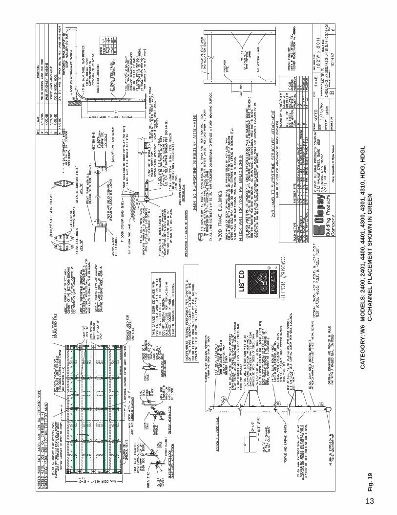
2400/2401/4400/ W6 16'4"-18'2" 6" C-Channel Figure 19 / Yes No Yes No Figure 114401/4300/4301/ (Double Car) 1 per section 1014874310/HDG/HDGL
73/75/84A/94 W7 9'2"-16'2" 6" C-Channel Figure 20 / Yes No Yes No Figure 11(Double Car) 1 per section 101309
84A/94** W8 9'2"-16'2" 6" C-Channel Figure 21A-B Yes No Yes Yes Figure 11(Double Car) 1 per section 101300
2400/2401/4400/ W8 9'2"-16'2" 6" C-Channel Figure 22A-D Yes Yes No No Figure 114401/4300/4301/ (Double Car) 1 per section 1014884310/HDG/HDGL
* The bottom section is considered the first section, the second section from the bottom is considered the second section, etc.**Doors sometimes called 84AD and 94D.
3
Fig. 2
Fig. 3
Top Section of Door
AdjustableTop Bracket
8- 1/4" x 3/4"Self-TappingScrews(Green)
UNTHREADED THREADED
Pushnut
Fig. 4
RollerSupport Brackets
BottomBracket
DoubleEnd Stile
Long Stem Roller
4- 1/4" x 5/8"Sheet MetalScrews
DOUBLE TOP BRACKET INSTALLATION
THREADED & UNTHREADED ROLLERS
BRACKET INSTALLATION
7/16" Flange Nut
Top Bracket Installation
Double Top BracketIf your door has double end hinges then installtwo top brackets instead of one. Double topbrackets are installed side-by-side. Each Topbracket is installed exactly like a single topbracket. Once installed, the slide adjustmentsmust be aligned so that the long stem roller canbe inserted through both slide adjustments. (FIG. 2)
NOTE: Rollers with pushnuts or threaded rollerswith flange nuts may be used on windload doors.(FIG. 3)
To install the pushnut roller simply slide the rollerinto the hinges and after the track is installed,slide the pushnut on the rod of the roller until it iswithin a 1/8" to 1/4" of the hinge.
To install a threaded roller proceed as before andafter track is installed, thread the 7/16" flange nuton the rod until the 7/16" flange nut is within 1/8" to1/4" of the hinge.
Bottom Bracket Installation
Double Bottom BracketPosition bottom bracket as shown in MANUAL.Align the roller support bracket tube with the rollerholes in the bottom bracket, so that the long stemroller can be inserted through the bottom bracketand roller support bracket. Attach with (2) 1/4" x3/4" self-tapping screws. (FIG. 4)
NOTE: A second roller support bracket can beused as a shim to allow the long stem roller freemovement.
Double End Stile
Holes MayNot Line Up
Long StemRoller ThroughBoth Brackets
- or -
2- 1/4" x 3/4"Self-TappingScrews (Green)
4
Fig. 6
Fig. 7
41/4" x 3/4"Self-TappingScrews (Green)To ReplaceCorrespondingSheet MetalScrews
DrillHoles
Hinge
End Stile
Strut
Strap
15/16"ClearanceHole
End Stile
C-Channel
41/4" x 3/4"Self-TappingScrews (Green)
SCREW PLACEMENT
#2 Hinge
DoubleEnd Stile
Long StemRollerThroughBoth Hinges
Fig. 5
End Hinge Installation
Double End Hinges14 Gauge hinges are used at end stile locations(for more detail, see MANUAL). Place two endhinges on the double end stile as shown. Attacheach end hinge to end stile by inserting (4) #14 x5/8" sheet metal screws through the prepunchedholes in the end stile. Insert (2) 1/4" x 3/4" self-tapping screws per hinge as shown. (You mayhave to pilot drill 5/32" holes before installing self-tapping screws.) (FIG. 5)
Strut / C-Channel Attachment
Depending on the Model and windload categoryof your door, different reinforcements will be used.Consult the accompanying drawing outlined inTable 2 to see the required reinforcement type(strut or c-channel) and placement.
Strut Installation
Double Hinge Strut Attachment
To attach strut, position the strut on the door. Drillone 5/32" hole at the top and one 5/32" hole at thebottom of the strut at all stile locations. Attachstrut to door section with 1/4" x 3/4" self-tappingscrews through drilled holes. (FIG. 6)
Note that the strut overlaps the hinge leafs.
C-Channel Installation
Pan Door C-Channel Attachment
Position the C-channel on the door. Attach C-channel to door section with (1) 1/4" x 3/4" self-tapping screws through drilled holes at each stilelocation. Then attach one C-channel strap atcenter hinge and end hinge locations (See Figures14-22). C-Channel straps are attached to the C-channel with (1) 1/4" x 3/4" self-tapping screws, andattached to the door with (2) 1/4" x 3/4" self-tappingscrews. (FIG. 7)
DOUBLE END HINGE INSTALLATION
C-CHANNEL INSTALLATION
DOUBLE HINGE STRUT INSTALLATION
81/4" x 5/8"Sheet MetalScrews
41/4" x 3/4"Self-TappingScrew (Green)
5
41/4" x 5/8"Sheet MetalScrew41/4" x 3/4"Self-TappingScrew (Green)
Backer Plate
Double SkinDoor
Double StickTape Peel Off
Paper
Fig. 8
EPS Door C-Channel AttachmentBefore attaching C-channel, a backer plate shouldbe placed behind where the C-channel is to beinstalled. Position the C-channel on the door.Attach C-channel to door section with (1) 1/4" x 3/4"self-tapping screws through drilled holes at eachhinge location. Then attach one C-channel strapat center hinge and end hinge locations. (SeeFigures 14-22).C-Channel straps are attached to the C-channelwith (1) 1/4" x 3/4" self-tapping screw, and attachedto the door with (2) 1/4" x 3/4" self-tapping screws.(FIG. 8 and 9)
(For Sandwich Doors Only)C-CHANNEL INSTALLATION WITH
BACKER PLATE
C-Channel ToBe AttachedTo BackerPlate.
Existing Holes(4) Shown
81/4" x 3/4"Self-TappingScrew (Green)
End StileStrap
Fig. 9
15/16"ClearanceHole
Strap
DOUBLE END STILE C-CHANNEL ATTACHMENT
Jamb Configuration
The design of the supporting structuralelements (i.e. door jamb) shall be theresponsibility of the professional of recordfor the building or structure and in accordancewith current building codes for the loads listedon the technical drawing (attached) for thespecific model.
It is also important that the vertical 2 x 6 woodjambs are attached to the supporting structurein a method that is sufficient to transfer theloads exerted by the wind pressures. Somesuggested vertical jamb attachment methodsare included in the drawings. (FIG. 13 to 22)
C-Channel
6
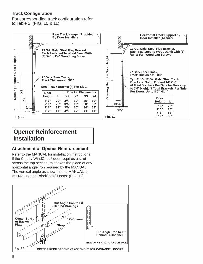
Rear Track Hanger (ProvidedBy Door Installer)
13 GA. Galv. Steel Flag Bracket.Each Fastened To Wood Jamb With(3) 5/16" x 15/8" Wood Lag Screw
Horizontal Track Support byDoor Installer (To Suit)
13 Ga. Galv. Steel Flag Bracket.Each Fastened to Wood Jamb with (3)5/16" x 15/8" Wood Lag Screws
2" Galv. Steel Track,Track Thickness: .083"Typ. 21/2"x 12 Ga. Galv. Steel TrackBrackets. Not to Exceed 14" O.C.(6 Total Brackets Per Side for Doors upto 7'0" High). (7 Total Brackets Per SideFor Doors Up to 8'0" High)
Attachment of Opener ReinforcementRefer to the MANUAL for installation instructions.If the Clopay WindCode® door requires a strutacross the top section, this takes the place of anyhorizontal angle iron required by the MANUAL.The vertical angle as shown in the MANUAL isstill required on WindCode® Doors. (FIG. 12)