AD-A2 68 283 DTIC SELECTE \ \ \AUG2 3 19931 N00014-90-JI913 C D Progress Report STUDY OF BRIGHTNESS AND CURRENT LIMITATIONS IN INTENSE CHARGED PARTICLE BEAMS For the period July 1, 1992 - June 30, 1993 Submitted to Office of Naval Research Submitted by Laboratory for Plasma Research University of Maryland, College Park Principal Investigators M. Reiser and S. Guharay [ D7-1 TAT i•- Arpror¢ = ut ,sQa 185 ,93-17486 UNIVERSITY OF MARYLAND LABORATORY FOR PLASMA RESEARCH COLLEGE PARK. MARYLAND 20742-3511 -
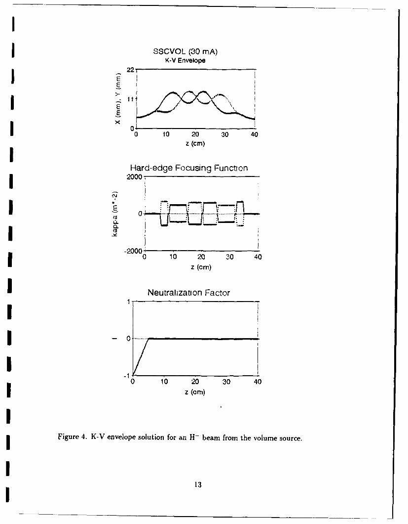
Figure 4. K-V envelope solution for an H- beam from the volume source.
13
I
I100! 100!I IO0 O0
E oi o
-I000 -I00-1I0 0 10 -10 0 10
X (mm) X (min.
100, 100,
q- a
F . _ _ i at i-100J -100I-10 0 10 -10 0 10
Y (mm)Y(rm
(a) (b)
IiII
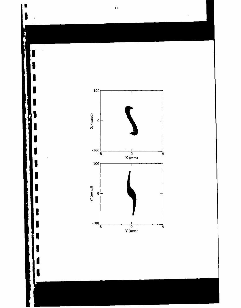
Figure 5. (a) Particle distribution at the input of the ESQ LEBT; (b) particle distribution
at the output of the ESQ LEBT.
14
pdec231129.asf run Thu Aug 6 15:01:59 1992II
150
Ii
100
I -50
C 0 ---0
-50
U- -100
-0.5 0.0 0.5 1.0 1.5
position (cm)
I• Figure 6. Contour plots of the beam from the SSC magnetron source.
15I
mI
m 25
I 20
-- 10
5
*1
2000
-2000-
0 10 20 30z(cm)
Figure 7. K-V envelope solution for an 11-beam from the magnetron source.
16
I r~..~t.,(KV) 0 ,..100-
a-* x
I -100'-5 0 5 -5 0 5
X (mm) X (mm)
100.E Of
I0-
I-100'
* 5 0 5 -5 05Y (mm) Y(mm)
Figure 8. Particle distribution from modified PARMILA.
I17I
I i t i I K t ct -11p t ~ i t I Si II I '-\ t(7 'p M
II
I
III g
I
II
I
I
Ic
I Figure 10. LEBT test facility at Maryland
Fiur 11., Manern orc omoensofth es -acltya Mrlad
I20
IBII
I Fgr I anto orecmoet ftets aiiya ayad
I2
IIII,
I
I Figure 12: Triangulated ESQ Lens
II 0J.02
"I- 0.01
--50 -25 0 25 50z (mm)
Figure 13: ESQ Lens Focusing Function
21
I
STUDY OF BRIGHTNESS AND CURRENT LIMITATIONS IN INTENSE
CHARGED PARTICLE BEAMSIM. Reiser and S. Guharay, University of MarylandI
PRESENTATIONS, PUBLICATIONS, AND INVITED TALKS
1. S.K. Guharay, C.K. Allen, M. Reiser, K. Saadatmand, and C.R. Chang, "Study of
emittance growth and its control for a low-energy H- beam transport system," AIP
Conference Proceedings on Production and Neutralization of Negative Ions and Beams
(to be published).
I 2. S.K. Guharay, C.K. Allen, and M. Reiser, "ESQ focusing for an intense, high-brightness
H- beam: Emittance growth and its remedy," Proceedings of the 9th International
Conference on High Power Particle Beams (to be published).
3. C.K. Allen, S.K. Guharay, and M. Reiser, "Solution of LAPLACE's equation by the
method of moments with application to charged particle transfers," AlP Conference
I Proceedings on the Computational Accelerator Physics (to be published).
4. S.K. Guharay, C.K. Allen, M. Reiser, K. Saadatmand, and C.R. Chang, "An ESQ lens
system for low energy beam transport experiments on the SSC test stand." Proceedings
of the 1993 Particle Accelerator Conference, May 17-20, 1993, Washington, DC (to be
published).
- 5. S.K. Guharay, C.K. Allen, M. Reiser, K. Saadatmand, and C.R. Chang, "A compact
ESQ system for transport and focusing of H- beam from ion source to RFQ," 1992
LINAC Conference Proceedings, vol. 1, p. 338.
I 6. S.K. Guharay, C.K. Allen, and M. Reiser, "Study of beam dynamics and desing of
a low energy beam transport for intense, high-brightness H- beams," submitted to
Nuclear Instruments and Methods in Physics Research.
22
I
7. C.K. Allen, S.K. Guharay, and M. Reiser, "A moment method Laplace solver for
low energy beam transport codes," Proceedings of Particle Accelerator Conference,
Washington, DC (1993) (to appear).
8. S.K. Guharay, C.K. Allen, M. Reiser, "A compact, precision electrostatic quadrupole
lens system for high-brightness ion beam transport and focusing," SPIE Conf. on
Charged Particle Optics, San Diego, CA, July 15, 1993.
2
1
IIIII
I2
Paper published in AIP Conference Proceedings 287
STUDY OF EMITTANCE GROWTH AND ITS CONTROL FORA LOW ENERGY H- BEAM TRANSPORT SYSTEM"
i S. K. Guharay. C. K. Allen. M. ReiserUniversity of Maryland. College Park, .\ID. 20742
K. Saadatmand. C. R. Chang
Superconducting Super Collider Laboratory. Dallas. Texas 75237
I ABSTRACT
A compact 6-lens electrostatic quadrupole lens system in conjunction with aI short, single einzel lens section has been developed with the aim of transporting a
30 mA, 35 kV H- beam (normalized beam brightness of about 10"1 A/(m-rad)2 )over a length of about 30 cm and focusing it into an RFQ. The effect of a neutralbackground gas on the measurements of the beam from the ion source is studiedin order to evaluate reliably the input beam parameters for the lens design. Thebeam dynamics calculations have been made using simulation codes for typical H-beam parameters from two different ion sources: a magnetron type and a volumesource type. The simulation results show a relatively modest emittance growth.that is within about 50-60% even in the case of an input beam with very smallbeam radius 1.1 mm) and very large divergence (72 mrad).
I INTRODUCTION
Over the past few years our research has been primarily focused on simulationstudies of charged-particle beam dynamics with the aim of developing an effi-cient low-energy beam transport (LEBT) system for intense, high-brightness H-beams. While dealing with the problem of design and development of an LEBT.
we encountered several problems of practical interest. One of the puzzling issues
is related to the assumption of input beam parameters. Often. the beam param-eters are measured at a certain distance, typically -- 10 cm. downstream from theextraction aperture of the. source. This leads to some uncertainty in predictingbeam parameters at the extraction point as this information is required to definethe input beam parameters in designing a LEBT. Second, the beam parametersat the extraction aperture depend very much on the mechanism of ion sourceoperation and the extraction optics. It is thus of practical interest to adapt anLEBT scheme which may function reasonably well for a certain range of the input
beam parameters. Such a system is less susceptible to failure in th,. event the
source parameters drift to a certain extent: this situation is encountered quitecommonly in experiments with ion sources. Third. in the injectors of high-energyaccelerators a good buffer space. -20 - :30 cm. between the ion source and the first
I stage of acceleration. commonly an RFQ (radio-frequency quadrupole), is desired
"Supported by ONR/SDIO and DoE
II
Ias it offers some practical advantages in terms of clean operation of the RFQ andflexibility in achieving satisfactory transformation of beam parameters.
The present article addresses the aforementioned problems when widely dif-ferent beam parameters are used as input conditions. Special considerations aregiven to meet the matching condition dictated by the acceptance ellipse parame-ters of the RFQ in the Superconducting Super Collider (SSC).'
INPUT BEAM PARAMETERS AND THE ROLE OF NEUTRALIZINGBACKGROUND
Beam characterization experiments were done on the SSC test stand with H-beams from both magnetron and volume ion sources. In this article, we willmainly deal with the magnetron beam parameters; some analysis is done using Itypical beam parameters of the Brookhaven National Laboratory (BNL) volumesource. Sadaatmand et al. reported some recent results on the characteristicsof H- beams from the SSCL volume source2 ; we plan to use these results in thefuture to study beam dynamics in the context of our LEBT system.
Figure I shows the phase-space distribution of the beam particles, when theernittance scanner slit was located at 11.75 cm downstream from the extractionslit of the source. Using the best fit to the data by an ellipse, the Twiss parameterswere determined. The valu'es of the beam size in the two orthogonal directions(X and Y) and the respective slopes (X' and Y' ) were obtained as: X = 14.5mm. X' = 132.2 mrad: Y = 18.9 mm. Y' = 175.4 mrad. In order to estimatethe beam parameters at the extraction slit, a linear beam optics code is used.This code takes the above values of the beam parameters at z = 11.73 cm asinput, and it integrates the Kapchinskij-Vladimirskij (K-V) envelope equationsbackwards towards the extraction aperture. The background gas may have an Iimportant role in this analysis, particularly in relation to the evaluation of thespace-charge neutralization factor f.v which enters in the calculation of the space-charge force. Various spatial profiles of f.v have been considered: the results arerather insensitive to the variation of fv . We have shown two cases in Fig. 2: (a)fN = 0, and (b) fN = 1.0 at the extraction aperture and it falls off exponentiallyafterwards. From this analysis we predict a beam radius of 1.1 mm and slope of72 mrad at the extraction slit.
In order to further understand the role of a neutralizing background on mea-surements of the spatial evolution of beam parameters, we studied three cases ofpractical relevance: (a) a 30 mA, 35 kV beam with a beam radius of 1.1 mmand beam divergence of 72 mrad, representing a magnetron source as describedabove, (b) a 30 mA. 35 kV beam with a beam radius of 5.6 mm and near-parallelextraction. representing a BNL volume source,3 and (c) for higher current - 120
mA. 30 kV beam with a beam radius of 2 mm and near-parallel extraction. Theeffective emittance values in the three cases are almost similar. the range being5.0 - 6.6 x iO- m-rad. Figure 3 shows the spatial evolution of the beam envelopeswhen several different values of the space-charge neutralization factor (f.v = 0.
II
I,.0
-, _ _ _ _ _ _ _ _ _ _ I _ _ _ _ _ _ _ "
100
CA 0* 1.0 0.$
P=oU~n 1CM)
Figure 1: Phase-space distribution of H- beam from the SSCL magnetron source.The measurements were made at 11.75 cm downstream from the extraction aper-ture.
1 0.5, 1.0. and 1.04) were assumed. As a typical example. fv is taken constant, C,up to z = 10 cm. and then it linearly drops to zero at z = 15 cm. The resultssuggest that the space-charge neutralization factor significantly changes the beamenvelope for the cases (b) and (c), and that the effect is not as strong in the case(a). Comparing the various terms in the K-V envelope equations, we note thatthe ratio of the space charge force to the emittance force. Ka2 /E2 . is initially (atz = 0) much larger than I in the cases (b) and (c); while this ratio is close toI in the case (a). (K = 2AI/oI'-3 is the generalized beam perveance. 16 is thebeam current. Io is the characteristic current (3.1 x 10' A for H- beam), 3 = v/c,"-Y = ( - 32 ')-/2. a is the initial beam radius. and f is the effective beam emit-tance.) In the cases where the space-charge force is the most dominant factor.it may be postulated that the aforementioned method to estimate initial beamparameters may introduce some ambiguity, unless a good understanding of thegas dynamics is achieved and is incorporated properly in the analysis.
SIMULATION OF BEAM DYNAMICS THROUGH A LEBT SYSTEM
I (a) H- Beam from the SSC Magnetron SourceA proto-type ESQ LEBT system has been developed in-house at Maryland.
and the system has been described in detail elsewhere. 4 Figure 4 shows the geom-etry of the LEBT system. In a previous article.' we reported that the apertureof the lenses in the proto-type ESQ LEBT system needs to be increased by a fac-tor of two to accommodate the large excursion of the SSC magnetron H- beam.Further details of the beam dynamics are presented here. where the ESQ lens
I I II
III
to
20_____I
to
0 412
z(cm)
IFigure 2: K-V envelope solution for H- beam propagating over the drift space be-tween the extraction aperture of the magnetron source and the slit of the emittancediagnostic. Here z = 0 is considered as the location of the slit of the emittancediagnostic: the beam envelope is calculated backward toward the extraction slitwhich is here at z = 11.75 cm. Space-charge neutralization factor, fv, is takenas: (a) zero (upper figure), and (b) exponentially falling with the peak value as1.0 at z = 11.75 cm (lower figure). The inset in the lower figure shows the spatialprofile of fN.
IIIII
I2
I - - -'•
Zo
X toI
n to 20 3
b c re , I =0 I,.,,, ba vt V =.35 M initial ba ri a = 1.1
I
=I56m.rl= 20: (c) 16 = 12 - , 3 20m.r a=0 h
I i : 5.
- .. . ....-
-- / .- ., ...
l O2 0 I -
z(cm)
I Figure 3: Spatial evolution of the beam envelope for three different cases: (a)beam current I = ,30 mA, beam voltage V = ;35 kV, initial beam radius a = 1.1mm, initial beam divergence r'Ir=, =72 mrad: (b) lb and V6 are same as in (a), a
I = .5.6 mm. r',•= 0: (c) '6 = 120 mA, l'• = 310 kV, a = 2.0 mm. r'r•-0. The
bottom figure shows the nature of the assumed space-charge neutralization factor
fN. The four different curves in each figure correspond to different values of theconstant C. Going from the leftmost side of each figure. solid line: C = 0. nextdashed line: C = 0.5, dotted line: C = 1.0. next dashed line: C = 1.04.
II,
I
ELECTRODE GROUND PLATE
\ //
a I
CERAMIC SALL SINGLE PIECEEINZEL LENS MODULE
Figure 4: The LEBT system. sc~ . I
parameters. especially the voltages, are further optimized and also the design ofthe end section of the LEBT consisting of a short einzel lens is further developed.
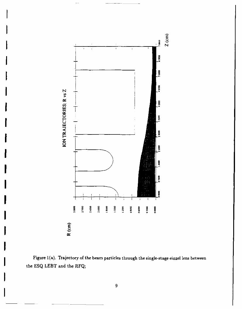
Figure 5 shows the most optimized envelope solution that we have obtaineduntil now after a number of iterations of our numerical scheme.' The maximum 3beam excursion in one plane (about 17 mm) is found significantly larger thanin the other orthogonal plane (about 10 umm). Initially we obtained an envelopesolution with symmetric beam excursions in both X and Y-planes: however, theemittance growth was higher in this situation. This is an artifact of nonlinearbeam dynamics. As a rule of thumb. nonlinear effects, which contribute to thedistortion of the beam optics and thus enhance the beam emittance. are not Iimportant if the beam does not occupy more than about 75% of the quadrupoleaperture. Hence it is clear from Fig. 5 that the emittance growth should primarilyoccur in the X-plane. The phase-space distribution of the particles, obtainedfrom the modified PARMILA code (a 2'-D code) is shown in Fig. 6, the resultsconform to the physical picture revealed in Fig. 5. Here a beam current of about25 mA is transported. The remaining part of the 30 mA input beam currentcontributes enormously (more than 300%) to the emittance growth. This group ofparticles, which behaves like a "halo" and occupies a large phase-space boundary,is eliminated by a beam scraper. The emittance growth for about 25 mA of beamcurrent is estimated to be about 50% assuming a K-V type distribution of theinput beam (Fig. 6); the estimated emittance growth is about 60% for a Gaussian Iinput beam as shown in Fig. 7.
From the modified PARMILA results shown in Fig. 6 it is estimated that theoutput beam parameters at 6 mm downstream from the last lens of the ESQ LEBT
II
I
I / I- -.
I =.
I 0 +0 lIlll IlI
I Figure 5: Envelope solution for the ESQ LEBT section using SSCL magnetronbeam parameters. A hard-edge type external focusing function ,c(z), as shown inthe bottom figure. is assumed.
-100,
"1005 0 5 -5 0 5
100,
I 210-5 0 5 -5 0 5
Y (mm, Y (mini
Figure 6: Modified PARMILA results on phase-space distribution of particlesthrough the ESQ LEBT section (magnetron beam case). Left-side figure: inputbeam distribution (K-V type): right-side figure: output beam.
I150.
-150',-'0 0 10 -10 0 'C
-- I ' I
110 0 10 10 0 10
* I I
Y ( rma! Y (nMMr
Figure 7: Modified PARMILA results for the same case as in Fig. 6 using aGaussian input beam distribution.
are: X = 4.68 mm. Y = 4.38 mm. X' = -49 mrad. and Y' = -48 mrad. Thisbeam is given as input to a short. single einzel lens section cascaded to the ESQ.LEBT. The einzel lens is composed of three electrodes as shown in Fig. 8 (topfigure) - the first and the third electrodes are at ground potential. and the center Ielectrode is at a high negative potential close to the beam voltage. In our experi-mental configuration. the two grounded electrodes of the einzel lens are made ascommon elements. respectively, with the last shunt piate of the ESQ LEBT andthe front wall of the RFQ. The output from the einzel lens is determined usingthe SNOW-2D code. The output beam distribution in Fig. S shows the results Iat a downstream location of 1.0 cm from the front of the RFQ's ground wall: aneffective ellipse representing the output beam in Fig. 6 is given as input here.The beam parameters at this location match well with the acceptance ellipse ofthe RFQ. However, if the input vane of the RFQ is located further away, the lensparameters need to be adjusted. It may be noted that the einzei lens section doesnot introduce any emittance growth. Hence the overall emittance growth in theentire LEBT channel is about 50%.
(b) H- Beam from a Volume SourceThe beam parameters of BNL volume source3 are used in this case. The proto-
type ESQ LEBT system developed at Maryland is well suited to transport such Ibeams. Figure 9 shows the K-V envelope solution; we have aimed here to obtaina beam convergence of about -20 mrad at the output as the final focusing willbe done by an einzel lens. I
The phase-space distribution of particles in the input and output beams forthe ESQ LEBT section is shown in Fig. 10. The output beam is almost free from
II
II
R CMI
2.100
I K-
-100-I,,0
I .
I -
I~ 0_________
-100
I 0 5
i ~r (ram)
I Figure 8: SNOW-2D results for the einzel lens section using the output beam from
the ESQ LEBT (magnetron case). Top figure: beam envelope through the lens.Middle figure: phase-space plot of the input beam. Bottom figure: phase-spaceI plot of the output beam.
I!E
I!
I
122
-o~ I I
- - d I
Figure 9: Enveiope solution for the ESQ LEBT section using volume source pa-
ramneters.
distortions, and the emnittance growth is insignificant. The SNOW-2D code resultsshowing the behavior of the beam particles as they move from the end of the ESQLEBT section and are being focused by the einzel lens, are shown in Fig. 11. Theoutput beam distribution is taken here at a distance of 1.0 cm downstream from Ithe front end of the third electrode (at ground potential) in the einzel lens: thethird electrode should be considered as the front wall of the RFQ in reality. TheI
emittance growth in the entire LEBT channel is very small. < 15%, here.I
CONCLUSIONS
One of the major points in this article is the simulation analysis to estimatebeam parameters at the extraction aperture from the measured data at a certaindistance away, typically about 10 cm downstream. It is noted that an uncertaintyIin the analysis generally occurs due to the lack of precise knowledge about theneutralizing gas background. Thle importance of this issue depends significantly onthe initial conditions of the beam, primarily the ratio of K'a2/•2 . For K'a2/• 2 I,close to the extraction aperture, as in the case of the SSC magnetron beam, thespatial evolution of the beam envelope over a distance of about 10 cm is quite Iinsensitive to the variation of the space-charge neutralization factor, f~v. Thebeam envelope is found to be significantly affected by the variation of fIN forKa2 /• 2 3> I: examples are given for a 30 mA volume source beam and a situationIwith large beam current (120 mA).
The beam dynamics through a LEBT system, comprising of 6-ESQ lensesand one einzel lens, have been studied in detail using simulation codes. The
I
009S.. . . . . . . . . . . . . . . . . . . . . . . . .m m a m m m u m u n o nl |7
I 100,i lOi -q-
I ,-100"-1001 0 10 .1-0 0 10IX (MMI X (mnns
100,
I -100-10 0 10 -10 0 10
Y (MMI~ Y (Mmin
i Figure 10: Modified PARMILA results on phase-space distribution of particlesthrough the ESQ LEBT section (volume source case). Left-side figure: inputbeam distribution (K-V type): right-side figure: output beam.
i 100o
I10 1 0 1 0
100 r (mm)
E 01
-100o-1000 0 10
r (mm)
Figure 11: SNO\V-2D results for the einzel lens section using the output beamfrom the ESQ LEBT (volume source case). Top figure: phase-space plot of theinput beam. Bottom figure: phase-space plot of the output beam.
II
Ianalyses have been done using two widely different input beam parameters. andthe LEBT systems have been designed accordingly. The present LEBT system isvery compact. and it has a good tunability to control the emittance growth. Inthe case of a :30 mA. :3.5 kV SSC magnetron beam when the input beam radius Iis taken as 1.1 mm and the beam divergence is 72 mrad. the beam into the RFQhas an emit~ance growth of about 50 to 60%. Here a scraper in the ESQ LEBTsystem is used to deliver 25 mA of output beam current. which appears to be thenominal SSC injector beam current. This part of the beam conforms to a goodcore geometry, and hence it suffers less due to aberrations. While dealing witha larger beam (5.6 mmn in radius and near-parallel extraction) corresponding tothe BNL volume source case. the LEBT svstem is shown to behave verv nicely,and the full beam (30 mA) can be matched into the RFQ with practically noemittance growth.
The present LEBT system has several strong features. The transport sectionof about 30 cm length creates a good buffer space between the ion source and Ithe RFQ. It thus insures a clean operation of the RFQ. Several tuning knobsallow us to handle some variation of the input beam characteristics and maintainan acceptable level of emittance growth. Anderson et al. reported intriguingexperimental results with similar LEBT systems based on a combination of ESQlenses and one einzei. lens (referred as a ring lens in their paper); near-parallel inputbeams with brightness about an order of magnitude lower than in the presentlyinvestigated cases were considered there.
A comment is made in the context of the present experimental effort. Thecurrent LEBT svstem will satisfv the RFQ's matching condition approximatelyI cm downstream from the RFQ aperture. With intense, high-brightness beamsthe problem of matching will be formidable if the drift space between the end of Ithe LEBT and the RFQ entrance is too large: the emittance growth may need tobe sacrificed enormously.
REFERENCES
1. T. S. Bhatia. J. H. Billen. A. Cucchetti. F. W. Guy, G. Neuschaefer. L.M. IYoung, "Beam Dynamics Design of an RFQ for the SSC Laboratory", Proc.IEEE Particle Accelerator Conf.. San Francisco. CA. May 6-9. 1991. p. 18 8 4 .
2. K. Saadatmand. J. E. Hebert. N. C. Okay, "RF Volume H- Ion Source forthe Superconducting Super Collider", these proceedings.
3. J. G. Alessi, Private communication.
4. S. K. Guharay, C. K. Allen. M. Reiser. V. Yun. "Low Energy 11- Beam iTransport Using an Electrostatic Quadrupole Focusing System". Proc. Par-ticle Accelerator Conf.. San Francisco. CA. May 6-9. 1991. p. 1961.
II
I 5. S. K. Guharay. C. K. Allen. M. Reiser, K. Saadatmand. C. R. Chang, "ACompact ESQ System for Transport and Focusing of H- Beam from IonSource to RFQ" Proc. Linear Accelerator Conf.. Ottawa. Canada. August24 - 2S. 1992. p. :338.
6. S. K. Guharay, C. K. Allen. M. Reiser. P. G. O'Shea. 'Experimental Studyof a High-Brightness H- Beam and Its Transport Through an ESQ FocusingSystem", Intense Microwave and Particle Beams III, SPIE vol. 1629. 421(1992); S. K. Guharay, C. K. Allen. M. Reiser. "Electrostatic Focusing andRFQ Matching System for a Low Energy H Beam", Intense Microwave andParticle Beams 1I. SPIE vol. 1407, 610 (1991).
I 7. 0. A. Anderson. L. Soroka, J. W. Kwan, R. P. Wells. "Application of Elec-trostatic LEBT to High Energy Accelerators" Proc. 2nd European ParticleAccelerator Conf.. Nice. June 12-16, 1990.
IIIIIIIIIIII
r Beams '92 Conierence
ESQ FOCUSING FOR AN INTENSE, HIGH-BRIGHTNESS H- BEAM:EMITTANCE GROWTH AND ITS REMEDY
S. K. Guharay, C. K. Allen. &f. Re;ser
University of Maryland, College Park, MD 20742 U.S.A.
AbstractA simple, novel electrostatic quadrupole (ESQ) lens system has been developed to transport
and focus an intense, high-brightness (normalized beam brightness 0- "01 A/M 2 rad 2 ) H-beam. The physics of emittance growth in the ESQ transport system is studied in detail bycomputer simulation of beam dynamics, when the influence of various factors, e.g., input beamparamneters, aberrations, misalignments, etc. has been examined. Possible methods to controlthe emittance growth have been suggested.
I. IntroductionAlthough there has been a significant progress in the physics and technology of high-energy
accelerators, many new areas of research are still emerging primarily due to a variety of needs ofthe new accelerators and its applications, e.g., exploration of fundamental particles, space defenseby antiballistic neutral particle beams, radio-active waste transmutation. etc. It is recognized thata very good quality beam, defined by its emittance, is required in a high-energy accelerator. This isparticularly true in the case of new accelerators. e.g., the Superconducting Super Collider.' wherethe emittance budget through the accelerator chain is very tight due to the stringent requirement forhigh luminosity (10 3 cm-2s-') of the colliding beams. In this pursuit this group at the Universityof Maryland has been engaged over the last several years in the development of an efficient low-energy beam transport (LEBT) section. This unit lies between an ion source and the first stageof acceleration of the beam (e.g., a radio-frequency quadrupole (RFQ) accelerator) and plays animportant role in accelerator research.
The LEBT acts as a phase transformer of the beam from the ion source so that a normallydiverging beam from an ion source can be focused with a high convergence angle (- -100 mrad)into an RFQ. Also. the LEBT creates a buffer space between the ion source and the RFQ; thisreduces the possibility of any contamination of the RFQ due to cesium or gas load from the ionsource. In spite of an exhaustive body of literature in this field, the state-of-art is not satisfactory.So far the major experimental efforts on LEBT systems in accelerators have been made withIsolenoidal lenses. or magnetic quadrupoles 3 supplemented 1y gas focusing. The design of suchsystems has been mainly empirical and control parameters are not known apriori with sufficientaccuracy. Significant emittance growth of the beam is noted in this scheme. Other schemes deal withelectrostatic lenses (einzei lens.' electrostatic quadrupole lens. 5 .6 helical electrostatic quadrupoiclens7) or radio-frequency quadrupole lens.3 Although such alternate schemes have been tested insome experiments, no experimental effort has been made so far in regard to transporting andfocusing intense, high-brightness H- beams (typically, beam current of 30 mA. beam voltage of 3.5kV, normalized brightness , 10" A/m 2 rad2 ). It is important to focus our attention to such beamsas they are relevant to the potential applications of modern accelerators.
The present article delineates the problem of H- beam transport and its matching to an RFQusing a novel 6-lens electrostatic quadrupole (ESQ) system as an LLBT. The main emphasis here isto understand the physics of emittance growth in an ESQ transport system and the possible waysto mitigate the problem. In the past the ESQ LEBT system was used very successfully to transportH- beams;6 however, the beam perveance was much lower there. Here we consider a highly space-charge dominated, high-brightness beam (beam perveance K = 0.003 and normalized brightness
-i .\/m 2 ra&"). It is quite a challenging task to transport sucn beams over a certain distance ana
focus it into an RFQ without any significant emittance dilution. The design is based on detailedcomputer simulation of beam dynamics through the transport section. The computer predictions
regarding performance of the LEBT system are analyzed in the context of beam parameters of two
particular types of H- ion sources - Penning-Dudnikov source as used in the BEAR experiment.3 Uand a volume ionization source of Brookhaven National Laboratory.9 These two types of sourcesare particularly suitable to obtain high-brightness H- beams.' 0 In our previous articles. H- beams
from a Penning-Dudnikov source were mainly considered. Here, the emphasis is on the transportof H- beams from a volume source. We have also addressed the issue of sensitivity of the beam
parameters due to misalignments. Finally, the problem of matching the H- beam to an RFQ is
discussed.
II. Beam Dynamics through the ESQ LEBT
The design procedure as reported earlier 11 involves a sequence of computer code analysis: {i) IA linear beam optics code integrates the K-V envelope equations and generates the basic geo-
metrical parameters of the lens system. (ii) A 3-D LAPLACE solver calculates the equipotentials
and evaluates the fringe-field matrices as suggested by Matsuda and Woilnik.12 (iii) A modified lPARMILA code13 uses input from the above two steps and evaluates the beam parameters (beam,ize. emittance growth. etc.). This scheme led us to choose a combination of six ESQ lens systemto transport H- beams over a distance of 30 cm and to provide a moderate convergence ( - -301
mrad) at the end. The technical details of the LEBT svstem and some rpsults on the computercode predictions of beam cdaracteri- tics have been given earlier." The essential points to note fromi
our previous articles are:
1. .\ unique feature in the desian of the ESQ LEBT system is that the entire svstem is seif-aligned mechanically. [his demands high precision in the fabrication of the components and
their assembly. On the other hand. it eliminates the usually tedious alignment job in the
,x periment.
"2. The performance of the ESQ LEBT has been examined using beam parameters of a Penning-
Dudnikov source. Some assumptions of the input beam (normalized brightness = A x 101m.\/m-rad'. divrerence at full beam radius of I o-'n = 20 mnrad) are made on the basis oh
analysis of the emittance data at z = 10.6 cm from the extraction hilt." The output beam t
from the ESQ LEBT is found converging (-, -25 mrad). and it shows an emittance growth by Iit factor of about 1.8 assuming a K-V type distribution of the beam. The eliittance growth
is identified as due mainly to hromatic aberrations.
The above analysis has been carried out further. Figure l(a) shows the evolution of rms nor-malized emittance through the ESQ transport channel. The enhancement of emittance occurs
essentially in the second and fifth lenses, when the amplitude of the beam envelope grows to more
than ,•O% of the quadrupole aperture. The beam particles residing in the outer part of the enve-
lope are responsible for the emittance growth. and these particles can be rejected by suitable ,lse
of the ground plates between the adjacent ESQ lenses (Fig. 10 in ref. 11) as beam scrapers. F-,%o
beam scrapers are inserted, one in front of the second lens and the other in front of the fifth lens.
Figure l(b) shows the evolution of emittance through the ESQ LEBT when 10% of beam particles Iare scraped out. The emittance growth is a factor of 1.. here. This is an efficient % ay to deliver U
__ I
I an almost emittance-preserved beam to an RFQ. The above analysis has been carried out usingtypical parameters of H- beams from a volume ionization source, here a BNL-type. Usually thebeam from such sources has lower current density compared to, say, the Penning-Dudnikov case.hence. a larger extraction slit (radius of extraction slit = 5.6 mm here as opposed to a radius ofI mm in the Penning-Dudnikov case) is used to draw the same amount of current in the case ofvolume sources. Also the beam divergence at the extraction slit can be very small: almost a parallelbeam car. be extracted from the source. The estimated normalized brightness of this beam is about3 x 10'°A/mrad2 : all other parameters have been given earlier."1
Figure 2 shows the modified PARMILA results on distribution of the beam particles correspond-ing to an H- beam from the volume source. Here the parameters corresponding to a 4 times rmsellipse, constructed by including 90% of the beam particles at the output of the ESQ LEBT, are:.YI,. = 3.3 mm. Yn,,m. = 2.7 mm, (X. )' = -13.5 mrad, (Ym.)' = -14.9 mrad. The maximumvoltage on the ESQ lenses was 4.7 kV. The emittance growth of the beam is negligibly small,1%. This result suggests that the characteristics of the input beam are very crucial to the issue of*'mittance growth in a transpor. system - - a parallel input beam is desirable.
The sensitivity of output beam parameters with variation of beam voltage, beam current. mis-m:ainment of the beam a.xis with respect to the LEBT system has been studied. The K-V code,iaivsis suggests that the beam parameters do not change noticeably for a :1% change of quad* "otave (from the ideal setpoint) on all the lenses simultaneously. Similar insensitivity is noted
Cor variation of beant ciurrent (ideal- = 30 mA; within a few milliamperes. Preliminary analysis onthe aforementioned misalignments is done using the modified PARMILA code (no image charge isincluded in the present code). With the variation of the amount of off-centering of the input beam.the phase-space distribution of the output beam remains almost invariant, while the beam centroid-hifts coherently. A translational off-centering by I mil at the input is amplified by about a factorI of 2 of-centering at the output of the LEBT, this also introduces an angular error of the beam,'ntroid by about 2 mrad. An on-centered input beam with an error of I mrad in the injectioni ale ,liows an off-centering of the output beam by about 1.8 mil: the error in the angle stavs.1lmost the same through the LEBT channel.
III. Matching to an RFQ[ilie beam from the LEBT section needs to be matched with the RFQ in order to achieve a good
transmission and preserve emittance through this channel. The typical Twiss parameters for theacceptance ellipse of an RFQ (e.g.. BEAR and SSC RFQ) demand a beam convergence of about -903 anrad at the full beam radius of about 1.3 mm. It is an arduous task to satisfy these requirementsof an RFQ by an ESQ LEBT alone without sacrificing the emittance growth. An LEBT composedof two modules - the ESQ lenses as a beam transport section and an einzel lens at the end as arnatching section - seems to be a good choice in this pursuit.
Figure 1 shows a schematic of the ESQ LEBT with a short modular attachment containing* an einzel lens. Preliminary analysis is done using the K-V code. The beam envelopes for the
two situations are shown in Fig.4: (a) Penning-Dudnikov case. (b) volume source case. The beamparameters at the end of the einzel lpns match well with the requirements of the RFQ as mentioned""arlier. A high value (about 7.0) of the ratio of the aperture of the einzel lens to the beam size is
taken here: hence. the einzel lens is expected to have an insignificant contribution to the emittancegrowth. This problem is being currently investigated to get a quantitative answer.
IIV. Experiments and Discussion
The ESQ LEBT system has been constructed in-house. The overall mechanical alignment of the iapparatus has been measured, and found to be within ± 1.5 Mil. Tb power supply system for the
ESQ lenses has been attached. Detailed voltage hold-off tests have'en done. and the performance
is satisfactory. It is planned to test this ESQ LEBT with an H- beam from a magnetron source
at the SSC Laboratory. The code results are being reviewed in the light of the beam parameters
from the magnetron source.It has been shown that a combination of an ESQ LEBT system with an einzel lens can be used
very effectively to transport a space-charge dominated, high-brightness H- beam over a distance
of about 30 cm and focus the beam into an RFQ without any significant emittance dilution. This Imethod appears to be attractive particularly to handle a highly diverging beam from an ion source.
Such a scheme has a number of advantages: (i) flexibility to handle a wide range of input beam
parameters from different types of ion sources. (ii) allow sufficient buffer space (not field-free) Ibetween an ion source and an RFQ for differential pumping. (iii) experiments with low-voltage
power supplies over the major part of the transport. and (iv) ease of fine tuning. It is now a very
important issue to determine the optimum length of the L.EBT section to insure a reliable operationof the injector system in an accelerator. Carefully controlled experiments with various transport
schemes are warranted and a good database is required to unravel the reliability of the computersimulation results.
Acknowledgments"This work is supported by ONR/SDIO.
References. "'Site-Specific ('onceptual Dsiitn of the SipercondilctitII Super Collide". edited by .1. R. Stan-
ford and D. M. NMatthews. Superconductintg Super 'ollider L.aboratorv IRept. SS('1,-SRl-1056. Julv I1990.2. .1. (. .\lessi. et al.. I1ev. Sci. lnstrum. 61. 625 ( 19901.:1. 1'. ('. O'Shea. et al.. Niul. histruni. &-: Metlhods in Phlv.s. Res. 1340/41. 916 1 )9S)). I1. C. H. C'hang, Proc. L.INA( (C'onf.. .\lbiiliierqie. N.M. Sept. 10-1-. 1990. p.399.
5. M. Reiser. ct al.. SPIE Proc. .licrowavo and Particle Beam Sources and Propagation 673.
172 ( 1988); S. K. Guharay. et al.. High Brightness Beams for Advanced Accelerator .\ pplications. ICollege Park. M.i.. June I-7. 1991. .IP C',f. Proc.No. 253. p. 67.6. 0. Anderson. et al.. Lawrence terkeley Laboratory Rept. LBL-27953 (1989).
D. Raparia. Proc. LINAC Conf.. Albuquerque. NM.. Sept.10-1-1. 1990. p.-10 5 . lD. D. A. Swenson. et al.. Proc. LINA( Counf.. .\lbuquerque. NM. Sept. 10-1-1. 1990. p.39.
!). J. (;. Alessi, (private commurnication)10. .1. G. Alessi. High Brightness Beams for Advanced Accelerator Applications. ('ollege Plirk. iMD.. June 6-7. 1991. AlP Conf. Proc. No. 2.53. p. 19:1.11. S. K. Guharay. et al.. SI'IE Proc. Intense Microwave and Particle Beams 111 1629. 121 (1992).
12. 11. Matsuda and 11. Wollhik. Nucl. Instrum. &k Methods 103. 117 (1972). i13. C. R. Chang. et al.. SPIE Proc. Intense Microwave and Particle Beams 1226. TS3 (1990). I
Fig. 1. Evolution of rms normalized emittance i solid line: X-component: dashed line:Y-component) through the ESQ lenses for an H- beam from the Penning-Dudnikovsource: (a) without any beam scraper: (b) with beam scrapers. one in front of thesecond lens and the other in front of the fifth lens. The numbers inside the figureidentify the location of the downstream endpoint of the corresponding lens.
10 3535II___Fig. 2. Modified
10,0o ' , 0 PARMILA results of distri-ow,', x•,, ,, bution of beam particles for
0 so I SO - 5 0.O 300 350 0 so 100 ISO :00 Z0 50. 0 350z (mmr Z (own)
IFig. I. K-V -nvelope solution 1-;olid line: X-component: (lashed line: Y-componentlfor the matched heam to an RFQ iising Vf beam parameters corresponding to: ja)Ponning-Dtidnikov smorce: ()) BFN., volume source.
III
AIP Conf. Proceedings on Computational Accelerator Physics
I SOLUTION OF LAPLACE'S EQUATION BY THE METHOD OF MOMENTSWITH APPLICATIONS TO CHARGED PARTICLE TRANSPORT'!
C. K. Allen, S. K. Guharay, and M. ReiserLaboratory for Plasma Research
University of Maryland, College Park, MD 20742
I ABSTRACT
A fast approximation method to the 3D electrostatic problem isdeveloped. The method of moments procedure is outlined for the particularcase of Laplace's equation. The resulting matrix-vector equation is solved bya conjugate gradient algorithm. These techniques are then implemented witha computer code running on a PC and used to solve example problems.
1. INTRODUCTION
We are interested in the transport of low energy ions beams,specifically, we have been engaged in the design and analysis of Low EnergyBeam Transport (LEBT) section of an accelerator column'.2 . To avoid gasfocusing we use electrostatic lenses for the relatively slow moving ions. Theaction of such lenses is completely characterized by their spatial potent~aldistribution 4. Thus, analysis of electrostatic lenses invariably requires thesolution of Laplace's equation.
Although simple in form, this equation must be solved numerically formost geometries of practical interest. Many approximation techniques are verysuccessful to this end (e.g. finite differences) and are covered extensively in theliterature. However, for a fully 3D treatment computation and machine storageusually become extreme. Manipulation of the solution data also becomes quitecumbersome. Consequently, these situations require special hardware suchas a supercomputer. We present an approximation technique which is fully 3Dand remarkably computational efficient. Ideally, we wish to implement thistechnique as CADware for the IBM PC.
The technique relies on a combination of the method of moments andfast iterative techniques for solving linear systems. Specifically, we proceed byreformulating Laplace's equation into an integral equation over the boundarysurface, reducing the dimensionality of the original system. The new problemis approximated by the method of moments 3 to yield the matrix-vector equationAx=y. We then use conjugate gradient algorithms4 to solve this equation.
Supported by ONRISDIO
I.
II
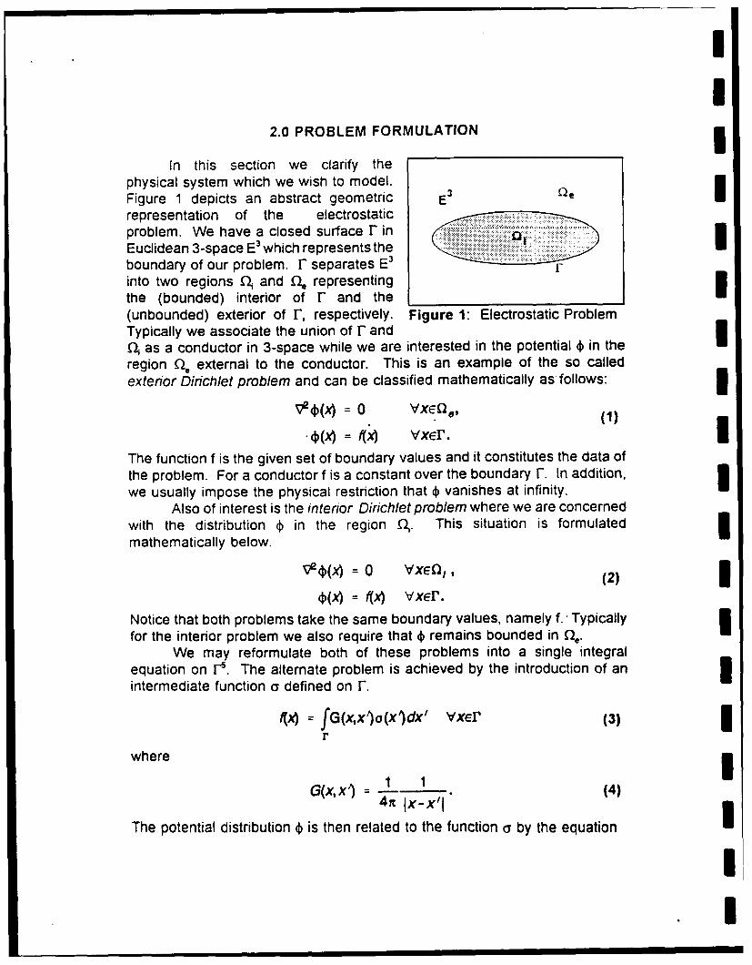
2.0 PROBLEM FORMULATION
In this section we clarify thephysical system which we wish to model.Figure 1 depicts an abstract geometric E3 Qe
representation of the electrostatic .problem. We have a closed surface I- inEuclidean 3-space E3 which represents theboundary of our problem. F separates E3
into two regions q. and fl representingthe (bounded) interior of r and the(unbounded) exterior of F, respectively. Figure 1: Electrostatic ProblemTypically we associate the union of r andQ- as a conductor in 3-space while we are interested in the potential 4) in theregion Q, external to the conductor. This is an example of the so calledexterior Dirichlet problem and can be classified mathematically as follows:
V (X) = 0 VXGQ, (1)
, = x) vxEr. IThe function f is the given set of boundary values and it constitutes the data ofthe problem. For a conductor f is a constant over the boundary F. In addition,we usually impose the physical restriction that 4 vanishes at infinity.
Also of interest is the interior Dirichlet problem where we are concernedwith the distribution 4) in the region (•. This situation is formulatedmathematically below.
VVxe(x) = 0 vxo,, (2)
4)(x) = f(x) vxer.
Notice that both problems take the same boundary values, namely f. -Typicallyfor the interior problem we also require that 4 remains bounded in 0,.
We may reformulate both of these problems into a single integralequation on r•. The alternate problem is achieved by the introduction of an 3intermediate function a defined on F.
4x) = fG(xx)o(x)dx' vxer (3)r
w h e re x
G(x,x') - 1 1 (4)
The potential distribution ) is then related to the function o5 by the equation
II3
4(x)= fG(x,xi)o(x)dx' VXeQ (5)r,
where 0 is the union of • and fl. Thus equation (5) is valid in all spaceexcept the boundary r. We recognize G(x,x') as the free space Green'sfunction for Poisson's equation and equation (5) as the potential due to asurface charge density a in free space. It is interesting to note that eventhough problems (1) and (2) are not related in any obvious manner, solution of(3) yields the correct a in both cases given the same boundary values f.
3.0 THE METHOD OF MOMENTS
We now approximate a in equation (3) using the method of moments.It will be convenient to rewrite (3) by defining the operator K. We have
Ka afG(x,x')a(x')cx1 = f feL~(I) (6)r
where we have chosen f in LP in orde~r to analyze convergence. We see thatK is a compact linear self-adjoint integral operator with kernel G(x,x'). Since ris compact, we may choose a countable set of functions {uj which are densein L,,("), that is they form a basis for the vector space Lj(r). These functionsare usually referred to as the set of expansion functions. Accordingly, anyelement of LP may be approximated arbitrarily well by . ý,inear combination of3 these functions. Thus,
a(x) = _afut(x) (7)I =n-1
for some set {aj} of coefficients. By substituting (7) into (6) and using thei linearity of K we have
ia,,Ku, = f. (8)I 11.1
Now we choose another set of functions {v,() in Lq (where 1/p + 1/q = 1) to beused as a set of weighting functions. By taking the inner product of (8) witheach of the v,'s we get a set of equations of the form
j, a,7(Ku,7, vm) = Yf, vm) m= 1, 2,3,... (9)
where ( -, -) denotes the usual inner product
I (u,v) = fu(x)iRx)dx. (10)Ir
I
II
Note that since f is given and {u,,} and {v,} are selected arbitrarily, the onlyunknowns are the coefficients {aJ}. To obtain an approximation for a we must Itruncate the indices n and m at a finite value. If we choose the same value forboth indices, say N, we are then left.with the following matrix-vector equation.
(Ku,, v,) .(KuN, v,)", v,
,(Kul, vN) .. (KUN, vN),aN) Y, v.),which can be written more compactly as
Ax = y. (12)
The matrix A is known in the literature as the moment matrix for (6), since wetake the moments of Ka with respect to the weights {v,}. Equation (12) maybe solved by standard matrix techniques to yield a solution for x, the vector ofcoefficients ( a1, ... , aN )T. We then have our approximation to a according to Iequation (7).
COMMENTS I(1) The method of moments generates solutions that converge in the mean, i.e.
in the Lp norm. The exact L. space where convergence occurs depends on 1the choice of expansion and weighting functions.
(2) When we chose {vmJ = {um,}, we have Galerkin's method which is known tobe equivalent to the Rayleigh-Ritz variational method 3. Thus, we see that Ithe method of moments is a generalization of the Rayleigh-Ritz procedure.For Galerkin's method we have convergence in the L2 norm (mean-squaredconvergence), where the approximate a lies in span {uJ}.
(3) By choosing {v.,} = {8(x-xm)} where 5 is the Dirac delta function and the x,,,sare some set of points on r, we have a point-matched solution. Suchsolutions are known to converge in the L, norm (pointwise convergence).
(4) For valid solutions we must make sure the set {Ku,} spans the range of K.Otherwise, we converge to solutions to the problem Ka = Pf where P is theprojection operator onto the space span{Ku}).
(5) K1 is unbounded and there exists f in LP such that (8) has no solution a inLP (such solution may however be interpreted distributionaFy). However, Kis a positive operator, indeed (Ka,a) is recognized as the electrostaticenergy in the system. Consequently, in the discrete approximation, 0 is notan eigenvalue of A (it is in the limit N-*.o, though).
4.0 CONJUGATE GRADIENT ALGORITHM
We now turn our attention to the task of solving the matrix-vectorequation (12). The traditional approach is to use some direct method such as
I
I.
LU decomposition or Gaussian elimination. With these techniques the amountof computation necessary to solve an N1h order system is known a priori. Forexample, it is known that inversion of (12) requires O(N 3) operations. Instead,we have chosen an iterative technique where the amount of computation is notknown in advance.
The conjugate gradient algorithms are a specialization of the moregeneral technique of conjugate directions methods. These techniques areexpressly developed to solve the problem8
min g(x) = '-x TAx - y Tx. (13)xei" 2
It is assumed that the matrix A is positive definite so that a solution does exist.Note that the solution to this problem, obtained by setting the gradient of g tozero, is given by x = A'y. Conjugate direction methods are based on the ideaof generating a complete set of linearly independent vectors {d,} which havethe property dnTAdm = 0 whenever m;n. This is known as A-orthogonality, orA-conjugacy.
Instead of solving (12) directly, in conjugate gradients we choose toiteratively minimize some functional, for example g in the above equation. Thevalue of x furnishing this minimum is the solution to (12). The method startswith an initial guess for x0, then it generates a sequence x, that minimizes thefunctional. The sequence {xi} will converge to the exact solution x in a finitenumber of iterations. Even if the matrix A is not invertible in the classical sense(0 is an eigenvalue of A), the conjugate gradient algorithm will converge to asolution in the least squares sense. The algorithm we have chosen was takenfrom Sarkar el. al.4 The functional which it minimizes is the (12) norm squaredof the residual ri = y-Ax, (i.e. minimize Ily-Ax 11 ).
n 5.0 IMPLEMENTATION
* To apply the method of moments it isnecessary that we select an appropriate setof expansion functions {un) and weighting
functions {vJ}. Since our aim is to minimizecomputation, we have selected a point-matching procedure. Thus, our weightingfunctions {vJ} are given by the set {(5(x-x)}where the xn's are the match points in r tobe determined. This technique yields theleast computing time, and the procedure isstraightforward. It also yields good resultsas long as one is careful in the selection ofthe match point locations 7'8 .
We choose a set of piecewise Figure 2: Triangulated Sphereconstant functions for {u,}. First, F" is
I
II
divided into triangular subdomains. denoted by the set {Tj} where n runs from1 to N. If r has curvature then we have an approximation to F- as well (forexample figure 2 depicts the triangulated approximation to a sphere). Now letthe un's be a sGt of piecewise constant functons on each T,.
U ;f x T = (14)u.(x 0 = ff x• T,,
It can be shown that such a set is dense in LP so a may be approximatedarbitrarily well9 . Thus, according to comment (4) we must be certain that Pf ={f(x,)) is in the span of {Ku.}. We shall see later that this criterion placesrestrictions on our triangulation of F. We have chosen the matching point set{x,} to be the centroids of each triangle T,. Since this is the center of mass forour constant expansion functions, it seems to be a reasonable approximation Ito f across the triangle face.
In order to form equation (11) we must determine the inner products(Ku1,5(X-Xn)). For our choice of expansion functions, this amounts to the Ievaluation of the following integral.
af fG(x~,Ix' )dx'= 1 dx'dy'dz' (15)
4M V/(X _X32 ÷(Y/ _y)2+(z _Z,)'
This can be done completely _
numerically, hybrid analytic andnumeric, or completelyanalytically°O. /
6.0 EXAMPLES
We have implemented theabove techniques in a computer ,.program written in Borland C++.The platform is an i486 PCoperating at 33 MHz and running I.u..,.CWindows 3.1 operating system. Figure 3: Conducting Sphere Axial IAll examples were run in single Potentialprecision arithmetic except wherenoted. We have taken arbitrary units.
CONDUCTING SPHERE IThe analytic potential distribution for a conduction sphere of radius 1 and held
I
at a potential 1 is known to bem ~1 if IxI< 1,
I = if 1xI x : 1. (16)
1Ix
Figure 3 shows a comparison of this analytic formula with the numerical resultsachieved for a triangulated sphere of 432 triangles (shown in figure 2). Thesolution converges to a norm squared residual error < 10-9 in 75 iterations
I taking about 7 minutes real time (double precision required 42 iterations within5 minutes).A single number which is indicative of solution quality is the capacitance. This
I value may be calculated by recognizing a as surface charge density. Wenumerically calculated the capacitance to be 110.2 pF for the above situationin MKS units, the true value is 111.3 pF.
EINZEL LENS
3 An einzel lens was modeled'as twocylindrical pipes of radius 5 andlength 10, separated axially by adistance of 3. Both pipes werecapped with plates having an innerradius of 1/2. A conducting platewith outer radius 5 and inner radius ',
1/2 was centered between the twopipes at position z=0. The centerplate was driven to a potential of1 while the two outer pipes were - numen.c arprx. araiyl,'cgrounded. EI-Kareh provides anapproximate analytic axial potential Figure 4: Einzel Lens Axial Potential
This approximation assumes three infinite plates of inner radius 1/2 withuniform fields at z = ±oo. The discretization was made with 464 triangles. Thissystem took 261 iterations to converge to the usual error criterion (about 18minutes of real time). What is happening here is that our boundary function fof equation (8) is almost outside the range of {Kun}. Fortunately, our iterativetechnique is indicating this situation by slower convergence! In order to avoidsuch situations it is necessary to reevaluate the triangulation of the system toinsure that {Kun) spans the space of boundary functions. Even though ourpatch model was borderline ill-conditioned, the stability of the conjugate
I
II
gradient method still yielded reasonable results (see figure 4).
7.0 CONCLUSION
The method outlined in this paper exhibits enough computational Iefficiency to allow practical implementation on a PC. It yields accurate resultsin a reasonable amount of real computing time. Moreover, the conjugategradient algorithm furnishes suitable error criterion to judge the quality of thesolution. However, tne method does require more work to implement than, say,the rather straightforward technique of finite differencing.
REFERENCES
1. S. K. Guharay, C. K. Allen, and M. Reiser, Conf. High-Bright. Beams, CollegePark, AlP Conf. Proc. 253 (1992), pp. 67-76.
2. S. K. Guharay, C. K. Allen, M. Reiser, K. Saadatmand, and C. R. Chang, AlP Conf.Proc. on Product. and Neut. Negative Ions (1993) (to appear).
3. R. F. Harrington, Field Computation by Moment Methods (Krieger, Malabar, FL,1968).
4. T. K. Sarkar and E. Arvas, IEEE Trans. Antennas Propagat., vol. AP-33, no. 10, pp.1058-1066, Oct. 1985.
5. I. Stakgold, Green's Functions and Boundary Value Problems (Wiley, NY), pp. 508-517.
6. D. G. Luenberger, Linear and Nonlinear Programming 2nd Ed. (Addison-Wesley,Reading, MA, 1984), pp. 238-257.
7. T. K. Sarkar, A. R. Djordjevic, and E. Arvas, IEEE Trans. Antennas Propagat., vol.AP-33, no. 9, pp. 988-996, Sept. 1985.
8. A. R. Djordjevic and T. K. Sarkar, IEEE Trans. Antennas and Propagat., vol. AP-35,
no. 3, pp. 353-355, March 1987.
9. H. L. Royden, Real Analysis 3rd Ed. (Macmillan, NY, 1988), p.282.
10. S. M. Rao, A W. Glisson, and D. R. Wilton, IEEE Trans. Antennas and Propagat. Ivol. AP-27, no. 5, Sept. 1979, pp. 604-607.
11. A- B. EI-Kareh and J. C. J. EI-Kareh, Electron Beams, Lenses, and Optics Vol. 1 I(Academic Press, NY, 1970), p. 187. I
I
It.
Proceedings of the 1993 Particle Accelerator Conf., May 1993, Washington, DC
I An ESQ Lens System for Low Energy Beam Transport Experimentson the SSC Test Stand
S. K. Guharay, C. K. Allen. M. ReiserLaboratorv for Plasma Research. University of Maryland. College Park. MD 20742. USA
and K. SaadatmandSSC Laboratory, Dallas. TX 75712. USA
3 4bstract
A low-energy beam transport system is designedwith the aim of transporting a 30 mA. 35 kV H-beam from a volume source and focusing it into anRFQ. The characteristics of the beam from the sourceare determined analyzing the emittance data. The .
behavior of the beam through the LEBT is stud- jied using simulation codes. The system parametersare optimized so that the LEBT has a very modestcontribution to the emittance growth (here a factorof about 1.5) and the emittance budget of the linacsection is maintained.
I. INTRODUCTION ,. 0,
One of the vital considerations in modern high- Figure i: Contour emittance plot.energy accelerators is related to the design of an effi-cient low-energy beam transport (LEBT) section sothat an intense, high-brightness beam (here we con- from the SSC volume source with the aim of design-
sider an H- beam) can be transported over certain ing a LEBT system to deliver a 30 mA. 35 kV beamdistance and finally focused into the commonly used matched with the RFQ input.RFQ accelerator in the linac section. The emittancegrowth in the LEBT is the key issue in developing II. BEAM CIARACTERISTICS.a good scheme at the low-energy end of the acceler-ator chain. "thus. in order to achieve a good beam The H- beam from the SSCL volume source isquality and match it to the acceptance of an RFQ a measured at 10.13 cm downstream after the electrons
systematic study of beam dynamics in the preceed- (ratio of initial electron to ion current - 40) are de-ing sections including the extraction optics of the flected away from the extracted beam current by a 10ion source is warranted. We have experienced thatemittance measurements of the beam from an ion cm long magnetic trap. Figure I shows the contour
source and an analysis of the data to characterize plots in the x - x' space from emittance diagnos-sothe beam at the dtti to arecterz tics; the flattening of the distribution in the upperth pblems i the extraction electrode are two impor- half is possibly caused by the space-charge force dueitant problems in the context of designing an effcient teeetosdfetduwr.Teba aLEBT. Earlier we reported [1,21 on the beam char- to the electrons deflected upward. The beam pa-
icteizaionand eamdvnmic thrugf a EBTrameters at z = 10.13 cm are: beam size D = 2.38a•cterization and beam dynamics throug~h a LEBT
for H- beams from a P-enning-Dudnikov type [3 cm. full divergence A8 = 260 mrad. ri = 0.1537rand magnetron type sources. In recent years sig- mm-mrad. These data are used in an envelope sim-nificant progress has been made in the performance the extraction electrode; space-charge effects due to
of volume sources (4,51; normalized beam brightness the etrction elextraction e-hare included.approaches about 1011 A/(m-rad) 2 for H- beams. red areThis article highlights on the study of H- Figr 2(a) shows the assumed space-charge cofrec-
Thisartclehighighs o thestuy o H-beams tion factor. f, due to the electrons. Note that st is
IRFQ. It has been shown eariier that a short Iabout 5
cm long) single einzel lens module between an ESQLEBT and the RFQ will be a good choice in satis-fying the aforementioned stringent conditions of theRFQ [21. The ESQ LEBT transforms the highly di-verging beam from the ion source into a moderateivconverging one without any significant emittance di-lution. and the einzei lens provides the final strong
"", focusing. This analysis showed that the parametersI (C.. of the output beam from the ESQ LEBT should fol-
___ low: beam radius - 3 to 5 mm. the correspondingslope of the beam envelope - -30 to -50 mrad.
III. BEAM TRANSPORT THROUGH THE ESQ I34 LEBT
The design principles of the ESQ LEBT followthe scheme as discussed earlier (1.21. The presentconfiguration of the magnetic trap in the extractionregion of the SSCL volume source restricts the ESQ
.1• •LEBT's distance to the extraction aperture to about(ZcM) 10 cm. This causes the beam to blow up significantly
(Fig.1). After a detailed analysis with such a beamFigure '2: (a) Space-charge correction factor f; (b) it is recognized that the goal to deliver a matchedbeam envelope. z = 10.13 cm corresponds to the beam to the RFQ for the full beam current (30 mA)location of ermittance measurements. is a very difficult task. Our analysis suggests that
a shorter magnetic trap (about 5 cm long) will benegative here and the beam perveance is to be mul- a better choice. Figure 3 shows the beam envelopetiplied by the factor ( I - f). The beam envelope in through the ESQ LEBT when a hard-edge focusingFig. 2(b) is evaluated bv integrating the K-V en- function for the external field is assumed. An initialv%,lope equations using a fourth-order Runge-Kutta drift space of 5 cm long is considered, and a pro-method. This analysis suggests that the beam at the file of the space-charge correction factor due to the,,xtraction electrode emerges nearly parallel, and the electrons (Fig. 3, bottom) is assumed. The beam pa-beram size is close to the aperture radius (= 4 mm). rameters at the extraction aperture are taken from
the analysis of Fig. 2. The maximum aperture ra-8. Desired Output Beam Parameters from the ESQ dius of the quadrupoles is 22 mm: it was taken asLEBT 12 mm when the LEBT was closer (i.5 cm) to the *
The purpose of the LEBT section is to isolate extractor (fl. Ithe RFQ from the ion source for a clean operation The distribution of the beam particles throughand also to deliver a matched beam to the RFQ. The the ESQ LEBT is estimated using a modified PAR-SSC RFQ acceptance for a 30 mA, 35 kV H- beara MILA code 16]. Figure 4 shows the particle dis-is given by the Twiss parameters: a = 1.26, /3 = tribution in phase space for I = 30 mA. The esti-1.86 cm/rad. ri, = 0.2 7r mm-mrad. As the normal- mated output beam parameters are: X = 3.5 mm.ized rms emittance of the H- beam from the source V, = 3.5 mm..X' = -51.7 rnrad. Y' = -50.8 mrad. Iis about 0.1537 i" mm-mrad (Fig. 1). the LEBT is / = v5. The emittance growth is primarily dueto be designed under a very tight emittance bud- to chromatic aberrations.get. The matching condition dictates that the beam Iparameters at the tip of the RFQ vane should be: IV. CONCLUSIONSbeam radius = 1.3 mm and the corresponding slope Emittance measurements of a 30 mA. 35 kV H-of the beam envelope = -89 mrad; this is located at semtutd.e ms vurmensUof a ,ee stud-about 3 cm downstream from the front wail of the ied. The sSCl volume sugge hat the H-ied. The simulation resuits suggest that the H- I
-.
beam envelope has a waist at the extraction aper-ture. With this definition of the input beam anda given set of characteristic parameters of the RFQacceptance. we have designed a LEBT system. The
('I C( Iparticular design of the LEBT consisting of six ESQlenses and a short einzel lens can transport the full
___ beam current and match it to the RFQ.Beam transport experiments with a prototype
ESQ LEBT will be conducted to validate the simu-lation predictions. Further, the 3-D LAPLACE sim-ulation scheme is being improved using a method of7 7moments where any arbitrary boundary can be rep-resented numerically and the practical problems willbe simulated more realistically [7].
This work was supported by ONR/SDIO and, DOE.
DOE.IV. REFERENCES
[1] S. K. Guharay, et. al.. Proe.1991 Particle Accel--,,- 3 . erator Conf., p. 1961.
[21 S. K. Guharay, et al.. BNL Conf. on Production
Figure 3: K-V envelope solution. and Neutralization of Negative Ions and Beams. Nov.1992 (to be published in AIP Proc.).[3] P. G. O'Shea, et al.. Nucl. [nstrum. 6- Meth. in
! __0 Phys. Res. B40/41. 946 (1989).[4) K. N. Leung, BNL Conf. on Production and Neu-tralization of Negative Ions and Beams, Nov. 1992
(to be published in AIP Proc.j.. [5] K. Saadatmand. these proceedings.
[6] C. R. Chang, Ph. D. Thesis. Univ. Maryland.% 1989.
0 [71 C. K. Allen. et al.. these proceedings.
X~ (mmI
.00
-989
IFigure 4: Particle distribution at the output of theESQ LEBT.I
A COMPACT ESQ SYSTEM FOR TRANSPORT AND FOCUSING OF H- BEAM
FROM ION SOURCE TO RFQ"
S.K. Guharay, C.K. Allen, M. Reiser
University oi Maryland. College Park, MD 20742 USA
andK. Saadatmand and C.R. Chang
Superconducting Super Collider Laboratory, Dallas. TX 75237 USA
Abstract
* A compact. 6-lens electrostatic quadrupole (ESQ)LEBT system has been constructed at the Universityof Maryland to transport a 30 mA. 35 kV H- beamover a distance of about 30 cm. A short einzel lens,.section is included at the end of the ESQ LEBT toestablish a good matching of the beam to the radio- Iifrequency quadrupole (RFQ) accelerator. and to meetthe emittance requirements of the linac in the Super- ".-conducting Super Collider. Computer code predic-tions on the beam dynamics through the LEBT with Figure 1: The LEBT system.
I experimentally measured input beam data are dis-"cussed. section plays a critical role in the performance of the
Introduction linac.This article addresses some important problems in
An efficient ion source-cum-low energy beam trans- designing an efficient LEBT system. Here. an ESQ
port (LEBT) section is highly desired to deliver a lens system is primarily considered: two other vari-
good-quality beam to the low-energy booster (LEB) ants of the LEBT system, einzel lenses and a helical
in the collider ring chain of SSCL. The intrinsic emit- quadrupole lens. are also being investigated in the
tance of the V1 beam from an ion source. volume- present context at SSCL [3]. The analyses are based
, ionization or magnetron type. is typically about 0.12 on computer code simulations. where the input beam
7I mm-mrad ( rms normalized value); the LEB requires parameters are mostly taken from experimental mea-
that the transverse beam ernittance at the output of surements.
the linac section be < 0.3r mm-mrad (1]. The compo- Beam Dynamics, Design of LEBT andnents of the iinac between the ion source and the LEB Discussionsare: LEBT. radio-frequency quadrupole (RFQ) ac-celerator. drift-tube linac (DTL) and coupled-cavity In our previous paper [4]. we described a 6-lenslinac CCL). Computer code analyses of the beam dy- ESQ LEBT system developed at the University ofnanics through the DTL and the CCL suggest that Maryland. The predicted performance of the ESQthe emittance growth in these two sections is not sig- LEBT are now examined in the light of beam param-,ificant. being in the range of 10-15% [2]. The per- eters relevant to the SSCL program. Two types of H-formance of the RFQ, e.g., beam transmission and sources are considered in the SSCL injector develop-emittance growth. depends primarily on the Twiss ment - a volume source and a magnetron source.parameters of the beam at its input: the transverse In the context of the volume source, we have usedrms normalized emittance of the input beam is de- the beam parameters corresponding to a Brookhavensired to be < 0.21r mm-mrad. Hence the LEBT's National Laboratory (BNL)-tvpe source (51. Acontribution to the emittance budget must be main- 30 mA. 35 kV H- beam is extracted through a I cm 2
tained within a factor of 1.6 of the input beam emit- circular aperture. A parallel beam is assumed totance. This suggests that the ion source-cum-LEBT emerge from the extraction aperture. The beam en-
' velope through a compact 6-lens ESQ LEBT section""Supported by ONR/SDIO and DoE Contract #D,-AC35- (Fig.l), which has been constructed in-house at
I
ZICMIe -.- -i
0--:200
-... - -I--'
- _- |__
Figure 2: Linear beam optics result for a parallel in- nput beam. Top: Amplitude (X. Y) of the beam enve-lope through the ESQ LEBT along x (solid line) andy (dotted line); bottom: focusing function. x. z is the -
direction of propagation of the beam. __
Rt mm.
Maryland. is computed by integrating the K-V en- ligure 3: SNOW-2D results for the einzei lens mod-velope equations using a fourth-order Runge-Kutta tile. Fop: Beam trajectory through the einzel lensmethod. Figure 2 shows the beam envelopes, when a module. The center electrode is at -36 kV and thelinear external focusing force represented by a hard- two end electrodes are grounded. Middle: Phase- U,dge focusing function. x(-). is assumed. .. s men- space distribution of the input heam. Bottom: Phase-tioned in the previous article (41, the SSCL RFQ re- .pace distribution of the output twain.quires a circular beam of about 1.3 mm in radius and Ia beam convergence of about -90 mrad at rmn,. Tomatch these conditions without sacrificing the emit- are predicted. A plausible •stimate ol the heam pa-tance growth. an additional unit. a single-piece einzei rameters at the tip of the extraction cone is: beat Ilens module, is included at the end of the ESQ LEBT radius = 1.1. mm. and divergence at rma, = 72 mrad.section (Fig.i). The particle distribution at the out- The lens aperture in the ESQ LEBT in Fig.i is notput of the ESQ LEBT is computed using a modified large enough to accommodate the highly divergingPARMILA code (61, and it does not show any signif- It- beam from the magnetron source. A preliminaryicant emittance growth. •< .5%. Results in a similar design study reveals that the aperture of the IKSQsituation have been shown earlier (4]: this point is not lenses. second through fifth in Fig. I. is to he increasedelaborated further. The einzel lens turns the moder- by a factor of 2: this demands a higher voltage on theately convergent (-,- -20 mrad) beam from the ESQ quadrupoles. The beam dynamics through the ESQLEBT into a strongly convergent (- - 110 nirad) T.EBT is followed using the modified P.\RMILA code.
beam with a negligible emittance dilution. < 5%. The Figure 4 shows the output beam distribution t bottoi tbehavior of the beam through the einzel lens section. figure), when a K-V type input beami (top figure) ispredicted by the SNOW-2D code. is shown in Fig.3. assumed. The ground plate in front of the second lens
The aforementioned analyses have been carried out in Fig.l has been used as a beati scraper to rejectusing the parameters of a .30 mA. 35 kV It- beam ex- about 15% of the beam particles, which contributetracted from the SSCL magnetron source. The char- significantly to the emittance growth. The outputiacteristics of the beam are measured at a distance of beam in Fig.4 still suffers from some distortions. giv-11.75 cm downstream from the tip of the extraction ing rise to an emittance growth by a factor of aboutcone. Using these results as initial beam conditions. 1.5. Further optimization of the ESQ LEDT is war-
the beam parameters at the tip of the extraction cone ranted to improve the present situation. Nevertheless.
I
,-." 2.- ! -.--! !
aZ (ago
S * *LOO,
Figure 4: Modified PARMILA results on particle dis- ,.tribution for H- beam from the SSCL magnetron . -...source. Top: input to the ESQ LEBT. Bottom: out- "put from the ESQ LEBT.
.100,100,an output beam current of Z 25 mA. as required for , -.
the SSC RFQ, is achievable from the ESQ LEBT. Inregard to matching the beam to the RFQ, an einzellens module is included at the end of the ESQ LEBT. -
Figure .5 shows preliminary results of beam transport -__ -_.through the einzel lens module. The smooth nature4)f the input beam is an artifact of modeling it froman estimate of the effective values of beam parame- -Rmmu
ters in Fig. 4. The einzel lens does not contribute Figure 5: S4OW-2D results for th~e einzel lens mod-to the emit.ance growth: the beam parameters at the tile. Top: Beam trajectory. The center electrotic isfront end of the third electrode (at ground potential)Uriatch closely to the acceptance ellipse of the SSCL at -36 (fe Middle: Phase-space distribution of the
RFQ. input beam (Effective values from Fig..1 are used to
The above analyses for the LEBT have been done in i model it.) l3ottom: Phase-space distribution of the
i two separate stages- first the ESQ lenses with modi- output beam.
tied P.\ RMILA and then, the einzel lens with SNOW-"2D. The simulation predictions will hold well. if the being planned on the SSCL test stand to study thematching between the two codes is complimentarv. beam characteristics through the I'SQ i.ETr ,ysternAn effort is being made to include the option of an developed at Maryland. and test the reliability of sitn-",,inzei lens in the modified PARMILA. when a more uilation predictions.reliable design tool will be available.
ReferencesConclusions
[he problem of low-energy beam transport and its [1] L.V. Funk. these Proceedings. paper 4%1l0-2.[12) D. lHaparia. et ;il.. these Proceedings. p.plr
matching to an RFQ has been studied in reference to #%1O4-66.: ibid. paper #MO-1i66.two special cases of the input iV- beam: (i) a parallel [31 K. Saadatmand. et al.. these Proceedings. paperbeam. and (ii) a highly divergent beam. The compui- #M04-20.rational results suggest that the key point in design- [41 S.K. Guharav. et al.. Proc. 9th Internationaling an efficient H- injector (ion source-cum-LEBT) Conf. on ifikh-Power Particle Beams. Washington.relates to achieving a well-conditioned beam. e.g., un- D.C.. \lay 25-29. 1992. paper -PB136 (to he pill-aberrated and near-parallel, from the ion source. An lished).emphasis is laid here to develope an LEBT appara- {51 J.G. Alessi. private communication.tus with compactness, mechanical stability and flex- (61 C.R. Chang. et al.. SPIE Proc. on Intense Mi-ibility for easy modifications. A combination of a crowave and Particle Beams. vol.1226. p.483 (1990).6-lens ESQ module and one short einzel lens module.as adapted in the present LEBT design, appears tobe a good choice in this respect. An experiment is
I
I Paper submitted to Nuclear Instruments & Methods in Physics Research.
Study of Beam Dynamics for an Intense, High-BrightnesWH- Beam to Design an Efficient
Low-Energy Beam Transport Using ESQ LensesIS. K. Guharay, C. K. Allen, M. Reiser
I Laboratory for Plasma Research, University of Maryland, College Park, MD 20742, USA
IAbstract
3 With an aim of transporting an initially diverging high-perveance (generalized beam per-
electrostatic quadrupole (HESQ) lens. Until now, the utility of RFQ lenses has been least
explored. In the category of electrostatic lenses, einzel lenses are commonly used. The con-
ventional einzel lenses have a drawback in that plasmas may build up in the field-free region,
rendering the system susceptable to beam-plasma instabilities. Anderson's "ring" lens ver-
sion appears to be free from this problem [8]. The einzel lenses require power supplies close
to the beam voltage, typically - 30 kV for a 35 kV beam; the ESQ lenses have an edge over
the einzel lenses in this respect. Several practical factors, e.g., tuning with low-voltage power
supplies (typically < 10 kV), elimination of any field-free region, and ease of computer mod-
eling, make the ESQ system a very attractive choice as a LEBT. Reiser [13] reported briefly
a comparative study of the aforementioned LEBT schemes. It is understood that in spite of
a good deal of research involving LEBT systems, a systematic study of beam dynamics and
optimization of LEBT parameters has not been made in the context of transporting intense,
3I
Ihigh-brightness H- beams. In order to obtain insight into the problem and advance the
present state-of-the art of LEBT systems, detailed simulation studies should be first made,
and the simulation predictions compared with experimental results. In a recent article Bru
enumerated a beam transport program in which all the forces are considered linear f14J. The
present article addresses in detail for the first time the beam dynamics issues relevant to
designing an ESQ LEBT for intense, high-brightness H- beams incorporating the various
nonlinear effects due to aberrations, fringe-fields, etc.; a special emphasis is given here to Iunderstanding emittance growth and methods to control it. Typical beam parameters of a
Penning-Dudnikov type ion source are considered in which the generalized beam perveance
K = 0.003 and normalized beam brightness B, -- 101 A/(m-rad)2 ). Here, K is defined as
the ratio of 2Ib/Io#3.y, where Ib is the beam current, I0 is the characteristic current (3.1 x 10⁷
A for H- beam), #3 = v/c, y = (1 _ 32)-1/2.
Some key physics issues on emittance growth in an ESQ LEBT and its control are in-
vestigated in detail. The simulation scheme is developed in steps. A linear beam optics Icode is written to integrate the well-known K-V envelope equations. The lens parameters
are approximated from this analysis. A 3D Laplace solver maps the equipotentials of the
lens system, and the fringe fields are evaluated. Several articles have dealt with fringe fields I[15-20]. Following the method of Matsuda and Wollnik [19], the effect of the fringe fields is
included here in a particle simulation code, which essentially is a modified version of the well-
known PARMILA code [21]. The evolution of emittance through the ESQ LEBT channel is
determined from the modified PARMILA code. This simulation scheme is iterated until a Isatisfactory solution is obtained. The analysis is made here in the context of transporting
an initially round (radius = 1 mm), diverging (slope = 20 mrad at the full beam radius) 30
mA, 35 kV H- beam over a length of about 30 cm and transforming it into a round (radius
-1 mm), converging (slope - -40 mrad) beam. The control parameters of an ESQ lens
can be simulated reasonably well, and this permits to delineate an in-depth investigation of
the various sources of emittance dilution. This study thus establishes a strong foundation
for designing an efficient LEBT system. Some comments are made on the development of I
4I
I
the IEBT system and its experimental tests; details are beyond the scope of this paper and
these issues will be reported elsewhere.
Section 2 pertains to the beam dynamics. Some characteristic features of the LEBT
system are given in Section 3. Section 4 includes conclusions.
2. Beam Dynamics through the ESQ LEBT
A. Linear beam optics calculations
The study of beam dynamics in an ESQ LEBT system is developed from a rather simple,
idealistic model in order to set up the lens parameters grossly. Afterwards, the simulation is
done including various practical features , e.g., real geometry of the electrodes, fringe fields,
aberrations, etc. First, a beam optics code, which includes a linear external focusing force,
here a hard-edge type, in the K-V envelope equations is used; this integrates the following
coupled equations by fourth-order Runge-Kutta method and gives the behavior of the beam
envelope.i2K
2X" + K_____ - --fz=0,
2K 2 =0.I Y" (z)Y -y_X+Y Y3
E and f are the x and y components of the unnormalized beam emittance, respectively.
The focusing function due to the externally applied force is r = V4/(V 6R2), where V. is the
applied voltage on the quadrupole, Vb is the beam extraction voltage, and Rq is the aperture
radius of the aperture radius of the quadrupole. The derivatives are taken with respect
to z, which follows the direction of propagation of the beam. The amplitude of the beam
envelope, X(z) and Y(z), is determined using certain values of the input beam parameters
and an assumed configuration of the lens geometry. In the case of any gas accumulation
in the channel, which may occur at the interface between an ion source and a LEBT, the
above equations are solved with the beam perveance term K multiplied by (1 - - 2f); f is
the charge neutralization factor and - = (1 - 1/2.
In order to validate the results predicted by the linear beam optics code, the various
nonlinear contributions, namely due to aberrations, fringe fields and image effects, are to be
5
I
minimized. The following constraints control the nonlinear effects (221. I(i) If the maximum beam excursion is not allowed to exceed 10% of the length of a
quadrupole 1, spherical aberrations may be kept at low level.
(ii) To reduce chromatic aberrations, the change in the beam energy due to the quadrupole
focusing field should be less than about 5% of the total beam energy qV6.
(iii) The image field may be neglected if the maximum excursion of the beam envelope
remains within 75% of the quadrupole aperture radius R,.
The following empirical relationship is satisfied to avoid any voltage breakdown [271
d (cm) > 1.4 x 10⁻³ V3/ 2 (WV),
where d is the interelectrode spacing and V is the voltage difference.
Due to limited accessibility in the neighborhood of the beam extraction region, it is
difficult to obtain a reliable knowledge of beam parameters at the extraction point; this
introduces some ambiguity in the initial values of the beam parameters which are given as
input to the code. Usually measurements are made at a distance of about 10 cm downstream
from the extraction slit and the data are interpolated using some simulation model to predict
beam parameters at the extraction point. Table 1 lists the estimated values of the H- beam Iparameters corresponding to the Penning-Dudnikov source used in the BEAR experiment,
when the nominal emittance data [24] measured at a distance of 10.6 cm downstream from
the extraction aperture have been used.
The desired solution is obtained after several iterations, when the lens parameters (e.g.,
aperture and dimensions of the individual lenses, spacing between the lenses, and number Iof lens elements) are adjusted at each step. As mentioned earlier, the beam envelope is
constrained at each stage through the LEBT system so that distortions due to aberrations
and image effects are minimized. The LEBT system has been thus configured using a set
of six ESQ lenses. The geometrical parameters of the lenses are given in Table 2. Here I is
6I
IIthe length of an electrode and L is the separation between adjacent lenses. Note that the
geometrical parameters conform to a symmetric triplet configuration.
Figure 1 shows the K-V envelope solution (top figure), when the input beam parameters
correspond to Table 1 and a hard-edge type focusing function (bottom figure), K(z), is
assumed. The voltages on the three sets of similar lenses (1 and 6, 2 and 5. and 3 and 4)
are, respectively, 7.825, 3.875, and 3.820 kV. The envelope parameters of the output beam
(designated by subscripts f) at two locations are given in Table 3 to elucidate the nature of
focusing. z = 287 mmn corresponds to the end of the last lens in the LEBT. These results
suggest that the ESQ LEBT system can deliver a converging, round beam to the next stage,
typically an RFQ in the linear accelerator section, and the beam will be well matched if the
RFQ entrance is very closely (< 1 cm) coupled to the last lens of the LEBT.
An intriguing feature in the present LEBT is that the combination of the four lenses
(number 1, 2, 5, and 6) is used to transform the diverging input beam into a converging one,
while the other two lenses (number 3 and 4) act as a FODO transport section providing an
adequate length of the LEBT. The FODO section may be cascaded to obtain any desired
length of the LEBT.
* B. 3D field mapping and evaluation of fringe fields
The exact geometry of the lens system is used, and the equipotentials are mapped solving
the 3D Laplace equation. Cylindrical electrodes with some shaping of the end faces following
Laslett [25] and Dayton et al. [26J are used, when the field is expected to be quadrupolar
within about 90% of the lens aperture. In order to minimize interference between two
adjacent lenses [27], a grounded plate is inserted between the lenses. Figure 2 shows the
equipotentials of the ESQ lens system. Following the notations of Matsuda and Wollnik
[19], the potential distribution due to a quadrupole lens follows a symmetric behavior as
(XZ) = , Z),
O(z,y,z) = -O(x,-Y'Z),
(Z,) = O(X,,-),
if the four electrodes in a lens are biased at alternately positive and negative potentials. The
7
Ipotential distribution 0 can be expressed as
¢(X, Y,Z) = k(Z XI _y2) _2ý4 (x-y4) +.,I
2 24
up to the fourth order, while the electrostatic field components are governed by
up to the third order. The first term in the above expressions represent the field components
of a pure quadrupolar field; the fringe field, which has a nonlinear behavior, contributes due
to the second derivative term in k for E- and E. and is governed by k' for E,. The function Ik(z) is determined from the equipotentials. This result in conjunction with the values of the
beam amplitude at various z-locations from Fig. 1 is used to evaluate a comparative estimate
of the main field and the fringe field which the beam envelope is expected to encounter in
our particular design. Figure 2(a), (b), and (c) show the field components, respectively, in
x, y, and z-directions; Fig. 3 shows the effective magnitude of the field components. It is
evident that the contribution of the correction terms due to the fringe field is very localized
over a small region towards the edges of each lens in the ESQ LEBT, and the main field Isignificantly dominates. This suggests that geometrical aberrations may not be serious in
the present ESQ system.
C. Beam dynamics calculations and analysis of the sources of emittance growth
The results from the above two steps of analysis are used in a particle simulation code,
PARMILA, to study the beam dynamics in further details. This code essentially pushes
particles using a chain of transfer matrices, where the matrix elements are characterised by
the factors governing the motion of the beam, e.g., space charge, drift space, lens elements, Ietc. This code adapts the following key points.
(a) The space-charge force is calculated assuming the beam as an ensemble of typically
5000 ring-like macroparticles. The macroparticles follow certain distributions in both Iconfiguration and phase spaces, e.g., K-V, waterbag, semi-Gaussian, Gaussian, etc.
8 I
I(b) The electrostatic field due to the lens is decomposed into two parts: a main field of
hard-edge type within the lens region, and fringe fields outside this ideal boundary.
In order to get a realistic evaluation of the hard-edge boundary which can effectively
represent the quadrupolar field component of a lens, an equivalent length is defined as
l I = 1- IK(z)dz
where tc0 is the peak value of ic in the flat-top region as shown iii Fig. 2, z, and z,
correspond to the zero-crossing locations of rc(z) on the immediate two oppot.te ends
of a lens. A set of integrals involving k(z), as prescribed by Matsuda and Wollnik [191,
is used to model the force due to the fringe field. This force is applied at the ideal
hard-edge boundary, and the shifts and bends of the particle motion due to fringe fields
are incorporated in the PARMILA code (22].
(c) The trajectory of the macroparticles is followed systematically with due considerations
of field distributions over a cross-section of the beam. The energy conservation law is
followed to tackle this problem
12 1lmvo- + eVo = -mv(r) 2 + eV(r).
where vo and v(r) denote, respectively, the velocity of particles on the axis (this is
equal to (2eVb/m)1/ 2 ) and at an arbitrary location r, and Vo and V(r) correspond to
the electrostatic potential due to Lhe lens at the respective locations.
Figure 4 shows the behavior of the particle distribution at the output of the ESQ LEBT
when a K-V type distribution of the input beam particles is assumed. The distortions in the
output beam are due to nonlinear effects, and this leads to some emittance growth. In this
particular example, the emittance growth is a factor of about 1.6. The ellipses composed from
the Twiss parameters for the output beam show a very similar nature in the two orthogonal
planes; these ellipses are drawn using the effective emittance f = 4i due to Lapostolle 1291.
The corresponding characteristic beam parameters are: Xm&X = 1.6 mm, Y.. = 1.3 mm,
(Xmz)' = -41.7 mrad, and (Y.)' = -39.2 mrad; a better matching of the parameters
9
Iin the two orthogonal planes may be fortuitous. Various other types of distributions, e.g.,
waterbag, semi-Gaussian, Gaussian, have been also considered. The particle distribution of
the output beam in ;ts configuration space is shown in Fig. 5 for the various distributions. A m
small group of particles (<ý 5%) is detached from the dense core group in the case of Gausian
distributions; these particles are essentially lost from the system as their location corresponds Ito the boundary of the electrodes. The rapid blow-up of the beam for a non-KV distribution
may be an artifact of excess energy in tail particles of the distribution function. For the
sake of comparison of the beam behavior in the two extreme cases, the output beams are
shown in Fig. 6 for K-V and Gaussian (with the tail cut off at 4a) distributions of the input
beam. The phase-space area occupied by the core group of particles seems to be similar in
the two cases. The emittance of the output beam will practically follow the dynamics of a
K-V type input beam if distribution is tailored to a low-temperature beam. As a K-V type m
distribution is commonly used in the literature for basic analysis of beam dynamics and also.
it seems to represent well the beam distribution particularly in the case of a space-charge
dominated, high-brightness beam i281, we have extended our analysis assuming a K-V type
distribution of the input beam.
The evolution of emittance growth, as the beam propagates through the ESQ LEBT, is
shown in Fig. 7. It is noted that the emittance is primarily enhanced at the second lens in
the x-plane and at the fifth lens in the y-plane. This result conforms to the previous findings Ifrom the linear beam optics code when large beam excursions (Fig. 1) have been noted at
the aforementioned two lens elements; nonlinear effects act strongly when the amplitilde of
the beam envelope is large. In our simulation studies it is possible to diagnose the principal
contributors to emittance growth and reject some of the unwanted group of particles by
using appropriately shaped ground plates between the lenses as beam scrapers, and thus
the emittance growth may be controlled. Figure 8 shows an emittance growth by a factor
of about 1.3 only when a beam scraper is introduced between the third and fourth lenses;
about 15% of the beam particles is rejected here. This seems to be an easy way to control
emittance of the output beam.
II
In an effort to further understand the effect of nonlinear forces, the architecture of the
simulation code is made appropriately to evaluate the contribution of various factors piece-
Swise. i.e., term by term. First, the transverse energy of all the beam particles is numerically
maintained at a constant value through the entire LEBT. Figure 9 shows the output beam
distribution. It is evident that the output beam is free from any major distortions. The
3 emittance growth is estimated to be reduced by more than 90%. This suggests that the
chromatic aberration is the principal contributor to emittance growth in the present case.
Turning the fringe-field terms off in the simulation, it is noted that the emittance growth is
reduced very insignificantly. This indicates that geometrical aberrations do not play a major
*I role here.
The sensitivity of output beam parameters with variation of beam voltage, beam cur-
I rent, injection error has been studied. Using the linear beam optics code it is noted that
the beam parameters do not change noticeably for a ± 1% change of quad voltage (from the
ideal setpoint) on all the lenses simultaneously. Similar insensitivity is noted for variation
of beam current (ideal = 30 mA) within a few milliamperes. The effect of an injection error
is studied using PARMILA. With the variation of the amount of off-centering of the input
beam, the qualitative nature of the phase-space distribution of the output beam remains
almost invariant, while the beam centroid shifts coherently. A translational off-centering by
I 1 mil (= 0.0254 mm) at the input causes an off-centering of the beam by about 3 mil at the
output of the LEBT; this also introduces an angular error of the beam centroid by about
1.5 mrad. An on-centered input beam with an error in the injection angle by 1 mrad shows
an off-centering of the output beam by about 2 mil; the error in the angle does not change
appreciably through the LEBT channel.I3. Development of the ESQ LEBT apparatus
The aforementioned guidelines are used to develop an ESQ LEBT system. Figure 10
3 shows a schematic of the LEBT system developed in-house at Maryland. The principal
elements of the ESQ LEBT are: (i) six lenses, each consisting of four quadrupoles, (ii)
111I-
I
ground plates between the lenses, and (iii) precision ceramic insulating balls. The four Iquadrupoles of each lens are machined out of a single piece of finished cylindrical aluminiumr
rod. The dimensional accuracy of each electrode is measured to be within ± 0.2 mil (average)
of the designed value. The aluminium ground plates are 2 mm thick. Ceramic balls are used
to develop an adjustment-free, self-aligned lens assembly. Two sets of precision balls with
tolerance in sphericity within ± 0.025 mil are used. Larger balls of 3/8 inch diameter are
used between two opposing quadrupoles of adjacent lenses; smaller balls of 1/8 inch diameter
are placed between a quadrupole and its neighboring ground plate. The ceramic balls are Ihidden in the shadow of the electrodes in order that they remain mostly obscured to the
field of the propagating beam. The entire lens assembly is mounted in a cylindrical housing,
which is installed in a large vacuum vessel.
Voltage hold-off tests have been conducted on the lens assembly. With gradual condi-
tioning of the surface of the electrodes by allowing some low-level corona discharges, the lens
system could finally be driven at high voltage (up to about ± 14 kV) without any noticeable
breakdown. This insures practicability of the present ESQ lens design. I
4. Conclusions HThis article addresses the problems of designing an efficient low-energy beam transport
system. particularly in relevance to space-charge dominated, high-brightness H- beams. Al-
though several researchers used ESQ LEBT systems in the past and showed some interesting
results, the input beam parameters were not as severe as considered in the present case in
terms of space-charge forces, beam divergence, etc.; further systematic study of beam dy- Unamics has thus been missing. An emphasis is given here on simulation studies to examine
some beam physics issues critically. This approach lays a foundation to develop an efficient
LEBT system; especially, the role of the various nonlinear forces on emittance dilution is
studied in depth.
The lens assembly is designed following several iterations of the numerical scheme so
that the lens geometry is optimized as much as possible. Typical beam characteristics of a
12
high-brightness H- source, Penning-Dudnikov type (as used in the BEAR experiment (4]),
are used in the analysis with an aim of transporting a space-charge dominated, diverging
beam from the source over a length of about 30 cm. and yield a converging beam at the end
without significantly deteriorating the intrinsic emittance of the beam. The beam dynamics
is studied in detail using a particle simulation code, which enables us to study the influence of
various factors in determining the emittance growth, e.g., nonlinear effects due to chromatic
aberrations and fringe fields, various types of distributions of the beam, sensitivity of various
control parameters, etc.
The main contributor to emittance growth in the ESQ LEBT is found to be chromatic
aberrations. It is shown in the simulations that particles responsible for enhancing the
emittance growth can be identified and subsequently, they are rejected by carefully using two
intermediate ground plates as beam scrapers. Thus the emittance growth can be controlled
without sacrificing the beam current appreciably. In the case of the H- beam from the
Penning-Dudnikov type source the nominal emittance growth through the ESQ LEBT system
is estimated to be a factor of about 1.6, while this factor is reduced to about 1.3 by rejecting
only 15% of the beam particles. Such a modest value of emittance growth attributes merit
to the particular design of the ESQ LEBT.
The ESQ LEBT system developed in-house at Maryland own some uniqueness in its
mechanical assembly. The entire system is self-aligned and it is very rugged mechanically.
Each component is fabricated with a dimensional tolerance close to the designed value.
Results on voltage hold-off tests of such a compact system are encouraging; no noticeable
breakdown events occur up to a voltage level of about ± 14 kV.
Beam transport experiments are planned using the ESQ LEBT. Details of the experi-
mental work and further studies on beam dynamics will be reported elsewhere.
Acknowledgments
This work is supported by ONR/SDIO. The authors acknowledge valuable discussions
with Dr. P.G. O'Shea of Los Alamos National Laboratory.
I13
References I
1. D. A. Edwards and M. J. Syphers, AIP Conf. Proc. on High-Brightness Beams for IAdvanced Accelerator Applications, eds. W. W. Destler and S. K. Guharay, No. 253,
p. 122 (1991).
2. R. A. Jameson, ibid, p.139. I3. J. G. Alessi, J. M. Brennan and A. Kponov, Rev. Sci. Instrum. 61 (1990) 625.
4. P. G. O'Shea, et al., Nucl. Instrum. & Meth. in Phys. Res. B40/41 (1989) 946. 15. J. Klabunde, P. Spidtke and A. Schbnlein, IEEE Trans. Nuci. Sci. NS-32 (1985)
2462.
6. D. A. Swenson, et. al., Proc. Linear Accelerator Conf., Albuquerque, 1990, p. 39.
7. C. R. Chang, Proc. Linear Accelerator Conf., Albuquerque, 1990, p.399.
8. 0. A. Anderson, et al., AIP Conf. Proc. on Production and Neutralization of Negative
Ions and Beams, ed. A. Hershcovitch, No. 210, p. 676 (1990).
9. W. Chupp, et al., IEEE Trans. Nucl. Science, NS-30 (1983) 2549.
10. S. Okayama, Nucl. Instrum. & Methods in Phys. Res. A298 (1990) 488.
11. Y. Mori, et. al., Proc. Linear Accelerator Conf., Ottawa, 1992, p.6 4 2 .
12. D. Raparia, AIP Conf. Proc. on Production and Neutralization of Negative Ions and IBeams, ed. A. Hershcovitch, No. 210, p. 69 9 (1990)
13. M. Reiser, Nucl. Instrum. & Meth. in Phys. Res. B56/57 (1991) 1050.
14. B. Bru, Nucl. Instrum & Meth. in Phys. Res. A298 (1990) 27.
15. H. Wolinik and H. Ewald, Nucl. Instrum. & Meth. in Phys. Res. 36 (1965) 93. I
16. H. Matsuda and H. Woilnik, Nucl. Instrum. & Meth. in Phys. Res. 77 (1970) 40. I14 3
I17. H. Matsuda and H. Wollnik, Nucl. Instrum. & Meth. in Phys. Res. 77 (1970) 283.
18. T. Sakurai, T. Matsuo and H. Matsuda. Int. J. Mass Spectrom. Ion Processes 91
(1989) 51.
i 19. H. Matsuda and H. Wollnik, Nucl. Instrum. & Meth. in Phys. Res. 103 (1972) 117.
20. L. Sagalovsky, Nucl. Instrum. & Meth. in Phys. Res. A298 (1990) 205.
21. G. Boicourt and J. Merson, Los Alamos National Lab. Report LA-UR-90-127, 1990;
and references therein.
i 22. C. R. Chang, Ph. D. Thesis, Univ. Maryland, 1989.
23. R. Keller, AlP Conf. Proc. on High Current, High Brightness and High Duty Factor
Ion Injectors, No. 139 , p. 1 (1985).
2)24. P. G. O'Shea, private communication.
I 25. L. J. Laslett, Lawrence Berkeley Report No. HI-FAN-137.
26. 1. E. Dayton. et al., Rev. Sci. Instrum. 25 (1954) 485.
27. 11. Wollnik, Optics of Charged Particles, Academic Press, 1987.
28. I. Kapchinskij, private communication
29. P. M. Lapostolle, IEEE Trans. Nucl. Sci. NS-18 (1971) 1101.
IIIII
15
Table 1. Estimated H- beam parametersI
Beam current 4b 30OmA
Beam voltage Vb 35 kV
v/c = 0 8.6 x 10- 3
Generalized beam perveance K(= 24/I003-f3 ) 3 x 10-'
Initial rrns normalized emittance i,,r 0.069 ir mm-mrad.d
Initial beam radius a 1 mm.
Initial divergence of beam envelope at r = a 20 mrad
Table 2. ESQ lens parameters.
Lens NumberI
1 &6 2 &5 3& 4
R. (mm) 8.00 12.00 12.00
1 (mm) 15.00 59.00 47.001
L (mm) 6.00 6.00 6.00
Table 3. Beam parameters at the output end of the LEBT.
z (mm) Xf. (mm) Y'1 (mm) Vf (mrad) Y' (mrad)
293.0 1.39 1.37 -53.1 -53.7I
302.0 1.03 1.00 -24.0 -24.3
16
I* Figure Captions:
Fig. 1. X and Y are the amplitudes of the beam envelope in x and y directions: z is the
direction of propagation. K. = -t. Note that X (and Y) = 12 mm corresponds to
the maximum aperture of the electrodes.
Fig. 2. 3D LAPLACE results of the field components: (a) E. , (b) Es ,and (c) E, . Solid
line: pure quadrupole field; dashed line: fringe field.
I Fig. 3. Effective magnitude of the fields. Solid line: quadrupole field; dashed line: fringe field.
Fig. 4. Particle distribution in the output beam (right column) of the ESQ LEBT for a K-V
type input beam (left column). Note that X (and Y) = 8 mm corresponds to the
aperture of the first and last lenses.
Fig. 5. Configuration-space geometry of the output beam for various input distributions: (a)
K-V, (b) waterbag, (c) semi-Gaussian, and (d) Gaussian.
I Fig. 6. Comparison of phase-space distribution of the particles in the output beam for K-V
(left column) and Gaussian (right column) input distributions.
Fig. 7. Spatial evolution of rms emittance through the ESQ LEBT. The emittance values are
I plotted at the end of each lens in the LEBT.
Fig. 8. Phase-space distribution of particles in the output beam when 15% of the beam is
intercepted by two beam scrapers.
Fig. 9. Particle distribution in the output beam when all the particles are assumed to be
3 transported with the same energy (35 kV).
I Fig. 10. Schematic layout of the ESQ LEBT.
II
17I!
I
12
6.!
0 I I I
4000
0-
fri I
-400o 01 20
0 10 20301z (cm)
i 500
I * E___ Q''A * I~JI(a)
x I
i -500'
I -500
50 IN~ I~ i g• i f
___ V -- tIfl'I ' '~ bi ~w
I3 -500
-500I0 10 20 30
z (cm)
IIai il ui
CYU
C~U
CDUCD 0 ULO LOU
(w/AM)U
* 8
I 0
*
-8 0 8 -8 0 8X (mm) X (mm)
I i100
, 0I 0 °
I-i
I ) X (mm)I1-00
-8 0 8 -8 0 810Y (rmm) Y (mm)
8 .
K-V
I
I- -8 _ __ _I
8
weI
I- (b)I
,8 __I
Semi G
IE -E 0- (c)
I
8 IG I
i•o us, Cd) II
-8 _ __ _I
-8 0 8X~mm I
Ii
-8--8 0 8 -8 0 8
X (mm) X (mm)
100
i JW'ji IV4
-8 0 8 -8 08I 00X (mm) X (mm)
I -•100
-8 0 8 -8 0 8Y (mm) Y (mm)
I 0
III
0.15 i iI
o ° I0 0
0.10 2030
z II E *• 0 0o I
'• 0.05 -_ IIII
00 10 20 30QIz (cm) I
III
I
I100I
I
I -1001-8 0 81 100 X(mm)
I
II
I1 .,100
-8 0Y (mm)
IiI
8 II
10 II
-8"-8 0 8
X (mm)
100
X (ram)i1_,00 II
I20
i
-1001-8 0 8Y (mm) 3
ELECTRODE GROUND PLATE
.I ....... .m4I 1
I1
CERAMIC BALL
Proceedings of the Particle Accelerator Conf., May 1993, Washington, DC
A Moment Method Laplace Solver for Low Energy Beam Transport Codes*
Christopher K. Allen, Samar K. Guharay, and Martin ReiserLaboratory for Plasma Research
University of Maryland, College Park, MD 20742
AbstractA moment method technique for solving V40(x) = 0 VXeQ, (1)
Laplace's equation is presented. The technique is then 4(x) = Ax) Vxer.
extended to Poisson's equation to include space charge. Here Q is the 3D region of interest and r is its boundary (i.e.The procedure is implemented on a PC and applied tothe cases of an electrostatic quadrupole (ESQ) lens and r='2). The function f rcprescnts the given boundary, values
and constitutes the data of the problem. Usually ( representsan ellipsoidal bunch in a grounded pipe. the beam line and F is the surface of a focusing lens, thus f
would be the lens voltage. A finite differencing method wouldI. INTRODUCTION typically attack this problem directly. However, we prefer to
work with an integral representation of the problem rather thanCurrently we are engaged in the design and the differential form (2].
development of a Low Energy Beam Transport (LEBT)section for H' ion beams [I]. We have chosen to Ax) = fG(x,)o(t)dt, (2)employ electrostatic lenses in this design, since for low rion velocities magnetic lenses fail to provide enough wherefocusing for intense beams while gas focusing is
intrinsically stochastic. The current prototype consists = 1 (3)of 6 ESQ lenses. In order to model the action of such 4g Ix - • Ia lens it is necessary to solve Laplace's equation for the is the free space Green's function for Poisson's equation. Theparticular lens geometry. Once the lens is characterized function cy is introduced as the new unknown for the problem.electrically, the information may be used in other It is recognized as the surface chargc density on the boundarysimulation tools to aid in design. F. Once a is known, 4 may be recovered via
In general, numerical methods must be utilized
to solve Laplace's equation. We present a technique O00 = f x, v(4dt VX Q.which is fully three dimensional yet is efficient enough rfor implementation on a PC. The efficiency of the
technique arises from the fact that it is based on an Note that the dimensionality of the problem has been reduced.integral formulation rather than the more common In (I), 0 must be solved on Q2. a 3D subset of E', while (2) is'differential form. Instead of solving for electrostatic defined only on the 2D manifold F.potential directly, we solve for the surface charge We employ the method of moments to solve (2), thedensity on conducting bodies. This results in a reduced details of which are presented in 131. Qualitatively. the
dimensionality of the problem domain. The integral technique is vary similar to the representation of a quantumformulation also readily extends itself to Poisson's mechanical operator in matrix form. We choose a set of
equation. Thus, we can model lenses in the presence of expansion functions 1u.) on F which is used to approximatecharge distributions. Also, since we know the surface c, that is a(x)=Za~u.tx), for some set of a~e I. Another set of
charges, we may evaluate capacitances between various functions called weighting (or testing) functions v,.: is alsolens elements. selected. After expanding (2) in :u.,; we take the inner
product with each of the v,'s. We end up with a series of
IL. NUMERICAL TECHNIQUE linear equations where the a.'s arc the unknowns. This systemmay be solved by standard matrix methods. We apply a
conjugate gradient algorithm to this end 141: this is an iterativeA. Laplace's Equation method which seems to provide fastest convergence.
For our moment method we chose I'or ttj a set ofLetting * denote electrostatic potential, the pieccwise constant functions, constant over the face of a
problem is usually seen in the mathematical form triangle. Spcciticallv, F is triangulated (approximated by
triangles, for example .ee figure I) and a is assumed constant
Supported by ONRISDIO
I
over each triangle. This selection results in a finite .4. ESQ Lenselement representation to (2). For the weighting oanfunctions we selected Dirac delta functions located at the A 3D potential problem is the modeling of ancentroid of each triangle (this is known as point- electrostatic quadrupole lens. Figure I shows the computermatching). This allows fastest evaluation of the inner model of an ESQ lens similar to the type used in [(l. It isproducts and yields good results as long as the triangles formed from 4 cigar-shaped electrodes, the beam would enterare sufficiently regular. from the left. Each electrode is 59 mm long and has a radius
of 12 mm. The aperture of the entire lcns is 10.5 mm. TwoB. Extension to Poisson's Equation grounding shunts are located at z=301 mm (they are not
If we wish to model a charge distribution p inthe presence of our boundary F, it is convenient to 0.02exploit the linearity of the integral operator in (2). Thatis the potential at the boundary must be the sum of thatdue to both a and p. IlAx) = fG~)a(fld2t - fG(it)f.~d3t (5) 0.01
r a cO
or
AX) - i = fG(1t)6!()d2 (6)r -50• -25, 0 23 5
where 0, is the free space potential due to the charge z (tT~;,Idistribution p, given by the second integral in (5).Equation (6) is similar in form to (2) and may be solved Figure 2: ESQ Lens Focusing Functionby applying the method of moments as before to theboundary data f-¢ . Therefore, it is only necessary todetermine 4i, the free space potential due to p, in order shown in figure I to avoid clutter) which provide isolation Ito apply the method to Poisson's equation. This may be from adjacent lenses.done numerically or analytically (if available). The single particle focusing effect ( the kappa
function K•z) ) from such a lenses can be determined from theIll. APPLICATIONS derivatives dE,/dx and dE/dy on axis. Figure 2 shows the
computed data for the y-plane tbr the case in which the x-plane electrodes are driven to IV and the y-plane clectrodcsare held at 'IV. The grounding shunt at either end of the lenscause the rapid decay in dE/dy.
The preceding technique was implementedusing Borland C++ 3.1. The platform was an t486 PCoperating at 33 MHz and running Windows 3.1 P E |operating system. All examples where run in doubleprecision arithmetic. IFlgurc 3:2.5 1 Ellipsoid in Pipe
I
We can use the Poisson extension to simulate When dealing with the situation of conductors in a
a uniform charge density ellipsoid in a conducting vacuum the moment technique is in general quitc successful.
cylinder. This situation is useful in modeling cold However, if many dielectrics are present it is probably best to
bunched beams propagating through a beam pipe. use finite differencing. Also, when it is necessary to know
There exists an analytic solution for the potential of such the fields over a large set of points, say when doing many
an ellipsoid in free space [S. Thus, it is only necessary particle simulations, it is probably best to use finiteto model the pipe (surface charge) numerically. differencing. Computing the potential is a moderately
expensive process, since we must evaluate (4) at each point,while finite differencing solves for the potential directly.
For the situations discussed the technique is wellsuited. We need full 3D solutions, yet only for the case of
S1. 2 20 Z--, conductors in a vacuum. Also, we are only concerned with
"the solution data along the beamline axis. Therefore, theS08•- ,.'0 LZ. number of data points to compute is a minimum.
,,.4 ,.20V. REFERENCES
-0.15 -0.075 0% 0.0.75 0. 15
z(M) [I] S. K. Guharay, C. K. Allen. M. Reiser, K. Saadatmand.andC. R. Chang, "An ESQ Lens System for Low Energy Beam
Transport Experiments on the SSC Test Stand', (this
- Poterntial ......... Eecanc Feid conference).
[2] I. Stakgold, Green's IMinctions and Boundat, I'alueFigure 4: 10:1 Ellipsoid in Pipe Problems (Wiley, NY, 1979) pp. 508-517.
Figure 3 shows the axial potential and z [31 C. K. Allen, S. K. Guharay, and M. Reiser, "Solution of
component of electric field for the case of an axis- Laplace's Equation by the Method of Moments withi Applications to Charged Particle Transport", .111' Cof. Proc.
symmetric ellipsoid with major axis 2.5 cm and minor
axis I cm inside a pipe of radius 2 cm. In this case the on Comppe tat..ccelerator Physics, Pleasanton. CA (1993) (tofields are still relatively linear, the image effects from appear).the pipe are slight. However in figure 4 we see a very [41 T. K. Sarkar and E. Arvas, "On a class of Finite Step
nonlinear field for the case of an ellipsoid with major Iterative Methods (Conjugate Directions,) for the Solution ofanaxis 10 cm and minor axis I cm. We find that after the I Cbunch length becomes comparable to the pipe radius the Operator Equation Arising in Electromaenctics", IEEE Trans.
effects play an irole. The total charge 4ntennas Propagat., vol. AP-33, no. 10, pp. 1058-1066, Oct.image efcspaanincreasing rl.*htoacage'1985.in both cases is 10.11 C.
The above simulations can be used to determinethe so called "g-factor" for bunched beams in cylindrical [5] R. L. Gluckstern, Scalar Potential for Charge l)istribtions" ~with Ellipsoidal Symmetry", Fermilab Report TM- 1402 (1!986).pipes. A detailed discussion of these results can befound in [6]. [61 M. Reiser, Theory., and Design of Charged Particle Beams
ONd (John Wile & Sons, NY, to be published in fill 1993), Ch. 5.3 IV. CONCLUSION(JhWie&S
The method of moment technique has severaladvantages and disadvantages. The overall advantage ofthe technique stems from the fact that only surfaces areconsidered, rather than 3D regions. Hence, it is a good
method to model complicated or otherwise arbitrarygeometries. For the same system order, we get a higherboundary resolution as compared to finite differcncingon a grid. Also, since the surface charges are solved forit is possible to calculate the fields anywhere in space,without interpolation. This fact allows us to apply the