The C Implementation of Icon; A Tour Through Version 5* Ralph E. Griswold William H. Mitchell Stephen B. Wampler TR 83-1 la ABSTRACT This report documents the C implementation of Version 5 of the Icon programming language. Version 5 of Icon is available in two forms: an interpretive system and a com- piler. This report concentrates on the major parts of the interpretive system — a translator, a linker, and an interpreter that contains a run-time system. The salient features of the com- piler also are described. An additional section discusses how the implementation may be modified for new language features. July 16,1983; revised December 22, 1983 Department of Computer Science The University of Arizona Tucson, Arizona 85721 This work was supported by the National Science Foundation under Grant MCS81-01916. 'Current address: Northern Arizona University, College of Engineering, Flagstaff, AZ 86011.
Transcript
The C Implementation of Icon; A Tour Through Version 5*
Ralph E. Griswold
William H. Mitchell
Stephen B. Wampler
TR 83-1 la
ABSTRACT
This report documents the C implementation of Version 5 of the Icon programming language. Version 5 of Icon is available in two forms: an interpretive system and a compiler. This report concentrates on the major parts of the interpretive system — a translator, a linker, and an interpreter that contains a run-time system. The salient features of the compiler also are described. An additional section discusses how the implementation may be modified for new language features.
July 16,1983; revised December 22, 1983
Department of Computer Science
The University of Arizona
Tucson, Arizona 85721
Th i s work was supported by the National Science Foundation under Grant MCS81-01916.
'Current address: Northern Arizona University, College of Engineering, Flagstaff, AZ 86011.
The C Implementation of Icon; A Tour Through Version 5
Introduction This report describes an implementation of Version 5 of the Icon programming language [1]. Most of the
system is coded in C [2] and is designed to be run under UNIX*. In addition to the C portion of the system, there is some assembly language code. To date, implementations have been done for the PDP-11' , VAX-11, and Onyx C8002. This implementation is intended to be portable to other computers running under UNIX, but this was not a primary design goal. See [3] for details of transporting this implementation as well as a detailed description of the assembly language routines for the VAX implementation.
There are two forms of the implementation of Version 5: an interpretive system and a compiler. In the interpretive system, a source program is translated into a binary file that is interpreted. The compiler produces an object program that can be directly executed. Sections 1 through 3 describe the interpretive system, and Section 4 describes the differences between interpretive system and the compiler. Section 5 describes how to modify or extend either form of implementation. Reference material is given in appendices.
The implementation of the interpreter consists of three parts: a translator, a linker, and an interpreter, which contains a run-time system. The translator converts an Icon source program into an intermediate code, called ucode. The linker combines separately translated ucode files, binds inter-procedure references, and produces interpretable binary output, called icode.
The implementation of the compiler is only slightly different from that of the interpretive system. The linker combines separately translated ucode files and binds inter-procedure references as before, but instead of producing icode, it produces assembly language code, which is then assembled and loaded with the run-time system to form an executable object file.
The interpreter gets into execution much faster than the compiler, since the assembly and loading phases are not necessary. The compiler is slightly faster in program execution and also allows the loading of external functions to supplement the built-in functions of Icon.
The reference language for this report is Version 5.8 of Icon [4]. This report is intended to be used in conjunction with the source listings for Version 5.8, although a general overview of the system can be obtained from this document alone.
1. The Translator The Icon translator is written entirely in C and consists of 11 files of source code and nine header files. The
translator builds a parse tree for each Icon procedure, then traverses the tree to generate code. Three of the eleven source files contain only data initialization and are automatically generated from specification files. In addition, the LALR(l) parser is automatically generated by the Yacc parser generator [5].
The translator produces two output files, both of which are processed by the linker: a file containing intermediate code and a file containing global symbol table information. Both files are printable.
The following sections discuss the four parts of the translator: the lexical analyzer, the parser, the code generator, and the symbol table manager.
' PDP and VAX are trademarks of Digital Equipment Corporation. *UNIX is a trademark of Bell Laboratories.
1.1 The Lexical Analyzer
The lexical analyzer reads the Icon source program, breaks it into tokens, and delivers the tokens to the parser as requested. A token is the basic syntactic unit of the Icon language; it may be an identifier, a literal, a reserved word, or an operator (operators include punctuation).
Four source files comprise the lexical analyzer: lex.c, char.c, optab.C, and toktab.c. The latter two of these files contain operator and token tables, respectively, and are automatically generated from operator and token specification files, described below. The file char.c contains character mapping tables and the file lex.c contains the lexical analyzer itself.
The parser requests a token by calling yylex, which finds the next token in the source program and determines its token type and value. The parser bases its moves on the token type: if the token is an operator or reserved word, the token type specifically identifies the operator or reserved word; otherwise, the token type indicates one of the six "primitive" types: identifier, integer literal, real literal, string literal, cset literal, or end-of-file. The token value is a leaf node of the parse tree, which, for the primitive types, contains the source program representation of the token. The token value node also contains the line and column numbers where the token starts. A pointer to this node is placed in the global variable yychar, and yylex returns the token type.
The lexical analyzer finds the next token by skipping white space, including comments. The first character of the new token then indicates that it belongs to one of five classes. A letter or underscore begins an identifier or reserved word, a digit begins an integer or real literal, a double quote begins a string literal, a single quote begins a cset literal, and any other character is assumed to begin an operator. An identifier or reserved word is completed by gathering all subsequent letters, digits, and underscores. The reserved word table is consulted to determine if the token is an identifier or a reserved word. A numeric literal is recognized by a finite-state automaton, which distinguishes real from integer literals by the presence of a decimal point or the letter "e". A quoted literal is completed by reading until the opening delimiter is repeated, converting escapes in the process and continuing to new lines as necessary. A table-driven finite-state automaton, described below, recognizes operators.
An important task of the lexical analyzer is semicolon insertion. The grammar requires that semicolons separate expressions in a compound expression or procedure body, so they must be inserted into the token stream where they are omitted in the source program. This process is table driven. Associated with each token type are two flags, BEGINNER and ENDER. The BEGINNER flag is true if a token may legally begin an expression (i.e., if it may follow a semicolon). Similarly, the ENDER flag is true if a token may legally end an expression (i.e., if it may precede a semicolon). When a newline appears between two tokens, the ENDER flag of the first is true, and the BEGINNER flag of the second is true, then a semicolon is inserted between the two tokens.
The token table is initialized in the file toktab.c. The table is divided into three sections: primitive types, reserved words, and operators. The primitives types are fixed in the first six slots in the table, and must not be changed, since they are referenced directly from the code. The reserved words follow and must be in alphabetical order. The operators follow in no special order. The last entry merely marks the end of the table.
Also in toktab.c is an index to reserved words. To speed up the search for reserved words, this table effectively hashes the search using the first letter as the hash value. The search needs only to examine all reserved words that begin with a single letter.
The operator table, in optab.C, describes a finite-state automaton that recognizes each operator in the language. Each state is represented by an array of structures. Each structure in the array corresponds to one transition on the input symbol. The structure contains three fields: an input symbol, an action, and a value used by the action. The recognizer starts in state 0; the current input symbol is the first character of the operator. In a given state with a given input symbol, the recognizer searches the array associated with the current state for an entry that matches the current input symbol. Failing a match, the last entry of the array (the input symbol field is 0) is used. The recognizer then performs one of the following actions, depending on the value of the action field:
• goes to the new state indicated by the value field and gets the next input character
• issues an error
• returns the value field as a pointer to the token table entry for the operator
• returns the value field, but pushes the current input character back onto the input.
The difference between the last two actions is that some operators are recognized immediately (e.g., ";"), while others are not recognized until the character following the operator is read (e.g., "=").
The token table and operator table are automatically constructed by the Icon program mktoktab.icn. This program reads the specification file tokens and builds the file toktab.C. The file tokens contains a list of all the tokens, their token types (given as defined constants), and any associated flags. This list is divided into the three sections detailed above. The program then reads the specification file optab and builds the file optab.C. The former is a skeleton for the operator table; it contains the state tables, but the program fills in the pointers to the token table entries.
1.2 The Parser
The parser, in the file parse.C, is automatically generated by Yacc. The grammar and semantic actions are contained in the file icon.g. From these specifications, Yacc generates parser tables for an LALR(l) parser.
In addition to the grammar, icon.g contains a list of all the token types in the language and declarations necessary to the actions. Yacc assigns an integer value to each token type, and generates define statements, which are written to the file token.h. These defined constants are the token types returned by the lexical analyzer.
The grammar is context-free, with actions associated with most of the rules. An action is invoked when the corresponding rule is reduced. The actions perform two duties: maintaining the symbol tables and constructing the parse tree. The parse tree is built from the bottom up — the leaves are supplied by the lexical analyzer and the actions build trees from the leaves and smaller trees with each reduction.
The parser requests tokens from the lexical analyzer, building a parse tree until it reduces a procedure. At this point, it passes the root of the parse tree to the code generator. Once the intermediate code has been generated, the parse tree is discarded, and a new tree is begun for the next procedure.
Record and global declarations affect only the symbol table and do not generate parse trees. External declarations (legal only in the compiler implementation) are handled the same as global declarations, except that a flag in the symbol table indicates that the identifier refers to a function (built-in procedure). Files named in link directives produce link instructions in the ucode output.
A complete parse tree is rooted at a proc node, which identifies the procedure and points to the subtrees for the initial clause (if any) and the body of the procedure. Each node in the parse tree represents a source program construction or some implicit semantic action. A node can contain up to six fields, the first of which is the node type. The second and third fields are always line and column numbers that are used for error messages and tracing. Any additional fields contain information about the construction, and possibly pointers to subtrees. Appendix A contains a description of all the node types.
The grammar, shown in Appendix B, has several ambiguities. The well-known "dangling else" problem exists not only in the if-then-else expression, but also in the while-do, until-do, every-do, and to-by expressions. In each of these expressions, the last clause is optional, so that when the parser sees an else, for example, it does not know whether to shift the token (associating it with the most recent if), or to reduce the preceding if-then expression (leaving the else "dangling"). The latter choice is obviously incorrect, since the else would never be shifted, and Yacc correctly resolves such conflicts in favor of the shift. Thus, each else is paired with the most recent unpaired if. All the control structures (except case) have an additional ambiguity: they do not have a closed syntax, yet they may appear in an expression at the highest precedence level. For example, the expression
x := y + if a = b then z else -z * 3
could parse in either of two ways:
3-
x := y + (if a = b then z else (-z * 3)) x := y + (if a = b then z else -z) * 3
This problem, too, is resolved in favor of the shift, such that the first parse is always used. Thus, in the absence of parentheses, the entire expression to the right of a control structure is part of the control structure.
Little attention has been paid to error recovery. A few error productions have been placed in the grammar to enable Yacc to recover from syntax errors; the technique for doing so is described by Aho and Johnson [6]. The parser is slightly modified by the editor script pscript so that the parser state is passed to the routine yyerror. This routine prints an error message from the file synerr.h that is associated with the current parser state. This error table currently must be constructed by hand from the y.outputfile obtained by running Yacc with the —v option.
1.3 The Code Generator
The parser calls the code generator upon recognition of each Icon procedure, giving it the root of the parse tree. The code generator traverses the parse tree recursively, emitting ucode. Appendix C contains a description of ucode.
The file COde.C contains both the tree node allocation and the code generation routines. There are two included header files: code.h contains macros and definitions needed by the code generator, while tree.h defines the tree nodes and the macros that allocate them. The macros in tree.h provide the interface between the parser and the code generator.
The tree traversal routine, traverse, is a recursive procedure with one argument, a pointer to the root of a tree or subtree for which code is to be generated. The routine examines the type field of the root and, through a switch statement, generates a sequence of ucode instructions as determined by the type. If the node has subtrees, traverse calls itself recursively at the appropriate point to generate code for the subtree. For example, the code generated for a binary operator first generates code for its two subexpressions, then emits the code that calls the appropriate run-time library routine.
The returned value of the traversal routine is used for counting elements of expression lists. If the root of the tree being traversed is an elist (expression list) node, traverse returns the sum of the returned values of its two subtrees. Otherwise, it returns 1. This count is used when generating code for procedure calls and lists with explicit elements, which need to know the number of arguments to be pushed onto the stack.
When generating code for loops, the code generator needs to save three pieces of information for each nested loop: the break label, the next label, and the expression nesting level. This information is kept on the loop stack. The break label is a label placed just past the end of the loop; it is the place where control is passed when the loop is finished. The next label is placed near the end of the loop, at a point where the next iteration of the loop can be started. The code for break and next expressions branches to these labels, but in either case, any incomplete expression frames (see Section 3.2) within the loop must first be popped from the stack. The expression nesting level counts the number of currently active expression frames within the current loop; an unmark instruction is generated for that many expression frames (less one for a next expression).
The possibility of nested case expressions requires that certain information be kept on a case stack. For each case expression, the code generator allocates a label for the end of the expression and pushes it onto the case stack. When a default clause is encountered, its subtree is placed on the top of the case stack to delay code generation for it until the end of the case expression.
1.4 The Symbol Table Manager
The symbol table manager consists of the symbol table data structures and routines that operate upon these data structures. The source code for the symbol table manager is contained in two files. The file keyword.C contains only the keyword table and is automatically constructed from a keyword specification file discussed below. The remainder of the symbol table manager is located in the file sym.C.
The symbol table manager operates with two logical data structures, the symbol table proper and the string space. When the lexical analyzer identifies a token as either an identifier or a literal, the lexical analyzer requests the symbol table manager to enter the token into the string space. The symbol table manager returns a pointer into the string space for that string. The lexical analyzer then places this pointer in the token value
-4-
node. To help keep the size of the string space small, all entries are hashed, and only one copy of any string is kept. This has the added benefit that two strings can be compared by checking only the pointers into the string space.
The parser determines the context of the token and requests the symbol table manager to enter the token into the symbol table proper. It is the responsibility of the symbol table manager to verify that the use of the token is consistent with prior use. Appropriate diagnostics are issued if the use is inconsistent.
The symbol table proper is physically divided into three separate structures: the global, local, and literal tables. Each of these tables is hashed, using the pointer into the string space as the key. Since this pointer is an offset into the string space, hashing is simply and effectively performed by taking the rightmost n bits of the offset (where 2" is the size of the hash vector for the table).
The global table contains identifiers that have been declared as globals, procedures, or records. The local table holds all identifiers declared as locals, formal parameters for procedure declarations, field names for record declarations, and all other identifiers referenced in the procedure (including those declared as global elsewhere). The literal table contains entries for literal strings and csets, integers, and floating-point constants.
Both the local and literal tables are associated with the current procedure being parsed and are written to the intermediate code file when the procedure has been successfully parsed. If a record declaration has been parsed, then the local table, containing only the field name identifiers, is written to the global declarations file. After all procedure, record, and global declarations in a Icon source file have been parsed, the global table is written into the global declarations file.
An entry into any of the three symbol table sections is a structure with three fields: a link, a name, and a flag. The link field holds the pointer to the next entry in the same hash bucket. The name is the pointer to the identifier or literal name in the string space. The flag field contains the type (formalparameter, static local, procedure name, etc.) of the entry. Global table entries have a fourth field, an integer providing the number of formal parameters for a procedure declaration, or the number of fields in a record declaration.
Lookup in the local and global tables is merely the process of following a hash chain until an entry of the same name is found or until the hash chain is exhausted. If a previous entry is found, the flags of the existing and new entries are compared, and diagnostics are printed if the use of the new entry conflicts with the previous usage. The new entry is ignored whenever such an inconsistency is found.
The literal table uses the same lookup procedure, except the search down the hash chain stops when an entry is found with the same name and flag fields. Thus the string literal "123" and the integer literal 123 have separate entries in the literal table, even though they have the same string representations. A consequence of this technique is that the integer literals 123 and 0123 have separate entries in the literal table, even though they have the same numeric value. Since most programmers use a reasonably consistent style when expressing literals, this technique should not produce many duplicate constants.
A final task of the symbol table manager is the identification of keywords. The symbol table manager maintains a list of the legal keywords and, upon request, returns a numeric identification for a keyword identifier to the parser. An automatic procedure exists for creating the keyword table: the Icon program mkkeytab.icn reads the specification file keywords and produces the keyword table in keyword.C. The file keywords is simply a list of the keywords and a numeric identification for each. Since the number of keywords is small, and only a few references to keywords are typical in an Icon program, lookup in the keyword table is done using a linear search.
The sizes of the respective portions of the symbol table may be altered with command line arguments to the Icon translator.
2. Linker
The Icon linker is written entirely in C. It consists of eight files of source code and four header files. The linker performs three tasks: combining the global symbol tables from one or more runs of the translator, resolving undeclared identifiers, and translating ucode to icode. The first task is done first; the resulting combined global symbol table is used for determining the scope of undeclared identifiers during the second task. The second and third tasks are done during a single pass over each intermediate code file. A single file of assembly code is produced.
5-
The symbol table module, in the file Isym.c, is similar to the symbol table module of the translator, except that there is an additional table for storing field names of records. The input module, in the file llex.c, recognizes the instructions in both the global symbol table files and the intermediate code files. The global symbol tables are merged by the routine in glob.C, and the intermediate code files are produced by the routines in Icode.C. Of the remaining source files, ilink.c and Imem.c contain the main program, miscellaneous support routines, and memory initialization. The files builtin.c and opcode.c contain table initializations for the list of built-in procedures (functions) and the ucode operations, respectively.
The first phase of the linker consists of reading the global symbol table file from each translator run, and entering all the global symbols into one combined table. The format of a global symbol table file is described in Appendix C. This phase also builds the record/field table that cross-references records and field names, and sets the trace flag for execution-time tracing if any of the files being linked were translated with the —t option.
As records are entered into the global symbol table and the record/field table, they are numbered, starting from 1. These record numbers are used to index the record/field table at run-time when referencing a field.
When the linker encounters a link instruction, the named file is added to the end of a linked list of files to be linked. The list initially consists of the files named as arguments. Names are not added to the list if they are already on it.
The second phase reads each intermediate code file in sequence, emitting icode as each procedure is encountered. Appendix C describes the intermediate code. The intermediate code contains a prologue for each procedure, beginning with a proc opcode, followed by a series of loc opcodes describing the local symbol table, a series of con opcodes describing the constant table, and a declend opcode terminating the prologue. The local symbol table contains not only local symbols, but all identifiers referenced in the procedure — global, local, or undeclared. When an undeclared identifier is entered into the local symbol table, its scope is resolved by the following steps:
• if the identifier has been entered in the global symbol table, it is entered into the local symbol table as a global variable
• if the identifier matches the name of a function, it is entered into the local symbol table as a function
• otherwise it is entered as a local variable and a warning is issued if the linker was run with the —u option
The constant table contains an entry for each literal used in the procedure.
The linker outputs icode in several regions. The first region contains constants, procedure blocks, and code for the Icon procedures. The next region contains the record/field table and procedure blocks for record constructors. The next four regions contain the global variables, the names of the global variables, the static variables, and the identifier table. The code is a sequence of one-, three-, and five-byte instructions, each with a one-byte opcode and one or two two-byte operands. Most instructions correspond exactly to instructions in the ucode that is output by the translator. The opcode values are those used internally by the linker (defined in the file link/opcode.h).
Fields are provided in the global symbol and literal tables for associating a location with each entry. As the prologue is being read, each cset, real, or long-integer literal entered into the literal table is output immediately and its location is stored in the literal table. Thus, the locations of all constants are known before their reference.
The same is true of references to procedures, since these references only occur in the initialization for global variables, which is not output until all procedures have been output. When the prologue for a procedure has been completely processed, the procedure data block is output, and its location is noted in the global symbol table.
References to program labels require backpatching in the interpretive system, since there are often forward references. Because program label references are always local to the current procedure, the linker buffers the output code for a procedure. A table of values for all program labels is initialized to zero at the beginning of each procedure. When a label is referenced and its table entry is zero, the location of the reference is negated and stored in the table entry and a zero is output for the operand. If a label's table entry is negative, the
location of the reference is negated and stored in the table entry as before, but the previous value of the table entry is output for the operand. This forms a linked list of references to the as-yet-undefined label. When a label is defined, each reference on the linked list is replaced with the correct value of the label.
References to global and static variables are determined at run-time. The glob and static instructions have an integer operand referring to the variable by position in the global or static variable region. When one of these instructions is interpreted, the actual address is calculated from the position and the known address of the global or static variable region. References to functions are also resolved at run-time. Each function is assigned an integer index (its position in the table of functions in link/builtin.c). When the global variable initialization for a function is output, the negated index is output instead of an address. The interpreter fills in the correct address at the beginning of execution.
Once the prologue has been processed, a procedure data block (see Section 3.1) is emitted. Opcodes following the prologue represent execution-time operations, and cause code to be emitted.
The record/field table is a doubly-indexed table, first indexed by a field number assigned to each identifier that is used as a field name, next by a record number assigned to each record type. The value at the selected position in the table is the index of the field in a record of the given type, or —1 if the given record type does not contain the given field.
The initial value for global and static variables is the null value unless the global variable is a procedure, function, or record constructor, in which case the initial value is a descriptor of type procedure pointing to the appropriate procedure data block. The values output use the data representations described in Section 3.1.
The names of global and static variables are output as string qualifier descriptors (see Section 3.1) and are used by the function display. All string qualifiers contained in the generated procedure data blocks and global and static names point into the identifier table, which is just a static string space for that purpose.
3. The Interpreter
The interpreter consists of an interpretive loop and a collection of run-time routines that collectively provide support for the execution of an Icon program.
Three directories contain routines relating directly to source-language operations: functions, operators, and lib. The first two directories contain one routine per function or operator, respectively. The lib directory contains routines relating to Icon control structures. A fourth directory, rt, contains routines for performing common operations needed by many routines in the other three directories. In particular, rt contains routines that handle storage allocation and reclamation, type conversion, data comparison, integer arithmetic with overflow checking, program initialization, generator suspension, and tracing. The directory iconx contains the interpreter proper.
In each of the four run-time directories, all of the object files are archived in a Lib file which is randomized to speed loading. The Lib files are loaded together with a startup routine and the interpretive loop to produce the interpreter.
Most of the run-time system is coded in C, but some of the routines are coded in assembly language. The interpretive loop and startup routines are written in assembly language, as is integer arithmetic with overflow checking (C does not provide this), as well as other routines concerned with stack management.
The interpreter is loaded with the run-time libraries and the C library for form the program iconx, which interprets icode.
Before the interpreter begins executing the Icon program, it reads in the icode file generated by the linker. The first eight words of this file contain header information indicating the total size of the rest of the file, the initial value of &trace, and the relative offsets from the beginning of the file to the various regions. These offsets are converted to actual addresses by adding the base address of the icode buffer. Several pointers in the icode must also be relocated. The interpreter sweeps through the global variables, looking for procedures, functions, and record constructors. For each function, it supplies the address of the appropriate procedure block. For each procedure, it relocates pointers from its procedure block to the procedure entry point and to procedure and local variable names in the identifier table. For each record, it supplies the address of mkrec, the routine that constructs new records, as the entry point field in the procedure block.
The interpreter then begins execution by invoking the first global variable, which is the procedure main. The routine invoke sets the interpreterpc to the entry point, and branches to interp.
The routine interp is the main interpreter loop. It fetches the next opcode, and branches to the appropriate processing routine through a jump table. The processing routine for a given ucode operation is similar to the code generated for that ucode operation in the compiler version. Each processing routine ends by branching back to interp.
3.1 Data Representations Icon has two elementary forms of data objects — values and variables. Values often can be converted
from one data type to another. When this is done automatically, it is called coercion. There are three kinds of variables, each discussed below: natural variables, created variables, and trapped variables. The process of obtaining the value referred to by a variable is called dereferencing.
All data objects are represented by a two-word descriptor, which may, depending on the type of the object, contain a value or refer to some other area of memory for the actual value. The first word of the descriptor always indicates the data type, and the second word either contains the value or a pointer to it. There are six descriptor formats, shown in Appendix D: null, string qualifier, integer, value, variable, and trapped variable. These formats are distinguished from one another by the first few bits of the first word, except that a null descriptor is distinguished from a string qualifier only by the contents of the second word. Among integer, value, and trapped variable descriptors, the low-order six bits of the first word identify the type of object represented, while the remaining bits in the first word contain flags that classify the object as numeric, integer, aggregate (such as a list or table), and whether or not the second word is a pointer (historically, a "floating address" [7]).
The null descriptor represents the null value. A string qualifier represents a string, and contains the length of the string and a pointer to the first character of the string. An integer descriptor represents an integer small enough to fit in the second word of the descriptor. This includes all integers on computers with 32-bit words. All data types other than integer, string, and null are represented by value descriptors. A value descriptor contains a pointer to a data block of appropriate format for a value of the given type. On 16-bit computers, an integer that requires more than 16 bits is contained in a long integer data block. The data block formats for each data type are shown in Appendix D.
A variable descriptor represents either a natural variable or a created variable. A natural variable contains a pointer to a descriptor at a fixed location (for a global variable) or a location on the stack (for a local variable) where the value of the variable is stored. A created variable, formed by a table, list, or field reference, contains a pointer to a descriptor in the aggregate where the referenced element is located. Since such elements are often in the heap, created variables also contain an offset that indicates the distance (in words) from the beginning of the data block to the referenced descriptor. This offset is used during the marking phase of garbage collection, discussed in Section 3.3.
A trapped variable [8] descriptor represents a variable for which special action is necessary upon dereferencing or assignment. Such variables include substrings, non-existent elements of tables, and certain keyword variables. Each type of trapped variable is distinguished by the first word of the descriptor.
Substring trapped variables, created by a section or subscripting operation, contain a pointer to a data block that contains a variable descriptor identifying the value from which the substring was taken, an integer indicating the beginning position of the substring, and an integer showing the length of the substring. With this information, assignment to a substring of a variable can modify the contents of the variable properly. Substrings of non-variables do not produce substring trapped variables, since assignment to such substrings is meaningless and illegal; instead, forming the substring of a non-variable produces a string qualifier.
Table element trapped variables, formed by referencing a non-existent element of a table, similarly contain a pointer to a data block that contains enough information for assignment to add the element to the referenced table.
The keywords &pos, &random, and &trace are handled via trapped variables (&subject is handled differently). These trapped variables need no additional information. It is sufficient to know the type of trapped variable on dereferencing — the value of the keyword can be accessed and returned. On assignment, the new value is coerced to the appropriate type, checked for validity, and assigned to the keyword.
Strings formed during program execution are placed in the string space; string qualifiers for these strings point into this region. Substrings of existing strings are not allocated again; instead, a string qualifier is formed that points into the existing string. When storage is exhausted in the string space, the garbage collector (see Section 3.3) is invoked to reclaim unused space and compact the region; if enough space cannot be reclaimed, the region is expanded if possible.
Data blocks formed during program execution are placed in the heap. Data blocks have a rigid format dictated by the garbage collection algorithm. The first word of the block always contains a type code which identifies the structure of the rest of the block. Blocks that contain pointers to other blocks always use variable descriptors for the pointers, and the descriptors follow all non-descriptor information in the block. The only exception is co-expression stack blocks, which are handled specially by the garbage collector. If the size of the block is not determined by its type, the size (in bytes) is contained in the second word of the block. When storage is exhausted in the heap, the garbage collector is invoked to reclaim unused space and compact the heap; if enough space cannot be reclaimed, the heap is expanded if possible.
3.2 Stack Organization The system stack is the focus of activity during the execution of an Icon program. Each co-expression also
has a stack. For uniformity, the system stack is treated as the stack for the co-expression &main. All operators, functions, and procedures expect to find their arguments at the top of the stack, and replace the arguments with the result of their computation. Local variables for Icon procedures are also kept on the stack. The arguments, local variables, and temporaries on the stack for an active Icon procedure are collectively called a procedure frame. This is one of several kinds of stack frames discussed in this section. Appendix E summarizes the layouts of the stack frames for the PDP-11 and VAX-11. See [3] for a detailed discussion of stack frames.
On the PDP-11 and VAX-11 stacks start in high memory and grow downward. On these computers, a push causes the stack pointer to decrease and a pop causes the stack pointer to increase. Thus "above" and "below" refer, respectively, to "older" and "newer" information on the stack. An exception to this is the phrase "top of the stack", which is used to refer to the lowest memory location. The description of relative stack locations that follows is based on this kind of architecture and nomenclature.
Before an Icon procedure calls another Icon procedure, the caller pushes the procedure to be called (a descriptor — procedures are data objects in Icon) onto the stack. The caller then pushes each argument (also a descriptor) onto the stack, leftmost argument first. The caller then pushes one word onto the stack indicating the number of arguments supplied, which may be different from the number of arguments expected. The run-time library routine invoke is then called, which checks that the first descriptor pushed above actually does represent an integer, procedure, or a variable whose value is an integer or a procedure. An integer indicates the selection of one of the arguments resulting from mutual evaluation. A procedure, on the other hand, points to a procedure data block, which contains various information about the called procedure, including the number of arguments expected, the number of local variables used, and the procedure's entry point address. The routine invoke next adjusts the number of arguments supplied to match the number expected, deleting excess arguments or supplying the null value for missing ones. It then dereferences the arguments. A procedure marker is then pushed onto the stack, and the procedure frame pointer is set to point to the new procedure marker. The procedure marker contains, among other things, the return address in the calling procedure and the previous value of the procedure frame pointer. Next, the null value is pushed onto the stack as the initial value for each local variable. The routine invoke then transfers control to the procedure's entry point, and execution of the Icon program resumes in the new procedure.
When a procedure is ready to return to its caller, it pushes its return value (a descriptor) on the stack. It then transfers control to pret, which moves the return value to the location occupied by the descriptor that represented the called procedure. That is, the return value is stored in place of the first descriptor that was pushed at the beginning of the calling sequence described above. The return sequence then restores the state of the previous procedure from the current procedure marker (the procedure marker that the procedure frame pointer currently points to). This includes restoring the previous value of the procedure frame pointer, retrieving the return address, and popping the returning procedure's local variables, procedure marker, and arguments. Thus, when the calling procedure regains control, the arguments have been popped and the return value is now at the top of the stack.
Functions and operators are written in C, and therefore obey the C calling sequence. By design, the Icon calling sequence described above is similar to the C calling sequence. When an Icon procedure calls a function, a boundary on the stack is introduced, where the stack above the boundary is regimented by Icon standards, and the stack below the boundary contains C information. This boundary is important during garbage collection: The garbage collector must ignore the area of the stack below the boundary, since the structure of this area is unknown, whereas the structure of the area above the boundary is well-defined. In particular, all data above the boundary is contained in descriptors or is defined by the structure of a frame, so that all pointers into the heap or string space may be located during a garbage collection.
Functions and operators are written to "straddle" the boundary. From below, they are designed to resemble Icon procedures; from below, they are C procedures. An Icon procedure calls a function in the same way as it calls another Icon procedure; in fact, functions are procedure-typed data objects just as Icon procedures are. When invoke recognizes that a function is being called, it bypasses the argument adjustment if the field in the procedure data block that indicates the number of arguments expected contains —1, which indicates that the function can take an arbitrary number of arguments. It also does not push local variable initializations for functions, since the C procedure allocates its own stack space. C procedures have an entry sequence that creates a new procedure frame; since invoke has already done this, the entry point for functions must be set past any instructions that are involved in procedure frame creation.
The first formal parameter of all functions is nargs, which corresponds to the word that contains the number of arguments supplied. For functions that expect a fixed number of arguments, they are also listed as arguments, in reverse order. For functions that can take an arbitrary number of arguments, there is a macro ARG (n) that uses the address and contents of nargs to calculate the location of the nth argument. Thus, ARG (1) accesses the first argument (as a descriptor), and ARG (nargs) accesses the last argument. Each function is responsible for supplying defaults for missing arguments and for dereferencing arguments that are variables. Because of the calling protocol, ARG (0) accesses the location where the return value should be stored. Every function must place its result there and then return through normal C conventions. Each function must also supply a procedure data block that contains the number of arguments expected (or —1), its entry point, and a string qualifier representing its name.
When an operator or function fails to produce a result, it calls fail. This routine initiates backtracking as described below.
Expressions are evaluated within an expression frame. When the evaluation of an expression is complete, whether it has produced a result or failed, the expression frame must be popped from the stack and the result of the expression must be pushed back onto the stack. The expression frame marks the stack height at the point that the expression began to be evaluated, so that the stack may be restored to its original state when the evaluation of the expression is complete. The stack normally would be restored to the original height (that is, the pops would match the pushes) except when an expression fails at some midpoint in its evaluation. The expression frame is also used to limit backtracking: backtracking is restricted in the language to the current expression only.
When evaluation of an expression begins, an expression marker is pushed on the stack, the expression frame pointer is set to point to it, and the generator frame pointer, discussed below, is cleared. The marker contains the previous values of the expression and generator frame pointers and a failure label. When an expression produces a result, that result, on the top of the stack, is popped and saved. Then the stack is popped to the expression marker, and the previous values of the two frame pointers are restored. The marker is popped and the result of the expression is pushed back onto the stack, now a part of the previous expression frame. If an expression fails to produce a result, fail pops the stack to the expression marker, restores the previous values of the two frame pointers, and branches to the failure label. In the special case that the failure label is zero, fail is effectively called again to indicate failure in the new expression frame. Thus the failure is propagated from one expression to an enclosing one.
If an expression has any generators, then there is a generator frame within the current expression frame for each generator that is inactive (that is, that has produced a value but is not yet exhausted). A generator frame preserves the state of the stack at the point just before the generator (whether it be operator, function, or procedure) suspended (becomes inactive). If fail is called and there are inactive generators, then instead of exiting
-10
the current expression frame, the most recently inactivated generator is reactivated by restoring the stack to the state saved in the most recent generator frame.
A function or operator suspends itself by calling suspend. This routine preserves the state of the stack by duplicating the current expression frame, bounded on one end by the most recent generator frame (or, if there are not inactive generators, the current expression frame) on the other end by the beginning of the suspending function or operator's argument list. A generator marker is pushed onto the stack, followed by the duplicate expression frame. The routine suspend then causes the suspending function or operator to return to its caller, instead of itself returning.
When reactivated by fail, the stack is restored to the generator marker, which is used to restore the various frame pointers. Then the marker is popped. The stack is then in the same state that it was in when suspend was called. The routine fail then returns to the generator as if the original call to suspend had returned. Thus the following schema is typical of operators and functions that generate a sequence of values.
initialize', while {not exhausted) {
compute next value; store return value; suspend () }
fail ();
The effect of "driving" an expression containing generators is that suspend actually causes the generator to return. If alternatives are needed, backtracking occurs, and the effect is, as far as the generator can tell, that suspend has finally returned. The generator computes the next value, and suspends with that value. When the generator is exhausted, it merely fails without suspending, which just passes the failure back to the next most recently inactivated generator, if any.
Just as functions and operators can return normally, suspend, or fail, so can Icon procedures. The mechanics are essentially the same, but the differences in stack layout require different primitives. When Icon procedures return normally, the return value is presumed to be at the top of the stack and pret is called. Similarly, Icon procedures call psusp to suspend. Both of these routines also dereference the return result if it is a local variable. The routine pfail causes an Icon procedure to return with no result.
The same three primitives are also needed at the expression level: eret, esusp, and efail. Unlike unmark, eret is not a library routine, but is generated as in-line code. Both cause an exit from the current expression frame; but eret supplies a result to the enclosing expression, while unmark does not. The routine esusp creates a inactive generator before supplying a result to the enclosing expression; it is used by the alternation control structure. The routine efail simply causes backtracking within the current expression frame. In fact, fail and pfail merely exit their procedure frame before branching to efail.
3.3 Storage Allocation and Reclamation
During program execution, storage allocation is necessary when a data object is created. The two primitive routines allocate and alcstr allocate storage in the heap and string space, respectively. Both routines return pointers to the beginning of the newly allocated regions. Neither routine is responsible for ensuring that enough space remains in the data regions. Ensuring that enough space remains in the data regions is the responsibility of a predictive need strategy described below.
In the heap, allocate (n) returns a pointer to n contiguous bytes of storage. Because a wide variety of objects may reside in the heap, a number of support routines are provided to simplify the storing of various objects. There is a specific routine to allocate a block for each datatype in the heap. Where appropriate, these routines have the actual values to be stored as their arguments. All of the routines call allocate to obtain storage for the object, and establish the block header for that datatype within the newly allocated region.
In the string space, alcstr (s, I) allocates room for a string of length / and copies the string pointed to by s into this space. Since some routines such as left, right, and center need room in the string space in which to construct a string, a call to alcstr with the defined constant NULL as the first argument results in the allocation of storage without attempting to copy a string.
11
Source code for all of the allocation routines is contained in the file rt/alc.C. Almost all interaction with the storage management is made through these routines. Two exceptions occur in string concatenation and reading a fixed number of bytes. In each case, it is simpler and more efficient to have these operations deal directly with storage management.
As mentioned earlier, a predictive need strategy is employed to ensure that enough room remains for data storage. Simply put, predictive need states that it is the responsibility of any routine that calls an allocation routine both to ensure that enough room remains in the proper data region and to maintain the validity of any temporary pointers into the data regions, should a garbage collection be necessary to free storage space.
Since the check for storage space only needs to occur before the allocation takes place, each routine may perform this check at its convenience. This approach permits the minimization of the number of temporary pointers that must be protected during garbage collection. As an aid, space for several descriptors is automatically protected by the procedure invocation mechanism, and is usually used to hold information pertaining to the arguments of the procedure (see Section 3.4).
Routines to ensure space are provided for each of the two storage regions. The routine sneed (n) ensures that at least n bytes of storage remain in the string space, and hneed (n) performs the same function in the heap. If either routine finds that there is insufficient storage remaining, it will invoke the garbage collector in an attempt to obtain that storage. If that fails, then program execution is aborted with an appropriate diagnostic.
Garbage collection, or storage reclamation, is a process that identifies all valid data in storage and compacts that data in order to provide a contiguous area of unused storage. The algorithm used for identifying valid data is based upon the algorithm described by Hanson [7]. Only the more novel features are discussed here.
Whenever a predictive need request discovers that insufficient storage remains in either the heap or string space, the garbage collector is invoked to free space in both regions. This approach is more efficient in situations where both regions are heavily allocated and only slightly less efficient otherwise.
The approach is to sweep through the permanent data regions and the stack, looking for descriptors that are either pointers into the heap or string qualifiers. When a string qualifier is found, a pointer to that qualifier is saved in a temporary data region at the end of the heap. If the descriptor is a pointer into the heap, then that heap data block contains valid information. The block is marked as valid, the descriptor is placed on a back chain headed in the block, and the marking process is called recursively on any descriptors within that block. Blocks that are already marked as valid are not processed a second time. To simplify the marking of heap blocks, all data blocks have been designed so that all descriptors within them exist as a contiguous section at the end of the block. Thus to sweep through the descriptors within a block, the marking algorithm need only know the size of the block and the location of the first descriptor. Information concerning a data block's size, as well as the offset for the first descriptor is in the file rt/dblocks.C.
After the marking phase is completed, the string region is compacted. The algorithm used is described by Hanson [9]. The pointers to the string qualifiers are sorted so that the order of all valid strings within the string space is identified. The string qualifiers are then processed in order, and modified as the valid strings are compacted. If this compaction does not free enough space within the string space to satisfy the request, the heap must be moved in order to provide more room in the string space. An attempt is also made to provide some additional in the string space to permit future expansion.
The heap cannot be moved until after the valid pointers into it are adjusted and the storage is compacted. The pointer adjustment and heap compaction phases are two linear passes through the heap which must be performed during standard heap garbage collection. The only difference when the heap is to be moved is that the adjusted pointers point to where that data will be after the heap has been moved. If not enough breathing room is freed in the heap, then more space is requested from the operating system. As a last step, if the string space needs more room, the heap is relocated.
This method has proved to be quite satisfactory for most applications. A shortcoming of the implementation is the absence of a process for decreasing the size of a data region, should it become too large. It is also possible that insufficient room would be available for storing the pointers to the string qualifiers, even though enough storage would become available if the heap were collected separately. In practice, this has not been a problem. The source code for the garbage collector is contained in the files rt/gc.C and rt/sweep.c.
12
3.4 Coding Conventions
The calling conventions for functions and operators have been mentioned earlier. Several other aspects of the run-time system are explained here.
All header files for the run-time system are in the directory h. The file h/rt.h (or, for assembly-language routines, h/defs.S) is included by almost every source file in the run-time system, and contains machine-dependent defined constants, run-time data structure declarations, external declarations, and defined constants and macros for flags, type codes, argument accessing, and bit manipulations.
The macros tstb and setb are the basic primitives used in conversions between csets and strings. These are defined as macros rather than as procedures for efficiency: both appear within tight loops where the overhead for calling procedures would be a significant portion of the processing time. However, because the arguments appear several times within the macro expansion, care must be taken to avoid auto-incrementing the arguments.
During the execution of an Icon program, many type conversions are done on temporary values, where data storage is not required beyond the bounds of the current operation. For this reason, the type conversion routines all operate with pointers passed to them that reference buffers in the calling procedure. Any routine calling for type conversion must determine if heap or string space storage is needed, and perform the allocation. Most of the conversion routines return the type of the result or NULL if the conversion cannot be performed. One exception is cvstr which, in addition to NULL, returns 2 if the object was already a string, and 1 if the object had to be converted to a string. This distinction makes it possible to avoid a large number of predictive-need checks. The second exception is cvnum, which returns either real numbers or integers and makes no attempt to distinguish between short and long integers.
As mentioned in Section 3.3, there is space set aside to hold temporary descriptors and to protect the validity of these descriptors during garbage collection. The garbage collector knows about this region, and tends it during storage reclamation. The region is defined in the file h/gc.h, and is bounded by the labels tended and etended. This area can be referenced from C by considering tended to be an array of descriptors. Since a garbage collection can occur only during a call to sneed or hneed, or between suspension and reactivation, the only places where C routines need to ensure that all pointers into the heap or string space are tended are just before calls to sneed, hneed, or suspend.
All function names are preceded by the letter X, and their procedure blocks are preceded by the letter B. This prevents name collisions between Icon procedures and other routines, such as those for operators, type conversions, and storage management. Reference from the generated code to functions is made entirely through the procedure block; the entry point field of the procedure block references the function itself.
4. Differences Between the Interpretive System and the Compiler
The translator for the compiler is, with two exceptions, exactly the same as the one in the interpretive system. The linker is mostly the same, except for the code generator, which produces assembly language code instead of icode.
One of the differences in the translator is that the compiler supports external declarations, while in the interpreter, such a declaration results in a translator error. The only other difference is that internal labels in the ucode for the interpreter are generated beginning from L1 in each procedure, while in the compiler, they are numbered consecutively throughout the entire file. The reason for this difference is that the linker resolves label references on a procedure-by-procedure basis in the interpreter. In the compiler, that task is deferred to the assembler, which resolves label references globally, even though there are no inter-procedure label references. In the compiler, the linker also does not resolve references to static variables, constants, procedures, or functions.
As in the interpreter, opcodes following a procedure prologue cause code to be emitted. The end opcode signals the end of a procedure, and causes the linker to emit data blocks for real numbers, cset literals in the procedure's constant table. For 16-bit computers, data blocks for long (32-bit) integers are generated as well. Literal references to these data types generate code that builds a descriptor (see Section 3.1) that points to these blocks. References to short integer literals that fit in one machine word generate code that builds a descriptor containing the value. References to string literals generate code that builds a descriptor pointing
13
into the identifier table (see below).
When all the intermediate code files have been processed, the linker emits procedure data blocks for all record constructors, followed by the record/field table, initial values and names for all global and static variables, then the identifier table.
5. Modifying the Implementation
This section is intended to serve as a brief guide for those who wish to modify the Icon system. It is not comprehensive; it only points to various parts of the implementation that need to be considered when making various kinds of changes.
Perhaps the most common kind of change that one might expect to make is to add new functions (built-in procedures). To add a function, first write it according to the conventions described in Section 3.4. (Use an existing function similar to the new one as a prototype. Appendix F contains several example functions.) Be especially careful to observe the rules concerning storage allocation and tended descriptors. A new function can be tested before being installed in the system by using the external declaration (in the compiler implementation only). Then prepare to add the new function to the run-time library by moving the source code into the functions directory and adding its name to functions/Makefile (the name must be added in three places — there are many examples already in the makefile). Then add the name to the following files in proper alphabetical order:
Use other functions as a guide to the format of the entries.
The file bin/Makefile is set up to compile whatever needs to be compiled to make a new system. When all changes have been made to the source code, simply change to the bin directory and run make. This runs make in each of the system directories — tran, link, functions, operators, lib, rt, and iconx (for the interpretive system only) — and then copies the new versions into the bin directory.
Adding new operators is more complicated — this is described in detail since many other kinds of modifications require many similar changes. Again, the first step is to write the routine, place it in the operators directory, and add its name to the Makefile there. Next, the operator must be added to the translator, as follows:
(1) Add the operator to the operator table in tran/optab; the structure of the table is described in Section 1.1. Do not put any tabs in optab.
(2) Create a unique name for the new token and make a new token table entry in tran/tokens in the operators section of the table. Although the operators section of the table is in alphabetical order by token name as distributed, there is no need to preserve this order. Do not put any tabs in the file tokens.
(3) If a running Version 5 of Icon is not available, edit the files tran/optab.c and tran/toktab.c to correspond to the changes made in steps 1 and 2. This sometimes involves a renumbering of token table entries in both files (but nowhere else). If a running Version 5 of Icon is available, a make in tran executes mktoktab to produce the new token tables.
(4) Add the operator to the grammar in tran/icon.g. The token name must be added to the list of terminal symbols at the beginning of the grammar file, and the operator must be inserted into the syntax at the appropriate precedence level. If the precedence is the same as that of an existing operator, simply add the operator as an alternative to the existing production; otherwise, insert a new production, and change the production at the next lower precedence level to refer to the new one. The semantic action should create either a BINOP or a UNOP node in the parse tree; use existing actions as a prototype.
(5) The new operator must now be added to the code generator in tran/code.C. Insert a case in either of the routines binop or unop for the new token name that assigns a new intermediate code opcode to name, as for other operators — this causes the new opcode to be emitted into the ucode. The opcode should have the same name as the library routine that performs the operation.
- 1 4 -
The new intermediate code opcode must also be added to the linker. Add a defined constant to link/opcode.h; order here is not important. Then add the opcode name and the defined constant to link/opcode.c; alphabetical order must be preserved here, since a binary search is used. Then edit the code generator in link/lcode.c, adding a case in the routine gencode with either the binary or the unary operators. The standard processing here emits code that evaluates the operand(s), then calls a library routine with the same name as the intermediate code opcode. The system is then be ready to be made as described above.
Adding a new control structure is similar in nature to adding a new operator. Most often, a new reserved word must be added to tran/tokens; this part of the token table must be kept in alphabetical order. The new token must be added to the grammar, and productions must be added, usually at the highest precedence level (the same as if, for example). The semantic action for the new production probably will involve creating a parse tree node of a new type. The new node type should be added to tran/tree.h and a new case in the routine traverse (in tran/code.c) should be added to generate intermediate code. The intermediate code generated can use any of the existing opcodes or can use new ones created specifically for the new control structure. If new opcodes are created, they must be added to the linker as described above, and a new case in the routine gencode must generate code for it. The generated code can be either entirely in-line or can call a new library routine. If new code generation templates are needed, modify the code emission routines in link/lcode.c. If the code calls a new library routine, add it to the lib directory and the Makefile there. Then the system is ready to be made.
Modifying the semantics of existing control structures, operators, or functions, often involves changing only the generated in-line code or a library routine. Modifying the syntax without disturbing any semantics usually requires only a change to the grammar.
Adding a new datatype means making many of the above changes. A new datatype code must be added to h/rt.h and h/defs.s, and a new data block format must be defined, if necessary. The size and location of the first descriptor of the new data block must be entered in rt/dblocks.C so that the garbage collector knows how to treat the block. The routines in functions/image.C and rt/outimage.C must be extended so that images of the new datatype can be produced. In addition, rt/anycmp.c must be extended so that objects of the new type can be sorted relative to other types. New functions and operators on the new type may be needed, and possibly new coercion routines must be added to rt.
Adding a new keyword entails a change to tran/keywords (and, if a running Version 5 of Icon is not available, to tran/keyword.h) and a new case in lib/key wo rd.c. A make in tran runs the program mkkeytab to produce both tran/keyword.h and tran/keyword.c. Many keywords require trapped variables, which requires changes to h/rt.h, operators/asgn.c, and rt/deref.c; the trapped variable for &random is a good model.
As mentioned above, the examples in this section are intended to identify what parts of the system are affected by certain kinds of changes or extensions. A thorough understanding of the system is suggested, however, for other than minor changes.
15
Acknowledgements
This report is a revision of an earlier description of the C implementation of Icon [10], which was co-authored by Cary Coutant. Much of the material in this report is taken from the earlier one.
Many features of the current implementation of Icon are based upon the original Ratfor implementation by Dave Hanson, Tim Korb, and Walt Hansen [11, 12]. We would like to thank Dave Hanson for his many suggestions regarding the C implementation.
References
[I] Griswold, Ralph E. and Madge T. Griswold. The Icon Programming Language. Prentice-Hall, Inc., Englewood Cliffs, New Jersey, 1983.
[2] Kernighan, Brian W., and Dennis M. Ritchie. The C Programming Language. Prentice-Hall, Inc., Englewood Cliffs, New Jersey, 1978.
[3] Mitchell, William M. Porting the UNIX Implementation of Icon. Technical Report TR 83-10a, Department of Computer Science, The University of Arizona, Tucson, Arizona, July 1983.
[4] Griswold, Ralph E. and William H. Mitchell. Version 5.8 of Icon. Technical Report, Department of Computer Science, The University of Arizona, Tucson, Arizona, July 1983.
[5] Johnson, Stephen C. Unix Programmer's Manual, Seventh Edition. Bell Telephone Laboratories, Inc., Murray Hill, New Jersey, 1979.
[6] Aho, A. V., and S. C. Johnson. "LR Parsing"" Computing Surveys 6, 2 (June 1974), 99-124.
[7] Hanson, David R. "Storage Management for an Implementation of SNOBOL4", Software—Practice and Experience 7,2 (March 1977), 179-192.
[8] Hanson, David R. "Variable Associations in SNOBOL4", Software—Practice and Experience 6, 2 (April 1976), 245-254.
[9] Hanson, David R. The Manipulation of Variable-Length String Data in Fortran IV. Technical Report, Department of Computer Science, The University of Arizona, Tucson, Arizona, May 1975.
[10] Coutant, Cary A. and Stephen B. Wampler. A Tour Through the C Implementation of Icon; Versions. Technical Report TR 81-1 la, Department of Computer Science, The University of Arizona, Tucson, Arizona, December 1981.
[II] Korb, John Timothy. The Design and Implementation of a Goal-Directed Programming Language. Ph.D. Dissertation, Technical Report TR 79-11, Department of Computer Science, The University of Arizona, Tucson, Arizona, June 1979.
[12] Hanson, David R., and Walter J. Hansen. Icon Implementation Notes. Technical Report TR 79-12a, Department of Computer Science, The University of Arizona, Tucson, Arizona, February 1980.
16-
Appendix A
The Parse Tree
The parse tree is a collection of nodes, described below, rooted at a proc node. Nodes have a common format: the first field contains the node type, the second and third fields contain a line and column number relating the node to the source program, and the next zero to four fields contain node-dependent information. The line and column numbers are usually those of the first token or the central token of the construct; for example, in binop nodes, they are the location of the operator; in if nodes, they are the location of the if token.
The following list of node types gives a brief description of the node and a list of the node-dependent fields and their uses. The fields are named val if they contain an integer value, str if they contain a pointer to a string, or tree if they contain a pointer to another node (a leaf or subtree). A digit between 0 and 3 is appended indicating its position in the node.
Seven of the nodes — cset, id, int, op, real, res, and str — are leaf nodes. These nodes, allocated and returned by the lexical analyzer, represent source program tokens. The remaining nodes contain one or more pointers to other nodes, either leaves or subtrees.
activat A transmission expression {el @ el). treeO The operator (an op node). treel The left operand. tree2 The right operand.
alt An alternation expression {el \ el). treeO The left operand. treel The right operand.
augop An augmented assignment expression. treeO The operator. treel The left operand. tree2 The right operand.
bar A repeated alternation expression {\el). treeO The expression following the | .
binop A binary operation. treeO The operator. treel The left operand. tree2 The right operand.
break A break expression. treeO The expression following the break.
case A case expression. treeO The control expression. treel The list of case clauses. If there is only one case clause, this field points to the eels
node; if there are more, it points to a clist node.
- 17
eels A case clause, as in el: e2. treeO The case selector expression, el. For a default clause, this field points to a res node
that contains the reserved word default. treel The expression, e2, that is executed if the selector matches the value of the control ex
pression.
clist A list of case clauses. The list is represented as a binary tree, with left branches pointing to case clauses and right branches pointing to a list of the remaining case clauses. The right branch of the last clist node points directly to a eels node.
treeO A case clause (pointer to a eels node). treel Pointer to another clist node, or to the last eels node in the list.
conj A conjunction expression {el & el). treeO The left operand. treel The right operand.
create A create expression. treeO The expression following the create.
cset A leaf node representing a cset literal. strO The string equivalent of the literal. vail The length of the string.
elist An expression list, as in a list construction or the argument list in a procedure call. An expression list, like a list of case clauses, is represented as a binary tree.
treeO An expression. treel Pointer to another elist node, or to the last expression in the list.
empty This node is used as a placeholder for missing expressions in control structures and expression lists.
field A field reference to a record (e . idem) treeO The left operand. treel Pointer to an id node, containing the field name.
id A leaf node representing an identifier. strO The name of the identifier.
if An if expression. treeO The control expression. treel The then clause. tree2 The else clause.
int A leaf node representing an integer literal. strO The string representation of the literal.
invok A procedure call or mutual evaluation expression. treeO The expression for the procedure or expression position. treel The argument list. If there is one argument, this field points to the expression; if there
are more, it points to an elist node.
key A keyword reference. valO The index of the referenced keyword, defined in the file tran/keyword.h.
limit A limitation expression {el \ e2). treeO The left operand (the expression being limited). treel The right operand.
list A list construction, as [el, e2,...]. treeO The list of elements. If there is one element, this field points to the expression; if there are
more, it points to an elist node.
18
loop A loop expression. treeO The style of loop. This field points to a res node, which identifies the reserved word
that introduced the loop. treel The control expression. tree2 The do clause.
next A next expression.
not A not expression. treeO The expression following the not
op A leaf node representing an operator. valO The token type of the operator.
proc A procedure. This node is always at the root of the parse tree. treeO The procedure name. This field points to an id node containing the name. treel The initial clause. treel The procedure body. If there is one expression in the procedure body, this field points
to it; if there are more, it points to an elist node. tree3 A node containing the end token. This field is used to supply a line number for the
implicit return at the end of a procedure.
real A leaf node representing a real number literal. strO The string representation of the literal.
res A leaf node representing a reserved word. valO The token type of the reserved word.
ret A return or fail expression. treeO The type of return. This field points to a res node, which contains the reserved word
return or fail. treel The expression following return, or a pointer to an empty node.
scan A scanning expression {el ? el). treeO The operator. treel The left operand. tree2 The right operand.
sect A section expression, as el[e2:e3]. treeO The first operand, el. treel The second operand, e2. tree2 The third operand, e3.
slist A list of expressions separated by semicolons, as in a procedure body (a statement list). This list, like expression lists and case lists, is represented as a binary tree.
treeO An expression in the list. treel A pointer to another slist node, or to the last expression in the list.
str A leaf node representing a string literal. strO The string value of the literal. vail The length of the string, necessary because the string may contain the ASCII null charac
ter, which would otherwise terminate the string.
susp A suspend expression. treeO The expression following the suspend.
toby A to-by expression. treeO The initial value expression. treel The to clause. tree2 The by clause.
19
to A to expression. treeO The left operand. treel The right operand.
unop A unary operation. treeO The operator. treel The operand.
20-
Appendix B
Icon Formal Syntax
The following grammar describes the Icon language. Reserved words and operators are shown in a sans-serif type face; nonterminals are in italics. The nonterminals idem, literal, strliteral, and empty are left undefined in the syntax.
expr2 — expr3 — expr2 to expr3 — expr2 to expr3 by expr3
expr3 — expr4 — expr4 I expr3
expr4 — expr5 — expr4 op4 expr5
op4 —• < | <= | = | >= | > | ~= — « I « = I == I » = I »
expr5 — expr6
—• expr5 op5 expr6
op5 - II | III
expr6 — expr7
— expr6 op6 expr7
op6 - + | - | ++ | —
expr7 — expr8
— expr7 op7 expr8
op7 —• * | / | % | **
exprtf — exprP — expr9 A expr8
expr9 — exprlO — expr9 \ exprlO — exprP @ exprlO
- 22
exprlO
oplO
exprll
while
until
every
repeat
if
case
caselist
cclause
return
section
sectop
exprlist
— — — -~ —
—
— — — — — — — — — — — — — — — — — — -~ —
-~ —
— —
— —*
—
— —
-
— —
-—
— — —
—
—
— —
exprll not expr 10 @ expr10 1 expr10 oplO exprlO
• 1 U +1 "I - 1 =1 *| / idem literal & /fife/7/
exprll . ident exprll [ ejcpr ] exprll ( exprlist ) [ exprlist ] ( exprlist ) { compound } while until every repeat next break nexpr create expr if case return section
while expr while expr do expr
until ejr/?r until expr do expr
every e.vpr every expr do expr
repeat expr
if expr then expr if expr then exrpr else expr
case expr of { caselist }
cclause caselist ; cclause
default : expr expr : expr
fail return nexpr suspend nexpr
exprll [ expr sectop expr ]
: 1 +: 1 -: nexpr exprlist , nexpr
23
compound — nexpr — nexpr \ compound
-24
•-•»V"T*p(kr"--_-,13C.- - •-•-"i:='s-jc f - "»-*-*-«•-
Appendix C
The Intermediate Language
The intermediate language generated by the Icon translator, ucode, resembles a stack-oriented assembly language. A ucode program is a sequence of labels and instructions. A label marks a location in the program to which other instructions may transfer control. Labels are of the form "lab L/i", where n is a decimal number. A ucode instruction either describes an imperative operation or communicates information to the Icon linker. Instructions consist of an opcode followed by zero or more arguments. Arguments can be decimal or octal integers, names, or label references.
The intermediate language operates exclusively on the stack. There are several kinds of objects that can appear on the stack: descriptors, which represent Icon values and variables; procedure frame markers, which mark the beginning of a new procedure frame; expression frame markers, which delimit "driven" expressions; and generator frame markers, which mark inactive generators. For more details about the stack, refer to Section 3.2.
The opcodes and their arguments are described in three groups below. The global symbol table file has a format similar to the ucode file; the opcodes used there are described in the fourth group.
Imperative Instructions
The instructions below, together with the operators described in the next section, represent run-time actions for which code must be generated.
bscan Save the values of &subject and &pos on the stack and establish their new values. This operation is reversible.
cease Duplicate the value on the stack just below the current expression frame. Used in case expressions.
chfail lab Change the failure label for the current expression frame to lab. Used for repeated evaluation.
coact Switch co-expression evaluation. Create procedure frame on current co-expression stack. Transfer result from old stack to new stack, deferencing if necessary. Set activator field in new stack block to point to old co-expression stack block. Return from procedure frame on new co-expression stack.
cofail Fail from current co-expression to activating co-expression. Create procedure frame on current co-expression stack. Fail from procedure frame on activator's co-expression stack.
coret Switch evaluation to activating co-expression. Create procedure frame on current co-expression stack. Transfer result from old stack to activators stack, deferencing if result is on old stack. Return from procedure frame on new co-expression stack.
- 2 5 -
create Create a co-expression. Allocate co-expression stack and heap blocks. Copy arguments and other locals from current procedure frame into heap block. Create procedure frame in new co-expression stack using arguments and other locals from current procedure frame. Create procedure frame for dummy call to coact on new co-expression stack. Push descriptor for new co-expression onto current co-expression stack.
cset n Push the cset literal at constant table location n onto the stack.
dup Push a null value onto the stack, and then duplicate the value that was the previous top of the stack. Used in most augmented assignments.
efail Signal failure in the current expression. If there are any inactive generators, reactivate the most recent one. If there are none, branch to the failure label for the current expression frame. If the failure label is null, exit the current expression frame, and signal failure in the enclosing one.
eret Return a value from an expression. Save the value on top of the stack, exit the current expression frame, and push the value onto the stack as part of the enclosing expression frame.
escan Restore &subject and &pos from the stack. This operation is reversible.
esusp Suspend a value from an expression. The value on the top of the stack is saved, and a generator frame hiding the current expression frame is created. The surrounding expression frame is duplicated, and the value is pushed onto the stack as part of that expression frame. When reactivated, esusp in turn reactivates any inactive generators in the suspended expression.
field name Access the field name from the record object on the top of the stack.
file name Set the file name to name for use in error messages and tracing. Used at the beginning of each procedure.
goto lab Transfer control to the instruction following label lab.
incres Increment result count field in current co-expression stack block.
init? lab If the initialization statement for the current procedure has already been executed once, go to lab.
int n Push the integer literal at constant table location n onto the stack.
invoke n Invoke a procedure or create a record. The number of arguments or fields on the stack is given by n. The procedure or record creation object is on the stack, just beyond the arguments. After invocation, the arguments are popped from the stack, and the returned value is pushed (see pret).
keywd n Push a value or trapped variable representing keyword n onto the stack. (See keyword.h for keyword numbers.)
limit Check the value on the top of the stack for a legal limitation value. If the value is zero, failure is signalled in the current expression (see efail).
26
line n Set the line number to n for use in error messages and tracing.
Hist n Create a list of n literals. The literals are popped from the stack and the created list is pushed back onto the stack.
lsusp Decrement the limitation counter for the current expression frame. If the counter becomes zero, then return a value from the current expression frame (see eret); otherwise, suspend a value from the current expression frame (see esusp).
mark lab Save the current expression and generator frame pointers on the stack, then create a new expression frame, with failure label lab. Control is transferred to lab if failure occurs in the expression frame and there are no inactive generators to reactivate (see efail).
pfail Return from the current procedure, and signal failure (see efail).
pnull Push the null value onto the stack.
pop Pop the top element off of the stack.
pret Return from the current procedure with the result that is on top of the stack.
psusp Suspend from the current procedure with the result that is on top of the stack.
pushl Push the integer 1 onto the stack.
pushnl Push a descriptor for -1 onto the stack. Used as default in mutual goal-directed evaluation.
real n Push the real literal at constant table location n onto the stack.
refresh Allocate space for new co-expression stack. Create procedure frame in new co-expression stack using arguments and other locals from entry block for co-expression operand. Create procedure frame for dummy call to coact on new co-expression stack. Push descriptor for new co-expression onto current co-expression stack.
sdup Duplicate the value on top of the stack. Used in assignment augmented with string scanning.
str n
Push the string literal at constant table location n onto the stack.
unmark n Exit from n expression frames. No value is pushed onto the stack in their place.
var n Push the descriptor for the variable at location n in the local symbol table onto the stack.
Operators
The instructions below perform the functions corresponding to the indicated Icon operator. The operands are evaluated and pushed onto the stack from left to right, so that the topmost element of the stack is the rightmost operand. The operands are popped before the result of the operation is pushed onto the stack. All operations dereference their operands as necessary, but only after all operands have been evaluated and pushed onto the stack. All operations attempt to convert their operands to an appropriate type. If this
27
implicit conversion fails, an error is issued. Relational tests fail if the specified condition is not met; the result of a successful comparison is the value of the right-hand operand. Arithmetic operations cause an error to be issued if the result overflows or underflows. If an operation cannot be performed for some other reason, it fails.
asgn bang cat compl diff div eqv inter lconcat lexeq lexge lexgt lexle lexlt lexne minus mod mult neg neqv nonnull
x := y !x x II y ~x x — y x / y x y x ** y x III y x = y x » = y x » y x « = y x « y x ~ = y x - y x % y x * y —x x ~ = \x
null number numeq numge numgt numle numlt numne plus power random rasgn rswap sect size subsc swap tabmat toby unioncs value
/x +x x = y x >= y x > y x <= y x < y x ~= y x + y x A y ?x x < - y x <-> y x[y:z] *x x[y] x :=: y =x x to y by x ++ y .X
Non-Imperative Instructions
The following instructions generate no executable code. Instead, they communicate various information to the linker about the procedure and its symbol table. An Icon procedure is translated into a sequence of ucode instructions beginning with a proc instruction, followed by a sequence of local instructions, a sequence of con instructions, a declend instruction, then the imperative instructions describing the procedure body. An end instruction terminates the procedure.
proc name Begin a new procedure with the indicated name. The local and constant tables are initialized. The procedure block is not generated at this time, since the local identifiers have not yet been declared.
local njlags.name Enter name into the current procedure's local symbol table at location n. The symbol's flags indicate its scope, retention, and other information. All identifiers referred to in a procedure appear in the local symbol table. If an identifier is undeclared, its scope is determined by consulting the global symbol table and a list of functions.
con n.flags,value Enter value into the current procedure's constant table at location n in the table. The type of the constant (integer, real, or string) is indicated by flags. For integer and real literals, value is an 11-digit octal number; for string literals, it is a comma-separated list of 3-digit octal numbers, each representing one byte in the string.
declend Signal the end of the procedure prologue. The procedure block is generated at this point.
end Signal the end of a procedure.
-28
Global Symbol Table Instructions
A single global symbol table file is output during each translation. Record declarations appear first in the file; they are output as they are encountered in the Icon source program. The first instruction following the record declarations is impl, which may be followed by a trace instruction, then by the global declarations. The global declarations are output at the end of translation.
record name.n Declare a record with the indicated name and n fields. One line for each field follows this line, each containing the field number and name.
impl scope Declare the implicit scope as indicated. Scope can be either local or error. If the implicit scope is error, undeclared identifiers are flagged as warnings during linking; otherwise, they are made local variables. The implicit scope is error if the —u option was given on the translator command line, otherwise it is local.
trace Enable run-time tracing. This instruction is present if the —t option was given on the translator command line, and causes the keyword &trace to be initialized to —1.
global n Begin the global symbol table. There are n global declarations following, one per line. Each global declaration contains a sequence number, the flags, the identifier name, and the number of formal parameters (for procedures) or fields (for records).
link name Search each directory named in the 1PATH environment variable for a file named name.ul. If the file is located, it is added to the list of files to link.
29
Appendix D
Data Representations
Descriptor Formats
The figures below depict each of the six descriptor types mentioned in Section 3.1. Each descriptor is two words long; the first word is shown on top of the second.
Null
String Qualifier length
address of string
Integer 1 0 flags type = 1
integer
Value 1 0 flags type > 2 address of data block
Variable 1 1 0 offset address of descriptor
Trapped Variable 1 1 1 flags type address of data block
Note: The second words of descriptors for the trapped variables for &pos, &random, and &trace contain addresses of locations in statically allocated data.
31-
Data Block Formats
The data blocks used by the Icon system are pictured below. The data type code, shown as both a mnemonic and an integer, is always the first word of the block and has the same value as the type code in the value or trapped variable descriptor that refers to it. All name fields in the data blocks are string qualifier descriptors, and all pointers in the data blocks are variable descriptors.
Long Integer TJLONGINT = 2
32-bit integer
Note: Long integers apply only when sizeof(int) != sizeof(long)
Real T_REAL = 3
double-precision real
Cset T_CSET = 4
256-bit character set
File T_FILE = 5
UNIX file descriptor
file status
file name
- 3 2 -
Procedure T_PROCEDURE = 6
size of this data block
entry point address
number of arguments
number of dynamic locals number of static locals
index of first static local
procedure name
— name of first identifier
Note: identifiers include arguments and locals.
— name of last identifier —
List T_LIST = 7
current size of list
— pointer to first list block
pointer to last list block —
List Block T_LISTB = 11 size of this data block
number of slots in this block index of first slot used
number of slots used
— pointer to previous list block —
pointer to next list block
first slot
last slot
33
Table T_TABLE = 8
current table size
default value
— first hash bucket
last hash bucket
Table Element
— pointer to next element —
T_TELMT = 10
— table element reference —
— table element value —
Record T_RECORD = 9 size of this data block
pointer to record constructor
— first field of record —
— last field of record
Co-Expression Stack Block
— most recent activator
T_ESTACK = 18
stack base
stack pointer address pointer
Icon/C boundary
number of results produced
— pointer to refresh block —
34-
Co-Expression Heap Block T_EBLOCK = 19
size of this data block
entry point address
number of arguments
number of locals
— procedure name
— value of first identifier
Note: identifiers include arguments and locals.
— value of last identifier —
Substring Trapped Variable T_TVSUBS = 12
length of substring
relative position of substring
— variable containing substring —
Table Element Trapped Variable T_TVTBL = 14
pointer to table
— table element reference —
35-
Appendix E
Stack Frame Formats
Stack frame formats depend on computer architecture and the C compiler that is used. Consequently, stack frame formats are specific to a particular implementation. This appendix gives the UNIX PDP-11 and VAX-11 stack frame formats. See [3] for a detailed description of the design of stack frame formats.
On the PDP-11 and VAX-11 stacks start in high memory and grow downward. On these computers, a push causes the stack pointer to decrease and a pop causes the stack pointer to increase, while "top of the stack" refers to the lowest memory location. The diagrams that follow are arranged accordingly.
There are three kinds of stack frames: procedure frames, expression frames, and generator frames. For each kind of frame, a frame pointer points to the most recent frame marker, which marks one end of the frame. These frame pointers are referred to as pfp, efp, and gfp, respectively. Each frame marker contains a pointer to the next most recent marker of the same kind.
PDP-11 Stack Frame Formats
On the PDP-11, pfp, efp, and gfp are in registers r5, r4, and r3, respectively, whenever an Icon procedure is active. In the interpreter implementation, r2 contains the interpreter's program counter (ipc) (it points to the next icode operation to be done). When a C procedure is active, only the procedure frame pointer is kept in a register; registers r2~r4 are used for local variables by C procedures.
Procedure Frames on the PDP-11
Icon procedure frames are augmented C procedure frames. A procedure frame contains a procedure's arguments, local variables, and temporary storage for incomplete computations. When an active procedure invokes another procedure, a new procedure frame is created for the new procedure, which then becomes active. As such, the new procedure represents an incomplete computation in the calling procedure, so the new procedure frame is within the old one. The procedure marker is placed on the stack between the arguments and local variables. The format of the procedure frame is shown in the following table. The locations are shown relative to pfp.
arguments 4 number of arguments 2 return address
pfp — 0 previous pfp —2 previous efp —4 previous gfp —6 previous ipc —8 previous source program line number
—10 previous source program file name
Expression and generator frames are always contained wholly within a procedure frame, and their respective frame pointers are cleared to zero after being saved in the procedure marker.
37
The first argument to a procedure is located at 6(pfp), the second at \0(pfp), and so on. The first local variable is located at — 14(pfp), the second at — l$(pfp), and so on.
Procedure markers created for functions and operators do not contain the source program line number or file name, since functions and operators do not change it. Because they are C procedures, their local variables are not descriptors and are subject to C language conventions, but everything above the marker (higher addresses) is subject to Icon language conventions. The location of the procedure marker for functions and operators is considered the boundary, mentioned in Section 3.2.
Expression Frames on the PDP-11
An expression frame limits the scope of backtracking. No inactive generator outside the current expression frame may be reactivated until evaluation of the current expression is complete. The format of an expression marker is shown in the following table; locations are shown relative to efp.
When an expression frame is created, the generator frame pointer is cleared after being saved in the expression marker, to indicate that there are no inactive generators that may be reactivated while the new expression frame is current. An expression frame extends from its expression marker to the top of the stack. Expression frames are not disjoint; new frames are always nested within older ones.
When failure occurs within an expression frame and there are no inactive generators to reactivate, the expression frame is exited, and control is transferred to the failure label. If the failure label is null, however, another failure occurs within the new expression frame, and the logic is the same.
For limited expressions, the limitation counter is contained in an Icon integer just above the expression marker at 2(efp). This counter is decremented each time the expression suspends a result.
Generator Frames on the PDP-11
Generator frames are augmented procedure frames. A generator frame preserves the state of execution of a inactive generator. When a suspending procedure calls psusp, a generator marker is placed on the stack to mark the point of suspension, then the most recent expression frame outside the suspending procedure frame (the expression frame that was current just prior to invocation of the suspending procedure) is then duplicated and pushed onto the stack. The suspending procedure then returns, so that the expression frame that was duplicated is current. Thus, the generator frame is contained within the expression frame, and the inactive generator. The format of the generator marker is shown in the following table; locations are shown relative to gfP-
gfp — 0 previous boundary address —2 previous value of &level —4 previous source program line number —6 previous source program file name
The last five words of the generator marker are actually part of a procedure marker, created by the call to psusp. Thus, the reactivation address is just the return address for psusp.
When a function or operator suspends, there is a boundary that becomes hidden. This boundary address needs to be restored upon reactivation. It is also important to the garbage collector, since the portion of a generator frame between the hidden boundary and the generator marker does not have the well-defined structure that is required.
38-
VAX-11 Stack Frame Formats
Procedure Frames on the VAX-11 On the VAX-11, there is a program counter (pc), a stack pointer (sp), a frame pointer (fp), and an argu
ment pointer (ap). These pointers are registers r!5, rl4, r!3, and r!2, respectively. Icon uses^p forpfp, rll for efp, and rlO for gfp.
The procedure frame for the VAX-11 is:
arguments 4 number of arguments
ap — 0 number of words in the argument list —4 previous efp —8 previous gfp
16 previous pc 12 previous J*p 8 previous ap 4 program status word and register mask
fp —• 0 0 (condition handler status) —4 previous source program line number —8 previous source program file name
local variables
The first argument is at $(ap), the second argument is at \6(ap), and so on. The first local variable is at — 16(/p), the second local variable is at —24(/p), and so on.
last saved register 20 reactivation address 16 previous fp 12 previous ap 8 program status word and register mask 4 0 (condition handler address)
gfp — 0 previous boundary address —4 previous value of &level —8 previous source program line number
—12 previous source program file name
-39
Appendix F
Sample Functions
The following routines are examples of the source code for Icon functions. As indicated in the report, each routine consists of a C procedure that performs the indicated function and a procedure block linking the C procedure with the Icon procedure invocation mechanism.
The first example is the code for the routine write, as supplied with the Icon distribution, and is included to show how a routine is written to handle a variable number of arguments.
The following two routines are examples of typical external functions, but they could just as easily be added to the run-time system using the technique described in Section 5.
The first of these routines, seek, interfaces to the C library routine fseek.
42
#include "/usr/ icon/v5g/int/h/rt .h"
/* * seek(file, offset, start) - seek to offset byte from start in file. 7
Xseek(nargs, arg3, arg2, arg i , argO) int nargs; struct descrip arg3, arg2, arg i , argO;
{ long 11, 12; int status; FILE *fd; long ftell();


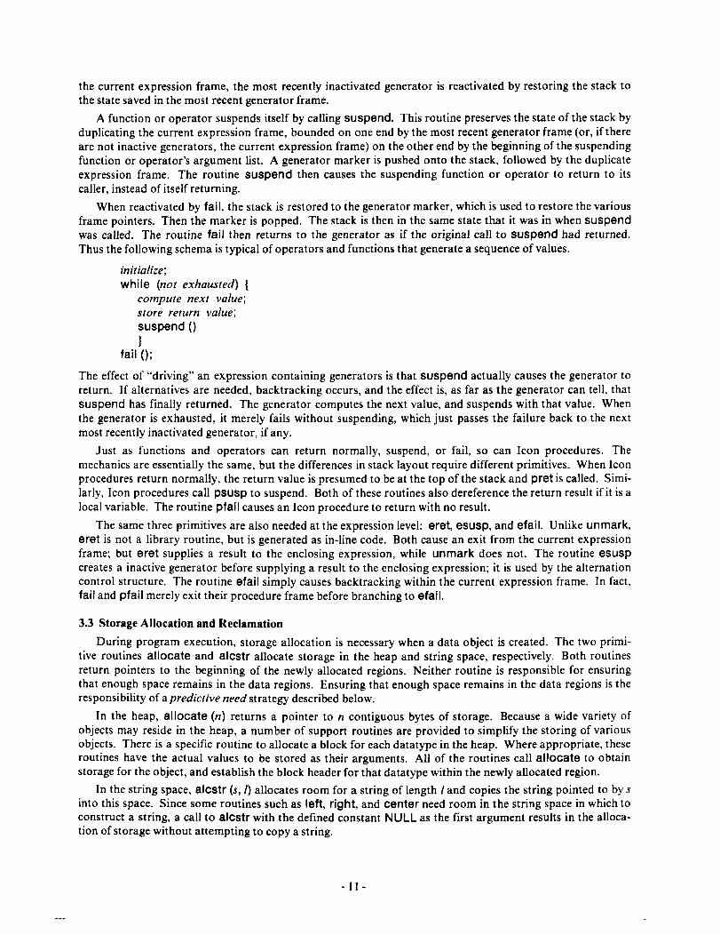


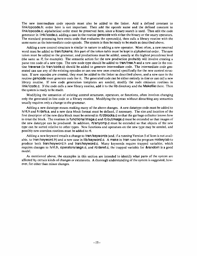


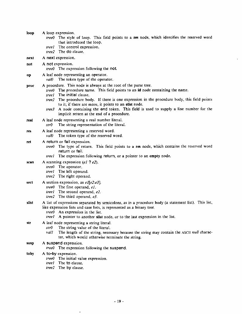

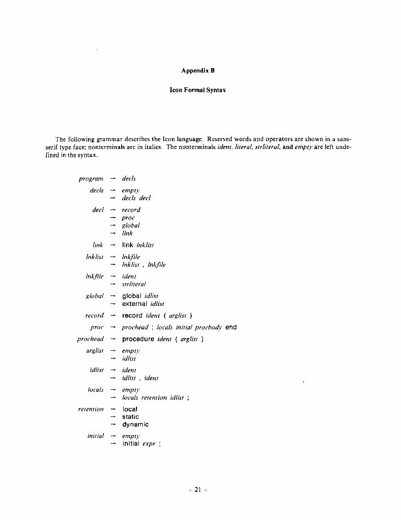

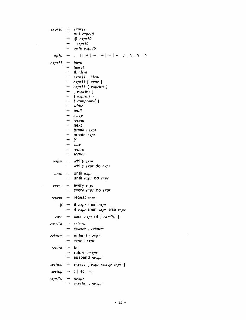

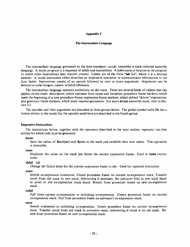
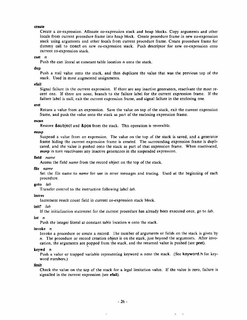

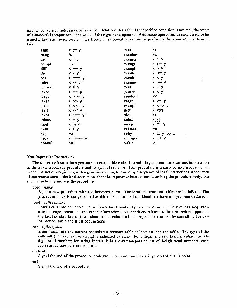


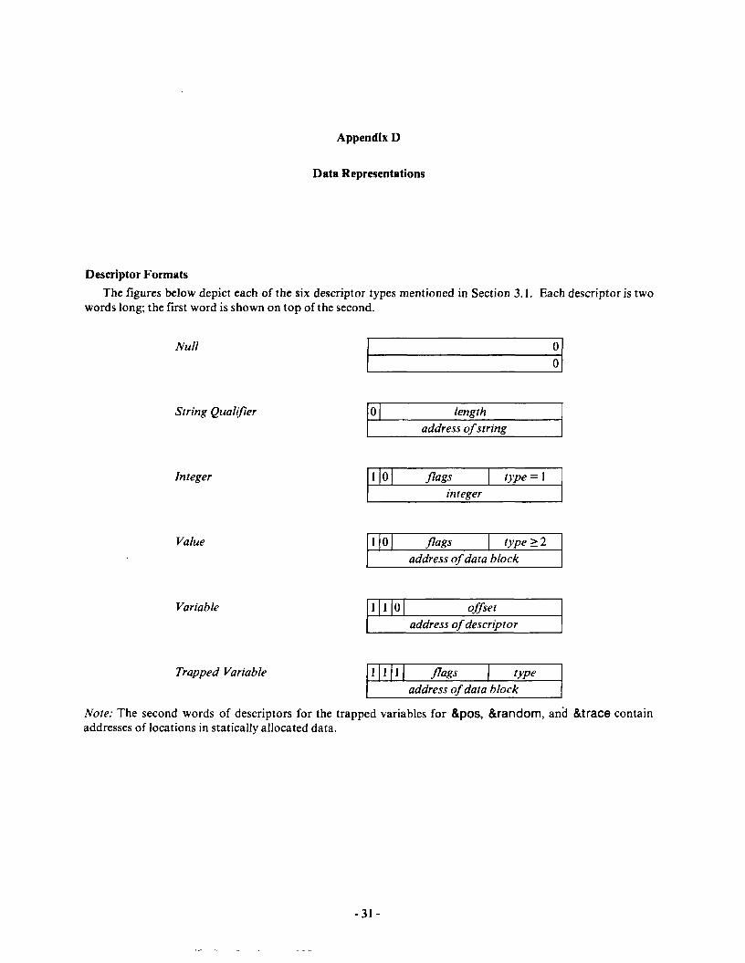
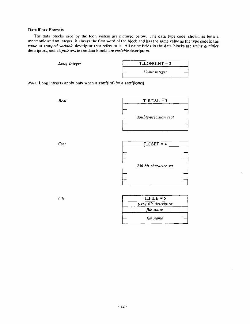
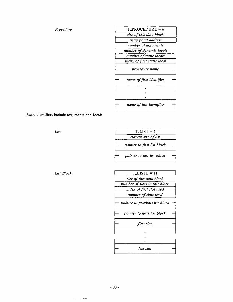
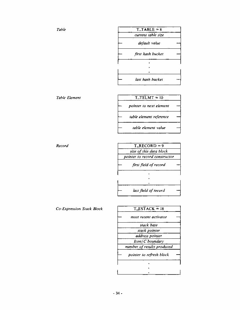


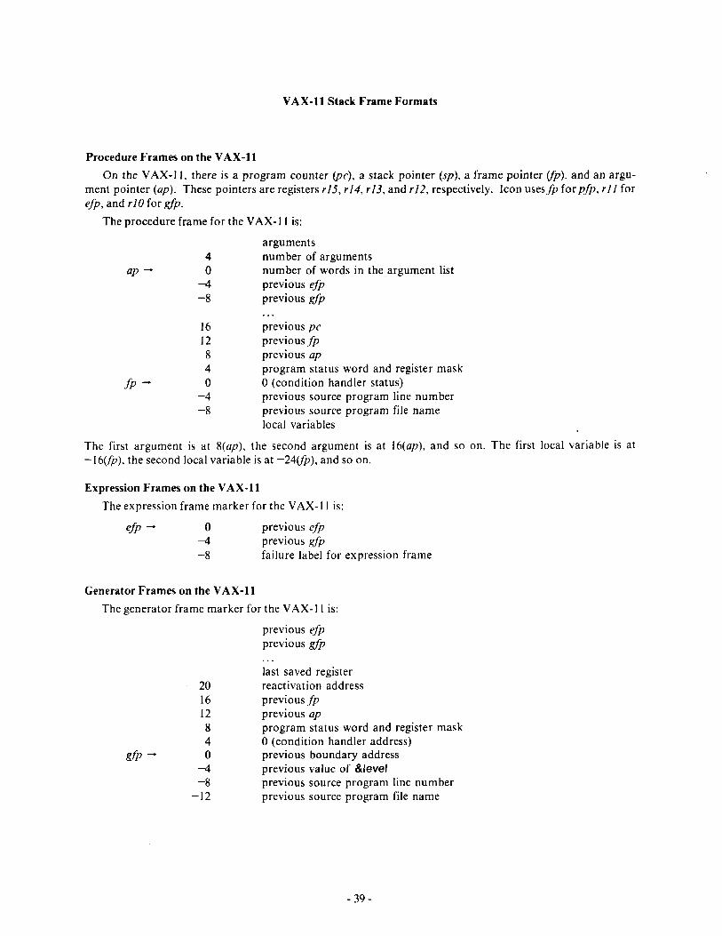

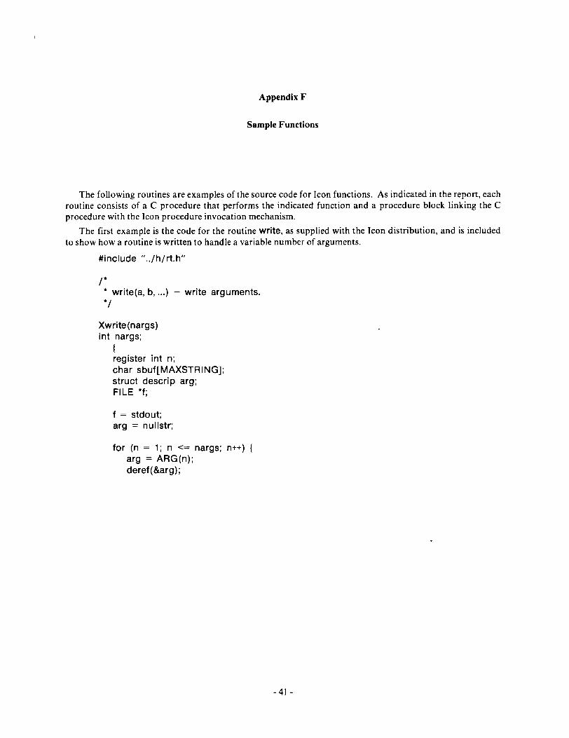


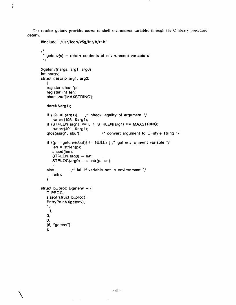


![[Lexical Analysis] - CSITauthority · This means less work for subsequent phases of the compiler. ... 1. Use lexical analyzer generator like flex that produces lexical analyzer from](https://static.documents.pub/doc/80x56/5af51f3b7f8b9a4d4d8e9caf/lexical-analysis-csitauthority-means-less-work-for-subsequent-phases-of-the.jpg)


