Pacific Northwest National Laboratory
Materials & Design Issues forJoining SiC Composites for Fusion
EnergyC.A. Lewinsohn and R.H. Jones
Pacific Northwest National LaboratoryRichland, WA, USA.
M. Singh H. SerizawaNASA Glenn Research Center JWRI Osaka University
Cleveland, OH, USA. Osaka University
T. Hinoki, Y. Katoh, and A. Kohyama T. ShibayamaIAE, Kyoto University CARET, Hokkaido University Kyoto, Japan Sapporo, Japan
D. CarnahanBusek Co., Inc
Natick, MA, USA
Pacific Northwest National Laboratory
Primary goals for the use ofSiC/SiC in fusion energy
X Low residual radioactivity to minimize:X risk to workersX contamination in the event of accidentsX environmental impact of waste disposal
X Mechanical reliabilityX Microstructural stability during irradiation of:
Y fibersY interphasesY matrix
XMinimal gaseous transmutationXHermetic behavior
Pacific Northwest National Laboratory
Critical materials requirements forjoining SiC/SiC for fusion energy
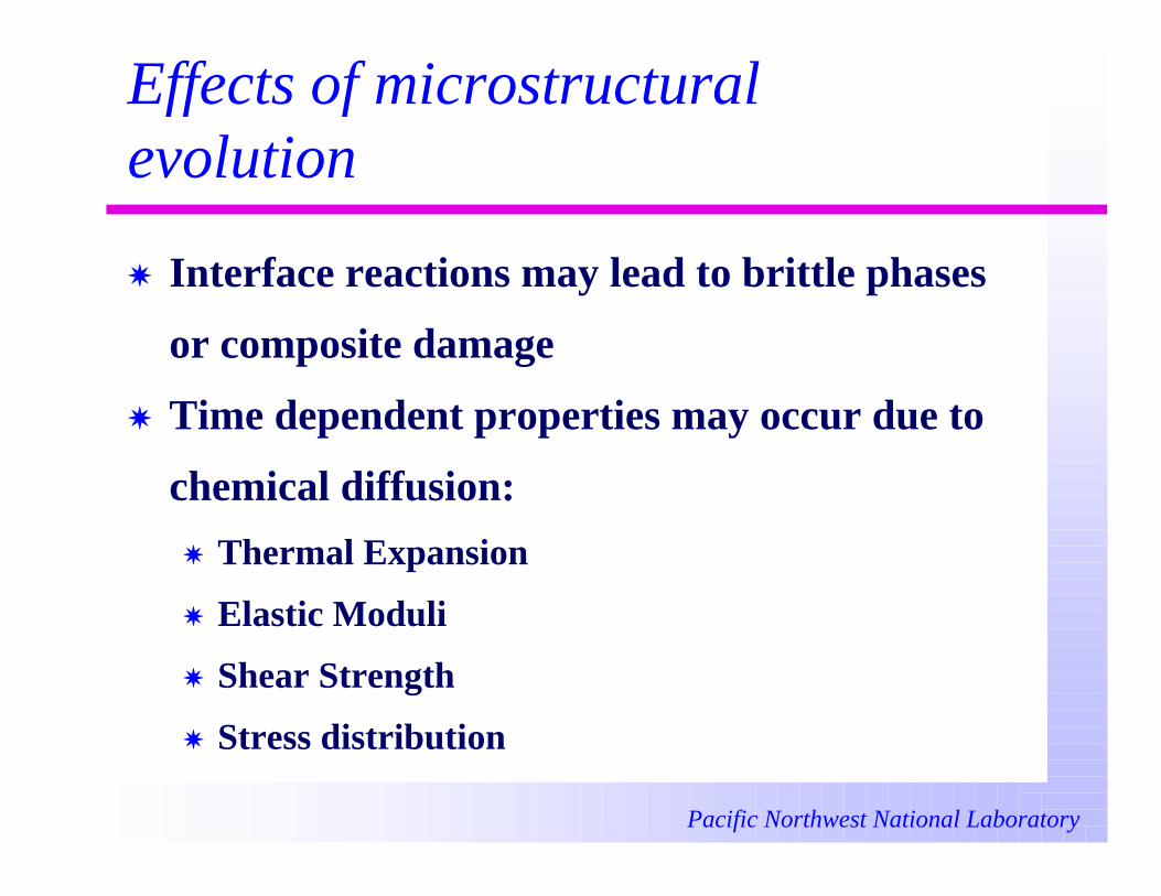
XMechanical properties
XThermal expansion match
XRadiation/Chemical stability
XThermal conductivity
XTime-dependent properties
XHermeticity
Pacific Northwest National Laboratory
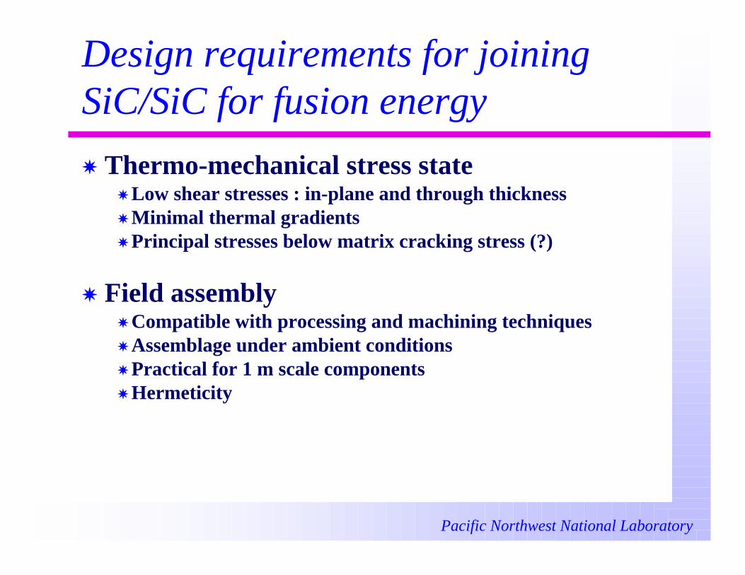
Design requirements for joiningSiC/SiC for fusion energy
X Thermo-mechanical stress stateX Low shear stresses : in-plane and through thicknessX Minimal thermal gradientsX Principal stresses below matrix cracking stress (?)
X Field assemblyX Compatible with processing and machining techniquesX Assemblage under ambient conditionsX Practical for 1 m scale componentsX Hermeticity
Pacific Northwest National Laboratory
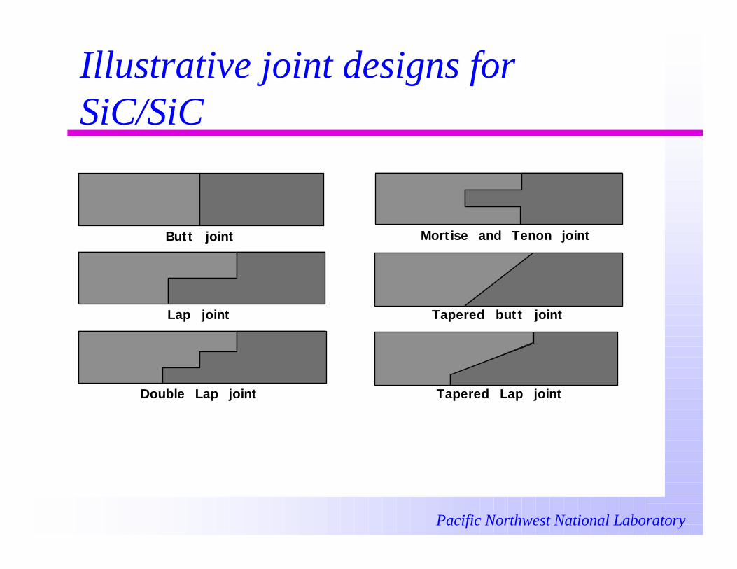
Illustrative joint designs forSiC/SiC
Butt joint
Lap joint
Double Lap joint
Mortise and Tenon joint
Tapered butt joint
Tapered Lap joint
Pacific Northwest National Laboratory
Some critical issues in jointdurability
For a given joint design:X Strength of joint material vs.matrix
X Stability of matrix and fibers
X Radiation effects on joint materials
X Thermal cycling effects
X Differential creep effects
Pacific Northwest National Laboratory
Physical parameters required formaterials R&DXStress-state
X Principal stresses, bending moments, shear stressesX Temporal behavior (fatigue, TMF)
XTemperatureX GradientsX Temporal behavior
XChemical environmentX Oxygen contentX He pressureX Coolant composition, temperature, pressure
XNeutron fluxXPlasma-surface interactions
X Particle momentumX Particle elastic properties
Pacific Northwest National Laboratory
Candidate joint materials for usein Fusion Energy Systems
X Melt infiltrated and reaction-formed siliconcarbide.
X Preceramic-polymer derived silicon carbide.
X Low-activation, high-temperature glasses.
X In-situ reinforced silicides.
X High-temperature brazes.
Pacific Northwest National Laboratory
Material studied
X Reaction Formed Silicon Carbide: silicon carbide
formed by reaction of a carbonaceous structure with
molten silicon or silicon alloys. Fabricated using the
ARCJoinT process developed at NASA Glenn Research
Center.
X Reaction Bonded Silicon Carbide: particulate silicon
carbide bonded by silicon carbide formed by reaction of
carbon powders with molten silicon. Fabricated by
BUSEK Co., Inc., Natick, MA.
Pacific Northwest National Laboratory
Material studied
X Substrates:
X Hexoloy SA: monolithic, sintered, alpha SiC.
Approximate grain size 2-3 m.
X Hi-Nicalon reinforced, CVI silicon carbide: 40 vol. %
fibers, 0/90º plain-weave.
Pacific Northwest National Laboratory
Interfacial reactions must bestudied
Long-term compatibility between joint materialand composites must be investigated
Pacific Northwest National Laboratory
Effects of microstructuralevolution
X Interface reactions may lead to brittle phases
or composite damage
X Time dependent properties may occur due to
chemical diffusion:
X Thermal Expansion
X Elastic Moduli
X Shear Strength
X Stress distribution
Pacific Northwest National Laboratory
Microscopy may be used toexamine interfacial reactions
Untreated joint appears micro-crystalline
Hexoloy(SiC)
Jointmaterial
Pacific Northwest National Laboratory
HRTEM used to determine phasedistributionIn practice, joints must be made in the field.
Joining conditions: 1250-1425 C5-10 minno external pressure
SiC C Interface Hexoloy SA
Control of spatial phase distribution may allowfunctional grading of thermomechanical properties.
(Selected area diffraction patterns [SADP])
Pacific Northwest National Laboratory
Mechanical Testing
Maximum TensileStress
4-pt bending
In-plane Shear Stress
Double-notch-shear in compression
Pacific Northwest National Laboratory
Mechanical Testing
not drawn to scale.
(center-line)
t d
h n
L
B
w
L
B
w
2
2
2
x
y
z
p q r s
Butt-joined flexural test specimen
45° Butt-joined flexural test specimen
Double-notch-shear specimen
Offset sandwich specimen
g
f
Pacific Northwest National Laboratory
Mechanical Testing
Through Thickness Shear StressAsymmetric 4-pt bending
Upper Fixture
Lower Fixture
roller/loadingpoint
x-y y
specimen
Pacific Northwest National Laboratory
Results: Flexural Strength
XFour-point bend strengths on the order of 200-300 MPa are commonly reported
0
50
100
150
200
250
300
350
400
Batch193 Batch194 Batch195 Batch196 Batch197NASA/PNL NASA/ALSienna33-20
Stre
ngth
(M
Pa)
DD
Pacific Northwest National Laboratory
Results: Flexural Strength
0.00
20.00
40.00
60.00
80.00
100.00
MaximumFlexuralStress(MPa)
reaction-formedSiC
(NASA)
reaction-formedSiC
(NASA)
reaction-bondedSiC
(Busek)
monolithic
monolithic
composite
XBond strengths for composite substrates werein the range of those for monolithic substrates.
Pacific Northwest National Laboratory
Results: Flexural Strength
XAdditional heat treatment improves flexuralstrength.
0
50
100
150
200
250
300
350
400
Hexoloy SA Joined by Reaction Bonded SiC1/4 Four-Point Bend Strength
Stre
ngth
(M
Pa)
Specimen Type
25°Cuntreated
25°C1100°C
100 h, Ar
1100°Cuntreated
Pacific Northwest National Laboratory
Results: Through-thickness shearstrength
0.00
20.00
40.00
60.00
80.00
100.00
maximumstress(MPa)
max.tensilestress
throughthickness
shear stress
reaction-formedSiC
reaction-formedSiC
cut ends
reaction-formedSiC
coated ends
Composite specimens
XThe value of the Through-Thickness ShearStrength was similar for composites joined at cut
surfaces or surfaces coated with CVD-SiC.
Pacific Northwest National Laboratory
Results
Substrate JointMaterial
Test Method Test Temp.(K)
JointThickness
(µm)
Strength(MPa)
RBSC RFSC 4PBS 298 10 210 + 6Hexoloy SA RFSC 4PBS 298 45-50 255 + 3.2Hexoloy SA RFSC 4PBS 298 52 53 + 6Hexoloy SA RBSC 4PBS 298 130 85 + 10SiCf/SiCm RFSC A4PB 298 115 28 + 7SiCf/SiCm RFSC 4PBS 298 115 78 + 8SiCf/SiCm RFSC 4PBS 298 125 65 + 5SiCf/SiCm RFSC 4PBS 1073 125 66 + 9SiCf/SiCm RFSC 4PBS 1473 125 59 + 7
RBSC = reaction-bonded silicon carbideRFSC = reaction-formed silicon carbide4PBS = 1/4, four-point bend strengthA4PB = assymmetrical, four-point bend strength
Pacific Northwest National Laboratory
SummaryXMaterials issues: radiation stability, physical properties,
hermeticity.XDesign issues: thermomechanical stresses, field assembly.XCritical issues: time-dependent properties, radiation effects,
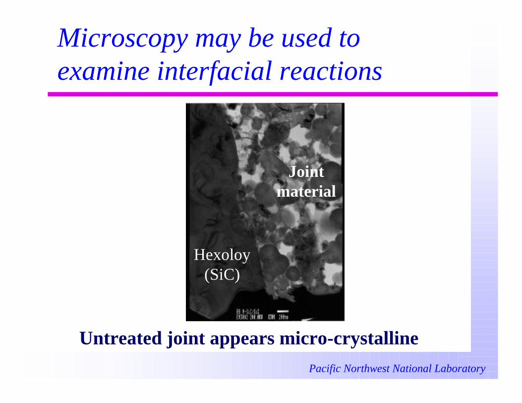
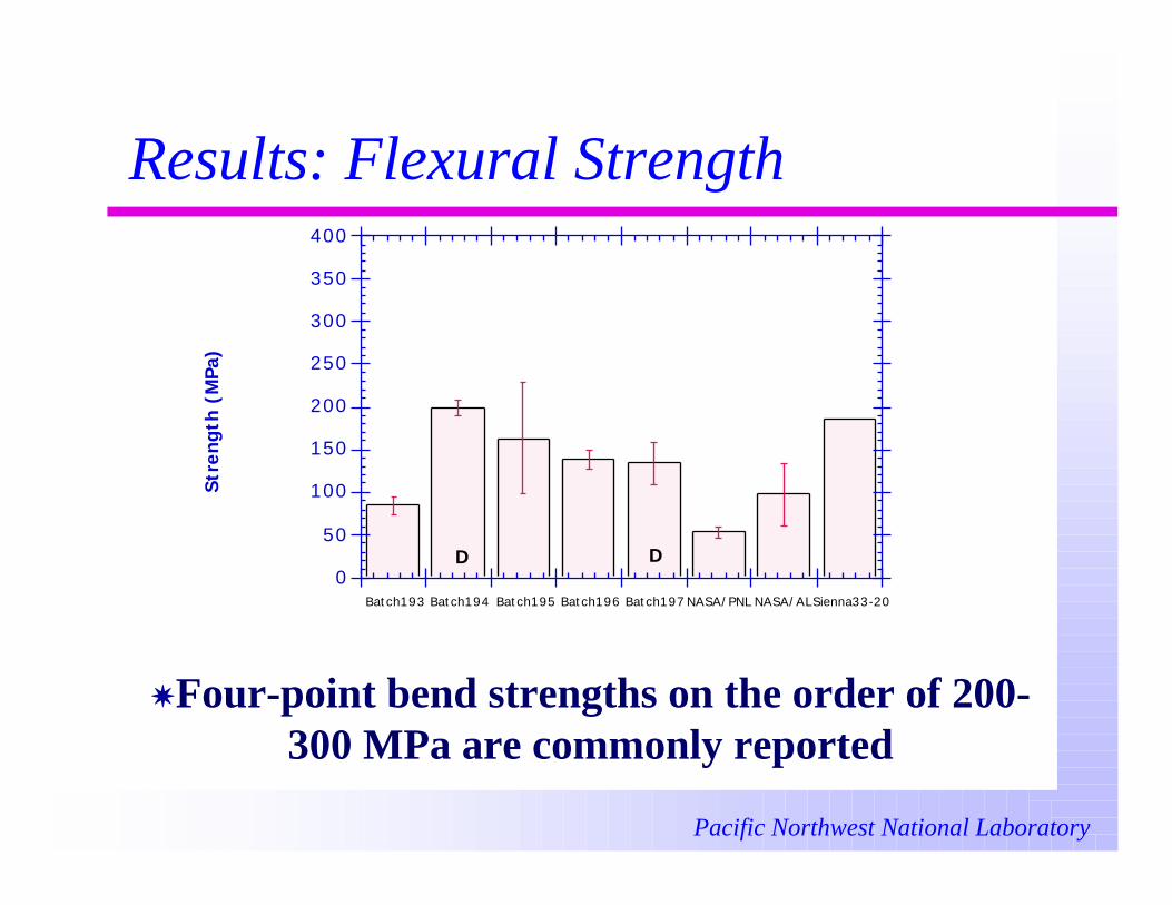
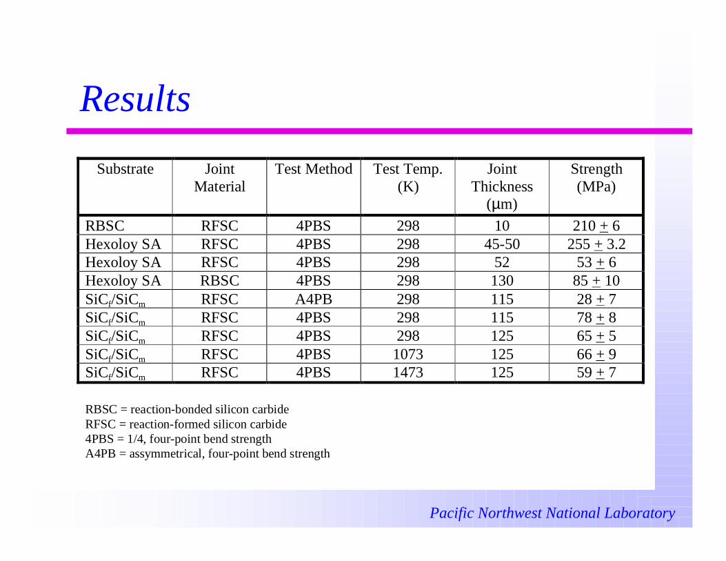
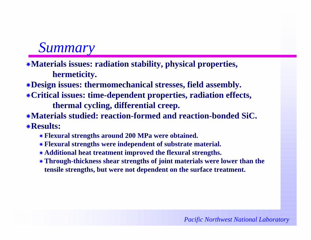
thermal cycling, differential creep.XMaterials studied: reaction-formed and reaction-bonded SiC.XResults:
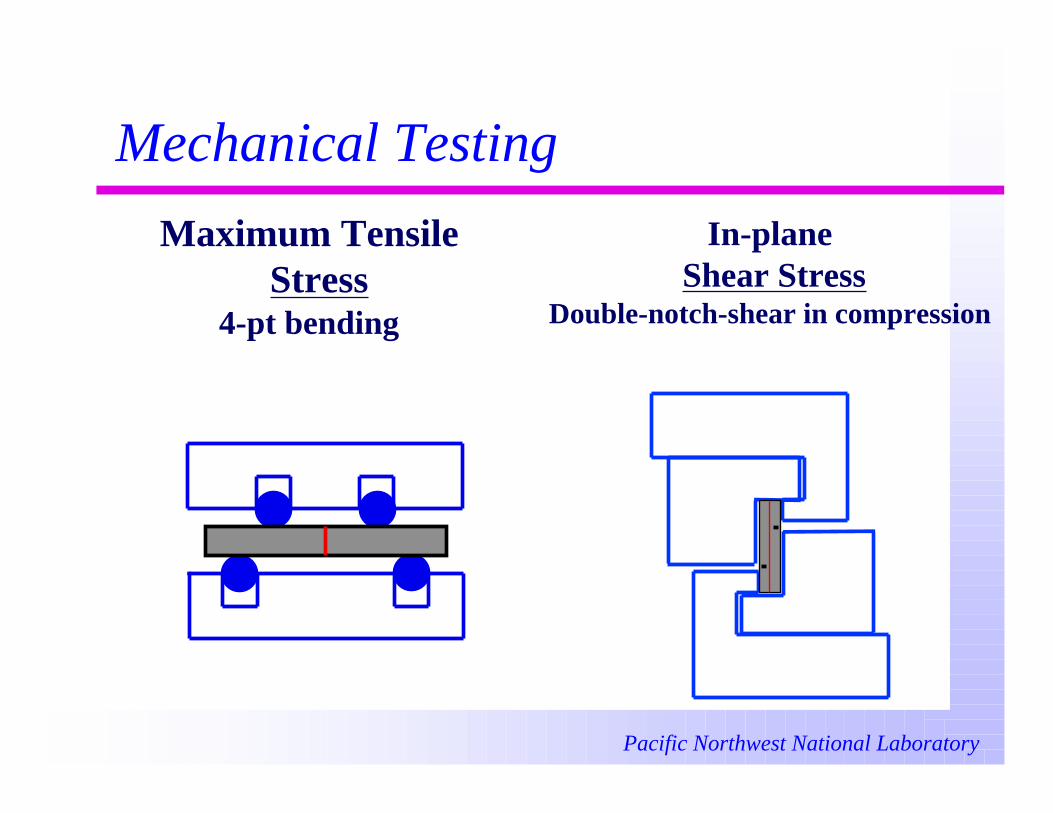
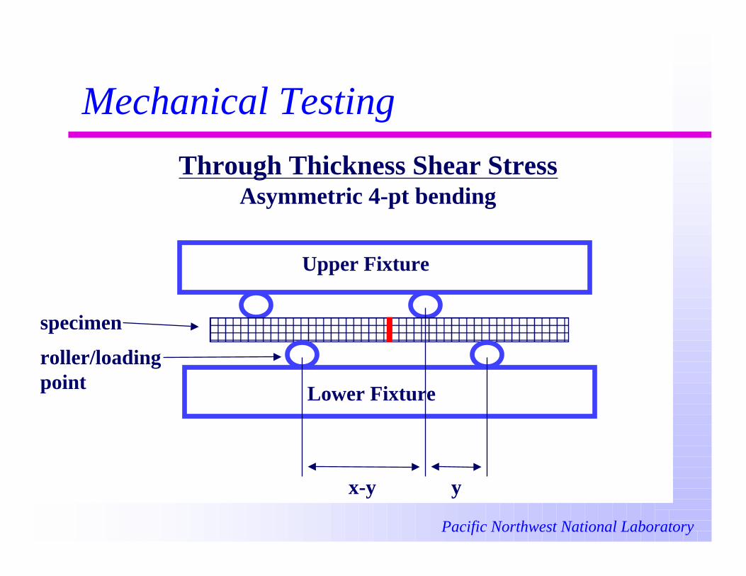
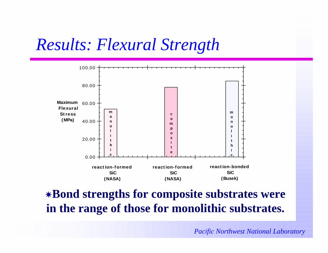
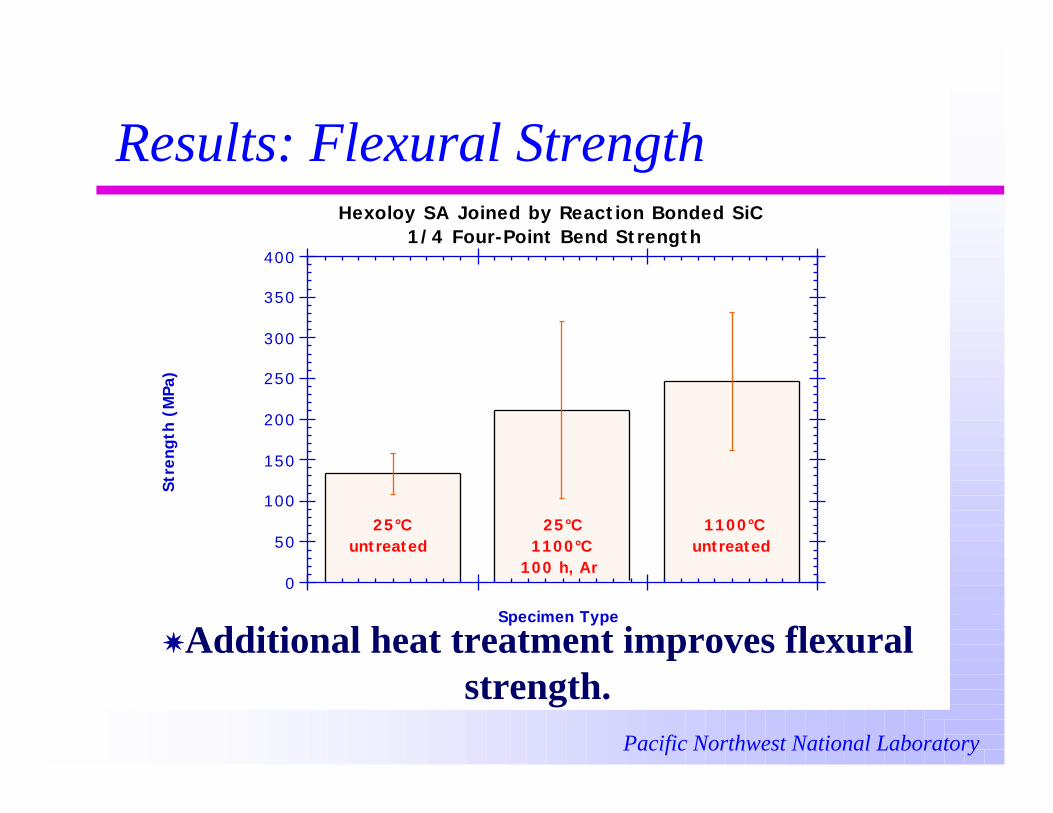
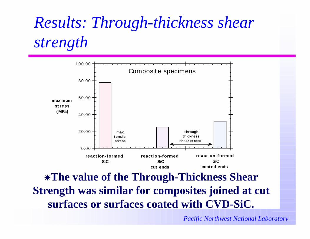
X Flexural strengths around 200 MPa were obtained.X Flexural strengths were independent of substrate material.X Additional heat treatment improved the flexural strengths.X Through-thickness shear strengths of joint materials were lower than the
tensile strengths, but were not dependent on the surface treatment.
Pacific Northwest National Laboratory
Future work
XOptimize joint processing conditions and thickness formechanical properties.
XStudy effects of thermal exposure and irradiation onmicrostructure and properties.
XEvaluate mechanical test methodology for irradiationstudies.
XInvestigate stress distribution in realistic jointgeometries via FEM modeling.