15
I Issue date: April 2011 TDK MLCC US Catalog Version B11 C Series High Q Capacitors Type: C0603 [EIA CC0201]

IIssue date: April 2011
TDK MLCCUS Catalog
Version B11
C SeriesHigh Q Capacitors
Type: C0603 [EIA CC0201]

RREMINDERSPlease read before using this product
SAFETY REMINDERS
TDK MLCC US Catalog Version B11Page 148
REMINDERS
1. If you intend to use a product listed in this catalog for a purpose that may cause loss of life or otherdamage, you must contact our company’s sales window.
2. We may modify products or discontinue production of a product listed in this catalog without priornotification.
3. We provide “Delivery Specification” that explain precautions for the specifications and safety of eachproduct listed in this catalog. We strongly recommend that you exchange these delivery specificationswith customers that use one of these products.
4. If you plan to export a product listed in this catalog, keep in mind that it may be a restricted item accordingto the “Foreign Exchange and Foreign Trade Control Law”. In such cases, it is necessary to acquire exportpermission in harmony with this law.
5. Any reproduction or transferring of the contents of this catalog is prohibited without prior permission fromour company.
6. We are not responsible for problems that occur related to the intellectual property rights or other rights ofour company or a third party when you use a product listed in this catalog. We do not grant license ofthese rights.
7. This catalog only applies to products purchased through our company or one of our company’s officialagencies. This catalog does not apply to products that are purchased through other third parties.

TDK MLCC US Catalog Version B11Page 149
C SeriesHigh Q CapacitorsType: C0603
Available Through Distribution Only*
Higher Q factor than standard capacitors High stability ith respect to ti e te perature
fre uency and voltage cellent attenuation High self-resonant fre uency Lo er po er dissipation less energy absorption Capacitance range of 0.2pF to 15pF Available in standard and tight tolerance Please contact TDK for Q values
AApplications High-fre uency applicationsPA modulesCellular communication, BluetoothCable/satellite TVGPS/satellite radioFilter networks/matching networksRF amplifiers/Low noise amplifiersVCOs, TCXOs, etc.DC blocking circuits
Features
Shape &Dimensions
Dimensions in mm
Part NumberConstruction
Series NameC 0603 C0G 1E 150 J T XXXX
Dimensions L x W (mm)
Temperature Characteristic
Rated Voltage (DC)
Nominal Capacitance (pF)
Capacitance Tolerance
Packaging StyleInternal Codes
L Body LengthW Body WidthT Body HeightB Terminal Width
Case Code Length WidthC0603 0.60 ± 0.03 0.30 ± 0.03
TemperatureCharacteristics
CapacitanceChange
TemperatureRange
C0G 0±30 ppm/ºC -55 to +125ºC
Voltage Code Voltage (DC)1E 25V
The capacitance is expressed in three digit codes and in units of picoFarads (pF). The first and second digits identify the first and second significant figures of the capacitance. The third digit identifies the multiplier. R designates a decimal point.
Capacitance Code Capacitance0R5 0.5pF010 1pF102 1,000pF (1nF)105 1,000,000pF (1μF)
Tolerance Code ToleranceW ± 0.05 pFB ± 0.10 pFC ± 0.25 pFD ± 0.50 pFE ± 0.20 pFG ± 2%J ± 5%
Packaging Code StyleT Tape & Reel
* This series is available through the distribution channel only. Please see www.tdk.com/distributor.php for a list of authorized distributors.
L Body LengthW Body WidthT Body HeightB Terminal Width

TDK MLCC US Catalog Version B11Page 150
* This series is available through the distribution channel only. Please see www.tdk.com/distributor.php for a list of authorized distributors.
CCapacitanceRange Chart C0603 [EIA CC0201]
Capacitance Range ChartTemperature Characteristics: C0G (0 ± 30ppm/ºC)Rated Voltage: 25V(1E)
0.30 mmStandard Thickness
CCapacitance((pF)
CapCode
TemperatureCharacteristics
Tolerance
W(±0.05)
B(±0.10pF)
C(±0.25pF)
D(±0.50pF)
E(±0.20pF)
G(±2%)
J(±5%)
0.2 0R2 -55 to 125ºC, 0±30 ppm/ºC0.3 0R3
0.4 0R40.5 0R50.6 0R60.7 0R70.8 0R80.9 0R9
1 0101.1 1R11.2 1R21.3 1R31.5 1R51.6 1R61.8 1R8
2 0202.2 2R22.4 2R42.7 2R7
3 0303.3 3R33.6 3R63.9 3R9
4 0404.3 4R34.7 4R7
5 0505.1 5R15.6 5R6
6 0606.2 6R26.8 6R8
7 0707.5 7R5
8 0808.2 8R2
9 0909.1 9R110 10011 11012 12013 13015 15016 16018 18020 200
TDK MLCC US Catalog Version B11Page 151
* This series is available through the distribution channel only. Please see www.tdk.com/distributor.php for a list of authorized distributors.
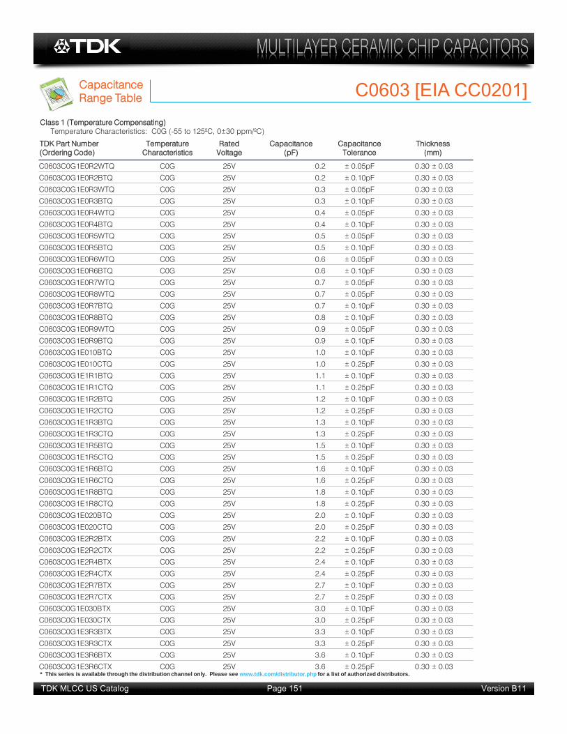
CCapacitanceRange Table C0603 [EIA CC0201]
TDK Part Number((Ordering Code)
TemperatureCharacteristics
RatedVoltage
Capacitance(pF)
CapacitanceTolerance
Thickness(mm)
C0603C0G1E0R2WTQ C0G 25V 0.2 ± 0.05pF 0.30 ± 0.03
C0603C0G1E0R2BTQ C0G 25V 0.2 ± 0.10pF 0.30 ± 0.03
C0603C0G1E0R3WTQ C0G 25V 0.3 ± 0.05pF 0.30 ± 0.03
C0603C0G1E0R3BTQ C0G 25V 0.3 ± 0.10pF 0.30 ± 0.03
C0603C0G1E0R4WTQ C0G 25V 0.4 ± 0.05pF 0.30 ± 0.03
C0603C0G1E0R4BTQ C0G 25V 0.4 ± 0.10pF 0.30 ± 0.03
C0603C0G1E0R5WTQ C0G 25V 0.5 ± 0.05pF 0.30 ± 0.03
C0603C0G1E0R5BTQ C0G 25V 0.5 ± 0.10pF 0.30 ± 0.03
C0603C0G1E0R6WTQ C0G 25V 0.6 ± 0.05pF 0.30 ± 0.03
C0603C0G1E0R6BTQ C0G 25V 0.6 ± 0.10pF 0.30 ± 0.03
C0603C0G1E0R7WTQ C0G 25V 0.7 ± 0.05pF 0.30 ± 0.03
C0603C0G1E0R8WTQ C0G 25V 0.7 ± 0.05pF 0.30 ± 0.03
C0603C0G1E0R7BTQ C0G 25V 0.7 ± 0.10pF 0.30 ± 0.03
C0603C0G1E0R8BTQ C0G 25V 0.8 ± 0.10pF 0.30 ± 0.03
C0603C0G1E0R9WTQ C0G 25V 0.9 ± 0.05pF 0.30 ± 0.03
C0603C0G1E0R9BTQ C0G 25V 0.9 ± 0.10pF 0.30 ± 0.03
C0603C0G1E010BTQ C0G 25V 1.0 ± 0.10pF 0.30 ± 0.03
C0603C0G1E010CTQ C0G 25V 1.0 ± 0.25pF 0.30 ± 0.03
C0603C0G1E1R1BTQ C0G 25V 1.1 ± 0.10pF 0.30 ± 0.03
C0603C0G1E1R1CTQ C0G 25V 1.1 ± 0.25pF 0.30 ± 0.03
C0603C0G1E1R2BTQ C0G 25V 1.2 ± 0.10pF 0.30 ± 0.03
C0603C0G1E1R2CTQ C0G 25V 1.2 ± 0.25pF 0.30 ± 0.03
C0603C0G1E1R3BTQ C0G 25V 1.3 ± 0.10pF 0.30 ± 0.03
C0603C0G1E1R3CTQ C0G 25V 1.3 ± 0.25pF 0.30 ± 0.03
C0603C0G1E1R5BTQ C0G 25V 1.5 ± 0.10pF 0.30 ± 0.03
C0603C0G1E1R5CTQ C0G 25V 1.5 ± 0.25pF 0.30 ± 0.03
C0603C0G1E1R6BTQ C0G 25V 1.6 ± 0.10pF 0.30 ± 0.03
C0603C0G1E1R6CTQ C0G 25V 1.6 ± 0.25pF 0.30 ± 0.03
C0603C0G1E1R8BTQ C0G 25V 1.8 ± 0.10pF 0.30 ± 0.03
C0603C0G1E1R8CTQ C0G 25V 1.8 ± 0.25pF 0.30 ± 0.03
C0603C0G1E020BTQ C0G 25V 2.0 ± 0.10pF 0.30 ± 0.03
C0603C0G1E020CTQ C0G 25V 2.0 ± 0.25pF 0.30 ± 0.03
C0603C0G1E2R2BTX C0G 25V 2.2 ± 0.10pF 0.30 ± 0.03
C0603C0G1E2R2CTX C0G 25V 2.2 ± 0.25pF 0.30 ± 0.03
C0603C0G1E2R4BTX C0G 25V 2.4 ± 0.10pF 0.30 ± 0.03
C0603C0G1E2R4CTX C0G 25V 2.4 ± 0.25pF 0.30 ± 0.03
C0603C0G1E2R7BTX C0G 25V 2.7 ± 0.10pF 0.30 ± 0.03
C0603C0G1E2R7CTX C0G 25V 2.7 ± 0.25pF 0.30 ± 0.03
C0603C0G1E030BTX C0G 25V 3.0 ± 0.10pF 0.30 ± 0.03
C0603C0G1E030CTX C0G 25V 3.0 ± 0.25pF 0.30 ± 0.03
C0603C0G1E3R3BTX C0G 25V 3.3 ± 0.10pF 0.30 ± 0.03
C0603C0G1E3R3CTX C0G 25V 3.3 ± 0.25pF 0.30 ± 0.03
C0603C0G1E3R6BTX C0G 25V 3.6 ± 0.10pF 0.30 ± 0.03
C0603C0G1E3R6CTX C0G 25V 3.6 ± 0.25pF 0.30 ± 0.03
Class 1 (Temperature Compensating)Temperature Characteristics: C0G (-55 to 125ºC, 0±30 ppm/ºC)

TDK MLCC US Catalog Version B11Page 152
* This series is available through the distribution channel only. Please see www.tdk.com/distributor.php for a list of authorized distributors.
CCapacitanceRange Table C0603 [EIA CC0201]
TDK Part Number((Ordering Code)
TemperatureCharacteristics
RatedVoltage
Capacitance(pF)
CapacitanceTolerance
Thickness(mm)
C0603C0G1E3R9BTX C0G 25V 3.9 ± 0.10pF 0.30 ± 0.03
C0603C0G1E3R9CTX C0G 25V 3.9 ± 0.25pF 0.30 ± 0.03
C0603C0G1E040BTX C0G 25V 4.0 ± 0.10pF 0.30 ± 0.03
C0603C0G1E040CTX C0G 25V 4.0 ± 0.25pF 0.30 ± 0.03
C0603C0G1E4R3BTX C0G 25V 4.3 ± 0.10pF 0.30 ± 0.03
C0603C0G1E4R3CTX C0G 25V 4.3 ± 0.25pF 0.30 ± 0.03
C0603C0G1E4R7BTX C0G 25V 4.7 ± 0.10pF 0.30 ± 0.03
C0603C0G1E4R7CTX C0G 25V 4.7 ± 0.25pF 0.30 ± 0.03
C0603C0G1E050BTX C0G 25V 5.0 ± 0.10pF 0.30 ± 0.03
C0603C0G1E050CTX C0G 25V 5.0 ± 0.25pF 0.30 ± 0.03
C0603C0G1E5R1BTX C0G 25V 5.1 ± 0.10pF 0.30 ± 0.03
C0603C0G1E5R1CTX C0G 25V 5.1 ± 0.25pF 0.30 ± 0.03
C0603C0G1E5R6BTX C0G 25V 5.6 ± 0.10pF 0.30 ± 0.03
C0603C0G1E5R6CTX C0G 25V 5.6 ± 0.25pF 0.30 ± 0.03
C0603C0G1E060BTX C0G 25V 6.0 ± 0.10pF 0.30 ± 0.03
C0603C0G1E060CTX C0G 25V 6.0 ± 0.25pF 0.30 ± 0.03
C0603C0G1E6R2BTX C0G 25V 6.2 ± 0.10pF 0.30 ± 0.03
C0603C0G1E6R2CTX C0G 25V 6.2 ± 0.25pF 0.30 ± 0.03
C0603C0G1E6R8BTX C0G 25V 6.8 ± 0.10pF 0.30 ± 0.03
C0603C0G1E6R8CTX C0G 25V 6.8 ± 0.25pF 0.30 ± 0.03
C0603C0G1E070BTX C0G 25V 7.0 ± 0.10pF 0.30 ± 0.03
C0603C0G1E070CTX C0G 25V 7.0 ± 0.25pF 0.30 ± 0.03
C0603C0G1E7R5BTX C0G 25V 7.5 ± 0.10pF 0.30 ± 0.03
C0603C0G1E7R5CTX C0G 25V 7.5 ± 0.25pF 0.30 ± 0.03
C0603C0G1E080BTX C0G 25V 8.0 ± 0.10pF 0.30 ± 0.03
C0603C0G1E080CTX C0G 25V 8.0 ± 0.25pF 0.30 ± 0.03
C0603C0G1E8R2BTX C0G 25V 8.2 ± 0.10pF 0.30 ± 0.03
C0603C0G1E8R2CTX C0G 25V 8.2 ± 0.25pF 0.30 ± 0.03
C0603C0G1E090BTX C0G 25V 9.0 ± 0.10pF 0.30 ± 0.03
C0603C0G1E090CTX C0G 25V 9.0 ± 0.25pF 0.30 ± 0.03
C0603C0G1E9R1BTX C0G 25V 9.1 ± 0.10pF 0.30 ± 0.03
C0603C0G1E9R1CTX C0G 25V 9.1 ± 0.25pF 0.30 ± 0.03
C0603C0G1E100ETX C0G 25V 10 ± 0.20pF 0.30 ± 0.03
C0603C0G1E100DTX C0G 25V 10 ± 0.50pF 0.30 ± 0.03
C0603C0G1E110GTX C0G 25V 11 ± 2% 0.30 ± 0.03
C0603C0G1E110JTX C0G 25V 11 ± 5% 0.30 ± 0.03
C0603C0G1E120GTX C0G 25V 12 ± 2% 0.30 ± 0.03
C0603C0G1E120JTX C0G 25V 12 ± 5% 0.30 ± 0.03
C0603C0G1E130GTX C0G 25V 13 ± 2% 0.30 ± 0.03
C0603C0G1E130JTX C0G 25V 13 ± 5% 0.30 ± 0.03
C0603C0G1E150GTX C0G 25V 15 ± 2% 0.30 ± 0.03
C0603C0G1E150JTX C0G 25V 15 ± 5% 0.30 ± 0.03
C0603C0G1E160GTX C0G 25V 16 ± 2% 0.30 ± 0.03
C0603C0G1E160JTX C0G 25V 16 ± 5% 0.30 ± 0.03
Class 1 (Temperature Compensating)Temperature Characteristics: C0G (-55 to 125ºC, 0±30 ppm/ºC)

TDK MLCC US Catalog Version B11Page 153
* This series is available through the distribution channel only. Please see www.tdk.com/distributor.php for a list of authorized distributors.
CCapacitanceRange Table C0603 [EIA CC0201]
TDK Part Number((Ordering Code)
TemperatureCharacteristics
RatedVoltage
Capacitance(pF)
CapacitanceTolerance
Thickness(mm)
C0603C0G1E180GTX C0G 25V 18 ± 2% 0.30 ± 0.03
C0603C0G1E180JTX C0G 25V 18 ± 5% 0.30 ± 0.03
C0603C0G1E200GTX C0G 25V 20 ± 2% 0.30 ± 0.03
C0603C0G1E200JTX C0G 25V 20 ± 5% 0.30 ± 0.03
Class 1 (Temperature Compensating)Temperature Characteristics: C0G (-55 to 125ºC, 0±30 ppm/ºC)

TDK MLCC US Catalog Version B11Page 154
GGeneralSpecifications C0603 Series – High Q Capacitors
No. Item Performance Test or Inspection Method
1 External Appearance
No defects which may affectperformance.
Inspect with magnifying glass (10 ).
2 Insulation Resistance
10,000M min. Apply rated voltage for 60s.
3 Voltage Proof Withstand test voltage without insulation breakdown or other damage.
Above DC voltage shall be applied for 1 to 5s. Charge / discharge current shall not exceed 50mA.
4 Capacitance Within the specified tolerance.
5 Q(Class 1)
C : Rated capacitance (pF)
See No.4 in this table for measuring condition.
6 Temperature Characteristicsof Capacitance(Class 1)
Capacitance driftWithin 0.2% or 0.05pF, whichever larger.
Temperature coefficient shall be calculated based on values at 25ºC and 85ºC temperature.
Measuring temperature below 20ºC shall be -10ºC and -25ºC.
7 Robustness of Terminations
No sign of termination coming off, breakage of ceramic, or other abnormal signs.
Reflow solder the capacitor on P.C. board (shown in Appendix 1) and apply a pushing force of 2N for 10 1s.
8 Bending No mechanical damage. Reflow solder the capacitor on P.C. board (shown in Appendix 2) and bend it for 1mm.
Class Apply voltageClass 1 3 rated voltage
ClassMeasuringFrequency
Measuring voltage
Class 1 1MHz±10% 0.5 - 5 Vrms
Rated Capacitance QC 30pF 1,000 min.C < 30pF 400 + 20 C min.
T.C. Temperature CoefficientC0G 0 30 ppm/ºC
Pushing force
P.C. boardCapacitor
1
2050
F
R230
45 45Unit: mm
* This series is available through the distribution channel only. Please see www.tdk.com/distributor.php for a list of authorized distributors.

TDK MLCC US Catalog Version B11Page 155
GGeneralSpecifications C0603 Series – High Q Capacitors
No. Item Performance Test or Inspection Method
9 Solderability New solder to cover over 75% oftermination.
25% may have pinholes or rough spots but not concentrated in one spot.
Ceramic surface of A sections shall not be exposed due to melting or shifting of termination material.
Completely soak both terminations in solder at 235 5ºC for 2 0.5s.
Solder: H63A (JIS Z 3282)
Flux: Isopropyl alcohol (JIS K 8839)Rosin (JIS K 5902) 25% solid solution.
10 Resistance to solder heat Completely soak both terminations in solder at 260 5ºC for 5 1s.
Preheating conditionTemp.: 150 10ºCTime : 1 to 2min.
Flux: Isopropyl alcohol (JIS K 8839)Rosin (JIS K 5902) 25% solid solution.
Solder: H63A (JIS Z 3282)
Leave the capacitor in ambient conditions for 6 to 24h before measurement.
External appearance
No cracks are allowed and terminations shall be covered at least 60% with new solder.
Capacitance
Q (Class 1)
C : Rated capacitance (pF)
InsulationResistance
Meet the initial spec.
Voltage Proof
No insulation breakdown or other damage.
11 Vibration Reflow solder the capacitor on P.C. board (shown in Appendix 1) before testing.
Vibrate the capacitor with amplitude of 1.5mm P-P sweeping the fre uencies from 10Hz to 55Hz and back to 10Hz after 1min.
Repeat this for 2h each in 3 perpendicular directions.
External appearance
No mechanical damage.
Capacitance
Q (Class 1)
C : Rated capacitance (pF)
A section
Characteristics Change from the value before test
Class 1 C0G Capacitance drift within 2.5% or 0.25pF,
whichever larger.
Rated Capacitance QC 30pF 1,000 min.C < 30pF 400 + 20 C min.
Characteristics Change from the value before test
Class 1 C0G Capacitance drift within 2.5% or 0.25pF,
whichever larger.
Rated Capacitance QC 30pF 1,000 min.C < 30pF 400+20 C min.
* This series is available through the distribution channel only. Please see www.tdk.com/distributor.php for a list of authorized distributors.

TDK MLCC US Catalog Version B11Page 156
GGeneralSpecifications C0603 Series – High Q Capacitors
No. Item Performance Test or Inspection Method
12 Temperature cycle Reflow solder the capacitors on a P.C. board (shown in Appendix 1) before testing.
Expose the capacitor in the conditions in step 1 through step 4, and repeat 5 times consecutively.
Leave the capacitor in ambient conditions for 6 to 24h before measurement.
Externalappearance
No mechanical damage.
Capacitance
Q (Class 1)
C : Rated capacitance (pF)
InsulationResistance
Meet the initial spec.
Voltage Proof
No insulation breakdown or other damage.
13 Moisture Resistance (Steady State) Reflow solder the capacitor on P.C. board (shown in Appendix 1) before testing.
Leave at temperature 40 2ºC, 90 to 95%RH for 500 +24,0h.
Leave the capacitor in ambient condition for 6 to 24h before measurement.
External appearance
No mechanical damage.
Capacitance
Q (Class 1)
C : Rated capacitance (pF)
InsulationResistance
1,000M min.
Characteristics Change from the value before test
Class 1 C0G Capacitance drift within 2.5% or 0.25pF,
whichever larger.
Rated Capacitance QC 30pF 1,000 min.C < 30pF 400 + 20 C min.
Step Temperature (ºC) Time (min.)1 Min. operating temp. 3 30 ± 32 Reference Temp. 2 – 53 Max. operating temp. 2 30 ± 24 Reference Temp. 2 - 5
Characteristics Change from the value before test
Class 1 C0G Capacitance drift within 5% or 0.5pF,
whichever larger.
Rated Capacitance QC 30pF 350 min.10pF C < 30pF 275 + 5/2 C min.C < 10pF 200 + 10 C min.
* This series is available through the distribution channel only. Please see www.tdk.com/distributor.php for a list of authorized distributors.
TDK MLCC US Catalog Version B11Page 157
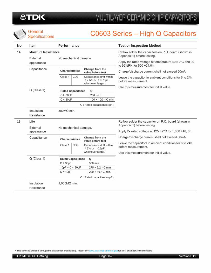
GGeneralSpecifications C0603 Series – High Q Capacitors
No. Item Performance Test or Inspection Method
14 Moisture Resistance Reflow solder the capacitors on P.C. board (shown in Appendix 1) before testing.
Apply the rated voltage at temperature 40 2ºC and 90 to 95%RH for 500 +24,0h.
Charge/discharge current shall not exceed 50mA.
Leave the capacitor in ambient conditions for 6 to 24h before measurement.
Use this measurement for initial value.
Externalappearance
No mechanical damage.
Capacitance
Q (Class 1)
C : Rated capacitance (pF)
InsulationResistance
500M min.
15 Life Reflow solder the capacitor on P.C. board (shown in Appendix 1) before testing.
Apply 2x rated voltage at 125 2ºC for 1,000 +48, 0h.
Charge/discharge current shall not exceed 50mA.
Leave the capacitors in ambient condition for 6 to 24h before measurement.
Use this measurement for initial value.
External appearance
No mechanical damage.
Capacitance
Q (Class 1)
C : Rated capacitance (pF)
InsulationResistance
1,000M min.
Characteristics Change from the value before test
Class 1 C0G Capacitance drift within 7.5% or 0.75pF,
whichever larger.
Rated Capacitance QC 30pF 200 min.C < 30pF 100 + 10/3 C min.
Characteristics Change from the value before test
Class 1 C0G Capacitance drift within 3% or 0.3pF,
whichever larger.
Rated Capacitance QC 30pF 350 min.10pF C < 30pF 275 + 5/2 C min.C < 10pF 200 + 10 C min.
* This series is available through the distribution channel only. Please see www.tdk.com/distributor.php for a list of authorized distributors.

TDK MLCC US Catalog Version B11Page 158
GGeneralSpecifications C0603 Series – High Q Capacitors
Appendix - 1aP.C. Board for reliability test
Applied for C0603, C1005, C1608, C2012, C3216
Appendix - 2aP.C. Board for bending test
Applied for C0603, C1005
100 mm
Solder Resist Copper
b a
c
40 m
m 1.0
mm
c
a
b
Solder resist
b
100 mm
Copper
40 m
m
Material : Glass Epoxy ( As per JIS C6484 GE4 )
P.C. Board thickness : Appendix - 2 0.8mm
Appendix - 1 1.6mm
Copper ( thickness 0.035mm )Solder resist
Case Code Dimensions (mm)JIS EIA a b c
C0603 CC0201 0.3 0.8 0.3
* This series is available through the distribution channel only. Please see www.tdk.com/distributor.php for a list of authorized distributors.

TDK MLCC US Catalog Version B11Page 159
SSolderingInformation C0603 Series – High Q Capacitors
Reflow Soldering Unit: mm
TypeSymbol
C0603[CC0201]
A 0.25 ~ 0.35B 0.2 ~ 0.3C 0.25 ~ 0.35
Recommended Soldering Land Pattern Recommended Soldering Profile
AB
C
Chip capacitor Solder land
Solder resist
Excessive solder
Higher tensile force on the chip capacitor may cause cracking.
Ade uate solder
Insufficient solder
Small solder fillet may cause contact failure or failure to hold the chip capacitor to the P.C. board.
Recommended Solder Amount
Recommended soldering duration
Temp./Dura.
Solder
Reflow SolderingPeak temp
(°C)Duration
(sec.)Sn-Pb Solder 230 max. 20 max.
Lead-Free Solder 260 max. 10 max.
Recommended solder compositionsSn-37Pb (Sn-Pb solder)Sn-3.0Ag-0.5Cu (Lead Free Solder)
Preheating Condition
Soldering Temp. (ºC)
Reflow soldering T 150Manual soldering T 150
Maximum amountMinimum amount
Reflow Soldering Manual soldering (Solder iron)
T
Preheating
3sec. (As short as possible)
0
300
Tem
p (º
C)
Tem
p (º
C)
0
T
Soldering Natural coolingPreheating
Peak Temp
Over 60 sec.
Peak Temp time
* This series is available through the distribution channel only. Please see www.tdk.com/distributor.php for a list of authorized distributors.

TDK MLCC US Catalog Version B11Page 160
PPackagingInformation C0603 Series – High Q Capacitors
CCarrier Tape Configuration
CChip Quantity Per Reel and Structure of Reel
PPeel Back Force (Top Tape)
Carrier tape shall be flexible enough to be wound around a minimum radius of 30mm with components in tape. The missing of components shall be less than
0.1% Components shall not stick to the cover tape. The cover tape shall not protrude beyond the
edges of the carrier tape and shall not cover the sprocket holes.
Paper carrier tape
Pitch hole
Top cover tape
Bottom cover tape(Bottom cover tape is not always applied)
Paper Carrier Tape & Reel
Case Code Chip Thickness
(mm)
Taping Material
Chip quantity (pcs.)
JIS EIA
C0603 CC0201 0.30 Paper 15,000
Carrier tapeTop cover tape
Direction & angle of pull
0.05 – 0.7 N
0~15
Bottom cover tape (Paper carrier tape)
Direction of pull force
Drawing directionLeader
400mm min
Bulk160mm min.
Chips Bulk160mm min
* This series is available through the distribution channel only. Please see www.tdk.com/distributor.php for a list of authorized distributors.

TDK MLCC US Catalog Version B11Page 161
AddditionalInformation C0603 Series – High Q Capacitors
SShape & Dimensions
TDK Corporation established internal product environmental assurance standards that include the six hazardous substances banned by the EU RoHS Directive1 enforced on July 1, 2006 along with additional substances independently banned by TDK and has successfully completed making general purpose electronic components conform to the RoHS Directive2.
L
BG
BW
T
Terminal electrode
Ceramic dielectricInternal electrode
34
5
1 2
No. NAME MATERIALClass 1
(1) Ceramic Dielectric CaZrO3
(2) Internal Electrode Nickel (Ni)(3)
TerminationCopper (Cu)
(4) Nickel (Ni)(5) Tin (Sn)
IInside Structure & Material System
Case Code Dimensions (mm)JIS EIA L W T B G
C0603 CC0201 0.60 0.30 0.30 0.15 0.20 min.
EEnvironmental Information
1. Abbreviation for Restriction on Hazardous Substances, which refers to the regulation EU Directive 2002/95/EC on hazardous substances by the European Union (EU) effective from July 1, 2006. The Directive bans the use of six specific hazardous substances in electric and electronic devices and products handled within the EU. The six substances are lead, mercury, cadmium, hexavalent chromium, PBB (polybrominated biphenyls), and PBDE (polybrominated diphenyl ethers).
2. This means that, in conformity with the EU Directive 2002/95/EC, lead, cadmium, mercury, hexavalentchromium, and specific bromine-based flame retardants, PBB and PBDE, have not been used, except for exempted applications.
For REACH (SVHC : 15 substances according to ECHA / October 2008) : All TDK MLCC do not contain these 15 substances.
For European Directive 2000/53/CE and 2005/673/CE : Cadmium, Hexavalent Chromium, Mercury, Lead are not contained in all TDK MLCC.
For European Directive 2003/11/CE : Pentabromodiphenyl-ether, Octabromodiphenyl-ether are not contained in all TDK MLCC.
* This series is available through the distribution channel only. Please see www.tdk.com/distributor.php for a list of authorized distributors.


