74
Operator/Service & Parts Manual First Edition Rev A1 Part No. 833008 T25/T45

Operator/Service & Parts Manual
First Edition
Rev A1
Part No. 833008
T25/T45
Operating Instructions and Parts Manual
2 Terex T25I and T45I Super Quiet Generator
June 2006REV A
Table Of Contents
INTRODUCTION ......................................................................................... 5DESCRIPTION OF EQUIPMENT................................................................ 5GENERAL SAFETY.................................................................................... 6SAFETY SIGN LOCATIONS ...................................................................... 7RECEIPT OF DELIVERY CHECKLIST..................................................... 10TRANSPORT & TOWING ......................................................................... 11SETUP ...................................................................................................... 11OPERATING INSTRUCTIONS ................................................................. 13MAINTENANCE ........................................................................................ 19TROUBLESHOOTING GUIDE.................................................................. 22ELECTRICAL TROUBLESHOOTING ...................................................... 27T25I / T45I SPECIFICATIONS AND DIMENSIONS.................................. 37TORQUE SPECIFICATIONS .................................................................... 39GENERATOR TORQUE SPECIFICATIONS ............................................ 39SERVICE PARTS FAX ORDER FORM .................................................... 41PARTS CATALOG ................................................................................... 43CABINET DECALS................................................................................... 44SAFETY DECALS .................................................................................... 45FIGURE 1 - BASE W/FUEL TANK ........................................................... 46FIGURE 2 - BASE W/LIFTING EYE & BATTERY .................................... 48FIGURE 3 - GENSET ................................................................................ 50FIGURE 4 - CABINET ASSEMBLY .......................................................... 52FIGURE 5 - CABINET ASSEMBLY W/DOORS ....................................... 54FIGURE 6 - CONTROL PANEL ASSEMBLY- UPPER............................. 56FIGURE 7 - CONTROL PANEL ASSEMBLY - LOWER........................... 58FIGURE 8 - DISTRIBUTION PANEL ........................................................ 60FIGURE 9 - MUFFLER ASSEMBLY......................................................... 62

Terex T25I and T45I Super Quiet Generator 3
Operating Instructions and Parts Manual
June 2006REV A
Table Of Contents
FIGURE 10 - AIR CLEANER ASSEMBLY ............................................... 64FIGURE 11A - ENGINES - T25I................................................................ 66FIGURE 11B - ENGINES - T45I................................................................ 68FIGURE 12 - VOLTAGE SELECTOR SWITCH ........................................ 70FIGURE 13 - TRAILER ............................................................................. 72FIGURE 14 - OPTIONS............................................................................. 74

Operating Instructions and Parts Manual
4 Terex T25I and T45I Super Quiet Generator
June 2006REV A
TEREX Model Number _____________________ Serial Number ____________________________
Engine Model Number______________________ Serial Number ____________________________
Generator Model Number ___________________ Serial Number ____________________________
Owner:__________________________________ Ship to: _________________________________
Options: _________________________________
_______________________________________
_______________________________________
_______________________________________
_______________________________________
P.O. Box 3147 (29732)590 Huey Road
Rock Hill, SC 29730Telephone: (800) 433-3026
FAX: (803) 366-1101
This Operation and Service Manual contains information specifically pertaining to the operation andmaintenance of the TEREX T25I and T45I Super Quiet Generators. We suggest that you read thismanual carefully prior to operating the generator. This manual should be retained and refered to foroperation, maintenance and ordering parts. When ordering parts, PLEASE INCLUDE THE MODEL ANDSERIAL NUMBER located on the nameplate of the generator . For major repair and service or otherinformation, contact your TEREX dealer, or call or write to:

Terex T25I and T45I Super Quiet Generator 5
Operating Instructions and Parts Manual
June 2006REV A
INTRODUCTION
Owners, Users, and Operators:TEREX appreciates your choice of our product foryour application. Our number one priority is usersafety which is best achieved by our joint efforts.We feel that you can make a major contribution tosafety if you as the equipment users and opera-tors:
• Comply with OSHA, Federal, State, and LocalRegulations.
• Read, Understand, and Follow theinstructions in this and other manuals suppliedwith this product.
• Use Good, Safe Work Practices in a commonsense way.
• Only have trained operators — directed byinformed and knowledgeable supervision —operating this product.
If there is anything in this manual that is not clearor which you believe should be added, pleasesend your comments to TEREX Service Depart-ment in Rock Hill, SC.
DESCRIPTION OF EQUIPMENT
The engine/generator assembly consists of adiesel engine combined with an electrical genera-tor. This assembly is firmly bolted together to forman integral unit and does not require anythingother than routine maintenance.
The engine is equipped with a 12-volt starter (24-volt starter optional) and can be wired for remotestarting capability at the control panel.
A dry-element air cleaner is standard equipment toensure a clean air supply, and a remote fuel/waterseparator is included for additional fuel systemprotection.
A governor on the engine provides a stableoperating speed under varying load conditions,and the generator is equipped with a solid-statevoltage regulator to stabilize the output voltageunder these same conditions. Figures andschematics of both the governor and regulator areprovided in the ENGINE and GENERATOROPERATOR’S MANUALS.
An automatic shutdown system is incorporated inthe generator set to sense low oil pressure and/orhigh coolant temperature, and in either case theengine/generator assembly will automaticallycease operation.
A diesel fuel tank is incorporated within the baseof the unit to ensure an uninterrupted operatingcycle under full load. The engine/generatorassembly is mounted to the base using highdurometer vibration isolators.
The enclosure for the generator set is constructedfrom 12 or 14-gauge sheet metal to ensuremaximum rigidity, and is bolted together to alloweasy access to major components if necessary.Four lockable, hinged access doors are providedfor routine operation and maintenance.
The enclosure on the Super Quiet Generator isspecifically designed for a high degree of soundattenuation. This allows the generator set to beoperated in noise-sensitive environments. Theinterior of the enclosure is coated with sound-dampening polymer foam that is highly effective innoise suppression and is impervious to water, fuel,and oil.
A high ambient temperature radiator and a criticalgrade exhaust silencer are contained within the
THE SAFETY ALERT SYMBOL IS USED TOALERT YOU TO POTENTIAL PERSONALINJURY HAZARDS. OBEY ALL SAFETYMESSAGES THAT FOLLOW THIS SYMBOLTO AVOID POSSIBLE INJURY OR DEATH.

Operating Instructions and Parts Manual
6 Terex T25I and T45I Super Quiet Generator
June 2006REV A
GENERAL SAFETY
HAZARD CLASSIFICATION
A multi-tier hazard classification system is used tocommunicate potential personal injury hazards.The following signal words used with the safetyalert symbol indicate a specific level of severity ofthe potential hazard. Signal words used withoutthe safety alert symbol relate to property damageand protection only. All are used as attention-getting devices throughout this manual as well ason decals and labels fixed to the machinery toassist in potential hazard recognition and preven-tion.
Red - Indicates animminently hazardous
situation which, if not avoided, will result in deathor serious injury.
Orange - Indicates apotentially hazardous
situation which, if not avoided, could result indeath or serious injury.
Yellow with safety alertsymbol - Indicates a
potentially hazardous situation which, if notavoided, may result in minor or moderate injury.
Yellow without safetyalert symbol - Indicates a
situation which, if not avoided, may result inproperty or equipment damage.
Green - Indicates impor-tant installation, operation
or maintenance information.
Hazardous voltage. Will causeserious injury or death.
Hot exhaust. Can contain carbonmonoxide. Will cause serious injuryor death.
Read all manuals that shipped withyour equipment. Maintenance isdone more easily and safely whenyou know what you're doing.
Keep all guards in place.
Wear hearing protection when youare near this equipment.
Lockout and Tagout. Equipment maybe energized. Lockout and tagout allenergy sources prior to performingmaintenance adjustments.
enclosure as standard equipment.
A center-point lifting attachment is located in thetop of the enclosure to allow crane lifting of theentire unit.
The generator set is mounted on a trailer equippedfor highway operation. Hydraulic surge brakes arestandard on larger generator sets for maximumstopping efficiency. Electric brakes are alsoavailable as an option.
DESCRIPTION OF EQUIPMENT (Cont.)

Terex T25I and T45I Super Quiet Generator 7
Operating Instructions and Parts Manual
June 2006REV A
GENERAL SAFETY (Cont.)
SAFETY SIGN LOCATIONS

Operating Instructions and Parts Manual
8 Terex T25I and T45I Super Quiet Generator
June 2006REV A
EXHAUST GASES ARE TOXIC. DO NOT USEINDOORS UNLESS PROPERLY VENTILATEDOR AN EXHAUST SCRUBBER IS USED.
Check exhaust system regularly for leaks andensure that the exhaust manifolds are secure andnot warped. Make sure the unit is well ventilated.
GENERAL SAFETY (Cont.)
Use protective clothing and safety equipment.Always wear approved safety equipment such asgloves, safety boots, safety hard hat, goggles, earprotection, and dust masks when necessary.Wear protective clothing that is snug and beltedwhere required.
UNAUTHORIZED WELDING
UNAUTHORIZED WELDING CAN CAUSESTRUCTURAL FAILURE OR PERSONALINJURY.
DO NOT weld on any structural member.
Any unauthorized welding or repair procedurewill void the warranty.
ACCIDENT PREVENTION
ALWAYS handle fuel with care. It is highlyflammable.
ALWAYS stop engine before refueling. Fillfuel tank outdoors.
DO NOT replace fuel lines with materialsdifferent from those supplied as originalequipment.
FIRES CAN CAUSE SEVERE PERSONALINJURY OR MACHINE DAMAGE.
Prevent fires by keeping the generator and itssurrounding area clean.
DO NOT refuel while smoking or when nearopen flame or sparks.
DO NOT refuel the engine when it is hot.Allow to cool for several minutes beforerefueling.
DO NOT spill fuel inside the engine compartment.If fuel has leaked, wipe it up and have leakrepaired before next use.
ALWAYS Have a fire extinguisher nearby. Besure theextinguisher is properly maintained and befamiliar with its use. Extinguishers rated ABCby the NFPA are appropriate for all applications.
FUELING

Terex T25I and T45I Super Quiet Generator 9
Operating Instructions and Parts Manual
June 2006REV A
ELECTRICAL SAFETY
THIS EQUIPMENT USES HIGH VOLTAGE CIR-CUITS CAPABLE OF CAUSING SERIOUS IN-JURY OR DEATH. EXERCISE EXTREME CAU-TION AROUND ANY ELECTRICAL COMPO-NENT WHILE OPERATING THIS UNIT.
Always ground the unit according to localcodes. A grounding lug has been added to thebase frame for your convenience.
Beware of cut or damaged power cords. Have aqualified electrician replace any damaged cordsimmediately.
DO NOT TOUCH HOT PARTS.
The exhaust manifold and tail pipe are very hot.Parts of the engine are also hot. Use protectivegloves when handling hot parts.
BATTERY HAZARDS
LEAD ACID BATTERIES CAN BE DANGER-OUS. THE SULFURIC ACID IN THE BATTERYCAN CAUSE SEVERE SKIN AND EYE BURNS.THE HYDROGEN GAS EMITTED DURINGCHARGING CAN EXPLODE IF AN ARC ORFLAME IS PRESENT.
DO NOT smoke while servicing the battery.
DO NOT allow tools to touch battery terminals andcreate an arc.
Disconnect the negative terminal of the batterywhen working on the engine or other parts toprevent accidental arcing. Disconnect the negativecable at the end away from the battery.
DO NOT remove the vent caps when charging thebattery.
Always wear eye protection when servicing thebattery.
If acid gets on skin or eyes, immediately flushunder running water and obtain medicalattention.
KEEP ALL BODY PARTS AND CLOTHINGAWAY FROM MOVING PARTS.
Loose jackets, shirts, sleeves, jewely and espe-cially neckties should not be worn while workingon or running the unit.
Only remove guards or protective devices fromunit temporarily to gain access for maintenance.Always replace guards immediately after servic-ing. Never remove guards while unit is operating.
Keep your hands away from moving parts, particu-larly clear of the radiator fan and alternator beltswhen the engine is running.
BEWARE OF TRAFFIC HAZARDS
Stand clear of traffic when starting or checking theunit along the road.
Check the fuel tank, oil pan, and fuel and oil linesfor leaks that would spill fuel or oil on the road.
Check fasteners and mounting brackets periodi-cally to insure all are tight and nothing is in dangerof falling off during transit.
GENERAL SAFETY (Cont.)

Operating Instructions and Parts Manual
10 Terex T25I and T45I Super Quiet Generator
June 2006REV A
BE CAREFUL WHEN LIFTING. NEVER SUS-PEND ANY OTHER EQUIPMENT FROM THESHIPPING TIE DOWNS.
Use the lifting eye for lifting the trailer (with cabi-net). Make sure any tie-downs at the bottom of thetrailer are released prior to lifting.
NEVER CLIMB ON TOP OF THE CABINET.
RECEIPT OF DELIVERYCHECKLIST
The generator will be serviced, tested and readyfor operation upon delivery. Terex recommendsthe following checks:
Insure there is no freight handling damagewhich should be charged against thecarrier.
Check the front jack for security and properoperation.
Check that the tires are not damaged, underinflated or that any lugs are loose.
Check the engine/generator for obviousdamage, loose connections, or leaks.
Check the control panel for damage or looseconnections.
Check the exhaust system for damage.
Check all fluid levels; battery, radiator, andengine oils.
Ensure manuals are in the pocket providedinside the unit.
GENERAL SAFETY (Cont.)

Terex T25I and T45I Super Quiet Generator 11
Operating Instructions and Parts Manual
June 2006REV A
TRANSPORT & TOWING
All trailer-mounted Terex Super Quiet Pac genera-tors are designed for highway and off roadtowing capability. Please consult state and localtransportation codes before transporting thegenerator set. Additionally, all state and localtraffic laws take precedence over the followinginstructions whenever differences arise betweenthem.
• Make sure the towing vehicle is of adequatesize to both tow and stop the unit.
• Disconnect all wiring and cabling (including theground wire) from the generator set.
• Close and latch or lock all access doors.
• Using the front leveling jack, raise the trailerhitch to an adequate height so that thegenerator can be securely attached to thetransporting vehicle.
• Ensure that the coupler is properly secured tothe towing vehicle and attach the safety chains.Attach the “breakaway” chain on the surgebrake and the electrical coupler if these optionsare included on the unit.
ALWAYS USE THE PROPER TRAILER HITCHAND SAFETY CHAINS. OBEY ALLLOCAL OR STATE D.O.T. LAWS WHEN TOW-ING A GENERATOR.
FAILURE TO PROPERLY SECURE THETRAILER TO THE TOWING VEHICLE MAYRESULT IN SERIOUS INJURY OR DEATH.
• Retract and rotate the front leveling jack into itsstowed position.
EXCEEDING THESE RECOMMENDED SPEEDSCAN CAUSE SEVERE DAMAGE TO THE UNIT.DAMAGE CAUSED BY THESEUNSAFE PRACTICES WILL VOID THEMANUFACTURER’S WARRANTY.
SETUP
Move the generator set to the desired locationkeeping the following in mind:
• The spot where the generator set is positionedshould be relatively level.
• The location selected should be centrallylocated to equipment requiring the loads tominimize voltage drop in the power cord.
• Locate so power cords can be routed withoutcrossing roads and access routes.
• Locate where the engine will get goodventilation. Do not locate where fumes will entera building.
• Do not place beside a building wall that wouldreflect and intensify noise.
Unhitch from the towing vehicle as follows:
• Locate the generator set in the desired location.
• Check the tires for proper inflation and verifythat the lug nuts are tight.
• If equiped with towing lights, connect theelectrical coupler to the towing vehicle.
• Observe posted speed limits for trailers.Generally, do not exceed 45 mph on pavedroads and 10 mph on unpaved roads.
GENERAL SAFETY (Cont.)

Operating Instructions and Parts Manual
12 Terex T25I and T45I Super Quiet Generator
June 2006REV A
THE WHEELS MUST BE PROPERLY CHOCKEDIF THE GENERATOR IS ON UNLEVELGROUND. DO NOT OPERATE THE GENERA-TOR SET UNTIL IT HAS BEEN PROPERLY SE-CURED.
When preparing to start the generator set, followthe sequence listed below:
• Check the coolant level in the radiator, and addas necessary. If adding coolant, use only a50/50 mixture of antifreeze and water. Refer toyour engine manufacturer's maintenancemanual for specific antifreeze information.
NEVER REMOVE THE RADIATOR CAP WHILETHE ENGINE IS RUNNING OR WHILE THEENGINE IS HOT.
• Check the oil level in the engine crankcase, andadd as required.
USE CLASS API, CC OR CD GRADE ENGINEOIL. REFER TO ISUZU ENGINE MANUAL FORVISCOSITY AND QUANTITY.
• If the battery is not a maintenance free battery,check the electrolyte level in the battery andadd distilled water if necessary.
• Check fuel/water separator for water in the fuelsystem. Drain water from separator ifnecessary.
• Check fuel level in the fuel tank and add asrequired. Check to insure the fuel tank vent is“open” and not clogged.
• If the axle is sloped downhill, turn the generatorset so that the axle is level.
• Chock wheels if generator set is not on levelground.
• Unhook hitch, safety chains and running lights.
• Rotate the tongue jack into position (90degrees), release the hitch pin and raise thetongue off the towing vehicle.
• Level the generator set with the tongue jack.
USE #2 DIESEL FUEL ONLY.
• Verify that the generator main circuit breaker isin the “OFF” position.
• Make sure the generator set is properlygrounded. This is accomplished by connectingthe grounding lug provided at the rear of thegenerator set enclosure to a mechanicalearthground with a minimum 2/0 size #4 bareelectrical cable. If this differs from your localcode, always follow the local code forgrounding.
THIS GENERATOR SET PRODUCES VOLT-AGES THAT CAN CAUSE SEVERE SHOCK ORDEATH! ONLY QUALIFIED ELECTRICIANSSHOULD PERFORM ELECTRICAL WORK.
SETUP (Cont.)

Terex T25I and T45I Super Quiet Generator 13
Operating Instructions and Parts Manual
June 2006REV A
OPERATING INSTRUCTIONS
STARTING THE ENGINE/GENERATOR SET
Once setup procedures are completed, thegenerator set is ready to be started. Start theunit according to the following steps:
• Make sure the GENERATOR VOLTAGESELECTOR SWITCH has been set to theproper range.This switch should be locatedabove the 3-phase distribution panel.(DISREGARD IF THE UNIT DOESN’T HAVEA SELECTOR SWITCH. THIS UNIT ISPRESET FOR ONE VOLTAGE. SEE NAMETAG.)
NEVER CHANGE THE POSITION OF THEVOLTAGE SELECTOR SWITCH WHILE THEGENERATOR IS RUNNING! THIS WILLRESULT IN IMMEDIATE DAMAGE TO THESWITCH, THE GENERATOR, OR THECONNECTED EQUIPMENT. IT MAY RESULTIN SERIOUS INJURY TO THE OPERATINGPERSONNEL.
• Place the toggle switch in "ON" position thenpress the MANUAL ("MAN") BUTTON on theCascade Controller. The unit will start anautomatic timing sequence . After the timingsequence the engine will attempt to start. Makesure all debris and obstructions have beencleared from moving parts and electricalterminals. The generator will only make 3attempts at starting before it must be reset withthe switch.
NEVER ATTEMPT TO START THE GENERA-TOR SET WITH ANY OF THE CIRCUIT BREAK-ERS "ON". THESE BREAKERS ARE LOCATEDON THE DISTRIBUTION PANEL. STARTINGWITH THE BREAKERS "ON" CAN CAUSEDAMAGE TO THE GENERATOR.
• Now that the generator set is running, allow fiveminutes for warm-up time.
• Listen for any unusual sounds or excessvibrations that could signal problems andrequire immediate shutdown of the unit. Shouldunusual sounds be detected, shut the unitdown, and contact TEREX Service.
• Once the engine has been started and runningsmoothly, the following gauges should bemonitored. All gauges are located on the controlpanel.
• Oil Pressure Gauge - This gauge should read30 psi or higher.
• Coolant Temperature Gauge -This gaugeshould read between 170-200 degrees F.
• Voltmeter - This gauge should read at least 12volts DC to indicate the diesel engine’salternator is charging properly.
• AC Voltmeter - This gauge should reflect theproper voltage selected for this operation.
• AC Ammeter - The reading on this gaugeshould be zero since the main breaker is in the“OFF” position. Once a load is applied to thegenerator, the ammeter will produce anappropriate reading.

Operating Instructions and Parts Manual
14 Terex T25I and T45I Super Quiet Generator
June 2006REV A
LOADING INSTRUCTIONS
If all readings are correct, an electrical hookup canbe made to the generator set. To make theelectrical hookup to the generator set, observe thefollowing set of procedures:
SHUT DOWN THE GENERATOR SET BYPRESSING THE "OFF" BUTTON ON THE CAS-CADE CONTROL PANEL. SWITCH THETOGGLE TO THE “OFF” POSITION BEFOREMAKING ANY ELECTRICAL CONNECTIONS.THE MAIN GENERATOR BREAKER SHOULDBE IN THE “OFF” POSITION.
• Shut down the generator set.
• Connect the desired electrical apparatus to thegenerator set, while making sure no otherpower source is connected to the sameapparatus.
• Restart the engine and monitor the gauges asoutlined in the "Operating Instructions" sectionunder "Starting the Engine/Generator Set".
• Turn the required generator circuit breakers tothe “ON” position.
• Monitor the AC Ammeter - If the needle deflectsseverely to the right and stays there,immediately turn the required generator circuitbreakers to the “OFF” position.
SEVERE DEFLECTION OF THE AMMETERINDICATES A WIRING PROBLEM OR ANOVERLOAD PROBLEM. CONTINUED OPERA-TION UNDER THIS CONDITION WILL CAUSEDAMAGE TO THE GENERATOR AND/ORCONNECTED APPARATUS.
The needle on the ammeter will deflect to the righttemporarily and then return to a normalreading if the unit is operating properly.
VOLTAGE SELECTOR SWITCHOPERATION
The TEREX Super Quiet generator sets ratedfrom T25I and T45I are equipped with a VOLT-AGE SELECTOR SWITCH. This switch can havethree positions marked “480/277” and “208/120”,or “240/120”. Each position delivers a differentoutput voltage to the DISTRIBUTION LUGS. TheSELECTOR SWITCH and DISTRIBUTION LUGSare located on the DISTRIBUTION PANEL. Thefollowing instructions should be considered whenoperating the VOLTAGE SELECTOR SWITCH.
• Always make sure the voltage selector switchhas been set to the desired range beforestarting the generator set.
NEVER OPERATE THE VOLTAGE SELECTORSWITCH WHILE THE GENERATOR IS RUN-NING! THIS WILL RESULT IN IMMEDIATEDAMAGE TO THE SWITCH, THE GENERATOR,OR THE CONNECTED EQUIPMENT WHICHWILL ALSO VOID THE WARRANTY. IT MAYRESULT IN SERIOUS INJURY TO THE OPER-ATING PERSONNEL.
THIS GENERATOR SET PRODUCES VOLT-AGES THAT CAN CAUSE SEVERE SHOCK ORDEATH! ONLY QUALIFIED ELECTRICIANSSHOULD PERFORM ELECTRICAL WORK.
OPERATING INSTRUCTIONS (Cont.)

Terex T25I and T45I Super Quiet Generator 15
Operating Instructions and Parts Manual
June 2006REV A
OPERATING INSTRUCTIONS (Cont.)
• The voltage selector switch can control thesingle-phase receptacles provided on the unit.Their indicated voltages should be checkedafter selecting the setting of the switch. The Yvoltage configurations of 480 and 240 will havea voltage of 139 on the GFI receptacles.
VOLTAGE SELECTOR SWITCHOPERATION
The voltage selector switch will have three posi-tions, and each position gives a different output tothe three-phase distribution lugs (designated as“L1”, “L2”, “L3”, and “N”) located on the distri-bution panel.
In the three-phase “480/277” position, the follow-ing will be the normal output voltages:
• Line - to - Line (“L1” to “L2”, “L2” to “L3”,“L1” to “L3”) 480 VAC/3P.
• Line - to - Neutral (“L1”, “L2” or “L3” to “N”)277 VAC/1P.
NOTICE: This three-phase wiring configurationis referred to as “Hi Wye”.
In the three-phase “208/120” position, the follow-ing will be the normal output voltages:
• Line - to - Line (“L1” to “L2” and “L2” to“L3”; “L1” to “L3”) 240 VAC/3P.
• Line - to - Neutral (“L1”, “L2”, or “L3” to“N”) 139 VAC/1P.
NOTICE: The above voltages can be “dialeddown”, or adjusted lower, by using the voltageadjustment potientiometer located on the gen-erator main control panel.
NOTICE: This three-phase wiring configurationis referred to as “Lo Wye”.
The three position selector switch has HI WYE480 V 3ph., LOW WYE 240 V 3ph. and 240Vsingle phase that is Zig Zag. The following is theoutput voltages on the zigzag position.
• Line 1-to-L3 240 VAC/1P.
• Line-to-Neutral 120 VAC/1P L2 is not used inthis position.
THIS EQUIPMENT USES HIGH VOLT-AGE CIRCUITS CAPABLE OF CAUSING
SERIOUS INJURY OR DEATH! EXCERCISE EX-TREME CAUTION AROUND ANY ELECTRICALCOMPONENT WHEN OPERATING THIS UNIT.
Once the required voltages are known, then thecombination of the proper switch position andvoltage adjustment potentiometer allows for finetuning the voltage to the exact needs of theapplication.
ONCE THE PROPER VOLTAGE SELECTORSWITCH POSITION IS SELECTED, TEREXHIGHLY RECOMMENDS THAT THE SWITCHBE PADLOCKED IN THAT POSITION. THISPREVENTS THE SWITCH FROM BEINGMOVED WHILE THE UNIT IS OPERATING ORBY UNAUTHORIZED PERSONNEL. DAMAGETO THE UNIT AND ANY CONNECTED EQUIP-MENT WILL BE AVOIDED.

Operating Instructions and Parts Manual
16 Terex T25I and T45I Super Quiet Generator
June 2006REV A
DO NOT OPERATE THE UNIT UNLESSVOLTAGE HAS BEEN CHECKED ATDISTRIBUTION LUGS AND RECEPTACLES.CALL TEREX SERVICE IF YOU HAVE ANYQUESTIONS.
INSTALLATION AND ANY WORK PERFORMEDON THIS UNIT SHOULD BE DONE ONLY BY AQUALIFIED ELECTRICIAN.
DO NOT REMOVE OR COVER ORIGINALSAFETY AND OPERATION DECALS. REPLACEANY DAMAGED DECALS BEFORE USING THISEQUIPMENT!
LED STATUS LIGHTS
Eleven LEDs separated into two banks (see “Fig.1”) are provided on the faceplate. The LEDs Bank1 includes 6 LEDs and Bank 2 includes 5. InSetup mode, these banks form a binary code toindicate either the controller setup configuration orerror status, which is indicated by the last 8 (red)LEDs. Refer to Tables 1, 2, 3 and 4 ( See "Cas-cade Controller Installation and Operations
Manual" supplied with unit) for configuration andstatus listings.
One LED is located next to the “AUTO” button toindicate that the controller is waiting for the remotestart input to become active. The LED status lightsare (from top to bottom) see “Fig. 1”:
Engine running - If the green LED is on, then theunit is receiving a speed signal, indicating that theengine is above the crank cut speed.
ECU status - If the green LED is on solid, itindicates that in a J1939 application the ECU andthe unit are communicating properly. If the LED isblinking slowly the ECU is broadcasting a mes-sage. If the LED is blinking fast, the ECU is NOTcommunicating properly.
Remote Start/ Crank Rest - If the green LED ison, then the remote start input is active and if thesystem is in "AUTO" mode, it will try to start. If theLED is blinking, the crank cycle has ended and isnow in crank rest cycle.
Low oil pressure - If the red LED is on, thecontroller has caused the engine to shutdown andlockout. If the LED is blinking, the engine ECU hastransmitted a SPN for an oil pressure relatedcondition.
High Engine Temperature - If the red LED is on,the controller has caused the engine to shutdownand lockout. If the LED is blinking, the engine ECUhas transmitted a SPN for an engine temperaturerelated condition.
Overspeed - If the red LED is on, the controllerhas caused the engine to shutdown and lock outdue to engine speed exceeding the setpoint.
Underspeed - If the red LED is on, the controllerhas caused the engine to shutdown and lock outdue to engine speed falling below the minimumneeded for proper operation.
Overcrank - If the red LED is on, the controllerhas exceeded the set number of start attempts
The potentiometer is set at the factory. However, ifthe voltage reading on the voltmeter is not asdesired use the following procedure to make thenecessary adjustments. With the unit running,under no load, observe the AC voltmeter. Locatethe voltage adjustment knob on the control panel.The decal above the knob indicates the directionto turn the knob to increase or decrease thevoltage. Turning the knob to the right increasesthe voltage while turning the knob to the leftdecreases the voltage. Slowly turn the adjustmentknob in the desired direction, while observing theAC voltage meter, stop when the desired voltageis obtained. The unit is now ready to load. If thedesired voltage cannot be reached contact theTEREX Service Department at 1-800-433-3026.
POTENTIOMETER (VOLTAGEADJUSTMENT)
OPERATING INSTRUCTIONS (Cont.)

Terex T25I and T45I Super Quiet Generator 17
Operating Instructions and Parts Manual
June 2006REV A
OPERATING INSTRUCTIONS (Cont.)
OPERATING THE CASCADE
When power is first applied, all LEDs will flashindicating a Lamp Test function. Refer to Fig. 2below for the following procedures.
• To manually start the engine, press the “MAN”(Manual) button. The controller will initiate anormal start sequence.
• To manually stop the engine (or turn off thecontroller) press the “OFF” button.
• To place the controller in automatic mode,press the button labeled “AUTO”. The LEDnext to the “AUTO” button should come on toindicate that the controller is waiting for theremote start input to become active to initiate astart sequence.
• To reset the controller, press the “OFF” button.Then correct the cause of the shutdown. Thiswill clear all faults except when the aux inputsare programmed for either shutdown immediateor warning immediate, or if the engine ECU isbroadcasting a shutdown fault.
In the event of a fault that causes the engine toshutdown, the cause of the event will be indicatedon one of the 11 status lights on the right handside of the controller (See Fig. 1). When the causeof shutdown is corrected, the controller canresume normal operation.
without receiving a valid speed signal indicatingthat engine speed is above crank disconnect. Thiscauses the engine to shutdown and lockout.
Charge Fail - If the red LED is on, it indicates thatthe battery charging alternator is not charging thecranking batteries, or that the battery charger failoutput is on.
Aux 1 - If the red LED is on, it indicates that thiscustom-configured input is active. On an ECU(ECM) equipped engine, if this LED is blinkingslowly, it indicates that one or more engineparameters are near exceeding enginemanufacturer’s setpoints. If the LED is blinkingfast, it indicates that one or more engine param-eters have exceeded setpoints, the ECU hasissued a fault - and most likely the engine hasshut down.
Aux 2 - If the red LED is on, it indicates that thiscustom-configured input is active.
Overspeed & Underspeed - If these two LED’sare both blinking, the controller has lost its speedsignal.

Operating Instructions and Parts Manual
18 Terex T25I and T45I Super Quiet Generator
June 2006REV A
This relay is mounted behind the control panel andmonitors the current draw and uneven currentdraw to protect the generator set. This trip settingis set at the factory with the proper kW using aloadbank.
THIS SETTING SHOULD NEVER BE CHANGEDOR GENERATOR FAILURE WILL OCCUR.
The time delay setting is on the right side of therelay and this setting may need to be adjusted. Ifthe overcurrent is tripping on small load condi-tions, the time delay setting needs to be turnedclockwise a 1/4 turn. This should correct theproblem.
NOTICE: Call TEREX Service for wiring andtroubleshooting information.
SHUTDOWN PROCEDURES
NEVER SHUT THE UNIT DOWN WHILEUNDER LOAD. THIS COULD CAUSE SERIOUSINJURIES TO THE PERSON OPERATING THEMACHINE OR DAMAGE THE GENERATOR.
NEVER SHUT THE UNIT DOWN WITH THEMAIN GENERATOR CIRCUIT BREAKER IN THE“ON” POSITION. THIS CAN CAUSE DAMAGETO THE GENERATOR AND/OR THE CON-NECTED APPARATUS.
• Turn all generator breakers to the “OFF”position.
• Allow the engine to run for 5 minutes under noload until the coolant temperature gauge readsapproximately 175°F as a cool down cycle.
• Stop the engine by pushing the CascadeController “OFF” button.
OPERATING INSTRUCTIONS (Cont.)
OVERCURRENT PROTECTION

Terex T25I and T45I Super Quiet Generator 19
Operating Instructions and Parts Manual
June 2006REV A
MAINTENANCE
MINIMUM MAINTENANCEPROCEDURES
The following maintenance intervals are onlysuggested by TEREX. You should always checkyour engine owner’s manual for specific informa-tion. Should you find any discrepancies betweenthe TEREX Super Quiet Generator Manual andthe Engine Manufacturer’s Manual always followthe Engine Manufacturer’s Manual.
Every 8 Hours of Operation:
• Check the crankcase oil and fill as required.
• Check the fuel tank level and fill as required.
EXPLOSION HAZARD. NEVER ADD FUEL TOTHE UNIT WHILE IT IS RUNNING. THIS CON-STITUTES A SEVERE FIRE HAZARD THATCAN CAUSE DAMAGE TO THE UNIT AND IN-JURY TO THE OPERATOR.
Daily:
• Check the engine and generator for any loosebolts, connections, and fittings.
• Check the coolant levels and fill as required.
• Check the fuel/water separator for the presenceof water contamination. Drain as required.
WATER CONTAMINATED FUEL WILL CAUSESEVERE DAMAGE TO THE INJECTION ANDFUEL PUMPS.
BURN HAZARD NEVER REMOVE THE RADIA-TOR CAP OR CHECK ELECTOLYTE LEVELSON A HOT UNIT. THIS COULD RESULT INSEVERE BURNS TO THE OPERATOR.
Note: Use a 50% solution of water and antifreezefor the engine coolant. Refer to your enginemanufacturer's maintenance manual for specificantifreeze information.
DAILY• Oil Level and Condition
• Oil Leakage Check
• Oil Pressure Gauge Reading
• Oil Pressure Warning Lamp
• Fuel Leakage Check
• Drain Water From Fuel Filter
• Coolant Level and Condition
• Coolant Leakage Check
• Radiator Filler Cap
• Fan Belt Tension Check
• Coolant Temperature Reading
• Electrolyte Level Check
• Battery Cleaning
• Battery Charge Condition
• Ammeter Reading
• Charge Warning Lamp
• Preheating Condition Check
• Engine Vibration and Noise Levels
• Exhaust Smoke Condition
50 HOURS• Change Oil and Filter
250 HOURS• Change Oil and Filters

Operating Instructions and Parts Manual
20 Terex T25I and T45I Super Quiet Generator
June 2006REV A
The TEREX Super Quiet Generators employvarious electronic controls that may be damagedby liquid spray washing or high pressure washing.Follow these procedures to prevent any damageto these components.
DO NOT SPRAY WATER INTO THE UNITWHILE IT IS RUNNING. THIS MAY RESULT ININJURY OR DEATH BY ELECTRIC SHOCK.
Exterior Cleaning:
• The exterior housing may be washed by mostconventional cleaners and methods.
• The exterior housing may be waxed using anyconventional automotive wax.
Interior Cleaning:
• Using a damp cloth covered with a mild soap,carefully clean around any electric controls,generator, and thermostats.
• The base and housing foam may be cleanedwith a damp cloth covered with mild soap.
500 HOURS• Change Oil and Fuel Filter
• Replace Fuel Filter
• Injection Nozzle Check
• Clean Radiator Surface
750 HOURS• Replace Engine Oil
1000 HOURS• Change Oil and Filter
• Replace Fuel Filter
• Injection Nozzle Check
• Coolant System Circuit Cleaning
• Starter and Alternator Check and Cleaning
• Cylinder Compression Pressure
• Valve Clearance Check
• Feed Pump Strainer Cleaning
• Clean Radiator Surface
1250 HOURS• Replace Engine Oil
• Water Pump Grease Change
• Coolant System Circuit Cleaning
• Starter and Alternator Check and Cleaning
1500 HOURS• Change Oil and Filter
• Replace Fuel Filter
• Injection Nozzle Check
• Clean Radiator Surface
• Positive Crankcase Ventilation Valve Cleaning
CARE AND SERVICING AIR FILTERS
A common belief in air filtration is that new cleanfilters are the best. In reality, a filter is the leastefficient it will ever be when it is first installed.Filter paper is specially designed paper that iswoven with a series of small openings that allowsair to pass through it and dust to be stopped. Assmall particles of dust are trapped in the paper,the holes become smaller and the efficiencyincreases.
CLEANING
MAINTENANCE (Cont.)
Terex T25I and T45I Super Quiet Generator 21
Operating Instructions and Parts Manual
June 2006REV A
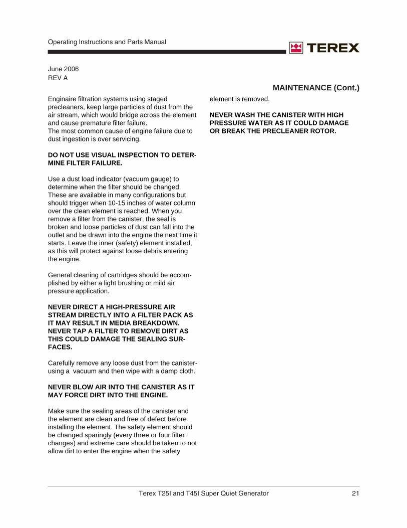
MAINTENANCE (Cont.)Enginaire filtration systems using stagedprecleaners, keep large particles of dust from theair stream, which would bridge across the elementand cause premature filter failure.The most common cause of engine failure due todust ingestion is over servicing.
DO NOT USE VISUAL INSPECTION TO DETER-MINE FILTER FAILURE.
Use a dust load indicator (vacuum gauge) todetermine when the filter should be changed.These are available in many configurations butshould trigger when 10-15 inches of water columnover the clean element is reached. When youremove a filter from the canister, the seal isbroken and loose particles of dust can fall into theoutlet and be drawn into the engine the next time itstarts. Leave the inner (safety) element installed,as this will protect against loose debris enteringthe engine.
General cleaning of cartridges should be accom-plished by either a light brushing or mild airpressure application.
NEVER DIRECT A HIGH-PRESSURE AIRSTREAM DIRECTLY INTO A FILTER PACK ASIT MAY RESULT IN MEDIA BREAKDOWN.NEVER TAP A FILTER TO REMOVE DIRT ASTHIS COULD DAMAGE THE SEALING SUR-FACES.
Carefully remove any loose dust from the canister-using a vacuum and then wipe with a damp cloth.
NEVER BLOW AIR INTO THE CANISTER AS ITMAY FORCE DIRT INTO THE ENGINE.
Make sure the sealing areas of the canister andthe element are clean and free of defect beforeinstalling the element. The safety element shouldbe changed sparingly (every three or four filterchanges) and extreme care should be taken to notallow dirt to enter the engine when the safety
element is removed.
NEVER WASH THE CANISTER WITH HIGHPRESSURE WATER AS IT COULD DAMAGEOR BREAK THE PRECLEANER ROTOR.

Operating Instructions and Parts Manual
22 Terex T25I and T45I Super Quiet Generator
June 2006REV A
TROUBLESHOOTING GUIDE
The engine/generator set is tested and set at the factory for proper operation in the field. These unitsshould never require additional adjustments in the field. If needed, adjustments should only be made by aqualified service technician, otherwise the manufacturer’s warranty may become void.
FAULT POSSIBLE CAUSE SOLUTION
No generator output voltage Circuit breaker tripped Reset circuit breaker
Voltage regulator Check voltage regulator wiring
Defective voltage regulator Replace voltage regulator
Defective Selector Switch By pass by hardwiring generator
Defective generator Refer to generator manual Low generator output voltage Voltage adjustment Adjust voltage potentiometer
set too low
Defective potentiometer By pass or replace
Low engine speed Call TEREX Service
Loose wire on voltage Check wiringselector switch
Fluctuating or surging Check engine fuel, oil,engine speed and air filters
Loose wire on voltage Check wiringregulator sensing circuit
Defective voltage regulator Replace voltage regulator
High generator Voltage adjustment Adjust potentiometeroutput voltage potentiometer
High engine speed Call TEREX Service

Terex T25I and T45I Super Quiet Generator 23
Operating Instructions and Parts Manual
June 2006REV A
FAULT POSSIBLE CAUSE SOLUTION
High generator Defective automatic Replace voltageoutput voltage voltage regulator regulator
Loose wire on voltage Check wiringadjustment potentiometer
Fluctuating generator An “ON/OFF” type Redistribute load ifoutput voltage load may be the cause possible
Fluctuating or surging Check engine fuel, oil,engine speed and air filters
Loose wiring in generator Check connections
Automatic voltage regulator Call TEREX Servicestability setting may bewrong
Loose wire on the automatic Check wiringvoltage regulator sensing lead
Low engine speed Engine speed adjustment Call TEREX Servicehas slipped
Clogged fuel system Check for air leaks, clogged fuelfilter, kinked fuel line, orclogged fuel pick-up tube
Blocked air intake Check air filter
Blocked exhaust system Check engine exhaustsystem, removeobstructions
Contaminated fuel Check fuel/water separator andfuel tank for contamination.Replace fuel if needed
Defective governor on engine Call TEREX Service
TROUBLESHOOTING (Cont.)

Operating Instructions and Parts Manual
24 Terex T25I and T45I Super Quiet Generator
June 2006REV A
TROUBLESHOOTING (Cont.)
FAULT POSSIBLE CAUSE SOLUTION
Low Speed Defective injectors on engine Have injectors checked by aqualified technician
“Surging” engine speed Check engine fuel, oil,and air filters
Engine turns over (cranks), Unit out of fuel Check fuel level in tank, fill asbut won’t run needed
Loose or broken wire in Check wiring to verify 12V DCcontrol circuit fuel injection is being supplied to the pumppump solenoid solenoid
Defective solenoid Replace solenoid
Magnetic Pick-up Adjust for 2.5-3.0 VAC
Clogged fuel system Check fuel system
Air in fuel system “Bleed” fuel system
Defective fuel pump Check and replace if defective
Clogged air intake Check air cleaner
Clogged exhaust Check exhaust system
Contaminated fuel Check fuel/water separator and tank for contamination
Defective injectors Have injection system checkedby a trained technician
Lost engine compression Have compression checked bya trained technician
Engine won’t crank Loose battery cable Check cables and batteryor discharged battery electrolyte level. Recharge
as necessary

Terex T25I and T45I Super Quiet Generator 25
Operating Instructions and Parts Manual
June 2006REV A
TROUBLESHOOTING (Cont.)
FAULT POSSIBLE CAUSE SOLUTION
Engine won’t crank Engine “ON/OFF” switch Check switch position
set in “OFF” position
Blown fuse in DC Replace with 25 Amp. control circuit SLO-BLO TYPE
fuse if needed.
E-Stop Check to see if engaged
Defective starter Replace solenoidsolenoid
Defective starter Replace starter
Oil Pressure or Hi temp Check or call TEREX Serviceswitch defective
Seized engine Have engine checked by aqualified technician
Engine runs, but loses Unit is overloaded Reduce loadspeed
Improper connection Check or Call TEREX Service
Engine runs, but loses Clogged fuel system Check fuel systempower under load air in fuel lines
Blocked air intake Check air cleaner
Blocked exhaust Check exhaust system
Contaminated fuel Check fuel/water separator andfuel tank for contamination
Faulty governor, defective Have unit checked by ainjectors, or defective fuel trained service technicianpump for all of these items
Engine shuts down Oil Pressure Switch Not openingautomatically andTROUBLE LIGHT on Improper coolant Use a 50/50 onCONTROL PANEL or water mixture mix of water andis illuminated anti-freeze only

Operating Instructions and Parts Manual
26 Terex T25I and T45I Super Quiet Generator
June 2006REV A
IF YOU FEEL AN ELECTRIC SHOCK AT ANY TIME WHILE OPERATING THIS UNIT, SHUT IT DOWNIMMEDIATELY! HAVE THE UNIT INSPECTED BY A TRAINED ELECTRICIAN.
THIS ENGINE/GENERATOR SET IS FACTORY INSTALLED, TESTED, AND SET FOR FIELDOPERATION. ANY DAMAGE TO THE ENGINE OR GENERATOR UNITS OCCURRING AFTERADJUSTMENTS ARE MADE IN THE FIELD BY UNAUTHORIZED PERSONNEL WILL NOT BECOVERED BY YOUR MANUFACTURER’S WARRANTY AND WILL ALSO VOID THEMANUFACTURER’S WARRANTY ON THIS PARTICULAR UNIT. IF YOU CAN NOT REACH YOURLOCAL DEALER, CONTACT THE FACTORY SERVICE MANAGER TOLL FREE AT 1-800-433-3026.
FAULT POSSIBLE CAUSE SOLUTION
Engine shuts down Overloaded engine Reduce loadautomatically andTROUBLE LIGHT on Broken fan belt Inspect fan belt and replace asCONTROL PANEL neededis illuminated
Defective thermostat or Inspect thermostatthermocouple switch switch
Defective water pump Inspect water pump and replaceif needed
Blocked cooling air inlet Inspect and remove anyor exhaust obstructions
Defective or grounded Inspect switch and repair ortemperature switch replace
Defective injectors or Have the engine inspected by ainjector pump trained service technician
Low crankcase oil level Check oil level and refill asrequired
Defective oil pump Have the engine inspected bya trained service technician
Defective or grounded oil Inspect switch and repair orpressure switch replace
TROUBLESHOOTING (Cont.)

Terex T25I and T45I Super Quiet Generator 27
Operating Instructions and Parts Manual
June 2006REV A
ELECTRICALTROUBLESHOOTING
5 COMPONENTS THAT CAUSEVOLTAGE RELATED PROBLEMS
POTENTIOMETER
Connects to voltage regulator. Bypass potentiom-eter by unplugging from voltage regulator andinstalling jumper on 2 male spades on regulator.
VOLTAGE REGULATOR
(Located inside the upper control panel behind thegauges.)
Measure DC voltage at F1 & F2. Normal voltage is10 to 12 V DC. Remove 2 wires marked (F1,X)(F2, X X) from voltage regulator. Connect wiremarked F1 to positive and F2 to negative of a 12volt battery. Start unit and measure voltage. If unitproduces close to maximum output, replaceAutomatic Voltage Regulator.
VOLTAGE SELECTOR SWITCH
The correct way to test is to disconnect fromgenerator and hard wire the generator into oneconfiguration. This will eliminate the switch fromthe circuit and verify that the generator is function-ing properly. All contacts should be checkedfollowing the proper schematic with the switchdisconnected from the generator set. Actual loadscan cause failures in contacts that cannot beduplicated using a meter.
OVERCURRENT RELAY
This device causes the 3-phase breaker to tripthat supplies AC power to the distribution lugs ifuneven or excessive current is measured at thedistribution lugs. It is also connected to the 3-phase door switch and will automatically trip the 3-phase breaker when the door is open and pre-vents the breaker from being reset while it is open.
GENERATOR
Test resistance of field, stator and exciter wind-ings. Contact TEREX for procedures or repairfacility recommended by generator manufacturer.
PROCEDURE FOR TESTINGGENERATOR WITH NO OUTPUT
THIS EQUIPMENT USES HIGH VOLTAGECIRCUITS CAPABLE OF CAUSING SERIOUSINJURY OR DEATH! EXCERCISE EXTREMECAUTION AROUND ANY ELECTRICALCOMPONENT WHEN OPERATING THIS UNIT.
IT IS ESSENTIAL THAT ALL TEST INSTRU-MENTS ARE REGULARLY CHECKED FORSAFETY, AND ANY CONNECTION LEADS,PROBES, OR CLIPS, ARE CHECKED TOENSURE THAT THEY ARE SUITABLE FORTHE VOLTAGE LEVELS BEING TESTED.
NEVER ATTEMPT TO TEST A "LIVE" GENERA-TOR UNLESS THERE IS ANOTHER COMPE-TENT PERSON PRESENT WHO CAN SWITCHOFF THE POWER SUPPLY OR SHUT DOWNTHE ENGINE IN AN EMERGENCY.
NEVER EXPOSE "LIVE" CONNECTIONS UN-LESS YOU HAVE CREATED A SAFE WORKINGAREA AROUND YOU. MAKE SURE YOU HAVEMADE ALL OTHER PERSONS IN THE IMMEDI-ATE AREA FULLY AWARE OF WHAT YOUARE DOING.
• When a new generator is not producing voltage,the testing or wiring personnel should first verifythat the unit is wired correctly! The stack switchand generator leads should all be checked aswell as the breaker and sensing leads. If theunit was not wired correctly and you flashed thegenerator, you could burn up the unit. (Do notforget to check the sensing leads!).

Operating Instructions and Parts Manual
28 Terex T25I and T45I Super Quiet Generator
June 2006REV A
• After performing the initial checks above,remove the field wires from the voltageregulator (F1 or X is positive and F2 or XX isnegative). Connect the battery + to the F1 or Xwire and battery - to the F2 or XX wire. Start theengine and check for the rated voltage.Hooking this up incorrectly will reversepolarity and could damage the voltageregulator and /or generator end. This checkshould correct any voltage problems. If yourvoltage does not come up to the rated voltage,this indicates an internal problem with thegenerator end. The output should be close toproper voltage. Also, if the unit comes up tovoltage, check for even reading across the linesif they are not this would mean you probablyhave a problem with the wiring of the switch orgenerator. If the generator voltage readscorrectly you know there is not a problem withthe generator end. Your problem is more thanlikely with the voltage regulator. In this case,you should contact the TEREX servicedepartment.
• If the voltage is uneven between the legs whenyou apply 12 volts to the field wires you need torecheck your wiring connections. (If you cannot find the problem hard wire thegenerator!) After you have the field wireconnected start the unit again and check youroutput voltage. It may still be necessary to flashthe fields to restore residual voltage. This needsto be done with the unit off and the field wiresremoved. (Do not flash the regulator, flashthe field wires)
• As with any electrical device use extremecaution when working around a runninggenerator it could cost you your life. Observeproper polarity when working with the regulatorso you don’t break something that is not brokento begin with, and if you are ever in doubt, ask.
INSTALLATION AND ANY WORK PERFORMEDON THIS UNIT SHOULD BE DONE ONLY BY AQUALIFIED ELECTRICIAN.
PROCEDURE FOR CHANGINGTHE MAGNETIC PICK-UPSENSOR
• Make sure generator is turned off and e-stop isengaged before opening control panel.
• Locate the two wires going to the speedcontroller mounted on the inside of the controlpan marked MPU + and MPU -.
• Both wires are isolated in their own shieldedcable.
• Once the wires are loose, pull them through theback of the control box until they are completelyfree from all ty-wraps and wire harnesses.
• Unscrew and remove the old sensor.
• Align the flywheel tooth to the center of thesensor hole.
• Install new sensor until it bottoms out onflywheel tooth and then back it off ¼ turn.
• To insure proper installation, the sensor must
THIS EQUIPMENT USES HIGH VOLTAGE CIR-CUITS CAPABLE OF CAUSING SERIOUS IN-JURY OR DEATH! EXCERCISE EXTREME CAU-TION AROUND ANY ELECTRICAL COMPO-NENT WHEN OPERATING THIS UNIT.
INSTALLATION AND ANY WORK PERFORMEDON THIS UNIT SHOULD BE DONE ONLY BY AQUALIFIED ELECTRICIAN.
PROCEDURE FOR TESTINGGENERATOR WITH NO OUTPUT(Cont.)
ELECTRICAL TROUBLESHOOTING (Cont.)

Terex T25I and T45I Super Quiet Generator 29
Operating Instructions and Parts Manual
June 2006REV A
ELECTRICAL TROUBLESHOOTING (Cont.)
be checked with a voltage meter. With the enginein a starting sequence check for 2.5 to 3 VACbetween the red and black wire. Adjust thesensor in or out to obtain the correct voltage.
• Once the voltage is correct, reinstall theshielded cable through the control box openingand reattach the wire leads to the speedcontroller. Also, secure the new cable throughthe housing with ty-wraps where needed.
If any further adjustment is needed to the voltageof the generator please call Terex at 1-800-433-3026 for assistance.
PROCEDURE FOR CHANGINGTHE MAGNETIC PICK-UPSENSOR (Cont.)
PROCEDURE FOR CHANGINGTHE VOLTAGE POTENTIOMETER
THIS EQUIPMENT USES HIGH VOLTAGECIRCUITS CAPABLE OF CAUSING SERIOUSINJURY OR DEATH! EXCERCISE EXTREMECAUTION AROUND ANY ELECTRICALCOMPONENT WHEN OPERATING THIS UNIT.
INSTALLATION AND ANY WORK PERFORMEDON THIS UNIT SHOULD BE DONE ONLY BY AQUALIFIED ELECTRICIAN.
• Make sure generator is turned off and e-stop isengaged before opening control panel.
• Locate the two wires going to the back of thepotentiometer. Both wires will be white with ared stripe.
• Both wires have been spliced into harnesswires and should be cut so that the splice istaken out. It is better to have as few splices aspossible and you will be replacing the spliceyou cut out.
• Once the wires are loose, go to the front of thecontrol panel and loosen the lock nut holdingthe potentiometer.
• Put the new potentiometer in its place andretighten lock nut.
• Reattach new wires to the same wires and inthe same configuration as the ones that werecut loose in step 3.
• After completing the installation of the newpotentiometer go back and check allconnections to make sure everything is tightand that no connections are loose, this includesall other wiring on the back of the control paneland on the inside of the control box.
• You should now be able to restart the generatorand check for proper operation.
If any further adjustment is needed to the voltageof the generator please call TEREX at 1-800-433-3026 for assistance.

Operating Instructions and Parts Manual
30 Terex T25I and T45I Super Quiet Generator
June 2006REV A
Control Panel Wiringfor Cascade w/Electronic GovernorDrawing #ES1000000(Optional)
Terex T25I and T45I Super Quiet Generator 31
Operating Instructions and Parts Manual
June 2006REV A
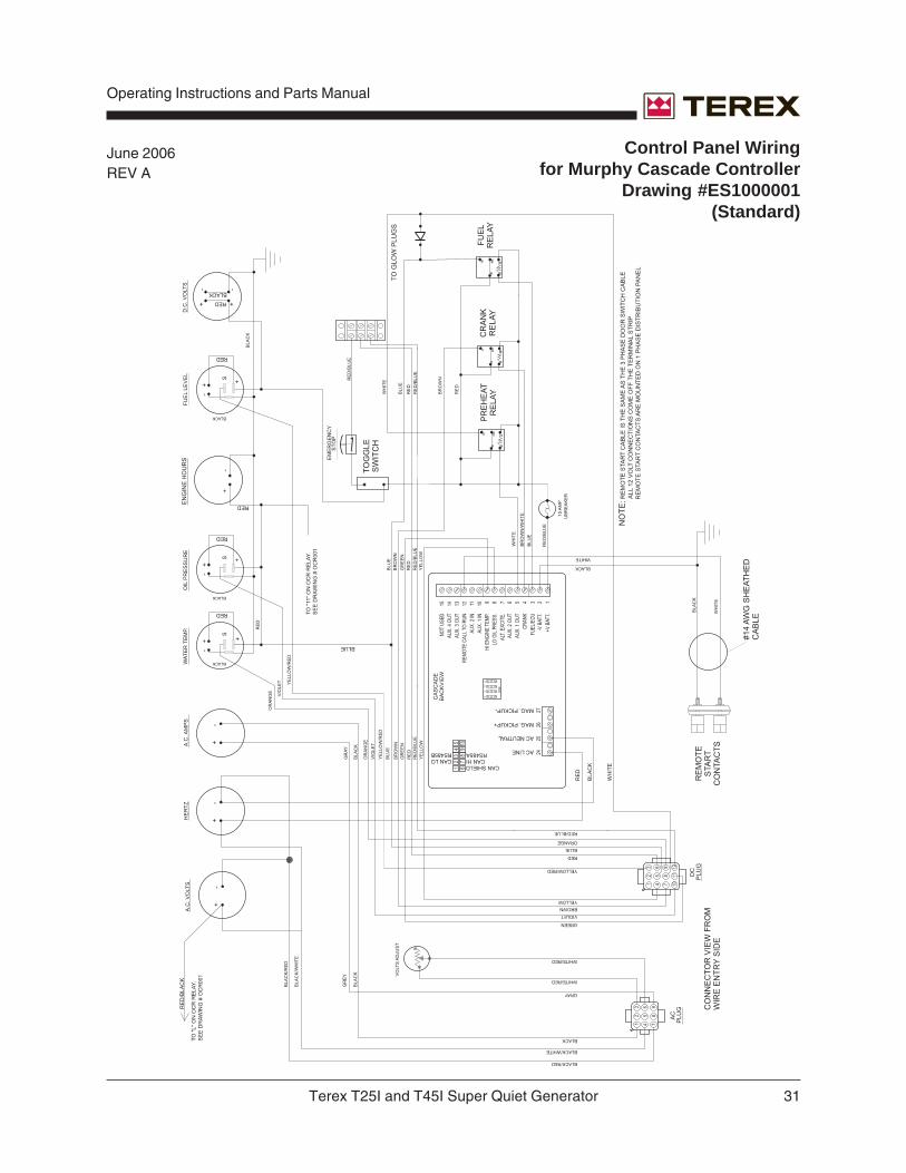
Control Panel Wiringfor Murphy Cascade Controller
Drawing #ES1000001(Standard)

Operating Instructions and Parts Manual
32 Terex T25I and T45I Super Quiet Generator
June 2006REV A
Distribution Panel Wiringfor "C" Series Single PhaseControlDrawing #ES1000003

Terex T25I and T45I Super Quiet Generator 33
Operating Instructions and Parts Manual
June 2006REV A Three Position Stack Switch Wiring
Drawing #ES1000005

Operating Instructions and Parts Manual
34 Terex T25I and T45I Super Quiet Generator
June 2006REV AOvercurrent Relay Wiring
Drawing #ES1000006
Terex T25I and T45I Super Quiet Generator 35
Operating Instructions and Parts Manual
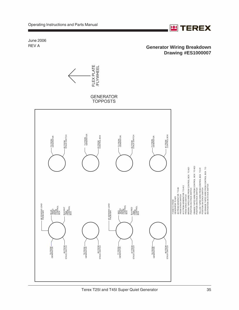
June 2006REV A Generator Wiring Breakdown
Drawing #ES1000007

Operating Instructions and Parts Manual
36 Terex T25I and T45I Super Quiet Generator
June 2006REV A
Standard Generator Wiringfor "C" SeriesDrawing #ES1000008

Terex T25I and T45I Super Quiet Generator 37
Operating Instructions and Parts Manual
June 2006REV A
T25I / T45I SPECIFICATIONS ANDDIMENSIONS
MODEL T25I T45I
POWER CAPABILITY-PRIMEkVA (kilovolt-amps) 25 45kW 20 363 Phase Amp Ratings
208V 69 125240V 60 108480V 30 54
POWER CAPABILITY-STANDBYkVA (kilovolt-amps) 30 50kW (kilowatts) 24 403 Phase Amp Ratings 208V 83 139
240V 72 120480V 36 60
VOLTAGE3 Phase 208, 220, 240, 416, 440, 480 Standard Standard600 Volt Optional Optional
1 Phase 120, 127, 139, 240, 254, 277 Standard Standard
Max Motor Starting1 Hp 12 27kW 9 20
SKVA 70 165
DIESEL ENGINEManufacturer Isuzu IsuzuModel 4LE1PV02 4JG1TPVCylinder 4 4Air Intake (aspiration) Natural TurboCooling System Std Rad Std RadFuel Capacity (gal) 64 64Run Time (75% load) 53 29Fuel Consumption, Prime Power (gal per hr) 100% load 1.5 2.8
75% load 1.1 2.250% load 0.8 1.725% load 0.4 1.2
dBA 64 64Controller Type Analog/Digital Analog/DigitalStart/Stop Controller Cascade Cascade12V Battery (CCA) 750 750
Operating Instructions and Parts Manual
38 Terex T25I and T45I Super Quiet Generator
June 2006REV A
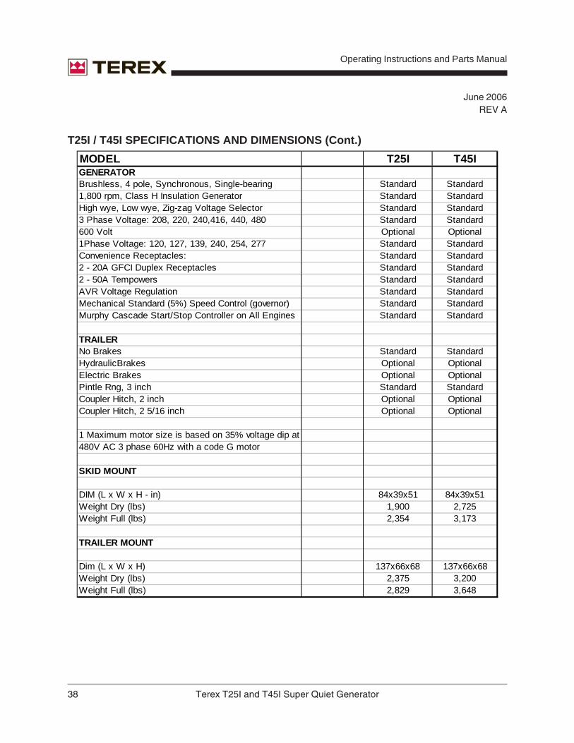
T25I / T45I SPECIFICATIONS AND DIMENSIONS (Cont.)
MODEL T25I T45IGENERATORBrushless, 4 pole, Synchronous, Single-bearing Standard Standard1,800 rpm, Class H Insulation Generator Standard StandardHigh wye, Low wye, Zig-zag Voltage Selector Standard Standard3 Phase Voltage: 208, 220, 240,416, 440, 480 Standard Standard600 Volt Optional Optional1Phase Voltage: 120, 127, 139, 240, 254, 277 Standard StandardConvenience Receptacles: Standard Standard2 - 20A GFCI Duplex Receptacles Standard Standard2 - 50A Tempowers Standard StandardAVR Voltage Regulation Standard StandardMechanical Standard (5%) Speed Control (governor) Standard StandardMurphy Cascade Start/Stop Controller on All Engines Standard Standard
TRAILERNo Brakes Standard StandardHydraulicBrakes Optional OptionalElectric Brakes Optional OptionalPintle Rng, 3 inch Standard StandardCoupler Hitch, 2 inch Optional OptionalCoupler Hitch, 2 5/16 inch Optional Optional
1 Maximum motor size is based on 35% voltage dip at480V AC 3 phase 60Hz with a code G motor
SKID MOUNT
DIM (L x W x H - in) 84x39x51 84x39x51Weight Dry (lbs) 1,900 2,725Weight Full (lbs) 2,354 3,173
TRAILER MOUNT
Dim (L x W x H) 137x66x68 137x66x68Weight Dry (lbs) 2,375 3,200Weight Full (lbs) 2,829 3,648

Terex T25I and T45I Super Quiet Generator 39
Operating Instructions and Parts Manual
November 2007REV B
FASTENER STAINLESS STAINLESS SAE GRADE SAE GRADE SAE GRADE SAE GRADESIZE STEEL* STEEL* 5 PLATED 5 PLATED 8 PLATED 8 PLATEDUNF NYLOK (METRIC NYLOK (METRIC NYLOK
& NUT 8.8) NUT 10.9) NUTUNC#6 (10-12) (8.5-10) (14-16)#8 (20-22) (17-19) (25-28)#10 (26-32) (22-27) (40-45)1/4" (75-94) (64-80) 7-9 12-14
5/16" 12-Nov 14-Dec 15-17 23-263/8" 20-22 22-24 28-34 45-50
7/16" 31-33 32-35 40-45 70-751/2" 43-45 45-50 75-85 70-80 100-110 95-105
9/16" 57-63 60-65 80-100 75-95 145-160 135-1505/8" 92-104 100-105 130-170 125-165 175-205 165-1953/4" 128-135 140-150 220-240 205-225 380-420 365-4054mm (22-26) (19-22) (23-27)6mm (45-50) (38-43) (72-78)8mm 12-Nov 9-10 14-16
10mm 18-20 15-17 45-50 40-45 70-7512mm 42-44 36-38 56-60 50-55 95-10516mm 140-14818mm 185-20020mm 280-290
TORQUE SPECIFICATIONS
Generator FT*LB
Flex Plate to Flywheel 12-15
Generator Case to Bellhousing 60
1/2" Socket Head Cap Screws for Lifting Channel 126
1/2" Hex Head Screws for Lifting Channel 120
Genset Isolators 33
GENERATOR TORQUE SPECIFICATIONS

Operating Instructions and Parts Manual
40 Terex T25I and T45I Super Quiet Generator
June 2006REV A
This page intentionally left blank.

Terex T25I and T45I Super Quiet Generator 41
Operating Instructions and Parts Manual
Part Number Description Quantity Price
All backordered parts will be shipped when available via the same ship method as the original orderunless noted below:
o Ship complete order only - no backorders
o Ship all available parts and contact customer on disposition of backordered parts
o Other (please specify)
Please fill out completely
Date _________________________________ Account Number _______________________________
Your Name ______________________________ Your Fax Number _____________________________
_________________________________ Your Phone Number ____________________________
Bill To _________________________________ Ship To ___________________________________
_________________________________ ___________________________________
_________________________________ ___________________________________
_________________________________ ___________________________________
Purchase Order Number ____________________ Ship Via ___________________________________
Model(s) ______________________________________________________ Serial No.(s) _________________
Optional Equipment __________________________________________________________________________
FOR TEREX USE ONLY
Order Number ______________ Origin Code ________________ Comments _________________________
Date Scheduled ____________ Ship Condition ______________ __________________________________
Order Total ________________ Terms Code ________________ __________________________________
rem
ove
this
pag
e an
d m
ake
copi
esre
mov
e th
is p
age
and
mak
e co
pies
SERVICE PARTS FAX ORDER FORMFAX TO: (800) 633-5534 OR TOLL FREE: 800-433-3026

Operating Instructions and Parts Manual
42 Terex T25I and T45I Super Quiet Generator
June 2006REV A
This page intentionally left blank.

Terex T25I and T45I Super Quiet Generator 43
Operating Instructions and Parts Manual
June 2006REV A
PARTS CATALOG
SECTION
PARTS CATALOG
Operating Instructions and Parts Manual
44 Terex T25I and T45I Super Quiet Generator
June 2006REV A
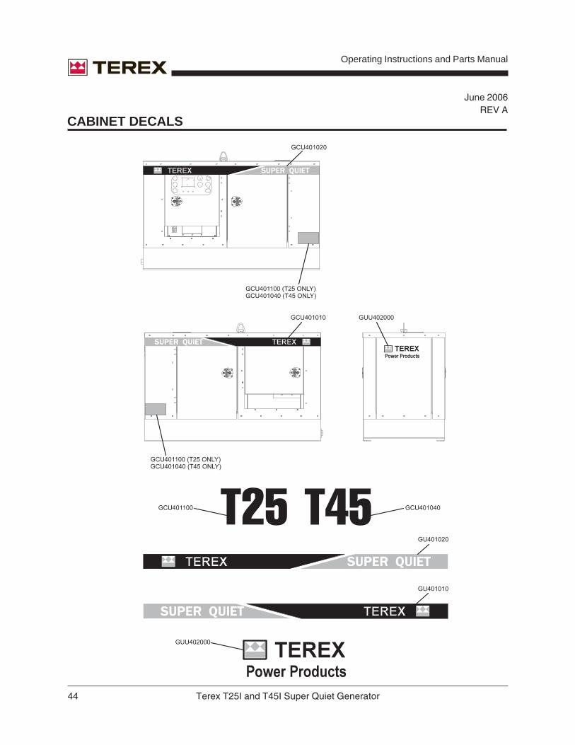
CABINET DECALS

Terex T25I and T45I Super Quiet Generator 45
Operating Instructions and Parts Manual
June 2006REV A
SAFETY DECALS

Operating Instructions and Parts Manual
46 Terex T25I and T45I Super Quiet Generator
June 2006REV A
FIGURE 1 - BASE W/FUEL TANK
Terex T25I and T45I Super Quiet Generator 47
Operating Instructions and Parts Manual
June 2006REV A
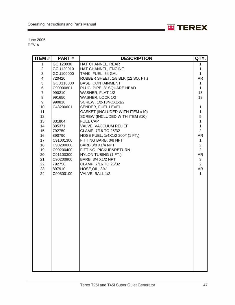
ITEM # PART # DESCRIPTION QTY.1 GCI120030 HAT CHANNEL, REAR 12 GCU120010 HAT CHANNEL, ENGINE 13 GCU100000 TANK, FUEL, 64 GAL 14 720420 RUBBER SHEET, 1/8 BLK (12 SQ. FT.) AR5 GCU110000 BASE, CONTAINMENT 16 C90900601 PLUG, PIPE, 3" SQUARE HEAD 17 990210 WASHER, FLAT 1/2 188 991650 WASHER, LOCK 1/2 189 990810 SCREW, 1/2-13NCX1-1/210 C43200601 SENDER, FUEL LEVEL 111 GASKET (INCLUDED WITH ITEM #10) 112 SCREW (INCLUDED WITH ITEM #10) 513 831804 FUEL CAP 114 895371 VALVE, VACCUUM RELIEF 115 792750 CLAMP 7/16 TO 25/32 216 890790 HOSE FUEL, 1/4X1/2 200# (1 FT.) AR17 C91001300 FITTING BARB, 3/8 NPT 118 C90200600 BARB 3/8 X1/4 NPT 219 C90200400 FITTING, PICKUP&RETURN 220 C91100300 NYLON TUBING (1 FT.) AR21 C90200900 BARB, 3/4 X1/2 NPT 322 792750 CLAMP, 7/16 TO 25/32 223 897910 HOSE,OIL, 3/4" AR24 C90800100 VALVE, BALL 1/2 1
Operating Instructions and Parts Manual
48 Terex T25I and T45I Super Quiet Generator
June 2006REV A
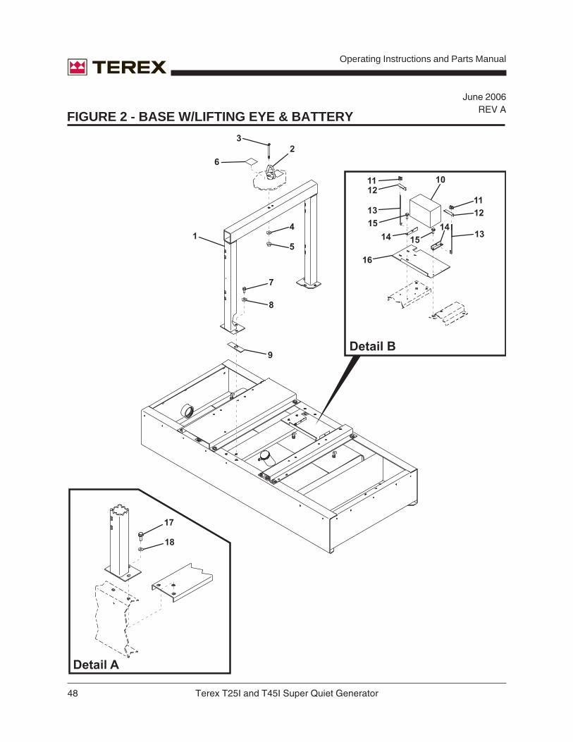
FIGURE 2 - BASE W/LIFTING EYE & BATTERY

Terex T25I and T45I Super Quiet Generator 49
Operating Instructions and Parts Manual
June 2006REV A
ITEM# PART# DESCRIPTION QTY.1 GCU500000 LIFTING ASSEMBLY 12 C82301010 LIFTING EYE 5000 LBS 13 C82300850 BOLT, 1/2 -20 X 6 SOCKETHEAD CAP 24 990210 WASHER FLAT 1/2 5 990200 NUT, LOCK NYLON INSERT 1/2-13NC 46 CY59A111 PLASTIC 1/8 X 3 X 4 27 994600 SCREW 1/2-13NC X 1-1/2 68 990210 WASHER FLAT 1/2 189 GCU500042 LIFTING CHAN SPACER 110 261252 BATTERY, WET 12V GRP34/750CCA 111 NUT, WING 212 CU22A252 ANGLE BATTERY 113 C33700800 HOOK BATTERY HOLD DN 114 GCU121010 BATTERY TIE DOWN 215 995810 SCREW 1/4-20NC X 5/8 HWH 416 GCU121000 TRAY BATTERY 117 994600 SCREW 1/2-13NC X 1-1/2 618 991650 WASHER LOCK 1/2 18

Operating Instructions and Parts Manual
50 Terex T25I and T45I Super Quiet Generator
June 2006REV A
FIGURE 3 - GENSET

Terex T25I and T45I Super Quiet Generator 51
Operating Instructions and Parts Manual
November 2007REV B
ITEM # PART # DESCRIPTION QTY.1 630975 GENERATOR, NEWAGE, 20KW-T25I 12 630944 GENERATOR, NEWAGE, 40KW-T45I 13 C33602400 MOUNT, VIBRATION FAIL 44 981635 SCREW, 1/2-13NCX1 125 CC32T010 HAT CHANNEL, NEWAGE, T25I 15 GCI120051 HAT CHANNEL, NEWAGE, T45I 16 981660 SCREW, 1/2-13NCX1-1/2 47 990210 WASHER, FLAT 1/2 188 990200 NUT, LOCK-NYLON INSERT 49 51601460 SCREW, FLANGE 3/8-16 X 1 210 732112PP ENGINE, ISUZU, 20KW, 4LE1PV02,POWER PAK-508-T25I 111 732114PP ENGINE, ISUZU,30-40KW 4JG1TPV,POWER PACK-503-T45I 112 836427 RECTIFIER SERVICE KIT 113 830001 BCI GENERATOR OPERATION MANUAL 1

Operating Instructions and Parts Manual
52 Terex T25I and T45I Super Quiet Generator
June 2006REV A
FIGURE 4 - CABINET ASSEMBLY

Terex T25I and T45I Super Quiet Generator 53
Operating Instructions and Parts Manual
June 2006REV A
ITEM # PART # DESCRIPTION QTY.1 GCU460000 HOUSING, TOP PANEL 12 GCU470001 HOUSING, JAMB DOOR 23 GCU420021 HOUSING, FRONT STREET 14 GCU420011 HOUSING, FRONT CURB 15 GCU470001 HOUSING, JAMB DOOR 26 GCU420041 HOUSING, DISTRIBUTION PANEL 17 GCU420031 HOUSING, CONTROL PANEL 18 GCU480000 HOUSING, REAR LOUVER 19 GCU480010 GUARD, LOUVER MESH 110 GCU480100 BAFFLE, LOUVER 111 GCI491001 BULKHEAD, T-25I 111 GCI490001 BULKHEAD, T-45I 112 GUU401100 SEAL, TRIMLOCK 7/16 AR13 GCU110060 MUFFLER, FRONT MOUNT 114 C54200601 SCREW, FLANGE 5/16 -18 815 720440 WEATHERSTRIP ADHESIVE AR16 669174 PLATE DECK SCREW-OUT,THREADED RING 117 669174 PLATE DECK SCREW-OUT 118 990670 RIVET POP 3/16 X 1/2 619 C54400200 SCREW, TEK #10 X 3/4 420 994490 WASHER, FLAT SNUBBING 1221 993422 SCREW, FLANGE 1/4-20 X .75, SS 6422 990150 NUT, LOCK NYLON, 1/4-20, GR2 4023 C71014 WASHER, FLAT. 11/16" O.D. 8424 C33200500 FILTER, FUEL, WATER SEPARATOR, COMPLETE 125 CR25-P WATER SEPARATOR ELEMENT ONLY 1

Operating Instructions and Parts Manual
54 Terex T25I and T45I Super Quiet Generator
June 2006REV A
FIGURE 5 - CABINET ASSEMBLY W/DOORS

Terex T25I and T45I Super Quiet Generator 55
Operating Instructions and Parts Manual
June 2006REV A
ITEM # PART # DESCRIPTION QTY.1 GCU430000 HOUSING, DISTRIBUTION DOOR 12 GCU430020 HOUSING, ACCESS DOOR 13 C71100500 FOAM BLACK URETHANE AR4 794891 HINGE, LIFT-OFF STEEL 45 C21353 BOLT, CARRIAGE 3/8-16X3/4 Z KEG 326 C73000100 TRIM LOCK 1/4 AR7 GCU450000 HOUSING, FRONT PANEL 18 993422 SCREW, FLANGE 1/4-20X.75 59 C72100400 WEATHER STRIP 3/8X3/4 AR10 GCU430030 HOUSING, ACCESS DOOR 111 C53200100 LITERATURE BOX 112 C51101000 LATCH 413 992040 RIVET, POP 3/16X.602 1014 CU54T021 WINDOW, CONTROL DOOR 115 C74100100 GASKET, WINDOW CONTROL DR AR16 GCU480000 HOUSING, REAR LOUVER 117 C71100200 FOAM, BLACK URETHANE 1/2 AR18 680465 EDGE STRIP , SBM RUBBER AR19 GUU401100 TRIMLOCK SEAL 7/16 AR20 993422 SCREW, FLANGE 1/4-20X.75 6421 990170 NUT, LOCK NYLON INSERT,3/8-16NC GR 2 ZPN BIN 3222 981070 WASHER, FLAT 5/16 3223 C71014 WASHER, FLAT,11/16" OD 3224 GCU430010 HOUSING, CONTROL DOOR 125 41135000 POP RIVET 226 51400200 BUMPER 2

Operating Instructions and Parts Manual
56 Terex T25I and T45I Super Quiet Generator
June 2006REV A
FIGURE 6 - CONTROL PANEL ASSEMBLY- UPPER

Terex T25I and T45I Super Quiet Generator 57
Operating Instructions and Parts Manual
June 2006REV A
ITEM # PART # DESCRIPTION QTY.1 GCU320000 CONTROL PAN ASSY 12 GCU300002 CONTROL PANEL 13 C42200500 POTENTIOMETER. VOLTAGE 14 682070 BREAKER, MINI 1P 15A 15 C42208400 SWITCH, TOGGLE SINGLE 16 C43100800 GAUGE, DC VOLT 17 C43200400 GAUGE, OIL PRESSURE 18 260360 HOURMETER, 12V DC 19 C43200300 GAUGE, WATER TEMP 12V 110 C43200600 GAUGE, FUEL W/BLACK 111 261341 CASCADE CONTROLLER 112 INCLUDED WITH ITEM 11 413 C43100600 METER, VOLT DUAL 114 C43100400 METER, FREQUENCY 115 C43100500 METER, AMP 0-100 W/ 116 R980195 SCREW, 1/4-20NCX3/4 217 990340 WASHER, FLAT 1/4 818 992040 RIVET, POP 3/16X.602 1019 CB45A112 HARNESS, AC CTRL/PNL 120 CU45A100 HARNESS, CTRL UNIVERSAL 121 C51600800 NUT, CLIP 1/4 -20X3/4 422 GCU320100 PLASTIC, ABS 1/8 X 10.5 X 22.5 123 C51200201 HINGE, PIANO 9 SS 224 C42401700 RELAY, OVER CURRENT 125 686735 RAIL, RELAY MOUNTING AR26 SA465 OR SX460 AVR - CHECK UNIT BEFORE ORDERING PART 127 C42404000 TERMINAL STRIP, 6 POS 128 R660115 JUMPER, TERMINAL STRIP 229 CDWV40150 RELAY, 50A BOSCH 330 CDWV40151 RELAY, BASE 50A BOSCH 331 CDWV40152 RELAY, PIN 1232 853813 DECAL, KIT RECEPTACLES AND BREAKERS 133 853838 DECAL, KIT CONTROL PANEL CASCADE 1

Operating Instructions and Parts Manual
58 Terex T25I and T45I Super Quiet Generator
June 2006REV A
FIGURE 7 - CONTROL PANEL ASSEMBLY - LOWER

Terex T25I and T45I Super Quiet Generator 59
Operating Instructions and Parts Manual
June 2006REV A
ITEM # PART # DESCRIPTION QTY.1 GCU320000 CONTROL PANEL ASSEMBLY 12 GCU300000 PANEL, 1PHASE 13 C42104500 BREAKER,70A SHUNTTRIP, T25I 13 C42104800 BREAKER,150A,SHUNTTRIP, T45I 14 685880 BREAKER, 2POLE 1PH 45A, T25I 14 685930 BREAKER, 2POLE 1PH 90A, T45I 15 C42103400 BREAKER, 20A 120/240V 26 C42103600 BREAKER, 50A 120/240V 27 684640 RECEPTACLE, 20A 120V 28 C42500100 TRANSFORMER, 100:5 39 C42500100 TRANSFORMER, 100:5, T25I 19 C42500200 TRANSFORMER,200:5, T45I 110 CU41S030 TEMP, POWER SLOPE 111 C47100300 RECEPTACLE, TWISTLOCK, 50A 212 R980195 SCREW, 1/4-20NCX3/4 413 990340 WASHER, FLAT 1/4 814 CU45A010 HARNESS, AC/GEN 115 C51601442 SCREW, FLANGE 1/4 -20 X 3/4 PATCH 416 C51601441 NUT, FLANGE, 1/4"-20 Z 417 990340 WASHER, FLAT 1/4 818 990340 WASHER, FLAT 1/4 819 853752 DECAL, REMOTE START 120 853813 DECAL, KIT RECEPTACLES AND BREAKERS 121 66812 E-STOP PUSHBUTTON 122 686662 E-STOP LABEL PLATE 123 66817 E-STOP CONTACT (N.C.) 124 671278 REMOTE START CONTACT 1

Operating Instructions and Parts Manual
60 Terex T25I and T45I Super Quiet Generator
June 2006REV A
FIGURE 8 - DISTRIBUTION PANEL

Terex T25I and T45I Super Quiet Generator 61
Operating Instructions and Parts Manual
June 2006REV A
ITEM # PART # DESCRIPTION QTY.1 GCU310000 PANEL DISTRIBUTION 12 CC43A043 DISTRIBUTION, LUG PANEL 13 C37816 TURNBUCKLE 1/4-20 X 1 3/4 44 GCU310009 5 LUG REAR COVER 15 C51601443 SCREW, FLANGE 1/4 -20 46 990340 WASHER, FLAT 1/4 47 C51601442 SCREW, FLANGE 1/4 -20 48 990340 WASHER, FLAT 1/4 89 C42200702 PLUNGER (ACTUATOR) 110 C42200701 SWITCH, SNAP-ACTION, USE WITH 42200702 111 SCREWS, INCLUDED WITH ITEM 9 212 SCREWS, INCLUDED WITH ITEM 9 213 U51A400 DECAL, L1, L2, L3, N 114 INCLUDED WITH ITEM 13 115 INCLUDED WITH ITEM 13 116 INCLUDED WITH ITEM 13 117 851820 DECAL, SYMBOL FOR GROUND 118 C74954 SCREW, HEX 1/2 -13 X,2.5 SBZ 519 995970 WASHER, LOCK STAR 1/2 520 C74972 WASHER, FLAT 1/2 SBZ 521 C75240 LOCK, WASHER 1/2 SBZ 1022 C74967 NUT, HEX 1/2-13 SBZ 1023 852255 DECAL, 3PH DISTRIBUTION PANEL, ALL 5 LUG 3PH UNITS 124 990400 WASHER, LOCK 1/4 825 990340 WASHER, FLAT 1/4 8

Operating Instructions and Parts Manual
62 Terex T25I and T45I Super Quiet Generator
June 2006REV A
FIGURE 9 - MUFFLER ASSEMBLY
Terex T25I and T45I Super Quiet Generator 63
Operating Instructions and Parts Manual
November 2007REV B
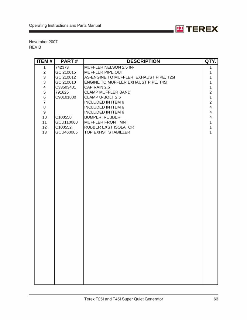
ITEM # PART # DESCRIPTION QTY.1 742373 MUFFLER NELSON 2.5 IN- 12 GCI210015 MUFFLER PIPE OUT 13 GCI210012 AS-ENGINE TO MUFFLER EXHAUST PIPE, T25I 13 GCI210010 ENGINE TO MUFFLER EXHAUST PIPE, T45I 14 C33503401 CAP RAIN 2.5 15 791625 CLAMP MUFFLER BAND 26 C90101000 CLAMP U-BOLT 2.5 17 INCLUDED IN ITEM 6 28 INCLUDED IN ITEM 6 49 INCLUDED IN ITEM 6 410 C100550 BUMPER, RUBBER 411 GCU110060 MUFFLER FRONT MNT 112 C100552 RUBBER EXST ISOLATOR 113 GCU460005 TOP EXHST STABILZER 1

Operating Instructions and Parts Manual
64 Terex T25I and T45I Super Quiet Generator
June 2006REV A
FIGURE 10 - AIR CLEANER ASSEMBLY

Terex T25I and T45I Super Quiet Generator 65
Operating Instructions and Parts Manual
June 2006REV A
ITEM # PART # DESCRIPTION QTY.1 834461 AIR CLEANER ASSEMBLY - T45 12 868139 AIR CLEANER ELEMENT 13 834458 AIR CLEANER ASSEMBLY - T25 14 834460 AIR CLEANER ELEMENT 1

Operating Instructions and Parts Manual
66 Terex T25I and T45I Super Quiet Generator
November 2007REV B
FIGURE 11A - ENGINES - T25I

Terex T25I and T45I Super Quiet Generator 67
Operating Instructions and Parts Manual
November 2007REV B
ITEM # PART # DESCRIPTION QTY.1 868069 INJECTOR NOZZLE ASSEMBLY 12 868068 FUEL INJECTOR PUMP 13 868075 OIL FILTER 14 868142 DIPSTICK 15 868086 ENGINE STOP SOLENOID 16 868070 FUEL FEED PUMP ASSEMBLY 17 868063 GLOW PLUG 18 868065 THERMOSTAT 19 868036 FUEL FILTER 110 868067 FAN BELT 111 868143 WATER PUMP 112 868076 STARTER 113 868077 GENERATOR / ALTERNATOR 114 868023 OIL FILLER CAP 115 868024 OIL DRAIN PLUG 116 868121 VALVE COVER GASKET 117 868078 TIMER 118 868011 TEMPERATURE SENDER 119 868012 FAN 120 868013 FAN GUARD 121 868014 RADIATOR 122 C33200500 FILTER, WATER SEPARATOR 123 116075 TEMPERATURE SWITCH 124 116076 OIL PRESSURE SWITCH 125 116077 OIL PRESSURE SENDER 1

Operating Instructions and Parts Manual
68 Terex T25I and T45I Super Quiet Generator
November 2007REV B
FIGURE 11B - ENGINES - T45I

Terex T25I and T45I Super Quiet Generator 69
Operating Instructions and Parts Manual
November 2007REV B
ITEM # PART # DESCRIPTION QTY.1 868048 INJECTOR NOZZLE ASSEMBLY 12 868033 OIL FILTER 13 868049 DIPSTICK 14 868034 ENGINE STOP SOLENOID 15 868051 FUEL FEED PUMP ASSEMBLY 16 868035 GLOW PLUG 17 868065 THERMOSTAT 18 868036 FUEL FILTER 19 868053 FAN BELT 110 868037 WATER PUMP 111 868039 GENERATOR / ALTERNATOR 112 868023 OIL FILLER CAP 113 868024 OIL DRAIN PLUG 114 868046 VALVE COVER GASKET 115 440346 TEMPERATURE SENDER 116 C33200500 FILTER, WATER SEPARATOR 117 116084 TEMPERATURE SWITCH 118 116086 FAN GUARD 119 116087 FAN 120 116077 OIL PRESSURE SENDER21 116076 OIL PRESSURE SWITCH 1

Operating Instructions and Parts Manual
70 Terex T25I and T45I Super Quiet Generator
November 2007REV B
FIGURE 12 - VOLTAGE SELECTOR SWITCH

Terex T25I and T45I Super Quiet Generator 71
Operating Instructions and Parts Manual
November 2007REV B
ITEM # PART # DESCRIPTION QTY.1 C42201102 VOLTAGE SWITCH, T25I 11 C42202402 VOLTAGE SWITCH, T45I 12 CD42I031 BCI, FRAME EXTENSION, BACK 13 CD42I030 BCI, FRAME EXTENSION, FRONT 14 CD42I040 BCI. FRAME EXTENSION, SIDE 25 CL-008 DECAL, DO NOT CHANGE POSITION 1

Operating Instructions and Parts Manual
72 Terex T25I and T45I Super Quiet Generator
November 2007REV B
FIGURE 13 - TRAILER

Terex T25I and T45I Super Quiet Generator 73
Operating Instructions and Parts Manual
November 2007REV B
OPTION # PART # DESCRIPTION QTY.0GSX0031 841082 CENTER MOUNT JACK 10GSX0164 841083 LED TRAILER LIGHTS 20GSX0030 840223 CORNER JACKS 2
840223 JACK MOUNT TUBE 20GSX0040 840641 TRAILER HITCH, 2" BALL 10GSX0115 C11261 TRAILER HITCH, 2 /16" BALL, 12,000 LB RATED 10GSX0116 261190 TRAILER LIGHT CONNECTOR, 4 POLE FLAT 10GSX0137 841067 SPARE TIRE AND WHEEL, MOUNTS ON A FRAME 1
124317 SPARE TIRE MOUNTING BRACKET 1841070 SPARE TIRE MOUNTING BRACKET,UNIVERSAL 1
0GSX0113 124877 TRAILER, STANDARD, NO BRAKES 10GSX0118 124879 TRAILER, HYDRAULIC BRAKES 10GSX0114 124878 TRAILER, ELECTRIC BRAKES 1
ITEM # PART # DESCRIPTION QTY.1 124877 TRAILER, STANDARD, NO BRAKES 12 834207 AXLE, COMPLETE 13 841061 TIRE AND WHEEL MOUNTED, ST205 24 840396 LUG NUT 125 834208 SAFETY CHAIN 26 834212 HITCH MOUNT 17 C15309 BOLT 68 990210 WASHER 69 993170 NUT 610 834213 BOLT 211 834214 CONNECTOR, 6 PIN 112 834215 NUT 213 834216 RING HITCH, STANDARD 114 834237 JACK 115 834218 PIN 116 840082 FENDER, PLASTIC 217 834221 AMBER CLEARANCE LIGHT 218 834233 RED CLEARANCE LIGHT 219 834209 C-HOOK, SAFETY CHAIN 220 834232 CLEARANCE LIGHT MOUNTING KIT 421 834234 STOP, TAIL LIGHT W/GROMMET AND PLUG 222 834236 TAG LIGHT KIT 1

Operating Instructions and Parts Manual
74 Terex T25I and T45I Super Quiet Generator
November 2007REV B
OPTION # PART # DESCRIPTION QTY.0GSX0086 686711 BATTERY DISCONNECT SWITCH 10GSX0036 261235 TRICKLE CHARGER WITH MALE RECEPTACLE 1
682776 RECEPTACLE, 15A, 125V, 1682777 RECEPTACLE, 15A, 125V, 1
0GSX0037 261236 3.5A BATTERY CHARGER WITH MONITORING 1682776 RECEPTACLE, 15A, 125V, 1682777 RECEPTACLE, 15A, 125V, 1
0GSX0141 C33301001 BLOCK HEATER, ISUZU, T45 1682776 RECEPTACLE, 15A, 125V, 1682777 RECEPTACLE, 15A, 125V, 1
0GSX0143 C33301000 BLOCK HEATER, ISUZU, T25 1682776 RECEPTACLE, 15A, 125V, 1682777 RECEPTACLE, 15A, 125V, 1
0GSX0057 C-SERIES CAM LOCK DISTRIBUTION PANEL WITH 1STANDARD LUG PANEL
0GSX0066 C33204000 EXTERNAL FUEL CONNECTION 10GSX0145 C33203000 ELECTRONIC GOVERNOR, T45 1
C42300600 MAG PICK UP 1742376 ACTUATOR, ELECTRONIC, WOODWARD 1
0GSX0149 C33203000 ELECTRONIC GOVERNOR, T25 1C42300600 MAG PICKUP 1741193 ACTUATOR, APECS 1
0GSX0042 C41101000 LIGHTED CONTROL PANEL 10GSX0071 C42300800 LOW COOLANT SHUTDOWN 1
FIGURE 14 - OPTIONS


