18
ردنيـة ذ شـركة الجـرارات والمعـدات ا. م. مJORDAN TRACKTOR & EQUIPMENTS CO. LTD Ahmad Nazih Mohammed Comparison in the Fuel System between Engines 3408C and C18 ACERT™
| Date post: | 16-Jul-2015 |
| Category: |
Engineering |
| Upload: | caterpillar-inc |
| View: | 1,502 times |
| Download: | 19 times |

م.م.شـركة الجـرارات والمعـدات االردنيـة ذJORDAN TRACKTOR & EQUIPMENTS CO. LTD
Ahmad Nazih Mohammed
Comparison in the Fuel System between Engines
3408C and C18 ACERT™
Contents
•About Engines•Engine Numbering System
- Cat® 3408C Engine- Cat® C18 Engine
•Fuel System- Cat® 3408C Engine- Cat® C18 Engine

Cat® 3408C Engine

Cat® C18 Engine
447-522 bkW/600-700 bhp @ 1800-1900 rpm

General Comparison
CAT’s Machines that use engines
WLHEXOHTTTTEngine
769/ 771D9R3408
988H385C771D9TC18
Build Location
Griffen, Georgia3408
Mossvilla, Illinois C18

Contents
•About Engines- Cat® 3408C Engine- Cat® C18 Engine
•Engine Numbering System- Cat® 3408C Engine- Cat® C18 Engine
•Fuel System- Cat® 3408C Engine- Cat® C18 Engine

-The last two digits (3408) indicates number of cylinders which equal 8 cylinders, could be 04, 06, 08, 12, 16, 18 or 24
• 3408C Engine
Engine Numbering System
-The second digit (3408) indicates the cylinder size family (Bore):
3406CBore……….. 5.4 in. (137 mm)Stroke …..… 6.5 in. (165 mm)Displacement…. (14.6 L)
3408CBore……….. 5.4 in. (137 mm)Stroke …….… 6.0 in. (152 mm)Displacement…. (18.0 L)
3412CBore……………….. 5.4 in. (137 mm)Stroke …………..… 6.0 in. (152 mm)Displacement…. (27.0 L)
-The first digit (3408) indicates a generation family of the engine
-The letter (C ) indicates that family began the emissions systems
Same bore length with different length of stroke or number of cylinders or both.

Displacement (liter)Stroke (mm)Bore (mm)Model
14.6165.0137.23406
18.0152.0137.23408
27.0152.0137.23412
34.5190.0190.03508
51.8190.0190.03512
110.0300.0280.03606
147.8300.0280.03608
221.7300.0280.03612
Engine size is expressed in liters or cubic inches
Displacement = X Stroke X No. of Cylinders. (3.14 X (Bore)2 )
4
Displacement = (3.14 X (137.2)2 )
4
X 165.0 X 8 = 18 liters
Engine Numbering System
Contents
•About Engines- Cat® 3408C Engine- Cat® C18 Engine
•Engine Numbering System- Cat® 3408C Engine- Cat® C18 Engine
•Fuel System- Cat® 3408C Engine- Cat® C18 Engine
Engine Numbering System
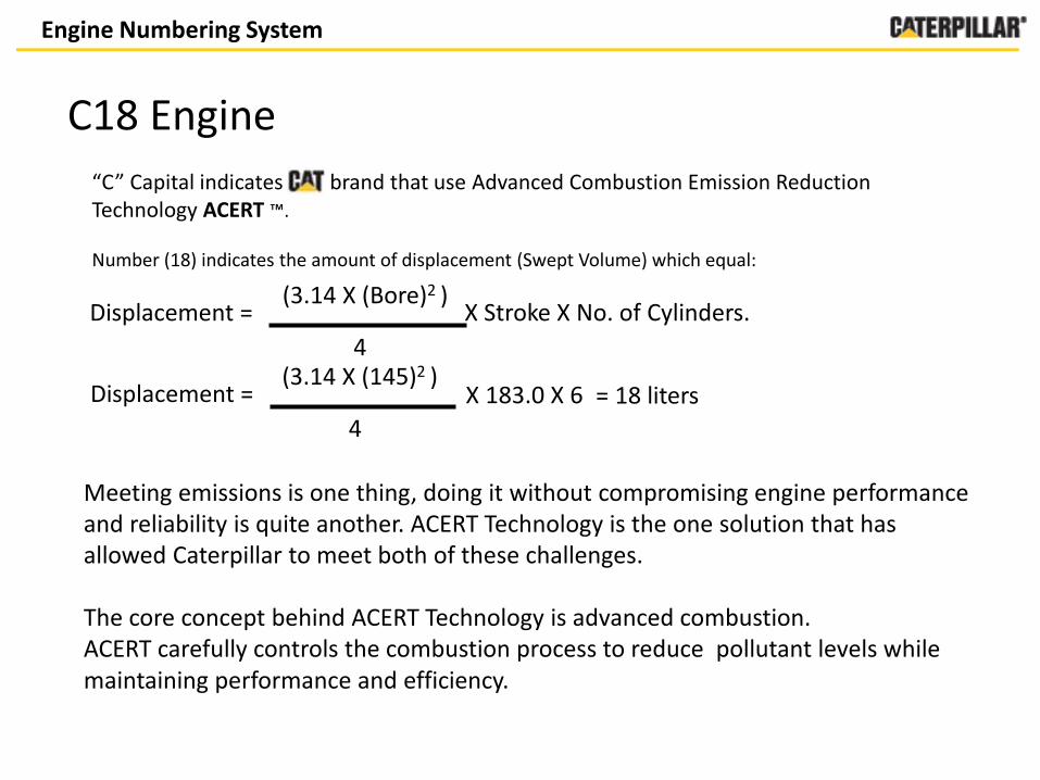
C18 Engine
“C” Capital indicates brand that use Advanced Combustion Emission Reduction Technology ACERT ™.
Number (18) indicates the amount of displacement (Swept Volume) which equal:
Displacement = X Stroke X No. of Cylinders. (3.14 X (Bore)2 )
4
Displacement = (3.14 X (145)2 )
4
X 183.0 X 6 = 18 liters
Meeting emissions is one thing, doing it without compromising engine performance and reliability is quite another. ACERT Technology is the one solution that has allowed Caterpillar to meet both of these challenges.
The core concept behind ACERT Technology is advanced combustion.ACERT carefully controls the combustion process to reduce pollutant levels while maintaining performance and efficiency.

Contents
•About Engines- Cat® 3408C Engine- Cat® C18 Engine
•Engine Numbering System- Cat® 3408C Engine- Cat® C18 Engine
•Fuel System- Cat® 3408C Engine- Cat® C18 Engine
3408C Engine Fuel System
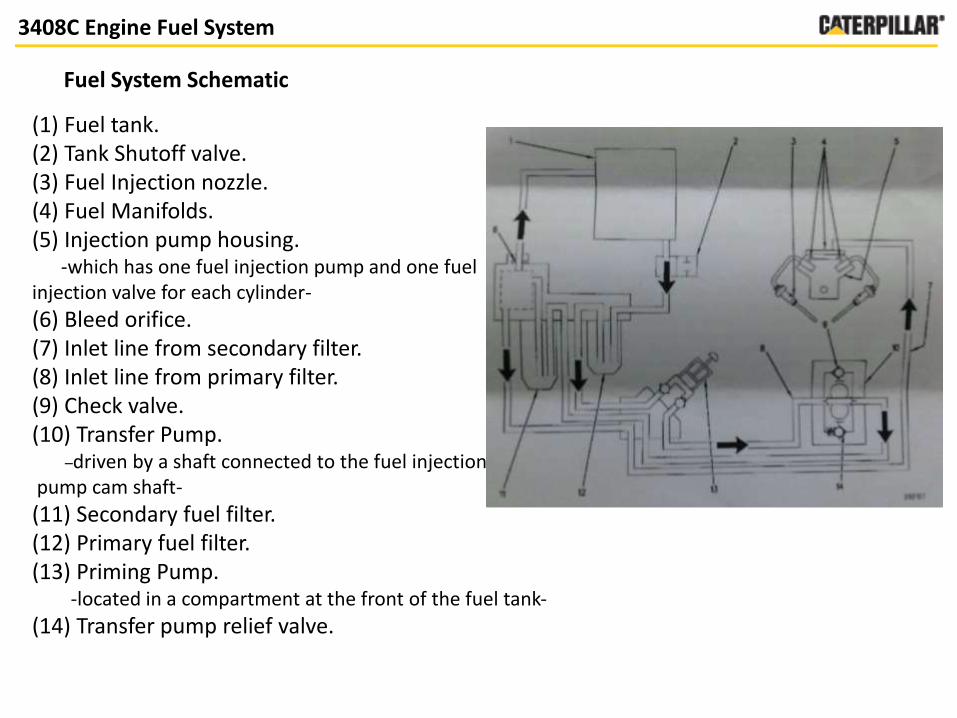
Fuel System Schematic
(1) Fuel tank.(2) Tank Shutoff valve. (3) Fuel Injection nozzle. (4) Fuel Manifolds.(5) Injection pump housing.
-which has one fuel injection pump and one fuel injection valve for each cylinder-
(6) Bleed orifice. (7) Inlet line from secondary filter. (8) Inlet line from primary filter.(9) Check valve.(10) Transfer Pump.
–driven by a shaft connected to the fuel injectionpump cam shaft-
(11) Secondary fuel filter.(12) Primary fuel filter. (13) Priming Pump.
-located in a compartment at the front of the fuel tank-
(14) Transfer pump relief valve.

Engine Build Locations
3408C Engine Fuel System
Fuel Injection Pump
(1) Fuel Manifolds(2) Inlet passage(3) Check valve(4) Pressure relief valve (5) pump plunger(6) Spring(7) Gear(8) Fuel rack (left)(9) Lifter(10) Link(11) Lever(12) Camshaft
The rotation of the lobes on camshaft causes lifters and pump plungers to move up and down, When the pump plunger is down, fuel goes to fill the chamber through passage.When the pump plunger is up, it closes the inlet passage.
3408C Engine Fuel System
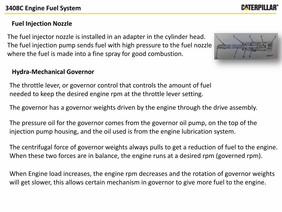
Fuel Injection Nozzle
The fuel injector nozzle is installed in an adapter in the cylinder head.The fuel injection pump sends fuel with high pressure to the fuel nozzle where the fuel is made into a fine spray for good combustion.
Hydra-Mechanical Governor
The throttle lever, or governor control that controls the amount of fuel needed to keep the desired engine rpm at the throttle lever setting.
The governor has a governor weights driven by the engine through the drive assembly.
The pressure oil for the governor comes from the governor oil pump, on the top of the injection pump housing, and the oil used is from the engine lubrication system.
The centrifugal force of governor weights always pulls to get a reduction of fuel to the engine. When these two forces are in balance, the engine runs at a desired rpm (governed rpm).
When Engine load increases, the engine rpm decreases and the rotation of governor weights will get slower, this allows certain mechanism in governor to give more fuel to the engine.
Contents
•About Engines- Cat® 3408C Engine- Cat® C18 Engine
•Engine Numbering System- Cat® 3408C Engine- Cat® C18 Engine
•Fuel System- Cat® 3408C Engine- Cat® C18 Engine

C12 Engine Fuel System
(1) Fuel supply line.(2) Units injectors-uses mechanical energy by camshaft (30000 psi)-
(3) Fuel manifolds(4) Differential pressure switch. (5) Fuel pressure sensor. (6) Fuel temperature sensor.(7) Fuel return line.(8) Pressure regulating valve.(9) Secondary fuel filter(10) Fuel filter base-used to remove abrasive material and contamination from fuel system-
(11) Fuel transfer pump(12) Electrical fuel primary pump-is used to evacuate the air from fuel system-
(13) Pressure relief valve (14) Primary fuel filter(15) Fuel tank(16) Fuel return line
Fuel System Schematic
Electronics Control Module (ECM) is the computer that is used to provide control for all aspects of engine operation;-maintains the desired engine speed by sensing the actual speed.-calculates the amount of fuel that needs to injected.All of these aspects to provide optimum performance of the engine
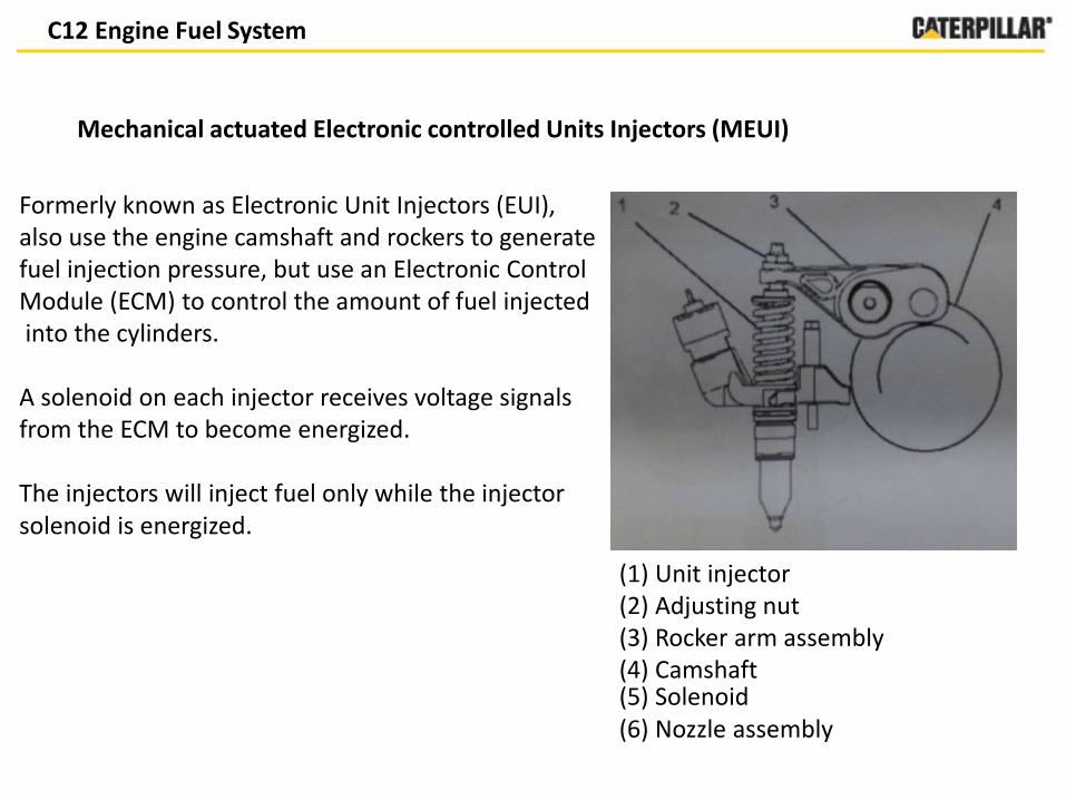
Mechanical actuated Electronic controlled Units Injectors (MEUI)
C12 Engine Fuel System
(1) Unit injector(2) Adjusting nut(3) Rocker arm assembly(4) Camshaft (5) Solenoid (6) Nozzle assembly
Formerly known as Electronic Unit Injectors (EUI), also use the engine camshaft and rockers to generate fuel injection pressure, but use an Electronic Control Module (ECM) to control the amount of fuel injectedinto the cylinders.
A solenoid on each injector receives voltage signals from the ECM to become energized.
The injectors will inject fuel only while the injector solenoid is energized.

Abstract
C183408C
ACERT™ U.S. EPA Tier 4 Final, EU Stage IV
Non-CertifiedAvailable for global non-
regulated areasEmission
Electronic control systemHydra-mechanical governorControl system
-MEUI Injection -Primary Fuel filter
-Secondary Fuel filters -Fuel transfer Pump
-Electronic fuel priming pump
-Primary Fuel filter -Secondary Fuel filters
-Fuel transfer pump-Manual fuel priming pump
Fuel system
Electrical unit injector (EUI)Fuel injection nozzleInjection unit


