34
C191HM POWERMETER AND HARMONIC MANAGER COMMUNICATIONS ASCII Communications Protocol REFERENCE GUIDE

C191HM POWERMETER AND HARMONIC
MANAGER
COMMUNICATIONS
ASCII Communications Protocol
REFERENCE GUIDE

2
Every effort has been made to ensure that the material herein is complete and accurate. However, the manufacturer is not responsible for any mistakes in printing or faulty instructions contained in this book. Notification of any errors or misprints will be received with appreciation. For further information regarding a particular installation, operation or maintenance of equipment, contact the manufacturer or your local representative or distributor. This book is copyrighted. No part of this book may be reproduced, stored in a retrieval system, or transmitted in any form or by any means, electronic, mechanical, photocopying, recording or otherwise without the prior written permission of the manufacturer. This revision is applicable to the C191HM instruments with firmware version 4.21 and later. COPYRIGHT 1999, 2003 BG0281 Rev.A2

3
Table of Contents
1 GENERAL...................................................................................................... 4 2 ASCII FRAMING ........................................................................................... 5 3 EXCEPTION RESPONSES ........................................................................... 7 4 SPECIFIC ASCII REQUESTS........................................................................ 8 4.1 Basic Data .............................................................................................................................. 8 4.2 Basic Setup .......................................................................................................................... 10 4.3 Instrument Status ................................................................................................................. 10 4.4 Reset/Clear Functions.......................................................................................................... 11 4.5 Reset the Instrument (warm restart) .................................................................................... 11 4.6 Read Firmware Version Number.......................................................................................... 12 4.7 Extended Instrument Status................................................................................................. 12 4.8 Analog Output Allocation...................................................................................................... 13 4.9 Digital Input Allocation.......................................................................................................... 15 4.10 Pulsing Setpoints................................................................................................................ 16 4.11 Min/Max Log....................................................................................................................... 16 4.12 Phase Harmonics ............................................................................................................... 17 5 DIRECT READ/WRITE REQUESTS............................................................ 19 5.1 General................................................................................................................................. 19 5.1.1 Long-Size Direct Read/Write............................................................................................. 19 5.1.2 Variable-Size Direct Read/Write ....................................................................................... 20 5.1.3 User Assignable Registers................................................................................................ 20 5.2 Extended Data Registers ..................................................................................................... 21 5.3 Basic Setup Registers .......................................................................................................... 26 5.4 User Selectable Options Setup ............................................................................................ 26 5.5 Communications Setup ........................................................................................................ 27 5.6 Alarm/Event Setpoints.......................................................................................................... 27 5.7 Relay Operation Control Registers ...................................................................................... 30 5.8 Instrument Options Registers............................................................................................... 31 5.9 Extended Status Registers................................................................................................... 31 5.10 Alarm Status Registers ...................................................................................................... 31 5.11 Reset/Synchronization Registers ....................................................................................... 32

4
1 GENERAL This document specifies the ASCII serial communications protocol used to transfer data between a master computer station and the C191HM. The document provides the complete information necessary to develop third-party communications software capable of communication with the Series C191HM instruments. All messages within the ASCII communications protocol are designed to consist only of printable characters. Additional information concerning communications operation, configuring the communications parameters and communications connections is found in "Series C191HM Powermeters, Installation and Operation Manual". IMPORTANT 1. In 3-wire connection schemes, the unbalanced current and phase readings for power factor, active
power, and reactive power will be zeros, because they have no meaning. Only the total three-phase power values can be used.
2. In 4LN3, 4LL3, 3LN3 and 3LL3 wiring modes, harmonic voltages will represent line-to-neutral voltages. In a 3-wire direct connection, harmonic voltages will represent line-to-neutral voltages as they appear on the instrument's input transformers. In a 3-wire open delta connection, harmonic voltages will comprise L12 and L23 line-to-line voltages.
5
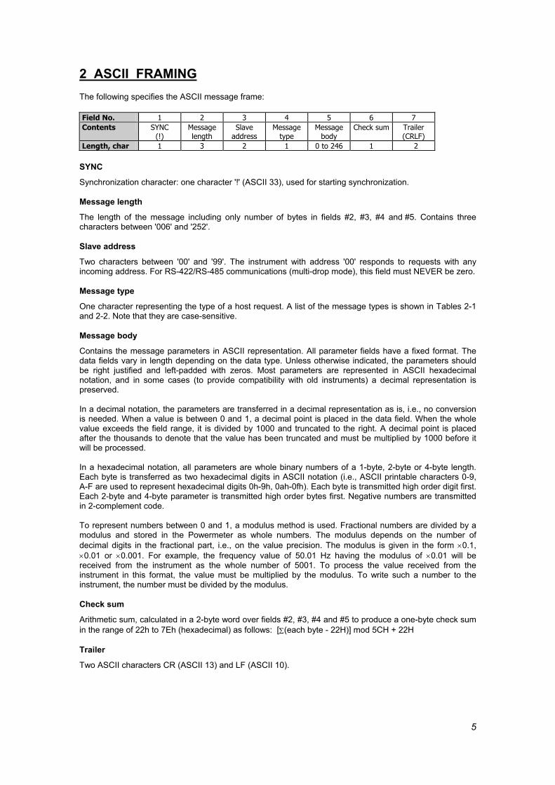
2 ASCII FRAMING The following specifies the ASCII message frame: Field No. 1 2 3 4 5 6 7 Contents SYNC
(!) Message length
Slave address
Message type
Message body
Check sum Trailer (CRLF)
Length, char 1 3 2 1 0 to 246 1 2 SYNC
Synchronization character: one character '!' (ASCII 33), used for starting synchronization. Message length
The length of the message including only number of bytes in fields #2, #3, #4 and #5. Contains three characters between '006' and '252'. Slave address
Two characters between '00' and '99'. The instrument with address '00' responds to requests with any incoming address. For RS-422/RS-485 communications (multi-drop mode), this field must NEVER be zero. Message type
One character representing the type of a host request. A list of the message types is shown in Tables 2-1 and 2-2. Note that they are case-sensitive. Message body
Contains the message parameters in ASCII representation. All parameter fields have a fixed format. The data fields vary in length depending on the data type. Unless otherwise indicated, the parameters should be right justified and left-padded with zeros. Most parameters are represented in ASCII hexadecimal notation, and in some cases (to provide compatibility with old instruments) a decimal representation is preserved. In a decimal notation, the parameters are transferred in a decimal representation as is, i.e., no conversion is needed. When a value is between 0 and 1, a decimal point is placed in the data field. When the whole value exceeds the field range, it is divided by 1000 and truncated to the right. A decimal point is placed after the thousands to denote that the value has been truncated and must be multiplied by 1000 before it will be processed. In a hexadecimal notation, all parameters are whole binary numbers of a 1-byte, 2-byte or 4-byte length. Each byte is transferred as two hexadecimal digits in ASCII notation (i.e., ASCII printable characters 0-9, A-F are used to represent hexadecimal digits 0h-9h, 0ah-0fh). Each byte is transmitted high order digit first. Each 2-byte and 4-byte parameter is transmitted high order bytes first. Negative numbers are transmitted in 2-complement code. To represent numbers between 0 and 1, a modulus method is used. Fractional numbers are divided by a modulus and stored in the Powermeter as whole numbers. The modulus depends on the number of decimal digits in the fractional part, i.e., on the value precision. The modulus is given in the form ×0.1, ×0.01 or ×0.001. For example, the frequency value of 50.01 Hz having the modulus of ×0.01 will be received from the instrument as the whole number of 5001. To process the value received from the instrument in this format, the value must be multiplied by the modulus. To write such a number to the instrument, the number must be divided by the modulus. Check sum
Arithmetic sum, calculated in a 2-byte word over fields #2, #3, #4 and #5 to produce a one-byte check sum in the range of 22h to 7Eh (hexadecimal) as follows: [Σ(each byte - 22H)] mod 5CH + 22H Trailer
Two ASCII characters CR (ASCII 13) and LF (ASCII 10).

6
NOTE
Fields #3 and #4 of the instrument response are always the same as those in the host request. Table 2-1 Specific ASCII Requests
Message type Description Char ASCII Hex
0 30h Read basic data registers 1 31h Read basic setup 2 32h Write basic setup 3 33h Read instrument status 4 34h Reset/clear functions 8 38h Reset the instrument 9 39h Read version number ? 3Fh Read extended status B 42h Read analog output allocation b 62h Write analog output allocation D 44h Read digital input allocation d 64h Write digital input allocation G 47h Read pulsing setpoint g 67h Write pulsing setpoint H 48h Read phase harmonics O 4Fh Read Min/Max log
Table 2-2 Direct Read/Write ASCII Requests
Message type Description Char ASCII Hex
A 41h Long-size direct read a 61h Long-size direct write X 58h Variable-size direct read x 78h Variable-size direct write

7
3 EXCEPTION RESPONSES The instrument will send the following error codes in the message body in response to incorrect host requests: XK - the instrument is in programming mode XM - invalid request type or illegal operation XP - invalid data address or data value, or data is not available NOTE
When a check or framing error is detected, the instrument will not act on or respond to the master's request.

8
4 SPECIFIC ASCII REQUESTS
4.1 Basic Data
Table 4-1 Read Request Message type (ASCII)
0 Message body (decimal)
Request - no body Response
Field Offset Length Parameter Unit Range 1 0 4 Voltage L1/L12 V/kV 0 to Vmax 2 4 4 Voltage L2/L21 V/kV 0 to Vmax 3 8 4 Voltage L3/L31 V/kV 0 to Vmax 4 12 5 Current L1 A 0 to Imax 5 17 5 Current L2 A 0 to Imax 6 22 5 Current L3 A 0 to Imax 7 27 6 kW L1 kW/MW -Pmax to Pmax 8 33 6 kW L2 kW/MW -Pmax to Pmax 9 39 6 kW L3 kW/MW -Pmax to Pmax 10 45 4 Power factor L1 -.99 to 1.00 11 49 4 Power factor L2 -.99 to 1.00 12 53 4 Power factor L3 -.99 to 1.00 13 57 6 kW total kW/MW -Pmax to Pmax 14 63 4 Power factor total -.99 to 1.00 15 67 6 kWh import MWh 0 to 99999. 16 73 5 Neutral (unbalanced) current A 0 to Imax 17 78 4 Frequency Hz 45.0 to 65.0 18 82 6 kvar L1 kvar/Mvar -Pmax to Pmax 19 88 6 kvar L2 kvar/Mvar -Pmax to Pmax 20 94 6 kvar L3 kvar/Mvar -Pmax to Pmax 21 100 6 kVA L1 kVA/MVA 0 to Pmax 22 106 6 kVA L2 kVA/MVA 0 to Pmax 23 112 6 kVA L3 kVA/MVA 0 to Pmax 24 118 6 kvarh net Mvarh -9999. to 99999. 25 124 6 kvar total kvar/Mvar -Pmax to Pmax 26 130 6 kVA total kVA/MVA 0 to Pmax 27 136 6 Maximum sliding window kW
demand kW/MW 0 to Pmax
28 142 6 Accum. kW demand kW/MW 0 to Pmax 29 148 5 Max. ampere demand L1 A 0 to Imax 30 153 5 Max. ampere demand L2 A 0 to Imax 31 158 5 Max. ampere demand L3 A 0 to Imax 32 163 2 Status inputs (hex) See Table 4-13 33 165 6 kWh export MWh 0 to 99999. 34 171 6 Maximum sliding window kVA
demand kVA/MVA 0 to Pmax
35 177 4 Voltage THD L1/L12 % 0.0 to 999. 36 181 4 Voltage THD L2/L23 % 0.0 to 999. 37 185 4 Voltage THD L3 % 0.0 to 999. 38 189 4 Current THD L1 % 0.0 to 999. 39 193 4 Current THD L2 % 0.0 to 999. 40 197 4 Current THD L3 % 0.0 to 999. 41 201 8 kVAh MVAh 0 to 99999.99 42 209 6 Present sliding window kW
demand kW/MW 0 to Pmax
43 215 6 Present sliding window kVA demand
kVA/MVA 0 to Pmax
44 221 4 PF at maximum KVA demand 0 to 1.00

9
45 225 4 Current TDD L1 % 0.0 to 99.9 46 229 4 Current TDD L2 % 0.0 to 99.9 47 233 4 Current TDD L3 % 0.0 to 99.9
Fields indicated by an N/A mark are padded with ASCII zeros. The parameter limits are as follows:
Imax (20% over-range) = 1.2 × CT primary current [A] Direct wiring (PT Ratio = 1):
Vmax (690 V input option) = 828.0 V Vmax (120 V input option) = 144.0 V Pmax = (Imax × Vmax × 3) [kW x 0.001] if wiring mode is 4LN3 or 3LN3 Pmax = (Imax × Vmax × 2) [kW x 0.001] if wiring mode is 4LL3, 3OP2, 3DIR2, 3OP3 or 3LL3
Wiring via PTs (PT Ratio > 1): Vmax (690 V input option) = 144 × PT Ratio [V] Vmax (120 V input option) = 144 × PT Ratio [V] Pmax = (Imax × Vmax × 3)/1000 [MW x 0.001] if wiring mode is 4LN3 or 3LN3 Pmax = (Imax × Vmax × 2)/1000 [MW x 0.001] if wiring mode is 4LL3, 3OP2, 3DIR2, 3OP3 or 3LL3
When ASCII compatibility mode is disabled (see Section 5.5), voltages, currents and powers are always transmitted with a decimal point at highest resolution available for the field. For direct wiring (PT Ratio = 1), voltages are transmitted in volts, currents in amperes, and powers in kilowatts. For wiring via PT (PT Ratio > 1), voltages are transmitted in kilovolts, currents in amperes, and powers in megawatts. When the value is greater than the field width, the right most digits of the fractional part are truncated. For the best available resolution, see Note to Table 5-7. When ASCII compatibility mode is enabled, the C191HM provides a fully downward-compatible response using a lower resolution for voltages, currents and powers - the value is transmitted as a whole number until the field is filled up, and then it is converted to higher units and transmitted with a decimal point (when the value is greater than the field width, the right most digits of the fractional part will be truncated). Voltages are transmitted in volts as whole numbers or in kilovolts with a decimal point, currents in amperes as whole numbers, and powers in kilowatts as whole numbers or in megawatts with a decimal point.
Energy readings are transmitted in MWh, Mvarh and MVAh units with a decimal point. If the energy value exceeds the field resolution, the right-most digits are truncated. The energy roll value is user selectable (see Section 5.4).
For negative power factor, the minus sign is transmitted before a decimal point as shown in the table. To get block interval demand readings, set the number of demand periods equal to 1 (see Table 4-4). When the 4LN3 or 3LN3 wiring mode is selected, the voltages will be line-to-neutral; for any other
wiring mode, they will be line-to-line voltages.

10
4.2 Basic Setup
Table 4-2 Read Request Message type (ASCII)
1 Message body (decimal)
Request Field Offset Length Parameter Range
1 0 3 Parameter identifier See Table 4-4 Response
Field Offset Length Parameter Range 1 0 3 Parameter identifier See Table 4-4 2 3 4 Not used Permanently set to 00.0 3 7 6 Parameter value See Table 4-4 Table 4-3 Write Request
Message type (ASCII) 2
Message body (decimal) Request/Response
Field Offset Length Parameter Range 1 0 3 Parameter identifier See Table 4-4 2 3 4 Not used Set to 00.0 3 7 6 Parameter value See Table 4-4 Table 4-4 Basic Setup Parameters
Parameter Identifier Range Wiring mode
W40 0 = 3OP2, 1 = 4LN3, 2 = 3DIR2, 3 = 4LL3, 4 = 3OP3, 5 = 3LN3, 6 = 3LL3
PT ratio U14 1.0 to 6500.0 CT primary current I17 1 to 6500 A Power demand period D11 1,2,5,10,15,20,30,60 min
255 = external synchronization The number of demand periods F47 1 - 15 Volt/ampere demand period C12 0 to 1800 sec Averaging buffer size S41 8, 16, 32 Reset enable/disable R42 0 = disable, 1 = enable Nominal frequency Q51 50, 60 Maximum demand load current Q52 0 to 6,500 A (0 = CT primary current)
The wiring mode options are as follows: 3OP2 - 3-wire open delta using 2 CTs (2 element) 4LN3 - 4-wire WYE using 3 PTs (3 element), line to neutral voltage readings 3DIR2 - 3-wire direct connection using 2 CTs (2 element) 4LL3 - 4-wire WYE using 3 PTs (3 element), line to line voltage readings 3OP3 - 3-wire open delta using 3 CTs (2 1/2 element) 3LN3 - 4-wire WYE using 2 PTs (2 1/2 element), line to neutral voltage readings 3LL3 - 4-wire WYE using 2 PTs (2 1/2 element), line to line voltage readings
Synchronization of power demand interval can be made through a digital input or via communications using the Synchronize power demand interval command (see Table 5-23)
4.3 Instrument Status This request is supported only for compatibility with older instruments. It allows to read the status of the first four relays. To read the status of the all eight relays, use the extended status request (see Section 4.7) or extended data registers (see Section 5.2).

11
Table 4-5 Read Request
Message type (ASCII) 3
Message body (hexadecimal) Request - no body
Response Field Offset Length Parameter Range
1 0 8 Not used 00000000 2 8 1 Not used 0 3 9 1 Relay status See Table 4-6
Table 4-6 Relay Status
Bit Description 0 Relay #4 status 1 Relay #3 status 2 Relay #2 status 3 Relay #1 status
Bit meaning: 0 = relay is energized, 1 = relay is not energized
4.4 Reset/Clear Functions These operations can be also performed by using the direct write requests instead of the specific request '4' (see Section 5.11). Table 4-7 Write Request
Message type (ASCII) 4
Message body (hexadecimal) Request/Response
Field Offset Length Parameter Range 1 0 1 Reset function See Table 4-8 2 1 2 Target See Table 4-8 (the field can be
omitted if it is equal to 0) Table 4-8 Reset/Clear Functions
Function Description Target 1 Clear total energy registers 0 2 Clear total maximum demand registers 0 = all maximum demands
1 = power demands 2 = volt/ampere demands
3-4 Reserved 5 Clear event/time counters 0 = all counters
1-4 = counter #1 - #4 6 Clear Min/Max log 0 7-F Reserved
4.5 Reset the Instrument (warm restart)
This request causes the instrument to perform full reset and restart, the same as when the instrument is turned on. No response is expected.

12
Table 4-9 Write Request Message type (ASCII)
8 Message body
Request - no body Response - no response
4.6 Read Firmware Version Number
Table 4-10 Read Request Message type (ASCII)
9 Message body (decimal)
Request - no body Response
Field Offset Length Parameter Range 1 0 3 Firmware version 300-399
4.7 Extended Instrument Status
Table 4-11 Read Request Message type (ASCII)
? Message body (hexadecimal)
Request - no body Response
Field Offset Length Parameter Range 1 0 4 Relay status See Table 4-12 2 4 4 Not used 0 3 8 4 Status inputs See Table 4-13 4 12 4 Setpoints status See Table 4-14 5 16 4 Log status See Table 4-15 6 20 36 Not used 0
Table 4-12 Relay Status
Bit Description 0 Relay #1 status 1 Relay #2 status 2 Relay #3 status 3 Relay #4 status 4 Relay #5 status 5 Relay #6 status 6 Relay #7 status 7 Relay #8 status 8-15 Not used (permanently set to 0)
Bit meaning: 0 = relay is not energized, 1 = relay is energized Table 4-13 Status Inputs
Bit Description 0 Status input 1-15 Not used (permanently set to 0)
Bit meaning: 0 = contact open, 1 = contact closed

13
Table 4-14 Setpoints Status Bit Description 0 Setpoint # 1 status 1 Setpoint # 2 status 2 Setpoint # 3 status 3 Setpoint # 4 status 4 Setpoint # 5 status 5 Setpoint # 6 status 6 Setpoint # 7 status 7 Setpoint # 8 status 8 Setpoint # 9 status 9 Setpoint # 10 status 10 Setpoint # 11 status 11 Setpoint # 12 status 12 Setpoint # 13 status 13 Setpoint # 14 status 14 Setpoint # 15 status 15 Setpoint # 16 status
Bit meaning: 0 = setpoint is released, 1 = setpoint is operated Table 4-15 Log Status
Bit Description 0 Reserved 1 New Min/Max log 2-15 Not used (permanently set to 0)
Bit meaning: 0 = no new logs, 1 = new log recorded (the new log flag is reset when the user reads the first log record after the flag has been set)
4.8 Analog Output Allocation
Table 4-16 Read Request Message type (ASCII)
B Message body (hexadecimal)
Request Field Offset Length Parameter Range
1 0 2 Analog channel number 0 Response
Field Offset Length Parameter Range 1 0 2 Analog channel number 0 2 2 4 Output parameter index See Table 4-18 3 6 8 Zero scale (0/4 mA) See Table 4-18 4 14 8 Full scale (20 mA) See Table 4-18 Table 4-17 Write Request
Message type (ASCII) b
Message body (hexadecimal) Request/Response
Field Offset Length Parameter Range 1 0 2 Analog channel number 0 2 2 4 Output parameter index See Table 4-18 3 6 8 Zero scale (0/4 mA) See Table 4-18 4 14 8 Full scale (20 mA) See Table 4-18
Except for the signed power factor (see Note 3 to Table 4-18), the output scale is linear within the value range. The scale range will be inverted if the full scale specified is less than the zero scale.
14
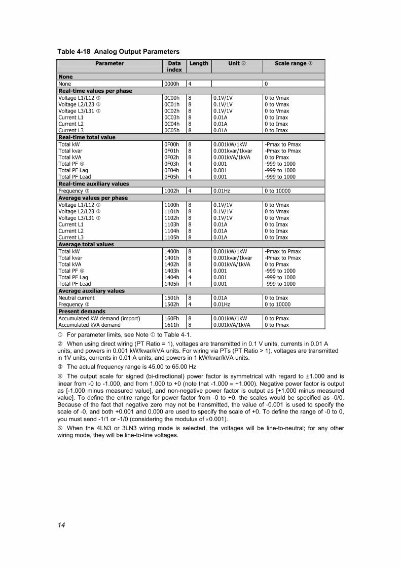
Table 4-18 Analog Output Parameters Parameter Data
index Length Unit Scale range
None None 0000h 4 0 Real-time values per phase Voltage L1/L12 0C00h 8 0.1V/1V 0 to Vmax Voltage L2/L23 0C01h 8 0.1V/1V 0 to Vmax Voltage L3/L31 0C02h 8 0.1V/1V 0 to Vmax Current L1 0C03h 8 0.01A 0 to Imax Current L2 0C04h 8 0.01A 0 to Imax Current L3 0C05h 8 0.01A 0 to Imax Real-time total value Total kW 0F00h 8 0.001kW/1kW -Pmax to Pmax Total kvar 0F01h 8 0.001kvar/1kvar -Pmax to Pmax Total kVA 0F02h 8 0.001kVA/1kVA 0 to Pmax Total PF 0F03h 4 0.001 -999 to 1000 Total PF Lag 0F04h 4 0.001 -999 to 1000 Total PF Lead 0F05h 4 0.001 -999 to 1000 Real-time auxiliary values Frequency 1002h 4 0.01Hz 0 to 10000 Average values per phase Voltage L1/L12 1100h 8 0.1V/1V 0 to Vmax Voltage L2/L23 1101h 8 0.1V/1V 0 to Vmax Voltage L3/L31 1102h 8 0.1V/1V 0 to Vmax Current L1 1103h 8 0.01A 0 to Imax Current L2 1104h 8 0.01A 0 to Imax Current L3 1105h 8 0.01A 0 to Imax Average total values Total kW 1400h 8 0.001kW/1kW -Pmax to Pmax Total kvar 1401h 8 0.001kvar/1kvar -Pmax to Pmax Total kVA 1402h 8 0.001kVA/1kVA 0 to Pmax Total PF 1403h 4 0.001 -999 to 1000 Total PF Lag 1404h 4 0.001 -999 to 1000 Total PF Lead 1405h 4 0.001 -999 to 1000 Average auxiliary values Neutral current 1501h 8 0.01A 0 to Imax Frequency 1502h 4 0.01Hz 0 to 10000 Present demands Accumulated kW demand (import) 160Fh 8 0.001kW/1kW 0 to Pmax Accumulated kVA demand 1611h 8 0.001kVA/1kVA 0 to Pmax
For parameter limits, see Note to Table 4-1. When using direct wiring (PT Ratio = 1), voltages are transmitted in 0.1 V units, currents in 0.01 A
units, and powers in 0.001 kW/kvar/kVA units. For wiring via PTs (PT Ratio > 1), voltages are transmitted in 1V units, currents in 0.01 A units, and powers in 1 kW/kvar/kVA units.
The actual frequency range is 45.00 to 65.00 Hz The output scale for signed (bi-directional) power factor is symmetrical with regard to ±1.000 and is
linear from -0 to -1.000, and from 1.000 to +0 (note that -1.000 ≡ +1.000). Negative power factor is output as [-1.000 minus measured value], and non-negative power factor is output as [+1.000 minus measured value]. To define the entire range for power factor from -0 to +0, the scales would be specified as -0/0. Because of the fact that negative zero may not be transmitted, the value of -0.001 is used to specify the scale of -0, and both +0.001 and 0.000 are used to specify the scale of +0. To define the range of -0 to 0, you must send -1/1 or -1/0 (considering the modulus of ×0.001).
When the 4LN3 or 3LN3 wiring mode is selected, the voltages will be line-to-neutral; for any other wiring mode, they will be line-to-line voltages.

15
4.9 Digital Input Allocation
Table 4-19 Read Request Message type (ASCII)
D Message body (hexadecimal)
Request Field Offset Length Parameter Range
1 0 2 Digital input group ID See Table 4-21 Response
Field Offset Length Parameter Range 1 0 2 Digital input group ID See Table 4-21 2 2 2 Allocation mask See Table 4-22 Table 4-20 Write Request
Message type (ASCII) d
Message body (hexadecimal) Request/Response
Field Offset Length Parameter Range 1 0 2 Digital input group ID See Table 4-21 2 2 2 Allocation mask See Table 4-22 Table 4-21 Digital Input Groups Group ID Description 0 Status inputs 1 Pulse inputs 2 Not used (read as 0) 3 External synchronization pulse input
Writing to these locations is ignored. No error will occur.
NOTE When a digital input is allocated for the external synchronization pulse, it is automatically configured as a pulse input, otherwise it is configured as a status input. Table 4-22 Digital Inputs Allocation Mask
Bit number Description 0 Digital input allocation status 1-15 Not used
Bit meaning: 0 = input not allocated, 1 = input allocated to the group

16
4.10 Pulsing Setpoints
Table 4-23 Read Request Message type (ASCII)
G Message body (hexadecimal)
Request Field Offset Length Parameter Range
1 0 2 Pulse output ID 0-7 (see Table 4-25) Response
Field Offset Length Parameter Range 1 0 2 Pulse output ID 0-7 (see Table 4-25) 2 2 2 Output parameter ID See Table 4-26 3 4 4 For energy pulsing =
number of unit-hours per pulse, otherwise - permanently set to 0
0-9999
Table 4-24 Write Request
Message type (ASCII) g
Message body (hexadecimal) Request/Response
Field Offset Length Parameter Range 1 0 2 Pulse output ID 0-7 (see Table 4-25) 2 2 2 Output parameter ID See Table 4-26 3 4 4 For energy pulsing = number of unit-
hours per pulse, otherwise - set to 0 0-9999
Table 4-25 Pulse Outputs Pulsing output ID Output allocation 0 Relay #1 1 Relay #2 2 Relay #3 3 Relay #4 4 Relay #5 5 Relay #6 6 Relay #7 7 Relay #8
Table 4-26 Pulsing Output Parameters
Pulsing parameter ID Identifier None 0 kWh import 1 kWh export 2 kvarh import 4 kvarh export 5 kvarh total (absolute) 6 kVAh total 7
4.11 Min/Max Log The Min/Max log read request is supported only for compatibility with other models of instruments. Because the Min/Max log is not time stamped in the C191HM, this request yields only the Min/Max log parameters which can be read directly via extended data registers (see Table 5-7).

17
Table 4-27 Read Request Message type (ASCII)
O Message body (hexadecimal)
Request Field Offset Length Parameter Range
1 0 4 Start Min/Max parameter ID See Table 5-7 2 4 2 The number of subsequent parameters to read 1-12
Response Field Offset Length Parameter Range 1 0 2 The number of parameters in message 1-12 2 2 2 Log parameter #1 Second 0 3 4 2 Minute 0 4 6 2 Hour 0 5 8 2 Day 0 6 10 2 Month 0 7 12 2 Year 0 8 14 8 Parameter value See Table 5-7 9 22 2 Log parameter #2 Second 0 10 24 2 Minute 0 11 26 2 Hour 0 12 28 2 Day 0 13 30 2 Month 0 14 32 2 Year 0 15 34 8 Parameter value See Table 5-7 . . . 79 222 2 Log parameter #12 Second 0 80 224 2 Minute 0 81 226 2 Hour 0 82 228 2 Day 0 83 230 2 Month 0 84 232 2 Year 0 85 234 8 Parameter value See Table 5-7
This request allows you to obtain the Min/Max log parameters. Up to 12 parameters can be read in one packet from a single parameter group. The available Min/Max log parameters are listed in Table 5-7. The time stamp is not available in the C191HM and is padded with zeros.
4.12 Phase Harmonics
Table 4-28 Read Request Message type (ASCII)
H Message body (decimal)
Request Field Offset Length Parameter Range
1 0 1 Channel ID 1 - 6 (see Table 4-29) Response
Field Offset Length Parameter Range 1 0 5 RMS value for the channel , V/A 0 to Vmax /Imax 2 5 5 Fundamental frequency 0 to 65.50 3 10 5 %THD 0.0 to 100.0 4 15 5 Harmonic H01 (reference) 100.0 5 20 5 Harmonic H02 0.00 to 100.0 6 25 5 Harmonic H03 0.00 to 100.0 ... 43 210 5 Harmonic H40 0.00 to 100.0
Phase voltage will be line-to-line voltage in 3OP2 and 3OP3 wiring modes, and line-to-neutral voltage in other configurations.
For RMS value representation, see Note to Table 4-1.

18
Table 4-29 Harmonic Spectrum Channels Channel ID Description
1 Voltage L1/L12 2 Voltage L2/L23 3 Voltage L3 4 Current L1 5 Current L2 6 Current L3

19
5 DIRECT READ/WRITE REQUESTS
5.1 General This chapter describes the instrument data locations that are addressed directly using data location indexes. These locations can be accessed by using universal direct read/write requests instead of specific ASCII requests. A data index is a 4-digit hexadecimal number, which actually comprises a two-digit data group identifier followed by a two-digit location offset within a group. All data are transmitted in ASCII hexadecimal notation. Negative numbers are transmitted in 2-complement code. 5.1.1 Long-Size Direct Read/Write
Table 5-1 Read Request Message type (ASCII)
A Message body (hexadecimal)
Request Field Offset Length Parameter Range 1 0 4 Start data index to read 0000h - FFFFh 2 4 2 The number of contiguous data items to read 1-30 (01h - 1Eh)
Response Field Offset Length Parameter Range 1 0 2 Number of data items in the message 1-30 (01h - 1Eh) 2 2 8 Data #1 value 3 10 8 Data #2 value ... ... ... ... 31 234 8 Data #30 value
Table 5-2 Write Request
Message type (ASCII) a
Message body (hexadecimal) Request/Response
Field Offset Length Parameter Range 1 0 4 Data index to write 0000h - FFFFh 2 4 8 Data value to write
In long-size direct read/write messages, all data items are read and written as long signed integers, which are represented in messages by 8-digit hexadecimal numbers, regardless of the actual data size. By using a long-size direct read request, up to 30 contiguous parameters can be read at once. A write request allows for writing only one data location at a time.

20
5.1.2 Variable-Size Direct Read/Write
Table 5-3 Read Request Message type (ASCII)
X Message body (hexadecimal)
Request Field Offset Length Parameter Range 1 0 4 Start data index to read 0000h - FFFFh 2 4 2 The number of contiguous data items to read 1-61 (01h - 3Dh)
Response Field Offset Length Parameter Range 1 0 2 Number of data items in the message 1-61 (01h - 3Dh) 2 2 2/4/8 Data #1 value 3 2/4/8 Data #2 value ... ... ... ... 60 2/4/8 Data #60 value
Table 5-4 Write Request
Message type (ASCII) x
Message body (hexadecimal) Request
Field Offset Length Parameter Range 1 0 4 Start data index to write 0000h - FFFFh 2 4 2 The number of contiguous data items to write 1-61 (01h - 3Dh) 2 2 2/4/8 Data #1 value 3 2/4/8 Data #2 value ... ... ... ... 60 2/4/8 Data #60 value
Request Field Offset Length Parameter Range 1 0 4 Start data index written 0000h - FFFFh 2 4 2 The number of data items written 1-61 (01h - 3Dh)
With variable-size direct read/write messages, data items are read and written as 2, 4 or 8-character hexadecimal numbers. The actual data size is indicated for each data location. When written, the data format should be exactly the same as indicated. The number of parameters that can be read or written by a single read/write request depends on the size of each data item. The total length of all parameters should not exceed 240 characters. 5.1.3 User Assignable Registers
The instrument contains 120 user assignable registers in the range of indexes 8000h to 8077h (see Table 5-5). You can map any of these registers to either register index, accessible in the instrument through direct read/write requests. Registers that reside in different locations may be accessed by a single request by re-mapping them to adjacent addresses in the user assignable registers area. The actual indexes of the user assignable registers which are accessed via indexes 8000h to 8077h are specified in the user assignable register map. It occupies indexes 8100h to 8177h (see Table 5-6), where the map register 8100h should contain the actual index of the register accessed via assignable register 8000h, register 8101h should contain the actual index of the register accessed via assignable register 8001h, and so on. Note that the user assignable register indexes and the user register map indexes may not be re-mapped.

21
Table 5-5 User Assignable Registers Data index
(hex) Register contents Length Direction Range
8000h User definable data 0 8001h User definable data 1 8002h ...
User definable data 2 ...
...
8077h User definable data 119
- depends on the mapped register Table 5-6 User Assignable Register Map
Data index (hex)
Register contents Length Direction Range
8100h Data index for user data 0 4 R/W 0000h-FFFFh 8101h Data index for user data 1 4 R/W 0000h-FFFFh 8102h ...
Data index for user data 2 ...
4 ...
R/W 0000h-FFFFh
8177h Data index for user data 119 4 R/W 0000h-FFFFh
To build your own register map, write to map registers (8100h to 8177h) the actual addresses you want to read from or write to via the assignable area (8000h to 8077h). For example, if you want to read registers 0C00h (real-time voltage of phase A) and 1700h (kWh import) via indexes 8000h-8001h, do the following:
- write 0C00h to register 8100h - write 1700h to register 8101h
Reading from registers 8000h-8001h will return the voltage reading in register 8000h, and the kWh reading in register 8001h.
5.2 Extended Data Registers
Table 5-7 Extended Data Table Parameter Data
index Length Direction Unit Range
None None 0000h 4 R 0 Status inputs Status inputs 0600h 4 R See Table 4-13 Relays Relay status 0800h 4 R See Table 4-12 Event/time counters Pulse counter #1 0A00h 8 R/W 0 to 99999 Pulse counter #2 0A01h 8 R/W 0 to 99999 Pulse counter #3 0A02h 8 R/W 0 to 99999 Pulse counter #4 0A03h 8 R/W 0 to 99999 Real-time values per phase Voltage L1/L12 0C00h 8 R 0.1V/1V 0 to Vmax Voltage L2/L23 0C01h 8 R 0.1V/1V 0 to Vmax Voltage L3/L31 0C02h 8 R 0.1V/1V 0 to Vmax Current L1 0C03h 8 R 0.01A 0 to Imax Current L2 0C04h 8 R 0.01A 0 to Imax Current L3 0C05h 8 R 0.01A 0 to Imax kW L1 0C06h 8 R 0.001kW/1kW -Pmax to Pmax kW L2 0C07h 8 R 0.001kW/1kW -Pmax to Pmax kW L3 0C08h 8 R 0.001kW/1kW -Pmax to Pmax kvar L1 0C09h 8 R 0.001kvar/1kvar -Pmax to Pmax kvar L2 0C0Ah 8 R 0.001kvar/1kvar -Pmax to Pmax kvar L3 0C0Bh 8 R 0.001kvar/1kvar -Pmax to Pmax kVA L1 0C0Ch 8 R 0.001kVA/1kVA 0 to Pmax kVA L2 0C0Dh 8 R 0.001kVA/1kVA 0 to Pmax kVA L3 0C0Eh 8 R 0.001kVA/1kVA 0 to Pmax

22
Parameter Data index
Length Direction Unit Range
Power factor L1 0C0Fh 4 R 0.001 -999 to 1000 Power factor L2 0C10h 4 R 0.001 -999 to 1000 Power factor L3 0C11h 4 R 0.001 -999 to 1000 Voltage THD L1/L12 0C12h 4 R 0.1% 0 to 9999 Voltage THD L2/L23 0C13h 4 R 0.1% 0 to 9999 Voltage THD L3 0C14h 4 R 0.1% 0 to 9999 Current THD L1 0C15h 4 R 0.1% 0 to 9999 Current THD L2 0C16h 4 R 0.1% 0 to 9999 Current THD L3 0C17h 4 R 0.1% 0 to 9999 K-Factor L1 0C18h 4 R 0.1 10 to 9999 K-Factor L2 0C19h 4 R 0.1 10 to 9999 K-Factor L3 0C1Ah 4 R 0.1 10 to 9999 Current TDD L1 0C1Bh 4 R 0.1% 0 to 1000 Current TDD L2 0C1Ch 4 R 0.1% 0 to 1000 Current TDD L3 0C1Dh 4 R 0.1% 0 to 1000 Voltage L12 0C1Eh 8 R 0.1V/1V 0 to Vmax Voltage L23 0C1Fh 8 R 0.1V/1V 0 to Vmax Voltage L31 0C20h 8 R 0.1V/1V 0 to Vmax Real-time total values Total kW 0F00h 8 R 0.001kW/1kW -Pmax to Pmax Total kvar 0F01h 8 R 0.001kvar/1kvar -Pmax to Pmax Total kVA 0F02h 8 R 0.001kVA/1kVA 0 to Pmax Total PF 0F03h 4 R 0.001 -999 to 1000 Reserved 0F04h 4 R 0 Reserved 0F05h 4 R 0 Real-time auxiliary values Reserved 1000h 8 R 0 Neutral current 1001h 8 R 0.01A 0 to Imax Frequency 1002h 4 R 0.01Hz 0 to 10000 Voltage unbalance 1003h 4 R 1% 0 to 300 Current unbalance 1004h 4 R 1% 0 to 300 Average values per phase Voltage L1/L12 1100h 8 R 0.1V/1V 0 to Vmax Voltage L2/L23 1101h 8 R 0.1V/1V 0 to Vmax Voltage L3/L31 1102h 8 R 0.1V/1V 0 to Vmax Current L1 1103h 8 R 0.01A 0 to Imax Current L2 1104h 8 R 0.01A 0 to Imax Current L3 1105h 8 R 0.01A 0 to Imax kW L1 1106h 8 R 0.001kW/1kW -Pmax to Pmax kW L2 1107h 8 R 0.001kW/1kW -Pmax to Pmax kW L3 1108h 8 R 0.001kW/1kW -Pmax to Pmax kvar L1 1109h 8 R 0.001kvar/1kvar -Pmax to Pmax kvar L2 110Ah 8 R 0.001kvar/1kvar -Pmax to Pmax kvar L3 110Bh 8 R 0.001kvar/1kvar -Pmax to Pmax kVA L1 110Ch 8 R 0.001kVA/1kVA 0 to Pmax kVA L2 110Dh 8 R 0.001kVA/1kVA 0 to Pmax kVA L3 110Eh 8 R 0.001kVA/1kVA 0 to Pmax Power factor L1 110Fh 4 R 0.001 -999 to 1000 Power factor L2 1110h 4 R 0.001 -999 to 1000 Power factor L3 1111h 4 R 0.001 -999 to 1000 Voltage THD L1/L12 1112h 4 R 0.1% 0 to 9999 Voltage THD L2/L23 1113h 4 R 0.1% 0 to 9999 Voltage THD L3 1114h 4 R 0.1% 0 to 9999 Current THD L1 1115h 4 R 0.1% 0 to 9999 Current THD L2 1116h 4 R 0.1% 0 to 9999 Current THD L3 1117h 4 R 0.1% 0 to 9999 K-Factor L1 1118h 4 R 0.1 10 to 9999 K-Factor L2 1119h 4 R 0.1 10 to 9999 K-Factor L3 111Ah 4 R 0.1 10 to 9999 Current TDD L1 111Bh 4 R 0.1% 0 to 1000 Current TDD L2 111Ch 4 R 0.1% 0 to 1000 Current TDD L3 111Dh 4 R 0.1% 0 to 1000 Voltage L12 110Eh 8 R 0.1V/1V 0 to Vmax Voltage L23 110Fh 8 R 0.1V/1V 0 to Vmax Voltage L31 1120h 8 R 0.1V/1V 0 to Vmax

23
Parameter Data index
Length Direction Unit Range
Average total values Total kW 1400h 8 R 0.001kW/1kW -Pmax to Pmax Total kvar 1401h 8 R 0.001kvar/1kvar -Pmax to Pmax Total kVA 1402h 8 R 0.001kVA/1kVA 0 to Pmax Total PF 1403h 4 R 0.001 -999 to 1000 Reserved 1404h 4 R 0 Reserved 1405h 4 R 0 Average auxiliary values Reserved 1500h 8 R 0 Neutral current 1501h 8 R 0.01A 0 to Imax Frequency 1502h 4 R 0.01Hz 0 to 10000 Voltage unbalance 1503h 4 R 1% 0 to 300 Current unbalance 1504h 4 R 1% 0 to 300 Present demands Volt demand L1/L12 1600h 8 R 0.1V/1V 0 to Vmax Volt demand L2/L23 1601h 8 R 0.1V/1V 0 to Vmax Volt demand L3/L31 1602h 8 R 0.1V/1V 0 to Vmax Ampere demand L1 1603h 8 R 0.01A 0 to Imax Ampere demand L2 1604h 8 R 0.01A 0 to Imax Ampere demand L3 1605h 8 R 0.01A 0 to Imax Block kW demand 1606h 8 R 0.001kW/1kW 0 to Pmax Reserved 1607h 8 R 0 Block kVA demand 1608h 8 R 0.001kVA/1kVA 0 to Pmax Sliding window kW demand 1609h 8 R 0.001kW/1kW 0 to Pmax Reserved 160Ah 8 R 0 Sliding window kVA demand 160Bh 8 R 0.001kVA/1kVA 0 to Pmax Reserved 160Ch 8 R 0 Reserved 160Dh 8 R 0 Reserved 160Eh 8 R 0 Accumulated kW demand 160Fh 8 R 0.001kW/1kW 0 to Pmax Reserved 1610h 8 R 0 Accumulated kVA demand 1611h 8 R 0.001kVA/1kVA 0 to Pmax Predicted sliding window kW demand
1612h 8 R 0.001kW/1kW 0 to Pmax
Reserved 1613h 8 R 0 Predicted sliding window kVA demand
1614h 8 R 0.001kVA/1kVA 0 to Pmax
PF at maximum sliding window kVA demand
1615h 4 R 0.001 0 to 1000
Total energies kWh import 1700h 8 R kWh 0 to 108-1 kWh export 1701h 8 R kWh 0 to 108-1 Reserved 1702h 8 R 0 Reserved 1703h 8 R 0 kvarh import 1704h 8 R kvarh 0 to 108-1 kvarh export 1705h 8 R kvarh 0 to 108-1 Reserved 1706h 8 R 0 Reserved 1707h 8 R 0 kVAh total 1708h 8 R kVAh 0 to 108-1 Phase energies kWh import L1 1800h 8 R kWh 0 to 108-1 kWh import L2 1801h 8 R kWh 0 to 108-1 kWh import L3 1802h 8 R kWh 0 to 108-1 kvarh import (inductive) L1 1803h 8 R kvarh 0 to 108-1 kvarh import (inductive) L2 1804h 8 R kvarh 0 to 108-1 kvarh import (inductive) L3 1805h 8 R kvarh 0 to 108-1 kVAh L1 1806h 8 R kVAh 0 to 108-1 kVAh L2 1807h 8 R kVAh 0 to 108-1 kVAh L3 1808h 8 R kVAh 0 to 108-1 L1/L12 phase voltage harmonics Harmonic H01 1900h 4 R 0.01% 0 to 10000 Harmonic H02 1901h 4 R 0.01% 0 to 10000 . . . . . . Harmonic H40 1927h 4 R 0.01% 0 to 10000

24
Parameter Data index
Length Direction Unit Range
L2/L23 phase voltage harmonics Harmonic H01 1A00h 4 R 0.01% 0 to 10000 Harmonic H02 1A01h 4 R 0.01% 0 to 10000 . . . . . . Harmonic H40 1A27h 4 R 0.01% 0 to 10000 L3 phase voltage harmonics Harmonic H01 1B00h 4 R 0.01% 0 to 10000 Harmonic H02 1B01h 4 R 0.01% 0 to 10000 . . . . . . Harmonic H40 1B27h 4 R 0.01% 0 to 10000 L1 phase current harmonics Harmonic H01 1C00h 4 R 0.01% 0 to 10000 Harmonic H02 1C01h 4 R 0.01% 0 to 10000 . . . . . . Harmonic H40 1C27h 4 R 0.01% 0 to 10000 L2 phase current harmonics Harmonic H01 1D00h 4 R 0.01% 0 to 10000 Harmonic H02 1D01h 4 R 0.01% 0 to 10000 . . . . . . Harmonic H40 1D27h 4 R 0.01% 0 to 10000 L3 phase current harmonics Harmonic H01 1E00h 4 R 0.01% 0 to 10000 Harmonic H02 1E01h 4 R 0.01% 0 to 10000 . . . . . . Harmonic H40 1E27h 4 R 0.01% 0 to 10000 Fundamental's (H01) real-time values per phase Voltage L1/L12 2900h 8 R 0.1V/1V 0 to Vmax Voltage L2/L23 2901h 8 R 0.1V/1V 0 to Vmax Voltage L3/L31 2902h 8 R 0.1V/1V 0 to Vmax Current L1 2903h 8 R 0.01A 0 to Imax Current L2 2904h 8 R 0.01A 0 to Imax Current L3 2905h 8 R 0.01A 0 to Imax kW L1 2906h 8 R 0.001kW/1kW -Pmax to Pmax kW L2 2907h 8 R 0.001kW/1kW -Pmax to Pmax kW L3 2908h 8 R 0.001kW/1kW -Pmax to Pmax kvar L1 2909h 8 R 0.001kvar/1kvar -Pmax to Pmax kvar L2 290Ah 8 R 0.001kvar/1kvar -Pmax to Pmax kvar L3 290Bh 8 R 0.001kvar/1kvar -Pmax to Pmax kVA L1 290Ch 8 R 0.001kVA/1kVA 0 to Pmax kVA L2 290Dh 8 R 0.001kVA/1kVA 0 to Pmax kVA L3 290Eh 8 R 0.001kVA/1kVA 0 to Pmax Power factor L1 290Fh 4 R 0.001 -999 to 1000 Power factor L2 2910h 4 R 0.001 -999 to 1000 Power factor L3 2911h 4 R 0.001 -999 to 1000 Fundamental's (H01) real-time total values Total kW 2a00h 8 R 0.001kW/1kW -Pmax to Pmax Total kvar 2a01h 8 R 0.001kvar/1kvar -Pmax to Pmax Total kVA 2a02h 8 R 0.001kVA/1kVA 0 to Pmax Total PF 2a03h 4 R 0.001 -999 to 1000 Minimum real-time values per phase (M) Voltage L1/L12 2C00h 8 R 0.1V/1V 0 to Vmax Voltage L2/L23 2C01h 8 R 0.1V/1V 0 to Vmax Voltage L3/L31 2C02h 8 R 0.1V/1V 0 to Vmax Current L1 2C03h 8 R 0.01A 0 to Imax Current L2 2C04h 8 R 0.01A 0 to Imax Current L3 2C05h 8 R 0.01A 0 to Imax Minimum real-time total values (M) Total kW 2D00h 8 R 0.001kW/1kW -Pmax to Pmax Total kvar 2D01h 8 R 0.001kvar/1kvar -Pmax to Pmax Total kVA 2D02h 8 R 0.001kVA/1kVA 0 to Pmax Total PF 2D03h 4 R 0.001 0 to 1000 Minimum real-time auxiliary values (M) Reserved 2E00h 8 R 0 Neutral current 2E01h 8 R 0.01A 0 to Imax

25
Parameter Data index
Length Direction Unit Range
Frequency 2E02h 4 R 0.01Hz 0 to 10000 Minimum demands (M) - Reserved Reserved 2F00h-
2F0Bh 8 R 0
Maximum real-time values per phase (M) Voltage L1/L12 3400h 8 R 0.1V/1V 0 to Vmax Voltage L2/L23 3401h 8 R 0.1V/1V 0 to Vmax Voltage L3/L31 3402h 8 R 0.1V/1V 0 to Vmax Current L1 3403h 8 R 0.01A 0 to Imax Current L2 3404h 8 R 0.01A 0 to Imax Current L3 3405h 8 R 0.01A 0 to Imax Maximum real-time total values (M) Total kW 3500h 8 R 0.001kW/1kW -Pmax to Pmax Total kvar 3501h 8 R 0.001kvar/1kvar -Pmax to Pmax Total kVA 3502h 8 R 0.001kVA/1kVA 0 to Pmax Total PF 3503h 4 R 0.001 0 to 1000 Maximum real-time auxiliary values (M) Reserved 3600h 8 R 0 Neutral current 3601h 8 R 0.01A 0 to Imax Frequency 3602h 4 R 0.01Hz 0 to 10000 Maximum demands (M) Max. volt demand L1/L12 3700h 8 R 0.1V/1V 0 to Vmax Max. volt demand L2/L23 3701h 8 R 0.1V/1V 0 to Vmax Max. volt demand L3/L31 3702h 8 R 0.1V/1V 0 to Vmax Max. ampere demand L1 3703h 8 R 0.01A 0 to Imax Max. ampere demand L2 3704h 8 R 0.01A 0 to Imax Max. ampere demand L3 3705h 8 R 0.01A 0 to Imax Reserved 3706h 8 R 0 Reserved 3707h 8 R 0 Reserved 3708h 8 R 0 Max. sliding window kW demand 3709h 8 R 0.001kW/1kW 0 to Pmax Reserved 370Ah 8 R 0 Max. sliding window kVA demand 370Bh 8 R 0.001kVA/1kVA 0 to Pmax L1/L12 voltage harmonic angles Harmonic H01 angle 6400h 4 R 0.1 degree -1800 to 1800 Harmonic H02 angle 6401h 4 R 0.1 degree -1800 to 1800 . . . . . . Harmonic H40 angle 6427h 4 R 0.1 degree -1800 to 1800 L2/L23 voltage harmonic angles Harmonic H01 angle 6500h 4 R 0.1 degree -1800 to 1800 Harmonic H02 angle 6501h 4 R 0.1 degree -1800 to 1800 . . . . . . Harmonic H40 angle 6527h 4 R 0.1 degree -1800 to 1800 L3 voltage harmonic angles Harmonic H01 angle 6600h 4 R 0.1 degree -1800 to 1800 Harmonic H02 angle 6601h 4 R 0.1 degree -1800 to 1800 . . . . . . Harmonic H40 angle 6627h 4 R 0.1 degree -1800 to 1800 L1 current harmonic angles Harmonic H01 angle 6800h 4 R 0.1 degree -1800 to 1800 Harmonic H02 angle 6801h 4 R 0.1 degree -1800 to 1800 . . . . . . Harmonic H40 angle 6827h 4 R 0.1 degree -1800 to 1800 L2 current harmonic angles Harmonic H01 angle 6900h 4 R 0.1 degree -1800 to 1800 Harmonic H02 angle 6901h 4 R 0.1 degree -1800 to 1800 . . . . . . Harmonic H40 angle 6927h 4 R 0.1 degree -1800 to 1800 L3 current harmonic angles Harmonic H01 angle 6a00h 4 R 0.1 degree -1800 to 1800 Harmonic H02 angle 6a01h 4 R 0.1 degree -1800 to 1800 . . . . . . Harmonic H40 angle 6a27h 4 R 0.1 degree -1800 to 1800

26
For parameter limits, see Note to Table 4-1 When using direct wiring (PT Ratio = 1), voltages are transmitted in 0.1 V units, currents in 0.01 A
units, and powers in 0.001 kW/kvar/kVA units. For wiring via PTs (PT Ratio > 1), voltages are transmitted in 1V units, currents in 0.01 A units, and powers in 1 kW/kvar/kVA units.
New absolute min/max value (lag or lead) The actual frequency range is 45.00 - 65.00 Hz When the 4LN3 or 3LN3 wiring mode is selected, the voltages will be line-to-neutral; for any other
wiring mode, they will be line-to-line voltages. (M) These parameters are logged to the Min/Max log
5.3 Basic Setup Registers
Table 5-8 Basic Setup Registers Parameter Data
index Length Direction Range
Wiring mode
8600h 4 R/W 0 = 3OP2, 1 = 4LN3, 2 = 3DIR2, 3 = 4LL3, 4 = 3OP3, 5 = 3LN3, 6 = 3LL3
PT ratio 8601h 4 R/W 10 to 65000 × 0.1 CT primary current 8602h 4 R/W 1 to 6500 A Power demand period 8603h 4 R/W 1,2,5,10,15,20,30,60 min
255 = external synchronization
Volt/ampere demand period 8604h 4 R/W 1 to 1800 sec Averaging buffer size 8605h 4 R/W 8, 16, 32 Reset enable/disable 8606h 4 R/W 0 = disable, 1 = enable Reserved 8607h 4 R Read as 65535 The number of demand periods 8608h 4 R/W 1 to 15 Reserved 8609h 4 R Read as 65535 Reserved 860Ah 4 R Read as 65535 Nominal frequency 860Bh 4 R/W 50, 60 Hz Maximum demand load current 860Ch 4 R/W 0 to 6500 A (0 = CT primary
current)
For the wiring mode options, see Note to Table 4-4 Synchronization of power demand interval can be made through a digital input or via communications
using the Synchronize power demand interval command (see Table 5-23)
5.4 User Selectable Options Setup
Table 5-9 User Selectable Options Registers Parameter Data
index Length Direction Range
Power calculation mode 8700h 4 R/W 0 = using reactive power 1 = using non-active power
Energy roll value 8701h 4 R/W 0 = 1×10⁴ 1 = 1×10⁵ 2 = 1×10⁶ 3 = 1×10⁷ 4 = 1×10⁸
Phase energy calculation mode 8702h 4 R/W 0 = disable, 1 = enable
For short energy readings (see Table 4-1), the maximum roll value will be 1×10⁸ for positive readings and 1×10⁷ for negative readings.

27
5.5 Communications Setup
Table 5-10 Communications Setup Registers Parameter Data
index Length Direction Range
Reserved 8500h 4 R Read as 65535 Reserved 8501h 4 R Read as 65535 Address 8502h 4 R/W 0 to 99 Baud rate 8503h 4 R/W 0 = 110 bps
1 = 300 bps 2 = 600 bps 3 = 1200 bps 4 = 2400 bps 5 = 4800 bps 6 = 9600 bps 7 = 19200 bps
Data format 8504h 4 R/W 0 = 7 bits/even parity 1 = 8 bits/no parity 2 = 8 bits/even parity
Reserved 8505h- 8507h
4 R Read as 65535
ASCII compatibility mode 8508h 4 R/W 0 = disabled, 1 = enabled (see Note to Table 4-1)
When changing the instrument address, baud rate or data format, the new communications parameters will take effect 100 ms after the instrument responds to the master's request.
5.6 Alarm/Event Setpoints
Table 5-11 Setpoint Setup Locations
Setpoint number Setup indexes (hex)
Setpoint #1 8200h-8205h Setpoint #2 8206h-820Bh Setpoint #3 820Ch-8211h Setpoint #4 8212h-8217h Setpoint #5 8218h-821Dh Setpoint #6 821Eh-8223h Setpoint #7 8224h-8229h Setpoint #8 822Ah-822Fh Setpoint #9 8230h-8235h Setpoint #10 8236h-820Bh Setpoint #11 823Ch-8241h Setpoint #12 8242h-8247h Setpoint #13 8248h-824Dh Setpoint #14 824Eh-8253h Setpoint #15 8254h-8259h Setpoint #16 825Ah-825Fh
Table 5-12 Setpoint Setup Registers
Parameter Offset Length Direction Range Trigger ID +0 4 R/W See Table 5-13 Action +1 4 R/W See Table 5-14 Operate delay +2 4 R/W 0-9999 (×0.1 sec) Release delay +3 4 R/W 0-9999 (×0.1 sec) Operate limit +4 8 R/W See Table 5-13 Release limit +5 8 R/W see Table 5-13
1. The setpoint is disabled when its trigger parameter is set to NONE. To disable the setpoint, write zero into this register.

28
2. When writing the setpoint registers (except in the event when the setpoint is to be disabled), it is recommended to write all the setpoint registers using a single request, or to disable the setpoint before writing into separate registers. Each written value is checked for compatibility with the other setpoint parameters; if the new value does not conform to these, the request will be rejected.
3. Operate and release limits for the trigger parameters and their ranges are indicated in Table 5-13. Limits indicated as N/A are read as zeros. When writing, they can be omitted or should be written as zeros.
4. When a setpoint action is directed to a relay allocated to output energy pulses, an attempt to re-allocate it for a setpoint will result in a negative response.
Table 5-13 Setpoint Triggers
Trigger parameter Trigger index (hex)
Unit Range
None 0000h N/A Status inputs Status input ON 0600h N/A Status input OFF 8600h N/A Phase reversal Positive phase rotation reversal 8901h N/A Negative phase rotation reversal 8902h N/A High/low real-time values on any phase High voltage 0E00h 0.1V/1V 0 to Vmax Low voltage 8D00h 0.1V/1V 0 to Vmax High current 0E01h 0.01A 0 to Imax Low current 8D01h 0.01A 0 to Imax High voltage THD 0E07h 0.1% 0 to 9999 High current THD 0E08h 0.1% 0 to 9999 High K-Factor 0E09h 0.1 10 to 9999 High current TDD 0E0Ah 0.1% 0 to 1000 High/low real-time auxiliary values High frequency 1002h 0.01Hz 0 to 10000 Low frequency 9002h 0.01Hz 0 to 10000 High/low average values per phase High current L1 1103h 0.01A 0 to Imax High current L2 1104h 0.01A 0 to Imax High current L3 1105h 0.01A 0 to Imax Low current L1 9103h 0.01A 0 to Imax Low current L2 9104h 0.01A 0 to Imax Low current L3 9105h 0.01A 0 to Imax High/low average values on any phase High voltage 1300h 0.1V/1V 0 to Vmax Low voltage 9200h 0.1V/1V 0 to Vmax High current 0301h 0.01A 0 to Imax Low current 8201h 0.01A 0 to Imax High/low average total values High total kW import 1406h 0.001kW/1kW 0 to Pmax High total kW export 1407h 0.001kW/1kW 0 to Pmax High total kvar import 1408h 0.001kvar/1kvar 0 to Pmax High total kvar export 1409h 0.001kvar/1kvar 0 to Pmax High total kVA 1402h 0.001kVA/1kVA 0 to Pmax Low total PF lag 9404h 0.001 0 to 1000 Low total PF lead 9405h 0.001 0 to 1000 High/low average auxiliary values High neutral current 1501h 0.01A 0 to Imax High frequency 1502h 0.01Hz 0 to 10000 Low frequency 9502h 0.01Hz 0 to 10000 High present demands High volt demand L1/L12 1600h 0.1V/1V 0 to Vmax High volt demand L2/L23 1601h 0.1V/1V 0 to Vmax

29
Trigger parameter Trigger index (hex)
Unit Range
High volt demand L3/L31 1602h 0.1V/1V 0 to Vmax High ampere demand L1 1603h 0.01A 0 to Imax High ampere demand L2 1604h 0.01A 0 to Imax High ampere demand L3 1605h 0.01A 0 to Imax High block kW demand 1606h 0.001kW/1kW 0 to Pmax High block kVA demand 1608h 0.001kVA/1kVA 0 to Pmax High sliding window kW demand 1609h 0.001kW/1kW 0 to Pmax High sliding window kVA demand 160Bh 0.001kVA/1kVA 0 to Pmax High accumulated kW demand 160Fh 0.001kW/1kW 0 to Pmax High accumulated kVA demand 1611h 0.001kVA/1kVA 0 to Pmax Predicted kW demand (import) 1612h 0.001kW/1kW 0 to Pmax Predicted kVA demand 1614h 0.001kVA/1kVA 0 to Pmax High voltage harmonics on any phase High voltage harmonic H03 7201h 0.01% 0 to 10000 High voltage harmonic H05 7202h 0.01% 0 to 10000 High voltage harmonic H07 7203h 0.01% 0 to 10000 High voltage harmonic H09 7204h 0.01% 0 to 10000 High voltage harmonic H11 7205h 0.01% 0 to 10000 High voltage harmonic H13 7206h 0.01% 0 to 10000 High voltage harmonic H15 7207h 0.01% 0 to 10000 High voltage harmonic H17 7208h 0.01% 0 to 10000 High voltage harmonic H19 7209h 0.01% 0 to 10000 High voltage harmonic H21 720Ah 0.01% 0 to 10000 High voltage harmonic H23 720Bh 0.01% 0 to 10000 High voltage harmonic H25 720Ch 0.01% 0 to 10000 High voltage harmonic H27 720Dh 0.01% 0 to 10000 High voltage harmonic H29 720Eh 0.01% 0 to 10000 High voltage harmonic H31 720Fh 0.01% 0 to 10000 High voltage harmonic H33 7210h 0.01% 0 to 10000 High voltage harmonic H35 7211h 0.01% 0 to 10000 High voltage harmonic H37 7212h 0.01% 0 to 10000 High voltage harmonic H39 7213h 0.01% 0 to 10000 High current harmonics on any phase High current harmonic H03 7301h 0.01% 0 to 10000 High current harmonic H05 7302h 0.01% 0 to 10000 High current harmonic H07 7303h 0.01% 0 to 10000 High current harmonic H09 7304h 0.01% 0 to 10000 High current harmonic H11 7305h 0.01% 0 to 10000 High current harmonic H13 7306h 0.01% 0 to 10000 High current harmonic H15 7307h 0.01% 0 to 10000 High current harmonic H17 7308h 0.01% 0 to 10000 High current harmonic H19 7309h 0.01% 0 to 10000 High current harmonic H21 730Ah 0.01% 0 to 10000 High current harmonic H23 730Bh 0.01% 0 to 10000 High current harmonic H25 730Ch 0.01% 0 to 10000 High current harmonic H27 730Dh 0.01% 0 to 10000 High current harmonic H29 730Eh 0.01% 0 to 10000 High current harmonic H31 730Fh 0.01% 0 to 10000 High current harmonic H33 7310h 0.01% 0 to 10000 High current harmonic H35 7311h 0.01% 0 to 10000 High current harmonic H37 7312h 0.01% 0 to 10000 High current harmonic H39 7313h 0.01% 0 to 10000
For parameter limits, see Note to Table 4-1 When using direct wiring (PT Ratio = 1), voltages are transmitted in 0.1 V units, currents in 0.01 A
units, and powers in 0.001 kW/kvar/kVA units. For wiring via PTs (PT Ratio > 1), voltages are transmitted in 1V units, currents in 0.01 A units, and powers in 1 kW/kvar/kVA units.
The setpoint is operated when the actual phase sequence does not match the indicated phase rotation The actual frequency range is 45.00 - 65.00 Hz

30
When the 4LN3 or 3LN3 wiring mode is selected, the voltages will be line-to-neutral; for any other wiring mode, they will be line-to-line voltages. Table 5-14 Setpoint Actions
Action ID (hex) No action 0000h Operate relay #1 3000h Operate relay #2 3001h Operate relay #3 3002h Operate relay #4 3003h Operate relay #5 3004h Operate relay #6 3005h Operate relay #7 3006h Operate relay #8 3007h Assert local alarm 3200h Increment counter #1 4000h Increment counter #2 4001h Increment counter #3 4002h Increment counter #4 4003h Count operating time using counter #1 4400h Count operating time using counter #2 4401h Count operating time using counter #3 4402h Count operating time using counter #4 4403h
This action converts a common event counter to the time counter which measures time at 0.1 hour resolution while the setpoint is in the operated state. Each time counter has a non-volatile shadow counter that counts time at 1-second resolution before the corresponding time counter is incremented.
5.7 Relay Operation Control Registers These registers allow the user to manually override setpoint relay operations. Either relay may be manually forced operated or released using commands sent via communications.
NOTES 1. A relay allocated as a pulsing relay may not be manually operated or released. When a relay is
allocated for pulsing, it automatically reverts to normal operation. 2. A relay is energized when forced operated, and is de-energized when forced released. Table 5-15 Relay Operation Control Registers
Parameter Data index
Length Direction Range
Relay #1 control status 8400h 4 R/W See Table 5-16 Relay #2 control status 8401h 4 R/W See Table 5-16 Relay #3 control status 8402h 4 R/W See Table 5-16 Relay #4 control status 8403h 4 R/W See Table 5-16 Relay #5 control status 8404h 4 R/W See Table 5-16 Relay #6 control status 8405h 4 R/W See Table 5-16 Relay #7 control status 8406h 4 R/W See Table 5-16 Relay #8 control status 8407h 4 R/W See Table 5-16
Table 5-16 Relay Operation Status
Operation status ID Normal operation 0 Force operate 1 Force release 2

31
5.8 Instrument Options Registers
Table 5-17 Instrument Options Registers Parameter Data
index Length Direction Range
Options 1 register 7F00h 4 R See Table 5-18 Options 2 register 7F01h 4 R See Table 5-18
Table 5-18 Instrument Options
Options register Bit Description Options1 0 120V option 1 690V option 2-5 N/A 6 Analog output 0/4-20 mA 7-8 N/A 9 Relays option 10 Digital input option 11-12 N/A 13 ASCII compatibility mode enabled (see Table 5-10) 14-15 N/A Options 2 0-2 Number of relays - 1 3-6 Number of digital inputs - 1 7-15 N/A
5.9 Extended Status Registers
Table 5-19 Extended Status Registers Parameter Data
index Length Direction Range
Relay status 7D00h 4 R See Table 4-12 Reserved 7D01h 4 R Read as 0000 Status inputs 7D02h 4 R See Table 4-13 Setpoint status 7D03h 4 R See Table 4-14 Log status 7D04h 4 R See Table 4-15
5.10 Alarm Status Registers
Table 5-20 Alarm Status Registers Parameter Data
index Length Direction Range
Setpoint alarm status 7E00h 4 R/W see Table 5-21 Self-check alarm status 7E01h 4 R/W see Table 5-22
The setpoint alarm register stores the status of the operated setpoints by setting the appropriate bits to 1. The alarm status bits can be reset all together by writing zero to the setpoint alarm register. It is possible to reset each alarm status bit separately by writing back the contents of the alarm register with a corresponding alarm bit set to 0. The self-check alarm register indicates possible problems with the instrument hardware or setup configuration. The hardware problems are indicated by the appropriate bits which are set whenever the instrument fails self-test diagnostics or in the event of loss of power. The setup configuration problems are indicated by the dedicated bit which is set when either configuration register is corrupted. In this event, the instrument will use the default configuration. The configuration corrupt bit may also be set as a result of the legal changes in the setup configuration since the instrument might implicitly change or clear other setups if they are affected by the changes made.

32
Hardware fault bits can be reset by writing zero to the self-check alarm register. The configuration corrupt status bit is also reset automatically when you change setup either via the front panel or through communications. Table 5-21 Setpoint Alarm Status
Bit Description 0 Alarm #1 1 Alarm #2 2 Alarm #3 3 Alarm #4 4 Alarm #5 5 Alarm #6 6 Alarm #7 7 Alarm #8 8 Alarm #9 9 Alarm #10 10 Alarm #11 11 Alarm #12 12 Alarm #13 13 Alarm #14 14 Alarm #15 15 Alarm #16
Bit meaning: 1 = setpoint has been operated
Table 5-22 Self-check Alarm Status
Bit Description 0 Reserved 1 ROM error 2 RAM error 3 Watchdog timer reset 4 Sampling failure 5 Out of control trap 6 Reserved 7 Timing failure 8 Loss of power (power up) 9 External reset (warm restart) 10 Configuration corrupted 11-15 Reserved
5.11 Reset/Synchronization Registers
Table 5-23 Reset/Synchronization Registers Action Data
index Length Direction Range
Clear total energy registers A000h 4 W 0 Clear total maximum demand registers
A001h 4 W 0 = all maximum demands 1 = power demands 2 = volt/ampere demands
Reserved A002h - A003h
4
Clear event/time counters A004h 4 W 0 = all counters 1-4 = counter #1 - #4
Clear Min/Max log A005h 4 W 0 Reserved A006h -
A00Fh 4
Synchronize power demand interval
A010h 4 W 0
1) If the power demand period is set to External Synchronization (see Table 5-8), writing a zero to this location will simulate an external synchronization pulse denoting the start of the next demand interval. The synchronization requests should not follow in intervals of less than 30 seconds, or the request will be

33
rejected. This function is not permitted if the external synchronization is implemented by hardware, i.e., the digital input is configured as an external synchronization pulse input.
2) If the power demand period is specified in minutes, writing a zero to this location provides synchronization of the instrument's internal timer with the time of reception of the master's request. If the time expired from the beginning of the current demand interval is more than 30 seconds, the new demand interval starts immediately, otherwise synchronization is delayed until the next demand interval.

34
NOTES


