C2E2: A Verification Tool For Stateflow Models Parasara Sridhar Duggirala 1 , Sayan Mitra 2 , Mahesh Viswanathan 1 , and Matthew Potok 2 1 Department of Computer Science, University of Illinois at Urbana Champaign, [email protected], [email protected]2 Department of Electrical and Computer Engineering, University of Illinois at Urbana Champaign, [email protected]Abstract. Mathwork’s Stateflow is a predominant environment for mod- eling embedded and cyberphysical systems where control software inter- act with physical processes. We present Compare-Execute-Check-Engine (C2E2)—a verification tool for continuous and hybrid Stateflow models. It checks bounded time invariant properties of models with nonlinear dy- namics, and discrete transitions with guards and resets. C2E2 transforms the model, computing simulations using a validated numerical solver, and then computes reachtube over-approximations with increasing pre- cision. For this last step it uses annotations that have to be added to the model. These annotations are extensions of proof certificates studied in Control Theory and can be automatically obtained for linear dynamics. The C2E2 algorithm is sound and it is guaranteed to terminate if the sys- tem is robustly safe (or unsafe) with respect to perturbations to the of guards and invariants of the model. We present the architecture of C2E2, its workflow, and examples illustrating its potential role in model-based design, verification, and validation. 1 Introduction Cyberphysical systems (CPS) are systems that involve the close interaction be- tween a software controller and a physical plant. The state of the physical plant evolves continuously with time and is often modeled using ordinary differ- ential equations (ODE). The software controller, on the other hand, evolves through discrete steps and these steps influence the evolution of the physical process. This results in a “hybrid” behavior of discrete and continuous steps that makes the formal analysis of these models particularly challenging, so much so, that even models that are mathematically extremely simple are com- putationally intractable. In addition, many physical plants have complicated continuous dynamics that are described by nonlinear differential equations. Such plants, even without any interaction with a controlling software, are often unamenable to automated analysis. On the other hand, the widespread deployment of cyberphysical systems in safety critical scenarios like automotives, avionics, and medical devices, have made formal, automated analysis of such systems necessary. This is evident
Abstract. Mathwork’s Stateflow is a predominant environment for mod-eling embedded and cyberphysical systems where control software inter-act with physical processes. We present Compare-Execute-Check-Engine(C2E2)—a verification tool for continuous and hybrid Stateflow models.It checks bounded time invariant properties of models with nonlinear dy-namics, and discrete transitions with guards and resets. C2E2 transformsthe model, computing simulations using a validated numerical solver,and then computes reachtube over-approximations with increasing pre-cision. For this last step it uses annotations that have to be added to themodel. These annotations are extensions of proof certificates studied inControl Theory and can be automatically obtained for linear dynamics.The C2E2 algorithm is sound and it is guaranteed to terminate if the sys-tem is robustly safe (or unsafe) with respect to perturbations to the ofguards and invariants of the model. We present the architecture of C2E2,its workflow, and examples illustrating its potential role in model-baseddesign, verification, and validation.
1 Introduction
Cyberphysical systems (CPS) are systems that involve the close interaction be-tween a software controller and a physical plant. The state of the physical plantevolves continuously with time and is often modeled using ordinary differ-ential equations (ODE). The software controller, on the other hand, evolvesthrough discrete steps and these steps influence the evolution of the physicalprocess. This results in a “hybrid” behavior of discrete and continuous stepsthat makes the formal analysis of these models particularly challenging, somuch so, that even models that are mathematically extremely simple are com-putationally intractable. In addition, many physical plants have complicatedcontinuous dynamics that are described by nonlinear differential equations.Such plants, even without any interaction with a controlling software, are oftenunamenable to automated analysis.
On the other hand, the widespread deployment of cyberphysical systems insafety critical scenarios like automotives, avionics, and medical devices, havemade formal, automated analysis of such systems necessary. This is evident
2
from the extensive activity in the research community [19,18,7]. Given the chal-lenges of formally verifying cyberphysical systems, the sole analysis techniquethat is commonly used to analyze nonlinear systems is numerical simulation.However, given the large, uncountable space of behaviors, using numericalsimulations to discover design flaws is like searching for a needle in the prover-bial haystack. In this paper we present a tool C2E2 (Compare-Execute-Check-Engine) that leverages the power of numerical simulations to formally prove ordisprove the safety of cyberphysical systems over a bounded time interval.
Systems analyzed by C2E2 are described using Stateflow diagrams. Math-work’s Stateflow is the predominant, even de facto standard, environment fordesigning and developing embedded and cyberphysical systems both in the in-dustry and in academia. C2E2 interprets Stateflow designs as hybrid automata [13],which is a popular mathematical model, with precise semantics, for describingcyberphysical systems. The models given as input to C2E2 must be annotated.The annotations here are similar in spirit to code assertions and contracts usedin the software verification domain. Each mode in the Stateflow diagram has tobe annotated with what we call a discrepancy function by the user. Discrepancyfunctions are a generalization of several proof certificates used in control theoryfor analyzing convergence and divergence of trajectories. In[8] we define dis-crepancy functions and discuss how they can be computed automatically fora reasonably expressive class of models. C2E2 transforms the input model andcompiles it with a numerical simulation library to produce a validated sim-ulator for the model. This simulator is then used for computing increasinglyprecise reach set over-approximations until it proves or disproves the boundedtime safety property.
Our simulation based verification approach underlying C2E2, was first pre-sented in [8] and was subsequently used for a significant case study in [9]. Thecurrent paper outlines several enhancements to the C2E2 tool that have beenmade since then. First the verification algorithm presented in [8] only workedfor switched systems 3 where the time of mode switches is explicitly given in theinput. In this paper, we extend the algorithm to analyze “full hybrid automata”,i.e., continuous variables can be reset on mode switches, and mode switchestake place based on enabling guards rather than explicitly given times. Thesetheoretical improvements enable us to use C2E2 on a new set of examples. Wereport our experience in using C2E2 on these examples and its performance asexperimental results. Next, C2E2 has been engineered to be more robust, mov-ing from an in-house prototype, to something that can be used by the wideracademic community. Finally, the tool now has a few additional features thatmake for a better user experience. First, it has been integrated with Stateflow, tomake it useful for a wider community. Second, it can be used through a graph-ical user interface. And lastly, visualization tools have been added to enableusers to plot various aspects of the reachable state space.
3 Switched system here refers to a design where the state of the physical plant does notchange when a discrete transition is taken.
3
1.1 Related Work
Tools for verifying CPS vary widely based on the complexity of the complex-ity of the continuous dynamics. Uppaal [14], HyTech [12], and SpaceEx [11] aretools verifying timed automata, rectangular hybrid automata and linear hybridautomata respectively. Current tools available for verifying nonlinear dynamicsare d/dt [2], Flow* [5] and Ariadne [3]. Typically these tool use symbolic mod-els for computing reachable set of states (or their overapproximations) from agiven initial set for inferring safety of the system. Such tools provide formalsoundness guarantees, however, do not typically provide relative complete-ness. Further, these tools do not analyze Stateflow models and hence a userhas to specify model in the a specific input language, which requires additionallearning curve for using these tools.
Given the popularity of Simulink-Stateflow framework to model CPS, thereare several MATLAB based tools which verify such models. Breach [7] usessensitivity analysis for analyzing MTL properties of systems using simulations.This analysis is sound and relatively complete for linear systems, but doesnot provide formal guarantees for nonlinear systems. S-Taliro [18] is a falsifi-cation engine that search for counterexamples using Monte-Carlo techniquesand hence provides only probabilistic guarantees. STRONG [6] uses robust-ness analysis for coverage of all executions from the initial set, using Lyapunovfunctions, however cannot handle nonlinear systems. C2E2, although requiresadditional annotations, can handle nonlinear systems specified in Stateflowand provide rigorous soundness and completeness guarantees. The simulationbased verification algorithm in [8] has been extended for more general proper-ties in [9] and to networked input output systems in [10].
2 Hybrid Models and Safety Verification
Hybrid automata is a convenient and widely used mathematical framework formodeling cyberphysical systems. One of its key features is that it combines twodistinct modeling styles, namely, differential equations and automata. For CPS,this enables the physical environment to be modeled by differential equationsand software and communication to modeled by discrete state transitions.
Figure 1(a) shows an example of a simplified hybrid model of cardiac cellwith a pacemaker created using MathworksTM StateflowTM. The pacemaker hastwo modes or locations of operation: in the stimOn mode the cell is electricallystimulated by the pacemaker, and in stimOff the stimulus is absent. The con-tinuous variables u and v model certain electrical properties of the cell. Thestimulus is applied to the cell at regular time intervals as measured by the clockt. The resulting evolution of one of the continuous variables over time is shownin Figure 1(b).
Although there is no published formal semantics of StateflowTM models, itis standard to consider them as hybrid automata [16,4,7]. Let us denote the setof all the variables (both continuous and discrete) in the model as the set V .
4
This set includes a special variable loc to denote the current location. In thiscase, loc can be either stimOff or stimOn. The rest of the variables in V are con-tinuous and real-valued. The set of all possible valuations of all variables in Vis denoted as val(V )—this defines the set of states of the model. The continu-ous evolution of the variables is modeled by trajectories. A single trajectory τ isa function τ : [0, t] → val(V ), where t ≥ 0 is the duration τ . The state of thesystem at a given time t in τ is τ(t), and the value of a particular variable v ∈ Vat that state is denoted by τ(t).v. A set of trajectories is specified by differen-tial equations involving the continuous variables (see, for example, Figure 1).A trajectory τ satisfies an ordinary differential equation (ODE) v = f(v) if ateach time t in the domain of the trajectory, d(τ(t).v)dt = f(τ(t).v). When f is anice4 function, the ODE has a unique solution for a given initial state and aduration. With different initial states and time bounds, an ODE defines a set oftrajectories.
(a) Model. (b) Behavior.
Fig. 1: (a) Simplified StateflowTM model of a cardiac cell and a pacemaker. (b) Asimulation of the model from an initial state.
The discrete transitions between the two locations are specified by a set Aof actions (see Figure 1). An action a ∈ A is enabled at a state whenever thestate satisfies a special predicate Guarda that is associates with the action. Thediscrete transition from the location stimOn to stimOff is enabled only whent >= 5, that is the clock has counted 5 units in stimOn. When the system takesa discrete transition, the new state of the system after the transition is definedby a function Reseta that maps the old state to a new state (and possibly anew location). For example, the reset function for stimOn to stimOff sets t = 0,loc = stimOff , and leaves the other continuous variables u and v unchanged.All of these components together defines the behavior of the hybrid automatonin terms of a sequence of alternating trajectories and transitions.
Definition 1. A Hybrid Automata (HA) A is a tuple 〈V,Loc,A,D, T 〉 where
4 For example, Lipschitz continuous or smooth. A continuous function f : Rn×R→ Ris smooth if all its higher derivatives and partial derivatives exist and are also contin-uous. It has a Lipschitz constant K ≥ 0 if for every x1, x2 ∈ Rn, ||f(x1) − f(x2)|| ≤K||x1 − x2||.
5
(a) V = X ∪ {loc} is a set of variables. Here loc is a discrete variable of finite typeLoc. Valuations of loc are called locations. Each x ∈ X is a continuous variableof type R. Elements of val(V ) are called states.
(b) A is a finite set of actions or transition labels.(c) D ⊆ val(V )×A×val(V ) is the set of discrete transitions. A transition (v, a,v′) ∈D is written as v
a→ v′. The discrete transitions are specified by finitely manyguards and reset maps involving V .
(d) T is a set of trajectories forX which is closed under suffix, prefix and concatenation(see [13] for details). For each l ∈ Loc, a set of trajectories Tl for location l arespecified by differential equations El and an invariant Il ⊆ val(X). Over anytrajectory τ ∈ Tl, loc remains constant and the variables in X evolve according toEl such that for all at each time in the domain of τ , τ(t) satisfies the invariant Il.
An execution of a hybrid automaton A records all the information (aboutvariables) over a particular run. Formally, an execution is an alternating se-quence of trajectories and actions σ = τ0a1τ1 . . . where each τi is a closed trajec-tory and τi(t)
ai+1→ τi+1(0), where t is the last time point in τi. The duration of anexecution is the total duration of all the trajectories. The set of all executions isdenoted as execs(A). In this paper, we only consider executions with boundednumber of switches and with bounded duration. Given a set of initial statesΘ ⊆ val(V ), the set of executions from Θ are those executions in execs(A) withtheir first state, τ0(0), in Θ. The set of executions starting from Θ of duration atmost T and with at most N transitions will be denoted as exec(A, Θ, T,N).
Definition 2 (Safe and Unsafe). Given a hybrid automata A with an initial set Θ,unsafe set U , time bound T , and transition bound N , it is said to be unsafe, if thereexists an execution τ0a1 . . . τk ∈ exec(A, Θ, T,N) such that τk(t) ∈ U , where t is thelast time point in τk. Otherwise, A is said to be safe.
Our algorithm for safety verification as well as its analysis rely heavily onthe notion of distance between continuous states and trajectories of the automa-ton. To state our results formally, we need to introduce a we notations first.For a vector x ∈ Rn, ||x|| denotes the `2 norm. For x1, x2 ∈ Rn, ||x1 − x2||is the Euclidean distance between the points. For δ > 0, Bδ(x1) ⊆ Rn de-notes the set of points that is a closed ball of radius δ centered at x1. For aset S ⊆ Rn, Bδ(S) = ∪x∈SBδ(x). Bδ(S) expands S by δ. We will find it con-venient to also define the notion of shrinking S by δ: For δ < 0, and S ⊆ Rn,Bδ(S) = {x ∈ S | B−δ(x) ⊆ S}. For a bounded set S, a δ-cover of S is a finitecollection of balls X = {Bδ(xi)}mi=1 such that S ⊆
⋃mi=1Bδ(xi). Its diameter
dia(S)∆= supx1,x2∈S ||x1 − x2||.
Definition 3 (Perturbing a Hybrid Automata). Given a hybrid automata A =〈V,Loc,A,D, T 〉, we define an ε-perturbation of A as a new automaton Aε that hasidentical components as A, except, (a) for each location ` ∈ Loc, IAε` = Bε(I
A` ) and
(b) for each action a ∈ A, GuardAεa = Bε(GuardAa ).
6
Here IAloc is the invariant of the location of a hybrid automataA and GuardAadenotes the guard set for action a. The definition permits ε < 0 for perturbationof a hybrid automaton. Informally, a positive perturbation of a hybrid automataA bloats the invariants and guard sets and therefore enlarges the set of execu-tions. A negative perturbation on the other hand, shrinks the invariants and theguards and therefore reduces the set of executions.
Definition 4 (Robust safety and unsafety). Given a hybrid automata A with aninitial set Θ, unsafe set U , time bound T , and bound on discrete transitions N , it issaid to be robustly safe if and only if ∃ε > 0, such that Aε, with initial set Θε, unsafeset Uε, time bound T , and transition bound N is safe. It is said to be robustly unsafeif and only if ∃ε < 0 such that Aε, with initial set Θε, unsafe set Uε, time bound T ,and transition bound N , is unsafe.
For safety verification C2E2 expects the users to provide annotations forthe ODEs defining the trajectories of the hybrid automaton in question. Theseannotations are called discrepancy function. For a differential equation x =f(x, t), the general definition of discrepancy function is given in [8]. In this pa-per, we consider a special form of discrepancy function given in Definition 5.
Definition 5. Given a differential equation x = f(x), the tuple 〈K, γ〉 is called anexponential discrepancy function for the dynamics, if and only if for any two trajectoriesτ1, τ2 satisfying the differential equation, it holds that:
||τ1(t)− τ2(t)|| ≤ K||τ1(0)− τ2(0)||eγt (1)
We call K as the multiplicity factor and γ as the exponential factor of the annotation.
Along with the input models, we expect the user to specify the discrep-ancy function by providing values for 〈K, γ〉. Also, if the differential equationis Lipschitz continuous with constant L, then 〈K, γ〉 = 〈1, L〉 would be a validannotation. In Figure 1, the annotations for both the locations are provided as〈K, γ〉 = 〈3.8,−0.2〉.
3 Verifying Hybrid Systems From Simulations
We give an overview of the verification algorithm implemented in C2E2. Inbrief, the algorithm generates a cover of the initial set and then performs foursteps repeatedly until it reaches a safe/unsafe decision for each cover or itsrefinement. In making this decision, it generates a simulation from the coverand then bloats this simulation by a factor computed from the given anno-tation to compute an over-approximation of the reachable states. If the over-approximation, decides safe/unsafe then it moves on to another cover, other-wise, it refines the cover. These operations are performed by several subrou-tines which we describe next.
7
3.1 Building Blocks
The first building block for the algorithm is a subroutine called valSim that gen-erates validated simulations for the individual dynamical systems or locationsof the hybrid automaton. Given a trajectory τ starting from a given state, valSimsubroutine computes overapproximation of τ with specific error.
Definition 6 (Validated Simulation). Given an error bound ε > 0, a time steph > 0, a time bound T = (k+1)h, and an initial state x0, an (x0, ε, h, T )-simulationof the differential equation x = f(x) is a sequence set of continuous states ρ =R0, R1, . . . , Rk such that (a) for any i in the sequence dia(Ri) ≤ ε , and (b) forany time t in the interval [ih, (i + 1)h], the solution from x0 at time t is in Ri, i.e.,τ(t) ∈ Ri.
The subroutine valSim(x0, h, T, f) returns a tuple 〈ρ, ε〉 such that ρ is an (x0, ε, h, T )-simulation. In C2E2, validated simulation engines such as VNODE-LP [17] andCAPD [1] are used for implementing valSim . For the completeness of our algo-rithm, we require that the error ε can be made arbitrarily small by decreasingh. In systems with finite precision arithmetic, simulation engines produce accu-rate simulations up to the order of 10−7, and also there are libraries supportingarbitrary precision integration for some differential equations.
Next, the computeReachTube subroutine: it uses simulations to compute over-approximations of a set of trajectories from a set of initial states.
Definition 7 (Overapproximate Reach Tube). For a set of initial states S, errorbound ε > 0, time step h > 0, and T = (k + 1)h, an (S, ε, h, T )-reachtube of thedifferential equation x = f(x) is a sequence ψ = R0, R1, . . . , Rk such that (a) for anyi in the sequence dia(Ri) ≤ ε, (b) for any trajectory starting τ from S and for eachtime t ∈ [ih, (i+ 1)h], τ(t) ∈ Ri.
If S is large and ε is small then the strict inclusion may preclude a (S, ε, h, T )-reachtube from existing. To compute reachtubes from a compact set S centeredat x0, computeReachTube performs the following three steps:
1. 〈ρ, ε1〉 ← valSim(x0, h, T, f), let ρ = R0, . . . , Rk.2. ε2 = sup{K||x1 − x2||eγt | x1, x2 ∈ S, t ∈ [0, T ]}, where 〈K, γ〉 is the annota-
tion for the dynamics given by f .3. ψ = Bε2(R1), . . . , Bε2(Rk).
From Definition 5 it follows that ψ is a (S, ε1 + ε2, h, T )-reachtube. It can beshown [8] that ε → 0 as δ → 0 and h → 0. In summary, the subroutine callcomputeReachTube(S, h, T, f) returns 〈ψ, ε〉 using the above steps. To provideformal guarantees from reachtube over-approximations, we need to distinguishwhen a given reachtube must satisfy a predicate P from when it may satisfy it.The next subroutine tagRegion marks or tags each region in a reachtube withrespect to a given predicate.
Definition 8 (Tagging). Given two setsR,P ⊆ Rn the subroutine tagRegion(R,P )returns must , may or ⊥ such that, (a) if R ⊆ P , then return must , (b) if R ∩ P 6= ∅and R * P then return may , and (c) otherwise (R ∩ P = ∅), return tag = ⊥.
8
The above subroutines are used for over-approximating reach sets and de-ciding safety for individual differential equations of individual locations ofa hybrid automaton. In order to reason about, invariants, guards and resetswhich are essential for capturing the hybrid behavior of mode switches, wehave to (a) detect the reachable states that satisfy the respective location invari-ants and (b) identify the states from which location switches or transitions canoccur. The next subroutine invariantPrefix (ψ, S) takes a reachtube and a set Sand returns the longest contiguous prefix of ψ that intersects with S. This islater used in solving problem (a).
Definition 9 (Invariant Prefix). Given a reachtube ψ = R0, . . . , Rk and a set S,invariantPrefix (ψ, S) returns the longest sequence φ = 〈R0, tag0〉 . . . 〈Rm, tagm〉,such that ∀0 ≤ i ≤ m, tagi = must when ∀j ≤ i, tagRegion(Rj , S) = must andtagi = may when ∀j ≤ i, tagRegion(Rj , S) 6= ⊥ and ∃k ≤ i, tagRegion(Rk, S) =may . That is, if m < k, then tagRegion(Rm+1, S) = ⊥.
Intuitively, a regionRi is tagged must in an invariant prefix, if all the regionsbefore Ri (including itself) are contained within the set S. It is tagged may if allthe regions before it have nonempty intersection with S, and at least one ofthem (including itself) is not contained within the set S. Given a reachtube ψfrom a set Q, ψ = invariantPrefix (ψ, Invloc) returns the over-approximation ofthe valid set of trajectories fromQ that respect the invariant of the location loc ofthe hybrid automata. If a region Ri in φ is tagged must , then there exists at leastone trajectory fromQ that can reachRi. Also, the set of all reachable states fromQ that satisfy the invariant are contained in φ. Subroutine checkSafety checkswhether such an invariant prefix φ is safe with respect to an unsafe set U . Itdefined as:
checkSafety(φ,U) =
safe, if ∀〈R, ·〉 ∈ φ,⊥ = tagRegion(R,U )
unsafe, if ∃〈R,must〉 ∈ φ,must = tagRegion(R,U )
unknown, otherwise
Notice that φ is inferred to be safe only when all the regions in the invari-ant prefix are tagged ⊥ with respect to U (i.e. empty intersection). It is unsafeonly when there is a must region in the invariant prefix is contained within U .This is the core of the soundness argument for the verification algorithm, i.e., ifcheckSafety(φ,U) returns safe or unsafe , then indeed that is the correct answerfor the set of initial states covered by φ.
The final subroutine nextRegions computes over-approximation of the reach-able states that serve as the initial states in a new location after a transition toit. A discrete transition a is enabled at the instance trajectory τ satisfies theguard condition Guarda and the state after the discrete transition is obtainedby applying the reset map Reseta. Given a sequence of tagged regions, the sub-routine nextRegions returns the tagged set of reachable regions after a discretetransition.
Definition 10 (Next Regions). Given φ = 〈R0, tag0〉, . . . , 〈Rm, tagm〉, a sequenceof tagged regions, the subroutine nextRegions(φ) returns a set of tagged regions R.
9
〈R′, tag ′〉 ∈ R if and only if there exists an action a of the automaton and a region Riin φ such that R′ = Reseta(Ri) and one of the following conditions hold:
(a) Ri ⊆ Guarda, tag i = must , tag ′ = must .(b) Ri ∩Guarda 6= ∅, Ri * Guarda, tag i = must , tag ′ = may .(c) Ri ∩Guarda 6= ∅, tag i = may , tag ′ = may.
A tagged region 〈R′, tag ′〉 ∈ R is labeled must only when the region Ri is amust region and is contained within the Guarda. In all other cases, the region istagged may when Ri∩Guarda 6= ∅. This ensures that a regions tagged must areindeed reachable after the discrete transition, and all the regions tagged maycontain the reachable states after the discrete transition.
3.2 Verification Algorithm
The C2E2 algorithm for verification is given in Algorithm 1. Lines 4 - 19 imple-ment the main loop that computes a cover the initial set, computes the over-approximation of reachtube, checks safety, and refines the cover if needed. Thesubroutine taggedCover (line 3), first computes a cover of Θ with sets of δ diam-eter and tags them (with tagRegion) with respect toΘ. The resulting tagged setsare collected in X . We add additional attributes to each tagged region: Timetracks the time of the trajectory leading to a region, Loc tracks its current lo-cation, and Switches tracks the number of discrete transitions taken. Althoughnot explicitly mentioned in the algorithm, we update the tags for regions in thereachtube based on the time taken by trajectories and the discrete transitionsencountered during verification. The algorithm checks whether all the execu-tions of hybrid automata from the regions in the cover of the initial set are safeor unsafe. If it is safe, then the region is removed from the initial set Θ (line 15);if it is unsafe, then the algorithm returns unsafe (line 11); and if it is neither thenthe initial cover is refined (line 17).
For each of the regions in the tagged δ-cover of the initial set, the inner loop(lines 6 - 13) computes over-approximations of the reachable states. The sub-routine computeReachTube (line 7) computes an overapproximation of all thetrajectories starting from the tagged region in the initial set cover. SubroutineinvariantPrefix (line 8) computes φ, an overapproximation of the valid set oftrajectories which respect the invariant of the current location. Safety of φ ischecked using the subroutine checkSafety (line 9). The regions in φ where dis-crete transitions are enabled and the initial states for the trajectories in the nextlocation are computed in subroutine computeNext (line 10). This loop continuesuntil either the time bound for verification or the bound for number of discretetransitions is satisfied.
The reachtubes computed in lines 7, 8 are an overapproximation of all thereachable states of hybrid automata A, given in Lemma 1. The regions in thereachtubes are must only when they satisfy the invariant of each location andcompletely contained within the guard set it follows that these regions arereachable by at least one execution of A, given as Lemma 2. For the set of re-gions R tagged may , it follows that ε = max{dia(R)|R ∈ R} bloating of the
10
invariants and guard sets would ensure that these regions are also reachable,given in Lemma 3. As the reachtubes can be made arbitrarily precise by de-creasing the time step and the initial partitioning, it follows that given any ε,the precision of reachtubes can be bounded by ε by using small vales for θ andh. Lemma 1 helps in proving soundness and Lemmas 2 and 3 help in provingrelative completeness. This guarantees that if the system is robustly safe, thenthe algorithm terminates and returns safe, and if the system is robustly unsafe,then the algorithm terminates and returns unsafe, given in Theorem 1.
input : A, Θ, U , T , Noutput: System is safe or unsafe
1 S ← Θ;h← h0; δ ← δ0;2 while S 6= ∅ do3 X ← taggedCover(Θ, δ) ;4 for elem ∈ X do5 QC ← {elem};6 for e ∈ QC ∧ e.T ime < T ∧ e.Switches < N do7 〈ψ, ε〉 ← computeReachTube(e.R, e.Loc, h, T − e.T ime) ;8 φ← invariantPrefix (ψ, Inve.Loc) ;9 result← checkSafety(φ,U) ;
10 if result == safe then QC ← QC ∪ nextRegions(φ);11 else if result == unsafe ∧ elem.tag == must then return unsafe;12 else break;13 end14 if result == safe then15 S ← S \ elem.R ;16 else17 δ ← δ/2;h← h/2; ;18 end19 end20 end21 return safe;
Algorithm 1: Algorithm for safety verification of hybrid automata usingsimulations and annotations.
Lemma 1. All the regionsR tagged may or must in φ (line 7 of algorithm 1) containsthe reachable set of states of hybrid automata A starting from Θ within T time and Ndiscrete transitions.
Lemma 2. If a region R is tagged must in φ (line 7 of algorithm 1), then there existsat least one execution of A from the initial set Θ that reaches R within T time and Ndiscrete transitions.
Lemma 3. LetR, be the set of all regions tagged may in φ (line 7 of algorithm 1) andε = max{dia(R)|R ∈ R}. Given any regionR ∈ R, there exists at least one executionof Aε from the initial set Θε that reaches R within T time and N discrete transitions.
11
Theorem 1 (Soundness and Relative Completeness). Given initial set Θ, unsafeset U , time bound T , bound on discrete transitions N , and hybrid automata A, if thealgorithm 1 returns safe or unsafe, then the system A is safe or unsafe. The algorithmwill always terminate whenever the system is either robustly safe or robustly unsafe.
4 C2E2: Internals and User Experience
4.1 Architecture of C2E2
The architecture for C2E2 is shown in Figure 2. The front end parses the inputmodels, connects to the verification engine, provides a property editor and aplotter. It is developed in Python and vastly extends the Hylink parser [16] forStateflow models. The verification algorithm (Algorithm 1) is implemented inC++. The frontend parses the input model file (.mdl or .hyxml) into an inter-mediate format and generates the simulation code. The properties are obtainedfrom the input file or from the user through the front end’s GUI. The simulationcode is compiled using a validated simulation engine provided by ComputerAssisted Proofs in Dynamic Groups (CAPD) library [1]. This compiled codeand the property are read by the C2E2 verification algorithm which also usesthe GLPK libraries. The verification result and the computed reachable set areread by the frontend for display and visualization. This modular architectureallows us to extend the functionality of the tool to new types of models (suchas Simulink, DAEs), different simulation engines (for example, Boost, VNODE-LP), and alternative checkers (such as Z3).
Fig. 2: Architecture of C2E2
4.2 Models, Properties, and Annotations
C2E25 takes as input annotated Stateflow models (such as in Figure 1(a)) withODEs (possibly nonlinear) and discrete transitions defined by guards and re-sets. The guards have to be conjunctions of polynomial predicates over the state
variables and the reset maps have to be polynomial real-valued functions. Theproperties can be specified in the .hyxml model files or using the GUI. C2E2 canverify bounded time safety properties specified by a time bound, a polyhedralset of initial states and another set of unsafe states.
Annotations The user has to write annotations for each ODE in the model. Thisis done by specifying the multiplicity factor K and the exponential factor γas comments in the Stateflow model, shown in Figure 1(a). For a broad rangeof nonlinear systems such annotations can be found. We illustrate with someexamples.
Example 1. Consider a linear system x = Ax, where all the eigenvalues of ma-trix A is nonzero. Let λm be the maximum among the real parts of all theeigenvalues of A. Then, for any two trajectories τ1 and τ2 of the linear system||τ1(t) − τ2(t)|| ≤ ||A||eλmt||τ1(0) − τ2(0)|| is an annotation. Here the matrixnorm ||A|| is defined as sup{xTAx | ||x|| = 1} and it can be computed usingsemidefinite programming. The input format would be K = ||A|| and γ = λm.
Example 2. Consider the differential equation in stimOn mode of the cardiaccell example: u = (0.1 − u)(u − 1)u − v and v = u − 2v. By computing themaximum eigenvalues of the Jacobian matrix of the differential equation andthe maximum norm of the contraction metric [15], we get that ||τ1(t)− τ2(t)|| ≤3.8e−0.2t||τ1.(0) − τ2.(0)|| as an annotation. The input is specified as K = 3.8and γ = −0.2.
Example 3. Consider the differential equation x = 1+x2y−2.5x; y = 1.5x−x2y−y. By analyzing the auxiliary system (x1, y1) and (x2, y2), using the incrementalstability, we have that
Therefore, for trajectories τ1 and τ2 of the differential equations it hence fol-lows that (τ1(t).x− τ2(t).x)2 +2(τ1(t).x− τ2(t).x)(τ1(t).y− τ2(t).y) + (τ1(t).y−τ2(t).y)
2 ≤ (x1 − x2)2 + 2(x1 − x2)(y1 − y2) + (y1 − y2)2 where i = 1, 2, xi =τi.fstate.x, yi = τi.fstate.y. The function ||τ1(t) − τ2(t)|| ≤ 2||τ1(0) − τ2(0)||e0×tis an annotation and is specified as K = 2, γ = 0.
4.3 User Experience
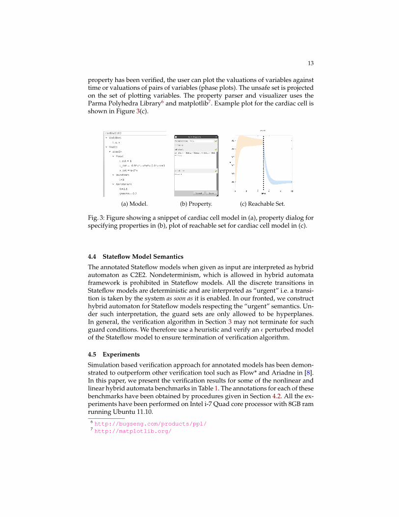
In this section, we discuss the C2E2 interface for handling verification, prop-erties and visualization. The users can add, edit, copy, delete or verify severalproperties. As each property is edited, the smart parser provides real-time feed-back about syntax errors and unbounded initial sets (Figure 3(b)). Once prop-erties are edited the verifier can be launched. Visual representation of reachablestates and locations can aid debugging process. To this end, we have integrateda visualizer into C2E2 for plotting the projections of the reachable states. Once a
13
property has been verified, the user can plot the valuations of variables againsttime or valuations of pairs of variables (phase plots). The unsafe set is projectedon the set of plotting variables. The property parser and visualizer uses theParma Polyhedra Library6 and matplotlib7. Example plot for the cardiac cell isshown in Figure 3(c).
(a) Model. (b) Property. (c) Reachable Set.
Fig. 3: Figure showing a snippet of cardiac cell model in (a), property dialog forspecifying properties in (b), plot of reachable set for cardiac cell model in (c).
4.4 Stateflow Model Semantics
The annotated Stateflow models when given as input are interpreted as hybridautomaton as C2E2. Nondeterminism, which is allowed in hybrid automataframework is prohibited in Stateflow models. All the discrete transitions inStateflow models are deterministic and are interpreted as “urgent” i.e. a transi-tion is taken by the system as soon as it is enabled. In our fronted, we constructhybrid automaton for Stateflow models respecting the “urgent” semantics. Un-der such interpretation, the guard sets are only allowed to be hyperplanes.In general, the verification algorithm in Section 3 may not terminate for suchguard conditions. We therefore use a heuristic and verify an ε perturbed modelof the Stateflow model to ensure termination of verification algorithm.
4.5 Experiments
Simulation based verification approach for annotated models has been demon-strated to outperform other verification tool such as Flow* and Ariadne in [8].In this paper, we present the verification results for some of the nonlinear andlinear hybrid automata benchmarks in Table 1. The annotations for each of thesebenchmarks have been obtained by procedures given in Section 4.2. All the ex-periments have been performed on Intel i-7 Quad core processor with 8GB ramrunning Ubuntu 11.10.
Navigation Benchmark 4 4 2.0 4.74 unsafeTable 1: Experimental Results for benchmark examples. Vars: Number of Vari-ables, Num. Loc. : Number of discrete locations in hybrid automata, TH: TimeHorizon for Verification, VT (sec) : Verification time for C2E2 in seconds, Result:Verification result of C2E2.
This early termination strategy for unsafe behavior of the system (Algo-rithm 1, line 11) when the system is unsafe is reflected in Table 1. On stan-dard examples C2E2 can successfully verify these systems within the order ofminutes and also handle nonlinear differential equations with trigonometricfunctions of inverted pendulum.
5 Conclusions and Future Work
C2E2 presented in this paper is a tool for verifying a broad class of hybridand dynamical systems models. It uses validated simulations and model an-notations to prove the most commonly encountered type of properties, namelybounded-time invariants. It can handle models created using the Stateflow en-vironment that is the de facto standard in embedded control design and imple-mentation. The improvements presented in this paper beyond the version of [8],include the complete support for hybrid models implemented in a new algo-rithm and the supporting theory, the new user interface for editing properties,and the reachtube plotting function. The tool is freely available for academicand research use from https://publish.illinois.edu/c2e2-tool/.
Our future plans include implementation of features to support temporalprecedence properties [9] and compositional reasoning [10,4]. Another avenueof work leverages the “embarrassing parallelism” in the simulation-based ap-proach. We anticipate that the C2E2’s architecture and its open interfaces, forexample, the .hyxml input format, text-based representation of reachtubes, willsupport research and eduction in embedded and hybrid systems community byhelping explore new ideas in modeling, verification, synthesis, and and testing.
Acknowledgements: The authors were supported by the National ScienceFoundation research grant CSR 1016791.
1. Computer assisted proofs in dynamic groups (capd).http://capd.ii.uj.edu.pl/index.php.
2. E. Asarin, T. Dang, and O. Maler. The d/dt tool for verification of hybrid systems.In Computer Aided Verification, pages 365–370. Springer, 2002.
3. A. Balluchi, A. Casagrande, P. Collins, A. Ferrari, T. Villa, and A. Sangiovanni-Vincentelli. Ariadne: a framework for reachability analysis of hybrid automata. InM.T.N.S., 2006.
4. A. Biere and R. Bloem, editors. Computer Aided Verification - 26th International Con-ference, CAV 2014, Held as Part of the Vienna Summer of Logic, VSL 2014, Vienna, Aus-tria, July 18-22, 2014. Proceedings, volume 8559 of Lecture Notes in Computer Science.Springer, 2014.
5. X. Chen, E. Abraham, and S. Sankaranarayanan. Flow*: An analyzer for non-linearhybrid systems. In Computer Aided Verification, pages 258–263. Springer, 2013.
6. Y. Deng, A. Rajhans, and A. A. Julius. Strong: A trajectory-based verification toolboxfor hybrid systems. In QEST, pages 165–168, 2013.
7. A. Donze. Breach, a toolbox for verification and parameter synthesis of hybrid sys-tems. In C.A.V. 2010.
8. P. S. Duggirala, S. Mitra, and M. Viswanathan. Verification of annotated modelsfrom executions. In EMSOFT, 2013.
9. P. S. Duggirala, L. Wang, S. Mitra, M. Viswanathan, and C. Munoz. Temporal prece-dence checking for switched models and its application to a parallel landing proto-col. In FM 2014: Formal Methods - 19th International Symposium, Singapore, May 12-16,2014. Proceedings, pages 215–229, 2014.
10. M. Franzle and J. Lygeros, editors. 17th International Conference on Hybrid Systems:Computation and Control (part of CPS Week), HSCC’14, Berlin, Germany, April 15-17,2014. ACM, 2014.
11. G. Frehse, C. Le Guernic, A. Donze, S. Cotton, R. Ray, O. Lebeltel, R. Ripado, A. Gi-rard, T. Dang, and O. Maler. Spaceex: Scalable verification of hybrid systems. InComputer Aided Verification, pages 379–395. Springer, 2011.
12. T. A. Henzinger, P.-H. Ho, and H. Wong-Toi. Hytech: A model checker for hybridsystems. In Computer aided verification, pages 460–463. Springer, 1997.
13. D. K. Kaynar, N. Lynch, R. Segala, and F. Vaandrager. The Theory of Timed I/O Au-tomata. Synthesis Lectures on Computer Science. Morgan Claypool, November 2005.Also available as Technical Report MIT-LCS-TR-917.
14. K. G. Larsen, P. Pettersson, and W. Yi. Uppaal in a nutshell. International Journal onSoftware Tools for Technology Transfer (STTT), 1(1):134–152, 1997.
15. W. Lohmiller and J. J. E. Slotine. On contraction analysis for non-linear systems.Automatica, 1998.
16. K. Manamcheri, S. Mitra, S. Bak, and M. Caccamo. A step towards verification andsynthesis from simulink/stateflow models. In H.S.C.C, 2011.
17. N. Nedialkov. Vnode-lp: Validated solutions for initial value problem for odes. Tech-nical report, 2006.
18. T. Nghiem, S. Sankaranarayanan, G. Fainekos, F. Ivancic, A. Gupta, and G. Pappas.Monte-carlo techniques for falsification of temporal properties of non-linear hybridsystems. In H.S.C.C, 2010.
19. L. Zou, N. Zhan, S. Wang, M. Franzle, and S. Qin. Verifying simulink diagrams viaa hybrid hoare logic prover. In EMSOFT, 2013.