Homework Solutions Problems from Engineering Mechanics - Statics, Meriam and Kraige 4th Edition Chapter 3 Problem 1 Page 126 The 50-kg homogenous smooth sphere rests on the 30 o incline and bears against the smooth vertical wall B. Calculate the contact forces at A and B. 1. Mechanical System = Sphere. The sphere is the appropriate mechanical system because the only force you know (weight) acts on the sphere and the two forces you want to know (contact forces) also act on the sphere. 2. Free Body Diagram = As smooth walls provide no resistance to movement along the wall, the only force they can exert is normal or perpendicular to the wall. Thus the free body diagram contains three forces, the weight of the ball and two normal contact forces at A and B. 3. Equations = Sum of Forces = Weight (downward) + Contact at B(horizontal) + Contact at A (diagonally upward). Note that as the directions of the forces at A and B are known but their magnitudes are unknown, we express these forces in terms of symbols representing their magnitude multiplied by unit vectors representing their direction. S F = -50 kg * 9.81 m/s 2 j - B i + A ( cos 60 i + sin 60 j) = ( 1/2 A - B) i + ( 3 1/2 /2 A - 490.5 N) j = 0 = 0 i + 0 j 4. Solve the Equations. For two vectors to be equal, each of their components must be equal. Thus each of the two components of the resultant force vector must be zero. Noting that the Y component involves only the unknown A, we can readily solve for A.
Transcript
EGR 181 Fall Quarter 1997Homework SolutionsProblems from Engineering Mechanics - Statics, Meriam and Kraige 4th Edition
Chapter 3 Problem 1 Page 126
The 50-kg homogenous smooth sphere restson the 30o incline and bears against thesmooth vertical wall B. Calculate the contactforces at A and B.
1. Mechanical System = Sphere. The sphere isthe appropriate mechanical system because theonly force you know (weight) acts on thesphere and the two forces you want to know(contact forces) also act on the sphere.
2. Free Body Diagram = As smooth walls provide noresistance to movement along the wall, the only forcethey can exert is normal or perpendicular to the wall. Thus the free body diagram contains three forces, theweight of the ball and two normal contact forces at Aand B.
3. Equations = Sum of Forces = Weight (downward) +Contact at B(horizontal) + Contact at A (diagonallyupward). Note that as the directions of the forces at Aand B are known but their magnitudes are unknown,we express these forces in terms of symbolsrepresenting their magnitude multiplied by unitvectors representing their direction.
S F = -50 kg * 9.81 m/s2 j - B i + A ( cos 60 i + sin 60j)
= ( 1/2 A - B) i + ( 31/2/2 A - 490.5 N) j = 0 = 0 i + 0 j
4. Solve the Equations. For two vectors to be equal, each of their components must be equal. Thuseach of the two components of the resultant force vector must be zero. Noting that the Y componentinvolves only the unknown A, we can readily solve for A.
EGR 181 Fall Quarter 1997Homework SolutionsProblems from Engineering Mechanics - Statics, Meriam and Kraige 4th Edition
Chapter 3 Problem 13 Page 129
Calculate the magnitude F of the forcesupported by the pin at A for the loadedbracket. Neglect the weight of thebracket.
1. Mechanical System = Bracket. Thebracket is the appropriate mechanicalsystem as the only force we know (900 N)acts on the bracket and the forces we wantto know (at pin A) act on the bracket.
2. Free Body Diagram. 900 N forceapplied diagonally downward. Weight ofthe bracket is neglected so no weight forceis shown. Contact at B with a smoothroller. The only resistance is to horizontalmovement, so we have only a horizontalforce. The pin at A resists both horizontaland vertical movement so we have both ahorizontal and a vertical component offorce at A. Pin A does permit the bracketto rotate or swing freely so there is nocouple at that point. Note that we havedepicted the forces exerted by the pin A onthe bracket. By the law of action andreaction these forces are equal andopposite to the forces exerted by thebracket on the pin. Thus in finding themagnitude of the force exerted by the pin
on the bracket, we are also finding the magnitude of the force exerted on the pin by the bracket.
3. Sum of the Forces = 900 N diagonally downward. Horizontal force of unknown magnitude at B. Force at A with unknown horizontal and vertical components. Note that all unknown values havebeen represented by appropriate symbols in the free body diagram.
S F = 900 N ( -sin(15) i - cos(15) j ) + B i + AX i + AY j = ( B + AX - 232.9 N ) i + ( AY - 869.3 N) j = 0 = 0 i + 0 j Noting that the force equation contains three unknown quantities but only two components indicatesthat an additional equation will be required. Thus we must also evaluate the sum of the moments. Wecan choose to sum moments about any point. We normally choose a point that will make the momentevaluation as simple as possible. If we sum moments about the pin at A, then the position vector tothe pin forces at A from that point will be zero, and their contribution to the moment will be zero. This appears to be a good choice of points. The position vector of the force at B from point A can beseen to be 0.23 m straight down. The position vector from point A to the 900 N force can be seen tobe 0.23 m straight down and 0.18 m to the right.
S MA = 0 X ( AX i + AY j ) + -0.23m j X B i + (-0.23m j + 0.18 m i) X (900 N ( -sin(15) i - cos(15) j) )
Recalling that i X i is zero, i X j is k, j X i is -k and j X j is zero, and performing the required crossproducts yields:
S MA = 0.23 m B k - 0.23 m 900 N sin(15) k - 0.18 m 900 N cos(15) k = ( 0.23 m B - 53.6 N m - 156.5 N m ) k = 0.23 m B - 210.1 N m ) k = 0 = 0 k
4. Solving the Equations. If two vectors are equal, their components must be equal. Thus the X andY components of the resultant force vector must be zero. The Z component of the resultant momentabout point A must be zero. Setting the Y component of the resultant force vector to zero determinesthe Y component of the pin force, AY.
AY = 869. 3 N
Setting the Z component of the moment equation to zero, determines the force exerted on the bracketat B, B.
B = 210.1 N m / 0.23 m = 913.3 N
Setting the X component of the resultant force to zero and using the value of the force B justdetermined, yields:
The fact that the result for AX is negative means that the force exerted on the bracket by the pin in thehorizontal direction is in the opposite direction from that shown on the free body diagram. Thus theforce exerted on the bracket by the pin is vertically upward (as shown) and horizontally to the left(opposite of shown). The total force exerted by the pin on the bracket is :
A = AX i + AY j = -680.3 N i + 869.3 N j
The magnitude of this force, which is also the magnitude of the force exerted by the bracket on thepin, is given by the square root of the sum of the squares of the components.
EGR 181 Fall Quarter 1997Homework SolutionsProblems from Engineering Mechanics - Statics, Meriam and Kraige 4th Edition
Chapter 3 Problem 15 Page 129
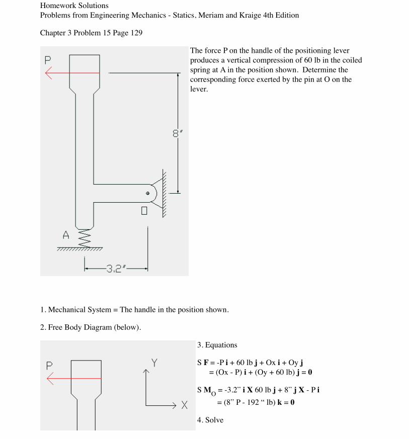
The force P on the handle of the positioning leverproduces a vertical compression of 60 lb in the coiledspring at A in the position shown. Determine thecorresponding force exerted by the pin at O on thelever.
1. Mechanical System = The handle in the position shown.
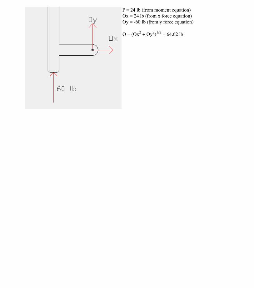
2. Free Body Diagram (below).
3. Equations
S F = -P i + 60 lb j + Ox i + Oy j = (Ox - P) i + (Oy + 60 lb) j = 0
S MO = -3.2” i X 60 lb j + 8” j X - P i = (8” P - 192 “ lb) k = 0
EGR 181 Fall Quarter 1997Homework SolutionsProblems from Engineering Mechanics - Statics, Meriam and Kraige 4th Edition
Chapter 3 Problem 18 Page 130
The indicated location(G) of the center ofgravity of the 3600-lbpickup truck is for theunladen condition. If aload whose center ofgravity is x = 16 in.behind the rear axle isadded to the truck,determine the loadweight WL for which thenormal forces under thefront and rear wheels are
equal.
1. Mechanical System = Truck, loaded such that normal forces under front and rear wheels are equal.
2. Free Body Diagram below.
3. Equations:
S F = N j - 3600 lb j + N j- WL j = (2 N -3600 lb - WL)j = 0
S MW = -128” i X N j +-83” i X -3600 lb j + -16”i X N j = (298800 “lb -144” N) k = 0
EGR 181 Fall Quarter 1997Homework SolutionsProblems from Engineering Mechanics - Statics, Meriam and Kraige 4th Edition
Chapter 3 Problem 37 Page 135
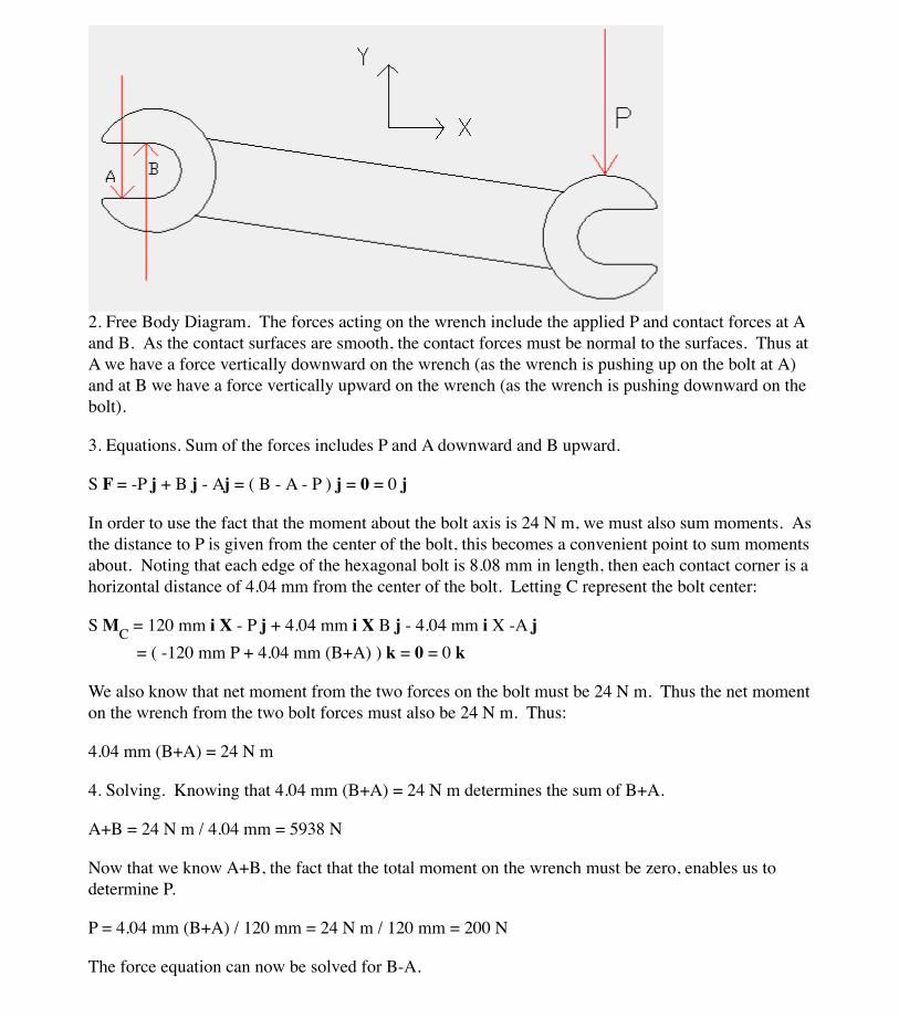
A torque (moment) of 24 N m is required to turn the bolt about its axis. Determine P and the forcesbeween the smooth hardened jaws of the wrench and the corners of A and B of the hexagonal head. Assume that the wrench fits easily on the bolt so that contact is made at corners A and B only.
1. Mechanical System = Wrench. The forces of interestall act on the wrench. The information known is themoment on the bolt produced by the wrench. By the lawof action and reaction, this must be the same moment(opposite direction) produced by the bolt on the wrench. Note that as the bolt is hexagonal and spans a verticaldistance of 14 mm, each side of the bolt must be of length(14 mm/2)/cos(30) or 8.08 mm (see figure of triangleshowing half height of bolt and side length L).
2. Free Body Diagram. The forces acting on the wrench include the applied P and contact forces at Aand B. As the contact surfaces are smooth, the contact forces must be normal to the surfaces. Thus atA we have a force vertically downward on the wrench (as the wrench is pushing up on the bolt at A)and at B we have a force vertically upward on the wrench (as the wrench is pushing downward on thebolt).
3. Equations. Sum of the forces includes P and A downward and B upward.
S F = -P j + B j - Aj = ( B - A - P ) j = 0 = 0 j
In order to use the fact that the moment about the bolt axis is 24 N m, we must also sum moments. Asthe distance to P is given from the center of the bolt, this becomes a convenient point to sum momentsabout. Noting that each edge of the hexagonal bolt is 8.08 mm in length, then each contact corner is ahorizontal distance of 4.04 mm from the center of the bolt. Letting C represent the bolt center:
S MC = 120 mm i X - P j + 4.04 mm i X B j - 4.04 mm i X -A j = ( -120 mm P + 4.04 mm (B+A) ) k = 0 = 0 k
We also know that net moment from the two forces on the bolt must be 24 N m. Thus the net momenton the wrench from the two bolt forces must also be 24 N m. Thus:
4.04 mm (B+A) = 24 N m
4. Solving. Knowing that 4.04 mm (B+A) = 24 N m determines the sum of B+A.
A+B = 24 N m / 4.04 mm = 5938 N
Now that we know A+B, the fact that the total moment on the wrench must be zero, enables us todetermine P.
P = 4.04 mm (B+A) / 120 mm = 24 N m / 120 mm = 200 N
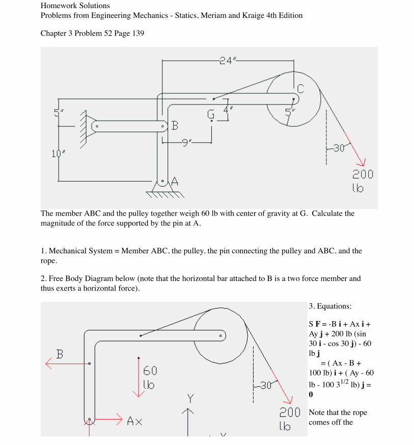
pulley on a tangentmaking an angle of30 degrees with thevertical, hence the
contact point on the pulley makes an angle of 30 degrees with the horizontal.
S MA = 10” j X -B i + (9” i X -60 lb j) + {(24”+5”cos 30)i + (15” + 5”sin 30)j} X 200 lb (sin 30 i -cos 30 j) = (10” B - 540 in lb - 6656.9 in lb) k = 0
4. Solve:
B = 719.7 lb ( from moment equation)Ax = 619.7 lb ( from x force equation)Ay = 233.2 lb (from y force equation)
EGR 181 Fall Quarter 1997Homework SolutionsProblems from Engineering Mechanics - Statics, Meriam and Kraige 4th Edition
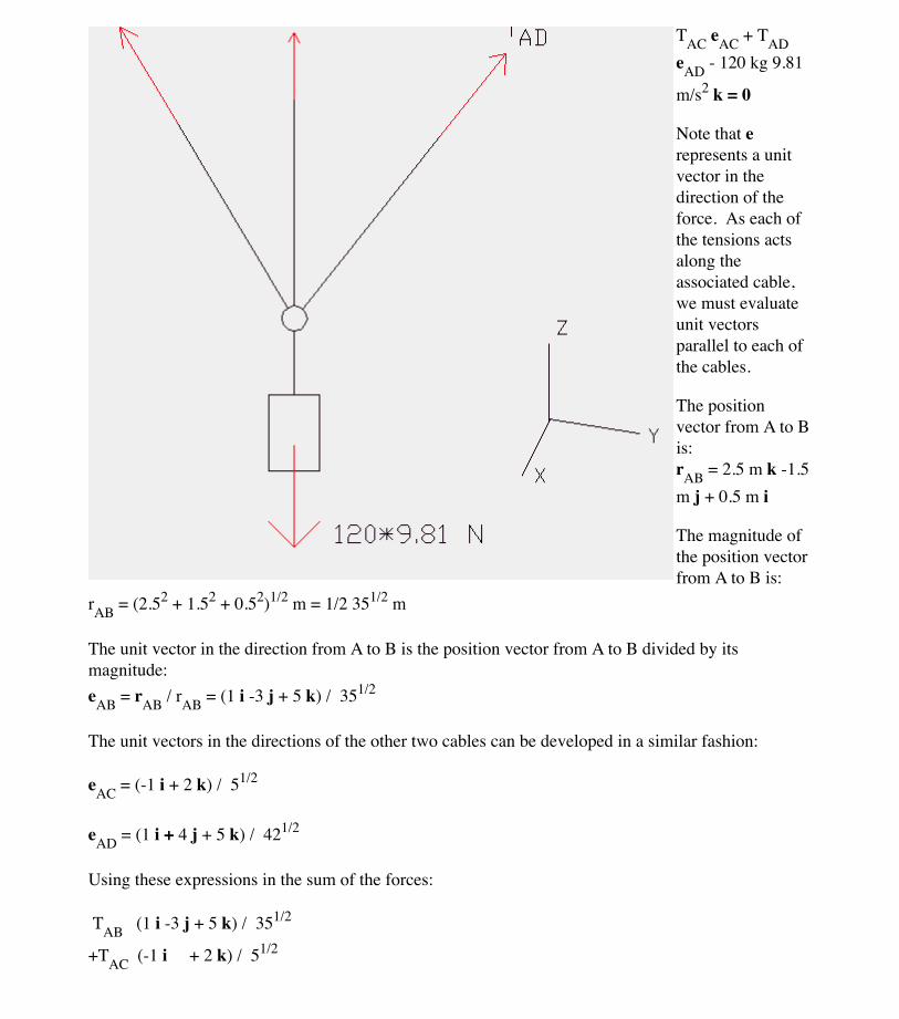
Chapter 3 Problem 61 Page 150
The threecables,AB, AC,and CDsupportthe 120kg mass. The three
dimensional locations of the points A, B, C, and D are given in the figure. Note that Z is verticallyupward, Y is from left to right, while X is from back to front. Determine the tension in cables AB,AC, and AD.
1. Mechanical System = 120 kg mass, ring, and parts of supporting cables.
Note that erepresents a unitvector in thedirection of theforce. As each ofthe tensions actsalong theassociated cable,we must evaluateunit vectorsparallel to each ofthe cables.
The positionvector from A to Bis:rAB = 2.5 m k -1.5m j + 0.5 m i
The magnitude ofthe position vectorfrom A to B is:
rAB = (2.52 + 1.52 + 0.52)1/2 m = 1/2 351/2 m
The unit vector in the direction from A to B is the position vector from A to B divided by itsmagnitude:eAB = rAB / rAB = (1 i -3 j + 5 k) / 351/2
The unit vectors in the directions of the other two cables can be developed in a similar fashion:
EGR 181 Fall Quarter 1997Homework SolutionsProblems from Engineering Mechanics - Statics, Meriam and Kraige 4th Edition
Chapter 3 Problem 77 Page 155
The uniform panel doorshown in the isometricdrawing weighs 60 lb and isprevented from opening bythe strut C, which is a lighttwo-force member whoseupper end is secured underthe door knob and whoselower end is attached to arubber cup which does notslip on the floor. Of the doorhinges A and B, only B cansupport force in the verticalz-direction. Calcuate thecompression in the strut andthe horizontal components ofthe forces supported by thehinges A and B when ahorizontal force P = 50 lb isapplied normal to the plane ofthe door as shown.
Noting that the force in the strut isparallel to the vector (0,-30”, 40”), weobtain the following unit vector for thestrut force:
eC = -3/5 j + 4/5 k
S F = 50 lb j -60 lb k + C (-3/5 j + 4/5 k )+ Bx i + By j + Bz k + Ax i + Ay j = (Ax + Bx) i + ( 50 lb -3/5 C + Ay +By) j + (4/5 C - 60 lb + Bz) k = 0
Note that as the door is uniform, its masscenter is located at its geometric center. Thus it is 24” along the X axis from thehinges and 40” above the floor (along theZ axis). Summing moments about thehinge at B to eliminate the threecomponents of B yields:
S MB = 64” k X ( Ax i + Ay j ) + 24” i X-60 lb k + ( 48” i + 72” k) X 50 lb j + (40” i + 32” k ) X C( -3/5 j + 4/5 k) = ( 96/5” C-3600 in lb -64”Ay ) i + ( 64”Ax + 1440 in lb -32” C ) j + ( 2400 in lb -24” C) k = 0
4. Solve:
C = 100 lb ( z moment equation)Ax = 27.5 lb ( y moment equation)Ay = -26.25 lb ( x moment equation)Bx = -27. 5 lb ( x force equation)By = 36.25 lb ( y force equation)Bz = -20 lb ( z force equation)
EGR 181 Fall Quarter 1997Homework SolutionsProblems from Engineering Mechanics - Statics, Meriam and Kraige 4th Edition
Chapter 3 Problem 96 Page 165
The pin at O can support amaximum force of 3.5 kN. What is the correspondingmaximum load L which canbe applied to the angledbracket AOB? Note that thebracket consists of a singlerigid body composed of twoarms. One arm is horizontaland of length 350 mm. Theother arm makes an angle of60 degrees with the horizontaland has a length of 250 mm. The load is applied verticallyto the end of the horizontalarm. The bracket issupported by a frictionless pinat O. The pin at O is at the
connection point between the two arms. The bracket is prevented from rotating by a roller support atthe end of the arm angled at 60 degrees.
1. Mechanical System = Angle bracket, AOB
2. Free Body Diagram below. Note that as a roller force is perpendicular to the supporting surface,roller force B is perpendicular to a line that makes an angle of 60 degrees with the horizontal. Thusthe roller force B must make an angle of 30 degrees with the horizontal.
3. Equations:
S F = -L j + Ox i + Oy j + B ( cos 30i - sin 30 j) = ( Ox + B cos 30 ) i + ( Oy - L -B sin 30) j = 0
S MO = -0.35 m i X -L j + .25 m ( sin30 i + cos 30 j ) X B ( cos 30 i - sin30 j) = ( 0.35 m L - 0.25 m B ) k = 0
EGR 181 Fall Quarter 1997Homework SolutionsProblems from Engineering Mechanics - Statics, Meriam and Kraige 4th Edition
Chapter 3 Problem 98 Page 165
A 50-kg acrobat pedals her unicycle across the taut but slightly elastic cable. If the deflection at the center ofthe 18-m span is 75 mm, determine the tension in the cable. Neglect the effects of the weights of the cableand the unicycle. Note that the deflection of the cable and the acrobat have not been drawn to scale.
1. Mechanical System = acrobat, unicycle, and part of cable supporting the acrobat.
2. Free Body Diagram below.
3. Equations:
S F = TL (-cos q i + sin q j) - 50*9.81 N j + TR (cos q i + sin q j) = cos q (TR - TL) i + { sin q (TR + TL) - 490.5 N } j = 0
tan q = 0.075/9 sin q = 0.075/(92 + 0.0752)1/2 cos q = 9/(92 + 0.0752)1/2
4. Solve
TR = TL (x force equation)
TR = TL = 490.5 N / 2 /sin q = 29430 N ( y force equation)
EGR 181 Fall Quarter 1997Homework SolutionsProblems from Engineering Mechanics - Statics, Meriam and Kraige 4th Edition
Chapter 3 Problem 100 Page 166
The pulley bracket is secured to its foundation by two bolts B and two bolts C with an initial tensionin each of the four bolts prior to application of the 500-N tension in the cable. Determine the increaseDT in tension in each of the bolts C and the increase DF in force under each side of the bracket at Bresulting from application of the cable tension. Assume that the bolt holes are oversized with allhorizontal force supported by the small ledge at A. Also assume that the vertical reactions on the baseare concentrated at the center lines of the bolts. These assumptions would be typical designconsiderations. The following figure shows both a top view and a side view of the bracket. Neitherview shows the supporting ledge at A or the floor to which the bracket is bolted. From the top viewyou can see the tops of the four bolts, however the pulley cable is not shown in the top view. The sideview shows the pulley bracket, side views of the bolts, the pulley, and the forces from the pulleycable. The side view does not show the floor or the supporting ledge at A. The side view shows all ofthe relevant dimensions. The pulley radius is not given but will be shown to be irrelevant.
2. Free Body Diagram below. Side view. Note that only the changes in forces are shown as thesechanges must also satisfy the equilibrium conditions. Note the factors of 2 to account for the twobolts at each position.
3. Equations:
S F = -2 DT j + 2 DF j - A i + 500 N i + 500 N (cos 45 i - sin 45 j ) = ( 500 N + 250 21/2 N - A ) i + (2 DF - 2 DT - 250 21/2 N) j = 0
S MB = -0.2 m i X -2 DT j + { 0.1 m i + (0.12 m + R) j } X 500 N i + {(0.1m - R/21/2)i + (0.12 m -
R/21/2)j } X { 250 21/2 N i - 250 21/2 N j } = { 0.4 m DT - 60 N m - 55 21/2 Nm } k = 0
R is the radius of the pulley and drops out of the final expression for the moment sum.
4. Solve: DT = 344.5 N ( z moment equation)DF = 521.2 N (y force equation)
EGR 181 Fall Quarter 1997Homework SolutionsProblems from Engineering Mechanics - Statics, Meriam and Kraige 4th Edition
Chapter 3 Problem 103 Page 167
A vertical force P on the foot pedal of the bell crank is required to produce a tension T of 400 N in thevertical control rod. Determine the corresponding bearing reactions at the support points A and B.The bell crank is shown below in light blue and yellow. Some of the relevant points are labeled inblue. A suggested set of axes are shown in purple. The origin of those axes is at the point C. Theforces P and T are shown in red. These forces act vertically downward (-Z). The force P is applied ata point F which is 200 mm down the -Y axis from C. The point D is distance of 120 mm from C andlies along a line in the YZ plane. This line makes an angle of 30 degrees with the positive Y axis. Thus the Y coordinate of point D is 120 mm * cos(30) while the Z coordinate of D is 120 mm *sin(30). The control rod force passes through point E which is a distance of 60 mm along the positiveX axis from the point D. The two supports at A and B are also shown in light blue. The supportpoints at A and B are each 100 mm from C. The vector from C to A points in the -X direction, whilethe vector from C to B points in the +X direction.
1. Mechanical System = Bell Crank.
2. Free Body Diagram below. Note that from the figure in the text it would appear that the bearing atB cannot support any force along the x axis.
S F = -P k - 400 N k + Ax i + Ay j + Az k + By j + Bz k = Ax i + (Ay + By) j + (Az + Bz - P - 400 N) k = 0
S MA = (0.1 m i - 0.2 m j ) X -P k + 0.2 m i X ( By j + Bz k ) + { 0.16 m i + 0.12 m(cos 30 j + sin 30k) } X -400 N k = (0.2 m P - 24 31/2 Nm) i + ( 0.1 m P - 0.2m Bz + 64 Nm ) j + (0.2 m By ) k = 0
4. Solve:
By = 0 ( z moment equation)P = 207.8 N ( x moment equation)Bz = 423.9 N ( y moment equation)Ax = 0 ( x force equation)Ay = 0 ( y force equation)Az = 183.9 N ( z force equation)
Determine the magnitudes of the forces C and T, which, along with theother three forces shown, act on the bridge-truss joint.
Solution. The given sketch constitutes the free-body diagram of the isolatedsection of the joint in question and shows the five forces which are in equilibrium.
Solution 1 (scalar algebra). For the x-y axes as shown we have
(a)
(b)
Simultaneous solution of Eqs. (a) and (b) produces
Ans.
Solution II (scalar algebra). To avoid a simultaneous solution, we may use axesx�-y� with the first summation in the y�-direction to eliminate reference to T. Thus,
Ans.
Ans.
Solution III (vector algebra). With unit vectors i and j in the x- and y-direc-tions, the zero summation of forces for equilibrium yields the vector equation
Equating the coefficients of the i- and j-terms to zero gives
which are the same, of course, as Eqs. (a) and (b), which we solved above.
Solution IV (geometric). The polygon representing the zero vector sum ofthe five forces is shown. Equations (a) and (b) are seen immediately to give theprojections of the vectors onto the x- and y-directions. Similarly, projections ontothe x�- and y�-directions give the alternative equations in Solution II.
A graphical solution is easily obtained. The known vectors are laid off head-to-tail to some convenient scale, and the directions of T and C are then drawn toclose the polygon. The resulting intersection at point P completes the solution,thus enabling us to measure the magnitudes of T and C directly from the draw-ing to whatever degree of accuracy we incorporate in the construction.
T sin 40� � 3 � C cos 20� � 0
8 � T cos 40� � C sin 20� � 16 � 0
� (C cos 20�)j � 16i � 0
8i � (T cos 40�)i � (T sin 40�)j � 3j � (C sin 20�)i[ΣF � 0]
T � 9.09 kN
T � 8 cos 40� � 16 cos 40� � 3 sin 40� � 3.03 sin 20� � 0[ΣFx� � 0]
C � 3.03 kN
�C cos 20� � 3 cos 40� � 8 sin 40� � 16 sin 40� � 0[ΣFy� � 0]
T � 9.09 kN C � 3.03 kN
0.643T � 0.940C � 3
T sin 40� � C cos 20� � 3 � 0 [ΣFy � 0]
0.766T � 0.342C � 8
8 � T cos 40� � C sin 20� � 16 � 0 [ΣFx � 0]
Art ic le 3/3 Equi l ibr ium Condit ions 127
40°
20°
3 kN
8 kN
P
TC
16 kN
x′
T
x
y
y′
16 kN
3 kN
C
8 kN40°
20°
� The known vectors may be added inany order desired, but they must beadded before the unknown vectors.
Helpful Hints
� Since this is a problem of concur-rent forces, no moment equation isnecessary.
� The selection of reference axes to fa-cilitate computation is always an im-portant consideration. Alternativelyin this example we could take a setof axes along and normal to the di-rection of C and employ a force sum-mation normal to C to eliminate it.
�
�
�
c03.qxd 1/23/06 4:48 PM Page 127
Sample Problem 3/2
Calculate the tension T in the cable which supports the 1000-lb load withthe pulley arrangement shown. Each pulley is free to rotate about its bearing,and the weights of all parts are small compared with the load. Find the magni-tude of the total force on the bearing of pulley C.
Solution. The free-body diagram of each pulley is drawn in its relative posi-tion to the others. We begin with pulley A, which includes the only known force.With the unspecified pulley radius designated by r, the equilibrium of momentsabout its center O and the equilibrium of forces in the vertical direction require
From the example of pulley A we may write the equilibrium of forces on pulley Bby inspection as
For pulley C the angle � � 30� in no way affects the moment of T about the cen-ter of the pulley, so that moment equilibrium requires
Ans.
Equilibrium of the pulley in the x- and y-directions requires
Ans.
Sample Problem 3/3
The uniform 100-kg I-beam is supported initially by its end rollers on thehorizontal surface at A and B. By means of the cable at C it is desired to elevateend B to a position 3 m above end A. Determine the required tension P, the reac-tion at A, and the angle � made by the beam with the horizontal in the elevatedposition.
Solution. In constructing the free-body diagram, we note that the reaction onthe roller at A and the weight are vertical forces. Consequently, in the absence ofother horizontal forces, P must also be vertical. From Sample Problem 3/2 wesee immediately that the tension P in the cable equals the tension P applied tothe beam at C.
Moment equilibrium about A eliminates force R and gives
Ans.
Equilibrium of vertical forces requires
Ans.
The angle � depends only on the specified geometry and is
� Clearly the equilibrium of this paral-lel force system is independent of �.
Helpful Hint
� Clearly the radius r does not influencethe results. Once we have analyzed asimple pulley, the results should beperfectly clear by inspection.
�
�
c03.qxd 1/23/06 4:48 PM Page 128
Sample Problem 3/4
Determine the magnitude T of the tension in the supporting cable and themagnitude of the force on the pin at A for the jib crane shown. The beam AB is astandard 0.5-m I-beam with a mass of 95 kg per meter of length.
Algebraic solution. The system is symmetrical about the vertical x-y planethrough the center of the beam, so the problem may be analyzed as the equilib-rium of a coplanar force system. The free-body diagram of the beam is shown inthe figure with the pin reaction at A represented in terms of its two rectangularcomponents. The weight of the beam is 95(10�3)(5)9.81 � 4.66 kN and actsthrough its center. Note that there are three unknowns Ax, Ay, and T, which maybe found from the three equations of equilibrium. We begin with a momentequation about A, which eliminates two of the three unknowns from the equa-tion. In applying the moment equation about A, it is simpler to consider the mo-ments of the x- and y-components of T than it is to compute the perpendiculardistance from T to A. Hence, with the counterclockwise sense as positive wewrite
from which Ans.
Equating the sums of forces in the x- and y-directions to zero gives
Ans.
Graphical solution. The principle that three forces in equilibrium must beconcurrent is utilized for a graphical solution by combining the two known verti-cal forces of 4.66 and 10 kN into a single 14.66-kN force, located as shown on themodified free-body diagram of the beam in the lower figure. The position of thisresultant load may easily be determined graphically or algebraically. The inter-section of the 14.66-kN force with the line of action of the unknown tension Tdefines the point of concurrency O through which the pin reaction A must pass.The unknown magnitudes of T and A may now be found by adding the forceshead-to-tail to form the closed equilibrium polygon of forces, thus satisfyingtheir zero vector sum. After the known vertical load is laid off to a convenientscale, as shown in the lower part of the figure, a line representing the given di-rection of the tension T is drawn through the tip of the 14.66-kN vector. Like-wise a line representing the direction of the pin reaction A, determined from theconcurrency established with the free-body diagram, is drawn through the tail ofthe 14.66-kN vector. The intersection of the lines representing vectors T and Aestablishes the magnitudes T and A necessary to make the vector sum of theforces equal to zero. These magnitudes are scaled from the diagram. The x- andy-components of A may be constructed on the force polygon if desired.
[A � �Ax
2 � Ay
2] A � �(17.77)2 � (6.37)2 � 18.88 kN
Ay � 19.61 sin 25� � 4.66 � 10 � 0 Ay � 6.37 kN[ΣFy � 0]
� The justification for this step isVarignon’s theorem, explained inArt. 2/4. Be prepared to take full ad-vantage of this principle frequently.
� The calculation of moments in two-dimensional problems is generallyhandled more simply by scalar alge-bra than by the vector cross product r F. In three dimensions, as we willsee later, the reverse is often the case.
� The direction of the force at A couldbe easily calculated if desired. How-ever, in designing the pin A or inchecking its strength, it is only themagnitude of the force that matters.
�
�
�
�
c03.qxd 1/23/06 4:48 PM Page 129
Sample Problem 3/5
The uniform 7-m steel shaft has a mass of 200 kg and is supported by a ball-and-socket joint at A in the horizontal floor. The ball end B rests against thesmooth vertical walls as shown. Compute the forces exerted by the walls and thefloor on the ends of the shaft.
Solution. The free-body diagram of the shaft is first drawn where the contactforces acting on the shaft at B are shown normal to the wall surfaces. In additionto the weight W � mg � 200(9.81) � 1962 N, the force exerted by the floor onthe ball joint at A is represented by its x-, y-, and z-components. These compo-nents are shown in their correct physical sense, as should be evident from the re-quirement that A be held in place. The vertical position of B is found from
, h � 3 m. Right-handed coordinate axes are assigned as shown.
Vector solution. We will use A as a moment center to eliminate reference tothe forces at A. The position vectors needed to compute the moments about A are
where the mass center G is located halfway between A and B.The vector moment equation gives
Equating the coefficients of i, j, and k to zero and solving give
Ans.
The forces at A are easily determined by
and
Finally
Ans.
Scalar solution. Evaluating the scalar moment equations about axes throughA parallel, respectively, to the x- and y-axes, gives
� We could, of course, assign all of theunknown components of force in thepositive mathematical sense, in whichcase Ax and Ay would turn out to benegative upon computation. The free-body diagram describes the physicalsituation, so it is generally preferableto show the forces in their correctphysical senses wherever possible.
� Note that the third equation �2By �
6Bx � 0 merely checks the results ofthe first two equations. This resultcould be anticipated from the factthat an equilibrium system of forcesconcurrent with a line requires onlytwo moment equations (Category 2under Categories of Equilibrium).
� We observe that a moment sumabout an axis through A parallel tothe z-axis merely gives us 6Bx �
2By � 0, which serves only as acheck as noted previously. Alterna-tively we could have first obtainedAz from and then taken our moment equations about axesthrough B to obtain A x and Ay.
ΣFz � 0
c03.qxd 1/23/06 4:48 PM Page 150
Sample Problem 3/6
A 200-N force is applied to the handle of the hoist in the direction shown.The bearing A supports the thrust (force in the direction of the shaft axis), whilebearing B supports only radial load (load normal to the shaft axis). Determinethe mass m which can be supported and the total radial force exerted on theshaft by each bearing. Assume neither bearing to be capable of supporting a mo-ment about a line normal to the shaft axis.
Solution. The system is clearly three-dimensional with no lines or planes ofsymmetry, and therefore the problem must be analyzed as a general space sys-tem of forces. A scalar solution is used here to illustrate this approach, althougha solution using vector notation would also be satisfactory. The free-body dia-gram of the shaft, lever, and drum considered a single body could be shown by aspace view if desired, but is represented here by its three orthogonal projections.
The 200-N force is resolved into its three components, and each of the threeviews shows two of these components. The correct directions of Ax and Bx may beseen by inspection by observing that the line of action of the resultant of the two70.7-N forces passes between A and B. The correct sense of the forces Ay and By
cannot be determined until the magnitudes of the moments are obtained, so theyare arbitrarily assigned. The x-y projection of the bearing forces is shown interms of the sums of the unknown x- and y-components. The addition of Az andthe weight W � mg completes the free-body diagrams. It should be noted thatthe three views represent three two-dimensional problems related by the corre-sponding components of the forces.
� If the standard three views of ortho-graphic projection are not entirelyfamiliar, then review and practicethem. Visualize the three views asthe images of the body projectedonto the front, top, and end surfacesof a clear plastic box placed over andaligned with the body.
� We could have started with the x-zprojection rather than with the x-yprojection.
� The y-z view could have followed im-mediately after the x-y view sincethe determination of Ay and By maybe made after m is found.
� Without the assumption of zero mo-ment supported by each bearingabout a line normal to the shaft axis,the problem would be statically in-determinate.
�
�
�
�
c03.qxd 1/23/06 4:48 PM Page 151
Sample Problem 3/7
The welded tubular frame is secured to the horizontal x-y plane by a ball-and-socket joint at A and receives support from the loose-fitting ring at B. Underthe action of the 2-kN load, rotation about a line from A to B is prevented by thecable CD, and the frame is stable in the position shown. Neglect the weight ofthe frame compared with the applied load and determine the tension T in thecable, the reaction at the ring, and the reaction components at A.
Solution. The system is clearly three-dimensional with no lines or planes ofsymmetry, and therefore the problem must be analyzed as a general space sys-tem of forces. The free-body diagram is drawn, where the ring reaction is shownin terms of its two components. All unknowns except T may be eliminated by amoment sum about the line AB. The direction of AB is specified by the unit
vector The moment of T about AB
is the component in the direction of AB of the vector moment about the point Aand equals Similarly the moment of the applied load F about AB is
With the vector expressions for T, F, r1, and r2 are
The moment equation now becomes
Completion of the vector operations gives
Ans.
and the components of T become
We may find the remaining unknowns by moment and force summations asfollows:
� The advantage of using vector nota-tion in this problem is the freedomto take moments directly about anyaxis. In this problem this freedompermits the choice of an axis thateliminates five of the unknowns.
� Recall that the vector r in the expres-sion r F for the moment of a forceis a vector from the moment center toany point on the line of action of theforce. Instead of r1, an equally simplechoice would be the vector .
� The negative signs associated withthe A-components indicate that theyare in the opposite direction to thoseshown on the free-body diagram.