Print: ISBN 0-7381-2522-9 SH94871PDF: ISBN 0-7381-2523-7 SS94871
No part of this publication may be reproduced in any form, in an electronic retrieval system or otherwise, without the priorwritten permission of the publisher.
IEEE Std C62.36-2000(Revision of
IEEE Std C62.36-1994)
IEEE Standard Test Methods forSurge Protectors Used in Low-Voltage Data, Communications,and Signaling Circuits
Sponsor
Surge Protective Devices Committeeof theIEEE Power Engineering Society
Approved 30 June 2000
IEEE-SA Standards Board
Abstract: Methods for testing and measuring the characteristics of surge protectors used in low-voltage data, communications, and signaling circuits with voltages less than or equal to 1000 V rmsor 1200 V dc are established. The surge protectors are designed to limit voltage surges, currentsurges, or both. The surge protectors covered are multiple-component series or parallel combina-tions of linear or nonlinear elements. Tests are included for characterizing standby performance,surge-limiting capabilities, and surge lifetime. Packaged single gas-tube, air-gap, varistor, or ava-lanche junction surge-protective devices are not covered, nor are test methods for low-voltagepower circuit applications.
Keywords: communications circuits, current limiters, data circuits, electrical protection, signalingcircuits, surge protectors, surge-protective devices, voltage limiters
IEEE Standards documents are developed within the IEEE Societies and the Standards Coordinating Com-mittees of the IEEE Standards Association (IEEE-SA) Standards Board. Members of the committees servevoluntarily and without compensation. They are not necessarily members of the Institute. The standardsdeveloped within IEEE represent a consensus of the broad expertise on the subject within the Institute aswell as those activities outside of IEEE that have expressed an interest in participating in the development ofthe standard.
Use of an IEEE Standard is wholly voluntary. The existence of an IEEE Standard does not imply that thereare no other ways to produce, test, measure, purchase, market, or provide other goods and services related tothe scope of the IEEE Standard. Furthermore, the viewpoint expressed at the time a standard is approved andissued is subject to change brought about through developments in the state of the art and commentsreceived from users of the standard. Every IEEE Standard is subjected to review at least every five years forrevision or reaffirmation. When a document is more than five years old and has not been reaffirmed, it is rea-sonable to conclude that its contents, although still of some value, do not wholly reflect the present state ofthe art. Users are cautioned to check to determine that they have the latest edition of any IEEE Standard.
Comments for revision of IEEE Standards are welcome from any interested party, regardless of membershipaffiliation with IEEE. Suggestions for changes in documents should be in the form of a proposed change oftext, together with appropriate supporting comments.
Interpretations: Occasionally questions may arise regarding the meaning of portions of standards as theyrelate to specific applications. When the need for interpretations is brought to the attention of IEEE, theInstitute will initiate action to prepare appropriate responses. Since IEEE Standards represent a consensus ofall concerned interests, it is important to ensure that any interpretation has also received the concurrence of abalance of interests. For this reason, IEEE and the members of its societies and Standards CoordinatingCommittees are not able to provide an instant response to interpretation requests except in those cases wherethe matter has previously received formal consideration.
Comments on standards and requests for interpretations should be addressed to:
IEEE is the sole entity that may authorize the use of certification marks, trademarks, or other designations toindicate compliance with the materials set forth herein.
Authorization to photocopy portions of any individual standard for internal or personal use is granted by theInstitute of Electrical and Electronics Engineers, Inc., provided that the appropriate fee is paid to CopyrightClearance Center. To arrange for payment of licensing fee, please contact Copyright Clearance Center, Cus-tomer Service, 222 Rosewood Drive, Danvers, MA 01923 USA; (978) 750-8400. Permission to photocopyportions of any individual standard for educational classroom use can also be obtained through the Copy-right Clearance Center.
Note: Attention is called to the possibility that implementation of this standard mayrequire use of subject matter covered by patent rights. By publication of this standard,no position is taken with respect to the existence or validity of any patent rights inconnection therewith. The IEEE shall not be responsible for identifying patents forwhich a license may be required by an IEEE standard or for conducting inquiries intothe legal validity or scope of those patents that are brought to its attention.
(This introduction is not a part of IEEE Std C62.36-2000, IEEE Standard Test Methods for Surge Protectors Used inLow-Voltage Data, Communications, and Signaling Circuits.)
This standard was developed to establish methods for testing characteristics and for identifying criteria thatdetermine the end-of-life for surge protectors used in low-voltage data, communications, and signaling cir-cuits. The surge protectors covered are multiple-component series or parallel combinations of linear or non-linear elements packaged for the purpose of limiting surge voltages, currents, or both.
Since these test methods and criteria apply to a range of surge protectors used in various environmental con-ditions, and include various combinations of elements, some tests are not appropriate for some surge protec-tors. Manufacturers and users may determine which tests apply to a surge protector intended for a specificapplication. These standard test methods should improve the consistency of information on data sheets forthe covered surge protectors.
The need for this standard arose because of the following industry trends:
a) The development and proliferation of surge protection devices that use solid-state components tolimit current or voltage
b) The manufacture and use of multiple-component surge protectors
c) The increasing use of sensitive electronic circuits that require protection if exposed to surges fromthe environment
This edition of the standard includes test methods for surge protectors intended for use on coaxial andtwinaxial circuits. The tests for insertion loss and return loss are modified to use network analyzers inhigh-frequency applications. A test has been added to measure the degree of coupling between ports of amultiport surge protector, and the ability of a surge protector to satisfy a pulse mask test. The tests foranalog and digital insertion loss have been combined into a single insertion loss test. The test levels andconfigurations for several of the impulse tests have been updated. Information has been included on gen-eral methods for test measurements.
Participants
At the time this standard was approved by the IEEE-SA Standards Board, the Low-Voltage Data, Communi-cations, and Signaling Circuits Working Group (3.6.7) had the following members who contributed to writ-ing this revision:
Michael Parente, ChairWilliam Curry, Secretary
Nisar ChaudhryChrysanthos ChrysanthouErnest J. Gallo
Phillip JonesWilhelm H. KappMark LynnesAlbert R. Martin
The following members of the balloting committee voted on this standard:
When the IEEE-SA Standards Board approved this standard on 30 June 2000, it had the followingmembership:
Donald N. Heirman, ChairJames T. Carlo, Vice ChairJudith Gorman, Secretary
*Member Emeritus
Also included is the following nonvoting IEEE-SA Standards Board liaison:
Alan Cookson, NIST RepresentativeDonald R. Volzka, TAB Representative
Yvette Ho SangIEEE Standards Project Editor
Charles L. BallentineRickard BentingerJohn S. BonnesenJames CaseJames F. ChristensenBryan R. ColeWilliam CurryJames FunkeErnest J. GalloPeter A. GoodwinWillliam Greason
David W. JacksonWilhelm H. KappJoseph L. KoepfingerGerald E. LeeCarl E. LindquistWilliam A. MaguireDaleep C. MohlaHans-Wolfgang OertelJoseph C. OsterhoutMichael Parente
Carlos O. PeixotoPercy E. PoolRadhakrishna V. RebbapragadaAlan W. RebeckThomas J. RozekJohn A. SiemonMark S. SimonDonald B. TurnerSteve G. WhisenantJonathan J. WoodworthDonald M. Worden
Satish K. AggarwalMark D. BowmanGary R. EngmannHarold E. EpsteinH. Landis FloydJay Forster*Howard M. FrazierRuben D. Garzon
James H. GurneyRichard J. HollemanLowell G. JohnsonRobert J. KennellyJoseph L. Koepfinger*Peter H. LipsL. Bruce McClungDaleep C. Mohla
James W. MooreRobert F. MunznerRonald C. PetersenGerald H. PetersonJohn B. PoseyGary S. RobinsonAkio TojoDonald W. Zipse
4. Service conditions................................................................................................................................ 3
4.1 Normal service conditions ........................................................................................................... 34.2 Unusual service conditions .......................................................................................................... 44.3 Radiation ...................................................................................................................................... 4
6. Standard design test procedure ............................................................................................................ 6
6.1 Standard design test criteria ......................................................................................................... 66.2 Statistical procedures ................................................................................................................... 66.3 Test conditions............................................................................................................................. 66.4 Test measurements....................................................................................................................... 6
7.1 Rated voltage test......................................................................................................................... 67.2 Rated current test ......................................................................................................................... 87.3 DC series resistance test .............................................................................................................. 87.4 Standby current and insulation resistance test ........................................................................... 107.5 Capacitance test ......................................................................................................................... 107.6 Inductance test ........................................................................................................................... 107.7 Insertion loss test ....................................................................................................................... 107.8 Phase shift test ........................................................................................................................... 117.9 Return-loss test .......................................................................................................................... 137.10 Longitudinal balance test ........................................................................................................... 177.11 Pulse mask test........................................................................................................................... 187.12 Rise- and decay-time test ........................................................................................................... 187.13 Bit error rate (BER) test............................................................................................................. 20
8. Active performance tests ................................................................................................................... 20
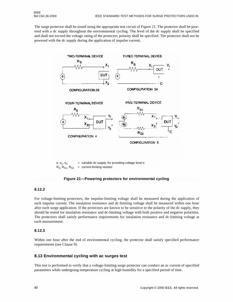
8.1 DC-limiting-voltage test ............................................................................................................ 208.2 Impulse-limiting-voltage test ..................................................................................................... 238.3 Transition current test ................................................................................................................ 268.4 Current-response-time test ......................................................................................................... 278.5 Impulse reset test ....................................................................................................................... 308.6 Current reset test ........................................................................................................................ 308.7 AC life test ................................................................................................................................. 338.8 Impulse life test.......................................................................................................................... 338.9 Maximum single-impulse discharge test ................................................................................... 378.10 Trip endurance test..................................................................................................................... 378.11 Blocking-cycle life test .............................................................................................................. 378.12 Environmental cycling with impulse surges test ....................................................................... 39
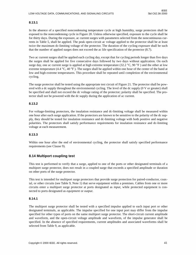
8.13 Environmental cycling with ac surges test ................................................................................ 408.14 Multiport coupling test............................................................................................................... 41
IEEE Standard Test Methods forSurge Protectors Used in Low-Voltage Data, Communications,and Signaling Circuits
1. Scope
This standard applies to surge protectors for application on multiconductor balanced or unbalanced data,communications, and signaling circuits with voltages equal to or less than 1000 V rms, or 1200 V dc. Thesesurge protectors are designed to limit voltage surges, current surges, or both.
This standard describes the methods of testing and criteria for determining the end of life of electrical surgeprotectors used in low-voltage data, communications, and signaling circuits. The surge protectors coveredare multiple-component series or parallel combinations of linear or nonlinear elements, packaged for thepurpose of limiting voltage, current, or both.
This standard is not intended to cover packaged single gas tube, air gap, varistor, or avalanche junctionsurge-protective devices, which are included in IEEE Std C62.31-1987,1 IEEE Std C62.32-1981, IEEE StdC62.33-1982, and IEEE Std C62.35-1987, respectively. Specifically excluded from this standard are testmethods for low-voltage power circuit applications. For protection of wire-line communication facilitiesunder the specialized conditions found at power stations, consult IEEE Std 487-1992.
The tests in this standard are intended as design tests, as defined in the IEEE Dictionary [B1]2, and provide ameans of comparison among various multiple-component surge protectors.
The test criteria and definitions of this standard provide a common engineering language beneficial to usersand manufacturers of multiple-component surge protectors.
1Information on references can be found in Clause 2.2The numbers in brackets correspond to those in the bibliography in Annex D.
IEEEStd C62.36-2000 IEEE STANDARD TEST METHODS FOR SURGE PROTECTORS USED IN
This standard shall be used in conjunction with the following publications. If the following publications aresuperseded by an approved revision, the revision shall apply.
IEEE Std 455-1985 (Reaff 1992), IEEE Standard Test Procedure for Measuring Longitudinal Balance ofTelephone Equipment Operating in the Voice Band.3
IEEE Std 487-1992, IEEE Recommended Practice for the Protection of Wire-Line Communication FacilitiesServing Electric Power Stations.
IEEE Std 743-1995, IEEE Standard Equipment Requirements and Measurement Techniques for AnalogTransmission Parameters for Telecommunications.
IEEE Std C62.1-1989 (Reaff 1994), IEEE Standard for Gapped Silicon-Carbide Surge Arresters for ACPower Circuits.
IEEE Std C62.31-1987 (Reaff 1998), IEEE Standard Test Specifications for Gas-Tube Surge-ProtectiveDevices.
IEEE Std C62.32-1981 (Reaff 1997), IEEE Standard Test Specifications for Low-Voltage Air Gap Surge-Protective Devices.
IEEE Std C62.33-1982 (Reaff 1994), IEEE Standard Test Specifications for Varistor Surge-ProtectiveDevices.
IEEE Std C62.35-1987 (Reaff 2000), IEEE Standard Test Specifications for Avalanche Junction Semicon-ductor Surge Protective Devices.
IEEE Std C62.41-1991(Reaff 1995), IEEE Recommended Practice on Surge Voltages in Low-Voltage ACPower Circuits
IEEE Std C62.45-1992 (Reaff 1997), IEEE Guide on Surge Testing for Equipment Connected to Low-Volt-age AC Power Circuits.
ITU-T Recommendation G.703 (1998), Physical/electrical characteristics of hierarchical digital interfaces.4
3IEEE publications are available from the Institute of Electrical and Electronics Engineers, 445 Hoes Lane, P.O. Box 1331, Piscataway,NJ 08855-1331, USA (http://standards.ieee.org/).4ITU-T publications are available from the International Telecommunications Union, Place des Nations, CH-1211, Geneva 20, Switzer-land/Suisse (http://www.itu.int/).
CAUTION
Because of the voltage and energy levels employed in the majority of tests described herein, all testsshould be considered hazardous. Appropriate caution should be taken in their performance.
IEEELOW-VOLTAGE DATA, COMMUNICATIONS, AND SIGNALING CIRCUITS Std C62.36-2000
This clause contains only those definitions of terms relating to surge protectors, occurring within this stan-dard, that are not given in the IEEE Dictionary [B1].
3.1 blocking voltage: The maximum voltage that can be applied to current-limiting pairs of terminals of asurge protector containing one or more current-protective devices without degradation of the surge protector.
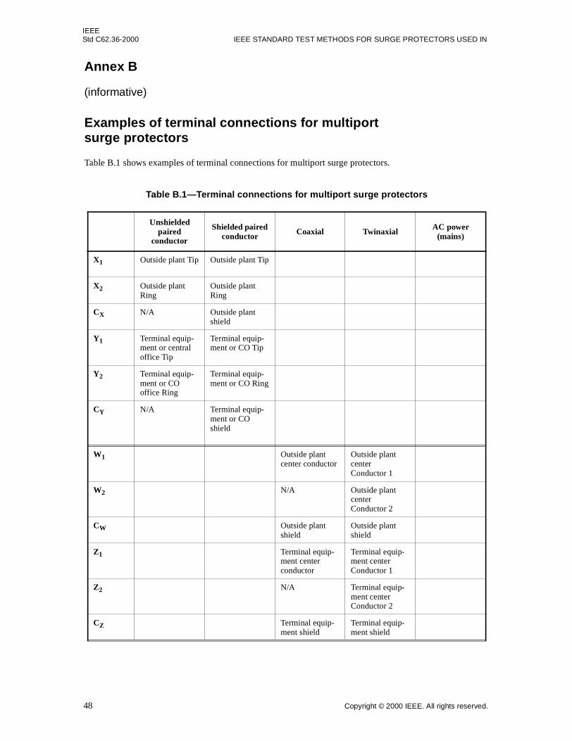
3.2 multiport surge protector: A surge protector that provides surge protective function to two or more cir-cuits, such as, but not limited to, paired conductors, coaxial cables, or mains, whereby all conductorsconnected to the protected circuits are routed through a common enclosure having a shared commonterminal.
3.3 protector: See: surge protector.
3.4 surge protector: An assembly of protective devices consisting of one or more series, parallel, or anycombination of elements used to limit surge voltages, currents, or both to a specified level. Syn: protector.
3.5 transition current: The current required at a given temperature and duration to cause a current-protectivedevice to change state.
4. Service conditions
4.1 Normal service conditions
In the absence of special requirements, the following items should be specified as appropriate.
4.1.1 Environmental conditions
a) Operating and storage temperature rangesb) Humidityc) Mechanical shock and vibrationd) Atmospheric pressure range
4.1.2 Physical properties
a) Solvent resistanceb) Solderabilityc) Flammabilityd) Package rupture during overloade) Electrical connection to metallic case
4.1.3 System conditions
a) Nominal system frequenciesb) Maximum continuous system voltagec) Peak impulse currentsd) Transient repetition rate
IEEEStd C62.36-2000 IEEE STANDARD TEST METHODS FOR SURGE PROTECTORS USED IN
4.1.4 Surge rating of the surge protector under system conditions
a) Rated average power dissipationb) Peak pulse power or current temperature deratingc) Lifetime rated pulse currents
4.2 Unusual service conditions
The following service conditions may require special consideration in the design or application of surge pro-tectors and should be called to the attention of the manufacturer.
4.2.1 Environmental conditions
a) Ambient temperature exceeding the normal service conditionsb) Exposure to
1) Damaging fumes or vapors2) Excessive dirt or current-conducting deposits, excessive humidity, moisture, dripping water,
steam or salt spray, explosive atmospheres, abnormal vibrations, and shocksc) Unusual transportation or storage conditionsd) Flammability rating
4.2.2 Physical conditions
Limitation on weight or space, including clearance to nearby conducting objects.
4.2.3 System conditions
a) System voltages, currents, repetition rates, or frequency operating conditions whereby the ratings ofthe devices are exceeded (see Clause 9)
b) System impulse currents exceeding the rating of the device (see Clause 9)c) Exposure to direct lightning strike (see Clause 9)d) Electromagnetic field effects (see Clause 9)e) Unusual ground potential situations (see Clause 9)f) Any other unusual conditions known to the user
4.3 Radiation
Some protectors may contain radioactive material. Manufacturers of such protectors shall mark them inaccordance with applicable regulations.
5. Basic configurations
This clause illustrates, by functional block diagrams, the surge protectors described by this standard. A pro-tector assembly may be composed of any number of the protectors in Figure 1.
IEEELOW-VOLTAGE DATA, COMMUNICATIONS, AND SIGNALING CIRCUITS Std C62.36-2000
C = common terminalI = current-limiting functionV = voltage-limiting functionX1, X2, Y1, Y2 = signal terminals
Figure 1—Basic configurations
NOTES
1—The V,I designation in Figure 1 indicates that a surge protector may have a voltage-limiting function, a current-limiting function, or both.
2—Surge protectors intended for coaxial cable circuits shall be tested, as described in Clause 7 and Clause 8, usingConfiguration 3A. Outer conductors of the transmission lines are connected to the common terminal of the surgeprotector during the tests. (See examples of surge protectors on coaxial lines in Figure A.2.)
3—Surge protectors intended for twinaxial cable circuits shall be tested, as described in Clause 7 and Clause 8,using Configuration 5. Outer conductors of the transmission lines are connected to the common terminal of the surgeprotector during the tests. (See examples of surge protectors on twinaxial lines in Figure A.3.)
IEEEStd C62.36-2000 IEEE STANDARD TEST METHODS FOR SURGE PROTECTORS USED IN
The design tests described in Clause 7 and Clause 8 provide standardized methods for making single obser-vations of a specified characteristic of a surge protector. These properties may vary from device to device,making it necessary to provide statistical descriptions of the property in order to compare products.
6.2 Statistical procedures
The following procedure shall be used to describe any characteristic that has been determined to have impor-tant statistical aspects. A product sample shall be chosen in a manner consistent with the definition of designtests as provided by the IEEE Dictionary [B1]. A sufficient number of devices shall be tested and the charac-teristic or rating in question measured as described in the applicable design test until the parameters of theunderlying statistical distribution are determined within specified confidence limits. Values relating to theproduct sample, such as, but not limited to, mean, median, maximum, minimum, and standard deviation,may then be stated.
6.3 Test conditions
The tests in Clause 7 and Clause 8 shall be performed on the surge protector as required by the application.Unless otherwise specified, ambient test conditions shall be as follows:
Temperature: 25 °C ± 5 °CRelative humidity: less than 85%Atmospheric pressure: 60–78 cm of Hg
For temperatures other than 25 °C, the surge protector, mounted as intended to be used, shall be maintainedat the specified test temperature but with the air flow controlled to provide a free convection heat transfer,unless otherwise specified. The protector temperature shall be allowed to stabilize before tests are performed.
6.4 Test measurements
General guidance on test measurement techniques that has been useful in measuring the characteristics ofsurge protectors is contained in Annex C.
7. Nonsurge performance tests
The following nonsurge voltage and current tests are intended to establish that, in its quiescent state, thesurge protector does not disturb operation of the protected circuit.
7.1 Rated voltage test
The purpose of this test is to verify that the surge protector can be used continuously at a specified maximumvoltage, frequency, and temperature without undesirable signal distortion, undesirable power loss, or failure.
IEEELOW-VOLTAGE DATA, COMMUNICATIONS, AND SIGNALING CIRCUITS Std C62.36-2000
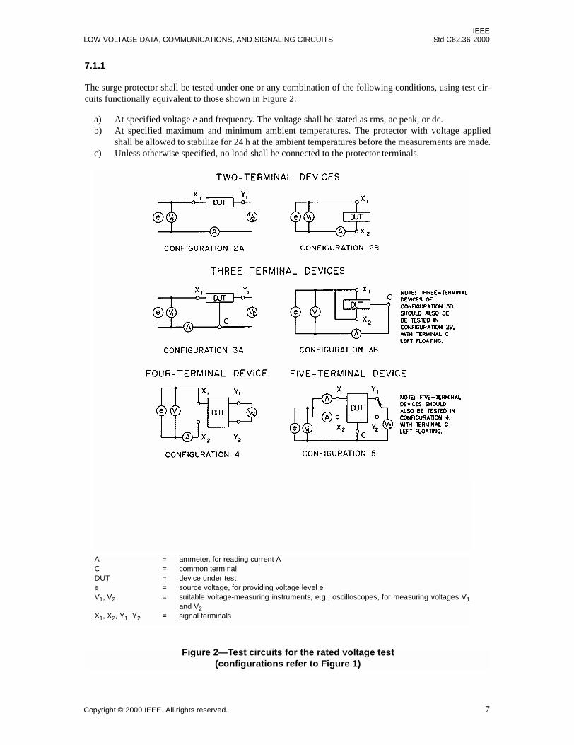
The surge protector shall be tested under one or any combination of the following conditions, using test cir-cuits functionally equivalent to those shown in Figure 2:
a) At specified voltage e and frequency. The voltage shall be stated as rms, ac peak, or dc.b) At specified maximum and minimum ambient temperatures. The protector with voltage applied
shall be allowed to stabilize for 24 h at the ambient temperatures before the measurements are made.c) Unless otherwise specified, no load shall be connected to the protector terminals.
Figure 2—Test circuits for the rated voltage test(configurations refer to Figure 1)
A = ammeter, for reading current AC = common terminalDUT = device under teste = source voltage, for providing voltage level eV1, V2 = suitable voltage-measuring instruments, e.g., oscilloscopes, for measuring voltages V1
and V2X1, X2, Y1, Y2 = signal terminals
IEEEStd C62.36-2000 IEEE STANDARD TEST METHODS FOR SURGE PROTECTORS USED IN
Observe the amplitudes and waveshapes of voltage V1 and voltage V2. Measure the current by means of asuitable ammeter, A, or by a current shunt and an oscilloscope. When making voltage measurements, theammeters shall be removed from the circuit. When making current measurements, the voltage-measuringinstruments shall be removed from the circuit.
7.1.3
After the temperature stabilization period, the surge protector shall not exhibit specified failure modes (seeClause 9) and shall meet the following criteria:
a) The protector shall not limit nor distort voltages V1 or V2 beyond a specified amount.b) The current, A, shall not exceed a specified value at the ambient temperature of the test. (This cur-
rent may be referred to as leakage current.)
7.2 Rated current test
This test is conducted to verify that a surge protector does not degrade normal circuit functions while carry-ing the rated current.
7.2.1
The surge protector is to be tested under the following conditions, using the appropriate test circuit, asshown in Figure 3:
a) At rated frequency, dc, or as specified.b) Maximum ambient temperature of the application, or as specified.c) A continuous current, I, specified by its dc, ac rms, or ac peak value (+5%, –0%), is to be adjusted
by means of the source resistance, Rs, with the protector in the circuit.d) The test shall be conducted until temperature stabilization of the protector occurs.e) The voltages e, e1, and e2 shall be the rated voltage(s). Normally e1 = e2, except where opposite
polarity is an important requirement.f) RL shall approximate the load resistance of the intended application.g) For ungrounded circuit applications, the circuits in Configuration 2A, Configuration 4 (balanced),
and Configuration 4 (unbalanced) of Figure 3 shall be used.h) For multicircuit devices, as many circuits as are expected to be active at the same time shall be
simultaneously exposed to the rated current.
7.2.2
At the conclusion of the test, the surge protector shall not experience a failure mode relevant to the applica-tion (see Clause 9). The voltage across RL shall not have more than a specified increase in total harmonicdistortion as compared to the value measured with the protector replaced by a short circuit. In the absence ofspecified requirements, the increase shall not exceed 1%.
7.3 DC series resistance test
This test is conducted to determine the dc series resistance between specified terminals of a surge protector.
IEEELOW-VOLTAGE DATA, COMMUNICATIONS, AND SIGNALING CIRCUITS Std C62.36-2000
The resistance between specified terminals shall be determined. One pair of terminals shall be measured at atime; all terminals not involved in the measurement shall be left open-circuited. The test current and polarityshall be specified; the current shall be less than or equal to the rated current. The voltage across the testedterminals shall be measured.
The dc series resistance is the measured voltage divided by the test current.
Figure 3—Test circuits for the rated current test
A, A1, A2 = ammeters or oscilloscopes with current shunts, for reading current AC = common terminalDUT = device under teste, e1, e2 = dc or sinewave sources with less than 1% total harmonic distortion, for providing
voltage level eRL, RL1, RL2, RS, RS1, RS2 = noninductive resistorsX1, X2, Y1, Y2 = signal terminals
IEEEStd C62.36-2000 IEEE STANDARD TEST METHODS FOR SURGE PROTECTORS USED IN
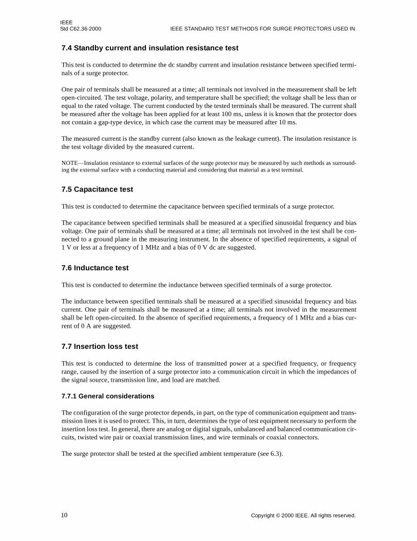
7.4 Standby current and insulation resistance test
This test is conducted to determine the dc standby current and insulation resistance between specified termi-nals of a surge protector.
One pair of terminals shall be measured at a time; all terminals not involved in the measurement shall be leftopen-circuited. The test voltage, polarity, and temperature shall be specified; the voltage shall be less than orequal to the rated voltage. The current conducted by the tested terminals shall be measured. The current shallbe measured after the voltage has been applied for at least 100 ms, unless it is known that the protector doesnot contain a gap-type device, in which case the current may be measured after 10 ms.
The measured current is the standby current (also known as the leakage current). The insulation resistance isthe test voltage divided by the measured current.
NOTE—Insulation resistance to external surfaces of the surge protector may be measured by such methods as surround-ing the external surface with a conducting material and considering that material as a test terminal.
7.5 Capacitance test
This test is conducted to determine the capacitance between specified terminals of a surge protector.
The capacitance between specified terminals shall be measured at a specified sinusoidal frequency and biasvoltage. One pair of terminals shall be measured at a time; all terminals not involved in the test shall be con-nected to a ground plane in the measuring instrument. In the absence of specified requirements, a signal of1 V or less at a frequency of 1 MHz and a bias of 0 V dc are suggested.
7.6 Inductance test
This test is conducted to determine the inductance between specified terminals of a surge protector.
The inductance between specified terminals shall be measured at a specified sinusoidal frequency and biascurrent. One pair of terminals shall be measured at a time; all terminals not involved in the measurementshall be left open-circuited. In the absence of specified requirements, a frequency of 1 MHz and a bias cur-rent of 0 A are suggested.
7.7 Insertion loss test
This test is conducted to determine the loss of transmitted power at a specified frequency, or frequencyrange, caused by the insertion of a surge protector into a communication circuit in which the impedances ofthe signal source, transmission line, and load are matched.
7.7.1 General considerations
The configuration of the surge protector depends, in part, on the type of communication equipment and trans-mission lines it is used to protect. This, in turn, determines the type of test equipment necessary to perform theinsertion loss test. In general, there are analog or digital signals, unbalanced and balanced communication cir-cuits, twisted wire pair or coaxial transmission lines, and wire terminals or coaxial connectors.
The surge protector shall be tested at the specified ambient temperature (see 6.3).
IEEELOW-VOLTAGE DATA, COMMUNICATIONS, AND SIGNALING CIRCUITS Std C62.36-2000
If a surge protector has more than two ports, and the test equipment does not supply terminating provisionsfor the additional ports, then the test shall be performed with the untested ports terminated with the charac-teristic impedance of the circuit.
If specified, a bias voltage or current (not shown in Figure 4) shall be applied to the surge protector.
7.7.2 Measurement at frequencies below 1 MHz
For measurement of insertion loss for surge protectors used in low-frequency circuits (below 1 MHz), wherethe matched impedances of the source, transmission line, and load are not critical, a signal generator (analogor digital) and an oscilloscope may be used.
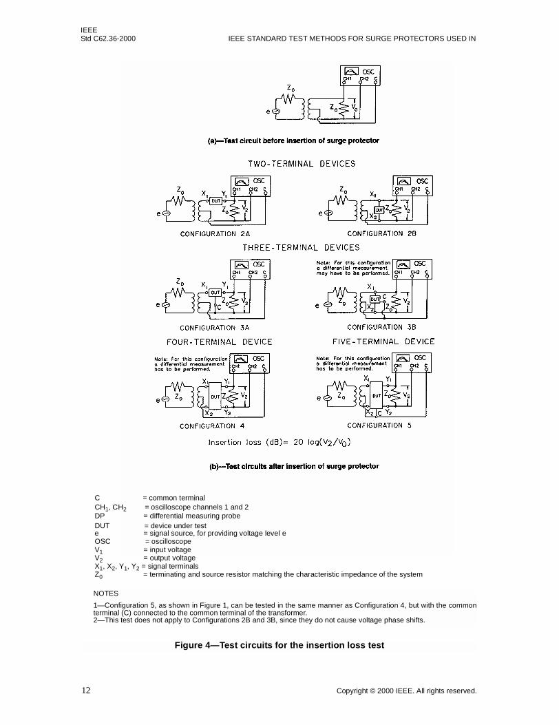
Set up the test circuit as shown in part (a) of Figure 4. Adjust the voltage level, V0, and the frequency of thesignal source as specified. Insert the surge protector between the signal source and the load. Measure thevoltage, V2, as shown in part (b) of Figure 4.
The insertion loss (in decibels) is determined by Equation (1).
Insertion loss = 20 log (V2/V0) (1)
7.7.3 Measurement at frequencies above 1 MHz
There is a wide choice of test equipment available to perform insertion loss tests. An example is a spectrumanalyzer with a tracking generator. The test equipment chosen shall be suitable for the same type of commu-nication system (i.e., analog or digital signals, balanced or unbalanced, twisted pair wire connections orcoaxial connectors), and have the same characteristic impedance, as the circuit for which the surge protectoris designed.
The test equipment is calibrated and operated in accordance with the manufacturer’s instructions and, usu-ally, the cables and connectors needed to insert the surge protector are connected, and their losses are nulledfrom the subsequent measurement of the insertion loss of the surge protector. The surge protector is inserted,and the instrument displays the insertion loss in decibels caused by the surge protector.
If the available test equipment does not provide the proper terminations required by the surge protector, thenadapters, such as connectors or transformers, shall be used. It is important that these adapters have the samecharacteristic impedance as the rest of the circuit, and that the losses caused by the adapters are excluded(nulled) from the insertion loss measurement of the surge protector.
7.8 Phase shift test
This test is conducted to determine the phase shift of a sinusoidal voltage signal of specified frequency, orfrequency range, caused by the insertion of a surge protector into the signal path.
Set up the test circuit as shown in Figure 5. Adjust the voltage level V1 and the frequency as specified. Thesurge protector shall be at the specified ambient temperature (see 6.3). Measure the time delay between thetwo voltage waveshapes as they pass through the 0 V reference line.
NOTE—A specified bias voltage or current (not shown in Figure 5) may be applied to the surge protector.
IEEEStd C62.36-2000 IEEE STANDARD TEST METHODS FOR SURGE PROTECTORS USED IN
Figure 4—Test circuits for the insertion loss test
NOTES
1—Configuration 5, as shown in Figure 1, can be tested in the same manner as Configuration 4, but with the commonterminal (C) connected to the common terminal of the transformer.2—This test does not apply to Configurations 2B and 3B, since they do not cause voltage phase shifts.
C = common terminalCH1, CH2 = oscilloscope channels 1 and 2DP = differential measuring probeDUT = device under teste = signal source, for providing voltage level eOSC = oscilloscopeV1 = input voltageV2 = output voltageX1, X2, Y1, Y2 = signal terminalsZ0 = terminating and source resistor matching the characteristic impedance of the system
IEEELOW-VOLTAGE DATA, COMMUNICATIONS, AND SIGNALING CIRCUITS Std C62.36-2000
The phase shift is determined by converting the time difference into degrees or radians using Equation (2) orEquation (3).
(2)
(3)
where
t is time difference between voltage signals (in seconds),T is period of a full cycle of V1 (in seconds).
7.9 Return-loss test
This test is conducted to determine the amount of power reflected to the signal source over a specifiedfrequency range caused by insertion of the surge protector into a matched transmission line. Return loss ismeasured at a pair of terminals, designated as a port. Terminal pairs generally used for return-loss measure-ments are (Figure 1): X1–C, X2–C, Y1–C, Y2–C, X1–X2, and Y1–Y2.
The surge protector shall be at the specified ambient temperature (see 6.3).
7.9.1 Measurement at frequencies below 1 MHz
Set up the test circuit as shown in part (a) of Figure 6. Adjust the tracking generator voltage and the fre-quency range as specified, and determine the reference return loss of the circuit without the surge protectorby connecting a short circuit to the return-loss bridge so that all incident power is reflected. Record thelevel displayed (in decibels) by the spectrum analyzer. Then insert the surge protector as shown in part (b)of Figure 6.
If specified, a bias voltage or current (not shown in Figure 6) shall be applied to the surge protector. Addi-tional considerations for the measurement of return loss on analog voice frequency circuits are found inIEEE Std 743-1995.
7.9.2 Measurement at frequencies above 1 MHz
At frequencies above 1 MHz, improved accuracy results either from measuring the scattering parameters ofthe surge protector, or from the use of a spectrum analyzer with a tracking generator and a directional cou-pler (sometimes called a return-loss bridge).
Test equipment for return-loss measurements generally includes coaxial connectors. If the surge protectorbeing tested does not have coaxial connectors, an adapter (possibly including a transformer, if the surge pro-tector is of balanced construction) shall be used. If an adapter is used, care shall be taken that the return lossof the adapter does not dominate the return loss of the surge protector. An adapter is inserted between the testsystem and the surge protector as shown in Figure 7.
If the surge protector has more than two ports, then terminate all unused ports in a load having an impedanceequal to the characteristic impedance of the port.
phase shift (degrees)tT--- 360×=
phase shift (radians)tT--- 2× π=
IEEEStd C62.36-2000 IEEE STANDARD TEST METHODS FOR SURGE PROTECTORS USED IN
C = common terminalDUT = device under testRLB = return-loss bridgeSA = spectrum analyzerSC =characteristic short-circuit terminationTG = tracking generatorX1, X2, Y1 = signal terminalsZ0 = terminating resistor matching the characteristic impedance of the system
IEEELOW-VOLTAGE DATA, COMMUNICATIONS, AND SIGNALING CIRCUITS Std C62.36-2000
This method requires a network analyzer and a companion S-parameter measuring set. The measuring setshall have the same characteristic impedance as the network into which the surge protector will be installed.The measuring set is calibrated and operated according to the manufacturer’s instructions. The surgeprotector under test is connected to the measuring set in the manner described by the manufacturer of themeasuring set.
Under these conditions, the return loss of the surge protector is shown in Equation (4).
Return loss = –20 log10 (s11) (4)
where s11 is the fraction of voltage reflected back from the tested port, with all other ports terminated in thecharacteristic impedance of the circuit.
7.9.2.2 Method B—spectrum analyzer
This method uses a spectrum analyzer with a tracking generator and a directional coupler (return-lossbridge) having the same characteristic impedance as the network into which the surge protector will beinstalled. The spectrum analyzer and tracking generator are calibrated and operated according to the manu-facturer’s instructions.
TG SA
DC
DUT Z0AD
AD = AdaptorDC = Directional CouplerDUT = Device Under TestSA = Spectrum AnalyzerTG = Tracking GeneratorZ0 = Load
Figure 7—Circuit for measuring return loss of a surge protector needing an adaptor
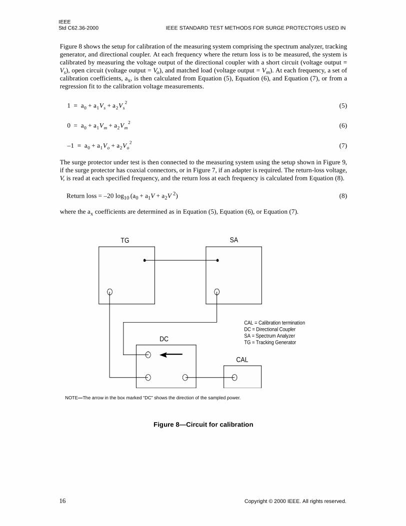
NOTE—The arrow in the box marked “DC” shows the direction of the sampled power.
IEEEStd C62.36-2000 IEEE STANDARD TEST METHODS FOR SURGE PROTECTORS USED IN
Figure 8 shows the setup for calibration of the measuring system comprising the spectrum analyzer, trackinggenerator, and directional coupler. At each frequency where the return loss is to be measured, the system iscalibrated by measuring the voltage output of the directional coupler with a short circuit (voltage output =Vs), open circuit (voltage output = Vo), and matched load (voltage output = Vm). At each frequency, a set ofcalibration coefficients, ax, is then calculated from Equation (5), Equation (6), and Equation (7), or from aregression fit to the calibration voltage measurements.
(5)
(6)
(7)
The surge protector under test is then connected to the measuring system using the setup shown in Figure 9,if the surge protector has coaxial connectors, or in Figure 7, if an adapter is required. The return-loss voltage,V, is read at each specified frequency, and the return loss at each frequency is calculated from Equation (8).
Return loss = –20 log10 (a0 + a1V + a2V 2) (8)
where the ax coefficients are determined as in Equation (5), Equation (6), or Equation (7).
This test is conducted to verify that a surge protector does not unacceptably contribute to the noise of thecircuit to which it is applied. The longitudinal balance test is intended for protectors used on balancedpaired-conductor circuits, such as telephone-type circuits.
7.10.1
Longitudinal balance is a measurement of the degree of symmetry of the impedances to ground (or commonterminal) of the two sides of a network or circuit. It is also used to express the degree of susceptibility tolongitudinal (common mode) interference. The degree of balance is determined by applying a longitudinalcurrent (i.e., a current that travels in the same direction on both conductors of the pair) to the network or cir-cuit under test, and then measuring the resulting metallic (transverse or differential mode) voltage or noiseacross the pair.
7.10.2
Balance measurements shall be made at the nominal circuit operational voltages, currents, and frequenciesappropriate to the expected applications for the circuit being tested. The nominal circuit operational condi-tions, and the longitudinal voltage of the source used for the test, shall be specified.
Connections shown in Figure 4 of IEEE Std 455-1985 shall be used for testing three-terminalsurge-protector configurations, and those shown in part (a) of Figure 5 of the same standard shall be used fortesting four- and five-terminal surge protector configurations.
Figure 9—Circuit for measuring return loss of a surge protector havingcoaxial connectors
NOTE—The arrow in the box marked “DC” shows the direction of the sampled power.
IEEEStd C62.36-2000 IEEE STANDARD TEST METHODS FOR SURGE PROTECTORS USED IN
The longitudinal balance is the ratio of the longitudinal voltage, Vs, and the resulting metallic voltage, Vm, ofthe surge protector under test expressed in decibels, as shown in Equation (9).
Longitudinal balance (dB) = 20 log (Vs/Vm) (9)
where Vs and Vm have the same frequency.
NOTE—To ensure that high levels of longitudinal noise voltage in certain applications do not cause loss of balancebecause of surge protector nonlinearities, the test shall be repeated with the source voltage of the test adjusted to the levelof the longitudinal noise voltage. Verify that there are no significant changes in results.
7.11 Pulse mask test
This test is conducted to verify that a surge protector in a digital circuit does not cause unacceptable distor-tion of the digital information signal.
7.11.1
The surge protector shall be tested in a circuit that is similar to that used for insertion loss (see 7.7). Thesource shall provide a digital data signal, with a bit rate selected from ITU-T Recommendation G.703(1998), using the applicable line code as specified in ITU-T Recommendation G.703 (1998). The impedanceof the source and resistive load shall be as specified in ITU-T Recommendation G.703 (1998) for theselected digital data signal. The pulse mask test shall be performed first across the load without the surgeprotector. Then, the test shall be repeated with the surge protector in place.
7.11.2
An isolated pulse of the selected digital data signal shall fit within its corresponding pulse mask, as specifiedin ITU-T Recommendation G.703 (1998), with or without the presence of the surge protector.
7.12 Rise- and decay-time test
This test is conducted to measure the change, if any, in the slope of the operating-voltage pattern caused byinsertion of the surge protector.
7.12.1
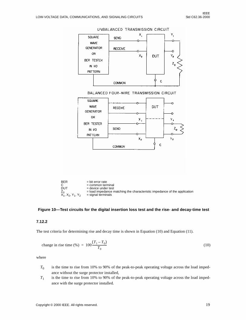
Rise and decay times shall be measured separately in the send and receive circuits. The rise and decay timesof the send circuit shall be measured into a load impedance at the specific rate(s) and voltage levels, with theunspecified terminals unconnected (see Figure 10). The output impedance of the BER tester or square wavegenerator and the load impedance, Z0, shall be set to be equal to the characteristic impedance of the applica-tion. Reconnect the test circuit, substituting the receive circuit for the send circuit, and repeat the procedure.
a) Measure the time to rise from 10% to 90% of the peak-to-peak operating voltage across the charac-teristic impedance with and without the surge protector installed.
b) Measure the time to decay from 90% to 10% of the peak-to-peak operating voltage across the char-acteristic impedance with and without the surge protector installed.
c) Repeat procedures a) and b) for the receive circuit.
IEEELOW-VOLTAGE DATA, COMMUNICATIONS, AND SIGNALING CIRCUITS Std C62.36-2000
The test criteria for determining rise and decay time is shown in Equation (10) and Equation (11).
(10)
where
T0 is the time to rise from 10% to 90% of the peak-to-peak operating voltage across the load imped-
ance without the surge protector installed,T1 is the time to rise from 10% to 90% of the peak-to-peak operating voltage across the load imped-
ance with the surge protector installed.
Figure 10—Test circuits for the digital insertion loss test and the rise- and decay-time test
BER = bit error rateC = common terminalDUT = device under testZ0 = load impedance matching the characteristic impedance of the applicationX1, X2, Y1, Y2 = signal terminals
change in rise time (%) 100T1 T0–( )
T0----------------------=
IEEEStd C62.36-2000 IEEE STANDARD TEST METHODS FOR SURGE PROTECTORS USED IN
T2 is the time to decay from 90% to 10% of the peak-to-peak operating voltage across the load imped-ance without the surge protector installed,
T3 is the time to decay from 90% to 10% of the peak-to-peak operating voltage across the load imped-
ance with the surge protector installed.
7.13 Bit error rate (BER) test
This test is conducted to measure the change, if any, in BER caused by insertion of the surge protector.
7.13.1
Send-circuit and receive-circuit BERs are measured simultaneously (see Figure 11). Using a pseudo-randombit pattern, measure the BER at the specified baud rate(s) and voltage levels with and without the protectorinstalled. The send and receive impedances of the BER testers shall be set to be equal to the characteristicimpedance of the application.
NOTE—In the absence of specified requirements, the duration of the test in seconds shall be 109 divided by the baudrate.
7.13.2
The test criteria for determining BER shall be as shown in Equation (12).
(12)
where
E0 is the BER without the surge protector installed,
E1 is the BER with the surge protector installed.
8. Active performance tests
The tests in this clause are intended to characterize the ability of a surge protector to perform its protectionfunction.
8.1 DC-limiting-voltage test
The purpose of this test is to measure the voltage at which a protector limits slowly rising voltage waveforms.
A slowly rising voltage shall be applied to the applicable protector terminals and measured as shown inTable 1. Figure 12 shows the circuit to be used for this test.
change in decay time (%) 100T3 T2–( )
T2----------------------=
change in BER (%) 100E1 E0–( )
E0----------------------=
IEEELOW-VOLTAGE DATA, COMMUNICATIONS, AND SIGNALING CIRCUITS Std C62.36-2000
A surge protector containing a gap-type device that is not completely shielded from ambient light by meansof packaging shall be placed in total darkness for at least 24 h and tested in this darkened condition withoutexposure to light.
Increase applied voltage V at a rate not to exceed 2000 V/s. Polarity shall be as specified. Terminals not con-nected to the test circuit shall be left open-circuited.
In Figure 12, the voltage V across the terminals under test shall be removed as soon as the specified currenthas been reached (see NOTE). R2 and C are optional and should be modified to suit the energy-handlingcapability of the device under test (DUT). When testing a protector known to contain a gap-type device,values of R1, R2, and C specified in IEEE Std C62.31-1987 or IEEE Std C62.32-1981 shall be used. The dc-limiting voltage is the highest voltage V measured at any current, up to and including a specified current.
NOTE—A crowbar circuit is usually applied to terminate the dc-limiting-voltage test, thereby limiting the energy dissi-pated by the DUT. The method of applying the crowbar may affect the results of the test.
Figure 11—Test circuits for the bit error rate (BER) test
C = common terminalDUT = device under testX1, X2, Y1, Y2 = signal terminals
IEEEStd C62.36-2000 IEEE STANDARD TEST METHODS FOR SURGE PROTECTORS USED IN
Table 1—Standard terminal combinations for the dc-limiting-voltage test using Figure 12
Basic configuration(number of terminals)
Terminal combination to betested and measured
(both polarities)
2a Not applicable
2b X1–X2
3a X1–C
3a Y1–C
3b X1–C
3b X2–C
3b X1–X2
4 X1–X2
4 Y1–Y2
5 X1–C
5 X2–C
5 X1–X2
5 Y1–C
5 Y2–C
5 Y1–Y2
Figure 12—Test circuit for the dc-limiting-voltage test
A = dc ammeter, for reading current AC = charging capacitor, 0.1 µFe = variable dc supply, for providing voltage level eR1 = charging resistorR2 = current-limiting resistorT1, T2 = test terminalsV = dc voltmeter, for reading voltage V
IEEELOW-VOLTAGE DATA, COMMUNICATIONS, AND SIGNALING CIRCUITS Std C62.36-2000
This test is conducted to measure the voltage at which a protector limits a specified fast-rising impulse.
8.2.1
The protector shall be tested with a specified impulse applied to the terminals as shown in Table 2, as appli-cable. Impulses are to be applied to all applicable terminal combinations, with both positive and negativepolarities, using the appropriate test circuits of Figure 13.
Short-circuit current amplitude and waveform of the impulse generator shall be specified. In the absence ofspecified requirements, current amplitudes and associated waveforms shall be selected from Table 3, asapplicable. Not all current amplitudes and waveforms of Table 3 are compatible with the suggested voltagerate-of-rise. The selected currents shall be within the rated capability of the protector. These currents are theper-terminal-pair suggested currents. For tests using three terminals, these currents are the currents in eachbranch under test. Both terminal pairs shall be tested at the same time and same polarity.
The impulse-limiting voltage shall be measured at a specified rate-of-rise. In the absence of a specified rate-of-rise, the open-circuit output voltage of the impulse generator should be selected from 100 V/µs, 500 V/µs,1 kV/µs, 5 kV/µs, or 10 kV/µs (Figure 14).
Table 2—Standard terminal combinations for the impulse-limiting-voltage testusing Figure 13
Basic configuration(number of terminals)
Terminal combination tobe tested and measured
(both polarities)
2a Not applicable
2b X1–X2
3a X1–C
3a Y1–C
3b X1–C
3b X2–C
3b X1–X2
4 X1–X2
4 Y1–Y2
5 X1–C
5 X2–C
5 X1–X2
5 Y1–C
5 Y2–C
5 Y1–Y2
IEEEStd C62.36-2000 IEEE STANDARD TEST METHODS FOR SURGE PROTECTORS USED IN
Voltage-measuring instruments, V (Figure 13), with appropriate frequency response, shall be used to recordthe peak value of the impulse-limiting voltage of the protector on all applicable combinations of terminals.Impulse-limiting voltage shall be measured both with an open circuit (RL, RL1, and RL2 = ∞) and, whereappropriate, terminated with load resistors RL, RL1, and RL2.
8.2.3
The test conditions (Figure 13) for determining impulse-limiting voltage are as follows:
a) The test shall be performed at the specified ambient temperature.b) If applicable, the dc voltages e, e1, and e2 shall be specified for the application and shall not exceed
the rated voltage of the protector.c) RS, RS1, and RS2 shall be adjusted so that I, I1, and I2 are the bias currents specified for the application.d) RL, RL1, and RL2, as required, shall be the load resistances for the intended application.e) The isolation device of Figure 13 passes the impulse current, but blocks I, I1, and I2 from the
impulse generator. It is typically a diode or spark gap.f) Sufficient time between impulses shall be allowed to prevent thermal accumulation.g) The impulse-limiting voltage is the measured peak voltage between the appropriate terminals of the
protector. In some cases, the measured peak voltage may occur well after the peak of the generator cur-rent. For each test current waveform used, at least one impulse-limiting voltage measurement shall bemade over a time interval that is at least 5 times the virtual time to half-value for that waveform.
Table 3—Suggested short-circuit amplitudes and waveforms for theimpulse-limiting-voltage test
Peak current (A) Waveform (µs)
10 10/1000
50 10/1000
100 10/1000
300 10/1000
500 10/1000
1000 10/250
2000 10/250
1000 8/20
2000 8/20
5000 8/20
500 10/350
1000 10/350
2500 10/350
IEEELOW-VOLTAGE DATA, COMMUNICATIONS, AND SIGNALING CIRCUITS Std C62.36-2000
Figure 13—Test circuits for the impulse-limiting-voltage test
C = common terminalDUT = device under teste, e1, e2 = dc power supplies, for providing voltage level eI, I1, I2 = bias currentRL, RL1, RL2 =load resistorsRS, RS1, RS2 = resistors for adjusting bias currentsV = voltage measuring instrument of appropriate frequency response, for measuring voltage VX1, X2, Y1, Y2 = signal terminals
IEEEStd C62.36-2000 IEEE STANDARD TEST METHODS FOR SURGE PROTECTORS USED IN
The purpose of this test is to verify the current level required to cause a current-protective device in a surgeprotector to change state at a given ambient temperature and within a specified duration.
The surge protector, mounted as intended to be used, shall be placed in a chamber maintained at the speci-fied test temperature. The air flow shall be controlled to provide a free-convection heat-transfer environmentwith the protector shielded from direct flow of forced air. The surge protector shall be allowed to stabilize atthe test temperature.
Specified terminal pairs containing a current-protective device shall be connected in series with a dc or acvoltage source of specified frequency, a specified load resistance, and an ammeter or oscilloscope with cur-rent shunt, as shown in Figure 15. (Configurations are from Figure 1).
The open-circuit voltage of the source(s) e, e1, and e2 shall be the specified blocking voltage of the current-protective devices. For each surge-protector configuration, a specified load current, up to rated current,shall be applied by adjusting RS, RS1, and RS2 during the stabilization period (Figure 15). Next, the sourceresistances RS, RS1, and RS2 shall be reduced such that the load current increases to a level at or above thetransition current level.
The transition current shall be applied until the current in the load resistor ceases or is reduced to a specifiedvalue that indicates that the current-protective device has operated.
The current-protective device shall interrupt or reduce the current in the load resistor within a specified timeafter the transition current has been applied.
Figure 14—Impulse-limiting-voltage test waveform
IEEELOW-VOLTAGE DATA, COMMUNICATIONS, AND SIGNALING CIRCUITS Std C62.36-2000
1—Where specified, either e1 or e2 in the unbalanced network configurations of Figure 15 may be set to zero. This maybe done to establish the maximum time for transition if surge protectors contain components with thermal interaction.
2—This test may be conducted as an extension of the current reset test in 8.6 in order to minimize repetition of tests.
3—Some automatic reset-type current-protective devices may return to their original state within a specified time. Cur-rent-protective devices that are designed to operate only one time, such as fuses, shall remain in the post-transition state.
8.4 Current-response-time test
This test is conducted to determine the time required for the load current to decline to a specified value aftera source current is applied to a current-protective device.
Figure 15—Test circuits for the transition current test
A, A1, A2 = ammeter or oscilloscope with current shunt, for reading current AC = common terminalDUT = device under teste, e1, e2 = power sources, for providing voltage level eRL, RL1, RL2, RS, RS1, RS2 = noninductive resistorsS = switchX1, X2, Y1, Y2 = signal terminals
IEEEStd C62.36-2000 IEEE STANDARD TEST METHODS FOR SURGE PROTECTORS USED IN
The current-limiting protector, mounted as intended to be used, shall be placed in a chamber maintained atthe specified test temperature. The air flow shall be controlled to provide a free-convection heat-transferenvironment, unless otherwise specified. The current-protective device shall then be allowed to stabilize atthe test temperature. A load current, up to the rated current of the DUT, may be applied during the stabiliza-tion period, if specified.
Using the test circuits shown in Figure 16, the dc supply, e, is adjusted to a specified value. Table 4 showsthe open and closed condition of the various switches for each network and its corresponding calibration andtest procedure. Calibration for specified load current shall be accomplished by shorting the DUT and adjust-ing the load network resistors. In the case of a four- or five-terminal device, RL3 and RL4 have been added fora second load current. When two load currents are employed, each may be adjusted to different load currentvalues, as specified.
To adjust for the abnormal test current, all switches are placed in the closed position, and the source resistor,RS, is adjusted to obtain the specified abnormal test current.
Figure 16—Test circuits for the current-response-time test
A = ammeter or oscilloscope with current shunt, for reading current AC = common terminalDUT = device under teste, e1, e2 = power supply, for providing voltage level eRS, RL1, RL2, RL3, RL4 = noninductive resistorsS1, S2, S3 = switchesX1, X2, Y1, Y2 = signal terminals
IEEELOW-VOLTAGE DATA, COMMUNICATIONS, AND SIGNALING CIRCUITS Std C62.36-2000
The response-time measurement is obtained by the following procedure. Switch Sl and/or Switch S3 is to beclosed, timing initiated, and the time required to achieve the transition current level recorded.
NOTE—The ratio of RL1 to RL2 and RL3 to RL4 shall be such that when RS is placed in parallel with RL1 or RL3, theresulting abnormal current will exceed the transition current level of the DUT.
Table 4—Switch status and test procedures for the current-response-time testusing test circuits of Figure 16
Numberof
protectorterminals
S1 S2 S3 S4 Calibration and test procedure
2 O O N/A N/A Set load current
2 S S N/A N/A Set abnormal current
2 O O N/A N/A Stabilize
2 S O N/A N/A Measure time of current decline
3 O O N/A N/A Set load current
3 S S N/A N/A Set abnormal current
3 O O N/A N/A Stabilize
3 S O N/A N/A Measure time of current decline
4 O O O O Set load currents
4 S S S S Set abnormal currents
4 O O O O Stabilize
4 S O S O Measure times of current declines
4 O O O O Set load currents
4 S S O O Set abnormal current, RL1, RL2
4 O O O O Stabilize
4 S S O O Measure times of current declines
4 O O O O Set load currents
4 O O S S Set abnormal current, RL3, RL4
4 O O O O Stabilize
4 O O S S Measure times of current decines
4B O O O N/A Set load current
4B S S S N/A Set abnormal current
4B O O O N/A Stabilize
4B S O O N/A Measure time of current decline
NOTE—A five-terminal device is tested in the same manner as a four-terminal unbalanced network.KEY: 4B = four-terminal balanced network
O = open switchS = closed switchN/A = not applicable
IEEEStd C62.36-2000 IEEE STANDARD TEST METHODS FOR SURGE PROTECTORS USED IN
The purpose of this test is to verify that the surge protector, when connected in a simulated application cir-cuit, reverts to its quiescent state within a specified duration after having limited an impulse.
8.5.1
The surge protector shall be tested under the following conditions, using the appropriate test circuit ofFigure 17:
a) The test shall be performed at specified ambient temperature.b) The dc power sources e, e1, and e2 shall be specified for the application, and their output voltages
shall not exceed the rated voltage of the surge protector.c) RS, RS1, and RS2 shall be adjusted such that I, I1, and I2 are the currents specified for the application,
with the DUT and the load resistors short-circuited.d) RL, RL1, and RL2, as required, shall be the load resistances for the intended application.e) The short-circuit current from the impulse generator shall be specified for the application.f) The isolating device of Figure 17 passes the impulse current but prevents currents I, I1, and I2 from
entering the impulse generator. It is typically a diode or spark gap.g) Some shunt-connected voltage limiters may require the addition of shunt components to assist in
reverting to the quiescent state.
8.5.2
The surge protector shall be subjected to a specified impulse waveform of the same polarity as e, e1, and e2.Where applicable, the test shall be repeated with the polarity of the impulse and e, e1, and e2 reversed. In theabsence of specified requirements, an impulse current waveform of 10/1000 µs should be used (waveshapedesignation defined in IEEE Std C62.1-1989). Voltage V or current A, as applicable, shall be monitored dur-ing the test to determine the period of time for the surge protector to revert to its quiescent state.
The surge protector shall revert to its quiescent state within the specified duration.
8.6 Current reset test
The purpose of this test is to verify that resettable, series-connected, current-protective devices in a surgeprotector revert to their quiescent state within a specified duration after having limited an abnormal current.
8.6.1
The surge protector, mounted as intended to be used, shall be placed in a chamber maintained at the specifiedtest temperature. The air flow shall be controlled to provide a free-convection heat-transfer environment,unless otherwise specified. The surge protector shall be allowed to stabilize at the test temperature. A loadcurrent, up to the rated current, shall be applied by adjusting the source resistors RS, RS1, and RS2 during thestabilization period (Figure 18). For each surge-protector configuration, specified terminal pairs containing acurrent-protective device shall be connected in series with a dc or an ac current source of specified currentand frequency (e, e1, e2), a specified load resistor (RL, RL1, RL2), and an ammeter or oscilloscope with currentshunt, as shown in Figure 18.
8.6.2
The source resistors RS, RS1, and RS2 shall be reduced such that the load current increases to a level at orabove the transition current level. This current shall be applied until the current in the load resistor ceases oris reduced to a specified value that indicates that the current-protective device has operated.
IEEELOW-VOLTAGE DATA, COMMUNICATIONS, AND SIGNALING CIRCUITS Std C62.36-2000
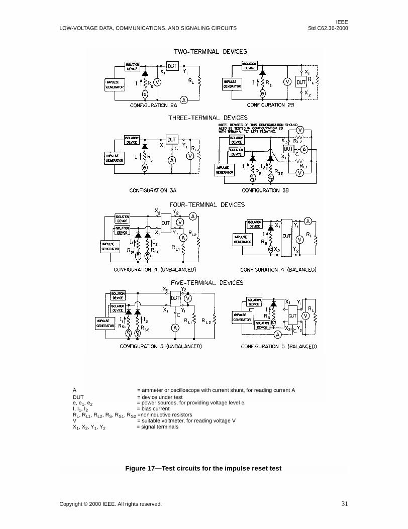
Figure 17—Test circuits for the impulse reset test
A = ammeter or oscilloscope with current shunt, for reading current ADUT = device under teste, e1, e2 = power sources, for providing voltage level eI, I1, I2 = bias currentRL, RL1, RL2, RS, RS1, RS2 =noninductive resistorsV = suitable voltmeter, for reading voltage VX1, X2, Y1, Y2 = signal terminals
IEEEStd C62.36-2000 IEEE STANDARD TEST METHODS FOR SURGE PROTECTORS USED IN
The surge protector shall then be allowed to stabilize until the load current reaches an equilibrium value. Atthis time, the source resistors RS, RS1, and RS2 shall be increased to their pretransition values, and the time inwhich it takes for the load current to return to a specified percentage of its pretransition level shall berecorded.
NOTES
1—Some current-limiting devices in selected applications may not revert to the pretransition quiescent state withoutinterruption of the bias sources e, e1, and e2.
2—Where specified, either e1 or e2 in the unbalanced network configurations of Figure 18 may be set to zero. This maybe done to establish the maximum time for return to the pretransition quiescent state if surge protectors contain compo-nents with thermal interaction.
3—This test may be conducted as an extension of the transition current test of 8.3 in order to minimize repetition of tests.
The load current shall return to within a specified percentage of the pretransition quiescent state within aspecified period of time after the transition current has been removed.
Figure 18—Test circuits for the current reset test, trip endurance test,and blocking cycle life test
C = common terminalDUT = device under teste, e1, e2 = dc or ac sources, for providing voltage level eRL, RL1, RL2, RS, RS1, RS2 =noninductive resistorsS = switchX1, X2, Y1, Y2 = signal terminals
A, A1, A2 = ammeters or oscilloscopes with current shunt, for reading current A
IEEELOW-VOLTAGE DATA, COMMUNICATIONS, AND SIGNALING CIRCUITS Std C62.36-2000
This test is performed to verify that a surge protector can conduct alternating current of specified parametersfor a given number of repetitions without experiencing a failure mode relevant to the application (seeClause 9).
8.7.1
The surge protector shall be tested with the terminal configurations in Figure 19 at the following conditions,to be specified:
a) Peak value of the ac voltage V, V1, or V2 measured across the terminals of the DUT with the DUTreplaced with an open circuit.
The peak value of the open-circuit ac voltage applied to the surge protector shall be at least twice themaximum dc-limiting voltage of the protector. For current-limiting devices, V, V1, or V2 shall be therated voltage.
For protectors with an ac rated voltage, at least twice that voltage should be used. In order to testsurge protectors that may have blind spots (see IEEE Std C62.45-1992), ac life tests shall be run atlower open-circuit ac voltages; unless otherwise specified, 80% of the maximum dc-limiting voltageshall be used.
b) RMS value of ac current A measured with the DUT replaced with a short circuit across all its termi-nals. Adjust RS, RS1, or RS2 to give the specified value.
c) Frequency of the source e. In the absence of specified requirements, 50 Hz or 60 Hz should be used.
d) Number of operations. Each operation may be sufficiently separated in time to avoid thermal accu-mulation in the surge protector.
e) Duration of each operation.
f) Load resistor RL, RL1, and RL2.
NOTE—In the absence of specified current level and test duration, it is recommended that ac life-test parameters beselected from Table 5. Measurement of specified performance parameters shall be done after each operation. It is recom-mended that insulation resistance, dc-limiting voltage, and impulse-limiting voltage be measured after each ac life-testsurge, in that order.
8.7.2
Record whether the surge protector satisfies a predetermined set of operating parameters after exposure tothe specified number of operations without experiencing a failure mode relevant to the application (seeClause 9).
8.8 Impulse life test
This test is performed to verify that a surge protector can conduct an impulse current of specified parame-ters, for a given number of repetitions, without experiencing a failure mode relevant to the application (seeClause 9).
8.8.1
For a specified number of surge protectors, first determine both the maximum and minimumimpulse-limiting voltage using a voltage rate-of-rise of 100 V/µs, unless otherwise specified.
IEEEStd C62.36-2000 IEEE STANDARD TEST METHODS FOR SURGE PROTECTORS USED IN
The surge protector shall then be connected to an impulse-current generator capable of providing, in theabsence of specified requirements, one or more of the waveforms listed in Table 6. The short-circuit currentwaveforms in Table 6 are obtained when all generator terminals are short-circuited.
The currents of Table 6 are the per-terminal-pair suggested currents. For tests using three-terminal surgeprotectors, these currents are applied to each branch under test (i.e., both line terminals shall be exposed tothe same current and polarity simultaneously with respect to the common terminal). Table 7 lists the termi-nal-pair combinations for each basic configuration. For basic Configuration 4, terminals X1, X2 or Y1, Y2may be connected together to create a common terminal for the simultaneous test.
The peak open-circuit voltage of the impulse generator shall exceed the maximum impulse-limiting voltagedetermined in 8.8.1 at the input of the surge protector under test by not less than 50%.
Separate samples shall be tested for each test current waveform and polarity used. The voltage rate-of-rise ofthe impulse life surge shall be specified. Sufficient time between impulses shall be allowed to prevent ther-mal accumulation in the surge protector under test. Unless otherwise specified, the intersurge time shall beas listed in Table 6.
Table 6—Suggested short-circuit current amplitudes, time between impulses, andwaveform pulse life test
Peak short-circuitcurrent (A)
Maximum timebetween impulses
(min)Waveform (µs)
10 2 10/1000
50 2 10/1000
100 2 10/1000
300 2 10/1000
500 2 10/1000
1 000 5 10/250
2 000 5 10/250
5 000 5 8/20
10 000 5 8/20
20 000 5 8/20
500 2 10/350
1 000 2 10/350
2 500 2 10/350
IEEEStd C62.36-2000 IEEE STANDARD TEST METHODS FOR SURGE PROTECTORS USED IN
In order to test surge protectors that may have blind spots (see IEEE Std C62.45-1992), impulse life testsshall be conducted using peak open-circuit voltages that are lower than those in 8.8.2. The peak open-circuitvoltage of the generator during impulse life tests for blind spots shall be 80% of the minimum impulse volt-age obtained in 8.8.1, unless otherwise specified. The same impulse test generator waveform and internalimpedance as selected for use in 8.8.2 shall be used, but at a lower peak open-circuit voltage.
8.8.4
Refer to Clause 9 for failure criteria. In the absence of specified requirements, measurements of insulationresistance, dc-limiting voltage, and impulse-limiting voltage shall be made before each impulse-life testsurge. At the completion of the test, the dc series resistance test shall be performed.
Table 7—Standard terminal combinations for the impulse life test
Basic configuration Test terminals Other terminalsa
2A X1 – Y1 Not applicable
2B X1– X2 Not applicable
3A X1 – C Y1 – C
3A Y1 – C X1 – C
3B X1 – C X2 – C
3B X2 – C X1 – C
3B X1 – X2 Not applicable
3B X1 – Cb
X2 – CbNot applicable
4 X1 – X2 Y1 – Y2
4 Y1 – Y2 X1 – X2
4 X1 – Y1b
X2 – Y2b
Not applicable
5 X1 – C Y1 – C
5 X2 – C Y2 – C
5 X1 – Cb
X2 – CbY1 – CY2 – C
5 Y1 – C X1 – C
5 Y2 – C X2 – C
5 Y1 – Cb
Y2 – CbX1 – CX2 – C
5 X1 – X2 Y1 – Y2
5 Y1 – Y2 X1 – X2
aThese terminals, depending on specific requirements, may be connected with aspecified impedance 0 ≤ Z < ∞.
bBoth sets of terminals are tested simultaneously.
IEEELOW-VOLTAGE DATA, COMMUNICATIONS, AND SIGNALING CIRCUITS Std C62.36-2000
This test is conducted to determine the capability of a surge protector to conduct a specified current impulsewithout experiencing a failure mode relevant to the application (see Clause 9).
A surge protector shall be tested only once with an impulse; different samples shall be tested for each polar-ity or waveform.
In the absence of specified requirements, an impulse-current waveform of either 8/20 µs or 10/1000 µs isrecommended. (Waveform designation is defined in IEEE Std C62.1-1989.) The peak value of the currentwaveform shall be as specified. (See Table 8 for test configurations.) After application of the currentimpulse, the surge protector shall be tested for any relevant failure modes (see Clause 9), which shall then beverified. Terminal combinations appropriate to the application shall be specified for testing. For basic Con-figuration 4, terminals X1, X2 or Y1, Y2 may be connected together to create a common terminal for thesimultaneous test. Different peak current levels and waveforms may be appropriate for various combinationsof surge protector terminals. None of the relevant failure modes shall occur.
8.10 Trip endurance test
This test is performed to verify that, after being subjected to an extended fault condition, a surge protectorcontaining a positive-temperature-coefficient (PTC) current-protective device continues to function.
8.10.1
The surge protector, mounted as intended to be used, shall be placed in a chamber maintained at the speci-fied test temperature. Air flow shall be controlled to provide a free convection heat transfer environmentwith the protector shielded from direct flow of forced air. The surge protector shall be allowed to stabilize atthe test temperature.
8.10.2
For each appropriate surge protector configuration shown in Figure 18, specified terminal pairs containing aPTC current-protective device shall be connected in series with a dc or ac voltage source(s) e, e1, or e2, anda specified load resistance RL, RL1, or RL2. The voltage source(s) shall have an open-circuit voltage equal tothe blocking voltage of the PTC device. An initial specified current that is greater than the transition currentshall be applied by adjusting the source resistance RS, RS1, and RS2 of Figure 18. The level of current is indi-cated on ammeters A, A1, and A2. The duration of application of the current shall be specified. After thespecified duration, the output of the voltage source(s) is reduced to 0 V.
8.10.3
At a specified time after reducing the voltage source(s) to zero, the surge protector shall satisfy specifiedperformance requirements (see Clause 9).
8.11 Blocking-cycle life test
This test is performed to verify that a surge protector containing a positive-temperature-coefficient (PTC)current-protective device continues to function after being subjected to repeated fault conditions.
IEEEStd C62.36-2000 IEEE STANDARD TEST METHODS FOR SURGE PROTECTORS USED IN
The surge protector, mounted as intended to be used, shall be placed in a chamber maintained at the speci-fied test temperature. Air flow in the chamber shall be controlled to provide a free convection heat transferenvironment with the protector shielded from direct flow of forced air. The surge protector shall be allowedto stabilize at the test temperature.
8.11.2
For each appropriate surge protector configuration of Figure 18, specified terminal pairs containing a PTCcurrent-protective device shall be connected in series with a dc or ac voltage source(s) e, e1, or e2, and aspecified load resistance RL, RL1, or RL2. The open-circuit output of the voltage source(s) is the specifiedblocking voltage of the PTC device. A specified current, which shall be greater than the transition current,shall be applied by adjusting the source resistance RS, RS1, and RS2 of Figure 18. During this adjustment, theprotector temporarily is removed from the circuit and is replaced by a resistor equal to the dc series resis-tance of the PTC device (see 7.3). The level of current, as indicated on ammeters A, A1, and A2, may affectresults of the blocking-cycle life test.
After a specified duration, the current is reduced to zero by setting the output of the voltage source(s) to 0 V,and the protector is allowed to remain unpowered for a specified period of time. During its unpoweredperiod the device shall return to its low-resistance state. (This state is indicated by the current in the devicejust after the source(s) are reapplied.) This cycle of applying current, followed by an unpowered period,shall be repeated a specified number of times.
Table 8—Standard terminal combinations for maximum, single-impulse discharge test
Basic configuration Test terminals Other terminalsa
2A X1 – Y1 Not applicable
2B X1 – X2 Not applicable
3A X1 – C Y1 – C
3A Y1 – C X1 – C
3B X1 – X2 Not applicable
3B X1 – Cb
X2 – CbNot applicable
4 X1 – X2 Y1 – Y2
4 Y1 – Y2 X1 – X2
4 X1 – Y1b
X2 – Y2b
Not applicable
5 X1 – Cb
X2 – CbY1 – CY2 – C
5 Y1 – Cb
Y2 – CbX1 – CX2 – C
5 X1 – X2 Y1 – Y2
5 Y1 – Y2 X1 – X2
aThese terminals, depending on specific requirements, may be connected with aspecified impedance 0 ≤ Z < ∞.
bBoth sets of terminals are tested simultaneously.
IEEELOW-VOLTAGE DATA, COMMUNICATIONS, AND SIGNALING CIRCUITS Std C62.36-2000
At a specified time after reducing the current to zero at the end of the final cycle, the surge protector shallsatisfy specified performance requirements (see Clause 9).
8.12 Environmental cycling with impulse surges test
This test is performed to verify that a voltage-limiting surge protector can conduct surges of specifiedparameters while undergoing temperature cycling at high humidity for a specified period of time.
8.12.1
In the absence of a specified noncondensing temperature cycle at high humidity, surge protectors shall beexposed to the noncondensing environmental cycle in Figure 20. Unless otherwise specified, exposure to thecycle shall be for thirty days. During the exposure, impulse currents with a peak open-circuit voltage,exceeding the maximum impulse-limiting voltage of the DUT determined in 8.2, with a specified rate-of-rise, shall be applied. A specified short-circuit current waveform selected from Table 6 shall also be applied.The duration of the cycling exposure shall be such that the number of applied surges does not exceed theImpulse Life specification of the protector (8.8).
Two impulse currents shall be applied each cycling day, except that for cycling periods longer than five daysthe surges shall be applied for five consecutive days followed by two days without application. On eachsurge day, one impulse current is applied at high extreme temperature (32.2 °C, 90 °F ) and the other at lowextreme temperature (4.4 °C, 40° F ). The surges shall be applied within one hour of the center of the band atlow and high extreme temperatures. The impulse currents on a given day shall be of the same polarity, butshall alternate polarity every other day. This procedure shall be repeated until completion of the environmen-tal cycling.
Figure 20—Environmental cycling test with relative humidity at 90% or greater
IEEEStd C62.36-2000 IEEE STANDARD TEST METHODS FOR SURGE PROTECTORS USED IN
The surge protector shall be tested using the appropriate test circuit of Figure 21. The protector shall be pow-ered with a dc supply throughout the environmental cycling. The level of the dc supply shall be specifiedand shall not exceed the voltage rating of the protector; polarity shall be specified. The protector shall not bepowered with the dc supply during the application of impulse current.
8.12.2
For voltage-limiting protectors, the impulse-limiting voltage shall be measured during the application ofeach impulse current. The insulation resistance and dc-limiting voltage shall be measured within one hourafter each surge application. If the protectors are known to be sensitive to the polarity of the dc supply, theyshould be tested for insulation resistance and dc-limiting voltage with both positive and negative polarities.The protectors shall satisfy performance requirements for insulation resistance and dc-limiting voltage ateach measurement.
8.12.3
Within one hour after the end of environmental cycling, the protector shall satisfy specified performancerequirements (see Clause 9).
8.13 Environmental cycling with ac surges test
This test is performed to verify that a voltage-limiting surge protector can conduct an ac current of specifiedparameters while undergoing temperature cycling at high humidity for a specified period of time.
Figure 21—Powering protectors for environmental cycling
e, e1, e2 = variable dc supply, for providing voltage level eRS, RS1, RS2 = current-limiting resistor
IEEELOW-VOLTAGE DATA, COMMUNICATIONS, AND SIGNALING CIRCUITS Std C62.36-2000
In the absence of a specified noncondensing temperature cycle at high humidity, surge protectors shall beexposed to the noncondensing cycle in Figure 20. Unless otherwise specified, exposure to the cycle shall befor thirty days. During the exposure, ac current surges with parameters selected from the noncontinuous cur-rents in Table 5, shall be applied. The peak open-circuit ac voltage applied to the protector shall be at leasttwice the maximum dc-limiting voltage of the protector. The duration of the cycling exposure shall be suchthat the number of applied surges does not exceed the ac life specification of the protector (8.7).
Two ac current surges shall be applied each cycling day, except that for cycling periods longer than five daysthe surges shall be applied for five consecutive days followed by two days without application. On eachsurge day, one ac current surge is applied at high extreme temperature (32.2 °C, 90 °F ) and the other at lowextreme temperature (4.4 °C, 40 °F ). The surges shall be applied within one hour of the center of the band atlow and high extreme temperatures. This procedure shall be repeated until completion of the environmentalcycling.
The surge protector shall be tested using the appropriate test circuit of Figure 21. The protector shall be pow-ered with a dc supply throughout the environmental cycling. The level of the dc supply (0 V or greater) shallbe specified and shall not exceed the dc voltage rating of the protector; polarity shall be specified. The pro-tector shall not be powered with the dc supply during the application of ac current.
8.13.2
For voltage-limiting protectors, the insulation resistance and dc-limiting voltage shall be measured withinone hour after each surge application. If the protectors are known to be sensitive to the polarity of the dc sup-ply, they should be tested for insulation resistance and dc-limiting voltage with both positive and negativepolarities. The protectors shall satisfy performance requirements for insulation resistance and dc-limitingvoltage at each measurement.
8.13.3
Within one hour after the end of environmental cycling, the protector shall satisfy specified performancerequirements (see Clause 9).
8.14 Multiport coupling test
This test is performed to verify that a surge, applied to one of the ports or other designated terminals of amultiport surge protector, does not result in a coupled surge that exceeds a specified amplitude or durationon other ports of the surge protector.
This test is intended for multiport surge protectors that provide surge protection for paired-conductor, coax-ial, or other circuits (see Table 9, Note 1) that serve equipment within a premises. Cables from one or morecircuits enter a multiport surge protector at ports designated as input, while protected equipment is con-nected to ports designated as equipment or output.
8.14.1
The multiport surge protector shall be tested with a specified impulse applied to each input port or otherdesignated terminals, as applicable. The impulse specified for one input port may differ from the impulsespecified for other types of ports on the same multiport surge protector. The short-circuit current amplitudeand waveform, and the open-circuit voltage amplitude and waveform, of the impulse generator shall bespecified. In the absence of specified requirements, current amplitudes and associated waveforms shall beselected from Table 9, as applicable.
IEEEStd C62.36-2000 IEEE STANDARD TEST METHODS FOR SURGE PROTECTORS USED IN
The impulse current shall be applied at each applicable port, separately and not simultaneously, between eachapplicable line and common terminal or other designated terminals; and the resulting coupled voltage andwaveform shall be measured at each of the other ports, between the line and common terminals or other des-ignated terminals. See Table 10 for combinations of terminal pairs to be tested with reference to Figure 22.
Table 9—Recommended short-circuit amplitudes and waveforms for themultiport coupling test
Peak current (A) Source impedance (Ω) Waveform
1000 2 8/20 µs
2000 2 8/20 µs
3000 2 8/20 µs
330 12 0.5 µs – 100 kHz(see Note 2)
500 12 0.5 µs – 100 kHz(see Note 2)
NOTES
1—A multiport surge protector could include an ac power port, which may need to be tested.
2—The oscillatory (ring wave) waveform is defined in IEEE Std C62.41-1991.
Figure 22—Representative configuration for multiport coupling test
C = common terminal of multiport surge protectorI = current-limiting functionV = voltage-limiting functionX1–X2, W1–W2, U1–U2 = input portY1–Y2, Z1–Z2, V1–V2 = output portCX, CW, CU = common terminal at input portCY, CZ, CV = common terminal at output port
IEEELOW-VOLTAGE DATA, COMMUNICATIONS, AND SIGNALING CIRCUITS Std C62.36-2000
If it is necessary to attach leads to the multiport surge protector for the purpose of applying an impulse ormeasuring the coupled surge, the attached leads should not exceed 15 cm (6 in) in length, or the minimumlength needed to extend the connection point outside the housing of the multiport surge protector.
The test shall be performed with both polarities of the applied impulse current. Terminals that are notinvolved in the application of the surge, or in the measurement of the resulting coupled surge, shall be leftunterminated. The voltage-measuring instruments shall have adequate frequency response to record the peakvalue of the coupled voltage.
If the multiport surge protector has no designated common terminal (C), then a terminal (e.g., a terminal forconnection of equipment grounding conductor, shield of communication cable, or coaxial outer conductor)shall be designated to be the common terminal and shall be reported with the test results.
8.14.3
Measure the coupled voltage with a high-input-impedance instrument, such as an oscilloscope. The coupledvoltage is the highest voltage measured at any port during the application of the impulse current to any otherapplicable port of the multiport surge protector.
Table 10—Terminal combinations for multiport coupling test
Apply impulse to: Measure coupled surge on:
(X1 + X2) – C Z1 – CZZ1 – CCZ – C
(X1 + X2) – CX Z1 – CZZ1 – CCZ – C
W1 – CW (Y1 + Y2) – CY(Y1 + Y2) – C
CW – C (Y1 + Y2) – CY(Y1 + Y2) – CCY – C
(U1 + U2) – C (Y1 + Y2) – CY(Y1 + Y2) – CZ1 – CZZ1 – CCZ – C
CU – C (Y1 + Y2) – CY(Y1 + Y2) – CZ1 – CZZ1 – CCZ – CCY – C
NOTE—Expressions in parentheses indicate terminalpairs to be connected and treated as one test terminal.The dashes indicate terminal pairs to receive an impulse,or to be measured. See Annex B for examples of terminalconnections.
IEEEStd C62.36-2000 IEEE STANDARD TEST METHODS FOR SURGE PROTECTORS USED IN
If specified, the duration of the coupled voltage above a threshold voltage shall also be measured. If theduration of the coupled voltage is to be measured, it is the total duration of all excursions of the absolutemagnitude of coupled voltage that are greater than the specified threshold voltage level.
Results of the multiport coupling test are the magnitude of the coupled voltage at each applicable port and, ifspecified, the duration above the stated threshold voltage. Also report the impulse waveform and terminalpairs used for the test.
9. Failure modes
Because of the complexity of surge protectors and their diverse range of applications, failure modes shouldbe determined from the application of the surge protector and its internal components. The appropriate teststhat determine failure shall be specified from among the tests of this standard. Criteria will be dependent onthe performance requirements of the surge protector relative to the application. Generally, a failure mode hasoccurred when the surge protector operates outside the specified performance requirements.
IEEELOW-VOLTAGE DATA, COMMUNICATIONS, AND SIGNALING CIRCUITS Std C62.36-2000
Examples of internal arrangements of surge-limiting devices
This annex gives some possible internal arrangements of components both in single and in combination con-nection for both series and parallel surge-limiting devices.
Illustrative functional configurations for the two-terminal through five-terminal devices shown in Clause 5are given in Figure A.1, Figure A.2, and Figure A.3. The following are examples of devices applicable tothese configurations:
Series element (current limiting)
— Fuse— Circuit breaker— Circuit protector— Positive temperature coefficient resistor— Heat coil— Semiconductor device— Thermal switch— Current-limiting impedance— Combinations of the above
Parallel element (voltage limiting)
— Gas discharge tube— Avalanche diode— Zener diode— Foldback device— Thyristor— Metal oxide varistor— Air gap— Combinations of the above
IEEEStd C62.36-2000 IEEE STANDARD TEST METHODS FOR SURGE PROTECTORS USED IN
This annex provides general guidance on test measurement techniques that have been useful in measuringthe characteristics of surge protectors.
C.1 Safety
The high voltage and current levels used in surge testing present possibly hazardous situations for personneland equipment. In addition to the direct electrical hazards posed by surge test equipment, nonelectrical haz-ards exist, such as fire, heat, fragmentation, and fumes. Catastrophic failure of the circuit under test mayresult in an explosion, which should be guarded against. Only qualified personnel should perform the tests,with safety precautions enforced according to national codes and to the safety directives of the organizationconducting the test.
C.2 Oscilloscopes
The nature of impulse measurements requires that the recording equipment be able to capture, store, and dis-play the transient waveform. Usually, an oscilloscope is used for this purpose.
Analog and digital oscilloscopes should have rise times at least five times faster than the signal rise time.This will ensure less than 2% error in the displayed rise time. For digital oscilloscopes, the sampling rateshould be such that at least five, and preferably twenty, samples are taken during the signal rise time. Mea-surement resolution of eight-bit digital oscilloscopes may have to be enhanced by sample averaging (which,for a single, captured transient waveform, has the effect of reducing the apparent bandwidth of the measure-ment), or by the use of a calibrated offset voltage to “window” the signal. Ten-bit oscilloscopes usually havesufficient resolution without the aid of these techniques.
The oscilloscope should be capable of making differential measurements, and should be adjusted to displaythe actual waveform. It should have adequate common-mode rejection to high frequencies, and adequatecommon-mode bandwidth for the task at hand. In particular, a sufficient bandwidth and sampling rate arerequired to capture subtle overshoots and sharp voltage perturbations that may occur.
It is important, whether measuring voltages or currents, that the whole event is examined. This generallyrequires taking two or more measurements at different timebase settings. Usually, the worst voltage remnantoccurs at the beginning of the impulse duration; however, thermal effects, or surge protectors coming out ofconduction at the conclusion of the impulse, can cause important behavior to occur later. Digital oscillo-scopes with long memories often can store the entire waveform at the maximum sampling rate with a singleacquisition.
C.3 Voltage measurements
A reliable and safe method for monitoring voltages is to use a differential connection of two matched volt-age probes. This type of connection facilitates the use of a safely grounded oscilloscope. The high-voltageprobes have no ground leads attached to the circuit under test, while all chassis are grounded by the equip-ment grounding conductors of the power cords.
IEEELOW-VOLTAGE DATA, COMMUNICATIONS, AND SIGNALING CIRCUITS Std C62.36-2000
When using the differential measuring technique, it is especially important that the two probes be matchedas closely as possible. Use probes of the same model, and carefully set the probe compensation adjustments(where these are provided). Select the voltage rating of the probe to be adequate not just for the expectedvoltages, but also for voltages that may occur if something unexpected happens (such as a flashover, orother failure). Commonly, probes that have been stressed by overvoltage may not fail outright, but oftenread significantly low. Regular calibration of the measuring equipment is especially important in surgemeasurement work.
High-impedance probes used for high-voltage measurements may be bulky, and this leads to difficulties inminimizing magnetic induction effects. Such probes are often difficult to compensate exactly. An alternativeis to use custom-designed differential probes that use lower impedances (thereby reducing noise pickup),have good common mode rejection at the frequencies required, and require no compensation.
Voltages can also be monitored with a current transformer. A high resistance is connected between the twopoints where the voltage is to be monitored, and a current transformer is used to monitor the current in theresistor, hence monitoring the voltage difference at its points of connection. The resistance should be imple-mented with a noninductive resistor having an appropriate surge voltage rating.
C.3.1 Evaluation of measurement noise and aberrations
A preliminary evaluation is made to reveal the amount of noise and aberration that may be present in thevoltage measurements. This evaluation involves measuring the required signal and comparing it to a mea-surement of the noise component.
First, a measurement is made of the required signal using the differential technique. Then, while disturbingthe physical setup of the instruments and cabling as little as possible, leave one probe connected to thecircuit and disconnect the other probe. Then, connect a length of shorting conductor between the first probeat its point of connection to the circuit and the second, disconnected probe. The length of the shorting con-ductor should be such as to maintain the same probe spacing. This results in the two probes being connectedtogether by the shorting conductor, but connected to the circuit at one point. A measurement is then made ofthe voltage across the shorting conductor when the test impulse is reapplied. This measurement is a goodrepresentation of any noise voltage that is present on the required signal.
If the noise component is relatively large compared to the required signal, then take steps to reduce thenoise.
C.3.2 Techniques for reducing measurement error
a) Ensure that the wires from the surge generator to the circuit under test are not included in themeasurement circuit. That is, connect the oscilloscope probes directly at the surge protector undertest, not at the generator output terminals. This avoids including undesired voltage drops in themeasurement.
b) Magnetic coupling and inductive effects can be reduced by using short lead lengths and by minimiz-ing the wiring loop area, possibly by using twisted wires. This magnetic effect applies to the probecables that connect to the oscilloscope; these should be routed close together using cable tie wraps,or twisted to minimize the loop area. The probes should be connected to the circuit as close togetheras possible, and positioned perpendicular to the direction of current.
c) Electric coupling (capacitive pickup) can be removed by interposing a Faraday shield connected to anonsignal ground. The oscilloscope itself can be placed within a metallic enclosure, or inside ascreened room; however, these measures are usually not necessary.
IEEEStd C62.36-2000 IEEE STANDARD TEST METHODS FOR SURGE PROTECTORS USED IN
d) Electromagnetic pickup can be reduced by shielding and by the technique used for magnetic induc-tion. Noise pickup can be significantly reduced by locating the oscilloscope as far from the generatorand circuit under test as the connecting probe leads will allow. Providing an electromagnetic inter-ference filter on the oscilloscope ac line cord can help.
e) One form of measurement aberration is caused by current circulating in the loop formed by the testgenerator, surge protector under test, voltage probe(s), oscilloscope, and grounding of the ac supply.The loop current can be reduced by increasing the loop impedance of the voltage probe lead(s).(This is a common-mode impedance and does not attenuate the signal.) A common-mode choke maybe formed by winding the voltage probe leads onto a ferrite core. Differential measurements shouldbe made with both voltage probe leads wound with equal turns on the same ferrite core. Alterna-tively, split core ferrite tubes may be clipped onto the voltage probe leads.
C.4 Current measurements
It is often necessary to measure the overall surge current, or the fraction of current in a particular path. Suchmonitoring detects breakdowns, enables verification of equipment ratings, and allows observation ofstresses occurring within the circuit under test.
Two methods are used for measuring currents, as follows:
a) Current transformers: Current transformers, also called current monitors, are placed around the out-side of a conductor to measure surge currents. Typical wideband, shielded, precision current trans-formers provide isolation from the circuit being tested. Generally, they are designed for use with a50 Ω termination and are connected directly to an oscilloscope, or via a precision RF attenuator.Ensure that the insulation level provided between the current-carrying conductor and the viewing coilis adequate. Parameters to be considered when using a current transformer are current-time product,droop, risetime, maximum peak current, sensitivity, and bandwidth. In addition, placing a currenttransformer around a conductor is equivalent to inserting a small series resistance. The value of thisresistance decreases as the transformer sensitivity is decreased.
b) Resistive shunts: In this method, a low resistance is inserted in the path of the current, and the volt-age developed across the resistance is measured. The voltage across the resistance divided by theresistance gives the current. It is important that the resistance be noninductive. Resistive shunts donot provide isolation from the circuit.
IEEELOW-VOLTAGE DATA, COMMUNICATIONS, AND SIGNALING CIRCUITS Std C62.36-2000