40
C78 ENT M50 MARINE ENGINE INSTALLATION INSTRUCTION
C78 ENT M50
MARINE ENGINE
INSTALLATION INSTRUCTION

C78 ENT M50II FEBRUARY 2003 EDITION
Please read carefully the indications provided in this docu-ment: compliance with them will ensure the engine will con-tinue to run smoothly and reliably, protecting users and ser-vice personnel against the risk of mishaps.
The instructions contained in this document pertain specif-ically to the C78 ENT M50 engine and complement theIVECO Aifo publication “Marine Engine Installation Manual”,which should be referred to for all matters not coveredherein.
Any installation not in compliance with the contents ofthese instructions, or modifications to the engine and its fit-tings are not admitted.The installing Yard is required to con-duct tests to verify the functional compatibility between theengine’s electrical-electronic equipment and the other elec-tronic devices present on the boat.
Engineers and installation personnel are reminded of theirobligation to comply with workplace safety rules.
To ready the engine for starting, follow the procedure setout at the end of Section 2 of this document.
To get the best possible performance out of the engine, itis mandatory to conform with its intended mission profile.The engine must not be used for purposes other than thosestated by the manufacturer. IVECO Aifo is willing to exam-ine beforehand any requirements for particular installations.
In particular Use of unsuitable fuels and oils may compromise the
engine’s regular operation, reducing its performance,reliability and working life.
For the engine to maintain its original condition, it isabsolutely mandatory to use only Original IVECOParts.
Any tampering, modifications, or use of non-originalparts may jeopardize the safety of service personneland boat users.
Spares may be supplied only if the following are indicated:
- Commercial code and serial number of the engine;- Part number as per spares catalog.
The information provided below refers to engine featuresas of the date of publication.The manufacturer reserves theright to make modifications at any time and withoutadvance notice, to meet technical or commercial require-ments or to comply with local legal and regulatory require-ments.
The manufacturer is not liable for any errors
or omissions.
The IVECO competence and professionalism of theCustomer Service Network is always available to our cus-tomers.
FOREWORD
Publication Edited by:IVECO Engine Business UnitC.O. Mkt. Advertising & PromotionIVECO Aifo – Pregnana Milanese
Printed L 320.34.011 - Ed. 02/03

C78 ENT M50 IIIFEBRUARY 2003 EDITION
SECTION CONTENTS
OVERVIEW 1
INSTALLATION INSTRUCTIONS 2
DIAGNOSTICS 3

C78 ENT M50IV FEBRUARY 2003 EDITION

C78 ENT M50 OVERVIEW 1FEBRUARY 2003 EDITION
Overview
Pagina
IDENTIFYING DATA 3
Product model number 4
Commercial code 5
ENGINE COMPONENTS 6
PERFORMANCE 8
GENERAL SPECIFICATIONS 10
SECTION 1

C78 ENT M50OVERVIEW2 FEBRUARY 2003 EDITION

C78 ENT M50 OVERVIEW 3FEBRUARY 2003 EDITION
IDENTIFYING DATA
Figure 2
The engine’s Model Number and identifying data are stenciled on a tag located on the engine coolant tank.
1. Model number - 2. - Drawing number - 3. Serial number - 4. Commercial code
Figure 1/1
Figure 1/2
Ist version tag
IInd version tag
1
2
2
3
3
4
4
C78 ENT M50OVERVIEW4 FEBRUARY 2003 EDITION
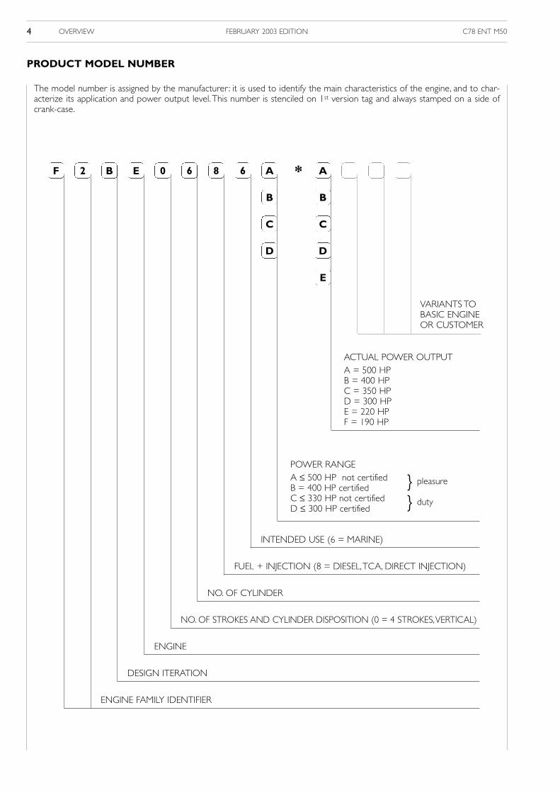
The model number is assigned by the manufacturer : it is used to identify the main characteristics of the engine, and to char-acterize its application and power output level.This number is stenciled on 1st version tag and always stamped on a side ofcrank-case.
PRODUCT MODEL NUMBER
F 2 B E 0 6 8 6 A
B
C
D
* A
B
C
D
E
ENGINE FAMILY IDENTIFIER
DESIGN ITERATION
ENGINE
NO. OF STROKES AND CYLINDER DISPOSITION (0 = 4 STROKES,VERTICAL)
NO. OF CYLINDER
FUEL + INJECTION (8 = DIESEL,TCA, DIRECT INJECTION)
INTENDED USE (6 = MARINE)
POWER RANGEA ≤ 500 HP not certified B = 400 HP certifiedC ≤ 330 HP not certifiedD ≤ 300 HP certified
ACTUAL POWER OUTPUTA = 500 HPB = 400 HPC = 350 HPD = 300 HPE = 220 HPF = 190 HP
VARIANTS TOBASIC ENGINE OR CUSTOMER
duty
pleasure
C78 ENT M50 OVERVIEW 5FEBRUARY 2003 EDITION
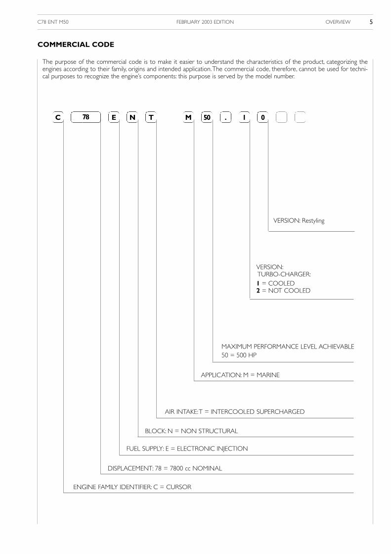
The purpose of the commercial code is to make it easier to understand the characteristics of the product, categorizing theengines according to their family, origins and intended application.The commercial code, therefore, cannot be used for techni-cal purposes to recognize the engine’s components: this purpose is served by the model number.
COMMERCIAL CODE
C 78 E N T M 50 . 1 0
ENGINE FAMILY IDENTIFIER: C = CURSOR
DISPLACEMENT: 78 = 7800 cc NOMINAL
FUEL SUPPLY: E = ELECTRONIC INJECTION
BLOCK: N = NON STRUCTURAL
AIR INTAKE:T = INTERCOOLED SUPERCHARGED
APPLICATION: M = MARINE
MAXIMUM PERFORMANCE LEVEL ACHIEVABLE50 = 500 HP
VERSION:TURBO-CHARGER:1 = COOLED2 = NOT COOLED
VERSION: Restyling
C78 ENT M50OVERVIEW6 FEBRUARY 2003 EDITION
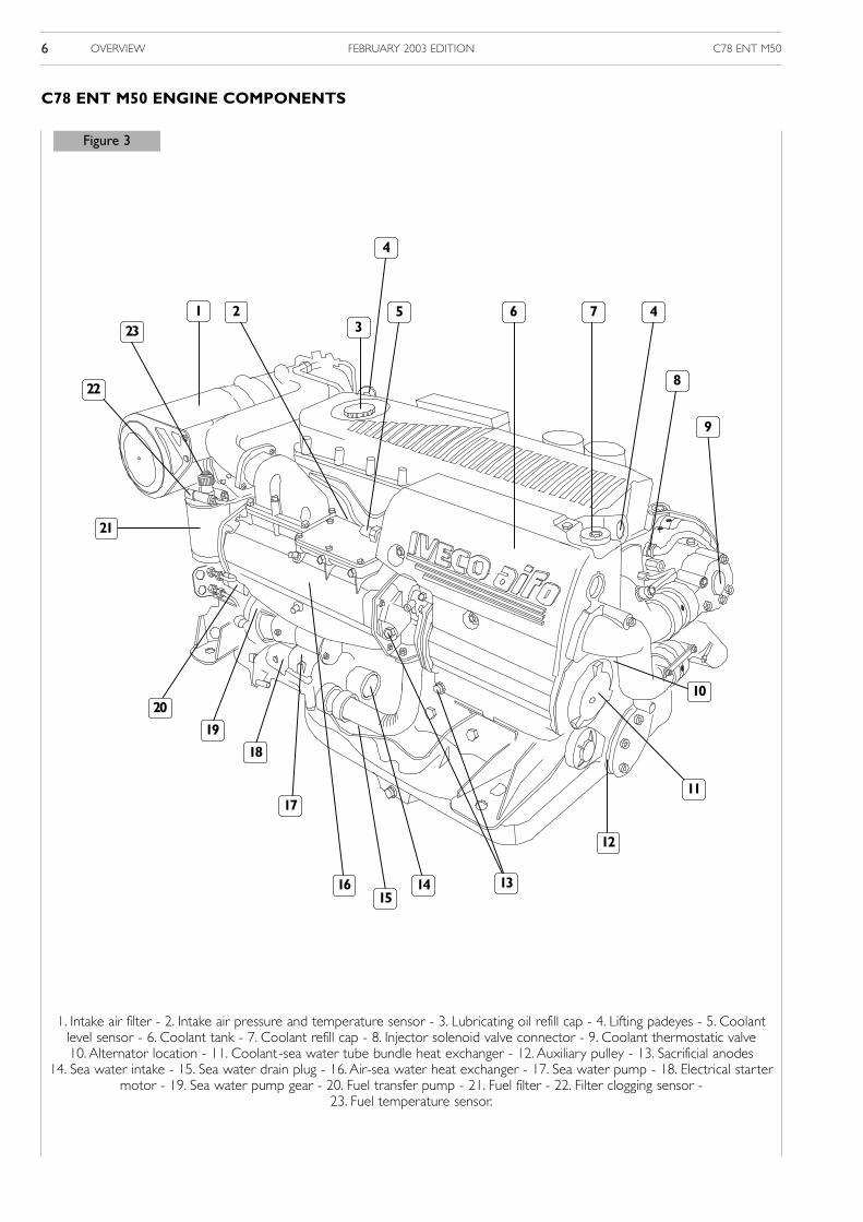
Figure 3
C78 ENT M50 ENGINE COMPONENTS
1. Intake air filter - 2. Intake air pressure and temperature sensor - 3. Lubricating oil refill cap - 4. Lifting padeyes - 5. Coolantlevel sensor - 6. Coolant tank - 7. Coolant refill cap - 8. Injector solenoid valve connector - 9. Coolant thermostatic valve10. Alternator location - 11. Coolant-sea water tube bundle heat exchanger - 12. Auxiliary pulley - 13. Sacrificial anodes
14. Sea water intake - 15. Sea water drain plug - 16. Air-sea water heat exchanger - 17. Sea water pump - 18. Electrical startermotor - 19. Sea water pump gear - 20. Fuel transfer pump - 21. Fuel filter - 22. Filter clogging sensor -
23. Fuel temperature sensor.
23
22
2 5 7
4
4
8
9
10
11
13
17
18
19
20
141615
12
21
13
6
C78 ENT M50 OVERVIEW 7FEBRUARY 2003 EDITION
Figure 4
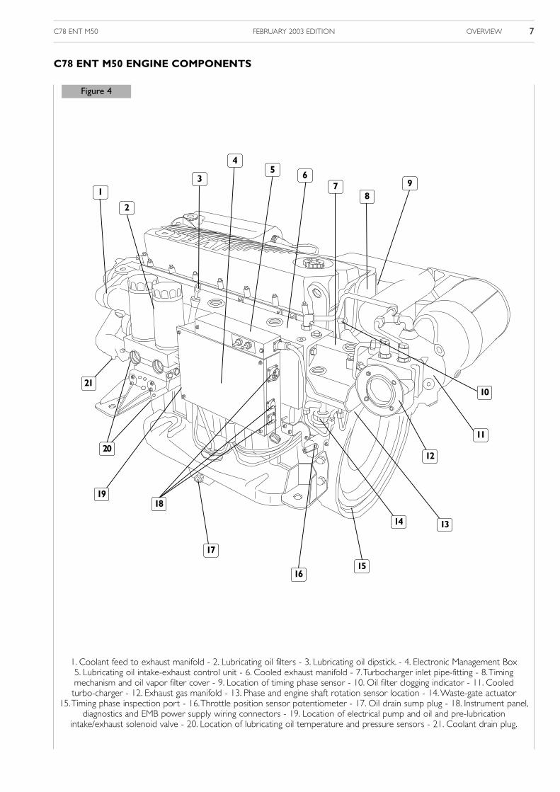
C78 ENT M50 ENGINE COMPONENTS
1. Coolant feed to exhaust manifold - 2. Lubricating oil filters - 3. Lubricating oil dipstick. - 4. Electronic Management Box5. Lubricating oil intake-exhaust control unit - 6. Cooled exhaust manifold - 7.Turbocharger inlet pipe-fitting - 8.Timing mechanism and oil vapor filter cover - 9. Location of timing phase sensor - 10. Oil filter clogging indicator - 11. Cooled turbo-charger - 12. Exhaust gas manifold - 13. Phase and engine shaft rotation sensor location - 14.Waste-gate actuator
15.Timing phase inspection port - 16.Throttle position sensor potentiometer - 17. Oil drain sump plug - 18. Instrument panel,diagnostics and EMB power supply wiring connectors - 19. Location of electrical pump and oil and pre-lubrication
intake/exhaust solenoid valve - 20. Location of lubricating oil temperature and pressure sensors - 21. Coolant drain plug.
1
21
3
45 6
78
9
10
11
12
1314
1516
17
1819
20
2

C78 ENT M50OVERVIEW8 FEBRUARY 2003 EDITION
Brake horsepower values in accordance with ISO 3046-1, attainable after about 50 hours of operation under reference envi-ronmental conditions characterized by 750 mmHg, 25°C, 30% relative humidity.Values fall within a tolerance of 5%.
Short range pleasure service (A1)Type of boatPleasure and military boats with planing hull for high speed or semi-planing and displacing pleasure hulls that use maximumpower for short periods alternating with prolonged periods at lower than maximum speed.
Engine utilizationUse of maximum power limited to 10% of the time. Cruising speed at engine rpm < 90% of nominal calibration rpm. Operatinglimit: 300 hours/year. Definition of calibrations and operating limits for military and government agencies according to contrac-tual specifications.
Nominal maximum power kW (HP) @ rpm 368 (500) @ 2600
Nominal maximum torque Nm (kgm) @ rpm 1500 (153) @ 1600÷2200
Long range pleasure service (A2)Type of boatPleasure and military boats with planing hull for high speed or semi-planing and displacing pleasure hulls that use maximumpower for short periods alternating with prolonged periods at lower than maximum speed.
Engine utilizationUse of maximum power limited to 10% of the time. Cruising speed at engine rpm < 90% of nominal calibration rpm. Operatinglimit: 1000 hours/year. Definition of calibrations and operating limits for military and government agencies according to con-tractual specifications.
Nominal maximum power kW (HP) @ rpm 330 (450) @ 2600
Nominal maximum torque Nm (kgm) @ rpm -
Light service (B)Type of boatLight boats for tourism, professional, or military use, with frequent speed changes. E.g.: pleasure boats, chartering, light passen-ger boats, high speed patrol boats for police, emergency, rescue, and special operations uses.
Engine utilizationUse of maximum power limited to 10% of the time. Cruising speed at engine rpm < 90% of nominal calibration rpm. Operatinglimit: 1,000 hours/year. Definition of calibrations and operating limits for military and government agencies according to con-tractual specifications.
Nominal maximum power kW (HP) @ rpm 294 (400) @ 2600
Nominal maximum torque Nm (kgm) @ rpm 1400 (143) @ 1600÷1800
Intermediate service (C)Type of boatLight boats for commercial, military, work and light fishing uses with variable speed. E.g.: patrol boats, pilot boats, light fishing ves-sels, water taxies, medium range seasonal passenger transport, fire-fighting.
Engine utilizationUse of maximum power limited to 25% of the time. Cruising speed at engine rpm < 90% of nominal calibration rpm. Operatinglimit: 1,000 ÷ 3,000 hours/year. Definition of calibrations and operating limits for military and government agencies accordingto contractual specifications.
Nominal maximum power kW (HP) @ rpm 258 (350) @2600
Nominal maximum torque Nm (kgm) @ rpm 1180 (120) @1600÷2200
PERFORMANCE

C78 ENT M50 OVERVIEW 9FEBRUARY 2003 EDITION
Fuel economy – Pleasure use (A1)
Specific fuel consumption at maximum power g/kWh (g/HPh) @ rpm ≤ 218 (≤ 160) @ 2600
Specific fuel consumption at maximum torque g/kWh (g/HPh) @ rpm ≤ 200 (≤ 147) @ 1800
Lubricating oil consumption at maximum power g/h @ rpm ≤ 240 @ 2600
Gas Emissions
Compliance with Standard IMO MARPOL 73/78ADDENDUM DIR. 94/25/EC
Sound Emissions
Maximum value of average levelfor engines in basic configuration dB@A (measurement standard) 95 (ISO 3744)
Power Takeoffs (Optional)
3- throated Front Pulley for V belts
Basic diameter mm 202
Throat size mm 10
Power available to each belt kW (HP) ≤ 7,4 (≤ 10)
3-throated Front Pulley + Elastic Joint for Flange Coupling
Available torque Nm (kgm) ≤ 500 (≤ 51)
3-throated Front Pulley + Elastic Joint for Shaft Coupling
Available torque Nm (kgm) ≤ 400 (≤ 40,8)
C78 ENT M50OVERVIEW10 FEBRUARY 2003 EDITION
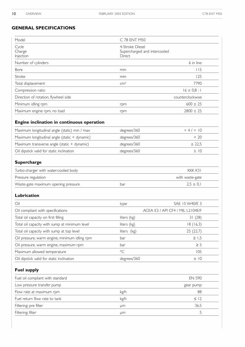
Model C 78 ENT M50
Cycle 4-Stroke DieselCharge Supercharged and intercooledInjection Direct
Number of cylinders 6 in line
Bore mm 115
Stroke mm 125
Total displacement cm3 7790
Compression ratio 16 ± 0,8 : 1
Direction of rotation, flywheel side counterclockwise
Minimum idling rpm rpm 600 ± 25
Maximum engine rpm, no load rpm 2800 ± 25
Engine inclination in continuous operation
Maximum longitudinal angle (static) min / max degrees/360 + 4 / + 10
Maximum longitudinal angle (static + dynamic) degrees/360 + 20
Maximum transverse angle (static + dynamic) degrees/360 ± 22,5
Oil dipstick valid for static inclination degrees/360 ± 10
Supercharge
Turbo-charger with water-cooled body KKK K31
Pressure regulation with waste-gate
Waste-gate maximum opening pressure bar 2,5 ± 0,1
Lubrication
Oil type SAE 15 W40/E 3
Oil compliant with specifications ACEA E3 / API CF4 / MIL L2104E/F
Total oil capacity on first filling liters (kg) 31 (28)
Total oil capacity with sump at minimum level liters (kg) 18 (16,3)
Total oil capacity with sump at top level liters (kg) 25 (22,7)
Oil pressure, warm engine, minimum idling rpm bar ≥ 1,5
Oil pressure, warm engine, maximum rpm bar ≥ 5
Maximum allowed temperature °C 105
Oil dipstick valid for static inclination degrees/360 ± 10
Fuel supply
Fuel oil compliant with standard EN 590
Low pressure transfer pump gear pump
Flow rate at maximum rpm kg/h 88
Fuel return flow rate to tank kg/h ≤ 12
Filtering: pre filter µm 36,5
Filtering: filter µm 5
GENERAL SPECIFICATIONS
C78 ENT M50 OVERVIEW 11FEBRUARY 2003 EDITION
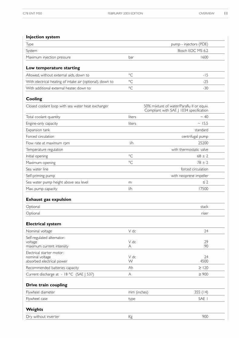
Injection system
Type pump - injectors (PDE)
System Bosch EDC MS 6.2
Maximum injection pressure bar 1600
Low temperature starting
Allowed, without external aids, down to °C -15
With electrical heating of intake air (optional), down to °C -25
With additional external heater, down to °C -30
Cooling
Closed coolant loop with sea water heat exchanger 50% mixture of water/Paraflu II or equiv.Compliant with SAE J 1034 specification
Total coolant quantity liters ~ 40
Engine-only capacity liters ~ 15,5
Expansion tank standard
Forced circulation centrifugal pump
Flow rate at maximum rpm l/h 25200
Temperature regulation with thermostatic valve
Initial opening °C 68 ± 2
Maximum opening °C 78 ± 2
Sea water line forced circulation
Self-priming pump with neoprene impeller
Sea water pump height above sea level m ≤ 2
Max. pump capacity l/h 17500
Exhaust gas expulsion
Optional stack
Optional riser
Electrical system
Nominal voltage V dc 24
Self-regulated alternator:voltage V dc 29maximum current intensity A 90
Electrical starter motor:nominal voltage V dc 24absorbed electrical power W 4500
Recommended batteries capacity Ah ≥ 120
Current discharge at - 18 °C (SAE J 537) A ≥ 900
Drive train coupling
Flywheel diameter mm (inches) 355 (14)
Flywheel case type SAE 1
Weights
Dry without inverter Kg 900
C78 ENT M50OVERVIEW12 FEBRUARY 2003 EDITION
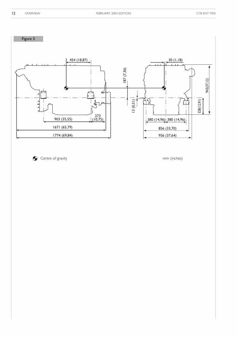
Figure 5
380 (14,96)
856 (33,70)
956 (37,64)
328(
12,9
1)
943(
37,1
2)
1774 (69,84)
1671 (65,79)
903 (35,55)273
(10,75) 380 (14,96)
13 (
0,51
)
187
(7,3
6)
454 (18,87) 30 (1,18)
mm (inches)Centre of gravity

C78 ENT M50 INSTALLATION INSTRUCTIONS 1FEBRUARY 2003 EDITION
SECTION 2
Installation Instructions
Page
INSTALLATION OVERVIEW 3
CAUTIONS 4
Handling cautions 4
Installation cautions 4
Engine’s first start 4
Use and servicing cautions 4
Prolonged engine inactivity 4
DESIGN STANDARDS 5
Accessibility 5
Securing 5
Engine intake and ventilation air 5
Sea water pipeline 5
Engine pre-heating 5
Exhaust gas 5
Starting aid 5
TECHNICAL DATA FOR INSTALLATION 6
FUEL LINE 7
Prefilter 7
Material characteristics 7
ELECTRICAL CIRCUIT 8
EMB 8
Power grid 10
Engine electrical ground 10
Battery recharge 11
Instrument and control panel 11
Instrument panel connection cable 11
Throttle position sensor 11
INSTALLATION TESTS 12
Lubricating oil fill 12
Fuel tank suction 12
Throttle position sensor 12
Pre-lubrication 12

C78 ENT M50INSTALLATION INSTRUCTIONS2 FEBRUARY 2003 EDITION
Page
First start 13
Fuel pressure in fuel supply line 14
Indication and control panel 14
EMB Electrical power supply 14
ECU temperature 14
Engine compartment vacuum 14
Engine compartment air temperature 14
Fuel temperature 14
Exhaust back-pressure 14
Exhaust temperature 14
PANEL WIRING 15
PREVENTIVE MAINTENANCE IN CASE OF PROLONGED ENGINE INACTIVITY 16
ENGINE’S FIRST START / RESTORING NORMAL OPERATING CONDITIONS 16

C78 ENT M50 INSTALLATION INSTRUCTIONS 3FEBRUARY 2003 EDITION
INSTALLATION OVERVIEW
1. Fuel tank with suction/return assembly. - 2. Electrical system cabinet - 3. Servo-throttle - 4. Instrument panel - 5.Throttlelever - 6. Engine and ventilation air intake - 7. Batteries - 8. Electronic Management Box (EMB) - 9.Ventilation air exhaust -
10. Sea water suction and decanting filter - 11. Exhaust gas and sea water drain pipe - 12. EMB power supply wiring -13. Indication and control panel wiring - 14. Linkage for throttle potentiometer operation - 15. Power grid wiring from
battery to generator/electrical starter motor - 16. Fuel tank feed and return pipe.
The figure shows the set of components of an installation including those supplied, as standard or optional items, with theengine equipment, and those supplied or built by the yard.The figure is meant to provide an overall picture of the operationsrequired for engine installation. Component positions and illustrations are not binding, but merely provided by way of indica-tion, and they depend on the choices made by yard engineers according to their competence, to the spaces and the prescrip-tions set out in the chapter that follows.
1 2 3
4 5
6
7
8
9
10
111213141516
Figure 1
81421

C78 ENT M50INSTALLATION INSTRUCTIONS4 FEBRUARY 2003 EDITION
CAUTIONS
Use and servicing- When starting the engine the first time, have available
appropriate means to shut off engine air intake in caseof runaway speed rate.
- Never disconnect the batteries electrically when theengine is running.
- Remove the batteries’ electrical connections before anyoperation on the electrical system.
- Ensure that battery terminals comply with the correctpolarity, that they are properly tightened and protectedagainst any short circuits and corrosion phenomena.
- Do not connect or disconnect electrical connectionson supplied circuits.
- Do not cause any sparks in the attempt to verify thepresence of electrical voltage.
- Do not draw fuel from tanks made of copper alloysand/or with pipes lacking filtering systems.
- Do not wash the engine and its components with cor-rosive or abrasive detergents, to avoid jeopardizing theoperating condition of the electrical connections.
Prolonged engine inactivityThe end of this section contains a list of the steps forpreparing the engine before long inactivity periods, and forrestoring it to its operating condition.
While an electronically controlled injection system providesfor better engine performance, it also makes it mandatoryfor installing and servicing personnel to comply with somefundamental rules that will surely become the norm as elec-tronic engine control equipment becomes ever more wide-spread.Boat fitters and servicing personnel are invited to familiar-ize themselves with the notes that follow and to contactIVECO Aifo personnel whenever compliance should proveimpossible.
Failure to comply with the rules set out below shall void the warranty and exonerate IVECO Aifo
from all liabilities.
HandlingThe engine shall be handled by experienced personnel,using the prescribed tool or an equalizer that will keep thelifting lines parallel and with suitable equipment in terms ofload bearing capacity and size.The two padeyes provided for lifting the engine alone shallalways be used simultaneously.
Installation- Use of switches or battery disconnects on the EMB
power supply line is not allowed.- Do not modify wiring; wire length cannot be changed.- Use only electronic device wiring compliant with the
IVECO standard, in terms of length, conductor type,location, clamping, shielding and grounding braids con-nection.
- To avoid any interference, the wiring for devices otherthan engine electronic systems must follow differentpaths.
- Do not connect any extraneous device to the engineelectrical equipment.
- Do not provide electrical voltage to the boat’s systembefore first verifying that there are no short circuits.
- Do not insert pipes for drawing fuel from the enginefuel supply pipelines.
- Do not make any modification to the engine’shydraulic circuits and components.
- Do not perform any electric arc welding operationswithout first removing the electronic units from theseat, placing them at a suitable distance for safety.
- Do not subject electronic units to temperaturesexceeding 80 °C.
- Do not paint electrical components and connections.- Do not alter the data contained in the engine control
unit.- Tighten threaded elements according to the prescri-
bed procedures and torque values.
Engine’s first startFollow the procedure set out in the paragraph entitled"Engine’s first start / Restoring normal operating conditions"at the end of this section.

C78 ENT M50 INSTALLATION INSTRUCTIONS 5FEBRUARY 2003 EDITION
DESIGN STANDARDS
Starting aidWhen the engine is to be used at temperatures lower than-15 °C, an electrical grid heater is installed. Its operation iscontrolled by the electronic unit of the injection system.Theelement will be placed between the turbocharger and theair-water heater exchanger (after-cooler), replacing the ter-minal part of the intake duct. Connection to the electricalwiring provided is achieved interposing a specific relay andconnection to the power supply grid.For use at temperatures lower than -25 °C, adoption of anauxiliary preheating system is recommended.
1. Specific junction pipe2. Electrical grid heater
3. Power relay
(1) The EDC electronic engine control is programmed toreduce maximum power output whenever the operatingparameters measured by the sensors indicate that criticalconditions have been reached which, if exceeded, wouldlead to the risk of damaging the engine.
Accessibility The engine shall be located in such a way as to allow to refilland drain engine fluids as required by servicing ope-rationsand to provide, even when underway, for easy access toelectrical fuses and to the diagnostics push-buttons withinthe EMB.Note that the lower part of the flywheel case has an inspec-tion port, useful when phasing the engine references of theinjection systems, and a window flanked with threadedholes, needed for fastening the “flywheel rotator” tool. Ifraised limber boards are installed in the engine room, theseprovisions may no longer be accessible to servicing person-nel. In this case, the phasing operation can be carried outusing a procedure that is typical of the marine applicationand described in the “OVERHAUL” section of the “Technicaland Repair Manual”; use of the tool to rotate the flywheel,however, will be impossible.
Securing Securing shall be accomplished by means of elastic blocksable to support the engine’s mass and the longitudinalthrust exerted by the propeller shaft when in motion.Dimension and fastening information is provided in the“Installation Diagram”.
Engine intake and ventilation AirCompliance with prescriptions on the quantity of air neces-sary for combustion and ventilation assures regular engineoperation even under adverse conditions and allows theengine to reach its maximum design power output. (1)
Sea water pipelineIt shall be provided with an inlet suitable for preventingextraneous bodies from entering the intake pipe. Betweenthe inlet and the pump it is advisable to place a gate, to beclosed in case of emergency or for extended stops, and afilter to hold the smaller impurities; it is also advisable toinstall a suitably sized, easily replaced zinc anode.The engine sea water pipeline is fitted by the manufacturerwith protective anodes to be replaced periodically (see“OVERVIEW” section).The rubber hoses positioned along the pipeline shall be suf-ficiently rigid to avoid creating choke points due to pinching.(1)
Engine pre-heatingIn case of usage requiring maximum power output immedi-ately, installation of an auxiliary pre-heater on the closedcooling loop is recommended.
Exhaust gasThe exhaust fume discharge pipeline shall be positioned incompliance with the indications contained in the IVECOAifo Publication “Marine Engine Installation Manual”, whichalso provides indications to design the exhaust pipeline.
Figure 2
1
2
3
80829
C78 ENT M50INSTALLATION INSTRUCTIONS6 FEBRUARY 2003 EDITION
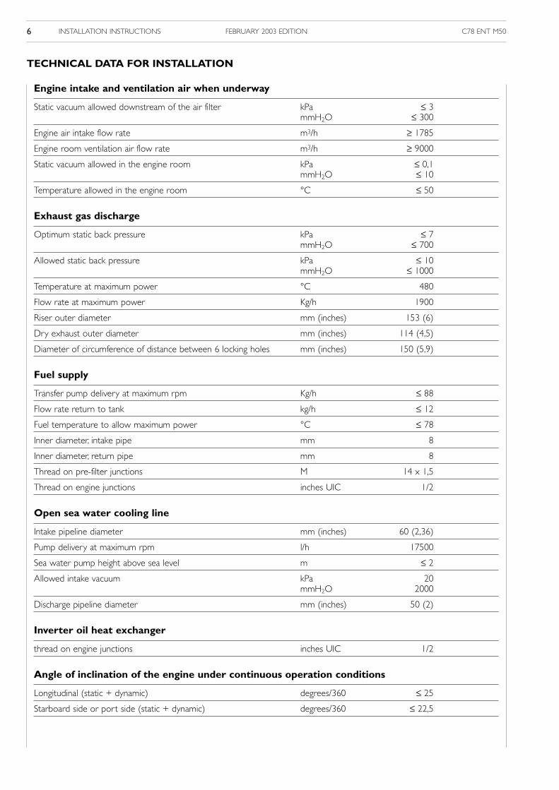
TECHNICAL DATA FOR INSTALLATION
Engine intake and ventilation air when underway
Static vacuum allowed downstream of the air filter kPa ≤ 3mmH2O ≤ 300
Engine air intake flow rate m3/h ≥ 1785
Engine room ventilation air flow rate m3/h ≥ 9000
Static vacuum allowed in the engine room kPa ≤ 0,1mmH2O ≤ 10
Temperature allowed in the engine room °C ≤ 50
Exhaust gas discharge
Optimum static back pressure kPa ≤ 7mmH2O ≤ 700
Allowed static back pressure kPa ≤ 10mmH2O ≤ 1000
Temperature at maximum power °C 480
Flow rate at maximum power Kg/h 1900
Riser outer diameter mm (inches) 153 (6)
Dry exhaust outer diameter mm (inches) 114 (4,5)
Diameter of circumference of distance between 6 locking holes mm (inches) 150 (5,9)
Fuel supply
Transfer pump delivery at maximum rpm Kg/h ≤ 88
Flow rate return to tank kg/h ≤ 12
Fuel temperature to allow maximum power °C ≤ 78
Inner diameter, intake pipe mm 8
Inner diameter, return pipe mm 8
Thread on pre-filter junctions M 14 x 1,5
Thread on engine junctions inches UIC 1/2
Open sea water cooling line
Intake pipeline diameter mm (inches) 60 (2,36)
Pump delivery at maximum rpm l/h 17500
Sea water pump height above sea level m ≤ 2
Allowed intake vacuum kPa 20mmH2O 2000
Discharge pipeline diameter mm (inches) 50 (2)
Inverter oil heat exchanger
thread on engine junctions inches UIC 1/2
Angle of inclination of the engine under continuous operation conditions
Longitudinal (static + dynamic) degrees/360 ≤ 25
Starboard side or port side (static + dynamic) degrees/360 ≤ 22,5

C78 ENT M50 INSTALLATION INSTRUCTIONS 7FEBRUARY 2003 EDITION
FUEL LINE
charges.The tank shall be provided with a vent to preventinternal pressure from exceeding ± 5kPa (± 0.5 mmH2O).Fuel tank and suction assembly shall be so shaped as toassure suction even at the maximum longitudinal and trans-verse inclination allowed for the boat, with a residual quan-tity of fuel oil considered “reserves”.It is recommended to obtain a residual capacity on the bot-tom of the tank, where the intake inlet should be posi-tioned, and to use a Venturi inlet cup to prevent the entryof sludge.The return flow must take place in such a way asto favor the mixing of returning fuel oil with the fuel oil inthe tank.Use of metallic pipes, except those made of copper or itsalloys, shall entail connecting each individual segment to theengine ground or battery negative terminal to prevent theaccumulation of electrostatic discharges, and inserting avibration damping elastic junction on each segment.Installed pipes shall be CE certified.
Pre-filterThe pre-filter with priming pump, supplied separate fromthe engine, must be adequately fastened in such a way as toenable easily to replace the filtering cartridge and/or tooperate the pump.To avoid introducing impurities in the feeding pipelinesinside the engine, we recommend not installing filtering car-tridges previously filled with fuel in the system.
Material CharacteristicsThe fuel tank, the suction and return assembly and the feedpipes shall withstand the continuous abrasion caused by a90 l/h flow of fuel oil at a temperature of 80 °C withoutnoticeable warping, wear, or release of material.Use of metallic materials, though not copper alloys, isallowed provided they are connected to the battery’s neg-ative terminal to avoid the accumulation of electrostatic dis-
1. From the tank - 2. Sensor for detecting the presence of water in the filter - 3. Decanting filter - 4.Priming pump - 5. Fuel inlet junction - 6. Fuel return junction to tank - 7. Gear pump - 8. Junctions for inverter oil heat exchanger.
Figure 3
3
1
8
7
2
65
4
81795

C78 ENT M50INSTALLATION INSTRUCTIONS8 FEBRUARY 2003 EDITION
ELECTRICAL CIRCUIT
Electrically insulate the container, if secured to a metal bulk-head, to avoid the onset of parasite currents, and connect itto the negative terminal of the battery. The position mustallow for easy access to the fuses and the diagnosing push-buttons contained in it, even when underway. No modifica-tion is allowed to the wiring.
EMB (Electronic Management Box) This is the housing for the electrical and electronic unitsmanaging and controlling the engine’s operation. It is sup-plied fastened to the engine in such a position as to allowfor an easy access to the electrical components. If it is nec-essary to position it differently, fasten it in the vertical posi-tion with the wire bundles to the engine projecting down-wards and at such a distance that no modifications to theengine wiring are required.
GENERAL NOTESDO NOT USE wiring belonging to the engine’s electrical equipment to supply power to other devices in the boat.PLACE engine electrical wiring independently from the other wiring installed on the boat.USE of switches or battery disconnects on the EMB power supply line is not allowed.EXTREME CARE SHOULD BE PLACED in the polarization of the electrical connections and in the correct coupling of theirlocking elements.
1. EDC system electronic control unit - 2. ECU B connector - 3. Pre-lubrication control unit - 4. Electrical pre-lubricationpump intake/exhaust enabling control - 5. Pre-lubrication/engine oil replacement solenoid valve enabling control -
6. G connector for instrument panel wiring - 7. Fitting for negative polarity – electrical ground connections - 8. Q connectorfor diagnostic instrument connection - 9. H connector for power supply grid wiring - 10. Grid heater relay - 11. Alternatorexcitation resistor - 12. Engine electrical wiring and throttle potentiometer - 13. Location of blink-code push-button and
indicator light - 14. Relay and fuse box - 15. ECU A connector.
Figure 4
1 23 4 5
6
7
8
9
101112
13
1415
81422
C78 ENT M50 INSTALLATION INSTRUCTIONS 9FEBRUARY 2003 EDITION
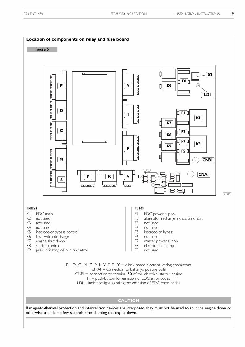
FusesF1 EDC power supplyF2 alternator recharge indication circuitF3 not usedF4 not usedF5 intercooler bypassF6 not usedF7 master power supplyF8 electrical oil pumpF9 not used
RelaysK1 EDC mainK2 not usedK3 not usedK4 not usedK5 intercooler bypass controlK6 key switch dischargeK7 engine shut downK8 starter controlK9 pre-lubricating oil pump control
E
D
C
M
Z
Y K9
K7
K6
K5 K8
K1
F7
F5
F2
F1
F8
T
F
VKP
S2
LD1
CNB1
Figure 5
CNA1
E – D- C- M- Z- P- K- V- F- T –Y = wire / board electrical wiring connectorsCNAI = connection to battery’s positive pole
CNBI = connection to terminal 50 of the electrical starter enginePI = push-button for emission of EDC error codes
LDI = indicator light signaling the emission of EDC error codes
Location of components on relay and fuse board
81423
CAUTION
If magneto-thermal protection and intervention devices are interposed, they must not be used to shut the engine down orotherwise used just a few seconds after shutting the engine down.
C78 ENT M50INSTALLATION INSTRUCTIONS10 FEBRUARY 2003 EDITION
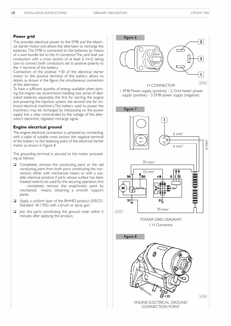
Power gridThis provides electrical power to the EMB and the electri-cal starter motor and allows the alternator to recharge thebatteries. The EMB is connected to the batteries by meansof a wire bundle led to the H connector.The yard shall useconductors with a cross section of at least 6 mm2 takingcare to connect both conductors set to positive polarity tothe + terminal of the battery.Connection of the positive +30 of the electrical startermotor to the positive terminal of the battery allows toobtain, as shown in the figure, the simultaneous connectionof the alternator.To have a sufficient quantity of energy available when start-ing the engine, we recommend installing two series of ded-icated batteries separately, the first for starting the engineand powering the injection system, the second one for on-board electrical machinery.The battery used to power themachinery may be recharged by interposing on the powersupply line a relay commanded by the voltage of the alter-nator’s electronic regulator recharge signal.
Engine electrical groundThe engine electrical connection is achieved by connecting,with a cable of suitable cross section, the negative terminalof the battery to the fastening point of the electrical startermotor as shown in Figure 8.
The grounding terminal is secured to the motor proceed-ing as follows:
Completely remove the conducting paint or the oldconducting paint from both parts constituting the con-nection, either with mechanical means or with a suit-able chemical product; if parts whose surface has beentreated need to be used for the securing operation, first
completely remove the anaphoretic paint bymechanical means, obtaining a smooth supportplane;
Apply a uniform layer of the BH44D product (IVECOStandard 18-1705) with a brush or spray gun;
Join the parts constituting the ground node within 5minutes after applying the product.
Figure 8
POWER GRID DIAGRAM1. H Connector.
ENGINE ELECTRICAL GROUND CONNECTION POINT
70 mm2
10 mm2
6 mm2
6 mm2
6 m
m2
70 mm2
H CONNECTOR1. EMB Power supply (positive) - 2. Grid heater power
supply (positive) - 3. EMB power supply (negative).
3
1
2
81424
81425
81789
Figure 6
Figure 7
1

C78 ENT M50 INSTALLATION INSTRUCTIONS 11FEBRUARY 2003 EDITION
Battery rechargeThe electronic regulator of the alternator supplied with theengine can effectively control battery recharge through the Sterminal of the three-pole connector.For reasons related to the test bench testing phase, this ter-minal’s line is connected to the positive polarity of the elec-trical system, meeting the need to control the recharge ofbatteries located near the engine.If different installation needs require to connect the batteriesfar from the engine, we recommend changing this connec-tion, cabling the line relating to the S terminal of the alterna-tor directly to the positive terminal of the battery.
Instrument and control panel Supplied on request by IVECO Aifo, this is connected to theEMB with three different lengths of wiring as indicated in theitem that follows.Technical information and data for the manufacture of pan-els by the Yard must be requested from the IVECO Aifotechnical assistance service.
Connecting cable between the indicationpanel and the EMBSupplied by IVECO Aifo on request, it is available in 3 differ-ent lengths:
3 meters: Drawing 8031150
5 meters: Drawing 8031151
7 meters: Drawing 8031152
Throttle position sensorAfter testing the operating condition of the linkage, adjustthe stroke of servo components so that:
With the throttle at idle, the potentiometer rod is in theresting position and the safety switch inside is electrical-ly open.The test must be conducted with an ohmmeterbetween the points D and E of the potentiometer con-nector.With readings of:∞ Ω = optimal adjustment1 KΩ = the resting position requires better mechanicaladjustment, to bring the value back to ∞ Ω
With the throttle at the maximum rpm stop, the rod ofthe potentiometer is in the maximum travel position.
Technical notes for Yard wiring are provided at the end ofthis section.
Figure 9
CONNECTIONS TO THE REGULATOR
EMB TO PANEL CONNECTING CABLE
TESTING POTENTIOMETER ROD TRAVEL
Connect to positive terminal of the battery
Figure 10
Figure 11
81790
81792
81791B

C78 ENT M50INSTALLATION INSTRUCTIONS12 FEBRUARY 2003 EDITION
“Common sense” tests, such as exposing heat-sensitive partsto heat (plastic, wiring, electronic units, etc.….), and thosethat for years have characterized the quality of the work per-formed in yards, are not mentioned herein, although they areof the utmost importance.
Tests to verify the engine’s and the electronic control systemcomponents’ operating condition can be performed quicklyand with top reliability using specific diagnostic tools, availableto the IVECO Aifo Technical Assistance Centers.
Lubricating oil fillLubricating oil transfer operations are simplified by the pres-ence of an electrical control system. Manual controls fortransfer and pre-lubrication operations are positioned on theunit above the EMB. For safety reasons, controls are enabledonly with the key switch in the “OFF” position
Sequence1. Place the stable switch in the “ON” position, thus ener-
gizing the switching solenoid valve to place the empty-ing/filling junction in communication with the electricalpump and with the oil sump.
2. Use the intake/exhaust push-button to complete thedesired operation.
3. Place the stable switch back to the “OFF” position.
Fuel tank suction Check assembly suction at the maximum allowed longitudi-nal and transverse inclinations, with such a residual quantityin the tank as to cause the reserve indicator light to stay onpermanently.Verify the absence of air in the fuel feed pipeline, using a clearpipe placed, in inverted “U” fashion, before the engine inlet.
Throttle position sensorVerify, in the idling and maximum rpm positions, the correla-tion between the throttle on the bridge and the sensor rod,noting:
Whether, with the lever in the idle position, the switch inthe sensor is electrically open.
Whether in the maximum rpm position the sensor rodreaches the mechanical end stop.
Pre-lubricationThe task of pre-lubricating the engine’s internal componentsis managed and controlled by an electronic circuit of theEMB; the operation can also be conducted by acting manu-ally, with the key switch in the “OFF” position, only on the oilintake/exhaust push-button positioned on the related unit. Ifthe push-button is placed for a few seconds in the“EXHAUST” position, the filters and the internal engineducts will be filled.
INSTALLATION TESTS
1 2
ELECTRICAL LUBRICATING PUMP CONTROLS1. Oil intake/exhaust control.
2. Switching solenoid valve control.
PRE-LUBRICATION SYSTEM1. One way valve - 2. Switching solenoid valve
3. Electrical pump.
Figure 13
2
3
Figure 12
81422
80836
1
C78 ENT M50 INSTALLATION INSTRUCTIONS 13FEBRUARY 2003 EDITION
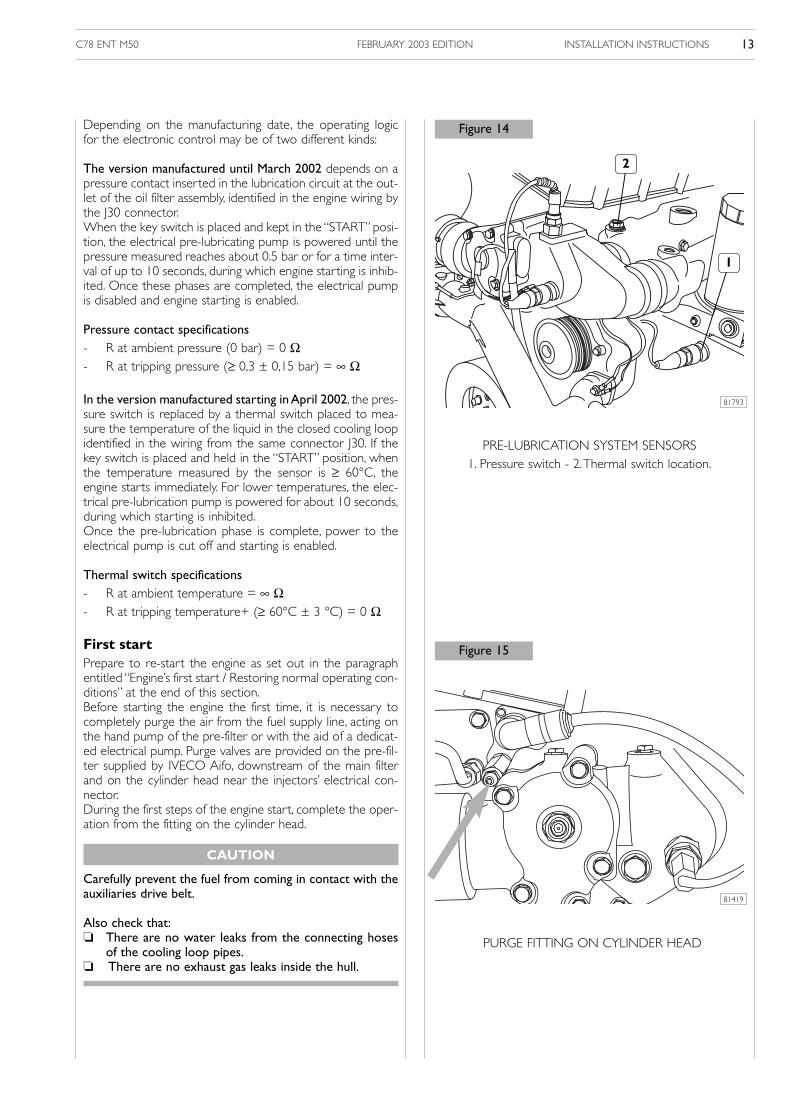
Depending on the manufacturing date, the operating logicfor the electronic control may be of two different kinds:
The version manufactured until March 2002 depends on apressure contact inserted in the lubrication circuit at the out-let of the oil filter assembly, identified in the engine wiring bythe J30 connector.When the key switch is placed and kept in the “START” posi-tion, the electrical pre-lubricating pump is powered until thepressure measured reaches about 0.5 bar or for a time inter-val of up to 10 seconds, during which engine starting is inhib-ited. Once these phases are completed, the electrical pumpis disabled and engine starting is enabled.
Pressure contact specifications- R at ambient pressure (0 bar) = 0 Ω- R at tripping pressure (≥ 0,3 ± 0,15 bar) = ∞ Ω
In the version manufactured starting in April 2002, the pres-sure switch is replaced by a thermal switch placed to mea-sure the temperature of the liquid in the closed cooling loopidentified in the wiring from the same connector J30. If thekey switch is placed and held in the “START” position, whenthe temperature measured by the sensor is ≥ 60°C, theengine starts immediately. For lower temperatures, the elec-trical pre-lubrication pump is powered for about 10 seconds,during which starting is inhibited.Once the pre-lubrication phase is complete, power to theelectrical pump is cut off and starting is enabled.
Thermal switch specifications- R at ambient temperature = ∞ Ω- R at tripping temperature+ (≥ 60°C ± 3 °C) = 0 Ω
First startPrepare to re-start the engine as set out in the paragraphentitled “Engine’s first start / Restoring normal operating con-ditions” at the end of this section.Before starting the engine the first time, it is necessary tocompletely purge the air from the fuel supply line, acting onthe hand pump of the pre-filter or with the aid of a dedicat-ed electrical pump. Purge valves are provided on the pre-fil-ter supplied by IVECO Aifo, downstream of the main filterand on the cylinder head near the injectors’ electrical con-nector.During the first steps of the engine start, complete the oper-ation from the fitting on the cylinder head.
CAUTION
Carefully prevent the fuel from coming in contact with theauxiliaries drive belt.
Also check that: There are no water leaks from the connecting hoses
of the cooling loop pipes. There are no exhaust gas leaks inside the hull.
PRE-LUBRICATION SYSTEM SENSORS1. Pressure switch - 2.Thermal switch location.
PURGE FITTING ON CYLINDER HEAD
1
2
Figure 14
Figure 15
81793
81419

C78 ENT M50INSTALLATION INSTRUCTIONS14 FEBRUARY 2003 EDITION
EMB electrical powerVerify whether the power supply voltage to the H connec-tor, with the engine idling, is no more than 0.4 V smaller thanthe battery voltage measured during the test.Shut the engine down, placing the key in the OFF position,and test whether the relay K 1 that powers the electronicengine control unit is de-energized after 2 ÷ 7 seconds
ECU temperatureCheck whether the temperature of the surface of the ele-ctronic engine control unit, after 30 minutes with the engineat maximum power output, is less than +80 °C.
Engine compartment vacuumVerify that ambient pressure in the engine room, with theengine at full load and maximum power output, complieswith the technical data set out herein.
Engine compartment air temperatureVerify that temperature in the engine room, after 30 minutesunderway with the engine at maximum power output, doesnot exceed 50°C, or +15°C over outside temperature.
Fuel temperatureVerify that temperature of the fuel in the transfer line, whileunderway at maximum power output and with a stablequantity of fuel in reserve does not exceed 80°C. A highervalue would lead to a reduction in engine performance dueto the safety strategies built in the electronic control unit. Ifthe fuel tends to reach the maximum allowed temperature,install a heat exchanger for the fuel.
Exhaust back-pressureVerify that the back pressure at the inlet of the exhaust gasduct, with the engine at full load and maximum power out-put, complies with the technical data set out herein.
Exhaust temperatureVerify that the temperature of the exhaust gas under maximum power conditions is close to the prescribed value.
Fuel pressure in fuel supply lineThe value of fuel pressure in the transfer loop must be mea-sured from the purge fitting on the cylinder head. We rec-ommend using a manometer with oil-damped needle andend-of-scale at 5 bar.The pressure measured with the engineidling must be about 3.5 bar and tend to rise slightly asengine rpm increases.
Instrument and control panelCheck the operation of all indicator lights simulating thebehavior of the sensors connected to them. To reset anyerrors that may be stored in the engine electronic controlunit, proceed as follows:
1. Shut the engine down, rotating the key switch to the“OFF” position.
2. While holding down the diagnosing push-button in theEMB, rotate the key switch to the “ON” position andkeep the diagnosing push-button down for at least 5seconds
3. Release the push-button and rotate the key switch backto the “OFF” position.
At the end of this procedure, the codes of any faults detect-ed during engine installation operations will be dele-ted fromthe ECU.To make sure that no fault data remains stored init, and also that there are no additional faults in the system,proceed as follows:
1. Rotate the key switch to the “ON” position.
2. Press the diagnosing push-button making sure that, afterit briefly lights up as a test, the flashing code indicatorlight remains off.
If the ECU detects the presence of errors or operatinganomalies, the indicator light will emit the code of the firststored error with two series of flashes of different frequen-cy; after a few seconds have elapsed from the end of theemission, the codes of any subsequent errors will be emittedif the push-button is pressed again.The repetition of the firstof the emitted code will indicate that all information con-tained in the memory have been emitted.Such an event will require a review of the installation, inorder to remove the cause of the error or of the anomaly.The table containing the explanation of each code is provided in the “DIAGNOSTICS” section.
C78 ENT M50 INSTALLATION INSTRUCTIONS 15FEBRUARY 2003 EDITION
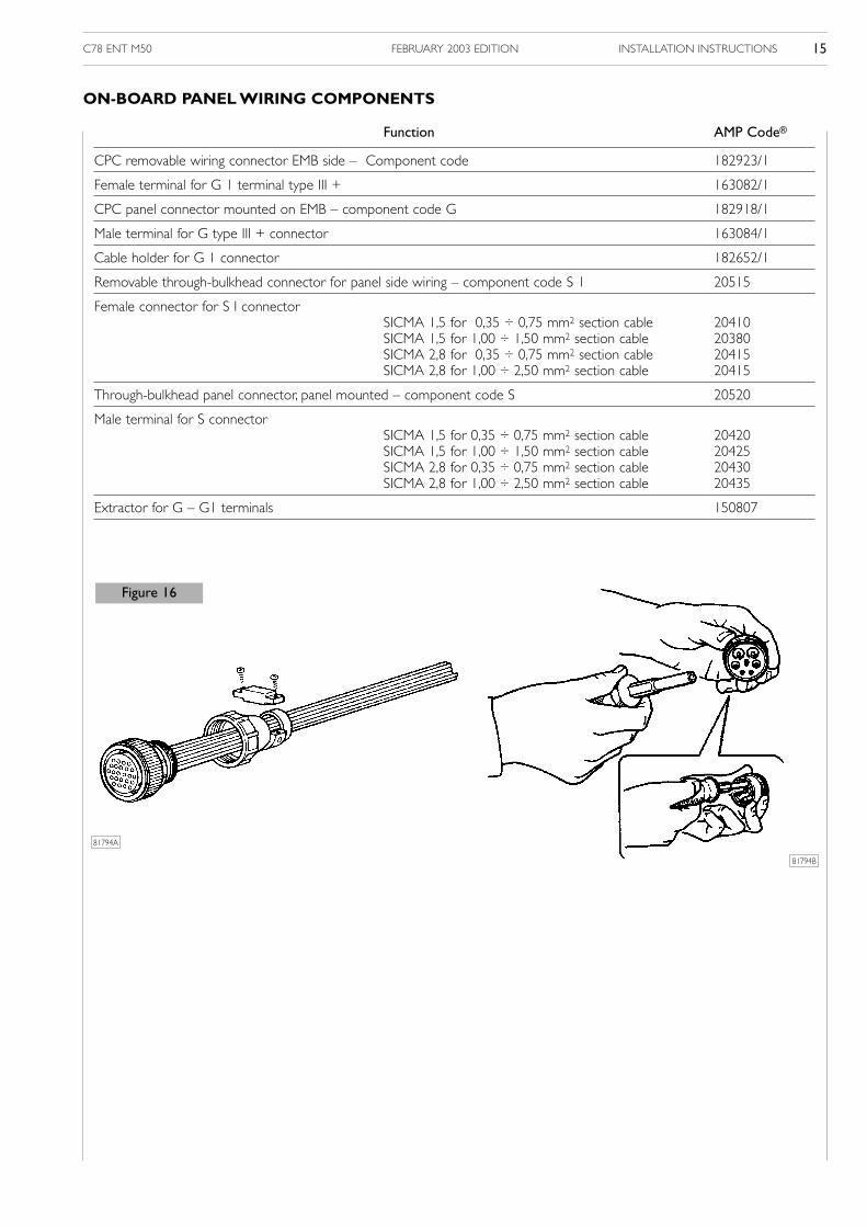
ON-BOARD PANEL WIRING COMPONENTS
Function AMP Code®
CPC removable wiring connector EMB side – Component code 182923/1
Female terminal for G 1 terminal type III + 163082/1
CPC panel connector mounted on EMB – component code G 182918/1
Male terminal for G type III + connector 163084/1
Cable holder for G 1 connector 182652/1
Removable through-bulkhead connector for panel side wiring – component code S 1 20515
Female connector for S I connectorSICMA 1,5 for 0,35 ÷ 0,75 mm2 section cable 20410SICMA 1,5 for 1,00 ÷ 1,50 mm2 section cable 20380SICMA 2,8 for 0,35 ÷ 0,75 mm2 section cable 20415SICMA 2,8 for 1,00 ÷ 2,50 mm2 section cable 20415
Through-bulkhead panel connector, panel mounted – component code S 20520
Male terminal for S connectorSICMA 1,5 for 0,35 ÷ 0,75 mm2 section cable 20420SICMA 1,5 for 1,00 ÷ 1,50 mm2 section cable 20425SICMA 2,8 for 0,35 ÷ 0,75 mm2 section cable 20430SICMA 2,8 for 1,00 ÷ 2,50 mm2 section cable 20435
Extractor for G – G1 terminals 150807
Figure 16
81794B
81794A

C78 ENT M50INSTALLATION INSTRUCTIONS16 FEBRUARY 2003 EDITION
PREVENTIVE MAINTENANCE IN CASE OF PROLONGED ENGINE INACTIVITY
ENGINE’S FIRST START / RESTORINGNORMAL OPERATING CONDITIONS
To prevent oxidation to the inner parts of the engine andsome components of the injection system, if periods of inac-tivity exceeding two months are expected, the engine mustbe prepared every six months by proceeding as follows:
1. Drain the lubricating oil from the sump, after heating theengine.
2. Fill the engine with protective oil type 30/M (or MIL2160B type 2) up to the “minimum” level indicated onthe dipstick.Start the engine and let it run for about 5 minutes.
3. Drain the fuel from the injection line, from the filter andfrom the ducts in the cylinder heads.To do so, loosen thedrain cap in the front part of the cylinder head and thefuel inlet junction with the cylinder head, taking care toprevent the fuel from coming in contact with the auxil-iaries belt. See “First start” paragraph at page 13 in thissection.
4. Connect the fuel line with a tank containing CFB pro-tective liquid (ISO 4113) and let the liquid enter the bypressurizing the line and turning the engine over forabout 2 minutes, after excluding the operation of theinjection system. The required operation can be com-pleted by directly polarizing the terminal 50 of the elec-tric starter motor with 24V positive voltage, by means ofa conductor prepared for the occasion.
5. Nebulize about 80 g (10 g per liter of displacement) ofprotective oil type 30/M into the intake mouth of theturbocharger, while turning the engine over as describedin the previous paragraph.
6. Close all the engine’s intake, exhaust, aeration and ventports with appropriate caps or seal with adhesive tape.
7. Drain from the oil sump the residual protective oil type30/M, which may be reused for 2 more engine lay-ups.
8. Apply tags bearing the inscription “ENGINE WITHOUTLUBE OIL” on the engine and on the panel.
9. Drain the cooling liquid if it is not mixed with anticorro-sive substances.
If exterior parts of the engines are to be protected as well,spray OVER 19 AR protective liquid on unpainted metalparts, such as flywheel, pulleys and others, taking care not tospray it on belts, connecting cables and electrical equipment.
1. Drain the residual protective oil type 30/M from thesump.
2. Pour lubricating oil into the engine, as provided by thespecifications and in the quantities set out in the Table ofRefills.
3. Drain the CFB protective liquid from the fuel line, com-pleting the operations set out in item 3 of “PREVENTIVEMAINTENANCE IN CASE OF PROLONGEDENGINE INACTIVITY”.
4. Remove the caps and/or the seals from the engine’sintake, exhaust, aeration and vent ports, restoring nor-mal operating conditions. Connect the turbochargerintake to the air filter.
5. Attach the fuel lines to the vessel’s fuel tank, completingthe operations set out in item 4 of “PREVENTIVEMAINTENANCE IN CASE OF PROLONGEDENGINE INACTIVITY”. During the filling operations,attach the fuel tank return pipe to a collecting containerto prevent residues of CFB protective liquid from flow-ing into the vessel’s fuel tank.
6. Verifiy the quantity of cooling liquid and refill as provid-ed by the specifications.
7. Start the engine and keep it running until idling speedhas completely stabilized.
8. Shut the engine down and delete the “errors” whichmay have been stored in the injection system ECU dur-ing the operation stabilization phases. For reset opera-tion, see “Blink code” paragraph at page 3 in the nextsection.
9. Remove the tags with the inscription “ENGINE WITH-OUT LUBE OIL” from the engine and from the panel.
C78 ENT M50 DIAGNOSTICS 1FEBRUARY 2003 EDITION
Diagnostics
Pagina
ECU BEHAVIOR 3
Fault indicator light 3
Blink code 3
Fault memory reset 3
Recovery 3
BLINK CODE TABLE 4
SECTION 3

C78 ENT M50DIAGNOSTICS2 FEBRUARY 2003 EDITION

C78 ENT M50 DIAGNOSTICS 3FEBRUARY 2003 EDITION
RecoveryAssociated to the detection of significant or severe faults,the ECU adopts strategies that, to allow safe use of theengine, limit some injection parameters within pre-setthresholds according to the severity of the situation.
As a result of these strategies, the engine’s maximum poweroutput is reduced. In case of intermittent faults, i.e. faultsthat are detected by the ECU and subsequently are nolonger present, performance reduction will be active untilthe engine is shut down.
Normal operation will be restored only at the subsequentstart-up, while the fault data will be “saved” in the faultmemory.
Fault Indicator LightThe ECU continuously monitors its own operating condi-tions as well as those of the components connected to itand of the engine itself, with complex self-diagnostics rou-tines. If faults are detected, the fault indicator light on theindications and control panel is lit in ways that provide aninitial indication of the severity of the problem.
Light off: no fault detected or minor fault that doesnot compromise operating safety.
Light on: significant fault, allowing to proceed to a diag-nostics center.
Blinking light: severe fault, requiring immediate servicing.If circumstances allow shutting the enginedown.
Blink codeThe emission of the fault codes detected by the self-diag-nostics routines and stored in the ECU starts after thepush-button located on the relay and fuse board is pressedand released.The LED to the side of the push-button andthe EDC indicator light on the indications and control panelwill simultaneously signal the codes by blinking two series ofemissions at different frequency, reproducing the digits indi-cating the fault with decimal numbering.
Slow blinking indicates the area of the fault (engine, injec-tors, …), fast blinking indicates a specific fault.
Every time the push-button is pressed and released, onlyone of the stored codes is emitted; therefore, the proce-dure needs to be repeated until the system emits the sameerror data as the first one: this will mean that the entire faultmemory has been analyzed.
If no anomalies are stored, the light comes on when thepush-button is pressed and comes off about 1 second afterit is released, without blinking.
Note:The blink code diagnostic procedure provides indica-tions about faults that are currently present but also aboutother faults, which arose in the past and are no longer pre-sent at the time of the diagnostic procedure.Therefore, it isabsolutely necessary, at the end of each servicing operation,to reset the error memory to prevent the system from sig-naling faults, in the future, whose cause has already beenremoved.
Fault memory resetIn current applications, the reset operation is carried outkeeping the blink code push-button pressed down with thekey switch in the OFF position and keeping it pressed for 5more seconds are setting the switch to ON. Confirmationof the reset will be obtained by turning the key switch fromOFF to ON and requesting blink codes again: at that point,no codes should be produced.
ECU BEHAVIOR

C78 ENT M50DIAGNOSTICS4 FEBRUARY 2003 EDITION
Blinking Code EDC Indicator light Indicated Fault
Control area
1.1 (on) not significant in marine applications
1.2 (on) not significant in marine applications
1.3 (off) not significant in marine applications
1.4 on throttle position sensor
1.5 (off) not significant in marine applications
1.6 (on) not significant in marine applications
1.7 (off) not significant in marine applications
Engine area
2.1 off coolant temperature sensor
2.2 off intake air temperature sensor
2.3 off fuel temperature sensor
2.4 on supercharge air pressure sensor
2.5 off ambient pressure sensor (inside the unit)
2.6 (on) not significant in marine applications
3.5 off battery voltage
Injectors
5.1 on cylinder 1 injector fault
5.2 on cylinder 2 injector fault
5.3 on cylinder 3 injector fault
5.4 on cylinder 4 injector fault
5.5 on cylinder 5 injector fault
5.6 on cylinder 6 injector fault
Engine rpm sensor
6.1 on flywheel sensor
6.2 on timing system sensor
6.4 blinking runaway engine
Electronic unit
9.1 blinking defective unit
9.2 on incorrect EEPROM data
9.3 (blinking) not significant in marine applications
9.4 on main relay
9.5 on erroneous engine shut-down procedure
9.6 on unit data storage operation not completed
BLINK CODE TABLE

C78 ENT M50 5FEBRUARY 2003 EDITION
NOTES

C78 ENT M506 FEBRUARY 2003 EDITION
NOTES

C78 ENT M50 7FEBRUARY 2003 EDITION

Iveco Aifo S.p.A.Viale Dell’Industria, 15/1720010 Pregnana Milanese - MI - (Italy)Tel. +39 02 93.51.01 - Fax +39 02 93.59.00.29www.iveco.com


