58
CCNA – Semester 3 Chapter 5 - Spanning Tree Protocol CCNA Exploration 4.0
| Date post: | 18-Nov-2014 |
| Category: |
Technology |
| Upload: | neo-kim |
| View: | 2,109 times |
| Download: | 0 times |

CCNA – Semester 3
Chapter 5 -
Spanning Tree Protocol
CCNA Exploration 4.0

2
Objectives
• Explain the role of redundancy in a converged
network
• Summarize how STP works to eliminate Layer 2
loops in a converged network
• Explain how the STP algorithm uses three steps to
converge on a loop-free topology
• Implement rapid per VLAN spanning tree (rapid
PVST+) in a LAN to prevent loops between redundant
switches.

3
Role of redundancy

4
Redundancy in a hierarchical network
• The hierarchical design model addresses issues found in the
flat model network topologies. One of the issues is
redundancy.
• Having multiple paths for data to traverse the network allows
for a single path to be disrupted without impacting the
connectivity of devices on the network.

5
Issues with Redundancy : Layer 2 Loop
• When multiple paths exist between two devices on the
network, a Layer 2 loop can occur.
• Ethernet frames do not have a time to live (TTL) like IP
packets traversing routers. So, if they are not terminated
properly on a switched network, they continue to bounce
from switch to switch endlessly.

6
Issues with Redundancy : Broadcast Storm
• A broadcast storm occurs when there are so many broadcast
frames caught in a Layer 2 loop that all available bandwidth
is consumed.
• As a result, no bandwidth is available bandwidth for
legitimate traffic, and the network becomes unavailable for
data communication.

7
Issues with Redundancy : Duplicate Unicast Frames
• Unicast frames sent onto a looped network can result in
duplicate frames arriving at the destination device.

8
Real-world redundancy issues
• Network loops that are a result of accidental duplicate
connections in the wiring closets are a common occurrence.
• The example displays a loop that occurs if a switch is
connected to two different switches on a network that are
both also interconnected. The impact of this type of loop is
much greater because it affects more switches directly.

9
The Spanning Tree Algorithm

10
Spanning Tree Protocol
• STP ensures that there is only one logical path between all
destinations on the network by intentionally blocking
redundant paths that could cause a loop.
• STP prevents loops from occurring by configuring a loop-free
path through the network using strategically placed blocking
state ports
• A port is considered
blocked when
network traffic is
prevented from
entering or leaving
that port

11
Spanning Tree Algorithm (STA)
• The STA designates a single switch as the root bridge and
uses it as the reference point for all path calculations.
• After the root bridge has been determined, the STA
calculates the shortest path to the root bridge. Each switch
uses the STA to determine which ports to block.

12
Spanning Tree Algorithm (STA) (cont)
• When the STA has determined which paths are to be left
available, it configures the switch ports into distinct port
roles.
– Root ports : Switch ports closest to the root bridge.
– Designated ports : All non-root ports that are still
permitted to forward traffic on the network.
– Non-designated ports :
All ports configured to be
in a blocking state to
prevent loops

13
Root Bridge & Election Process
• The root bridge serves as a reference point for all spanning-tree
calculations to determine which redundant paths to block.
• An election process determines which switch becomes the root
bridge.
1. After a switch boots, it sends out BPDU frames (more detail
later) containing the switch BID and the root ID every 2
seconds.
2. Initially, each switch identifies itself as the root bridge after
bootup.
3. If the root ID from the BPDU received is lower than the root ID on
the receiving switch, the receiving switch updates its root ID
identifying the adjacent switch as the root bridge
4. The switch then forwards new BPDU frames with the lower root
ID to the other adjacent switches.
5. Eventually, the switch with the lowest BID ends up being
identified as the root bridge for the spanning-tree instance.

14
Root Bridge & Election Process

15
Root Bridge & Election Process (cont)
• BID Structure
• Root Bridge

16
Best Path to the Route Bridge
• The path information is determined by summing up the
individual port costs along the path from the destination to
the root bridge.
• The default port costs are defined by the speed at which the
port operates.
• Although switch ports have a default port cost associated
with them, the port cost is configurable

17
Best Path to the Route Bridge (cont)
• Path cost is the sum of all the port costs along the path to
the root bridge.
• The paths with the lowest path cost become the preferred
path, and all other redundant paths are blocked.

18
Port Roles
• Root Port :
– The root port exists on non-root bridges and is the switch port with the best path to the root bridge. Root ports forward traffic toward the root bridge.
• Designated Port :
– For root bridges, all switch ports are designated ports.
– For non-root bridges, a designated port is the switch port that receives and forwards frames toward the root bridge as needed
– Only one designated port is allowed per segment
• Non-designated Port ;
– The non-designated port is a switch port that is blocked, so it is not forwarding data frames and not populating the MAC address table with source addresses
• Disabled Port :
– The disabled port is a switch port that is administratively shut down. A disabled port does not function in the spanning-tree process

19
Port Roles (cont)
• When determining the root port on a switch, the switch
compares the path costs on all switch ports participating in
the spanning tree.
• The switch port with the lowest overall path cost to the root is
automatically assigned the root port role because it is closest
to the root bridge.
• When there are two switch ports that have the same lowest
path cost to the root bridge, the switch uses the
customizable port priority value, or the lowest port ID if both
port priority values are the same.
• The port ID is the interface ID of the switch port.

20
Port Roles (cont) example

21
Port Roles (cont) example

22
Port Roles (cont) example
• After a switch determines which of its ports is the root port,
the remaining ports must be configured as either a
designated port (DP) or a non-designated port (non-DP)
• When two switches exchange their BPDU frames, they
examine the sending BID of the received BPDU frame to see
if it is lower than its own.
• The switch with the lower BID wins the competition and its
port is configured in the designated role. The losing switch
configures its switch port to be non-designated and,
therefore, in the blocking state to prevent the loop from
occurring.

23
Port Roles (cont) example

24
BPDU
• STP determines a root bridge for the spanning-tree instance
by exchanging BPDUs.
• BPDU Fields

25
BPDU (cont)
• By default, BPDU frames are sent every 2 seconds after a
switch is booted.
• When adjacent switches receive a BPDU frame, they
compare the root ID from the BPDU frame with the local root
ID.
– If the root ID in the BPDU is lower than the local root ID,
the switch updates the local root ID and the ID in its
BPDU messages
– If the local root ID is lower than the root ID received in the
BPDU frame, the BPDU frame is discarded.

26
BID
• The BID field of a BPDU frame contains three separate
fields: bridge priority, extended system ID, and MAC
address. Each field is used during the root bridge election.

27
BID (cont)

28
Port States and BPDU Timers
• To facilitate the learning of the logical spanning tree, each switch
port transitions through five possible port states and three BPDU
timers.

29
Port States and BPDU Timers (cont)
• Blocking - The port is a non-designated port and does not
participate in frame forwarding.
• Listening - In this state, the switch port is not only receiving
BPDU frames, it is also transmitting its own BPDU frames
and informing adjacent switches that the switch port is
preparing to participate in the active topology.
• Learning - The port prepares to participate in frame
forwarding and begins to populate the MAC address table.
• Forwarding - The port is considered part of the active
topology and forwards frames and also sends and receives
BPDU frames
• Disabled - The Layer 2 port does not participate in spanning
tree and does not forward frames.

30
Port States and BPDU Timers (cont)
• Cisco PortFast Technology
– When a switch port configured with PortFast is configured
as an access port, that port transitions from blocking to
forwarding state immediately, bypassing the typical STP
listening and learning states.

31
Port States and BPDU Timers (cont)

32
STP Topology Change
• A switch considers it has detected a topology change either
when a port that was forwarding is going down (blocking for
instance) or when a port transitions to forwarding and the
switch has a designated port.
• When a change is detected, the switch notifies the root
bridge of the spanning tree. The root bridge then broadcasts
the information into the whole network.

33
Cisco and STP Variants

34
Cisco and STP Variants

35
PVST +
• Cisco developed PVST+ so that a network can run an STP
instance for each VLAN in the network. With PVST+, more
than one trunk can block for a VLAN and load sharing can
be implemented.
• In a Cisco PVST+ environment, you can tune the spanning-
tree parameters so that half of the VLANs forward on each
uplink trunk

36
PVST + Bridge ID
• Bridge priority - A 4-bit field carries the bridge priority.
Because of the limited bit count, the priority is conveyed in
discrete values in increments of 4096. The default priority is
32,768.
• Extended system ID - A 12-bit field carrying the VID for
PVST+.
• MAC address - A 6-byte field with the MAC address of a
single switch.

37
Configure PVST +
• Step 1. Select the switches you want for the primary and secondary root
bridges for each VLAN.
• Step 2. Configure the switch to be a primary bridge for one VLAN, for
example switch S3 is a primary bridge for VLAN 20.
• Step 3. Configure the switch to be a secondary bridge for the other
VLAN, for example, switch S3 is a secondary bridge for VLAN 10.

38
Configure PVST + (cont)

39
RSTP
• RSTP (IEEE 802.1w) is an evolution of the 802.1D standard
• RSTP speeds the recalculation of the spanning tree when
the Layer 2 network topology changes. RSTP can achieve
much faster convergence in a properly configured network,
sometimes in as little as a few hundred milliseconds.
• If a port is configured to be an alternate or a backup port it
can immediately change to a forwarding state without waiting
for the network to converge.
40
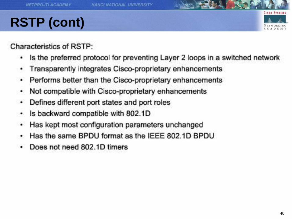
RSTP (cont)

41
RSTP BPDU
• RSTP (802.1w) uses type 2, version 2 BPDUs, so an RSTP
bridge can communicate 802.1D on any shared link or with
any switch running 802.1D
– Protocol information can be immediately aged on a port if
hellos are not received for three consecutive hello times,
6 seconds by default, or if the max age timer expires
– Because BPDUs are used as a keepalive mechanism,
three consecutively missed BPDUs indicate lost
connectivity between a bridge and its neighboring root or
designated bridge

42
RSTP BPDU (cont)

43
RSTP (cont) : Edge Port
• An RSTP edge port is a switch port that is never intended to
be connected to another switch device. It immediately
transitions to the forwarding state when enabled.
• Unlike PortFast, an RSTP edge port that receives a BPDU
loses its edge port status immediately and becomes a
normal spanning-tree port.

44
RSTP (cont) : Link Types
• The link type provides a categorization for each port
participating in RSTP
• The link type is automatically determined, but can be
overwritten with an explicit port configuration.
• Root ports do not use the link type parameter. Root ports are
able to make a rapid transition to the forwarding state as
soon as the port is in sync.
• Alternate and backup ports do not use the link type
parameter in most cases.
• Designated ports make the most use of the link type
parameter. Rapid transition to the forwarding state for the
designated port occurs only if the link type parameter
indicates a point-to-point link.

45
RSTP (cont) : Port States
• RSTP provides rapid convergence following a failure or
during re-establishment of a switch, switch port, or link.
• There are three possible RSTP port states: discarding,
learning, and forwarding.

46
RSTP (cont) : Port Roles

47
Configuring rapid PVST +

48
Configuring rapid PVST + (cont)

49
Design STP for Trouble Avoidance
• Know Where the Root Is
• Minimize the Number of Blocked Ports
50
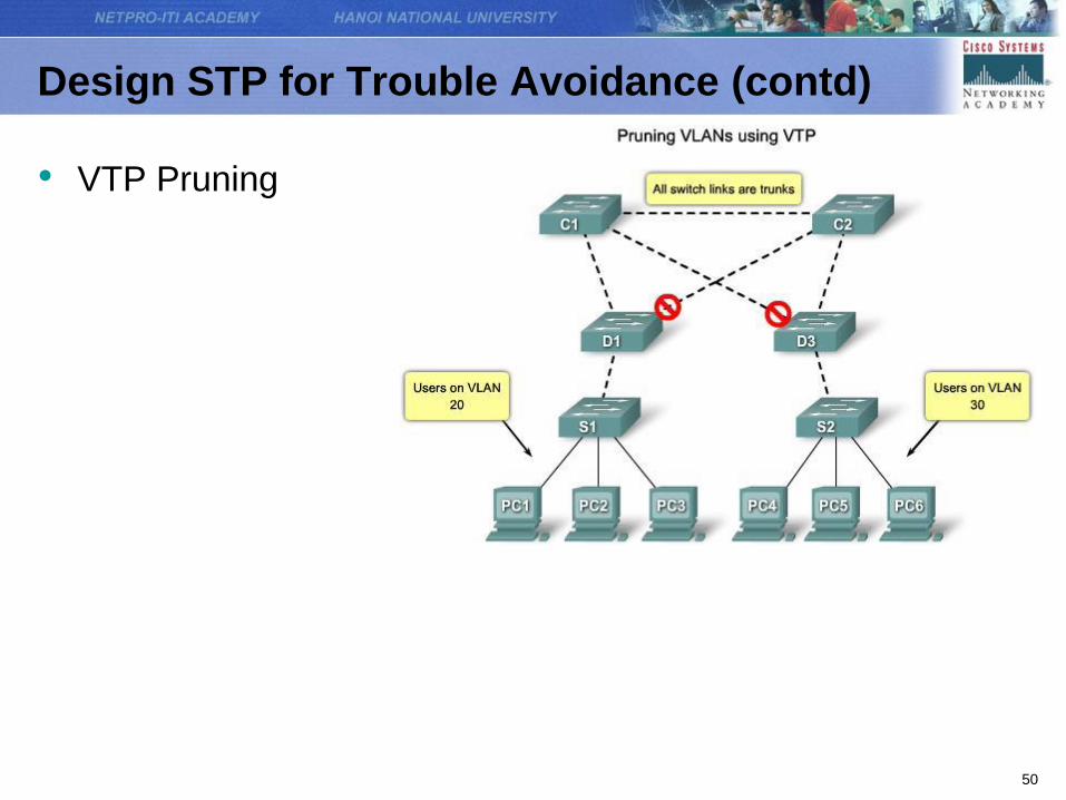
Design STP for Trouble Avoidance (contd)
• VTP Pruning

51
Design STP for Trouble Avoidance (contd)
• Use Layer 3 Switching
– There is no speed penalty with the routing hop and an
additional segment between C1 and C2.
– Core switch C1 and core switch C2 are Layer 3 switches.
VLAN 20 and VLAN 30 are no longer bridged between C1
and C2, so there is no possibility for a loop.
52
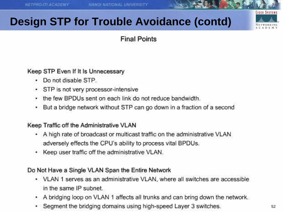
Design STP for Trouble Avoidance (contd)

53
Troubleshoot STP Operation

54
Troubleshoot STP Operation
• To troubleshoot a bridging loop, you need to know:
– The topology of the bridge network
– The location of the root bridge
– The location of the blocked ports and the redundant links
• Some possible failure
– Switch or Link Failure
– PortFast Configuration Error
– Network Diameter Issues

55
Switch or Link Failure

56
PortFast Configuration Error

57
Network Diameter Issues

58
Summary


