60
CAA Paper 2008/03 Helideck Design Considerations - Environmental Effects www.caa.co.uk Safety Regulation Group

CAA Paper 2008/03
Helideck Design Considerations - Environmental
Effects
www.caa.co.uk
Safety Regulation Group


CAA PAPER 2008/03
Helideck Design Considerations - Environmental
Effects
Safety Regulation Group
July 2009

CAA Paper 2008/03 Helideck Design Considerations - Environmental Effects
© Civil Aviation Authority 2009
All rights reserved. Copies of this publication may be reproduced for personal use, or for use within acompany or organisation, but may not otherwise be reproduced for publication.
To use or reference CAA publications for any other purpose, for example within training material forstudents, please contact the CAA at the address below for formal agreement.
ISBN 978 0 11792 257 0
Enquiries regarding the content of this publication should be addressed to:Research and Strategic Analysis, Safety Regulation Group, Civil Aviation Authority, Aviation House,Gatwick Airport South, West Sussex, RH6 0YR.
The latest version of this document is available in electronic format at www.caa.co.uk/publications,where you may also register for e-mail notification of amendments.
Published by TSO (The Stationery Office) on behalf of the UK Civil Aviation Authority.
Printed copy available from: TSO, PO Box 29, Norwich NR3 1GN www.tso.co.uk/bookshopTelephone orders/General enquiries: 0870 600 5522 E-mail: [email protected] orders: 0870 600 5533 Textphone: 0870 240 3701
CAA Paper 2008/03 Helideck Design Considerations - Environmental Effects
Part Page Date Part Page Date
Page iii
iii July 2009
Contents 1 July 2009
Foreword 1 July 2009
Executive Summary 1 July 2009
Report 1 July 2009
Report 2 July 2009
Report 3 July 2009
Report 4 July 2009
Report 5 July 2009
Report 6 July 2009
Report 7 July 2009
Report 8 July 2009
Report 9 July 2009
Report 10 July 2009
Report 11 July 2009
Report 12 July 2009
Report 13 July 2009
Report 14 July 2009
Report 15 July 2009
Report 16 July 2009
Report 17 July 2009
Report 18 July 2009
Report 19 July 2009
Report 20 July 2009
Report 21 July 2009
Report 22 July 2009
Report 23 July 2009
Report 24 July 2009
Report 25 July 2009
Report 26 July 2009
Report 27 July 2009
Report 28 July 2009
Report 29 July 2009
Report 30 July 2009
Report 31 July 2009
Report 32 July 2009
Report 33 July 2009
Report 34 July 2009
Report 35 July 2009
Report 36 July 2009
Report 37 July 2009
Report 38 July 2009
Report 39 July 2009
Report 40 July 2009
Report 41 July 2009
Report 42 July 2009
Report 43 July 2009
Report 44 July 2009
Report 45 July 2009
Report 46 July 2009
Report 47 July 2009
Report 48 July 2009
July 2009
List of Effective Pages

INTENTIONALLY LEFT BLANK

CAA Paper 2008/03 Helideck Design Considerations - Environmental Effects
Contents Page 1
List of Effective Pages iii
Foreword 1
Executive Summary 1
Report Helideck Design Considerations - Environmental Effects
Introduction and Background 1
Introduction 1Background 1
How To Use This Manual 3
Design Issues 4
Introduction 4Aerodynamic Issues and Criteria 4Plan Location of the Helideck 5Helideck Height and Air Gap under the Helideck 6Proximity to Tall Structures 7Temperature Rise due to Hot Exhausts 8Cold Flaring and Rapid Blow-down Systems 10Special Considerations for Floating Systems and Vessels 11Multiple Platform Configurations 16Combined Operations 17
Examples of Good and Bad Practice in Platform Helideck Location 18
Fixed Installations 18Semi-submersible and Jack-up Drilling Units 19Tension Leg Platforms 21FPSOs 22
Methods of Design Assessment 24
Wind Flow Assessment 24Wind Climate 28Prevailing Wind Direction 29Estimating Helideck Downtime due to Wind 32Presentation of Wind Flow Assessment Results 34Wave Motion Assessment 42Wave Climate 42Estimating Helideck Downtime due to Waves 46
Abbreviations 47
References 48
July 2009
Contents

INTENTIONALLY LEFT BLANK

CAA Paper 2008/03 Helideck Design Considerations - Environmental Effects
Foreword Page 1
Foreword
The production of the guidance material contained in this Paper was commissioned inresponse to a recommendation (ref. 10.3 (i)) that resulted from earlier research into offshorehelideck environmental issues, reported in CAA Paper 99004. The lack of any guidance ongood offshore helideck design practice was noted during that study, and the provision of suchmaterial identified as an important factor in addressing the underlying safety issues affectinghelicopter operations to offshore installations.
The material contained in this Paper was originally published in CAA Paper 2004/02. Thematerial has been updated to take account of progress in several research areas. In particular,a turbulence criterion has been introduced and the original vertical flow criterion removed (seeCAA Papers 2004/03 and 2008/02).
The work was jointly funded by the Safety Regulation Group of the UK Civil Aviation Authority(CAA) and the Offshore Safety Division of the Health & Safety Executive (HSE), and wasperformed by BMT Fluid Mechanics Limited. The content of CAA Paper 2004/02 has beenincorporated in the Offshore Helideck Design Guidelines document which the HSEcommissioned with the support of the CAA and the endorsement of the Offshore IndustryAdvisory Committee's Helicopter Liaison Group (OIAC HLG). The content of this paper is to beincorporated in an updated version of that document.
Safety Regulation Group
July 2009
July 2009

INTENTIONALLY LEFT BLANK

CAA Paper 2008/03 Helideck Design Considerations - Environmental Effects
Executive Summary Page 1
Executive Summary
This manual covering environmental effects on offshore helideck operations is a revision of adocument originally commissioned by the Health & Safety Executive (HSE) and the CivilAviation Authority (CAA). The original document was published as CAA Paper 2004/02 whichis referenced from the 5th Edition of CAP 437, Helicopter Landing Areas - Guidance onStandards. It was also incorporated in a comprehensive helideck design manual, producedunder the aegis of the Helicopter Liaison Group of the Health and Safety Commission'sOffshore Industry Advisory Committee (OIAC). This new version of the manual has beenproduced to reflect changes in the guidance since 2003.
It is almost inevitable that helidecks installed on the cramped topsides of offshore structureswill suffer to some degree from their proximity to tall and bulky structures, and to gas turbineexhausts and flares. The objective of this manual is to help platform designers to createoffshore installation topsides designs, and helideck locations, that are safe and 'friendly' tohelicopter operations and, as far as possible, avoid the 'environmental' effects (mainlyaerodynamic, thermal and wave motion) which can affect helicopter operations. It is hopedthat, if used from 'day one' of the offshore installation design process when facilities are firstbeing laid out, this manual will prevent or minimise many helideck environment problems atlittle or no cost to design or construction.
Guidance on the design and placement of offshore helidecks has existed for many years in thevarious editions of CAA document CAP 437, which have contained certain environmentalcriteria relating to the occurrence of vertical airflows and higher than ambient temperaturesdue to exhausts and flares. More recently a criterion for turbulence has been validated andadded, and the vertical flow criterion has been removed (see CAA Paper 2004/03 and CAAPaper 2008/02). These criteria were set in order to ensure safe helicopter operations byavoiding these hazards. Where these criteria could not be met, or where pilots experiencedother environmental phenomena, an entry has been placed in the Helideck Limitation List(HLL). These entries are specific to particular combinations of wind speed and direction, andeither restrict helicopter weight, or prevent flying altogether in the conditions.
The HLL system operated by the Helideck Certification Agency (HCA) should ensure thatlandings on offshore helidecks are properly controlled when adverse environmental effects arepresent. On poorly designed helidecks, severe restrictions may be placed on operationsresulting in reduced payloads or cancelled flights. This can lead to significant commercialpenalties for the installation operator or vessel owner. Well-designed and 'helicopter-friendly'platform topsides and helidecks therefore result in efficient operations, and a saving in cost forthe platform operator.
This manual, addressing helideck environmental effects, was produced with assistance from,and in consultation with, offshore installation operators/duty holders, helicopter operators,platform designers, marine contractors, drilling contractors, rig owners, trade associations andregulatory bodies.
The manual is split into three main sections. Design issues related to the location of thehelideck, and its juxtaposition with other facilities are considered in Section 3. In as manycases as possible, clear guidance is given on the preferred location of the helideck and itsrelationship with other potentially hazardous facilities or topside design features. The designissues are amplified by means of illustrative examples of good and bad design practice inSection 4. Methods for the qualitative and quantitative assessment of the design in terms ofhelicopter operability are described in Section 5.
July 2009

INTENTIONALLY LEFT BLANK

CAA Paper 2008/03 Helideck Design Considerations - Environmental Effects
Report Page 1
Report Helideck Design Considerations -
Environmental Effects
1 Introduction and Background
1.1 Introduction
This manual covering environmental effects on offshore helideck operations is arevision of a document originally commissioned by the Health & Safety Executive(HSE) and the Civil Aviation Authority (CAA) [1].The original document was publishedas CAA Paper 2004/02 which is referenced from the 5th Edition of CAP 437,Helicopter Landing Areas - Guidance on Standards. It was also incorporated in acomprehensive helideck design manual, produced under the aegis of the HelicopterLiaison Group of the Health and Safety Commission's Offshore Industry AdvisoryCommittee (OIAC). This new version of the manual has been produced to reflectchanges in the guidance since 2003.
The safety of offshore helicopter flight operations can be seriously affected byenvironmental effects that may be present around installations, vessels and theirhelidecks. These environmental effects are typified by structural turbulence, thethermal effects caused by gas turbine and diesel exhaust emissions, hot and cold gasstreams and vessel motions.
It is vital, in order to ensure the safety of helicopters operating to and from offshoreinstallations and vessels, that the best possible flying environment (minimumturbulence and helideck movement) is maintained.
Where, for operational and/or meteorological reasons, ideal flying conditions do notprevail, then flight crews need to have access to as much information as possible onthe anticipated turbulent conditions and helideck movements in order to plan (orabort) flight operations.
This section addresses, in detail, the environmental effects likely to be encountered,and provides information on how to identify problems during the design process andways that these adverse effects can be minimised and/or mitigated.
1.2 Background
It is almost inevitable that helidecks installed on the cramped topsides of offshorestructures will suffer to some degree from their proximity to tall and bulky structures,and to gas turbine exhausts and flares. The objective of this manual is to help platformdesigners to create offshore installation topsides designs, and helideck locations, thatare safe and 'friendly' to helicopter operations and, as far as possible, avoid the'environmental' effects (mainly aerodynamic, thermal and wave motion) which canaffect helicopter operations. It is hoped that, if used from 'day one' of the offshoreinstallation design process when facilities are first being laid out, this manual willprevent or minimise many helideck environment problems at little or no cost to designor construction.
Guidance on the design and placement of offshore helidecks has existed for manyyears in the various editions of CAA document CAP 437 [2], which have containedcertain environmental criteria relating to the occurrence of vertical airflow, turbulence,and higher than ambient temperatures due to exhausts and flares. More recently acriterion for turbulence has been added and the vertical flow criterion has beenremoved (see [3] and [4]). These criteria were set in order to ensure safe helicopter
July 2009

CAA Paper 2008/03 Helideck Design Considerations - Environmental Effects
Report Page 2
operations by avoiding these hazards. Where these criteria could not be met, orwhere pilots experienced other environmental phenomena, an entry has been placedin the Helideck Limitation List (HLL) [5]. These entries are specific to particularcombinations of wind speed and direction, and either restrict helicopter weight, orprevent flying altogether in certain weather conditions.
The HLL system operated by the Helideck Certification Agency (HCA) should ensurethat landings on offshore helidecks are properly controlled when adverseenvironmental effects are present. On poorly designed helidecks, severe restrictionsmay be placed on operations resulting in reduced payloads or cancelled flights. Thiscan lead to significant commercial penalties for the installation operator or vesselowner. Well-designed and 'helicopter-friendly' platform topsides and helideckstherefore result in more efficient operations, and a saving in cost for the platformoperator.
A survey based on pilot responses to a questionnaire on workload and safety hazards[6] rated 'turbulence around platforms' as the largest source of workload andpresenting the largest safety risk of all aspects of offshore flight operations. A reviewof offshore helideck environmental issues [8] pointed out that many of the decisionsleading to poor helideck performance were made by designers in the very earlystages of design, and recommended that it would be easier for designers to get thesedecisions right if comprehensive helideck design guidance published by industry wasavailable to run in parallel with CAP 437.
This manual, addressing helideck environmental effects, has been produced withassistance from, and in consultation with, offshore installation operators/duty holders,helicopter operators, platform designers, marine contractors, drilling contractors, rigowners, trade associations and regulatory bodies.
July 2009
CAA Paper 2008/03 Helideck Design Considerations - Environmental Effects
Report Page 3
2 How To Use This Manual
This manual is intended for use throughout the design life of an offshore installationor vessel. It should be used at the very earliest stages of concept design when themain deck elements are being laid out. It should be used during detailed design, andat any stage in later life when changes to the superstructure are being contemplated.
The main part of the manual, Section 3, is organised in terms of the main designdecisions that need to be made when determining the general arrangement ofinstallations and vessels, and in selecting the optimum location for the helideck. Itrecommends various design features, and clearances from topsides elements thatmay be sources of turbulence or hot gases. Section 3 also describes how the wavemotions of floating installations and vessels can influence helideck availability, andhow this can vary significantly depending on the helideck location on the vessel.Examples of good and bad layouts are presented in Section 4. Section 5 describeshow assessments of helideck performance can be made at the various stages in thedesign process.
It is recognised that it will often not be possible to comply with all the aspects of goodpractice recommended in this design manual. However, the assessment methodsoutlined in Section 5 make it possible to estimate the likely helideck operabilitypenalty associated with deviations from the ideal, and this knowledge can then beused as a basis for rational decision-making on the best design compromise.Information from helideck flow assessment studies should also be made available tothe HCA prior to flight operations in order that any necessary operational limitationscan be imposed prior to service to ensure that safety is not compromised.
The material in this manual is intended to help the platform designer with basic layoutin the design process. The manual is not a substitute for formal assessment, andcompliance with the guidelines cannot guarantee compliance with the varioushelideck performance criteria. Such compliance can only be assessed on a case-by-case basis by suitably qualified experts using methods such as those described inSection 5.
July 2009

CAA Paper 2008/03 Helideck Design Considerations - Environmental Effects
Report Page 4
3 Design Issues
3.1 Introduction
The design guidance in this document applies to all fixed installations (manned andnormally unattended installations), floating installations including semi-submersibles(e.g. MODU's, FPU's and specialist barges) and vessel hull based FPSO's, and anyother specialist offshore support vessels with a helideck (e.g. seismic, diving support,pipelay).
The environmental effects described in this section fall into two classes;
• aerodynamic effects, and
• wave motion effects.
All offshore installations experience the aerodynamic effects described in Sections3.2 - 3.7, but it is only floating systems that experience the influences of wavemotions on the helideck as described in Section 3.8.
Turbulent airflows and thermal effects are in effect 'invisible' obstructions in flightpaths around installations and vessels. They can seriously affect flight operations ontoa helideck. These effects must be identified, quantified and taken fully into accountwhen establishing the operability of a helideck.
The environmental issues described in this manual are clearly not the only factors inthe selection of the helideck design or location. It is also strongly influenced by otherimportant practical, safety and regulatory factors. For example, on many installationsthe helicopter will be designated the 'primary means of escape', and so the helideckmust be close to the 'temporary refuge'. Selection of the best helideck location istherefore invariably a compromise between a number of potentially conflictingrequirements.
3.2 Aerodynamic Issues and Criteria
Helidecks are basically flat plates and so are relatively streamlined structures. Inisolation they would present little disturbance to the wind flow, and helicopters wouldbe able to operate to and from them in a more or less undisturbed airflowenvironment. Difficulties arise because the wind must deviate around the bulk of theoffshore installation causing large areas of flow distortion and turbulent wakes, andbecause the installation is also often a source of hot or cold gas emissions.
The effects fall into three main categories (see Figure 1):
• The flow around the bulk of the offshore installation itself. Platforms are slab-sided,non-streamlined assemblies ('bluff bodies') which create regions of highlydistorted and disturbed airflow in their vicinity.
• The flow around large items of superstructure, notably cranes, drilling derricks andexhaust stacks. Like the platform itself, these are bluff bodies, and it is theturbulent wake flows behind these bodies that are important.
• Hot gas flows emanating from exhaust outlets and flare systems.
The current design criteria are based ultimately on achieving two objectives:
• The turbulence, defined as the standard deviation of the vertical airflow velocity,shall not exceed 1.75m/s1.
• The maximum temperature rise, averaged over a 3 second time interval, in thevicinity of the flight path and over the landing area, shall not exceed 2°C.2
1. The 2.4m/s value given in CAP 437 5th Edition was lowered following completion of the validation exercise.2. The issue arises of how high above the landing area these criteria should be applied. CAP 437 [2] states that this should
be "…up to a height above the helideck corresponding to 30 ft plus wheels-to-rotor height plus one rotor diameter".
July 2009

CAA Paper 2008/03 Helideck Design Considerations - Environmental Effects
Report Page 5
These criteria are defined in CAP 437 [2] and are taken to be the limiting conditionsfor safe helicopter operation. If they are exceeded under any conditions then thehelicopter operator is to be advised, and in most circumstances an appropriate flightlimitation should be entered into the HLL [5].
3.3 Plan Location of the Helideck
A key driver of the helideck location in [2] is the need to provide a generous sectorclear of physical obstructions for the approaching/departing helicopter, and alsosufficient vertical clearance for the helicopter to lose altitude after take-off in theevent of a single engine failure. This requirement is for a minimum 210° obstacle freesector, with a falling 5:1 gradient below the landing area over at least 180° of this arc.
Figure 1 Sketch showing the main elements of aerodynamic flow interaction
Figure 2 Sketch showing the helideck installed over a corner with 50% overhang
July 2009

CAA Paper 2008/03 Helideck Design Considerations - Environmental Effects
Report Page 6
From an aerodynamic point of view the helideck should be as far away as possiblefrom the disturbed wind flow around the platform. This objective, and the 210°obstacle-free sector, are most readily achieved by locating the helideck on a corner ofthe platform with as large an overhang as possible. In combination with an appropriateelevation and air gap (see Section 3.4), the overhang will encourage disturbed airflowto pass under the deck leaving a relatively horizontal and clean flow over the top.
It is recommended that the overhang should be such that the centre of the helideckis vertically above, or outboard of, the corner of the installation superstructure (seeFigure 2).
3.4 Helideck Height and Air Gap under the Helideck
The height of the helideck, and the presence of an air gap between the helideck andthe supporting module are the most important factors in determining wind flowcharacteristics. The helideck should ideally be located at a height above, or at leastequal to, all significant surrounding structures. This will minimise the occurrence ofturbulence downwind of adjacent structures.3
An air gap, separating the helideck from superstructure beneath it, promotesbeneficial wind flow over the helideck. If there is not an air gap under the helideck,then wind conditions immediately above the helideck are likely to be severe,particularly if the helideck is mounted on top of a large multi-story accommodationblock. It is the distortion of the wind flow around the bulk of the platform that is thecause.
Based on previous research work [8] it is recommended that the air gap on productionplatforms should be in the range 3m - 5m. Helidecks mounted on very tallaccommodation blocks require the largest clearance, while those on smaller blocksand with very large helideck overhangs tend to require less. For shallowsuperstructures of three stories or less, such as often found on semi-submersibledrilling vessels, a 1m gap may be sufficient.
In combination with an appropriate overhang (see Section 3.3), the air gap encouragesthe disturbed airflow to pass under the deck leaving a relatively linear and clean flowover the top (see Figure 3).
3. However, note that CAP 437 recommends that the helideck height should not exceed 60m above sea level. Above thisheight the regularity of helicopter operations may be affected by low cloud base conditions.
Figure 3 Sketch showing the flow passing under the helideck and clean flow over
July 2009

CAA Paper 2008/03 Helideck Design Considerations - Environmental Effects
Report Page 7
It is essential that the air gap is preserved throughout installation operational life, anddoes not become a storage area for bulky items that might obstruct the free flow ofair through the gap.
3.5 Proximity to Tall Structures
Offshore installation topsides tend to include a number of tall structures (drillingderricks, flare towers, cranes, gas turbine exhaust stacks etc.), and it is usuallyimpractical to mount the helideck at a higher elevation. All such tall structures willcause areas of turbulent or sheared flow downwind that may potentially pose a hazardto the helicopter. The severity of the disturbances is greater the bluffer the shape, andthe broader the obstruction to the flow. It is reduced the greater the distancedownwind.
It should be noted that the location and configuration of drilling derricks can varyduring the field life. The derrick position over the well slots can change, and temporarywork-over rigs may be installed from time to time. The assessment of the helidecklocation should take into account the various derrick configurations that are expectedto occur during the life of the installation.
3.5.1 Clad Derricks
A fully clad drilling derrick is a tall and solid structure and generates a correspondinglysignificant wake. The important flow property of the wake is that it is unsteady andso, if it is upwind of the helideck, it subjects the helideck area to large and randomvariations in wind speed and direction.
A general guide on wake decay from bluff bodies indicates that wake effects largelydissipate within a downwind distance of 10-20 structure widths. For a clad derrick 10m wide at helideck level, this would correspond to a decay distance of 100-200 m (seeFigure 4).
Consequently it is best if the helideck is not placed closer than 10 structure widthsfrom a tall solid structure such as a clad derrick. However, few offshore installationswill be large enough to permit such a clearance to be included in the design, and sothe specification of a clad derrick is almost certain to result in a significant operationallimitation for helicopters when the derrick is upwind of the helideck. It will beparticularly important to try to ensure that the installation is aligned such that this onlyhappens in rarely occurring wind directions (see Section 5.3).
Figure 4 Sketch showing plan view of flow behind a clad and an unclad derrick
July 2009

CAA Paper 2008/03 Helideck Design Considerations - Environmental Effects
Report Page 8
3.5.2 Unclad Derricks and Cranes
Unclad derricks are relatively porous. A wake still exists, but the turbulence is of amuch higher frequency and smaller scale due to the flow being broken by the latticeelements of the structure. A helideck can therefore be safely located closer to anunclad derrick than its clad equivalent. Ideally the separation between the helideckand an unclad open lattice derrick should be at least five times the derrick width athelideck height (see Figure 4). Separations of significantly less than 5 derrick widthsmay lead to the imposition of operating restrictions in certain wind conditions.
Crane pedestals and crane booms are also usually of lattice construction, and thesame approximate rule can be applied as for lattice derricks. Generally the disturbedflow region will be much less due to their smaller dimensions.
3.5.3 Exhaust stacks
Gas turbine and other exhaust stacks, whether operating or not, also represent aphysical blockage to the flow and create a turbulent wake (as well as the potentialhazard due to the hot exhaust - see Section 3.6).
The same guideline as defined for clad derricks is recommended, namely, a minimumof 10 structure widths between the stacks and the helideck. If there are multipleexhausts and these are located in close proximity to each other, then it isrecommended that the structure width be considered to be the overall span of thegroup of stacks.
3.5.4 Other Enclosed Structures
Some offshore drilling rigs include large enclosed structures in close proximity to thedrilling derrick (e.g. shaker houses). If the height of these structures extends tohelideck elevation, then they may give rise to large-scale turbulent disturbancesdownwind, and should be treated similarly to a clad derrick.
3.5.5 Lay-down Areas
A lay-down area in the vicinity of a helideck poses a number of potential problems tohelicopter operations. Bulky or tall items placed in a lay-down area close to a helideckmay result in turbulence. The temporary nature of such lay-down areas increases thepotential hazard because the helicopter pilots, though perhaps familiar with theinstallation, may not be expecting turbulence.
The platform design should seek to ensure that lay-down areas are significantly belowhelideck level or sufficiently remote from the helideck to avoid such problems. If thiscannot be achieved then it is essential that management procedures are in place toensure that appropriate limitations are placed on flight operations, or that tall or bulkyitems are removed from temporary lay-down areas during helicopter operations.
3.6 Temperature Rise due to Hot Exhausts
Increases in ambient air temperature are a potential hazard to helicopters. Increasedair temperature means less rotor lift and less engine power margin. Rapidtemperature changes can also induce engine surge and even compressor stall orflameout.
It is therefore extremely important that helicopters avoid these conditions, or that theoccurrence of higher than ambient conditions is foreseen, and steps taken to reducepayload to provide an appropriate performance margin.
Gas turbine power generation systems are usually the most significant source of hotexhaust gases on offshore production platforms, but diesel propulsion or auxiliarypower system exhausts on mobile units may also need to be considered.
July 2009

CAA Paper 2008/03 Helideck Design Considerations - Environmental Effects
Report Page 9
For certain wind directions the hot gas plumes from the exhausts will be carried bythe wind directly across the helideck. The hot gas plume mixes with the ambient air,and the mixing increases the size of the plume, and reduces the temperature (bydilution).
Evaluations of likely temperature rise, based on a Gaussian dispersion model andsupported by wind tunnel tests, indicate that for gas turbine exhausts with releasetemperatures up to 500°C and flow rates of 50-100 kg/s, the minimum distancerequired before the temperature rise drops to 2°C rise above ambient is in range 130-190 m (see Figure 5). Some gas turbine power generation systems include wasteheat recovery systems that have lower exhaust gas temperatures of about 250°C,resulting in reduced minimum distances in the range 90-130m.
Except for very large platforms, this implies that regardless of design, there willalways be a wind condition where temperature rise above the helideck exceeds 2°C.It is likely to be impossible, therefore, to design a helideck that is compliant with thecriteria under all conditions. The design aim becomes one of minimising theoccurrence of high temperatures over the helideck rather than eliminating them. Thiscan be achieved by trying to ensure that platform layout and alignment direction aresuch that these conditions are only experienced rarely (see Section 5.3).
Many offshore installations have the power generation modules and exhausts locatedclose to the accommodation modules and helideck. This is because the powergeneration is regarded as significantly less hazardous than drilling or productionmodule activities. This can be a good location provided that the stacks are highenough to keep the exhaust gas plume clear of arriving/departing helicopters, are notwide enough to cause large amounts of turbulence, and do not impinge on the'obstacle protected surfaces'.
The helideck should be located such that winds from the prevailing wind directionscarry the plume away from the helicopter approach/departure paths. To minimise theeffects for other wind directions, the exhausts should be sufficiently high to ensurethat the plumes are above the helicopter approach/departure paths. To achieve this,
Figure 5 Sketch showing the hot gas plume dispersing, and 2°C rise 130-190m downwind
July 2009

CAA Paper 2008/03 Helideck Design Considerations - Environmental Effects
Report Page 10
it is recommended that the exhaust outlets are no less than 20-30 m above thehelideck, depending on the gas turbine flow rates and temperatures.4
In the past, some platforms were fitted with downward facing exhausts so that thehot exhaust gases were initially directed down towards the sea surface. Thisarrangement is not recommended because the hot plume can rise and disperse in anunpredictable way, particularly in light wind conditions.
In situations where it is difficult or impractical to reduce the potential interactionbetween the helicopter and the turbine exhaust plumes to a sufficiently low level,consideration should be given to installing an exhaust plume visualisation system [7].This will highlight the hazard to pilots and thereby minimise its effects by making iteasier to avoid encountering the plume.
3.7 Cold Flaring and Rapid Blow-down Systems
Hydrocarbon gas can be released from the production platform process or fromdrilling rigs at various times. It is important to ensure that a helicopter cannot fly intoa cloud of hydrocarbon gas because [8];
• concentrations above 10% of Lower Flammable Limit (LFL) might cause thehelicopter engine to surge or flameout with consequent risk to the helicopter, and
• the helicopter poses a risk to the offshore installation because it is a potentialignition source for the hydrocarbon gas.
Consideration therefore needs to be given to ensuring that gas release points are asremote as possible from the helideck and helicopter flight path, and that anyunforeseen gas releases activate the helideck status lights (flashing red). Planned gasreleases should only occur when helicopters are not in the area.
The blow-down system on a production platform depressurises the process systemreleasing the hydrocarbon gas. It will normally be designed to reduce the pressure tohalf, or to 7 bar, in 15 minutes (the API standard). For a large offshore installation thismight require the release of 50 tonnes of gas or more. Once down to this targetpressure in 15 minutes or less, the remainder of the gas will continue to be releasedfrom the system. A blow-down may be automatically triggered by the detection of adangerous condition in the production process. Alternatively it may be triggeredmanually.
The blow-down system should have venting points that are as remote as possiblefrom the helideck and, in prevailing winds, downwind of the helideck. It is commonto have this vent on the flare boom, and this will normally be a good location.However, it should be noted that dilution of the gas to 10% LFL may not occur untilthe plume is a considerable distance from the venting point. This distance could beanywhere between 200m - 500m depending on vent size, venting rate and windspeed.
4. Where it is considered necessary to extend the gas turbine exhaust outlets, it is important for the design project team toconsider early on in the project how the installation of extended outlets can reasonably be achieved. Ideally, theengineering requirement should be established before firming up the gas turbine prime mover specification(s). It isimportant to consider the potential effects on operating performance and extra maintenance requirements caused byextending the gas turbine prime mover exhaust ducts, particularly when they are used in conjunction with some wasteheat recovery systems (it may result in an increase in back pressure on the turbine). A complete picture of the exhaust /flare plume and its potential extremities (i.e. under normal operating and maximum output conditions) for a full range ofwind conditions is required. Test Houses will require project teams and manufacturers to furnish them with full detailsfor the varying load conditions, mass flows and exhaust temperatures for all possible operating conditions.
July 2009

CAA Paper 2008/03 Helideck Design Considerations - Environmental Effects
Report Page 11
Drilling rigs often have 'poor-boy degassers' which are used to release gas whilecirculating a well, but a drilling rig is unlikely to release any significant quantities of gaswithout warning, unless there is a sudden major crisis such as a blow-out. As withproduction platforms it is unlikely to be possible to locate the helideck sufficientlydistant from the potential gas sources to guarantee 10% LFL or less, and so the rigshould not accept helicopter flights when well circulation activity is going on, or whenthere are problems down the well. Helideck status lights should be connected to theappropriate gas detection systems and automatically initiated.
3.8 Special Considerations for Floating Systems and Vessels
3.8.1 General
As well as experiencing the aerodynamic effects and potential hazards outlinedabove, floating installations and vessels experience dynamic motions due to theocean waves. These motions (see Figure 6) are a potential hazard to the helicopter,and operational motion limits are set in order to avoid unsafe conditions.
The setting of these operating limits should involve consideration of two aspects:
• motion limits for executing a safe landing, and
• limits for safely remaining on the deck for the period necessary to effect passengerand cargo transfer (usually not more than 20 minutes).
The former is mainly affected by the rate of the heave (vertical) motion, but also bythe roll and pitch motions, and is relatively easy for the pilot to judge visually. The pilotcan see the movements of the vessel, and can judge whether it is safe to make thelanding, and can choose the appropriate moment to set the helicopter down.
The latter is mainly affected by helideck accelerations, which can be generateddirectly by the motion of the vessel (heave, surge and sway) and indirectly due to theinclination of the helideck (component of gravity due to pitch or roll angle), andaerodynamic loads such as rotor lift and airframe drag. Limits for remaining safely onthe deck are also much more difficult to judge because they should involve aprediction of the helideck motions for the period that the helicopter will be on thedeck which should include an assessment of the statistical risk of unsafe motions.Furthermore, the options available to the pilot in the event of excessive motionsbuilding up while the aircraft is on the helideck are limited.
Figure 6 Vessel wave motions definition
July 2009
CAA Paper 2008/03 Helideck Design Considerations - Environmental Effects
Report Page 12
3.8.2 Wave Motion Characteristics and Criteria
The setting of helideck performance limitations due to vessel motion is theresponsibility of the helicopter operator as the AOC holder. Currently in the UKoffshore helicopter-operating environment the motion limitations for a variety ofvessels have been agreed and set jointly by the helicopter operators, and these arepublished by HCA in the HLL [5]. It is recommended that vessel owners anddesigners consult with the Helideck Certification Agency during conceptional designof new vessels or refits to determine the limitations that are likely to be applied to theclass of vessel for given helicopter types.
The limitations that currently exist apply to both the vertical linear motion (heave/heave rate) and the angular motions (roll and pitch). Large accelerations can cause thehelicopter to slide across the deck or tip over (though these do not currently form partof the limitations applied5).
The angle of roll and pitch experienced is the same for all points on the vessel orstructure, but the amount of heave, sway or surge motion experienced can varyconsiderably depending on the location of the helideck on the vessel.
The severity of the helideck motions will depend on:
• The wave environment (e.g. more severe West of Shetland than in the SouthernNorth Sea).
• The size of the vessel (a small vessel generally tends to exhibit larger and fasterwave induced motions than a large vessel).
• The vessel's motion characteristics (certain hull forms exhibit larger wave inducedmotions than others, or are sensitive to particular sea conditions).
• Whether the vessel is moored, underway or under tow.
• The location of the helideck (vertical motions tend to be greater at the bow andstern of a ship than at midships, and sway motions due to roll tend to increase withhelideck height).
Helicopter operational limitations will depend on:
• The design of the helicopter itself (different motion limits apply to differenthelicopter types [5]).
• Day time / night time (more onerous motion limits are applied to helidecks in thehours of darkness due to the degraded visual cues available to the pilot [5, 9]).
• The size of the vessel (the motion characteristics of large vessels are generallymore benign than for small vessels).
• The visual cueing environment (the pilot will often have relatively few visual cuesto judge landings on bow-mounted helidecks when landing facing forwards, andon helidecks mounted above the bridge superstructure when landing facingabeam).
NOTE: The helicopter operating limits associated with the new acceleration-based criterion will also be a function of the 10 minute mean wind speed.
5. Work on a new acceleration-based helideck motion criterion, which also takes account of the exacerbating effect of thewind on the risk of the helicopter sliding or tipping, is nearing completion - see Section 5.7.1 and [15].
July 2009

CAA Paper 2008/03 Helideck Design Considerations - Environmental Effects
Report Page 13
3.8.3 Sea State Characterisation
Sea states are usually characterised in terms of the significant wave height, anassociated wave period (usually either the mean zero up-crossing period or peakspectral period) and a wave energy spectrum. Standard wave spectral formulae, suchas the JONSWAP or Pierson-Moskowitz spectrum, are commonly used in design todefine the way in which wave energy is distributed across the wave frequency range.Wave spectra may be defined as either uni-directional or multi-directional, the latterdescribing the proportion of wave energy coming from each direction by means of adirectional spreading function.
3.8.4 Vessel Motions and Helideck Downtime
The motions of a vessel or floating installation generally become larger as thesignificant wave height and period increase, but may be especially severe at certainwave periods (e.g. at natural roll or pitch periods), and may be sensitive to thefrequency content of the wave spectrum. The motion characteristics of a vessel orfloating platform may be reliably predicted by recourse to well-established computermodels, or to physical model testing.
Helideck downtime will occur whenever the motions of the vessel exceed the criteria[5]. (See Section 5.8 for an outline of a method to estimate the downtime.)
3.8.5 Helideck Location Dependence
The heave motions of the helideck depend on its horizontal location, and on how thevessel's heave, roll and pitch motions combine at that location. The operability of thehelideck therefore depends on its location on the vessel or floating installation, bothlongitudinally and transversely.
This location dependence is particularly marked for ships and ship-shapedinstallations such as FPSOs. The pitching motion of a ship is such that the verticalheave motion experienced at the helideck will generally be much greater if it islocated at the bow or stern, and will be least if it can be located amidships. Bow-mounted helidecks can also be particularly vulnerable to damage from green seasunless mounted high above deck level.
Figure 7 Areas of larger wave motions on a ship-shaped vessel
July 2009
CAA Paper 2008/03 Helideck Design Considerations - Environmental Effects
Report Page 14
Helidecks are also often located off the vessel's centreline. In some cases they arecantilevered over the side (which provides the benefit of an unobstructed falling 5:1gradient over at least 180°). In this case, downtime due to wave motions will generallytend to increase because of greater helideck heave motions caused by roll.
Semi-submersible drilling or production platforms, tension leg platforms and sparbuoys tend to have smaller motions at lower frequencies and, while the helidecklocation on a spar or semi-submersible will have an effect on performance, this ismuch less important than for a ship-shaped vessel.
However, the location of the helideck is generally determined by factors other thanthe need to minimise heave motions. In the case of an FPSO or drillship, for example,the central deck area is generally occupied by processing or drilling equipment. Thehelideck also has to be conveniently located for access by personnel who aregenerally accommodated either near the bow or stern. As the helicopter is likely to bethe 'primary means of escape' the helideck needs to be close to the 'temporaryrefuge', which is usually incorporated into the accommodation.
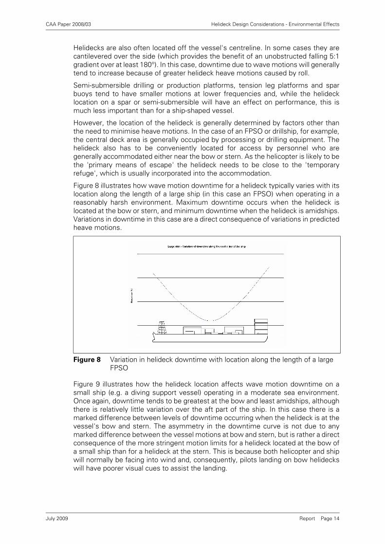
Figure 8 illustrates how wave motion downtime for a helideck typically varies with itslocation along the length of a large ship (in this case an FPSO) when operating in areasonably harsh environment. Maximum downtime occurs when the helideck islocated at the bow or stern, and minimum downtime when the helideck is amidships.Variations in downtime in this case are a direct consequence of variations in predictedheave motions.
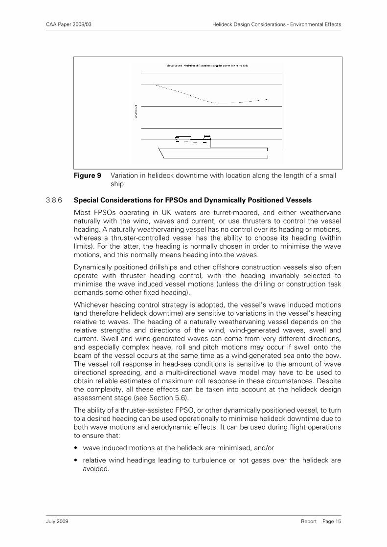
Figure 9 illustrates how the helideck location affects wave motion downtime on asmall ship (e.g. a diving support vessel) operating in a moderate sea environment.Once again, downtime tends to be greatest at the bow and least amidships, althoughthere is relatively little variation over the aft part of the ship. In this case there is amarked difference between levels of downtime occurring when the helideck is at thevessel's bow and stern. The asymmetry in the downtime curve is not due to anymarked difference between the vessel motions at bow and stern, but is rather a directconsequence of the more stringent motion limits for a helideck located at the bow ofa small ship than for a helideck at the stern. This is because both helicopter and shipwill normally be facing into wind and, consequently, pilots landing on bow helideckswill have poorer visual cues to assist the landing.
Figure 8 Variation in helideck downtime with location along the length of a large FPSO
July 2009
CAA Paper 2008/03 Helideck Design Considerations - Environmental Effects
Report Page 15
3.8.6 Special Considerations for FPSOs and Dynamically Positioned Vessels
Most FPSOs operating in UK waters are turret-moored, and either weathervanenaturally with the wind, waves and current, or use thrusters to control the vesselheading. A naturally weathervaning vessel has no control over its heading or motions,whereas a thruster-controlled vessel has the ability to choose its heading (withinlimits). For the latter, the heading is normally chosen in order to minimise the wavemotions, and this normally means heading into the waves.
Dynamically positioned drillships and other offshore construction vessels also oftenoperate with thruster heading control, with the heading invariably selected tominimise the wave induced vessel motions (unless the drilling or construction taskdemands some other fixed heading).
Whichever heading control strategy is adopted, the vessel's wave induced motions(and therefore helideck downtime) are sensitive to variations in the vessel's headingrelative to waves. The heading of a naturally weathervaning vessel depends on therelative strengths and directions of the wind, wind-generated waves, swell andcurrent. Swell and wind-generated waves can come from very different directions,and especially complex heave, roll and pitch motions may occur if swell onto thebeam of the vessel occurs at the same time as a wind-generated sea onto the bow.The vessel roll response in head-sea conditions is sensitive to the amount of wavedirectional spreading, and a multi-directional wave model may have to be used toobtain reliable estimates of maximum roll response in these circumstances. Despitethe complexity, all these effects can be taken into account at the helideck designassessment stage (see Section 5.6).
The ability of a thruster-assisted FPSO, or other dynamically positioned vessel, to turnto a desired heading can be used operationally to minimise helideck downtime due toboth wave motions and aerodynamic effects. It can be used during flight operationsto ensure that:
• wave induced motions at the helideck are minimised, and/or
• relative wind headings leading to turbulence or hot gases over the helideck areavoided.
Figure 9 Variation in helideck downtime with location along the length of a small ship
July 2009

CAA Paper 2008/03 Helideck Design Considerations - Environmental Effects
Report Page 16
Consequently, a thruster-assisted FPSO or dynamically positioned vessel withrelatively poor inherent wave induced motions and helideck aerodynamic limitationsmay nevertheless be operated in such a way that good helideck operability isachieved. The benefit of this can also be taken into account at the helideck designassessment stage (see Section 5). However, it should also be recognised that asudden loss of heading control during helicopter operations is likely to result in a rapidincrease in vessel motions (especially roll) and an adverse relative wind direction withpotentially catastrophic consequences for a helicopter on the deck. This roll motionproblem will be particularly severe for vessels with high-mounted helidecks.Consequently, heading control should not be relied upon unless the heading controlsystem has adequate integrity and capacity to bring the vessel back onto heading, andthe risk of loss of heading control has been shown to be appropriately low.
3.9 Multiple Platform Configurations
It is common for offshore installations to consist of more than one platform or vessel.In some cases fixed platforms are bridge-linked and in quite close proximity (e.g.Figure 10), and are close enough for the aerodynamic effects (turbulence, hot gasesetc.) of one platform to be experienced at the helideck of the other when the wind isin the appropriate direction.
In these situations the various effects considered in Sections 3.2 - 3.7 must beconsidered for the platform complex as a whole. It will normally be necessary for thehelideck to be located on the platform corners remote from the other platform(s) inorder to comply with the 210° obstacle-free sector, and for best aerodynamicperformance.
Figure 10 Computer generated visualisation of a hot gas plume from downward facing exhausts enveloping the helideck on an adjacent bridge-linked platform
July 2009
CAA Paper 2008/03 Helideck Design Considerations - Environmental Effects
Report Page 17
In some cases the platform complex may include more then one helideck, and it willtherefore be necessary to assess the design issues for each of these helidecks.However, operational limitations which have to be placed on an individual deck maycause little helicopter downtime if there is an alternate helideck that can be usedunder these conditions. All such limitations need to be fully investigated,documented, and communicated to the operators to ensure that the variousmanagement procedures to control the use of the helidecks are put into place.
3.10 Combined Operations
Combined operations refer to a temporary arrangement where at least one mobileplatform or vessel (e.g. a flotel) is operating in close proximity to another permanentinstallation. In many cases there may be a gangway in place connecting the two.
While the detailed arrangements for these combined operations may varyconsiderably from one circumstance to another, there are certain aspects of designand platform topsides layout that, if optimised, can minimise the need for helideckrestrictions during combined operations.
Certain types of mobile platforms (e.g. flotels) have gangways and/or gangwaylanding portals, and clearly this defines the side of the mobile platform that willnormally be closest to the fixed platform when combined operations are in progress.Consequently the design of the flotel should have the gangway located as far awayfrom the helideck as practicable in order to maximise the available obstacle-freesector, and also to ensure that turbulence or hot gas plumes caused by the adjacentfixed platform are as distant from the mobile platform helideck as possible.
Whatever considerations and choices were made at the fixed or mobile platformdesign stage, when combined operations are to be carried out, a helideck assessmentshould be conducted to evaluate the effect of one platform on the other, anddetermine any helideck restrictions that should be imposed. Apart from the physicalrequirements for an unobstructed 210° obstacle free sector and falling 5:1 gradient(over at-least 180°), this assessment should consider the effect of the turbulent wakefrom one platform impinging on the helideck of the other, and any hot gas exhaustsfrom one platform influencing the approach to the other helideck. The helideck on amobile unit is likely to be at a much lower level than the bulk of the fixed platform itis alongside, and is therefore likely to experience severe turbulence when downwind.
These considerations are likely to determine that, under certain wind conditions,helideck operations to the mobile unit need to be curtailed. Where the combinedoperations have more than one helideck available and a gangway platform forpersonnel, it may be possible to switch from using one helideck to the otherdepending on the conditions. All such limitations need to be fully investigated,documented, and communicated to the helicopter operators to ensure that thevarious management procedures to control the use of the helidecks are put into place.
July 2009

CAA Paper 2008/03 Helideck Design Considerations - Environmental Effects
Report Page 18
4 Examples of Good and Bad Practice in Platform Helideck Location
This section contains sketches of the main types of offshore installation (fixed jacket,semi-submersible, jack-up, tension leg platform and FPSO) with examples of each,illustrating good and poor practice in helideck location.
4.1 Fixed Installations
• Good: Helideck is above the level of the surrounding main modules.
• Bad: Two large clad derricks present a major solid obstruction to the wind flow andthe helideck will experience serious turbulence when downwind. A set of four gasturbine exhaust stacks is also located close to the helideck. They are not highenough to prevent problems with hot gas exhausts, and are also a significantobstruction to the wind flow over the helideck at certain wind headings. Thehelideck has insufficient overhang and air gap.
• Good: The helideck is mounted significantly above the level of all the platformmodules, and with an appropriate air gap beneath. The only structure abovehelideck level is the derrick, which is unclad, and therefore likely to produce littlesignificant turbulence at the helideck.
Figure 11
Figure 12
July 2009
CAA Paper 2008/03 Helideck Design Considerations - Environmental Effects
Report Page 19
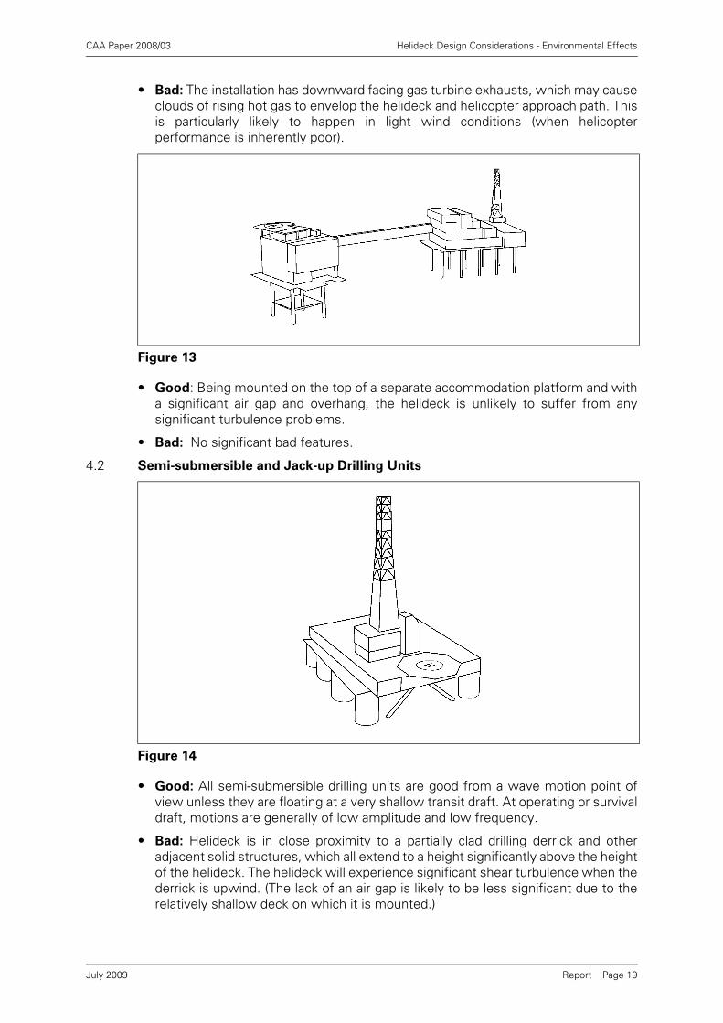
• Bad: The installation has downward facing gas turbine exhausts, which may causeclouds of rising hot gas to envelop the helideck and helicopter approach path. Thisis particularly likely to happen in light wind conditions (when helicopterperformance is inherently poor).
• Good: Being mounted on the top of a separate accommodation platform and witha significant air gap and overhang, the helideck is unlikely to suffer from anysignificant turbulence problems.
• Bad: No significant bad features.
4.2 Semi-submersible and Jack-up Drilling Units
• Good: All semi-submersible drilling units are good from a wave motion point ofview unless they are floating at a very shallow transit draft. At operating or survivaldraft, motions are generally of low amplitude and low frequency.
• Bad: Helideck is in close proximity to a partially clad drilling derrick and otheradjacent solid structures, which all extend to a height significantly above the heightof the helideck. The helideck will experience significant shear turbulence when thederrick is upwind. (The lack of an air gap is likely to be less significant due to therelatively shallow deck on which it is mounted.)
Figure 13
Figure 14
July 2009

CAA Paper 2008/03 Helideck Design Considerations - Environmental Effects
Report Page 20
Good: Good corner helideck location with significant overhang and air gap. Structuresclose to the helideck are mainly open and porous to the wind. Flare booms for well-test operations are both reasonably distant from the helideck and should be visiblewhen in use.
Bad: No significant bad features.
Good: The example jack-up drilling platform shown here has a helideck with largeoverhang and generous air gap, and it is located higher than most of the solidsuperstructure. Structures above the level of the helideck are generally porous. (Mostjack-up drilling platforms have good helideck locations.)
Bad: No significant bad features
Figure 15
Figure 16
July 2009

CAA Paper 2008/03 Helideck Design Considerations - Environmental Effects
Report Page 21
4.3 Tension Leg Platforms
Good: This tension leg platform (TLP) has a high corner location helideck with an airgap. Also the generally open and porous design of the superstructure will reduce windflow problems. Wave induced motions are generally small for a TLP. They are almostzero in roll, pitch and heave, while the larger surge, sway and yaw motions arenormally at very low frequency.
Bad: The downward pointing gas turbine exhausts directly under the helideck arelikely to result in a cloud of hot gas enveloping the helideck in light wind conditionswhen helicopter performance is inherently poor.
Good: Wave induced motions for this tension leg platform will generally be small.They are almost zero in roll, pitch and heave, while the larger surge, sway and yawmotions are normally at very low frequency.
Bad: The helideck is mounted relatively low on the superstructure and is close to alarge solid construction, which will cause significant turbulence when up wind.Upward facing gas turbine exhaust stacks are insufficiently high to ensure that the hotgas plume will pass above the helicopter flight path.
Figure 17
Figure 18
July 2009

CAA Paper 2008/03 Helideck Design Considerations - Environmental Effects
Report Page 22
4.4 FPSOs
Good: The high location of the helideck and generous air gap mean that it is veryunlikely to suffer from any aerodynamic turbulence, particularly as the vessel usuallyoperates heading into wind.
Bad: The extreme forward location of the helideck means that vessel pitch will beexperienced at the helideck as heave motion and acceleration. The high location ofthe helideck means that vessel roll will be experienced at the helideck as sway motionand acceleration. Pilots also dislike bow-mounted helidecks because of the lack ofvisual cues when landing facing away from the vessel.
Good: A helideck at the stern will experience lesser wave induced motions than if itwere at the bow. It is also reasonably high compared with the bulk of thesuperstructure, and is unlikely to experience severe turbulence even though it willusually be downwind. Pilots will have good visual cues for approach and landing.
Bad: Gas turbine exhausts pointing down over the side may cause clouds of rising hotgas to envelop the helideck and helicopter approach path. This is particularly likely tohappen in light wind conditions when helicopter performance is inherently poor. Theaft superstructure violates the 5:1 falling gradient, and if a shuttle tanker can connectto the stern, it is likely to violate the helideck obstacle-free sector when present.
Figure 19
Figure 20
July 2009

CAA Paper 2008/03 Helideck Design Considerations - Environmental Effects
Report Page 23
Good: The helideck cantilevered over the port side of the vessel gives a clearapproach and overshoot path that is free of obstructions and should be largely clearof turbulence for head winds. There will also be good visual cues for the pilot.
Bad: The highly offset or overhanging helideck location means that vessel roll motionwill be manifest at the helideck as heave motion and, depending on the rollcharacteristics and wave conditions experienced, might severely limit helicopteroperability. A shuttle tanker can connect to the stern of the FPSO, and when presentis likely to violate the helideck obstacle-free sector and the 5:1 falling gradient.
Good: Good visual cues and clear approach path for head winds.
Bad: The helideck is mounted relatively low, and in the wake of the mainsuperstructure. As a result, landing helicopters are likely to experience turbulence,and a sharp reduction in wind speed leading to loss of lift. Any shuttle tankerconnected to the stern of the FPSO will violate the helideck obstacle-free sector andthe 5:1 falling gradient.
Figure 21
Figure 22
July 2009

CAA Paper 2008/03 Helideck Design Considerations - Environmental Effects
Report Page 24
5 Methods of Design Assessment
The environmental effects described in this manual are influenced by the wind andwave conditions experienced by the offshore installation. Clearly these weatherconditions vary from day to day in a largely unpredictable way.
However, wind speeds and wave heights are both amenable to statistical analysis,and data can be obtained which describe their statistical properties. These data canbe used with information about the flow patterns around the platform, and theplatform wave motions to:
• estimate the likely helideck operational downtime,
• locate the helideck in the best location on the installation to minimise helideckdowntime, and
• determine the best compromises between conflicting requirements.
The following sections outline methods of assessing the installation properties (fromexperience, from wind tunnel tests and other modelling methods - see Sections 5.1.1and 5.1.2), the key statistical properties of the offshore ocean climate (Sections 5.2and 5.3), and how they can be used together to estimate operability and inform thedesign process (Section 5.4), and in reporting any likely operating limitations tohelicopter operators (Section 5.5).
5.1 Wind Flow Assessment
5.1.1 Expert Visual Inspection
The main factors that influence the wind flow conditions over the helideck are theprevailing wind direction and the location of the helideck on the installation topsidesrelative to this direction. Ideally, the helideck should be located so that, for theprevailing wind direction, it not downwind of major obstructions such as drillingderricks and gas turbine exhausts. In this way, for the majority of the time, theturbulent wake flows and high temperature gas plumes will be blown away from thehelideck and away from the helicopter’s flight path.
Assessment can be made in a qualitative manner by expert review of the installationtopsides and helideck design in conjunction with information on the prevailing winddirections. This may be appropriate in the very early stages of design, and it may bepossible to make an upper estimate of the helideck downtime on this basis. However,in most cases it is preferable to obtain a quantitative measure using flow assessment(Section 5.1.2), the wind climate (Sections 5.2 and 5.3), and a calculation of thehelideck downtime (Section 5.4).
5.1.2 Detailed Flow Modelling using Wind Tunnels and/or Computational Fluid
Dynamics (CFD)
Wind tunnel testing and CFD are the principal tools available for predicting the flowfield around a helideck.
5.1.2.1 Wind Tunnel Tests
The main objectives of wind tunnel tests in the context of helideck design are topredict the mean velocity and turbulence intensity components as well as the meanand peak temperature rises for a range of wind angles and heights above the helideck.A comparison of the results with the design guidance can then be made.
The model scale should be sufficiently large to incorporate an adequate level ofgeometrical detail to reproduce the correct local flow features around the platform.Typical model scales that can achieve this are in the range of 1:100 to 1:200. At thesescales the discrepancies in flow patterns between full-scale and model-scale aregenerally small.
July 2009

CAA Paper 2008/03 Helideck Design Considerations - Environmental Effects
Report Page 25
The model scale should, however, be sufficiently small to minimise the blockage ofthe wind tunnel flow by the model. A high blockage would result in the airflow overthe platform being adversely affected by the walls of the wind tunnel. It isrecommended that the frontal area of the model should not exceed 10% of the cross-sectional area of the tunnel working section.
The wind tunnel should accurately simulate boundary layer velocity and turbulenceprofiles representative of the full-scale marine atmospheric wind flow. Target profilesoften used in offshore studies have been defined by a number of regulatory bodies,e.g. NMD [10], API [11], and SNAME [12]. Wind tunnels designed to simulateatmospheric boundary layers tend to have very long working sections to enable theboundary layer to be developed and controlled. Such wind tunnels should also have areasonable length of working section continuing downstream of the model to enablemeasurements of decaying temperature or turbulence to be made at least oneplatform diameter downwind.
In modelling buoyant hot gas plumes, it is necessary to match the ratios of theexhaust density to ambient density, the exhaust velocity to wind speed and the plumeinertia force to gravitational force, this to maintain similarity between the model scaleand full-scale exhausts. The latter ratio links velocity with buoyancy and implies thatthe model test velocities have to be scaled as the square root of the model scale(Froude scaling). For example, for a model scale of 1:100, a full-scale wind speed of10 m/s is represented by a model test wind speed of 1 m/s. This scaling requirementimposes a practical limit on the model scale for a specific wind tunnel facility, and theability to run at low speeds with good stability is often important.
In circumstances where model scales greater than 1:200 are called for, alternativescaling techniques would be necessary. Such techniques are specific to the particularstudy and specialist advice would be required.
The correct density ratio can be achieved in two ways. Heated air can be used wherethe model release temperature is equal to the full-scale temperature. There arepractical disadvantages associated with this method in setting the high temperaturesof around 500°C in a wind tunnel. A practical alternative is to release a buoyant gasmixture (e.g. helium-air) at ambient temperature with a density equal to that of thefull-scale exhaust plume. The local density decay of the gas mixture is used as a directanalogue of the temperature decay. Any gas mixture can be used provided that thereis a convenient way to measure its concentration.
The measurement of wind speeds above the helideck should be carried out usinginstrumentation capable of resolving velocity and turbulence components. Hot wireanemometry is the most widely used technique although laser anemometry is analternative.
5.1.2.2 Computational Fluid Dynamics
CFD methods allow engineers to model the behaviour of three-dimensional,turbulent, fluid flows by computer. The fundamental aim of CFD is the solution ofequations representing the conservation of mass, fluid momentum and energy,throughout a computational domain which contains a geometrical model of the objectof interest (e.g. an offshore platform), and is contained within boundaries upon whichknown values or behaviours of the flow can be defined (boundary conditions).
Solutions are achieved within a defined computational domain using numericaltechniques. Among commercially available CFD computer programs, the so-calledfinite volume method has become the most popular, mainly for reasons ofcomputational speed, versatility and robustness compared to other numericaltechniques. As its name suggests, the domain of interest is sub-divided into many
July 2009

CAA Paper 2008/03 Helideck Design Considerations - Environmental Effects
Report Page 26
smaller volumes or elements to form a three-dimensional grid. Volume-averagedvalues of fluid variables are located at points within this grid, and local numericalapproximations to the conservation equations used to form a very large system ofcoupled, simultaneous equations. When known boundary conditions are applied,these equations can be solved to obtain averaged quantities for each variable at everygrid point in the flow domain.
The extent of the computational domain should be sufficiently large to avoid anynumerical influence of the boundaries on the flow around the platform in accordancewith best practice guidelines [13]. Typically, this should extend several platformdiameters away from the object of interest in all directions with an extendedcomputational domain in the downstream wake region. A marine atmosphericboundary layer profile of velocity and turbulence should be generated at the upstreamboundary and maintained throughout the computational domain using suitableroughness properties for the sea.
To obtain good quality CFD solutions, a sufficient number of finite volumes (griddensity) must be used, and their quality must be such that the numericalapproximations used retain their formal mathematical accuracy. The grid densityshould be sufficient to fit both geometrical features and flow behaviour (such as shearlayers and eddies). The overall aim is to achieve, as closely as practicable, so-calledgrid-independent solutions of the numerical formulations of the mass, momentumand energy conservation equations. This becomes more difficult, of course, as theReynolds Number and the range of geometrical scales is increased.
Many engineering flows, including platform aerodynamics, are dominated by theeffects of turbulence. There is no single turbulence model that applies universally toall flows. However, there are a number of approaches for engineering applicationsthat have known ranges of validity and can be used with good judgement. It is,nevertheless, best practice to validate CFD results by comparison with physicalmeasurements, or to follow procedures that have been established as valid in thisway [13].
Direct Numerical Simulation (DNS) and Large Eddy Simulation (LES) techniques haveshown potential to predict turbulence with reasonable accuracy but are not yetpractical for helideck design due to the excessive computing power and simulationtime required. The most common approach is to use a Reynolds-Averaged Navier-Stokes (RANS) turbulence model in which time-averaged (or occasionally ensembleaveraged, for transient flows) values of the flow quantities are solved. The role of theturbulence model is twofold. Firstly, it modifies the mean flow field velocities,pressures and temperatures, and secondly it provides a measure of the turbulencewithin the flow. Most commonly, this takes the form of the turbulent kinetic energyand the dominant length or time scale of the energy containing eddies. Both can bedirectly related to simple statistical properties of the turbulence.
5.1.2.3 Strengths and Weaknesses of the Modelling Techniques
Both CFD and wind tunnel testing can provide key information for the design ofoffshore helidecks. The main strengths and weaknesses of each can be summarisedas (assuming best practice in each case):
• On balance, wind tunnel tests can provide reliable turbulent flow data for the safedesign of helidecks, whereas CFD is a tool best employed to provide data on hotexhaust gas dispersion and mean flow quantities.
• Wind tunnel testing will give, directly, measured data for turbulent fluctuations,such as peak values, necessary for comparison with helideck design guidance.
July 2009

CAA Paper 2008/03 Helideck Design Considerations - Environmental Effects
Report Page 27
• Extracting quality estimates for turbulence data from CFD requires specialistexpertise in application and interpretation.
• Wind tunnel tests for helideck wind flows are normally not affected by modellingat small model scale (Reynolds Number effects), but care should be taken toensure that this is the case and to suitably condition the experiments if necessary.
• CFD can provide results at full-scale flow conditions and hence consistently modelbuoyancy (Froude Number) and turbulence (Reynolds Number) effects.
• Although some comparisons with full-scale measurements have been made,neither technique can be said to have been fully validated at full scale.
• CFD results are available for the entire flow field. Wind tunnel data is available atthe instrumented measurement locations, although a large number ofmeasurements can be obtained in a relatively short period of time.
• When CFD is used without sufficient training and experience of the problem inhand, poor quality spurious results are easy to achieve, and the accessibility of thistool makes this, perhaps, more likely than with wind tunnel testing.
5.1.3 Helideck Environment Report Contents
The helideck environment report should contain the following information as aminimum:
5.1.3.1 Wind Tunnel Report
• Details of model design and construction including reasoning for the choice ofmodel scale and associated scaling parameters for replicating full-scale flowconditions.
• Details of wind tunnel set-up, instrumentation, instrument calibration, model set-up and data acquisition system.
• Details of the atmospheric boundary layer simulation and comparison of meanvelocity and turbulence intensity profiles above sea level with standard targetmarine profiles (e.g. ESDU, NMD [10]). Measurements should be obtained at themodel position without the model installed.
• Details of scaling techniques used and experimental conditioning applied toachieve similarity with full-scale, e.g. enhanced model roughness to achieveReynolds Number similarity.
• Tabular and graphical presentation of measured data in accordance with therecommendations of the helideck design guide (see Section 5.5).
• Conclusions and recommendations to mitigate any adverse conditions that mayimpact on helicopter operations.
5.1.3.2 Computational Fluid Dynamics Report
• Details of the CFD model with reasoning for the choice of computational domain,geometrical simplifications, computational mesh, modelling assumptions, sub-models (e.g. turbulence model, bulk resistance terms) and range of validity of thesub-models employed.
• Details of boundary conditions including the atmospheric boundary layer at theinlet, heat sources and surface roughness parameters (e.g. sea and platformsurfaces).
• Comparison of the atmospheric boundary layer profiles of mean velocity andturbulence intensity above sea level with standard target marine profiles (e.g.ESDU, NMD [10]). The profile should be taken at a location approximately onefacility length downstream of the upwind boundary.
July 2009

CAA Paper 2008/03 Helideck Design Considerations - Environmental Effects
Report Page 28
• Demonstration of adequate mesh independence through grid resolution sensitivitytests.
• Demonstration of adequate convergence of the final steady-state solution oriterative transient solution at each time step.
• Tabular and graphical presentation of the simulations in accordance with therecommendations of the helideck design guide (see Section 5.5).
• Conclusions and recommendations to mitigate any adverse conditions that mayimpact on helicopter operations.
5.2 Wind Climate
The wind climate is a description of the probability of experiencing certain windspeeds and directions. It can be used to determine quickly if the wind climate isbenign or harsh, and if there are any strongly prevailing wind directions.
The severity of the wind climate is important because, the more severe, then themore likely that turbulence and hot gasses from high exhaust stacks will be aproblem. In benign climates turbulence is unlikely to be a problem but hot gasesmight still be a hazard, especially if downward facing exhausts have been utilised.
An example set of wind speed /direction frequency statistics is shown in Table 1.
The example is for a Northern European location, and it should be noted that differentgeographic locations are likely to have very different wind speed and directiondistributions. The entries in the table represent percentage annual duration for eachwind direction and wind speed interval. In this case, the most probable wind directionis south with a total duration of 16.5%. This means that for 16.5% of the year, or 60days, the winds will be from the southern sector.
Table 1 Example wind speed/direction frequency table
Beaufort
numberWind direction (from)
N NE E SE S SW W NW Var Total
0 0+ 0+ 0+ 0+ 0+ 0+ 0+ 0+ 0.3 0.5
1 0.2 0.1 0.1 0.1 0.1 0.1 0.2 0.2 0.5 1.5
2 0.9 0.8 0.7 0.6 0.8 0.6 1.2 1.0 0.2 7.0
3 2.1 1.3 1.3 1.5 2.1 2.3 2.5 2.4 0+ 15.5
4 2.8 1.5 1.5 2.0 3.4 3.2 3.0 3.6 21.1
5 2.7 1.0 1.8 2.3 4.2 3.6 3.4 3.5 22.5
6 1.8 0.6 1.6 2.1 3.4 3.3 2.7 2.5 18.0
7 0.9 0.2 1.1 1.3 1.8 2.0 1.4 1.1 9.8
8 0.3 0.1 0.5 0.5 0.6 0.6 0.4 0.4 3.3
9 0+ 0+ 0.1 0.1 0.1 0.1 0.1 0.1 0.7
10 0+ 0+ 0+ 0+ 0+ 0+ 0.1
11 0+
12
Total 11.6 5.7 8.8 10.5 16.5 16.1 14.9 14.9 1.0 100
July 2009

CAA Paper 2008/03 Helideck Design Considerations - Environmental Effects
Report Page 29
The right hand column also shows that this is a relatively severe wind climate withthe wind speed (expressed here as Beaufort number) being at Beaufort 7 or above forabout 14% of the time. This information is sometimes presented graphically in theform of a wind rose (see Figure 23).
5.3 Prevailing Wind Direction
The wind frequency table or the wind rose can be used to identify the prevailing winddirections. These may be defined as the highest probability directions with acombined probability of occurrence of approximately 50%. For example, taking thedata in Table 1, the directional sectors can be ranked as follows:
The prevailing wind directions are therefore defined to be in the range 157.5° to292.5° with a cumulative probability of 47.5% (or 173 days in the year).6
Figure 23 Example wind rose presentation of Table 1
Table 2 Prevailing wind directions
Wind Direction (from) Probability Cumulative
South (157.5° – 202.5°) 16.5% 16.5%
South-West (202.5° – 247.5°) 16.1% 32.6%
West (247.5° – 292.5°) 14.9% 47.5%
North-West (292.5° – 337.5°) 14.9% 62.4%
6. It should be noted that wind directions are invariably defined in terms of the direction that the wind blows FROM.However, occasionally such data may be presented as directions TO (often to be consistent with wave direction datawhich is usually presented in this way). If there is any doubt about the direction definition then it is essential to checkwith the authority that generated or published it. An error of 180° in determining the prevailing wind directions is likely tobe disastrous for helideck operability.
July 2009
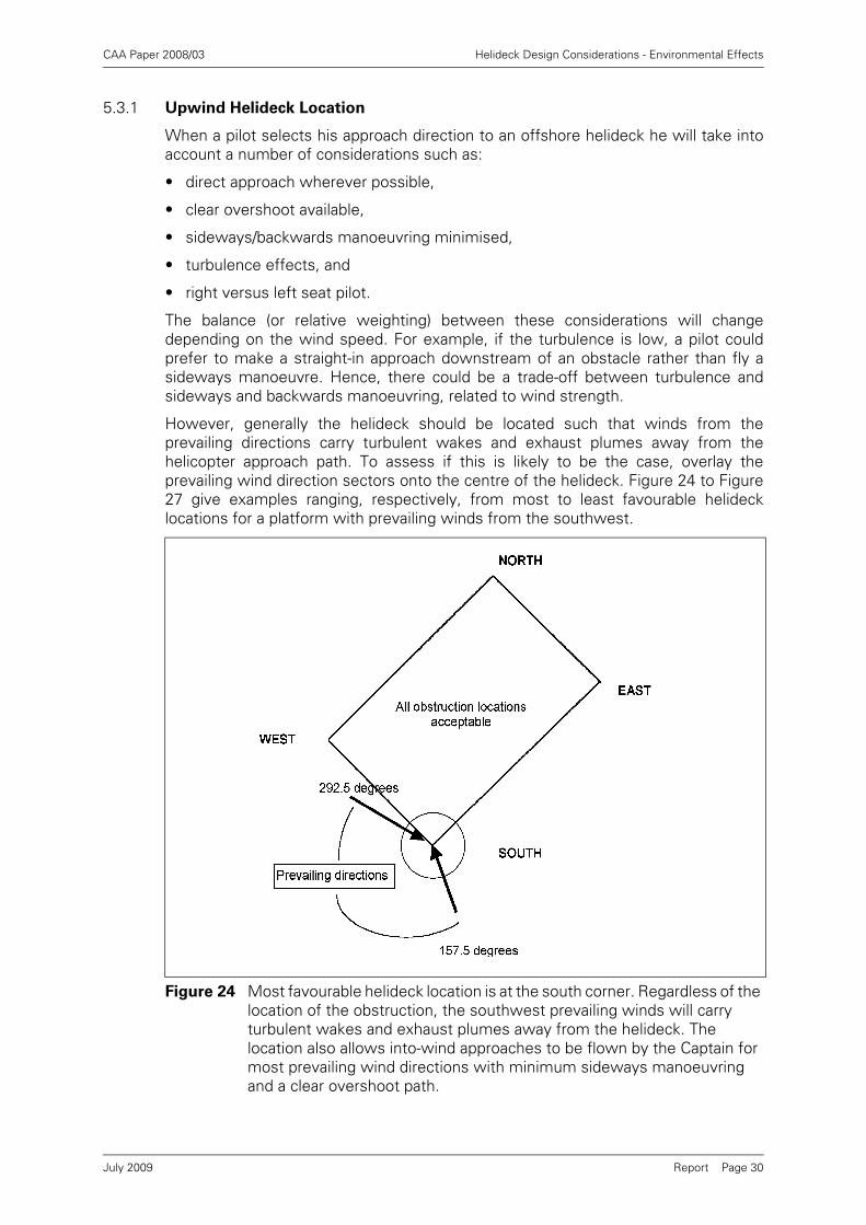
CAA Paper 2008/03 Helideck Design Considerations - Environmental Effects
Report Page 30
5.3.1 Upwind Helideck Location
When a pilot selects his approach direction to an offshore helideck he will take intoaccount a number of considerations such as:
• direct approach wherever possible,
• clear overshoot available,
• sideways/backwards manoeuvring minimised,
• turbulence effects, and
• right versus left seat pilot.
The balance (or relative weighting) between these considerations will changedepending on the wind speed. For example, if the turbulence is low, a pilot couldprefer to make a straight-in approach downstream of an obstacle rather than fly asideways manoeuvre. Hence, there could be a trade-off between turbulence andsideways and backwards manoeuvring, related to wind strength.
However, generally the helideck should be located such that winds from theprevailing directions carry turbulent wakes and exhaust plumes away from thehelicopter approach path. To assess if this is likely to be the case, overlay theprevailing wind direction sectors onto the centre of the helideck. Figure 24 to Figure27 give examples ranging, respectively, from most to least favourable helidecklocations for a platform with prevailing winds from the southwest.
Figure 24 Most favourable helideck location is at the south corner. Regardless of the location of the obstruction, the southwest prevailing winds will carry turbulent wakes and exhaust plumes away from the helideck. The location also allows into-wind approaches to be flown by the Captain for most prevailing wind directions with minimum sideways manoeuvring and a clear overshoot path.
July 2009

CAA Paper 2008/03 Helideck Design Considerations - Environmental Effects
Report Page 31
Figure 25 Second most favourable helideck location is at the west corner. Like the south location, prevailing winds will carry turbulent wakes and exhaust plumes away from the helideck. However, the location will require extensive sideways manoeuvring on approach for many prevailing wind directions.
Figure 26 Third most favourable helideck location is at the east corner. About half the prevailing wind directions will carry turbulent wakes towards the helideck. The location permits clear into-wind approaches to be flown but many prevailing wind directions will have an obstructed overshoot path.
July 2009

CAA Paper 2008/03 Helideck Design Considerations - Environmental Effects
Report Page 32
Major items of obstruction, including drilling derricks and exhaust stacks should beoutside the areas embraced by these sectors as shown in the figures. If they are, thenconditions at the helideck are likely to be compliant for 50% of the time. Ifobstructions are located within the prevailing wind sectors, then the following optionsshould be explored:
• rotate the platform to adjust the prevailing wind sectors,
• relocate the obstructions, or
• relocate the helideck.
If none of these are successful, then a more detailed assessment is required and anaerodynamic specialist should be consulted.
To minimise the effects for other wind directions, then obstructions should be locatedas far away as possible from the helideck. In the case of the exhaust stacks, theseshould be sufficiently high to ensure that the plumes are above the helicopterapproach path. To achieve this, it is recommended that the exhaust outlets be no lessthan 20-30 m above the helideck.
5.4 Estimating Helideck Downtime due to Wind
The installation flow studies outlined in Section 5.1.2 are likely to identifycombinations of wind speed and direction which result in flow conditions over thehelideck that do not comply with the guidance requirements (1.75m/s StandardDeviation of the vertical component, 2°C temperature rise). Ultimately the windspeed and direction conditions that lead to non-compliant combinations will need tobe communicated to the helicopter operator (see Section 5.5).
Figure 27 Least favourable helideck location is at the north corner. Like the east location, about half the prevailing wind directions will carry turbulent wakes towards the helideck. The location permits clear into-wind approaches to be flown but many prevailing wind directions will have an obstructed overshoot path.
July 2009
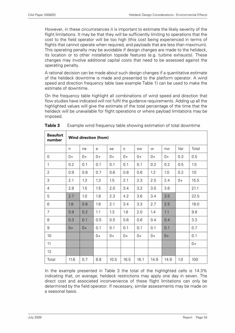
CAA Paper 2008/03 Helideck Design Considerations - Environmental Effects
Report Page 33
However, in these circumstances it is important to estimate the likely severity of theflight limitations. It may be that they will be sufficiently limiting to operations that thecost to the field operator will be too high (this cost being experienced in terms offlights that cannot operate when required, and payloads that are less than maximum).This operating penalty may be avoidable if design changes are made to the helideck,its location or to other installation topside features (e.g. turbine exhausts). Thesechanges may involve additional capital costs that need to be assessed against theoperating penalty.
A rational decision can be made about such design changes if a quantitative estimateof the helideck downtime is made and presented to the platform operator. A windspeed and direction frequency table (see example Table 1) can be used to make theestimate of downtime.
On the frequency table highlight all combinations of wind speed and direction thatflow studies have indicated will not fulfil the guidance requirements. Adding up all thehighlighted values will give the estimate of the total percentage of the time that thehelideck will be unavailable for flight operations or where payload limitations may beimposed.
In the example presented in Table 3 the total of the highlighted cells is 14.3%indicating that, on average, helideck restrictions may apply one day in seven. Thedirect cost and associated inconvenience of these flight limitations can only bedetermined by the field operator. If necessary, similar assessments may be made ona seasonal basis.
Table 3 Example wind frequency table showing estimation of total downtime
Beaufort
numberWind direction (from)
n ne e se s sw w nw Var Total
0 0+ 0+ 0+ 0+ 0+ 0+ 0+ 0+ 0.3 0.5
1 0.2 0.1 0.1 0.1 0.1 0.1 0.2 0.2 0.5 1.5
2 0.9 0.8 0.7 0.6 0.8 0.6 1.2 1.0 0.2 7.0
3 2.1 1.3 1.3 1.5 2.1 2.3 2.5 2.4 0+ 15.5
4 2.8 1.5 1.5 2.0 3.4 3.2 3.0 3.6 21.1
5 2.7 1.0 1.8 2.3 4.2 3.6 3.4 3.5 22.5
6 1.8 0.6 1.6 2.1 3.4 3.3 2.7 2.5 18.0
7 0.9 0.2 1.1 1.3 1.8 2.0 1.4 1.1 9.8
8 0.3 0.1 0.5 0.5 0.6 0.6 0.4 0.4 3.3
9 0+ 0+ 0.1 0.1 0.1 0.1 0.1 0.1 0.7
10 0+ 0+ 0+ 0+ 0+ 0+ 0.1
11 0+
12
Total 11.6 5.7 8.8 10.5 16.5 16.1 14.9 14.9 1.0 100
July 2009

CAA Paper 2008/03 Helideck Design Considerations - Environmental Effects
Report Page 34
5.5 Presentation of Wind Flow Assessment Results
5.5.1 General
The results of wind flow assessment are used at two quite distinct stages of thedevelopment of an offshore installation design.
Firstly, the results are used in design. They may be used to justify changes to thelayout to the installation superstructure and helideck location, and they may be usedto estimate the future operability of the helideck. This requires detailed tabulationsand plots of the aerodynamic features around the helideck. Section 5.5.2 belowcontains recommended formats for the presentation of these results, and guidanceon the range of different wind conditions and other parameters that should becovered.
Secondly, when the design process is complete, and any changes have been takeninto account, there is a need to summarise and present the data to the helicopteroperators and pilots through HCA. This ultimately needs to be a concise assessmentof the flow modelling results, interpreted in terms of the restrictions that will need tobe placed on flight operations. Section 5.5.3 contains recommended formats for thepresentation of this summary information to operators and pilots.
5.5.2 Presentation of Flow Assessment Results for Design
Data on helideck flow assessment takes a number of different forms, those withdefined limiting criteria being:
• Air temperature data, compared with the 2°C above ambient recommendedlimiting temperature criterion.
• Turbulence intensity, compared with the recommended turbulence criteriondefined as the standard deviation of the vertical airflow velocity, which shall notexceed 1.75m/s.
Although no formal criteria currently exist, it is also sometimes helpful to present:
• Longitudinal velocity data at 25m/s free stream velocity (an indication of the extentof shear in the flow).
There are a number of key issues that should be appreciated when this data ispresented, and is plotted or tabulated in terms of wind heading:
• The convention is that wind headings are always presented in terms of the headingFROM which the wind is blowing. Nevertheless, labelling of tabulations and plotsshould always include the words “wind direction (from)” in order to remove anychance of misunderstanding.
• The heading reference being used (e.g. true, magnetic or platform north) shouldalways be explicit on every tabulation and plot.
• For fixed platforms in the early phases of design it may be convenient and usefulto present results in terms of headings relative to Platform North. However, in laterstages when data is being used in operability assessments, or is being preparedfor the production of a summary for operations (see Section 5.5.3), then it is likelyto be much more useful if presented in terms of True North.
• Installations such as mobile drilling rigs and FPSOs that can change their headingas a result of the weather conditions or for operational purposes, should have theirwind heading data presented relative to their primary axis. Again the direction ofthis primary axis should be explicit.
• In all the above, a small annotated plan view sketch alongside the table or plotshould be used to avoid any possibility of misunderstanding by the reader.
July 2009

CAA Paper 2008/03 Helideck Design Considerations - Environmental Effects
Report Page 35
It is recommended that data is presented at two levels: firstly, a detailed level whichshows quantitatively the parameters of interest in relation to the acceptance criteria(see Table 4, Table 5 and Figure 28 below); secondly, at a simpler summary levelwhich illustrates the extent of non-compliance with the limiting criteria as a functionof wind speed and direction (see Figure 29 and Figure 30).
The tabular presentation of the data should comprise results from a polar survey takenabove the landing spot together with results from lateral surveys. The lateral surveysshould correspond to the worst-case wind directions identified in the polar surveys.Typical examples of a tabular presentation are shown in Table 4 and Table 5.
The tables show results for peak temperature rise at a wind speed of 5 m/s but asimilar format should be used for other parameters. Empty cells evident in the Table4 indicate where it was judged that measurements were not required. This is oftenan easy judgement to make for temperature assessments but less so for turbulence.Consequently for turbulence measurements, a full range of wind directions should betested.
For temperature rise measurements, results should be presented for a range ofreference wind speeds e.g. 5, 10, 15 and 20 m/s. This is because temperature risehas an unpredictable dependence on reference wind speed. In contrast, turbulencecan be re-scaled for any wind speed. For this re-scaling, a reference wind speed of 25m/s, taken to be a practical upper limit for helicopter operation, is suggested.
To supplement the tables, it is recommended that the lateral survey results arepresented also as a contour plot as shown in Figure 28.
To highlight the wind conditions in which design criteria are exceeded it isrecommended that summary data is presented to provide an immediate visualindication. Examples of such presentations for temperature rise and turbulence dataare shown respectively in Figure 29 and Figure 30. In these figures, the radial axis isthe reference wind speed and the circumference axis denotes wind direction (from),with respect to Platform North. The absence of shading indicates compliance with thecriteria.
July 2009

CAA Paper 2008/03 Helideck Design Considerations - Environmental Effects
Report Page 36
NOTE: Empty cells denote where measurements were judged to be unnecessary.
For temperature rise data, similar tables would be included for other wind speeds e.g.10, 15 and 20 m/s
Table 4 Polar scan of 3-second peak temperature rise above landing spot
Wind speed at 10 m = 5 m/s
Wind direction
(from)
(Degrees from
Platform N)
z (m)
5
z (m)
10
z (m)
15
z (m)
20
z (m)
25
z (m)
30 MAX
3-second peak temperature oC
0
15
30 5.2 4.3 8.6 5.9 0.1 0.1 8.6
45 11.8 8.3 9.3 4.1 0.1 0.1 11.8
60 9.7 8.3 8.8 5.5 0.3 0.4 9.7
75 3.4 2.2 5.1 2.2 0.3 0.2 5.1
90
105
120
135
150
165 0.5 0.4 0.3 0.0 0.0 0.0 0.5
180 1.9 1.5 1.6 0.2 0.0 0.0 1.9
195 1.1 1.1 1.0 0.0 0.0 0.0 1.1
210 0.9 0.9 0.7 0.0 0.0 0.0 0.9
225 0.0 0.0 0.0 0.0 0.0 0.0 0.0
240
255
270
285
300
315
330
345
July 2009

CAA Paper 2008/03 Helideck Design Considerations - Environmental Effects
Report Page 37
NOTE: For temperature rise data, similar tables would be included covering theother wind speeds and wind directions where any further local peaks wereidentified.
Table 5 Lateral scan of temperature rise across the landing spot
Wind speed at 10 m = 5 m/s
Wind direction from (degrees from Platform N) = 45
z (m)
0
z (m)
5
z (m)
10
z (m)
15
z (m)
20
z (m)
25
z (m)
30
y (m) 3-second peak temperature rise oC
-25 0.5 1.5 0.2 0.2 0.1 0.2 0.2
-20 0.5 1.0 0.8 0.2 0.1 0.3 0.2
-15 0.7 1.3 3.2 3.9 0.2 0.4 0.2
-10 2.2 4.6 6.7 5.9 3.5 0.3 0.4
-5 4.1 7.9 7.4 8.7 5.2 0.3 0.3
0 5.8 11.8 8.3 9.3 4.1 0.1 0.1
5 2.3 6.5 9.1 8.5 8.3 2.0 0.3
10 1.9 5.0 7.7 10.0 5.4 0.4 0.2
15 0.7 3.4 5.2 6.8 2.7 0.3 0.2
20 0 0.5 3.8 2.3 0.7 0.3 0.2
25 0 0.5 0.5 0.2 0.2 0.2 0.3
+ y
- y
Wind direction
July 2009

CAA Paper 2008/03 Helideck Design Considerations - Environmental Effects
Report Page 38
Figure 28 Plot of 3 second peak temperature rise above landing spot; wind speed at 10 m = 5 m/s; wind direction from (degrees from Platform N) = 45. For temperature rise data, similar charts would be included covering the other wind speeds and wind directions where any further local peaks were identified.
Figure 29 Recommended presentation of temperature data. The radial axis denotes reference wind speed in m/s. The circumference axis denotes wind direction (from), with respect to True North.
July 2009

CAA Paper 2008/03 Helideck Design Considerations - Environmental Effects
Report Page 39
5.5.3 Presentation of Flow Assessment Results for Operations
This section contains recommended formats for the presentation of a summary of thehelideck flow assessment interpreted in terms of the operational restrictions that willneed to be placed on flight operations.
This presentation should be prepared for each installation by a person competent inthe interpretation of the wind flow data in terms of helicopter operations. It shouldthen be submitted to HCA, together with the supporting detailed flow assessmentresults (presented as in Section 5.5.2). It is anticipated that HCA will then review theinformation, make any changes deemed necessary to the summary presentation, andthen issue this summary to the helicopter operators.
It is intended that the presentation should be complementary to the 'Aerad Plate',which currently provides the pilot with concise information on the physical layout ofthe installation, together with navigational and radio frequency information.
The requirements for this information are somewhat different if the installation isfixed at a particular heading, as is the case for fixed jacket platforms, semi-submersible production or drilling platforms, tension leg platforms etc., or if theinstallation is an FPSO or mobile drilling unit which changes its heading according tothe weather and/or operational needs. Consequently two examples are provided. InFigure 31 an example is given of a presentation for a fixed platform, while Figure 32contains an example for an FPSO.
Figure 30 Recommended presentation of turbulence data. The radial axis denotes reference wind speed in m/s. The green shaded area denotes the reference wind speed at which compliance with the critical value is maintained. The circumferential axis denotes wind direction (from), with respect to True North.
July 2009
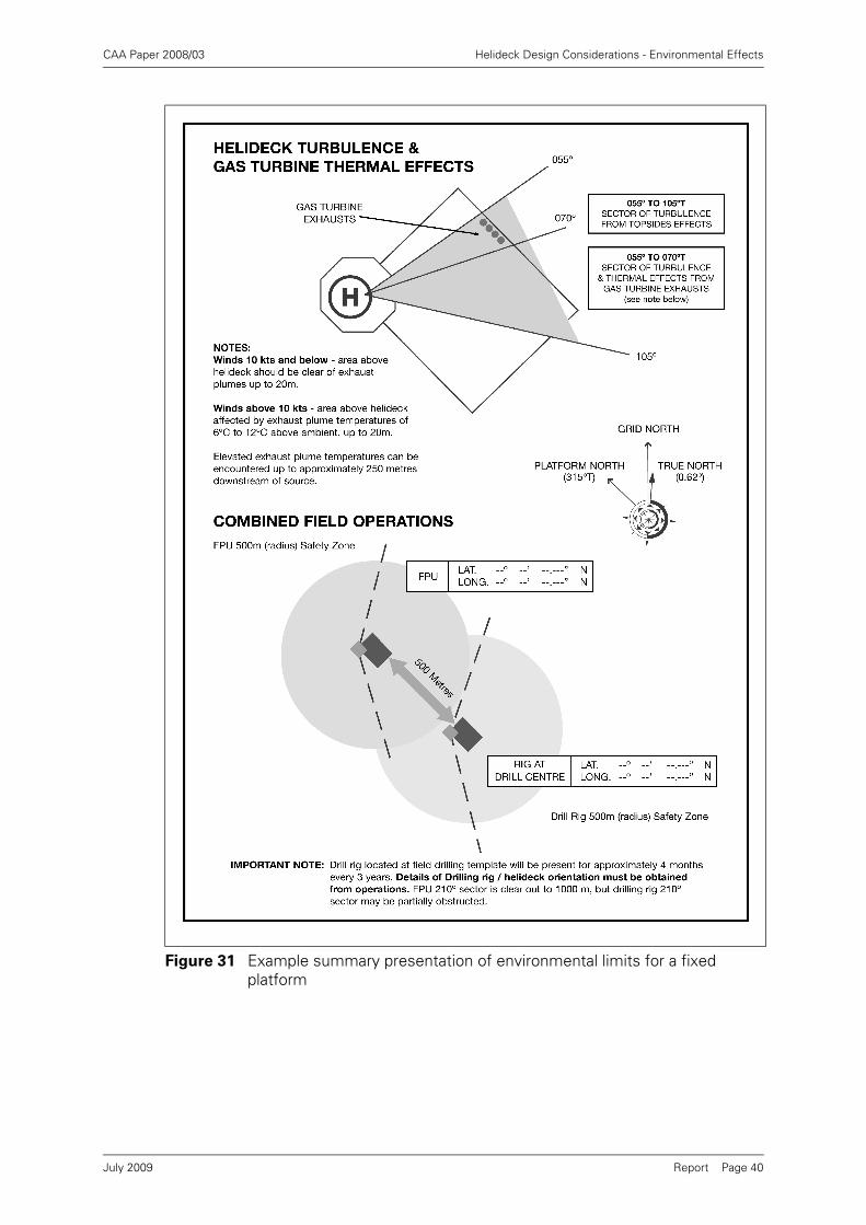
CAA Paper 2008/03 Helideck Design Considerations - Environmental Effects
Report Page 40
Figure 31 Example summary presentation of environmental limits for a fixed platform
July 2009

CAA Paper 2008/03 Helideck Design Considerations - Environmental Effects
Report Page 41
Figure 32 Example summary presentation of environmental limits for an FPSO
July 2009

CAA Paper 2008/03 Helideck Design Considerations - Environmental Effects
Report Page 42
5.6 Wave Motion Assessment
5.6.1 Wave Induced Motion Estimates
The motion characteristics of a vessel or floating platform may be reliably predictedby recourse to well-established computer models, or to physical model testing. Ineither case the results are invariably presented in terms of linear transfer functions.The transfer function contains an amplitude and phase component, and the amplitudeis often referred to as a Response Amplitude Operator (RAO). An example RAO isgiven in Figure 33.
Provided that transfer functions have been derived for all six motion components (roll,pitch, yaw, sway, surge and heave) for a vessel at a defined reference point (often atthe centre of gravity, or amidships at the waterline), then RAOs can be readilycalculated for any helideck location on the vessel.
Using specialist software this data can be combined with wave climate data (seeSection 5.7) and limiting motion criteria (see Section 5.7.1) to derive quantitativehelideck downtime estimates (see Section 5.8).
5.7 Wave Climate
The probability of encountering a given combination of significant wave height andperiod is defined using a 'wave scatter table', which describes the proportion of timewhen the significant wave height and period lie within specified ranges. Wave scattertables for open-water sea areas may be obtained from standard reference texts orcomputer databases (see example in Table 6). Wave scatter tables for specificlocations (especially local in-shore conditions) should be obtained from specialistmetocean sources.
Wave scatter tables defined on an 'all-year', 'all-directions' basis may be adequate forvessels that are to operate at all times of year and whose motions are relativelyinsensitive to heading (e.g. semi-submersible drilling vessels). Wave scatter tables fordirectional sectors are needed in cases where vessel motions vary with relative waveheading (e.g. ships), but the manner of analysis will vary depending on whether thevessel heading is fixed or varies with the direction of the weather. The vessel headingrelative to waves should be considered in cases where the vessel weathervanes, oroperates under heading control (see Section 3.8.6).
Figure 33 Example RAO
July 2009

CAA Paper 2008/03 Helideck Design Considerations - Environmental Effects
Report Page 43
5.7.1 Limiting Motion Criteria
5.7.1.1 General
Limiting motion criteria for landing a helicopter on a floating installation or vessel areat present usually defined in terms of maximum heave, roll and pitch motions. Largeheave motions can make it difficult for the pilot to control the final stages of landingand rate of descent at touchdown, and large accelerations can cause tipping or slidingacross the deck. The motions used in this analysis must represent the motions of thehelideck (rather than the motions of the vessel at its centre of gravity).
The maximum motion experienced during a given time interval depends not only onthe sea state, but also on the particular sequence of waves that occurs, and on thelength of the time interval. Significant variations in maximum motions often occurbetween one sample time interval and another. The limiting motion criteria aretherefore normally interpreted as specifying 'most probable' or 'expected' maximumvalues occurring in a 20-minute time interval (i.e. the most likely or average value ofall maxima that can occur in different randomly-sampled 20-minute intervals).Standard formulae for estimating the most probable and expected maximum motionin a given sea state are available, and are often incorporated into standard vesselmotion prediction programs. Motion time series obtained from time-domainsimulation programs or model tests should be processed statistically to obtainestimates of the most probable or expected maximum values.
Special care should be taken to determine whether maximum motions represent'single-amplitude' (i.e. from the mean value to the maximum) or 'double-amplitude'(i.e. from minimum to maximum) values. Standard helicopter landing criteria areusually defined in terms of maximum double-amplitude heave motions (i.e. measuredfrom trough to peak), but maximum single-amplitude roll and pitch motions (i.e.measured from the true vertical7).
Table 6 Example wave scatter table (from [14])
Worldwide Database, Sea Area 25, Jan - Dec, East
Sig Hgt(m) 28 167 323 278 140 49 13 3 1
OBS
1000
>14
13 to 14
12 to 13
11 to 12
10 to 11
9 to 10
8 to 9 1
7 to 8 1 1 2
6 to 7 1 1 2 1 5
5 to 6 2 4 4 2 1 14
4 to 5 1 7 12 10 5 2 37
3 to 4 5 22 33 24 10 3 1 98
2 to 3 1 19 66 77 44 15 4 1 226
1 to 2 5 62 140 112 46 12 2 381
0 to 1 21 80 85 38 9 2 235
<4 4-5 5-6 6-7 7-8 8-9 9-10 10-11 11-12 12-13 >13
Zero Crossing Period (s)
July 2009

CAA Paper 2008/03 Helideck Design Considerations - Environmental Effects
Report Page 44
5.7.1.2 Heave Criterion
The industry is presently moving from a heave limit to a heave rate limit. Heave rateis considered a more appropriate parameter in the context of the helicoptertouchdown on the helideck, and its implementation will be facilitated by the provisionof electronic motion sensing systems needed to provide the new scheme forassuring on-deck stability described below. It is therefore likely that the switch toheave rate will coincide with the introduction of the new scheme.
Currently, heave rate is calculated by estimating the Maximum average Heave RateMHR (in m/s) based on measurements of the (peak-to-trough or double amplitude)maximum heave, hmax, and the associated heave period, Th. Calculation of the heaveperiod, however, can be problematic at low values of heave. This measure istherefore to be replaced with the Significant Heave Rate (SHR in m/s) defined as theaverage of the highest one-third of heave rate amplitudes recorded during theprevious 20 minutes. The calculation of the new SHR does not rely on themeasurement of heave period and produces very similar numerical results to theoriginal MHR.
SHR = significant heave rate amplitude, defined as the average of the highest one-third of heave rate amplitudes recorded during the previous 20 minutes
NOTE: No change to an existing MHR limit is required when switching to SHR.
5.7.1.3 Helicopter On Deck Stability
A new approach to regulating the safety of helicopter operations to moving helidecksis currently being developed [15]. In the new scheme the existing pitch, roll and heave/ heave rate measurements are retained to determine whether the helideck motionsare acceptable for the helicopter to safely alight on the helideck. Helideck acceleration(motion severity index or MSI) and wind criteria (wind severity index or WSI) havebeen added, however, to ensure the stability of the helicopter once landed on thehelideck.
The acceleration criterion (MSI) is based on a measure of motion severity (MMS),which is simply the acceleration in the plane of the helideck divided by theacceleration normal to the helideck. It can be stated mathematically as:
where: xddot is the total surge acceleration (including gravitational componentdue to pitch), in the plane of the deck
yddot is the total sway acceleration (including gravitational componentdue to roll), in the plane of the deck
zddot is the total acceleration (including gravity) normal to the deck
This measure is monitored on a continuous basis over a 20-minute period andfactored to produce a prediction of the most likely maximum value during the next 20minutes:
MSI(t) = MMSmax(t - 20min, t).R
where R is a constant ≥1. Guidance on the choice of value for R is to be provided bythe CAA.
7. Note that the single-amplitude roll and pitch motions must be measured from the true vertical in order that any vessel listor trim is properly accounted for.
MMSxddot
→⎯⎯yddot
→⎯⎯+
zddot→⎯⎯=
xddot( )2 yddot( )2+
zddot=
July 2009

CAA Paper 2008/03 Helideck Design Considerations - Environmental Effects
Report Page 45
The Motion Severity Index or MSI is then given by8:
MSI = 10 · tan-1(MSI(t))
When the new criterion is introduced the height of the helideck above the vesselcentre of gravity will be of greater concern since the greater this distance, the greaterthe horizontal acceleration generated by a given roll motion.
The limits of operability for the new scheme are defined in terms of a wind severityindex (WSI) as well as the MSI. Both the wind drag forces acting on the helicopter andthe main rotor lift are functions of the wind speed, the wind direction in the plane ofthe deck and the angle of the wind relative to the plane of the rotor disc. Althoughthere are many wind-related parameters that affect the stability of the helicopter, it isnot practical to use more than one parameter to describe the effect of the wind. Forthis reason, all the effects of wind are accounted for in the calculation of the operatinglimits as a function of the mean wind speed. No forecasting factor (such as R usedfor the MSI) is needed.
The WSI is simply the 10-minute mean wind speed at 3m above helideck level.
where Hd is the helideck height, and Umeas corresponds to the measured wind speedat a height Hmeas.
The WSI is to be measured in knots, but displayed as a unit-less number.
Helicopter operating limits are then to be defined in terms of a plot of maximumpermitted MSI value as a function of the WSI value. A generic limits plot is shown inFigure 34 below.
Maximum MSI values may be calculated and analysed using vessel motion modelsand procedures similar to those used to determine maximum heave, roll and pitch,together with the published MSI algorithms.
5.8 Estimating Helideck Downtime due to Waves
Estimates of the likely helideck downtime can be made by combining the informationabout the helideck motion characteristics (RAOs) (see Section 5.6.1) with the
8. The inverse tangent should be calculated in degrees.
Figure 34 Generic form of a MSI/WSI helicopter operating limit
13.0
meas
dmeas10mint H
3mH)(UmeanWSI(t) ⎟⎟⎠
⎞⎜⎜⎝
⎛ +⋅= −
July 2009
CAA Paper 2008/03 Helideck Design Considerations - Environmental Effects
Report Page 46
expected operating wave climate in the scatter table (see Section 5.7) and windclimate (see Section 5.2), and the helideck limiting motion criteria (see section 5.7.1).
The processes are broadly similar to that described for wind in Section 5.4, butestimating the frequency of non-compliance with the new MSI/WSI criteria issignificantly more complex because it involves five parameters (wave height, periodand direction, and wind speed and direction). A rigorous downtime estimation for thenew criteria needs to include the appropriate joint probabilities of wave and windconditions and, unless the vessel heading is fixed, some model describing theoperating policy for the vessel with regard to wind and wave directions. Methodsinvolving the use of hindcast wind/wave data and time domain or event domainsimulation are probably most convenient.
A simpler, less rigorous approach would be to assume a unique wind speed/waveheight relationship and base a statistical estimate on the wave scatter data for theoperating area. In either case the process should be performed by a competent navalarchitect using the appropriate specialised software.
Once the helideck downtime has been estimated, the vessel operator can decidewhether it is at an acceptable level or not. Helideck downtime will lead to disruptionof vessel operations, and these will have a cost. Relocating the helideck to a vessellocation with lesser motions and thus lower downtime may be appropriate, but itshould be borne in mind that for smaller ships the limiting motion criteria may varydepending on the helideck location on the vessel. Lesser motions are permitted forbow mounted helidecks, for example, owing to the poorer visual cues available to thepilot.
July 2009
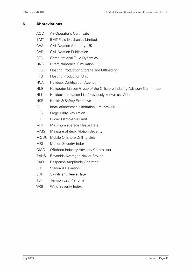
CAA Paper 2008/03 Helideck Design Considerations - Environmental Effects
Report Page 47
6 Abbreviations
AOC Air Operator's Certificate
BMT BMT Fluid Mechanics Limited
CAA Civil Aviation Authority, UK
CAP Civil Aviation Publication
CFD Computational Fluid Dynamics
DNS Direct Numerical Simulation
FPSO Floating Production Storage and Offloading
FPU Floating Production Unit
HCA Helideck Certification Agency
HLG Helicopter Liaison Group of the Offshore Industry Advisory Committee
HLL Helideck Limitation List (previously known as IVLL)
HSE Health & Safety Executive
IVLL Installation/Vessel Limitation List (now HLL)
LES Large Eddy Simulation
LFL Lower Flammable Limit
MHR Maximum average Heave Rate
MMS Measure of deck Motion Severity
MODU Mobile Offshore Drilling Unit
MSI Motion Severity Index
OIAC Offshore Industry Advisory Committee
RANS Reynolds-Averaged Navier-Stokes
RAO Response Amplitude Operator
SD Standard Deviation
SHR Significant Heave Rate
TLP Tension Leg Platform
WSI Wind Severity Index
July 2009

CAA Paper 2008/03 Helideck Design Considerations - Environmental Effects
Report Page 48
7 References
[1] Helideck Design Considerations - Environmental Effects, CAA Paper 2004/02,30th Jan 2004.
[2] Offshore Helicopter Landing Areas - Guidance on Standards. CAP 437 publishedby the CAA, Sixth edition, December 2008.
[3] Helicopter Turbulence Criteria for Operations to Offshore Platforms, CAA Paper2004/03, 22 Sep 2004.
[4] Offshore Helideck Environmental Research - Validation of the HelicopterTurbulence Criterion and Review of the CAP 437 0.9m/s Vertical WindComponent Criterion for Helicopters Operating to Offshore Installations, CAAPaper 2008/02, May 2009.
[5] Helideck Limitation List (HLL), Issued by the Helideck Certification Agency,Issue 01 January 2003. The latest version is available from http://www.helidecks.org.
[6] A questionnaire survey of workload and safety hazards associated with NorthSea and Irish Sea helicopter operations, CAA Paper No. 97009, June 1997.
[7] Visualisation of Offshore Gas Turbine Exhaust Plumes, CAA Paper 2007/02,October 2007.
[8] Research on Offshore Helideck Environmental Issues, CAA Paper 99004,August 2000.
[9] Norsk Helikopter, CHC Helikopter Service AS, Standard Measuring Equipmentfor Helideck Monitoring System (HMS) and Weather Data, Rev4 20032005(7),March 2005.
[10] Norwegian Maritime Directorate: Wind Tunnel Tests Procedure, Regulations forMobile Drilling Platforms, 1999.
[11] American Petroleum Institute: Recommended Practice for Planning, Designingand Constructing Fixed Offshore Platforms, Recommended Practice 2A-WSD(RP2A-WSD), 1993
[12] Society of Naval Architects and Marine Engineers: Guidelines for the WindTunnel Testing of Mobile Offshore Drilling Units, SNAME OC-1 Technical Panel,1988
[13] Casey, M. & Windtergerste, T., ERCOFTAC Special Interest Group on Qualityand Trust in Industrial CFD - Best Practice Guidelines, ERCOFTAC Publication,Version 1.0 Jan 2002.
[14] Global Wave Statistics Online (www.globalwavestatisticsonline.com), BMTFluid Mechanics Limited, December 2001.
[15] Scaperdas, A., Gallagher, P., Developing Safe Operating Limits for HelicoptersLanding on Moving Offshore Platforms, Proceedings of Conference - MaritimeOperations of Rotorcraft, Royal Aeronautical Society, London, June 2008.
July 2009


