41
CAB ™ 16 Series CobraNet ™ Audio Bridge CAB 16i CAB 16o CAB 16d User Manual

CAB™
16 Series
CobraNet™
Audio Bridge
CAB 16i
CAB 16o
CAB 16d
User Manual
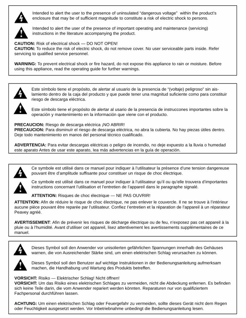
Intended to alert the user to the presence of uninsulated “dangerous voltage” within the product’s enclosure that may be of sufficient magnitude to constitute a risk of electric shock to persons.
Intended to alert the user of the presence of important operating and maintenance (servicing) instructions in the literature accompanying the product.
CAUTION: Risk of electrical shock — DO NOT OPEN!CAUTION: To reduce the risk of electric shock, do not remove cover. No user serviceable parts inside. Refer servicing to qualified service personnel.
WARNING: To prevent electrical shock or fire hazard, do not expose this appliance to rain or moisture. Beforeusing this appliance, read the operating guide for further warnings.
Este símbolo tiene el propósito, de alertar al usuario de la presencia de “(voltaje) peligroso” sin ais-lamiento dentro de la caja del producto y que puede tener una magnitud suficiente como para constituirriesgo de descarga eléctrica.
Este símbolo tiene el propósito de alertar al usario de la presencia de instruccones importantes sobre laoperación y mantenimiento en la información que viene con el producto.
PRECAUCION: Riesgo de descarga eléctrica ¡NO ABRIR!PRECAUCION: Para disminuír el riesgo de descarga eléctrica, no abra la cubierta. No hay piezas útiles dentro.Deje todo mantenimiento en manos del personal técnico cualificado.
ADVERTENCIA: Para evitar descargas eléctricas o peligro de incendio, no deje expuesto a la lluvia o humedadeste aparato Antes de usar este aparato, Iea más advertencias en la guía de operación.
Ce symbole est utilisé dans ce manuel pour indiquer à l’utilisateur la présence d’une tension dangereusepouvant être d’amplitude suffisante pour constituer un risque de choc électrique.
Ce symbole est utilisé dans ce manuel pour indiquer à l’utilisateur qu’il ou qu’elle trouvera d’importantesinstructions concernant l’utilisation et l’entretien de l’appareil dans le paragraphe signalé.
ATTENTION: Risques de choc électrique — NE PAS OUVRIR!
ATTENTION: Afin de réduire le risque de choc électrique, ne pas enlever le couvercle. Il ne se trouve à l’intérieuraucune pièce pouvant être reparée par l’utilisateur. Confiez I’entretien et la réparation de l’appareil à un réparateurPeavey agréé.
AVERTISSEMENT: Afin de prévenir les risques de décharge électrique ou de feu, n’exposez pas cet appareil à lapluie ou à l’humidité. Avant d’utiliser cet appareil, lisez attentivement les avertissements supplémentaires de cemanuel.
Dieses Symbol soll den Anwender vor unisolierten gefährlichen Spannungen innerhalb des Gehäuseswarnen, die von Ausreichender Stärke sind, um einen elektrischen Schlag verursachen zu können.
Dieses Symbol soll den Benutzer auf wichtige Instruktionen in der Bedienungsanleitung aufmerksammachen, die Handhabung und Wartung des Produkts betreffen.
VORSICHT: Risiko — Elektrischer Schlag! Nicht öffnen!VORSICHT: Um das Risiko eines elektrischen Schlages zu vermeiden, nicht die Abdeckung enfernen. Es befindensich keine Teile darin, die vom Anwender repariert werden könnten. Reparaturen nur von qualifiziertemFachpersonal durchführen lassen.
ACHTUNG: Um einen elektrischen Schlag oder Feuergefahr zu vermeiden, sollte dieses Gerät nicht dem Regenoder Feuchtigkeit ausgesetzt werden. Vor Inbetriebnahme unbedingt die Bedienungsanleitung lesen.

GENERAL CAUTIONS AND WARNINGS!
To prevent electrical shock or potential fire hazards, do not expose the CAB 16 to moisture or rain. Before using this product, read the user manuals for further warnings and cautions.
The following cautions should be carefully observed when installing, wiring or using this product:
DO NOT use any other power supply or cable other than the one provided with this unit.
DO NOT remove the top cover of the unit. There are no user serviceable parts inside. Refer serviceto qualified personnel.
DO NOT use solvents or other cleaners to clean the unit. Basic external care requires only a dampcloth. Disconnect the power supply cord before cleaning.
Read all safety and installation instructions and retain all documentation for further reference.
The CAB 16 should be installed so that its mounting position does not interfere with proper venti-lation.
This product should not be installed or placed near a source of heat.
Power supply cords and associated connectors should be unplugged from the power source whenthe unit is not used for long periods of time, or will be stored.
If this product is to be mounted in an equipment rack, install rear support if required by the rackmanufacturer.
Care should be taken to ensure that the installation is clear of possible sources of contamination.Make sure that the product’s ventilation openings are not exposed to possible sources of liquid,gases, or other contaminants.
This product should be inspected by a qualified service technician if the power supply cord or con-nector has been damaged, if the unit has been dropped, or if a foreign substance has gained accessto the interior electronic and electrical components.
The information contained in this manual is subject to change without notice. Peavey Electronics is not liablefor improper installation or configuration. The information contained herein is intended only as an aid toqualified personnel in the design, installation and maintenance of engineered audio systems. The installingcontractor or end user is ultimately responsible for the successful implementation of these systems.
All creative content in this manual, including the layout, art design, content, photography, drawings, specifi-cations and all other intellectual property is Copyright © 2000 Peavey Electronics Corporation, except wherenoted. All rights reserved.
Manual by WR.
Page 4 http://aa.peavey.com copyright 2000 All Rights Reserved
Thank You! 7
What’s In The Box? 7
Covered Products 7
8
Assumptions 8
Installation 9
Hardware vs. Software Devices 10
The Test View 11
Panel Features
Connections
Setting The Hardware Base Address 30
Setting The CobraNet Audio Bundle 31
Testing, Testing..... 32-33
Testing, Testing.....Digital Style! 34-35
Tech Support & Warranty Registration 36
CAB 16i 12
CAB 16i Front Panel 16
CobraNet® 22
Audio 23
CAT 5 cable is your friend.... 26-27
Linking 28
CAB 16i Rear Panel 17
CAB 16o Front Panel 18
CAB 16o Rear Panel 19
CAB 16d Front Panel 20
CAB 16d Rear Panel 21
CAB 16o 13
CAB 16d 14-15
CAB™
16 Series User Manual
Table of Contents
Additional Resources 37
Specifications 38-39
Warranty Statement 40
Linking Examples 29
RS-485 23
S/PDIF 24-25
Software Device Features
Features

Page 5Peavey Electronics Corp.
Table Of Contents
The CAB™ components and their relationships (Figure 1) 10
The CobraNet™ audio transport devices and their control panels (Figure 2) 10
Recommended Test View Configuration (Figure 3) 11
Typical Network Connections (Figure 4) 22
Direct Connection Example (Figure 5) 22
Analog and Digital Audio Connections (Figure 6) 23
RS-485 Serial Data Connections (Figure 7) 23
CAB 16i Link Connection Example (Figure 13) 28
CAB 16o Link Connection Example (Figure 14) 29
Hardware Base Address Switches (Figure 16) 30
Hardware & Software Addressing Controls (Figure 17) 30
CobraNet Input and Output Controls (Bundle Numbers in the OFF position) (Figure 18) 31
CAB Device Audio Bundle Number controls shown in the OFF position. (Figure 19) 31
Test Configuration (CAB 16i, CAB 16o) 32-33
Test Configuration (CAB 16d) 34-35
Illustrations
CAB 16d Link Connection Example (Figure 15) 29
Standard “normal” CAT 5 cable (Figure 9) 26
S/PDIF resistor network configurations (Figure 8) 25
CAT 5 Wire/Connector cross reference chart, standard & crossover cable types (Figure 10) 27
CAT 5 cable and RJ-45 termination details (Figure 11) 27
CAT 5 “crossover” cable (Figure 12) 27
CAB™
16 Series User Manual
Page 6 http://aa.peavey.com copyright 2000 All Rights Reserved
CAUTION!
The CAB 16 Series products are Ethernet (CobraNet™) network products designed to operate on a network back-bone or infrastructure. The design, implementation and maintenance of this infrastructure is critical to the opera-
tion and performance of the CAB 16 Series products. Peavey Electronics does not support nor service network cabling, hubs,switches, patch bays, wall plates, connector panels or any other type of network interconnect device. Please ensure that thesecomponents and their associated installation techniques have been properly designed and installed for CobraNet audio appli-cations.
This manual is written specifically for the CAB 16 Series products built with Firmware Version 2.6.8. Specific functionalityrelating to earlier firmware is not covered in this manual. In the event that your CAB 16 includes an earlier firmware release,you should contact the Peavey Architectural Acoustics Technical Services Group for information on how this may, or may not,impact your installation. Installation or upgrading firmware within the CAB 16 is not covered in this manual.
Several associated products are required to complete a working system using the CAB 16. This manual frequently makes refer-ence to these other products, but does not provide specific configuration or installation information on them. Please refer tothe manuals for these products for information. Every product, both Peavey products and third party devices, must be proper-ly installed for the CAB 16 to operate in accordance with its published specification.
This product is fan cooled with an intake fan on one side of the unit. The exhaust is located on the other side. Do not blockthe fan or any vents when installing this product. Proper cooling is essential to maintain proper operation and long-term sta-bility in this product. Install this product in EIA approved equipment racks only.
The information contained in this manual is subject to change without notice. Peavey Electronics is not liable for improperinstallation or configuration. The information contained herein is intended only as an aid to qualified personnel in the design,installation and maintenance of engineered audio systems. The installing contractor or end user is ultimately responsible forthe successful implementation of these systems.
Welcome
Page 7Peavey Electronics Corp
Thank You! Thank you for purchasing the CAB™ 16 Series CobraNet™ Audio Bridge. Thisproduct is designed to provide years of trouble-free operation, and high qual-ity audio performance. We sincerely hope that you enjoy your new CAB 16Series product, and will find other products in the Peavey ArchitecturalAcoustics product line to supplement your system. We are confident thatyou will find the CAB 16 Series products, as well as other ArchitecturalAcoustics products to be of the highest quality available.
This manual was written to provide as much information as possible foryour new Peavey Architectural Acoustics product. It is our sincere desirethat you enjoy your purchase. We feel that the best way to fully enjoy anypurchase is to have an in-depth understanding of the product’s features,functionality and performance characteristics. We hope that this manual,along with the manuals of our other products, will provide this. If yourequire additional information that this manual does not provide, please letus know. We are always looking for better ways to provide informationabout our products, and your input is always appreciated. If you have acomment about this manual, or would like to make a suggestion, pleasewrite to: Peavey Electronics Corp., Architectural Acoustics Division, 711 ASt., Meridian, MS 39301. Thank you again for using Peavey!
What’s In The Box? The CAB 16 Series products are packaged in a single container. This contain-er includes the following items:
1- CAB 16i, CAB 16o or CAB 16d CobraNet Audio Bridge1- IEC removable power supply line cord
(120VAC Domestic, 230VAC Export)18- 3-screw Euro connectors*1- User Manual/Literature Package
* Asterisk indicates that these items are shipped installed on the CAB 16Series product.
If any of these items are missing, please contact your Authorized PeaveyArchitectural Acoustics contractor/dealer.
Covered Products This User Manual covers the following CAB 16 Series products:
CAB 16i CobraNet Audio Bridge and matching software devices forMediaMatrix. (16 line inputs)
CAB 16o CobraNet Audio Bridge and matching software devices forMediaMatrix (16 line outputs)
CAB 16d CobraNet Audio Bridge and matching software devices forMediaMatrix (8 digital audio (AES3 or S/PDIF) channels in and out)
All of these products have similar feature sets and audio performance charac-teristics. This manual provides information on all products, and the differ-ences are notated within the context of the subject matter. When the topicis common to both units, no differentiation is noted, nor required.
Page 8 http://aa.peavey.com copyright 2000 All Rights Reserved
CAB™
16 Series User Manual
Features
Assumptions
- CobraNet™ ethernet audio transport- Single rack space package- Forced air cooling- Front panel analog audio metering- Front panel network status monitoring- 24 bit D/A and A/D converters- Discreet analog design- Digital control of analog functions- 16 line level inputs (16i only)- 16 line level outputs (16o only)- 8 AES3 or S/PDIF digital audio inputs and outputs (16d only)- Full analog gain stage w/digital control (except 16d)- User defined network hardware address- Removable connectors for audio and external controls- Industry standard RJ-45 connector for connecting to ethernet
CobraNet network- RS-485 port for transporting serial data across the network- Support for stand alone operation
In stand alone applications, the CAB 16 Series is a very powerful tool.Ease of use, external control options and a simple interface make it per-fect for many applications where simple audio transport is required.Among the many applications the CAB 16 Series was designed forinclude:
- Theme Parks- Presentation Rooms- Board Rooms- Courtrooms- Auditorium/Cafetorium- Lecture Hall Sound Reinforcement- Meeting Rooms- Convention Centers- Paging- Background Music- Retail Spaces- Restaurant/Bar Sound
The CAB 16 Series is a prefect choice for many audio applicationswhere transport of audio signal must occur over long distances. Used inconjunction with MediaMatrix products, the CAB 16 Series providesthe highest level of audio systems performance, functionality and con-trol.
The CAB 16 Series of CobraNet Audio Bridges are designed foradvanced MediaMatrix systems. It is assumed that you have a workingknowledge of MediaMatrix hardware and software as well as comput-ers, Windows NT and ethernet networks. If you do not have thisknowledge, please refer the configuration and installation of this prod-uct to qualified personnel. For in-depth information on MediaMatrix,refer to the online help. Additional resources are listed in this manual.

Installation
Page 9Peavey Electronics Corp
Installation The CAB™ 16 Series product is designed to mount in a standard EIA electron-ic equipment rack. Because the CAB 16 includes forced air cooling, addingrack mounted vent panels is not required for most installations. However, itis recommended that common sense be applied to large installations wheremultiple units are mounted in a single rack. It is generally accepted that aratio of 2:1 is a good rule of thumb that usually provides adequate perform-ance. In installations where adverse conditions exist, and room temperaturesare likely to rise, additional vents should be installed.
Do not block the fan or any vents when installing the CAB 16. Proper cool-ing is essential to maintain proper operation and long-term stability in thisproduct.
When dressing off wiring harnesses, take care with CAT 5 cables. Do nottie-wrap bundles of CAT 5 wire too tight. Leave plenty of room for bends,allowing the cable to progress naturally from the RJ-45 connector. Creatingtightly wrapped CAT 5 wire bundles can cause loose crimp joints and defec-tive terminations.
To successfully install your new CAB 16 Series product, and perform thetesting examples contained in this manual, you will need the following com-ponents:
• A MediaMatrix® MiniFrame 208nt-cn or MM™-760nt, MM™-960nt orMM™-980nt Mainframe.
• MWare 3.1.2 or later software.
• PC Monitor, mouse and keyboard.
• At least 1 MM™ DSP-cn CobraNet™ DPU card for MediaMatrix.
• At least 1 CAB 16i and 1 CAB 16o CobraNet™ Audio Bridge, OR 2 CAB 16dCobraNet Audio Bridges.
• At least 1 generic fast ethernet 100 Base T network switch*.
• An assortment of CAT 5 cables.
• An audio source, power amplifier and loudspeaker.
In MediaMatrix, the minimum CobraNet network consists of a singleMediaMatrix frame housing at least one MM DSP-cn CobraNet DPU card,CAB 16i and CAB 16o audio bridge and a single ethernet switch. Of course,most systems will include many more DSP-cn cards and CAB devices, butthis is the most basic configuration.
* The selection of a proper network switch is critical for a successful imple-mentation. Although CobraNet is an ethernet protocol, there are perform-ance issues that must be considered when selecting this switch for use inCobraNet audio systems.
For the latest list of CobraNet compliant products, please refer to PeakAudio’s website at http://www.peak audio.com.
CAB™
16 Series User Manual
Page 10 http://aa.peavey.com copyright 2000 All Rights Reserved
Hardware vs. Software Devices
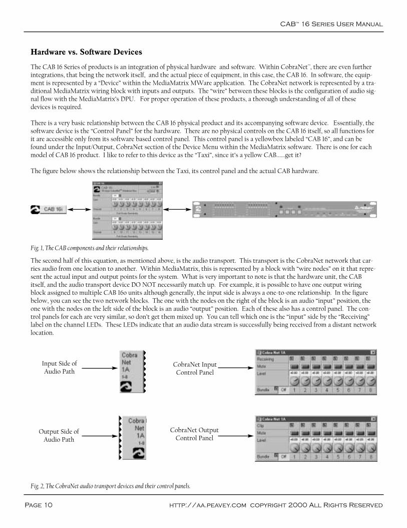
The CAB 16 Series of products is an integration of physical hardware and software. Within CobraNet™, there are even furtherintegrations, that being the network itself, and the actual piece of equipment, in this case, the CAB 16. In software, the equip-ment is represented by a “Device” within the MediaMatrix MWare application. The CobraNet network is represented by a tra-ditional MediaMatrix wiring block with inputs and outputs. The “wire” between these blocks is the configuration of audio sig-nal flow with the MediaMatrix’s DPU. For proper operation of these products, a thorough understanding of all of thesedevices is required.
There is a very basic relationship between the CAB 16 physical product and its accompanying software device. Essentially, thesoftware device is the “Control Panel” for the hardware. There are no physical controls on the CAB 16 itself, so all functions forit are accessible only from its software based control panel. This control panel is a yellowbox labeled “CAB 16”, and can befound under the Input/Output, CobraNet section of the Device Menu within the MediaMatrix software. There is one for eachmodel of CAB 16 product. I like to refer to this device as the “Taxi”, since it’s a yellow CAB......get it?
The figure below shows the relationship between the Taxi, its control panel and the actual CAB hardware.
The second half of this equation, as mentioned above, is the audio transport. This transport is the CobraNet network that car-ries audio from one location to another. Within MediaMatrix, this is represented by a block with “wire nodes” on it that repre-sent the actual input and output points for the system. What is very important to note is that the hardware unit, the CABitself, and the audio transport device DO NOT necessarily match up. For example, it is possible to have one output wiringblock assigned to multiple CAB 16o units although generally, the input side is always a one-to-one relationship. In the figurebelow, you can see the two network blocks. The one with the nodes on the right of the block is an audio “input” position, theone with the nodes on the left side of the block is an audio “output” position. Each of these also has a control panel. The con-trol panels for each are very similar, so don’t get them mixed up. You can tell which one is the “input” side by the “Receiving”label on the channel LEDs. These LEDs indicate that an audio data stream is successfully being received from a distant networklocation.
Fig. 1, The CAB components and their relationships.
Fig. 2, The CobraNet audio transport devices and their control panels.
Input Side ofAudio Path
Output Side ofAudio Path
CobraNet InputControl Panel
CobraNet OutputControl Panel
Hardware & Software
Page 11Peavey Electronics Corp
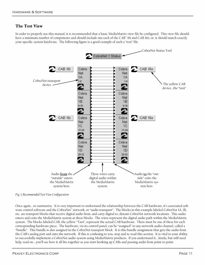
The Test View
In order to properly use this manual, it is recommended that a basic MediaMatrix view file be configured. This view file shouldhave a minimum number of components and should include one each of the CAB™ 16i and CAB 16o, or, it should match exactlyyour specific system hardware. The following figure is a good example of such a “test” file.
Once again....to summarize. It is very important to understand the relationship between the CAB hardware, it’s associated soft-ware control software and the CobraNet™ network, or “audio transport”. The blocks in this example labeled CobraNet 1A, 1B,etc. are transport blocks that receive digital audio from, and carry digital to, distant CobraNet network locations. This audioenters and exits the MediaMatrix system at these blocks. The wires represent the digital audio path within the MediaMatrixsystem. The blocks labeled CAB, the yellow “Taxi”, represent the actual CAB hardware. There must be one of these for eachcorresponding hardware piece. The hardware, via its control panel, can be “assigned” to any network audio channel, called a“bundle”. This bundle is also assigned in the CobraNet transport block. It is this bundle assignment that gets the audio fromthe CAB’s analog port and onto the network. If this is confusing to you, stop and re-read this section. It is vital to your abilityto successfully implement a CobraNet audio system using MediaMatrix products. If you understand it....kinda, but still needhelp, read on....you’ll see how it all fits together as you start hooking up CABs and passing audio from point to point.
Fig. 3, Recommended Test View Configuration
CobraNet Status Tool
The yellow CABdevice...the “taxi”
CobraNet transportdevice
Audio from the“outside” enters
the MediaMatrixsystem here.
These wires carrydigital audio within
the MediaMatrixsystem.
Audio to the “out-side” exits the
MediaMatrix sys-tem here.
CAB™
16 Series User Manual
Page 12 http://aa.peavey.com copyright 2000 All Rights Reserved
CAB 16i Software Device Features
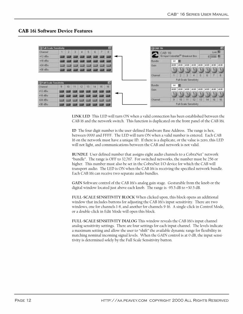
LINK LED This LED will turn ON when a valid connection has been established between theCAB 16 and the network switch. This function is duplicated on the front panel of the CAB 16i.
ID The four digit number is the user-defined Hardware Base Address. The range is hex,between 0000 and FFFF. The LED will turn ON when a valid number is entered. Each CAB16 on the network must have a unique ID. If there is a duplicate, or the value is zero, this LEDwill not light, and communications between the CAB and network is not valid.
BUNDLE User defined number that assigns eight audio channels to a CobraNet™ network“bundle”. The range is OFF to 32,767. For switched networks, the number must be 256 orhigher. This number must also be set in the CobraNet I/O device for which the CAB willtransport audio. The LED is ON when the CAB 16i is receiving the specified network bundle.Each CAB 16i can receive two separate audio bundles.
GAIN Software control of the CAB 16i’s analog gain stage. Gesturable from the knob or thedigital window located just above each knob. The range is -95.5 dB to +30.5 dB.
FULL-SCALE SENSITIVITY BLOCK When clicked upon, this block opens an additionalwindow that includes buttons for adjusting the CAB 16i’s input sensitivity. There are twowindows, one for channels 1-8, and another for channels 9-16. A single-click in Control Mode,or a double-click in Edit Mode will open this block.
FULL-SCALE SENSITIVITY DIALOG This window reveals the CAB 16i’s input channelanalog sensitivity settings. There are four settings for each input channel. The levels indicatea maximum setting and allow the user to “shift” the available dynamic range for flexibility inmatching nominal incoming signal levels. When the GAIN control is at 0 dB, the input sensi-tivity is determined solely by the Full Scale Sensitivity button.

Software Features
Page 13Peavey Electronics Corp
CAB 16o Software Device Features
LINK LED This LED will turn ON when a valid connection has been established between theCAB™ 16 and the network switch. This function is duplicated on the front panel of the CAB16o.
ID The four digit number is the user-defined Hardware Base Address. The range is hex,between 0000 and FFFF. The LED will turn ON when a valid number is entered. Each CAB16 on the network must have a unique ID. If there is a duplicate, or the value is zero, this LEDwill not light, and communications between the CAB and network is not valid.
BUNDLE User defined number that assigns eight audio channels to a CobraNet™ network“bundle”. The range is OFF to 32,767. For switched networks, the number must be 256 orhigher. This number must also be set in the CobraNet I/O device for which the CAB willtransport audio. The LED is ON when the CAB 16o is transmitting the specified networkbundle. Each CAB 16o can transmit (send) two separate audio bundles.
MUTE This single button will mute all audio outputs in the digital domain. This button isindependent of the output GAIN control.
GAIN Software control of the CAB 16o’s analog output stage. Gesturable from the knob orthe digital window located just above each knob. The range is -95.5 dB to +30.5 dB.
FULL-SCALE SENSITIVITY BLOCK When clicked upon, this block opens an additionalwindow that includes buttons for adjusting the CAB 16o’s output scale. There are two win-dows, one for channels 1-8, and another for channels 9-16. A single-click in Control Mode, or adouble-click in Edit Mode will open this block.
FULL-SCALE SENSITIVITY DIALOG This window reveals the CAB 16o’s output channelanalog settings. There are four settings for each output channel. The levels indicate a maxi-mum setting and allow the user to “shift” the available dynamic range for flexibility in match-ing the input sensitivity of the power amplifier input. When the GAIN control is at 0 dB, theinput sensitivity is determined solely by the Full Scale Output button.

CAB™
16 Series User Manual
Page 14 http://aa.peavey.com copyright 2000 All Rights Reserved
LINK LED This LED will turn ON when a valid connection has been established between theCAB 16 and the network switch. This function is duplicated on the front panel.
ID The four digit number is the user-defined Hardware Base Address. The range is hex,between 0000 and FFFF. The LED will turn ON when a valid number is entered. Each CAB16 on the network must have a unique ID. If there is a duplicate, or the value is zero, this LEDwill not light, and communications between the CAB and network is not valid.
METER INPUTS This switch along with the METER OUTPUT switch toggles the CAB16d’s front panel audio meters between digital inputs and digital outputs. This function isduplicated on the front panel of the CAB 16d.
DISABLE OUTPUTS This switch turns off the AES transmitters so that no valid AES data isoutput from the box. This is different from Muting outputs in that muting stops audio databut maintains valid AES output.
BUNDLE User defined number that assigns eight audio channels to a CobraNet™ network“bundle”. The range is OFF to 32,767. For switched networks, the number must be 256 orhigher. This number must also be set in the CobraNet I/O device for which the CAB willtransport audio. The LED is ON when the CAB 16d is receiving the specified network bundle.Each CAB 16d can receive two separate audio bundles.
CHANNEL STATUS BLOCK Each audio bundle includes a Channel Status block. A single-click in Control Mode, or a double-click in Edit Mode will open the block. When open, thisblock contains status indicators and controls for digital audio performance parameters foreach audio bundle. The windows include separate functionality for input and output bundles.
CAB 16d Software Device Features

Software Features
Page 15Peavey Electronics Corp
ERROR Indicates an error has been detected on the incoming audio data stream. There is asingle LED for each digital channel (2 audio channels each).
SAMPLE RATE CONVERTER DISABLE Disables the on-board sample rate converters.The audio source must be locked to the CobraNet network for audio to be valid and lock.
FORMAT Indicates if digital source consumer or professional grade product. Applies toeach digital channel.
EMPHASIS Indicates status of emphasis. The options are “Not Indicated” which means thatthe emphasis status is not specified. “None” means that there is no emphasis. “50/15” indicatesthat the signal contains 50/15 us and CCIT J.17 indicates that CCITT J.17 is used.
SAMPLE RATE Indicates the sample rate of the incoming AES data stream. This is the sam-ple rate of the input signal, before conversion.
LOCK Indicates the CAB™ has locked to the incoming audio data stream.
COPY The copy bit on the AES audio stream is set.
AUDIO Indicates that valid audio data has been detected on the inputs.
OUTPUT CHANNEL DISABLE This switch turns off the AES transmitters so that no validAES data is output from the box. This is different from Muting outputs in that muting stopsaudio data but maintains valid AES output.
OUTPUT CHANNEL FORMAT Indicates if digital source consumer or professional gradeproduct. Applies to each digital channel.
OUTPUT CHANNEL EMPHASIS Indicates status of output emphasis. The options are “NotIndicated” which means that the emphasis status is not specified. “None” means that there isno emphasis. “50/15” indicates that the signal contains 50/15 us and CCIT J.17 indicates thatCCITT J.17 is used.
CAB 16d Software Device Features (Input & Output Status Panels)

Page 16 http://aa.peavey.com copyright 2000 All Rights Reserved
CAB™
16 Series User Manual
CAB 16i Front Panel Features
1 2 3 4 5 6 7 8 9 10 111
AUDIO METERS Peak reading LED ladder displays indicating audio input level in the ana-log domain. Signal level is displayed after the adjustable gain stage and before the A/D con-verters.
HARDWARE BASE ADDRESS SWITCHES 4-position rotary switches for setting thehardware base address. Shown with tamperproof cover removed.
TX LED Indicates the presence of data being transmitted (sent) from the CAB 16 onto theCobraNet™ network.
RX LED Indicates the presence of data being received into the CAB 16 from the CobraNetnetwork.
TX ERROR LED Indicates an error occurred during transmission of data from the CAB 16onto the CobraNet network.
RX ERROR LED Indicates that an error occurred while receiving data into the CAB 16 fromthe CobraNet network.
FAULT LED Illumination of the Fault indicator indicates detection of an unexpected condi-tion within the CobraNet interface. Some fault conditions will also light the RX Error and/orTX Error indicators to give more specific indication if the unexpected condition is in thereceive or transmit processes. The errors are reported by a series of flashes. See page 37 forhelp on identifying error codes for the CAB 16.
LINK LED Indicates a valid control link has been established between the CAB 16 and thenetwork switch. This function is duplicated in the software control panel.
CONDUCT LED Indicates the CAB 16 is an active conductor on the CobraNet network.Only one conductor is allowed per network.
RS-485 LED Indicates activity on the RS-485 bus. This LED should be OFF during idle con-ditions and should blink ON during normal activity. (If this LED stays ON during idle, it mayindicate an RS-485 conductor polarity inversion.)
POWER LED Indicates that the CAB 16 is powered from an AC mains power source.
1.
2.
3.
4.
5.
6.
7.
8.
9.
10.
11.

Panel Features
Page 17Peavey Electronics Corp
CAB 16i Rear Panel Features (shown without the Euro connectors attached)
1 2 3 4 5 6 7 7
IEC POWER CABLE RECEPTACLE The included removable IEC power cable connectshere. Use only the supplied cable.
POWER SWITCH Applies mains AC power to the CAB™ 16.
LINK OUT CONNECTOR BNC connector to transmit link data to other CAB units or thirdparty synchronization products.
LINK IN CONNECTOR BNC connector that receives link data from other CAB units orthird party synchronization products.
COBRANET NETWORK I/O RJ-45 connector provides interface to the CobraNet™ audionetwork. This connection is required to pass audio with the CAB 16.
RS-485 PORT Two two-wire, half-duplex RS-485 connections on removable Euro connec-tors. Each connector is internally wired together for convenient busing of adjacent units.
AUDIO INPUT CONNECTORS Balanced, three-wire line level audio input connections onremovable Euro connectors. This illustration shows the connector header only. The unit isshipped with matching black pluggable connectors for each audio channel.
1.
2.
3.
4.
5.
6.
7.
CAB™
16 Series User Manual
Page 18 http://aa.peavey.com copyright 2000 All Rights Reserved
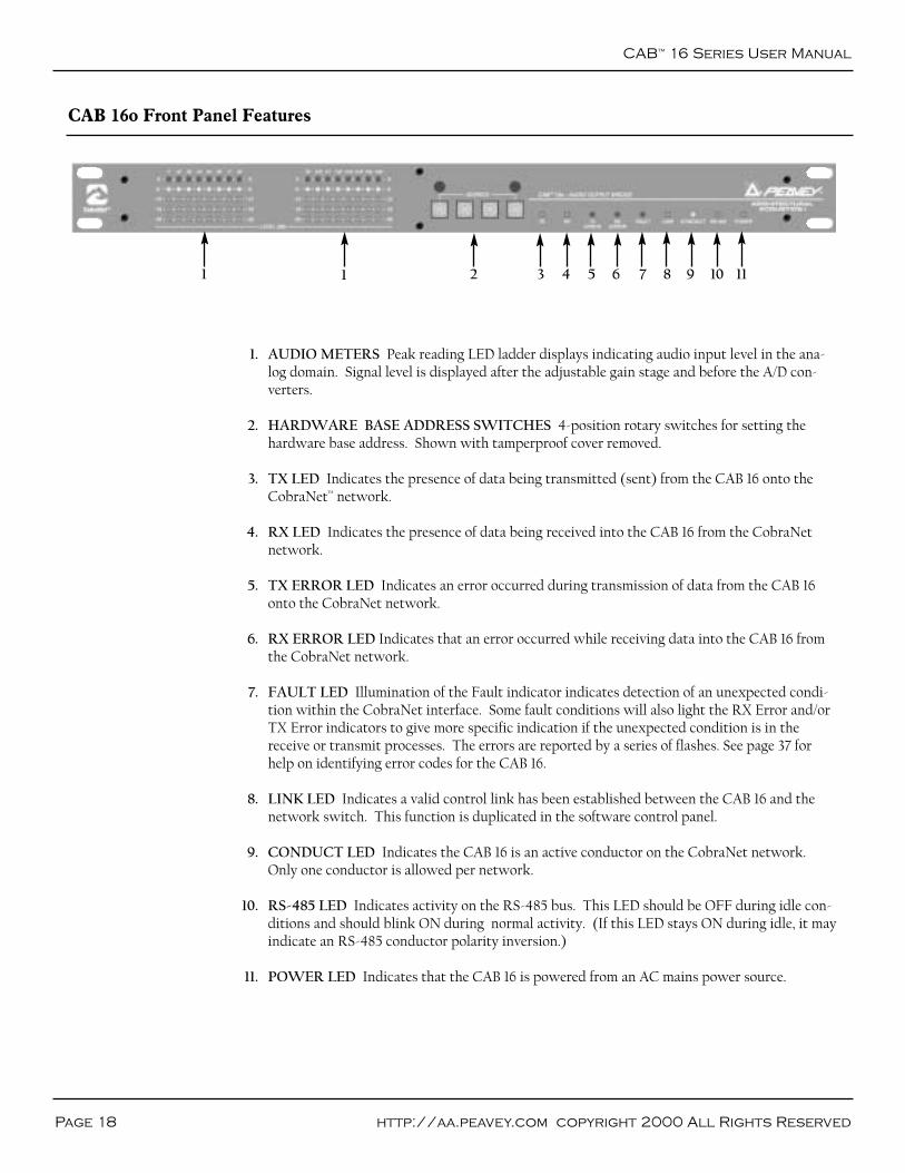
CAB 16o Front Panel Features
1 2 3 4 5 6 7 8 9 10 111
AUDIO METERS Peak reading LED ladder displays indicating audio input level in the ana-log domain. Signal level is displayed after the adjustable gain stage and before the A/D con-verters.
HARDWARE BASE ADDRESS SWITCHES 4-position rotary switches for setting thehardware base address. Shown with tamperproof cover removed.
TX LED Indicates the presence of data being transmitted (sent) from the CAB 16 onto theCobraNet™ network.
RX LED Indicates the presence of data being received into the CAB 16 from the CobraNetnetwork.
TX ERROR LED Indicates an error occurred during transmission of data from the CAB 16onto the CobraNet network.
RX ERROR LED Indicates that an error occurred while receiving data into the CAB 16 fromthe CobraNet network.
FAULT LED Illumination of the Fault indicator indicates detection of an unexpected condi-tion within the CobraNet interface. Some fault conditions will also light the RX Error and/orTX Error indicators to give more specific indication if the unexpected condition is in thereceive or transmit processes. The errors are reported by a series of flashes. See page 37 forhelp on identifying error codes for the CAB 16.
LINK LED Indicates a valid control link has been established between the CAB 16 and thenetwork switch. This function is duplicated in the software control panel.
CONDUCT LED Indicates the CAB 16 is an active conductor on the CobraNet network.Only one conductor is allowed per network.
RS-485 LED Indicates activity on the RS-485 bus. This LED should be OFF during idle con-ditions and should blink ON during normal activity. (If this LED stays ON during idle, it mayindicate an RS-485 conductor polarity inversion.)
POWER LED Indicates that the CAB 16 is powered from an AC mains power source.
1.
2.
3.
4.
5.
6.
7.
8.
9.
10.
11.
Panel Features
Page 19Peavey Electronics Corp
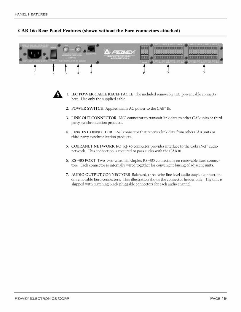
CAB 16o Rear Panel Features (shown without the Euro connectors attached)
1 2 3 4 5 6 7 7
IEC POWER CABLE RECEPTACLE The included removable IEC power cable connectshere. Use only the supplied cable.
POWER SWITCH Applies mains AC power to the CAB™ 16.
LINK OUT CONNECTOR BNC connector to transmit link data to other CAB units or thirdparty synchronization products.
LINK IN CONNECTOR BNC connector that receives link data from other CAB units orthird party synchronization products.
COBRANET NETWORK I/O RJ-45 connector provides interface to the CobraNet™ audionetwork. This connection is required to pass audio with the CAB 16.
RS-485 PORT Two two-wire, half-duplex RS-485 connections on removable Euro connec-tors. Each connector is internally wired together for convenient busing of adjacent units.
AUDIO OUTPUT CONNECTORS Balanced, three-wire line level audio output connectionson removable Euro connectors. This illustration shows the connector header only. The unit isshipped with matching black pluggable connectors for each audio channel.
1.
2.
3.
4.
5.
6.
7.

CAB™
16 Series User Manual
Page 20 http://aa.peavey.com copyright 2000 All Rights Reserved
CAB 16d Front Panel Features
2 3 4 5 6 7 8 9 10 11 121 2
METER SELECT This meter toggles in the function of the front panel audio meters betweeninput and output. The corresponding LED indicates the active meter function.
AUDIO METERS Peak reading, switchable LED ladder displays indicating audio level in thedigital domain. These meters indicate input OR output level depending on the position of thefront panel METER SELECT switch and/or the Meter Input and Meter Output switches inthe CAB 16d Software Device dialog box (p 14).
HARDWARE BASE ADDRESS SWITCHES 4-position rotary switches for setting thehardware base address. Shown with tamperproof cover removed.
TX LED Indicates the presence of data being transmitted (sent) from the CAB 16 onto theCobraNet™ network.
RX LED Indicates the presence of data being received into the CAB 16 from the CobraNetnetwork.
TX ERROR LED Indicates an error occurred during transmission of data from the CAB 16onto the CobraNet network. (See Appendix, Error Reporting.)
RX ERROR LED Indicates that an error occurred while receiving data into the CAB 16 fromthe CobraNet network. (See Appendix, Error Reporting.)
FAULT LED Illumination of the Fault indicator indicates detection of an unexpected condi-tion within the CobraNet interface. Some fault conditions will also light the RX Error and/orTX Error indicators to give more specific indication if the unexpected condition is in thereceive or transmit processes. The errors are reported by a series of flashes. See page 37 forhelp on identifying error codes for the CAB 16.
LINK LED Indicates a valid control link has been established between the CAB 16, the cableplant and the network switch. This function is duplicated in the software control panel.
CONDUCT LED Indicates the CAB 16 is an active conductor on the CobraNet network.Only one conductor is allowed per network.
RS-485 LED Indicates activity on the RS-485 bus. This LED should be OFF during idle con-ditions and should blink ON during normal activity. (If this LED stays ON during idle, it mayindicate an RS-485 conductor polarity inversion.)
POWER LED Indicates that the CAB 16 is powered from an AC mains power source.
1.
2.
3.
4.
5.
6.
7.
8.
9.
10.
11.
12.
Panel Features
Page 21Peavey Electronics Corp
CAB 16d Rear Panel Features (shown without the Euro connectors attached)
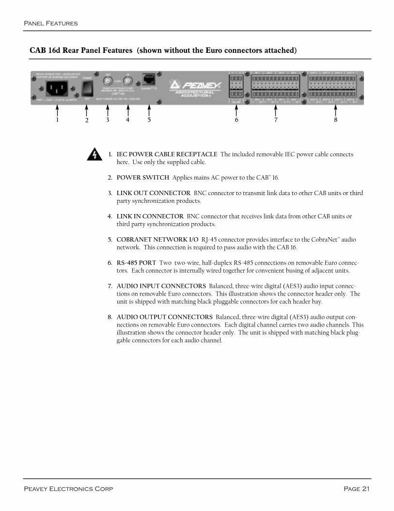
1 2 3 4 5 6 7 8
IEC POWER CABLE RECEPTACLE The included removable IEC power cable connectshere. Use only the supplied cable.
POWER SWITCH Applies mains AC power to the CAB™ 16.
LINK OUT CONNECTOR BNC connector to transmit link data to other CAB units or thirdparty synchronization products.
LINK IN CONNECTOR BNC connector that receives link data from other CAB units orthird party synchronization products.
COBRANET NETWORK I/O RJ-45 connector provides interface to the CobraNet™ audionetwork. This connection is required to pass audio with the CAB 16.
RS-485 PORT Two two-wire, half-duplex RS-485 connections on removable Euro connec-tors. Each connector is internally wired together for convenient busing of adjacent units.
AUDIO INPUT CONNECTORS Balanced, three-wire digital (AES3) audio input connec-tions on removable Euro connectors. This illustration shows the connector header only. Theunit is shipped with matching black pluggable connectors for each header bay.
AUDIO OUTPUT CONNECTORS Balanced, three-wire digital (AES3) audio output con-nections on removable Euro connectors. Each digital channel carries two audio channels. Thisillustration shows the connector header only. The unit is shipped with matching black plug-gable connectors for each audio channel.
1.
2.
3.
4.
5.
6.
7.
8.

Page 22 http://aa.peavey.com copyright 2000 All Rights Reserved
CAB™
16 Series User Manual
Basic CobraNet Network Connections
The CAB 16 Series products feature 4 different connection types. (Refer to the Rear Panel Details.) First in priority is theCobraNet™ network port. This RJ-45 connector is designed to connect with standard, off-the-shelf Category 5 (CAT 5) cablefor use with standard Ethernet network switches. This cabling interconnect is commonly referred to as the wiring “backbone”.This backbone must be properly designed for each system. Ideally, this cabling and its associated hardware would be designed,installed and certified by a competent network systems engineer.
A typical CobraNet system would include a CAT 5 cable from each CAB 16 to a network switch. An additional CAT 5 cablewould connect the switch to one or more MM-DSP-cn cards within the MediaMatrix frame. The example below is the mostbasic configuration. Large systems on managed networks can get very complex. Please don’t get ahead of yourself here! Youneed to be able to make this configuration work first!
Fig. 4, Typical Network Connections
Fig. 5, Direct Connection Example
Standard CAT5 Cable
“Crossover” CAT5 Cable(See p. 26-27)
100 Base T Network Switch
CAB 16oCAB 16i
CAB 16o
MediaMatrix Frame with MM-DSP-cn DPU Card
Alternately, you can connect the CAB 16 CobraNet port directly to the CobraNet port on your MM-DSP-cn card, bypassing theneed for a switch. However, this type of direct connection requires a "crossover" cable. (See p. 26-27 for CAT 5 cable details.) Itshould be emphasized that with this direct connection method, you cannot connect more than a single CAB product to an MM-DSP-cn card. This type of connection is normally used for testing and troubleshooting and has limited advantages in actual sys-tem installations.
MediaMatrix Frame with one MM-DSP-cn DPU Card

Audio & RS-485 Connections
Page 23Peavey Electronics Corp
Audio Connections
The second connection is audio. Each audio connection on the CAB™ 16i and 16o is a single three-wire, balanced analog circuit.The connections on both of these units is identical, except one is an input, the other an output. The method is the same. Forthe CAB 16d however, the method is slightly different. Each three wire connection on the 16d is a balanced, two-channel digital(AES3 or S/PDIF, see p. 24-25) connection. AES3 compliant cable should be used with all connections on the 16d. As with anyelectronic connection, care should be taken to ensure that the termination is solid. There should be no stray wire strands,kinks or nicks in the wire jacket for a proper termination. And as always, audio connections should be made with high qualityshielded wire.
Fig. 6, Analog and Digital Audio Connections
Analog (16i)Balanced Input
Positive (+)Negative (-)Shield (SH)
Standard audio cable
Balanced ConnectionPositive (+)Negative (-)Shield (SH)
Analog (16o)Balanced Output
Positive (+)Negative (-)Shield (SH)
Standard audio cable
From RS-485 Device To Next RS-485 Device
Plug this.....
...here
RS-485 Connections
The third connection is the CAB Series RS-485 Serial Port. All CAB Series products include this powerful feature that enablesyou to “bridge” serial data between CAB locations on the CobraNet™ network. You can think of this as a kind of “sub-network”that travels across the CobraNet infrastructure independently of the audio data. This feature has many uses, but is primarilyused to transport control data for the optional AmpWare amplifier control and monitoring software. In this case, the connec-tion would terminate directly to an IA™ Series power amplifier equipped with an ACI™-485V interface module. The data formatis Half-Duplex, two-wire, balanced. Again, care should be taken to insure that your termination is correctly installed and highquality shielded wire should be used.
Fig. 7, RS-485 Serial Data Connections
NOTE: The RS-485 connector hastwo sets of terminations that arewired in parallel. This allows you to“bus” adjacent serial data connec-tions at each network location.With this type of connection, thereis no “input” or “output”.
Digital (16d)Two Channel Conn.
Positive (+)Negative (-)Shield (SH)
AES3 / 110 Ohm cable

CAB™
16 Series User Manual
Page 24 http://aa.peavey.com copyright 2000 All Rights Reserved
Using S/PDIF
with the CAB 16d
Wire & Cable
The CAB 16d has been designed for use with AES3 (AES/EBU) and S/PDIF(Sony/Philips Digital Interface Format) digital audio signals. The CAB 16d isshipped from the factory to accommodate AES3 digital audio right out of thebox. You can connect AES sources directly to the CAB 16d’s input and out-put terminals without any regard to additional interface boxes or converters.
When using S/PDIF digital audio signals however, it is recommended thatthe following interface circuits be used between the S/PDIF audio device andthe CAB 16d. There are differences in the voltage levels, load and cableimpedance between AES3 and S/PDIF formats. Using these “matching inter-faces” will ensure seamless operation of S/PDIF digital audio by minimizingsignal reflections and providing correct signal levels for S/PDIF operation.
The following illustrations show S/PDIF terminations to the CAB 16d’s inputand output connectors. The S/PDIF connections are illustrated as unbal-anced consumer RCA connectors, which is typically the standard connectorfor copper based S/PDIF wiring. There is also an optical version of theS/PDIF standard which uses a fiber cable that is not a part of this discussion.
It is important to know that the audio data is the same in both AES3 andS/PDIF formats, but because of the differences in their subcode, they areactually different formats. Just making a wire conversion is not enough.AES3 on an XLR connector converted to an unbalanced RCA connector isNOT S/PDIF, and vice versa. The native formats are still the same, only thetransport media has changed. To make sure that your S/PDIF audio signalswork correctly with the CAB 16d, it is required that these circuits beinstalled between the S/PDIF devices and the CAB 16d.
An important fact of digital audio transport is that the wire type is signifi-cantly different than wire used for terminating analog audio circuits. AES3uses symmetrical connections with transformer isolation and an outputimpedance of 110 Ohms. The signal-level of this interface is higher than inthe consumer S/PDIF version. Because AES3 digital audio signals are trans-mitted at high, video-like frequencies, they should be handled very different-ly than standard analog audio lines. Failure to use the proper wire and cablecan cause poor digital transmission performance resulting in signal dropout.With proper termination, AES3 signal transmission lines can easily exceedseveral thousand feet when using high quality, certified cable.
S/PDIF however, uses 75 Ohm coaxial cable. Because it is the same type ofcable used in common consumer video circuits, this type of wire is inexpen-sive and readily available. You can even buy pre-made S/PDIF cables at mostretail outlets that sell consumer electronics products. By specification, themaximum length of a properly terminated S/PDIF cable is 25 feet. If highquality 75 Ohm cable with premium gold 75 Ohm RCA connectors are used,it is possible to get good results with much longer lines. The actual lengthsare unknown however, since it depends on the quality of the transmittingcircuit, the receiving circuit and the impedance match for the entire line,including the connectors. In general, coaxial S/PDIF connections work bestin the 8-10 meter range with good 75 Ohm coaxial cable. We do not recom-mend that you exceed this distance when using S/PDIF devices with theCAB 16d.

S/PDIF Connections
Page 25Peavey Electronics Corp
To drive an S/PDIF input from the CAB 16d’s out-put, a similar circuit must be implemented. Again,the impedance of the CAB 16d must be matched toproperly terminate to the S/PDIF input. This isaccomplished by using a 22 Ohm resistor across theoutput of the CAB 16d. The level correction isaccomplished by placing a 75 Ohm and a 56 Ohmresistor in series with the positive side of the CAB16d’s output as shown. The negative side is carriedstraight through to the shield conductor of theS/PDIF device’s input. (Jumper is optional.)
In addition to adding the resistor circuits, it may also be necessary to configure the CAB 16d outputCHANNEL STATUS to Consumer Mode before the interface between the S/PDIF device and CAB 16d is completed.The Consumer Mode Select Switch can be found in the CAB 16d CHANNEL STATUS BLOCK, located within theCAB 16d’s software control panel. (See pages 14-15.)
Connecting an S/PDIF Source to a CAB 16d inputrequires that the output level and impedance of theS/PDIF source be matched to the CAB 16d’s inputcircuit. The following circuit provides attenuationfrom the source through one in-line 51 Ohm resistoron the positive leg of the signal. The impedancematching is accomplished by using a 150 Ohm resis-tor across both legs of the S/PDIF source signal.NOTE: A jumper is required between the negativeand SH terminals to complete the termination.
When making these interface connections, it is important to install the resistors at the CAB™ 16d’s output terminal, using theremovable Euro connector. The design of this connector, supplied with the CAB 16d, will provide a solid mechanical mount forthe resistors. The wiring from the consumer RCA coax cable should be soldered to the other side of the resistor network. Allinterconnecting joints should be soldered as well. All resistors should be 1% or 5% tolerance, 5 W, typical.
RCA connector
To S/PDIF inputFrom S/PDIF output
Unbalanced Coax
Positive “Hot” wire
Negative/Shield 22 Ohm resistor
56 Ohm resistor
75 Ohm resistor
51 Ohm resistor
Jumper
150 Ohm resistor
Fig. 8, S/PDIF resistor network configurations
CAB™
16 Series User Manual
Page 26 http://aa.peavey.com copyright 2000 All Rights Reserved
CAT 5 cable is your friend....
Well, you’ve been in the audio business for a while now....you know all about audio connections, balanced cables, multi-pairs,SJO, TRS this and XLR that....you can dress off a wiring harness like nobody’s business....then, the industry throws “CAT 5” atyou....! So, what exactly is Category 5 cabling, and how do I terminate it?
Category 5 cable, or “CAT 5” as it is commonly known, is a wiring standard that became popular when computer networksmoved from a “bus” topology to a “star” or...... “every box is a home run” topology. The wire itself consists of 8 conductors, iden-tified into 4 pairs, and although only two of these pairs are actually used, all four are terminated. It is a UTP (UnshieldedTwisted Pair) configuration, in true telco, or AT&T style. The cable is coupled to in-line RJ-45 connectors, also a Bell/AT&Tstandard. Special crimping tools are required to make the termination, and are available everywhere, as are the connectors.Oh...and before you start designing cable plants for small cities....a single CAT 5 cable run should not exceed 100 meters.
Just like telco wire, there are stranded and solid varieties of CAT 5 cable. This is important to know, because the RJ-45 connec-tor is different for each type of wire. The standard “bent tyne” style connector is intended for use with solid core wire, and the“aligned tyne” connector is for use with standard wire. There have been errors when using incorrect cable/connector combina-tions, so be careful. The "bent tyne" connector will generally work on stranded wire by the way, but not the other way around.In general, make sure your connector matches your cable type. If you aren’t sure, use the “bent tyne” variety.
When terminating CAT 5 cable, it is important that the natural twist of each pair be carried through as close as possible to thepoint of termination at the connector. The EIA standard requires no more than 1/2 inch be left untwisted. More than 1/2 inchof untwisted cable will affect performance at high bit rates. Although only 2 of the 4 twisted pairs are used for Ethernet, it isimportant that all pairs be terminated, and that the conductors be twisted together in pairs.
The illustrations should give you the basics for getting your cables, and your audio system up and running. Although pre-made,molded style cables are preferred, they are usually impractical, since your cabling route, distance and locations are based on thejobsite conditions and not your test bench. Additionally, you will need rack wiring, and bulk cable is the preferred way to dressoff a wire harness, as we all know. Since this manual is printed in grayscale, you will not be able to see the color code of thewire. We have labeled them for your convenience, but you should get familiar with the color schemes so they are second natureto you. An error in the cabling of your audio network is often the primary cause of system errors, so....take your time, learn itthoroughly and DO IT RIGHT THE FIRST TIME!
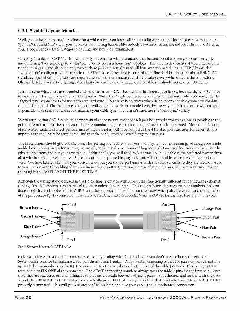
Although the wiring standard used in CAT 5 cabling originates with AT&T, it is functionally different for configuring ethernetcabling. The Bell System uses a series of colors to indentify wire pairs. This color scheme identifies the pair numbers, and con-ductor polarity, and applies to the WIRE....not the connector. It is important to know what pairs are which, and the functionof the pins on the RJ-45 connector. The colors are BLUE, ORANGE, GREEN and BROWN for the first four pairs. The color
code extends well beyond that, but since we are only dealing with 4 pairs of wire, you don’t need to know the entire BellSystem color code for terminating a 900 pair distribution trunk...! What is often confusing is that the pair numbers do not lineup with the pin numbers on the RJ-45 connector. In other words, conductor ONE of the cable (White w/Blue Strip) is NOTterminated to PIN ONE of the connector. The AT&T connecting standard always uses the middle pins for the first pair. Afterthat, they are staggered around, primarily to prevent crosstalk between adjacent pairs. For ethernet, and for use with the CAB16, only the ORANGE and GREEN pairs are actually used. BUT...it is very important that you build the cable with ALL PAIRSproperly terminated. This will prevent any confustion later, and give your cable a solid mechanical connection.
Fig. 9, Standard “normal” CAT 5 cable
Blue Pair
Orange Pair
Green Pair
Brown Pair
Pin 1 Pin 8
Pin 8 Pin 1
Blue Pair
Brown Pair
Green Pair
Orange Pair

CAT 5 Cables
Page 27Peavey Electronics Corp
Crossover cables are used to connect switches to other switches or CAB 16s directly to the DPU card. Also, a crossover cable iswhat you would use if you were to connect a CAB 16 to another CAB 16, for use as a digital “snake”. A crossover cable is termi-nated the same way as a normal cable, except that the TX and RX pins are "swapped" at one end to allow the transmit pair ofone device to connect to the receive pair of the other. Normally, this crossover action is done within the switch, which is whyyou use a straight-through cable most of the time.
It is very easy to tell the difference between a crossover cable and a straight-through cable by looking at the conductors in theRJ-45 connectors. If the wiring is identical at both ends, you are looking at a straight-through cable. If it is different, you mostlikely have a crossover cable, or possibly, an incorrectly terminated cable. Look carefully at the color of the conductors.
It is important to note that some switches include “uplink” ports. These ports are intended to serve as a connection to anotherswitch. As such, the uplink port is wired to use a straight-through cable instead of requiring a crossover cable. On some switch-es, uplink ports share their connection with an adjacent port, so be sure to read the manufacturer's instructions for proper use.
White w/blue stripe
Blue w/white stripe
White w/orange stripe
Orange w/white stripe
White w/green stripe
Green w/white stripe
White w/brown stripe
Brown w/white stripe
Conductor
1
1
2
2
3
3
4
4
Wire Pair
5
4
1 (3 x-over)
2 (6 x-over)
3 (1 x-over)
6 (2 x-over)
7
8
Connector Pin
Not used
Not used
TX +
TX -
RX +
RX -
Not used
Not used
Function
TX Pair
Pins (1-8)
RX PairRemember, for ethernet, the BLUE and BROWN pairs are not used. TheORANGE pair is transmit (TX), and the GREEN pair is receive (RX). Thereis a positive and negative conductor for each pair, indicated by the color code.Notice on the chart that the order of the wire pairs does not follow the con-nector pins, as mentioned earlier. Don’t let that confuse you. The first wire ofa given pair is always the white wire with a colored stripe and is the positiveconductor. The corresponding colored wire with the white stripe is the nega-tive conductor for that pair.
Crossover Cables
Normal CAT 5 cables are designed to connect the CAB™ 16 to a networkswitch only. You cannot use this type of cable to connect a CAB 16 directly toa MediaMatrix MM-DSP-cn DPU card. For that you need a “crossover” cable.The pin assignments for a crossover cable, shown in parentheses on the chart,apply to ONE END of the cable ONLY!
+-
Conductors
RJ-45 Shell
Jacketed Cable
+-
Fig. 12, CAT 5 “crossover” cable
Fig. 11, CAT 5 cable and RJ-45 termination detailsFig. 10, CAT 5 Wire/Connector cross reference chart, standard & crossover cable types.
Blue Pair
Brown Pair
Orange Pair
Green Pair
Blue Pair
Orange Pair
Green Pair
Brown Pair
Pin 1
Pin 8
Pin 8
Pin 1

CAB™
16 Series User Manual
Page 28 http://aa.peavey.com copyright 2000 All Rights Reserved
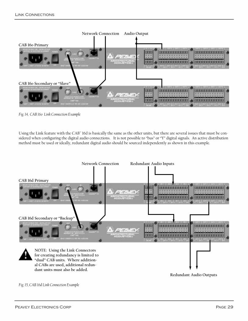
Link Connections
All CAB Series products feature built-in “Buddy Link” func-tionality for creating backup I/O configurations in missioncritical systems. The term “Buddy Link” extends to multipledimensions within MediaMatrix, but in this context, we areconcerned only with how the built-in Buddy Link works withthe CAB 16 Series products. For more detailed information onhow Buddy Link works with MediaMatrix and/or CobraNet™,please refer to our website, or to the resource list at the end ofthis manual.
Each CAB 16 Series product features rear panel, dual BNCconnectors labeled LINK IN and LINK OUT. These connec-tors enable you to connect adjacent, CAB units for redundan-cy and define the role of dual units. In this configuration, oneCAB is declared the primary and transmits data via its LINKOUT connector. The other CAB is the secondary, or backup,and receives data at its LINK IN connector. A high quality,broadcast grade video cable, RG-59 with male BNC connec-tors on each end is used to make the connection between theprimary and secondary CABs. A single cable is used for dualCABs in this redundant configuration. The connection isalways LINK OUT (Primary) to LINK IN (Slave).
Audio input (CAB 16i) or output (CAB 16o) signals shouldappear at both units, in parallel, so if one fails, the redundantunit will have the same connection. By nature of the BuddyLink functionality, the secondary unit is always “off-line”until needed and therefore the paralleling of the audio connec-tions is of no consequence. (Exception 16d, see next page.)
For this feature to work properly, both units must be config-ured to use the same Audio Bundle number (p. 30-31). Aslong as the primary unit is powered on, and it sees a good
CobraNet connection (Ethernet link status good), and it hasnot experienced a fault, it generates a signal from its LINKOUT connector which inhibits the secondary unit from tak-ing over until there is a failure or fault.
The action of the switch-over is different for the CAB 16i andthe CAB 16o. In the case of the CAB 16i, input audio is pres-ent simultaneously at both units and both units will passaudio internally. You can see this by the duplication of audiopresence on the front panel meters. To prevent confusionfrom duplicated audio signals in the system, the secondaryCAB 16i is prevented from transmitting onto the CobraNetnetwork by the action of the Buddy Link. Therefore, only oneset of audio inputs is present within the system at a time.
In the case of the CAB 16o, both units are simultaneouslyactive on the network, but the secondary unit’s audio outputis muted. This prevents an audio “collision” of duplicate audiooutput signals at the amplifiers.
The Buddy Link feature also monitors the integrity of theLINK CABLE. When using dual CAB 16is, a cable failure willcause the secondary unit to take over transmission onto theCobraNet network. When using CAB 16os, both units will beactive, and will simultaneously generate analog audio output,resulting in gain and possible spectral distortion in the result-ing combined signal.
The Buddy Link functionality can also be placed under soft-ware control and is used in systems where remote access tothe link is required. (See the resource list at the end of thismanual for additional information on this topic.)
Fig. 13, CAB 16i Link Connection Example
CAB 16i Primary
Audio InputNetwork Connection
CAB 16i Secondary or “Backup”
Link Connections
Page 29Peavey Electronics Corp
Fig. 15, CAB 16d Link Connection Example
Using the Link feature with the CAB™ 16d is basically the same as the other units, but there are several issues that must be con-sidered when configuring the digital audio connections. It is not possible to “bus” or “Y” digital signals. An active distributionmethod must be used or ideally, redundant digital audio should be sourced independently as shown in this example.
NOTE: Using the Link Connectorsfor creating redundancy is limited to“dual” CAB units. Where addition-al CABs are used, additional redun-dant units must also be added.
CAB 16o Primary
CAB 16o Secondary or “Slave”
Audio Output
CAB 16d Primary
Redundant Audio Inputs
CAB 16d Secondary or “Backup”
Redundant Audio Outputs
Network Connection
Network Connection
Fig. 14, CAB 16o Link Connection Example

CAB™
16 Series User Manual
Page 30 http://aa.peavey.com copyright 2000 All Rights Reserved
Setting the Hardware Base Address
Once you have a valid physical connection to the network port, you now must configure the port on both ends of the networkmedia to establish communications between the MediaMatrix software and the CAB 16. This is a critical configuration sinceyou will not be able to pass audio or enable communications without it. Please keep in mind that there are two separate set-tings for successful communications on the CobraNet™ network. One is the Hardware Base Address, the other is the “Bundle”which will be discussed in a separate section. First things first.....
The first step is to set your Hardware Base Address. Correctly settingthis ID will enable communications between the CAB 16 and its associ-ated control panel, the “Taxi” device within MediaMatrix. On the frontpanel of the CAB 16, there is a hardware base address switch. Thisswitch, which is actually 4 small rotary switches, is hidden behind asmall metal panel. This panel is held in place by two thumb screws.Remove these screws to gain access to the hardware base addressswitches. Refer to Fig. 16, Hardware Base Address Switches.
A Hardware Base Address has 4 digits. Acceptable values are in hexand range from 0001 to 7FFF. From left to right, the four rotary switch-es represent your 4 digit Hardware Base Address number. If you look
carefully, there is a small arrow on each switch indicating the selected number. Using a small Phillips screwdriver, carefully seteach rotary switch to the desired number. You will feel a “click” as you move between digits. Be careful, and do not force theswitch.
The next step is to set the same address within the MediaMatrix software using the yellow CAB device, or as I mentioned earli-er, the “Taxi”. The Taxi device represents the actual hardware, and there must be one Taxi for each physical CAB 16. In addi-tion to this hardware address setting, the Taxi device includes the CAB 16’s analog controls and the CobraNet “Bundle” assign-ment control for the CAB 16’s audio network channel. More on that later.
Now, let's set up the hardware address within the software and establish communications between the MediaMatrix and theCAB 16. Refer to Fig. 17, “Hardware & Software Addressing Controls”.
(Ensure that you have the simple view shown in the section on page 11 constructedand compiled for these steps. Refer to the MediaMatrix Help file for details onMediaMatrix basics.)
Find the yellow box labeled CAB 16i or 16o.....the “Taxi”. Open the device by double-clicking on it. In the upper right hand corner of this box is the Hardware BaseAddress ID Control. This control has a 4-digit ID number which corresponds tothe 4-digit Address ID on the actual CAB hardware. While in CCoonnttrroollMMooddee, set the Hardware Base Address to match (exactly) the 4-digitaddress you set on the physical CAB 16 unit earlier. To do this, clickonce (in CCoonnttrrooll MMooddee) on the address box and type your hex basedalpha-numeric ID number. When a valid number is entered, the greenID LED next to the ID number should light, indicating that the IDnumber you entered is valid.
Now you are ready to test your connection. If you have done everythingcorrectly, you should now have communications between theMediaMatrix frame and the CAB 16. If so, the front panel TX and RXLED’s will indicate traffic. You can further test the connection by test-ing the functions of the CAB and verifying the response.
Fig. 16, Hardware Base Address Switches
Fig. 17, Hardware & Software Addressing Controls
Configuration
Page 31Peavey Electronics Corp
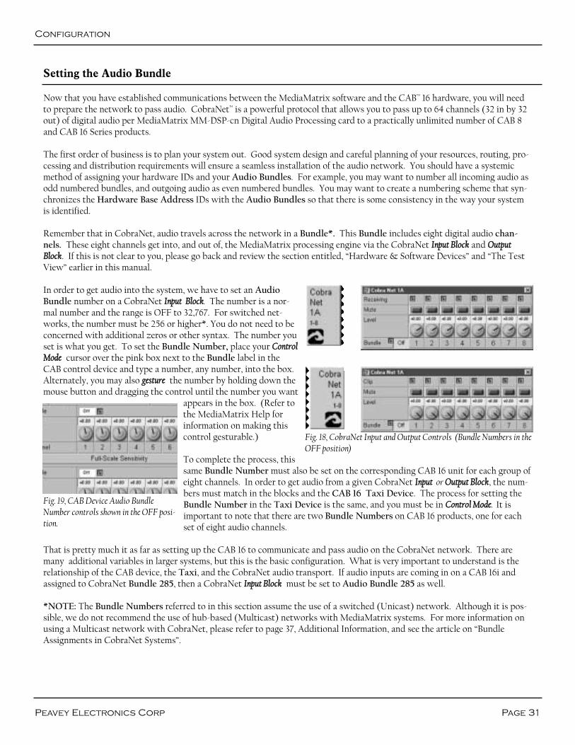
Setting the Audio Bundle
Now that you have established communications between the MediaMatrix software and the CAB™ 16 hardware, you will needto prepare the network to pass audio. CobraNet™ is a powerful protocol that allows you to pass up to 64 channels (32 in by 32out) of digital audio per MediaMatrix MM-DSP-cn Digital Audio Processing card to a practically unlimited number of CAB 8and CAB 16 Series products.
The first order of business is to plan your system out. Good system design and careful planning of your resources, routing, pro-cessing and distribution requirements will ensure a seamless installation of the audio network. You should have a systemicmethod of assigning your hardware IDs and your Audio Bundles. For example, you may want to number all incoming audio asodd numbered bundles, and outgoing audio as even numbered bundles. You may want to create a numbering scheme that syn-chronizes the Hardware Base Address IDs with the Audio Bundles so that there is some consistency in the way your systemis identified.
Remember that in CobraNet, audio travels across the network in a Bundle*. This Bundle includes eight digital audio chan-nels. These eight channels get into, and out of, the MediaMatrix processing engine via the CobraNet IInnppuutt BBlloocckk and OOuuttppuuttBBlloocckk. If this is not clear to you, please go back and review the section entitled, “Hardware & Software Devices” and “The TestView” earlier in this manual.
In order to get audio into the system, we have to set an AudioBundle number on a CobraNet IInnppuutt BBlloocckk. The number is a nor-mal number and the range is OFF to 32,767. For switched net-works, the number must be 256 or higher*. You do not need to beconcerned with additional zeros or other syntax. The number youset is what you get. To set the Bundle Number, place your CCoonnttrroollMMooddee cursor over the pink box next to the Bundle label in theCAB control device and type a number, any number, into the box.Alternately, you may also ggeessttuurree the number by holding down themouse button and dragging the control until the number you want
appears in the box. (Refer tothe MediaMatrix Help forinformation on making thiscontrol gesturable.)
To complete the process, thissame Bundle Number must also be set on the corresponding CAB 16 unit for each group ofeight channels. In order to get audio from a given CobraNet IInnppuutt or OOuuttppuutt BBlloocckk, the num-bers must match in the blocks and the CAB 16 Taxi Device. The process for setting theBundle Number in the Taxi Device is the same, and you must be in CCoonnttrrooll MMooddee. It isimportant to note that there are two Bundle Numbers on CAB 16 products, one for eachset of eight audio channels.
That is pretty much it as far as setting up the CAB 16 to communicate and pass audio on the CobraNet network. There aremany additional variables in larger systems, but this is the basic configuration. What is very important to understand is therelationship of the CAB device, the Taxi, and the CobraNet audio transport. If audio inputs are coming in on a CAB 16i andassigned to CobraNet Bundle 285, then a CobraNet IInnppuutt BBlloocckk must be set to Audio Bundle 285 as well.
*NOTE: The Bundle Numbers referred to in this section assume the use of a switched (Unicast) network. Although it is pos-sible, we do not recommend the use of hub-based (Multicast) networks with MediaMatrix systems. For more information onusing a Multicast network with CobraNet, please refer to page 37, Additional Information, and see the article on “BundleAssignments in CobraNet Systems”.
Fig. 18, CobraNet Input and Output Controls (Bundle Numbers in theOFF position)
Fig. 19, CAB Device Audio BundleNumber controls shown in the OFF posi-tion.

CAB™
16 Series User Manual
Page 32 http://aa.peavey.com copyright 2000 All Rights Reserved
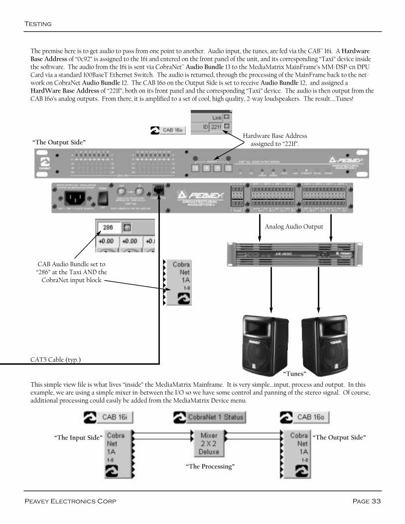
Testing, Testing.....
At this point, it is a good idea to see if everything is working. The example below is a good way to test your system and seehow everything relates. Hook up some tunes, an amp and a speaker and see if you hear anything. The audio should be cleanand clear. Listen for dropouts, distortion and other undesirable noises. If you hear any of this, especially dropouts, you've got aproblem. Also, take note of the action of the front panel status LEDs. There should be lots of green, and no red.
Hardware Base Addressassigned to “0c92”.
CAB™ Audio Bundle set to“285” at the Taxi AND the
CobraNet™ input block
“The Input Side, a CAB 16i”
“The Tunes”
“The Processing, aMediaMatrix System”
MediaMatrixMainFrame (shownwith 1-MM-DSP-cn
and 1-MM-DSPcards)
Analog Audio Input
100 BaseT Ethernet Switch
CobraNetNetwork
Connector (MM-DSP-cn)
Testing
Page 33Peavey Electronics Corp
The premise here is to get audio to pass from one point to another. Audio input, the tunes, are fed via the CAB™ 16i. A HardwareBase Address of “0c92” is assigned to the 16i and entered on the front panel of the unit, and its corresponding “Taxi” device insidethe software. The audio from the 16i is sent via CobraNet™ Audio Bundle 13 to the MediaMatrix MainFrame’s MM-DSP-cn DPUCard via a standard 100BaseT Ethernet Switch. The audio is returned, through the processing of the MainFrame back to the net-work on CobraNet Audio Bundle 12. The CAB 16o on the Output Side is set to receive Audio Bundle 12, and assigned aHardWare Base Address of “221f”, both on its front panel and the corresponding “Taxi” device. The audio is then output from theCAB 16o’s analog outputs. From there, it is amplified to a set of cool, high quality, 2-way loudspeakers. The result....Tunes!
This simple view file is what lives “inside” the MediaMatrix Mainframe. It is very simple...input, process and output. In thisexample, we are using a simple mixer in-between the I/O so we have some control and panning of the stereo signal. Of course,additional processing could easily be added from the MediaMatrix Device menu.
“The Output Side”Hardware Base Address
assigned to “221f”.
CAB Audio Bundle set to“286” at the Taxi AND the
CobraNet input block
Analog Audio Output
CAT5 Cable (typ.)
“Tunes”
“The Output Side”“The Input Side”
“The Processing”
CAB Audio Bundle set to“285” at the Taxi AND the
CobraNet™ input block
CAB™
16 Series User Manual
Page 34 http://aa.peavey.com copyright 2000 All Rights Reserved
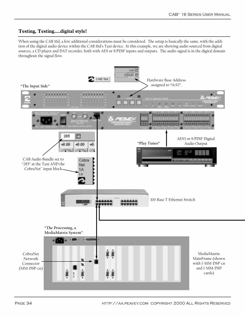
Testing, Testing.....digital style!
When using the CAB 16d, a few additional considerations must be considered. The setup is basically the same, with the addi-tion of the digital audio device within the CAB 16d’s Taxi device. In this example, we are showing audio sourced from digitalsources, a CD player and DAT recorder, both with AES or S/PDIF inputs and outputs. The audio signal is in the digital domainthroughout the signal flow.
Hardware Base Addressassigned to “0c92”.“The Input Side”
“Play Tunes”
MediaMatrixMainFrame (shownwith 1-MM-DSP-cn
and 1-MM-DSPcards)
AES3 or S/PDIF DigitalAudio Output
100 Base T Ethernet Switch
CobraNetNetwork
Connector (MM-DSP-cn)
“The Processing, aMediaMatrix System”

CAB™ Audio Bundle set to“286” at the Taxi AND the
CobraNet™ input block
AES3 or S/PDIFDigital Audio
Input
Testing
Page 35Peavey Electronics Corp
“The Output Side”
Hardware Base Addressassigned to “221f”.
CAT5 Cable (typ.)
“Record Tunes”
“The Output Side”“The Input Side”
“The Processing”

CAB™
16 Series User Manual
Page 36 http://aa.peavey.com copyright 2000 All Rights Reserved
Technical Support
Warranty Registration
Peavey has an extensive Technical Services Group that provides tech sup-port, repair and implementation services. If you require assistance with yournew CAB 16, you can get help from several sources. There are many techni-cal documents, white papers and application notes on our website and PeakAudio’s website. (See the Additional Resources section on the next page fordetails.) There are also brochures, data sheets and our newsletter, “AudioInteractive”, published monthly. Also on our website are message boardforums that include questions and answers on all audio topics. This forum isa great way to learn more about audio, Peavey products and system designfrom other audio professionals around the world. You can also get help bysending us an e-mail or posting a request on the message board. Finally, ifyou still cannot get the information you need, don’t hesitate to call us. Wehave extensive phone support services and will be happy to assist you. Thecontact information for the Architectural Acoustics Division is shownbelow:
Peavey Electronics Corp.Architectural Acoustics Division711 “A” St.Meridian, MS 39301USA
Phone: 601-483-5376Fax: 601-486-1678
Website: http://aa.peavey.com
Please take a few minutes and fill out the warranty registration card foryour CAB 16. Although your warranty is valid without the registration, theinformation you provide with the form is crucial to our support group. Itenables us to provide better service and customer support, and to keep youinformed of new product updates. Refer to the warranty statement in therear of this manual for details about what your warranty includes and whatthe limitations are.
Resources
Page 37Peavey Electronics Corp
Additional Resources
Tech Notes and General Audio:http://aa.peavey.com/tech_notes.html
MediaMatrix product line:http://aa.peavey.com/mediamatrix.html
CobraNet™ products:http://aa.peavey.com/cobranet.html
MediaMatrix Mainframe Series:http://aa.peavey.com/mainframe.html
MediaMatrix Miniframe Series:http://aa.peavey.com/miniframe.html
MediaMatrix X-Frame Series:http://aa.peavey.com/mmxframe.html
MediaMatrix Break-out Boxes:http://aa.peavey.com/bobs.html
MediaMatrix DPU cards:http://aa.peavey.com/dpucards.html
“How MediaMatrix Works”:http://aa.peavey.com/how.html
MediaMatrix product comparisons:http://aa.peavey.com/configuration.html
Redundant Operation Support When Using CobraNetMediaMatrix Help File (software download):http://aa.peavey.com/mmsoftware32.html
White Paper: Digital Audio Distribution SystemsKevin Gross, Peak Audio Inc.:http://peakaudio.com/cobranet/papers/digital_audio_dis-tribution.htm
Common CobraNet Problems & Solutions:
http://peakaudio.com/cobranet/problems.htm
Network Cabling, A Primer:http://peakaudio.com/cobranet/network_cabling.htm
Bundle Assignments in CobraNet SystemsRay Rayburn, Peak Audio Inc.:http://peakaudio.com/cobranet/papers/bundle_assign-ments.htm
CobraNet and MediaConverters:http://peakaudio.com/cobranet/papers/media_converters.htm
Error Reporting in CobraNet Systems:http://peakaudio.com/cobranet/developer/errors.htm
CobraNet Repeater Network Examples:http://peakaudio.com/cobranet/repeater.htm#diameter
CobraNet TechnologyRichard Zweibel & Kevin Gross:http://peakaudio.com/cobranet/papers/technology.htm
Digital Synchronization in CobraNet Systems:http://peakaudio.com/cobranet/papers/sync.html
Switched Network Design & Configuration:http://peakaudio.com/cobranet/examples.htmhttp://peakaudio.com/cobranet/examples.htm
CobraNet on Switched Networks:http://peakaudio.com/cobranet/switched.htm
Cobra Net Frequently Asked Questions (FAQ):http://peakaudio.com/cobranet/faq.htm
Glossary Of Terms:http://www.peakaudio.com/cobranet/terminology.htm
The use of the CAB™ 16 Series products, as well as MediaMatrix and networking technology require a thorough understandingof several advanced topics. It is highly recommended that the designer acquire an understanding of these topics so that theprocess of systems work is efficient and cost-effective.
There are several excellent sources for obtaining information regarding these topics. The resource list below represents themost current documentation on the state-of-the-art as of the date of this printing (Fall 2000). The links are a part of the PeaveyArchitectural Acoustics or Peak Audio websites. Additional information not listed below is also available. As in any high tech-nology environment, this information is constantly under a state of flux. It is important to know what you are reading, the vin-tage of your hardware and software and the application for which it is intended. Good documentation will almost alwaysensure this, provided that it is read, comprehended and retained. We sincerely hope that you enjoy your new CAB Series prod-uct and that you learn a lot in the process. Enjoy!
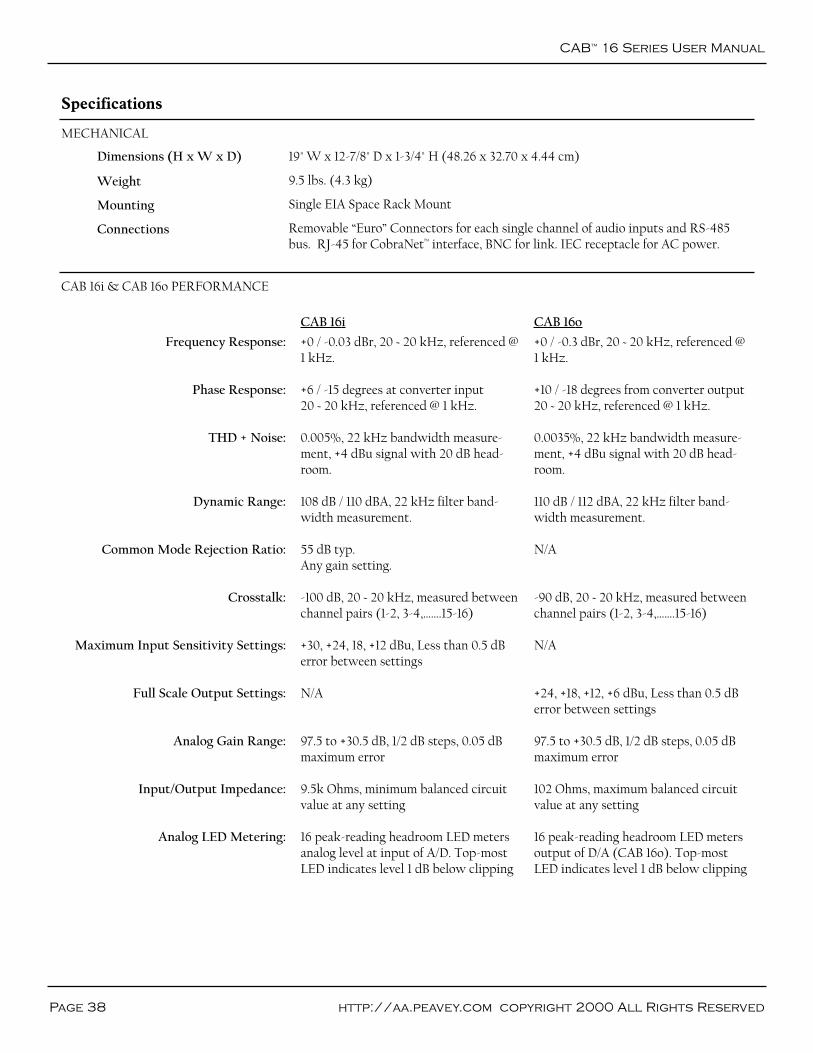
CAB™
16 Series User Manual
Page 38 http://aa.peavey.com copyright 2000 All Rights Reserved
Specifications
MECHANICAL
CAB 16i & CAB 16o PERFORMANCE
CAB 16i CAB 16o
Dimensions (H x W x D)
Weight
Mounting
Connections
19" W x 12-7/8" D x 1-3/4" H (48.26 x 32.70 x 4.44 cm)
9.5 lbs. (4.3 kg)
Single EIA Space Rack Mount
Removable “Euro” Connectors for each single channel of audio inputs and RS-485bus. RJ-45 for CobraNet™ interface, BNC for link. IEC receptacle for AC power.
Frequency Response:
Phase Response:
THD + Noise:
Dynamic Range:
Common Mode Rejection Ratio:
Crosstalk:
Maximum Input Sensitivity Settings:
Full Scale Output Settings:
Analog Gain Range:
Input/Output Impedance:
Analog LED Metering:
+0 / -0.03 dBr, 20 ~ 20 kHz, referenced @1 kHz.
+6 / -15 degrees at converter input20 ~ 20 kHz, referenced @ 1 kHz.
0.005%, 22 kHz bandwidth measure-ment, +4 dBu signal with 20 dB head-room.
108 dB / 110 dBA, 22 kHz filter band-width measurement.
55 dB typ.Any gain setting.
-100 dB, 20 ~ 20 kHz, measured betweenchannel pairs (1-2, 3-4,…….15-16)
+30, +24, 18, +12 dBu, Less than 0.5 dBerror between settings
N/A
97.5 to +30.5 dB, 1/2 dB steps, 0.05 dBmaximum error
9.5k Ohms, minimum balanced circuitvalue at any setting
16 peak-reading headroom LED metersanalog level at input of A/D. Top-mostLED indicates level 1 dB below clipping
+0 / -0.3 dBr, 20 ~ 20 kHz, referenced @ 1 kHz.
+10 / -18 degrees from converter output20 ~ 20 kHz, referenced @ 1 kHz.
0.0035%, 22 kHz bandwidth measure-ment, +4 dBu signal with 20 dB head-room.
110 dB / 112 dBA, 22 kHz filter band-width measurement.
N/A
-90 dB, 20 ~ 20 kHz, measured betweenchannel pairs (1-2, 3-4,…….15-16)
N/A
+24, +18, +12, +6 dBu, Less than 0.5 dBerror between settings
97.5 to +30.5 dB, 1/2 dB steps, 0.05 dBmaximum error
102 Ohms, maximum balanced circuitvalue at any setting
16 peak-reading headroom LED metersoutput of D/A (CAB 16o). Top-mostLED indicates level 1 dB below clipping
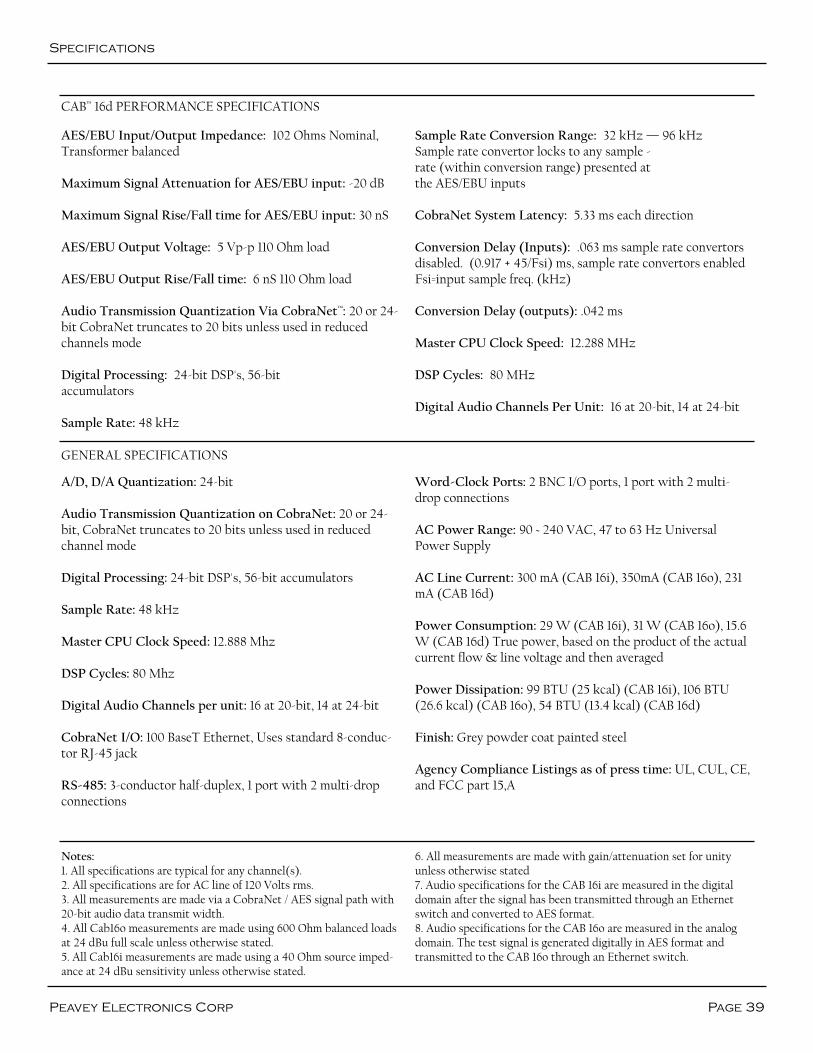
Specifications
Page 39Peavey Electronics Corp
GENERAL SPECIFICATIONS
CAB™ 16d PERFORMANCE SPECIFICATIONS
A/D, D/A Quantization: 24-bit
Audio Transmission Quantization on CobraNet: 20 or 24-bit, CobraNet truncates to 20 bits unless used in reducedchannel mode
Digital Processing: 24-bit DSP's, 56-bit accumulators
Sample Rate: 48 kHz
Master CPU Clock Speed: 12.888 Mhz
DSP Cycles: 80 Mhz
Digital Audio Channels per unit: 16 at 20-bit, 14 at 24-bit
CobraNet I/O: 100 BaseT Ethernet, Uses standard 8-conduc-tor RJ-45 jack
RS-485: 3-conductor half-duplex, 1 port with 2 multi-dropconnections
Word-Clock Ports: 2 BNC I/O ports, 1 port with 2 multi-drop connections
AC Power Range: 90 ~ 240 VAC, 47 to 63 Hz UniversalPower Supply
AC Line Current: 300 mA (CAB 16i), 350mA (CAB 16o), 231mA (CAB 16d)
Power Consumption: 29 W (CAB 16i), 31 W (CAB 16o), 15.6W (CAB 16d) True power, based on the product of the actualcurrent flow & line voltage and then averaged
Power Dissipation: 99 BTU (25 kcal) (CAB 16i), 106 BTU(26.6 kcal) (CAB 16o), 54 BTU (13.4 kcal) (CAB 16d)
Finish: Grey powder coat painted steel
Agency Compliance Listings as of press time: UL, CUL, CE,and FCC part 15,A
AES/EBU Input/Output Impedance: 102 Ohms Nominal,Transformer balanced
Maximum Signal Attenuation for AES/EBU input: -20 dB
Maximum Signal Rise/Fall time for AES/EBU input: 30 nS
AES/EBU Output Voltage: 5 Vp-p 110 Ohm load
AES/EBU Output Rise/Fall time: 6 nS 110 Ohm load
Audio Transmission Quantization Via CobraNet™: 20 or 24-bit CobraNet truncates to 20 bits unless used in reducedchannels mode
Digital Processing: 24-bit DSP's, 56-bitaccumulators
Sample Rate: 48 kHz
Sample Rate Conversion Range: 32 kHz — 96 kHzSample rate convertor locks to any sample -rate (within conversion range) presented atthe AES/EBU inputs
CobraNet System Latency: 5.33 ms each direction
Conversion Delay (Inputs): .063 ms sample rate convertorsdisabled. (0.917 + 45/Fsi) ms, sample rate convertors enabledFsi=input sample freq. (kHz)
Conversion Delay (outputs): .042 ms
Master CPU Clock Speed: 12.288 MHz
DSP Cycles: 80 MHz
Digital Audio Channels Per Unit: 16 at 20-bit, 14 at 24-bit
Notes:1. All specifications are typical for any channel(s).2. All specifications are for AC line of 120 Volts rms.3. All measurements are made via a CobraNet / AES signal path with20-bit audio data transmit width.4. All Cab16o measurements are made using 600 Ohm balanced loadsat 24 dBu full scale unless otherwise stated.5. All Cab16i measurements are made using a 40 Ohm source imped-ance at 24 dBu sensitivity unless otherwise stated.
6. All measurements are made with gain/attenuation set for unityunless otherwise stated7. Audio specifications for the CAB 16i are measured in the digitaldomain after the signal has been transmitted through an Ethernetswitch and converted to AES format.8. Audio specifications for the CAB 16o are measured in the analogdomain. The test signal is generated digitally in AES format andtransmitted to the CAB 16o through an Ethernet switch.

Architectural Acoustics®
PEAVEY ELECTRONICS CORPORATION LIMITED WARRANTYEffective Date: July 1, 1998
What This Warranty CoversYour Peavey Warranty covers defects in material and workmanship in Peavey products purchased and serviced in the U.S.A. and Canada.
What This Warranty Does Not CoverThe Warranty does not cover: (1) damage caused by accident, misuse, abuse, improper installation or operation, rental, product modification orneglect; (2) damage occurring during shipment; (3) damage caused by repair or service performed by persons not authorized by Peavey; (4)products on which the serial number has been altered, defaced or removed; (5) products not purchased from an Authorized Peavey Dealer.
Who This Warranty ProtectsThis Warranty protects only the original retail purchaser of the product.
How Long This Warranty LastsThe Warranty begins on the date of purchase by the original retail purchaser. The duration of the Warranty is as follows:
Product Category Duration
MediaMatrix® DPU, (Excluding Frames), Cinema Processors,Power Amplifiers, Pre-Amplifiers, Mixers, Electronic Crossovers and Equalizers 2 years *(+ 3 years)
Loudspeakers 3 years *(+ 2 years)
Microphones 2 years
Speaker Components (including speakers, baskets, drivers, diaphragm replacement kits and passive crossovers) and all Accessories 90 days
[*Denotes additional warranty period applicable if optional Warranty Registration Card is completed and returned to Peavey by original retail purchaserwithin 90 days of purchase.]
What Peavey Will DoWe will repair or replace (at Peavey's discretion) products covered by warranty at no charge for labor or materials. If the product or componentmust be shipped to Peavey for warranty service, the consumer must pay initial shipping charges. If the repairs are covered by warranty, Peaveywill pay the return shipping charges.
How To Get Warranty Service(1) Take the defective item and your sales receipt or other proof of date of purchase to your Authorized Peavey Dealer or Authorized PeaveyService Center. OR(2) Ship the defective item, prepaid, to Peavey Electronics Corporation, International Service Center, 412 Highway 11 & 80 East, Meridian, MS39301 or Peavey Canada Ltd., 95 Shields Court, Markham, Ontario, Canada L3R 9T5. Include a detailed description of the problem, togetherwith a copy of your sales receipt or other proof of date of purchase as evidence of warranty coverage. Also provide a complete return address.OR
(3) All MediaMatrix® Frames needing repair, should be shipped, prepaid to Peavey Electronics Corporation, International Service Center, 412Highway 11 & 80 East, Meridian, MS 39301.
Limitation of Implied WarrantiesANY IMPLIED WARRANTIES, INCLUDING WARRANTIES OF MERCHANTABILITY AND FITNESS FOR A PARTICULAR PURPOSE, ARE LIM-ITED IN DURATION TO THE LENGTH OF THIS WARRANTY. Some states do not allow limitations on how long an implied warranty lasts, so the above limitation may not apply to you.
Exclusions of DamagesPEAVEY'S LIABILITY FOR ANY DEFECTIVE PRODUCT IS LIMITED TO THE REPAIR OR REPLACEMENT OF THE PRODUCT, AT PEAVEY'SOPTION. IF WE ELECT TO REPLACE THE PRODUCT, THE REPLACEMENT MAY BE A RECONDITIONED UNIT. PEAVEY SHALL NOT BELIABLE FOR DAMAGES BASED ON INCONVENIENCE, LOSS OF USE, LOST PROFITS, LOST SAVINGS, DAMAGE TO ANY OTHEREQUIPMENT OR OTHER ITEMS AT THE SITE OF USE, OR ANY OTHER DAMAGES WHETHER INCIDENTAL, CONSEQUENTIAL OR OTH-ERWISE, EVEN IF PEAVEY HAS BEEN ADVISED OF THE POSSIBILITY OF SUCH DAMAGES.Some states do not allow the exclusion or limitation of incidental or consequential damages, so the above limitation or exclusion maynot apply to you.
This Warranty gives you specific legal rights, and you may also have other rights which vary from state to state.
If you have any questions about this warranty or service received or if you need assistance in locating an Authorized Service Center, please con-tact the Peavey International Service Center at (601) 483-5365 / Peavey Canada Ltd. at (905) 475-2578.
Features and specifications subject to change without notice.
CAB™
16 Series User Manual
Page 40 http://aa.peavey.com copyright 2000 All Rights Reserved

Features and Specifications subject to change without notice.A product of Peavey Electronics Corporation
711 A Street / Meridian, MS 39301 / USA / (601) 483-5376 / FAX (601) 486-1678http://aa.peavey.com
Copyright 2000 All Rights ReservedPrinted in USA 4/2000


