+ All Categories
Home > Documents > Cabinet Location Plan -...

Cabinet Location Plan -...

Date post: 15-Jul-2019
Category:
Upload: nguyenminh
View: 213 times
Download: 0 times
Share this document with a friend
16
Air Handler 1A A1 A2 A3 A4 A5 A6 A7 1B 1C 1D 1E 1F 1G 1H 1I 1J 1K 1L 1M PDU Power Panel PDU Power Panel Air Handler A8 A9 2A 2B 2C 2D 2E 2F 2G 2H 2I 2J 2K 2L 2M 3A 3B 3C 3D 3E 3F 3G 3H 3I 3J 3K 3L 3M 4A 4B 4C 4D 4E 4F 4G 4H 4I 4J 4K 4L 4M 5A 5B 5C 5D 5E 5F 5G 5H 5I 5J 5K 5L 5M 6A 6B 6C 6D 6E 6F 6G 6H 6I 6J 6K 6L 6M Up Data Center Storage / Fit-Up Square Feet ____ Square Meters Cabinet front face Data Center Square Feet ____ Square Meters 12 1 SAN disk storage option A Cabinet Symbol Key Network Row Network Substation Server Cabinet Cable storage shelving Breaker panels A1 1A 1B FIG.01 Cabinet Location Plan Not To Scale SAN disk storage option B - 09 - 13
Transcript

Air

Han

dler

1AA

1

A2

A3

A4

A5

A6

A7

1B 1C 1D 1E 1F 1G 1H 1I 1J 1K 1L 1M

PDU

Pow

erPa

nel

PDU

Pow

erPa

nel

Air

Han

dler

A8

A9

2A 2B 2C 2D 2E 2F 2G 2H 2I 2J 2K 2L 2M

3A 3B 3C 3D 3E 3F 3G 3H 3I 3J 3K 3L 3M

4A 4B 4C 4D 4E 4F 4G 4H 4I 4J 4K 4L 4M

5A 5B 5C 5D 5E 5F 5G 5H 5I 5J 5K 5L 5M

6A 6B 6C 6D 6E 6F 6G 6H 6I 6J 6K 6L 6M

Up

Dat

a C

ente

rSt

orag

e / F

it-U

p

Squ

are

Feet

__

__ S

quar

e M

eter

s

Cab

inet

fr

ont f

ace

Dat

a C

ente

r

Squ

are

Feet

__

__ S

quar

e M

eter

s

12

1

SAN

dis

k st

orag

e op

tion

AC

abin

et S

ymbo

l Key

Net

wor

k R

ow

Net

wor

k Su

bsta

tion

Serv

er C

abin

et

Cab

le s

tora

ge s

helv

ing

Bre

aker

pan

els

A1

1A 1B

FIG

.01

Cab

inet

Loc

atio

n Pl

anN

ot T

o Sc

ale

SAN

dis

k st

orag

e op

tion

B

- 09

- 13

Air

Han

dler

L

L2 ft

.

61 cm.

PDU

Pow

erPa

nel

PDU

Pow

erPa

nel

Air

Han

dler

Up

Dat

a C

ente

rSt

orag

e / F

it-U

p

Dat

a C

ente

r

12

1

FIG

.02

Floo

r Tile

Sym

bol K

ey

Floo

r tile

lift

er o

n w

all m

ount

ed s

tora

ge b

rack

et

Perf

orat

ed ti

le w

ith a

djus

tabl

e vo

lum

e da

mpe

rs

L

Not

ched

tile

with

8 in

. x 8

in. (

20 c

m. x

20

cm.)

cuto

ut c

ente

red

on o

ne e

dge

At t

he N

etw

ork

row

and

N

etw

ork

Subs

tatio

ns,

prov

ide

8 in

. x 8

in.

(20

cm. x

20

cm.)

cuto

uts

in fi

eld

as

requ

ired

to a

lign

with

ve

rtica

l wire

man

ager

s.

Floo

r Tile

Loc

atio

n Pl

anN

ot T

o Sc

ale

Air

Han

dler

1A2A

3A4A

5A6A

A1

A2

A3

A4

A5

A6

A7

1B 1C 1D 1E 1F 1G 1H 1I 1J 1K 1L 1M

2B 2C 2D 2E 2F 2G 2H 2I 2J 2K 2L 2M

3B 3C 3D 3E 3F 3G 3H 3I 3J 3K 3L 3M

4B 4C 4D 4E 4F 4G 4H 4I 4J 4K 4L 4M

5B 5C 5D 5E 5F 5G 5H 5I 5J 5K 5L 5M

6B 6C 6D 6E 6F 6G 6H 6I 6J 6K 6L 6M

RBFP

5 55 52 22 2

2222

2 22 2

2 22 2

2222

2 22 2

2222

2 22 22 22 22 22 22 22 22 22 22 22 2

2 22 22 22 22 22 22 22 22 22 22 22 2

2 22 22 22 22 22 22 22 22 22 22 22 2

2 22 22 22 22 22 22 22 22 22 22 22 2

2 22 22 22 22 22 22 22 22 22 22 22 2

2 22 22 22 22 22 22 22 22 22 22 22 2

2222

2222

2222

2222

2222

2222

BR

BR

RB

PDU

Pow

erPa

nel

PDU

Pow

erPa

nel

Air

Han

dler

A8

A9

RB

5 55 55 55 55 55 55 55 55 55 55 55 5

Up

Dat

a C

ente

rSt

orag

e / F

it-U

p

Dat

a C

ente

r

12

1

FIG

.03

Tel

epho

ne

Em

erge

ncy

Pow

er O

ff (E

PO)

Blu

e lig

ht (I

ndic

ates

gen

erat

or p

ower

)

Red

ligh

t (In

dica

tes

UPS

pow

er)

Fire

sup

pres

sion

con

trol

220

volt

pow

er w

hip

(NE

MA

L6-

30R

on

dedi

cate

d ci

rcui

t)

220

volt

pow

er w

hip

(T&

B 9

C63

U2T

on

dedi

cate

d ci

rcui

t)

2 3 4 522

0 vo

lt po

wer

whi

p (P

&S

WA

E36

1306

on

dedi

cate

d ci

rcui

t)

BP FREle

ctri

cal S

ymbo

l Key

120

volt

pow

er w

hip

(NE

MA

5-2

0R d

oubl

e du

plex

w/ 2

ded

icat

ed c

ircu

its)

120

volt

wal

l out

let

not o

n U

PS

220

volt

pow

er w

hip

(Rus

sells

toll

9C54

U2T

on

dedi

cate

d ci

rcui

t)E

lect

rica

l Loc

atio

n Pl

anN

ot T

o Sc

ale

SAN

dis

k st

orag

e op

tion

BSA

N d

isk

stor

age

optio

n A

1AA

1

A2

A3

A4

A5

A6

A7

1B 1C 1D 1E 1F 1G 1H 1I 1J 1K 1L 1M

A8

A9

2A 2B 2C 2D 2E 2F 2G 2H 2I 2J 2K 2L 2M

3A 3B 3C 3D 3E 3F 3G 3H 3I 3J 3K 3L 3M

4A 4B 4C 4D 4E 4F 4G 4H 4I 4J 4K 4L 4M

5A 5B 5C 5D 5E 5F 5G 5H 5I 5J 5K 5L 5M

6A 6B 6C 6D 6E 6F 6G 6H 6I 6J 6K 6L 6M

Up

Dat

a C

ente

rSt

orag

e / F

it-U

p

Dat

a C

ente

r

12

1

Cab

inet

Sym

bol K

eyN

etw

ork

Row

Cab

inet

Net

wor

k Su

bsta

tion

Serv

er C

abin

et

A1

1A 1B

FIG

.04

Net

wor

k an

d SA

N

conn

ectio

ns fr

om N

etw

ork

Subs

tatio

ns to

Net

wor

k R

ow

Net

wor

k an

d SA

N c

onne

ctio

ns

from

Net

wor

k Su

bsta

tions

to

Serv

er C

abin

et L

ocat

ions

SAN

dis

k co

nnec

tions

op

tion

ASA

N d

isk

conn

ectio

ns

optio

n B

Dat

a R

outin

g D

iagr

amN

ot T

o Sc

ale

Server Cabinets

Power whip head Multimedia Box

36 in. (91 cm.) service loop at each data whip

FIG.05

Raised floor

Under Floor Power and Cable DetailNot To Scale

Power whips are located directly below Server Cabinets.

Power whip heads and multimedia boxes are located under floor behind Server Cabinets.

Data runs are located under floor in front of next Server Row.

Component location detail

Secure power and data cables to raised floor columns with hook and loop cable ties.

Dress whips and data cables neatly with hook and loop cable ties.

Provide 36 in. (91 cm.) service loops on each power and data whip.

Power to each Server Cabinet Location is supplied from two separate power panels connected to separate PDUs.

FIG.06

At each Server Cabinet Location, provide power whips with 24 in. (61 cm.) extra length.

Power and Data Cable DetailNot To Scale

Additional fiber multimedia box at SAN disk row only

ROW 2 BOX CFIBER

02

05

03

06

01

04

50 MICRON LC

08

1109

07

10

12

0509

0201

0403

06 0708 10

1112

21

1817

2019

22 2324

ROW 2 BOX CCOPPER

ROW 2 BOX CCOPPER

13 1415 16

PDU 1 PANEL A

L6-30

2 , 4

PDU 2 PANEL B

L6-30

2 , 4

Power whip labeling detail1

Copper multimedia box labeling detail2 3 Fiber multimedia box labeling detail

Note:Each cabinet location is serviced by two different PDUs.

Not To Scale

Under Floor Labeling Details

FIG.07

See

Det

ail D

raw

ings

for

Spec

ific

Com

pone

nt L

ayou

t

FIG.08

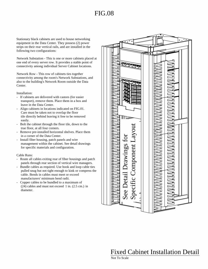
Stationary black cabinets are used to house networking equipment in the Data Center. They possess (2) power strips on their rear vertical rails, and are installed in the following two configurations:

Network Substation - This is one or more cabinets placed at one end of every server row. It provides a stable point of connectivity among individual Server Cabinet locations.

Network Row - This row of cabinets ties together connectivity among the room's Network Substations, and also to the building's Network Room outside the Data Center.

Installation:- If cabinets are delivered with castors (for easier transport), remove them. Place them in a box and leave in the Data Center.- Align cabinets in locations indicated on FIG.01. Care must be taken not to overlap the floor tile directly behind leaving it free to be removed easily.- Bolt the cabinet through the floor tile, down to the true floor, at all four corners.- Remove pre-installed horizontal shelves. Place them in a corner of the Data Center.- Install fiber housing, patch panels and wire management within the cabinet. See detail drawings for specific materials and configuration.

Cable Runs:- Route all cables exiting rear of fiber housings and patch panels through rear section of vertical wire managers.- Bundle cables as required. Use hook and loop cable ties pulled snug but not tight enough to kink or compress the cable. Bends in cables must meet or exceed manufacturers' minimum bend radii.- Copper cables to be bundled to a maximum of (24) cables and must not exceed 1 in. (2.5 cm.) in diameter.

Fixed Cabinet Installation DetailNot To Scale

Cab

inet

s eq

uipp

ed w

ith (2

) ve

rtica

l pow

er s

trips

atta

ched

in

side

of r

ear s

tiles

.

Reserved for network gear

A4

A3

A2

A1 Fiber & copper to

Network Room & Storage/Build Room

Fiber to Network Substations

Copper to Network Substations

A5

A6

Expansion spaceA

7A

8A

9A

10 SAN disk frame

SAN fiber to disk storage (option A)

Expansion space

Expansion space

FIG

.09

SAN disk frame

- 1011-

- 12

12 in

. (30

.5 c

m.)

Ver

tical

w

ire m

anag

er

Net

wor

k R

ow E

leva

tion

Not

To

Scal

e

1 7

104

5 11

3

2

9

8

SINGLEMODEA1/NR

1-6 7-12

1 7

104

5 11

3

2

9

8

MULTIMODEA1/NR

1-6 7-12

A1/NR

1 2 3 4 5 6 7 8 9 10 11 12 13 14 15 16 17 18 19 20 21 22 23 24

1 2 3 4 5 6 1 2 3 4 5 6

A1/BUILD

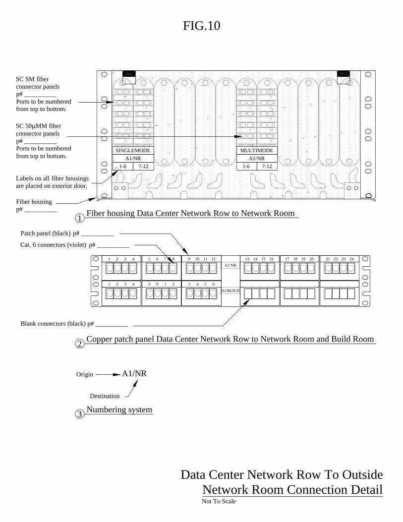
SC SM fiber connector panels p# __________Ports to be numbered from top to bottom.

Fiber housing p# __________

SC 50µMM fiber connector panels p# __________Ports to be numbered from top to bottom.

Labels on all fiber housings are placed on exterior door.

Patch panel (black) p# __________

Cat. 6 connectors (violet) p# __________

FIG.10

Data Center Network Row To Outside Network Room Connection DetailNot To Scale

Blank connectors (black) p# __________

2 Copper patch panel Data Center Network Row to Network Room and Build Room

Fiber housing Data Center Network Row to Network Room 1

Destination

Origin A1/NR

3 Numbering system

NETWORK 50 MICRON MM

A2/3A A2/4AA2/1A A2/2A

A2 / NETWORK SUBSTATIONS

Fiber housing p# __________

LC 50µMM fiber connector panels p# __________ Ports to be numbered from top to bottom.

Fiber housings, multimode connections DC Network Row to Network Substations 1

Fiber Housing Connections

2

1

2

Fiber housing schedule for connector panels

Note:This detail shows fiber housing # 1 as an example of typical connector panel and labeling configuration. See schedule below for layout of other fiber housings.

1

A2

A2/

1A

2 A2/

2A

A2/

3A

A2/

4A

Numbering system3

A2/1A

Labels on all fiber housings are placed on exterior door.

FIG.11

A2/

6A

A2/

5A

Origin

Destination

Network Row Fiber DetailNot To Scale

A4/1A

2 3 4 5 6 7 8 9 10 11 12 13 14 15 16 17 18 19 20 21 22 23 24

1 2 3 4 5 6 7 8 9 10 11 12

1

A4/2A

13 14 15 16 17 18 19 20 21 22 23 24

Copper patch panel DC Network Row to Network Substations 1

Patch Panel Connection destinations

2

1

2 Copper patch panel schedule

Note:This detail shows patch panel # 1 as an example of typical connector and labeling configuration. See schedule below for layout of other patch panels.

1

A4

FIG.12

23

A4/1A

A4/2A

A4/4A

A4/3A

3A4/6A

A4/5A

Copper patch panel (black) p# __________

Cat. 6 connectors (white)p# __________

Destination

Origin A4/1A

3 Numbering systemNetwork Row Copper DetailNot To Scale

FIG.13

8 in. (20.3 cm.) Vertical wire manager p# __________

6 in. (15.2 cm.) Vertical wire manager p# __________

Black cabinet equipped with (2) vertical power strips attached inside of rear stiles.

1A

14-

-15

-16

Network Substations DetailNot To Scale

Horizontal passthrough wire manager p# __________

Networking devices

1A/1D

1A / DROP BOXES

1A/1G 1A/1I 1A/1J 1A/1K 1A/1M1A/1H 1A/1L1A/1B 1A/1C

NETWORK 50 MICRON MM

1A/1E 1A/1F

Fiber housing p# __________

LC 50µMM fiber connector panels p# __________Ports to be numbered from top to bottom.

Labels on all fiber housings are placed on exterior door.

Fiber housing, 50µ connections Network Substation to Server Cabinet Locations 1

Fiber Housing Connections

1

2 Fiber housing schedule for connector panels

1

1A

FIG.14

1A/1

B

1A/1

D

1A/1

E

1A/1

G

1A/1

C

1A/1

H

1A/1

F

1A/1

I

1A/1

J

1A/1

K

1A/1

L

1A/1

M

Not To ScaleNetwork Substation Fiber Detail

Origin

Numbering system3

1A/1H

Destination

1A/A2

NET SM

1A/A2

NET 50 MICRON MM

1A/A8

SAN 50 MICRON MM

FIG.15

Network Substation To Network Row DetailNot To Scale

Fiber connections, Network Substation to Network Row

Place labels on exterior of fiber housing door.

Blank bezel provided with fiber housing

Corning fiber housing p# ____________

LC 50µMM fiber connector panels p# __________Ports to be numbered from top to bottom.

LC SM fiber connector panels p# _________ Ports to be numbered from top to bottom.

Destination

1A/A2

2 Numbering system

Origin

1

1A/A4

2 3 4 5 6 7 8 9 10 11 12 13 14 15 16 17 18 19 20 21 22 23 24

1 2 3 4 5 6 7 8 9 10 11 12

1

1A/1B 1A/1C

1 2 3 4 5 6 7 8 9 10 11 12

Copper patch panel, connections Network Substation to Network Row and Server Cabinet Locations1Patch Panel Connection destinations

2

1

2 Copper patch panel schedule

1

1A

FIG.16

234

1A/A4

1A/1B

1A/1F

1A/1D

31A/1J

1A/1H

4 1A/1L

Patch panel (black)p# __________

To Network RowCat. 6 connectors (black) p# __________

Not To Scale

Network Substation Copper Detail

Origin

Numbering system3

1A/1H

Destination

To Data Drop BoxesCat. 6 connectors (white)p# __________

Note:This detail shows patch panel # 1 as an example of typical connector and labeling configuration. See schedule below for layout of other patch panels.

1A/1M

1A/1I

1A/1K

1A/1E

1A/1G

1A/1C

1U patch panel (black)p# __________


Recommended