17
Document No: TG-001 Issue Date: 14/07/2012 Version: 2.8 Cable Entry Guide

Document No: TG-001
Issue Date: 14/07/2012
Version: 2.8
Cable Entry Guide

2
Document Control Sheet
Record of Issue
Issue Date Description
1.0 14-Jan-08
2.0 14-Feb-09 Removed references to different types of conduit size.
2.1 20-Mar-09 General updates. Telecommunications Cabling Advice.
2.2 2-Sep-2009 Update of Conduit sizing & Pay TV requirements
2.3 16-Apr-2010 Minor updates and corrections
2.4 4-Mar-2011 Added address table to Checklist
2.5 23-May-2011
Added Earth and NTD location Information, edits to OptiComm Customer Contact Information Desk
2.6 25 Nov 2011
Changed reference to 20mm/Add references re: contractors not hauling Lead In Fibres
2.7 14-May-2012
Remove watermark, update contact details in Checklist
2.8 18-July-2012
Addition of termination of cable ends. Removal of reference to Opticomm providing lead in conduit at additional cost, updated checklist to new standard, clarification of power cable.
Acceptance and Approval
Issue Name Position Signature Date
1.0 S. Davies GM, Operations 14-Jan-08
2.0 S. Davies GM, Operations 14-Feb-09
2.1 S. Davies GM, Operations 20-Mar-09
2.3 S. Davies GM, Operations 23-Apr-2010
2.4 S. Davies GM, Operations 04-Mar-2011
2.5 S. Davies GM, Operations 23-May-2011
2.6 S. Davies GM, Operations 25-Nov-2011
2.7 S Davies GM, Operations 14-May-2012
2.8 S Davies GM, Operations 19-July-2012
In the event of any enquiries with respect to this document, please contact:
Name Position Email
S. Davies CTO [email protected]

3
Copyright Statement
Copyright of this material resides with Opticomm Co Pty Ltd. Apart from any fair dealing for the purposes of private study, research, criticism or review, as permitted under the Copyright Act 1968, no part may be reproduced or reused for any purposes whatever without prior written permission of the owner.
Warning! All customer cabling work MUST be performed by a registered cabler. If a cabler is registered, they will have a card which proves that they can legally perform cabling work.
The cabling work must comply with the Australian Standards and Wiring Rules, which detail the minimum requirements for cabling installations to ensure that network integrity and the health and safety of end-users, other cablers and carrier personnel is protected.
The cabling is required to have adequate separation or segregation from electrical cabling to avoid creating a dangerous situation.
Failure to use a registered telecommunications cabler may result in fines of up to $13,200.

4
1.0 PURPOSE
The aim of this document is to outline what is required for homeowners and their builders, or developers to connect to telecommunication networks based on Fibre to the Home (FTTH) technology.
2.0 SCOPE
This document extends to detached or semi-detached buildings that are being built for residential or small business use. It covers requirements of connection from the telecommunications pit to the Home Distribution Unit.
3.0 THINGS YOU SHOULD KNOW
3.1 Introduction
Modern technology has brought many changes to the way we live, specifically in communications where many new services are being introduced that require high-speed delivery infrastructure. New Digital Telephone, Ultra-High Speed Internet and Television Services (including pay and free to air) offer greatly enhanced performance when compared to older technology. To accommodate these changes, residential developments must move forward with technology and provide infrastructure that will have the capacity for not only today but also for future technological advancements.
In standard residential areas, the incumbent carrier meets the basic communication needs of the community. At OptiComm, our commitment is about being at the forefront of the education and broadband revolution, and as such we provide advanced fibre optic communication infrastructure as a replacement for the traditional copper network.
3.2 Services
Fibre communication network will provide a range of services, including reticulation of the analogue and digital free to air television signals, Pay TV, Ultra-HighSpeed Internet, and a Standard Telephone Service. Additional services, such as Community Intranet, security monitoring, gate control, and new entertainment services such as IPTV and Video-on-Demand, are all possibilities with this latest technology.
3.3 Connection
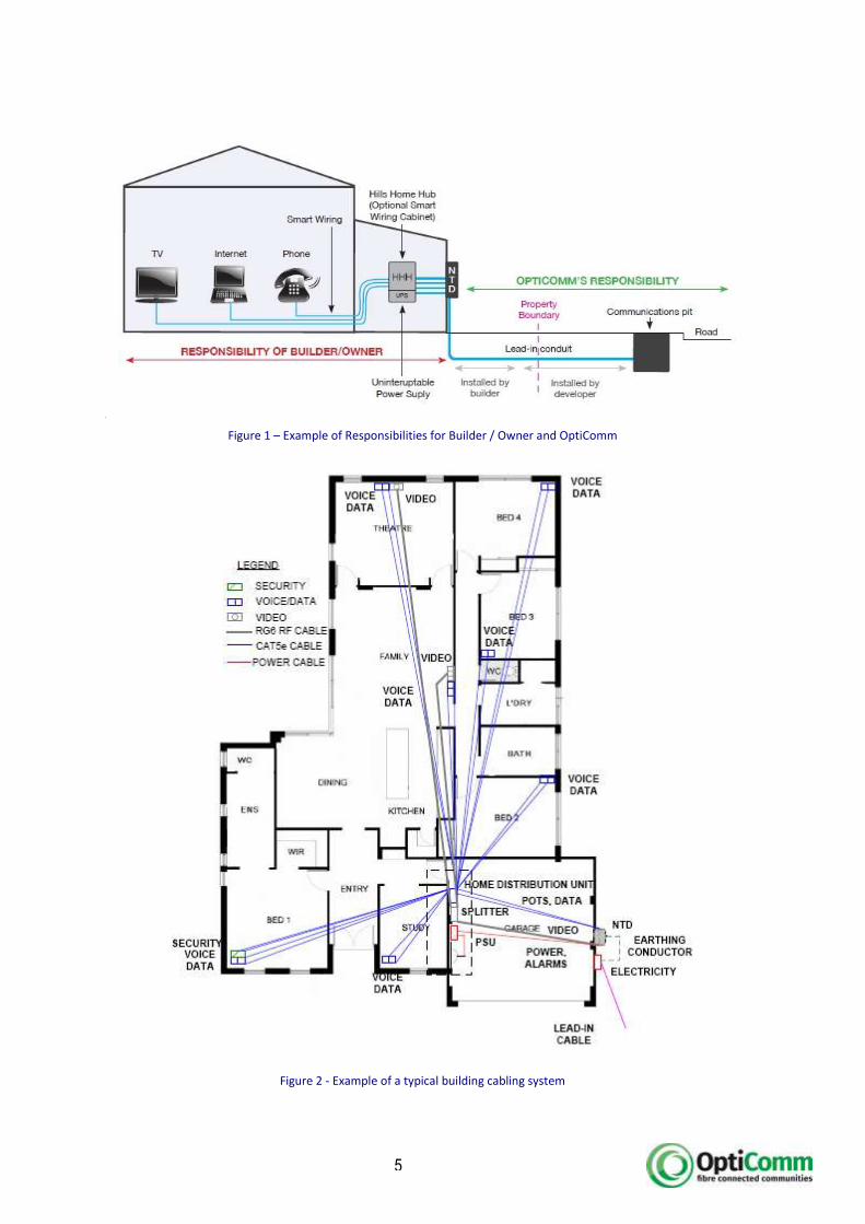
A fibre optic enabled community allows for you to connect to the network that runs past your property. A fibre optic lead in cable connects to a device on the external wall of your home. This is called a Network Termination Device (NTD) and it is where the optical signal (light) is converted to an electrical signal and retransmitted on twisted pair and coaxial cable to your Home Distribution Unit (HDU). The following illustration shows the various elements of the connection to the Optical Fibre Network and the in home cabling and the responsibilities of both OptiComm and the Builder/owner.
5
Figure 1 – Example of Responsibilities for Builder / Owner and OptiComm
Figure 2 - Example of a typical building cabling system

6
To be able to connect to the OptiComm Optical Fibre Network, you must wire your home in accordance with the specifications provided. This specification outlines the materials to use and recommends smart wiring in your home. Your Builder / Telecommunications Contractor must follow the specifications and not substitute “equivalent” materials at any point in time. If you are about to commence construction, wiring your home correctly during initial construction will save you considerable expense when compared to the cost of rewiring your home once you have moved in.
It is also mandatory during construction of your home that your Builder or Telecommunications Contractor provides the appropriate continuous vessel between your home and the communications infrastructure running down the street. This vessel or “conduit” will be used to pull through a fibre optic cable and connect your home to the rest of the world, enabling you to receive telephone, internet and television services.
3.5 Outdoor Antennas
In your community the Local Structure Plan and Restrictive Covenants may prevent you from installing an outdoor antenna for television reception. However once your home is connected to the fibre network, you will receive perfect quality analogue and standard and high definition digital television signals which can be reticulated throughout your home.
3.6 Satellite Dishes
As with outdoor antennas restrictive covenants may restrict the installation of satellite dishes. The fibre optic network will reticulate the major Pay-TV channels throughout your estate enabling you to deal directly with your preferred operator and providing superior quality reception.
3.7 More Information
As a homeowner you are responsible for organizing installation of your connection and all costs associated with that connection. For more information contact the people below:
For more information contact the
OptiComm Customer Connection Information Desk
on 1300 137 800
or via email [email protected]
For multi dwelling lots please contact Opticomm as you will require additional services and pipework installed (at your cost) within the property boundary.
7
4.0 EQUIPMENT DESCRIPTION
4.1 Conduit
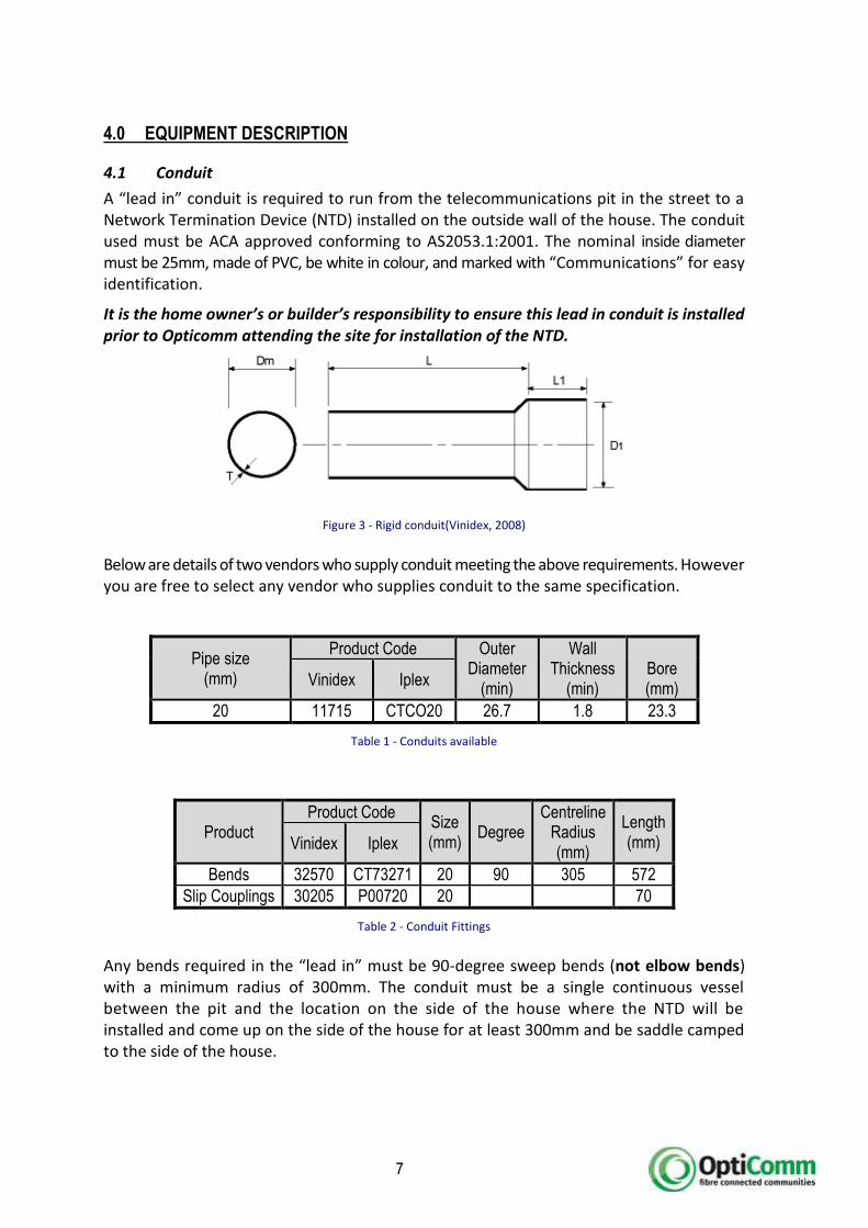
A “lead in” conduit is required to run from the telecommunications pit in the street to a Network Termination Device (NTD) installed on the outside wall of the house. The conduit used must be ACA approved conforming to AS2053.1:2001. The nominal inside diameter must be 25mm, made of PVC, be white in colour, and marked with “Communications” for easy identification.
It is the home owner’s or builder’s responsibility to ensure this lead in conduit is installed prior to Opticomm attending the site for installation of the NTD.
Figure 3 - Rigid conduit(Vinidex, 2008)
Below are details of two vendors who supply conduit meeting the above requirements. However you are free to select any vendor who supplies conduit to the same specification.
Pipe size (mm)
Product Code Outer Diameter
(min)
Wall Thickness
(min)
Bore (mm)
Vinidex Iplex
20 11715 CTCO20 26.7 1.8 23.3
Table 1 - Conduits available
Product Product Code
Size (mm)
Degree
Centreline Radius (mm)
Length (mm) Vinidex Iplex
Bends 32570 CT73271 20 90 305 572
Slip Couplings 30205 P00720 20 70
Table 2 - Conduit Fittings
Any bends required in the “lead in” must be 90-degree sweep bends (not elbow bends) with a minimum radius of 300mm. The conduit must be a single continuous vessel between the pit and the location on the side of the house where the NTD will be installed and come up on the side of the house for at least 300mm and be saddle camped to the side of the house.

8
Opticomm normally installs a 20mm starter conduit leading out of the telecommunications pit to the property boundary. The builder should locate this starter conduit, then glue and couple the conduit they are installing.
During building construction, conduits should be installed for the NTD cabling at the owner’s cost. These must be ready for use but not provide a path for water or termites to enter the building.
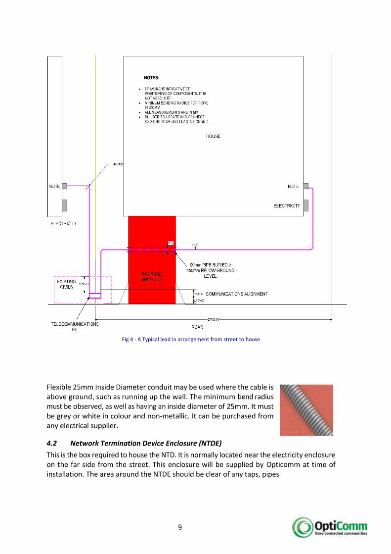
If the lead in conduit is to be installed under a driveway or retaining wall, it is recommended being place within a 90mm storm water or irrigation pipe. This functions for two purposes;
To protect the communications conduit from damage;
To allow the future installation of other services (e.g. water reticulation pipes and wires)
Ø 90
Ø 25
MIN COVER 450
LIMESTONE BASE
EARTH
DRIVEWAY
9
Fig 4 - A Typical lead in arrangement from street to house
Flexible 25mm Inside Diameter conduit may be used where the cable is above ground, such as running up the wall. The minimum bend radius must be observed, as well as having an inside diameter of 25mm. It must be grey or white in colour and non-metallic. It can be purchased from any electrical supplier.
4.2 Network Termination Device Enclosure (NTDE)
This is the box required to house the NTD. It is normally located near the electricity enclosure on the far side from the street. This enclosure will be supplied by Opticomm at time of installation. The area around the NTDE should be clear of any taps, pipes
10
4.3 Network Termination Device (NTD)
Network Termination Device is also known as an Optical Network Termination (ONT). This marks a network boundary point connecting the homeowner’s equipment to the fibre optic enabled community.
4.4 Power Supply Unit (PSU)
The homeowner must supply a 10 Amp 240 Volt General Purpose Outlet (GPO) to power a basic plug pack or PSU for the NTD. The PSU is usually located near the Home Distribution Unit located in the garage and uses the cabling low voltage cable installed between the HDU and NTD.
The PSU must be installed between 1700mm and 350mm above the floor level of the building. 1000m to 1300mm is ideal. For adequate ventilation and access to the unit allow a space of 340W x 295H x 125D inside the HDU.
4.5 Fibre Optic Cable
A pre-connectorised fibre cable will be installed from the network pit to the customer premises. This cable will be supplied and installed by OptiComm at time of connecting the house to the rest of the network.
Warning:
Under no circumstances should the resident, builder or electrical contractor attempt to install the optical fibre lead in cable from the OptiComm Network pit located in the street to the location near where the meter box via the lead in conduit. The Optical Fibre Lead in cable is relatively inflexible and if it is damaged by unauthorised parties its replacement cost will be billed to the resident and paid for before the service connection will be completed. Typical cost for this work is in the vicinity of $440.00 including GST.

11
5.0 BUILDING ENTRY ARRANGEMENTS
5.1 Conduit
The conduit must enter the NTDE to be terminated before it enters the house via a cavity in the brick wall. The rigid lead-in pipe can be replaced with flexible corrugated conduit near the NDT if it can be sealed from water and termite damage. Otherwise a conduit bending tool can be used to shape the rigid conduit to be installed. Either condition must provide a smooth path for the fibre with bends having minimum radius of
305mm.
5.2 Lead in
The lead in is not to go through the concrete slab. Underground, it is to be rigid pipe and must connect properly to the existing start pipe coming from the communications pit. A coupler or bell end must be used to connect the pipe together with appropriate solvent cement. Bends with a minimum radius of 305mm must be used.
Figure 6 - Lead In
The lead in must be installed in such a way that it has minimal impact on the property. Whenever possible, the path must be underground until it is close to the NDTE. Conduit must not cross over the top of structures like retaining walls.
5.3 Communications Pit
Every effort should be made to keep the communications pit on the boundary easement accessible at all times. This will aid installation and maintenance of the network.
R 3
05m
m
MIN 25mm ID Telecommunications conduit
Fibre LIA
NTD
Ground Level
Course Work
Slab
MIN 300mm Cover
Figure 5 - Conduit entry to house
Fibre LIA
NTD
Course Work
Internal cabling to roof Space
Internal cabling Entry.
Hole upwards angle to
prevent moisture ingress

12
Consider landscaping of the property and the level of the ground. Contact Opticomm if you wish to raise the ground level above the pit level.
Any damage to the pit servicing your property will be repaired by Opticomm at your cost, so ensure your builder takes care not to cover, damage or cause disruption to the telecommunications pit.
5.4 NTDE Position
After construction of the building is complete, OptiComm will install the NTDE on your home, near the meter box.
The NTDE must be installed on the outside of the building that the services are to be provided to. This cannot be a separate structure such as a detached building, separate garage or fence. Your builder should install the inside telecommunication cabling and present the cables at an approximate location near the meter box for termination onto the NTD located inside the NTDE.
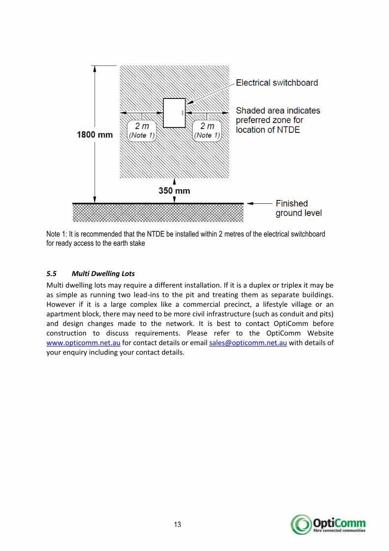
The NTDE will be mounted no lower than 350mm from ground level and no higher than 1800mm to the top of the enclosure. The enclosure dimensions are 400 mm (H) x 300 mm (W) x 150 mm (D). The conduit entry is always from the bottom of the enclosure. The internal cabling pre-wire exit point is best prepared so that it will enter via the rear of the enclosure in a location in the bottom right hand corner of the enclosure.
It is important that the builder takes into consideration the location of the proposed exit point for cabling from the wall and also the location of the lead in conduit at the wall along with other services that may also be located in this vicinity. eg: Hot Water Systems, water taps, gas meters, reticulation timer enclosures and any other externally mounted items.
Please note that at some OptiComm Estates alternate NTDE’s are installed. These include the following:
Single Door with separate internal compartments that house Telecommunications interface cable terminations and the NTD
Dual Door Combo unit that houses Electricity Supply Meters accessible from one door and the NTD from the other door
Triple Door Combo unit that houses Electricity Supply Meters etc via the top door, NTD from the middle door and Gas Meter via the lower door
Please check with the Estate Developer or Sales Centre to ascertain whether an alternate NTDE is required.
13
Note 1: It is recommended that the NTDE be installed within 2 metres of the electrical switchboard for ready access to the earth stake
5.5 Multi Dwelling Lots
Multi dwelling lots may require a different installation. If it is a duplex or triplex it may be as simple as running two lead-ins to the pit and treating them as separate buildings. However if it is a large complex like a commercial precinct, a lifestyle village or an apartment block, there may need to be more civil infrastructure (such as conduit and pits) and design changes made to the network. It is best to contact OptiComm before construction to discuss requirements. Please refer to the OptiComm Website www.opticomm.net.au for contact details or email [email protected] with details of your enquiry including your contact details.

14
6.0 CABLING REQUIREMENTS TO NTD
6.1 Introduction
It is the home owner’s / builder’s responsibility to ensure all appropriate cabling is provided from the Home Distribution Unit or Wall Outlet locations to the Network Termination Device. While not necessary, these cables can be run inside a flexible or rigid conduit.
ALL CABLES MUST BE TERMINATED BOTH ENDS, TESTED AND LABELLED
6.2 Earthing
The Network Termination Device Enclosure must be earthed separately to the building’s electrical earthing system. An electrician must provide a suitable earthing conductor and install as a minimum a single 2.5 sq mm green/yellow earth wire from the earth electrode to the proposed location of the NTDE. The figure below, extracted from AS/ACIF S009, shows acceptable methods of connecting the NTDE to the building earth. OptiComm’s preference is for the NTDE to be earthed in accordance to Method 3. The wire shall be connected to the earth stake, by the electrician, with a suitable additional earth clamp. The earth wire may be run internal to the wall cavity or via surface conduit from the Earth Stake. The earth cable shall be indelibly labelled at the earth stake end “Telecommunications Bonding Conductor”. OptiComm will connect the earth wire at time of installation of the NTDE.
15
6.3 General Purpose Outlet
To power the NTD, OptiComm will install a Power Supply Unit (PSU) inside your home, near the wiring cabinet. It is a requirement to ensure you have a 240 volt GPO installed next to your wiring cabinet or other suitable location so it can power the NTD and the equipment inside your cabinet.
6.4 Power Cable
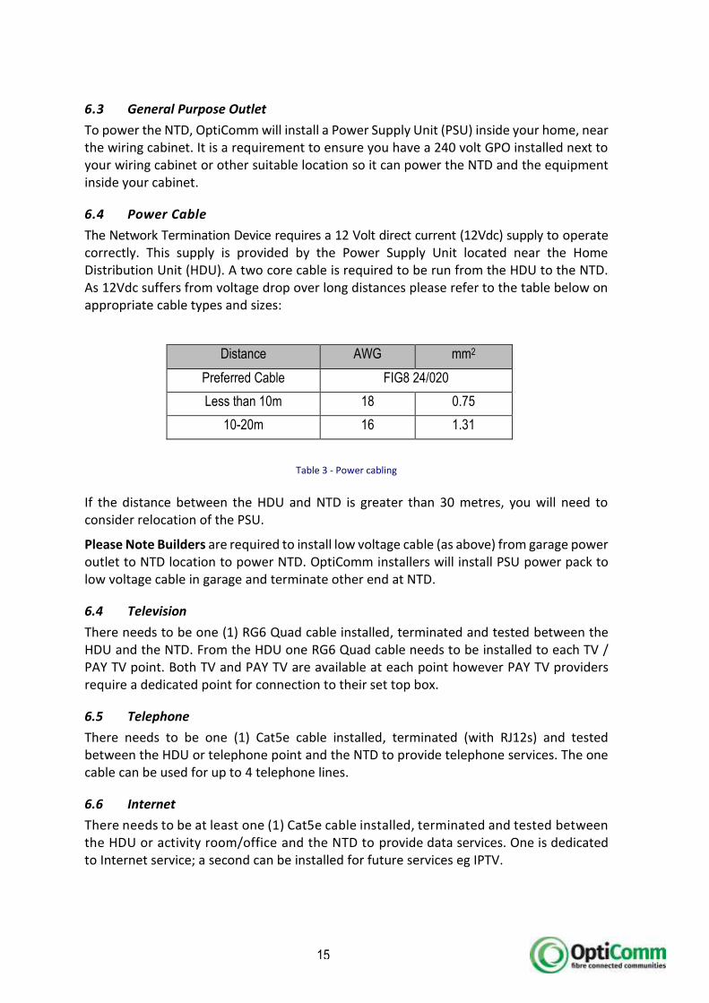
The Network Termination Device requires a 12 Volt direct current (12Vdc) supply to operate correctly. This supply is provided by the Power Supply Unit located near the Home Distribution Unit (HDU). A two core cable is required to be run from the HDU to the NTD. As 12Vdc suffers from voltage drop over long distances please refer to the table below on appropriate cable types and sizes:
Distance AWG mm2
Preferred Cable FIG8 24/020
Less than 10m 18 0.75
10-20m 16 1.31
Table 3 - Power cabling
If the distance between the HDU and NTD is greater than 30 metres, you will need to consider relocation of the PSU.
Please Note Builders are required to install low voltage cable (as above) from garage power outlet to NTD location to power NTD. OptiComm installers will install PSU power pack to low voltage cable in garage and terminate other end at NTD.
6.4 Television
There needs to be one (1) RG6 Quad cable installed, terminated and tested between the HDU and the NTD. From the HDU one RG6 Quad cable needs to be installed to each TV / PAY TV point. Both TV and PAY TV are available at each point however PAY TV providers require a dedicated point for connection to their set top box.
6.5 Telephone
There needs to be one (1) Cat5e cable installed, terminated (with RJ12s) and tested between the HDU or telephone point and the NTD to provide telephone services. The one cable can be used for up to 4 telephone lines.
6.6 Internet
There needs to be at least one (1) Cat5e cable installed, terminated and tested between the HDU or activity room/office and the NTD to provide data services. One is dedicated to Internet service; a second can be installed for future services eg IPTV.

Thank-you for your interest in connecting to the OptiComm Fibre Connected Community – Australia’s fastest and most
advanced fibre optic network. As a member of this community you will be able to receive all your broadband, telephone
and entertainment services1 over a single fibre optic cable.
Please review the below checklist and ensure your home is fully compliant with our requirements. It is important that all the items listed below have been completed as a Failed Installation Fee of $95.00 plus GST will be charged and another appointment will need to be arranged if any one of these items is non-compliant.
Please complete this checklist and fill out the address of the property, sign and fax to
03 6273 8975 or scan and email to [email protected]
I, ____________________________ of _________________________________ hereby authorise OptiComm Co Pty Ltd to proceed with an installation of ONT, enclosure and power supply to my property located at ____________________________________ and establish a connection to the Opticomm network.
I/We have confirmed with the builder that all of the following conditions have been met:
A continuous undamaged white Telecommunications P20 conduit (ID 23.3mm) has been installed and connected to the Opticomm starter pipe and terminated in a clear area near the meter box and directly below where the internal communication cables (see below) protrude from the wall.
The conduit is installed at a minimum depth of 300mm; it uses rounded bends (No 90 Degree bends); is saddle clamped to the exterior wall and has a free draw string installed end to end.
A GPO (Power Outlet) has been installed in the garage for the UPS and a single FIG8 24/020 gauge cable has been installed between the GPO to the exterior wall with the other cables.
A Licensed Telecommunications cabler has terminated, tested and labelled ALL cables (including the cables leading to the exterior of the home) and has provided me/us a completed and signed Telecommunications Cabling Advice notice (TCA1 Form).
OR
I/We have a Structured Cabling System (SmartWiredTM) installed in our house. Between the Home Distribution Unit and the side of the house (where the OptiComm Network Termination Device will be installed) there is installed a minimum of one Cat5e cable labelled as data and terminated with an RJ45 connector; one Cat5e cable labelled as telephone and terminated with two RJ12 connectors; and one RG6 Quad Shield cable terminated with a Foxtel approved F-Type connector.
I/We have no Structured Cabling System but the builder has installed the following cables between the nominated rooms and the side of the house where the Network Termination Device will be mounted: Home Office (or other location) - one Cat5e cable labelled as data and terminated with an RJ45 connector; Kitchen (or other location) - one Cat5e cable labelled as telephone and terminated with two RJ12 connectors; Living Room (or other location) one RG6 Quad Shield cable terminated with a Foxtel approved F-Type connector.
I/We agree that should any of the above specifications not be met a Failed Installation Fee of $95 plus GST will be charged
by OptiComm. We will have to undertake to rectify the issue, and then rebook a new appointment once the corrective
actions have been completed and the Failed Installation Fee is paid.
Signed: __________________________________________ Date: ________________________
1 FTA and Foxtel Pay TV services may not be available in every estate. Please check with your developer or Opticomm to confirm availability of services in your area.
Customer Acceptance

Telecommunications Cabling Advice (TCA1) Copies required for customer, cabler and employer (if applicable) Instructions for completion
Requirements
A registered cabling provider must complete this form after each cabling job (except for certain exemptions). Cablers must retain a copy of this form for at least 12 months and pass a copy to the customer and/or employer.
Print clearly. Illegible, unclear or incomplete application forms may delay processing.
Where proposed works may be compromised by existing cabling, a TCA2 form should be completed.
Enquiries
For advice on completing this form, please go to ACMA’s website at www.acma.gov.au (go to For licensees & industry: Service & technical requirements > Telecommunications : Cabling requirements > TCA forms > How to complete TCA forms).
Technical enquiries about cabling should be directed to:
Email: [email protected]
Tel: 1300 850 115
Registered cabling provider
Name
SURNAME
GIVEN NAMES
Address
POSTCODE
Contact details
WORK ( )
MOBILE
Registration number
Name of registrar
Employer (IF APPLICABLE)
Name of company
Contact details
WORK ( )
MOBILE
Address
POSTCODE
Description of work (INCLUDING ANY SUPERVISION)
Customer details
Name
Address
POSTCODE
Contact details
WORK ( )
FAX ( )
Certification
I hereby certify that the cabling work described in this advice complies with the Wiring Rules (AS/ACIF S009:2006 or its replacement).
SIGNATURE PRINT FULL NAME
DATE


