HN 105 — 11/2016 47 Cable tracking lands. With 580 km, it is the longest subsea power cable in the world, with a capacity of 700 MW. However, the very latest cable technology has the potential capability of reaching up to 1.500 km. 2 Burial of cables Subsea cable damage most often arises from two areas. The first are faults caused in the open sea by anchor strikes, dragging fishing nets and erosion. Second area is poor planning and building at the start of the project, coupled with inadequate risk identification, sub-standard design, and deficien- cies in how procedures have to be applied. Around 70 % of insurance payouts for wind farms relate to cable damage. Around 80 % of these incidents oc- curred in shallow water depths of less than 50 m. Internal faults are relatively rare, external damage is the key reason for repairs: 41 reported failures were the result of external impact by third parties namely anchor dragging and fishing nets. Shifting sediment or rock account for around 5 % of all ex- ternal cable faults. As a result the burial of cables decreases the risk of external damage and furthermore fixes the ca- ble to its projected position. Additionally, the heat- ing and electromagnetic field of cables have less impact on the environment. 3 Tracking systems Submarine power cables need to be located and surveyed for several reasons. Cables need to be in- spected after lay to ensure the laying (and burial) specification has been met. It may be necessary to routinely inspect the cable in order to certify its suitability for continued service. It will be neces- sary to positively locate existing cables prior to car- rying out works such as installation of structures, dredging and similar projects before commencing work or to locate them for repairs. There are several technologies which may be used for the task of surveying, all of which have advantages and disadvantages (see table). The key task is to identi- fy which system is suitable to fulfil the task in a certain configuration. The cable tracking systems can be cat- egorised in either active or passive systems, meaning the procedure of how the systems detect the cables. 1 Subsea power cables There are many offshore constructions that need power cables to either supply energy or, more com- mon, deliver produced energy to the beach. The ever-growing renewables industry is building many wind farms. Many cables are laid in the vicinity of wind farms. There are two kinds of cables, inter-array and export cables. The inter-array cables connect the single windmills with the transformer station. The export cable transports the energy to shore. Other fields where subsea power cables are used, are islands like Norderney or Heligoland that connect the islands to the mainland’s power grid. Further- more, countries are linked by power cables to level load and overproduction like Norway and Germany. Subsea power cables can be anything from 70 mm to, exceeding, 210 mm in diameter and there exist two kinds: high voltage AC (alternating current), HVAC, and high voltage DC (direct current), HVDC. The selection criteria which type of cable to use, is heavily dependent on the route length, voltage and transmission capacity. When offshore wind developers decide between HVAC and HVDC cabling, the overall system must be taken into con- sideration – including cables and transformers/ converters. There is a break-even distance between HVAC and HVDC, generally considered between 40 and 80 km, where economic reasons outweigh the building of a HVDC connection. AC cables are three-phase cables, and are laid either as a bundle in a three-core formation, or as three separate cables. The configuration of DC cables is dependent on the DC system. There are two main types: monopolar and bipolar. Generally speaking, they consist of two conductors, either laid separately, bundled together or in a coaxial arrangement. In 1954 the world’s first subsea HVDC cable, Gotland 1, was installed. It was 98 km long, stretch- ing from Gotland Island to the Swedish Mainland and with a capacity of 20 MW. This changed the world’s view on submarine electricity transmission as it was realised that it was now possible to con- nect to other countries overseas that were previ- ously thought unreachable. Currently, the longest interconnector is the NorNed cable between Norway and the Nether- An article by OLIVER ANDERS Author Oliver Anders works as a hydrographic surveyor at Fugro OSAE GmbH in Bremen. [email protected]The rising number of wind parks, and thus the demand for new survey tasks, results in continuous development for companies working in the renewable energy sector. Building a wind park requires laying inter-array and export cables. Those cables are buried or covered to protect them, bringing environmental changes to a minimum. A common depth of buri- al ranges from 1.5 m to 3 m. The challenge of surveying those buried power cables is choos- ing the right method. The challenge of choosing the right method for surveying power cables cable tracking | depth of burial | HVAC/HVDC | survey power cables
Transcript
HN 105 — 11/2016 47
Cable tracking
lands. With 580 km, it is the longest subsea power cable in the world, with a capacity of 700 MW. However, the very latest cable technology has the potential capability of reaching up to 1.500 km.
2 Burial of cablesSubsea cable damage most often arises from two areas. The first are faults caused in the open sea by anchor strikes, dragging fishing nets and erosion. Second area is poor planning and building at the start of the project, coupled with inadequate risk identification, sub-standard design, and deficien-cies in how procedures have to be applied. Around 70 % of insurance payouts for wind farms relate to cable damage. Around 80 % of these incidents oc-curred in shallow water depths of less than 50 m. Internal faults are relatively rare, external damage is the key reason for repairs: 41 reported failures were the result of external impact by third parties namely anchor dragging and fishing nets. Shifting sediment or rock account for around 5 % of all ex-ternal cable faults.
As a result the burial of cables decreases the risk of external damage and furthermore fixes the ca-ble to its projected position. Additionally, the heat-ing and electromagnetic field of cables have less impact on the environment.
3 Tracking systemsSubmarine power cables need to be located and surveyed for several reasons. Cables need to be in-spected after lay to ensure the laying (and burial) specification has been met. It may be necessary to routinely inspect the cable in order to certify its suitability for continued service. It will be neces-sary to positively locate existing cables prior to car-rying out works such as installation of structures, dredging and similar projects before commencing work or to locate them for repairs.
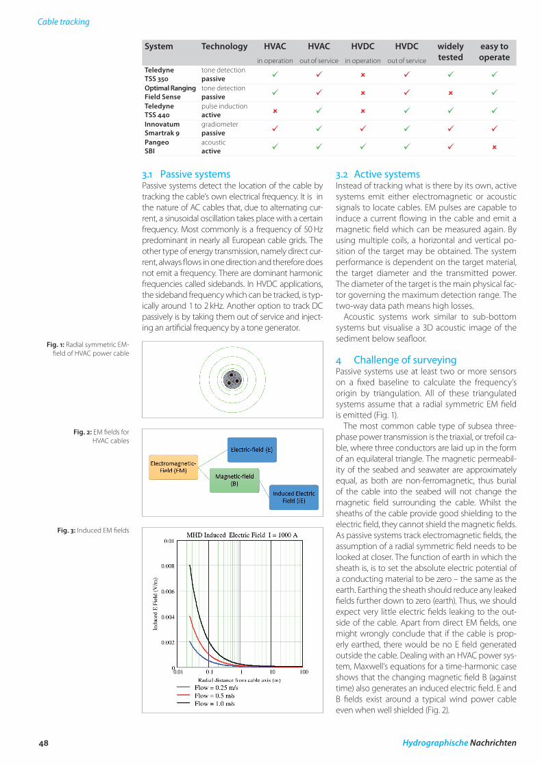
There are several technologies which may be used for the task of surveying, all of which have advantages and disadvantages (see table). The key task is to identi-fy which system is suitable to fulfil the task in a certain configuration. The cable tracking systems can be cat-egorised in either active or passive systems, meaning the procedure of how the systems detect the cables.
1 Subsea power cables There are many offshore constructions that need power cables to either supply energy or, more com-mon, deliver produced energy to the beach. The ever-growing renewables industry is building many wind farms. Many cables are laid in the vicinity of wind farms. There are two kinds of cables, inter-array and export cables. The inter-array cables connect the single windmills with the transformer station. The export cable transports the energy to shore.
Other fields where subsea power cables are used, are islands like Norderney or Heligoland that connect the islands to the mainland’s power grid. Further-more, countries are linked by power cables to level load and overproduction like Norway and Germany.
Subsea power cables can be anything from 70 mm to, exceeding, 210 mm in diameter and there exist two kinds: high voltage AC (alternating current), HVAC, and high voltage DC (direct current), HVDC. The selection criteria which type of cable to use, is heavily dependent on the route length, voltage and transmission capacity. When offshore wind developers decide between HVAC and HVDC cabling, the overall system must be taken into con-sideration – including cables and transformers/converters. There is a break-even distance between HVAC and HVDC, generally considered between 40 and 80 km, where economic reasons outweigh the building of a HVDC connection. AC cables are three-phase cables, and are laid either as a bundle in a three-core formation, or as three separate cables. The configuration of DC cables is dependent on the DC system. There are two main types: monopolar and bipolar. Generally speaking, they consist of two conductors, either laid separately, bundled together or in a coaxial arrangement.
In 1954 the world’s first subsea HVDC cable, Gotland 1, was installed. It was 98 km long, stretch-ing from Gotland Island to the Swedish Mainland and with a capacity of 20 MW. This changed the world’s view on submarine electricity transmission as it was realised that it was now possible to con-nect to other countries overseas that were previ-ously thought unreachable.
Currently, the longest interconnector is the NorNed cable between Norway and the Nether-
An article by OlIVEr ANDErS
AuthorOliver Anders works as a hydrographic surveyor at Fugro OSAE GmbH in Bremen.
The rising number of wind parks, and thus the demand for new survey tasks, results in continuous development for companies working in the renewable energy sector. Building a wind park requires laying inter-array and export cables. Those cables are buried or covered to protect them, bringing environmental changes to a minimum. A
common depth of buri-al ranges from 1.5 m to 3 m. The challenge of surveying those buried power cables is choos-ing the right method.
The challenge of choosing the right method for surveying power cables
cable tracking | depth of burial | HVAC/HVDC | survey power cables
48 Hydrographische Nachrichten
Cable tracking
3.2 Active systemsInstead of tracking what is there by its own, active systems emit either electromagnetic or acoustic signals to locate cables. EM pulses are capable to induce a current flowing in the cable and emit a magnetic field which can be measured again. By using multiple coils, a horizontal and vertical po-sition of the target may be obtained. The system performance is dependent on the target material, the target diameter and the transmitted power. The diameter of the target is the main physical fac-tor governing the maximum detection range. The two-way data path means high losses.
Acoustic systems work similar to sub-bottom systems but visualise a 3D acoustic image of the sediment below seafloor.
4 Challenge of surveyingPassive systems use at least two or more sensors on a fixed baseline to calculate the frequency’s origin by triangulation. All of these triangulated systems assume that a radial symmetric EM field is emitted (Fig. 1).
The most common cable type of subsea three-phase power transmission is the triaxial, or trefoil ca-ble, where three conductors are laid up in the form of an equilateral triangle. The magnetic permeabil-ity of the seabed and seawater are approximately equal, as both are non-ferromagnetic, thus burial of the cable into the seabed will not change the magnetic field surrounding the cable. Whilst the sheaths of the cable provide good shielding to the electric field, they cannot shield the magnetic fields. As passive systems track electromagnetic fields, the assumption of a radial symmetric field needs to be looked at closer. The function of earth in which the sheath is, is to set the absolute electric potential of a conducting material to be zero – the same as the earth. Earthing the sheath should reduce any leaked fields further down to zero (earth). Thus, we should expect very little electric fields leaking to the out-side of the cable. Apart from direct EM fields, one might wrongly conclude that if the cable is prop-erly earthed, there would be no E field generated outside the cable. Dealing with an HVAC power sys-tem, Maxwell’s equations for a time-harmonic case shows that the changing magnetic field B (against time) also generates an induced electric field. E and B fields exist around a typical wind power cable even when well shielded (Fig. 2).
3.1 Passive systemsPassive systems detect the location of the cable by tracking the cable’s own electrical frequency. It is in the nature of AC cables that, due to alternating cur-rent, a sinusoidal oscillation takes place with a certain frequency. Most commonly is a frequency of 50 Hz predominant in nearly all European cable grids. The other type of energy transmission, namely direct cur-rent, always flows in one direction and therefore does not emit a frequency. There are dominant harmonic frequencies called sidebands. In HVDC applications, the sideband frequency which can be tracked, is typ-ically around 1 to 2 kHz. Another option to track DC passively is by taking them out of service and inject-ing an artificial frequency by a tone generator.
System Technology HVACin operation
HVACout of service
HVDCin operation
HVDCout of service
widely tested
easy to operate
Teledyne TSS 350
tone detectionpassive
Optimal Ranging Field Sense
tone detectionpassive
Teledyne TSS 440
pulse inductionactive
Innovatum Smartrak 9
gradiometerpassive
Pangeo SBI
acousticactive
Fig. 1: Radial symmetric EM-field of HVAC power cable
Fig. 2: EM fields for HVAC cables
Fig. 3: Induced EM fields
HN 105 — 11/2016 49
Cable tracking
ment, are expensive and slow compared to multi-beam measurements. Once the cable is in a stable condition (no hardening, no heating-up phase) an indirect cable survey by multibeam sediment difference will give a quick and cheap depth of burial result. For a first initial primal measurement, the cable is located by one of the standard pipe and cable tracking systems. The results give a di-rect map of the absolute depth of the cable and its burial state. This data also contains absolute seabed height. At the stage of another survey ep-och a multibeam survey provides absolute seabed heights as well. By comparing the two multibeam depth information and considering the cable as stable, a change of the burial state can be derived. The aim is to provide quicker and cheaper infor-mation about the burial state of the cable. This combined cable tracking and multibeam seabed difference can be used to fulfil that aim. “
If this magnetic field is induced in flowing sea-water, then an electric field will be induced in the sea by magneto-hydrodynamic (MHD) generation (Fig. 3).
Many researches in EM field propagation around submarine cables were conducted during the last years with a special focus on environmental or mammal effects. These studies give a good insight of EM field propagation for submarine cables. Re-sults demonstrated that a variety of factors, such as topographic, bathymetric, and geologic con-ditions contribute to the natural generation and propagation of EM fields. Thus, a radial symmetric field can be distorted and result in wrong depth calculations (Fig. 4).
In case of a bipolar conductor the electromag-netic field is formed in an elliptical shape. If this is not corrected by postprocessing, wrong depth calculations are the result.
5 Indirect depth of burial survey by seabed differenceAs laid data gathered by the laying vessel is just valid for the time directly after cable lay, re-surveys are necessary at a later point of time to ensure a constant monitoring. The cable operator is inter-ested in the change of the burial depth. Cable surveys with cable trackers require special equip-
Fig. 4: Distorted radial symmetric EM-field trifoil and bipolar