Cabling of new homes for Telstra FTTP Information for builders and cabling providers TELSTRA CORPORATION LIMITED (ABN 33 051 775 556) | ISSUED 26/08/2013 ISSUE 8 – FINAL | TELSTRA UNRESTRICTED | DOCUMENT NO. 013234 | CABLING OF NEW HOMES FOR TELSTRA FTTP PAGE 1/29 Author’s name Business unit Telstra Operations Sub-business unit Access Technology Planning Issue date 26 August 2013 Issue number 8 Telstra ID 013234 Summary This document provides technical guidance to builders and telecommunications cabling providers for the installation of facilities for the supply of services to homes and small businesses via Telstra’s FTTP (Fibre To The Premises) network. This document is optimised for reading on a tablet or portable computer to take advantage of hyperlinks, document search functions and on-screen magnification of photographs and drawings. This publication has been prepared and written by Telstra Corporation Limited (ABN 33 051 775 556), and is copyright. Other than for the purposes of and subject to the conditions prescribed under the Copyright Act, no part of it may in any form or by any means (electronic, mechanical, microcopying, photocopying, recording or otherwise) be reproduced, stored in a retrieval system or transmitted without prior written permission from the document controller. Product or company names are trademarks or registered trademarks of their respective holders. Note for non-Telstra readers: The contents of this publication are subject to change without notice. All efforts have been made to ensure the accuracy of this publication. Notwithstanding, Telstra Corporation Limited does not assume responsibility for any errors nor for any consequences arising from any errors in this publication.
Transcript
Cabling of new homes for Telstra FTTP
Information for builders and cabling providers
TELSTRA CORPORATION LIMITED (ABN 33 051 775 556) | ISSUED 26/08/2013 ISSUE 8 – FINAL | TELSTRA UNRESTRICTED | DOCUMENT NO. 013234 | CABLING OF NEW HOMES FOR TELSTRA FTTP
PAGE 1/29
Author’s name
Business unit
Telstra Operations
Sub-business unit
Access Technology Planning
Issue date
26 August 2013
Issue number
8
Telstra ID
013234
Summary
This document provides technical guidance to builders and telecommunications cabling providers for the
installation of facilities for the supply of services to homes and small businesses via Telstra’s FTTP
(Fibre To The Premises) network.
This document is optimised for reading on a tablet or portable computer to take advantage of hyperlinks,
document search functions and on-screen magnification of photographs and drawings.
This publication has been prepared and written by Telstra Corporation Limited (ABN 33 051 775 556), and is copyright. Other than for the purposes of and subject to the conditions prescribed under the Copyright Act, no part of it may in any form or by any means (electronic, mechanical, microcopying, photocopying, recording or otherwise) be reproduced, stored in a retrieval system or transmitted without prior written permission from the document controller. Product or company names are trademarks or registered trademarks of their respective holders.
Note for non-Telstra readers: The contents of this publication are subject to change without notice. All efforts have been made to ensure the accuracy of this publication. Notwithstanding, Telstra Corporation Limited does not assume responsibility for any errors nor for any consequences arising from any errors in this publication.
Cabling of new homes for Telstra FTTP
Information for builders and cabling providers
TELSTRA CORPORATION LIMITED (ABN 33 051 775 556) | ISSUED 26/08/2013 ISSUE 8 – FINAL | TELSTRA UNRESTRICTED | DOCUMENT NO. 013234 | CABLING OF NEW HOMES FOR TELSTRA FTTP
3.1 What is FTTP? ........................................................................................................................ 3 3.2 What services does Telstra FTTP provide? ........................................................................... 3 3.3 FTTP equipment ..................................................................................................................... 4
3.3.1 General.................................................................................................................... 4 3.3.2 Network Termination Device (NTD) and Power Supply Unit (PSU) ..................... 4 3.3.3 Premises Connection Device (PCD) ...................................................................... 4 3.3.4 Fibre Wall Outlet (FWO) ......................................................................................... 4 3.3.5 Power point ............................................................................................................. 4 3.3.6 Telstra FTTP equipment connection arrangements .............................................. 7
4 LOCATION OF THE FTTP EQUIPMENT ........................................................................................ 8 4.1 General .................................................................................................................................... 8 4.2 NTD and PSU location factors ............................................................................................... 8
5 CABLING OF THE HOME TO SUPPORT FTTP ........................................................................... 11 5.1 Things have changed ........................................................................................................... 11 5.2 Home cabling ........................................................................................................................ 11 5.3 Limitations ............................................................................................................................. 11 5.4 Further information ................................................................................................................ 11 5.5 Coaxial cabling (where required) ......................................................................................... 13
TELSTRA CORPORATION LIMITED (ABN 33 051 775 556) | ISSUED 26/08/2013 ISSUE 8 – FINAL | TELSTRA UNRESTRICTED | DOCUMENT NO. 013234 | CABLING OF NEW HOMES FOR TELSTRA FTTP
PAGE 3/29
1 PURPOSE
This document sets out Telstra’s requirements for the connection of services using Telstra’s FTTP (Fibre
To The Premises) network including Telstra Velocity®.
This Document and associated documents may be accessed under the “Builders” menu of the Telstra
Smart Community® website at http://www.telstra.com.au/smart-community/builders/.
2 SCOPE
This document applies to any building to be constructed for use as a home or to conduct a small
business (note that some business services are not supported by Telstra FTTP). It applies to detached
buildings (single dwellings) as well as semi-detached buildings (town houses, villas, etc.).
Additional guidelines for cabling of multi-storey, multiple-dwelling units (MDUs) are provided in Telstra
Document No. 013234a05, Information summary for property developers — Cabling of multi-storey units
(“apartments”) for Telstra Velocity®.
3 INTRODUCTION
3.1 What is FTTP?
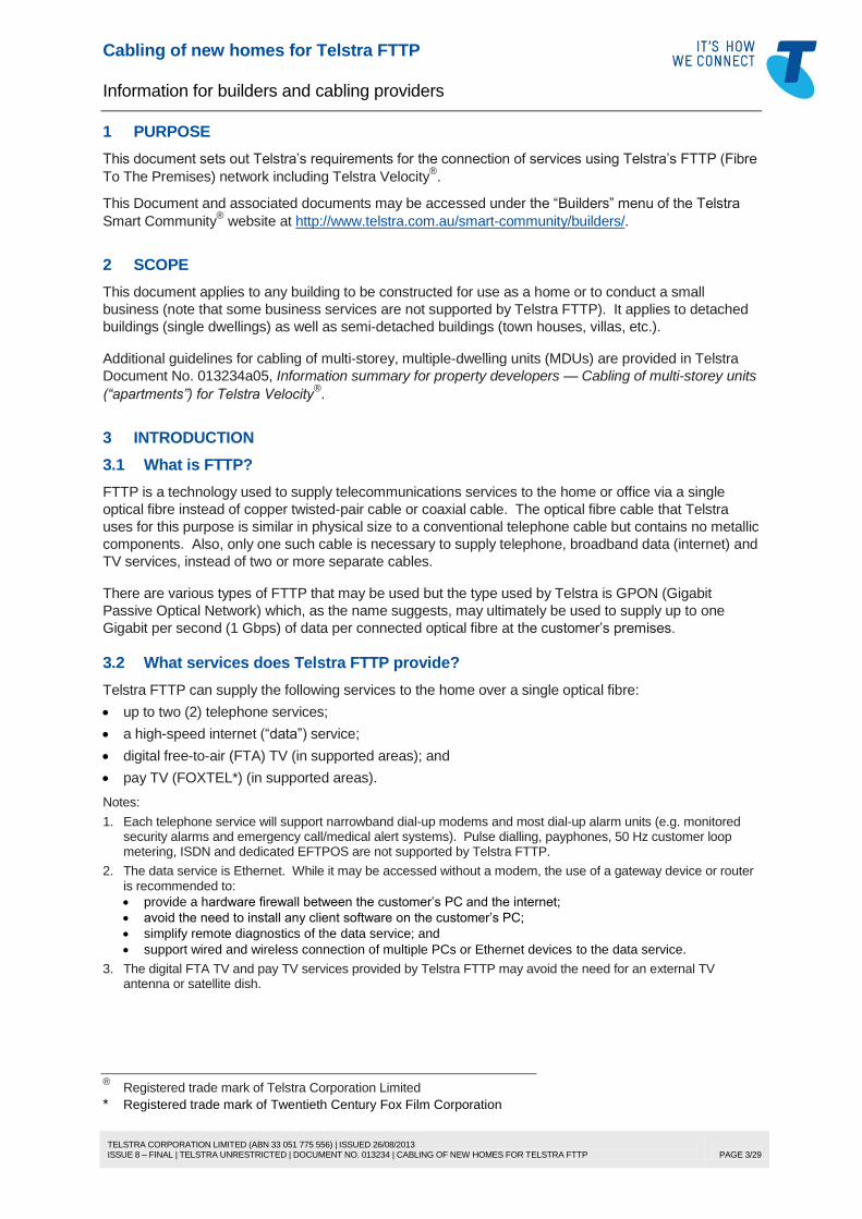
FTTP is a technology used to supply telecommunications services to the home or office via a single
optical fibre instead of copper twisted-pair cable or coaxial cable. The optical fibre cable that Telstra
uses for this purpose is similar in physical size to a conventional telephone cable but contains no metallic
components. Also, only one such cable is necessary to supply telephone, broadband data (internet) and
TV services, instead of two or more separate cables.
There are various types of FTTP that may be used but the type used by Telstra is GPON (Gigabit
Passive Optical Network) which, as the name suggests, may ultimately be used to supply up to one
Gigabit per second (1 Gbps) of data per connected optical fibre at the customer’s premises.
3.2 What services does Telstra FTTP provide?
Telstra FTTP can supply the following services to the home over a single optical fibre:
up to two (2) telephone services;
a high-speed internet (“data”) service;
digital free-to-air (FTA) TV (in supported areas); and
pay TV (FOXTEL*) (in supported areas).
Notes:
1. Each telephone service will support narrowband dial-up modems and most dial-up alarm units (e.g. monitored security alarms and emergency call/medical alert systems). Pulse dialling, payphones, 50 Hz customer loop metering, ISDN and dedicated EFTPOS are not supported by Telstra FTTP.
2. The data service is Ethernet. While it may be accessed without a modem, the use of a gateway device or router is recommended to:
provide a hardware firewall between the customer’s PC and the internet;
avoid the need to install any client software on the customer’s PC;
simplify remote diagnostics of the data service; and
support wired and wireless connection of multiple PCs or Ethernet devices to the data service.
3. The digital FTA TV and pay TV services provided by Telstra FTTP may avoid the need for an external TV antenna or satellite dish.
® Registered trade mark of Telstra Corporation Limited
* Registered trade mark of Twentieth Century Fox Film Corporation
TELSTRA CORPORATION LIMITED (ABN 33 051 775 556) | ISSUED 26/08/2013 ISSUE 8 – FINAL | TELSTRA UNRESTRICTED | DOCUMENT NO. 013234 | CABLING OF NEW HOMES FOR TELSTRA FTTP
PAGE 4/29
3.3 FTTP equipment
3.3.1 General
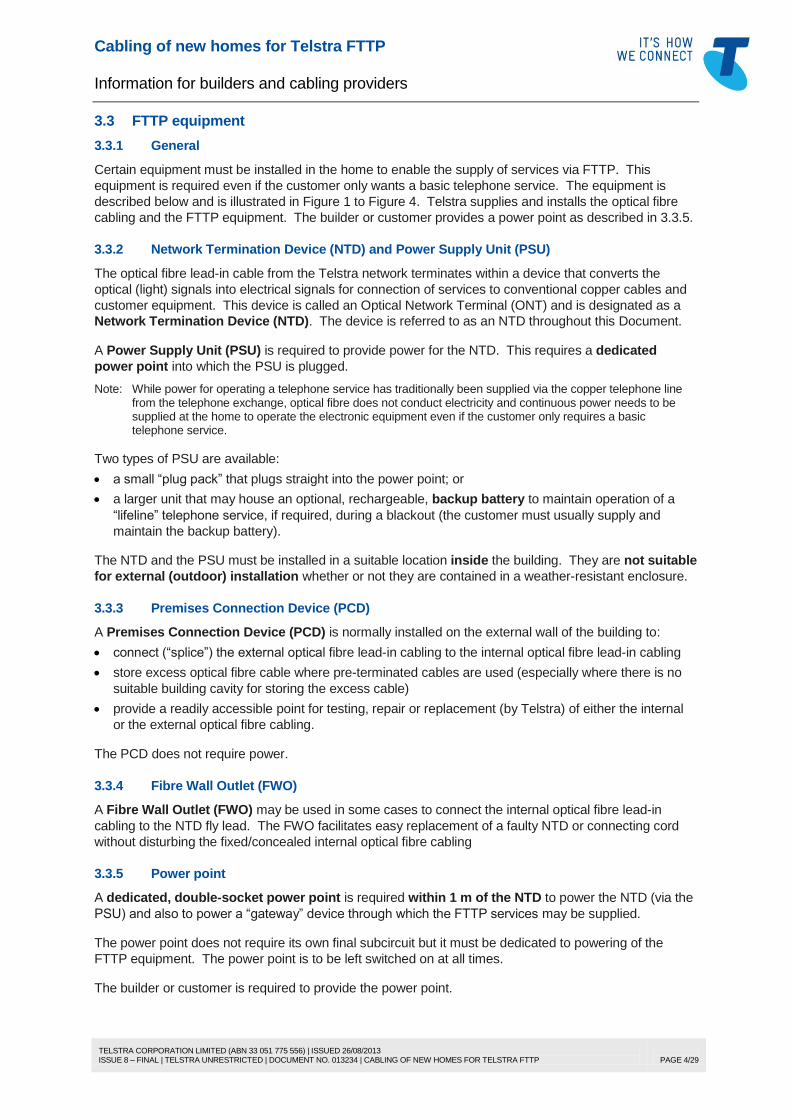
Certain equipment must be installed in the home to enable the supply of services via FTTP. This
equipment is required even if the customer only wants a basic telephone service. The equipment is
described below and is illustrated in Figure 1 to Figure 4. Telstra supplies and installs the optical fibre
cabling and the FTTP equipment. The builder or customer provides a power point as described in 3.3.5.
3.3.2 Network Termination Device (NTD) and Power Supply Unit (PSU)
The optical fibre lead-in cable from the Telstra network terminates within a device that converts the
optical (light) signals into electrical signals for connection of services to conventional copper cables and
customer equipment. This device is called an Optical Network Terminal (ONT) and is designated as a
Network Termination Device (NTD). The device is referred to as an NTD throughout this Document.
A Power Supply Unit (PSU) is required to provide power for the NTD. This requires a dedicated
power point into which the PSU is plugged.
Note: While power for operating a telephone service has traditionally been supplied via the copper telephone line from the telephone exchange, optical fibre does not conduct electricity and continuous power needs to be supplied at the home to operate the electronic equipment even if the customer only requires a basic telephone service.
Two types of PSU are available:
a small “plug pack” that plugs straight into the power point; or
a larger unit that may house an optional, rechargeable, backup battery to maintain operation of a
“lifeline” telephone service, if required, during a blackout (the customer must usually supply and
maintain the backup battery).
The NTD and the PSU must be installed in a suitable location inside the building. They are not suitable
for external (outdoor) installation whether or not they are contained in a weather-resistant enclosure.
3.3.3 Premises Connection Device (PCD)
A Premises Connection Device (PCD) is normally installed on the external wall of the building to:
connect (“splice”) the external optical fibre lead-in cabling to the internal optical fibre lead-in cabling
store excess optical fibre cable where pre-terminated cables are used (especially where there is no
suitable building cavity for storing the excess cable)
provide a readily accessible point for testing, repair or replacement (by Telstra) of either the internal
or the external optical fibre cabling.
The PCD does not require power.
3.3.4 Fibre Wall Outlet (FWO)
A Fibre Wall Outlet (FWO) may be used in some cases to connect the internal optical fibre lead-in
cabling to the NTD fly lead. The FWO facilitates easy replacement of a faulty NTD or connecting cord
without disturbing the fixed/concealed internal optical fibre cabling
3.3.5 Power point
A dedicated, double-socket power point is required within 1 m of the NTD to power the NTD (via the
PSU) and also to power a “gateway” device through which the FTTP services may be supplied.
The power point does not require its own final subcircuit but it must be dedicated to powering of the
FTTP equipment. The power point is to be left switched on at all times.
The builder or customer is required to provide the power point.
Cabling of new homes for Telstra FTTP
Information for builders and cabling providers
TELSTRA CORPORATION LIMITED (ABN 33 051 775 556) | ISSUED 26/08/2013 ISSUE 8 – FINAL | TELSTRA UNRESTRICTED | DOCUMENT NO. 013234 | CABLING OF NEW HOMES FOR TELSTRA FTTP
PAGE 5/29
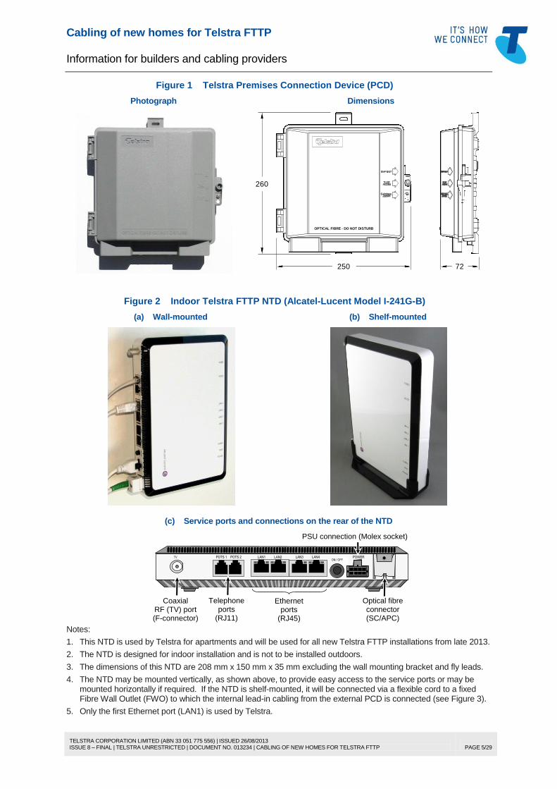
Figure 1 Telstra Premises Connection Device (PCD)
Photograph Dimensions
72250
260
OPTICAL FIBRE - DO NOT DISTURB
Figure 2 Indoor Telstra FTTP NTD (Alcatel-Lucent Model I-241G-B)
(a) Wall-mounted (b) Shelf-mounted
(c) Service ports and connections on the rear of the NTD
Coaxial RF (TV) port (F-connector)
Telephone ports
(RJ11)
Ethernet ports
(RJ45)
PSU connection (Molex socket)
Optical fibre connector (SC/APC)
TV POTS 1 POTS 2 LAN1 LAN2 LAN3 LAN4 POWER ON / OFF
Notes:
1. This NTD is used by Telstra for apartments and will be used for all new Telstra FTTP installations from late 2013.
2. The NTD is designed for indoor installation and is not to be installed outdoors.
3. The dimensions of this NTD are 208 mm x 150 mm x 35 mm excluding the wall mounting bracket and fly leads.
4. The NTD may be mounted vertically, as shown above, to provide easy access to the service ports or may be mounted horizontally if required. If the NTD is shelf-mounted, it will be connected via a flexible cord to a fixed Fibre Wall Outlet (FWO) to which the internal lead-in cabling from the external PCD is connected (see Figure 3).
5. Only the first Ethernet port (LAN1) is used by Telstra.
Cabling of new homes for Telstra FTTP
Information for builders and cabling providers
TELSTRA CORPORATION LIMITED (ABN 33 051 775 556) | ISSUED 26/08/2013 ISSUE 8 – FINAL | TELSTRA UNRESTRICTED | DOCUMENT NO. 013234 | CABLING OF NEW HOMES FOR TELSTRA FTTP
PAGE 6/29
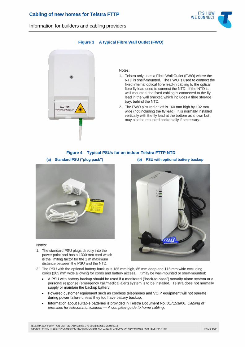
Figure 3 A typical Fibre Wall Outlet (FWO)
Notes:
1. Telstra only uses a Fibre Wall Outlet (FWO) where the NTD is shelf-mounted. The FWO is used to connect the fixed internal optical fibre lead-in cabling to the optical fibre fly lead used to connect the NTD. If the NTD is wall-mounted, the fixed cabling is connected to the fly lead in the wall bracket, which includes a fibre storage tray, behind the NTD.
2. The FWO pictured at left is 160 mm high by 102 mm wide (not including the fly lead). It is normally installed vertically with the fly lead at the bottom as shown but may also be mounted horizontally if necessary.
Figure 4 Typical PSUs for an indoor Telstra FTTP NTD
(a) Standard PSU (“plug pack”) (b) PSU with optional battery backup
Notes:
1. The standard PSU plugs directly into the power point and has a 1300 mm cord which is the limiting factor for the 1 m maximum distance between the PSU and the NTD.
2. The PSU with the optional battery backup is 185 mm high, 85 mm deep and 115 mm wide excluding cords (205 mm wide allowing for cords and battery access). It may be wall-mounted or shelf-mounted:
A PSU with battery backup should be used if a monitored (“back-to-base”) security alarm system or a personal response (emergency call/medical alert) system is to be installed. Telstra does not normally supply or maintain the backup battery.
Powered customer equipment such as cordless telephones and VOIP equipment will not operate during power failure unless they too have battery backup.
Information about suitable batteries is provided in Telstra Document No. 017153a00, Cabling of premises for telecommunications — A complete guide to home cabling.
Cabling of new homes for Telstra FTTP
Information for builders and cabling providers
TELSTRA CORPORATION LIMITED (ABN 33 051 775 556) | ISSUED 26/08/2013 ISSUE 8 – FINAL | TELSTRA UNRESTRICTED | DOCUMENT NO. 013234 | CABLING OF NEW HOMES FOR TELSTRA FTTP
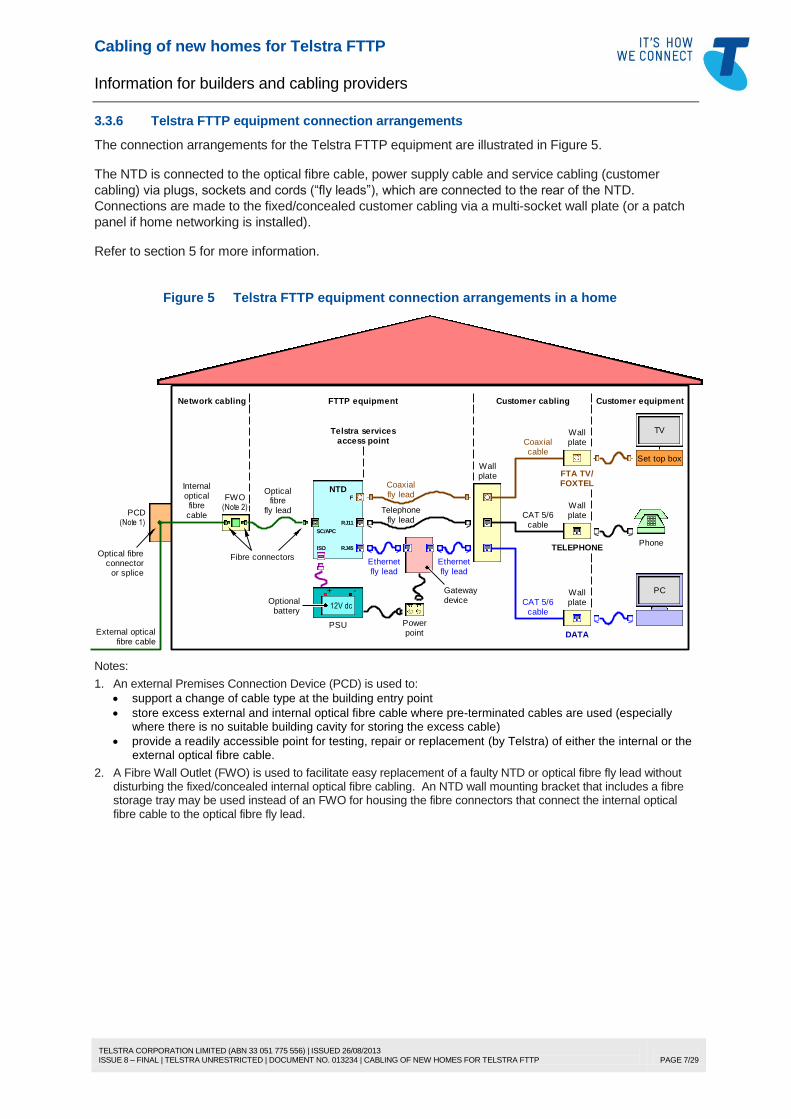
1. An external Premises Connection Device (PCD) is used to:
support a change of cable type at the building entry point
store excess external and internal optical fibre cable where pre-terminated cables are used (especially where there is no suitable building cavity for storing the excess cable)
provide a readily accessible point for testing, repair or replacement (by Telstra) of either the internal or the external optical fibre cable.
2. A Fibre Wall Outlet (FWO) is used to facilitate easy replacement of a faulty NTD or optical fibre fly lead without disturbing the fixed/concealed internal optical fibre cabling. An NTD wall mounting bracket that includes a fibre storage tray may be used instead of an FWO for housing the fibre connectors that connect the internal optical fibre cable to the optical fibre fly lead.
Cabling of new homes for Telstra FTTP
Information for builders and cabling providers
TELSTRA CORPORATION LIMITED (ABN 33 051 775 556) | ISSUED 26/08/2013 ISSUE 8 – FINAL | TELSTRA UNRESTRICTED | DOCUMENT NO. 013234 | CABLING OF NEW HOMES FOR TELSTRA FTTP
PAGE 8/29
4 LOCATION OF THE FTTP EQUIPMENT
4.1 General
All FTTP equipment needs to be readily accessible, i.e. capable of being reached easily and without
climbing over or removing obstructions, mounting upon a chair, or using a moveable ladder. It is
particularly important for optical fibre equipment to be accessible at ground/floor level because optical
fibre splicing and testing equipment is bulky and is not generally safe or suitable to use on a ladder.
Guidelines for location of the external Premises Connection Device (PCD) are provided in Telstra
Document No. 017153a02, Cabling of premises for telecommunications — Lead-in cabling and building
entry facilities for homes.
General guidance for the location of indoor electronic (powered) equipment is provided in Telstra
Document No. 017153a00. Specific guidance for locating a Telstra FTTP NTD and associated PSU is
provided in 4.2 below. The FTTP NTD and PSU are Telstra-owned network equipment which must be
located in accordance with 4.2. Telstra may refuse to install its equipment in a location that is unsuitable.
For a summary of suitable and unsuitable locations for the NTD and PSU, refer to Table 1.
4.2 NTD and PSU location factors
4.2.1 Heat
The NTD and PSU generate heat that must be dissipated to prevent overheating that may lead to
equipment failure or damage to the customer’s property. Adequate clearance must be maintained
around the equipment to ensure adequate ventilation. The equipment must not be installed behind
clothes in a robe, inside a linen closet or behind a window curtain (see 4.2.2).
The NTD and PSU must not be exposed to external heat sources that may raise the ambient
temperature to the extent that normal equipment ventilation will be inadequate to prevent overheating.
For example, the equipment must not be installed near a heating appliance or heating vent, be exposed
to direct sunlight (e.g. through a window) or be installed in an enclosure that is exposed to direct sunlight.
4.2.2 Lint and dust
The equipment must be installed in a lint-free environment to avoid a build-up of particles that may
impede the circulation of air around the internal components. Dusty environments must also be avoided.
The equipment must not be located behind any curtains. Curtains may shed lint or other fabric particles
onto the equipment. Rain is also a concern under windows (see 4.2.3). Curtains may also reduce
normal ventilation of the equipment (see 4.2.1).
4.2.3 Moisture
The equipment must not be located in any area of the home that may be moist from time to time, such
as a bathroom or laundry. While a domestic toilet (WC) is not usually a moist environment, the location
of the equipment in a toilet is not permitted due to limited space and access restrictions (obstacles).
The equipment must not be located under a window where it could be accidentally exposed to rain
ingress. The equipment must not be permanently exposed to open air (e.g. in an open patio, veranda or
car port) or within an external enclosure that is exposed to open air (heat is also a concern in such cases
— refer to 4.2.1).
4.2.4 Electromagnetic interference (EMI)
Certain appliances in the home may have the propensity to interfere with the proper functioning of the
FTTP equipment due to electromagnetic radiation (e.g. caused by power switching transients). Some
possible sources of interference are airconditioning units, refrigerators/freezers, ducted vacuum system
motors, fluorescent lamps, electric ovens/cooktops, electrical switchboards, etc.
The FTTP equipment should not be located within 1 m of any electrical equipment similar to those
described above, which may be a source of EMI.
Cabling of new homes for Telstra FTTP
Information for builders and cabling providers
TELSTRA CORPORATION LIMITED (ABN 33 051 775 556) | ISSUED 26/08/2013 ISSUE 8 – FINAL | TELSTRA UNRESTRICTED | DOCUMENT NO. 013234 | CABLING OF NEW HOMES FOR TELSTRA FTTP
PAGE 9/29
4.2.5 Access
4.2.5.1 General
The customer will be required to access the NTD and PSU regularly to monitor the visual indicators and
may also be required to test the services at the NTD service ports from time to time. Therefore, the NTD
and PSU must be readily accessible by the customer, i.e. the customer should not be required to stand
on a stool or a chair or lay on the floor to check the visible indicators or access the NTD service ports.
At least 900 mm x 900 mm clear floor space should be available in front of the equipment for access
purposes. Furniture or other objects that can be safely and easily moved by one person may be placed
in front of the equipment.
4.2.5.2 NTD
Sufficient space must be provided to access the NTD ports and to slide the NTD off the wall-mounting
bracket (where the NTD is wall-mounted).
Where the NTD is wall-mounted in a cupboard/closet/cabinet or beside a solid object (e.g. in a corner),
at least 90 mm clearance is required for connection of fly leads to the service port side of the NTD and at
least 25 mm clearance is required on all other sides of the NTD. Refer to the NTD clearance diagrams
in Table 1.
The NTD must be installed no less than 350 mm (measured to the bottom of the NTD) and no more than
1800 mm (measured to the top of the NTD) from floor level.
4.2.5.3 PSU
Where a PSU with battery backup is to be installed, sufficient clearance must be provided to see the
status LEDs and their symbols, to slide the PSU off the wall (if applicable) and to access the battery
compartment. If the PSU is fixed (i.e. wall-mounted) in the corner of a room or cupboard/closet/cabinet,
a minimum clearance of 250 mm must be provided to the left of the PSU so the customer can see the
LED symbols. At least 90 mm must be provided to the right of the PSU to fit or replace the battery.
Refer to the PSU clearance diagram in Table 1.
The PSU must be installed no more than 1800 mm from floor level (measured to the top of the PSU).
4.2.6 Equipment enclosure
If the FTTP equipment is to be housed in an (indoor) enclosure, refer to Telstra Document No.
017153a01, Cabling of premises for telecommunications — Essential information for home cabling, for
the enclosure requirements.
The enclosure must be adequately sized and ventilated and should not be recessed into the cavity of an
external (perimeter) wall. The cavity of an external wall may be damp, which means the inside of the
enclosure may be damp, and this may lead to corrosion of the equipment. Heat build-up may also be an
issue with external walls exposed to the sun during the summer (see 4.2.1).
Note: The enclosure may be installed on the surface of the internal wall. However, the cable entry holes to the wall cavity should be stopped to minimise the entry of humid air and debris from the cavity to the enclosure.
Cabling of new homes for Telstra FTTP
Information for builders and cabling providers
TELSTRA CORPORATION LIMITED (ABN 33 051 775 556) | ISSUED 26/08/2013 ISSUE 8 – FINAL | TELSTRA UNRESTRICTED | DOCUMENT NO. 013234 | CABLING OF NEW HOMES FOR TELSTRA FTTP
PAGE 10/29
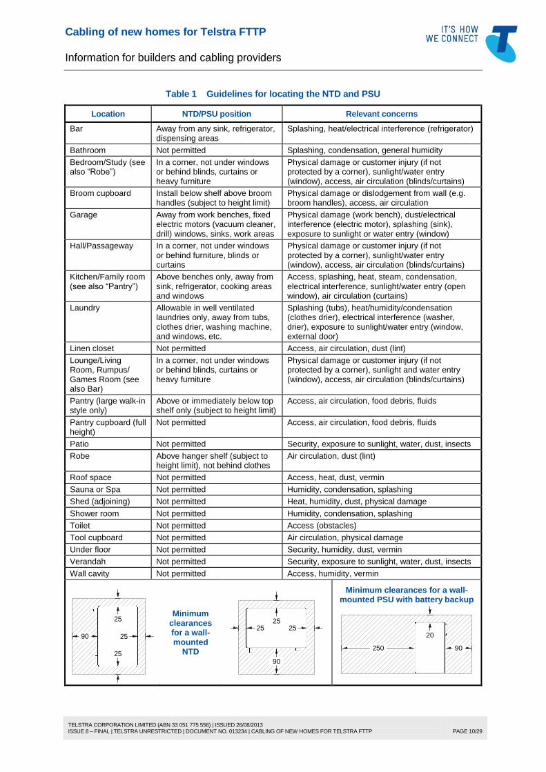
Table 1 Guidelines for locating the NTD and PSU
Location NTD/PSU position Relevant concerns
Bar Away from any sink, refrigerator, dispensing areas
Linen closet Not permitted Access, air circulation, dust (lint)
Lounge/Living Room, Rumpus/ Games Room (see also Bar)
In a corner, not under windows or behind blinds, curtains or heavy furniture
Physical damage or customer injury (if not protected by a corner), sunlight and water entry (window), access, air circulation (blinds/curtains)
Pantry (large walk-in style only)
Above or immediately below top shelf only (subject to height limit)
Access, air circulation, food debris, fluids
Pantry cupboard (full height)
Not permitted Access, air circulation, food debris, fluids
Patio Not permitted Security, exposure to sunlight, water, dust, insects
Robe Above hanger shelf (subject to height limit), not behind clothes
Air circulation, dust (lint)
Roof space Not permitted Access, heat, dust, vermin
Sauna or Spa Not permitted Humidity, condensation, splashing
Shed (adjoining) Not permitted Heat, humidity, dust, physical damage
Shower room Not permitted Humidity, condensation, splashing
Toilet Not permitted Access (obstacles)
Tool cupboard Not permitted Air circulation, physical damage
Under floor Not permitted Security, humidity, dust, vermin
Verandah Not permitted Security, exposure to sunlight, water, dust, insects
Wall cavity Not permitted Access, humidity, vermin
90
25
25
25
Minimum clearances for a wall-mounted
NTD
25
90
25 25
Minimum clearances for a wall-mounted PSU with battery backup
20
90250
Cabling of new homes for Telstra FTTP
Information for builders and cabling providers
TELSTRA CORPORATION LIMITED (ABN 33 051 775 556) | ISSUED 26/08/2013 ISSUE 8 – FINAL | TELSTRA UNRESTRICTED | DOCUMENT NO. 013234 | CABLING OF NEW HOMES FOR TELSTRA FTTP
PAGE 11/29
5 CABLING OF THE HOME TO SUPPORT FTTP
5.1 Things have changed
Traditionally, telephone and ADSL access points (outlets) have been wired sequentially from an external
wall box or radially from an outdoor NTD. These cabling methods are unsuitable for new homes as
they will not support modern telecommunications services, especially services supplied via Telstra FTTP
or the National Broadband Network (NBN).
In the past, Telstra has used an outdoor FTTP NTD for houses. From late 2013, Telstra will be using
an indoor FTTP NTD, which is consistent with the FTTP arrangements used with the NBN. The outdoor
Telstra FTTP NTD is now regarded as “legacy” equipment and is described in section 6 for maintenance
purposes only.
The FTTP equipment connection arrangements for Telstra FTTP are illustrated in Figure 5 (page 7).
The home cabling architecture required to support FTTP is described in 5.2.
5.2 Home cabling
The cabling architecture required to support Telstra (and NBN) FTTP is illustrated in Figure 6.
The optical fibre cables and equipment are too fragile to be installed during construction and must be
installed by the carrier (Telstra) after the building is completed. Therefore, the builder is required to
install suitable conduit (with pull cord) or trunking during construction to enable the optical fibre cables to
be pulled in and the FTTP equipment installed without the need to access roof or underfloor spaces.
5.3 Limitations
The Telstra FTTP NTD and PSU must be located in the same building where the services will be used
by the end-user. For technical and safety reasons, the NTD cannot be located at a detached
structure such as a fence or a separate garage.
The Telstra FTTP NTD service ports must not be connected to any metallic-conductor cable that runs to
another building except as described in section 12 of Telstra Document No. 017153a00.
The maximum length of internal cabling that may be connected to a telephone port of the Telstra NTD is
300 metres (e.g. for connection to a lift telephone in multi-storey residential apartments). This assumes
the use of cable with 0.50 mm diameter (24 AWG) solid copper conductors.
5.4 Further information
For more information about cabling a home for FTTP, refer to the following Telstra guidelines:
Document No. 017153a00, Cabling of premises for telecommunications — A complete guide to home
cabling (a comprehensive reference, including tutorials, customer cabling options, CCP wiring, data
cable installation practices, coaxial cabling guidelines and backup battery information)
Document No. 017153a01, Cabling of premises for telecommunications — Essential information for
home cabling (basic guidance for cabling a new home)
Document No. 017153a02, Cabling of premises for telecommunications — Lead-in cabling and
building entry facilities for homes (detailed guidance about providing facilities for installation of the
cabling between the access pit and the indoor FTTP NTD).
Cabling of new homes for Telstra FTTP
Information for builders and cabling providers
TELSTRA CORPORATION LIMITED (ABN 33 051 775 556) | ISSUED 26/08/2013 ISSUE 8 – FINAL | TELSTRA UNRESTRICTED | DOCUMENT NO. 013234 | CABLING OF NEW HOMES FOR TELSTRA FTTP
PAGE 12/29
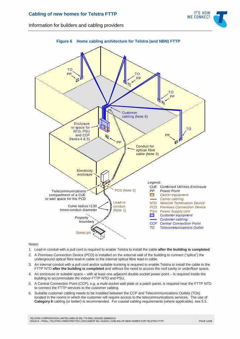
Figure 6 Home cabling architecture for Telstra (and NBN) FTTP
TO
TO
PP
PP
Conduit foroptical fibre
Lead-inconduit
cable (Note 3)
Electricityenclosure
Street pit
(Note 1)
Curve radius >130times conduit diameter
PP Power Point
Legend:
PCD Premises Connection Device
Carrier equipment
TO Telecommunications Outlet
Customer cabling
CCP Central Connection Point
Customer equipment
Carrier cabling
Propertyboundary
Telecommunicationscompartment of a CUE
or wall space for the PCD
TO
PP
TO
PP
PP
Enclosureor space for
NTD, PSUand CCP
PCD (Note 2)
(Notes 4 & 5)
Customercabling (Note 6)
CUE Combined Util i ties Enclosure
NTD Network Termination Device
PSU Power Supply Unit
Notes:
1. Lead-in conduit with a pull cord is required to enable Telstra to install the cable after the building is completed.
2. A Premises Connection Device (PCD) is installed on the external wall of the building to connect (“splice”) the underground optical fibre lead-in cable to the internal optical fibre lead-in cable.
3. An internal conduit with a pull cord and/or suitable trunking is required to enable Telstra to install the cable to the FTTP NTD after the building is completed and without the need to access the roof cavity or underfloor space.
4. An enclosure or suitable space – with at least one adjacent double-socket power point – is required inside the building to accommodate the indoor FTTP NTD and PSU.
5. A Central Connection Point (CCP), e.g. a multi-socket wall plate or a patch panel, is required near the FTTP NTD to connect the FTTP services to the customer cabling.
6. Suitable customer cabling needs to be installed between the CCP and Telecommunications Outlets (TOs) located in the rooms in which the customer will require access to the telecommunications services. The use of Category 6 cabling (or better) is recommended. For coaxial cabling requirements (where applicable), see 5.5.
Cabling of new homes for Telstra FTTP
Information for builders and cabling providers
TELSTRA CORPORATION LIMITED (ABN 33 051 775 556) | ISSUED 26/08/2013 ISSUE 8 – FINAL | TELSTRA UNRESTRICTED | DOCUMENT NO. 013234 | CABLING OF NEW HOMES FOR TELSTRA FTTP
PAGE 13/29
5.5 Coaxial cabling (where required)
Some Telstra FTTP networks provide access to digital free-to-air (FTA) TV and/or FOXTEL via a single
radio frequency (RF) port on the NTD. This is provided in some developments to avoid the need for
external TV antennas and satellite dishes.
Coaxial cabling guidelines are provided in Telstra Document No. 017153a00 and may be applied to
coaxial cabling connected to a Telstra FTTP NTD. For calculation of losses for the purpose of designing
the coaxial cabling system as described in Document No. 017153a00, the expected RF signal levels at
the F-connector of the FTTP NTD are provided in Table 2.
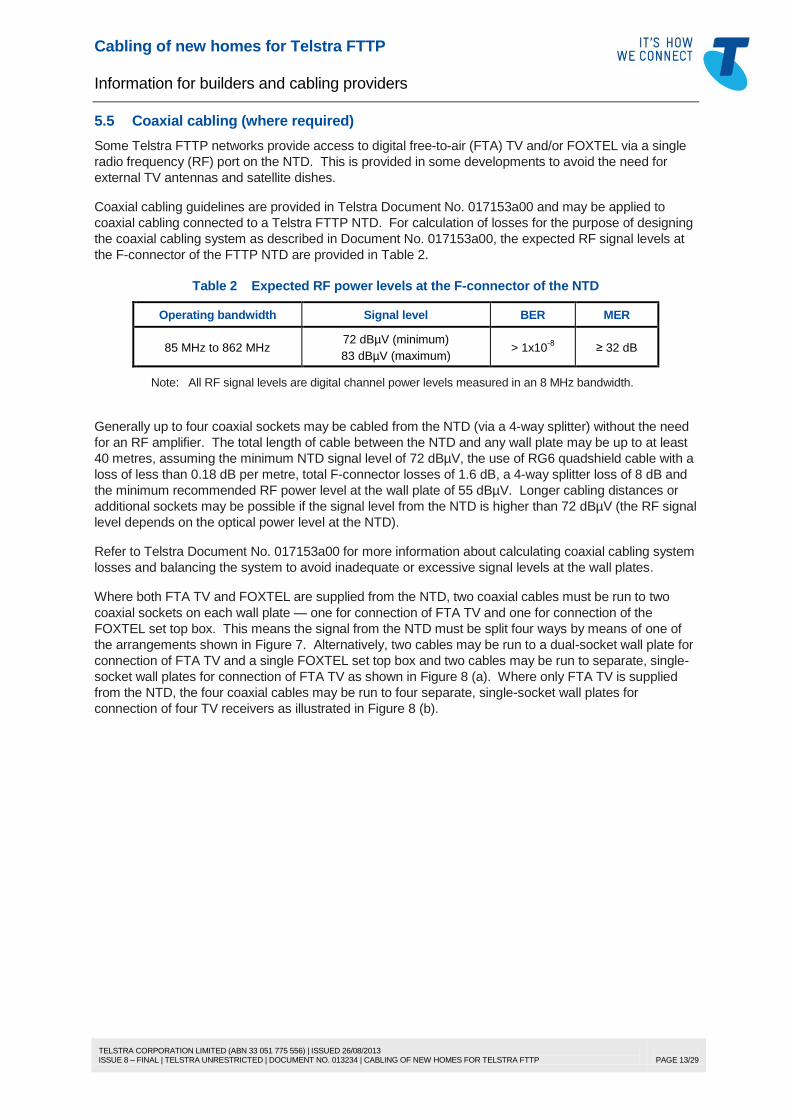
Table 2 Expected RF power levels at the F-connector of the NTD
Operating bandwidth Signal level BER MER
85 MHz to 862 MHz 72 dBµV (minimum)
83 dBµV (maximum) > 1x10
-8 ≥ 32 dB
Note: All RF signal levels are digital channel power levels measured in an 8 MHz bandwidth.
Generally up to four coaxial sockets may be cabled from the NTD (via a 4-way splitter) without the need
for an RF amplifier. The total length of cable between the NTD and any wall plate may be up to at least
40 metres, assuming the minimum NTD signal level of 72 dBµV, the use of RG6 quadshield cable with a
loss of less than 0.18 dB per metre, total F-connector losses of 1.6 dB, a 4-way splitter loss of 8 dB and
the minimum recommended RF power level at the wall plate of 55 dBµV. Longer cabling distances or
additional sockets may be possible if the signal level from the NTD is higher than 72 dBµV (the RF signal
level depends on the optical power level at the NTD).
Refer to Telstra Document No. 017153a00 for more information about calculating coaxial cabling system
losses and balancing the system to avoid inadequate or excessive signal levels at the wall plates.
Where both FTA TV and FOXTEL are supplied from the NTD, two coaxial cables must be run to two
coaxial sockets on each wall plate — one for connection of FTA TV and one for connection of the
FOXTEL set top box. This means the signal from the NTD must be split four ways by means of one of
the arrangements shown in Figure 7. Alternatively, two cables may be run to a dual-socket wall plate for
connection of FTA TV and a single FOXTEL set top box and two cables may be run to separate, single-
socket wall plates for connection of FTA TV as shown in Figure 8 (a). Where only FTA TV is supplied
from the NTD, the four coaxial cables may be run to four separate, single-socket wall plates for
connection of four TV receivers as illustrated in Figure 8 (b).
Cabling of new homes for Telstra FTTP
Information for builders and cabling providers
TELSTRA CORPORATION LIMITED (ABN 33 051 775 556) | ISSUED 26/08/2013 ISSUE 8 – FINAL | TELSTRA UNRESTRICTED | DOCUMENT NO. 013234 | CABLING OF NEW HOMES FOR TELSTRA FTTP
PAGE 14/29
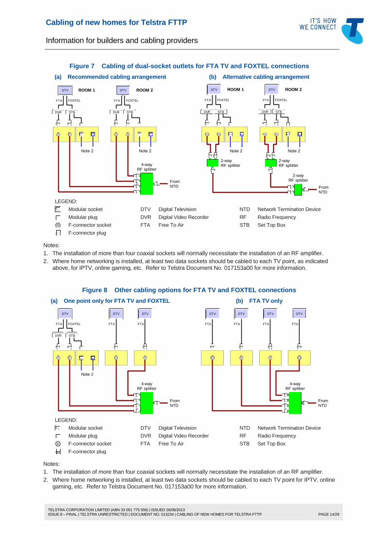
Figure 7 Cabling of dual-socket outlets for FTA TV and FOXTEL connections
(a) Recommended cabling arrangement (b) Alternative cabling arrangement
ROOM 1 ROOM 2
FOXTEL
DVR STB
FTA FOXTEL
DVR STB
FTA
RF splitter4-way
NTDFrom
DTV DTV
Note 2 Note 2
RF splitter2-way
RF splitter2-way
RF splitter2-way
NTDFrom
ROOM 1 ROOM 2
FOXTEL
DVR STB
FTA FOXTEL
DVR STB
FTA
DTV DTV
Note 2 Note 2
LEGEND:
Modular socket DTV Digital Television NTD Network Termination Device
Modular plug DVR Digital Video Recorder RF Radio Frequency
F-connector socket FTA Free To Air STB Set Top Box
F-connector plug
Notes:
1. The installation of more than four coaxial sockets will normally necessitate the installation of an RF amplifier.
2. Where home networking is installed, at least two data sockets should be cabled to each TV point, as indicated above, for IPTV, online gaming, etc. Refer to Telstra Document No. 017153a00 for more information.
Figure 8 Other cabling options for FTA TV and FOXTEL connections
(a) One point only for FTA TV and FOXTEL (b) FTA TV only
FOXTEL
DVR STB
FTA FTA
RF splitter4-way
NTDFrom
DTV DTV
Note 2
FTA
DTV
FTA
RF splitter4-way
NTDFrom
DTV
FTA
DTV
FTA
DTV
FTA
DTV
LEGEND:
Modular socket DTV Digital Television NTD Network Termination Device
Modular plug DVR Digital Video Recorder RF Radio Frequency
F-connector socket FTA Free To Air STB Set Top Box
F-connector plug
Notes:
1. The installation of more than four coaxial sockets will normally necessitate the installation of an RF amplifier.
2. Where home networking is installed, at least two data sockets should be cabled to each TV point for IPTV, online gaming, etc. Refer to Telstra Document No. 017153a00 for more information.
Cabling of new homes for Telstra FTTP
Information for builders and cabling providers
TELSTRA CORPORATION LIMITED (ABN 33 051 775 556) | ISSUED 26/08/2013 ISSUE 8 – FINAL | TELSTRA UNRESTRICTED | DOCUMENT NO. 013234 | CABLING OF NEW HOMES FOR TELSTRA FTTP
PAGE 15/29
6 OBSOLETE FTTP EQUIPMENT
6.1 Outdoor NTD
6.1.1 Description
From late 2013, Telstra will cease installing outdoor FTTP NTDs for homes and will use indoor NTDs for
all new installations. The outdoor FTTP NTDs will then become obsolete.
The outdoor NTD is described below for maintenance purposes.
Where an outdoor NTD is faulty and needs to be replaced, it will be replaced with another outdoor NTD
unless stocks of the NTD are depleted, in which case it will be replaced by an indoor NTD. This may be
disruptive for the customer, so it is strongly recommended that new homes be prepared in accordance
with section 5 such that the cabling is easily adaptable to the use of either outdoor or indoor NTDs.
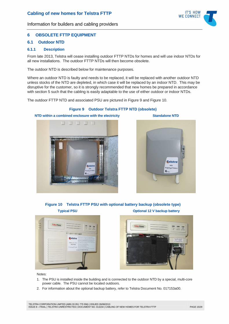
The outdoor FTTP NTD and associated PSU are pictured in Figure 9 and Figure 10.
Figure 9 Outdoor Telstra FTTP NTD (obsolete)
NTD within a combined enclosure with the electricity Standalone NTD
1. The PSU is installed inside the building and is connected to the outdoor NTD by a special, multi-core power cable. The PSU cannot be located outdoors.
2. For information about the optional backup battery, refer to Telstra Document No. 017153a00.
Cabling of new homes for Telstra FTTP
Information for builders and cabling providers
TELSTRA CORPORATION LIMITED (ABN 33 051 775 556) | ISSUED 26/08/2013 ISSUE 8 – FINAL | TELSTRA UNRESTRICTED | DOCUMENT NO. 013234 | CABLING OF NEW HOMES FOR TELSTRA FTTP
PAGE 16/29
6.1.2 Connecting customer cabling at the NTD
The outdoor NTD contains the following service ports:
4 telephone lines
1 Ethernet port for broadband data
1 coaxial port for FTA TV or FOXTEL.
Only one cable may be connected to the NTD for each of the above service categories, as follows:
a 4-pair Category 5 or Category 6 cable for the four telephone lines
a 4-pair Category 5 or Category 6 cable for the broadband data service
an RG6 coaxial cable for the FTA TV/FOXTEL connection.
Any additional cables (e.g. for additional telephone points) must be connected via an internal distribution
device or some other method.
Cabling providers may gain access to the NTD connections via the cover securing screw designated
“CUSTOMER ACCESS”, using a standard flat-blade or No.2 Phillips-head screwdriver.
Note: Despite the marking, for technical and safety reasons customers are not authorised to access the NTD.
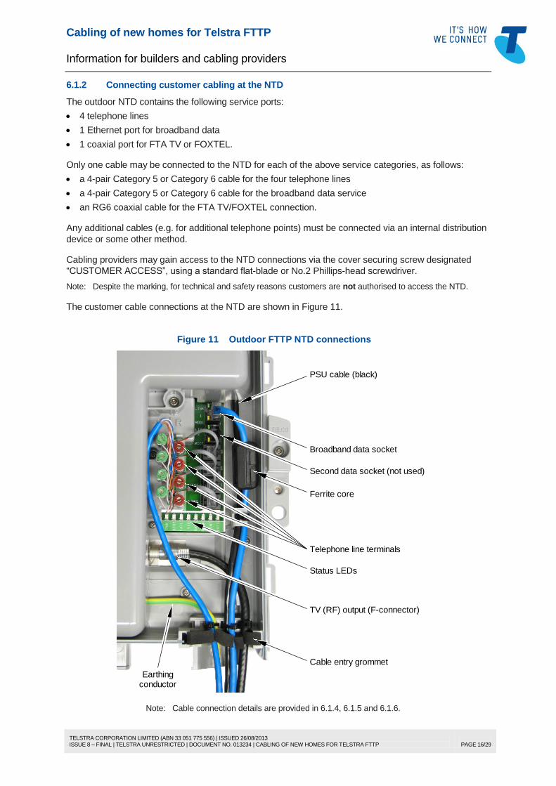
The customer cable connections at the NTD are shown in Figure 11.
Figure 11 Outdoor FTTP NTD connections
Ferrite core
Telephone line terminals
TV (RF) output (F-connector)
Status LEDs
Cable entry grommet
Earthingconductor
Broadband data socket
Second data socket (not used)
PSU cable (black)
Note: Cable connection details are provided in 6.1.4, 6.1.5 and 6.1.6.
Cabling of new homes for Telstra FTTP
Information for builders and cabling providers
TELSTRA CORPORATION LIMITED (ABN 33 051 775 556) | ISSUED 26/08/2013 ISSUE 8 – FINAL | TELSTRA UNRESTRICTED | DOCUMENT NO. 013234 | CABLING OF NEW HOMES FOR TELSTRA FTTP
PAGE 17/29
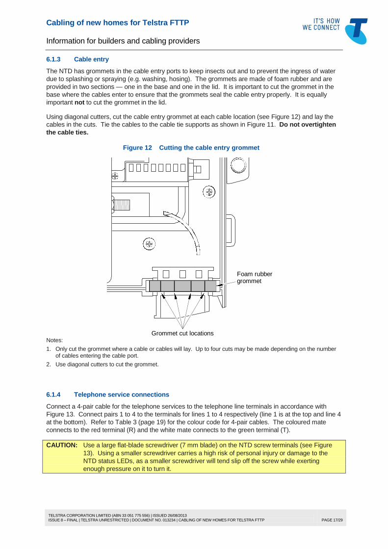
6.1.3 Cable entry
The NTD has grommets in the cable entry ports to keep insects out and to prevent the ingress of water
due to splashing or spraying (e.g. washing, hosing). The grommets are made of foam rubber and are
provided in two sections — one in the base and one in the lid. It is important to cut the grommet in the
base where the cables enter to ensure that the grommets seal the cable entry properly. It is equally
important not to cut the grommet in the lid.
Using diagonal cutters, cut the cable entry grommet at each cable location (see Figure 12) and lay the
cables in the cuts. Tie the cables to the cable tie supports as shown in Figure 11. Do not overtighten
the cable ties.
Figure 12 Cutting the cable entry grommet
Grommet cut locations
Foam rubbergrommet
Notes:
1. Only cut the grommet where a cable or cables will lay. Up to four cuts may be made depending on the number of cables entering the cable port.
2. Use diagonal cutters to cut the grommet.
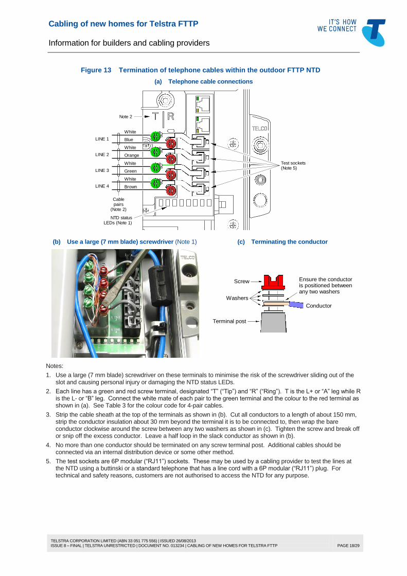
6.1.4 Telephone service connections
Connect a 4-pair cable for the telephone services to the telephone line terminals in accordance with
Figure 13. Connect pairs 1 to 4 to the terminals for lines 1 to 4 respectively (line 1 is at the top and line 4
at the bottom). Refer to Table 3 (page 19) for the colour code for 4-pair cables. The coloured mate
connects to the red terminal (R) and the white mate connects to the green terminal (T).
CAUTION: Use a large flat-blade screwdriver (7 mm blade) on the NTD screw terminals (see Figure
13). Using a smaller screwdriver carries a high risk of personal injury or damage to the
NTD status LEDs, as a smaller screwdriver will tend slip off the screw while exerting
enough pressure on it to turn it.
Cabling of new homes for Telstra FTTP
Information for builders and cabling providers
TELSTRA CORPORATION LIMITED (ABN 33 051 775 556) | ISSUED 26/08/2013 ISSUE 8 – FINAL | TELSTRA UNRESTRICTED | DOCUMENT NO. 013234 | CABLING OF NEW HOMES FOR TELSTRA FTTP
PAGE 18/29
Figure 13 Termination of telephone cables within the outdoor FTTP NTD
(a) Telephone cable connections
Note 2
White
BlueLINE 1
Cablepairs
(Note 2)
Test sockets(Note 5)
White
GreenLINE 3
White
BrownLINE 4
White
OrangeLINE 2
NTD statusLEDs (Note 1)
(b) Use a large (7 mm blade) screwdriver (Note 1) (c) Terminating the conductor
Conductor
Washers
Screw
Terminal post
Ensure the conductoris positioned betweenany two washers
Notes:
1. Use a large (7 mm blade) screwdriver on these terminals to minimise the risk of the screwdriver sliding out of the slot and causing personal injury or damaging the NTD status LEDs.
2. Each line has a green and red screw terminal, designated “T” (“Tip”) and “R” (“Ring”). T is the L+ or “A” leg while R is the L- or “B” leg. Connect the white mate of each pair to the green terminal and the colour to the red terminal as shown in (a). See Table 3 for the colour code for 4-pair cables.
3. Strip the cable sheath at the top of the terminals as shown in (b). Cut all conductors to a length of about 150 mm, strip the conductor insulation about 30 mm beyond the terminal it is to be connected to, then wrap the bare conductor clockwise around the screw between any two washers as shown in (c). Tighten the screw and break off or snip off the excess conductor. Leave a half loop in the slack conductor as shown in (b).
4. No more than one conductor should be terminated on any screw terminal post. Additional cables should be connected via an internal distribution device or some other method.
5. The test sockets are 6P modular (“RJ11”) sockets. These may be used by a cabling provider to test the lines at the NTD using a buttinski or a standard telephone that has a line cord with a 6P modular (“RJ11”) plug. For technical and safety reasons, customers are not authorised to access the NTD for any purpose.
Cabling of new homes for Telstra FTTP
Information for builders and cabling providers
TELSTRA CORPORATION LIMITED (ABN 33 051 775 556) | ISSUED 26/08/2013 ISSUE 8 – FINAL | TELSTRA UNRESTRICTED | DOCUMENT NO. 013234 | CABLING OF NEW HOMES FOR TELSTRA FTTP
PAGE 19/29
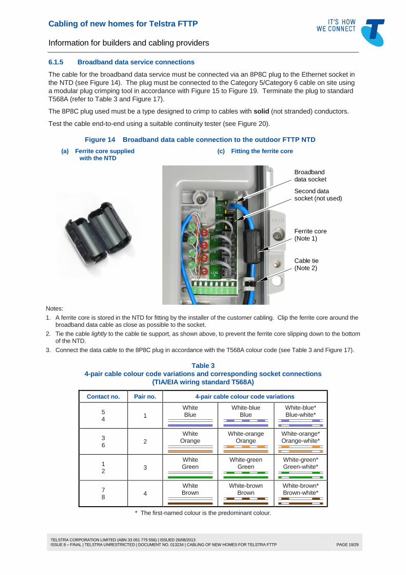
6.1.5 Broadband data service connections
The cable for the broadband data service must be connected via an 8P8C plug to the Ethernet socket in
the NTD (see Figure 14). The plug must be connected to the Category 5/Category 6 cable on site using
a modular plug crimping tool in accordance with Figure 15 to Figure 19. Terminate the plug to standard
T568A (refer to Table 3 and Figure 17).
The 8P8C plug used must be a type designed to crimp to cables with solid (not stranded) conductors.
Test the cable end-to-end using a suitable continuity tester (see Figure 20).
Figure 14 Broadband data cable connection to the outdoor FTTP NTD
(a) Ferrite core supplied with the NTD
(c) Fitting the ferrite core
Ferrite core
Second data
Broadband
Cable tie
data socket
socket (not used)
(Note 1)
(Note 2)
Notes:
1. A ferrite core is stored in the NTD for fitting by the installer of the customer cabling. Clip the ferrite core around the broadband data cable as close as possible to the socket.
2. Tie the cable lightly to the cable tie support, as shown above, to prevent the ferrite core slipping down to the bottom of the NTD.
3. Connect the data cable to the 8P8C plug in accordance with the T568A colour code (see Table 3 and Figure 17).
Table 3
4-pair cable colour code variations and corresponding socket connections
* The first-named colour is the predominant colour.
Cabling of new homes for Telstra FTTP
Information for builders and cabling providers
TELSTRA CORPORATION LIMITED (ABN 33 051 775 556) | ISSUED 26/08/2013 ISSUE 8 – FINAL | TELSTRA UNRESTRICTED | DOCUMENT NO. 013234 | CABLING OF NEW HOMES FOR TELSTRA FTTP
PAGE 20/29
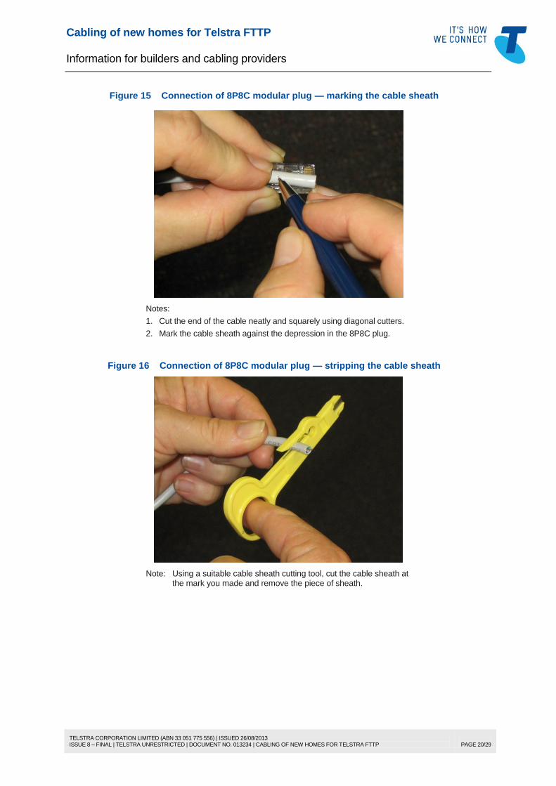
Figure 15 Connection of 8P8C modular plug — marking the cable sheath
Notes:
1. Cut the end of the cable neatly and squarely using diagonal cutters.
2. Mark the cable sheath against the depression in the 8P8C plug.
Figure 16 Connection of 8P8C modular plug — stripping the cable sheath
Note: Using a suitable cable sheath cutting tool, cut the cable sheath at the mark you made and remove the piece of sheath.
Cabling of new homes for Telstra FTTP
Information for builders and cabling providers
TELSTRA CORPORATION LIMITED (ABN 33 051 775 556) | ISSUED 26/08/2013 ISSUE 8 – FINAL | TELSTRA UNRESTRICTED | DOCUMENT NO. 013234 | CABLING OF NEW HOMES FOR TELSTRA FTTP
PAGE 21/29
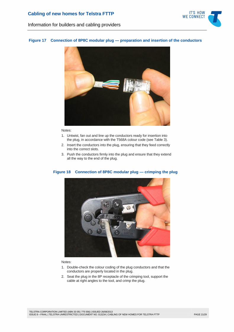
Figure 17 Connection of 8P8C modular plug — preparation and insertion of the conductors
Notes:
1. Untwist, fan out and line up the conductors ready for insertion into the plug, in accordance with the T568A colour code (see Table 3).
2. Insert the conductors into the plug, ensuring that they feed correctly into the correct slots.
3. Push the conductors firmly into the plug and ensure that they extend all the way to the end of the plug.
Figure 18 Connection of 8P8C modular plug — crimping the plug
Notes:
1. Double-check the colour coding of the plug conductors and that the conductors are properly located in the plug.
2. Seat the plug in the 8P receptacle of the crimping tool, support the cable at right angles to the tool, and crimp the plug.
Cabling of new homes for Telstra FTTP
Information for builders and cabling providers
TELSTRA CORPORATION LIMITED (ABN 33 051 775 556) | ISSUED 26/08/2013 ISSUE 8 – FINAL | TELSTRA UNRESTRICTED | DOCUMENT NO. 013234 | CABLING OF NEW HOMES FOR TELSTRA FTTP
PAGE 22/29
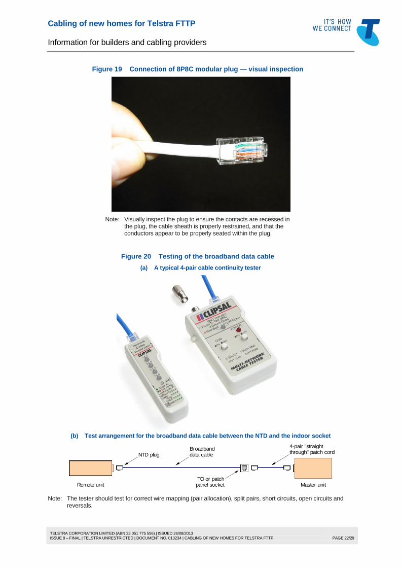
Figure 19 Connection of 8P8C modular plug — visual inspection
Note: Visually inspect the plug to ensure the contacts are recessed in the plug, the cable sheath is properly restrained, and that the conductors appear to be properly seated within the plug.
Figure 20 Testing of the broadband data cable
(a) A typical 4-pair cable continuity tester
(b) Test arrangement for the broadband data cable between the NTD and the indoor socket
NTD plug data cablethrough" patch cord
Broadband4-pair "straight
Remote unitTO or patch
Master unitpanel socket
Note: The tester should test for correct wire mapping (pair allocation), split pairs, short circuits, open circuits and reversals.
Cabling of new homes for Telstra FTTP
Information for builders and cabling providers
TELSTRA CORPORATION LIMITED (ABN 33 051 775 556) | ISSUED 26/08/2013 ISSUE 8 – FINAL | TELSTRA UNRESTRICTED | DOCUMENT NO. 013234 | CABLING OF NEW HOMES FOR TELSTRA FTTP
PAGE 23/29
6.1.6 Coaxial cable connection for FTA TV/FOXTEL
Connect the coaxial cable to the TV port (female F-connector) on the NTD using an external-rated male
F-connector, as shown in Figure 21. For guidance on fitting F-connectors to coaxial cable, refer to
Telstra Document No. 017153a00.
It is not possible to leave any slack coaxial cable in the NTD. However, leave sufficient free play in the
cable to allow the F-connector to be connected and disconnected without exerting strain on the cable.
CAUTION: Once TV appliances are connected to the coaxial cabling, an electrical hazard may be
present on the coaxial cable due to leakage currents or a faulty appliance. Follow proper
electrical safety precautions when connecting the F-connector to the RF port of the NTD.
Figure 21 Coaxial cable connection in the outdoor FTTP NTD
flangeguide
Coaxialcable
Cable
F-connectorrated
External
Notes:
1. Run the cable to the right of the cable guide flange to ensure that the required minimum cable bend radius is maintained and that there is sufficient free play in the cable to disconnect and reconnect the F-connector.
2. Use an external-rated female F-connector. Tighten the F-connector on the threaded TV output port using a torque wrench set to 20-30 inch lbs.
3. The barrel of the F-connector of the NTD is earthed via the earthing conductor described in 6.1.7.
Coaxial cabling guidelines are provided in Telstra Document No. 017153a00 and may be applied to
coaxial cabling connected to a Telstra FTTP NTD. For calculation of losses for the purpose of designing
the coaxial cabling system as described in Document No. 017153a00, the expected RF signal levels at
the F-connector of the outdoor FTTP NTD are provided in Table 4.
Table 4 Expected RF power levels at the F-connector of the outdoor NTD
Operating bandwidth Signal level BER MER
85 MHz to 750 MHz 63 dBµV (minimum)
80 dBµV (maximum) > 1x10
-8 ≥ 32 dB
Note: All RF signal levels are digital channel power levels measured in an 8 MHz bandwidth.
Assuming the minimum signal level of 63 dBµV and without using an RF amplifier, 3 coaxial sockets may
be cabled up to 25 m from the NTD (via a 3-way splitter) or 2 coaxial sockets may be cabled up to 40 m
from the NTD (via a 2-way splitter). Longer cabling distances or more sockets may be possible if the
signal level from the NTD is higher (the RF signal level depends on the optical power level at the NTD).
6.1.7 PSU cable and earthing conductor
The PSU cable enters the right-hand cable entry port and passes under the broadband internet cable on
the right side of the NTD into the top of the Telstra (“Telco”) compartment. This is a black cable and can
be seen in Figure 11.
The earthing conductor can enter either the right-hand or left-hand cable port, whichever is more
convenient. This cable is connected at the bottom of the Telstra (“Telco”) compartment.
The PSU cable and the earthing conductor are connected by Telstra.
Cabling of new homes for Telstra FTTP
Information for builders and cabling providers
TELSTRA CORPORATION LIMITED (ABN 33 051 775 556) | ISSUED 26/08/2013 ISSUE 8 – FINAL | TELSTRA UNRESTRICTED | DOCUMENT NO. 013234 | CABLING OF NEW HOMES FOR TELSTRA FTTP
PAGE 24/29
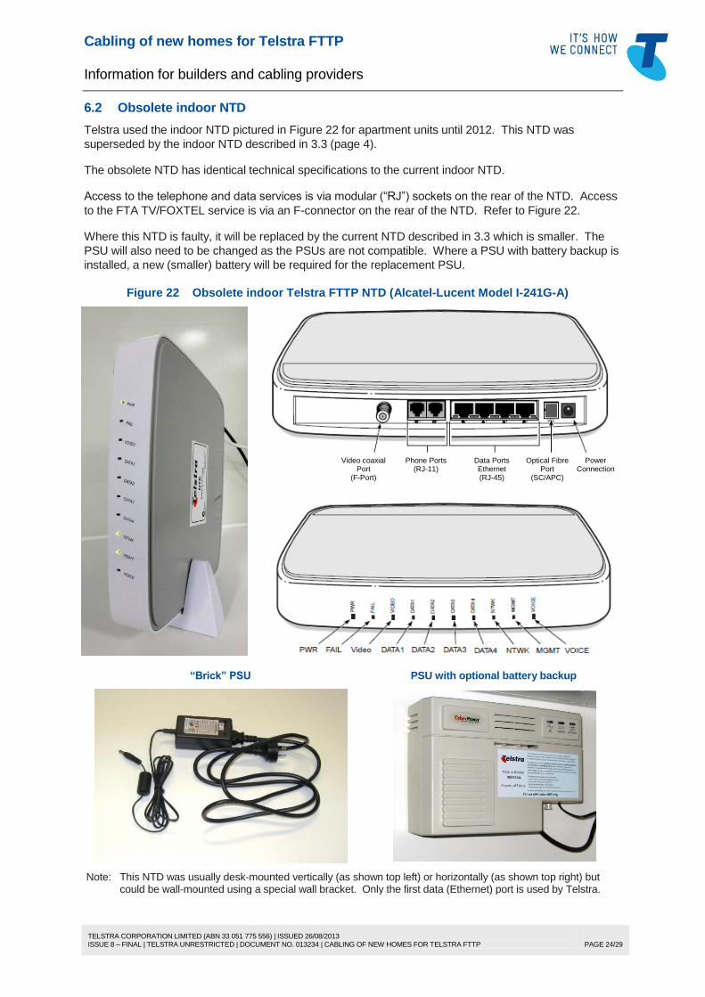
6.2 Obsolete indoor NTD
Telstra used the indoor NTD pictured in Figure 22 for apartment units until 2012. This NTD was
superseded by the indoor NTD described in 3.3 (page 4).
The obsolete NTD has identical technical specifications to the current indoor NTD.
Access to the telephone and data services is via modular (“RJ”) sockets on the rear of the NTD. Access
to the FTA TV/FOXTEL service is via an F-connector on the rear of the NTD. Refer to Figure 22.
Where this NTD is faulty, it will be replaced by the current NTD described in 3.3 which is smaller. The
PSU will also need to be changed as the PSUs are not compatible. Where a PSU with battery backup is
installed, a new (smaller) battery will be required for the replacement PSU.
Figure 22 Obsolete indoor Telstra FTTP NTD (Alcatel-Lucent Model I-241G-A)
Video coaxial Port
(F-Port)
Phone Ports (RJ-11)
Data Ports Ethernet (RJ-45)
Optical Fibre Port
(SC/APC)
Power Connection
“Brick” PSU PSU with optional battery backup
Note: This NTD was usually desk-mounted vertically (as shown top left) or horizontally (as shown top right) but could be wall-mounted using a special wall bracket. Only the first data (Ethernet) port is used by Telstra.
Cabling of new homes for Telstra FTTP
Information for builders and cabling providers
TELSTRA CORPORATION LIMITED (ABN 33 051 775 556) | ISSUED 26/08/2013 ISSUE 8 – FINAL | TELSTRA UNRESTRICTED | DOCUMENT NO. 013234 | CABLING OF NEW HOMES FOR TELSTRA FTTP
PAGE 25/29
7 DEFINITIONS
Term Definition
AWG American Wire Gauge
builder A person charged with the construction or renovation of any building
building A substantial construction intended to protect persons, animals, vehicles,
machinery, tools or equipment from the weather
building entry point The point on a building where telecommunications cabling enters the
building
cabling Cable or cables and any associated works or parts such as pits, poles,
conduits, trays, connecting devices, jumpers, etc.
cabling provider A person registered as a cabling provider under the Cabling Provider
Rules (also referred to as a “cabler”)
Cabling Provider Rules The Telecommunications Cabling Provider Rules 2000
CCP Central Connection Point — a device provided as a central cable
connection point for the home cabling, which may be a single, multi-socket
wall plate or a patch panel
conduit A tube or pipe that physically accommodates cables
customer A person who subscribes to (pays for) the supply of a telecommunications
network service or an end-user of that service
customer cabling Any cabling connected on the customer’s side of the NTD
customer equipment Any equipment connected on the customer’s side of the NTD
data A general term used to describe digital information or any cable, device or
port designed to carry digital signals
distributor A collection of components used to terminate cables and which provides
facilities for cross-connection by means of jumpers or patch cords
earth An electrical connection to the mass of earth. This can be made by driving
or burying a metal electrode in the ground but, within customer premises,
is usually – and should be – made via a connection to the earthing bar or
terminal of the electrical switchboard or to the earth electrode of the
electrical earthing system. Earth may also be described as “ground”.
earthing The act of connecting equipment or cabling to an earth reference such as
to the electrical earthing system of the electrical installation or an earth
electrode. Earthing may also be described as “grounding”.
Ethernet A standard for interconnecting computers via a local area network (LAN)
Cabling of new homes for Telstra FTTP
Information for builders and cabling providers
TELSTRA CORPORATION LIMITED (ABN 33 051 775 556) | ISSUED 26/08/2013 ISSUE 8 – FINAL | TELSTRA UNRESTRICTED | DOCUMENT NO. 013234 | CABLING OF NEW HOMES FOR TELSTRA FTTP
PAGE 26/29
Term Definition
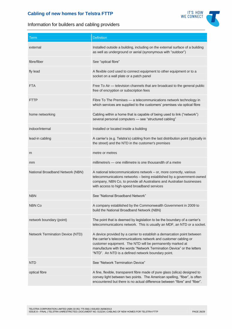
external Installed outside a building, including on the external surface of a building
as well as underground or aerial (synonymous with “outdoor”)
fibre/fiber See “optical fibre”
fly lead A flexible cord used to connect equipment to other equipment or to a
socket on a wall plate or a patch panel
FTA Free To Air — television channels that are broadcast to the general public
free of encryption or subscription fees
FTTP Fibre To The Premises — a telecommunications network technology in
which services are supplied to the customers’ premises via optical fibre
home networking Cabling within a home that is capable of being used to link (“network”)
several personal computers — see “structured cabling”
indoor/internal Installed or located inside a building
lead-in cabling A carrier’s (e.g. Telstra’s) cabling from the last distribution point (typically in
the street) and the NTD in the customer's premises
m metre or metres
mm millimetre/s — one millimetre is one thousandth of a metre
National Broadband Network (NBN) A national telecommunications network – or, more correctly, various
telecommunications networks – being established by a government-owned
company, NBN Co, to provide all Australians and Australian businesses
with access to high-speed broadband services
NBN See “National Broadband Network”
NBN Co A company established by the Commonwealth Government in 2009 to
build the National Broadband Network (NBN)
network boundary (point) The point that is deemed by legislation to be the boundary of a carrier’s
telecommunications network. This is usually an MDF, an NTD or a socket.
Network Termination Device (NTD) A device provided by a carrier to establish a demarcation point between
the carrier’s telecommunications network and customer cabling or
customer equipment. The NTD will be permanently marked at
manufacture with the words “Network Termination Device” or the letters
“NTD”. An NTD is a defined network boundary point.
NTD See “Network Termination Device”
optical fibre A fine, flexible, transparent fibre made of pure glass (silica) designed to
convey light between two points. The American spelling, “fiber”, is often
encountered but there is no actual difference between “fibre” and “fiber”.
Cabling of new homes for Telstra FTTP
Information for builders and cabling providers
TELSTRA CORPORATION LIMITED (ABN 33 051 775 556) | ISSUED 26/08/2013 ISSUE 8 – FINAL | TELSTRA UNRESTRICTED | DOCUMENT NO. 013234 | CABLING OF NEW HOMES FOR TELSTRA FTTP
PAGE 27/29
Term Definition
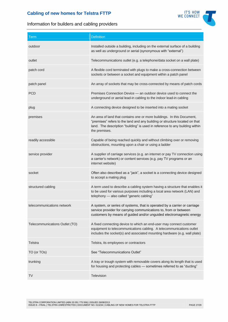
outdoor Installed outside a building, including on the external surface of a building
as well as underground or aerial (synonymous with “external”)
outlet Telecommunications outlet (e.g. a telephone/data socket on a wall plate)
patch cord A flexible cord terminated with plugs to make a cross-connection between
sockets or between a socket and equipment within a patch panel
patch panel An array of sockets that may be cross-connected by means of patch cords
PCD Premises Connection Device — an outdoor device used to connect the
underground or aerial lead-in cabling to the indoor lead-in cabling
plug A connecting device designed to be inserted into a mating socket
premises An area of land that contains one or more buildings. In this Document,
“premises” refers to the land and any building or structure located on that
land. The description “building” is used in reference to any building within
the premises.
readily accessible Capable of being reached quickly and without climbing over or removing
obstructions, mounting upon a chair or using a ladder
service provider A supplier of carriage services (e.g. an internet or pay TV connection using
a carrier’s network) or content services (e.g. pay TV programs or an
internet website)
socket Often also described as a “jack”, a socket is a connecting device designed
to accept a mating plug
structured cabling A term used to describe a cabling system having a structure that enables it
to be used for various purposes including a local area network (LAN) and
telephony — also called “generic cabling”
telecommunications network A system, or series of systems, that is operated by a carrier or carriage
service provider for carrying communications to, from or between
customers by means of guided and/or unguided electromagnetic energy
Telecommunications Outlet (TO) A fixed connecting device to which an end-user may connect customer
equipment to telecommunications cabling. A telecommunications outlet
includes the socket(s) and associated mounting hardware (e.g. wall plate)
Telstra Telstra, its employees or contractors
TO (or TOs) See “Telecommunications Outlet”
trunking A tray or trough system with removable covers along its length that is used
for housing and protecting cables — sometimes referred to as “ducting”
TV Television
Cabling of new homes for Telstra FTTP
Information for builders and cabling providers
TELSTRA CORPORATION LIMITED (ABN 33 051 775 556) | ISSUED 26/08/2013 ISSUE 8 – FINAL | TELSTRA UNRESTRICTED | DOCUMENT NO. 013234 | CABLING OF NEW HOMES FOR TELSTRA FTTP
PAGE 28/29
8 REFERENCES
Document number Title
017153a00 Cabling of premises for telecommunications — A complete guide to home
cabling
017153a01 Cabling of premises for telecommunications — Essential information for
home cabling
017153a02 Cabling of premises for telecommunications — Lead-in cabling and
building entry facilities for homes
Cabling of new homes for Telstra FTTP
Information for builders and cabling providers
TELSTRA CORPORATION LIMITED (ABN 33 051 775 556) | ISSUED 26/08/2013 ISSUE 8 – FINAL | TELSTRA UNRESTRICTED | DOCUMENT NO. 013234 | CABLING OF NEW HOMES FOR TELSTRA FTTP
PAGE 29/29
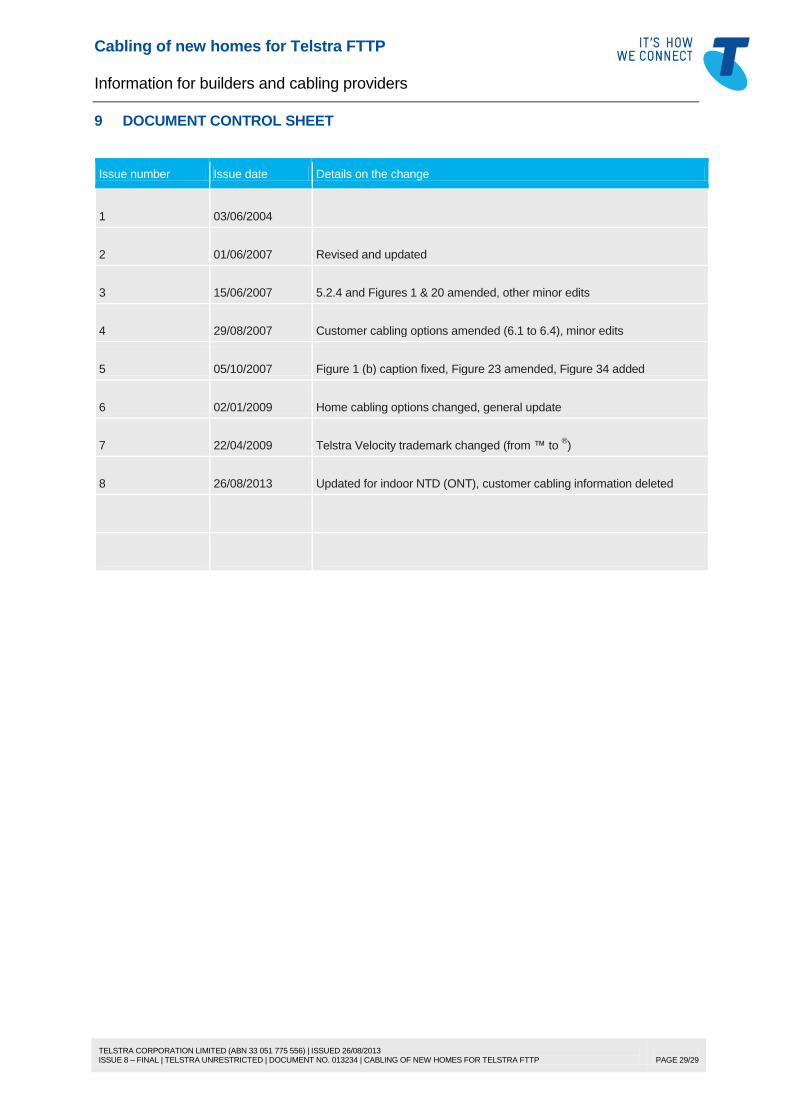
9 DOCUMENT CONTROL SHEET
Issue number Issue date Details on the change
1 03/06/2004
2 01/06/2007 Revised and updated
3 15/06/2007 5.2.4 and Figures 1 & 20 amended, other minor edits
4 29/08/2007 Customer cabling options amended (6.1 to 6.4), minor edits