148
Pro/ENGINEER ® Wildfire ™ 3.0 Cabling Help Topic Collection Parametric Technology Corporation
| Date post: | 08-Nov-2014 |
| Category: |
Documents |
| Upload: | little-aya |
| View: | 61 times |
| Download: | 2 times |

Pro/ENGINEER®
Wildfire™ 3.0
Cabling Help Topic Collection
Parametric Technology Corporation

Copyright © 2006 Parametric Technology Corporation. All Rights Reserved.
User and training documentation from Parametric Technology Corporation and its subsidiary companies (PTC) is subject to the
copyright laws of the United States and other countries and is provided under a license agreement that restricts copying, disclosure,
and use of such documentation. PTC hereby grants to the licensed user the right to make copies in printed form of this documentation
if provided on software media, but only for internal/personal use and in accordance with the license agreement under which the
applicable software is licensed. Any copy made shall include the PTC copyright notice and any other proprietary notice provided by
PTC. This documentation may not be disclosed, transferred, modified, or reduced to any form, including electronic media, or
transmitted or made publicly available by any means without the prior written consent of PTC and no authorization is granted to make
copies for such purposes.
Information described herein is furnished for general information only, is subject to change without notice, and should not be
construed as a warranty or commitment by PTC. PTC assumes no responsibility or liability for any errors or inaccuracies that may
appear in this document.
The software described in this document is provided under written license agreement, contains valuable trade secrets and proprietary
information, and is protected by the copyright laws of the United States and other countries. It may not be copied or distributed in any
form or medium, disclosed to third parties, or used in any manner not provided for in the software licenses agreement except with
written prior approval from PTC. UNAUTHORIZED USE OF SOFTWARE OR ITS DOCUMENTATION CAN RESULT IN CIVIL
DAMAGES AND CRIMINAL PROSECUTION.
Registered Trademarks of Parametric Technology Corporation or a Subsidiary
Advanced Surface Design, Arbortext, Behavioral Modeling, CADDS, Computervision, CounterPart, Create � Collaborate � Control,
EPD, EPD.Connect, Expert Machinist, Flexible Engineering, GRANITE, HARNESSDESIGN, Info*Engine, InPart, MECHANICA,
Optegra, Parametric Technology, Parametric Technology Corporation, PartSpeak, PHOTORENDER, Pro/DESKTOP, Pro/E,
Pro/ENGINEER, Pro/HELP, Pro/INTRALINK, Pro/MECHANICA, Pro/TOOLKIT, Product First,
Product Development Means Business, Product Makes the Company, PTC, the PTC logo, PT/Products, Shaping Innovation,
Simple � Powerful � Connected, The Way to Product First, and Windchill.
Trademarks of Parametric Technology Corporation or a Subsidiary
3DPAINT, Arbortext Editor, Arbortext Contributor, Arbortext Companion for MS Word®, Arbortext Advanced Print Publisher –
Desktop, Arbortext Advanced Print Publisher – Enterprise, Arbortext Publishing Engine, Arbortext Dynamic Link Manager,
Arbortext Styler, Arbortext Architect, Arbortext Digital Media Publisher, Arbortext Adapter to Documentum®,
Arbortext Adapter to Oracle®, Associative Topology Bus, AutobuildZ, CDRS, CV, CVact, CVaec, CVdesign, CV-DORS, CVMAC,
CVNC, CVToolmaker, Create � Collaborate � Control � Communicate, EDAcompare, EDAconduit, DataDoctor, DesignSuite,
DIMENSION III, Distributed Services Manager, DIVISION, e/ENGINEER, eNC Explorer, Expert Framework, Expert MoldBase,
Expert Toolmaker, FlexPDM, FlexPLM, Harmony, InterComm, InterComm Expert, InterComm EDAcompare,
InterComm EDAconduit, ISSM, KDiP, Knowledge Discipline in Practice, Knowledge System Driver, ModelCHECK, MoldShop,
NC Builder, POLYCAPP, Pro/ANIMATE, Pro/ASSEMBLY, Pro/CABLING, Pro/CASTING, Pro/CDT, Pro/CMM,
Pro/COLLABORATE, Pro/COMPOSITE, Pro/CONCEPT, Pro/CONVERT, Pro/DATA for PDGS, Pro/DESIGNER, Pro/DETAIL,
Pro/DIAGRAM, Pro/DIEFACE, Pro/DRAW, Pro/ECAD, Pro/ENGINE, Pro/FEATURE, Pro/FEM-POST, Pro/FICIENCY,
Pro/FLY-THROUGH, Pro/HARNESS, Pro/INTERFACE, Pro/LANGUAGE, Pro/LEGACY, Pro/LIBRARYACCESS, Pro/MESH,
Pro/Model.View, Pro/MOLDESIGN, Pro/NC-ADVANCED, Pro/NC-CHECK, Pro/NC-MILL, Pro/NC-POST,
Pro/NC-SHEETMETAL, Pro/NC-TURN, Pro/NC-WEDM, Pro/NC-Wire EDM, Pro/NETWORK ANIMATOR, Pro/NOTEBOOK,
Pro/PDM, Pro/PHOTORENDER, Pro/PIPING, Pro/PLASTIC ADVISOR, Pro/PLOT, Pro/POWER DESIGN, Pro/PROCESS,
Pro/REPORT, Pro/REVIEW, Pro/SCAN-TOOLS, Pro/SHEETMETAL, Pro/SURFACE, Pro/VERIFY, Pro/Web.Link,
Pro/Web.Publish, Pro/WELDING, ProductView, PTC Precision, Routed Systems Designer, Shrinkwrap,
The Product Development Company, Validation Manager, Warp, Wildfire, Windchill DynamicDesignLink, Windchill PartsLink,
Windchill PDMLink, Windchill ProjectLink, and Windchill SupplyLink.
Patents of Parametric Technology Corporation or a Subsidiary
Registration numbers and issue dates follow. Additionally, equivalent patents may be issued or pending outside of the United States.
Contact PTC for further information. GB2366639B 13-October-2004. GB2363208 25-August-2004. (EP/DE/GB)0812447 26-
May-2004. GB2365567 10-March-2004. (GB)2388003B 21-January-2004. 6,665,569 B1 16-December-2003. GB2353115 10-
December-2003. 6,625,607 B1 23-September-2003. 6,580,428 B1 17-June-2003. GB2354684B 02-July-2003. GB2384125 15-
October-2003. GB2354096 12-November-2003. GB2354924 24-September-2003. 6,608,623 B1 19-August-2003. GB2353376
05-November-2003. GB2354686 15-October-2003. 6,545,671 B1 08-April-2003. GB2354685B 18-June-2003. GB2354683B 04-
June-2003. 6,608,623 B1 19-August-2003. 6,473,673 B1 29-October-2002. GB2354683B 04-June-2003. 6,447,223 B1 10-Sept-
2002. 6,308,144 23-October-2001. 5,680,523 21-October-1997. 5,838,331 17-November-1998. 4,956,771 11-
September-1990. 5,058,000 15-October-1991. 5,140,321 18-August-1992. 5,423,023 05-June-1990. 4,310,615 21-December-
1998. 4,310,614 30-April-1996. 4,310,614 22-April-1999. 5,297,053 22-March-1994. 5,513,316 30-April-1996. 5,689,711 18-
November-1997. 5,506,950 09-April-1996. 5,428,772 27-June-1995. 5,850,535 15-December-1998. 5,557,176
09-November-1996. 5,561,747 01-October-1996. (EP)0240557 02-October-1986.
Third-Party Trademarks
Adobe, Acrobat, Distiller, and the Acrobat logo are trademarks of Adobe Systems Incorporated. IBM, AIX, and Websphere are
registered trademarks of IBM Corporation. Allegro, Cadence, and Concept are registered trademarks of Cadence Design Systems, Inc.
Apple, Mac, Mac OS, Panther and Tiger are trademarks or registered trademarks of Apple Computer, Inc. AutoCAD and
Autodesk Inventor are registered trademarks of Autodesk, Inc. Baan is a registered trademark of Baan Company. CADAM and

CATIA are registered trademarks of Dassault Systemes. DataDirect Connect is a registered trademark of DataDirect Technologies.
CYA, iArchive, HOTbackup, and Virtual StandBy are trademarks or registered trademarks of CYA Technologies, Inc. DOORS is a
registered trademark of Telelogic AB. FLEXnet, InstallShield, and InstallAnywhere are trademarks or registered trademarks of
Macrovision Corporation. Geomagic is a registered trademark of Raindrop Geomagic, Inc. EVERSYNC, GROOVE, GROOVEFEST,
GROOVE.NET, GROOVE NETWORKS, iGROOVE, PEERWARE, and the interlocking circles logo are trademarks of Groove
Networks, Inc. Helix is a trademark of Microcadam, Inc. HOOPS is a trademark of Tech Soft America, Inc. HP, Hewlett-Packard, and
HP-UX are registered trademarks of Hewlett-Packard Company. Advanced ClusterProven, ClusterProven, the ClusterProven design,
Rational Rose, and Rational ClearCase are trademarks or registered trademarks of International Business Machines in the United
States and other countries and are used under license. IBM Corporation does not warrant and is not responsible for the operation of
this software product. I-DEAS, Metaphase, Parasolid, SHERPA, Solid Edge, TeamCenter, UG-NX, and Unigraphics are trademarks
or registered trademarks of UGS Corp. Intel is a registered trademark of Intel Corporation. IRIX is a registered trademark of Silicon
Graphics, Inc. I-Run and ISOGEN are registered trademarks of Alias Ltd. LINUX is a registered trademark of Linus Torvalds.
MainWin and Mainsoft are trademarks of Mainsoft Corporation. MatrixOne is a trademark of MatrixOne, Inc. Mentor Graphics and
Board Station are registered trademarks and 3D Design, AMPLE, and Design Manager are trademarks of Mentor Graphics
Corporation. MEDUSA and STHENO are trademarks of CAD Schroer GmbH. Microsoft, ActiveX, JScript, Windows, Windows NT,
Windows 2000, Windows 2000 Server, Windows XP, Windows Server 2003, the Windows logo, Visual Basic, the Visual Basic logo,
and Active Accessibility are trademarks or registered trademarks of Microsoft Corporation in the United States and/or other countries.
Moldflow is a registered trademark of Moldflow Corporation. Netscape and the Netscape N and Ship's Wheel logos are registered
trademarks of Netscape Communications Corporation in the U.S. and other countries. Oracle and interMedia are registered trademarks
of Oracle Corporation. OrbixWeb is a registered trademark of IONA Technologies PLC. PDGS is a registered trademark of Ford
Motor Company. RAND is a trademark of RAND Worldwide. RetrievalWare is a registered trademark of Convera Corporation.
RosettaNet is a trademark and Partner Interface Process and PIP are registered trademarks of RosettaNet, a nonprofit organization.
SAP and R/3 are registered trademarks of SAP AG Germany. SolidWorks is a registered trademark of SolidWorks Corporation. All
SPARC trademarks are used under license and are trademarks or registered trademarks of SPARC International, Inc. in the United
States and in other countries. Products bearing SPARC trademarks are based upon an architecture developed by Sun Microsystems,
Inc. Sun, Sun Microsystems, the Sun logo, Solaris, UltraSPARC, Java and all Java based marks, and “The Network is the Computer”
are trademarks or registered trademarks of Sun Microsystems, Inc. in the United States and in other countries. 3Dconnexion is a
registered trademark of Logitech International S.A. TIBCO is a registered trademark and TIBCO ActiveEnterprise, TIBCO Designer,
TIBCO Enterprise Message Service, TIBCO Rendezvous, TIBCO TurboXML, and TIBCO BusinessWorks are trademarks or
registered trademarks of TIBCO Software Inc. in the United States and other countries. WebEx is a trademark of WebEx
Communications, Inc. API Tookit is a trademark of InterCAP Graphics Systems, Inc. BEA and WebLogic are registered trademarks
of BEA Systems, Inc. BEA WebLogic Server and BEA WebLogic Platform are trademarks of BEA Systems, Inc. Compaq is a
registered trademark of Compaq Computer Corporation. DEC is a registered trademark of Digital Equipment Corporation.
Documentum and Documentum Administrator are trademarks of Documentum, Inc. Elan License Manager and Softlock are
trademarks of Rainbow Technologies, Inc. JAWS is a registered trademark of Freedom Scientific BLV Group, LLC in the United
States and other countries. FileNET is a registered trademark of FileNET Corporation. Panagon is a trademark of FileNET
Corporation. Galaxy Application Environment is a licensed trademark of Visix Software, Inc. Interleaf is a trademark of Interleaf, Inc.
IslandDraw and IslandPaint are trademarks of Island Graphics Corporation. Netscape, Netscape Navigator, and
Netscape Communicator are registered trademarks and service marks of Netscape Communications Corporation. OSF/Motif and
Motif are trademarks of the Open Software Foundation, Inc. Palm Computing, Palm OS, Graffiti, HotSync, and Palm Modem are
registered trademarks, and Palm III, Palm IIIe, Palm IIIx, Palm V, Palm Vx, Palm VII, Palm, More connected, Simply Palm, the Palm
Computing platform logo, all Palm logos, and HotSync logo are trademarks of Palm, Inc. or its subsidiaries. Proximity and Linguibase
are registered trademarks of Proximity Technology, Inc. SPARC is a registered trademark and SPARCStation is a trademark of
SPARC International, Inc. (products bearing the SPARC trademarks are based on an architecture developed by Sun
Microsystems, Inc.). TeX is a trademark of the American Mathematical Society. UNIX is a registered trademark of The Open Group.
X Window System is a trademark of X Consortium, Inc.
Third-Party Technology Information
Certain PTC software products contain licensed third-party technology:
Rational Rose and Rational ClearCase are copyrighted software of IBM Corp.
RetrievalWare is copyrighted software of Convera Corporation.
VisTools library is copyrighted software of Visual Kinematics, Inc. (VKI) containing confidential trade secret information belonging
to VKI.
HOOPS graphics system is a proprietary software product of, and is copyrighted by, Tech Soft America, Inc.
I-Run and ISOGEN are copyrighted software of Alias Ltd.
Xdriver is copyrighted software of 3Dconnexion, Inc, a Logitech International S.A. company.
G-POST is copyrighted software and a registered trademark of Intercim.
VERICUT is copyrighted software and a registered trademark of CGTech.
FLEXnet Publisher is copyrighted software of Macrovision Corporation.
Pro/PLASTIC ADVISOR is powered by Moldflow technology.
Fatigue Advisor nCode libraries from nCode International.

TetMesh-GHS3D provided by Simulog Technologies, a business unit of Simulog S.A.
MainWin Dedicated Libraries are copyrighted software of Mainsoft Corporation.
DFORMD.DLL is copyrighted software from Compaq Computer Corporation and may not be distributed.
LightWork Libraries are copyrighted by LightWork Design 1990–2001.
Visual Basic for Applications and Internet Explorer is copyrighted software of Microsoft Corporation.
Parasolid is © UGS Corp.
TECHNOMATIX is copyrighted software and contains proprietary information of Technomatix Technologies Ltd.
TIBCO ActiveEnterprise, TIBCO Designer, TIBCO Enterprise Message Service, TIBCO Rendezvous, TIBCO TurboXML, and
TIBCO BusinessWorks are provided by TIBCO Software Inc.
DataDirect Connect is copyrighted software of DataDirect Technologies.
Technology "Powered by Groove" is provided by Groove Networks, Inc.
Technology "Powered by WebEx" is provided by WebEx Communications, Inc.
Oracle 8i run-time, Oracle 9i run-time, and Oracle 10g run-time are Copyright 2002–2004 Oracle Corporation. Oracle programs
provided herein are subject to a restricted use license and can only be used in conjunction with the PTC software they are provided
with.
Adobe Acrobat Reader and Adobe Distiller are copyrighted software of Adobe Systems Inc. and are subject to the Adobe End-User
License Agreement as provided by Adobe with those products.
Certain license management is based on Elan License Manager © 1989-1999 Rainbow Technologies, Inc. All rights reserved.
Portions compiled from Microsoft Developer Network Redistributable Sample Code, Copyright © 1998 by Microsoft Corporation.
The CD-ROM Composer and CD-ROM Consumer are based on Vivace CD-Web Composer Integrator © 1996-1997 KnowledgeSet
Corporation. All rights reserved.
Larson CGM Engine 8.0, Copyright © 1992-2002 Larson Software Technology, Inc. All rights reserved.
Certain graphics-handling portions are based on the following technologies:
GIF: Copyright 1989, 1990 Kirk L. Johnson. The author disclaims all warranties with regard to this software, including all implied
warranties of merchantability and fitness. In no event shall the author be liable for any special, indirect, or consequential damages
or any damages whatsoever resulting from loss of use, data or profits, whether in an action of contract, negligence, or other
tortious action, arising out of or in connection with the use or performance of this software.
JPEG: This software is based in part on the work of the Independent JPEG Group.
PNG: Copyright 2000, 2001 Glenn Randers-Pehrson.
TIFF: Copyright 1988-1997 Sam Leffler, Copyright © 1991-1997 Silicon Graphics, Inc. The software is provided AS IS and
without warranty of any kind, express, implied, or otherwise, including without limitation, any warranty of merchantability or
fitness for a particular purpose. In no event shall Sam Leffler or Silicon Graphics be liable for any special, incidental, indirect, or
consequential damages of any kind, or any damages whatsoever resulting from loss of use, data or profits, whether or not advised
of the possibility of damage, or on any theory of liability, arising out of or in connection with the use or performance of this
software.
XBM, Sun Raster, and Sun Icon: Copyright,1987, Massachusetts Institute of Technology.
ZLIB: Copyright 1995-1998 Jean-loup Gailly and Mark Adler.
PDFlib software is copyright © 1997-2003 PDFlib GmbH. All rights reserved.
PStill software is copyright © Dipl.- Ing. Frank Siegert, 1996-2004
Proximity Linguistic Technology provides spelling portions of certain software products: The Proximity/Bertelsmann Lexikon Verlag
Database. Copyright © 1997 Bertelsmann Lexikon Verlag. Copyright © 1997, All Rights Reserved, Proximity Technology, Inc.; The
Proximity/C.A. Strombertg AB Database. Copyright © 1989 C.A. Strombertg AB. Copyright © 1989, All Rights Reserved, Proximity
Technology, Inc.; The Proximity/Editions Fernand Nathan Database. Copyright © 1984 Editions Fernand Nathan. Copyright © 1989,
All Rights Reserved, Proximity Technology, Inc.; The Proximity/Espasa-Calpe Database. Copyright © 1990 Espasa-Calpe. Copyright
© 1990, All Rights Reserved, Proximity Technology, Inc.; The Proximity/Dr. Lluis de Yzaguirre i Maura Database. Copyright © 1991
Dr. Lluis de Yzaguirre i Maura Copyright © 1991, All Rights Reserved, Proximity Technology, Inc.; The Proximity/Franklin
Electronic Publishers, Inc. Database. Copyright © 1994 Franklin Electronic Publishers, Inc. Copyright © 1994, All Rights Reserved,
Proximity Technology, Inc.; The Proximity/Hachette Database. Copyright © 1992 Hachette. Copyright © 1992, All Rights Reserved,
Proximity Technology, Inc.; The Proximity/IDE a.s. Database. Copyright © 1989, 1990 IDE a.s. Copyright © 1989, 1990, All Rights
Reserved, Proximity Technology, Inc.; The Proximity/Merriam-Webster, Inc. Database. Copyright © 1984, 1990 Merriam-Webster,
Inc. Copyright © 1984, 1990, All Rights Reserved, Proximity Technology, Inc.; The Proximity/Merriam-Webster, Inc./Franklin
Electronic Publishers, Inc. Database. Copyright © 1990 Merriam-Webster Inc. Copyright © 1994 Franklin Electronic Publishers, Inc.
Copyright © 1994, All Rights Reserved, Proximity Technology, Inc.; The Proximity/Munksgaard International Publishers Ltd.
Database. Copyright © 1990 Munksgaard International Publishers Ltd. Copyright © 1990, All Rights Reserved, Proximity
Technology, Inc.; The Proximity/S. Fischer Verlag Database. Copyright © 1983 S. Fischer Verlag. Copyright © 1997, All Rights
Reserved, Proximity Technology, Inc.; The Proximity/Van Dale Lexicografie by Database. Copyright © 1995, 1997 Van Dale
Lexicografie by. Copyright © 1996, 1997, All Rights Reserved, Proximity Technology, Inc.; The Proximity/William Collins Sons &

Co. Ltd. Database. Copyright © 1984, 1990 William Collins Sons & Co. Ltd. Copyright © 1988, 1990, All Rights Reserved,
Proximity Technology, Inc.; The Proximity/Zanichelli Database. Copyright © 1989 Zanichelli. Copyright © 1989, All Rights
Reserved, Proximity Technology, Inc.
The Arbortext Import/Export feature includes components that are licensed and copyrighted by CambridgeDocs LLC (© 2002-2005
CambridgeDocs LLC). This functionality:
Includes software developed by the Apache Software Foundation (http://www.apache.org/).
Redistributes JRE 1.4.2_08 from Sun Microsystems. The Redistributable is complete and unmodified, and only bundled as part of
the product. CambridgeDocs is not distributing additional software intended to supersede any component(s) of the Redistributable,
nor has CambridgeDocs removed or altered any proprietary legends or notices contained in or on the Redistributable.
CambridgeDocs is only distributing the Redistributable pursuant to a license agreement that protects Sun’s interests consistent
with the terms contained in the Agreement. CambridgeDocs agrees to defend and indemnify Sun and its licensors from and
against any damages, costs, liabilities, settlement amounts and/or expenses (including attorney’s fees) incurred in connection with
any claim, lawsuit, or action by any third party that arises or results from the use or distribution of any and all Programs and/or
Software. This product includes code licensed from RSA Security, Inc. Some portions licensed from IBM are available at
http://oss.software.ibm.com/icu4j/.
Redistributes the Saxon XSLT Processor from Michael Kay, more information, including source code is available at
http://saxon.sourceforge.net/.
Uses cxImage, an open source image conversion library that follows the zlib license. cxImage further uses the following images
libraries which also ship (statically linked) with cxLib: zLib, LibTIFF, LibPNG, LibJPEG, JBIG-Kit, JasPer, LibJ2K. See
http://www.xdp.it/cximage.htm.
Includes software developed by Andy Clark, namely Neko DTD. NekoDTD is © Copyright 2002, 2003, Andy Clark. All rights
reserved. For more information, visit http://www.apache.org/~andyc/neko/doc/index.html.
Includes code which was developed and copyright by Steven John Metsker, and shipped with Building Parsers with Java, from
Addison Wesley.
Uses controls from Infragistics NetAdvantage 2004, Volume 3, © Copyright 2004 Infragistics.
Word, FrameMaker, and Interleaf filters. Copyright © 2000 Blueberry Software. All rights reserved.
Portions of software documentation are used with the permission of the World Wide Web Consortium. Copyright © 1994–2004 World
Wide Web Consortium, (Massachusetts Institute of Technology, European Research Consortium for Informatics and Mathematics,
Keio University). All Rights Reserved. http://www.w3.org/Consortium/Legal/. Such portions are indicated at their points of use.
Copyright and ownership of certain software components is with YARD SOFTWARE SYSTEMS LIMITED, unauthorized use and
copying of which is hereby prohibited. YARD SOFTWARE SYSTEMS LIMITED 1987. (Lic. #YSS:SC:9107001)
**********
METIS, developed by George Karypis and Vipin Kumar at the University of Minnesota, can be researched at
http://www.cs.umn.edu/~karypis/metis. METIS is © 1997 Regents of the University of Minnesota.
Certain software components licensed in connection with the Apache Software Foundation, all rights reserved, and use is subject to
the terms and limitations at http://www.apache.org/. Apache software is provided by its Contributors AS IS, WITHOUT
WARRANTIES OR CONDITIONS OF ANY KIND, and any expressed or implied warranties, including, but not limited to, the
implied warranties of title non-infringement, merchantability and fitness for a particular purpose are disclaimed. In no event shall the
Apache Software Foundation or its Contributors be liable for any direct, indirect, incidental, special, exemplary, or consequential
damages (including, but not limited to, procurement of substitute goods or services; loss of use, data, or profits; or business
interruption) however caused and on any theory of liability, whether in contract, strict liability, or tort (including negligence or
otherwise) arising in any way out of the use of this software, even if advised of the possibility of such damage. Apache software
includes:
Apache Server, Tomcat, Xalan, Xerces, and Jakarta, Jarkarta POI, Jakarta Regulat Expression, Commons-FileUpload
IBM XML Parser for Java Edition, the IBM SaxParser and the IBM Lotus XSL Edition
DITA-OT - Apache License Version
Pop-up calendar components Copyright © 1998 Netscape Communications Corporation. All Rights Reserved.
UnZip (© 1990-2001 Info-ZIP, All Rights Reserved) is provided AS IS and WITHOUT WARRANTY OF ANY KIND. For the
complete Info-ZIP license see http://www.info-zip.org/doc/LICENSE.
The Java™ Telnet Applet (StatusPeer.java, TelnetIO.java, TelnetWrapper.java, TimedOutException.java), Copyright © 1996, 97
Mattias L. Jugel, Marcus Meißner, is redistributed under the GNU General Public License. This license is from the original copyright
holder and the Applet is provided WITHOUT WARRANTY OF ANY KIND. You may obtain a copy of the source code for the
Applet at http://www.mud.de/se/jta (for a charge of no more than the cost of physically performing the source distribution), by sending
e-mail to [email protected] or [email protected]—you are allowed to choose either distribution method. Said source code is likewise
provided under the GNU General Public License.
GTK+ - The GIMP Toolkit is licensed under the GNU Library General Public License (LGPL). You may obtain a copy of the source
code at http://www.gtk.org, which is likewise provided under the GNU LGPL.
zlib software Copyright © 1995-2002 Jean-loup Gailly and Mark Adler.

#ZipLib GNU software is developed for the Free Software Foundation, Inc. 59 Temple Place, Suite 330, Boston, MA 02111-1307
USA, copyright ©1989, 1991. PTC hereby disclaims all copyright interest in the program #ZipLib written by Mike Krueger. #ZipLib
licensed free of charge and there is no warranty for the program, to the extent permitted by applicable law. Except when otherwise
stated in writing the copyright holders and/or other parties provide the program AS IS without warranty of any kind, either expressed
or implied, including, but not limited to, the implied warranties of merchantability and fitness for a particular purpose. The entire risk
as to the quality and performance of the program is with you. Should the program prove defective, you assume the cost of all
necessary servicing, repair or correction. OmniORB is distributed under the terms and conditions of the GNU General Public License
– The OmniORB Libraries are released under the GNU LGPL.
The Java Getopt.jar file, copyright 1987-1997 Free Software Foundation, Inc.
Java Port copyright 1998 by Aaron M. Renn ([email protected]), is redistributed under the GNU LGPL. You may obtain a
copy of the source code at http://www.urbanophile.com/arenn/hacking/download.html. The source code is likewise provided under the
GNU LGPL.
CUP Parser Generator Copyright ©1996-1999 by Scott Hudson, Frank Flannery, C. Scott Ananian–used by permission. The authors
and their employers disclaim all warranties with regard to this software, including all implied warranties of merchantability and
fitness. In no event shall the authors or their employers be liable for any special, indirect or consequential damages, or any damages
whatsoever resulting from loss of use, data or profits, whether in an action of contract, negligence or other tortious action arising out
of or in connection with the use or performance of this software.
Software developed by the OpenSSL Project for use in the OpenSSL Toolkit. (http://www.openssl.org): Copyright © 1998-2003 The
OpenSSL Project. All rights reserved. This product may include cryptographic software written by Eric Young ([email protected]).
ImageMagick software is Copyright © 1999-2005 ImageMagick Studio LLC, a nonprofit organization dedicated to making software
imaging solutions freely available. ImageMagick is freely available without charge and provided pursuant to the following license
agreement: http://www.imagemagick.org/script/license.php.
Mozilla Japanese localization components are subject to the Netscape Public License Version 1.1 (at http://www.mozilla.org/NPL).
Software distributed under the Netscape Public License (NPL) is distributed on an AS IS basis, WITHOUT WARRANTY OF ANY
KIND, either expressed or implied (see the NPL for the rights and limitations that are governing different languages). The Original
Code is Mozilla Communicator client code, released March 31, 1998 and the Initial Developer of the Original Code is Netscape
Communications Corporation. Portions created by Netscape are Copyright © 1998 Netscape Communications Corporation. All Rights
Reserved. Contributors: Kazu Yamamoto ([email protected]), Ryoichi Furukawa ([email protected]), Tsukasa Maruyama
([email protected]), Teiji Matsuba ([email protected]).
The following components are subject to the Mozilla Public License Version 1.1 at http://www.mozilla.org/MPL (the MPL). Software
distributed under the MPL is distributed on an AS IS basis, WITHOUT WARRANTY OF ANY KIND, either expressed or implied
and all warranty, support, indemnity or liability obligations under PTC’s software license agreements are provided by PTC. See the
MPL for the specific language governing rights and limitations. Modifications to Mesilla source code are available under the MPL and
are available upon request: Gecko and Mesilla components; text (www.lowagie.com/iText/). iCal4j is Copyright © 2005, Ben Fortuna,
All rights reserved. Redistribution and use of iCal4j in source and binary forms, with or without modification, are permitted provided
that the following conditions are met: (i) Redistributions of source code must retain the above copyright notice, this list of conditions,
and the following disclaimer; (ii) Redistributions in binary form must reproduce the above copyright notice, this list of conditions, and
the following disclaimer in the documentation and/or other materials provided with the distribution; and (iii) Neither the name of Ben
Fortuna nor the names of any other contributors may be used to endorse or promote products derived from this software without
specific prior written permission. iCal4j SOFTWARE IS PROVIDED BY THE COPYRIGHT HOLDERS AND CONTRIBUTORS
AS IS AND ANY EXPRESS OR IMPLIED WARRANTIES, INCLUDING, BUT NOT LIMITED TO, THE IMPLIED
WARRANTIES OF MERCHANTABILITY AND FITNESS FOR A PARTICULAR PURPOSE ARE DISCLAIMED. IN NO
EVENT SHALL THE COPYRIGHT OWNER OR CONTRIBUTORS BE LIABLE FOR ANY DIRECT, INDIRECT,
INCIDENTAL, SPECIAL, EXEMPLARY, OR CONSEQUENTIAL DAMAGES (INCLUDING, BUT NOT LIMITED TO,
PROCUREMENT OF SUBSTITUTE GOODS OR SERVICES; LOSS OF USE, DATA, OR PROFITS; OR BUSINESS
INTERRUPTION) HOWEVER CAUSED AND ON ANY THEORY OF LIABILITY, WHETHER IN CONTRACT, STRICT
LIABILITY, OR TORT (INCLUDING NEGLIGENCE OR OTHERWISE) ARISING IN ANY WAY OUT OF THE USE OF THIS
SOFTWARE, EVEN IF ADVISED OF THE POSSIBILITY OF SUCH DAMAGE.
The Independent JPEG Group's JPEG software. This software is Copyright © 1991-1998, Thomas G. Lane. All Rights Reserved. This
software is based in part on the work of the Independent JPEG Group.
libpng, Copyright © 2004 Glenn Randers-Pehrson, which is distributed according to the disclaimer and license (as well as the list of
Contributing Authors) at http://www.libpng.org/pub/png/src/libpng-LICENSE.txt.
Curl software, Copyright ©1996 - 2005, Daniel Stenberg, <[email protected]>. All rights reserved. Permission to use, copy, modify,
and distribute this software for any purpose with or without fee is hereby granted, provided that the above copyright notice and this
permission notice appear in all copies. THE SOFTWARE IS PROVIDED AS IS, WITHOUT WARRANTY OF ANY KIND,
EXPRESS OR IMPLIED, INCLUDING BUT NOT LIMITED TO THE WARRANTIES OF MERCHANTABILITY, FITNESS FOR
A PARTICULAR PURPOSE AND NONINFRINGEMENT OF THIRD PARTY RIGHTS. IN NO EVENT SHALL THE AUTHORS
OR COPYRIGHT HOLDERS BE LIABLE FOR ANY CLAIM, DAMAGES OR OTHER LIABILITY, WHETHER IN AN ACTION
OF CONTRACT, TORT OR OTHERWISE, ARISING FROM, OUT OF OR IN CONNECTION WITH THE SOFTWARE OR THE
USE OR OTHER DEALINGS IN THE SOFTWARE. Except as contained in this notice, the name of a copyright holder shall not be
used in advertising or otherwise to promote the sale, use, or other dealings.

The cad2eda program utilizes wxWidgets (formerly wxWindows) libraries for its cross-platform UI API, which is licensed under the
wxWindows Library License at http://www.wxwindows.org/.
LAPACK libraries used are freely available at www.netlib.org (authors are Anderson, E. and Bai, Z. and Bischof, C. and Blackford, S.
and Demmel, J. and Dongarra, J. and Du Croz, J. and Greenbaum, A. and Hammarling, S. and McKenney, A. and Sorensen, D.).
The following software, which is provided with and called by certain PTC software products, is licensed under the GNU General
Public License: Ghost Script (www.cs.wisc.edu/~ghost/); The PJA (Pure Java AWT) Toolkit library (www.eteks.com/pja/en/).
JFreeChart is licensed under the GNU LGPL and can be found at www.jfree.org.
Java Advanced Imaging (JAI) is provided pursuant to the Sun Java Distribution License (JDL) at www.jai.dev.java.net/. The terms of
the JDL shall supersede any other licensing terms for PTC software with respect to JAI components.
UNITED STATES GOVERNMENT RESTRICTED RIGHTS LEGEND
This document and the software described herein are Commercial Computer Documentation and Software, pursuant to FAR
12.212(a)-(b) (OCT’95) or DFARS 227.7202-1(a) and 227.7202-3(a) (JUN’95), and are provided to the US Government under a
limited commercial license only. For procurements predating the above clauses, use, duplication, or disclosure by the Government is
subject to the restrictions set forth in subparagraph (c)(1)(ii) of the Rights in Technical Data and Computer Software Clause at
DFARS 252.227-7013 (OCT’88) or Commercial Computer Software-Restricted Rights at FAR 52.227-19(c)(1)-(2) (JUN’87), as
applicable. 010106
Parametric Technology Corporation, 140 Kendrick Street, Needham, MA 02494 USA


ix
Table of Contents Cabling ......................................................................................................... 1
Using Cabling .............................................................................................. 1
About Cabling........................................................................................... 1
A Harness Part Within an Assembly........................................................... 1
Using the Cabling Workflow ........................................................................ 1
Configuring Cabling...................................................................................... 3
About Configuring Cabling .......................................................................... 3
To Set Cabling Configuration Options ........................................................... 3
align_cable_bundles .................................................................................. 4
autoroute_path_param_name..................................................................... 4
auto_xml_on_retrieve................................................................................ 4
auto_xml_on_save .................................................................................... 4
cable_int_portions_for_clr .......................................................................... 4
display_internal_cable_portion.................................................................... 5
display_thick_cables.................................................................................. 5
full_hlr_for_cables..................................................................................... 5
harn_start_model_dir ................................................................................ 5
harn_tang_line_display.............................................................................. 5
multipoint_location_count .......................................................................... 6
pro_spool_dir ........................................................................................... 6
pro_cbltrm_dir.......................................................................................... 6
template_harnesspart................................................................................ 6
update_pre_16_cable_layers ...................................................................... 6
Cable-specific Display Setups ........................................................................ 7
About Setting Up the Cabling Display Environment ........................................ 7
To Display Cables as Thick or Centerline....................................................... 7
Displaying Hidden Lines ............................................................................. 8
Other Cabling Hidden Line Display Options................................................. 8
About Cable Colors.................................................................................... 8

Table of Contents
x
To Switch Model Color Display .................................................................... 9
To Display Cable Portions Inside Components ............................................... 9
Cabling Drawing Setup Options ..................................................................10
Logical Referencing to Diagramming..............................................................10
About Logical Referencing .........................................................................10
To Reference a Diagram............................................................................11
Updating Logical References ......................................................................11
About Comparing Data Output ...................................................................11
The Neutral Format Wire List .....................................................................12
To Export a Wire List ................................................................................16
To Import a Wire List................................................................................16
Creating the Harness Part ............................................................................16
About Creating Harnesses .........................................................................16
To Create a Harness .................................................................................17
To Modify a Harness .................................................................................17
Using the Harn Setup Menu .......................................................................18
To Delete a Harness .................................................................................18
To Set the Working Harness ......................................................................18
To Copy a Harness ...................................................................................18
To Create Datum Features for Harness Parts................................................19
To Create Subharnesses............................................................................19
To Set the Default Subharness...................................................................19
Defining Report Object Names ...................................................................20
Adding Harnesses to a Family Table............................................................20
About Adding Harnesses to a Family Table................................................20
To Add a Harness Part to a Family Table...................................................20
To Use Family Tables with Harnesses .......................................................21
Creating Spools ..........................................................................................21
About Spools ...........................................................................................21
Spool Parameters.....................................................................................22
Cable Spool Specific Parameters.................................................................24

Table of Contents
xi
Conductor Parameters ..............................................................................27
Sheath Spool Parameters ..........................................................................27
To Create a Spool ....................................................................................28
To Modify Spools......................................................................................29
To Rename Spools ...................................................................................30
To Write Spools .......................................................................................31
To Remove Spools....................................................................................31
To List Spools ..........................................................................................32
Modifying Spool Color ...............................................................................32
To Add Spools from a Logical Reference ......................................................32
Adding Wires and Cables..............................................................................32
About Wires and Cables ............................................................................32
Cable and Wire Parameters .......................................................................33
To Create a Wire or Cable .........................................................................35
To Add a Wire or Cable to the Database by Reference ...................................35
To Modify Cables and Wires .......................................................................36
About Strip Length Table...........................................................................36
Wire Strip Information ..............................................................................36
To Create a Strip Length Table...................................................................36
Adding Components ....................................................................................37
About Components...................................................................................37
About Component Parameters ...................................................................38
Component Parameters for Splices before Pro/ENGINEER Release 20 ..............39
Cable Paths Setup Options ........................................................................39
To Edit Component Parameters ..................................................................40
To Modify Placement of Splices and Custom Components ..............................40
To Modify the Internal Portions of Splices or Custom Components ..................41
To Add a Component to a Flat Harness........................................................41
To Modify the Attachment Location of a Component to a Harness ...................41
To Remove a Component from a Flat Harness ..............................................42
Splices and Inline Connectors ....................................................................42

Table of Contents
xii
About Adding Components to the Cable Path.............................................42
To Insert a Splice or Custom Component ..................................................42
To Delete a Splice or Component.............................................................44
To Insert Multiple Splices at a Single Location ...........................................44
To Insert an Inline Connector..................................................................45
Designating Connectors ...............................................................................46
About Designating Components as Connectors .............................................46
Subconnectors ......................................................................................46
To Designate a Component as a Connector ..................................................46
About Autodesignating Components as Connectors .......................................47
To Autodesignate Connectors.....................................................................49
To Undesignate a Connector ......................................................................49
Connector Parameters ..............................................................................50
Pin Parameters ........................................................................................51
To Edit Parameters for Components, Pin, or Entry Port Data ..........................53
To Redefine Splice Placement ....................................................................53
About Replacing Connectors ......................................................................54
To Replace a Connector ............................................................................54
Using Subconnectors ...................................................................................55
About Subconnectors................................................................................55
To Assign a Connector as a Subconnector....................................................55
To Assign Subconnector Entry Ports............................................................56
Using Entry Ports ........................................................................................56
About Entry Ports.....................................................................................56
To Designate a Coordinate System as an Entry Port......................................56
To Assign an Entry Port to a Pin Number .....................................................57
To Redefine an Entry Port..........................................................................57
Using Terminators and Terminator Tables ......................................................58
About Terminators and Terminator Tables ...................................................58
To Use a Terminator Table ........................................................................58
To Create a Terminator .............................................................................59

Table of Contents
xiii
To Read a Terminator ...............................................................................60
To Modify Terminators ..............................................................................60
To Write a Terminator...............................................................................60
To Rename a Terminator...........................................................................60
To Remove a Terminator...........................................................................61
hTo Get Information on Terminators ...........................................................61
Assigning a Terminator Based on the Sum of Multiple Wire Widths..................61
Using Nets .................................................................................................62
About Nets ..............................................................................................62
To Create a Net .......................................................................................65
Using Parameters in Cabling.........................................................................65
About Modifying Cable and Wire Parameters ................................................65
To Add or Delete Parameters of the Cabling Objects .....................................66
To Specify Parameter Values Individually ....................................................66
To Specify Parameter Values for Multiple Objects .........................................67
To Specify a Value for Pin Names Across Multiple Connectors .........................68
To Specify a Single Value for Parameters Across Multiple Connectors ..............68
To Flip Cable Ends....................................................................................69
To Display Cable or Wire Parameters in the Model Tree .................................69
Adding a Parameter to a Note ....................................................................69
Cabling Parameters ..................................................................................70
Component Parameters..........................................................................70
Connection Parameters ..........................................................................70
Pin Parameters......................................................................................71
Entry Port Parameters............................................................................71
Bundle Parameters ................................................................................71
Conductor Parameters ...........................................................................72
Routing Cables ...........................................................................................72
About Routing Cables ...............................................................................72
Autorouting ..........................................................................................72
Manual Routing........................................................................................73

Table of Contents
xiv
Routing Individual Cable Conductors...........................................................74
To Control Cable Shape.............................................................................75
To Select Cables to Route..........................................................................75
To Add or Remove Cables from the Routing Set ...........................................76
To Split Cables.........................................................................................77
To Route Along an Existing Cable ...............................................................77
To Route Through a Hole...........................................................................77
To Route Through an Axis Offset From Surfaces ...........................................78
Single flat surface...............................................................................78
"V" shape ..........................................................................................79
To Copy a Cable Path................................................................................79
Tip: Updating Locations During Routing.......................................................79
To Set a Cable to a Fixed Length ................................................................80
To Calculate the Current Length of a Segment .............................................80
Using Bundles During Manual Routing .........................................................81
To Delete All or Part of an Individual Cable Segment.....................................81
To Get Cable and Wire Info from the Display................................................81
To Check Cable Clearance .........................................................................82
To Check Global Clearance for Harnesses ....................................................82
To Route Individual Conductors..................................................................83
Using Locations ..........................................................................................84
About Locations .......................................................................................84
To Create a Dependent Location.................................................................84
To Create a Use Dir Location......................................................................85
To Create an Offset Location......................................................................85
To Get Information on Locations ................................................................86
To Redefine Location Types .......................................................................86
To Redefine a Location Along an Axis ..........................................................87
To Edit Location Dimension Values .............................................................87
To Constrain Cable Thickness at Locations...................................................88
To Move a Location ..................................................................................88

Table of Contents
xv
To Modify Packing at Locations...................................................................89
To Add Locations to Previously Routed Cables ..............................................89
To Modify the Size of Location Nodes in Drawing ..........................................89
To Remove Locations................................................................................89
Using Locations with Channels ...................................................................90
About Channels.....................................................................................90
To Define a Channel ..............................................................................90
To Place Locations in Channels ................................................................90
To Move Locations in a Channel Cross Section...........................................91
Using Bundles ............................................................................................91
About Bundles .........................................................................................91
Branch Bundles .....................................................................................92
Bundle Grouping Property .........................................................................92
To Bundle Existing Cables .........................................................................93
To Create an Unrouted Bundle ...................................................................93
To Create a Branch Bundle ........................................................................94
Bundle Parameters ...................................................................................95
To Modify a Bundle...................................................................................98
About Aligning and Unaligning Bundles........................................................99
To Align or Unalign Bundles .....................................................................100
To Query Bundle Contents.......................................................................100
To Extract Cables from a Bundle ..............................................................101
Using Overbraids ......................................................................................101
About Overbraids ...................................................................................101
To Create an Overbraid...........................................................................102
To Modify Overbraids..............................................................................102
Autorouting..............................................................................................103
About Autorouting..................................................................................103
To Autoroute Wires and Cables ................................................................103
Autorouting Bundles ...............................................................................104
Autorouting to Splices.............................................................................104

Table of Contents
xvi
Tip: Autorouting through Components ......................................................104
Troubleshooting for Autorouting ...............................................................105
Autorouting Failure ..............................................................................105
Using the MBR Failure Diagnostic .............................................................106
Autorouting Networks................................................................................107
About Routing with Networks...................................................................107
Network Properties ..............................................................................107
Assigning Location Priority for Network Locations .......................................108
To Use Location Priority for Autorouting ....................................................108
To Define the Tangency Direction at Network Branches ...............................109
To Modify Network Locations ...................................................................109
To Copy a Network.................................................................................110
To Share Networks Between Harness Parts ................................................110
About Network Paths ..............................................................................111
To Define and Edit Network Paths.............................................................111
To Associate Connections With Network Paths............................................111
Adding Cabling Cosmetic Features...............................................................112
About Cabling Cosmetic Features .............................................................112
Tie Wraps...........................................................................................112
Tape Feature ......................................................................................112
Markers .............................................................................................112
To Create a Marker.................................................................................113
Marker Default Dimensions and Labels ......................................................113
To Create a Tape Feature ........................................................................114
To Create a Tie Wrap..............................................................................114
To Modify Cosmetic Feature Dimensions....................................................115
To Modify Cosmetic Feature Parameters ....................................................115
Exporting Cabling Geometry.......................................................................115
To Export Cabling Geometry ....................................................................115
Pro/Report Parameters ..............................................................................116
Pro/REPORT Parameters for Assemblies ....................................................116

Table of Contents
xvii
Pro/REPORT Parameters for Terminators ...................................................117
Harness Related Pro/REPORT Parameters ..................................................117
Glossary ..................................................................................................124
Glossary of Terms ..................................................................................124
Index.........................................................................................................127


1
Cabling
Using Cabling
About Cabling
Use the Cabling module to define 3D cable harnesses in Pro/ENGINEER assemblies.
In Cabling, you can route cables concurrently with the design and assembly of
electrical and mechanical components.
A Harness Part Within an Assembly
If you use Diagramming to create two-dimensional schematic representations of
electrical assemblies, you can use the logical reference capability in Cabling and
Diagramming to compare logical connections and parameters in both modules.
To enter the Cabling mode, click Applications > Cabling in the Pro/ENGINEER main
menu.
Using the Cabling Workflow
This workflow is a sample of the basic steps used to create a cabling assembly. In
the assembly design, use Applications > Cabling. You can perform the following
operations in Cabling:
• Create a Harness Part
Use CABLING > Harness > Create to create a new harness part. The harness
part is a .prt file and is a part of the assembly, but cannot be opened as a
separate part. A harness part cannot be opened in the Part mode. For
manufacturing output, the part is extracted from the assembly and represented
as flattened.

Cabling - Help Topic Collection
2
The new harness is the active harness or work harness as shown in the lower
right corner of the graphics window. You can create more than one harness in an
assembly. Only one harness is active at a time. You can only select and edit cable
entities of the active harness in the cabling assembly. Any item you create is
saved to the active harness.
• Read in a Logical Reference (Optional)
Use CABLING > Logical Ref to read in a file if you are using a logical reference
from Diagramming or another formatted wire list. A logical reference can pass
spools, wires, and cables with preset parameters and values from the diagram to
the cabling database.
• Add Spools to the Database
Use CABLING > Spools > Create to either add new spool definitions to the
database or read them in from your logical reference. Use Create > From
Logical to bring in selected spools from the logical reference that you have
specified.
• Designate Components
Use CABLING > Components > Designate to designate 3D parts in the
assembly as connectors. This procedure adds parameters to the definition of the
components such that the components become the start and end point of the
cables. If a diagram connector is referenced to a part in the assembly with a
model_name parameter, the referenced model can be automatically designated as
a connector.
• Create Wires and Cables
Use CABLING > Feature > Create > Wire or Cable to add wires and cables to
the harness. These wires and cables are added to the database and not physically
added to the design. If you are importing a logical reference, you can use the
From Logical command to import cables, else you are prompted to type a new
wire or cable name. If you are importing a cable, the conductor properties of the
cable are also imported, if they are not then you must define them.
• Route or Autoroute Cables between Locations
If you are routing manually, you can begin adding a routed cable to the harness
as soon as you have created it in the database and defined its conductors. Use
the CABLING > Route command to define a point-by-point path of locations
that the cable follows as it is added. Locations can be fixed, offset, or dependent
on other locations, to capture the design intent of the cable in case of changes in
the assembly. Offsetting a part of the network, offsets all the locations on the
network.
Alternatively, you can use autorouting for larger wire lists. To autoroute, use the
CABLING > Network Ops command to add a network of locations between the
components that will be connected by the harness. When the network is
complete, you can autoroute the entire wire list.

Cabling
3
Configuring Cabling
About Configuring Cabling
You can set environment options by specifying config.pro configuration file options
and their values in the Options dialog box (Tools > Options). For example, the
align_cable_bundles option allows you to align newly-created bundles where they
meet or branch out. Setting the auto_xml_on_save option automatically creates an
XML Logical Reference when saving a cabling assembly.
In the Options dialog box, in Current Session, under the Electromechanical
category, a list of configuration options is available in alphabetical order for
CABLING, DIAGRAMMING, and HARNESS. Each option contains the following
information:
• Configuration option name
• Default and available variables or values. All default values are in italics.
• Brief description and notes describing the configuration option
Note: After you set the configuration options, all settings take effect immediately in
the current Pro/ENGINEER session.
To Set Cabling Configuration Options
1. Click Tools > Options. The Options dialog box opens.
2. Select By Category in the Sort box.
3. Select Current Session in the Showing box.
4. Clear the Show only options loaded from file box to see all configuration
options or to see configuration options that are available for the current session.
5. In Current Session, select the Electromechanical category. A list of
configuration options arranged in alphabetical order for CABLING,
DIAGRAMMING, and HARNESS appears.
6. Select a Cabling-specific configuration option from the list or type the valid
configuration option name in the Option box.
7. When you select a configuration option from the list, its corresponding value
appears in the Value box. Modify this value.
or
Type a new value to be assigned to the configuration option in the Value box.
Note: The default value is followed by an asterisk (*).
8. Click Add/Change. The configuration option and its value appear in the list. The
status of the configuration option changes to .

Cabling - Help Topic Collection
4
Note: The Add/Change option is enabled only when you change the
configuration option name or the value of an existing configuration option or type
a value for a new configuration option.
9. When you finish configuring Cabling, click Apply or OK.
Note: It is recommended that you set the Cabling configuration options before
starting or opening a new cabling assembly.
align_cable_bundles
yes,no
Aligns or unaligns newly created bundles at a point where they meet or branch out.
By default, the bundles are aligned. If not, ensure that this option is set to yes
before creating a network.
Note: Only the new bundles that are created after setting this configuration option
will be aligned.
autoroute_path_param_name
USE_PATH
Sets the wire parameter to be used while selecting a path during autorouting.
auto_xml_on_retrieve
no, yes
Automatically loads Cabling Logical Reference from a XML file when retrieving the
cabling assembly.
auto_xml_on_save
no, yes
Automatically creates an XML Logical Reference when saving a cabling assembly.
cable_int_portions_for_clr
no, yes
no—Global clearance check for internal cable portions is excluded.
yes—Global clearance check for internal cable portions is included.
Cabling
5
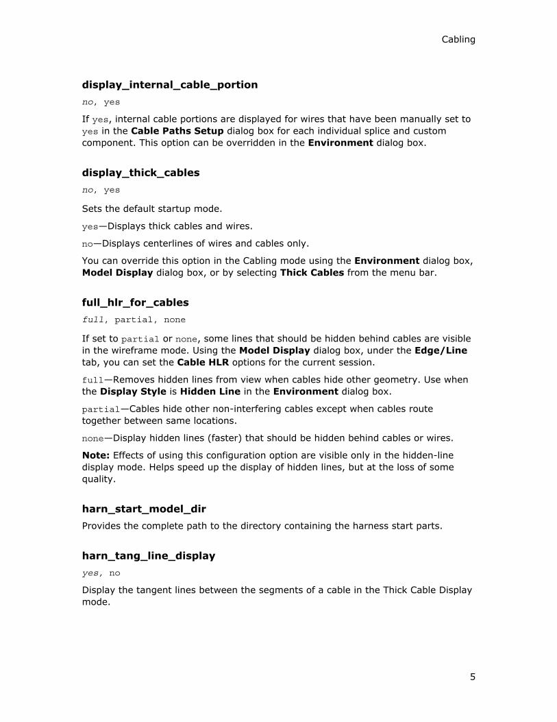
display_internal_cable_portion
no, yes
If yes, internal cable portions are displayed for wires that have been manually set to
yes in the Cable Paths Setup dialog box for each individual splice and custom
component. This option can be overridden in the Environment dialog box.
display_thick_cables
no, yes
Sets the default startup mode.
yes—Displays thick cables and wires.
no—Displays centerlines of wires and cables only.
You can override this option in the Cabling mode using the Environment dialog box,
Model Display dialog box, or by selecting Thick Cables from the menu bar.
full_hlr_for_cables
full, partial, none
If set to partial or none, some lines that should be hidden behind cables are visible
in the wireframe mode. Using the Model Display dialog box, under the Edge/Line
tab, you can set the Cable HLR options for the current session.
full—Removes hidden lines from view when cables hide other geometry. Use when
the Display Style is Hidden Line in the Environment dialog box.
partial—Cables hide other non-interfering cables except when cables route
together between same locations.
none—Display hidden lines (faster) that should be hidden behind cables or wires.
Note: Effects of using this configuration option are visible only in the hidden-line
display mode. Helps speed up the display of hidden lines, but at the loss of some
quality.
harn_start_model_dir
Provides the complete path to the directory containing the harness start parts.
harn_tang_line_display
yes, no
Display the tangent lines between the segments of a cable in the Thick Cable Display
mode.

Cabling - Help Topic Collection
6
multipoint_location_count
1
Specifies the maximum number of cable locations to allow in one feature. To create
locations as features, set this configuration option to 1. To limit the number of
locations in one feature, set to a number between 2 and 100. The suggested number
of locations in one feature must range from 10 to 20. If you set the number of
locations to be greater than 1, then up to the specified number of locations are
created in one feature. Features with multiple locations are automatically created
during routing.
Note: If a single feature has several locations, you can only suppress or reorder
them all together.
pro_spool_dir
<home directory>
Sets the default directory from which the spools are retrieved by default. Use the full
path name, for example: /home/users/spools.
The current working directory is the default directory.
pro_cbltrm_dir
<home directory>
Sets the default directory from which terminators are retrieved by default. Use the
full path name, for example: /home/users/terminators.
The default is the current working directory.
template_harnesspart
inlbs_harn_part.prt, mmns_harn_part.prt
Sets the default template to be used for the harness part model.
inlbs_harn_part.prt—The unit of measure for the harness part model is inches.
mmns_harn_part.prt—The unit of measure for the harness part model is millimeters.
update_pre_16_cable_layers
no, yes
Updates the pre-release 16.0 harnesses.
If yes, automatically updates the harnesses containing cables routed prior to Release
16.0 when retrieved to comply with new display standards.

Cabling
7
Cable-specific Display Setups
About Setting Up the Cabling Display Environment
You can set up the Cabling display environment in the following ways:
• Using the configuration options.
• Using the Environment dialog box.
Use the following options from the Environment dialog box to change the Cabling
display settings:
• Thick Cables or Centerline Cables—Shows cables with true width or as
centerlines. Centerline shows the cable’s centerline with defining location points.
Mass property calculations are performed using the correct thickness regardless
of the display state.
• Internal Cable Portions—Determines if all cable portions inside the splice and
custom components are displayed.
• Reference Designators—Determines if the reference designator for the
component is displayed.
Note: You can also access these options directly from the menu bar.
• Use Fast HLR (Hidden Line Removal)—Displays hidden lines while spinning and
reduces time to compute HLR.
Note: The display style must be set to Hidden Line in the Environment dialog box.
To Display Cables as Thick or Centerline
1. Click Tools > Environment. The Environment dialog box opens.
2. Select either Thick Cables or Centerline Cables.
3. Click Apply and then OK to close the dialog box.
Note: You can also access the Thick Cables, Centerline Cables, and Reference
Designator options directly from the menu bar in the Cabling mode.
or
1. Click View > Display Settings > Model Display. The Model Display dialog
box opens.
2. Click the Edge/Line tab.
3. Under Cable Display, select either Thick Cables or Centerline Cables.
4. Click Apply and then OK to close the dialog box.
Note: To manually route cables, select Centerline Cables.

Cabling - Help Topic Collection
8
Displaying Hidden Lines
Hidden lines are drawn lines that appear behind other objects in a 3D view. When
you set the display style to Hidden Line, the hidden lines appear behind solid
objects, but are displayed in grey. When you set the display style to No Hidden,
lines behind the solid objects are removed from the display.
Cable HLR is available only if the display style is set to Hidden Line in the
Environment dialog box.
The cable is hidden by geometry and can also hide other geometry, depending on
the setting for the FULL_HLR_FOR_CABLES configuration option.
Note: Hidden line display does not always work as expected. In cases where cables
physically intersect a part or another cable, the entire cable may be incorrectly
displayed. This condition indicates cable routing interference.
To reduce cable interference, additional locations can be added. If you use routing
commands,such as Use Dir or Along Axis, greater control is provided over cable
tangency at selected locations and the possibility of interference between cables is
reduced.
Other Cabling Hidden Line Display Options
Use the View > Display Settings > Model Display command to display the hidden
lines of a cable. The following options are available under the Edge/Line tab in the
Cable HLR (Hidden Line Removal) box to display the hidden lines of a cable.
• Full—Cables are hidden by other objects and hide other objects and wires within
harnesses.
• None—Hidden lines are displayed and the overall display process is faster.
Cables are hidden by other objects, but do not hide other objects or hidden
cables within the harness. This is the most recommended method.
• Partial—Similar to Full, but does not perform calculations within the harness.
About Cable Colors
Cable or wire spools contain parameters such as name, type, color, gauge, and so on
for a single insulated conductor. Cable spools contain parameters for a specific
number of conductors and property descriptions for each conductor in the cable.
Using the cable's spool file, you can set a default color for a cable. The value of the
COLOR parameter for a cable or wire specified in the spool file appears in the Color
and Appearance dialog box. Cables can be created using the spool parameters
specified in the cable's spool file. You can retrieve the cable color and appearance
data from the .dmt or .map files.
Note: The .dmt and .map files must exist in the directory from where you start
Pro/ENGINEER. Ensure that the color that you assign to the cable exists in the
color.map file.
If the COLOR parameter for the spool is not defined or if you want to override the
default value of this parameter, use the Color and Appearance dialog box to
Cabling
9
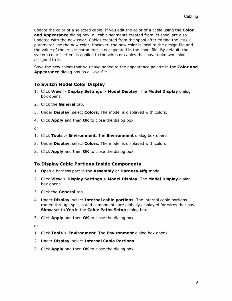
update the color of a selected cable. If you edit the color of a cable using the Color
and Appearance dialog box, all cable segments created from its spool are also
updated with the new color. Cables created from the spool after editing the COLOR
parameter use the new color. However, the new color is local to the design file and
the value of the COLOR parameter is not updated in the spool file. By default, the
system color "Letter" is applied to the wires or cables that have unknown color
assigned to it.
Save the new colors that you have added to the appearance palette in the Color and
Appearance dialog box as a .dmt file.
To Switch Model Color Display
1. Click View > Display Settings > Model Display. The Model Display dialog
box opens.
2. Click the General tab.
3. Under Display, select Colors. The model is displayed with colors.
4. Click Apply and then OK to close the dialog box.
or
1. Click Tools > Environment. The Environment dialog box opens.
2. Under Display, select Colors. The model is displayed with colors
3. Click Apply and then OK to close the dialog box.
To Display Cable Portions Inside Components
1. Open a harness part in the Assembly or Harness-Mfg mode.
2. Click View > Display Settings > Model Display. The Model Display dialog
box opens.
3. Click the General tab.
4. Under Display, select Internal cable portions. The internal cable portions
routed through splices and components are globally displayed for wires that have
Show set to Yes in the Cable Paths Setup dialog box
5. Click Apply and then OK to close the dialog box.
or
1. Click Tools > Environment. The Environment dialog box opens.
2. Under Display, select Internal Cable Portions.
3. Click Apply and then OK to close the dialog box.

Cabling - Help Topic Collection
10
Cabling Drawing Setup Options
Command Description
ref_des_display Sets whether the reference designator is to
be displayed or not:
When set to yes, the reference designator is
displayed on connectors in a cabling or flat
harness assembly. When set to no, the
reference designator is not displayed on the
connectors in the assembly.
show_cbl_term_in_region Allows use of the report symbols
&asm.mbr.name and &asm.mbr.type to show
terminators in Pro/REPORT tables for cable
assemblies having connectors with
terminator parameters.
Shows terminators if set to yes and if the
Cable Info attribute is set for the repeat
region. When creating new drawings, the
default value is yes. For existing drawings,
the default value is no.
Logical Referencing to Diagramming
About Logical Referencing
Use the CABLING > Logical Ref command to reference Diagramming information
directly in Cabling. This information includes the reference designator, pin-to-pin
connection information, and parameter values of connectors, pins, spools, wires, and
cables. You can reference the whole diagram or only items on selected layers. You
can also autoroute wires and cables, and designate connectors.
You can also import the same information from an ASCII text file, either in the PTC
neutral wire list format (.nwf), the Mentor Graphics wire list format, or the Routed
Systems Designer format (.xml). You can use the information to automatically
designate connectors and autoroute complete cables. At any point in the design
process, you can compare logical information with the original wire list or diagram
reference for accuracy. If you change the diagram later, you must run the Logical
Ref command again to update the cabling assembly accordingly.
You must have unique reference designators across the Cabling assembly This is
because you perform a logical referencing operation on the entire assembly and not
specifically with respect to any harness part.
If you export a logical reference, you can write physical data of the wires,
connectors, and components in your assembly to a file, for analysis purposes in other
systems.
On comparing the current logical information with the referenced data, the output
can be displayed on the screen or written to a file.

Cabling
11
You can update the parameter data from the referenced data. All specified spools,
connectors, and wires in the assembly are updated. For example, if you change the
characteristics of a spool in your referenced data, you can automatically update the
information in Cabling using the Update command and selecting the spool from the
list of mismatched objects.
To Reference a Diagram
1. Click CABLING > Logical Ref > Ref Diagram. The Open dialog box opens. The
REF DIAGRAM menu also appears.
2. Choose one of the following REF DIAGRAM commands:
o Full Diagram
o Chosen Layers
By default, you can reference the full diagram.
3. Select a diagram from the Open dialog box and click OK to reference the full
diagram.
4. If you want to logically refer to specific layers in a Diagramming diagram, click
Chosen Layers and select a diagram from the Open dialog box. You must
provide the name of the diagram to be referenced. If no layers are present in the
diagram, Cabling displays an appropriate message. Else, Cabling fetches a
complete list of layers that are available in the referenced diagram and displays
them in the Layer Sel menu.
5. Select one or more layers to be referenced from the list of layers available in the
referenced diagram or select Select All to select all the available layers.
6. Click Done Sel.
Updating Logical References
Use the Update command in the LOGICAL REF menu to update not only the cable
or wire parameters, but also the spool, component, and connector parameters for
any linked logical references.
Note: Prior to using the Update command, ensure that you again logically refer the
diagram in order to get to the latest changes.
About Comparing Data Output
When you compare model data and reference data, a comparison file is generated.
This comparison file lists all the items in both the parameter data and the reference
data. One line is generated for two corresponding items. Additional lines are added if
the parameter data and the reference data do not match.
The object of the comparison such as a wire list or diagram is identified as the
REFERENCE DATA while the active Cabling 3D assembly is identified as the DESIGN
DATA in the INFORMATION WINDOW <assembly_name.cmp> window.

Cabling - Help Topic Collection
12
When you select the Compare command on the LOGICAL REF menu to compare
the design data and the reference data, Pro/ENGINEER compares the following:
• Spools—A match occurs if the design data and the reference data have the same
parameters with the same values. If the parameters common to both the
reference and the design data have the same values, the comparison file
indicates a subset match, denoted by the word subset in parentheses. The
spools are identified by the spool names.
• Connectors and Components—Connectors and components match when they
have the same parameters with the same values. Connectors and components
are identified by their reference designators.
• Wires and Cables—The logical end connections of a wire or cable are matched
and the cable and wire parameters are compared. A wire is said to be matched if
it runs between the same connectors and pins, has the same name, and has the
same parameters with the same values. Wires are identified by the names.
• Nets—If you specify nets separately in the reference information, only their
names are compared and not the wires included in the net. As the wires in the
net do not exist in the logical source, the wires when compared are always
unmatched.
• Cable Conductors—If you specify cable conductors separately in the reference
information, their From/To and parameter information is compared.
You can use the Matched and Alphabetical commands from the LOGICAL REF
menu to display the details of the missing, unmatched, or matched items, in
alphabetical order.
The Neutral Format Wire List
NEW CONNECTOR T2
PARAMETER MODEL_NAME CLEANCONN2
PARAMETER NUM_OF_PINS 4
PARAMETER GENDER MALE
PIN 1
PARAMETER ENTRY_PORT sys1
PARAMETER GROUPING ROUND
PARAMETER INTERNAL_LEN 0
PIN 2
PARAMETER ENTRY_PORT sys2
PARAMETER GROUPING ROUND
PARAMETER INTERNAL_LEN 0

Cabling
13
PIN 3
PARAMETER ENTRY_PORT sys3
PARAMETER GROUPING ROUND
PARAMETER INTERNAL_LEN 0
PIN 4
PARAMETER ENTRY_PORT sys4
PARAMETER GROUPING ROUND
PARAMETER INTERNAL_LEN 0
! Rails
! Wires and cables
NEW CABLE CABLE0002 F_SPOOL
ATTACH T1 "" T2 ""
CONDUCTOR 4
ATTACH T1 4 T2 4
PARAMETER NAME WIRE4
CONDUCTOR 3
ATTACH T1 3 T2 3
PARAMETER NAME WIRE3
CONDUCTOR 2
ATTACH T1 2 T2 2
PARAMETER NAME WIRE2
CONDUCTOR 1
ATTACH T1 1 T2 1
PARAMETER NAME WIRE1
! comment
NEW WIRE_SPOOL <wire spool name>
PARAMETER <param> <value>
PARAMETERS <param1> <param2> <param3>
VALUES<param1 val> <param2 val> <param3 val>
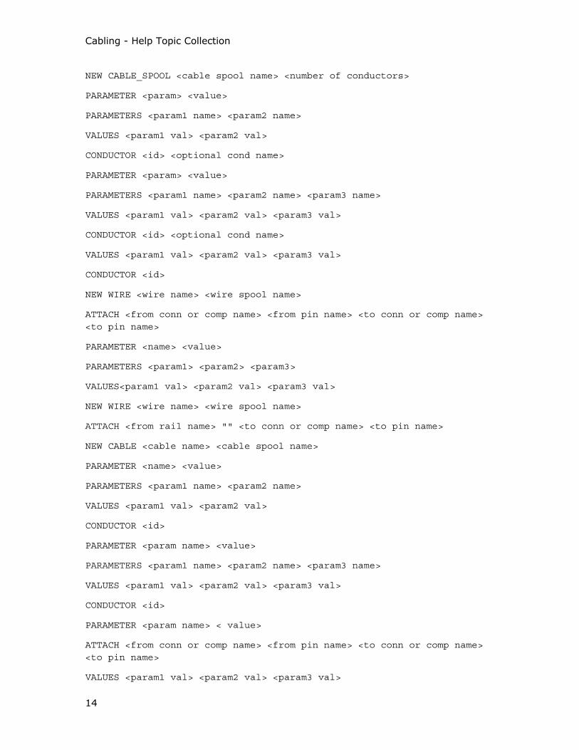
Cabling - Help Topic Collection
14
NEW CABLE_SPOOL <cable spool name> <number of conductors>
PARAMETER <param> <value>
PARAMETERS <param1 name> <param2 name>
VALUES <param1 val> <param2 val>
CONDUCTOR <id> <optional cond name>
PARAMETER <param> <value>
PARAMETERS <param1 name> <param2 name> <param3 name>
VALUES <param1 val> <param2 val> <param3 val>
CONDUCTOR <id> <optional cond name>
VALUES <param1 val> <param2 val> <param3 val>
CONDUCTOR <id>
NEW WIRE <wire name> <wire spool name>
ATTACH <from conn or comp name> <from pin name> <to conn or comp name> <to pin name>
PARAMETER <name> <value>
PARAMETERS <param1> <param2> <param3>
VALUES<param1 val> <param2 val> <param3 val>
NEW WIRE <wire name> <wire spool name>
ATTACH <from rail name> "" <to conn or comp name> <to pin name>
NEW CABLE <cable name> <cable spool name>
PARAMETER <name> <value>
PARAMETERS <param1 name> <param2 name>
VALUES <param1 val> <param2 val>
CONDUCTOR <id>
PARAMETER <param name> <value>
PARAMETERS <param1 name> <param2 name> <param3 name>
VALUES <param1 val> <param2 val> <param3 val>
CONDUCTOR <id>
PARAMETER <param name> < value>
ATTACH <from conn or comp name> <from pin name> <to conn or comp name> <to pin name>
VALUES <param1 val> <param2 val> <param3 val>

Cabling
15
NEW CONNECTOR <name>
PARAMETER <param> <value>
PARAMETERS <param1 name> <param2 name>
VALUES <param1 val> <param2 val>
PIN <pin name>
PARAMETERS <param1 name> <param2 name>
VALUES <param1 val> <param2 val>
PIN <pin name>
PARAMETER <name> <value>
PARAMETERS <param1 name> <param2 name>
VALUES <param1 val> <param2 val>
PIN <pin name>
PIN <pin name>
VALUES <param1 val> <param2 val>
NEW COMPONENT <name>
PARAMETER <name> <value>
PARAMETERS <param1 name> <param2 name>
VALUES <param1 val> <param2 val>
PIN <pin name>
PARAMETERS <param1 name> <param2 name>
VALUES <param1 val> <param2 val>
PIN <pin name>
PARAMETERS <param1 name> <param2 name>
PARAMETER <name> <value>
VALUES <param1 val> <param2 val>
PIN <pin name>
VALUES <param1 val> <param2 val>
NEW RAIL <name>
PARAMETER <param name> <param value>
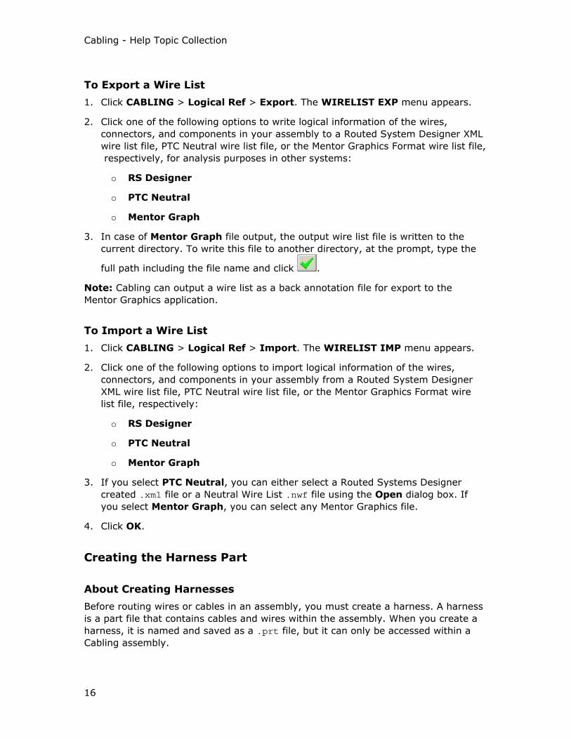
Cabling - Help Topic Collection
16
To Export a Wire List
1. Click CABLING > Logical Ref > Export. The WIRELIST EXP menu appears.
2. Click one of the following options to write logical information of the wires,
connectors, and components in your assembly to a Routed System Designer XML
wire list file, PTC Neutral wire list file, or the Mentor Graphics Format wire list file,
respectively, for analysis purposes in other systems:
o RS Designer
o PTC Neutral
o Mentor Graph
3. In case of Mentor Graph file output, the output wire list file is written to the
current directory. To write this file to another directory, at the prompt, type the
full path including the file name and click .
Note: Cabling can output a wire list as a back annotation file for export to the
Mentor Graphics application.
To Import a Wire List
1. Click CABLING > Logical Ref > Import. The WIRELIST IMP menu appears.
2. Click one of the following options to import logical information of the wires,
connectors, and components in your assembly from a Routed System Designer
XML wire list file, PTC Neutral wire list file, or the Mentor Graphics Format wire
list file, respectively:
o RS Designer
o PTC Neutral
o Mentor Graph
3. If you select PTC Neutral, you can either select a Routed Systems Designer
created .xml file or a Neutral Wire List .nwf file using the Open dialog box. If
you select Mentor Graph, you can select any Mentor Graphics file.
4. Click OK.
Creating the Harness Part
About Creating Harnesses
Before routing wires or cables in an assembly, you must create a harness. A harness
is a part file that contains cables and wires within the assembly. When you create a
harness, it is named and saved as a .prt file, but it can only be accessed within a
Cabling assembly.

Cabling
17
However, a harness part can only be accessed in Assembly mode and cannot be
opened in Part mode. You can output a harness to a drawing view: by selecting a
harness part and setting it as the active model using Set Model or by selecting a flat
harness.
You can create several harnesses in the same assembly. In assemblies with multiple
harnesses, you can work on only one harness part at a time. The name of the active
harness is displayed below the assembly name in the graphics window, with the label
WORK HARNESS. While this harness is active, every feature you add to the cabling is
added to the active harness part. You can select cabling entities that have been
added to other harnesses only when the respective harness is active.
To organize a large design, you can divide the harness into subharnesses. A
subharness is a subset of a harness part and not a separate file. Subharnesses can
use all the entities available to a harness, but you can also create them separately in
Harness Manufacturing mode.
Use the CABLING > Set Up command to create and edit harness parameters,
names, notes, and reference dimensions.
To Create a Harness
1. Click CABLING > Harness > Create. The New dialog box opens.
By default, under Type, Part and under Sub-type, Harness are selected.
Note: The other options on the New dialog box are not available.
2. In the Name box, type a name for the new harness part.
3. If you want to use the default template, click OK. Pro/ENGINEER opens a new
harness part.
Note: Specify the default template using the template_harnesspart
configuration option.
If you want to use a custom template,
a. Clear the Use default template check box and click OK. The New File
Options dialog box opens.
b. Browse to the desired template. Click OK.
The template file is assigned and Pro/ENGINEER opens a new harness part. The
newly created harness becomes the active harness.
To Modify a Harness
1. Ensure that a harness is active.
2. Click CABLING > Set Up. The HARN SETUP menu appears.
3. Edit units of measure, harness names, report definitions, notes, parameters,
terminator tables, or strip tables. Changes affect only the active harness part.
4. Click Done.

Cabling - Help Topic Collection
18
Using the Harn Setup Menu
You can specify the following options to modify a harness:
• Units—Determines the length of the harness in units.
• Name—Sets up a name for the harness. The NAME SETUP menu appears:
o Component
o Feature
o Detail Item
o Other
• Report Defs—Sets default values for cable type locations as From/To in report
tables.
o Cable Jacket
o Cable Shield
o Cable Pin
o Show Current
o Notes—Modifies, adds, or removes notes from a cabling assembly.
o Parameters—Sets up parameters for the harness.
o Term Table—Accesses terminator table operations.
o Strip Table—Accesses strip table operations.
To Delete a Harness
1. Select the harness part to be deleted from the assembly or from the model tree.
2. Click Edit > Delete. The harness part is removed from the assembly and all
cabling data in the harness part is lost.
Note: Use the Delete command only when you want to completely remove a
harness and start over or if you have created a harness part and never used it. If
you do not delete a harness part, it appears as a part in the Bill of Materials.
To Set the Working Harness
1. Click Cabling > Harness. The HARNESSES menu appears.
2. Select the harness name you want to set as the working or active harness.
To Copy a Harness
1. Click CABLING > Harness > Copy Harness. The Open dialog box opens.
2. Select the harness that you want to copy and click Open. The Open Rep dialog
box opens.
Cabling
19
3. Select the required representation and click OK. The selected harness with its
corresponding assembly is displayed in a separate window.
The Copy Harness dialog box opens and the Select menu appears.
4. Select a connector in an assembly to which you want to copy the harness
corresponding to the reference designator of the component or connector in the
assembly from which the harness is being copied.
A new reference designator is assigned to the reference model.
5. Once you have selected all connectors, specify a new harness name in the Copy
Harness dialog box and click OK.
The harness is copied to the assembly.
To Create Datum Features for Harness Parts
1. Click Insert > Model Datum.
2. All datum features support harness design. Click an appropriate command from
the following to specify the datum types.
o Plane
o Axis
o Point
o Coordinate System
o Default Coordinate System
o Sketched Curve
o Curve
Refer to the Part Modeling module for details on how to create different datum
features.
To Create Subharnesses
1. Click CABLING > Harness > Create. You are prompted to name a harness.
2. Do not type a name. Click to cancel. The SUBHARNESS menu appears.
3. Click Setup > Add.
4. At the prompt, type a new name for the subharness.
To Set the Default Subharness
1. Click CABLING > Harness > Create. You are prompted to name a harness
name.

Cabling - Help Topic Collection
20
2. Do not type a name. Click to cancel. The SUBHARNESS menu appears.
3. Click Set Default.
4. Select the name of the subharness that you want to set as the default
subharness.
Defining Report Object Names
Use the CABLING > Set Up > Report Defs command to assign names to the
following objects for use in Pro/REPORT:
• Cable Jacket—Name for unshielded cable type locations
• Cable Shield—Name for shielded cable type locations
• Cable Pin—Pin name for cable type locations
Clicking Show Current displays the currently assigned objects.
Adding Harnesses to a Family Table
About Adding Harnesses to a Family Table
When you add a family table to a part, the part is first opened in the Part mode
before the creation of part instances. If you choose the parent assembly as the
reference model, it is added as a reference to the base part object in the part family
table.
The assembly instance in the assembly family table is modified to include the part
instance. For more information on family tables, refer to Managing Model
Composition under Pro/ENGINEER Fundamentals.
To Add a Harness Part to a Family Table
1. After you set the working harness, click CABLING > Family Tab. The Family
Table : <harness_name> dialog box opens.
2. Click to add or delete table columns. The Family Items, Generic
:<harness name> dialog box opens. You can add dimensions, parameters,
features, components, groups, a feature from a table driven pattern, a merged
part, or a referenced model to the family table.
3. Under Add Item, you can select Ref Model. The REFERENCES menu appears
with a list of available reference models.
4. Select a reference assembly from the list and click DONE.
5. Click OK in the Family Items, Generic :<harness name> dialog box.
6. If you do not want to add more reference models to the family table, click OK in
the Family Table <harness_name> dialog box.

Cabling
21
To Use Family Tables with Harnesses
1. Click Applications > Standard.
2. Click Tools > Family Tab. The Family Table <assembly_name> dialog box
opens.
3. Add a family table to the parent assembly.
4. Click to create an instance of a part by opening it in the Part mode.
5. When you have completed adding the required number of instances, click OK.
You can modify the assembly instance in the assembly family table to include the
harness part instance.
Creating Spools
About Spools
A spool has a unique set of parameters and values that are passed to the wire or
cable when a wire or cable is created. Each wire and cable in the design must be
created from a predefined spool. The spool, when defined, is saved within the
assembly and can be written to a text file with the .spl extension. You can reference
this file in a new diagram or cabling designs.
The types of spools are:
• Wire spools—You must set wire spool parameters such as NAME and TYPE. The
name of the wire spool must be unique. The TYPE parameter is set to WIRE to
differentiate it from a cable spool. Other common but optional parameters
defined in the wire spool are COLOR and WIRE_GAUGE. The parameter,
MIN_BEND_RADIUS is automatically generated. This parameter provides values for
calculations in Harness Design.
• Cable spools—Cable spools have parameters that are similar to those required
for wire spools. You must set the NUM_CONDUCTORS parameter to define the
number of insulated conductors in the cables that are created from the spool.
Assign an appropriate integer value to the NUM_CONDUCTORS parameter.
• Sheath spools—Sheath spools are created for bundles. You must set the sheath
spool parameters such as SHEATH_TYPE and PRESHRINK_INNER_DIAMETER. Other
common parameters are NAME , TYPE, and UNITS. The parameters,
MIN_BEND_RADIUS and WALL_THICKNESS are automatically generated.
Note:
• Setting the pro_spool_dir configuration option allows you to specify a directory
from which spools can be read. If you do not specify a directory, the current
working directory is the default.
• You can retrieve the spool parameters using the Pro/REPORT table and also use
these parameters to display the wire or cable labels.

Cabling - Help Topic Collection
22
• If you create spool files in a text editor outside of Pro/ENGINEER, the name of
the spool file must be identical to the spool name in Pro/ENGINEER. You can also
save a spool file in the ASCII format to be retrieved for use in other diagrams or
a Cabling assembly.
Spool Parameters
SPOOL PARAMETER DESCRIPTION
COLOR Establishes the color of the cable, wire insulation,
or sheathing. Defaults are provided through
Pro/TABLE Help, but the setting can be any single
string, such as Brown/Orange.
Format: COLOR color_name
Example: COLOR red_and_yellow_stripe
Note: This color is not automatically applied to
the cable, wire, or bundle.
COLOR_CODE As a text string, establishes the code of the color,
such as a part number.
Format: COLOR_CODE text_string
Example: COLOR_CODE r14
DENSITY Linear density, mass per unit length. The
MASS_UNITS and UNITS parameters should also
be specified for the wire/cable or sheath. Default
units for this value are derived from the assembly
itself if the MASS_UNITS and UNITS parameters
are not used.
Format: DENSITY value
Example: DENSITY 36
INSUL_TYPE
(NOT VALID FOR
SHEATH SPOOLS)
As a text string describes the insulation type, such
as, fiber, teflon, tefzel. Default is none.
Format: INSUL_TYPE text_string
Example: INSUL_TYPE teflon

Cabling
23
SPOOL PARAMETER DESCRIPTION
LINESTYLE Changes the line style for cable or sheath spools.
If this parameter is set for a sheath spool, it is
overridden by any linestyles assigned to a bundle.
The following line styles are permitted:
SOLID FONT (default), DOTFONT, CTRLFONT,
PHANTOMFONT, DASHFONT, CTRLFONT_S_L,
CTRLFONT_L_L, CTRLFONT_S_S
Format: LINE STYLE style
Example: LINE STYLE dotfont
MASS_UNITS The mass units of the cable, wire, or sheath. For
example, Ounce, Pound, Kilogram. Should be used
if the DENSITY parameter is used.
Format: MASS_UNITS value
Example: MASS_UNITS lb
MIN_BEND_RADIUS
(NOT REQUIRED FOR
TAPE SHEATH SPOOLS)
Sets the minimum bend radius that the cable or
sheath can take as it is routed. If this radius is
violated during routing, the cable location is not
created. When used in a sheath spool, this value
is used along with the minimum bend radii of the
components in the bundle in calculating the actual
minimum bend radius used for the bundle. When
used with the DEFINE and ENDDEF cable spool
parameters to define a conductor, the value of
this parameter overrides the
DEFAULT_COND_BEND_RAD parameter value.
Format: MIN_BEND_RADIUS value
Example: MIN_BEND_RADIUS 2.5
NAME Name entered when creating the spool. It is read
only.

Cabling - Help Topic Collection
24
SPOOL PARAMETER DESCRIPTION
THICKNESS
(NOT VALID FOR
SHEATH SPOOLS)
Diameter of the cable of WIRE or ROUND type,
thickness of the cable for FLAT type. This value is
used to offset the cable centerline from surfaces
when the location is placed. When used with the
DEFINE and ENDDEF cable spool parameters to
define a conductor, the value of this parameter
overrides the DEFAULT_COND_THICKNESS
parameter value. If you modify the thickness
later, you must modify each location with an
offset to account for the change.
Format: THICKNESS value
Example: THICKNESS 0.25
TYPE When you edit spool parameters, the value of the
TYPE parameter indicates the type of spool being
edited. For example, this parameter specifies
whether the spool is a pre-fabricated cable spool
(PREFAB), wire spool (WIRE), or sheathing spool
(SHEATH). The value of this parameter is read
only.
Format: TYPE value
Example: TYPE prefab
Cable Spool Specific Parameters
The following is a list of predefined parameters that are unique to cable spools. A
cable has a defined number of conductors, and each conductor has its own defining
parameters, for example gauge or color, within the spool file. All wire spool
parameters are valid for cable spools. Required parameters are shown in bold.
CABLE SPOOL SPECIFIC
PARAMETER
DESCRIPTION
NAME The name of the spool file.
Format: NAME text_string
TYPE (read only) Determines a cable spool or wire
spool. Cables are of type PREFAB.

Cabling
25
CABLE SPOOL SPECIFIC
PARAMETER
DESCRIPTION
DEFAULT_COND_BEND_RAD Sets the default minimum bend
radius for all conductors in the
cable. The value of this parameter
can be overridden by specifying a
value for the MIN_BEND_RADIUS
spool parameter in the conductor
definition.
Format:DEFAULT_COND_BEND_RAD
value
Example:
DEFAULT_COND_BEND_RAD 0.25
DEFAULT_COND_THICKNESS Sets the default thickness for all
conductors in a cable. The value of
this parameter can be overridden by
specifying a value for the
THICKNESS spool parameter in the
conductor definition.
Format:
DEFAULT_COND_THICKNESS value
Example:
DEFAULT_COND_THICKNESS 0.75
NUM_CONDUCTORS The total number of conductors
present in a cable. The default value
is zero.
Format: NUM_CONDUCTORS value
Example: NUM_CONDUCTORS 3
DENSITY The linear density of the spool (in
mass/unit length). Not used in
Diagramming, but used in Cabling
when referencing a diagram to
determine Mass Properties.
INSUL_TYPE Insulation type. (Text string) NONE
is the default
SHIELD_TYPE
(cable spools only)
A text string indicating cable shield
type.
Format: SHIELD_TYPE text_string
Example: SHIELD_TYPE aluminum

Cabling - Help Topic Collection
26
CABLE SPOOL SPECIFIC
PARAMETER
DESCRIPTION
CABLE_JACKET_REPORT_NAME Use the default value DEFAULT, in
which case the name of the cable
shows in the report table. Any other
value is interpreted as plain text.
For example, &cable_name has no
special meaning.
CABLE_SHIELD_REPORT_NAME Use this name for the cable symbol
if the cable is shielded.
CABLE_NODE_REPORT_NAME Use this name for the nodes of a
cable symbol. The default value is "-
".
SHIELD_LINEAR_RESISTANCE Specifies linear resistance of the
wire's shielding.
OUTER_SHIELD_LINEAR_RESISTANCE Specifies linear resistance of the
wire's outer shielding.
LIN_CAP_TO_ITEM Specifies linear electric capacity
between items.
LIN_CAP_ITEM_TO_SHIELD Specifies linear electric capacity
between items and shield.
LIN_CAP_ASSEM_ITEM_TO_SHIELD Specifies linear electric capacity
between assembly items and shield.
OUTER_SHIELD_THICKNESS Specifies thickness of the outer
shielding of the wire.

Cabling
27
Conductor Parameters
CONDUCTOR
PARAMETER
DESCRIPTION
NAME Used to assign unique names to individual
conductors in a cable. This parameter is used in
conjunction with the DEFINE and ENDDEF cable
spool parameters to specify a name for the
conductor being defined. The name assigned to a
cable conductor must be unique within the spool,
but the same conductor name can be used in
multiple spools. If the WIRE_COND cable
parameter is present, use that name instead of the
name specified with this parameter. Format: NAME
string
Example: NAME blue_cond
WIRE_CONSTRUCTION As a text string indicates wire construction,that is,
solid, stranded, and so on.
Format: WIRE_CONSTRUCTION text_string
Example: WIRE_CONSTRUCTION stranded
WIRE_GAUGE As a text string indicates wire gauge.
Format: WIRE_GAUGE text_string
Example: WIRE_GAUGE 18
Sheath Spool Parameters
SHEATH SPOOL PARAMETER DESCRIPTION
OUTER_DIAMETER
(REQUIRED ONLY FOR TUBE
SHEATH TYPE)
Indicates the outer diameter of the tube
sheathing. The units used are specified by
the UNITS parameter.
Format: OUTER_DIAMETER value
Example: OUTER_DIAMETER 3

Cabling - Help Topic Collection
28
SHEATH SPOOL PARAMETER DESCRIPTION
PRESHRINK_INNER_DIAMETER
(USED ONLY FOR SHRINK
SHEATH TYPE)
Indicates the pre-shrunk diameter of
SHRINK sheathing. This value specifies the
inner diameter only and allows the system
to check interference between the shrink
sheathing itself and the wires, cables, and
bundles within it. The thickness of
sheathing is specified by the parameter
WALL_THICKNESS. A value of 0 (default)
forces the SYSTEM to NOT check for any
interference.
Format: PRESHRINK_INNER_DIAMETER
value
Example: PRESHRINK_INNER_DIAMETER
0.5
SHEATH_TYPE Specifies the type of sheathing for this
spool. Valid values are TAPE, TUBE, and
SHRINK
Format: SHEATH_TYPE value
Example: SHEATH_TYPE TAPE
WALL_THICKNESS Indicates the thickness of the sheathing.
The units used are specified by the UNITS
parameter.
Format: WALL_THICKNESS value
Example: WALL_THICKNESS 0.75
WIDTH Specifies the tape width for tape sheathing.
Format: WIDTH value
Example: WIDTH 0.56
To Create a Spool
1. Click CABLING > Spools > Create. The CREATE SPOOL menu appears.
2. Select one of the following filters to specify the type of spool that you want to
create.
o Wire—Creates a wire spool.
o Cable—Creates a pre-fabricated cable spool.
o Sheath—Creates a sheath spool. Sheath spools are referenced by bundles.

Cabling
29
o From Logical—Creates a spool using a logical reference. The REF SPOOL
menu appears.
Select the required spools from the list and click Done Sel to copy spool
parameters from the referenced diagram. You can select one or more wire
or cable spool names from the list or click Select All to select all the
available spools.
Note: If the logical data is imported from a wire list, the From Logical
command is available for wire creation only. This is because the imported
wire list format does not support cables.
If you use CABLING > Spools > Create > From Logical, Cabling automatically
creates all spools associated with the created cables and wires. The information
that is used to create these spools is taken from the logically referenced data
from which the wires and cables were created.
If the cabling assembly does not have a reference to a diagram or a wire list,
select a spool from which the cable or wire draws its characteristics.
3. To create a new spool for a wire, cable, or sheath, at the prompt, type a new
spool name and press ENTER. The Electrical Parameters dialog box opens.
4. Under Display For, select Connections to add parameters to wires or cables or
Conductors to add parameters to conductors of a cable spool.
5. If you have selected Conductors, select a parameter in the NUM_CONDUCTORS
column, specify a value for the number of conductors for a cable spool in the
Value box, and click Apply.
6. Click View > Columns . The Model Tree Columns dialog box opens.
7. Add the required parameters to the spool, click Apply, and then OK.
8. When finished, click File > Save or File > Save As to save the file to disk.
9. Click OK to apply the spool parameters.
To Modify Spools
1. Click CABLING > Spools > Edit. The Select Spools dialog box opens.
2. Select one of the following filter to specify the type of spool to be modified:
o All Spools
o Wire Spools
o Cable Spools
o Cable Spools by Num Cond

Cabling - Help Topic Collection
30
3. Click a spool name from the spool list. You can filter the spools by spool type or
number of conductors.
or
Click or to select or remove all spools from the list, respectively.
4. Click OK. The Electrical Parameters dialog box opens.
5. Modify the required spool parameters, click Apply, and then OK.
6. Click Done/Return in the SPOOLS menu.
Note:
• Use CABLING > Spools > Read to read in spool parameter data from a
previously created spool that was saved to disk. This file must have a .spl
extension.
• Use CABLING > Spools > Write to write the selected spool parameter data to
your current directory. These files have a .spl extension.
To Rename Spools
1. Click CABLING > Spools > Rename. The Select Spools dialog box opens.
2. Select one of the following filters to specify the type of spool to be modified:
o All Spools
o Wire Spools
o Cable Spools
o Cable Spools by Num Cond
3. Click a spool name from the spool list. You can filter the spools by spool type or
number of conductors.
4. Click OK in the Select Spools dialog box. You are prompted for a new spool
name.
5. At the prompt, type a new spool name and press ENTER. The spool is renamed.
6. Click Done/Return in the SPOOLS menu.
Note: If you have renamed spools using the Select Spools dialog box, all wires or
cables in the Cabling assembly reference the renamed spool. If the assembly
logically references a diagram, then renaming a spool in the diagram and updating
the logical reference also causes the corresponding spools in the assembly to be
renamed. Use CABLING > Logical Ref > Update to overwrite the existing cabling
spool parameters with the modified spool parameters of the logically referenced
diagram.

Cabling
31
In a comparison between an assembly and a logically referenced diagram, if a spool
in the assembly has the same parameter values as the spool in the logically
referenced diagram, then both these spools are recognized to be the same.
To Write Spools
1. Click CABLING > Spools > Write. The Select Spools dialog box opens.
2. Select one of the following filters to specify the type of spool to be modified:
o All Spools
o Wire Spools
o Cable Spools
o Cable Spools by Num Cond
3. Click a spool name from the spool list. You can filter the spools by spool type or
number of conductors.
4. Click OK. The selected spool file is output to the directory from where you started
the Pro/ENGINEER session or to the Spool Dir directory, if you have set the
pro_spool_dir configuration option.
To Remove Spools
1. Click CABLING > Spools > Remove. The Select Spools dialog box opens.
2. Select one of the following to specify the type of spool to be modified:
o All Spools
o Wire Spools
o Cable Spools
o Cable Spools by Num Cond
3. Click a spool name from the spool list. You can filter the spools by spool type or
number of conductors.
or
Click or to select or remove all spools from the list, respectively.
4. Click OK. If the spool has cables referencing to it, you are prompted to confirm
the deletion.
5. Click Yes at the prompt, the selected spools are deleted successfully.
Cabling - Help Topic Collection
32
To List Spools
1. Click CABLING > Spools > List to view the list of spools in the diagram or
cabling assembly. The INFORMATION WINDOW opens listing the spools and
the spool type.
2. Click File > Save As to save the spool information to the required location.
3. Click Close to close the INFORMATION WINDOW.
Modifying Spool Color
If you set the COLOR parameter of a spool to a color that is available in the
color.map file or one that was created and named in the Appearance Editor dialog
box, all cables or wires created from this spool are created with the specified color. If
you change the value of the COLOR parameter and regenerate the model, the color is
replaced with the new color. You can change the color of a cable in the design
without editing the spool. Use the Appearance Editor dialog box to set a color for
the cables without editing the spool. All the segments of the selected cable take the
new color. Any new segments you create for this cable after setting a new color will
use the new color. However, the spool remains unedited. The COLOR value for the
spool is overridden at the design level.
To Add Spools from a Logical Reference
1. Click CABLING > Logical Ref > Ref Diagram to reference Diagramming
information directly in Cabling. This information includes the reference
designator, pin-to-pin connection information, and parameter values of
connectors, pins, spools, wires, and cables.
2. Click CABLING > Spools > Create > From Logical. The REF SPOOL menu
appears.
3. Select the spools that you want to add to the cabling file or click Select All to
add all spools.
4. Click Done Sel.
Note: If you use From Logical, Cabling automatically creates all spools associated
with the created cables and wires. The information used to create these spools is
taken from the logically referenced data from which the wires were created.
Adding Wires and Cables
About Wires and Cables
A wire has one conductor. When wires or cables are first created, only the name and
a set of default parameters inherited from the spool are present for the wire or cable.
Later, you can add additional features or parameters to further define the physical
shape of the connection. The wires or cables in the database must also be named
and defined before you route them.

Cabling
33
Spools contain physical properties and a set of parameters for the cables or wires
that can be reused as needed, the same way as the length of a reel wire is rolled off
a reel spool. You can import wires, cables, and spools from Diagramming or create
them within the Cabling assembly.
Cable and Wire Parameters
CABLE OR WIRE
PARAMETER
DESCRIPTION
END_TYPE Specifies the location of the origin or destination
of a wire or cable.
Format: END_TYPE ref_des entry_port direction
The value of direction indicates whether the wire
or cable is routed from the entry port or to the
entry port. Valid values for direction are from and
to.
Example: END_TYPE j16 entry _1 from
Two END_TYPE statements are required for each
wire or cable: one indicates the origin while the
other indicates the destination. These statement
are automatically created when the wire or cable
has been routed. Only the value of direction can
be modified without re-routing the wire or cable.
MAX_ALLOWED_LENGTH Defines the maximum permitted length. For
example to avoid signal degradation.
Format: MAX_ALLOWED_LENGTH value
Example: MAX_ALLOWED_LENGTH 60
MIN_ALLOWED_DIST Minimum permitted distance between parallel
conductors that avoids interference.
Format: MIN_ALLOWED_DIST value
Example: MIN_ALLOWED_DIST 2
NAME Name entered when you create the cable. You
can change the cable name by editing this
parameter.
Format: NAME text_string
Example: NAME cabl

Cabling - Help Topic Collection
34
CABLE OR WIRE
PARAMETER
DESCRIPTION
SPOOL The name of the spool which the cable or wire
references. You can modify the spool name by
editing this parameter. This is a required
parameter.
Format: SPOOL text string
Example: SPOOL spll8red
STRIP_LENGTH Specifies the strip length of the wire or cable.
Format: STRIP_LENGTH wire_name strip_length
dir auto_assign
Where strip_length specifies the amount of wire
that should be stripped, dir specifies the
directional end of the routed wire according to the
END_TYPE parameter, and auto_assign
determines if the strip information is to be
derived from a Strip Length Table. Valid values of
auto_assign are true and false.
For cable, it is the conductor name or cable name
instead of wire name.
Example: STRIP_LENGTH W0030 0.25 FROM
TRUE
TARGET_LENGTH Sets the desired length for the cable after finished
routing. Can be used when cable is most
conveniently purchased in specific lengths, or
when a cable is designed to be a certain length,
such as for radio antenna leads.
Format: TARGET_LENGTH value
Example: TARGET_LENGTH 24
USER_DEFINED Any user defined parameter can be added with
this format.
Format: Parameter_name value
Example: VENDOR kga_electric_supply

Cabling
35
The parameter that can be associated with Cable feature only is:
PARAMETER DESCRIPTION
WlRE_COND This parameter defines wire names of conductors in
a cable. This parameter takes precedence over the
NAME cable spool parameter.
Format: WIRE_COND new_wire_name conductor#
Example: WIRE_COND W3 2
Assigns wire name W3 to conductor 2.
To Create a Wire or Cable
1. After creating or activating a harness part, click CABLING > Feature > Create.
The CABLE FEAT menu appears.
2. Click Cable to create a cable or Wire to create a wire and associate parameters
with it. If the assembly has no reference to a diagram, you are prompted to
specify a new cable name. The SPOOL NAMES menu appears.
3. Select an existing spool from which the cable or wire draws its characteristics or
create a new spool. A new wire or cable is created.
4. Click Done/Return in the CABLE FEAT menu.
To Add a Wire or Cable to the Database by Reference
1. After creating or activating a harness part, click CABLING > Feature > Create.
The CABLE FEAT menu appears.
2. Click Cable to create a cable or Wire to create a wire and associate parameters
with it. If the assembly has a reference to a diagram, the CREATE CBL menu
appears.
3. Click From Logical, select one or more wire or cable names from a list of names
generated from the diagram or wire list displayed in the REF CABLE menu, and
click Done Sel to select the referenced cable or wire.
or
Click Enter Name to create a cable or wire without using referenced information
from a diagram or wire list and type a name for the cable or wire when
prompted.
Note: If the logical data is imported from a wire list, the From Logical command
is available for wire creation only. This is because the imported wire list format
does not support cables.
4. Click Done/Return in the CABLE FEAT menu.

Cabling - Help Topic Collection
36
To Modify Cables and Wires
1. Click CABLING > Modify to edit dimensions, parameters, lengths, or locations of
cables and wires. The MOD CABLE menu appears.
2. Click one of the following commands to modify cables or wires:
o Mod Dim—Modifies the values of cable dimensions.
o Parameters—Modifies parameters of a cable, wires, or bundle for selected
cables, wires, or bundles through the Electrical Parameters dialog box.
o Length—Allows you to access commands to measure any continuous
portion of the selected cable or to fix the length of cable between locations.
o Split Cable—Creates a new cable or bundle by splitting the existing cable
or bundle into two parts.
o Mod Bundle—Adds or deletes cables or wires from a bundle.
o Cosmetics—Modifies tiewrap, tape, and marker features through the
Electrical Parameters dialog box.
About Strip Length Table
A strip length table automatically assigns wire strip information to wires in a cabling
assembly. The strip length table is similar to a terminator table.
The first column of the table must contain the required strip length of a conductor.
By default, the second column specifies the terminator whose connected wire is
stripped. You can modify this value.
As in terminator tables, the valid objects are COND, SPOOL, CONN, or PIN. Items
specified in the parameter heading can be any parameter from the object heading
above it. An asterisk (*) indicates that it applies to all values for the specified
parameters.
Wire Strip Information
Use the STRIP_LENGTH parameter to specify the amount of insulation to be stripped
off from the end of the wire. The STRIP_LENGTH parameter specifies the name of the
wire to be stripped, the amount of insulation to be removed from the wire, and the
end of the wire to be stripped.
You can use a strip length table to automatically assign strip lengths in a batch
process.
To Create a Strip Length Table
1. Click CABLING > Set Up > Strip Table. The Strip Table dialog box opens.
2. Click in a cell in the COND STRIP_LENGTH column and click Insert > Insert
Row After. A new row is added to the table.
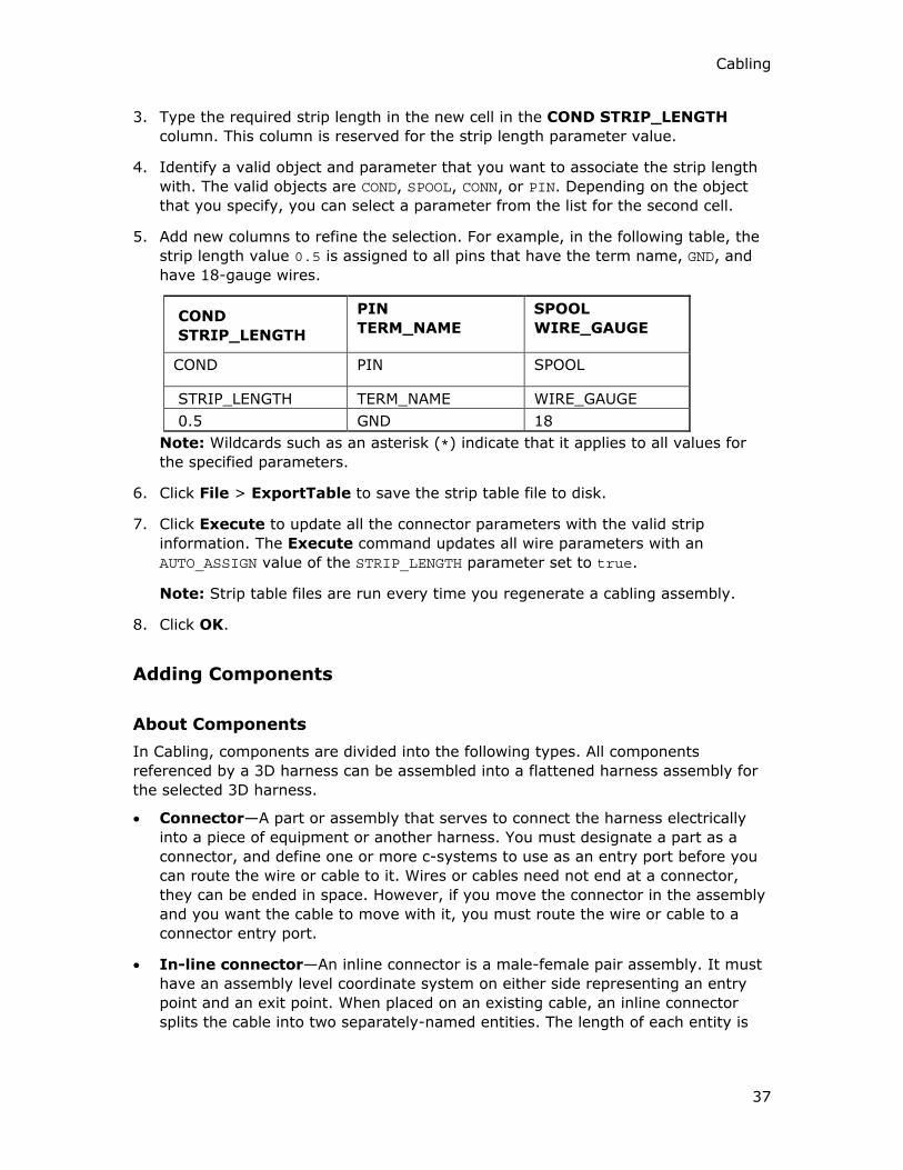
Cabling
37
3. Type the required strip length in the new cell in the COND STRIP_LENGTH
column. This column is reserved for the strip length parameter value.
4. Identify a valid object and parameter that you want to associate the strip length
with. The valid objects are COND, SPOOL, CONN, or PIN. Depending on the object
that you specify, you can select a parameter from the list for the second cell.
5. Add new columns to refine the selection. For example, in the following table, the
strip length value 0.5 is assigned to all pins that have the term name, GND, and
have 18-gauge wires.
COND
STRIP_LENGTH
PIN
TERM_NAME
SPOOL
WIRE_GAUGE
COND PIN SPOOL
STRIP_LENGTH TERM_NAME WIRE_GAUGE
0.5 GND 18
Note: Wildcards such as an asterisk (*) indicate that it applies to all values for
the specified parameters.
6. Click File > ExportTable to save the strip table file to disk.
7. Click Execute to update all the connector parameters with the valid strip
information. The Execute command updates all wire parameters with an
AUTO_ASSIGN value of the STRIP_LENGTH parameter set to true.
Note: Strip table files are run every time you regenerate a cabling assembly.
8. Click OK.
Adding Components
About Components
In Cabling, components are divided into the following types. All components
referenced by a 3D harness can be assembled into a flattened harness assembly for
the selected 3D harness.
• Connector—A part or assembly that serves to connect the harness electrically
into a piece of equipment or another harness. You must designate a part as a
connector, and define one or more c-systems to use as an entry port before you
can route the wire or cable to it. Wires or cables need not end at a connector,
they can be ended in space. However, if you move the connector in the assembly
and you want the cable to move with it, you must route the wire or cable to a
connector entry port.
• In-line connector—An inline connector is a male-female pair assembly. It must
have an assembly level coordinate system on either side representing an entry
point and an exit point. When placed on an existing cable, an inline connector
splits the cable into two separately-named entities. The length of each entity is

Cabling - Help Topic Collection
38
calculated from the entry or exit location point. Internal lengths are added
through the entry port int_length parameter on the component.
• Splice—A part or assembly that electrically connects wires within a harness.
Wires can stop at or pass through a splice. A splice does not split the wire into
two entities.
• Mechanical Component—A part or assembly that serves as a mechanical
support for the wiring harness. A mechanical component is a necessary part or
assembly in manufacturing a grommet or a formed support piece. Wires must
pass completely through this type of component to be electrically meaningful. If
you stop routing at a component, the wire is considered incomplete.
The subtypes of mechanical components are:
o Custom Component—A component that has no parameters but, in other
capabilities, is exactly like a splice. Used for items that would not need a
reference designator.
o Attached Component—A component that was referenced while routing a
harness and then attached to the harness using the Attach to Harn
command on the CABLE COMPONENTS menu. The referenced component
at the routing location must be of the type Along Axis or Pnt/Vtx/Csys,
with a coordinate system as the reference so that you can attach it to a
harness.
About Component Parameters
Components use parameters to indicate electrical information at the connector- and
pin-level.
When you first designate a connector using the CABLE COMPONENTS > Designate
command, the connector-level default parameters are established. The pin-level
parameters can be specified when you either use a logical reference to read them
from a diagram or manually specify them in the Electrical Parameters dialog box.
When you designate a connector, Cabling sets the component parameters at the
assembly-level. This allows you to use the same model to represent different
electrical components.
Note:
• You can view only the following cabling parameters in the Model Tree:
o Designation
o Diameter
o Logical From
o Logical To
o Physical From
o Physical To

Cabling
39
o Length
o You cannot access or show component parameters in the Model Tree because
they are stored differently from the normal parameters.
o The custom components and attached components do not have electrical
parameters.
• Splices can use all connector parameters, but the TYPE parameter value is
SPLICE, not CONNECTOR.
Component Parameters for Splices before Pro/ENGINEER Release 20
For splices inserted before Release 20.0, a LINK connector parameter is necessary to
indicate that the two entry ports are connected for routing.
To route a wire through a splice, add the following connector parameter to the
splice’s parameters:
LINK <entryport1> <entryport2>
where, entryport1 and entryport2 are the entry ports on the connector through
which the wire enters and exits. Multiple entries of the LINK connector parameter
can be used to indicate multiple links between entry ports in a splice.
For example, a splice with a connector parameter, LINK ENTRY_2 ENTRY_7; links
ENTRY_2 and ENTRY_7 so that when you route a wire to the ENTRY_2 entry port, the
wire can automatically be continued from the ENTRY_7 entry port. If a wire is routed
through a splice, the information is not displayed in the wire list.
For splices and custom components assembled in Release 20.0 or later releases, all
the entry ports are considered to be automatically linked, without using the LINK
parameter.
Cable Paths Setup Options
The Cable Paths Setup dialog box contains the following options:
• Component Items—Displays a list of all cables that touch the component. In
the Components Item group, the cable name and path (entry ports) are
displayed. Each network segment is listed as a row with information in the Entry
and Exit boxes. You can, therefore, control every network segment.
• Items to Modify—Displays selected items in the Components Item group that
you want to modify. For all selected items, you can set the following in the Path
group:
o Entry—Click to select a location where you want to place the
component or select an item from the Component Items group to display
its entry port name in the Entry box. If all items do not have the same
setting for the entry, the text defaults to As Is to allow you to keep
individual settings for one while setting another value for the other items.
You can specify an entry port to override this setting.

Cabling - Help Topic Collection
40
o Exit—Click to select the exit port or select an item from the
Component Items group to display its exit port in the Exit box.
In the Show group, you can set and modify the visibility of cable paths inside a
splice:
o Yes—The internal segment for a cable is displayed between the entry and
exit location in the 3D view.
o No—The wire display terminates at one entry port and resumes at another
entry port. This option is selected by default.
o As Is—The visibility of the cable path remains unchanged.
Note:
• The minimum bend radius is ignored for internal segments. Cabling assumes that
the selected path is the shortest path that maintains tangency between the entry
and exit z-axis unless the internal path has and shows manually added locations.
• Harness Design cannot flatten loops. However, it can flatten the internal portions
of splices and components even if they form a loop. Harness Design can also
flatten a virtual loop.
To Edit Component Parameters
1. Click CABLING > Components > Modify Parameters. The SELECT dialog box
opens.
2. Select one or more components to modify. Press CTRL to select multiple
components.
3. Click OK. The Electrical Parameters dialog box opens.
4. Modify the required parameters.
5. Click Apply and then OK.
To Modify Placement of Splices and Custom Components
1. Click CABLING > Components > Modify Component.
2. Select one or more Cabling components to modify. To select multiple
components, press CTRL and select the required components. The MOD CONN
menu appears.
3. Click Placement. The COMPONENT WINDOW and the Place Component
dialog box open.
4. Modify the component placement by applying one of the following constraint
types.
o Tangent to Cable—The attachment coordinate system attaches to the
location that you selected earlier with its z-axis tangent to the cable
segment at the location.

Cabling
41
o Perpendicular to Plane—Select a Plane, Crv/Edg/Axis, or Csys from
the GEN SEL DIR menu as a constraint to assemble the splice or custom
component. The z-axis of the coordinate system is normal to the selected
plane or aligned to the selected curve, edge, axis, or coordinate system.
You can modify the direction of the attachment location to be parallel to the
z-axis of the attachment entry port.
5. Click OK.
To Modify the Internal Portions of Splices or Custom Components
1. Click CABLING > Components > Modify Component. The SELECT dialog box
opens.
2. Select the cabling component you want to modify. The MOD CONN menu
appears.
3. Click Internal Portions. The Cable Paths Setup dialog box opens.
4. Modify the internal portions of a component.
5. Click Apply and then OK.
Note: You can modify internal portions of a inline connector, splice, or a custom type
of component.
To Add a Component to a Flat Harness
1. Ensure that the referenced component at the routing location is of the type
Along Axis or Pnt/Vtx/Csys, with a coordinate system as the reference so that
you can attach the component to a flat harness.
2. Click CABLING > Components > Attach to Harn > Add. The SELECT dialog
box opens.
3. Select one or more components to attach to the flat harness.
4. If the component references multiple locations, select a location along the axis on
the component at the routing location. The component is attached to the flat
harness.
5. Click OK.
To Modify the Attachment Location of a Component to a Harness
1. Ensure that the referenced component at the routing location is of the type
Along Axis or Pnt/Vtx/Csys, with a coordinate system as the reference so that
you can attach the component to a flat harness.
2. Click CABLING > Components > Attach to Harn > Mod Location. The
SELECT dialog box opens.
3. Select a component to modify its attachment location.

Cabling - Help Topic Collection
42
4. Select a location to which you want to attach the component and click OK. The
attachment location of the component is modified.
To Remove a Component from a Flat Harness
1. Ensure that the referenced component at the routing location is of the type
Along Axis or Pnt/Vtx/Csys, with a coordinate system as the reference so that
you can attach the component to a flat harness.
2. Click CABLING > Components > Attach to Harn > Remove. The SELECT
dialog box opens.
3. Select one or more components to remove from the flat harness and click OK.
Splices and Inline Connectors
About Adding Components to the Cable Path
You can add the following components to a location along the cable path, between
the two cable-terminating entry ports:
• Splice components—These are components added along the length of a cable.
The cable name and the length from connector to connector is not affected after
the splice component is installed. You can insert both Through and Butt type of
splice components that are created in Diagramming.
• Custom components—These are similar to splice components, except that they
do not use parameters. You can use custom components for cabling objects that
do not need a reference designator.
• In-line connectors—This is a pair of male and female connectors that break the
cable into two physical cables but maintain signal continuity between them. The
connector assembly must have an assembly-level coordinate system on either
side representing an entry point and an exit point. When placed on an existing
cable it splits the cable into two separately named entities. The length of each
entity is calculated from the entry or exit location point. To add internal lengths,
use the entry port parameter int_length on the component.
To Insert a Splice or Custom Component
1. Click CABLING > Components > Create. The Place Component and the
Open dialog boxes open.
2. In the Open dialog box, select a part or assembly and click Open. You can select
a part that has only a surface or datum curve or atleast a datum coordinate
system to define the entry ports. The selected part or assembly appears in the
Component Window and its name appears in the Model Name box.
3. Select an attachment entry port on the model being assembled.
4. Click Edit > Find in the Component Window to select a coordinate system
from the model or directly select the coordinate system in the model that is

Cabling
43
displayed in the Component Window. The selected coordinate system appears
in the Entry Port box of the Place Component dialog box.
5. Select the component type. If you select the Custom component type, you
cannot select a reference designator.
6. Select the constraint type.
o If you select Tangent to Cable, the attachment coordinate system
attaches to the location that you selected earlier with its z-axis tangent to
the cable segment at the location.
o If you select Perpendicular to Plane, select a Plane, Crv/Edg/Axis, or
Csys from the GEN SEL DIR menu as a constraint to assemble the splice
or custom component. The z-axis of the coordinate system is normal to the
selected plane or aligned to the selected curve, edge, axis, or coordinate
system. You can modify the direction of the attachment location to be
parallel to the z-axis of the attachment entry port.
7. Select an existing location for the component placement in the Cable Location
box.
8. Select an existing reference designator or create a new one.
9. Click OK in the Place Component dialog box as well as in the Component
Window. The component is placed at the specified location and the ORIENT FIT
menu appears. This menu determines the orientation of the component.
10. Specify the required orientation.
o Flip—Changes the orientation from the positive-z to the negative-z of the
coordinate system, or vice-versa.
o Twist—Type an angle value and change the orientation of the splice or
component by aligning the x- or y-axis of the attachment entry port to a
selected reference. A dimension is created for the twist. You can modify the
dimension using the CABLING > Modify command.
11. Click Done or Quit. The Cable Paths Setup dialog box opens.
12. Use the Cable Paths Setup dialog box to select the paths that each cable takes
inside the component or splice. Initially, all items are shown as routed to or
through the attachment location.
Note:
• Whole cables cannot enter the component while individual conductors exit the
components. Bundles must stop at the last location that is common to all cables.
A new bundle that is manually created cannot continue after the component
unless all cables in the bundle enter and leave together.
• If the item goes into a component and does not stop at an entry port, it must
come out as itself, and not as part of a cable or bundle. Items that go in and
continue must exit as well.

Cabling - Help Topic Collection
44
To Delete a Splice or Component
1. Click CABLING > Components > Delete. The DELETE/SUPP and SELECT
FEAT menus appear. By default, Select is selected.
2. Select one of the following commands from the DELETE/SUPP menu:
o Normal—Deletes or suppresses selected features.
o Clip—Deletes or suppresses selected features and all features created later.
o Unrelated—Deletes or suppresses all features other than those selected.
3. Use the SELECT dialog box to select one or more components to delete and click
Done in the SELECT FEAT menu.
To Insert Multiple Splices at a Single Location
1. Click CABLING > Components > Create. The Place Component and the
Open dialog boxes open.
2. In the Open dialog box, select a part or assembly and click Open. You can select
a part that has only a surface or datum curve or atleast a datum coordinate
system to define the entry ports. The selected part or assembly appears in the
Component Window and its name appears in the Model Name box.
3. Select the attachment entry port on the model being assembled.
4. Click Edit > Find in the Component Window to select a coordinate system
from the model or directly select the coordinate system in the model that is
displayed in the Component Window. The selected coordinate system appears
in the Entry Port box of the Place Component dialog box.
5. Select Splice as the component type.
6. Select the constraint type.
o If you select Tangent to Cable, the attachment coordinate system
attaches to the location that you selected earlier with its z-axis tangent to
the cable segment at the location.
o If you select Perpendicular to Plane, select a Plane, Crv/Edg/Axis, or
Csys from the GEN SEL DIR menu as a constraint to assemble the splice
or custom component. The z-axis of the coordinate system is normal to the
selected plane or aligned to the selected curve, edge, axis, or coordinate
system. You can modify the direction of the attachment location to be
parallel to the z-axis of the attachment entry port.
7. Select an existing location for the component in the Cable Location box.
8. Select an existing reference designator or create a new one. To select multiple
reference designators, hold down the SHIFT or CTRL key and select the required
reference designators.
9. Click OK. Multiple splices are placed at the selected location.

Cabling
45
Note: If you insert multiple splices at a location using this procedure, you cannot
modify the orientation of the individual splices. To modify the orientation of the
splices, insert single splices and not multiple splices.
To Insert an Inline Connector
1. Click CABLING > Components > Create. The Place Component and the
Open dialog boxes open.
2. Select a part or assembly and click Open in the Open dialog box. The selected
part or assembly appears in the Component Window and its name appears in
the Model Name box.
3. Select the attachment entry port on the model being assembled.
4. Click Edit > Find in the Component Window to select a coordinate system
from the model or select a model name from a list of all coordinate system in the
model. The selected attachment entry port appears in the Entry Port box of the
Place Component dialog box.
5. Select In-line connector as the component type.
6. Select an existing reference designator or create a new one. If you do not specify
a reference designator, the part name is used as the reference designator.
7. Select the constraint type.
o If you select Tangent to Cable, the attachment coordinate system
attaches to the location selected earlier with its z-axis tangent to the cable
segment at the location.
o If you select Perpendicular to Plane, select a Plane, Crv/Edg/Axis, or
Csys from the GEN SEL DIR menu as a constraint to assemble the splice
or custom component. The z-axis of the coordinate system is normal to the
selected plane or aligned to the selected curve, edge, axis, or coordinate
system. You can modify the direction of the attachment location to be
parallel to the z-axis of the attachment entry port.
8. Select an existing location for the component in the Cable Location box.
9. Click OK in the Place Component dialog box as well as the Component
Window. The component is placed at the specified location and the ORIENT FIT
menu appears. This menu determines the orientation of the component.
10. Specify the required orientation.
o Flip—Changes the orientation from the positive-z to the negative-z of the
coordinate system, or vice-versa.
o Twist—Type an angle value and change the orientation of the splice or
component by aligning the x- or y-axis of the attachment entry port to a
selected reference. A dimension is created for the twist. You can modify the
dimension using the CABLING > Modify command.

Cabling - Help Topic Collection
46
11. Click Done or Quit. You are prompted to name one of the new wires that you
have created. The new wire is highlighted.
12. At the prompt, type a new name for the wire. The other section of the wire is
highlighted and you are prompted to name it.
13. At the prompt, type a name for this section of the wire. You are prompted to
select another entry port on the splice.
14. Select the second entry port on the other side of the connector assembly. A new
location is created for the exit point.
15. If there are any locations inside the connector, manually delete them.
Note: Cable lengths are calculated from the originating terminals to the inline
connector's coordinate system of the entry port. To add internal lengths, use the
component entry port parameter, int_length, on the inline connector.
Designating Connectors
About Designating Components as Connectors
An assembly component must be designated as a connector before you use it as a
connector. This makes the component eligible to carry pin and entry port information
for starting and ending cables.
If you are using a logical reference from a Diagramming file, you can use the
model_name diagram connector parameter to automatically designate specific
components as connectors. After the part is designated, you can route wires or
cables to it.
Subconnectors
Cabling also supports the concept of subconnectors. An example of subconnectors
would be the ports in a PC case. The logical reference refers to the case as a
connector and uses a node or pin for each port.
In a 3D assembly, the case is referred to as a connector and the parts assembled to
the case representing the ports are designated as subconnectors.
Note: The coordinate systems for the entry ports must be defined in the part before
the part is designated as a connector in the Cabling mode.
You can change the designation of a connector by designating it again or by
modifying it. When you undesignate a connector, you must strip it of all connector
data. Use Undesignate/Designate to replace all information in the connector
parameters.
To Designate a Component as a Connector
1. Click Cabling > Components > Designate.
Cabling
47
2. Select the part or subassembly geometry that you want to represent or designate
as a connector. The DES CONN menu appears.
3. Click Logical Ref to select a component from the components defined in the
logical reference diagram.
or
Click Enter Name. You are prompted for a filename (.con) to read connector
parameters from. At the prompt, type the name and press ENTER. If you do not
specify a filename, the connector is defined using the default values. When the
connection is defined, you can modify parameters or entry ports.
Specify the entry ports, that is, the coordinate systems where cables enter the
connector.
After the part is designated, you can route wires or cables to it.
Note: If you select a component that is logically referenced from a Diagramming file,
components are automatically designated as connectors.
About Autodesignating Components as Connectors
If the Cabling assembly has a logical reference to a diagram file or an XML file, you
can automatically designate a component in the assembly as a connector. Automatic
designation of a component as a connector is possible only when the corresponding
connector in the diagram file or the XML file has the <model_name nnn> parameter
associated with it. In this parameter, nnn is the model name of the 3D part in the
Cabling assembly that you want to represent as the connector.
If you have not set the model_name parameter in your logical reference, you can still
use the Auto Designator dialog box to select and match assembly components to
connectors from the logical reference.
In an XML file, the assembly can have a group-block-port structure instead of a
group-port structure. A group-block-port structure has subconnectors with ports
within a parent connector with ports.

Cabling - Help Topic Collection
48
An assembly with a group-port structure is shown in the following figure:
An assembly with a group-block-port structure with L1 and L2 as subconnectors and
L3 as parent connector is shown in the following figure:
L1 has two ports named P1 and P2. L2 has two ports named P3 and P4. L3 has two
ports named P5 and P6.
If you want to reassign the ports or pins of subconnectors to their parent connector
and remove the subconnectors, use the Collapse option.

Cabling
49
To Autodesignate Connectors
1. Click CABLING > Components > AutoDesignate. The Auto Designator
dialog box opens.
2. Match a listed connector with a selected 3D component.
3. If required, click Collapse to reassign pins from the subconnectors to the parent
connector and remove the subconnectors.
Note:
o Collapse is enabled only if none of the subconnectors of a parent connector
have been designated.
o Cabling retains the previous action on the Collapse option. For example, if
you have reassigned the pins from the subconnectors to the parent
connector and removed the subconnectors using the Collapse option, then
the next time you read in the logical reference, the logical reference for that
connector is automatically collapsed. If you have changed your assembly
and no longer want the automatic collapsing, you must undesignate the
connector and read in the logical reference again.
4. After matching a component with a diagram connector, use the editing tools for
parameters and entry ports from the Auto Designator dialog box.
Note:
• Select Allow Mismatch in the Auto Designator dialog box to match the
components manually.
• When you select a parent connector with subconnectors in the Auto Designator
dialog box and the corresponding part in the Pro/ENGINEER window to designate
the parent connector, Cabling displays a message:
Do you want to remove the hierarchy of subconnectors?
If you click Yes, Cabling reassigns the pins from the subconnectors to the parent
connector and removes the subconnectors. If you click No, the parent connector
and the subconnectors are retained.
To Undesignate a Connector
1. Click CABLING > Components > Undesignate.
2. Select the connector or splice.
3. Click Done/Return.

Cabling - Help Topic Collection
50
Connector Parameters
CONNECTOR
PARAMETER
DESCRIPTION
ATTACHED_TO_HARNESS Specify if a connector is attached to the harness,
and not to the assembly. This parameter does
not affect a assembly Bill of Materials.
Format:ATTACH_TO _HARNESS
true/false
CONN_PLUG Specifies the model name of a terminator plug to
be used on all connector pins which do not have
wires attached, that is, those with no
PIN_ASSIGN statement.
Format: CONN_PLUG
plug_name
ENTRY_PORT For every entry port on the connector, there
must be an ENTRY_PORT parameter. The system
creates this parameter automatically when you
designate the connector.
Format: coord_sys_name cable_type
internal_length coord_sys_name is the name of
that entry ports coordinate system (e.g., CSO).
cable_type can be WIRE, ROUND, FLAT.
internal_length (optional) is the length of cable
run inside the connector. This value is accounted
for in any display of cable length.
Example: ENTRY_PORT CSO WIRE 2
GENDER The gender of the connector.
Format: GENDER
male/female
MODEL_NAME A read-only parameter, this is the name of the
connector model. It is automatically assigned
when the connector is designated.
NUM_OF_PINS Sets the maximum number of pins for this
connector.
Format: NUM_OF_PINS integer

Cabling
51
CONNECTOR
PARAMETER
DESCRIPTION
REF_DES The reference designator which is used for
comparison with Pro/DIAGRAM diagrams or
Mentor Graphics wirelists. This parameter is
automatically assigned when the connector is
designated. For pre-Release 11.0 cabling
assemblies, the reference designator
automatically assumes the name of the
connector model. You can modify this parameter
as required.
Example: REF_DES J36
USER_DEFINED Any user defined parameter can be added with
this format.
Format: Parameter_name value
Example: PIN_MATERIAL COPPER
LINK Used only for splice connectors. Indicates the
entry ports inside a splice connector through
which a single wire can enter and exit.
Format: LINK entryport1 entryport2
Example: LINK ENTRY_3 ENTRY_7
TYPE
(required only for splice
connectors)
Indicates the type of connector an assembly part
is designated as.
Format: TYPE value
Example: TYPE SPLICE
Pin Parameters
PIN
PARAMETER
DESCRIPTION
CONNECT Specifies internal connections between pins.
Format: CONNECT pin# pin#
DEFINE This parameter precedes the parameters that define a
specific pin in a connector.
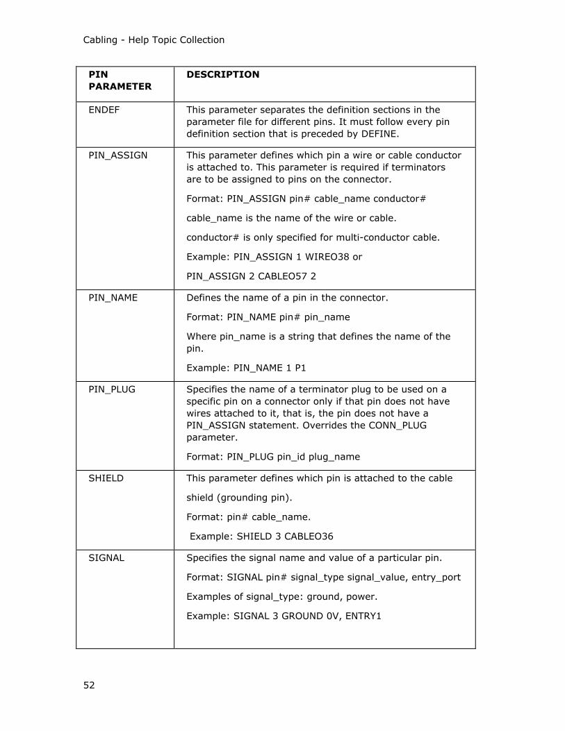
Cabling - Help Topic Collection
52
PIN
PARAMETER
DESCRIPTION
ENDEF This parameter separates the definition sections in the
parameter file for different pins. It must follow every pin
definition section that is preceded by DEFINE.
PIN_ASSIGN This parameter defines which pin a wire or cable conductor
is attached to. This parameter is required if terminators
are to be assigned to pins on the connector.
Format: PIN_ASSIGN pin# cable_name conductor#
cable_name is the name of the wire or cable.
conductor# is only specified for multi-conductor cable.
Example: PIN_ASSIGN 1 WIREO38 or
PIN_ASSIGN 2 CABLEO57 2
PIN_NAME Defines the name of a pin in the connector.
Format: PIN_NAME pin# pin_name
Where pin_name is a string that defines the name of the
pin.
Example: PIN_NAME 1 P1
PIN_PLUG Specifies the name of a terminator plug to be used on a
specific pin on a connector only if that pin does not have
wires attached to it, that is, the pin does not have a
PIN_ASSIGN statement. Overrides the CONN_PLUG
parameter.
Format: PIN_PLUG pin_id plug_name
SHIELD This parameter defines which pin is attached to the cable
shield (grounding pin).
Format: pin# cable_name.
Example: SHIELD 3 CABLEO36
SIGNAL Specifies the signal name and value of a particular pin.
Format: SIGNAL pin# signal_type signal_value, entry_port
Examples of signal_type: ground, power.
Example: SIGNAL 3 GROUND 0V, ENTRY1

Cabling
53
PIN
PARAMETER
DESCRIPTION
TERMINATOR Specifies the terminator name of a particular pin.
Format:
TERMINATOR pin# term_model_name auto_assign
Where "term_model_name" is a text string that defines
the Terminator name and "auto_assign" determines if the
terminator information is to be derived from a terminator
table.
Example: TERMINATOR 6 TERM6327Y TRUE
USER_DEFINED Any user defined parameter can be added with this format.
Format: Parameter_name value
Example: PIN_MATERIAL COPPER
To Edit Parameters for Components, Pin, or Entry Port Data
1. Click CABLING > Components > Modify Parameters. The SELECT dialog box
opens.
2. Select one or more connectors to modify and click OK. The Electrical
Parameters dialog box opens. The selected connectors appear in the left panel
in a tree navigation format.
3. Click the plus sign for a component to expand the component you want to edit.
The parameters of the pins and entry ports are displayed in the right panel.
4. Under Display For, click Components, Pins or Entry Ports to show the
parameters associated with them.
5. Modify the required parameters.
6. Click Apply and then OK.
To Redefine Splice Placement
1. Open the assembly in Standard mode to change the orientation of the splice.
2. Click CABLING > Components > Modify Components.
3. Select the splice that you want to redefine. The MOD CONN menu appears.
4. Click Placement. The COMPONENT WINDOW and Place Component dialog
box open.

Cabling - Help Topic Collection
54
5. Change the constraint type to one of the following:
o Tangent to Cable—The attachment coordinate system attaches to the
location that you selected earlier with its z-axis tangent to the cable
segment at the location.
o Perpendicular to Plane—select a Plane, Crv/Edg/Axis, or Csys from
the GEN SEL DIR menu as a constraint to assemble the splice or custom
component. The z-axis of the coordinate system is normal to the selected
plane or aligned to the selected curve, edge, axis, or coordinate system.
You can modify the direction of the attachment location to be parallel to the
z-axis of the attachment entry port.
6. Click OK in the Place Component dialog box. The splice is repositioned to the
new location.
About Replacing Connectors
Use the functional interchange group members (INTRCH GROUP) to replace the
assembly components that represent a connector with wires routed to it. In a
functional interchange assembly, each coordinate system that has a wire routed to it
on the connector being replaced must have a corresponding coordinate system on
the replacement connector with an assigned tag.
Note:
• The harness part must be regenerated to show the wires being routed to the new
entry ports on the new connector.
• If the connector is a subassembly, any entry port of any connector must be
represented by a coordinate system that resides on the top level of that
connector.
To Replace a Connector
1. Select the connector you want to replace.
2. Click Edit > Replace. The Replace Comp dialog box opens. You are prompted
to select the components to replace.
3. Click the By Model tab and select one of the following:
o Reference Model—Replaces a component model with a model containing
an external reference of the model.
o Layout—Replaces a component model with a model associated through a
layout.
o Manually—Replaces a component model by specifying placement of a new
model.
4. In the Selected Model box, select a model to replace.
5. Click OK. The Component Placement dialog box opens.

Cabling
55
6. Select the constraints and references.
7. Click OK.
Using Subconnectors
About Subconnectors
When you attach a subconnector to a connector, the entry port information on the
subconnector is associated with the parent connector.
A 3D assembly may have components designated as connectors, but no entry ports.
The entry ports for these connectors may be on separate parts or subassemblies on
the assembly, for example, a PC case and its serial and parallel connectors.
Subconnectors are necessary when a Diagramming file represents the PC case as
one reference designator, and the connectors as pins. In the 3D assembly, if each
serial or parallel connector part is assigned as a subconnector of the case part, the
logical reference searches the subconnectors for entry port names listed in the
diagram connector's pin information.
A represents a Diagramming connector C1, for example a computer case, showing
the case's ports as pins 1, 2, and 3. Each pin has the entry_port parameter with a
value matching the entry_port pin parameter on the subconnector part.
B represents the 3D assembly with parts D1, D2, and D3 as subconnectors of C1. C1
has no entry ports of its own, but each subconnector has one. Each subconnector
entry port is available to be assigned to the entry_port parameter for pins on C1.
Use Modify Parameters to assign the parameters to the subconnectors.
To Assign a Connector as a Subconnector
1. Click Cabling > Components > Modify Component.
2. Select the component that will receive the subconnector. The MOD CONN menu
appears.
3. Click Add SubConn. Select the connector to be added as a subconnector. A
message appears that the subconnector has been added successfully.
Note:
• To remove the subconnector, click Remove SubConn.
• To highlight a connectors assigned subconnectors, click Show Subconns.

Cabling - Help Topic Collection
56
• To list all connector with subconnectors, click List Subconns.
To Assign Subconnector Entry Ports
1. Click CABLING > Components > Modify Parameters. The SELECT dialog box
opens.
2. Select the parent component and click OK. The Electrical Parameters dialog
box opens.
3. Under Display For, select Pins.
4. Expand Pins to display the pins used in the assembly.
5. In the right panel, select an ENTRY_PORT parameter.
6. In the Value box, type a new value or select the entry port name from the list.
7. Repeat this procedure for each pin. Subconnector entry ports are assigned to pin
numbers on the parent connector:
Note: Entry ports must first be defined on each subconnector.
Using Entry Ports
About Entry Ports
An entry port is a coordinate system of a connector that you designate as accessible
to route a wire, cable, or bundle. Entry ports represent the pins in pin-to-pin cabling
connections. A conductor always leaves an entry port tangent to the positive z-axis
at the origin of the entry port coordinate system. You can define any coordinate
system on a part as an entry port. Typically, you do this when you designate the part
as a connector.
Note: To be an entry port, the coordinate system must be at the top level of the
model representing the component, that is, at the part level for a part or at the top
level of a subassembly.
After a coordinate system is designated as an entry port, you can assign this
coordinate system to a specific pin on the connector. You do not have to do this to
route a cable to an entry port manually, but the coordinate system is required for
autorouting individual conductors within a cable.
To Designate a Coordinate System as an Entry Port
1. Click CABLING > Components > Designate to designate a component as a
connector.
2. Select the component. The MOD CONN menu appears.
3. Click MOD CONN > Entry Ports. The ENTRY PORT menu appears.
4. Click Add/Modify and select a coordinate system.

Cabling
57
5. You are prompted to enter the internal length of the cable.
6. Type the length and press ENTER. The PORT TYPE menu appears.
7. Select WIRE, ROUND or FLAT as the port type. Wire denotes a single wire
whereas, round or flat refer to the packing for cables. You cannot route a cable to
a wire entry port.
You can also use the Autodesignate dialog box to designate the entry ports.
8. Continue to define all the entry ports. When finished, exit the command
sequence.
The internal length is not actually routed, but is specified in a numerical
parameter for each entry port. These lengths are automatically added to the
routed length of a wire when Cabling provides length information.
When you have designated one or more coordinate systems as entry ports on a
connector, the parameters EP_TYPE (round, flat, wire) and INT_LENGTH (integer)
are added for each at the entry port level of the connector in the Electrical
Parameters dialog box.
To Assign an Entry Port to a Pin Number
1. Click Cabling > Components > Modify Parameters.
2. Select one or more connectors with the pins you want to associate. The
Electrical Parameters dialog box opens.
Ensure that the NUM_OF_PINS parameter has an appropriate value to be assigned
to the entry ports.
3. Under Display For, click Pins.
4. If no column are displayed, click View > Columns to add the required
parameters.
5. In the Value box, for each pin, type the name of the coordinate system you want
to associate with the pin as a value for the ENTRY_PORT parameter or select the
entry port name from the list.
To Redefine an Entry Port
1. Click CABLING > Components > Modify Component.
2. Select the target component from the assembly.
3. Click MOD CONN > Entry Ports > Add/Modify. The SELECT dialog box opens.
4. Select an entry port or ports to modify.
5. Click OK. You are prompted to assign new values for the internal length and the
wire, flat, and round designation for all selected entry ports.

Cabling - Help Topic Collection
58
Using Terminators and Terminator Tables
About Terminators and Terminator Tables
A terminator is a cabling object with a set of parameters. Terminators are attached
to the pins of a connector to represent contact, crimp, or other terminator style
information. The term_name parameter is used to assign a terminator to a pin.
Use CABLING > Terminators > Create to create a terminator. For a given
terminator, you can create any number of user-defined parameters using the
Electrical Parameters dialog box.
You must first create a terminator and then attach its name to a pin either manually
or through a terminator table. In a large design, instead of manually attaching
terminators to each pin, you can create a terminator table to automatically assign
specific terminators to a specific group of pins.
A terminator table defines the criteria for a terminator to be matched to a particular
pin. Specify such criteria in the Terminator Table dialog box and run the table. You
can add or modify the default criteria to include any connector, connector pin, spool,
or spool conductor parameter. By specifying combinations of parameters in a
terminator table, any connector pin that meets the required criteria is automatically
assigned the specified terminator.
The terminator table columns define the connector and spool parameters. The first
column contains the term_name value. This value is the terminator name that is to be
associated with connections that match the criteria in the remaining columns.
Use the terminator table to assign terminators based on the diameter of the wire and
the connector model name. When you regenerate the cabling assembly, the
connector terminator statement is updated according to the latest terminator table
that you have run. Settings in a terminator table do not override terminators that
you have manually assigned, unless you specify otherwise.
Note:
• Before you assign a terminator to a connector manually or through a table,
ensure that the NUM_OF_PINS parameter is defined in the connector parameter
file.
• You can use only those terminators that were created before you start
assembling the components.
• Terminators are created as features in Cabling and displayed on the Model Tree.
To Use a Terminator Table
1. Click CABLING > Set Up > Term Table. The Terminator Table dialog box
opens.
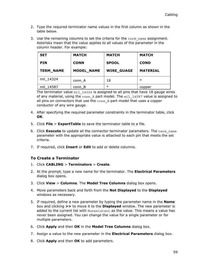
Cabling
59
2. Type the required terminator name values in the first column as shown in the
table below.
3. Use the remaining columns to set the criteria for the term_name assignment.
Asterisks mean that the value applies to all values of the parameter in the
column header. For example:
SET
PIN
TERM_NAME
MATCH
CONN
MODEL_NAME
MATCH
SPOOL
WIRE_GUAGE
MATCH
COND
MATERIAL
mil_14324 conn_A 18 *
mil_14587 conn_B * copper
The terminator value mil_14324 is assigned to all pins that have 18 gauge wires
of any material, using the conn_A part model. The mil_14587 value is assigned to
all pins on connectors that use the conn_B part model that uses a copper
conductor of any wire gauge.
4. After specifying the required parameter constraints in the terminator table, click
OK.
5. Click File > ExportTable to save the terminator table to a file.
6. Click Execute to update all the connector terminator parameters. The term_name
parameter with the appropriate value is attached to each pin that meets the set
criteria.
7. If required, click Insert or Edit to add or delete columns.
To Create a Terminator
1. Click CABLING > Terminators > Create.
2. At the prompt, type a new name for the terminator. The Electrical Parameters
dialog box opens.
3. Click View > Columns. The Model Tree Columns dialog box opens.
4. Move parameters back and forth from the Not Displayed to the Displayed
windows as necessary.
5. If required, define a new parameter by typing the parameter name in the Name
box and clicking >> to move it to the Displayed window. The new parameter is
added to the current list with Nonexistent as the value. This means a value has
never been assigned. You can change the value for a single parameter or for
multiple parameters.
6. Click Apply and then OK in the Model Tree Columns dialog box.
7. Assign a value to the new parameter in the Electrical Parameters dialog box.
8. Click Apply and then OK to add parameters.

Cabling - Help Topic Collection
60
To Read a Terminator
1. Click CABLING > Terminators > Read. The Open dialog box opens.
2. Select the terminator that you want to read from the disk.
3. At the prompt, type Yes if you want to overwrite the existing terminator.
To Modify Terminators
1. Click CABLING > Terminators > Edit to modify the terminator parameters. The
Select Terminators dialog box opens.
2. Select the required terminator or all the terminators from the list and click OK.
The Electrical Parameters dialog box opens.
3. Modify the value of the required parameter in the Electrical Parameters dialog
box and click OK to apply the changes.
Note:
• Use CABLING > Terminators > Read to read in terminator parameter data
from a previously created terminator that was saved to disk. This file must have
a .trm extension.
• Use CABLING > Terminators > Write to write the selected terminator
parameter data to your current directory. These files have a .trm extension.
To Write a Terminator
1. Use CABLING > Terminators > Write to write the terminator parameters to
the disk. The Select Terminators dialog box opens.
2. Select the required terminator or all the terminators from the listed that you want
to save to the disk and click OK.
3. Modify the value of the required parameter in the Electrical Parameters dialog
box and click OK to apply the changes.
Note:
• Use CABLING > Terminators > Read to read in terminator parameter data
from a previously created terminator that was saved to the disk. The file must
have a .trm extension.
• Use CABLING > Terminators > Write to write the selected terminator
parameter data to your current directory. These files are given a .trm extension.
To Rename a Terminator
1. Use CABLING > Terminators > Rename to rename the terminator. The Select
Terminators dialog box opens.
2. Select the required terminator from the list and click OK.

Cabling
61
3. At the prompt, type a new terminator name and press ENTER. The terminator is
renamed.
To Remove a Terminator
1. Click CABLING > Terminators > Remove. The Select Terminators dialog box
opens.
2. Select the required terminator from the list and click OK. The selected
terminators are removed from the diagram or cabling assembly.
To Get Information on Terminators
1. Click Info > Bill of Materials. The BOM dialog box opens.
2. Select the required options and click OK.
A list of all the terminators used and the quantity of these terminators is
displayed in the embedded browser.
3. To retrieve terminator information for a given harness or for the cabling
assembly, ensure that you have set the required harness part or the cabling
assembly as the active model.
The report symbols available to retrieve complete terminator information for a
given harness are:
o &harn.term.name
o &harn.term.qty
o &harn.term.<User Defined>
The report symbols available to retrieve complete terminator information for the
cabling assembly are:
o &asm.mbr.connprm.name
o &asm.mbr.connprm.pin.name
o &asm.mbr.connprm.pin.term.name
o &asm.mbr.connprm.pin.term.<User Defined>
Where <User Defined> is the parameter defined by you as per your requirement.
Note: Use CABLING > Terminators > List to view the list of terminators in the
diagram or cabling assembly.
Assigning a Terminator Based on the Sum of Multiple Wire Widths
Use the MIN_SUM and MAX_SUM parameters to choose terminators based on the total
summed area of potentially multiple wires routed to a pin.

Cabling - Help Topic Collection
62
SET
PIN
TERM_NAME
MATCH
CONN
NAME
MATCH
CONN
VENDOR
MIN_SUM
SPOOL
AREA
MAX_SUM
SPOOL
AREA
term1 conn1 amp .1 .25
term2 conn1 amp .25 .5
term3 conn1 amp * *
Note: The term_auto_assign pin parameter determines whether the pin's
term_name value can be automatically changed. Before you run a terminator table,
ensure that all the terminators you want to edit are eligible for modification, or
whether all or some terminators are protected when this parameter is set to False.
If the term_auto_assign parameter has never been set for a terminator, its value
does not exist in the Electrical Parameters dialog box. You can update such a
terminator.
Using Nets
About Nets
A net is a netlist file or a wirelist that contains information about the network of
wires in a diagram and is used as a logical reference to communicate between
Diagram and Harness layout. Cabling can read two types of wirelists:
• Wiring diagram wirelists—Every wire in a wiring diagram wirelist is defined by two
pins.
• Schematic diagram wirelists—Multi-pin nets can be included in a schematic
diagram wirelist. A multi-pin net is a set of wires connecting various devices,
without specific pin to pin connection list.

Cabling
63
For example, consider a connection as shown:
This connection generates the following possible configurations:

Cabling - Help Topic Collection
64
The input from the schematic diagram is a multi-pin netlist that lets you know that A
is connected with B and C, without specifying the wiring between them.
The neutral wirelist format (.nwf) imports both the wiring diagram wirelist as well as
the schematic diagram wirelist. Cabling reads the information regarding the multi-pin
network from the NWF file and uses it to create and route wires. Cabling requires the
existence of a network to route the wires that have not been defined by two pins,
using the shortest distance criterion.

Cabling
65
To Create a Net
1. Ensure that you have imported an NWF file.
2. Click CABLING > Feature > Create. The CABLE FEAT menu appears.
3. Click Net. The REF NET menu appears.
Note: The Net command on the CABLE FEAT menu is available only when nets
are present in the NWF file that you have imported.
4. Select one or more nets.
5. Click OK.
Note: You can use CABLING > Route > Net to route the wires using the
shortest distance criterion.
Using Parameters in Cabling
About Modifying Cable and Wire Parameters
You can modify cable, wire, or bundle parameters by
• Editing the current values
• Retrieving a file containing new parameter data
• Updating the parameters from logical reference data for any matched spool,
cable, or wire
When modifying the THICKNESS value, remember the following:
• If you modify surface offsets for locations individually, then when you modify the
dimension, the offset values are considered fixed and are no longer automatically
updated.
You must change the offset dimension manually to ensure that the cable does not
interfere with the surface as the diameter at the location increases. Either make
the surface offset larger to raise the cable above the surface, or change the
location offset back to Free Height, and let Cabling do so.
• If the bundle parameter, THICKNESS, is less than the sum of the thickness of all
its packed components, Cabling issues a warning.
• Changing the thickness of a spool does not automatically update the THICKNESS
parameter of a bundle created from the cables referencing the spool. To update
the bundle thickness, you must regenerate the harness part from the CABLING
menu. This is valid for regular cables as well.
You can add columns to the Model Tree that display the status of a particular
feature, the type of feature, or information about a feature (such as parameters).
Feature parameters can apply to any feature in an object, while model parameters
apply only to an entire model.

Cabling - Help Topic Collection
66
Note: You can use the Wire, Cable, or Sheath spool parameters to define the shape
of the cabling objects, such as wires and cables. For example, THICKNESS,
MIN_BEND_RADIUS, and so on.
To Add or Delete Parameters of the Cabling Objects
1. Click CABLING > Modify. The MOD CABLE and MODIFY menus appear.
2. Click Parameters from the MOD CABLE menu. The SELECT dialog box opens.
3. Select the wires, cables, components, or connectors to modify.
4. Click OK. The Electrical Parameters dialog box opens.
5. Under Display For, select appropriately to show or hide the display of
parameters for different levels of the tree in the left panel. For example, for a
component, pin, conductor, entry port, and so on.
6. Click View > Columns. The Model Tree Columns dialog box opens.
7. Move parameters back and forth from Not Displayed to Displayed windows as
necessary.
8. If required, define a new parameter by typing the parameter name in the Name
box and clicking >> to move it to the Displayed window. The new parameter is
added to the current list with Nonexistent as the value. This means a value has
never been assigned. You can change the value for a single parameter or for
multiple parameters. If you click <<, the parameter name in the Displayed
window is moved to the Not Displayed window and removed from the current
list of parameters.
9. Click Apply and then OK in the Model Tree Columns dialog box.
10. Assign a value to the new parameter of any object in the Electrical Parameters
dialog box.
11. To delete a parameter, select the parameter that you want to delete in the right
panel of the dialog box and click Delete Parameter.
12. Click Apply and then OK.
To Specify Parameter Values Individually
1. Click CABLING > Modify. The MOD CABLE and MODIFY menus appear.
2. Click Parameters from the MOD CABLE menu. The SELECT dialog box opens.
3. To ensure that you select a correct cabling object, click or Edit > Find, and
select the required object.
or
Select the wires, cables, components, or connectors that you want to modify.

Cabling
67
4. Click OK in the SELECT dialog box. The Electrical Parameters dialog box
opens.
5. Under Display For, select appropriately to show or hide the parameters display
for different levels of the tree in the left panel. For example, for a component,
pin, conductor, entry port, and so on.
6. Select the parameter you want to edit in the right panel of the dialog box.
7. Type a new value for the parameter in the Value box and press ENTER. The new
value for the selected parameter appears in the right panel of the Electrical
Parameters dialog box.
8. Click Apply and then OK.
Note: Both the cable or wires and bundles cannot be displayed together in the
Electrical Parameters dialog box.
To Specify Parameter Values for Multiple Objects
1. Click CABLING > Modify. The MOD CABLE and MODIFY menus appear.
2. Click Parameters from the MOD CABLE menu. The SELECT dialog box opens.
3. To ensure that you select a correct cabling object, click or Edit > Find, and
select the required object.
or
Select the wires, cables, components, or connectors that you want to modify.
4. Click OK in the SELECT dialog box. The Electrical Parameters dialog box
opens.
5. Under Display For, select appropriately to show or hide the parameters for
different levels of the tree in the left panel. For example, for a component, pin,
conductor, entry port, and so on.
6. In the right panel of the dialog box, click multi-select for the object type that
you have selected. If a parameter for the object has any nonexistent values, you
can change all values, including nonexistent values, to the new value or ignore
the Nonexistent values.
If the column has any nonexistent values, you can choose between:
o Create and Set—Changes all values, including nonexistent values, to the
new value.
o Set Existing Only—Ignores nonexistent fields.
7. Type a new value for the parameter in the Value box and press ENTER. The new
value for the selected parameter appears in the right panel of the Electrical
Parameters dialog box.

Cabling - Help Topic Collection
68
8. Click Apply and then OK. All values in a column for a selected object are
changed to the new value.
Note: Both the cable or wires and bundles cannot be displayed together in the
Electrical Parameters dialog box.
To Specify a Value for Pin Names Across Multiple Connectors
1. Click CABLING > Modify. The MOD CABLE and MODIFY menus appear.
2. Click Parameters from the MOD CABLE menu. The SELECT dialog box opens.
3. Select the connectors that you want to modify.
4. Click OK in the SELECT dialog box. The Electrical Parameters dialog box
opens.
5. Under Display For, click Pins.
6. Expand Common Pins.
7. In the right panel of the Electrical Parameters dialog box, select the specific
pin name and the parameter value that you want to edit. Values for most
columns are As Is. This means that values differ for the same pin name across
connectors.
8. Type a new value for the parameter in the Value box and press ENTER. The
values for the selected parameter are updated across all listed connectors for the
specified pin.
9. Click Apply and then OK.
To Specify a Single Value for Parameters Across Multiple Connectors
1. Click CABLING > Modify. The MOD CABLE and MODIFY menus appear.
2. Click Parameters from the MOD CABLE menu. The SELECT dialog box opens.
3. Select the connectors that you want to modify.
4. Click OK in the SELECT dialog box. The Electrical Parameters dialog box
opens.
5. Under Display For, click Pins.
6. Expand Common Pins.
7. In the right panel of the dialog box, click multi select to the right of Common
Pins and above the parameter you want to edit. A prompt appears above the
tree headings. Values for most columns are As Is. This means that values differ
for the same pin name across connectors.
8. Type a new value for the parameter in the Value box and press ENTER. The
values for the selected parameter are updated across all listed connectors for the
specified pin.

Cabling
69
9. Click Apply and then OK.
To Flip Cable Ends
1. Click CABLING > Modify. The MOD CABLE and MODIFY menus appear.
2. Click Parameters from the MOD CABLE menu. The SELECT dialog box opens.
3. Select a cable or wire that you want to modify. The cable or wire must have both
from and to connectors.
4. Click OK in the SELECT dialog box. The Electrical Parameters dialog box
opens.
5. Click Flip Cable Ends to flip the from/to connectors of the selected cable.
To Display Cable or Wire Parameters in the Model Tree
1. In the left pane of the Cabling window, click Settings > Tree Filters. The Model
Tree Items dialog box opens.
2. Select the features of the Cabling assembly that you want to view in the left pane
of the Cabling window.
3. Click OK to apply the changes and close the Model Tree Items dialog box.
4. Click Settings > Tree Columns. The Model Tree Columns dialog box opens.
5. In the Type list, select Cabling Params.
6. Type a parameter name in the Name box at the bottom left of the dialog box or
select a parameter name from the list of available parameters and press ENTER.
The new parameter is added to the Displayed list.
7. Click Apply and then OK. The dialog box closes and the new parameter column
is added to the model tree.
8. If required, add more columns to the model tree to display the status of a
particular feature.
Adding a Parameter to a Note
The value of a parameter evaluated in your cabling assembly can be placed as a note
in drawings of 3D or flat harnesses. You can attach the note to a connector, bundle,
cable, or wire with or without a leader.
A parameter can be included in the note by adding ¶m_name:att to the note
where param_name is the name of the parameter whose value you want to use in the
note. The parameter value must exist before the note is created. By default, the
value of the parameter that is extracted is based on the item to which the note is
connected.
If you attach &name:att as a note to a cable, the name of the cable appears in the
note. However, if you want a specific type of parameter to be used, add

Cabling - Help Topic Collection
70
_param_type to the note, where param_type is the type of parameter you want to
use. For example, you can use the name of a spool used for a wire in a note by using
the note, &name:att_spool. Attaching this note to a wire shows the name of the
spool that was used to create the wire instead of the name of the wire itself.
Cabling Parameters
The following is a list of cabling parameters arranged by object.
Component Parameters
REF_DES (Text String)
MODEL_NAME (Text String)
NUM_OF_PINS (Integer)
TYPE (Text String)
CONN_PLUG (Text String)
USER_DEFINED (Text String)
OBJ_TYPE (Text String)
DEF_INTERNAL_LENGTH (Integer)
DEF_GROUPING
TABLE_AUTO_ASSIGN (True/False)
Connection Parameters
NAME (Text String)
SPOOL (Text String)
REF_DES_FROM (Text String)
ENTRY_PORT_FR (Text String)
REF_DES_TO (Text String)
ENTRY_PORT_TO (Text String)
MAX_ALLOWED_LENGTH (Integer)
MAX_ALLOWED_DST (Integer)
TARGET_LENGTH (Integer)
FROM_TO_CABLE_REPORT_NAME (Text String)
TO_CABLE_REPORT_NAME (Text String)
FROM_CABLE_REPORT_NAME (Text String)
USE_PATH (Text String)
NETWIRE (Integer)
MIN_ALLOWED_DIST (Integer)

Cabling
71
TYPE (Text String)
Pin Parameters
SIGNAL_NAME (Text String)
SIGNAL_VALUE (Text String)
ENTRY_PORT (Text String)
TERM_NAME (Text String)
TERM_AUTO_ASSIGN (True/False)
CABLE_NAME_SHIELD (Text String)
PLUG_MODEL_NAME (Text String)
PIN_NAME (Text String)
CABLE_NAME_# (Text String)
COND_ID_# (Integer)
TABLE_AUTO_ASSIGN (True/False)
TERM_PIN_ID (Integer)
Entry Port Parameters
TYPE_EP (ROUND, FLAT, WIRE)
INT_LENGTH (Integer)
LINK (Text String, another entry port's name)
Bundle Parameters
NAME (Text String)
BUNDLE_TYPE (ROUND, FLAT)
MIN_BEND_RADIUS (Integer)
THICKNESS (Integer)
SPOOL(Text String)
SHEATH SPOOL(Text String)
ADDITIONAL NAMES (Text String)
ASSIGNED_MIN_BEND_RADIUS
ASSIGNED_THICKNESS(Integer)
LINESTYLE
MATERIAL DENSITY (Integer)
MIN_ALLOWED_LENGTH (Integer)
MAX_THICKNESS (Integer)

Cabling - Help Topic Collection
72
MIN_ALLOWED_DIST (Integer)
OVERLAP_FACTOR
Conductor Parameters
WIRE_NAME (Text String)
STRIP_LENGTH_FROM (Text String)
AUTO_ASSIGN_FROM (Text String)
STRIP_LENGTH_TO (Text String)
AUTO_ASSIGN_TO (Text String)
COLOR (Text String) (If a string matches the string present in View > Colors and
Appearance, cables are displayed in that color.)
LINESTYLE (Text String) (solidfont, dotfont, and so on)
Routing Cables
About Routing Cables
When you have defined spools in the database and created wires or cables from the
spools, you are ready to add actual cables to the design. You can do this manually or
automatically.
Routing manually, you first add a cable or cables to a routing set, then install
dimensionally constrained points called locations to identify the path of the set. The
first location can reference a point on an assembly surface or can be attached to an
entry port on a connector. To capture the design intent, the locations may be fixed
on surfaces, offset, or dependent on other locations. Therefore, if the assembly
surfaces are moved, the cable moves with them.
As you are routing, you can click Switch End to activate the opposite end of the
cable or Reset Loc to reset the start location. Use Del Portion to remove a
segment between two selected locations.
Autorouting
Using autorouting, you first lay out a default backbone or network of locations where
you want the main trunk of the harness. Like cables, the network is associated with
the current working harness. The network location points have the same properties
as location points used in interactive routing. Additionally they can be assigned
priorities by connection to better define the paths for the autorouter.
Networks are by default harness-specific, but you can elect to share a network
across harnesses, if one network will define a suitable path for two harnesses.
When you have added the network, use the Cabling > Route menu to select cables
to route, then use the Autoroute subcommand to complete the routing.

Cabling
73
Manual Routing
To add cables interactively, you first select the cable or cables you want to route,
then you use the cursor to add locations along the path of the cable. The first and
last locations are usually entry ports on connector components.
Locations along the path of the cable can be free or dependent. Free locations move
when you move the cable. Dependent locations associate the cable with an offset
from a component, so if the component dimensions are edited, the cable length or
position is edited accordingly. Cables that you route are added to the current
working harness. Use the commands on the Cabling > Route menu to start the
interactive routing process.
In the following figure, the individual conductors of a cable routed to entry ports
represent pins.
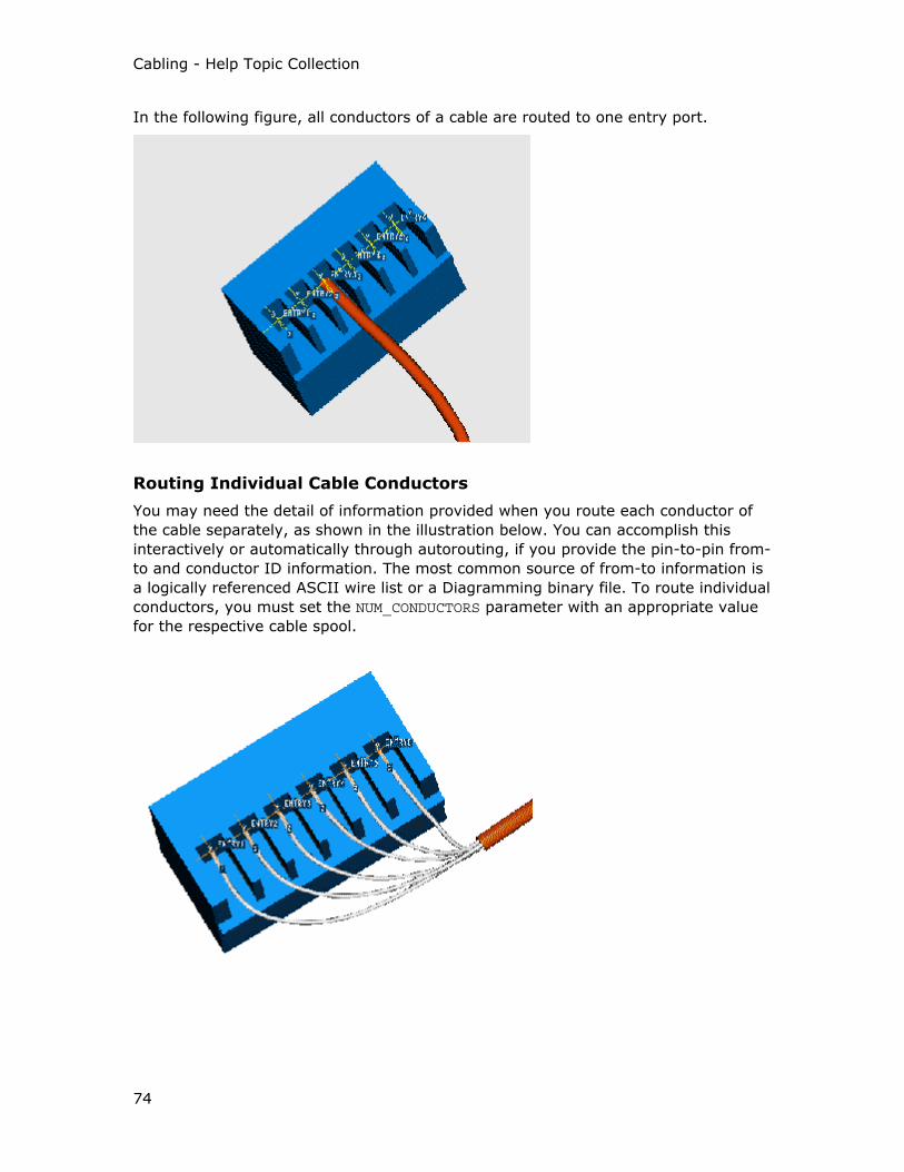
Cabling - Help Topic Collection
74
In the following figure, all conductors of a cable are routed to one entry port.
Routing Individual Cable Conductors
You may need the detail of information provided when you route each conductor of
the cable separately, as shown in the illustration below. You can accomplish this
interactively or automatically through autorouting, if you provide the pin-to-pin from-
to and conductor ID information. The most common source of from-to information is
a logically referenced ASCII wire list or a Diagramming binary file. To route individual
conductors, you must set the NUM_CONDUCTORS parameter with an appropriate value
for the respective cable spool.

Cabling
75
To Control Cable Shape
1. Click CABLING > Route.
2. Select the items to route. The CABLE SEL, ADD CABLES, and ADD CBL SEL
menus appear.
3. Use the ADD CBL SEL menu to select or create a cable.
4. Click Done Sel. The CBL ROUTE menu appears.
5. Click Cable Envr. The CABLE ENVR menu appears.
This command lets you control the shape of the routed cable. The settings are
stored with the assembly and are recalled from one routing operation to the next,
and for all harnesses, until you change the setting. The settings are applicable
only for the current Pro/ENGINEER session.
When you route the cable using straight conditions, the cable appears more as a
line/arc combination with straight line segments and connecting splines
alternating as close to arcs as possible. However, smooth routing is used by
default when straight conditions cannot be maintained.
The Round or Flat type of grouping does not control the grouping of individual
items within a bundle routed through a location; that is determined by the
bundle-type parameter value.
6. Select the appropriate shape of the routed cable and click Done/Return to
establish the shape of the cable's cross section.
To Select Cables to Route
1. Click CABLING > Route. The CABLE SEL menu appears. The SELECT dialog
box also opens.
2. Select a wire.
3. Click OK to complete your cable selection. The CABLE SEL, ADD CABLES, and
ADD CBL SEL menus appear.
Using the CABLE SEL menu, you can:
o Add selected cables to the routing set
o Remove selected or all cables currently being routed from the set. Use the
Add command to create a new set before routing.
o Create a bundle containing the selected cables.
You can select conductors from several cables before choosing and routing
wires. Use the multiple selection operations, for instance, you can select
conductors from several cables before choosing and routing wires.

Cabling - Help Topic Collection
76
To filter your selection for routing using the ADD CABLES menu, you can:
o Route a continuous segment between two connectors
o Route a network of wires using the shortest distance
o Limit your choice of cable selection to only those cables or wires not yet
completely routed (that is, attached to two connectors with a continuous
length of cable).
Note: If a component of a bundle is completely routed, it is considered
complete and does not show in the selection menu if you specify the
Incomplete command.
If any conductor in a cable is completely routed, that cable is considered
complete and does not show in the selection menu.
Any segment of a wire or cable that is already partially routed either
between an entry port and a location or between two locations using
manual routing is considered incomplete.
o You can select entire cable features for routing or select individual cable
conductors for routing if they have been defined individually in the cable
spool.
Using the ADD CBL SEL menu you can:
o Select existing wires, cables, bundles, or cable conductors to add to the set
and a location that will select all items routed through the location.
o Select wires routed to the connector if there is no logical reference; selects
those wires routed to the connector in the reference data if there is a logical
reference
o Create a cable or wire to be added to the set
If you select the Create command, you are prompted to create a new wire
or cable. After choosing either Wire or Cable, you can continue creating
the new feature as if you had chosen CABLE FEAT > Wire or CABLE FEAT
> Cable. Wires or cables created now are automatically added to the set of
cables you select to route.
The Create command allows you to remove all the cables in the set to
select a completely new set of cables to route without leaving the CBL
ROUTE menu or remove the selected cables.
If the current set contains more than one wire or cable, you can create a
bundle from any of the cables in the current set. The current set remains
active until you change it or end the routing process.
4. Click Done/ Return to end the routing process.
To Add or Remove Cables from the Routing Set
1. Click CABLING > Route.

Cabling
77
2. Select the items to route. The CABLE SEL, ADD CABLES, and ADD CBL SEL
menus appear.
3. Use the ADD CBL SEL menu to select or create a cable.
4. Click Done Sel. The CBL ROUTE menu appears.
5. Click the Change Cbls command from the CBL ROUTE menu.
6. Click the Add or Remove command from the CABLE SEL menu.
To Split Cables
1. Click CABLING > Modify. The MOD CABLE and MODIFY menus appear.
2. Click Split Cable from the MOD CABLE menu. The SELECT dialog box opens.
3. Select a cable that you want to split.
4. Select a location at which you want to split the cable and click OK. The harness is
regenerated.
5. At the prompt, type different names for the two separate cables. The cable is
successfully split into two separate cables at the selected location.
To Route Along an Existing Cable
1. Click CABLING > Route.
2. Select the items to route. The CABLE SEL, ADD CABLES, and ADD CBL SEL
menus appear.
3. Click Select from the ADD CBL SEL menu. The SELECT dialog box opens.
4. Select the cable and click OK.
5. Click Done Sel in the CABLE SEL menu. The CBL ROUTE menu appears.
6. Route to a network location that is used by the cable that you want to follow.
7. Click Follow Cable and select the cable to follow the same path as an existing
cable.
8. To ensure that you follow the correct cable, click or Edit > Find, and select
the required cable.
9. Select another location on the cable that you are following. The cable being
routed is now automatically routed upto this second location through all the
intermediate locations that the cable being followed goes through.
To Route Through a Hole
1. Click CABLING > Route.

Cabling - Help Topic Collection
78
2. Select the items to route. The CABLE SEL, ADD CABLES, and ADD CBL SEL
menus appear.
3. Click Select from the ADD CBL SEL menu. The SELECT dialog box opens.
4. Select the cable and click OK.
5. Click Done Sel in the CABLE SEL menu. The CBL ROUTE menu appears.
6. Click Along Axis and select an axis to route the cable along an existing axis.
When you select the Along Axis command as the first routing command for a
segment, you are prompted to select the direction in which the cable is to be
routed.
7. To ensure that you select the correct axis, click or Edit > Find, and select
the required axis. The Along Axis command creates two locations at the
endpoints of an axis in one step. The cable is tangent to the axis at the locations.
This guarantees that the cable entity passes through the hole normal to the
surfaces. (The assumption is that the axis is in a hole.)
If a cable must pass through a hole but does not have to be tangent to the axis,
you can create a Free location and select the axis. Only a single location on the
axis is created.
Note: If you want to route through clamp-down clips, these parts should be
created with an axis and assembled first. Then, route from axis to axis. This
method guarantees a smooth trajectory through the parts.
To Route Through an Axis Offset From Surfaces
1. Click CABLING > Route.
2. Select the items to route. The CABLE SEL, ADD CABLES, and ADD CBL SEL
menus appear.
3. Click Select from the ADD CBL SEL menu. The SELECT dialog box opens.
4. Select the cable and click OK.
5. Click Done Sel in the CABLE SEL menu. The CBL ROUTE menu appears.
6. Click Offset Axis. You are prompted to select an axis and wire/cable direction.
7. To ensure that you select the correct axis, click or Edit > Find, and select
the required axis. The wire/cable is created along this axis and keeps the offset
from the surfaces that define the axis placement.
Single flat surface
When creating an axis using a surface and a datum plane, the selected surface will
be considered as a boundary for the cable. The cable moves perpendicular to this
surface and keeps no interference and no clearance.

Cabling
79
"V" shape
When creating an axis using two surfaces, the selected surfaces are considered a
boundary for the cable. The cable moves perpendicular to those surfaces and keeps
no interference and no clearance.
To Copy a Cable Path
1. Click CABLING > Route.
2. Select the items to route. The CABLE SEL, ADD CABLES, and ADD CBL SEL
menus appear.
3. Click Select from the ADD CBL SEL menu. The SELECT dialog box opens.
4. Select the cable and click OK.
5. Click Done Sel in the CABLE SEL menu. The CBL ROUTE menu appears.
6. With a routing set selected, click Copy Routing.
7. Select the cable whose path you want to copy.
The path and the sources of the new cable follow the selected cable.
Each cable selected for routing is routed along a path of the same shape as the
source cable. If the source cable has a fixed length, the newly-routed cables have
the same fixed length. If a portion of the source cable has a fixed length, the
corresponding portion of the newly-routed cables have the same fixed length.
The copied cable starts at one of its designated entry ports. It goes through
locations offset from the entry port's coordinate system; these locations are
offset from each other by the same amount as the source cable's locations are.
If any cables cannot be completed you are prompted about the problem.
Tip: Updating Locations During Routing
When a cable is routed, Cabling creates new features to represent both the cable and
the locations that the cable passes through.
A cable retains information about where it passes through a location, but the location
is responsible for packing all entities that pass through it. Subsequent cables routed
to the same location are arranged by the location relative to their neighbors.
During routing, Cabling may display a message prompting you to regenerate the
cables, to see the correct packing on the screen.
In this case, Cabling is updating the location, but it is possible that some of the
earlier cable features are not aware of the location's changes. As a result, not all
cables are updated immediately on the screen.
When you regenerate the cables, Cabling goes back and updates not only each
location, but each cable entity as well, giving a completely updated model.

Cabling - Help Topic Collection
80
To Set a Cable to a Fixed Length
1. Click CABLING > Modify. The MOD CABLE and MODIFY menus appear.
2. Click Length from the MOD CABLE menu. The CABLE LENGTH menu appears.
3. Click Fix. You are prompted to select locations that are the endpoints of the
segment.
4. Select the two required locations on the cable to apply a fixed length to a
segment. The system displays the current length of the segment which you can
accept or modify. You can then use this dimension in a relation.
Note:
• Use CABLING > Modify > Length > Show to display the dimensions of a fixed
length cable.
• Use CABLING > Modify > Length > Change to modify the value of a fixed
length cable.
• Use CABLING > Modify > Length > Free to remove the fixed length constraint
of the cable so that the cable no longer has a fixed length.
To Calculate the Current Length of a Segment
1. Click CABLING > Relations. The Relations dialog box opens.
2. Click Utilities > Evaluate. The Evaluate Expression dialog box opens.
3. Specify Cabling mode function cable_len() in the Expression box to calculate
the length of a cable.
To calculate the current length of any segment of a cable or bundle, use the
following syntax:
cable_len ("cable_name",location_id1,location_id2)
To calculate the length for the complete cable from end to end, use the following
syntax:
cable_len ("cable_name",-1,-1)
where
• cable_name is the name of the cable being measured in the current
harness.
• location_id is the internal feature ID of the location through which the
cable_name is routed. Where 1 and 2 denote the two cable locations
between which the length is to be calculated.
4. Click Evaluate. The length of the cable or bundle is displayed in the Result box.
5. Click Close in the Evaluate Expression dialog box.

Cabling
81
6. Click OK in the Relations dialog box.
Using Bundles During Manual Routing
You can automatically place wires in a bundle during manual routing, thus reducing
the number of picks required to clean-up the routing, and simplify the display of the
harness.
When you select CBL ROUTE > Cable Env and check the Rt in Bndls checkbox,
manually routed wires behave the same way as autorouted wires. If wires are
manually routed using FOLLOW CABLE along a path occupied by a bundle, these
wires are automatically added to that bundle. If more than one bundle exists along
that path, you are prompted to select which you want to use.
To Delete All or Part of an Individual Cable Segment
1. Click CABLING > Feature > Delete. The DELETE CABLE menu appears.
2. Click Cable Portion and select the bounding locations of the portion to be
deleted.
3. If more than one cable is routed through the selected locations, a DEL CABLE
menu appears that contains a list of all the cables that are routed through the
selected locations.
4. Select the cables to be deleted from the menu, and a check mark appears next to
the selections.
Note: Deleting a location using Del Feature deletes all children (cables and
bundles that are routed through the location).
5. If you want to remove a location from the harness but not delete the cable, or to
remove a single wire or wires from a location, use CABLING > Location >
Remove.
6. When you select a cable to delete, the first entity that appears is the cable
segment. If you want to delete the entire cable, use Edit > Find and select the
cable you want to delete.
Note: If you delete all cable or bundle portions from the assembly, this still does
not remove it from the list of available cables that can be routed. The cable or
bundle feature still exists.
To Get Cable and Wire Info from the Display
1. Click Info > Cabling from the menu bar to get information about selected
harnesses, networks, and cables in the assembly. The Cabling Information
dialog box opens.
2. Use the Information Type options and the associated options to set up an
information readout. When you have set up the query, click Apply.

Cabling - Help Topic Collection
82
3. If you choose any one of the harness options say, Individual or Partial, the
HARNESSES menu appears with a list of existing harnesses in the part. Select
the harness whose information you want to display, the INFORMATION WINDOW
appears.
Using this procedure, you can get the name, conductor contents, and highlight the
path of any selected cable, network, or harness feature.
To Check Cable Clearance
1. Click Analysis > Model Analysis from the main menu line. The Model Analysis
dialog box opens.
2. Select Pairs Clearance in the Type box.
3. Select From/To items to measure the clearance.
4. Select whether you want to check the clearance along the whole cable feature by
Cable or only for a segment by choosing Single entity.
5. Select a cable from the assembly. If you chose the Cable command in the
previous step, the entire harness is used to measure clearance. If you chose the
Single entity command in the previous step, the segment you select is used to
measure clearance.
6. You can select the Whole subasm, Whole part, and Surface commands as
items to measure clearance From and/or To. You can select a harness part using
the Whole Part command.
7. When you select a harness part with the Whole part selection type, Cabling
calculates the clearance between the entire harness part and the other selection
(such as a second harness part) in the same way an individual cable is chosen
with the Cable command.
8. Select the second cable or assembly component.
9. Click Compute. The clearance between the selected items is displayed in the
Results box. If you click Info, an INFORMATION WINDOW opens with the
clearance results displayed in the window.
10. Click Close to exit the Model Analysis dialog box.
Note: You can determine the clearance between cables, and between cables and
assembly members.
To Check Global Clearance for Harnesses
1. Click Analysis > Model Analysis. The Model Analysis dialog box opens.
2. Select Global Clearance in the Type box.
3. Click the Include to include harness parts in the Harness box.
4. Click Compute. Cabling calculates the global clearance of each harness part and
the information appears in the Clearance window in the Setup box.

Cabling
83
5. Click Close to exit the Model Analysis dialog box.
Note: You can include harness parts in the global clearance checking process. The
checking of harness parts does not include the checking of interferences between
cables within a harness part. The check is between the entire harness part and other
parts, such as assemblies and harness parts.
To Route Individual Conductors
Use this procedure to route individual cable conductors to selected entry ports.
Cables must be in the Centerline mode. Ensure that you set the NUM_OF_CONDUCTORS
parameter for the respective cable spools before routing.
1. Click CABLING > Route.
2. Select the items to route. The CABLE SEL, ADD CABLES, and ADD CBL SEL
menus appear.
3. Select Conductors from the ADD CABLES menu.
4. Click Select from the ADD CBL SEL menu. The SELECT dialog box opens.
5. Select the wire or cable to route conductors from and click OK. The SEL
CONDUCTORS menu appears.
6. Check the boxes for the conductor or conductors you want to select an entry port
for. To route a wire to an entry port, check the wire before you proceed. If you
want to route more than one wire to an entry port, check the multiple boxes.
7. Click Done Sel, and CABLE SEL > Done Sel. The CBL ROUTE menu appears.
8. Click Entry Port and identify the connector and entry port you want to connect
to. A location is established on the entry port.
9. Click Location and click on the location at the end of the cable segment, where
you want the conductor to come from. The conductor is routed to the entry port.
Repeat from step 1 for each separate conductor you want to route.
In the following figure, individual conductors are routed to different entry ports.

Cabling - Help Topic Collection
84
Using Locations
About Locations
Locations are points, similar to datum points, that cables follow during routing. The
locations describe the offsets and fixed points of the cable's path through an
assembly. Use the locations to capture the design intent in case of changes to the
assembly's dimensions. You can assign dimensions and constraints to capture the
design intent of the cable and harness if changes are made to the assembly.
Locations are also required for autorouting. When you define a path, multiple wires
and cables can follow the path during autorouting. Two kinds of location points are:
• Free—You can place a free location as a point on any surface, curve, axis, or
network segment. It is automatically offset by 0.6 of the radius of the cable or
cables passing through the location. Free locations on curves, axes, or other
cable entities are always centered on the entity and tangency is not constrained.
• Dependent—A dependent location has the same default offset and directional
values as the free location, but you are prompted for a dimension from the
previously specified location, and an offset from a second selected surface. When
the reference entity is moved, the locations move with it.
Use the dependent location when you must route along a complex surface, when
the cable must follow a straight line as seen from the top or side view. If you
must move the cable, you can move only the reference location, and the
dependent locations move with it.
An offset location is similar to a dependent location, but lets you define the
location relative to three dimensions. Other location types place the path along a
selected axis or parallel to a channel. Use an Offset location to place cables in a
tight passage or cramped volume; the cables move relative to assembly
geometry. You can use the Offset command to create locations relative to a
global coordinate system, but you should avoid this exclusively because the
resulting trajectory has no reference to the assembly and does not capture your
design intent. As with Dependent type locations, Offset locations cannot be used
as a starting point for routing a cable set.
After specifying locations of any kind, you can optionally attach a width constraint
to them for the cable to be routed through the location.
To Create a Dependent Location
1. Click CABLING > Route > Select or CABLING > Network Ops > Route. For
the both routines, the CBL ROUTE menu appears.
2. Click Free. Use the pointer to make a new free location as a reference for the
Dependent location.
or
Select an existing free location.

Cabling
85
3. Click Dependent to route from or to a point and dimension to the previous
location.
4. Select a point on a curve or surface where you want to install a dependent
location. You are prompted to select the first direction.
5. Click or Edit > Find to select an edge, axis, or curve. You are prompted to
select a reference for the second direction.
6. Similarly, select an edge, axis, or curve for the second direction. The location is
installed where you clicked in step 3.
To Create a Use Dir Location
1. Click CABLING > Route > Select or CABLING > Network Ops > Route. For
the both routines, the CBL ROUTE menu appears.
2. Click Use Dir.
3. Select a straight curve or cable portion, axis, edge, or channel. The OFFSET
menu appears.
4. Select one of the following:
o Thru Point—Creates a parallel datum plane that intersects the point that
you specify on the part surface.
o Enter Value—Type an exact dimensional value for the datum to be offset
from the plane in the direction of the red arrow. If the arrow points in a
direction that is opposite the one where you want to send the location, type
a negative number.
Note: To modify the dimensional value of the offset, choose CABLING > Modify
and then select the location. Click Regenerate to view the results.
To Create an Offset Location
1. Click CABLING > Route or CABLING > Network Ops > Route routines. The
CBL ROUTE menu appears.
2. Click Offset. The OFFSET LOC menu appears.
3. Select three straight edges or a coordinate system. No tangency is enforced at
the location.
4. Specify the point from which the offsets are measured.
5. Select a command from the OFFSET LOC menu.
o Specify Dirs—Specify directions for dimensioning a new location.
o Specify Portion—Select a portion of network to create a offset copy.

Cabling - Help Topic Collection
86
o Specify From—Specify the point you are offsetting from. Note that this
point need not refer to the location from which you are routing. The
commands in the Specify From menu are:
Previous Loc—(default) The new locations are offset from the previous
location. The previous location is highlighted. You can use the Reset Loc
command to specify the location to be referenced before you start creating
the offset location.
Select Pnt—The new locations are offset from a selected datum point or
edge or curve vertex.
6. After specifying reference directions and origins, select Make Locs from the
OFFSET LOC menu.
This begins the creation of offset locations based upon given references. An
arrow appears for each direction. Type the offset value for each as required. After
every three offsets, a new location is created. The command is modal, that is,
you can continue to enter offset values using the current directions.
7. When you are finished entering offsets, or want to specify a new direction or from
point, press ESC. This exits the prompt and you can begin again with Step 1.
8. To return to the CBL ROUTE menu, click Done/Return.
To Get Information on Locations
1. Click Info > Location.
2. Select a location that you want to query. An INFORMATION WINDOW appears
that displays the location ID, the cables passing through the location, the feature
the location is attached to, and other design-specific information.
To Redefine Location Types
1. Click CABLING > Location > Redefine.
2. Select the location to redefine. The REDEFINE_LOC menu appears.
3. Redefine the location using one of the following commands:
o Pt/Vtx/Csys
o Free
o Dependent
o Use Dir
o Offset
4. Select a new type of location and recreate the feature.
Note:
o You cannot redefine one free location to be multiple offset locations.
Cabling
87
o You cannot redefine a connector location.
Note: Use CABLING > Location > Reroute to reroute locations to other
references.
To Redefine a Location Along an Axis
1. Click CABLING > Location > Redefine. The SELECT dialog box opens.
2. Select a location along an axis that you want to redefine. You are prompted to
move all the wires, cables, or bundles to another axis instead of redefining the
selected location.
Note: You cannot redefine connector type locations.
3. At the prompt, click Yes. You are prompted to select an another axis.
4. To ensure that you select the correct axis, click or Edit > Find, select the
required axis, and click OK. The DIRECTION menu appears. You are prompted
to define the required direction for the selected axis.
5. Click Flip to specify the reverse direction of the arrow. The selected end of the
new axis is highlighted.
6. Click Okay to accept the direction of arrow. The harness is regenerated and the
cables and wires are autorouted to follow the new direction that you have
defined.
Note:
• You can switch between Flat and Round to indicate the grouping of cables as
they pass through locations.
• You can modify the rotation of a location with the Rotate command on the MOD
LOCATION menu.
To Edit Location Dimension Values
1. Click CABLING > Modify. The MOD CABLE and MODIFY menus appear.
2. Click Mod Dim. The SELECT dialog box appears.
3. Select one or more locations to show its dimensions. You can select any number
of locations.
4. After they are displayed, you can select the dimension and type a new value in
the box.
The dimensions for locations that can be modified are:
o Free location—The offset from the surface. If you modify this dimension
directly, free locations will not automatically maintain their relative distance
off the surface as they change thickness.

Cabling - Help Topic Collection
88
o Dependent location—For dependent locations on surfaces, there are three
dimensions: two for the references selected and one for the offset from the
surface. For a dependent location on a curve or cable, only the offset from
the previous location, in the direction specified, can be modified.
o Offset location—The three dimensions for the three directions specified.
o Use Dir location—The offset dimension from the previous location in the
direction of the reference.
Note: Alternatively, you can also use CABLING > Location > Free Height to
adjust the height of the location to the thickness of the cables.
To Constrain Cable Thickness at Locations
1. Click CABLING > Location >Max Diameter. The MAX DIAMETER appears.
The SELECT dialog box opens.
2. Click Set. You are prompted to select a location or locations to specify a
maximum diameter for.
3. Select a location and click OK. The current diameter is displayed at the prompt.
4. Accept the current diameter or type a new maximum diameter for the selected
location or locations and press ENTER. The selected locations are now constrained
to the specified diameter. If adding wires to the cables passing through these
locations results in a violation of the constraint, the wires are not added and you
are notified of the violation.
Use the MAX DIAMETER menu to remove the limit on the maximum diameter
for items routed through locations or from all locations in the active harness.
To Move a Location
1. Click CABLING > Location > Move. The MOVE LOC menu appears.
2. Click Move to select a location to move, select a different point on the current
surface, and position it using the SELECT dialog box. Use Discard to undo any
relocated positions. When the new positions have been defined, click Update to
regenerate the new path.
or
Click Drag to select a location and visibly drag the location along current
direction to a new position. Click to select a new placement and middle-click to
cancel. Drag allows you to make small adjustments in a rubberband view by
selecting a location on the surface or axis.
3. Click Done in the MOVE LOC menu.
Note: Movement in either move or drag mode depends on the location type and any
directional constraints associated with it. You can not move fixed length segments

Cabling
89
beyond the length constraint. If you drag a parent location, the child locations follow
accordingly.
To Modify Packing at Locations
1. Click CABLING > Location > Packing.
2. Select a flat location to modify packing, the Modify Packing dialog box opens.
3. Modify the Cable name or Thickness and set the other settings appropriately.
You can cut and paste items in the list of items at that location to modify the
shape of the flat grouping. When you select an item in the list, the item is
highlighted in Pro/ENGINEER.
4. Click Apply to preview the visual changes to the packing in your assembly
without making them permanent and OK to close the dialog box.
To Add Locations to Previously Routed Cables
1. Click CABLING > Location > Add. You are prompted to select a point on a
segment.
2. After selecting a point, click the type of location from the ADD LOCATION menu.
You are prompted to select a point to add a location between existing locations
on previously routed cables.
3. Click to select a point on a curve or surface. You are prompted to define the
necessary constraints for the location type.
To Modify the Size of Location Nodes in Drawing
1. Specify a value in drawing units of the detail setting, location_radius. This sets
the radius of the nodes displayed. You can specify the word DEFAULT as the value
of this setup option. The default value is 2.
2. If you specify the setting as 0.0, the location nodes are displayed, but do not
print.
Note: Modifying the size of the location nodes is helpful when printing drawings.
To Remove Locations
1. Click CABLING > Location > Remove. The LOC REMOVE menu appears and
the SELECT dialog box opens.
Cabling - Help Topic Collection
90
2. Click ItemFromLocs to remove a single item from multiple locations. Select a
location to remove. If you select a location at a branch, Pro/ENGINEER identifies
a segment, and the SELECT SEG menu appears. Click OK, choose the second
location at the end of the selected segment to delete both the locations, and click
Yes at the prompt to accept the changes. To remove a single location, select the
location and middle-click. the location is removed.
or
Click ItemsFromLocs to remove multiple items from multiple locations. Use the
SEL CABLES menu to select all the items passing through the selected locations
and click Done Sel. Select another location and click OK in the SELECT dialog
box. To remove the items and the locations, you are prompted to click YES at the
prompt.
Note: Any location except a Use Dir or Connector location can be removed as long
as at least two locations remain to define a cable segment. A location with children
cannot be removed.
Using Locations with Channels
About Channels
Channels are conduits for defining direction, or for terminating cables to a conductive
strip (as a ground or as part of the live circuit). Channels are also the basis for
modifying cables using cross sections. You can remove an existing channel with the
Remove command.
To Define a Channel
1. Click CABLING > Channel > Add.
2. At the prompt, type a new name for the channel.
3. Select the type of channel you want to add:
o Ground—The channel is a conductive strip connected to ground.
o Conduct—The channel is a conductive strip.
o Direction—The channel establishes a direction for the cable being routed
with respect to it.
4. Click Done or Quit.
5. Select the geometry representing the channel. You can select a surface for a
conductive surface and a straight edge, axis, or curve to establish the direction.
To Place Locations in Channels
1. Click CABLING > Route or CABLING > Network Ops > Route. The CBL
ROUTE menu appears.
Cabling
91
2. Click Free or Dependent to place a location on a surface in the channel. This
surface need not actually belong to the channel.
3. To use the direction of the channel, edge, or axis to route parallel to, click Use
Dir and select the channel as the reference.
Note: The method to create a loopback in the channel, that is, change direction is to
add a Free location on the surface and then continue with more Use Dir type
locations selecting the channel.
To Move Locations in a Channel Cross Section
If you have created a network using a free location and the second location using the
CABLING > Network Ops > Route > Use Dir command based on the direction of
the channel:
1. Click CABLING > Location > ByXsec.
2. Select a channel to cross-section. You can modify locations routed through a
channel by cutting a cross-section through the channel, selecting the cables, and
moving them to new location.
Note: You can redefine only a free location.
3. Select a point through which the cross-section must pass. You are prompted to
confirm the selection point.
4. Click Yes. The model appears in a drawing window. You are prompted to select
the top edge to orient the cross-section.
5. When you select the top edge, the model orients to the cross-section of the
channel. Use the Zoom dialog box to zoom in or out of the view and click OK in
the dialog box.
6. Use the CABLING > Location > Move. The MOVE LOC menu appears. Use
these move commands to move locations in the cross-section.
7. When the edits are complete, click Done.
Note: The location must be routed such that there are no other locations that lock
the location into a specific place, such as an Offset or Dependent location.
Using Bundles
About Bundles
A bundle is a sheath feature containing one or more cables, wires, or other bundles
that pass through the same location. Bundles are created from sheath spools. You
can also create a bundle without a SHEATH spool. They have thickness, color, and
minimum bend radius parameters of their own. In lists of cables or wires, bundle
names are marked by an asterisk.
You can add cables to a bundle after they are routed or create the bundle as
unrouted, add the cables to it, and then route the bundle (and all its cables) at once.

Cabling - Help Topic Collection
92
To sheath wires that branch from the bundle in a T-junction, you can add a branch
bundle at a selected location along the main bundle. The following figure displays a
single bundle with two branch bundles.
Branch Bundles
Branch bundles allow cables to leave a bundle in sheathed branches. Use the
following ways to determine the branch location:
• Select a existing location on the original bundle, or
• If cables diverge in two directions, select both the locations where the cables
diverge from the original bundle and find a midpoint between the two locations.
Note:
• While creating bundles before routing, it is not necessary to create a bundle to
route multiple cables at the same time.
• The minimum bend radius of bundled wires is the larger of one-half of the bundle
diameter or the largest min_bend_radius of any component of the bundle.
Bundle Grouping Property
Bundles can be grouped as round or flat. After you create a bundle, you must group
the cables. Use one of the following grouping types:
• Round—Packs the cables together in a round grouping. This corresponds to the
ROUND value for the BUNDLE_TYPE parameter.
• Flat—Packs the cable together in a flat grouping. This corresponds to the FLAT
value for the BUNDLE_TYPE parameter. The bundle diameter is equivalent to the
total thickness of each individual component of the bundle.

Cabling
93
To Bundle Existing Cables
1. Click CABLING > Feature > Create.> Bundle.
2. At the prompt, type a new name for the bundle. The GROUPING menu appears.
3. Select the grouping type that is the way the bundle components are packed
together in the bundle. The bundle diameter is equivalent to the total thickness of
each individual component of the bundle.
The SPOOL NAMES menu appears, listing all sheath spools available in this
cabling assembly.
4. Select an existing sheath spool to be used to sheath the new bundle or create a
sheath spool for the bundle being created. If you select None, it specifies that no
sheath spool should be used for this bundle. The bundle is created from default
parameters. When you have assigned a spool, the BUNDLE OPTS menu
appears.
5. Select a set of cables for this bundle and click OK in the SELECT dialog box.
6. At the prompt, type the file name to read bundle parameters from.
7. Click Along Path. The SELECT dialog box opens. You are prompted to select two
locations defining the extents of the sheath.
8. Select the two locations. If any cables branch from the path between the two
selected points, you are prompted to specify whether to include the partially
routed cables in the bundle. Partially routed cables in this case are the cables
that diverge from the bundle path. If the path contains cables that you want to
include in the sheath as branches, type Yes. If you want these cables to be
outside the bundle, type No. You are prompted for a parameter file to read into
the new bundle.
9. At the prompt, type a file name containing the bundle parameters and press
Enter. You can modify these parameters later. The new bundle is created. You
can add a bundle sheath feature to a group of cables that share the same path.
To share a path, cables use the same location. In thin Cable mode, a single line
marks the path of the bundled cables. In thick Cable mode, the sheathing is
displayed.
To Create an Unrouted Bundle
1. Click CABLING > Feature > Create.> Bundle.
2. At the prompt, type a new name for the bundle. The GROUPING menu appears.
3. Select the grouping type that is the way the bundle components are packed
together in the bundle. For a Flat grouping type, the bundle diameter is
equivalent to the total thickness of each individual component of the bundle.
The SPOOL NAMES menu appears, listing all available sheath spools.
Cabling - Help Topic Collection
94
4. Select an existing sheath spool for the new bundle, click Create to create a new
sheath spool or None to specify that the bundle does not have any sheathing.
When you have assigned a spool, the BUNDLE OPTS menu appears.
5. Click Unrouted.
6. Select a set of cables and bundles that are not yet completely routed.and click
OK in the SELECT dialog box. A dialog box opens with a list of cables and
bundles.
7. Click Done Sel.
8. At the prompt, type a file name containing the bundle parameters and press
ENTER. You can modify these parameters later.
The new bundle is created in the database and appears as a selection when you
are adding items to be routed.
To Create a Branch Bundle
1. Ensure that you have created the main bundle before creating a branch bundle.
2. Click Feature > Create > Bundle.
3. At the prompt, type a new a name for the bundle.
4. Select the grouping type to specify the way the bundle components are packed
together in the bundle. For a Flat grouping type, the bundle diameter is
equivalent to the total thickness of each individual component of the bundle.
The SPOOL NAMES menu appears listing all available sheath spools.
5. Select an existing sheath spool for the new bundle, click Create to create a new
sheath spool or None to specify that the bundle does not have any sheathing.
When you have assigned a spool, the BUNDLE OPTS menu appears.
6. Click Branch. You are prompted to define the extents of the branch.
o If your cables converge into the branch from both directions:
a. Select the two locations on the main bundle defining the extents of the top
of the "T" connection. (Locations 1 and 2 in the figure below.) When you
have selected the two locations, you are prompted to select the third
location, defining the end of the branch. (Location 3 in the figure below.)
b. Select the third location, Cabling places a new location on the main bundle
midway between the extents you defined, and draws the proposed branch
bundle as a centerline. You are prompted to enter a parameter file name for
the new branch bundle.

Cabling
95
c. At the prompt, type the parameter file name or press ENTER to use default
parameter file name, the new branch bundle is created.
o If cables enter the branch from one direction:
a. Select the location where the cable leaves the path, then click OK. You are
prompted to select the location to be used as the outer extent of the
branch.
b. Select the location, Cabling draws the proposed branch bundle as a
centerline. You are prompted to enter a parameter file name for the new
branch bundle.
c. At the prompt, type the parameter file name or press ENTER to use default
parameter file name, the new branch bundle is created.
Selecting the branch bundle locations
The completed bundle
7. Click Done/Return.
Note: Use this procedure to add a branch bundle to a regular bundle, where cables
leave the shared bundle path. You must use Along Path to create the main bundle
before you create the branch.
Bundle Parameters
BUNDLE PARAMETER DESCRIPTION
ADDITIONAL_NAMES Apply different names to identify the
bundle.
For example, a MIL-SPEC number.
Format: ADDITIONAL_NAMES value
Example: ADDITIONAL_NAMES M45G

Cabling - Help Topic Collection
96
BUNDLE PARAMETER DESCRIPTION
ASSIGNED_THICKNESS Specifies a bundle thickness to be
assigned to a bundle. The value of this
parameter overrides any thickness
computed by the system.
Format: ASSIGNED_THICKNESS value
Example: ASSIGNED_THICKNESS 1.125
ASSIGNED_MIN_BEND_RADIUS Specifies a minimum bend radius to be
assigned to a bundle. The value of this
parameter overrides any minimum bend
radius computed by the system.
Format: ASSIGNED_MIN_BEND_RADIUS
value
Example: ASSIGNED_MIN_BEND_RADIUS
2.5
BUNDLE_TYPE Specifies the type of bundle. Use ROUND
for a circular grouping of bundle
components and FLAT for a flat type of
grouping.
Format: BUNDLE_TYPE value
Example: BUNDLE_TYPE round
MATERIAL_DENSITY Assigns weight or unit length to the
bundle.
Format: MATERIAL_DENSITY value
Example: MATERIAL_DENSITY 12

Cabling
97
BUNDLE PARAMETER DESCRIPTION
MIN_ALLOWED_DIST Minimum permitted distance between
parallel cables. It can be used, for
example, to avoid interference.
Format: MIN_ALLOWED_DIST value
Example: MIN_ALLOWED_DIST 2.5
MIN_BEND_RADIUS This read only value is equal to either the
largest minimum bend radius of any
components of the bundle and the sheath
spool or one-half the diameter of the
bundle,whichever is greater. If this value
is violated during routing,the location is
not created. If you set
ASSIGNED_MIN_BEND_RADIUS,it is used
during routing instead of
MIN_BEND_RADIUS.
Format: MIN_BEND_RADIUS value
Example: MIN_BEND_RADIUS 2.25
NAME The name entered when creating a bundle.
The bundle name can be changed by
editing this value.
Format: NAME text_string
Example:NAME B34G
OVERLAP_FACTOR
(REQUIRED ONLY FOR
BUNDLES USING A SHEATH
SPOOL TYPE OF TAPE)
Indicates the overlapping you need to use
when you wrap tapes sheathing. This
factor is the ratio of the overlap and the
width of the tape.
Format: OVERLAP_FACTOR value
Example: OVERLAP_FACTOR 0.33

Cabling - Help Topic Collection
98
BUNDLE PARAMETER DESCRIPTION
SHEATH_SPOOL Specifies the sheath spool used for a
bundle. This value can be modified in
Pro/TABLE to change the sheath spool
used for a bundle.
Format: SHEATH_SPOOL value
Example: SHEATH_SPOOL red_sheath
THICKNESS This read only parameter is equal to the
diameter of the bundle for ROUND type
and the thickness of the bundle for FLAT
type. This value is used to offset the
bundle from surfaces when the location is
placed. The value of this parameter
changes to reflect the overall diameter of
the bundle, including any sheathing
thickness. If you modify the thickness
later, you have to modify each location
with an offset to account for the change.
Format: THICKNESS value
Example: THICKNESS 0.75
MAX_THICKNESS Specifies a bundle diameter that the
bundle cannot exceed.
Note: If you add items to a bundle and
the diameter exceeds the maximum value
specified for the bundle, a warning
message is given and the wires are added
to the bundle.
To Modify a Bundle
1. Click CABLING > Modify. The MOD CABLE and MODIFY menus appear.
2. Click Mod Bundle from the MOD CABLE menu.

Cabling
99
3. Select a bundle to modify. The MOD BUNDLE menu appears.
4. Click or Edit > Find to select the bundles by name.
o If you select a branch bundle, a warning message appears at the prompt.
Click Yes to extract all cables and remove the bundle itself. After
extracting, the cables are left routed, running parallel to the bundle.
o If you select a straight bundle, use the appropriate MOD BUNDLE
commands to add or remove cables from an existing bundle, or to extract
all cables from an existing branch bundle.
NOTE: Sections only within the bundle are deleted.
5. Select the appropriate bundle using the Search Tool dialog box.
6. Click Apply and then OK or click OK to apply and close the Search Tool dialog
box.
About Aligning and Unaligning Bundles
When several bundles meet at a single location, the bundle ends may be aligned or
unaligned by default. If bundle ends at a single location are aligned by default, they
can be unaligned. Similarly, if bundle ends at a single location are unaligned by
default, they can be aligned.
The following figure shows a bundle that has been split into three smaller bundles.
The bundles are unaligned.
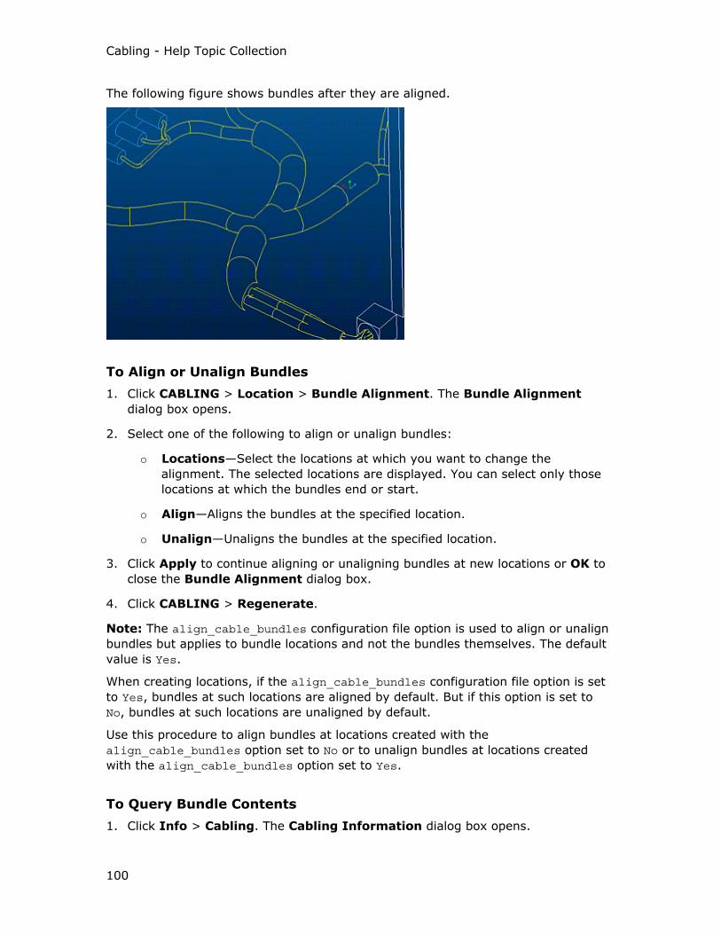
Cabling - Help Topic Collection
100
The following figure shows bundles after they are aligned.
To Align or Unalign Bundles
1. Click CABLING > Location > Bundle Alignment. The Bundle Alignment
dialog box opens.
2. Select one of the following to align or unalign bundles:
o Locations—Select the locations at which you want to change the
alignment. The selected locations are displayed. You can select only those
locations at which the bundles end or start.
o Align—Aligns the bundles at the specified location.
o Unalign—Unaligns the bundles at the specified location.
3. Click Apply to continue aligning or unaligning bundles at new locations or OK to
close the Bundle Alignment dialog box.
4. Click CABLING > Regenerate.
Note: The align_cable_bundles configuration file option is used to align or unalign
bundles but applies to bundle locations and not the bundles themselves. The default
value is Yes.
When creating locations, if the align_cable_bundles configuration file option is set
to Yes, bundles at such locations are aligned by default. But if this option is set to
No, bundles at such locations are unaligned by default.
Use this procedure to align bundles at locations created with the
align_cable_bundles option set to No or to unalign bundles at locations created
with the align_cable_bundles option set to Yes.
To Query Bundle Contents
1. Click Info > Cabling. The Cabling Information dialog box opens.

Cabling
101
2. Under Information Type, click Physical Routing.
3. Click Bundle Items.
4. Select a bundle to query. The bundle contents are displayed in the
INFORMATION WINDOW.
5. Click Close to close the Cabling Information dialog box.
To Extract Cables from a Bundle
1. Click CABLING > Modify > Mod Bundle. The SELECT dialog box opens.
2. To ensure that you select the correct bundle, click or Edit > Find, select the
required bundle, and click OK. The MOD BUNDLE menu appears.
3. Click Extract. The SEL BUNDLES menu appears. All the wires and cables inside
the selected bundle are available for selection.
4. Select the wires and cables that you want to extract or click Select All to select
all the wires and cables.
5. Click Done Sel to extract the selected wires and cables or all the wires and
cables from the selected bundle.
Using Overbraids
About Overbraids
The overbraid feature in Cabling provides a method of grouping multilevel cables and
understanding the hierarchy of a multilevel cable.
Consider three cables named C1, C2, and C3 as shown in the following figure.
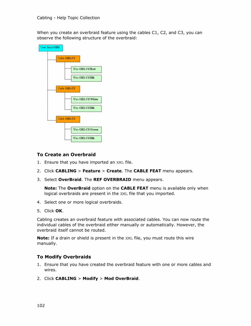
Cabling - Help Topic Collection
102
When you create an overbraid feature using the cables C1, C2, and C3, you can
observe the following structure of the overbraid:
To Create an Overbraid
1. Ensure that you have imported an XML file.
2. Click CABLING > Feature > Create. The CABLE FEAT menu appears.
3. Select OverBraid. The REF OVERBRAID menu appears.
Note: The OverBraid option on the CABLE FEAT menu is available only when
logical overbraids are present in the XML file that you imported.
4. Select one or more logical overbraids.
5. Click OK.
Cabling creates an overbraid feature with associated cables. You can now route the
individual cables of the overbraid either manually or automatically. However, the
overbraid itself cannot be routed.
Note: If a drain or shield is present in the XML file, you must route this wire
manually.
To Modify Overbraids
1. Ensure that you have created the overbraid feature with one or more cables and
wires.
2. Click CABLING > Modify > Mod OverBraid.

Cabling
103
3. Click or Edit > Find to select the overbraids by name. Cabling highlights all
the routed cables of the selected overbraid and prompts you to select two
locations.
4. Select two locations on the routed cables. Cabling overbraids the cables between
the two locations that you selected.
5. Repeat step 4 to overbraid as many sections of cables as required.
6. Click OK.
Autorouting
About Autorouting
Before autorouting the cables or wires, you must establish a logical reference to a
Pro/ENGINEER diagram file or a wire list text file in a supported format. Cabling
depends on the information in the wire list for the from-to connection information
that associates conductors and cables with individual entry ports (pins) on
connectors. In a logically referenced diagram, the ENTRY_PORT pin parameter must
be assigned to the corresponding coordinate system in the selected Cabling
assembly. If the ENTRY_PORT parameter is not defined in the logically referenced
diagram, the wires or cables cannot be autorouted.
After establishing a logical reference, you must set up a network using the CABLING
> Network Ops command. The network is defined by location points that are not
routed. You can specify location priorities in the network, for example, allowed or
disallowed, as needed for the network locations. Optionally, you can define paths
within the network and assign specific cables to them.
You can accept or reject the resulting routing. In case of errors in your autorouting
procedure, the failure information for the wires, cables, or incomplete conductors is
saved in the autoroute.fails file.
Use the CABLING > Network Ops > Route > Autoroute command to route the
selected wires or cables between their from and to connectors. The wires
automatically follow the shortest path through the network that you set up.
Note: You can use autorouting to complete a harness part without a logical
reference if you manually route a small piece of each cable from its last location to
its terminating connector. This establishes the connection of the wires, cables, or
cable conductors with the pins or connectors. The logical reference method is a faster
method.
To Autoroute Wires and Cables
1. If you have performed the setups described in the About Autorouting topic, you
can start the autorouting process.
2. Regenerate the harness before you autoroute.
Cabling - Help Topic Collection
104
3. Use the Cabling > Route commands to add cables and wires to the routing set
as you would for manual routing. The CABLE SEL, ADD CABLES, and ADD CBL
SEL menus appear.
4. Click Select from the ADD CBL SEL menu. The SELECT dialog box opens.
5. Select the cables or wires and click OK.
6. Click Done Sel in the CABLE SEL menu. The CBL ROUTE menu appears.
7. Click Autoroute. Cabling autoroutes the cables you have selected to be routed in
the network. The AUTOROUTING menu appears.
8. Click Rehighlight to display the autorouted cables in your assembly. The wires
and cables that you have added are highlighted.
9. Click Accept or Reject to accept or reject the resulting routing, respectively. In
case of errors in your autorouting procedure, the Autorouting Failure
Information dialog box opens.
10. Click More Info. The INFORMATION WINDOW opens and prompts you to look at
the autorte.fails file information. This error file contains the following
information:
o Wire number
o Explanation of the problem, for example, insufficient entry_port
information
o Suggested fix
Autorouting Bundles
Bundles by themselves cannot be autorouted as they do not extend completely from
connector to connector and thus have no From or To logical information. If you select
a bundle for routing and attempt to autoroute, the bundles are not autorouted. Use
the Route Wires command on the RMV BNDLE menu to autoroute the items
contained in the bundle, but not the bundle itself.
If you select the Ignore Wires command on the RMV BNDLE menu, the contents of
the bundle are not autorouted.
Autorouting to Splices
If you designate a splice as the connector for a wire, autorouting routes the wire to
the splice as it routes to any connector.
If the splice is not assembled, you can autoroute the wire with one connector and
one required location, and later insert the splice at the required location.
Tip: Autorouting through Components
Wires can be autorouted through components. There need not be any network
segment that contact two entry ports with an internal cable portion between them.
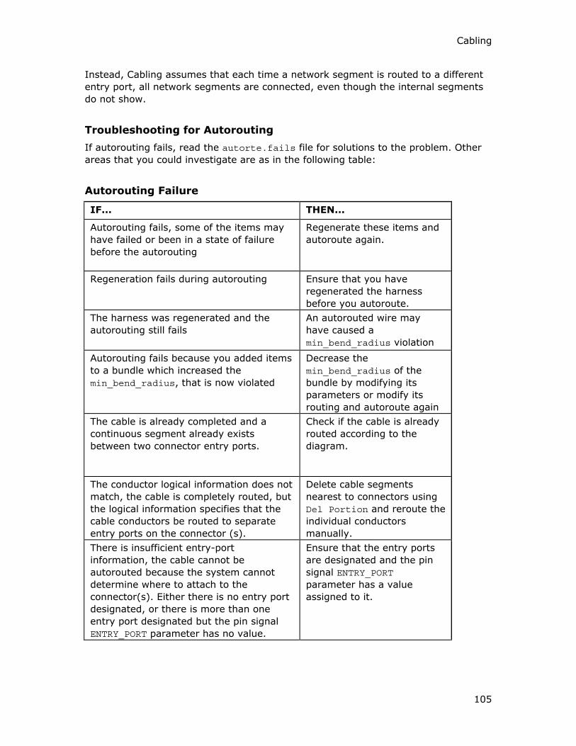
Cabling
105
Instead, Cabling assumes that each time a network segment is routed to a different
entry port, all network segments are connected, even though the internal segments
do not show.
Troubleshooting for Autorouting
If autorouting fails, read the autorte.fails file for solutions to the problem. Other
areas that you could investigate are as in the following table:
Autorouting Failure
IF... THEN...
Autorouting fails, some of the items may
have failed or been in a state of failure
before the autorouting
Regenerate these items and
autoroute again.
Regeneration fails during autorouting Ensure that you have
regenerated the harness
before you autoroute.
The harness was regenerated and the
autorouting still fails
An autorouted wire may
have caused a
min_bend_radius violation
Autorouting fails because you added items
to a bundle which increased the
min_bend_radius, that is now violated
Decrease the
min_bend_radius of the
bundle by modifying its
parameters or modify its
routing and autoroute again
The cable is already completed and a
continuous segment already exists
between two connector entry ports.
Check if the cable is already
routed according to the
diagram.
The conductor logical information does not
match, the cable is completely routed, but
the logical information specifies that the
cable conductors be routed to separate
entry ports on the connector (s).
Delete cable segments
nearest to connectors using
Del Portion and reroute the
individual conductors
manually.
There is insufficient entry-port
information, the cable cannot be
autorouted because the system cannot
determine where to attach to the
connector(s). Either there is no entry port
designated, or there is more than one
entry port designated but the pin signal
ENTRY_PORT parameter has no value.
Ensure that the entry ports
are designated and the pin
signal ENTRY_PORT
parameter has a value
assigned to it.

Cabling - Help Topic Collection
106
IF... THEN...
The logical and physical entry ports do not
match, a cable may only attach to two
connector locations (except when routing
through a splice). For the cable above, the
system cannot determine the correct From
and To connectors because there are two
correct logical connectors in addition to
one or two physically routed cable
segments routed from other connectors.
Ensure that the names of the
logical and physical entry
ports for both diagram and
cabling match.
No path through the network is found, the
location priorities may be set so that the
required or disallowed locations prevent a
complete path from existing. Autorouting
with a network that is not all connected
may mean there is no path between
connectors. Also, the tangencies of the
existing network locations do not allow
routing between connectors.
Add additional network
segments and autoroute
again.
The cable has too many ends to route too
many independent segments touching the
network for the system to determine
which should be used for routing.
Ensure that the cable does
not contain more than one
manually routed segment.
Using the MBR Failure Diagnostic
If autorouting fails because of an MBR (Minimum Bend Radius) violation, the
segment where the violation occurred is highlighted, and a new dialog box opens.
This dialog box provides tools to collect more information about the failure and how
to fix the failure.
Use this dialog box to:
• Highlight failures in a wire
• Route the wire and ignore failures
If the routing of the wire segments fail upon regeneration, fix the failure using
Resolve options, or fix it before regeneration.
• Select not to route the failed wire.

Cabling
107
Autorouting Networks
About Routing with Networks
A network is a series of locations that defines default paths for autorouted cables.
Use the Network Ops > Route commands to add locations as you would when
routing a cable. The difference is that you do not have a cable attached for the path
you are defining. The path is represented by a dotted line.
A network is associated with the cables of the active harness. Cables assigned to
other harnesses in the assembly are not routed until their harnesses are made
active. A network created in one harness may be made available for routing by
another harness if you designate the network as shared. A network is associated
with the harness part in which it is created. If you want to make a network available
to route more than one harness part, you can share the network between selected
harness parts. Sharing makes a network created in a non-active harness available to
the active harness.
You can copy a network or network branches at a specified offset distance from the
original network. The original locations forming the network are copied at the offset
distance. The existing network portion is also copied at the new locations.
Network Properties
When you add network locations, you can also assign priorities to them to further
define the autorouting process.
Network bundles and sheathing are created in the same way as other bundles,
except that they exist along a branch of the network. Cabling does not automatically
create bundles for the network, but you can assign bundles and sheathing to network
segments even if no wires are present yet.
Sheathing on the network can be used for space planning for the harness in early
stages of the design.

Cabling - Help Topic Collection
108
Assigning Location Priority for Network Locations
To control the path in the network that autorouting uses, you can assign the
following priorities to network locations.
Type Description
Primary (Default) These network locations are used whenever
possible.
Required Forces all wires being autorouted to pass
through the specified location or locations in
the same direction directions, even if this does
not create the shortest path for each wire.
This priority is used to handle wires that are
routed through a common splice or to a splice
that is to be inserted. You can also use this
priority to ensure that wires travel through a
specific hole or duct.
Disallowed Disallowed network locations cannot be used
for autorouting. You can avoid overfilling of
channels, interference with a fixed size hole in
a bulkhead, or creation of loops in an
individual harness.
Secondary A network location that is used for autorouting
only if no complete path using primary
locations is available.
To Use Location Priority for Autorouting
1. Click CABLING > Network Ops. The NETWORK OPS menu appears.
2. Select the type of priority you want to assign.
o Required Loc
o Primary Loc
o Secondary Loc
o Disallow Loc
o Reset All
If you click the Required Loc command, the REQD LOCS menu appears. Select
one of the following options:
Select—Select locations through which all autorouted cables must pass. You can
have multiple required locations of this type.

Cabling
109
Optimize—System finds the shortest paths with at least one common location
for autorouted items. This location becomes a required location after autorouting
so that you know the location that was selected. This removes all previously set
required priority locations.
Put on Wire—System finds the best and shortest paths with a common location
on a selected wire. This location becomes a required location after autorouting so
that you know the location that was selected. This removes all previously set
required priority locations.
Click Reset All to reset all network locations used for autorouting to the default
primary location.
Note: Modifying the location priority only affects subsequent autorouting operations.
Previously autorouted wires are not affected.
To Define the Tangency Direction at Network Branches
1. Click Cabling > Network Ops. The NETWORK OPS menu appears.
2. Define the tangency of the network branch by using one of the following
commands:
Flip Direction—Flips the direction of the network branch at the selected location
or locations and also fixes the tangency direction.
Fix Tangency—Fixes the tangency of the network branch at the selected
location or locations. The branch direction remains unchanged even if the shape
of the network changes.
Display Tangency—Displays an arrow to indicate the direction of the tangency
for all the network branch locations that have a fixed tangency.
Clear Fixed Tangency—Clears the fixed tangency for the selected location or
locations.
Clear All—Clears the fixed tangency from all the network locations. The branches
revert to the shape defined by the system, depending on the geometry of the
main network segment.
3. Select the network branch location or locations for which you want to modify the
tangency direction.
To Modify Network Locations
1. Click Cabling > Network Ops > Route.
2. Use the CBL ROUTE commands to edit location placing or type.
You can add, modify, or remove locations from the network.
Note:
• If assembly references are updated, so does the network shape.

Cabling - Help Topic Collection
110
• To delete a network segment, use the CBL ROUTE > Del Portion command. If
you delete a network, the cable locations remain and the cable/network color
changes.
To Copy a Network
1. Click CABLING > Network Ops > Route > Offset.
2. Select three straight edges or a coordinate system. No tangency is enforced at
the location.
3. Specify the network direction.
4. Click Specify Portion to select a portion of the cable that you want to copy
using the SELECT dialog box.
5. Specify the reference directions and network portions.
6. Click Make Locs to begin the creation of offset locations based on the given
references.
7. An arrow appears for each direction. Type the offset value for each of the three
directions. A new network is created that is offset from the original.
8. To create another network at a different offset value from the original network,
click Make Locs again.
9. When you have finished creating copied networks, and want to return to the CBL
ROUTE menu, click Done/Return.
Note:
• The copied network offset locations are parametric with the existing network
locations. If the distances between the locations of the original network are
changed, the distances between the locations of the copied network change
similarly.
• The offset between the original network and the copied network is controlled by a
single dimension that can vary.
• You can use Modify > Make Indep to make the dimensions of each copied
location independent of the network.
• If the original network is deleted, the copied network is not deleted as the copy is
independent of the original network.
To Share Networks Between Harness Parts
1. Click Cabling > Network Ops > Share. You are prompted to select the harness
associated with the network you want to share with the current harness.
2. When you select the harness, the model is regenerated and the locations in the
shared network are available to the current harness. To directly connect networks
across shared harness parts, use the Connect command. To undo the sharing,
use the Unshare command.

Cabling
111
Sharing makes a network created in a non-active harness available to the active
harness
About Network Paths
After you have defined an autorouting network, you can define paths within the
network and associate specific cables or wires with them to further control the
autorouting. In the following figure, a part of the network is defined as a path.
When you define a path, you are prompted to name it. The name is attached to the
path as a note.
To associate a cable or wire with the path, attach a parameter named use_path to
the cable or wire and use the path name as the value.
If a path conflicts with other network location priorities, maximum diameter
restrictions, or other autoroute restrictions, the autorouting of the wire fails.
Autorouting the wire fails, for example, if the specified path contains disallowed
locations.
As a network path acts like any other cable, you can modify it so that some portion
of the path may no longer be on the network. If both ends of a path are on the
network, autorouted cables follow the path (leaving the network and returning). If
only one end of a path is on the network, that path is ignored.
To Define and Edit Network Paths
1. Ensure that an autorouting network exists.
2. Click CABLING > Network Ops > Define Path.
3. Select a start and end location to define the path.
4. Click Done Sel. You are prompted to name the path.
5. At the prompt, type a name and press ENTER. The path is created and the name
is attached to a note on the path.
6. To extend or remove the path, click Network Ops > Extend Path or Network
Ops > Rename Path.
To Associate Connections With Network Paths
To specify that a wire or cable must use a predefined network path, add a use_path <path name> parameter and its value to the wire or cable feature.
Note: To use a different name for the parameter, use the
autoroute_path_param_name configuration option.
Cabling - Help Topic Collection
112
Adding Cabling Cosmetic Features
About Cabling Cosmetic Features
The three types of cabling cosmetic features are tie wraps, markers, and tape. Each
is described below.
Note: When creating cosmetic features that represent tie wraps, markers, and tape,
you can only select cables and locations that belong to the active harness.
Tie wraps, markers, and tape features have feature parameters. You can assign
user-defined colors to the Cabling cosmetic features. Use the Appearance Editor
dialog box to change the colors of the cosmetic features. By default, all cosmetic
features are assigned the system color, Sheetmetal. You can access all tie wrap and
marker feature parameters in Pro/REPORT through the &asm.mbr.cblprms category.
Tie Wraps
A tie wrap is used to hold one cable or several cables together. The representation
for the tie wrap is as follows:
• In centerline cable display, a circle with a circumference that corresponds to the
length of the tie wrap.
• In thick cables environment, a cylinder that shows the appropriate circumference,
thickness, and width.
Tie wraps have no required parameters. However, if you specify a name during tie
wrap creation, Cabling implements it as a parameter in the parameter file. You can
also assign user-defined parameters to tie wraps using the Electrical Parameters
dialog box.
Tape Feature
Use this cosmetic feature to show where wires are taped to a thicker portion of the
harness in the cabling assembly. The tape feature is located at a single location
whereas tape sheathing is wrapped around entire bundle segments of the harness.
As in other cabling features, each tape feature has its own set of feature parameters.
Tape features have three required feature parameters:
• NAME
• NUM_OF_WINDS
• SPOOL
Markers
Markers represent shrink wrap tubing that is placed on a cable during the
manufacturing process to identify the cable for assembly, maintenance, and repair
purposes. Cabling represents markers as cylindrical features around the selected
cable with a name tag to identify the marker. The tag switches on and off with the
display of the datum point.
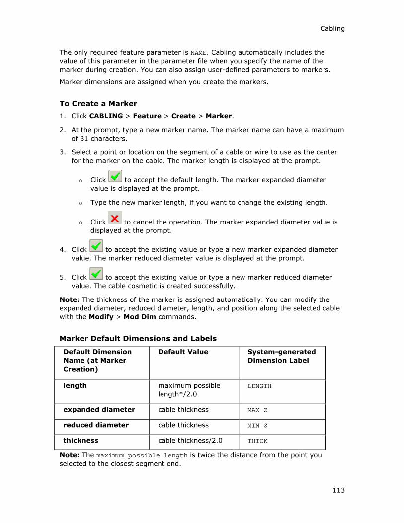
Cabling
113
The only required feature parameter is NAME. Cabling automatically includes the
value of this parameter in the parameter file when you specify the name of the
marker during creation. You can also assign user-defined parameters to markers.
Marker dimensions are assigned when you create the markers.
To Create a Marker
1. Click CABLING > Feature > Create > Marker.
2. At the prompt, type a new marker name. The marker name can have a maximum
of 31 characters.
3. Select a point or location on the segment of a cable or wire to use as the center
for the marker on the cable. The marker length is displayed at the prompt.
o Click to accept the default length. The marker expanded diameter
value is displayed at the prompt.
o Type the new marker length, if you want to change the existing length.
o Click to cancel the operation. The marker expanded diameter value is
displayed at the prompt.
4. Click to accept the existing value or type a new marker expanded diameter
value. The marker reduced diameter value is displayed at the prompt.
5. Click to accept the existing value or type a new marker reduced diameter
value. The cable cosmetic is created successfully.
Note: The thickness of the marker is assigned automatically. You can modify the
expanded diameter, reduced diameter, length, and position along the selected cable
with the Modify > Mod Dim commands.
Marker Default Dimensions and Labels
Default Dimension
Name (at Marker
Creation)
Default Value System-generated
Dimension Label
length maximum possible
length*/2.0
LENGTH
expanded diameter cable thickness MAX Ø
reduced diameter cable thickness MIN Ø
thickness cable thickness/2.0 THICK
Note: The maximum possible length is twice the distance from the point you
selected to the closest segment end.

Cabling - Help Topic Collection
114
To Create a Tape Feature
1. Click CABLING > Feature > Create > Tape.
2. At the prompt, type a unique name for the tape feature.
3. Select an existing tape spool on which to base the new tape feature.
4. Click Create, if a tape spool does not exist yet or you want to create a new tape
spool.
5. At the prompt, type a unique name for the tape spool. The SPOOL NAMES menu
appears.
6. Click Create or select an existing spool.
7. If you click Create, at the prompt type a new name for the spool. The Electrical
Parameters dialog box appears with the default spool parameters.
8. Modify the required spool parameter values.
9. Click Apply and then OK in the Electrical Parameters dialog box.
10. At the prompt, type the number of times the tape is to wind around the cable or
set of cables. The default is 2 times.
11. Select a cable location to use as center for the new tape feature. Cabling wraps
all items at the selected location with the tape feature.
Note: There are no dimensions to modify in a tape feature, as the size is determined
by the tape spool parameters. You can modify the tape feature using the Electrical
Parameters dialog box only.
To Create a Tie Wrap
1. Click CABLING > Feature > Create > Tie Wrap.
2. At the prompt, type a new tie wrap feature name.
3. Select a location or point on the segment of the cable to use as a center for the
tie wrap. The selected segment of the cable is highlighted. The dimension that
locates the tie wrap is created automatically from the start of the cable portion,
and all other dimension values are assigned.
o If a location is chosen, the tie wrap wraps around all cables at that location.
o If a point along a segment portion is chosen, only the selected item is
wrapped by the tie wrap.
The default tie wrap dimension values are assigned automatically as follows:
o THICK—cable thickness / 4.0
o WIDTH—cable thickness / 4.0
o LENGTH—cable thickness * pi
Note: The tie wrap length is not used to calculate the tie wrap diameter.
Cabling
115
To Modify Cosmetic Feature Dimensions
1. Click CABLING > Modify > Mod Dim.
2. Select the required feature, the feature’s dimensions appear.
3. Modify the dimensions press ENTER.
Note: The Datum Point display must be set in the Environment dialog box to
display the tape, tie wrap, and marker labels and the location where they are placed.
To Modify Cosmetic Feature Parameters
1. Click CABLING > Modify > Cosmetics.
2. Select the required cosmetic feature (tie wrap, tape, or a marker) you want to
edit and middle-click. The Electrical Parameters dialog box opens.
3. Edit the parameters of the required cosmetic features using the Electrical
Parameters dialog box.
Exporting Cabling Geometry
To Export Cabling Geometry
You can export the complete geometry of wires and cables, or just the centerlines,
from a Cabling assembly to IGES and other common formats.
1. Click File > Save a Copy.
2. Select the export format in the Type box. The Export Environment dialog box
for the selected environment opens. If the functionality is supported in the
selected format:
o Select Export Cable Surfaces to export the cables as surfaces (as seen in
thick Cable mode.)
o Select Datum Curves and Points to export cabling harness as centerlines.
Select neither to exclude any cabling geometry information from the export.
3. Click OK.

Cabling - Help Topic Collection
116
Pro/Report Parameters
Pro/REPORT Parameters for Assemblies
Use the following Pro/REPORT parameters for cabling assemblies:
&asm.mbr.connprm.<User Defined>—Lists the values of the specified user-defined
parameter for each connector.
&asm.mbr.connprm.name—Lists the reference designators of connectors used in the
assembly.
&asm.mbr.connprm.pin.entry_port—Lists the entry port of the pin of the specified
user-defined parameter for each connector.
&asm.mbr.connprm.pin.name—Lists the pin names for each connector in the
assembly.
&asm.mbr.connprm.pin.run.<User Defined>—Lists the specified user-defined
parameters for wires, cables, or bundles connected to each connector pin.
&asm.mbr.connprm.pin.run.cond.<User Defined>—Lists the user-defined
parameters of the given conductor of wires, cables, or bundles connected to each
connector pin.
&asm.mbr.connprm.pin.run.cond.color—Lists the color of the given conductor of
wires, cables, or bundles connected to each connector pin.
&asm.mbr.connprm.pin.run.cond.name—Lists the name of the given conductor of
wires, cables, or bundles connected to each connector pin.
&asm.mbr.connprm.pin.run.cond.strip.len—Lists the strip length of a wire
attached to a specified pin connector.
&asm.mbr.connprm.pin.run.len—Lists the length of wires, cables, or bundles
connected to each connector pin.
&asm.mbr.connprm.pin.run.name—Lists the names of wires, cables, or bundles
connected to each connector pin.
&asm.mbr.connprm.pin.run.spool.<User Defined>—Lists the specified user-
defined spool parameters of wires, cables, or bundles connected to each connector
pin.
&asm.mbr.connprm.pin.run.spool.name—Lists the spool names of wires, cables, or
bundles connected to each connector pin.
&asm.mbr.connprm.pin.signal.name—Lists the signal names of each connector pin.
&asm.mbr.connprm.pin.signal.type—Lists the signal types of each connector pin.
&asm.mbr.connprm.pin.term.<User Defined>—Lists the specified user-defined
parameters used in the terminators attached to connector pins.
&asm.mbr.connprm.pin.term.name—Lists the terminator names attached to
connector pins.

Cabling
117
Pro/REPORT Parameters for Terminators
Use the following terminator-related parameters in Pro/REPORT:
&harn.run.cond.from—Lists the terminator name that every wire and cable is
routed from, in the harness.
&harn.run.cond.to—Lists the terminator name that every wire and cable is routed
to, in the harness.
&harn.term.qty—Lists the numbers of every terminator used in the harness.
&harn.term.name—Lists all the terminator names used in the harness.
&harn.term.<User Defined>—Lists the specific user-defined parameter for every
terminator used in the harness.
Note: The parameters &harn.term.qty, &harn.term.name, and &harn.term.<User Defined> must have the harness part as the drawing model.
Harness Related Pro/REPORT Parameters
You can use several Pro/REPORT parameters in Cabling, cabling assemblies and flat
harnesses. You can also use an item's parameters as user-defined parameters in a
Pro/REPORT table.
Perform the following steps to set the model before creating a table. Using this table,
you can access the Pro/REPORT parameters.
1. Open the required drawing and click File > Properties. The FILE PROPERTIES
menu appears.
2. Click Drawing Models. The DWG MODELS menu appears.
3. Click Add Model to add a new part or assembly to the drawing. The selected
model becomes the default or current model.
4. If you have added multiple parts or assemblies, click Set Model to set the
required harness part or flat assembly as the current model.
The report parameters in the following table use cond to refer to all wires and cable
conductors in a harness and run to refer to all wires and cables in a harness. The
term from/to indicates that the parameter exists for both From and To directions.
The User Defined category indicates that you can specify user-defined parameters
and also system parameters.
For example, although &harn.run.spool.color is not specifically defined, you can
specify &harn.run.spool.UserDefined and type the system parameter color.

Cabling - Help Topic Collection
118
Pro/REPORT Parameters
Parameter Name Definition
&asm.mbr.cblprm.User Defined Lists the specified user-
defined parameter in the
cabling components
&asm.mbr.cblprms.name Lists names of all the
user-defined parameters
in the cabling
components
&asm.mbr.cblprms.value
Lists values of all user-
defined parameters in
the cabling components
&asm.mbr.connprm.name Lists reference
designators of
connectors in the
assembly
&asm.mbr.connprm.pin.name Lists names of pins for
each connector in the
assembly
&asm.mbr.connprm.pin.run.cond.color Lists the color of the
wires and conductors
connected to each
connector pin
&asm.mbr.connprm.pin.run.cond.name Lists name of the
conductors and wires
connected to each pin
&asm.mbr.connprm.pin.run.cond.strip.len Lists the strip length of
wires and conductors
attached to each pin
&asm.mbr.connprm.pin.run.cond.User Defined Lists the specified user-
defined parameter in
conductors or wires,
connected to each pin
&asm.mbr.connprm.pin.run.len Lists the length of wires
and cables connected to
each pin

Cabling
119
Parameter Name Definition
&asm.mbr.connprm.pin.run.name Lists the names of wires,
cables, or bundles
connected to each
connector pin
&asm.mbr.connprm.pin.run.spool.name
Lists spool names of
wires or cables
connected to each
connector pin
&asm.mbr.connprm.pin.run.spool.User Defined
Lists the specified user-
defined spool parameter
of wires and cables
connected to each pin
&asm.mbr.connprm.pin.run.UserDefined Lists the specified user-
defined parameter for
wires and cables
connected to each pin
&asm.mbr.connprm.pin.signal.name Lists signal names of
each pin
&asm.mbr.connprm.pin.signal.type Lists signal types of each
pin
&asm.mbr.connprm.pin.term.name Lists the terminator
name of each pin
&asm.mbr.connprm.pin.term.UserDefined Lists the user-defined
parameters set for the
terminators
&asm.mbr.connprm.UserDefined
Lists values of the
specified user-defined
parameter for each
connector
&asm.mbr.connprm.pin.entry_port
Lists the entry port
parameter of each pin
for each connector

Cabling - Help Topic Collection
120
Parameter Name Definition
&asm.mbr.connprm.pin.signal.UserDefined
Lists the specified user-
defined parameter for
each pin
&asm.mbr.cparams.name Lists the names of all
user-defined parameters
in the assembly
components
&asm.mbr.cparams.User Defined Lists the specified user-
defined parameters used
in the assembly
components
&asm.mbr.cparams.value Lists the values of all
user-defined parameters
in an assembly
component
&asm.mbr.name Lists the names of
assembly members
&asm.mbr.param.name Lists the names of all
user-defined parameters
in an assembly member
&asm.mbr.param.value Lists the values of all
user-defined parameters
in an assembly member
&asm.mbr.type Lists the type (part,
assembly, or terminator)
of an assembly member
&asm.mbr.User Defined Lists the specified user-
defined parameter for
the respective assembly
components
&harn.run.cond.color
Lists the color for every
routed wire or cable in
the harness
&harn.run.cond.from/to.conn.name
Lists connector reference
designators that every
wire or cable conductor
is routed from or to

Cabling
121
Parameter Name Definition
&harn.run.cond.from/to.pin.name
Lists pin names that
every wire or cable
conductor is routed from
or to
&harn.run.cond.from/to.pin.entry_port Lists the pin entry port
for every wire or cable
conductor
&harn.run.cond.from/to.pin.sig.name Lists the pin signal name
for every wire or cable
conductor
&harn.run.cond.from/to.pin.sig.type Lists the pin signal type
for every wire or cable
conductor
&harn.run.cond.from/to.pin.sig.UserDefined Lists the specified user-
defined pin parameter
for every wire or cable
conductor
&harn.run.cond.from/to.strip.len Lists the strip length of
each wire or cable
conductor
&harn.run.cond.from/to.term.name Lists the terminator
name for every wire or
cable conductor
&harn.run.cond.name Lists every routed wire
or cable conductor in the
harness
&harn.run.cond.User Defined Lists the specified user-
defined parameter for
every wire or cable
conductor in the harness
&harn.run.from/to.conn.name Lists connector reference
designators that every
wire and cable is routed
from or to

Cabling - Help Topic Collection
122
Parameter Name Definition
&harn.run.from/to.conn.User Defined Lists the specified
connector user-defined
parameter that every
wire or cable is routed
from or to
&harn.run.len Lists lengths of routed
wires or cables
&harn.run.name Lists names of routed
wires or cables
&harn.run.spool.name Lists the spool name for
every routed cable or
wire
&harn.run.spool.User Defined Lists the specified user-
defined spool parameter
for every wire or cable
&harn.run.subharn.name Lists subharness names
used
&harn.run.User Defined Lists the specified user-
defined wire, cable or
bundle parameter for
every harness
&harn.term.name Lists all terminator
names used in the
harness
&harn.term.qty Lists the numbers of
every terminator
instances used in the
harness
&harn.term<User Defined>
Lists the specified user
defined parameter for
every terminator used in
the harness

Cabling
123
Parameter Name Definition
&harn.spool.len
Lists the total lengths of
routed wire spools and
cable spools
&harn.spool.name
Lists the wire or cable
spool names used
&harn.spool<User Defined>
Lists the specified user
defined parameter for
every wire or cable spool
used
The following conditions apply:
Report Parameter Active Model Attribute
&harn... Harness part NA
&asm.mbr.cblprm(s)... 3D assembly Cable Info
&asm.mbr.connprm... 3D assembly/Flat
assembly
NA
Note: The Cable Info attribute is available only when you select at least one cable
parameter in the repeat region.
To assign a different model to a region:
1. Click Table > Repeat Region. The TBL REGIONS menu appears.
2. Click Model/Rep to display a different model or simplified representation to
control a region. If you change the model associated with the repeat region, the
repeat region is populated with the respective data.
3. Select a region. The Open dialog box opens.
4. Select a new part or assembly to be associated with the repeat region.

Cabling - Help Topic Collection
124
Glossary
Glossary of Terms
Term Definition
Harnesses A harness is a cable part you create within the assembly
context and has a complete information of wires, cables,
and cosmetic features in a cabling assembly. One assembly
can contain several harnesses, and one harness can contain
different cables, as connected or unconnected segments.
Bundles A bundle is made up of one or more cables, wires, or other
bundles that are represented as sheathed or wrapped.
Bundles are created from spools that carry properties like
min_bend_radius, color, and bundle_type (round or flat
shape). You must add cables to a bundle after you have
added them to the routing set and before you begin to
route.
Channels Channels are conduits for defining direction or for
terminating cables to a conductive strip as a ground or as
part of the live circuit. Channels are also the basis for
modifying cable or network locations in cross sections.
Connectors Connectors are parts that have parameters you can use to
define the beginning and end of cables. You must designate
a part as a connector, and define one or more coordinate
systems to use as an entry port before you can route the
wire or cable to it.
Custom
components
Custom components are similar to spliced components
except they do not use parameters. You can use custom
components in place of cabling components that do not
need a reference designator.
In line
connectors
In line connectors are pairs of male-female connectors
which break the cable into two physical cables but maintain
signal continuity between them.
Locations Locations are the user-defined points within the assembly
that describe the path that cable routing should follow.
Locations can be free-floating on one selected surface.
Network A network is a string of locations without cables attached to
them that define a path for autorouting. Networks are not
cable specific; any number of cables or wires can share a
network.

Cabling
125
Term Definition
Network Paths A network path is a portion of the network with a name,
defined between two locations, and passes through a series
of locations in an network. This path can be assigned to a
specific cable using the use_path config option.
Splice
components
The splice components are components added somewhere
along the length of a cable. The cable name and length
from connector to connector is not affected after the splice
component is installed.
Through
Splice
Added along the length of the cable and will not split the
cable.
Butt Splice Splits the cable into two parts
Spools A spool is similar to an actual spool from which you roll off
an amount of cable or wire, as needed. Spools are
collections of parameters like color, gauge, and so on that
you reference when you create individual wires and cables.
When you edit the spool, the edits are passed to the wires
or cables that were created from it.
Wire spools Contains the basic descriptive parameters such as color,
thickness, and so on for one conductor or import them.
Cable spools Describes the cable sheath and certain number of
conductors. You must create spools in the cabling assembly
or import them from a logical reference before you route
the wire or cable. Spool files are saved with the .spl
extension.


127
Index
A
Autorouting Cables
Bundles .................................. 104
displaying cables .........7, 9, 69, 103
Overview ................................ 103
Process................................... 103
through components ................ 104
troubleshooting problems.......... 105
using splices ........................... 104
Autorouting Cables ....... 103, 104, 105
B
Bundle
Autorouting........................ 93, 104
create on .................................. 94
creating an unrouted bundle........ 93
extracting cables ..................... 101
Overview .............................91, 92
Bundle ...............91, 93, 99, 100, 104
C
Cable Colors
setting at the spool level............. 32
Cable Colors .................................. 8
Cable Component
autodesignating....................47, 49
designating ............................... 46
replacing ....................... 40, 53, 54
undesignating............................ 49
Cable Component ....................46, 49
Cable Display
Centerline................................... 7
Parameters................................69
Thick ......................................7, 9
Cable Display................................. 7
Cable Information
Dialog Box.................................81
Cable Information .........................81
Cable Paths Setup .........................39
Cable Routing
following an existing cable ...........77
routing through an axis ...............78
selecting cables to route..............75
straight or rounded between
locations.................................75
through a cable location point77, 83,
84
Cable Routing ....................73, 75, 84
Cable Strip Length Table
creating ....................................36
Cable Strip Length Table ................36
Cables
add or remove from routing set....76
autorouting .............................103
clearance check..........................82
color control overview.................. 8
constraining thickness at locations88
creating features ........................32
deleting segments ......................81
extracting from bundles ............101
modifying locations.....................87
Relations...................................80

Cabling - Help Topic Collection
128
selecting cables to route ............. 75
setting cable to fixed length ........ 80
setting color value for................. 32
splitting ...............................36, 77
Cables....8, 28, 32, 36, 76, 77, 80, 88,
103
Cabling Bundles
adding along a routed path ....81, 93
adding cables to ........................ 98
Overview .................................. 91
Cabling Bundles.......................93, 98
Cabling Channels
Conduct.................................... 90
Direction................................... 90
Ground..................................... 90
Overview .................................. 90
Cabling Channels.......................... 90
Cabling Components
autorouting ............................. 104
editing parameters for ................ 40
Types....................................... 37
Cabling Components ................37, 40
Cabling Conductors
defining in the cable spool........... 72
routing individual conductors.72, 74,
83
Cabling Conductors ..................72, 83
Cabling Connectors
autodesignating......................... 49
changing designation.................. 49
replacing .................................. 54
Cabling Connectors ..................49, 54
Cabling Cosmetic Features
creating markers ......................113
creating tape features ...............114
creating tie wraps.....................114
Marker ....................................113
modifying dimensions of............115
Cabling Cosmetic Features ....112, 114
Cabling Custom Components
redefining placement ..................53
Cabling Custom Components ..........53
Cabling Dimensions
fix length ..................................36
measure between locations.... 36, 80
modify ......................................36
modifying..................................87
Cabling Dimensions ................. 36, 87
Cabling Display Environment
setting up................................... 7
Cabling Display Environment ........... 7
Cabling Entry Ports
assigning to pins ........................57
connector parameter...................56
designating entry ports ...............56
routing wires .............................56
Cabling Entry Ports.................. 56, 57
Cabling Geometry
exporting ................................115
Cabling Geometry .......................115
Cabling Glossary .........................124
Cabling Locations
adding locations to routed cables..89

Index
129
constraining cable thickness at .... 88
creating a dependent location...... 84
creating offset locations.............. 85
defining node size ...................... 89
editing in channel cross section.... 91
modifying location...................... 86
modifying packing...................... 89
placing in channels..................... 90
redefining location ..................... 87
removing .................................. 89
Cabling Locations .. 84, 86, 87, 88, 89,
91
Cabling Networks
about ..................................... 107
assigning location priority ......... 108
controlling path ....................... 108
copying a network ................... 110
modifying network locations ...... 109
sharing between harnesses ....... 110
Cabling Networks................. 108, 110
Cabling Parameters
flip cable ends ........................... 69
for components ....................38, 39
list of parameters 22, 24, 27, 33, 50,
51, 70, 95
modifying ...................... 40, 53, 66
Pro/REPORT ..................... 116, 117
specifying parameter values ..66, 67,
68
to display.................................. 69
updating................................... 11
wire strip .................................. 36
Cabling Parameters .11, 36, 38, 53, 65
Cabling Splices
inserting ............................. 42, 44
modifying at locations .................89
Cabling Splices .............................42
Cabling Spools
adding from logical reference .......32
creating ....................................28
writing spools ............................31
Cabling Spools ..............................28
Cabling Terminator Table
assigning a terminator ................61
creating ....................................59
modifying..................................60
reading .....................................60
removing ..................................61
renaming ..................................60
using .................................. 58, 61
writing ......................................60
Cabling Terminator Table ...............58
Cabling Wirelists
exporting ..................................16
importing ............................ 11, 16
Cabling Wirelists ..................... 11, 16
Configuration File Options
about configuring Cabling ............. 3
cabling configuration options.. 4, 5, 6
Configuration File Options ............... 3
D
Datum Features
creating for harness parts............19

Cabling - Help Topic Collection
130
Datum Features ........................... 19
Diagramming Diagrams
about logical referencing........10, 11
logically referencing to cables .32, 35
Diagramming Diagrams................. 10
H
Harnesses
adding to a family table .........20, 21
checking global clearance............ 82
copying .................................... 18
creating......................... 17, 18, 41
creating subharnesses ................ 19
deleting ...............................18, 42
modifying units.....................17, 41
setting up ................................. 16
Harnesses ........16, 17, 18, 41, 42, 82
L
Logical Reference
adding a wire from..................... 35
comparing data ......................... 11
exporting data.................... 16, 115
from diagram to cabling.........10, 35
importing a wirelist .................... 16
on selected layers .................10, 32
updating cable parameters with....11
Logical Reference ......... 10, 11, 16, 35
P
Pro/REPORT Parameters
for assemblies..........................116
for terminators.........................117
harness related Pro/REPORT
parameters ...........................117
Pro/REPORT Parameters........116, 117
S
Spools
about cabling spools ...................21
list ...........................................32
modify ................................ 29, 32
remove .....................................31
rename .....................................30
write.........................................31
Spools .........................................21
W
Wirelist in Diagrams
Neutral Format...........................12
Wirelist in Diagrams ......................12
Wires
grouping in cable........................56
Wires...........................................56


