Multiposition AHU AC777KNZDCH/AA Air Conditioner installation manual imagine the possibilities Thank you for purchasing this Samsung product. EN ES FR jhj vkt }Tho|ptuv{jvkllunU Z YWX_TW^TZX 㝘䟸 XaZ^aX^
Transcript
Multiposition AHUAC KNZDCH/AA
Air Conditionerinstallation manual
imagine the possibilitiesThank you for purchasing this Samsung product.
EN ES FR
2
Safety Precautions
WARNING
WARNING
General information
Contents2
4
7
12
13
17
24
33
41
3
ENGLISH
Installing the unit
IMPORTANT
Power supply line, fuse or circuit breaker
4
Safety Precautions
CAUTION
General Information
NOTE
ENGLISH
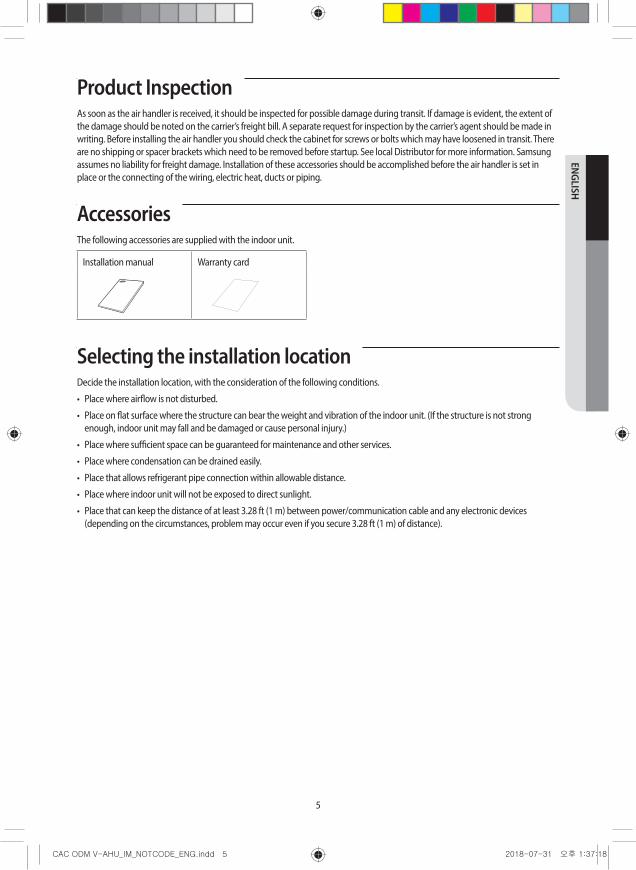
Product Inspection
Accessories
Selecting the installation location
Selecting the installation location
Dimensions
5
BOTTOMs
TOP
LEFT SIDE RIGHT SIDEFRONT
DIMENSIONAL DATA MULTI-POSITION AIR HANDLER
A B C D E F G H J K L M N P R
NOTE
No. Description
1
2
345
7
ENGLISH
Indoor unit installation
Location
Drain pipe installation
H H
Clearance - Access for service
30" minimum
Right side of unit
Vertical installation Horizontal installation
Indoor unit installation
Return air requirements
0" 0"
Return Air Requirements
For A/C and HP Air Handlers 1/3 HP Blower Motor
For A/C and HP Air Handlers 1/2 HP Blower Motors
For A/C and HP Air Handlers with Electric Heat use 3/4 HP Blower Motor
9
ENGLISH
Return air requirements
Closet Wall
Typical Closet Installations
Upflow Accessory Filter Box Kit
NOTE
ADJUSTMENT KNOB FOR 1" OR 2" FILTER
ADJUSTMENT KNOB FOR 1" OR 2" FILTER
Accessory Air Filter Box for 1” or 2” Air Filters. Filter Size Adjustment knob is on both sides.
FILTER BASE ASSEMBLY KIT MODEL NUMBERS - FIELD INSTALLED, PURCHASED SEPARATELY
Indoor unit installation
Arrangement:
Airflow Airflow
Horizontal left arrangement
Upflow application
11
ENGLISH
Horizontal application
Refrigerant pipe conections
Horizontal left (right to left) drain connections
Horizontal right (left to right) drain pan opening
Horizontal right application (left to right)
Evap. In Temperature Sensor Move drain pan to right side of coil
12
Indoor unit installation
Closet installation
Refrigerant piping
24 42
Cutting the pipes
Oblique Rough Burr
13
ENGLISH
Performing leak test & insulation
Leak test
LEAK TEST WITH NITROGEN (before opening valves)
LEAK TEST WITH R-410A (after opening valves)
CAUTION
Leak check
Insulation
T13.0mm (0.51”) or thicker Acrylonitrile Butadien Rubber
NOTE
Leak check
NBR [T13.0mm (0.51”) or thicker]
Insulation
Indoor unit
Be sure to overlap the insulation
Gas pipe
Insulation
Liquid pipe
Insulation pipe
CAUTION CAUTION
14
Performing leak test & insulation
PipeOuter diameter
Insulation Type (Cooling/Heating)
RemarksGeneral [30°C (86°F),
85% or below]High humidity [30°C
(86°F), more than 85%]
EPDM, NBR
mm inch mm inch mm inch
Liquid pipe9 9
13 13
Gas pipe
13 19
19 1
19 32
2 1
ENGLISH
Additional refrigerant
Drain pipe installation
2" minimum (50.8mm minimum)
2" minimum (50.8mm minimum)
Anti-syphon air vent
Refrigerant pipe conections
Horizontal left (right to left) drain connections
Horizontal right (left to right) drain pan opening
2" minimum (50.8mm minimum)
Typical Condensate Traps
CAUTION
CAUTION
Water leakage test
CAUTION
Drain pipe insulation
Fix securely without any gap.
Indoor unit
CAUTION
17
ENGLISH
Wiring Work
WARNING
Power supply wiring
Wiring diagram
1(L) 2(N)
Indoor Unit
Outdoor Unit
Indoor Power Main power cable
Cable clmap
Cable clmap
Communication cable
V1 V2 F3 F4
1(L) 2(N) NL
F2F1
F2F1
Between Indoor and Outdoor Connection cable Specifications(Common in use)
Wiring Work
Terminal Block SPEC (Indoor)
AC POWER : M4 SCREW COMMUNICATION : M4 SCREW
0.43(8.4) 0.51(9.5) 0.43(8.4) 0.51(9.5)0.
7(10
.0)
0.7(
10.0
)
WARNING
Single circuit line wiring connections
CAUTION
A
CA A
B
Left side Right side
A - Power conduit connection opening (must use when installing accessory electric heat kit).
B - Power conduit connection opening (do not use when installing accessory electric heat kit).
C - Communication wire conduit connection opening
IMPORTANT
IMPORTANT
19
ENGLISH
Power supply wiring with accessory electric heat kit
Power conduit connection openings
Wiring Work
Power supply wiring with accessory electric heat kit
V-AHU Control Box (single circuit) 6 Pin Plug
Ground Lug
Breaker
liquid pipe
Insulation (wrapped around pipe and sensor)
Liquid pipe
Wire tie (to secure insulation)Sensor Sensor wire
Wire tie (to secure sensor to pipe)
NOTE:
IMPORTANT
21
ENGLISH
Power supply connections
1 2 1 2 1 2 1 2 1 2 1 2
1 3 #12 #12
1
1
1 #4
1
1 #4
1
1 #4
2 #4
22
Wiring Work
Communication wiring connections
ATTENTION
PBA ground screw/connection to chassis
1(L)/2(N) high voltage connection terminals
F1/F2 communication connection terminals
Supply power ground connection point
Selecting compressed ring terminal
Silver solder
Nominal dimensions
for cable [inch²(mm²)]
Nominal dimensions
for screw [inch(mm)]
B D d1 E F L d2 t
Standard dimension [inch(mm)]
Allowance [inch(mm)]
Standard dimension [inch(mm)]
Allowance [inch(mm)]
Standard dimension [inch(mm)]
Allowance [inch(mm)]
Min. [inch(mm)]
Min. [inch(mm)]
Max. [inch(mm)]
Standard dimension [inch(mm)]
Allowance [inch(mm)]
Min. [inch(mm)]
23
ENGLISH
CAUTION
24
Wire Diagram
24 V
ACCTB
ML1L2
GND
240
VAC
WHT
WHT
BLK
GRN
G
BLK
LAD
DE
R D
IAG
RA
MS
CH
EMA
TIC
DIA
GR
AM
NO
HE
AT
- 61C
C05
64D
Wir
e C
olor
sB
LK -
BLA
CK
BLU
- B
LUE
BR
N -
BR
OW
N
OR
N -
OR
AN
GE
YE
L - Y
ELL
OW
WH
T - W
HIT
E
GR
N -
GR
EE
N
SFSR
CO
IL
240
VA
C
24 V
AC
TR
12
3
45
6 BM
FP
3 AmpFuse
3 Am
pFu
seBL
K
TR
GGS
WHT
GND
GG
S
SAMSUNG
HE
AT
ING
PR
OD
UC
TS
230
PRP
1C
V1V2
F3F4
BLK- L1
WHT - L2
BLU
- C
EVA
IN
LFSR6
8RE
D
68
MFS
RST
3 CO
ILC
BRN
C6
5ST1
COIL
3
L1L2
GNDG
BLKGRN
WHT
NO H
EAT
BLK
BLK
BLKBLK BLK
8O
RN
LEG
END
TR -
TRA
NSF
OR
MER
BM
FP -
9 PI
N M
OLE
X B
LOW
ER M
OTO
R P
LUG
ASS
EMB
LY
GN
D -
GR
OU
ND
CO
NN
ECTI
ON
BM
MP
- 9 P
IN M
ALE
MO
LEX
BLO
WER
MO
TOR
PLU
GC
TBM
- C
ON
STA
NT
TOR
QU
E B
LOW
ER M
OTO
RG
GS
- GR
EEN
GR
OU
ND
SC
REW
HFS
R -
HIG
H F
AN
SPE
ED R
ELA
Y
MT
- MO
TOR
TER
MIN
AL
MFS
R -
MED
IUM
FA
N S
PEED
REL
AY
LFSR
- LO
W S
PEED
TA
P R
ELA
Y
LEG
END
WHT - L2
BLK - L1
HPF
BRN
- RBL
U - C
ORN
= P
IN 1
BLK
= PI
N 2
HPF
- 6
PIN
HEA
TER
FEM
ALE
PLU
G
FAN
OUT
BLK
CNTR
O B
DW
HTPN
K
YEL
- L2
- 230
VAC
TO
HC
RED
- L1
- 230
VAC
TO H
CW
HT =
PIN
3BL
U =
PIN
4
01
2
4
6
8
EVA
OU
T
Roo
m IN
Sens
or
Pla
te"A
" C
oil
RED
= PI
N 5
ORN
- DE
FRO
ST IN
DOO
R BL
OW
ER M
OTO
R HI
SPE
ED T
AP
ORN ORN
ORN - ST5
ERR
OR
EXPL
AN
ATI
ON
E101
E121
E122
E123
E162
E163
NO C
OM
MUN
ICAT
ION
FOR
2 M
INUT
ES
BETW
EEN
INDO
OR
AND
OUT
DOO
R UN
IT
ERRO
R O
N R
OO
M T
EMPE
RATU
RE
SENS
OR
OF
INDO
OR
UNIT
(S
HORT
OR
OPE
N)
ERRO
R O
N EV
A IN
TEM
PER
ATUR
E SE
NSO
R O
F IN
DOO
R UN
IT
(SHO
RT O
R O
PEN)
ER
ROR
ON
EVA
OUT
TEM
PER
ATUR
E SE
NSO
R O
F IN
DOO
R UN
IT
(SHO
RT O
R O
PEN)
EE
PRO
M E
RRO
R O
F M
ICO
M (P
HYSI
CAL
PRO
BLEM
OF
PART
S/CI
RCUI
T)IN
DOO
R UN
ITS
REM
OTE
CO
NTRO
LLER
O
PTIO
N IN
PUT
IS IN
CORR
ECT
OR
MIS
SING
F1F2
1(L)2(N)
RED
BLU
WHT
BLK
YEL
GRN
BRN
BLU
BRN
BLU
BLK
BLK
BLK
BLK
BLK
GRN
GRN
GRN
PRP
PRP
PRP
PRP
PRP
230230
PNK 78
9
PNK
PNK
PNK
PNK
PNK
GRN
GRNGRN
PRPPRP PRPBLU
- C
BLU - C BLU - C
BLU
- C
BRN
- R
BRN
- R
BRN - R
BRN
- R
BRN - R
BRN
BRN
BRN
BRN
RED
JACK
ET
BLK
BLK
BLK
BLK
BLK
BLK
SFSR
CO
ILFA
N O
UT
BLK
CNTR
O B
DW
HTPR
P
SFSR
CO
ILFA
N O
UT
BLK
CNTR
O B
DW
HTG
RN
HFS
R
MFS
RLF
SR
ST5
COIL
HFSR
BRN
BRN
BRNBRNBRN
BRN
GRN
GND
GG
SG
RNBL
K
BLK
- L1
BLK
- L1
BLK - L1
WHT
WHT
- L2
WHT - L2
ST -
BLO
WER
MO
TOR
SPE
ED T
AP
12345
CLGN
BLO
WER
MO
TOR
MP
PIN
NUM
BERS
32
16
54
98
7
CT
ORN
PRP
PNK
GRN
GRNWHT
BLK
BLU
MT
BM
MP
Sens
or
Sens
or
PR
P - P
UR
PLE
PN
K -
PIN
K
EE
V1
DIS
PLA
YIN
/OUT
/DIS
/EVA
CO
M2
CO
M1
HOTCOIL
LOW
FAN OUTPOWER
DOW
NLOA
D
EXT-
T
MED HIGH
COM
P/ER
ROR
FUSE-CHK
DRAI
N
DV
MSP
I
TURBO
CN41
2
GNDGG
S
BLK
BRN
BRN
BLK
BRN
VACVAC
VAC
PNK
GRN
PNK
GRN
ENGLISH
Selecting motor speedSelecting the Constant Torque Blower Speed