This manual contains notices you have to observe in order to ensure your personal safety, as well as to prevent damage to property. The notices referring to your personal safety are highlighted in the manual by a safety alert symbol, notices referring only to property damage have no safety alert symbol. These notices shown below are graded according to the degree of danger.
DANGER indicates that death or severe personal injury will result if proper precautions are not taken.
WARNING indicates that death or severe personal injury may result if proper precautions are not taken.
CAUTION indicates that minor personal injury can result if proper precautions are not taken.
NOTICE indicates that property damage can result if proper precautions are not taken.
If more than one degree of danger is present, the warning notice representing the highest degree of danger will be used. A notice warning of injury to persons with a safety alert symbol may also include a warning relating to property damage.
Qualified Personnel The product/system described in this documentation may be operated only by personnel qualified for the specific task in accordance with the relevant documentation, in particular its warning notices and safety instructions. Qualified personnel are those who, based on their training and experience, are capable of identifying risks and avoiding potential hazards when working with these products/systems.
Proper use of Siemens products Note the following:
WARNING Siemens products may only be used for the applications described in the catalog and in the relevant technical documentation. If products and components from other manufacturers are used, these must be recommended or approved by Siemens. Proper transport, storage, installation, assembly, commissioning, operation and maintenance are required to ensure that the products operate safely and without any problems. The permissible ambient conditions must be complied with. The information in the relevant documentation must be observed.
Trademarks All names identified by ® are registered trademarks of Siemens AG. The remaining trademarks in this publication may be trademarks whose use by third parties for their own purposes could violate the rights of the owner.
Disclaimer of Liability We have reviewed the contents of this publication to ensure consistency with the hardware and software described. Since variance cannot be precluded entirely, we cannot guarantee full consistency. However, the information in this publication is reviewed regularly and any necessary corrections are included in subsequent editions.
CeSAR standalone STS, GSU Operating Instructions, 12/2014 3
Preface
Introduction The document describes the electronic sway control system SIMOCRANE CeSAR standalone STS, GSU Version 2.1 SP1 HF1.
The document is part of the SIMOCRANE Advanced Technology package and describes the application solutions "Sway control" and "TLS Control" for cranes. This is a standalone solution. Communication with the crane control system (PLC) is performed via the PROFIBUS DP interface. Optionally, the camera measuring system SIMOCRANE CenSOR can be connected via Ethernet or PROFINET.
Target group This document is aimed at commissioning engineers, hardware/software engineers, service and maintenance personnel, and users without technical knowledge.
Benefits This manual provides the information, procedures, and operator actions required for commissioning and use.
Prerequisite (scope of validity) This Manual is valid for use with the following product versions:
Hardware
● SIMOTION C240 PN: Firmware V4.3.1.17
● SIMOCRANE: CenSOR V2.0 (optional)
Software
● SIMOCRANE CeCOMM diagnostic program as of Version V4.4.1.31
Preface
CeSAR standalone STS, GSU 4 Operating Instructions, 12/2014
Additional Information
Siemens product support for SIMOCRANE
The following addresses provide support for your SIMOCRANE products:
● Internet:
– You will find the latest information on SIMOCRANE products, product support, and FAQs on the Internet here (http://support.automation.siemens.com/WW/view/en/10807397/130000).
– You can find continuously updated information regarding Crane Application Notes on the Internet here (http://support.automation.siemens.com/WW/view/de/48342008/136000).
● Support request on the Internet:
– Support request (http://support.automation.siemens.com/WW/llisapi.dll?aktprim=99&lang=en&referer=%2fWW%2f&func=cslib.csinfo2&siteid=csius&extranet=standard&viewreg=WW&groupid=4000002)
The latest information about SIMOTION products, product support, and FAQs can be found on the Internet here (http://support.automation.siemens.com/WW/view/en/10805436/130000).
The latest information about SINAMICS products, product support, and FAQs can be found on the Internet here (http://support.automation.siemens.com/WW/view/en/13305690/130000).
2 System description ................................................................................................................................ 15
4.1 General information ................................................................................................................ 31
4.2 Integration into a SIMATIC S7 project .................................................................................... 31
4.3 Software structure ................................................................................................................... 34 4.3.1 Structure of the SIMATIC S7 blocks for STS .......................................................................... 34 4.3.2 Brief description of the S7 blocks ........................................................................................... 35
4.4 PROFIBUS DP "PLC - sway control system" interface .......................................................... 36 4.4.1 General ................................................................................................................................... 36 4.4.2 Input data (PLC → sway control system) ................................................................................ 37 4.4.2.1 Trolley ..................................................................................................................................... 37 4.4.2.2 Hoist ........................................................................................................................................ 40 4.4.2.3 General ................................................................................................................................... 43 4.4.2.4 TLS.......................................................................................................................................... 49 4.4.3 Output data (sway control system → PLC) .............................................................................. 53 4.4.3.1 Trolley ..................................................................................................................................... 53 4.4.3.2 Hoist ........................................................................................................................................ 56 4.4.3.3 General ................................................................................................................................... 58 4.4.3.4 TLS.......................................................................................................................................... 63
Table of contents
CeSAR standalone STS, GSU 6 Operating Instructions, 12/2014
4.4.4 Limitation of input signals ....................................................................................................... 65
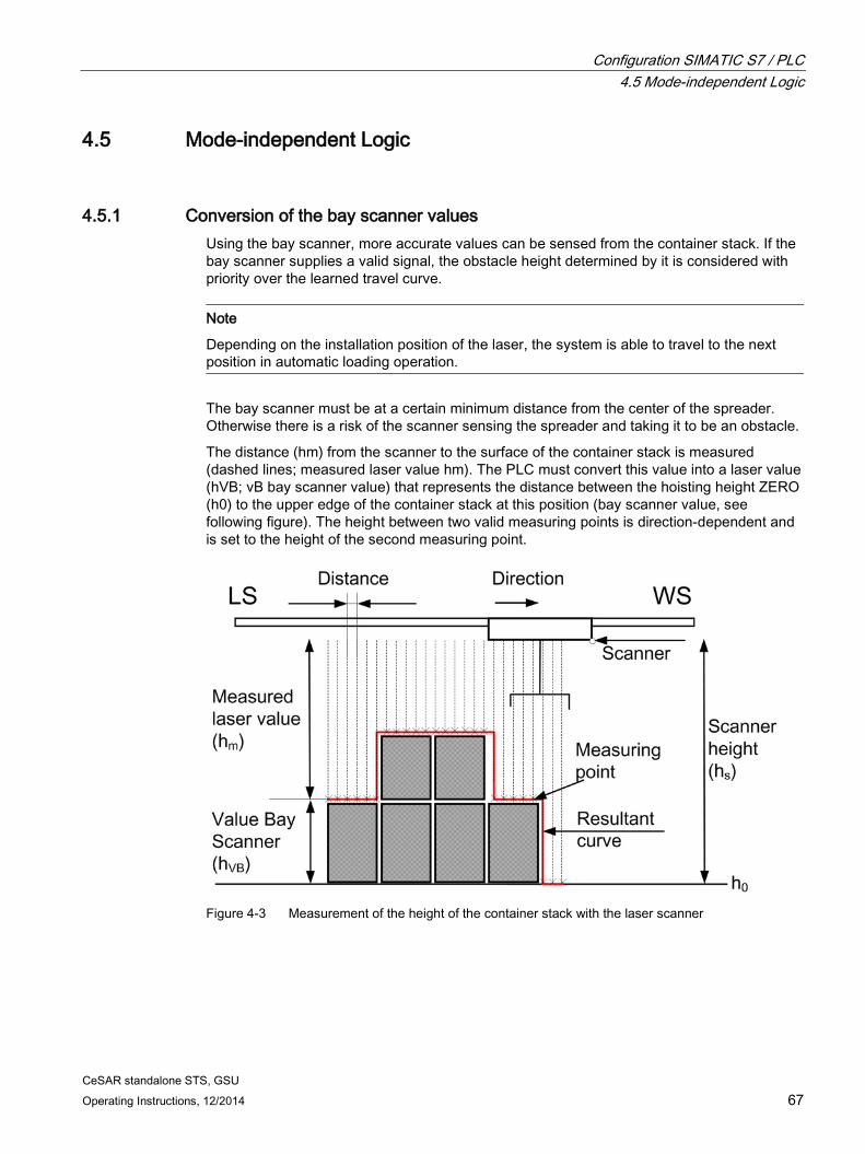
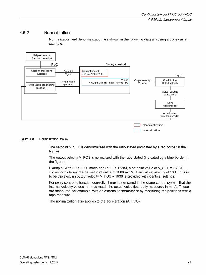
4.5 Mode-independent Logic ....................................................................................................... 67 4.5.1 Conversion of the bay scanner values ................................................................................... 67 4.5.2 Normalization ......................................................................................................................... 71 4.5.3 Generating the "TRAVEL" control bit ..................................................................................... 72 4.5.4 Drive activation and brake control.......................................................................................... 73 4.5.5 Controlled stop ....................................................................................................................... 74
4.6 Acceleration and deceleration behavior ................................................................................. 74
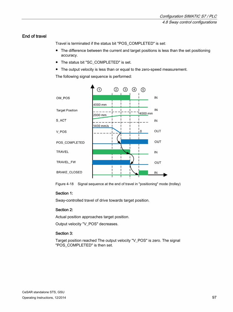
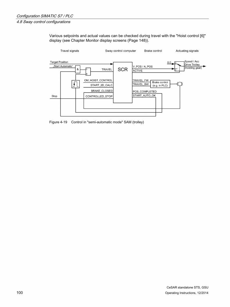
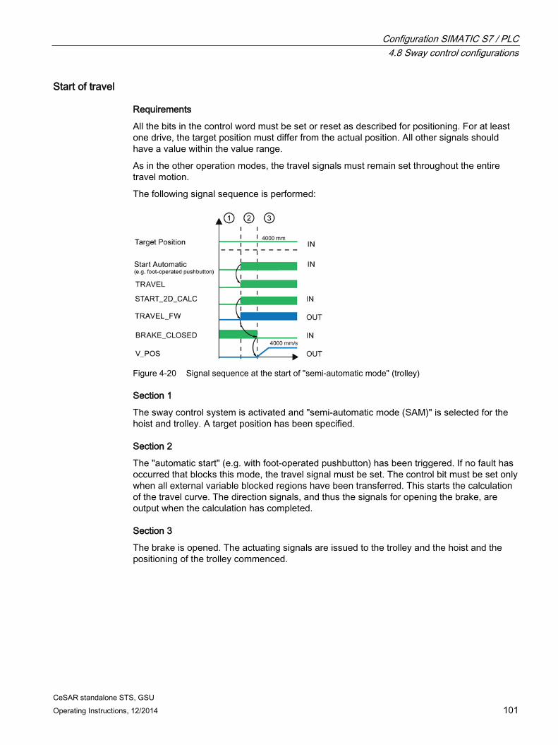
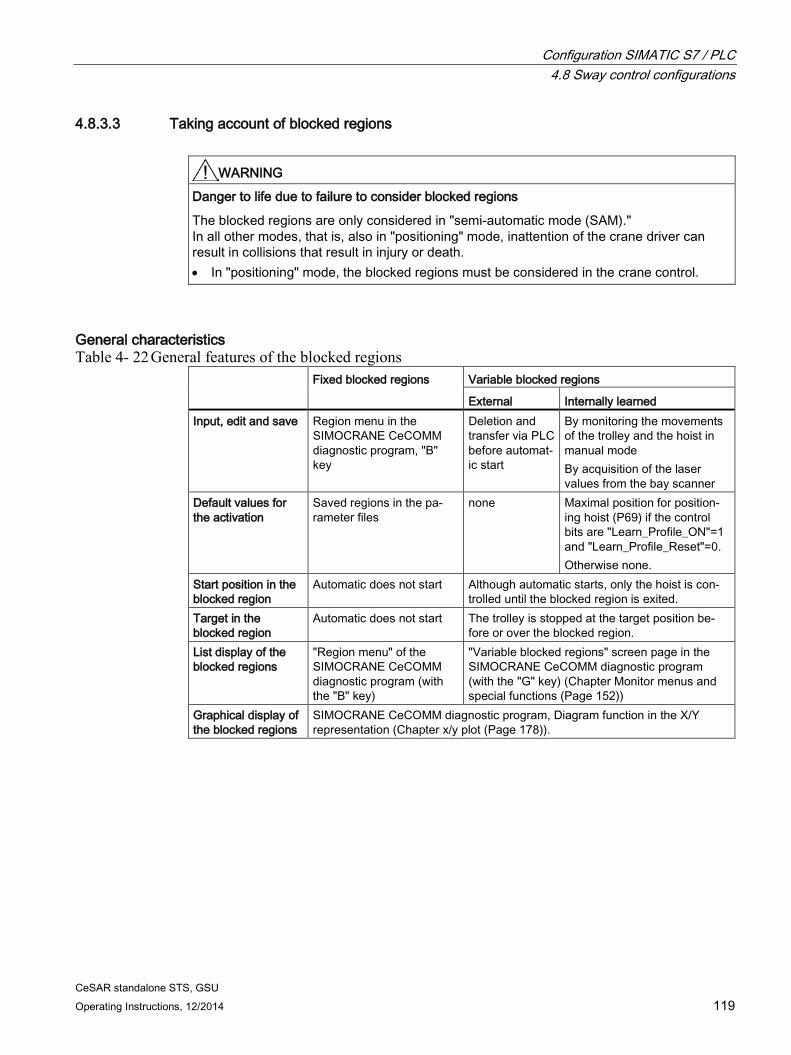
4.8 Sway control configurations ................................................................................................... 92 4.8.1 General .................................................................................................................................. 92 4.8.2 Sway control controlling ......................................................................................................... 92 4.8.2.1 Control in "manual mode" (MAN) ........................................................................................... 92 4.8.2.2 Control in "positioning" (POS) mode ...................................................................................... 96 4.8.2.3 Control in "semi-automatic mode" (SAM) .............................................................................. 99 4.8.2.4 Control in mixed use of POS and MAN ............................................................................... 106 4.8.3 Sway control with extended functions .................................................................................. 110 4.8.3.1 Definitions ............................................................................................................................ 110 4.8.3.2 Further functions in "semi-automatic mode" (SAM) ............................................................. 114 4.8.3.3 Taking account of blocked regions ...................................................................................... 119 4.8.3.4 Double spreader in coupled mode ....................................................................................... 124
4.9 TLS Control .......................................................................................................................... 125 4.9.1 TLS control with camera measuring system (STS only) ...................................................... 125 4.9.1.1 General information ............................................................................................................. 125 4.9.1.2 Mechanical requirements for TLS with a hydraulic system ................................................. 127 4.9.1.3 Mechanical requirements for TLS with a hydraulic system and electric axis....................... 128 4.9.1.4 TLS modes and functions .................................................................................................... 131 4.9.2 Control of a cylinder movement ........................................................................................... 134 4.9.3 Control of a movement of the electric axis ........................................................................... 135 4.9.4 Control of the modes and the skew damping for the hydraulic system ............................... 136 4.9.5 Control of travel and skew damping with the electric axis ................................................... 137
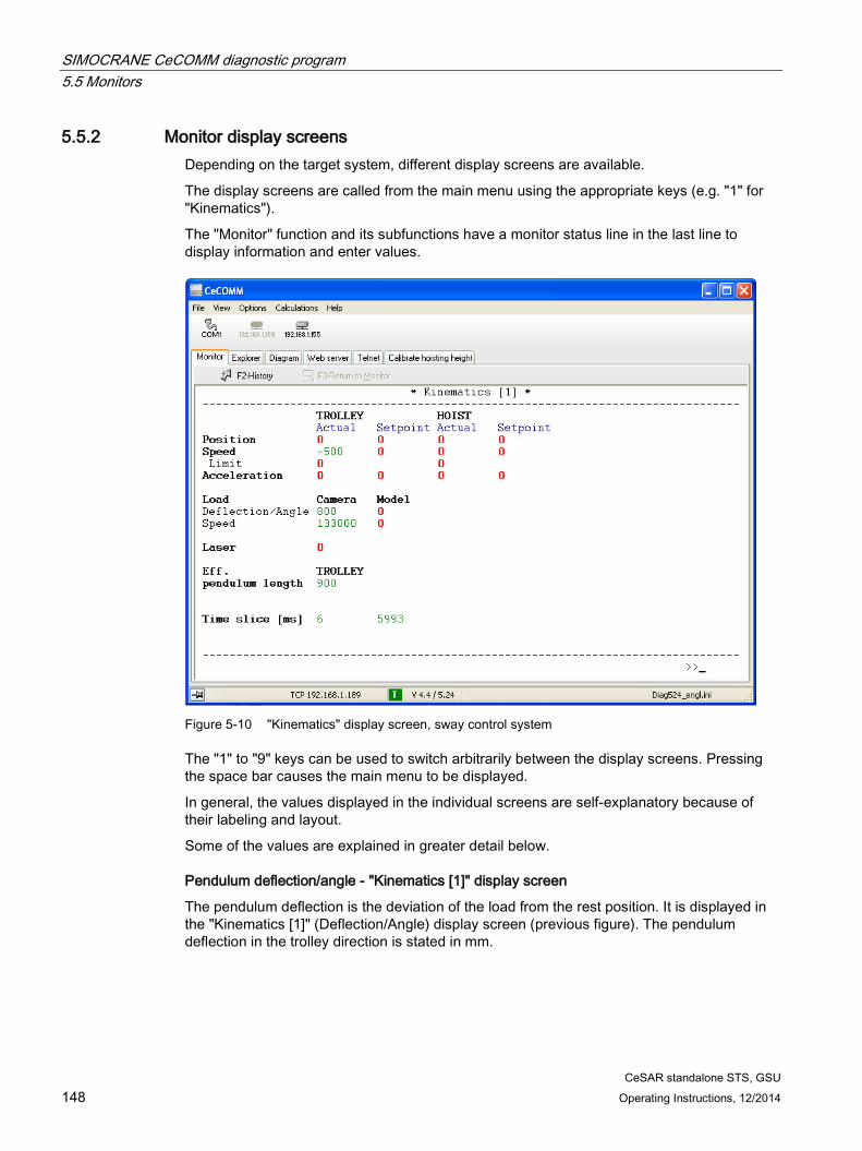
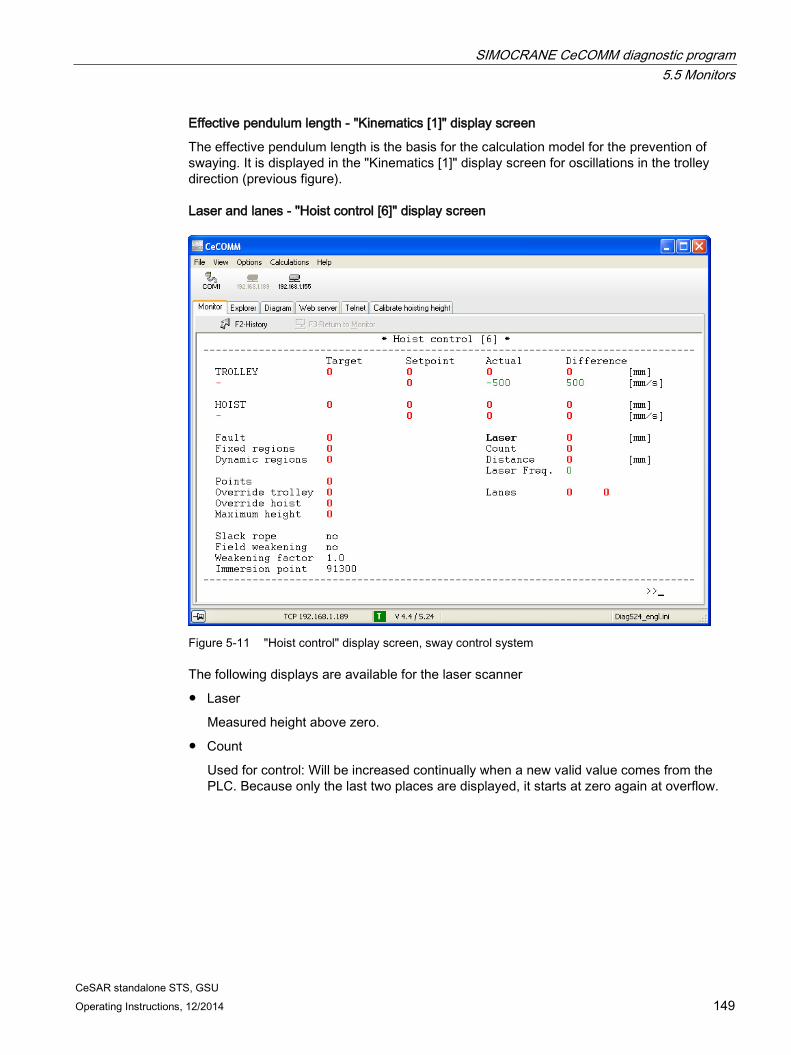
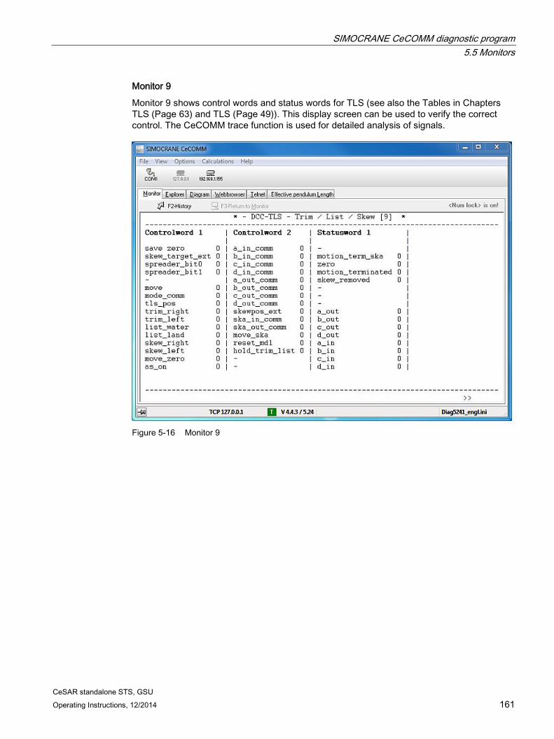
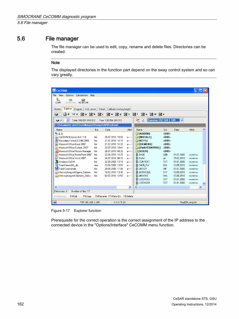
5 SIMOCRANE CeCOMM diagnostic program ........................................................................................ 139
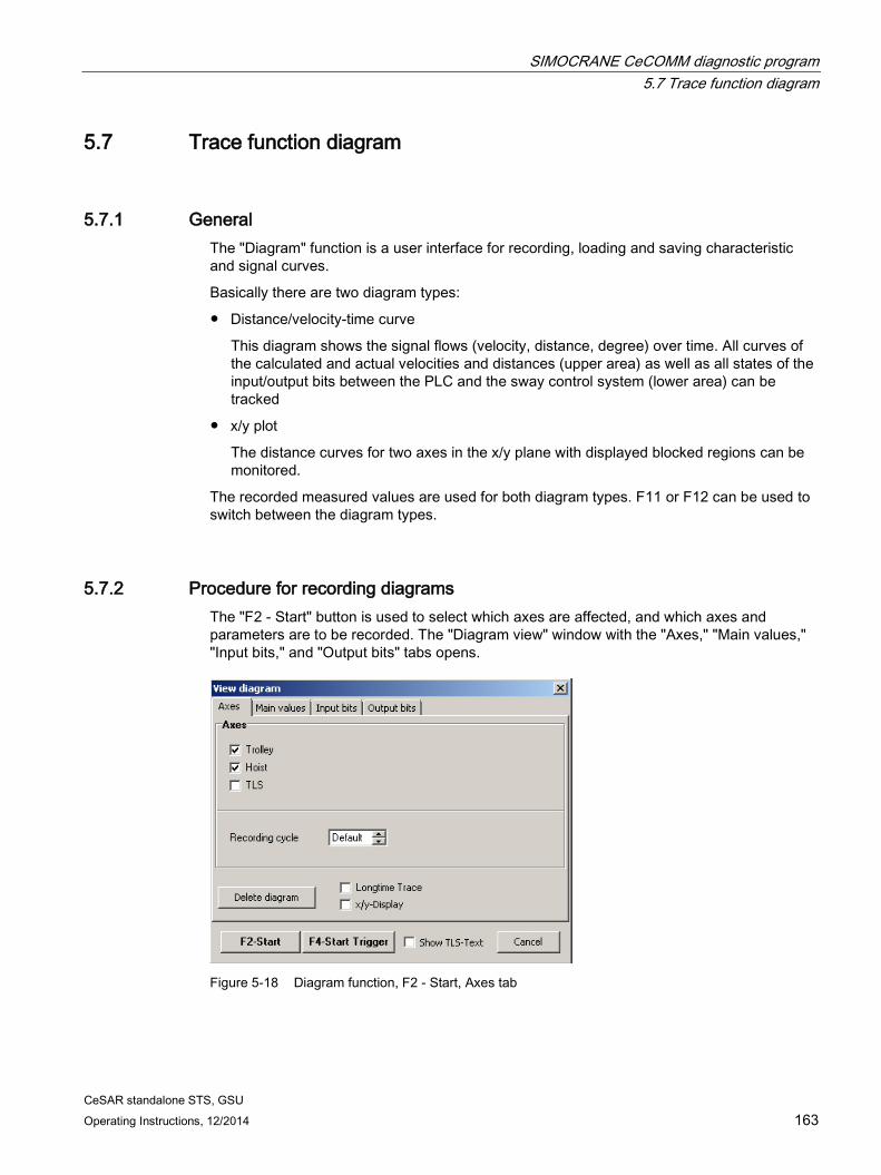
5.7 Trace function diagram ......................................................................................................... 163 5.7.1 General ................................................................................................................................. 163 5.7.2 Procedure for recording diagrams ........................................................................................ 163 5.7.3 Elements and functionality of the diagram user interface ..................................................... 168 5.7.4 x/y plot ................................................................................................................................... 178 5.7.5 TLS-Trace ............................................................................................................................. 180
5.8 Web browser ......................................................................................................................... 182
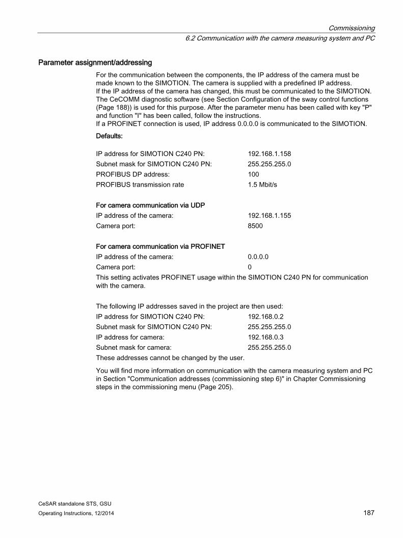
6.2 Communication with the camera measuring system and PC ............................................... 186
6.3 Configuration of the sway control functions .......................................................................... 188 6.3.1 Overview ............................................................................................................................... 188 6.3.2 Calling up the parameter menu ............................................................................................ 189 6.3.3 Activating a parameter set .................................................................................................... 189 6.3.4 Editing a parameter set ......................................................................................................... 190 6.3.5 Changing a parameter .......................................................................................................... 190 6.3.6 Copying a parameter set ...................................................................................................... 191 6.3.7 Loading the saved parameter sets ....................................................................................... 191 6.3.8 Saving all sets of parameters ............................................................................................... 191 6.3.9 Switching over parameter sets ............................................................................................. 192 6.3.10 Setting default values............................................................................................................ 192 6.3.11 More functions ...................................................................................................................... 192
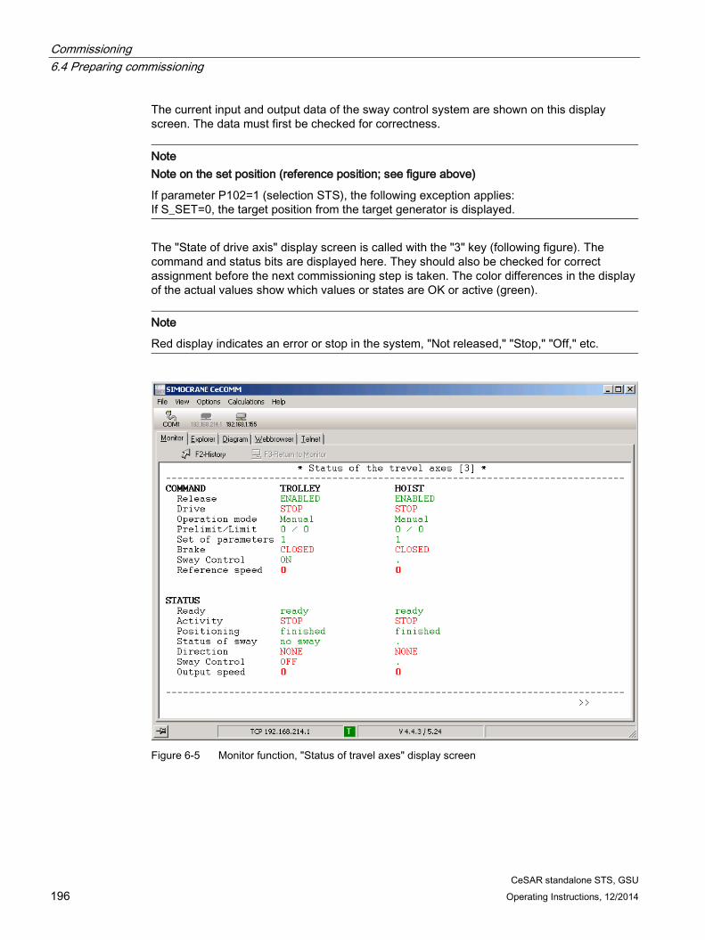
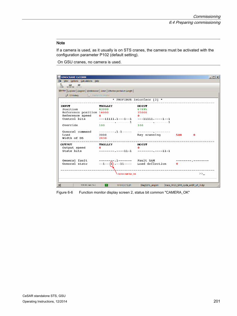
6.4 Preparing commissioning ..................................................................................................... 193 6.4.1 Load measurement ............................................................................................................... 193 6.4.2 Position sensing .................................................................................................................... 193 6.4.3 Preparing the PLC program .................................................................................................. 193 6.4.4 Setting the access code ........................................................................................................ 194 6.4.5 Setting the language ............................................................................................................. 195 6.4.6 Checking of the communication between PLC and SIMOTION ........................................... 195 6.4.7 Preparing the SIMOCRANE CenSOR camera measuring system ...................................... 197 6.4.8 Preparing the converter ........................................................................................................ 197 6.4.8.1 Converter parameter sets ..................................................................................................... 197 6.4.8.2 Acceleration and deceleration ramps ................................................................................... 198 6.4.8.3 Initial and final rounding ........................................................................................................ 198 6.4.8.4 Minimum converter frequency .............................................................................................. 198 6.4.8.5 Speed controller of the converter .......................................................................................... 199 6.4.8.6 Velocity limits ........................................................................................................................ 199 6.4.8.7 Check of the control response .............................................................................................. 200 6.4.9 Checking the communication with the camera measuring system ....................................... 200
Table of contents
CeSAR standalone STS, GSU 8 Operating Instructions, 12/2014
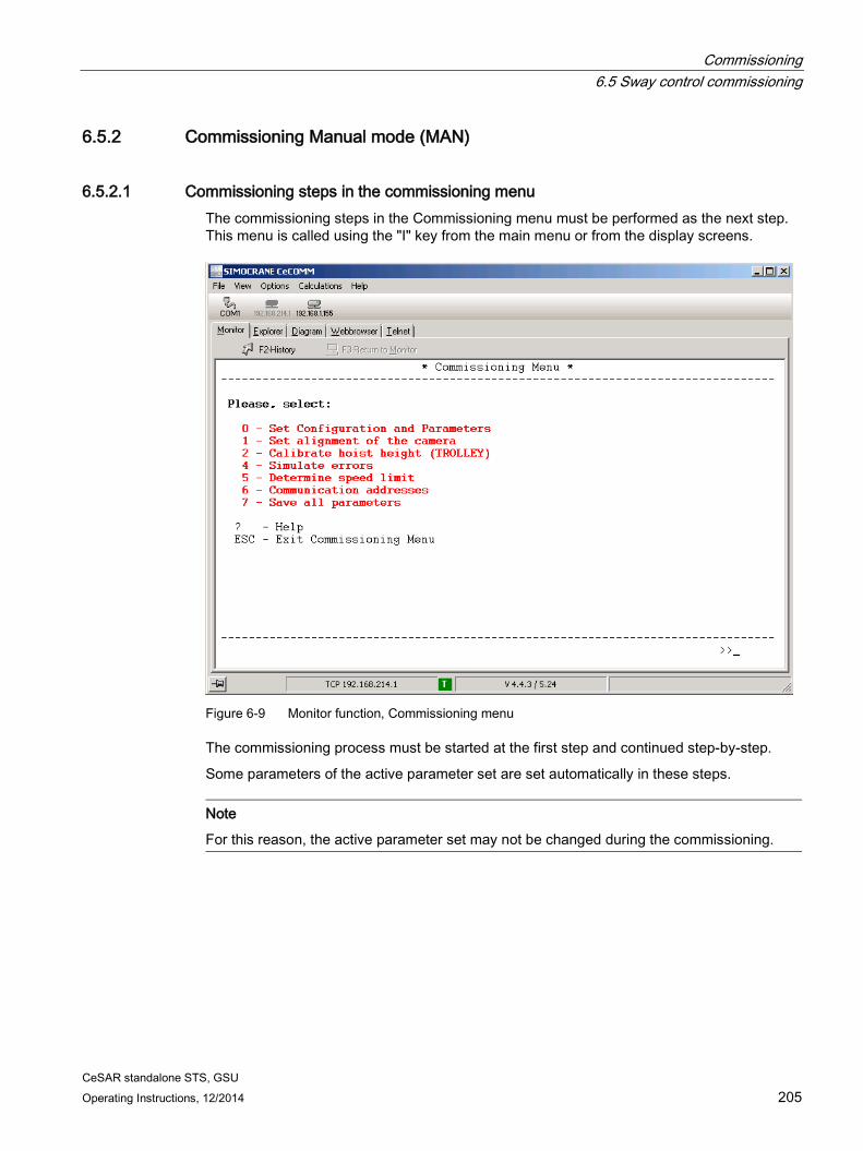
6.5 Sway control commissioning ................................................................................................ 202 6.5.1 Method of operation of sway control .................................................................................... 202 6.5.2 Commissioning Manual mode (MAN) .................................................................................. 205 6.5.2.1 Commissioning steps in the commissioning menu .............................................................. 205 6.5.2.2 Checking and fine-tuning the sway control system.............................................................. 212 6.5.3 Commissioning positioning mode (POS) ............................................................................. 215 6.5.3.1 Changing the coordinate system ......................................................................................... 215 6.5.3.2 Position controller setting ..................................................................................................... 216 6.5.3.3 On-the-fly unloading ............................................................................................................. 217 6.5.3.4 Other settings ....................................................................................................................... 218 6.5.4 Commissioning semi-automatic (SAM) mode ...................................................................... 219
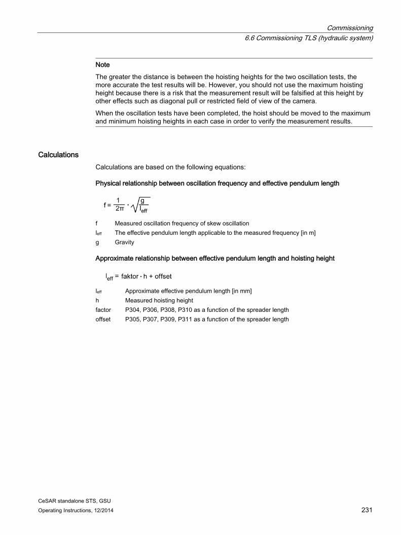
6.6 Commissioning TLS (hydraulic system) .............................................................................. 224 6.6.1 System requirements ........................................................................................................... 224 6.6.2 Activating the TLS functions ................................................................................................ 225 6.6.3 Parameterization of the actual positions .............................................................................. 225 6.6.4 Parameterizing "cylinder inching" mode .............................................................................. 226 6.6.5 Parameterization of the central positions of the cylinders ................................................... 228 6.6.6 TLS inching and go to zero positions ................................................................................... 229 6.6.7 Kinematic transformation cylinder positions, angle of rotation ............................................ 229 6.6.8 Calculation of the effective pendulum length for the skew oscillation.................................. 230 6.6.9 Monitoring the camera measuring system ........................................................................... 233 6.6.10 Parameterization of observer ............................................................................................... 234 6.6.11 Activates the "skew damping" function ................................................................................ 234 6.6.12 Optional adaptations ............................................................................................................ 234
6.7 Commissioning TLS (hydraulic system with electric axis) ................................................... 236 6.7.1 System requirements ........................................................................................................... 236 6.7.2 Commissioning cylinders ..................................................................................................... 236 6.7.3 Evaluation of the current position of the skew drive spindle ................................................ 237 6.7.4 Position controller setting (P328) ......................................................................................... 238 6.7.5 Setting the limit for set position P324 .................................................................................. 238 6.7.6 Kinematic transformation position electric axis, angle of rotation ........................................ 239 6.7.7 Parameterization of skew damping ...................................................................................... 240
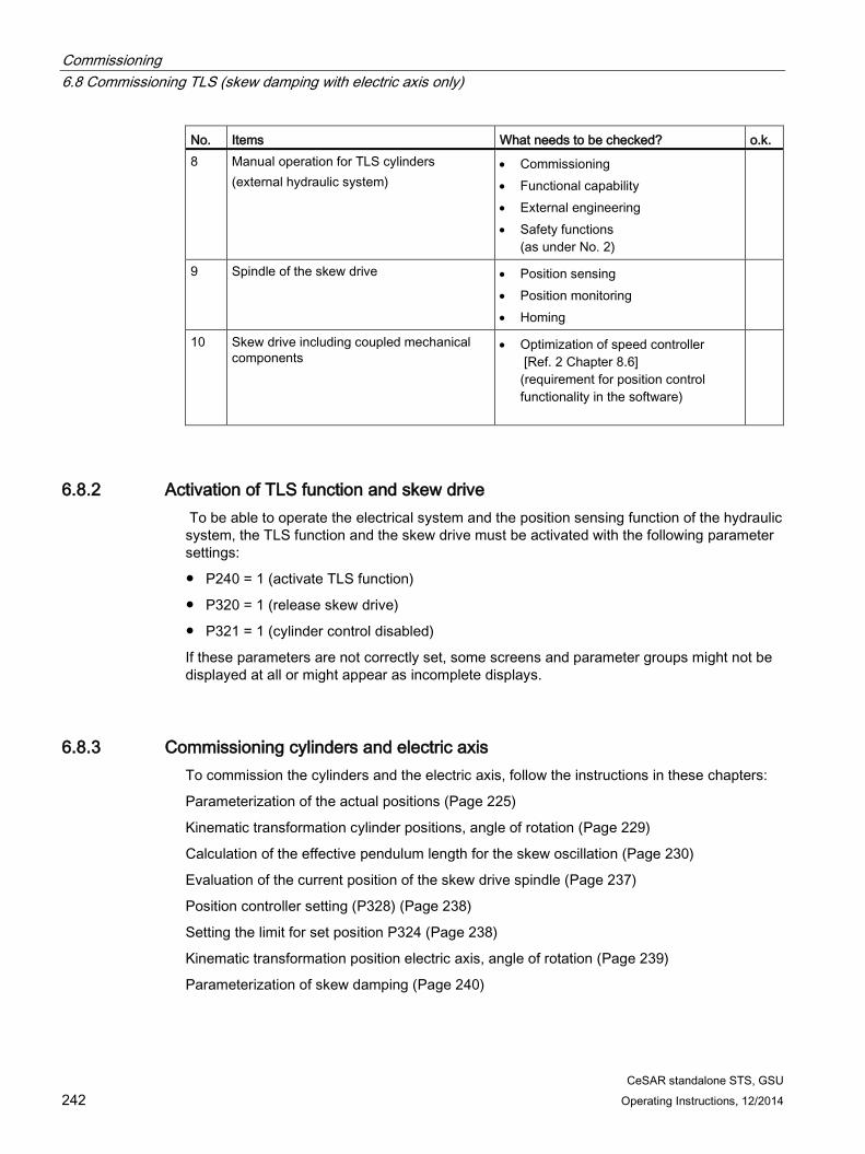
6.8 Commissioning TLS (skew damping with electric axis only) ............................................... 241 6.8.1 System requirements ........................................................................................................... 241 6.8.2 Activation of TLS function and skew drive ........................................................................... 242 6.8.3 Commissioning cylinders and electric axis .......................................................................... 242
7 Alarm, error, and system messages ..................................................................................................... 243
7.1 General information ............................................................................................................. 243
7.2 Following error monitoring ................................................................................................... 243
CeSAR standalone STS, GSU Operating Instructions, 12/2014 9
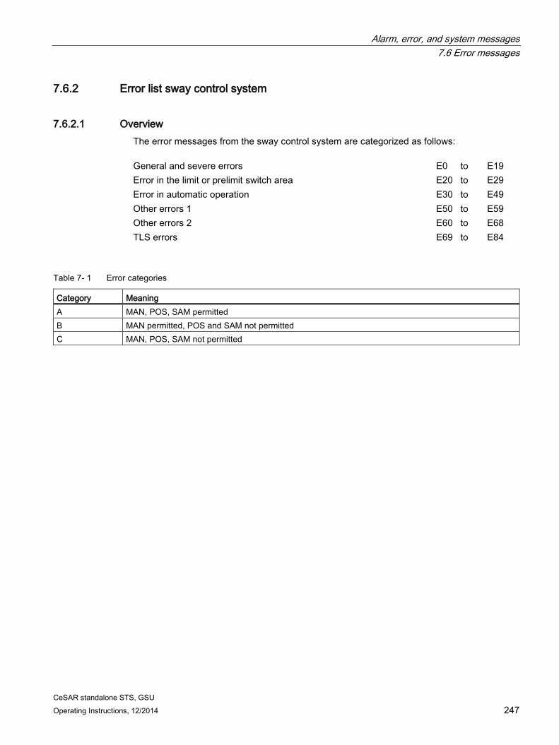
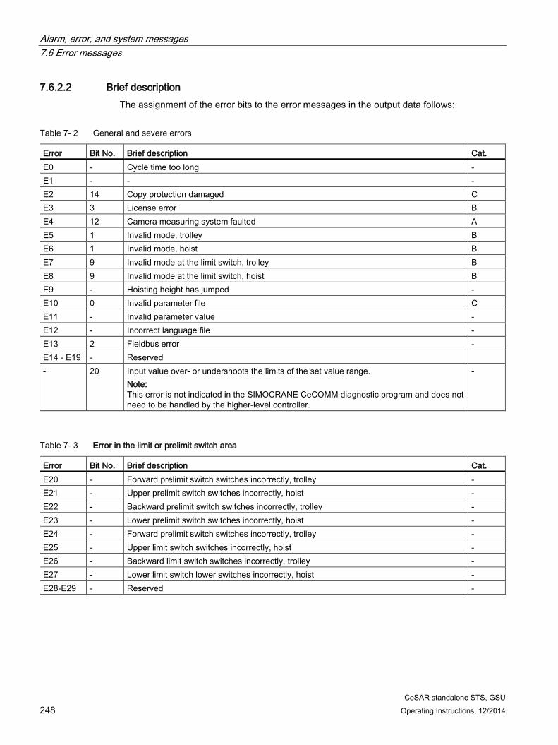
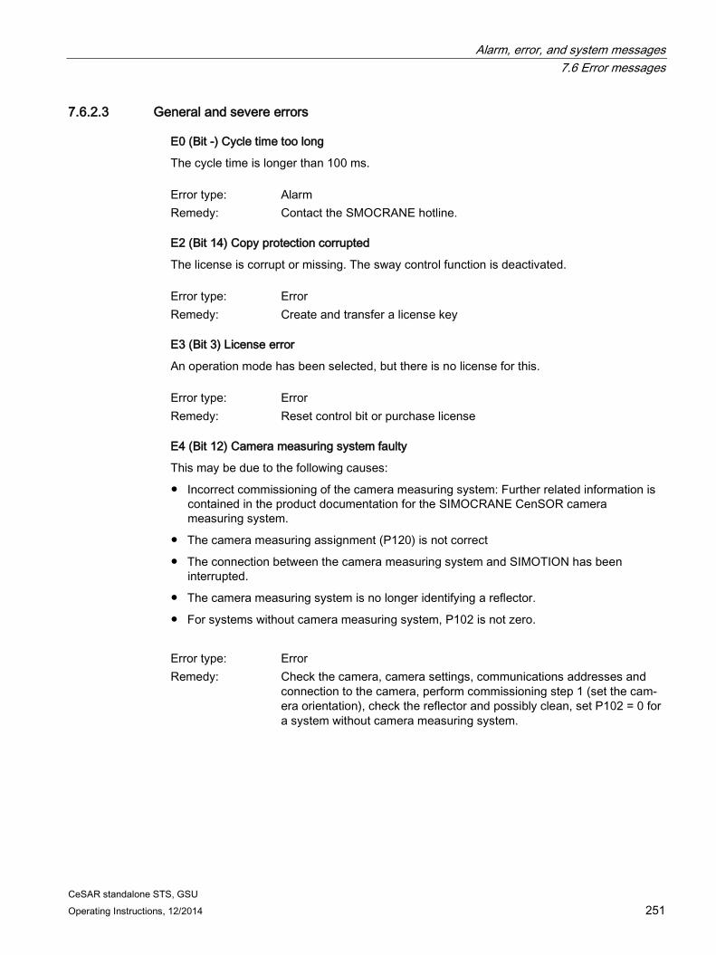
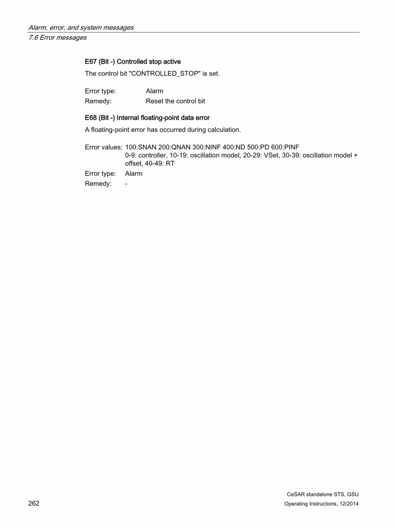
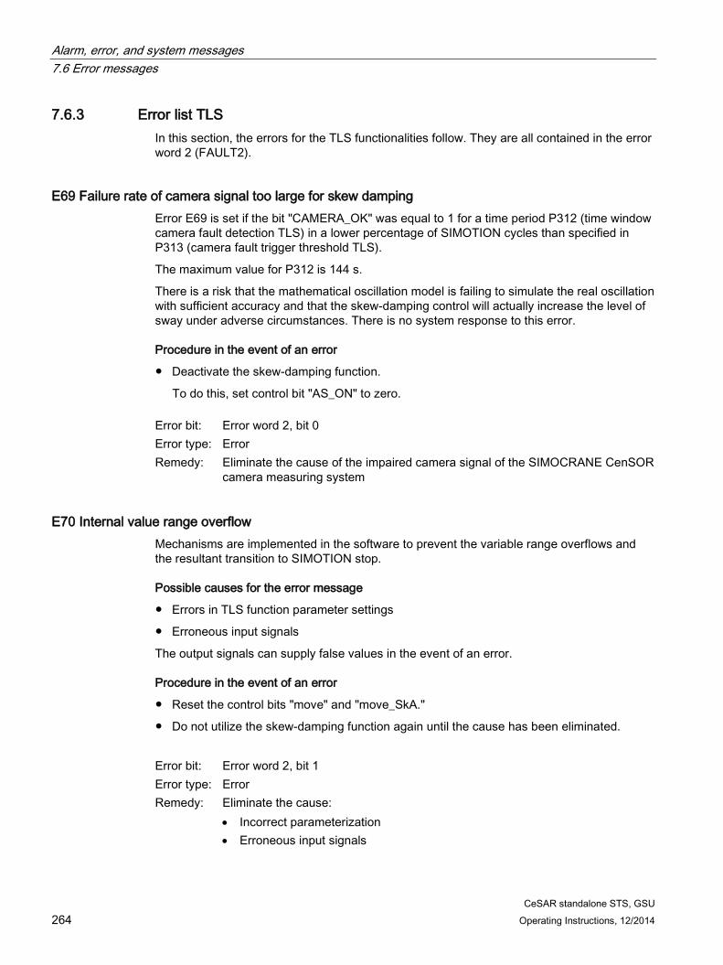
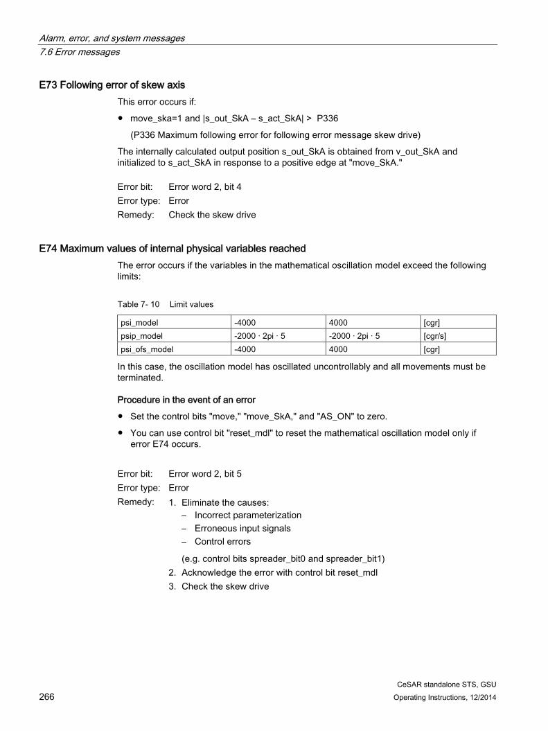
7.6 Error messages ..................................................................................................................... 246 7.6.1 General information .............................................................................................................. 246 7.6.2 Error list sway control system ............................................................................................... 247 7.6.2.1 Overview ............................................................................................................................... 247 7.6.2.2 Brief description .................................................................................................................... 248 7.6.2.3 General and severe errors .................................................................................................... 251 7.6.2.4 Error in the limit or prelimit switch area................................................................................. 254 7.6.2.5 Error in "semi-automatic mode" ............................................................................................ 256 7.6.2.6 Other errors 1 ........................................................................................................................ 259 7.6.2.7 Other errors 2 ........................................................................................................................ 261 7.6.2.8 SIMOCRANE CeCOMM diagnostic program ....................................................................... 263 7.6.2.9 Troubleshooting/FAQs .......................................................................................................... 263 7.6.3 Error list TLS ......................................................................................................................... 264
A Appendix............................................................................................................................................. 317
A.1 Service and maintenance ..................................................................................................... 317
A.2 Spare parts ........................................................................................................................... 318
CeSAR standalone STS, GSU 10 Operating Instructions, 12/2014
CeSAR standalone STS, GSU Operating Instructions, 12/2014 11
Fundamental safety instructions 1 1.1 General safety instructions relating to hardware
DANGER
Danger to life due to live parts and other energy sources
Death or serious injury can result when live parts are touched. • Only work on electrical devices when you are qualified for this job. • Always observe the country-specific safety rules.
Generally, six steps apply when establishing safety: 1. Prepare for shutdown and notify all those who will be affected by the procedure. 2. Disconnect the machine from the supply.
– Switch the machine off. – Wait until the discharge time specified on the warning labels has elapsed. – Check that it really is in a no-voltage condition, from phase conductor to phase
conductor and phase conductor to protective conductor. – Check whether the existing auxiliary supply circuits are de-energized. – Ensure that the motors cannot move.
3. Identify all other hazardous energy sources, e.g. compressed air, hydraulic or water. 4. Isolate or neutralize all hazardous energy sources by closing switches, grounding or
short-circuiting, or closing valves, for example. 5. Secure the energy sources against switching on again. 6. Ensure that the correct machine is completely interlocked.
After you have completed the work, restore the operational readiness in the inverse sequence.
WARNING
Danger to life from hazardous voltage when connecting an unsuitable power supply
Touching live components can result in death or severe injury. • Only use power supplies that provide SELV (Safety Extra Low Voltage) or PELV-
(Protective Extra Low Voltage) output voltages for all connections and terminals of the electronics modules.
Fundamental safety instructions 1.2 General safety instructions relating to software
CeSAR standalone STS, GSU 12 Operating Instructions, 12/2014
WARNING
Danger to life through unexpected movement of machines when using mobile wireless devices or mobile phones
Using mobile radios or mobile phones with a transmit power > 1 W closer than approx. 2 m to the components may cause the devices to malfunction. This in turn influences the functional safety of machines, therefore putting people at risk or causing material damage. • Switch the wireless devices or mobile phones off in the immediate vicinity of the
components.
1.2 General safety instructions relating to software
WARNING
Risk of death if the safety instructions and remaining risks are not carefully observed
If the safety instructions and residual risks are not observed in the associated hardware documentation, accidents involving severe injuries or death can occur. • Observe the safety instructions provided in the hardware documentation. • Take into account residual risks when assessing risks.
WARNING
Danger to life or malfunctions of the machine as a result of incorrect or changed parameter assignment
Machines can malfunction as a result of incorrect or changed parameter assignment, which in turn can lead to injuries or death. • Protect the parameterization (parameter assignments) against unauthorized access. • Respond to possible malfunctions by applying suitable measures (e.g. Emergency stop
or Emergency switching off).
WARNING
Danger to life posed by uncontrolled changeover between operating states
Uncontrolled changeover between operating states can cause machines to malfunction, which in turn can lead to injuries or death. • Assess the effects of changeover between operating states in the risk analysis. • Provide appropriate safety measures, e.g. Emergency switching off.
Fundamental safety instructions 1.3 Industrial security
CeSAR standalone STS, GSU Operating Instructions, 12/2014 13
1.3 Industrial security
Note Industrial security
Siemens provides products and solutions with industrial security functions that support the secure operation of plants, solutions, machines, equipment and/or networks. They are important components in a holistic industrial security concept. With this in mind, Siemens’ products and solutions undergo continuous development. Siemens recommends strongly that you regularly check for product updates.
For the secure operation of Siemens products and solutions, it is necessary to take suitable preventive action (e.g. cell protection concept) and integrate each component into a holistic, state-of-the-art industrial security concept. Third-party products that may be in use should also be considered. For more information about industrial security, visit Hotspot-Text (http://www.siemens.com/industrialsecurity).
To stay informed about product updates as they occur, sign up for a product-specific newsletter. For more information, visit Hotspot-Text (http://support.automation.siemens.com).
WARNING
Danger as a result of unsafe operating states resulting from software manipulation
Software manipulation (e.g. by viruses, Trojan horses, malware, worms) can cause unsafe operating states to develop in your installation which can result in death, severe injuries and/or material damage. • Keep the software up to date.
You will find relevant information and newsletters at this address (http://support.automation.siemens.com).
• Incorporate the automation and drive components into a holistic, state-of-the-art industrial security concept for the installation or machine. You will find further information at this address (http://www.siemens.com/industrialsecurity).
• Make sure that you include all installed products into the holistic industrial security concept.
Fundamental safety instructions 1.3 Industrial security
CeSAR standalone STS, GSU 14 Operating Instructions, 12/2014
CeSAR standalone STS, GSU Operating Instructions, 12/2014 15
System description 2 2.1 Introduction
Every movement of the trolley of a crane causes the load to sway. This makes positioning more difficult, and it takes correspondingly longer. The main purpose of the sway control system is to eliminate the sway motion so that automatic positioning can be performed and manual movement by the crane driver is made easier. This can relieve the crane operator and increase the handling capacity. Without an electronic sway control system, implementing crane controls in automatic operation is hardly conceivable.
To meet this challenge, Siemens Cranes provides not only an expandable modular and integrated sway control system [Ref. 3] based on SIMOCRANE Basic Technology but also a standalone sway control system.
The "SIMOCRANE CeSAR standalone STS, GSU" standalone sway control system is based on the SIMOTION C240 PN platform. It can be used independently of Siemens control systems and drives. Communication is performed via PROFIBUS-DP. SIMOCRANE CeSAR standalone STS, GSU is suitable for new crane systems or as a modernization solution for existing crane systems or to enhance crane performance by upgrading.
The sway control system performs the following tasks:
1. "Manual mode" (MAN), separately for the trolley and for the hoist
2. "Positioning" (POS) mode, separate for the trolley and for the hoist (semi-automatic movement without considering obstacles)
3. "Semi-automatic mode" (SAM) for combined motion of the trolley and hoist (semi-automatic movement considering obstacles). Detection of obstacles and the resulting formation of blocked regions can be achieved in different ways and is described in detail in the document. A bay scanner can also be used to detect the container stack. A two-dimensional trajectory is generated for the hoist and trolley, with consideration of all obstacles.
4. "Sway neutralization to load position" (SNL) and "Sway neutralization to drive position" (SND) modes.
5. TLS control with STS configuration. In this way, control of the TLS cylinders, positioning, and skew damping can be performed. Skew damping can also be achieved with an additional electric drive.
6. A target generator is available for STS configuration. With it, it is possible to generate target positions for POS and SAM modes in many different ways. Alternatively, the targets can be defined via the crane control system.
7. The target generator is not available for GSU configuration. The target positions can only be defined via the crane control system.
System description 2.2 System overview
CeSAR standalone STS, GSU 16 Operating Instructions, 12/2014
2.2 System overview
2.2.1 System structure The sway control system is designed for crane control systems with SIMOTION C240 PN:
● Use of a crane control system (PLC) with a PROFIBUS interface
● SIMOTION C240 PN as the hardware platform
● Closed-loop controlled drives
● Position encoder for the hoist
● Position encoder for the trolley using POS, SAM, SND, and SNL modes.
The sway control system is offered as a "black box." That means the hardware (SIMOTION C) and the executable software on a memory card are supplied together in one package.
Depending on requirements, additional hardware may be required (e.g. camera measuring system, reflector, TLS control system, hub, bay scanner, HMI, etc.) or the relevant requirements may have to be created.
The following diagram shows an example of communication between the individual components.
Figure 2-1 Layout diagram of the components
System description 2.2 System overview
CeSAR standalone STS, GSU Operating Instructions, 12/2014 17
The necessary process information is supplied to the sway control system via:
● the crane control system,
● the SIMOCRANE CenSOR camera measuring system (optional).
2.2.2 Versions The sway control system can be operated with or without a camera measuring system.
Version without camera measuring system for ship unloader (GSU) This version is designed for use on cranes that cannot be equipped with a camera measuring system for design-related reasons or which operate in harsh environmental conditions such as extremely dusty atmospheres or at very high temperatures.
The sway control system ascertains the oscillation states using a mathematical pendulum model. The version without camera measuring system is capable of eliminating most oscillations that are caused by crane motion. However, it is not capable of suppressing sway caused by external forces such as diagonal pull or wind.
This is the preferred version for ship unloaders (GSU). The camera measuring system must be deactivated with the configuration parameter (P102 = 0). All of the functions, parameters, and fault messages described in this documentation, which refer to the camera measuring system, are then suppressed and deactivated.
System description 2.2 System overview
CeSAR standalone STS, GSU 18 Operating Instructions, 12/2014
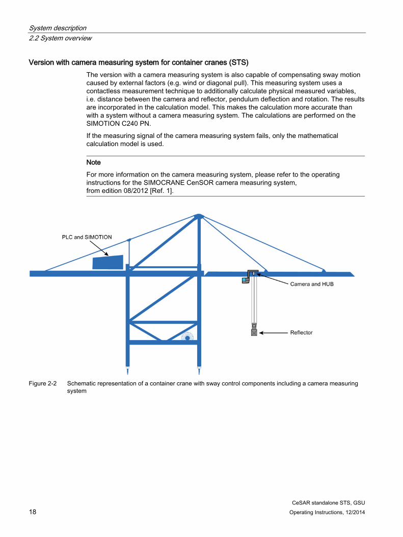
Version with camera measuring system for container cranes (STS) The version with a camera measuring system is also capable of compensating sway motion caused by external factors (e.g. wind or diagonal pull). This measuring system uses a contactless measurement technique to additionally calculate physical measured variables, i.e. distance between the camera and reflector, pendulum deflection and rotation. The results are incorporated in the calculation model. This makes the calculation more accurate than with a system without a camera measuring system. The calculations are performed on the SIMOTION C240 PN.
If the measuring signal of the camera measuring system fails, only the mathematical calculation model is used.
Note
For more information on the camera measuring system, please refer to the operating instructions for the SIMOCRANE CenSOR camera measuring system, from edition 08/2012 [Ref. 1].
Figure 2-2 Schematic representation of a container crane with sway control components including a camera measuring
system
System description 2.2 System overview
CeSAR standalone STS, GSU Operating Instructions, 12/2014 19
Version with TLS functions for container cranes (STS) On STS cranes the spreader can be rotated in all directions (x axis, y axis, z axis) independently of the hoist and trolley motions.
The software described in this document provides a TLS function in the SIMOTION control system. The TLS movements are realized by two different systems.
Hydraulic system with four hydraulic cylinders
Functionalities:
● Four operation modes:
– Cylinder inching
– Go to zero positions (including the save zero positions function)
– TLS inching (trim/list/skew)
– TLS positioning
● Skew-damping function
Electrical system with an additional skew drive
Functionalities:
● Skew-damping function
● TLS inching (skew drive)
Note
Skew damping is not possible without a camera measuring system.
Skew damping is performed either via the cylinders or, if there is one, via an electric skew drive. The remaining TLS movements are still performed via the cylinders.
System description 2.2 System overview
CeSAR standalone STS, GSU 20 Operating Instructions, 12/2014
2.2.3 Functional scope An overview of the modes and the dependencies on other systems and the associated functions is shown in the following table.
separate for the trolley and for the hoist Basic license
Positioning (POS) Positioning without considering obsta-cles, separately for the trolley and hoist.
Basic license
Sway neutralization to load position (SNL)
Sway neutralization from standstill with the load position as the target position for the trolley
Basic license
Sway neutralization to drive position (SND)
Sway neutralization from standstill with the drive position as the target position for the trolley
Basic license
"TLS basic" modes • Cylinder inching • Go to zero positions • TLS inching (trim/list/skew)
Basic license
Semi-automatic mode (SAM) • Automatic positioning with external-ly defined targets
• Automatic target definition in con-junction with a target generator
• Taking into account obstacles • Calculation of the 2-dimensional
trajectory for hoist and trolley
Advanced license
"TLS advanced" modes • Cylinder inching • Go to zero positions • TLS inching • TLS inching (skew drive) • TLS positioning • Skew damping
Advanced license
System description 2.3 Scope of supply
CeSAR standalone STS, GSU Operating Instructions, 12/2014 21
2.3 Scope of supply Depending on the task to be performed and the environmental conditions, the sway control system can be implemented with or without the SIMOCRANE CenSOR camera measuring system. The hardware and software required for the camera measuring system must be ordered separately. For information see the operating instructions for the SIMOCRANE CenSOR camera measuring system [Ref. 1].
SIMOCRANE CeSAR standalone STS, GSU comprises:
● SIMOTION C240 PN
● Mounting rail
● MMC memory card for SIMOTION C240 PN configured for sway control
The MMC memory card was assigned with all of the required licenses.
The MMC memory card contains:
– The SIMOTION Kernel (basic system)
– Technology packages and user data (programs, configuration data, parameter settings)
– Runtime licenses
● Product DVD
The product DVD contains:
– Installation instructions
– Readme file
□ German
□ English
– Readme_OSS
□ German
□ English
– Software
□ Setup program for the SIMOCRANE CeCOMM diagnostic program (setup file)
□ Card image for the MMC memory card
□ Application example
– Documentation Operating Instructions SIMOCRANE CeSAR standalone STS, GSU
□ German
□ English
System description 2.3 Scope of supply
CeSAR standalone STS, GSU 22 Operating Instructions, 12/2014
– Documentation SIMOTION C Operating Instructions
□ German
□ English
● Certificates for software licenses
Depending on the required function scope, one of two RT licenses can be chosen.
License Article No. Functionality SIMOCRANE CeSAR standalone Basic Control
* The relevant definitions can be found in the Table 2-1 Overview of operation modes (Page 20).
Because the memory card (MMC card) is included in the scope of supply, the relevant license is provided on it as the license key.
CeSAR standalone STS, GSU Operating Instructions, 12/2014 23
Hardware installation 3 3.1 Introduction
The SIMOTION C240 PN is the main component of the sway control system SIMOCRANE CeSAR standalone STS, GUS.
The following section provides an introduction to installing the SIMOTION C240 PN. Please refer to the Operating Instructions [Ref. 4] supplied within the package for further information and details.
The executable software is stored on the memory card (MMC) supplied and on the product DVD.
Note
The SIMOTION C240 PN must only be used for the standalone sway control system.
SIMOTION C240 PN view
Figure 3-1 SIMOTION C240 PN
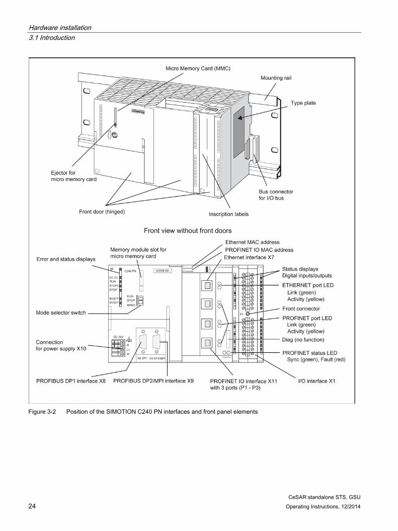
The following image shows the SIMOTION C240 PN module with its interfaces and front panel elements (error and status displays).
Hardware installation 3.1 Introduction
CeSAR standalone STS, GSU 24 Operating Instructions, 12/2014
Figure 3-2 Position of the SIMOTION C240 PN interfaces and front panel elements
Hardware installation 3.2 Mechanical installation
CeSAR standalone STS, GSU Operating Instructions, 12/2014 25
3.2 Mechanical installation In this section we will explain how to prepare the SIMOTION C240 PN components for installation and how to install them.
Installation instructions
Installing the mounting rail
1. Fit the mounting rail in a position that will allow enough room for the modules to be installed and for the heat to dissipate (a minimum of 40 mm above and below the mounting rail).
2. Screw the mounting rail onto the surface where it is to be affixed (screw size: M6). Is the support a grounded metal plate or a grounded equipment mounting plate? If so: ensure that there is a low-resistance connection between the mounting rail and the support. Use suitable electro-lubricant or contact washers with painted and anodized metals, for example. If not: no special action required.
3. Connect the mounting rail with the protective conductor. An M6 screw is provided on the rail for this purpose. Minimum cross-section from the cable to the protective conductor: 10 mm2.
Hang the SIMOTION C240 PN on the mounting rail
1. Hang the SIMOTION C240 PN onto the top of the rail and swing it down.
2. Screw down the module applying a torque of 0.8 to 1.1 Nm.
Insert the micro memory card (MMC)
1. Switch off the power supply module.
2. Insert the micro memory card into the module slot of the SIMOTION C240 PN by applying slight pressure until it snaps into place. Make sure the beveled edge of the micro memory card faces the ejector.
3. Switch the power supply module back on.
Hardware installation 3.2 Mechanical installation
CeSAR standalone STS, GSU 26 Operating Instructions, 12/2014
Horizontal and vertical installation You can install the rack either horizontally or vertically. The preferred position is a horizontal one.
Figure 3-3 Horizontal and vertical installation of the SIMOTION C 240 PN
Permissible ambient temperature ● Horizontal installation: from 0 ... 55 °C
● Vertical installation: from 0 ... 40 °C
Clearances If you comply with the minimum clearances, you will:
● Ensure that the modules are cooled,
● Have sufficient space to insert and remove the modules,
● Have sufficient space for laying cables,
● Increase the mounting height of the rack to 205 mm.
To guarantee the functionality, clearances of 40 mm must be maintained.
Note
If you use a shield connecting element, the dimensions stated are measured from the lower edge of the shield connecting element.
Hardware installation 3.2 Mechanical installation
CeSAR standalone STS, GSU Operating Instructions, 12/2014 27
The following diagram shows the clearances between the individual racks and the clearance to adjacent equipment, cable ducts, cabinet walls, etc.
Figure 3-4 Clearances
Installation dimensions of modules The following table shows the installation dimensions of modules.
Table 3- 1 Installation dimensions of modules
Modules Module width
Module height
Max. installation depth
PS 307, 2 A power supply PS 307, 5 A power supply PS 307, 10 A power supply
50 mm 80 mm 200 mm
125 mm, 185 mm with shield connec-tion element
130 mm or 180 mm with an open SIMOTION C240 PN front panel
SIMOTION C240 PN 200 mm Signal modules (SMs) 40 mm Function modules (FM) 40 mm or
80 mm Communication modules (CP) 40 mm
Hardware installation 3.3 Electrical installation
CeSAR standalone STS, GSU 28 Operating Instructions, 12/2014
3.3 Electrical installation
3.3.1 Technical data of the SIMOTION C240 PN
Connection values
Table 3- 2 Connection values
Supply voltage: 24 V DC (permissible range: 20.4 ... 28.8 V) Power consumption from 24 V • typically 0.9 A (inputs/outputs open)
• typically 1.2 A (with four encoders, 5 V) • typically 1.9 A (with four encoders, 24 V)
Power loss 15 W Starting current 8 A Encoder supply 5 V max. output current 1.2 A Encoder supply 24 V max. output current 1.2 A
Dimensions and weight
Table 3- 3 Dimensions and weight
Dimensions (W x H x D) 200 x 125 x 118 Weight (g) approx. 1 150
3.3.2 Specifications for insulation tests, safety class, and degree of protection
Test voltages The insulation resistance is tested in a routine test using the following test voltage to IEC 1131, Part 2:
Table 3- 4 Test voltages
Circuits with rated voltage Ue with respect to other circuits, or with respect to ground
Test voltage
0 V < Ue ≤ 50 V 500 V DC
Protection class Protection class I in accordance with IEC 536 (VDE 0106, Part 1), i.e. protective conductor connection required at the mounting rail.
Hardware installation 3.3 Electrical installation
CeSAR standalone STS, GSU Operating Instructions, 12/2014 29
Protection against the ingress of foreign bodies and water ● Degree of protection IP 20 according to IEC 529
● In addition: Protection against the ingress of solid foreign bodies with diameters greater than 12.5 mm
● No special protection against the ingress of water
3.3.3 LED displays The following LED displays are on the front panel of the SIMOTION C240 PN.
Table 3- 5 Status and fault displays
LED Meaning SF (red) This LED indicates a fault state of the SIMOTION C240
PN. 5 V DC (green) This LED indicates that the power supply for the electron-
ics is ready. RUN (green) – SIMOTION C240 PN in RUN
This LED indicates that the user program is running.
STOPU (yellow) – SIMOTION C240 PN in STOP user program
This LED indicates that the technology packages (for example, synchronous operation and cam) are active. The user program is not active.
STOP (yellow) – SIMOTION C240 PN in STOP
This LED indicates that no user program is running. The technology packages are not active.
BUS1F (red) – group fault This LED indicates a fault on the PROFIBUS DP1 inter-face (X8) of the SIMOTION C240 PN.
BUS2F (red) – group fault This LED indicates a fault on the PROFIBUS DP2/MPI interface (X9) of the SIMOTION C240 PN.
These LEDs show the status of the digital inputs/outputs.
Hardware installation 3.3 Electrical installation
CeSAR standalone STS, GSU 30 Operating Instructions, 12/2014
3.3.4 Mode switch Certain operation modes can be selected using the mode switch.
Mode switch positions The positions of the mode switch are explained in the order in which they appear on the SIMOTION C240 PN.
Operation mode
Explanations
RUN SIMOTION C240 PN is processing the user program and the associated system functions: • Reading process image inputs • Execution of the user programs assigned to the execution system. • Writing process image outputs The technology packages are active in this state. They can execute commands from the user program.
STOPU SIMOTION C240 PN is not processing any user program. • The technology packages are active. Test and commissioning functions can be
executed. The user program is not active. • The I/O modules (SMs) are in a safe state. Please note: It is only possible to switch to the "STOPU" state via the SIMOTION SCOUT engineering system. You can switch from hardware settings "STOP" and "RUN" to "STOPU" in SIMOTION SCOUT.
STOP SIMOTION C240 PN is not processing any user program. • It is possible to load a complete user program. • All system services (communications, etc.) are active. • The I/O modules (SMs) are in a safe state. • The technology packages are inactive, i.e. all enables are deleted. No axis move-
ments can be performed.
MRES (memory reset)
Switch setting for memory reset on the SIMOTION C240 PN. A specific sequence of operations is required to perform a memory reset using the mode switch (see SIMOTION C device documentation [Ref. 4], chapter Memory Reset).
CeSAR standalone STS, GSU Operating Instructions, 12/2014 31
Configuration SIMATIC S7 / PLC 4 4.1 General information
SIMOTION C240 PN The sway control system and the interfaces for diagnostics and commissioning are implemented on a SIMOTION C240 PN.
The SIMOTION C240 PN receives input data via PROFIBUS DP. Output data is also transferred via PROFIBUS DP.
PLC The crane control is used in a separate PLC. This PLC performs all tasks not directly related to sway control.
The PLC should perform at least the following functions:
● Enabling and disabling of travel movements
● Preprocessing of sensor data (position data, load locking, load mass, slack rope, etc.)
● Determination of limits (prelimit switches, limit switches)
● Evaluation of error messages
● Monitoring functions
● Provision of target positions (in millimeters)
● Selection of the operating mode
4.2 Integration into a SIMATIC S7 project The following image shows a SIMATIC S7 hardware configuration with a SIMOTION C240 PN in a configuration, such as is required for sway control.
Insertion of a SIMOTION C240 PN as a PROFIBUS node is possible as follows, once you have clicked on the PROFIBUS line: <Insert> <Insert object> … <Further FIELD DEVICES> <PLC> <SIMOTION> <SIMOTION C2xx>
The PROFIBUS slave address for the SIMOTION C240PN (default = 100) can be set from the properties window.
Configuration SIMATIC S7 / PLC 4.2 Integration into a SIMATIC S7 project
CeSAR standalone STS, GSU 32 Operating Instructions, 12/2014
The data modules to be transferred can be configured, starting from slot 4, by double clicking. The module addresses must match those at the two FC blocks to be transferred "SC_RECEIVE" or "SC_SEND."
Note that when configuring the slave (sway control system), a maximum of 32 bytes or 16 words per module can be read or written. However, in the hardware configuration, only a maximum of 16 words is allowed for the universal modules. This means that if 32 bytes are to be transferred, 16 words have to be agreed. Consistency over the entire length has to be set under Properties of the DP slave.
In the SIMATIC S7 project, the data is read or written using the system functions SFC14/15 to or from a previously defined data block. The integration in the SIMATIC S7 program always depends on the interface used.
Configuration SIMATIC S7 / PLC 4.2 Integration into a SIMATIC S7 project
CeSAR standalone STS, GSU Operating Instructions, 12/2014 33
One sway control system project is supplied as the hardware configuration is a permanently configured component of the project. The example project is provided on the DVD supplied.
Note
The project for SIMOCRANE sway control stored on the SIMOTION C 240 PN only supports a PROFIBUS transmission rate of 1.5 Mbit.
CeSAR standalone STS, GSU 34 Operating Instructions, 12/2014
4.3 Software structure
4.3.1 Structure of the SIMATIC S7 blocks for STS The sample interface consists of several functions (FC) and data blocks (DB).
The most important relationships are shown in the following figure. All data is stored in the DB990 and DB995 data blocks. The SFC14 and SFC15 functions are responsible for receiving and sending data.
CeSAR standalone STS, GSU Operating Instructions, 12/2014 35
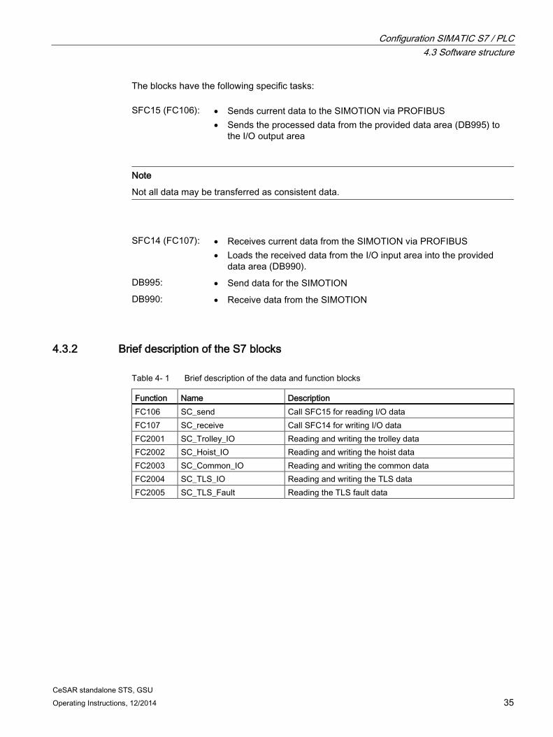
The blocks have the following specific tasks: SFC15 (FC106): • Sends current data to the SIMOTION via PROFIBUS
• Sends the processed data from the provided data area (DB995) to the I/O output area
Note
Not all data may be transferred as consistent data.
SFC14 (FC107): • Receives current data from the SIMOTION via PROFIBUS
• Loads the received data from the I/O input area into the provided data area (DB990).
DB995: • Send data for the SIMOTION DB990: • Receive data from the SIMOTION
4.3.2 Brief description of the S7 blocks
Table 4- 1 Brief description of the data and function blocks
Function Name Description FC106 SC_send Call SFC15 for reading I/O data FC107 SC_receive Call SFC14 for writing I/O data FC2001 SC_Trolley_IO Reading and writing the trolley data FC2002 SC_Hoist_IO Reading and writing the hoist data FC2003 SC_Common_IO Reading and writing the common data FC2004 SC_TLS_IO Reading and writing the TLS data FC2005 SC_TLS_Fault Reading the TLS fault data
CeSAR standalone STS, GSU 36 Operating Instructions, 12/2014
4.4 PROFIBUS DP "PLC - sway control system" interface
4.4.1 General
General information on the interface description
The input and output data is described in the tables below as follows: Column Content Signal name
Short form of the designation that is used in the S7 sample blocks or in other parts of the documentation
Format Exact type specification SINT, INT, DINT signed 8-, 16-, 32-bit number USINT unsigned 8-bit number WORD 16 bits
Address Consecutive number of the bytes, starting with 0 Remark Additional information about the value transmitted Unit Describes the unit and therefore size of the values to be transferred
The specified addresses are relative addresses, to which an offset (start address) may have to be added.
CeSAR standalone STS, GSU Operating Instructions, 12/2014 37
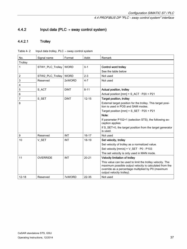
4.4.2 Input data (PLC → sway control system)
4.4.2.1 Trolley
Table 4- 2 Input data trolley, PLC → sway control system
No. Signal name Format Addr. Remark Trolley 1 STW1_PLC_Trolley WORD 0-1 Control word trolley
See the table below 2 STW2_PLC_Trolley WORD 2-3 Not used 3 Reserved 2xWORD 4-7 Not used 4 5 S_ACT DINT 8-11 Actual position, trolley
Actual position [mm] = S_ACT · P20 + P21 6 7 S_SET DINT 12-15 Target position, trolley
External target position for the trolley. This target posi-tion is used in POS and SAM modes. Target position [mm] = S_SET · P20 + P21 Note: If parameter P102=1 (selection STS), the following ex-ception applies: If S_SET=0, the target position from the target generator is used.
8
9 Reserved INT 16-17 Not used 10 V_SET INT 18-19 Set velocity, trolley
Set velocity of trolley as a normalized value. Set velocity [mm/s] = V_SET · P0 : P103 The set velocity is only used in MAN mode.
11 OVERRIDE INT 20-21 Velocity limitation of trolley This value can be used to limit the trolley velocity. The maximum possible output velocity is calculated from the override as a percentage multiplied by P0 (maximum output velocity trolley).
CeSAR standalone STS, GSU 38 Operating Instructions, 12/2014
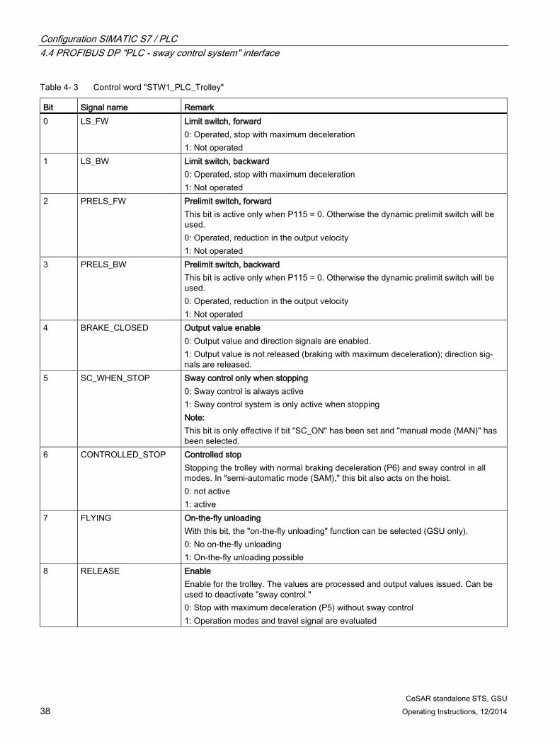
Table 4- 3 Control word "STW1_PLC_Trolley"
Bit Signal name Remark 0 LS_FW Limit switch, forward
0: Operated, stop with maximum deceleration 1: Not operated
1 LS_BW
Limit switch, backward 0: Operated, stop with maximum deceleration 1: Not operated
2 PRELS_FW
Prelimit switch, forward This bit is active only when P115 = 0. Otherwise the dynamic prelimit switch will be used. 0: Operated, reduction in the output velocity 1: Not operated
3 PRELS_BW Prelimit switch, backward This bit is active only when P115 = 0. Otherwise the dynamic prelimit switch will be used. 0: Operated, reduction in the output velocity 1: Not operated
4 BRAKE_CLOSED
Output value enable 0: Output value and direction signals are enabled. 1: Output value is not released (braking with maximum deceleration); direction sig-nals are released.
5 SC_WHEN_STOP
Sway control only when stopping 0: Sway control is always active 1: Sway control system is only active when stopping Note: This bit is only effective if bit "SC_ON" has been set and "manual mode (MAN)" has been selected.
6 CONTROLLED_STOP
Controlled stop Stopping the trolley with normal braking deceleration (P6) and sway control in all modes. In "semi-automatic mode (SAM)," this bit also acts on the hoist. 0: not active 1: active
7 FLYING On-the-fly unloading With this bit, the "on-the-fly unloading" function can be selected (GSU only). 0: No on-the-fly unloading 1: On-the-fly unloading possible
8 RELEASE Enable Enable for the trolley. The values are processed and output values issued. Can be used to deactivate "sway control." 0: Stop with maximum deceleration (P5) without sway control 1: Operation modes and travel signal are evaluated
CeSAR standalone STS, GSU Operating Instructions, 12/2014 39
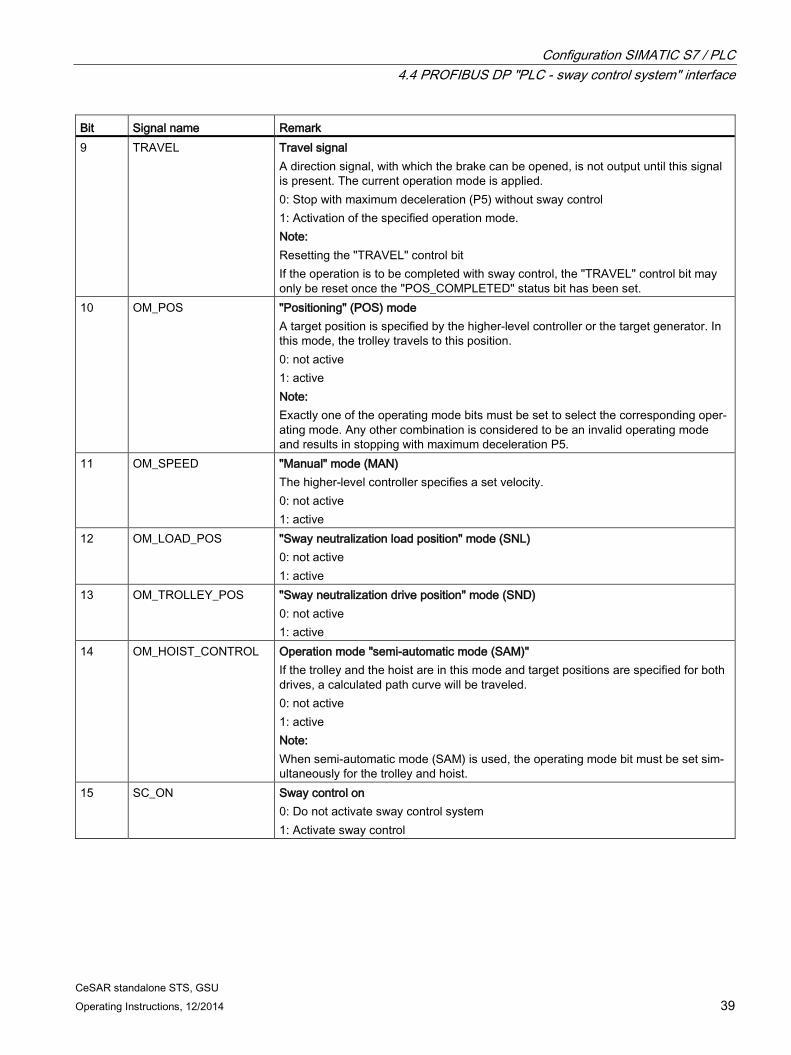
Bit Signal name Remark 9 TRAVEL Travel signal
A direction signal, with which the brake can be opened, is not output until this signal is present. The current operation mode is applied. 0: Stop with maximum deceleration (P5) without sway control 1: Activation of the specified operation mode. Note: Resetting the "TRAVEL" control bit If the operation is to be completed with sway control, the "TRAVEL" control bit may only be reset once the "POS_COMPLETED" status bit has been set.
10 OM_POS "Positioning" (POS) mode A target position is specified by the higher-level controller or the target generator. In this mode, the trolley travels to this position. 0: not active 1: active Note: Exactly one of the operating mode bits must be set to select the corresponding oper-ating mode. Any other combination is considered to be an invalid operating mode and results in stopping with maximum deceleration P5.
11 OM_SPEED "Manual" mode (MAN) The higher-level controller specifies a set velocity. 0: not active 1: active
12 OM_LOAD_POS "Sway neutralization load position" mode (SNL) 0: not active 1: active
13 OM_TROLLEY_POS "Sway neutralization drive position" mode (SND) 0: not active 1: active
14 OM_HOIST_CONTROL
Operation mode "semi-automatic mode (SAM)" If the trolley and the hoist are in this mode and target positions are specified for both drives, a calculated path curve will be traveled. 0: not active 1: active Note: When semi-automatic mode (SAM) is used, the operating mode bit must be set sim-ultaneously for the trolley and hoist.
15 SC_ON Sway control on 0: Do not activate sway control system 1: Activate sway control
CeSAR standalone STS, GSU 40 Operating Instructions, 12/2014
4.4.2.2 Hoist
Table 4- 4 Input data hoist, PLC → sway control system
No. Signal name Format Addr. Remark Hoist 19 STW1_PLC_Hoist
WORD 36-37 Control word hoist
See the table below 20 STW2_PLC_Hoist WORD 38-39 Not used 21 Reserved 2xWORD 40-43 Not used 22 23 S_ACT DINT 44-47 Hoist actual position
The hoist position must increase from the ground upward. The value specified here is used for all modes. The conversion of the hoisting position to an effective pendulum length is performed with the aid of parameters. in ± mm
24
25 S_SET DINT 48-51 Target position, hoist External target position for the hoist. This tar-get position is used in POS and SAM modes. in ± mm Note: If parameter P102=1 (selection STS), the fol-lowing exception applies: If S_SET=0, the target position from the target generator is used.
26
Reserved INT 52-53 Not used 27 V_SET INT 54-55 Set velocity, hoist
Set velocity of hoist as normalized value. Set velocity [mm/s] = V_SET · P40 : P103 The set velocity is only used in MAN mode.
28 OVERRIDE INT 56-57 Velocity limitation hoist This value can be used to limit the speed in all operating modes. The maximum possible output velocity is calcu-lated from the override as a percentage multi-plied by P40 (maximum output velocity hoist).
CeSAR standalone STS, GSU Operating Instructions, 12/2014 41
Table 4- 5 Control word "STW1_PLC_Hoist"
Bit Name Meaning 0 LS_UP Limit switch up
0: Operated, stop with maximum deceleration 1: Not operated
1 LS_DN Limit switch down 0: Operated, stop with maximum deceleration 1: Not operated
2 PRELS_UP Prelimit switch up This bit is active only when P115 < 1. Otherwise the dynamic prelimit switch will be used. 0: Operated, reduction in the output velocity 1: Not operated
3 PRELS_DN Prelimit switch down This bit is active only when P115 < 1. Otherwise the dynamic prelimit switch will be used. 0: Operated, reduction in the output velocity 1: Not operated
4 BRAKE_CLOSED Output value enable 0: Output value and direction signals are enabled. 1: Output value is not released (braking with maximum deceleration); direction signals are released
5 - Not used 6 CONTROLLED_STOP Controlled stop
Stop the hoist with normal deceleration (P51) in all operating modes. 0: not active 1: active
7 - Not used 8 RELEASE Enable
Enable for the hoist. The values are processed and output values issued. Can be used to deactivate "sway control." 0: Stop with maximum deceleration (P50)
9 TRAVEL Travel signal A direction signal, with which the brake can be opened, is not output until this signal is present. The current operation mode is applied. 0: Stop with maximum deceleration (P50) without sway control 1: Activation of the specified operation mode.
10 OM_POS "Positioning" mode (POS) A target position is specified by the higher-level controller or the target generator. In this mode, the hoist travels to this position. 0: not active 1: active
CeSAR standalone STS, GSU 42 Operating Instructions, 12/2014
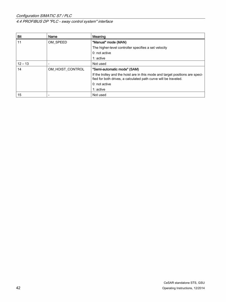
Bit Name Meaning 11 OM_SPEED "Manual" mode (MAN)
The higher-level controller specifies a set velocity 0: not active 1: active
12 – 13 - Not used 14 OM_HOIST_CONTROL "Semi-automatic mode" (SAM)
If the trolley and the hoist are in this mode and target positions are speci-fied for both drives, a calculated path curve will be traveled. 0: not active 1: active
CeSAR standalone STS, GSU Operating Instructions, 12/2014 43
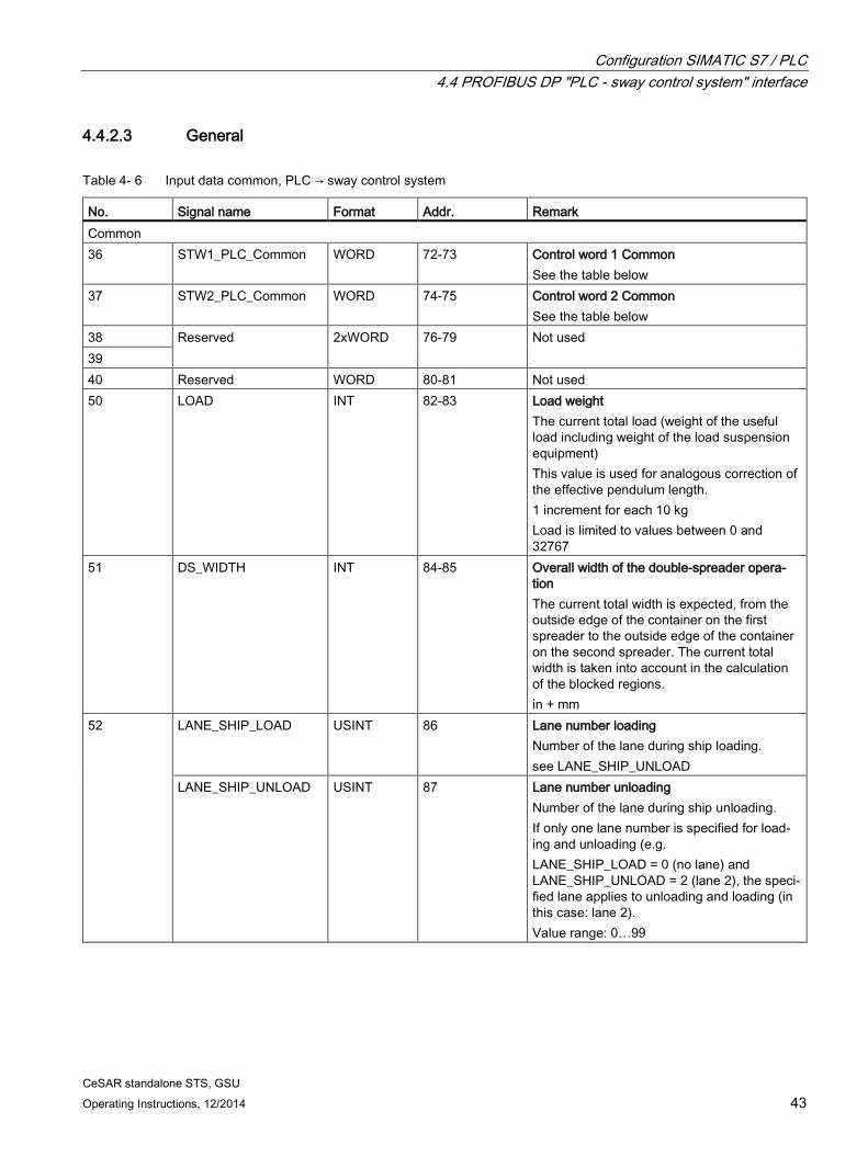
4.4.2.3 General
Table 4- 6 Input data common, PLC → sway control system
No. Signal name Format Addr. Remark Common 36 STW1_PLC_Common WORD 72-73 Control word 1 Common
See the table below 37 STW2_PLC_Common WORD 74-75 Control word 2 Common
See the table below 38 Reserved 2xWORD 76-79 Not used 39 40 Reserved WORD 80-81 Not used 50 LOAD INT 82-83 Load weight
The current total load (weight of the useful load including weight of the load suspension equipment) This value is used for analogous correction of the effective pendulum length. 1 increment for each 10 kg Load is limited to values between 0 and 32767
51 DS_WIDTH INT 84-85 Overall width of the double-spreader opera-tion The current total width is expected, from the outside edge of the container on the first spreader to the outside edge of the container on the second spreader. The current total width is taken into account in the calculation of the blocked regions. in + mm
52 LANE_SHIP_LOAD USINT 86 Lane number loading Number of the lane during ship loading. see LANE_SHIP_UNLOAD
LANE_SHIP_UNLOAD USINT 87 Lane number unloading Number of the lane during ship unloading. If only one lane number is specified for load-ing and unloading (e.g. LANE_SHIP_LOAD = 0 (no lane) and LANE_SHIP_UNLOAD = 2 (lane 2), the speci-fied lane applies to unloading and loading (in this case: lane 2). Value range: 0…99
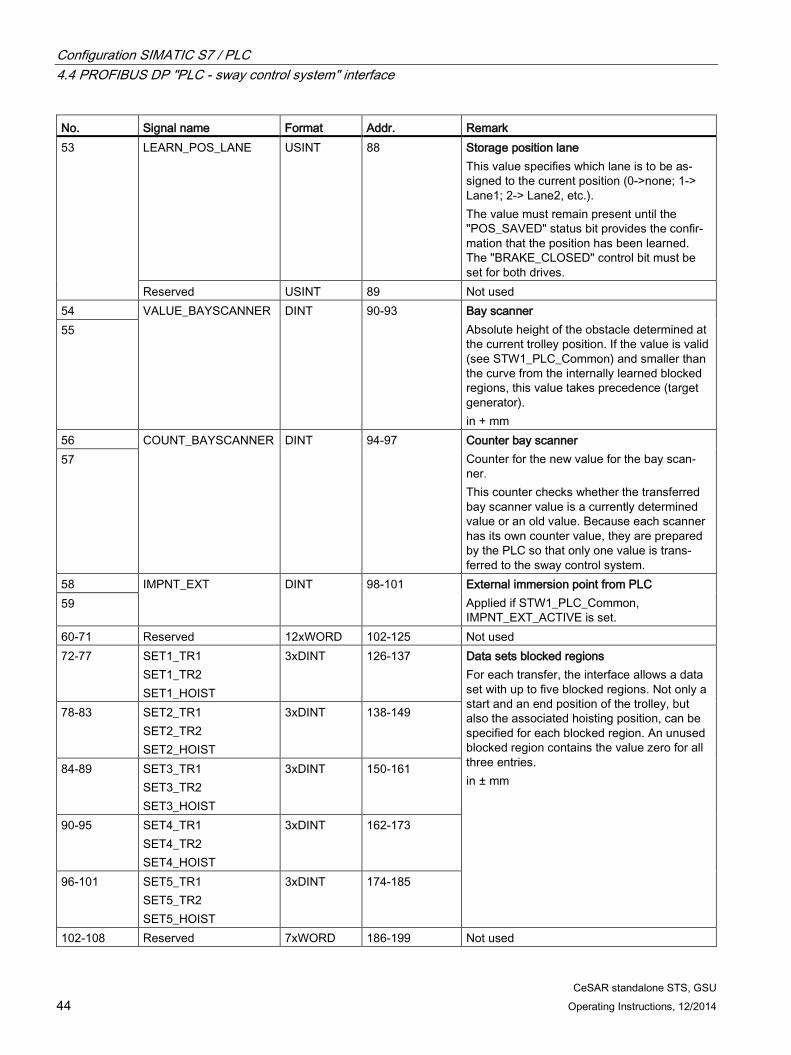
CeSAR standalone STS, GSU 44 Operating Instructions, 12/2014
No. Signal name Format Addr. Remark 53 LEARN_POS_LANE USINT 88 Storage position lane
This value specifies which lane is to be as-signed to the current position (0->none; 1-> Lane1; 2-> Lane2, etc.). The value must remain present until the "POS_SAVED" status bit provides the confir-mation that the position has been learned. The "BRAKE_CLOSED" control bit must be set for both drives.
Reserved USINT 89 Not used 54 VALUE_BAYSCANNER DINT 90-93 Bay scanner
Absolute height of the obstacle determined at the current trolley position. If the value is valid (see STW1_PLC_Common) and smaller than the curve from the internally learned blocked regions, this value takes precedence (target generator). in + mm
55
56 COUNT_BAYSCANNER DINT 94-97 Counter bay scanner Counter for the new value for the bay scan-ner. This counter checks whether the transferred bay scanner value is a currently determined value or an old value. Because each scanner has its own counter value, they are prepared by the PLC so that only one value is trans-ferred to the sway control system.
57
58 IMPNT_EXT DINT 98-101 External immersion point from PLC Applied if STW1_PLC_Common, IMPNT_EXT_ACTIVE is set.
59
60-71 Reserved 12xWORD 102-125 Not used 72-77 SET1_TR1
SET1_TR2 SET1_HOIST
3xDINT 126-137 Data sets blocked regions For each transfer, the interface allows a data set with up to five blocked regions. Not only a start and an end position of the trolley, but also the associated hoisting position, can be specified for each blocked region. An unused blocked region contains the value zero for all three entries. in ± mm
CeSAR standalone STS, GSU Operating Instructions, 12/2014 45
Table 4- 7 Control word "STW1_PLC_Common"
Bit Name Meaning 0 LOCKED_BIT0 Locking state of the spreader
00 No spreader locked 01/10: Spreaders are partly locked Spreaders are partly locked, • when only one spreader of a double spreader in tandem mode has been
locked or • a 20-foot container has been locked on a spreader at maximum width. The travel curves are calculated as required with loaded spreader. The automatic learning does not take account of the height of the locked con-tainer. 11: Spreaders are completely locked. The travel curves are calculated as required with loaded spreader. The lower edge of the container(s) is used to learn the blocked regions.
1
LOCKED_BIT1
2
SLACKROPE
Slack rope 0: No slack rope 1: Slack rope available
3
BAYSCANNER_VALID
Bay scanner value valid 0: Bay scanner values not valid 1: Values from bay scanner valid
4
LEARN_PROFILE_ON
Learn height profile LEARN_PROFILE_ON
LEARN_PROFILE_RESET
Learn mode
0 0 A: Obstacle profile is not updated 0 1 B: Delete the height profile 1 0 C: Learn the height profile (regular
operation) 1 1 D: Delete the height profile Only learn mode C is provided for automatic operation. The modes B or D are functionally equivalent and required only for the initialization and should remain selected until the "LEARN_PROFILE_RESET_OK" confirmation bit indicates the successful deletion of the internally learned variable obstacles. Mode C must then be selected again.
5
LEARN_PROFILE_RESET Delete height profile see preceding description for the bit "LEARN_PROFILE_ON"
6 IMPNT_EXT_ACTIVE Activate external immersion point The current immersion point is switched between the internal and the ex-ternal immersion point with the bit. 0: Activate internal immersion point 1: Activate external immersion point Switchover is only possible if "semi-automatic mode" is not active. For fur-ther information on the immersion point (see Chapter Further functions in "semi-automatic mode" (SAM) (Page 114)).
CeSAR standalone STS, GSU 46 Operating Instructions, 12/2014
Bit Name Meaning 7 SPREADERS_COUPLED Spreaders coupled
The bit indicates whether the two spreaders are coupled when using a double spreader. This affects the width for the specification of the blocked regions and so the calculation of the path curve. 0: Spreader not coupled 1: Spreaders coupled
8 PAR_SET_BIT0 Select parameter set Bit combination for the selection of the parameter set: 9 PAR_SET_BIT1 Par_Set_Bit1 Par_Set_Bit0 0 0 Parameter set 1 0 1 Parameter set 2 1 0 Parameter set 3 1 1 Parameter set 4 The parameter P101 "Parameter set locked during travel" can be used to specify whether switchover of the current parameter set is permissible at any time or only at standstill.
10 NO_WAIT_POS Do not approach waiting position This bit specifies whether the waiting position defined in the P25 (trolley) and P65 (hoist) parameters is to be approached. 0: Approach waiting position 1: Do not approach waiting position
11 PRG_OBST Program blocked regions Transfer of the external variable blocked regions used to calculate the path curve. Zero data sets are ignored. 0: Do not take over 1: Take over
12 DEL_OBST Delete blocked regions Deletion of the external variable blocked regions 0: Do not delete 1: Delete Note: The "DEL_OBST" bit deletes only the external learned variable blocked regions. The internally learned variable blocked regions are retained. This means it must be known beforehand how many internally learned variable blocked regions are required so that the total number of 200 is not exceed-ed. For the maximum number of external variable blocked regions that can be transferred, the following is true: maximum value = 200 – maximum number of internally learned blocked regions If the bits "PRG_OBST" and "DEL_OBST" are set simultaneously, all trans-ferrable, external, variable blocked regions will be deleted.
13 PLC_COMM_OK Life bit for SIMOTION 0: Connection to the PLC is interrupted 1: Connection to the PLC is active
CeSAR standalone STS, GSU Operating Instructions, 12/2014 47
Bit Name Meaning 14 - Not used 15 START_2D_CALC Start 2D calculation
Bit indicates that calculation of the path curve can start. It should be set when all blocked regions have been transferred completely. The automatic mode performs the path calculation and starts travel. 0: not active 1: active Note: As soon as this bit is reset, the crane stops in SAM mode under sway con-trol.
Table 4- 8 Control word "STW2_PLC_Common"
Bit Name Meaning 0 OFFSET_TO_LAND Offset landside
When positioning the trolley, an offset toward the landside is added to the target position. 0: Offset landside is not active 1: Offset landside is active
1 OFFSET_TO_WATER Offset waterside When positioning the trolley, an offset toward the waterside is added to the target position. 0: Offset waterside is not active 1: Offset waterside is active
2 DIG_HOIST_DIST_CORR Digital "effective pendulum length correction" With this bit, for example, displacement of the center of gravity caused by various load suspension devices and the resulting change of the effective pendulum length is taken into consideration. If this bit is set, the effective pendulum length is changed by a specified amount (parameter 80). 0: not active 1: active
3-7 - Not used 8 LEARN_PARK_POS Save parking position
This bit is used for saving the current position as parking position. 0: Do not save parking position 1: Save parking position The control bit must remain present until the "POS_SAVED" status bit pro-vides the confirmation that the position has been learned. The "BRAKE_CLOSED" control bit must be set for both drives. After the learning, the control bit must be reset.
CeSAR standalone STS, GSU 48 Operating Instructions, 12/2014
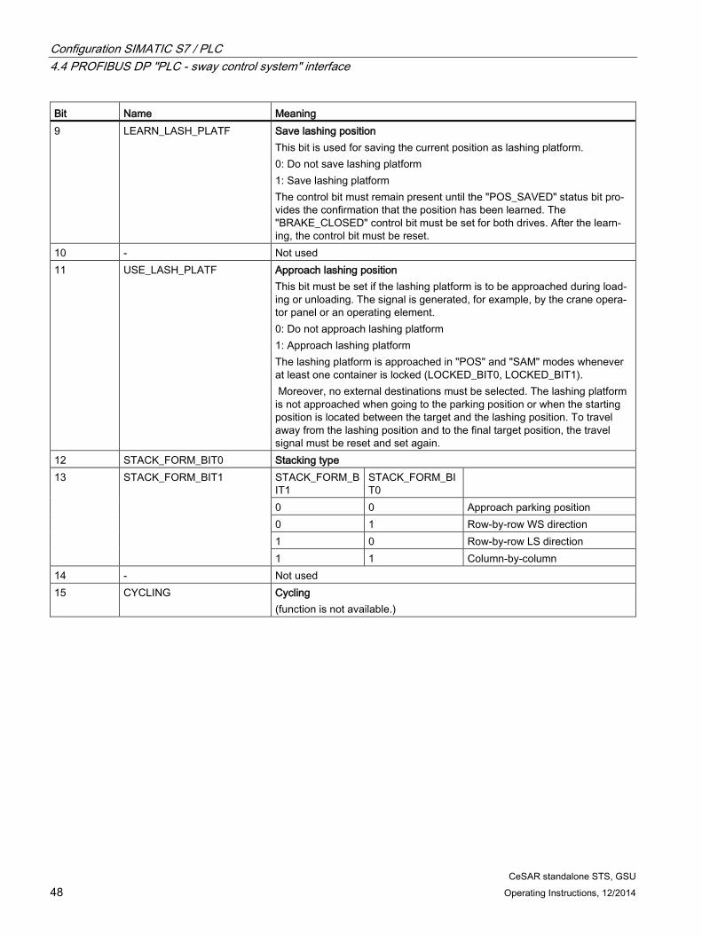
Bit Name Meaning 9 LEARN_LASH_PLATF Save lashing position
This bit is used for saving the current position as lashing platform. 0: Do not save lashing platform 1: Save lashing platform The control bit must remain present until the "POS_SAVED" status bit pro-vides the confirmation that the position has been learned. The "BRAKE_CLOSED" control bit must be set for both drives. After the learn-ing, the control bit must be reset.
10 - Not used 11 USE_LASH_PLATF Approach lashing position
This bit must be set if the lashing platform is to be approached during load-ing or unloading. The signal is generated, for example, by the crane opera-tor panel or an operating element. 0: Do not approach lashing platform 1: Approach lashing platform The lashing platform is approached in "POS" and "SAM" modes whenever at least one container is locked (LOCKED_BIT0, LOCKED_BIT1). Moreover, no external destinations must be selected. The lashing platform is not approached when going to the parking position or when the starting position is located between the target and the lashing position. To travel away from the lashing position and to the final target position, the travel signal must be reset and set again.
12 STACK_FORM_BIT0 Stacking type 13 STACK_FORM_BIT1 STACK_FORM_B
IT1 STACK_FORM_BIT0
0 0 Approach parking position 0 1 Row-by-row WS direction 1 0 Row-by-row LS direction 1 1 Column-by-column
4xDINT 208-223 Position of the TLS hydraulic cylin-ders A,B,C,D Position data from four hydraulic cylinders, which is used for the trim, list, skew and skew control. The usage of the position data is speci-fied with the aid of parameters. in ± mm
121 Ext_SkewPos_for_TLS_BA DINT 224-227 External set skew External value for the set skew of the spreader by a specified angle. in ± cgr
122
123-130 - 4xWORD 228-235 Not used 131 SkewPos_Set DINT 236-239 Set position electric skew axis
for external position mode in ± mm
132
133 WORD 240-241 Not used 134 WORD 242-243 Not used
CeSAR standalone STS, GSU 50 Operating Instructions, 12/2014
Table 4- 10 Control word "STW1_PLC_TLS"
Bit Name Meaning 0 save_zero
Save zero position 0: No command 1: Save current cylinder positions as zero positions command Remark If move = 0, the parameters P250 to P253 in the parameter sets are overwritten as zero positions according to the current cylinder posi-tions.
1 skew_target_ext
External rotational position In "TLS positioning" mode, the target position for skew is defined via the input signal S_SKEW_EXTERN.
2 spreader_bit0
Spreader bits 0 and 1 for transferring the current spreader length spreader_bit0=0, spreader_bit1=0 → Container 20 ft spreader_bit0=1, spreader_bit1=0 → Container 30 ft spreader_bit0=0, spreader_bit1=1 → Container 40 ft spreader_bit0=1, spreader_bit1=1 → Container 45 ft The bits must be set appropriately for the spreader length.
3 spreader_bit1
4 - Not used 5 move Activation of the cylinder position control 6 mode_comm Activates "cylinder inching" mode 7 tls_pos Activates "TLS positioning" mode 8 trim_right Trim right ("TLS inching" mode)
Spreader: A, B up / C, D down 0: No command 1: Incline to the right command
9 trim_left Trim left ("TLS inching" mode) Cylinders: A, B in / C, D out Spreader: A, B down / C, D up 0: No command 1: Incline to the left command
10 list_water List water ("TLS inching" mode) Spreader: B, C down / A, D up 0: No command 1: Incline to the waterside command
11 list_land List land ("TLS inching" mode) Spreader: B, C up / A, D down 0: No command 1: Incline to the landside command
12 skew_clockwise Skew clockwise Cylinders: A, C in / B, D out Spreader: A, C down / B, D up 0: No command 1: Rotate in clockwise direction command
CeSAR standalone STS, GSU 52 Operating Instructions, 12/2014
Table 4- 11 Control word "STW2_PLC_TLS"
Bit Name Meaning 0 a_in_comm Control cylinder A with negative velocity 1 b_in_comm Control cylinder B with negative velocity 2 c_in_comm Control cylinder C with negative velocity 3 d_in_comm Control cylinder D with negative velocity 4 a_out_comm Control cylinder A with positive velocity 5 b_out_comm Control cylinder B with positive velocity 6 c_out_comm Control cylinder C with positive velocity 7 d_out_comm Control cylinder D with positive velocity 8 Skewpos_ext Set position for the electric skew axis is specified from an external
source. 9 Ska_in_comm Travel of the skew axis (negative velocity) via the internal setpoint
generator 10 Ska_out_comm Travel of the skew axis (positive velocity) via the internal setpoint
generator 11 Move_ska Activation of the position control of the skew axis 12 Reset_mdl Resetting an internal oscillation model 13 Hold_trim_list Hold the trim and list positions 14-15 - Not used
CeSAR standalone STS, GSU Operating Instructions, 12/2014 53
4.4.3 Output data (sway control system → PLC)
4.4.3.1 Trolley
Table 4- 12 Output data trolley; sway control system → PLC
No. Signal name Format Addr. Remark 1 ZSW1_PLC_Trolley WORD 0-1 Status word 1 trolley
See table below 2 ZSW2_PLC_Trolley WORD 2-3 Not used 3 V_POS INT 4-5 Output velocity, trolley
This value is output normalized. The following applies: V_POS = output velocity [mm/s] ·P103 : P0
4 A_POS INT 6-7 Output acceleration, trolley This value is output normalized. The following applies: A_POS = output acceleration [mm/s²] · P103 : P5.
5 LOAD_DEFL_TR INT 8-9 Current pendulum deflection Current distance of the reflector from its home position in the direction of the trolley in ± mm. • STS (with camera measuring system)
The value corresponds to the pendulum deflection measured by the camera measuring system.
The following applies: LOAD_DEFL_TR = IY_POS (or IX_POS)
If the camera measuring system fails, the deflection is zero for the duration of the "Tripping time for camera error" (P127). If the tripping time (P127) has expired and error E4 is present, the deflection corresponds to the value from the mathematical oscillation model.
• GSU (without camera measuring system) The value corresponds to a calculated quantity. With travel command = 0, this value also becomes zero.
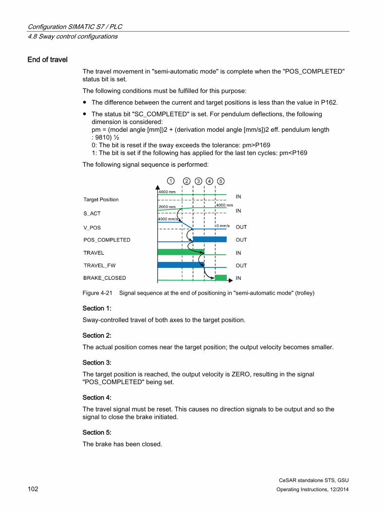
The set velocity is greater than zero or the output velocity is greater than the zero speed detection P3 or SC_COMPLETED=0. Positioning, sway neutralization, and semi-automatic mode: POS_COMPLETED is reset if the distance between the actual position and the target position is greater than the positioning accuracy P162 or SC_COMPLETED=0.
1 Operation mode manual: For 25 cycles, the following applies: The set velocity (V_SET) is zero and the output velocity (V_POS) is less than or equal to the zero speed detection P3 and SC_COMPLETED=1. Operation mode Positioning, sway neutralization, and semi-automatic mode: POS_COMPLETED is set if the distance between the actual position and the target position is less than the positioning accuracy P162 and SC_COMPLETED=1. A time delay of 25 cycles is applied.
11
SC_COMPLETED
Sway-neutralized The following is measure is considered for sway: pm = (model angle [mm]) 2 + (derivation model angle [mm/s])2 eff. pendulum length : 9810)½ 0: The bit is set if the sway exceeds the tolerance: pm>P169 1: The bit is set if the following has applied for the last ten cycles: pm<P169
12 TRAVEL_FW
Direction of travel forward 0 All modes:
The "TRAVEL" control bit is zero or the output velocity is less than or equal to the zero speed detection P3 or an error message is pending that prevents travel.
1 Operation mode manual: The "TRAVEL" control bit is set and the set velocity is greater than or equal to zero or the output velocity is positive and greater than the zero speed detec-tion P3. Positioning, sway neutralization, and semi-automatic mode: The "TRAVEL" control bit is set and the difference between the target position and the current position is greater than or equal to zero or the output velocity is positive and greater than the zero speed detection P3.
CeSAR standalone STS, GSU Operating Instructions, 12/2014 55
Bit Name Meaning 13 TRAVEL_BW Direction of travel backward
0 All modes: The "TRAVEL" control bit is zero or the output velocity is less than or equal to the zero speed detection P3 or an error message is pending that prevents travel.
1 Operation mode manual: Control bit "TRAVEL" is set and the set velocity is less than zero. The output velocity is negative and greater than the zero speed detection P3. Positioning, sway neutralization, and semi-automatic mode: The "TRAVEL" control bit is set and the difference between the target position and the current position is less than zero or the output velocity is negative and greater than the zero speed detection P3.
14 Used internally Reserved 15 SC_STATE Sway control on
0: The sway control function is active 1: The sway control function is not active
The set velocity is greater than zero or the output velocity is greater than the zero speed detection P144 or SC_COMPLETED=0. Positioning, sway neutralization, and semi-automatic mode: POS_COMPLETED is reset if the distance between the actual position and the target position is greater than the positioning accuracy P162 or SC_COMPLETED=0.
1 Operation mode manual: For 25 cycles, the following applies: The set velocity (V_SET) is zero and the output velocity (V_POS) is less than or equal to the zero speed detection P44 and SC_COMPLETED=1. Positioning, sway neutralization, and semi-automatic mode: POS_COMPLETED is set if the distance between the actual position and the target position is less than the positioning accu-racy P165. A time delay of 25 cycles is applied.
CeSAR standalone STS, GSU Operating Instructions, 12/2014 57
Bit Name Meaning 11 - Not used 12
TRAVEL_UP
Direction of travel up 0 All modes:
The "TRAVEL" control bit is zero or the output velocity is less than or equal to the zero speed detection P44 or an error mes-sage is pending that prevents travel.
1 Operation mode manual: The "TRAVEL" control bit is set and the set velocity is greater than or equal to zero or the output velocity is positive and great-er than the zero speed detection P44. Positioning, sway neutralization, and semi-automatic mode: The "TRAVEL" control bit is set and the difference between the target position and the current position is greater than or equal to zero or the output velocity is positive and greater than the zero speed detection P44.
13
TRAVEL_DN
Lower travel direction (path values become smaller) 1 All modes:
The "TRAVEL" control bit is zero or the output velocity is less than or equal to the zero speed detection P44 or an error mes-sage is pending that prevents travel.
0 Operation mode manual: Control bit "TRAVEL" is set and the set velocity is less than zero. The output velocity is negative and greater than the zero speed detection P44. Positioning, sway neutralization, and semi-automatic mode: The "TRAVEL" control bit is set and the difference between the target position and the current position is less than zero or the output velocity is negative and greater than the zero speed detection P44.
CeSAR standalone STS, GSU 58 Operating Instructions, 12/2014
4.4.3.3 General
Table 4- 16 Output data common; sway control system → PLC
No. Signal name Format Addr. Remark 45 ZSW1_Common_PLC WORD 108-
109 Status word common See the table "ZSW1_Common_PLC" below
46 ZSW2_Common_PLC WORD 110-111 Not used 47 INFO_NO_AUTO_START 2xWORD 112-115 Information automatic start
Contains information for the visualization about why an automatic start is not possible ("START_AUTO_OK" is not set). See table below, Status word for crane oper-ator panel ("INFO_NO_AUTO_START")
48
49-60 Reserved 12xWORD 116-139 Not used 61 FAULT1 2xWORD 140-143 Error message 1
Address 140-141 contains the error bits 16-31; address 142-143 contains the error bits 0-15 (see Error messages (Page 246))
62
63 FAULT2 2xWORD 144-147 Error message 2 Addresses 144 to 147 are used by the TLS 64
65 NUMBER_OBST INT 148-149 Number of blocked regions This consists of the number of blocked re-gions transferred externally via the interface plus the number of internally learned blocked regions.
66 LANE_LOAD_OK USINT 150 Confirmation lane number loading This signal can, for example, be forwarded to the crane operator panel or used by the PLC to release the automatic. Automatic may be permitted only when the signaled value and the confirmed value are identical. Value range: 0-99
LANE_UNLOAD_OK USINT 151 Confirmation lane number unloading This signal can, for example, be forwarded to the crane operator panel or used by the PLC to release the automatic. Automatic may be permitted only when the signaled value and the confirmed value are identical. Value range: 0-99
67 IMPNT DINT 152-155 Value of the current immersion point As the current immersion point, either the internal or external immersion point is used, depending on the "IMPNT_EXT_ACTIVE" control bit. in + mm
CeSAR standalone STS, GSU Operating Instructions, 12/2014 59
Table 4- 17 Status word for crane operator panel ("ZSW1_Common_PLC")
Bit Name Meaning 0 OPEN_GRAB Open grab (GSU only)
0: Do not open grab 1: The grab can be opened This bit is used as a control signal for opening the grab. The time of setting is specified by parameter P31; the time of resetting is specified by parame-ter P30. OPEN_GRAB is only used if on-the-fly unloading (input bit FLYING) is activated and if selection "3" is activated in parameter 152.
1 CAMERA_OK Camera OK 0: Measured values from camera (SIMOCRANE CenSOR) are invalid or communication is down. 1: Camera (SIMOCRANE CenSOR) provides valid values and communica-tion is up.
2 EXT_IMPNT_SMALLER External immersion point less than internal immersion point 0: External immersion point >= internal immersion point 1: Ext. immersion point < int. immersion point Note: If the external immersion point is less than the internal immersion point, it must be ensured in the higher-level controller that travel is possible without a risk of collision.
3 POS_IN_SAFETY_AREA Actual position in a safety area (monitoring) 0: Actual position outside a safety area 1: Actual position in a safety area Note: The spreader is moved into a safety area in "semi-automatic mode (SAM)." An attempt is made to move out of this area again with sway control.
4 LEARN_PROFILE_ON_OK Height profile learned Confirmation of the control bit for "LEARN_PROFILE_ON."
5 LEARN_PROFILE_RESET_OK Height profile deleted Confirmation of the control bit "LEARN_PROFILE_RESET." The height profile has been deleted.
6 START_AUTO_OK Automatic, start permitted 1: Conditions for starting automatic met 0: Conditions for starting automatic not met Bit for enabling automatic without triggering an error message. A precise breakdown of why a start is not possible can be obtained from the table below "Status word for crane operator panel ("INFO_NO_AUTO_START")." A group bit can also be formed from signal messages by the PLC. In this way, specific functions can be permitted for automatic travel (e.g. start from slack rope on the waterside). Note: Without the appropriate evaluation of this bit or the individual bits from the table below "Status word for crane operator panel ("INFO_NO_AUTO_START")" in the PLC, under some circumstances the automatic can also be started when this bit is not set.
CeSAR standalone STS, GSU 60 Operating Instructions, 12/2014
Bit Name Meaning 7 HOIST_TAKEOVER_OK Hoist takeover allowed
This bit is set at the height above which trolley positioning motion starts. A manual takeover of the hoist is possible as of this time. If this bit is not set, no manual control for the hoist may be permitted during the automatic trolley travel. A collision with obstacles could occur. In this case, the automatic must be aborted for the trolley and the hoist. 1 = Hoist takeover permitted 0 = Hoist takeover not permitted
8 PARSET_BIT0 Parameter set active Bit combination for confirmation of the active parameter set
9 PARSET_BIT1 PARSET_BIT1 PARSET_BIT0 0 0 Parameter set 1 0 1 Parameter set 2 1 0 Parameter set 3 1 1 Parameter set 4
10 NO_WAIT_POS_OK Waiting position is not approached Confirmation of the common control bit "NO_WAIT_POS." This bit specifies whether a waiting position, defined from the trolley and the hoisting position, is to be approached. The positions are defined in the P25 (trolley) and P65 (hoist) parameters. 0: not active 1: active
11 PRG_OBST_OK Blocked regions programmed Confirmation of the common control bit "PRG_OBST." The blocked regions are taken over.
12 OBST_DELETED Blocked regions deleted Confirmation of the common control bits "DEL_OBST." The blocked regions have been deleted.
13 WATCH_DOG Watchdog (200 ms) Signal flashes in the 200-ms cycle
14 CHANGE_TARGET Target switchover (GSU only) 0 – Request target on the landside 1 – Request target on the waterside If on-the-fly unloading is active, the bit will be set at the same time as the "Grab Open" bit. If on-the-fly unloading is not active, the bit is set if the target position is reached on the landside within the positioning accuracy (P162). If the travel signal is reset, this bit will also be reset irrespective of whether on-the-fly unloading is active.
CeSAR standalone STS, GSU Operating Instructions, 12/2014 61
Table 4- 18 Status world for crane operator panel ("INFO_NO_AUTO_START")
Bit Signal name Meaning 0 StartPosEqualTargetPos Starting position is same as target position
The starting position is identical with the target position. The bit will be output when the trolley position at the time of starting the automatic dif-fers by less than twice the positioning accuracy from the target position. The "START_AUTO_OK" bit is not set.
1 InitialSway (STS only)
Initial sway While the initial sway is greater than the permitted initial sway defined in P156, this bit remains set. If the initial oscillation is too large, the E62 error message will be issued at the start of an automatic travel. Automatic travel is then impossible. This affects both the waterside and the land-side.
2 SlackropeOnWS Slack rope on the waterside The bit is set if the "SLACKROPE" control bit is set and the trolley is on the waterside.
3 HoistUnderImmersionPoint Hoist below immersion point The hoist is below the immersion point. This affects only the waterside.
4 TargetPosInVarArea Target moved Automatic mode starts, but is stopped before/above the variable blocked region.
5 TargetToDeep Target too deep Only GSU: The target for the on-the-fly unloading must not be lower than the highest obstacle. If this is not the case, the automatic does not start.
6 - 7 - Not used 8 POS_SAVED Position learning successful
0: Position learning unsuccessful 1: Position learning successful This bit is used for the confirmation of the successful learning of the posi-tions for parking, lashing platform, and lane.
9 DIRECTION_LAND Next target toward landside If a target position has been entered for the trolley or determined by the target generator, which, compared with the current position, lies in the land direction, this bit is set.
10 DIRECTION_WATER Next target toward waterside If a target position has been entered for the trolley or determined by the target generator, which, compared to the current position, lies in the water direction, this bit is set.
11 TargetPosNotInLimit Target position not in permitted limits Target position is not located within the set limits for positioning.
12 StartPosNotInLimit Starting position not in permitted limits Start position is not located within the set limits for positioning.
13 StartPosInFixedArea Starting position in a fixed blocked region The current start position is in a fixed blocked region. This message can be forwarded to the crane operator panel (COP) where it is displayed as a symbol (see Operating Instructions "Crane Operator Panel").
CeSAR standalone STS, GSU 64 Operating Instructions, 12/2014
Table 4- 20 Status word ZSW1_TLS_PLC
Bit Signal name Remark 0 - Not used 1 motion_terminated_SkA Motion terminated, skew drive 2 zero Zero position reached 3 motion_terminated Motion terminated, cylinder 4 skew_removed
Skew oscillation eliminated Amplitude of the oscillation is less than P301. Note: Noisy camera signals psi_cam also cause a certain level of noise in the model angle psi_model. This can result in flickering of the skew_removed status bit. In this case, the bit should be evaluated via an additional timer in the higher-level control system.
5 - Not used 6 - Not used 7 - Not used 8 a_out Cylinder A is extended 9 b_out Cylinder B is extended 10 c_out Cylinder C is extended 11 d_out Cylinder D is extended 12 a_in Cylinder A is retracted 13 b_in Cylinder B is retracted 14 c_in Cylinder C is retracted 15 d_in Cylinder D is retracted
CeSAR standalone STS, GSU Operating Instructions, 12/2014 65
4.4.4 Limitation of input signals In the SIMOTION C, the input data of the higher-level controller is limited by a SIMOTION application.
The table below lists the limits for the input values.
Table 4- 21 Limits for the input data sway control system
Block Designation Unit Min Max Meaning Trolley OVERRIDE % 0 100 Velocity override S_ACT ± mm min. P23 max. P28 Actual position S_SET ± mm min. P23 max. P28 Target position V_SET Normalized -P103 P103 Set velocity (normalized) Hoist OVERRIDE % 0 100 Velocity override S_ACT ± mm min.P63 max. P69 Actual position S_SET ± mm min.P63 max. P69 Target position V_SET Normalized -P103 P103 Set velocity (normalized) Common LOAD Increment
for each 10 kg
0 max. INT
Load mass in steps of 10 kg
VALUE_BAYSCANNER mm min. P63 max. P69 Bay scanner COUNT_BAYSCANNER
Counters
min. DINT
max. DINT
Counter for scanner
DS_WIDTH mm 100 INT Total width, double spreader TLS Ext_SkewPos_for_TLS_BA ± 1/100 -1500 +1500 Set skew ActPos_cylinder_A ± mm
min. DINT
max. DINT
Cylinder A position
ActPos_cylinder_B ± mm
min. DINT
max. DINT
Cylinder B position
ActPos_cylinder_C ± mm
min. DINT
max. DINT
Cylinder C position
ActPos_cylinder_D ± mm min. DINT
max. DINT
Cylinder D position
ActPos_SkewAxis ± mm min. DINT
max. DINT
Actual position of skew drive
Skewpos_ext ± mm -10000 10000 Set position of skew axis
Blocked regions (via PLC) SETx_TR1 ± mm min.P23 max. P28 Trolley position 1 (5x) SETx_TR2 ± mm min.P23 max. P28 Trolley position 2 (5x) SETx_HOIST ± mm min.P63 max. P69 Hoist position (5x)
CeSAR standalone STS, GSU 66 Operating Instructions, 12/2014
Block Designation Unit Min Max Meaning Camera, not part of the DP interface [Ref. 1] X_POS ± mm min.
DINT max. DINT
Deflection X
V_X ± mm/s
min. DINT
max. DINT
Velocity X
Y_POS ± mm
min. DINT
max. DINT
Deflection Y
V_Y ± mm/s
min. DINT
max. DINT
Velocity Y
ROTATION ± cgr
min. DINT
max. DINT
Rotation
V_ROTATION ± cgr/s
min. DINT
max. DINT
Velocity skew
DIST_CAMERA ± mm
min. DINT
max. DINT
Distance from reflector
IP1 IP format 0 255 IP address byte 1 IP2 IP format 0 255 IP address byte 2 IP3 IP format 0 255 IP address byte 3 IP4 IP format 0 255 IP address byte 4 PORT IP format 0 Port number UDP Automatic LANE_SHIP_LOAD 0 99 Lane number loading LANE_SHIP_UNLOAD 0 99 Lane number unloading LEARN_POS_LANE 0 99 Storage position
If the input value is outside the set limits of the value range, the value will be set to the limit value and the status bit 20 (in the double word error message 1 of the SwayControl output data on the PLC) set.
This error bit must be evaluated by the higher-level controller because it is not visible in the CeCOMM.
Note
The number formats INT and DINT are limited as follows:
min. INT = −32.768 max. INT = +32.767 min. DINT = −2.147.483.648 max. DINT = +2.147.483.647
CeSAR standalone STS, GSU Operating Instructions, 12/2014 67
4.5 Mode-independent Logic
4.5.1 Conversion of the bay scanner values Using the bay scanner, more accurate values can be sensed from the container stack. If the bay scanner supplies a valid signal, the obstacle height determined by it is considered with priority over the learned travel curve.
Note
Depending on the installation position of the laser, the system is able to travel to the next position in automatic loading operation.
The bay scanner must be at a certain minimum distance from the center of the spreader. Otherwise there is a risk of the scanner sensing the spreader and taking it to be an obstacle.
The distance (hm) from the scanner to the surface of the container stack is measured (dashed lines; measured laser value hm). The PLC must convert this value into a laser value (hVB; vB bay scanner value) that represents the distance between the hoisting height ZERO (h0) to the upper edge of the container stack at this position (bay scanner value, see following figure). The height between two valid measuring points is direction-dependent and is set to the height of the second measuring point.
Figure 4-3 Measurement of the height of the container stack with the laser scanner
CeSAR standalone STS, GSU 68 Operating Instructions, 12/2014
Formula for calculating the obstacle height:
hVB = hs - hm
The conversion can be performed as follows in the PLC software for the evaluation of the bay scanner data:
1. Lower the spreader to the quay, and record the actual position of the hoist (Actualposition hoistQuay) and the bay scanner value (Measured laser valueQuay).
Figure 4-4 Explanation of point 1
2. From the measured laser value (Measured laser valueQuay) and the actual position of the hoist (Hoist actualpositionQuay) at a defined position, the installation height of the scanner at a defined position (scanner height hs) is defined, which can be manually calculated:
CeSAR standalone STS, GSU Operating Instructions, 12/2014 69
3. The converted laser value (bay scanner value hVB) is then calculated using the scanner height hs in the following equation and transferred with the "ValueBayscan" signal to the sway control system:
hvB = hs - hm
Figure 4-5 Explanation of point 3
hVB = 46000 mm - 31000 mm
hVB = 15000 mm
Figure 4-6 Example of conversion in SIMATIC S7
This converted laser value (Value Bay Scanner hVB) is also displayed on the display screen in Fig. 4-6 (see Chapter Monitor display screens (Page 148)).
CeSAR standalone STS, GSU 70 Operating Instructions, 12/2014
4. Check the adjustment of the bay scanner values and the hoisting height in the "Hoist control [6]" display screen. These must be approximately the same (±100 mm) as the spreader lowered to the quay.
Figure 4-7 Check the adjustment of the bay scanner values and the hoisting height
CeSAR standalone STS, GSU Operating Instructions, 12/2014 71
4.5.2 Normalization Normalization and denormalization are shown in the following diagram using a trolley as an example.
Figure 4-8 Normalization, trolley
The setpoint V_SET is denormalized with the ratio stated (indicated by a red border in the figure).
The output velocity V_POS is normalized with the ratio stated (indicated by a blue border in the figure).
Example: With P0 = 1000 mm/s and P103 = 16384, a setpoint value of V_SET = 16384 corresponds to an internal setpoint value of 1000 mm/s. If an output velocity of 100 mm/s is to be traveled, an output velocity V_POS = 1638 is provided with identical settings.
For sway control to function correctly, it must be ensured in the crane control system that the internal velocity values in mm/s match the actual velocities really measured in mm/s. These are measured, for example, with an external tachometer or by measuring the positions with a tape measure.
The normalization also applies to the acceleration (A_POS).
CeSAR standalone STS, GSU 72 Operating Instructions, 12/2014
4.5.3 Generating the "TRAVEL" control bit
WARNING
Danger to life from unexpected machine movement
For as long as the "TRAVEL" control bit remains set, unexpected movements may occur after the crane has come to a standstill, which can result in injury or death.
Cancellation by the sway control may be triggered by the control bits "RELEASE," "BRAKE_CLOSED," "CONTROLLED_STOP," and all limit switches.
"TRAVEL" must be reset by the crane control system in the event of an Emergency stop, Emergency switching off or cancellation of the continued travel. • The "TRAVEL" control bit must be activated by a deliberate action.
Travel is initiated in the sway control by setting the "TRAVEL" control bit (travel signal).
The travel signal may then be set in the crane control system if all conditions required to start travel are met, or if there is no state intended to prevent travel (e.g. emergency stop activated).
If this is the case, then the "TRAVEL" control bit can be set as soon as a corresponding actuator is activated by the crane driver (e.g. master controller in "manual" mode or start button / momentary-contact foot switch in "positioning" mode).
The "TRAVEL" control bit must be reset if a state occurs during travel which is intended to prevent continued travel. Stopping is then performed with maximum deceleration without sway control.
If the travel can be terminated without a fault, the "TRAVEL" control bit should be reset with the "POS_COMPLETED" status bit. The travel is then terminated with no residual sway and the target position is reached in "positioning" and "SAM" mode.
Operation mode "manual" When the master controller is deflected, the set velocity is transferred to the sway control; the "TRAVEL" control bit must be set simultaneously. When the master controller is released, the set velocity is set to zero; however, the travel signal must remain active until the sway control sets the status bit "POS_COMPLETED."
Fault value suppression for the set velocity in "manual mode"
Suppression of any potential fault values in the crane control system must be ensured for set velocity = 0 to prevent any unintended motion. For instance, as follows: If set velocity is less than a certain value (e.g. 0.5%), the value 0 is transmitted to the sway control.
This measure should be performed for set velocities V_SET and V_SET.
CeSAR standalone STS, GSU Operating Instructions, 12/2014 73
"Positioning" und SAM modes The "TRAVEL" control bit is formed, for example, by means of a foot switch. However, in this case, a target position is entered. The set velocity (V_SET) is not used in this mode. It is positioned with positioning velocity.
Operation mode "sway neutralization" Same procedure applies as in "positioning" mode. The target position is determined internally and depends on the selected mode: sway neutralization to drive position or load position (actual position + actual pendulum deflection).
Note
The status bit "POS_COMPLETED" also includes the status "SC_COMPLETED" (AND logic operation).
4.5.4 Drive activation and brake control Use of status bits "TRAVEL_FW" and "TRAVEL_BW" is recommended for drive activation and brake control.
If the "TRAVEL" control bit is set and the brake is still closed, one of the two direction signals is set to indicate that the crane should start moving. Both direction signals result in a travel command in the crane control system.
This way the drives are activated and the brakes opened in the crane control system. As soon as the brakes are open, the output velocity is enabled with the "BRAKE_CLOSED" control bit. The output value is provided and the drive starts.
Vice versa: Sway controlled travel is completed once both direction signals have been reset. The brake can then be closed again in the crane control system.
Note Avoiding dead times
The brake must be closed when no further direction signals are output and opened if the opposite is the case. The real mechanical brake opening times (0.5 s ... 1.0 s) mean a time delay occurs between the "brake open" signal and "brake closed" signal. For this reason, the "brake closed" signal should always be applied to the "BRAKE_CLOSED" control bit of the relevant drive. This can be used to prevent the closed-loop control system from exhibiting dead time behavior.
Configuration SIMATIC S7 / PLC 4.6 Acceleration and deceleration behavior
CeSAR standalone STS, GSU 74 Operating Instructions, 12/2014
4.5.5 Controlled stop The "CONTROLLED_STOP" control bit can be activated separately for each drive and causes a sway-controlled stop in all modes.
One possible use is to interrupt travel in "positioning" operation mode in order to wait for a particular event.
Another application is the use of the dead-man switch functionality.
Stopping is complete when the status bit "POS_COMPLETED" is set for the relevant drive.
While braking, it is possible to reset the "CONTROLLED_STOP" control bit. As soon as the bit has been reset, and the "TRAVEL" control bit is set, the drive starts to move again.
4.6 Acceleration and deceleration behavior The load oscillations on container cranes and ship unloaders can be eliminated by influencing the acceleration and deceleration of the trolley in a targeted manner.
The acceleration or deceleration behavior of the sway control system is set by means of three ramps or acceleration values.
The ramp applied in the case of acceleration without sway control / minimum acceleration (P7) is generally the same as the ramp along which the drive accelerates when the sway control is completely deactivated. The minimum acceleration rate acts as a limit if one of the following conditions is fulfilled:
● Prelimit switches have been activated
● Velocity reduction by changing the external override
● The crane is being operated by the sway control software, but the "SC_ON" (= sway control on) bit is reset.
The minimum acceleration does not act in the normal travel range and when the override does not change. The sway control system can then decelerate more slowly to compensate any load sway.
The maximum acceleration (P5) represents a limit in the opposite direction. The sway control system will never accelerate or decelerate faster than the limits imposed by this ramp. It should ideally be set to the maximum possible physical value.
The set acceleration (P6) provides the basis for calculating the output velocity of the sway control. However, in order to compensate for any load sway, the sway control system does not rigidly limit acceleration/deceleration to this ramp.
The following settings are recommended:
● P5: The maximum possible acceleration rate of the drive
● P6: Approx. 75 % of P5
● P7: The following condition applies: P7 < P6 < P5. The specific value is determined by the position of the prelimit switches relative to the limit switches. The optimum values must then be determined experimentally on the crane.
Configuration SIMATIC S7 / PLC 4.6 Acceleration and deceleration behavior
CeSAR standalone STS, GSU Operating Instructions, 12/2014 75
Compliance with the limit values always has priority over compensation of load sway.
Figure 4-9 Acceleration and deceleration behavior of the sway control
CeSAR standalone STS, GSU 76 Operating Instructions, 12/2014
4.7 Operation modes
4.7.1 General The following operation modes are available separately for the trolley and hoist drives:
● Manual mode (MAN)
● Positioning (POS)
● Semi-automatic mode (SAM)
● Sway neutralization to load position (trolley only) (SNL)
● Sway neutralization to drive position (trolley only) (SNL)
Only one operation mode can be selected for each drive at any time. The operation mode is selected by the PLC by setting the appropriate operation mode bit.
4.7.2 Manual mode (MAN) In the "Manual operation (MAN)" mode, the speed is specified manually from a higher-level controller. The trolley is accelerated or decelerated to the set velocity in such a way that the load sway has been eliminated when the set velocity is reached.
The possibilities of the different activation in this operation mode are described in Chapter Control in "manual mode" (MAN) (Page 92).
Activating the operation mode "Manual mode (MAN)" is activated by setting the appropriate operation mode bit "OM_SPEED" on the drives (see Table 4-3 Control word "STW1_PLC_Trolley" (Page 38), Table 4-5 Control word "STW1_PLC_Hoist" (Page 41)).
This operation mode can be started from all other modes without having to stop the drives.
Hoist movements are possible when the mode is active, and they have very little effect on the quality of the sway control.
CeSAR standalone STS, GSU Operating Instructions, 12/2014 77
Internal deactivation of the sway control function The sway control system is internally deactivated under the following conditions (although the drives can still be moved by the system):
● The control bit "SC_ON" (= "Sway control ON," see Table 4-3 Control word "STW1_PLC_Trolley" (Page 38)) is reset.
● The activation velocity (P146) has not been reached.
● The sway control switch-on delay (P147) has not yet expired.
● If the sway control switch-off delay (P148) after undershooting the activation velocity (P146) has expired.
● The "SC_WHEN_STOP" control bit (= "sway control only for stopping," see Table 4-3 Control word "STW1_PLC_Trolley" (Page 38)) is set. The sway control system is only active when stopping. This bit is only effective in manual mode (MAN).
● The hoist is located above the set upper or below the lower sway control limit (P83, P84).
● The license is corrupt or missing.
Suppress opposite direction (P141) Before the output velocity "V_POS" has reached the value from P141, the polarities of output velocity "V_POS" and setpoint "V_SET" are identical.
The function "Suppress opposite direction" prevents the trolley from moving in a different direction from that specified by the crane driver deflecting the master controller. The following example illustrates this behavior:
Red V_SET (set velocity, trolley) Blue V_POS (output velocity, trolley) pink Oscillation model characteristic Green Output velocity when P141 = 50 % (reference value is P0 =250 mm/s)
CeSAR standalone STS, GSU 78 Operating Instructions, 12/2014
Explanation:
Before time A (see approx. 14 s in the figure), the output velocity (blue) is less than 50 % (green). V_POS (blue) can only be negative, like V_SET (red). A waiting time (B) results until the control has eliminated the sway. Only when the output velocity is once greater than 50 % will the opposite direction be released (C).
Note
The parameter P141 only has a meaning in MAN mode.
Note
During approach (first movement, after the control bit "TRAVEL" has been set), the opposite direction is always suppressed.
4.7.3 Positioning (POS) In "positioning (POS)" mode, the higher-level controller or the internal target generator can specify a target position for each individual drive. This position is approached automatically after enabling. The trolley is controlled in such a way that the load sway is eliminated not only when the maximum velocity is reached, but also at the target position.
Both axes do not need to be in this operation mode at the same time.
WARNING
Danger to life due to failure to consider blocked regions
The blocked regions are only considered in "semi-automatic mode (SAM)." In all other modes, that is, also in "positioning" mode, inattention of the crane driver can result in collisions that result in injury or death. • In "positioning" mode, the blocked regions must be considered in the crane control.
The possibilities of the different activation in this operation mode are described in Chapter: Control in mixed use of POS and MAN (Page 106).
Activating the operation mode "Positioning" mode is activated by setting the corresponding operating mode bit "OM_POS" on the drives (see Table 4-3 Control word "STW1_PLC_Trolley" (Page 38), Table 4-5 Control word "STW1_PLC_Hoist" (Page 41)).
CeSAR standalone STS, GSU 80 Operating Instructions, 12/2014
4.7.3.1 On-the-fly unloading with GSU The positioning with on-the-fly unloading utilizes the swinging of a grab when unloading bulk goods and saves turnover time in this way. The trolley is decelerated before the target position while the grab swings to the target (e.g. funnel).
Note
On-the-fly unloading with constant angle can be used only with time-optimized control. In conventional operation, on-the-fly unloading is possible only with an approximately constant angle
Note
In time-optimized operation, the crane driver's cabin must not be linked to the trolley because of the large acceleration change.
The following figure below shows an example of such a travel operation.
Figure 4-11 Travel operation over time (in seconds) for on-the-fly unloading
The trolley initially decelerates from the 60 m position with time-optimized control to -1.7 m/s (travel from the waterside to land). The target position at 20 m is reached with a pendulum deflection of approx. 0.8 m. The return travel is restarted shortly after the "OPEN_GRAB" status bit has been reset. The grab remains for approximately 2 seconds in the target area of 20 m … 21 m. The duration that the grab is present within a target area results mainly from the deceleration. The lower the deceleration, the longer the duration.
CeSAR standalone STS, GSU Operating Instructions, 12/2014 81
The following figure illustrates the unloading:
Figure 4-12 Unloading operation for on-the-fly unloading
Section 1:
Travel is started with time-optimized control. The "FLYING" control bit must be set.
Section 2:
In the acceleration phase, the moment of inertia means the load trails behind the trolley speeding away. The feedback control system catches this offset as fast as possible.
CeSAR standalone STS, GSU 82 Operating Instructions, 12/2014
Section 3:
Because the trolley is in the deceleration phase, the grab sways forward. The signal to "open grab" (OPEN_GRAB status bit) is set because the "distance before opening the grab" (P31) has been undershot. Unloading begins. (The material to be loaded is thrown into the funnel.)
Section 4:
Once the velocity of the trolley is less than the "on-the-fly unloading abort velocity" (P30), the "OPEN_GRAB" state bit will be reset. A new target (ship) must be specified. The "CHANGE_TARGET" bit is to be used for this. To save cycle time, the grab can remain open. The "FLYING" control bit must be reset.
Activation of on-the-fly unloading To be able to activate on-the-fly unloading, the following conditions must be met:
● The specified target must be on the landside.
● "Positioning" mode ("OM_POS" control bit) must be selected for the trolley and either "positioning" or "manual mode (MAN)" ("OM_SPEED" control bit) for the hoist, or "semi-automatic mode (SAM)" ("OM_HOIST_CONTROL" control bit) for both axes.
● The time-optimized control is activated in P152.
● The "FLYING" control bit (= "on-the-fly unloading," see Table 3-15, trolley control bits) must also be set.
● The output velocity > "on-the-fly unloading abort velocity" (P30).
● The signal to "open grab" is set when the "distance before opening the grab" (P31) is undershot.
● The best results are achieved with time-optimized control and on-the-fly unloading with constant angle.
● P30 and P31 must be set correctly.
– The "open grab" signal must first be provided via P31 (OPEN_GRAB status bit).
– P30 is used to set the time for resetting the "open grab" signal (OPEN_GRAB status bit) and so provides the time for setting the "change target" (CHANGE_TARGET status bit).
Note
No prelimit switch function may be active for on-the-fly unloading.
CeSAR standalone STS, GSU Operating Instructions, 12/2014 83
On-the-fly unloading using a PT1 element (P38) If automatic operation with time-optimized control is selected, short deceleration ramps are inserted in the acceleration operation and short acceleration ramps inserted in the deceleration operation. This achieves the quickest possible suppression of a swaying motion.
In particular in this mode, the grab for relaxation oscillations are initiated. To reduce these, a PT1 element can be used to round or delay the output velocity.
The PT1 filter must be adjusted so that its characteristic frequency lies significantly below the frequency of the grab oscillation but not significantly above that of the load swaying.
Example: A rope length of 20 m results in a load-swaying frequency of 0.11 Hz. For a grab-oscillation frequency of approx. 0.7 Hz, the time constant of the PT1 must be set to approx. 1.4 seconds (corresponds to 0.7 Hz)
The grab-oscillation frequency must be determined empirically.
The larger the time constant, the greater is the effect of the PT1 element while, however, also negatively influencing the effect of the sway control.
It is recommended that the best compromise between the effectiveness of the sway control and the suppression of the relaxation oscillation is determined empirically.
If the parameter is set to zero, the effect of the PT1 element will be deactivated.
On-the-fly unloading with the help of an input shaper (P39) For rectifying the relaxation oscillation (see: on-the-fly unloading using a PT1 element), a input shaper can also be used.
The input shaper must be exactly matched to the grab-oscillation frequency. The grab-oscillation frequency must be determined empirically.
For the correct operation of the input shaper, the grab frequency must not equal the load-oscillation frequency. The load oscillation frequency can be calculated as follows:
g Gravity l Effective pendulum length
Frequencies for typical grab oscillations at GSU cranes are between 0.4 Hz and 1 Hz. The effective pendulum lengths typically vary between 5 m and 30 m, resulting in load pendulum frequencies between 0.22 Hz and 0.091 Hz. This ensures the correct operation of the input shaper because it can never match the grab frequency.
If, however, both frequencies are unexpectedly equal, the input shaper should not be deployed.
The influence on the effectiveness of the sway control must be significantly less than for the PT1 element.
CeSAR standalone STS, GSU 84 Operating Instructions, 12/2014
It is, however, recommended that the best compromise between the effectiveness of the sway control and the suppression of the relaxation oscillation is determined empirically.
If the parameter is set to zero, the effect of the input shaper will be deactivated.
Note
Only one of the two filters can be activated. The input shaper has priority, this means, if is it active, the PT1 parameter is not used.
4.7.4 Semi-automatic mode (SAM) Semi-automatic mode permits automatic motion of the load on the path curve. The path curve is determined here so that the spreader or the grab does not collide with the crane construction, the containers or any other obstacles.
The basis is a layout of the working area in which blocked regions are defined. Blocked regions can be defined during the commissioning, transferred from the PLC or learned internally during the travel. Travel is permitted only outside these blocked regions. Depending on the starting point and the target position, the fastest possible travel path is generated from the data about the blocked regions. The target position is determined automatically. A parking position, a lashing position and several lane positions can also be learned and used to calculate the path curve.
If a bay scanner is used, the obstacle height measured with it is also evaluated and also used to calculate the path curve.
The controller possesses appropriate functions for container bridges, such as pre-limit and limit shutdown or the consideration of reduced velocities for large loads.
Obstacles are taken into consideration during the automatic target approach in "semi-automatic mode (SAM)." The load is moved along an optimum path curve. Load sway is eliminated when a steady velocity or standstill is reached. The semi-automatic mode (SAM) allows collisions with obstacles located in blocked regions to be avoided.
The travel behavior with semi-automatic mode (SAM) exhibits the following characteristics:
● Advanced calculation of the travel course from the starting position to the target position taking account of the blocked regions.
● It is possible to disable the automatic target approach on the waterside (automatic mode - P109). Automatic travel is only possible in the land direction. This only applies when no external targets are specified.
CeSAR standalone STS, GSU Operating Instructions, 12/2014 85
Both drives (hoist, trolley) must be in this mode and are controlled concurrently.
The possibilities of the different activation in this operation mode are described in Chapter Control in "semi-automatic mode" (SAM) (Page 99).
Activating the operation mode "Semi-automatic mode (SAM)" is activated by setting the relevant mode bit "OM_HOIST_CONTROL" for both axes (see Table 4-3 Control word "STW1_PLC_Trolley" (Page 38), Table 4-5 Control word "STW1_PLC_Hoist" (Page 41), control bits trolley and hoist).
Taking account of blocked regions The principles for blocked regions are described in Chapter Sway control with extended functions (Page 110). Notes for considering blocked regions are contained in Chapter Taking account of blocked regions (Page 119).
Target generator The term target generator denotes a function in the sway control system that independently calculates the target positions for the loading and unloading operations with container ships.
Requirements
To ensure the sway control system uses the target generator, the following conditions must be met:
CeSAR standalone STS, GSU 86 Operating Instructions, 12/2014
Example of unloading a ship
The following steps show an example of the sequence followed for unloading a container ship:
1. The learning travel for determining the blocked regions on the waterside must be prepared by briefly activating the "LEARN_PROFILE_RESET" control bit and then permanently setting the "LEARN_PROFILE_ON" control bit. This produces a maximum blocked region (see Section Taking account of blocked regions (Page 119)) on the waterside.
2. After activating manual operation, the empty spreader is moved once over the container stack. An empty spreader is detected by the fact that both control bits "LOCKED_BIT0" and "LOCKED_BIT1" are reset. The spreader is considered locked if at least one of the two control bits is set (container picked up). This causes the sway control system to adapt to the maximum blocked region, thus producing internally a new height profile on the waterside. This is corrected successively as containers are removed. The height profile defines blocked regions that are considered in SAM mode, in addition to the internal fixed blocked regions and the external variable blocked regions specified by the PLC.
3. The empty spreader (still in manual mode) is then moved over the container that is to be picked up on the waterside. The container is picked up, moved to the target position on the landside in manual mode, and set down there (both control bits "LOCKED_BITx" are set to 0). This ends the learning travel; the system is now familiar with the container stack and the target position on the landside.
4. The crane driver must manually raise the spreader.
5. The travel in SAM mode can now be activated and the empty spreader moved, taking account of the blocked regions, to a position above the next container to be picked up. This position was calculated by the internal target generator as appropriate for the selected stack type.
6. After the end of positioning, manual mode is activated and the container is picked up in this mode ("LOCKED_BITx" control bits set to 1). After this, the crane driver must lift the container again manually. If a container is removed, the blocked region is reduced by the container height P108. (The internal height profile is also adjusted in this operation.)
7. The travel in SAM mode can be activated and the crane moves to the target position on the landside. After completion of this automatic travel, the crane driver must set down the container in manual mode.
CeSAR standalone STS, GSU Operating Instructions, 12/2014 87
A similar procedure is followed when loading a ship. The sway control system uses the locations where the LOCKED_BITs are changed to determine whether the operation is loading or unloading.
Figure 4-13 Unloading a ship
Special aspects and other options
● Stacking type
Depending on the stack type ("STACK_FORM_BIT0" and "STACK_FORMBIT1"), the target generator calculates the target positions on the ship (on the waterside) for semi-automatic mode (SAM) and the sequence with which they are approached (see the figure above).
– Row-by-row landside direction: 10, 5, 2, 1, 6
– Row-by-row waterside direction: 6, 1, 2, 5, 10
– Column-by-column (depending on the approached column): 1, 3, 7, 12
Changing the LOCKED_BITs on the landside causes the corresponding new target position on the waterside to be created internally where it is available for the next automatic travel.
After the stack type has been changed, a manual learning travel is required. (This does not affect the selection of the parking position.) The current travel is terminated.
Note
In stacking type "row LS," automatic travel will not exceed the water-land boundary. Manual travel must follow.
Note
If the stack type is changed (does not affect selection of the parking position), manual travel is required because the next internal target is unknown. The current travel is terminated.
CeSAR standalone STS, GSU 88 Operating Instructions, 12/2014
● Landside
On the landside, travel is always performed to the selected lane by default. Alternatively, travel can also be performed to the last setdown/pickup position (see also the description of P109). It is always assumed that the parked containers are removed. Stacking on the landside is not possible.
● Lanes
A lane is a target position on the landside at which a container can be picked up or set down. If a lane for the target position is selected on the landside, this shortens the learning phase. After the container has been picked up and lifted (on the waterside) in step (3), travel in semi-automatic mode can be started directly. The crane moves the container to the selected lane position and continues with the lowering of the container (in manual mode) as described above.
The positions of the lanes must be learned by traveling to the corresponding locations. The "LEARN_POS_LANE" input is the number of the lane to which the current position is assigned. The existing lanes can be selected with the "LANE_SHIP_LOAD" and "LANE_SHIP_UNLOAD" inputs.
● Boundary regions
After the end of a pass of the row/column-oriented loading (at the boundary of the container stack or with the last container in the column), the target generator does not automatically travel to the next lower/higher row or neighboring column.
Application example of row-oriented unloading toward the landside: If container no. 6 was set down on the landside, no new travel in "semi-automatic mode" (SAM) should be started. Instead, the crane driver must move the empty spreader over the highest container in the last column (here E) and pick it up and lift it. Travel in "semi-automatic mode" (SAM) can then be restarted and the crane travels to the target position on the landside.
● Bay scanner
See Chapter Conversion of the bay scanner values (Page 67)
● Parking position
If both bits for the stack type are reset, "semi-automatic mode" (SAM) or "positioning" (POS) mode is used for travel to the parking position.
CeSAR standalone STS, GSU Operating Instructions, 12/2014 89
● Lashing platform
In "semi-automatic mode" (SAM) or "positioning mode" (POS), the lashing platform is always approached when the "USE_LASH_PLATF" control bit and at least one container is locked (LOCKED_BIT0, LOCKED_BIT1). Moreover, no external destinations must be selected.
The lashing platform is not approached when going to the parking position or when the starting position is located between the target and the lashing position.
To travel away from the lashing position and to the final target position, the travel signal must be reset and set again.
The lashing position must be learned by the user (see "LEARN_LASH_PLATF" control bit).
Note
The lashing position should normally always be approached from above. This means that a fixed blocked region must be defined below this position and two others that are higher, in front and behind. The automatic mode then always lowers from above down to the lashing platform.
● Raising and starting "semi-automatic mode" (SAM) from manual mode
From the manual raising, it is possible to directly start "SAM" travel without stopping the hoisting gear. See also Chapter Control in "semi-automatic mode" (SAM) (Page 99).
● Immersion point
See Chapter Further functions in "semi-automatic mode" (SAM) (Page 114)
CeSAR standalone STS, GSU 90 Operating Instructions, 12/2014
4.7.4.1 On-the-fly unloading with GSU On-the-fly unloading can also be used in "semi-automatic mode (SAM)." The trolley and the hoist must be in this operation mode for this. Further information on control is provided in the chapter Positioning (POS), Section On-the-fly unloading with GSU (Page 80).
Horizontal trolley travel above the hopper (P75/P76) The parameters specify the minimum length that the trolley should travel above the hopper (unloading shoot) without a hoist movement being performed. These parameters can be used for calculating the travel curve independent of the blocked regions; in effect, a horizontal path is added. The parameters are effective in both directions, travel ship to hopper (P75) or hopper to ship (P76). If one value is zero, neither is effective.
P75/P76 are optimized for the special requirements for the on-the-fly unloading for GSU. This means the following supplementary conditions apply to their use:
● The obstacle around the hopper is significantly higher than all other obstacles between the start and target (as is usually the case). Only in this way can a sufficient length of straight travel be made possible.
● The target above the hopper must be higher than the obstacle + safety clearance and travel clearance.
If parameters P75/P76 are not observed, i.e. the starting point of an automatic travel is located below the minimum clearance (value of the parameters P75/P76), the horizontal travel over the hopper is also reduced. Angular travel curves can occur. However, this requires that the previously described supplementary conditions continue to be observed.
For changes of the target during the travel, ensure that the system responds immediately. So if a target is changed during on-the-fly unloading, the hoist target must never come before the trolley target because otherwise the target position will briefly be in the hopper obstacle. The sway control then correctly initiates an error. Consequently, the SIMATIC S7 programmer must always change the trolley target first because a consistent transfer via PROFIBUS is not possible across the entire interface.
CeSAR standalone STS, GSU Operating Instructions, 12/2014 91
4.7.5 Sway neutralization load position SNL The "sway neutralization load position" operation mode (only for the version with the SIMOCRANE CenSOR camera measuring system) is used to eliminate load sway from standstill.
"Sway neutralization load position" mode is the same as the "positioning" operation mode except for the fact that the target position is specified internally and corresponds to the position of the load at the moment the "TRAVEL" control bit is set when the operation mode is activated.
Calculation of the load position:
Load position = actual position of the drive + pendulum deflection
Sway neutralization results in slight travel movements on both sides of the target position. The signal sequence corresponds to that of positioning.
This mode can only be used for the trolley.
Control bit "OM_LOAD_POS" is set to activate "sway neutralization load position" mode.
4.7.6 Sway neutralization drive position (SND) The "sway neutralization drive position" operation mode (only for the version with the SIMOCRANE CenSOR camera measuring system) is used to eliminate load sway from standstill.
"Sway neutralization drive position" mode is the same as "positioning" mode except that the target position is specified internally and corresponds to the actual position of the drive at the moment the "TRAVEL" control bit is set while the mode is active.
Sway neutralization results in slight travel movements on both sides of the target position.
The signal sequence corresponds to that of positioning.
This mode can only be used for the trolley.
Control bit "OM_TROLLEY_POS" is set to activate "sway neutralization drive position" mode.
Configuration SIMATIC S7 / PLC 4.8 Sway control configurations
CeSAR standalone STS, GSU 92 Operating Instructions, 12/2014
4.8 Sway control configurations
4.8.1 General The sway control system is configured using parameters (see Chapter Configuration of the sway control functions (Page 188)) and can be controlled by the PLC by setting various control bits.
4.8.2 Sway control controlling
4.8.2.1 Control in "manual mode" (MAN) In this mode, a travel operation is triggered by specifying a set value for the velocity V_SET and setting the control bit "TRAVEL" (see Chapter Generating the "TRAVEL" control bit (Page 72)).
In the fault-free condition, the direction signals (TRAVEL_FW, TRAVEL_BW or TRAVEL_UP, TRAVEL_DN) are then output that can be used to activate the drive and to open the brake (see Chapter Drive activation and brake control (Page 73)).
Note
As soon as a drive axis of the sway control system receives valid travel signals, the output signals should also be used for the drives. In the reverse case, if control is not requested by the sway control system, the travel signals have to be reset. Otherwise there may be sudden travel movements.
WARNING
Danger to life as a result of incorrect or modified parameterization
Incorrect parameter assignment can cause machines to malfunction, which can lead to injuries or death. • Protect the parameterization (parameter assignments) against unauthorized access. • Respond to possible malfunctions by applying suitable measures (e.g. EMERGENCY
STOP or EMERGENCY OFF).
Configuration SIMATIC S7 / PLC 4.8 Sway control configurations
CeSAR standalone STS, GSU Operating Instructions, 12/2014 93
Stopping by entering a velocity setpoint of zero is recommended.
Figure 4-14 Control in "manual mode" (MAN) (trolley)
Start of travel A travel movement is triggered by setting the travel signal with the master switch and by resetting the brake signal.
The following signal sequence is performed:
Figure 4-15 Signal sequence at the start of travel in "manual mode" (MAN) (trolley)
Section 1:
The sway control system is activated and, for all axes used, "manual mode (MAN)" is selected (OM_SPEED, see Table 4-3 Control word "STW1_PLC_Trolley" (Page 38), Table 4-5 Control word "STW1_PLC_Hoist" (Page 41)).
Section 2:
The master controller is deflected. The travel signal must be set (TRAVEL, see Table 4-3 Control word "STW1_PLC_Trolley" (Page 38), Table 4-5 Control word "STW1_PLC_Hoist" (Page 41)). If this is the case and no fault is present, the direction signals, and thus the signals for opening the brake, are output.
Configuration SIMATIC S7 / PLC 4.8 Sway control configurations
CeSAR standalone STS, GSU 94 Operating Instructions, 12/2014
Section 3:
The brake is opened. The output velocities are transferred to the drives.
End of travel The travel movement is complete when the actuator speed is small and the "positioning complete" status bit (POS_COMPLETED, see Table 4-13 Status word "ZSW1_PLC_Trolley" (Page 54), Table 4-15 Status word "ZSW1_Hoist_PLC" (Page 56)) is set by the sway control system.
This requires that the set velocity (v_set) is set to zero.
The following signal sequence is performed:
Figure 4-16 Signal sequence at the end of travel in "manual mode" (MAN) (trolley)
Section 1:
Sway-controlled travel.
Section 2:
Travel was terminated by the master controller; the output velocity becomes lower.
Section 3:
The output velocity is ZERO; this causes the "positioning complete" signal (POS_COMPLETED, see Table 4-13 Status word "ZSW1_PLC_Trolley" (Page 54), Table 4-15 Status word "ZSW1_Hoist_PLC" (Page 56)) to be set.
Section 4:
The travel signal must be reset. This causes no direction signals to be output and the brake must be closed.
Section 5:
The brake has been closed.
Configuration SIMATIC S7 / PLC 4.8 Sway control configurations
CeSAR standalone STS, GSU Operating Instructions, 12/2014 95
Setting options Two different modes are possible for the trolley in "manual mode (MAN)":
● Sway control is constantly active
The sway control is already active on acceleration to a preset constant velocity. In this way, the load sway is suppressed during travel and has been eliminated when a constant velocity is reached.
● Sway control system is only active when stopping.
The load sway is corrected only during braking and is eliminated altogether after the crane stops moving. The load sway is not corrected when starting.
The changeover is made with the "Sway control only when stopping" control bit (SC_WHEN_STOP, see Table 4-3 Control word "STW1_PLC_Trolley" (Page 38)) from the crane PLC.
Activating/deactivating the sway control function
The internal activation of the sway control function is indicated by the "Sway control ON" status bit (SC_STATE, Table 4-13 Status word "ZSW1_PLC_Trolley" (Page 54) trolley).
Configuration SIMATIC S7 / PLC 4.8 Sway control configurations
CeSAR standalone STS, GSU 96 Operating Instructions, 12/2014
4.8.2.2 Control in "positioning" (POS) mode
Start of travel Requirements:
● All control bits must be set or reset as described for positioning.
● The target position must not be the same as the actual position. All other signals should have a value within the value range.
● The "TRAVEL" control bit must remain set for the entire period that the crane is moving. If the travel signal is canceled, the output velocity of the drive "V_POS" is reduced with maximum deceleration.
The following signal sequence is performed:
Figure 4-17 Signal sequence at the start of travel in "positioning" mode (trolley)
Section 1:
The sway control system is activated and the drive is selected for operation in "positioning" mode. A target position has been specified.
Section 2:
The positioning operation is initiated by setting of "TRAVEL" control bit. If no fault has occurred that disables the operation mode, direction signals are output, triggering opening of the brake (see Chapter Drive activation and brake control (Page 73)).
Section 3:
The brake is opened. The output velocity "V_POS" is transferred to the drive.
Configuration SIMATIC S7 / PLC 4.8 Sway control configurations
CeSAR standalone STS, GSU Operating Instructions, 12/2014 97
End of travel Travel is terminated if the status bit "POS_COMPLETED" is set:
● The difference between the current and target positions is less than the set positioning accuracy.
● The status bit "SC_COMPLETED" is set.
● The output velocity is less than or equal to the zero-speed measurement.
The following signal sequence is performed:
Figure 4-18 Signal sequence at the end of travel in "positioning" mode (trolley)
Section 1:
Sway-controlled travel of drive towards target position.
Section 2:
Actual position approaches target position.
Output velocity "V_POS" decreases.
Section 3:
Target position reached The output velocity "V_POS" is zero. The signal "POS_COMPLETED" is then set.
Configuration SIMATIC S7 / PLC 4.8 Sway control configurations
CeSAR standalone STS, GSU 98 Operating Instructions, 12/2014
Section 4:
The "TRAVEL" control bit must be reset. This will prevent output of any further direction signals, triggering closure of the brake.
Section 5:
The brake has been closed.
WARNING
Danger to life from unexpected machine movement
For as long as the "TRAVEL" control bit remains set, unexpected movements may occur after the crane has come to a standstill, which can result in injury or death.
Cancellation by the sway control may be triggered by the control bits "RELEASE," "BRAKE_CLOSED," "CONTROLLED_STOP," and all limit switches.
The "TRAVEL" control bit must be reset by the crane control system in the event of an Emergency stop, Emergency switching off or cancellation of continued travel. • The "TRAVEL" control bit must be activated by a deliberate action.
Configuration SIMATIC S7 / PLC 4.8 Sway control configurations
CeSAR standalone STS, GSU Operating Instructions, 12/2014 99
4.8.2.3 Control in "semi-automatic mode" (SAM) In this mode, the TRAVEL signal is triggered by a start signal in the higher-level control (e.g. by a foot-operated pushbutton; termed "Start Automatic" here). The system checks whether the automatic can be started. The reasons why automatic start is impossible can be read in the status bits INFO_NO_AUTO_START. If one of these conditions is met, the status bit START_AUTO_OK will not be set. An automatic start should occur only when this bit is set.
Note
If the status bit "START_AUTO_OK" is not used for starting the automatic, the PLC programmer must provide suitable monitoring of the conditions listed in Table "INFO_NO_AUTO_START".
The positioning velocity of the trolley and the hoist is determined by parameters P1 and P41 respectively.
If a direction signal is set, the appropriate drive can be activated and subsequently the brake opened in the higher-level controller. While the brake is closed, no output velocity value is output. The travel signal can be reset if the status bit "POS_COMPLETED" is set.
WARNING
Danger to life from unexpected machine movement
For as long as the "TRAVEL" control bit remains set, unexpected movements may occur after the crane has come to a standstill, which can result in injury or death.
Cancellation by the sway control may be triggered by the control bits "RELEASE," "BRAKE_CLOSED," "CONTROLLED_STOP," and all limit switches.
The "TRAVEL" control bit must be reset by the crane control system in the event of an Emergency stop, Emergency switching off or cancellation of continued travel. • The "TRAVEL" control bit must be activated by a deliberate action.
Configuration SIMATIC S7 / PLC 4.8 Sway control configurations
CeSAR standalone STS, GSU 100 Operating Instructions, 12/2014
Various setpoints and actual values can be checked during travel with the "Hoist control [6]" display (see Chapter Monitor display screens (Page 148)).
Figure 4-19 Control in "semi-automatic mode" SAM (trolley)
Configuration SIMATIC S7 / PLC 4.8 Sway control configurations
CeSAR standalone STS, GSU Operating Instructions, 12/2014 101
Start of travel
Requirements
All the bits in the control word must be set or reset as described for positioning. For at least one drive, the target position must differ from the actual position. All other signals should have a value within the value range.
As in the other operation modes, the travel signals must remain set throughout the entire travel motion.
The following signal sequence is performed:
Figure 4-20 Signal sequence at the start of "semi-automatic mode" (trolley)
Section 1
The sway control system is activated and "semi-automatic mode (SAM)" is selected for the hoist and trolley. A target position has been specified.
Section 2
The "automatic start" (e.g. with foot-operated pushbutton) has been triggered. If no fault has occurred that blocks this mode, the travel signal must be set. The control bit must be set only when all external variable blocked regions have been transferred. This starts the calculation of the travel curve. The direction signals, and thus the signals for opening the brake, are output when the calculation has completed.
Section 3
The brake is opened. The actuating signals are issued to the trolley and the hoist and the positioning of the trolley commenced.
Configuration SIMATIC S7 / PLC 4.8 Sway control configurations
CeSAR standalone STS, GSU 102 Operating Instructions, 12/2014
End of travel The travel movement in "semi-automatic mode" is complete when the "POS_COMPLETED" status bit is set.
The following conditions must be fulfilled for this purpose:
● The difference between the current and target positions is less than the value in P162.
● The status bit "SC_COMPLETED" is set. For pendulum deflections, the following dimension is considered: pm = (model angle [mm])2 + (derivation model angle [mm/s])2 eff. pendulum length : 9810) ½ 0: The bit is reset if the sway exceeds the tolerance: pm>P169 1: The bit is set if the following has applied for the last ten cycles: pm<P169
The following signal sequence is performed:
Figure 4-21 Signal sequence at the end of positioning in "semi-automatic mode" (trolley)
Section 1:
Sway-controlled travel of both axes to the target position.
Section 2:
The actual position comes near the target position; the output velocity becomes smaller.
Section 3:
The target position is reached, the output velocity is ZERO, resulting in the signal "POS_COMPLETED" being set.
Section 4:
The travel signal must be reset. This causes no direction signals to be output and so the signal to close the brake initiated.
Section 5:
The brake has been closed.
Configuration SIMATIC S7 / PLC 4.8 Sway control configurations
CeSAR standalone STS, GSU Operating Instructions, 12/2014 103
Setting options
Moving to the waiting position
In this mode, the travel movements can be interrupted at one of the positions (P25, P65) specified with parameters, provided the "NO_WAIT_POS" control bit is not set.
● The waiting position P25 of the trolley must be between the starting point and destination of the trolley.
● If the waiting position of the hoist P65 is greater than the maximum height, the hoist will travel to the maximum height of the switchover point list and then stop at the waiting position P25 (trolley).
That is the normal case and has the advantage that the hoist is not unnecessarily raised or lowered.
● Travel to the waiting position P65 (hoist) is only performed if P65 is less than the maximum height of the switchover point list.
Lowering to P65 is then performed if the difference between the actual position and the waiting position of the trolley is less than one spreader width P106 and if the actual position of the hoist is greater than P65.
This is rarely the case.
If the "NO_WAIT_POS" control bit is set before the waiting position is reached, travel will be continued to the target position without interruption.
Starting "semi-automatic mode" during manual hoisting with sway control
The crane driver can start "semi-automatic mode" during manual hoisting. In this way, the crane driver can first lift the spreader out of the hazardous area and then switch to automatic control without stopping. A reduction of the hoisting velocity (such as that caused by considering the load-dependent field weakening) must be achieved with the override.
Note
Protection must be provided in the PLC against an unintentional operator error so that the automatic travel is stopped when the master switch is not released within 2 seconds after the automatic start.
Configuration SIMATIC S7 / PLC 4.8 Sway control configurations
CeSAR standalone STS, GSU 104 Operating Instructions, 12/2014
Starting "semi-automatic mode" with slack rope
If "semi-automatic mode" is to be started even though the "SLACKROPE" bit is still set, the "START_AUTO_OK" bit must not be evaluated.
If P47 > 0 is set, the automatic starts with a slower velocity until the "SLACKROPE" control bit is no longer set. If, because of a defect (e.g. defective force transducer), the "SLACKROPE" control bit is present continually during a hoisting operation, hoisting is performed up to the maximum travel range or limit switch. The trolley, however, does not travel.
Note
The monitoring of the force transducer must be implemented in the PLC. The PLC decides when the automatic operation will be aborted, provided the "SLACKROPE" control bit is present without interruption.
Override
The output velocity can be reduced using an externally definable override between 0 % and 100 % in all modes.
This velocity reduction is useful for:
● External specification of the field weakening for the hoist, i.e. raising and lowering with reduced velocity
● Commissioning purposes, test with reduced velocity of the trolley and hoist
● Dynamic reduction of the maximum velocity in the prelimit switch area
The external override may change in steps. The effect is delayed as internal acceleration limits are maintained.
During an automatic travel, deviations from the spatial trajectory calculated at the start time can occur if the override changes suddenly too often.
Configuration SIMATIC S7 / PLC 4.8 Sway control configurations
CeSAR standalone STS, GSU Operating Instructions, 12/2014 105
The curve is recalculated for changes in the override that exceed 10 %.
1, 7 Override=0 and set velocity= 0
Therefore no output velocity 2 Override on the hoist is 20 %.
However, an output velocity is not output because the set velocity=0. 3,4,5,6 The override and speed setpoint change over time. The actuator speed is always adapted to
the minimum of the two values.
Figure 4-22 Flowchart override in "manual mode (MAN)"
Using the "OPEN_GRAB" status bit
The time after which the opening of the grab is possible is specified with parameter P31 (distance for opening the grab) and triggers the setting of the "OPEN_GRAB" status bit. This bit can be used to open the grab.
The positioning control expects at this time a new target (position over the ship) for the start of a new travel. A new target (ship) must be specified. The "CHANGE_TARGET" bit is to be used for this.
Resetting is triggered by parameter P30 (on-the-fly unloading abort velocity).
The set velocity is determined in "manual mode (MAN)" by the master switch and in "semi-automatic mode (SAM)" by the set velocity calculated internally.
Configuration SIMATIC S7 / PLC 4.8 Sway control configurations
CeSAR standalone STS, GSU 106 Operating Instructions, 12/2014
4.8.2.4 Control in mixed use of POS and MAN This application is a combination of "positioning (POS) and manual mode (MAN)." One axis is in "positioning" mode ("OM_POS" bit) and the other axis in "manual mode (MAN)" ("OM_SPEED" bit). The axis in "positioning" mode continues to travel automatically to the assigned target. Note that blocked regions are not considered. The crane driver controls the other axis with the master switch in "manual mode (MAN)." One application example is hoist takeover.
Hoist takeover For this operation, after the start of the automatic travel, the crane driver takes over the hoist with the master switch, for example, to lower faster.
If the trolley and the hoist are in the "semi-automatic mode (SAM)," an operation mode switchover can be performed by operating the master switch with the following logic.
● The operation mode of the hoist is immediately switched to "manual mode (MAN)."
● The operation mode of the trolley switches to "positioning" ("OM_POS" bit) when the "HOIST_TAKEOVER_OK" confirmation bit is set. The trolley continues to travel automatically to the target.
● If the "HOIST_TAKEOVER_OK" bit is not set, the trolley will also be switched to "manual mode (MAN)."
Configuration SIMATIC S7 / PLC 4.8 Sway control configurations
CeSAR standalone STS, GSU Operating Instructions, 12/2014 107
The "HOIST_TAKEOVER_OK" bit is set at the height above which the trolley positioning motion starts. A manual takeover of the hoist is possible as of this time. If this bit is not set, no manual control for the hoist is permitted during the automatic trolley travel. A collision with obstacles could occur. In this case, the automatic must be aborted for the trolley and the hoist.
Note
If the drives are not in "semi-automatic mode (SAM)," no collision control is possible. The crane driver is responsible for avoiding any obstacles.
Figure 4-23 Logic for hoist takeover
Configuration SIMATIC S7 / PLC 4.8 Sway control configurations
CeSAR standalone STS, GSU 108 Operating Instructions, 12/2014
Figure 4-24 Hoist takeover status diagram
Case A:
Section 1:
The hoist and trolley are in "semi-automatic mode (SAM)." The hoist is no longer at a safe height.
Section 2:
The crane driver deflects the master switch, thus requesting hoist takeover. Because the danger of a collision still exists, this action must cause termination of the trolley motion.
The trolley and the hoist are switched to "manual mode (MAN)."
Section 3:
Trolley and hoist are in "manual mode (MAN)," the crane driver has complete control over both axes with the master switches.
Case B:
Section 1:
The hoist and trolley are in "semi-automatic mode (SAM)." The hoist is at a safe height, i.e. the "HOIST_TAKEOVER_OK" status bit is set.
Section 2
The crane driver deflects the master switch, thus requesting hoist takeover. In this way, the trolley can be switched over to "positioning (POS)" mode and the hoist to "manual (MAN)" mode.
Section 3:
The trolley is in "positioning" operation mode (OM_POS), i.e. it moves further in the direction of the specified target without, however, taking account of any obstacles.
Configuration SIMATIC S7 / PLC 4.8 Sway control configurations
CeSAR standalone STS, GSU Operating Instructions, 12/2014 109
The crane driver is responsible for the safe height of the load. The crane driver has complete control over the hoist with the master switch.
Note
Takeover of the hoist from automatic into manual mode should be prevented by the PLC when the master switch is operated only very briefly (unintentional operator error). This delays takeover of the hoist into manual mode by the waiting time.
Taking account of blocked regions
WARNING
Danger to life due to failure to consider blocked regions
The blocked regions are only considered in "semi-automatic mode (SAM)." In all other modes, that is, also in "positioning" mode, inattention of the crane driver can result in collisions that result in injury or death. • In "positioning" mode, the blocked regions must be considered in the crane control.
Note
In the case of the hoist, calculation of the path curve refers to the lower edge of the spreader and, in the case of the trolley, to the center of the spreader.
In double-spreader operation, calculation of the path curve refers to the center of the landside spreader.
Configuration SIMATIC S7 / PLC 4.8 Sway control configurations
CeSAR standalone STS, GSU 110 Operating Instructions, 12/2014
4.8.3 Sway control with extended functions
4.8.3.1 Definitions
Obstacles An obstacle is a physical object that must be avoided in order to prevent collisions. Such examples are, on the waterside, containers, structures in the form of cell guides, frames for container attachments, etc., and on the landside, crane structures (e.g. sill beam), the lashing platform, or trucks.
An obstacle is described in the software by two trolley positions and one hoist position. Up to 20 fixed and 200 variable obstacles can be defined.
Blocked regions
Note
Blocked regions are only considered if SAM mode is used.
A blocked region is an extension of the obstacle coordinates that enables the crane geometry and a safety distance to be considered. You will find details in Chapter Commissioning semi-automatic (SAM) mode (Page 219), Section "Defining the blocked regions."
Fixed blocked regions
Fixed blocked regions are primarily defined on the landside. They are entered from the SIMOCRANE CeCOMM diagnostic program in the "B" region menu (set blocked regions) during commissioning and stored in the "Par0.txt" to "Par3.txt" parameter files. During loading, the values are taken over from "Par0.txt."
Variable blocked regions
Variable blocked regions are created dynamically and principally on the waterside for transfer of the container stack. Depending on the type of the transfer, variable blocked regions are divided into external variable blocked regions and internally learned variable blocked regions.
External variable blocked regions are designated as those blocked regions transferred from the PLC to the sway control system. This is necessary when the obstacle management is to be implemented in a higher-level control system. The blocked regions are transferred to the sway control system prior to the automatic start.
External variable blocked regions can also be used for other purposes, such as the blocking of all heights below the trucks.
Configuration SIMATIC S7 / PLC 4.8 Sway control configurations
CeSAR standalone STS, GSU Operating Instructions, 12/2014 111
Internally learned variable blocked regions are created from the height profile by:
● Monitoring of the spreader movements in "manual mode (MAN)"
● and also optional acquisition of the laser values of the bay scanner in all modes.
Container stack The container stack is the two-dimensional location description of all containers in a row on the ship.
Height profile If the container stacks are learned internally, all spreader positions are recorded as a height profile irrespective of the operation mode. The laser values of the bay scanner can also be used. The learned height profile extends from the start to the end of the waterside. The internally learned variable blocked regions are created continually from the height profile.
If the measured values of the bay scanner are not used, the height profile during unloading at the begin of the learning process will not correspond to the real container stack, but does come close to it after each unloading operation.
Limit curve With the initialization and calculation of the automatic travel, all fixed and variable blocked regions are combined in a limit curve.
List of switchover points The fastest possible travel path is generated from the limit curve data, taking account of not only the start point and the target position, but also the maximum velocity of the hoist and trolley. The result is a switchover point.
Figure 4-25 Relationship between blocked regions, limit curves and switchover point list
Configuration SIMATIC S7 / PLC 4.8 Sway control configurations
CeSAR standalone STS, GSU 112 Operating Instructions, 12/2014
Path curve The path curve is the calculated optimum travel curve. The switchover point list forms the basis.
Figure 4-26 Sequence for determining the optimum path curve
Bay scanning If a bay scanner is also used, the signal of the obstacle height is evaluated in addition to the traveled curve.
If the bay scanner signal is valid, it takes precedence over the learned travel curve. This allows more exact values of the container stack to be determined.
If the measured value is greater than the obstacle height of the traveled curve plus half a container height (P108), limitation to this height will be applied. In this case, the obstacle height of the traveled curve takes precedence.
For more details on processing bay scanner values, see Chapter Conversion of the bay scanner values (Page 67).
Configuration SIMATIC S7 / PLC 4.8 Sway control configurations
CeSAR standalone STS, GSU Operating Instructions, 12/2014 113
Double spreader The sway control system can also be used on cranes with a double spreader in "single mode" and in tandem mode. The following must be observed:
Note
The reflector must be attached to the headblock of the landside spreader.
Single operation
Note
In single mode, the waterside spreader must be pulled up to the upper limit switch. Otherwise, the sway control system must be deactivated. This must be implemented in the SIMATIC S7.
No additional signals are required and there are no changes in the behavior compared to operation with a single spreader.
Tandem mode
In "tandem mode," the current position of the trolley refers to the center of the landside spreader.
During learning and when avoiding obstacles, the current total width of the double spreader is taken into account. The double spreader is treated as a large spreader, with regard to the learning behavior. The width of the blocked regions is increased in the landside direction.
The current total width and the signal for tandem mode must be specified via the interface.
Configuration SIMATIC S7 / PLC 4.8 Sway control configurations
CeSAR standalone STS, GSU 114 Operating Instructions, 12/2014
4.8.3.2 Further functions in "semi-automatic mode" (SAM) In addition to the settings specified in Chapter Control in "semi-automatic mode" (SAM) (Page 99), the following functions can be controlled:
Learn height profile In this configuration, the blocked regions on the waterside can be learned by observing the spreader motions. Learning is started when the "LEARN_PROFILE_ON" control bit is set.
Target generator The function notes where containers are accepted or lowered. If the automatic control knows positions, it approaches these independently at the automatic start. Further information for the execution and for the target generator are contained in Chapter Semi-automatic mode (SAM) (Page 84).
Position offset To simplify the loading and unloading tasks above deck, the trolley position can be automatically given an offset for the automatic target approach. A stop is made shortly before or after a calculated target.
The most recently approached target position is saved internally at the load change when loading or unloading and an offset is added for the next target approach of the trolley.
The load change is detected by the software when the locking state of the spreader changes from unlocked to partly locked or completely locked and vice versa.
Two different offset values can be saved in the P35 (position offset for unloading) and P36 (position offset for loading) parameters. Depending on the locking state of the spreader, the corresponding value in the target generator is used.
Configuration SIMATIC S7 / PLC 4.8 Sway control configurations
CeSAR standalone STS, GSU Operating Instructions, 12/2014 115
Selection option for the direction of the position offset The "OFFSET_TO_LAND" and "OFFSET_TO_WATER" control bits can be used to select the offset added in the landside or waterside direction. A negative or a positive offset is added for the next target position approach (trolley only). If none of the control bits is set, the trolley positions again at the last target position.
Figure 4-27 Normal path for container pick-up in automatic mode
Figure 4-28 Changed stopping point in automatic mode with landside offset
Figure 4-29 Changed stopping point in automatic mode with waterside offset
Configuration SIMATIC S7 / PLC 4.8 Sway control configurations
CeSAR standalone STS, GSU 116 Operating Instructions, 12/2014
Immersion point The immersion point is only active on the STS crane (P102=1) on the waterside.
The immersion point is deactivated for the GSU crane (P102=0).
During manual travel, in "MAN" and "POS" modes, the lowest hoisting height (immersion point) is stored at which the trolley is operated with a settable minimum velocity (see below, Fig. "Setting the immersion point").
Above this height, it can be assumed that no superstructures, such as cellguides, frames for container fastenings, etc., are present.
Travel in "SAM" mode with hoist only is not possible below this height (immersion point) because it is assumed that the spreader is located in the cell guides or between two container stacks. When the immersion point is reached, the trolley starts.
The following figure shows the principle and necessity of the immersion point:
● At point A, the immersion point is set to a value that lies above the "real" deck height because the spreader immerses between two container stacks.
Under some circumstances, an automatic travel in this area would cause damage to the ship and the crane.
● Point B lies approximately in the height of the ship deck and corresponds to the begin of the cell guides. The container slides vertically along the cell guide into the target position.
● At point C, the immersion point is at the same height as point B.
The reason for this is that movement of the trolley below the ship's deck is very dangerous, no matter how empty this area may be and how fast the trolley can be moved with a 20-ft container. Automatic movement within a ship could cause damage to the ship and the crane.
Figure 4-30 Principle of the immersion point
Configuration SIMATIC S7 / PLC 4.8 Sway control configurations
CeSAR standalone STS, GSU Operating Instructions, 12/2014 117
The immersion point is limited internally by the initialization value and the minimum position for positioning the hoist (P63).
The initialization value for the immersion point results from:
P69 (maximum position for positioning the hoist) - 3 · P108 (maximum container height)
With the "LEARN_PROFILE_RESET" bit (STW1_PLC_Common), the immersion point is set to the initialization value and the internally learned variable blocked regions are deleted.
In "manual" and "positioning" modes, the immersion point is dynamically set to the current hoisting height when one of the two following conditions is satisfied:
● The trolley moves on the waterside above the velocity limit P46 + 10 %, the hoist, however, is located below the current immersion point.
● On the transition of the trolley velocity from the upper limit (P46 + 10 %) to the lower limit (P46 - 10 %), the current immersion point on the waterside remains unchanged. As soon as the current velocity of the trolley falls below the lower limit, the immersion point is set to the height that is current at this instant. The value (P46 + 10 %) refers to the maximum velocity of the trolley.
Example (see following figure)
● P46: 20 %
– upper limit value: 30 % (P46 + 10 %) and
– lower limit value: 10 % (P46 - 10 %) of the maximum velocity of the trolley
● P0: 3500 mm/s
– upper limit value: 1050 mm/s
– lower limit value: 350 mm/s
● Immersion point at the begin (before overtraveling the waterside): 31000 mm
Figure 4-31 Setting the immersion point
Configuration SIMATIC S7 / PLC 4.8 Sway control configurations
CeSAR standalone STS, GSU 118 Operating Instructions, 12/2014
The first condition is satisfied in the A area. The immersion point is rematched to the current hoisting height in each cycle.
A traversal of the band between the upper and lower limit value for the velocity is then made in which the immersion point is not updated.
The second condition takes effect at point B. The lower velocity setpoint is undershot and the current hoisting height is assigned as new immersion point. The new value for the immersion point is located at approx. 18600 mm.
External immersion point (as of version V2.1.1)
An external immersion point provides the option of entering via the SIMATIC S7 interface. In this way, specific applications, such as small ships or different spreader lengths, can be implemented.
Switchover between the internal and external immersion points is possible via "IMPNT_EXT_ACTIVE" (STW1_PLC_Common). If the external immersion point is less than the internal immersion point, the "EXT_IMPNT_SMALLER" status bit (ZSW1_Common_PLC) is set. The external immersion point is transferred through the interface SIMATIC S7 ↔ SIMOTION, Common ("IMPNT_EXT").
When using the external immersion point, the following rules must be followed:
● The external and the internal immersion point have the same maximum value and minimum value limit. If the external setting exceeds a limit value, the external immersion point is taken over by the relevant limit value.
● Switchover is only possible if "semi-automatic mode (SAM) is not active. If "semi-automatic mode" (SAM) is started, the system will not accept switchover because the immersion point influences calculation of the trajectory.
● The current active immersion point ("IMPNT") is transmitted to the crane control system via the SIMATIC S7 interface. It can be displayed on the HMI if necessary.
● As long as the external immersion point is active, the internal immersion point is no longer updated.
WARNING
Danger to life due to incorrect setting of the external immersion point
Incorrect setting of the external immersion point can result in collisions in "semi-automatic mode" (SAM), which can cause injury or death to persons or damage to the crane or ship. • Ensure that the external immersion point is set correctly.
Configuration SIMATIC S7 / PLC 4.8 Sway control configurations
CeSAR standalone STS, GSU Operating Instructions, 12/2014 119
4.8.3.3 Taking account of blocked regions
WARNING
Danger to life due to failure to consider blocked regions
The blocked regions are only considered in "semi-automatic mode (SAM)." In all other modes, that is, also in "positioning" mode, inattention of the crane driver can result in collisions that result in injury or death. • In "positioning" mode, the blocked regions must be considered in the crane control.
General characteristics Table 4- 22 General features of the blocked regions
Fixed blocked regions Variable blocked regions
External Internally learned Input, edit and save Region menu in the
SIMOCRANE CeCOMM diagnostic program, "B" key
Deletion and transfer via PLC before automat-ic start
By monitoring the movements of the trolley and the hoist in manual mode By acquisition of the laser values from the bay scanner
Default values for the activation
Saved regions in the pa-rameter files
none Maximal position for position-ing hoist (P69) if the control bits are "Learn_Profile_ON"=1 and "Learn_Profile_Reset"=0. Otherwise none.
Start position in the blocked region
Automatic does not start Although automatic starts, only the hoist is con-trolled until the blocked region is exited.
Target in the blocked region
Automatic does not start The trolley is stopped at the target position be-fore or over the blocked region.
List display of the blocked regions
"Region menu" of the SIMOCRANE CeCOMM diagnostic program (with the "B" key)
"Variable blocked regions" screen page in the SIMOCRANE CeCOMM diagnostic program (with the "G" key) (Chapter Monitor menus and special functions (Page 152))
Graphical display of the blocked regions
SIMOCRANE CeCOMM diagnostic program, Diagram function in the X/Y representation (Chapter x/y plot (Page 178)).
Configuration SIMATIC S7 / PLC 4.8 Sway control configurations
CeSAR standalone STS, GSU 120 Operating Instructions, 12/2014
External variable blocked regions Transfer sequence for external variable blocked regions:
● First delete all external variable blocked regions of the previous travel job.
● Unsorted transfer of the current container stack via the PLC. The blocked regions are written with the data field, an array comprising five elements each with three int32 values.
We recommend checking transfer of the external variable blocked regions thoroughly before the commissioning.
Transfer The transfer of a data set containing up to 5 blocked regions is performed with the following signal assignment:
Figure 4-32 Transfer of external variable blocked regions
Configuration SIMATIC S7 / PLC 4.8 Sway control configurations
CeSAR standalone STS, GSU Operating Instructions, 12/2014 121
Figure 4-33 Sequential transfer of external variable blocked regions
If more than five blocked regions have to be transferred, the transfer must be sequential, i.e. over several cycles.
A special control bit and status bit are provided for this.
● The adjacent blocked regions are accepted with the rising edge of the "PRG_OBST" control bit.
● As a confirmation, the "PRG_OBST_OK" status bit is set and the next block transmission can start.
● The current total number of blocked regions in the sway control system is returned in the data field.
● If zero values have been assigned to blocked regions, these are not transferred and therefore less than five blocked regions can be transferred.
The current list of transferred blocked regions can be displayed in the diagnostic program on the screen page "Variable blocked regions" (with "G" key) (Chapter Monitor menus and special functions (Page 152)).
Configuration SIMATIC S7 / PLC 4.8 Sway control configurations
CeSAR standalone STS, GSU 122 Operating Instructions, 12/2014
Internally learned variable blocked regions (See also Table 4-6 Input data common, PLC → sway control system (Page 43))
The height profile begins at parameter P26 (start waterside) and ends either at P28 (maximum position, if P29<P28) or at P29 (end waterside, if P29>P28).
During the initialization, a blocked region is created that reaches from the start of the waterside (P26) to the end of the waterside or to the maximum position (P28 or P29) and that covers the complete hoisting range (P63 to 69) that can be approached in automatic mode. In this situation, no travel is then possible in SAM mode on the waterside. learning travel must first be performed in "manual mode (MAN)."
Initialization of the internally learned variable blocked regions
The following sequence must be followed:
● first delete all internally learned variable blocked regions by setting the "LEARN_PROFILE_RESET" bit. This also deletes those target positions that have resulted by the state change of the interlock bits.
The "LEARN_PROFILE_RESET_OK" confirmation bit signals successful execution to the PLC. The "LEARN_PROFILE_RESET" control bit must be reset after the deletion.
Note
If the "LEARN_PROFILE_RESET" bit is set, the internal variable blocked regions are no longer present. The GSU configuration (P102=0) is then used to approach the target position on the waterside. The STS configuration (P102=1) is used to set the target position for the hoist on the waterside using the initialization value for the immersion point. This mode should occur only during the initialization (refer to the bit description in Table 4-6 Input data common, PLC → sway control system (Page 43)).
● Initialization of the internally learned variable blocked regions after resetting the "LEARN_PROFILE_RESET" bit by setting the "LEARN_PROFILE_ON" bit. This creates the described blocked region.
Note
After a restart of the system, the internally learned variable blocked regions are also initialized.
Configuration SIMATIC S7 / PLC 4.8 Sway control configurations
CeSAR standalone STS, GSU Operating Instructions, 12/2014 123
Initialization conditions for internally learned variable blocked regions
Should situations occur that cause doubt concerning the validity of the current height profile, the automatic travel is no longer permitted to continue with this height profile. The internally learned variable blocked regions must be reinitialized and a new learning travel performed.
An initialization of the internally learned variable blocked regions must be performed, when
● The crane has been switched off for an extended period (e.g. 5 minutes)
● The crane traveling gear travels more than approx. 4 m (approach a new container row)
● The crane jib is not down
● Errors occur in the trolley, hoist, and traveling gear (PLC) position sensors
● The variations of the redundancies are too large in the position mapping of the trolley and hoist
● A container has not been locked or unlocked for 15 minutes
WARNING
Danger to life due to failure to consider blocked regions
For reset "LEARN_PROFILE_ON" and "LEARN_PROFILE_RESET" bits, the internally learned variable blocked regions are retained unchanged and are not updated. If, in this state, the real container stack is changed as the result of transport operations, the software would no longer acquire this and collisions resulting from the now faulty height profiles would no longer be excluded. Accidents resulting in serious injury or death can occur. • If the "LEARN_PROFILE_ON" and "LEARN_PROFILE_RESET" bits are reset, you must
consider the blocked regions in the crane control system.
Starting the learning process The learning process can be commenced once the initialization has been performed. For this purpose, the "LEARN_PROFILE_RESET" bit must remain reset and the "LEARN_PROFILE_ON" bit set. All movements of the spreader are then recorded as height profile (internally learned variable blocked ranges) in manual mode (MAN). All blocked regions above the spreader (current hoisting position) at the current trolley position are truncated because no obstacle can occur there.
If the "SLACKROPE" control bit is set, the hoisting height profile will not be learned.
Configuration SIMATIC S7 / PLC 4.8 Sway control configurations
CeSAR standalone STS, GSU 124 Operating Instructions, 12/2014
4.8.3.4 Double spreader in coupled mode
Note
For the calculation of the path curve, the PLC requires the position of the lower edge of the spreader as the position of the hoist (relevant for hoist actual position). The middle of the landside spreader is required for the position of the trolley (relevant for trolley actual position).
The operation of coupled double spreaders is activated by setting the "SPREADERS_COUPLED" control bit.
As a further value, the current total width "DS_WIDTH" of the double spreader is required. The total width is used to calculate the path curve and is displayed on the "PROFIBUS-Interface" display screen in the SIMOCRANE CeCOMM diagnostic program.
Configuration SIMATIC S7 / PLC 4.9 TLS Control
CeSAR standalone STS, GSU Operating Instructions, 12/2014 125
4.9 TLS Control
4.9.1 TLS control with camera measuring system (STS only)
4.9.1.1 General information On STS cranes, the spreader can, under certain conditions, be moved in the three directions trim, list, and skew, independently of movements of the trolley and hoist.
The lengths of the four suspension cables of a spreader can be individually adjusted by means of four hydraulic cylinders. By moving these hydraulic cylinders in pairs, the spreader can be tilted or rotated. Trim, list, and skew are the motions of the spreader as seen by the crane driver (in the crane driver's cabin).
The diagram below illustrates the directions of TLS movement of the spreader.
● List: Tilting motion about the x axis
● Trim: Tilting motion about the y axis
● Skew: Rotary motion about the z axis
Figure 4-34 STS_TLS
With this software, certain type of movement can be controlled on these STS cranes.
You will find information about the necessary crane constellations in Chapters Mechanical requirements for TLS with a hydraulic system (Page 127) and Mechanical requirements for TLS with a hydraulic system and electric axis (Page 128).
You will find explanations of the type of movement and associated functions in Chapter TLS modes and functions (Page 131).
Configuration SIMATIC S7 / PLC 4.9 TLS Control
CeSAR standalone STS, GSU 126 Operating Instructions, 12/2014
They are the following TLS modes and a function.
● Modes (cylinders):
– Cylinder inching
– Go to zero positions
– TLS inching
– TLS positioning
● Modes (electric axis)
– Commissioning mode (inching, positioning with external target position)
● Function:
– Skew damping for damping skew oscillation
Constellations
In total, there are three constellations for which the software can be used.
● TLS_A: TLS modes and function for skew damping via cylinders (hydraulic system)
● TLS_B: TLS modes via cylinder and function for skew damping via electric axis (hydraulic system with electric axis)
● TLS_C: Only the skew damping function is implemented with SIMOCRANE CeSAR STS, GSU via the electric axis (only skew damping with electric axis).
Configuration SIMATIC S7 / PLC 4.9 TLS Control
CeSAR standalone STS, GSU Operating Instructions, 12/2014 127
4.9.1.2 Mechanical requirements for TLS with a hydraulic system A defined configuration of mechanical requirements on the crane for implementation of the TLS function:
● Cylinders (equipped with proportional valves for continuous velocity control)
● Hoist cables
● Spreader suspension
The figure below shows such a configuration by way of example.
① A, B, C, D Hydraulic cylinders ② R1 - R4 Guide rollers ③ PA, PB, PC, PD Suspension points
Figure 4-35 Direction of movement of hoist cables with skew drive
The following relationships between cylinder and spreader movements must apply:
● When a cylinder is extended, the associated suspension point on the spreader is raised.
● Trim movement:
Synchronous travel motion of the following cylinders: Extension of cylinders A and B / retraction of cylinders C and D, or vice versa
● List movement:
Synchronous travel motion of the following cylinders: Extension of cylinders A and D / retraction of cylinders B and C, or vice versa
● Skew motion:
Synchronous travel motion of the following cylinders: Extension of cylinders A and C / retraction of cylinders B and D, or vice versa
Configuration SIMATIC S7 / PLC 4.9 TLS Control
CeSAR standalone STS, GSU 128 Operating Instructions, 12/2014
4.9.1.3 Mechanical requirements for TLS with a hydraulic system and electric axis Mechanical requirement on the crane for implementation of the TLS function:
● Defined configuration of
– Cylinders (equipped with proportional valves for continuous velocity control)
– Hoist cables
– Spreader suspension
● An electrical axis at the tip of the boom hoist
① Electrical spindle ② Hoist ropes ③ Rope anchors
Figure 4-36 Zero position of the skew drive spindle
The figure above shows a schematic mechanical structure at the tip of the jib. Four guide pulleys (R1-R4) guide the hoist cables. An electric drive with a spindle is also installed. By the linear movement of the electric spindle ①, the hoist cables ② are pulled via the fixtures ③ in the predefined directions. The spreader then rotates clockwise (skew CW) or counterclockwise (skew CCW). In this way, skew damping can be implemented by an additional electric drive.
Configuration SIMATIC S7 / PLC 4.9 TLS Control
CeSAR standalone STS, GSU Operating Instructions, 12/2014 129
The cylinder and electric drive interact as follows:
(1) (2) (3) (4) For an explanation, see Table "Directions of movement" (*) For an explanation, see Table "Directions of movement for skew"
Figure 4-37 Directions of movement
Configuration SIMATIC S7 / PLC 4.9 TLS Control
CeSAR standalone STS, GSU 130 Operating Instructions, 12/2014
The tables below explain the effects of the directions of movement of the cylinder and the skew drive on the suspension points.
Table 4- 23 Directions of movement
Direction of motion Result (1) Cylinder Movement of a cylinder in direction max+
(2) Spreader Movement of the corresponding suspension point in direction pos+
(1) Cylinder Simultaneous movement of • cylinders A and C in direction max+ and • cylinders B and D in direction max-
(4) Camera measuring system Rotary movement CCW is measured
(3) Electric drive Movement of skew drive in direction CCW
(2) Spreader Motion • of suspension points PA and PC in direction
pos+ (up) and • of suspension points PB and PD in direction
pos- (down) (4) Camera measuring system These combine to give a rotational movement in direction CCW
Table 4- 24 Directions of movement for skew
Skew CCW (left) Skew CW (right) Spreader Cylinder Spreader Cylinder A & C Up Out A & C Down In B & D Down In B & D Up Out
Configuration SIMATIC S7 / PLC 4.9 TLS Control
CeSAR standalone STS, GSU Operating Instructions, 12/2014 131
4.9.1.4 TLS modes and functions
TLS mode "Cylinder inching" In this TLS mode, one or more cylinders can be moved at the same time. It is mainly used for commissioning or service purposes and is therefore not limited to the movement range.
Changing to one of the other TLS modes must only be performed when the cylinder is not moving.
If this TLS mode is active, no others can be used.
The "skew damping" function is not available for single cylinder mode.
TLS mode "Go to zero positions" The "Save zero position" function is used by the crane driver to store the current position of the spreader/container and thus define a zero position. In this position, the spreader/container is not tilted in the trim or list directions and it is not rotated in the skew direction. Various factors such as cable elongation influence the zero position. For this reason, it might be necessary to save new zero positions.
The TLS mode "Go to zero positions" moves the cylinders into the last stored zero positions and therefore moves the spreader into the zero position.
The saved zero positions remain stored even after the power has been switched off.
Note
When the zero positions are saved, all parameters sets are saved.
TLS mode "TLS inching" With this TLS mode, the spreader can be moved along the directions trim, list, and skew. Each direction has a parameterized limit.
It is only possible to move one of the three directions at any one time.
TLS mode "TLS positioning" This mode moves the cylinders to certain target positions.
Configuration SIMATIC S7 / PLC 4.9 TLS Control
CeSAR standalone STS, GSU 132 Operating Instructions, 12/2014
If the system is in one of the TLS modes "TLS inching" or "go to zero positions," depending on the position of the trolley (landside or waterside), the current actual positions (trim, list, skew) are stored for the landside and waterside. If "TLS positioning" is selected, the landside and waterside positions are approached depending on the position of the trolley.
Application example:
The crane is in the target position (e.g. on the waterside) and must pick up/set down the container. To align the container and spreader, movements with "TLS inching" are required. When the crane is again in the waterside target position in the next loading/unloading cycle, it should already automatically be aligned as it was in the last cycle.
● Variant B: Approaching externally defined skew position and internally stored trim and list positions
See "variant A"
The skew positions is defined externally by the system.
Application example:
A laser system is provided for "positioning trucks." It can also measure the angle of rotation of the parked truck. If a truck is parked obliquely, the spreader must rotate to the corresponding skew angle to pick up or set down a container from or onto the truck.
● Variant C: Approaching and holding stored positions
See "variant A"
Note: No distinction is made between the landside and waterside for the trim and list position.
Application example:
Two containers are picked up on the waterside. Because they have different weights, the crane driver uses TLS inching after pickup to realign the spreader. It then starts automatic travel to the landside with the skew damping and TLS positioning functions activated. The last trim and list positions adapted on the waterside are retained until setdown on the landside.
● Variant D: Approaching externally defined skew position and holding the trim and list position
See "variant C"
Note: The skew position is defined externally.
Application example:
A combination of variants B and C.
Configuration SIMATIC S7 / PLC 4.9 TLS Control
CeSAR standalone STS, GSU Operating Instructions, 12/2014 133
TLS function "skew damping via cylinders" The skew damping function damps skew oscillation of the spreader actively, that is, by closed-loop control. This function is a superimposed movement. It can be applied concurrently with TLS mode "TLS inching," "Go to zero positions," or "TLS positioning".
This variant is relevant for the constellation TLS_A (see Chapter General information (Page 125)).
TLS function "skew damping via electric axis" If the crane has a mechanical construction (see Chapter Mechanical requirements for TLS with a hydraulic system and electric axis (Page 128)), the "skew damping" function is implemented via the electric axis and not via the cylinders.
This variant is relevant for the constellations TLS_B and TLS_C (see Chapter General information (Page 125)).
Note Rotation of the spreader during skew damping
For both TLS functions "Skew damping via cylinder / electric axis," the rotation of the spreader must be sensed by the camera system (e.g. SIMOCRANE CenSOR) for comparison with an internal oscillation model.
The quality of skew oscillation compensation depends on the quality of the camera signal: The greater the noise in the camera signal, the large the minimum angle to which the system can damp the oscillations. This fact must be considered, in particular, when setting P301. The value should be larger than the maximum signal noise so that the status bit skew_removed is set at the end of compensation.
Configuration SIMATIC S7 / PLC 4.9 TLS Control
CeSAR standalone STS, GSU 134 Operating Instructions, 12/2014
4.9.2 Control of a cylinder movement This chapter is relevant for the constellations TLS_A and TLS_B.
Start of a movement / activation of position control If the cylinders are ready to travel, the position controller is activated by setting the "move" control bit.
For selection of a TLS mode, the associated control bits (see Chapter Control of the modes and the skew damping for the hydraulic system (Page 136) and 4.7.4.4) must be set to start a cylinder movement.
End of a movement / deactivation of position control At the end of a movement (see Chapter Parameterizing "cylinder inching" mode (Page 226)), the status bit "motion_terminated" is set. It can be used to cancel the control bit "move," which deactivates the position controller (output velocity = 0 mm/s).
Note
In the transition phase, the "motion_terminated" status bit may bounce. This can be remedied by using a timer in evaluation in the higher-level control.
The "move" control bit is then reset if the "motion_terminated" status bit is equal to 1 for a certain time.
Configuration SIMATIC S7 / PLC 4.9 TLS Control
CeSAR standalone STS, GSU Operating Instructions, 12/2014 135
4.9.3 Control of a movement of the electric axis This chapter is relevant for the constellations TLS_B and TLS_C.
Start of a movement If the drive is ready for travel, the position control will be activated by setting the "move_sKa" control bit.
Requirements for a skew axis that is ready for travel:
● The brake is opened.
● The speed control of the converter for the skew drive is active.
End of motion At the end of the movement, the "motion_terminated_sKa" status bit is set. It can be used to reset the control bit "move_sKa," which deactivates the position controller.
Note
In the transition phase, the "motion_terminated_sKa" status bit may bounce. This can be remedied by using a timer in evaluation in the higher-level control.
The "move_sKa" control bit is then reset if the "motion_terminated_sKa" status bit is equal to 1 for a certain time.
Configuration SIMATIC S7 / PLC 4.9 TLS Control
CeSAR standalone STS, GSU 136 Operating Instructions, 12/2014
4.9.4 Control of the modes and the skew damping for the hydraulic system The various TLS modes can be created with certain combinations of following control bits.
Table 4- 25 Control of the TLS modes
Operation mode "cylinder inching"
Operation mode "approach zero positions"
Operation mode "TLS inching"
Operation mode "TLS positioning"
A B C D mode_comm 1 0 0 0 0 0 0 Inch bit single cylinder (1)
1 * * * * * *
move_zero * 1 0 0 0 0 0 Inch bit TLS (2) * * 1 0 0 0 0 tls_pos (3) * * * 1 1 1 1 skew_target_ext (3) * * * 0 1 0 1 hold_trim_list (3) * * * 0 0 1 1 * The value that the bit has is irrelevant for the mode.
Notes on the table: (1) In this time, the value 1 means that one or more control bits are set in a_in_comm,
(2) In this time, the value 1 means that one of the control bits trim_right, trim_left, list_water, list_land, skew_right, skew_left is set. This means that it is possible to travel in one TLS direction in TLS inch mode at any one time.
(3) The variants stated here are described in Chapter TLS modes and functions (Page 131). A change to the status of hold_trim_list must be performed by setting tls_pos.
Comment on controlling changes between "TLS inching" mode and the other TLS modes
These changes are performed via the control bit mode_comm according to the above table.
The following general condition applies: During a value change to the control bit "mode_comm," the control bit "move" must not be set. Otherwise, the error E77 occurs, which ignores the control bit "move." That is in line with the information in Chapter TLS modes and functions (Page 131). This states that such a change must be performed when the cylinder is not moving.
Configuration SIMATIC S7 / PLC 4.9 TLS Control
CeSAR standalone STS, GSU Operating Instructions, 12/2014 137
Position limits in TLS inching mode In TLS inching, it is not possible to move beyond the limits P256, P257, and P258. If the actual position is outside these limits when such a movement is started, the system will only permit movement toward the valid region. The other direction is blocked.
Skew damping The skew damping can be selected in all TLS modes with the exception of "cylinder inching" mode via the "as_on" control bit
4.9.5 Control of travel and skew damping with the electric axis When traveling with the electric axis, there is basically no division into different modes.
● skewpos_ext=0
In this case, when "mode_comm" is set, position-controlled travel is activated without internal limitation of the axis via the input bits "ska_in_comm" and "ska_out_comm." The input signal of the interface "SkewPos_Set" has no meaning in this case.
● skewpos_ext=1
In this case, the input signal "SkewPos_Set" is switched directly to position control of the skew axis by setting "mode_comm."
● mode_comm=0
This makes it possible after setting "move_ska" (see Chapter Control of a movement of the electric axis (Page 135)) to hold the skew axis in position 0 by position control (as_on=0) or to activate the skew damping function (as_on=1).
Configuration SIMATIC S7 / PLC 4.9 TLS Control
CeSAR standalone STS, GSU 138 Operating Instructions, 12/2014
CeSAR standalone STS, GSU Operating Instructions, 12/2014 139
SIMOCRANE CeCOMM diagnostic program 5 5.1 Introduction
The SIMOCRANE CeCOMM diagnostic program can be used for the following functions:
● Editing the parameter sets (see Chapter Overview (Page 188))
● Monitor functions for monitoring important data
● File manager function for exchanging parameter files, etc.
● Diagram function for recording traces
● Integrated Primary Setup Tool for determining the communication addresses of the connected stations
● Performing the commissioning steps
● Readout of error messages (current messages and history of stored error messages)
● Tool for calculating the effective pendulum length if no camera measuring system is used
● Additional functions, such as version information, calculation of position and velocity parameters, web browser
The diagnostic program is available in German and English.
An overview is now provided of the most important functions of the SIMOCRANE CeCOMM diagnostic program.
SIMOCRANE CeCOMM diagnostic program 5.2 Installing
CeSAR standalone STS, GSU 140 Operating Instructions, 12/2014
5.2 Installing The SIMOCRANE CeCOMM diagnostic program ("Setup_CeCOMM.exe") is provided on the DVD and can be used for commissioning. The program must be installed on the commissioning PC (Windows). The software is installed by running "Setup_CeCOMM.exe." An IP address that is suitable for the SIMOTION must be set on the commissioning PC. For default settings this is: IP address: 192.168.1.X
The program can run under the "WINDOWS 2000", "WINDOWS XP," or "WINDOWS 7" operating system.
This requires that the user is logged on to the PC as the administrator.
Any personal firewalls (e.g. Windows Firewall for Microsoft XP) should be deactivated or specific exceptions permitted.
SIMOCRANE CeCOMM diagnostic program 5.3 Operating
CeSAR standalone STS, GSU Operating Instructions, 12/2014 141
5.3 Operating The user interface of the diagnostic program essentially consists of four parts:
● Windows menu (see Chapter CeCOMM menu functions (Page 143))
● Icons for establishing the communication
● Functions (see Chapter Monitors (Page 146) to Chapter Effective pendulum length parameter (Page 182))
● Status bars
The Windows menu functions are located in the upper area. The icons for establishing the communication are located below.
After the successful connection to the devices, the following functions are available on the tabs: Monitor: Device-dependent display of all diagnostic information,
changed parameters, display error messages, etc. File manager (Explorer): User interface for copying, renaming, editing, etc. files Diagram: User interface for recording, saving and loading curves Web server: Use the Web server available on the target system Telnet: Establish connection to the sway control system with Telnet Effective pendulum length
Tool for determining the parameters for calculating the effec-tive pendulum length (resolution and offset)
Note
Most of the available functions can be operated by clicking a button (e.g. "F2 - History") and also pressing the key (e.g. "F2") shown on the button. The following description only describes the button.
Note
The displayed menus, functions and dialogs in the function part depend on the connected device or system and so can vary greatly.
The Windows status line contains the IP address of the connected device, the interface version and the version of the sway control system and the loaded *.ini file. This icon can also be used to keep the window in foreground, even when it is not active. Pressing the icon again deactivates this function.
SIMOCRANE CeCOMM diagnostic program 5.3 Operating
CeSAR standalone STS, GSU 142 Operating Instructions, 12/2014
Establishing the communication After the program start, one of the icons must be used to establish the connection to the devices using the Ethernet interface.
To establish the connection, the IP addresses of the connected devices (SIMOTION) must be set in CeComm via "Options ⇒ Interface." The connection is established in four successive phases:
Figure 5-2 Connection, phase 1
The application attempts to reach the SIMOTION using the set IP address.
Figure 5-3 Connection, phase 2
The node can be reached in the network and a connection will be established.
Figure 5-4 Connection, phase 3
The current version of the application will be loaded.
Figure 5-5 Connection, phase 4
The language files will be loaded appropriately for the current configuration.
Note
After a sway control system restart (switch-on process, general reset), phases 1, 2, and 3 can take as long as one minute. In this case, to allow the connection to be established correctly, the communication should not be disconnected.
If no connection can be established, check the interface settings on the diagnostic PC and in the SIMOCRANE CeCOMM diagnostic program. The SIMOCRANE CeCOMM diagnostic program and the sway control system may need to be restarted.
SIMOCRANE CeCOMM diagnostic program 5.4 CeCOMM menu functions
CeSAR standalone STS, GSU Operating Instructions, 12/2014 143
5.4 CeCOMM menu functions
CeCOMM menu functions File
Open
When the connection is established, the software automatically detects the connected hardware (SIMOTION, SIMOCRANE CenSOR, etc.) and loads the associated *.ini file from the program directory.
The "INI" file contains all settings and properties for the diagram (such as data selection, colors, line thicknesses).
If these settings are to be saved and reused with a different name, this can be realized using the "File / Save as" and "File/Load" CeCOMM menu items.
If these *.ini files are deleted unintentionally, new files will be created using the default settings.
Save as
The settings for the diagram can be saved in an *.ini file.
Note
For all changed properties (F8), the properties of the diagram will be saved automatically in the DiagXXX.ini or DiagXXX_engl.ini file in the program directory or the currently set directory and file name.
Reload last chart
This function loads the last recorded chart.
Connect/disconnect network drive
These are the usual Windows Explorer functions for the connection and disconnection of drives.
Properties
This function is only active in the "Explorer" tab and opens the Windows properties window when a file or a folder is selected.
CeCOMM menu functions View The CeCOMM "View" menu function can be used to call all functions provided on the tabs.
SIMOCRANE CeCOMM diagnostic program 5.4 CeCOMM menu functions
CeSAR standalone STS, GSU 144 Operating Instructions, 12/2014
CeCOMM menu functions Calculations
Position parameters
This tool can be used to convert positions and velocities. The associated measurement data and the required position data are entered. The required conversion factors from the measurement data to the position data are displayed. This requires that two positions are approached. The positions displayed in the control system are entered on the right-hand side under "Position values" and the internal positions displayed in the camera measuring system are entered on the left-hand side under "Measured values," as appropriate for the approached position. "Calculate" fetches the two conversion factors. These conversion factors must be entered manually in the parameter list.
Figure 5-6 Calculation of position parameters
Speed parameters
The crane manufacturers frequently specify the crane-specific P1 – P5 parameters in units that cannot be used directly in the parameters. This function is used for the simple conversion of the specified crane data into mm/s and mm/s².
Figure 5-7 Calculation of speed parameters
SIMOCRANE CeCOMM diagnostic program 5.4 CeCOMM menu functions
CeSAR standalone STS, GSU Operating Instructions, 12/2014 145
Calculations menu functions Help
INFO
The version number of the program is displayed under Info.
Load online help
The commissioning help will be uploaded from the associated connected device or system and displayed in HTML format.
SIMOCRANE CeCOMM diagnostic program 5.5 Monitors
CeSAR standalone STS, GSU 146 Operating Instructions, 12/2014
5.5 Monitors
5.5.1 General When the space bar is pressed, all available keyboard commands will be displayed.
Note
The displayed menus, functions and dialogs in the function part depend on the connected sway control system and so can vary greatly.
Figure 5-8 Monitor - Main menu
SIMOCRANE CeCOMM diagnostic program 5.5 Monitors
CeSAR standalone STS, GSU Operating Instructions, 12/2014 147
To trace the performed diagnostic steps, for copying or for the improved view of scrolling windows (e.g. Parameter Listing), the "F2 - History" button can be used to display all previous steps. When this history function is called, the display screen will have a gray-colored background. After marking the required text using <CTRL>-<A> or <CTRL>-<C>, the "F4 - Save as…" button will be enabled and this selection can be saved with an entered name (see next figure).
Figure 5-9 Marked text section from the parameter list
The "F3 - Return to monitor" button returns to the monitor function.
The basic monitor functions can be divided into three groups:
● Display screens
● Parameterization menus
● Additional functions
SIMOCRANE CeCOMM diagnostic program 5.5 Monitors
CeSAR standalone STS, GSU 148 Operating Instructions, 12/2014
5.5.2 Monitor display screens Depending on the target system, different display screens are available.
The display screens are called from the main menu using the appropriate keys (e.g. "1" for "Kinematics").
The "Monitor" function and its subfunctions have a monitor status line in the last line to display information and enter values.
Figure 5-10 "Kinematics" display screen, sway control system
The "1" to "9" keys can be used to switch arbitrarily between the display screens. Pressing the space bar causes the main menu to be displayed.
In general, the values displayed in the individual screens are self-explanatory because of their labeling and layout.
Some of the values are explained in greater detail below.
The pendulum deflection is the deviation of the load from the rest position. It is displayed in the "Kinematics [1]" (Deflection/Angle) display screen (previous figure). The pendulum deflection in the trolley direction is stated in mm.
SIMOCRANE CeCOMM diagnostic program 5.5 Monitors
CeSAR standalone STS, GSU Operating Instructions, 12/2014 149
The effective pendulum length is the basis for the calculation model for the prevention of swaying. It is displayed in the "Kinematics [1]" display screen for oscillations in the trolley direction (previous figure).
Laser and lanes - "Hoist control [6]" display screen
Figure 5-11 "Hoist control" display screen, sway control system
The following displays are available for the laser scanner
● Laser
Measured height above zero.
● Count
Used for control: Will be increased continually when a new valid value comes from the PLC. Because only the last two places are displayed, it starts at zero again at overflow.
SIMOCRANE CeCOMM diagnostic program 5.5 Monitors
CeSAR standalone STS, GSU 150 Operating Instructions, 12/2014
● Distance
The distance is the position difference of the trolley between 2 valid heights from the laser scanner. At this distance, the height of the obstacles is set to the higher value.
● Laser freq. Display of the refresh rate of the laser scanner (averaged value). The refresh rate n means that a valid value comes from the laser scanner every 2 * n * cycle-time [ms]. The cycle time is displayed in the "Kinematics [1]" display screen.
The selected lanes for loading and unloading are displayed for the laser values. If only one lane is specified, the other lane receives the same number.
Monitor - logger listing
For a fault analysis, it is important to know under which conditions the phenomenon or unwanted behavior occur. To receive an indication when which input signal changes, the signal sequence of selected input signals is recorded. Such examples are the setting of the mode, target positions and override.
The "L" key in the "Monitor" function can be used to display the logged signals. The maximum number of entries is 9999. If this number is reached, the first entries will be overwritten.
Figure 5-12 Display screen "Listing of Logger"
SIMOCRANE CeCOMM diagnostic program 5.5 Monitors
CeSAR standalone STS, GSU Operating Instructions, 12/2014 151
On the "Listing of Logger" display screen, the following are shown:
● Column 1:
Sequential number of the entry
● Column 2:
Time of the event in the format "hh-mm-ss.ms"
● Column 3:
Name and content of the changed signal
Particularly important signals, such as the modes, are highlighted in color.
The following functions are available for operating this screen:
● H – Home
The first page is displayed.
● E – Endpos
The last page is displayed.
● B – Backw
Page back by one page
● F – Forw
Page forward by one page
● S – Save
Save the logged signal sequences in the "Logger.txt" file in the /SWAYCONTROL/ directory
● RETURN – Refresh
Refresh this page
● ESC – Escape
Exit the display screen
SIMOCRANE CeCOMM diagnostic program 5.5 Monitors
CeSAR standalone STS, GSU 152 Operating Instructions, 12/2014
5.5.3 Monitor menus and special functions The target systems offer various parameterization menus.
The functions described below are examples implemented in this or similar form on all target systems.
The menus and special functions can be called from the main menu and from the display screens. The menus contain various subitems documented in the menu tree (see Appendix) and whose use is largely self-explanatory. The current menu will be displayed after the subitem has been completed. The menus are closed with the ESC key to return to the previous display screen.
Parameters menu The Parameter menu can be called from the main menu and all display screens with the "P" key. All parameters can be displayed, changed, saved and copied in this menu.
Note
Only those parameters that correspond to the setting of parameter P100 (= access code) are displayed.
The following access codes are available: Access code 0 Crane operator, maintenance personnel Access code 1 Commissioning engineer Access code 2 Service technicians and specially trained commissioning personnel Access code 3 Development engineer
SIMOCRANE CeCOMM diagnostic program 5.5 Monitors
CeSAR standalone STS, GSU Operating Instructions, 12/2014 153
Figure 5-13 Monitor - Parameters menu
The digits "1" to "17" can be used to display the parameters as groups. The "1" to "17" keys can be used to switch between any display screens of the parameters. From these display screens, it is also possible to execute the functions from the parameter menu.
Note
Whereas the "C – Change parameters" and "F – Search parameters" functions refer to individual parameters, all others apply to the complete parameter set.
C – Change parameters
Note
Changed parameters should be confirmed with "OK" and then saved permanently with "S" (save all parameter sets and fixed areas). All parameter sets are saved at all times.
D – Set default values
The "D" key can be used to delete all previous settings and to load the initial settings.
I – Communication addresses
All communication addresses can be set under this menu item.
SIMOCRANE CeCOMM diagnostic program 5.5 Monitors
CeSAR standalone STS, GSU 154 Operating Instructions, 12/2014
S – Save all parameter sets and fixed areas
With this function, all modified settings are saved and applied.
N – Different parameter/area set
The required number must be entered and confirmed with <ENTER>.
Y – Copy parameter / area set
L – Parameters/areas listing
All parameters are listed. "F2 - History" can be used to view the list.
R – Reload parameters
F – Search parameters
A search term can be entered. All parameters that contain this search term will be listed.
Commissioning menu The commissioning menu can be called from the main menu and all display screens with the "I" key. All commissioning steps are performed in this menu.
The commissioning steps depend on the associated attached device. A detailed description for the commissioning steps for sway control on the SIMOTION is contained in Chapter Commissioning (Page 185). The commissioning steps for the camera measuring system are contained in the SIMOCRANE CenSOR 2.0 documentation.
Monitor special functions The following special functions are called from the main menu and from the display screens. E Errors G Display variable blocked regions H Errors History V Version information ! Stop diagnosis X Twist lock simulation
The "Errors" special function lists all currently pending errors. The "?" key and input of the error number (e.g. "12") can be used to display a more detailed description of the error.
Errors marked red are forwarded to the PLC. The errors marked green have the status of a warning and are not forwarded to the PLC.
SIMOCRANE CeCOMM diagnostic program 5.5 Monitors
CeSAR standalone STS, GSU Operating Instructions, 12/2014 155
The "Errors History" special function lists all errors that have occurred previously. All errors marked with an asterisk * are still active.
Note
All errors are listed just once in the "Errors History" screen with the system time of the last occurrence, even if they occurred several times.
The appropriate letter (E, H) can be used to switch between the "Faults" and "Faults History" functions.
The "Display variable blocked regions (G)" function displays the external variable and internally learned variable blocked regions (SIMOTION or container crane only).
The "Version information (V)" function displays information about the current version.
The "Stop diagnosis (!)" special function is provided for service purposes.
All special functions should preferably be closed using the "ESC" key. The last-called display screen is then displayed.
The "twist lock simulation (X)" special function is used during the commissioning of the hoist to test that automatic operation is functioning correctly. Pressing the "x" key in all display screens simulates the locking of a container and when pressed again, the unlocking. The current status is shown in the status line.
The twistlock simulation can be activated only when both lock bits (LOCKED BIT0 and LOCKED BIT1) have been reset, i.e. when no real container is locked on the spreader.
WARNING
Danger to life when using twistlock simulation
When twistlock simulation is used, you must consider the height of the obstacles that are really present. Otherwise collisions can occur during automatic operation. Accidents resulting in serious injury or death can occur. • If you are using the twistlock simulation at sufficient height (>max. container height
P108) above the obstacles that are really present.
SIMOCRANE CeCOMM diagnostic program 5.5 Monitors
CeSAR standalone STS, GSU 156 Operating Instructions, 12/2014
5.5.4 TLS monitors
Naming system for TLS Signals with the ending "_ABCD“ and with the ending "_TLSh“ are referred to:
● Ending "_ABCD": Representation in relation to the cylinders.
● Ending "_TLSh": Representation in relation to the orientation of the spreader with the components trim, list, skew, and vertical translation.
That is, each of the signals comprises four components. For naming individual components, the endings "_A," "_B," "_C," and "_D," or "_T," "_L," "_S," and "_h" are valid.
The following applies, as exemplified for the actual position:
The signals with the ending "_SkA“ are scalar and refer to the electric axis ("skew axis").
SIMOCRANE CeCOMM diagnostic program 5.5 Monitors
CeSAR standalone STS, GSU Operating Instructions, 12/2014 157
TLS signals The following table shows signals that are displayed in the monitors and traces that are relevant for TLS.
Table 5- 1 TLS signals
Term German
Term English
Description Unit
Signals skew oscillation psi_kam psi_cam Angle of rotation from the camera cgr psip_kam psip_cam Angular velocity of rotation of the camera cgr/s psi_modell psi_model Angle of rotation of the internal oscillation
model (output IANGLE_OSZ_SKEW)
cgr
psip_modell psip_model Angular velocity of rotation of the internal oscillation model
cgr/s
psi_ofs_modell psi_ofs_model Offset between camera angle and model angle resulting from installation
cgr
Signals cylinders s_ist_TLSh s_act_TLSh Actual position cylinders (TLS coordinates) mm s_ist_f_TLSh s_act_f_TLSh Actual position converted
s_ist_ABCD s_act_ABCD Actual position cylinders mm s_out_ABCD s_out_ABCD Integrated output velocity of the cylinders mm v_out_nmod_ABCD v_out_nmod_ABCD Output velocity of cylinders before velocity
modification mm/s
v_out_ABCD v_out_ABCD Output velocity of the cylinders mm/s v_stell_norm_ABCD v_out_norm_ABCD Normalized output velocity
(v_out_norm_ABCD = P262 · v_out_ABCD : P261) The following applies: BSPEED_A_NORM=v_out_norm_A, etc.
-
s_soll_b_ABCD s_set_l_ABCD Set position of cylinders after position limita-tion
mm
v_soll_b_ABCD v_set_l_ABCD Set velocity of cylinders after position limita-tion
mm/s
s_soll_ABCD s_set_ABCD Set position of cylinders before position limitation
mm
s_soll_TLSh s_set_TLSh Set position cylinders (TLS coordinates) before position limitation
mm
s_soll1_ABCD s_set1_ABCD Set position cylinders (control component) mm s_soll1_TLSh s_set1_TLSh Set position cylinder (control component,
TLS coordinates) mm
s_ziel_ABCD s_target_ABCD Target position cylinders mm s_ziel_TLSh s_target_TLSh Target position cylinders (TLS coordinates) mm
SIMOCRANE CeCOMM diagnostic program 5.5 Monitors
CeSAR standalone STS, GSU 158 Operating Instructions, 12/2014
Term German
Term English
Description Unit
pos_cal_ABCD pos_cal_ABCD Actual position converted to millimeters (pos_cal_A = ActPos_cylinder_A · P241, etc.)
mm
Signals electrical axis s_stell_SkA s_out_SkA Integrated output velocity electrical axis mm v_stell_SkA v_out_SkA Output velocity, electric axis mm/s v_stell_norm_SkA v_stell_norm_SkA Normalized output velocity electric axis
( v_out_norm_SkA = P332 · v_out_SkA / P325 ) The following applies: BSPEED_SKEWAXIS_NORM=v_out_normSkA
-
s_soll_SkA s_set_SkA Set position of skew axis before position limitation
mm
s_soll_b_SkA s_set_l_SkA Set position of skew axis after position limi-tation
mm
v_soll_b_SkA v_set_l_SkA Set velocity of skew axis after position limita-tion
mm/s
s_ist_SkA s_act_SkA Actual position of skew axis mm v_ist_SkA v_act_SkA Actual velocity of skew axis mm/s
SIMOCRANE CeCOMM diagnostic program 5.5 Monitors
CeSAR standalone STS, GSU Operating Instructions, 12/2014 159
Monitor 7
Monitor 7 shows the user velocities and positions of the cylinders and the electric axis during commissioning or during a travel profile. The CeCOMM trace function is used for detailed monitoring.
Figure 5-14 Monitor 7
The marked areas have the following signals: 1 v_set_b_ABCD, v_set_b_TLSh (mm/s) 2 v_out_ABCD (mm/s) 3 v_out_norm_ABCD 4 s_set_b_abcd, s_set_b_TLSh 5 s_act_abcd, s_act_TLSh 6 pos_cal_A, pos_cal_B, pos_cal_C, pos_cal_D 7 ActPos_cylinder_A, ActPos_cylinder_B, ActPos_cylinder_C, ActPos_cylinder_D 8 Zero positions P250 to P253 Note: The parameters for the skew axis in the lower monitor section are only visible if the electrical axis is activated with P320=1. 9 v_set_SkA (mm/s), v_out_SkA (mm/s), v_out_norm_SkA 10 s_set_SkA, s_act_SkA, ActPos_SkewAxis 11 Input SkewPos_Set
SIMOCRANE CeCOMM diagnostic program 5.5 Monitors
CeSAR standalone STS, GSU 160 Operating Instructions, 12/2014
Monitor 8
Monitor 8 shows information about skew oscillation, the selected travel mode, and current target positions.
Figure 5-15 Monitor 8
The marked areas have the following signals: 1 psi_cam (psi_kam)
2 Frequency skew oscillation (normalized angular frequency skew oscillation) 3 Position hoist 4 Mode TLS motion 5 s_target_abcd [mm]
s_target_TLSh [mm] 6 s_target_S
converted to centigrade: s_target_S · P280 7 Input Ext_SkewPos_for_TLS_BA
SIMOCRANE CeCOMM diagnostic program 5.5 Monitors
CeSAR standalone STS, GSU Operating Instructions, 12/2014 161
Monitor 9
Monitor 9 shows control words and status words for TLS (see also the Tables in Chapters TLS (Page 63) and TLS (Page 49)). This display screen can be used to verify the correct control. The CeCOMM trace function is used for detailed analysis of signals.
Figure 5-16 Monitor 9
SIMOCRANE CeCOMM diagnostic program 5.6 File manager
CeSAR standalone STS, GSU 162 Operating Instructions, 12/2014
5.6 File manager The file manager can be used to edit, copy, rename and delete files. Directories can be created.
Note
The displayed directories in the function part depend on the sway control system and so can vary greatly.
Figure 5-17 Explorer function
Prerequisite for the correct operation is the correct assignment of the IP address to the connected device in the "Options/Interface" CeCOMM menu function.
SIMOCRANE CeCOMM diagnostic program 5.7 Trace function diagram
CeSAR standalone STS, GSU Operating Instructions, 12/2014 163
5.7 Trace function diagram
5.7.1 General The "Diagram" function is a user interface for recording, loading and saving characteristic and signal curves.
Basically there are two diagram types:
● Distance/velocity-time curve
This diagram shows the signal flows (velocity, distance, degree) over time. All curves of the calculated and actual velocities and distances (upper area) as well as all states of the input/output bits between the PLC and the sway control system (lower area) can be tracked
● x/y plot
The distance curves for two axes in the x/y plane with displayed blocked regions can be monitored.
The recorded measured values are used for both diagram types. F11 or F12 can be used to switch between the diagram types.
5.7.2 Procedure for recording diagrams The "F2 - Start" button is used to select which axes are affected, and which axes and parameters are to be recorded. The "Diagram view" window with the "Axes," "Main values," "Input bits," and "Output bits" tabs opens.
SIMOCRANE CeCOMM diagnostic program 5.7 Trace function diagram
CeSAR standalone STS, GSU 164 Operating Instructions, 12/2014
The following settings can be made on the "Axes" tab:
● Axes – Trolley, Hoist, TLS
The required axes are activated.
● Recording cycle
If the recording takes a long time, the number of values to be recorded per time unit can be reduced. For a "1" setting, one value will be recorded for each sampling time (interpolation cycle clock T2); for a "10" setting, a value will be recorded only every tenth sampling cycle.
● Delete diagram
Removes the diagram.
● Longtime Trace
For diagnostic purposes, this function can be used to perform a longtime trace, e.g. over several hours or several days.
● x/y display
This is a supporting function. To display the x/y diagram, the "position setpoints" and "actual position values" must be recorded. They will be selected automatically when the checkbox is activated.
● Show TLS-Text
Selecting the "Show TLS-Text" check box switches recording of trolley/hoist signals to recording TLS signals (see also Chapter TLS-Trace (Page 180)).
The recording task is starting with the "F2 - Start" or "F4 - Start trigger" button. When starting with the "F4-Start Trigger" button, recording is only performed if the TRAVEL control bit is set for the trolley or hoist; when starting with "F2-Start," recording is performed immediately and permanently. The "View diagram" window will be closed automatically.
The crane can now be operated so that the interesting states are visible. The recording phase can be monitored online on the screen and starts displaying the signal flows over time. It is, however, possible to switch to the X/Y diagram at any time. The recording is completed with the "F3 - Stop" button (next figure).
Figure 5-19 Diagram function, completing the recording
SIMOCRANE CeCOMM diagnostic program 5.7 Trace function diagram
CeSAR standalone STS, GSU Operating Instructions, 12/2014 165
The following window with the "Resolution" and "Time frame" tabs opens:
Figure 5-20 Trace dialog window – "Resolution" and "Time frame"
The trace values are displayed as a diagram during the "Live recording" with a sampling rate of approximately 100 ms; the digital signals are displayed independently of this accurately timed. In the background, all isochronously received data for tracing is buffered in a temporary file.
After completion of a trace, a dialog window with selectable options opens in order to reload the diagram subsequently. The user now has the possibility to select the required clock rate or, when necessary, specify a specific time interval.
The <File>+<Load last diagram…> menu item contains the same option; the dialog window also appears here. The temporary file is retained until a new trace has been started. This enables loading of the most recent recording into the diagram, even after a restart of SIMOCRANE CeCOMM diagnostic program.
The "No longer display this window" option causes the suppression of the display of the dialog window after each stop of a trace. With the selection of the above-mentioned menu function, this option can be reactivated at any time. The option is initially always deselected after a SIMOCRANE CeCOMM diagnostic program restart.
To improve clarity, the number of parameters to be recorded can be restricted. This is done on the "Main values," "Input bits," and "Output bits" tabs of the "View diagram" window.
Note
The "Reloading var-traces" button must be clicked before the variables are used for the first time.
SIMOCRANE CeCOMM diagnostic program 5.7 Trace function diagram
CeSAR standalone STS, GSU 166 Operating Instructions, 12/2014
The following settings can be made on the "Main values" tab (next figure):
● Values to be transferred
Activate all interesting parameters to be displayed as curves in the upper half.
● All ON
Select all parameters
● All OFF
Select no parameters
Figure 5-21 Diagram function, F2 - Start, Main values tab
The following settings can be made on the "Input bits" and "Output bits" tabs:
● Bit signals from/to PLC Selection of the bits from and to the PLC displayed in the diagram (lower area).
● All ON Select all parameters.
● All OFF Select no parameter.
● Recording ON If this checkbox is deactivated, the recording of the bits can be completed without losing the settings of the parameters to be selected.
However, it is also possible to record all parameters first and then restrict the recording using the "F7 - View" button.
SIMOCRANE CeCOMM diagnostic program 5.7 Trace function diagram
CeSAR standalone STS, GSU 168 Operating Instructions, 12/2014
5.7.3 Elements and functionality of the diagram user interface The user interface displays the signal flows with a legend on the right-hand side in which individual or all parameters can be selected. If the user moves the mouse pointer over the curves, the current x- and y-values will be displayed dynamically in the corners, as shown in the following figure.
Figure 5-24 Diagram function, display elements
SIMOCRANE CeCOMM diagnostic program 5.7 Trace function diagram
CeSAR standalone STS, GSU Operating Instructions, 12/2014 169
Because of the size relationships, the velocity values and the pendulum deflection and the curves for the path are located on the left-hand axis and right-hand axis respectively, in the distance/velocity-time curve. The signals are displayed only as numeric values without unit so that the user can arbitrarily assign the curves to the axes. The default assignment of the signals to the axes and the associated unit are described in the following table.
Table 5- 2 Analog signals, trolley
Short name Meaning Unit VSet ext. trolley Trolley set velocity specified from the master switch mm/s Vset int. trolley Trolley set velocity using the set ramps mm/s Voutput trolley Output velocity, trolley mm/s Vactual trolley Velocity of trolley (internally calculated by discrete differentiation of the actual position) mm/s Trolley model Pendulum deflection calculated by the model (deviation of the load from the rest posi-
tion) mm
Trolley camera Pendulum deflection calculated by the camera measuring system (deviation of the load from the rest position)
mm
Sset trolley Set position, trolley mm Sactual trolley Actual position, trolley mm Sdelay trolley Position after the set delays mm Vdelay trolley Output velocity after the set delays mm/s
Table 5- 3 Analog signals, hoist
Short name Meaning Unit VSet ext. hoist Hoist set velocity specified from the master switch mm/s Vset int. hoist Hoist set velocity using the set ramps mm/s Voutput hoist Output velocity, hoist mm/s Vactual hoist Velocity of hoist (internally calculated by discrete differentiation of the actual position) mm/s Sset hoist Hoist set position mm Sactual hoist Hoist actual position mm Sdelay hoist Position after the set delays mm Vdelay hoist Output velocity after the set delays mm/s
The states of the input and output bits in the PLC are displayed with a legend on the right-hand side in the distance/velocity-time curve in the lower area of the diagram user interface; this diagram also allows the selection of a single parameter or all parameters.
SIMOCRANE CeCOMM diagnostic program 5.7 Trace function diagram
CeSAR standalone STS, GSU 170 Operating Instructions, 12/2014
Zoom To provide a detailed display, areas of the diagram can be increased in size. This is done by clicking and dragging with the mouse pointer (from the top left to the bottom right - rectangular form) over the area of interest. If the original state should be restored, drag the rectangle in the opposite direction. The axes can be scrolled and zoomed.
The zoom function for the detailed view can also be used during the recording. Press the space bar to leave the zoom again. The monitoring of the recording continues.
The Zoom In and Zoom Out function is also active in the lower diagram area for displaying the states of the bits.
Ruler The ruler can be used to permit a more exact tracing of signals (specific bit has been set → how does a specific quantity behave at this time) and to determine special points.
It is activated by positioning the mouse cursor on the left-hand screen edge and while keeping the left mouse key pressed, the ruler dragged to the right.
Figure 5-25 Ruler function – activate ruler
The X value (in the example, 15.02 seconds) of the ruler is now displayed on the left-hand side below the diagram.
The ruler is fixed by pressing the space bar. The first ruler has now been defined; the second ruler that now appears can be moved with the mouse cursor to the required position.
SIMOCRANE CeCOMM diagnostic program 5.7 Trace function diagram
CeSAR standalone STS, GSU Operating Instructions, 12/2014 171
Pressing the CTRL + left mouse key causes the X value of the second point and the difference between the first and the second point to be displayed
Figure 5-26 Ruler function – second ruler
To deactivate the ruler function again, move the mouse cursor back to the left-hand edge and press the left mouse key.
SIMOCRANE CeCOMM diagnostic program 5.7 Trace function diagram
CeSAR standalone STS, GSU 172 Operating Instructions, 12/2014
Longtime tracing For diagnostic purposes, this function can be used to perform a longtime trace, e.g. over several hours or several days. The function is activated by setting the "Longtime trace" checkbox on the Axes tab (F2 Start → Axes Longtime trace).
The trace can be started once all settings have been made (F2-Start). The following screen appears:
Figure 5-27 Longtime trace active
The laptop screen can be closed. Screensavers also do not interrupt the trace.
Every half hour, a file together with date and time is saved automatically in the "LongTraces" directory.
These files can now be loaded and evaluated. To do this, select "File" → "Load longtime trace."
Figure 5-28 Loading the longtime trace
SIMOCRANE CeCOMM diagnostic program 5.7 Trace function diagram
CeSAR standalone STS, GSU Operating Instructions, 12/2014 173
A file (*.dat format) from the "LongTraces" directory can be evaluated in the following dialog.
Symbol Symbol Short name Description
Grid lines (grid lines)
A new window appears in which the axes for which the grid lines are to be drawn can be selected (default: time axis).
Measuring points (Measuring points)
In the analog curves, all actual measuring points are indicated with a small icon. This makes it possible to check which measuring points produced the curve.
Delete curves (Delete curves)
Delete the diagram. If individual elements of the display are to be removed again, this can be realized by deactivating the appropriate checkbox in the leg-end on the right-hand side.
Start Select which axes and parameters should be traced and start the trace task.
Stop Stop the trace.
Load file (Load)
Load existing "*.dgr" diagram file.
Save file (Save)
Save the diagram content (data) in a "*.dgr file."
Print (Print)
Print the diagram after selecting the printer and the print preview.
View (View)
Select the displayed parameters and change the characteristics.
Properties (Properties)
Change the characteristics of the diagram, such as the designation of all pa-rameters and axes, limits and colors.
Help (Help)
Function description of the keys for scrolling and zooming in the diagram dis-play.
Note
The icons for operating the X/Y diagram are explained in Chapter x/y plot (Page 178).
SIMOCRANE CeCOMM diagnostic program 5.7 Trace function diagram
CeSAR standalone STS, GSU 174 Operating Instructions, 12/2014
Print, print preview - F6 (Print) The diagram can be printed using the "F6 - Print" button. After selecting the printer and the printer settings, a print preview appears when the "OK" button is pressed to confirm. Various details (e.g. print with/without legend) can be set in this print preview. Zooming with the mouse is also possible.
Figure 5-29 Print, print preview function
SIMOCRANE CeCOMM diagnostic program 5.7 Trace function diagram
CeSAR standalone STS, GSU Operating Instructions, 12/2014 175
View – F7 Pressing the "F7 - View" button opens the "Display measurement series" window (following figure) with the "General" and "Bit signals" tabs that are used to select the displayed parameters and to change the characteristics (color, title, line type and line thickness). A selected parameter can be placed on the left-hand axis or on the right-hand axis. The direction arrow keys (up or down) can be used to change the order of the display.
Figure 5-30 Diagram function, F7 - View, General tab
SIMOCRANE CeCOMM diagnostic program 5.7 Trace function diagram
CeSAR standalone STS, GSU 176 Operating Instructions, 12/2014
Properties - F8 The "F8 - Properties" button can be used to set and change the designation of all parameters and the axes. The limits and the colors can be specified for the background and for individual elements of the diagram.
Figure 5-31 Diagram function, F8 - Properties, Analog values tab
Note
For all changed properties (F8), the properties of the diagram will be saved automatically in the DiagXXX.ini or DiagXXX_engl.ini file in the program directory or the currently set directory and file name.
SIMOCRANE CeCOMM diagnostic program 5.7 Trace function diagram
CeSAR standalone STS, GSU Operating Instructions, 12/2014 177
Help - F1 Pressing the "F1 - Help" button opens another window that contains all keyboard commands for scrolling and zooming in the diagram display.
Figure 5-32 Diagram function, Help
SIMOCRANE CeCOMM diagnostic program 5.7 Trace function diagram
CeSAR standalone STS, GSU 178 Operating Instructions, 12/2014
5.7.4 x/y plot One of the two buttons can be used to change to the x/y diagram. This diagram shows the travel curve for two axes in the x/y-plane, where one axis represents the movement of the trolley and the other axis the path of the hoist. When one of the other buttons (F11 or F12) is pressed, the axes will be interchanged. Operating the same button again changes to the distance/velocity-time curve.
Figure 5-33 Diagram function, X/Y representation with blocked regions
The calculated and the actually traveled curve are displayed. The following icons can be used to display additional information.
Table 5- 4 Symbols x/y display
Symbol Short name Description
Interpolation points (Interpolation points)
Add the curve with the interpolation points used as basis for calculating the travel curve.
Blocked regions (Blocked regions)
Display all blocked regions (fixed and variable). If the "Cyclical refresh" option is selected, the internally learned variable blocked regions on the waterside will be updated continually during the crane travel.
SIMOCRANE CeCOMM diagnostic program 5.7 Trace function diagram
CeSAR standalone STS, GSU Operating Instructions, 12/2014 179
Note
The curves drawn in the diagram are always relative to the lower edge of the spreader.
Note
When the spreader is locked with a container, all blocked regions are increased by the value in parameter P108 (maximum container height in mm).
If a container is removed, i.e. when both bits "LOCKED_BIT0" and "LOCKED_BIT1" are reset, the blocked region reduces again by P108.
SIMOCRANE CeCOMM diagnostic program 5.7 Trace function diagram
CeSAR standalone STS, GSU 180 Operating Instructions, 12/2014
5.7.5 TLS-Trace For recording TLS values, a checkmark must be set next to TLS on the first tab of the dialog box (see Figure 5-18 Diagram function, F2 - Start, Axes tab (Page 163)). After this TLS signals to be traced can be chosen on three further TLS tabs.
You will find an explanation of the terms used in this Chapter in Chapter TLS monitors (Page 156), too.
Fixed signals On each tab, there are twelve fixed signals (for each axis) that can be selected to be traced. The signal names in the corresponding fields can be switched over by selecting/deselecting the checkmark for "Show TLS-Text" between trolley/hoist and TLS. These are mainly signals from Table 5-1 TLS signals (Page 157).
Note on 4th tab:
The fourth tab contains a further six signals: Signal 5 (TLS=BA MODE_COMM): "Cylinder inching" mode active Signal 6 (TLS= TLS inching mode): "TLS inching" mode active Signal 7 (TLS=Go to 0 pos. mode): "Go to zero positions" mode active Signal 8 (TLS=BA TLS positioning): "TLS positioning" mode active Signal 9 (TLS=waterside): Trolley is on the waterside Signal 10 (TLS=skew damping on): Skew damping is active internally
Figure 5-34 TLS output bits trace
SIMOCRANE CeCOMM diagnostic program 5.7 Trace function diagram
CeSAR standalone STS, GSU Operating Instructions, 12/2014 181
Variable recording In addition to the fixed signal, 4 signal tracks with variable selection are available on each tab of the dialog box. In this way, a scalar signal can usually be selected that is then recorded for the trolley and hoist. However, if you choose a TLS signal here, the behavior is different. In this case, only the TLS signal from the variable recording is recorded, nothing for the trolley and hoist.
The TLS signals for variable recording are identified by the following numbers: Tab 2: 150 to 155, 240 to 255 Tab 3: 150 to 158, 240 to 245 Tab 4: 240 to 246
Signals are contained in the Table 5-1 TLS signals (Page 157) and in the description of the PROFIBUS interface (see Chapters Table 4-9 Input data TLS, PLC → sway control system (Page 49), Table 4-19 Output data TLS; sway control system → PLC (Page 63)).
Note on tab 2:
Tab 2 contains the following additional signals: skew_angle_ext (150): Ext_SkewPos_for_TLS_BA s_set2_S (151): s_set_S – S_set1_S dev_psi_max (155): Internal signal for diagnostics by development engineers
Note on signals from the variable recording with number greater than or equal to 200:
If such a signal is selected for a field of the variable recording, the traces will record four scalable signals. For example, if the scalar signal s_act_ABCD is selected, the signal curves of each of the four cylinders will appear in the trace with the signals s_act_A, s_act_B, s_act_C, and s_act_D.
Note on tab 3:
Variable recording on tab 3 contains not only signals ska_in_comm and ska_out_comm but also signals abcd_in_comm and abcd_out_comm. They are composed of a_in_comm, etc.
Note on tab 4:
For the signals abcd_in and abcd_out, see note on "Tab 3"
SIMOCRANE CeCOMM diagnostic program 5.8 Web browser
CeSAR standalone STS, GSU 182 Operating Instructions, 12/2014
5.8 Web browser With the web browser, it is possible, among other things, to set the system time in the SIMOTION module and to read out the diagnostic buffer.
In systems with the SIMOCRANE CenSOR camera measuring system, camera images can also be displayed.
5.9 Effective pendulum length parameter This tool ("Effective pendulum length" tab) corresponds to the commissioning step 2 of the sway control system and is envisaged for the commissioning of "dummy systems," e.g. on a GSU. Note that the counting at one of the two reversal points begins with 0 (0.1…10).
In two different hoisting heights, the associated effective pendulum lengths are measured, from the known relationship between pendulum length and period duration. Assuming a linear relationship, these two value pairs can be used to establish the relationship between the hoisting height and the effective pendulum length.
It is recommended to be connected online with the system. The values for the two hoisting heights then no longer need to be entered manually and the result, the two parameters, resolution and offset, for calculating the effective pendulum length, can then be transferred to the system. The offline values obviously need to be entered manually.
The effective pendulum length represents a significant quantity for the functionality of the sway control system. The tool can also be used to subsequently check the pendulum length fast and easily. The displayed pendulum length (row 4 in the table) should generally match that currently displayed in screen 1 of the monitor.
Note
Smaller amplitudes suffice, it is only important that the reversal points are still easily recognizable.
SIMOCRANE CeCOMM diagnostic program 5.9 Effective pendulum length parameter
CeSAR standalone STS, GSU Operating Instructions, 12/2014 183
The individual steps in the table are self-explanatory and closed with "F5 - Send values" (following figure). The P60 and P61 parameters are set during the calibration of the hoisting height – trolley.
The integrated stopwatch can also be used individually with "F2 - Start" and "F2 - Stop."
Figure 5-35 Function parameter effective pendulum length
SIMOCRANE CeCOMM diagnostic program 5.9 Effective pendulum length parameter
CeSAR standalone STS, GSU 184 Operating Instructions, 12/2014
CeSAR standalone STS, GSU Operating Instructions, 12/2014 185
Commissioning 6 6.1 Commissioning requirement
Commissioning of the drive system and all safety functions of the crane must be performed, especially limit trips, safety interlocks, Emergency stop or Emergency switching off functions and centrifugal switch and these must be functional.
If tests are conducted with load, the load measuring equipment must also function perfectly.
The following conditions must be created for commissioning "SIMOCRANE CeSAR standalone STS, GSU."
● All components of the system must be installed, connected, functional, and interconnected.
● Installation and start of the SIMOCRANE CeCOMM diagnostic program (see Chapter Installing (Page 140)) on the commissioning PC.
● Setting of the IP address of the commissioning PC in accordance with the SIMOTION (same subnet).
● When a camera is used, the camera measuring system must be operational. For information see the operating instructions for the SIMOCRANE CenSOR camera measuring system [Ref. 1].
● A functioning SIMATIC S7 configuration (crane control without sway control) must be provided.
CAUTION
Danger of injury and possible material damage caused by unexpected crane movements
Unexpected jerking movements may occur during operation with sway control. These can cause injury to unprotected persons. Unsecured objects can be damaged. • Protect yourself against unexpected movements (e.g. by wearing a safety harness or
standing in a secure position). • Secure freely movable objects to prevent them from slipping.
CAUTION
Danger of injury and possible material damage due to failure to consider safety functions
Failure to consider the safety functions can result in uncontrolled crane movements, which can cause injury and damage to property. • Implement the safety functions of the crane independently of the sway control system.
Take appropriate action. • Always consider the safety functions in the crane control system.
Commissioning 6.2 Communication with the camera measuring system and PC
CeSAR standalone STS, GSU 186 Operating Instructions, 12/2014
CAUTION
Danger of injury and possible material damage due to failure to consider the error messages of the sway control system
Failure to consider the error messages of the sway control system can result in uncontrolled crane movements, which can cause injury or damage to property. • The PLC programmer is required to evaluate the error messages of the
sway control system.
6.2 Communication with the camera measuring system and PC The connection between the following components is implemented with Ethernet using the TCP/IP network protocol:
● Camera measuring system SIMOCRANE CenSOR and SIMOTION (STS only) ②
● SIMOTION and CeCOMM diagnostic program ①
● Connection between X7 (Ethernet) and X11 (PROFINET) ③
① Ethernet connection to programming device or PC ② PROFINET or UDP connection to the SIMOCRANE CenSOR camera measuring system ③ Ethernet cable
Figure 6-1 SIMOTION C240PN connections
Note
If no camera is used, the Ethernet connection to the programming device/PC must be connected to X7.
Commissioning 6.2 Communication with the camera measuring system and PC
CeSAR standalone STS, GSU Operating Instructions, 12/2014 187
Parameter assignment/addressing For the communication between the components, the IP address of the camera must be made known to the SIMOTION. The camera is supplied with a predefined IP address. If the IP address of the camera has changed, this must be communicated to the SIMOTION. The CeCOMM diagnostic software (see Section Configuration of the sway control functions (Page 188)) is used for this purpose. After the parameter menu has been called with key "P" and function "I" has been called, follow the instructions. If a PROFINET connection is used, IP address 0.0.0.0 is communicated to the SIMOTION.
Defaults: IP address for SIMOTION C240 PN: 192.168.1.158 Subnet mask for SIMOTION C240 PN: 255.255.255.0 PROFIBUS DP address: 100 PROFIBUS transmission rate 1.5 Mbit/s For camera communication via UDP IP address of the camera: 192.168.1.155 Camera port: 8500 For camera communication via PROFINET IP address of the camera: 0.0.0.0 Camera port: 0 This setting activates PROFINET usage within the SIMOTION C240 PN for communication with the camera. The following IP addresses saved in the project are then used: IP address for SIMOTION C240 PN: 192.168.0.2 Subnet mask for SIMOTION C240 PN: 255.255.255.0 IP address for camera: 192.168.0.3 Subnet mask for camera: 255.255.255.0 These addresses cannot be changed by the user.
You will find more information on communication with the camera measuring system and PC in Section "Communication addresses (commissioning step 6)" in Chapter Commissioning steps in the commissioning menu (Page 205).
Commissioning 6.3 Configuration of the sway control functions
CeSAR standalone STS, GSU 188 Operating Instructions, 12/2014
6.3 Configuration of the sway control functions
6.3.1 Overview Parameters are assigned to the sway control system using the SIMOCRANE CeCOMM diagnostic program as shown in the following overview:
Figure 6-2 Editing parameter sets in the SIMOCRANE CeCOMM diagnostic program
All the parameters in the parameter list are available in fours, i.e. in the form of four current parameter sets.
To be able to respond appropriately to the requirements of individual handling tasks (e.g. changes in acceleration), you can adjust the relevant parameter settings in each of the current parameter sets. In other words, you can assign four different parameter values in the four current parameter sets and switch between these sets during operation. This allows you to operate the sway control system flexibly without having to change parameter settings.
The parameters P100-P102, P106, and P110 are exceptions (see Chapter Changing a parameter (Page 190)). Changes to the settings of these parameters are always effective simultaneously in all four current parameter sets.
Commissioning 6.3 Configuration of the sway control functions
CeSAR standalone STS, GSU Operating Instructions, 12/2014 189
In addition to allowing processing of current parameter sets the file manager in the SIMOCRANE CeCOMM diagnostic program also enables users to access and edit the four saved text files (parameter files).
These text files are located on the MMC card of the SIMOTION in directory /SWAYCONTROL/.
6.3.2 Calling up the parameter menu ● Parameters are entered and edited via the main menu or parameter groups, which are
displayed page by page in abbreviated form with the "1," "2," etc. keys on another display screen. The parameter menu is called by pressing "P."
● Parameters which are not set to their default settings are identified by a "+" sign. When "?" and the parameter number are entered, a detailed explanation of the parameter is displayed together with the current value and the default, minimum and maximum values.
● The parameter can be changed with "C" and the parameter number. Only values in the range between the fixed minimum and maximum values can be entered for the parameter.
● If values lower than 20 are input as settings for the acceleration parameters, they will be interpreted as ramp times and made available for transfer after conversion to the corresponding acceleration values.
● Note the following:
– Always use the parameter menu of the SIMOCRANE CeCOMM diagnostic software in order to edit the parameter sets as this is the only method which guarantees a plausibility check on the file and ensures that input errors will be rejected. If you directly edit the stored text files (e.g. Par0.txt) instead, they will not be checked for plausibility and the entire file could be rendered unusable as a result.
– If the acceleration parameters are set to values less than 20 directly in the text files, these will not be interpreted as ramp times but as acceleration values.
● Detailed information about the parameters is contained in Chapter Parameters (Page 271) and the online help.
6.3.3 Activating a parameter set A parameter set can be activated with the two control bits "PAR_SET_BIT0" and "PAR_SET_BIT1." The relevant active parameter set is used by the control.
Commissioning 6.3 Configuration of the sway control functions
CeSAR standalone STS, GSU 190 Operating Instructions, 12/2014
6.3.4 Editing a parameter set Irrespective of the active parameter set, all current parameter sets can be edited with the "N" key - "Edit another parameter set." The required number must be entered and confirmed with the "Enter" key. The selected parameter set is displayed in the SIMOCRANE CeCOMM diagnostic program and can then either be edited by pressing "C - Change parameter" or "Y - Copy parameter set." If no parameter set is selected here then the relevant active parameter set can be edited upon exiting the parameter menu.
Note
The parameter set selected with the "N" key can continue to be edited until the parameter menu is exited again. Selecting the parameter menu again makes the parameter set selected via the PLC interface editable again.
6.3.5 Changing a parameter
"C" Change parameters The parameters of the active parameter set or of the parameter set previously selected by pressing "N - Edit another parameter set" can be changed using the "C" function.
Note:
Changes to parameters P100-P102, P106 and P110 take effect in all parameter sets, otherwise only in the respective, active parameter set.
Once the "C" key is activated the parameter number must be entered (e.g. "1" for parameter P1) and completed with the "Enter" key. The new value is then entered and confirmed twice with the "Enter" key.
Changed parameters are marked with a "+" and a different font color in the displays ("1" … "17").
Note
Each parameter changed in the active parameter set is effective immediately but is not stored permanently. Changed parameters must also be saved permanently with "S" ("Save all parameter sets"). All parameter sets are saved at all times.
Note
All parameters whose setting is not absolutely necessary during commissioning and which were not therefore described explicitly in the appropriate sections should be left with their default settings and only changed where required.
Commissioning 6.3 Configuration of the sway control functions
CeSAR standalone STS, GSU Operating Instructions, 12/2014 191
Note
Changes to a TLS parameter (P240 to P336), as described in this section, only refer to the currently selected parameter set and not to all four parameter sets. This behavior must be considered, in particular, when parameter set switchover is used.
6.3.6 Copying a parameter set
"Y" Copy parameter set The parameter set that can be edited at this time can be copied to one of the other three current parameter sets with the "Y" - "Copy parameter set" function. The number of the target parameter set must be entered.
6.3.7 Loading the saved parameter sets
"R" Reload parameters All saved parameter sets are loaded and the current parameter sets are therefore overwritten with the parameter sets stored in files "Par0.txt" to "Par3.txt" This is useful when a parameter has been changed but not saved and the previous version needs to be restored. If a parameter set is copied into the directory, the parameters must also be reloaded for updating.
The parameters are reloaded automatically upon power up.
6.3.8 Saving all sets of parameters
"S" Save all sets of parameters All current parameter sets are saved in parameter files "Par0.txt" to "Par3.txt" with this function.
Note
Each parameter changed in the active parameter set is effective immediately but is not stored permanently. Changed parameters should also be permanently saved with Save "S". All current parameter sets are saved in all cases.
Commissioning 6.3 Configuration of the sway control functions
CeSAR standalone STS, GSU 192 Operating Instructions, 12/2014
6.3.9 Switching over parameter sets One of the four current parameter sets can be activated with the two control bits "PAR_SET_BIT0" and "PAR_SET_BIT1." This enables the sway control to be operated with different parameter settings without having to change the parameter assignments.
The parameter P101 "Parameter set locked during travel" can be used to prevent the switching of parameter sets during travel.
6.3.10 Setting default values
"D" Set default values The parameter settings of all current parameter sets are restored to their defaults with the "D" key.
6.3.11 More functions
"L" Show list of parameters All parameters are listed.
It is possible to scroll through the entire list with "F2 Scroll" or to copy it into the Windows clipboard for further processing. "F3 Back to Monitor" restores the monitor display.
Note
All set values can best be documented with the functions "L-Show list of parameters," "F2-History," select (e.g. CTRL-A), copy (e.g. CTRL-C) and "F4-Save as ..." "F3 Back to Monitor" restores the monitor display.
"F" Search parameters A search term can be entered. All parameters that contain this search term will be listed.
Commissioning 6.4 Preparing commissioning
CeSAR standalone STS, GSU Operating Instructions, 12/2014 193
6.4 Preparing commissioning
6.4.1 Load measurement If tests are conducted with load, the load measuring equipment must also function perfectly. Sway control can be commissioned completely without load. One exception is analog correction of the effective pendulum length because here the load is required as an input value.
After completing the commissioning test travel, we recommend that all of the operation modes used in practice are executed with load.
6.4.2 Position sensing The position sensing functions for the drives, generally implemented in the crane control system, and the corresponding limit monitoring must function
6.4.3 Preparing the PLC program 1. Configure the hardware, integrating the SIMOTION C240 PN as a slave in an existing
PLC crane project.
2. Configure the PROFIBUS I/O (defining inputs and outputs in hardware configuration); (see below: Figure "Hardware configuration, adapting PROFIBUS DP I/O addresses")
3. Copy the SIMATIC S7 sample blocks into the PLC crane project and creation of the configured addresses to blocks F106 and FC107 in block FC99 "Sway_Control". (see below: Figure "Adapting addresses of the hardware configuration in FC99 'Sway_Control'")
4. Interconnecting the input and output signals in the function blocks Brief description of the S7 blocks (Page 35). Inputs that are not relevant must be assigned a fixed value.
5. The PLC program must now be prepared such that it can supply all signals for the sway control system and process all output data in the required way.
6. The setpoints in the converters must be set differently for operation with the sway control system than in conventional operation.
Note
The error bits must be evaluated in all circumstances in order to detect malfunctions and to be able to respond appropriately.
Commissioning 6.4 Preparing commissioning
CeSAR standalone STS, GSU 194 Operating Instructions, 12/2014
For further information, see also Figure 4-1 Hardware configuration, adapting PROFIBUS DP I/O addresses (Page 32).
Figure 6-3 Adapting addresses of the hardware configuration in FC99 "Sway_Control"
6.4.4 Setting the access code The access code determines which parameters are displayed with keys "1" to "17" in the SIMOCRANE CeCOMM parameter menu and which parameters can be edited with the "C" (Change parameters) command.
The access code can be set with parameter P100.
The following settings are possible: Access code 0 Crane operator, maintenance personnel Access code 1 Commissioning engineer Access code 2 Service technicians and specially trained commissioning personnel Access code 3 Development engineer
The message "No authorization!" appears when an attempt is made to change a parameter that does not correspond to the access code.
Parameter P100 (= access code) should be set to 2 for the commissioning.
Commissioning 6.4 Preparing commissioning
CeSAR standalone STS, GSU Operating Instructions, 12/2014 195
6.4.5 Setting the language The language of the diagnostic program is set from the menu "Options/Language" and saved under parameter P110. German and English are available.
Alternatively, the language parameter P110 can be changed via the Parameters menu. The appropriate language file is then automatically opened and read. The screen displays are refreshed, although only the function region in the newly selected language is shown.
6.4.6 Checking of the communication between PLC and SIMOTION The SIMOCRANE CeCOMM diagnostic program can display various diagnostic screens that allow the communication to be checked. The "PROFIBUS interface" display screen is called from the main menu or another display screen with the "2" key.
CeSAR standalone STS, GSU 196 Operating Instructions, 12/2014
The current input and output data of the sway control system are shown on this display screen. The data must first be checked for correctness.
Note Note on the set position (reference position; see figure above)
If parameter P102=1 (selection STS), the following exception applies: If S_SET=0, the target position from the target generator is displayed.
The "State of drive axis" display screen is called with the "3" key (following figure). The command and status bits are displayed here. They should also be checked for correct assignment before the next commissioning step is taken. The color differences in the display of the actual values show which values or states are OK or active (green).
Note
Red display indicates an error or stop in the system, "Not released," "Stop," "Off," etc.
Figure 6-5 Monitor function, "Status of travel axes" display screen
Commissioning 6.4 Preparing commissioning
CeSAR standalone STS, GSU Operating Instructions, 12/2014 197
Representation of the bit states of the prelimit/limit switches on the display screen "Status of the travel axes [3]"
Table 6- 1 Explanation of display screen [3]
1+/1+ Prelimit switch forward and limit switch forward responded 1+ Prelimit switch forward responded 0 No limit switch responded 1- Prelimit switch backward responded 1-/1- Prelimit switch backward and limit switch backward responded 2 Prelimit switch forward and prelimit switch backward responded 0/2 Limit switch forward and limit switch backward responded 2/2 All limit switches responded
6.4.7 Preparing the SIMOCRANE CenSOR camera measuring system Commissioning and diagnosis of SIMOCRANE CenSOR is possible with a web browser. For more details, see the documentation of the SIMOCRANE CenSOR camera measuring system [Ref. 1].
6.4.8 Preparing the converter
6.4.8.1 Converter parameter sets The setpoints in the converters must be set differently for operation with the sway control system than in conventional operation.
This is achieved using two different parameter sets:
● The first parameter set is used for the conventional crane control. The normal acceleration and deceleration ramps must be set there.
● The second parameter set is used for operation with the sway control system. In this case, the sway control system specifies the ramps. The parameters are set as described in the following sections.
Commissioning 6.4 Preparing commissioning
CeSAR standalone STS, GSU 198 Operating Instructions, 12/2014
6.4.8.2 Acceleration and deceleration ramps The internal acceleration and braking ramps of the converters must be set to the lowest possible permissible value (as specified by the manufacturer or end user) for the drives or the mechanical system. These extreme ramps will never be used in normal operation. They work as protective ramp function generators in the event that there are commissioning faults or other functional errors.
The internal converter acceleration and deceleration ramps should be set to approx. 1 s as a guidance value.
Note
Acceleration and deceleration ramps that are excessively long can result in increasing oscillation.
CAUTION
Risk of injury and potential material damage due to unexpected movements of the crane
Unexpected jerking movements may occur during operation with sway control.
These can cause injury to unprotected persons. Damage might also be caused to unprotected objects. • Protect yourself against unexpected movements (e.g. by wearing a safety harness or
standing in a secure position). • Secure freely movable objects to prevent them from slipping.
6.4.8.3 Initial and final rounding The velocity characteristic is defined by the sway control system. Deactivate the initial and final rounding functions to prevent falsification of this velocity curve and the consequent reduction in sway control quality.
Note
Excessive rounding in the converter can cause sway!
6.4.8.4 Minimum converter frequency To be able to eliminate small levels of oscillation after stopping, set the minimum frequency of the converter to 1 Hz or lower.
Note
A minimum frequency that is set too high may result in unwanted residual oscillations.
Commissioning 6.4 Preparing commissioning
CeSAR standalone STS, GSU Operating Instructions, 12/2014 199
6.4.8.5 Speed controller of the converter To achieve the best possible control response, activate the internal speed control of the converter.
In addition to the proportional part (P-part), an adequate integral part (I-part) should also be set.
Make the following settings:
● P-part
● I-part
Note
When setting the speed controller, make sure that the ramp response exhibits the lowest possible level of overshoot.
6.4.8.6 Velocity limits Where velocity needs to be limited then this limit must also be effective in the sway control system.
To implement this limit, proceed as follows, depending on the operation mode:
● Manual operation mode: Limit the set velocity V_set in the crane control system
● Positioning operation mode: Reduce the positioning velocity (parameters P1 -trolley- and P41 -hoist-) by means of a parameter set switchover in the sway control system
● Valid for all operation modes: Use of prelimit switch function
Note
Limitations of the output velocity (e.g. in the converter) can adversely affect the function of the sway control and result in a following error and should therefore only be implemented for safety reasons.
Commissioning 6.4 Preparing commissioning
CeSAR standalone STS, GSU 200 Operating Instructions, 12/2014
6.4.8.7 Check of the control response
Checking the guidance behavior can be performed based on the internally measured actual velocity of the drives (change in the actual position versus time).
Due to time differences in transmission of the actual positions S_ACT, however, the internally calculated velocity may be subject to noise.
Depending on the manufacturer, it may be necessary to record a trace in the converter.
The intention is for the characteristic of the output velocity (return value from the SIMOTION C240 PN) to match the actual drive velocity as closely as possible. The functionality of the sway control cannot be guaranteed in the event of larger deviations.
6.4.9 Checking the communication with the camera measuring system You will need the measured values of the camera in order to complete the following commissioning steps.
This is conditional upon successful commissioning of the SIMOCRANE CenSOR camera measuring system (see Chapter Preparing the SIMOCRANE CenSOR camera measuring system (Page 197)).
For further information, see the operating instructions for the SIMOCRANE CenSOR camera measuring system [Ref. 1].
Then check the communication link between the SIMOCRANE CenSOR camera measuring system and the SIMOTION C240 PN as described below:
1. Open display screen 2 (PROFIBUS Interface) in the SIMOCRANE CeCOMM diagnostic program.
2. Make sure that status bit common "Camera_OK" is set.
Alternately, you can record the camera measuring signal in a CeCOMM trace as a way of checking the measured pendulum deflections.
3. Check that the IP address of the camera is correctly set in the SIMOTION C240 PN in commissioning step 6 (Change communication addresses).
Note
Incorrect setting of the communication address in the SIMOTION C240 PN is not detected immediately, but would have only an indirect effect, i.e. if the wrong hoist height information is transmitted because the communication link is not functional in the send direction.
Commissioning 6.4 Preparing commissioning
CeSAR standalone STS, GSU Operating Instructions, 12/2014 201
Note
If a camera is used, as it usually is on STS cranes, the camera must be activated with the configuration parameter P102 (default setting).
On GSU cranes, no camera is used.
Figure 6-6 Function monitor display screen 2, status bit common "CAMERA_OK"
Commissioning 6.5 Sway control commissioning
CeSAR standalone STS, GSU 202 Operating Instructions, 12/2014
6.5 Sway control commissioning
6.5.1 Method of operation of sway control Once all the requirements have been met, you can start with the commissioning.
Parameterization during commissioning is performed using the SIMOCRANE CeCOMM diagnostic program.
The sway control system receives the pendulum deflection value from the camera measuring system. The reliability of the measuring signal is checked with various algorithms and, if required, corrected. If the measuring signal fails, a mathematical oscillation model is used for the current states.
Note
The acceleration and deceleration (braking) ramps can be strongly varied. They depend on the initial sway and the pendulum length.
Generally, the sway control system has the following characteristics:
● The swaying of the load has been eliminated when the stationary speed or standstill is reached
● in positioning mode, the load only overshoots the chosen target position by a very small amount
The sway control system calculates output velocity values, which are passed on to the drives via the PLC.
Damping algorithms of the sway control system The following can be used as damping algorithms, set in parameter P152 (trolley):
● the conventional state feedback or
● time-optimized control.
Use of the conventional state feedback produces an aperiodic characteristic for the swing angle. The acceleration ramp is smoothed. The acceleration times equal approximately 1.1 times the natural oscillation duration of the load oscillation. The travel operations place very low stress levels on the crane structure.
The time-optimized control is based on the "theory of the optimal control." Short deceleration ramps are inserted in the acceleration operation and short acceleration ramps inserted in the deceleration operation. This achieves the quickest possible suppression of a swaying motion. The acceleration and deceleration times depend on the available drive power. The time restrictions of the conventional state feedback do not apply.
Note
The time-optimized control is not appropriate for STS cranes.
Commissioning 6.5 Sway control commissioning
CeSAR standalone STS, GSU Operating Instructions, 12/2014 203
Dynamic prelimit switch With dynamic prelimit switches, deceleration to the prelimit switch velocity is performed, depending on the position and velocity.
In contrast to fixed prelimit switches, the axes are braked at various positions. This position depends on the current axis velocity. This means an axis traveling at low velocity can be decelerated much later to reach the prelimit switch velocity at the positions (P24, P27, P64, P68) specified by parameters.
The following figures use two different velocities to illustrate the operation of the dynamic prelimit switches:
P115: 1 (configuration prelimit switch)
P24: 6000 mm (position for VES velocity trolley backward)
P27: 95000 mm (position for VES velocity trolley forward)
P0: 3500 mm/s (maximum output velocity of the trolley)
Figure 6-7 Trolley behavior with dynamic prelimit switches at full velocity
Figure 6-8 Trolley behavior with dynamic prelimit switches at half velocity
The figures show clearly the different deceleration points depending on the velocity. For fixed prelimit switches, this point is always at the same trolley position (P115 = 0).
Commissioning 6.5 Sway control commissioning
CeSAR standalone STS, GSU 204 Operating Instructions, 12/2014
Although the behavior is similar for hoist (P64, P68), the behavior on the landside and the behavior on the waterside differ. On the waterside, the lower dynamic prelimit switch does not act in order to allow the immersion in the ship's hold. In this case, the higher-level controller must ensure that damage cannot occur to the crane or the ship.
Note
If P115 = 0, ensure that the correct operation of the prelimit switches is guaranteed.
The fixed prelimit switches are completely independent of the path measuring system and function even if the encoders are not installed or are not functioning reliably. This is standard practice, especially in industrial cranes.
The positions for the prelimit velocity (P24, P27) must be set so they lie before the limit switch position or exactly at the limit switch position. This ensures that the trolley drive was decelerated to the prelimit switch velocity when the limit switch is reached.
Note
During deceleration to the prelimit switch velocity, the sway control system is only active with restrictions.
If the delay to prelimit switch velocity is to be subject to sway control, the setpoint must be reduced in the crane control system.
Commissioning 6.5 Sway control commissioning
CeSAR standalone STS, GSU Operating Instructions, 12/2014 205
6.5.2 Commissioning Manual mode (MAN)
6.5.2.1 Commissioning steps in the commissioning menu The commissioning steps in the Commissioning menu must be performed as the next step. This menu is called using the "I" key from the main menu or from the display screens.
Figure 6-9 Monitor function, Commissioning menu
The commissioning process must be started at the first step and continued step-by-step.
Some parameters of the active parameter set are set automatically in these steps.
Note
For this reason, the active parameter set may not be changed during the commissioning.
Commissioning 6.5 Sway control commissioning
CeSAR standalone STS, GSU 206 Operating Instructions, 12/2014
The successful completion of a commissioning step is identified by a "+". After the commissioning steps have been performed successfully, it is no longer necessary to set these parameters manually.
Note
Individual steps can be omitted depending on the configuration.
Note
Sway control must be deactivated during commissioning steps 1 to 3. This is implemented internally and temporarily triggers the error E61.
Setting the configuration and important parameters (commissioning step 0) In this commissioning step, the following parameters are successively called automatically and must be set correctly.
Table 6- 2 Adjustable parameter
No. Parameters Designation 1 P102 Configuration 2 P103 Normalizing value 3 P83 Upper limit for sway control 4 P84 Lower limit for sway control 5 P0 Maximum output velocity, trolley 6 P2 Prelimit switch velocity, trolley 7 P7 Acceleration without sway-control / minimum acceleration 8 P6 Set acceleration, trolley 9 P5 Maximum acceleration, trolley 10 P1 Positioning velocity, trolley 11 P23 Minimum position for positioning, trolley 12 P28 Maximum position for positioning, trolley 13 P40 Maximum output velocity, hoist 14 P43 Prelimit switch velocity, hoist 15 P51 Set acceleration, hoisting gear 16 P50 Maximum acceleration, hoist 17 P41 Positioning velocity, hoist 18 P63 Minimum position for positioning, hoist 19 P69 Maximum position for positioning, hoist
Commissioning 6.5 Sway control commissioning
CeSAR standalone STS, GSU Operating Instructions, 12/2014 207
The maximum output velocity (P0, P40) is the maximum velocity that can be attained by the drive axis. It influences the amplitude of the oscillation model and must therefore be set precisely.
The positioning velocity (P1, P41) is the maximum specified set velocity for an automatic positioning. Depending on control processes, the actual velocity can be lower or higher, but never greater than the maximum output velocity.
The set acceleration (P6, P51) is the acceleration with which the set velocity rises or falls at the input of the sway control system. As the sway control causes an additional deceleration, it should be set larger than the acceleration and deceleration actually wanted.
The maximum acceleration (P5, P50) limits the acceleration of the output signal of the sway control system. It should be set to the same or a smaller value than the converter acceleration limit.
When the prelimit switch signal is active, the prelimit switch velocity (P2, P43) in the relevant direction of travel is not exceeded – also not through control processes of the sway control system. For this reason, the elimination of swaying movements in the prelimit switch range often takes longer.
The minimum (P23, P63) and maximum position (P28, P69) is only checked at the start of an automatic positioning.
In "positioning" mode, error E35 "Starting point in an invalid region" is considered only with regard to the travel movement of the associated axis. When the error is present in "semi-automatic mode (SAM)," no travel job will be generated for the hoist and trolley axes. In "positioning" mode, a travel job will be generated for the axis that does not have this error.
The parameters "Upper and lower sway control system" (P83, P84) are used to specify the hoisting height range in which the "sway control" function is active.
When the sway control system is deactivated, the drive accelerates and decelerates with the set acceleration value P7 acceleration without sway control/minimum acceleration.
Commissioning 6.5 Sway control commissioning
CeSAR standalone STS, GSU 208 Operating Instructions, 12/2014
Set the alignment of the camera (commissioning step 1). In this commissioning step, the assignment of the directions of motion to the camera orientation is determined and the result saved in parameter P120.
The following basis must be provided prior to the commissioning step:
● Rectify initial oscillation beforehand
● Reflector must always lie within line-of-sight
The diagnostics senses the main direction of sway and the sign of the beginning deflection. From this information, the assignment of the trolley direction to the camera x or y direction and its sign are determined.
Figure 6-10 Camera image when using the SIMOCRANE CenSOR camera measuring system
Note
The line-of-sight in the x-direction is usually greater than the line-of-sight in the y-direction.
If the trolley direction is the y-direction due to unfavorable installation of the camera and the remaining line-of-sight is less than 11 degrees (or 16 or 22 degrees), the camera must be rotated. This enables the larger line-of-sight to be used in the trolley direction.
The available line-of-sight depends on the choice of lens. See [Ref. 1].
This commissioning step must then be repeated.
Commissioning 6.5 Sway control commissioning
CeSAR standalone STS, GSU Operating Instructions, 12/2014 209
Only systems with a camera measuring system can perform this automatic commissioning step. For systems without a camera measuring system, this step must be performed manually with the tool on the "Calibrate hoisting height" tab.
Figure 6-11 Calibrating the hoisting height – trolley
Commissioning 6.5 Sway control commissioning
CeSAR standalone STS, GSU 210 Operating Instructions, 12/2014
The following options can be selected for this commissioning step:
● 0 – Reset P80, P81
Parameters P80 and 81 are set to 0, making them ineffective.
● 1 – Basic Calibration
This step in basic calibration must be performed. Swaying motions are initiated at two different heights. From the sway measurements, the gain and offset are determined for the conversion of the transmitted hoisting height to an effective pendulum length with correct sign and absolute value. The result is written in the P60 and P61 parameters.
This automatic commissioning step was successful when the swaying duration indicated in the tool is roughly identical in each cycle. If this is not the case, the step can be performed manually with the tool on the "Calibrate hoisting height" tab.
Not the calibrated hoisting height, but the hoisting height taken from the interface is used for the control and positioning of the hoist. This must have increasing values with the increasing height of the load carrying device above the ground.
● 2 – Dig. hoisting dist. corr.
This step is optional. Shifts in the center of gravity that result from the use of different load carrying devices are compensated with the digital "effective pendulum length correction." Parameter P80 is written.
● 3 – Anal. hoisting dist. corr.
Note
Before performing step 3, the weight of the load carrying device must be determined and stored in parameter P82.
This step is optional. With the analog "effective pendulum length correction," shifts in the center of gravity that result from the load weight can be taken into account. Parameter P81 is written.
Note
In most cases it is sufficient to perform the basic calibration. After being performed successfully, this commissioning step is displayed in green, although the digital and the analog "effective pendulum length correction" have not yet been performed. These steps are optional.
Commissioning step 3 (does not apply to this version and hidden)
Commissioning 6.5 Sway control commissioning
CeSAR standalone STS, GSU Operating Instructions, 12/2014 211
Simulating errors (commissioning step 4) All error bits of the sway control system can be simulated in this step in order to check the error evaluation in the PLC.
The relevant bits can be found in the error list, Chapter Error messages (Page 246).
Note
Simulated errors are not entered in the error history.
Determining the velocity limit (commissioning step 5) The velocity limit can be set automatically in this step when the actual position value is transferred with the PLC data.
In "manual mode (MAN)," the axes should be moved individually and steadily with constant velocity. If the axis moves with constant velocity, this should be confirmed by pressing <ENTER> twice. The maximum actual velocity, i.e. the velocity limit, produced at the maximum output (actuating) signal is determined from the output velocity output at the converter and the measured actual velocity value.
The determined velocity limit can be taken over in the respective parameter (P0 for the trolley or P40 for the hoist) as well as the resulting positioning velocity (P1 (trolley) and P41 (hoist)).
Communications addresses (commissioning step 6) Each device must have its own IP address for communication in the Ethernet network.
Note
The IP address for a device may only be used once within a network.
For the communication between the components, the IP address of the camera measuring system must be made known to the SIMOTION.
For commissioning step 6 "Communications addresses," depending on the deployed hardware and after use of a camera measuring system, it is possible to choose between:
● UDP (IP address and port of the camera measuring system)
● PROFINET (camera measuring system supports this protocol)
Commissioning 6.5 Sway control commissioning
CeSAR standalone STS, GSU 212 Operating Instructions, 12/2014
The following table shows the associated options for hardware camera combinations and the associated selection possibility.
SIMOTION C SIMOTION D
With camera Without camera With camera Without camera 1 – UDP 2 – PROFINET 3 – SIMOTION
1 – SIMOTION 1 – UDP 2 – PROFINET
No commissioning step 6 "Communication addresses" available
If the addresses are to be changed again later, this can be done after calling the Parameters menu with the "P" key and calling the "I" function (communications addresses).
Saving parameters (commissioning step 7) All parameter sets are saved.
6.5.2.2 Checking and fine-tuning the sway control system The following parameters can be set manually from the Parameters menu of the diagnostic program:
Selection of the control method The control method (conventional or time-optimized control) is selected via parameter P152.
The time-optimized algorithm calculates the ramps in such a way that, on reaching the desired set velocity, oscillation is eliminated. External influences that result in deviations are eliminated in the conventional way (primarily on stopping).
With the conventional control, the travel behavior is smooth and comfortable for the crane driver. Precise positioning is possible. Countering (greater deceleration when the opposite travel direction is specified) is noticeable with different values for set and maximum acceleration.
If time-optimized control is selected, the drive accelerates and decelerates with set acceleration to the set velocity. The deceleration sections integrated in the acceleration operations can be uncomfortable for the crane driver.
Note
The time-optimized control is not appropriate for STS cranes.
Commissioning 6.5 Sway control commissioning
CeSAR standalone STS, GSU Operating Instructions, 12/2014 213
Effective pendulum length correction If different load suspension devices are used, this information must be passed to the program as the center of gravity and the pendulum length changes.
If not already performed semi-automatically in commissioning step 2, the adaptation to the load conditions is performed with the parameters:
● P80 Digital "effective pendulum length correctionShifts in the center of gravity that result from the use of different load suspension devices are compensated
● P81 Analog "effective pendulum length correction"Shifts in the center of gravity that result from the load mass are taken into account
● P82 LAM weight
The effective pendulum length is corrected. It is calculated as follows:
Correction eff. pendulum length = analog correction eff. pendulum length + digital correction eff. pendulum length
Effective pendulum length correction, analog The value in parameter P81 for the analog "effective pendulum length correction" is only effective when the total load (LOAD) is greater than the weight of the load suspension device (P82). In this case, the value for the load in screen 2 (PROFIBUS interface) of the diagnostic tool is displayed green, otherwise black.
Analog correction eff. pendulum length = (load – P82) x P81, if (load - P82) > 0, otherwise = 0
Effective pendulum length correction, digital If digital effective pendulum length correction is to be used, the offset must be entered in parameter P80. The used command is set by the "DIG_HOIST_DIST_CORR" control bit (Common control word). In this case, the value for the load in screen 2 (PROFIBUS interface) of the diagnostic tool is displayed bold.
Digital correction eff. Pendulum length = P80, if DIG_HOIST_DIST_CORR = 1; else = 0
Commissioning 6.5 Sway control commissioning
CeSAR standalone STS, GSU 214 Operating Instructions, 12/2014
The following figure provides an overview of the internal processes used to determine the distances for the oscillation model and the camera calibration.
Figure 6-12 Effective pendulum length correction
Setting the permissible residual sway The parameters for the residual sway (P169, P170) should only be set as small as required. Values that are too low can result in swaying after stopping because of dead times in the communication of all components. Reaching the target position will also take longer.
Parameter 169 is only effective in the deceleration phase during time-optimized control. During travel, parameter 170 is active during time-optimized control.
Setting the gain factor A gain factor (P85, P86) can be set for the trolley, separately for the acceleration and deceleration phase. Values greater than 1.4 result in non-periodic transient responses, values less than 1.4 to overshoot. Gain factors in the range from 1 to 1.2 represent a compromise between short rise time and slight overshoot. We recommend leaving the parameter at the default value.
The difference between the gain factors for acceleration and deceleration should not be too large, as the control signal can otherwise change abruptly during the transition to the deceleration phase.
Commissioning 6.5 Sway control commissioning
CeSAR standalone STS, GSU Operating Instructions, 12/2014 215
Defining the minimum velocity and minimum time The sway control function is activated only when the activation velocity (P146) and sway control switch-on delay (P147) are reached. It is recommended that both parameters be left at zero.
For the activation velocity, a hysteresis of ± 5 % applies to prevent a continuous connection and disconnection of the sway control system.
Setting the time constant Depending on the system configuration, there is always a time delay between the generated setpoint and the measured actual value in the sway control system. This time delay results from the processing time in the control system (PLC, SIMOTION), the drives and sensors, and the communication time of all components. That influences the overshoot behavior. This can be compensated for by parameter P153 for the trolley and parameter P154 for the hoist in the sway control model. The time delay should be the sum of the set cycle time of the program execution and the measurable communication time in PLC, SIMOTION and drive. One empirical value is between 50 ms and 200 ms for the SC integrated variant and between 250 ms and 450 ms for the CeSAR standalone variant.
6.5.3 Commissioning positioning mode (POS)
6.5.3.1 Changing the coordinate system If an automatic positioning is to be commissioned and also the coordinate system of the trolley changed, the position values must be converted.
In the "Calculations" window of the SIMOCRANE CeCOMM diagnostic program, two position values of the previous coordinate system and the two associated position values of the new coordinate system must be entered under "Measured value" and in the "Position value" column, respectively.
Figure 6-13 Conversion of the position values for the trolley
With "Calculate," the resolution and offset for the current position of the trolley are determined. They must be transferred into parameters P20 and P21.
Commissioning 6.5 Sway control commissioning
CeSAR standalone STS, GSU 216 Operating Instructions, 12/2014
6.5.3.2 Position controller setting The position controllers must be set in the following sequence:
Set position controller (P160, P163) to zero and start the positioning over a longer distance
The current position and target position must be almost identical at the end. Slight differences result through the deactivated position controller.
Higher deviations might be caused by a maximum output velocity error or limits in the drive system. To correct the errors, the sway control function can be deactivated by setting the gain factors to zero (only possible with conventional control).
Setting the position controller (P160, P163) to default values
All controllers must be set to have a low overshoot. This affects both the velocity and the target position. This allows short rise times to be achieved.
The value of the position controller should not be greater than 0.5.
The value must be reduced if enabling the controller causes an oscillating velocity curve and an overshoot at the target position.
Note
An overshoot at the target position is often the result of an incorrectly set maximum velocity, and not from an excessively high position controller Kp factor. Consequently, before reducing the position controller value, in controlled operation (position controller is zero or manual operation), a recheck should be made whether for travel at constant velocity, the actual velocity is equal to the set velocity.
The control method can use negative position controller values to switch to target control.
In target control, the set velocity is determined from the size of the value from the position controller, the deceleration, and the distance from the target:
kR: Position controller as: Deceleration
Δs: Distance to the target
Commissioning 6.5 Sway control commissioning
CeSAR standalone STS, GSU Operating Instructions, 12/2014 217
6.5.3.3 On-the-fly unloading The following setting of parameter P152 "Conventional/time-optimized control, trolley" is recommended for on-the-fly unloading:
Table 6- 3 P152 setting for on-the-fly unloading
Selec-tion
Short name On-the-fly unloading with const. deflection
On-the-fly unloading with max. deflection
1 Control time-optimized in manual mode (MAN) only OFF OFF 2 Time-optimized control only for automatic control ON ON 3 On-the-fly unloading permitted ON ON 4 On-the-fly unloading with max. deflection OFF ON 5 Time-optimized control only for stopping OFF OFF
Generally, on-the-fly unloading is only used together with an automatic control (selection 2 = ON).
Selection 3 must always be on for on-the-fly unloading. In this case, the pendulum deflection during travel toward land and back again remains constant. If the pendulum deflection is not to be constant, but maximum at the time of unloading, selection 4 must also be switched on. This means:
● Selection 3 = ON and 4 = OFF causes a constant pendulum deflection
● Selection 3 = ON and 4 = ON causes a maximum pendulum deflection
If the time-optimized control is switched on for all operation modes (selections 12 or 1 and 2), this behavior can be restricted to stopping (selection 5 = ON).
P152 setting 5 "automatically" satisfies all supplementary conditions:
● The function is not active in manual mode
● The function does not act when "on-the-fly" is selected
This means: Travel is performed in the land direction and sway control is activated. For switching over the hopper, "on-the-fly" (FLYING bit) must be deactivated. This causes the setting to start acting. Sway control is "suspended" and is reactivated only for deceleration. This catches fewer oscillations but some time may be saved.
Commissioning 6.5 Sway control commissioning
CeSAR standalone STS, GSU 218 Operating Instructions, 12/2014
6.5.3.4 Other settings The following parameters can be set manually:
Positioning range
The permissible positioning range can be set with the parameters "Minimum position" (P23, P63) and "Maximum position" (P28, P69). The values should be set halfway between the prelimit switch and the limit switch (see figure below). Positioning outside this range is not possible.
Figure 6-14 Permissible positioning range
If a drive axis of the crane enters the range between prelimit switch and limit switch, the axis is braked with at least the ramp with which the crane would brake without sway control (P7).
In "positioning" mode, error E35 "Starting point in an invalid region" is considered only with regard to the travel movement of the associated axis. When the error is present in "semi-automatic mode (SAM)," no travel job will be generated for the hoist and trolley drives. In "positioning" mode, a travel job will be generated for the drive that does not have this error.
Positioning accuracy (P162, P165)
The set positioning accuracy should be as small as necessary and only affects the "POS_COMPLETED" message. Positioning continues while the mode and the travel signal remain set.
This applies only to position control. The target control brings the axis to the target only with the set accuracy. This means no (further) controlling is performed because the position control is not activated.
Following error (P161, P164)
The following error is the path difference between the calculated curve and the curve actually traveled. The set position is accumulated based on the output velocity per cycle time.
In the "SIMOCRANE CeCOMM" diagnostic tool, this set position can be recorded via variable recording (selection 09).
Commissioning 6.5 Sway control commissioning
CeSAR standalone STS, GSU Operating Instructions, 12/2014 219
6.5.4 Commissioning semi-automatic (SAM) mode
Note
A prerequisite for commissioning "semi-automatic mode (SAM)" is successful commissioning of the "manual (MAN)" and "positioning (POS)" modes.
In this mode, the spreader/grab is moved along a path curve, considering blocked regions.
The PLC program must be prepared so that external variable obstacles can be transferred and/or the learning of the height profile is activated (see Chapter Configuration SIMATIC S7 / PLC (Page 31)).
All blocked regions (fixed and variable) are displayed in the diagnostic program, function diagram in the x/y representation.
Defining the blocked regions The clearances to the obstacles can be set as parameters. If a double spreader is used, the width of the blocked region increases in the landside direction. The following figure provides an overview of the effect of the various parameters.
Note
When the spreader is locked to a container, all fixed and variable blocked regions are increased by a fixed amount (parameter P108, maximum container height in mm).
If a container is removed, i.e. when both bits "LOCKED_BIT0" and "LOCKED_BIT1" are reset, the blocked region reduces again by P108.
Note
Overshooting the trolley and load around the target position cannot be avoided. To prevent collisions in and at the blocked regions, a suitable safety distance trolley (P33) must be set.
To determine the maximum overshoot of the load, travel with the longest pendulum length must be performed after optimization. Parameter P33 must be set greater than this value.
If a bay scanner is used, the inaccuracy of the measurement in the trolley direction of movement must be considered in P33.
Note
Parameters P106 and P108 must be set to values greater than or equal to 1000 mm. Otherwise, a model mode is activated in SIMOCRANE CeSAR standalone STS, GSU.
If model mode is active, the text "MODELLMODUS" (model mode) is displayed in the CeCOMM overview monitor (accessible via the spacebar). This mode is only for internal development purposes and must not be used on the crane. (The German text "MODELLMODUS" appears even if the user interface language is English.)
Commissioning 6.5 Sway control commissioning
CeSAR standalone STS, GSU 220 Operating Instructions, 12/2014
Figure 6-15 Defining the blocked regions
Collision protection In "semi-automatic mode (SAM)" mode, software collection protection is active. Based on the current position, it is determined how far the spreader is from a blocked region. If it is too close, the output velocity is reduced (see Chapter Collision protection (Page 245)).
Commissioning 6.5 Sway control commissioning
CeSAR standalone STS, GSU Operating Instructions, 12/2014 221
Override The output velocity can be reduced using an externally definable "override" between 0 % and 100 %. This velocity reduction is useful for commissioning purposes (test with reduced velocity).
A value of 100 means maximum velocity. With 0 the drive stops.
The set acceleration is reduced for both the hoist (P51) and the trolley drive (P6). The sway control system is not active during the reduction.
The override can be specified separately for each drive and therefore used, for example, for the software-controlled prelimit switches.
Bay scanner The laser values in the "Hoist Control [6]" screen of the SIMOCRANE CeCOMM diagnostic program (see Chapter Monitor display screens (Page 148)) should be checked.
Note
Ensure that the bay scanner is refreshed as fast as possible (Laser Freq. ≤ 3) so that the values can be used for calculating the travel curve.
Conditions for validity of the laser values:
● Laser frequency ≤ 3 A valid value comes from the bay scanner at least every three SIMOTION cycles.
● Position difference of the trolley (distance) between 2 measured values < 50 cm
If the conditions are not satisfied, the values from the bay scanner and the distance will be ignored. Should the values become invalid, they will be displayed RED, otherwise GREEN.
Note
The time difference between the moment of transmission by the bay scanner and the moment of receiving in SIMOTION results in inaccuracy of the measured values (or a shift in the obstacle profile), in particular, when the trolley is in motion. This inaccuracy must be considered in the blocked region in P33.
Commissioning 6.5 Sway control commissioning
CeSAR standalone STS, GSU 222 Operating Instructions, 12/2014
Learning parking position, lashing platform, and lanes The Parking position is learned by the crane driver traveling to the position and setting the "LEARN_PARK_POS" bit for learning the position from a control element.
The Lashing position is learned by the crane driver traveling to the position and setting the "LEARN_LASH_PLATF" bit for learning the position from a control element.
The Lane positions are also learned by traveling to the position to be learned. The "LEARN_POS_LANE" value causes the lane number to be assigned to the current position and stored (0: none; 1: Lane1; 2: Lane2, etc.).
The learned "parking position," "position of the lashing platform," and "position of the lanes" position can be stored in the "TargetPos.txt" file in the /SWAYCONTROL/ directory on the SIMOTION.
Deleting parking position, lashing platform, and lanes The saved parking position, the position of the lashing platform and the position of the lanes can be removed by deleting the "TargetPos.txt" file in the /SWAYCONTROL/ directory on the SIMOTION. A new file is created when one of these positions is learned again.
If, for example, only the position of a lane is to be deleted, the relevant row can be deleted with a simple editor (e.g. Notepad). Although the lane is then no longer present in the "TargetPos.txt" file, it remains active in the function until the SIMOTION CPU is restarted (e.g. by with Power OFF and ON). Only then do the changes made to the "TargetPos.txt" file take effect.
Note
If the "TargetPos.txt" file is edited incorrectly, positioning faults can occur in "semi-automatic mode" (SAM).
Commissioning 6.5 Sway control commissioning
CeSAR standalone STS, GSU Operating Instructions, 12/2014 223
Twistlock simulation Simulation of the twistlocks is possible with the SIMOCRANE CeCOMM diagnostic program. It is used to test correct functioning of the target generator while commissioning "semi-automatic mode (SAM)."
Pressing the "x" key in all display screens simulates the locking of a container and when pressed again, the unlocking.
WARNING
Danger to life when using twistlock simulation
When twistlock simulation is used, you must consider the height of the obstacles that are really present. Otherwise collisions can occur during automatic operation. Accidents resulting in serious injury or death can occur. • If you are using the twistlock simulation at sufficient height (>max. container height
P108) above the obstacles that are really present.
CeSAR standalone STS, GSU 224 Operating Instructions, 12/2014
6.6 Commissioning TLS (hydraulic system)
6.6.1 System requirements This chapter refers to the TLS commissioning of a crane according to Chapter Mechanical requirements for TLS with a hydraulic system (Page 127). Before commissioning, the following checklist must be worked through:
Table 6- 4 System check list
No. Items What needs to be checked? o.k. 1 All preparation, engineering and commissioning work has been completed.
See chapters • TLS Control (Page 125) • Input dataTLS (Page 49) • Output dataTLS (Page 63)
2 Drive system of the crane • Commissioning • Functional capability
3 Safety functions on the crane • Limit switches • Safety interlocks • Emergency stop or Emergency
switching off functions • Centrifugal switch • ...
• Commissioning • Functional capability
4 Local control panels or equivalent sys-tems including Emergency stop or Emergency switching off functions for: • Hydraulic control, • Electric additional drive
CeSAR standalone STS, GSU Operating Instructions, 12/2014 225
6.6.2 Activating the TLS functions ● Set the following parameters to activate the TLS functions with the hydraulic system:
– P240 = 1
– P320 = 0
– P321 = 0
6.6.3 Parameterization of the actual positions Parameters P241 to P244 must be set such that the changes in the actual positions in terminal monitor 7 match the real position changes of the cylinders. Make sure that pos_cal_a results in a value in millimeters.
● pos_cal_a [mm] = ActPos_cylinder_A · P241,
● etc.
The actual values must be sufficiently accurate to allow the position of the cylinders to be controlled. Position sensing systems with a resolution of approximately 1 mm/increment have proven satisfactory in practice.
Note
The accuracy of current position calculations must always be checked (e.g. by taking position measurements with a tape measure).
CeSAR standalone STS, GSU 226 Operating Instructions, 12/2014
6.6.4 Parameterizing "cylinder inching" mode
Figure 6-16 Position controller
Set the following values to commission the cylinder position control:
1. P254 (set velocity cylinder)
2. P255 (set acceleration cylinder)
3. P262 (normalization value cylinder)
4. P265 (position controller cylinder) The procedure for setting and optimizing the "position controller cylinder" is similar to that for an electric axis (see Chapter Position controller setting (P328) (Page 238)).
CeSAR standalone STS, GSU Operating Instructions, 12/2014 227
6. With parameters P266 to P277, modification of the velocity value is set via the break-points of the characteristic to compensate for non-linearities of the cylinder control. Additional acceleration limitation of the output velocity of the cylinder is not applied.
If the cylinder control provides sufficiently good results with the default values, this step can be skipped.
If P266 to P277 are 0, this function will be deactivated..
Note
For correct setting of the parameters listed above, the mechanical data of the cylinder manufacturers and the corresponding parameter descriptions in Chapter "TLS" (Page 302) must be observed.
CeSAR standalone STS, GSU 228 Operating Instructions, 12/2014
Observe the following rules for the parameterization.
If you do not comply with the rules, the velocity value will not be modified.
– 0 > = IN1_NEG > = IN2_NEG >= IN3_NEG >= -P261
– 0 < = IN1_POS <= IN2_POS <= IN3_POS <= P261
– The parameter values for the positive range of v_out_a (OUT1_POS, OUT2_POS, OUT3_POS) must be greater than or equal to 0 and less than or equal to P261. (The same applies to cylinders b, c, and d.)
– The parameter values for the negative range of v_out_a (OUT1_NEG, OUT2_NEG, OUT3_NEG) must be less than or equal to 0 and greater than or equal to P261. (The same applies to cylinders b, c, and d.)
7. Checking the settings in the SIMOCRANE CeCOMM-Trace diagnostic program
Via signals "v_out_abcd" and "v_out_nmod_ABCD," the modified velocity signal can be checked.
6.6.5 Parameterization of the central positions of the cylinders Via the central position of the cylinders (P245-P248) and the maximum deviation of the cylinders P249, you define the permissible travel range for the TLS movement and functions (example cylinder A: [P245-P249,P245+P249]).
1. Enter the central positions in parameters P245 to P248.
2. Set the parameters for the zero positions (P250 to P253) initial to the same values as P245 to P248.
These parameters will subsequently automatically be assigned by the "Save zero positions" function.
3. Set the parameter P249 such that the interval [P245-P249,P245+P249], etc. matches the valid travel ranges of the cylinders.
4. Set the maximum distance of a cylinder from the zero position via parameter 260.
Relationship between the parameters The zero position must be such that the interval [P250-P260,P250+P260] is a subset of the above interval. If that is not the case for the actual position on saving the zero positions via the "save_zero" control bit, error E78 will be set.
That means that values for P260 that approximate the value of P249 have a small range for saving the zero positions. Otherwise, smaller values for P260 result in a smaller travel range with the TLS modes. A suitable compromise must therefore be found for the setting of P260.
CeSAR standalone STS, GSU Operating Instructions, 12/2014 229
6.6.6 TLS inching and go to zero positions Set parameters P256, P257, P258, and P259 such that the following applies:
P256 + P257 + P258 + 259 < P260
Travel can then be performed by TLS inching. Once you have aligned the spreader in the desired zero position, you can store the zero positions with the TLS control word "STW1_PLC_TLS."
Note
If the inequality is not fulfilled, error message E76 "Error in parameterization of position limits TLS" is output.
6.6.7 Kinematic transformation cylinder positions, angle of rotation ● Determine the angle of rotation resulting from the cylinder positions and the
transformation factor P280:
Angle of rotation in cgr = s_act_S * P280
It is important to set parameter P280 correctly in order to ensure proper functioning of the skew-damping system. The following procedure is recommended:
Calculation of the transformation factor P280
1. Move the hydraulic system to its zero positions in such a way that
– the spreader is not rotated and
– the container is aligned horizontally with the ground, i.e. the trim, list and skew components are zero.
2. If no more skew oscillation is present:
– Save the zero position at this position
– Note the current camera angle (psi_cam) as cam1 [cgr]
We recommend taking an average from the trace of value psi_cam, since spreaders always exhibit slight skew oscillation in practice and this is difficult to detect on the display monitor.
– Note the skew component of the current cylinder positions, s_act_S as skew1 [mm]. This value is to be found in the CeCOMM Trace in the s_act_TLSh signal. It should also be approximately zero in the zero position.
3. Rotation of the spreader with skew inching. When the skew oscillation has settled:
5. Repeat steps 1 to 4 at the same hoisting height, but with other angles of rotation for the purpose of verification. Every test should produce approximately the same value for P280.
6.6.8 Calculation of the effective pendulum length for the skew oscillation
Inclusion of spreader lengths A total of four spreader lengths (20 ft, 30 ft, 40 ft and 45 ft) can be selected via the two control bits spreader_bit0 and spreader_bit1.
The following table shows the assignments between control bits and spreader lengths: spreader_bit0 0 1 0 1 spreader_bit1 0 0 1 1 Selection of spreader length 20 ft 30 ft 40 ft 45 ft
NOTICE
Selection of incorrect spreader lengths could cause swaying movements
Incorrect selection of spreader lengths can result in swaying movements and potentially lead to property damage. • Make sure that the control bits are set to reflect the actual state of the spreader in the
higher-level controller.
Using the method below, calculate the relationship between the effective pendulum length and the hoisting height for each spreader length:
Carry out oscillation tests with the relevant spreader length at two different hoisting heights:
● Measure two frequencies
● Calculate the resultant effective pendulum lengths
Note
For the purpose of the oscillation tests, choose two hoisting heights at the furthest possible distance from one another. For example, the first hoisting height could be in the bottom third and the second hoisting height in the top third of the hoisting height range.
CeSAR standalone STS, GSU Operating Instructions, 12/2014 231
Note
The greater the distance is between the hoisting heights for the two oscillation tests, the more accurate the test results will be. However, you should not use the maximum hoisting height because there is a risk that the measurement result will be falsified at this height by other effects such as diagonal pull or restricted field of view of the camera.
When the oscillation tests have been completed, the hoist should be moved to the maximum and minimum hoisting heights in each case in order to verify the measurement results.
Calculations Calculations are based on the following equations:
Physical relationship between oscillation frequency and effective pendulum length
f Measured oscillation frequency of skew oscillation leff The effective pendulum length applicable to the measured frequency [in m] g Gravity
Approximate relationship between effective pendulum length and hoisting height
leff Approximate effective pendulum length [in mm] h Measured hoisting height factor P304, P306, P308, P310 as a function of the spreader length offset P305, P307, P309, P311 as a function of the spreader length
CeSAR standalone STS, GSU 232 Operating Instructions, 12/2014
Oscillation test procedure Proceed as follows:
● Move the hoist into a low position and make a note of hoisting height h1
● Excite a skew oscillation and measure the oscillation frequency or the oscillation period
You can do this using a stopwatch or the diagnostic program SIMOCRANE CeCOMM (tab "Effective pendulum length"), or by making a trace recording of the camera angle psi_cam. These methods allow simultaneous recording of multiple oscillations, making it easy to calculate the period per oscillation or oscillation frequency f.
The effective pendulum length Ieff1 applicable to the hoisting height h1 can then be calculated using the equation below:
leff Effective pendulum length [in mm] f Oscillation frequency [in 1/s] g Gravity [in m/s2]
● Repeat this measurement at a higher hoisting height h2 and calculate the effective pendulum length leff2.
● Calculate the factor and offset from the two equations (in this example, calculations are based on a container which is 20 ft long):
leff1 Effective pendulum length at hoisting height 1 [in mm] h1 Hoisting height 1 [in mm] P304 Factor pendulum length for 20 ft container P305 Offset pendulum length for 20 ft container [in mm]
CeSAR standalone STS, GSU Operating Instructions, 12/2014 233
● Calculation of the offset:
● Check the correctness of the factor and offset:
Check the determined parameters with the following inequality:
Maximum hoist position > I P305 : P304 I
If the inequality statement is false, the oscillation experiment must be performed with a larger value for h2.
To check the settings additionally, the hoist can be moved to any height. Using the equations specified above, calculate the effective pendulum length and the resultant oscillation frequency at this hoisting height. The oscillation frequency can be monitored in display monitor 8 and must be checked, for example, by a trace recording of the real camera angle.
6.6.9 Monitoring the camera measuring system Monitoring of the camera measuring system with error message E4 (Camera measuring system faulted) familiar from SIMOCRANE CeSAR standalone STS, GSU, is still active. It is possible to adjust the period until a fault is triggered to between 0 and 100 s with parameter P127 (camera fault triggering time).
The deflection determined by the camera measuring system is required as an input of the internal observer for the skew damping function. In the event of a prolonged camera measuring system failure, the control system does not operate satisfactorily. In this regard, the skew damping function is significantly more sensitive than the sway control system for the trolley.
For this reason, an additional monitoring system is provided. This responds if the status bit "CAMERA_OK" (see Table 4-17 Status word for crane operator panel ("ZSW1_Common_PLC") (Page 59)) was equal to 1 for a time period P312 (time window camera fault detection TLS) in a lower percentage of SIMOTION cycles than specified in P313 (camera fault trigger threshold TLS) . If this is true, the error message E69 (E_cam_err_tls) is activated and the error bit 0 is set in error word FAULT2 (see Table 4-16 Output data common; sway control system → PLC (Page 58)).
No response to this error message is programmed in the software. The user is therefore responsible for programming a suitable reaction (e.g. deactivation of the skew damping function with control bit "AS_ON").
Note
It is advisable to set parameter P312 to a lower value than P127.
Note
The status bit "CAMERA_OK" might not always have signal state 1 even when the camera measuring system is working correctly. If this problem occurs, the response threshold in P313 must be reduced accordingly.
CeSAR standalone STS, GSU 234 Operating Instructions, 12/2014
6.6.10 Parameterization of observer Proceed as follows:
● Excite skew oscillation and use a trace to verify that the model angle and camera angle (except for offset) match each other (phase, amplitude).
To do this, set parameter P303 in such a way that the waveform of psi_model represents a satisfactory compromise between close similarity with psi_cam (P303 increased) and slight measurement noise (P303 reduced).
6.6.11 Activates the "skew damping" function The aim of this chapter is to check the skew damping function. For this purpose, the corresponding control bits must be set (see Chapter Control of a cylinder movement (Page 134) or Chapter Control of a movement of the electric axis (Page 135)), and control bit "AS_ON" (see Table 4-10 Control word "STW1_PLC_TLS" (Page 50)). After skew oscillation has been excited, it should be actively damped by the skew drive or the cylinders.
6.6.12 Optional adaptations ● Feintuning
● Dämpfungsparameter
● Zusatznetzwerk
Adapting skew damping With parameter P300 (damping factor skew damping), the level of skew damping can be set.
Larger values mean faster elimination of the skew oscillation but also required larger maximum output variables (cylinder P261, electrical drive P325, P326) to keep the control loop stable.
Via P333, an additional function for skew damping can be activated. With this additional function, the parameter P300 can be set larger without destabilizing the skew damping control loop.
Note
Parameters P334 and P335 of the additional function must be left at the default values. Changes can result in unstable closed-loop control behavior.
CeSAR standalone STS, GSU Operating Instructions, 12/2014 235
With parameter P302, the period is specified in which the internal parameter is built up to value P300 for skew damping (see the following figure).
Figure 6-18 Relation between P300 and P302
Commissioning 6.7 Commissioning TLS (hydraulic system with electric axis)
CeSAR standalone STS, GSU 236 Operating Instructions, 12/2014
6.7 Commissioning TLS (hydraulic system with electric axis)
6.7.1 System requirements This chapter refers to the TLS commissioning of a crane according to Chapter Mechanical requirements for TLS with a hydraulic system and electric axis (Page 128). Before commissioning, the following check list must be worked through in addition to the checklist from Chapter System requirements (Page 224):
Table 6- 5 System check list
No. Items What needs to be checked? o.k. 1 All preparation, engineering and commissioning
work has been completed See Chapter: • TLS Control (Page 125) • Input dataTLS (Page 49) • Output dataTLS (Page 63)
2 Spindle of the skew drive • Position sensing • Position monitoring • Homing
3 Skew drive including coupled mechanical components
• Optimization of speed controller [Ref. 2 Chapter 8.6] (requirement for position control functionality in the software)
• Brake control
6.7.2 Commissioning cylinders Perform the following steps:
1. Activating the TLS functions
Set the following parameters for activation of the TLS functions:
– P240=1
– P320=1
– P321=0
2. See Chapter Parameterization of the actual positions (Page 225)
3. See Chapter Parameterizing "cylinder inching" mode (Page 226)
4. See Chapter Parameterization of the central positions of the cylinders (Page 228)
5. See Chapter TLS inching and go to zero positions (Page 229)
6. See Chapter Kinematic transformation cylinder positions, angle of rotation (Page 229)
Commissioning 6.7 Commissioning TLS (hydraulic system with electric axis)
CeSAR standalone STS, GSU Operating Instructions, 12/2014 237
6.7.3 Evaluation of the current position of the skew drive spindle The current position of the spindle is available at the input ActPos_SkewAxis.
This value is "raw" without a defined unit. It is converted to mm by the following method:
● s_act_SkA = P322 · ActPos_SkewAxis + P323
(P322 = position conversion factor for skew drive)
(P323 = position conversion offset for skew drive)
Please note:
● The factor must be set such that a value in mm is obtained with s_act_SkA.
● The actual values must have a sufficiently high resolution to support position control of the skew axis. A resolution of approximately 1 mm/increment has proven satisfactory in practice.
● The offset must be set such that the skew drive spindle is in the zero position (see figure below) when s_act_SkA = 0 mm.
① Electrical spindle ② Hoist ropes ③ Rope anchors
Figure 6-19 Zero position of the skew drive spindle
Explanation of the diagram:
Zero position = the spindle position at which the angle (shown by green line) is 90 °.
This position should be approximately in the center of the traversing range of the spindle.
The zero position of the spindle will never change because the main task of the skew drive is to damp the skew oscillation. It is only the hydraulic system which detects steady-state deviations from the zero position (see Figure 4-37 Directions of movement (Page 129) and Table 4-23 Directions of movement (Page 130)).
Commissioning 6.7 Commissioning TLS (hydraulic system with electric axis)
CeSAR standalone STS, GSU 238 Operating Instructions, 12/2014
6.7.4 Position controller setting (P328) Set parameters P325 and P326 to match the characteristics of the electric drive.
Perform the following steps:
1. Inching movement with the skew axis
Start an inching movement with the skew axis over a fairly long path with P328 set to its default value.
Please note:
– Constant travel should take several seconds.
– A sufficient distance from the end positions is absolutely necessary to be able to stop motion in time if an error occurs.
– The setpoint and target positions must be virtually identical at the end.
Possible causes of greater deviations:
– Incorrect maximum output velocity or
– Limitations in the drive system
2. Optimizing the position controller
– Set the position controller such that slight overshooting occurs.
This affects the current velocity and the current position. Short rise times can be achieved in this way.
– If the velocity curve exhibits oscillations and the actual position overshoots at the target position, reduce the value.
Note
An overshoot at the target position often occurs because the maximum velocity is set incorrectly and not because the proportional gain of the position controller is too high. Before the position controller is reduced, the actual velocity should therefore be checked again in travel at constant velocity to determine whether it approximately matches the output velocity.
3. Parameterize "motion_terminated_ska"
Via parameters P329 (positioning accuracy skew drive), P330 (switch-on delay "motion_terminated_SkA skew drive"), and P331 (zero-speed measurement skew drive), setting status bit "motion_terminated_ska" (motion terminated) is set.
6.7.5 Setting the limit for set position P324 This value limits the position setpoint that is output by the skew control.
P324 = Set maximum position for skew drive (spindle)
Commissioning 6.7 Commissioning TLS (hydraulic system with electric axis)
CeSAR standalone STS, GSU Operating Instructions, 12/2014 239
6.7.6 Kinematic transformation position electric axis, angle of rotation Determine the angle of rotation resulting from the position of the electric axis and the transformation factor P327 in this way:
Angle of rotation [cgr] = s_act_SkA · P327
Calculation of the transformation factor P327 It is important to set parameter P327 correctly in order to ensure proper functioning of the skew-damping system. The following procedure is recommended:
1. Move the hydraulic system and the electric axis into its zero positions in such a way that
– the spreader is not rotated and
– the container is aligned horizontally with the ground, i.e. the trim, list and skew components are zero.
2. Once the skew oscillation has settled, perform the following steps:
– Save the zero position at this position.
– Note the current camera angle (psi_cam) as cam1 [cgr].
We recommend taking an average from the trace of value psi_cam, since spreaders always exhibit slight skew oscillation in practice and this is difficult to detect on the display monitor.
– Note the current position of the skew drive s_act_SkA as skew1 [mm].
This value should also be approximately zero in the zero position.
3. Rotate the spreader with the skew drive.
Once the skew oscillation has settled, perform the following steps:
– s_act_SkA as skew2 [mm]
– current camera angle psi_cam as cam2 [cgr]
4. Calculate parameter P327
P327 = (cam2 - cam1) : (skew2 - skew1)
5. Repeat steps 1 to 4 at the same hoisting height, but with other angles of rotation for the purpose of verification.
Every test should produce approximately the same value for P327.
Commissioning 6.7 Commissioning TLS (hydraulic system with electric axis)
CeSAR standalone STS, GSU 240 Operating Instructions, 12/2014
6.7.7 Parameterization of skew damping Perform the following steps:
1. See Chapter Calculation of the effective pendulum length for the skew oscillation (Page 230)
2. See Chapter Monitoring the camera measuring system (Page 233)
3. See Chapter Parameterization of observer (Page 234)
4. See Chapter Activates the "skew damping" function (Page 234)
5. See Chapter Optional adaptations (Page 234)
Commissioning 6.8 Commissioning TLS (skew damping with electric axis only)
CeSAR standalone STS, GSU Operating Instructions, 12/2014 241
6.8 Commissioning TLS (skew damping with electric axis only)
6.8.1 System requirements Before you start the commissioning process, you must ensure that the following requirements are fulfilled.
General requirements The following system requirements must be fulfilled.
Check whether the requirements listed below are fulfilled.
If your system does not fully comply with the specified requirements, take the necessary measures to make it compliant.
Table 6- 6 System check list
No. Items What needs to be checked? o.k. 1 All preparation, engineering and commissioning work has been completed
See also: • TLS Control (Page 125) • Input dataTLS (Page 49) • Output dataTLS (Page 63)
2 Drive system of the crane • Commissioning • Functional capability
3 Safety functions on the crane • Limit switches • Safety interlocks • Emergency stop or Emergency switch-
ing off functions • Centrifugal switch • ...
• Commissioning • Functional capability
4 Local control panels or equivalent systems including Emergency off or Emergency switching off functions for: • Hydraulic control, • Electric additional drive
9 Spindle of the skew drive • Position sensing • Position monitoring • Homing
10 Skew drive including coupled mechanical components
• Optimization of speed controller [Ref. 2 Chapter 8.6] (requirement for position control functionality in the software)
6.8.2 Activation of TLS function and skew drive To be able to operate the electrical system and the position sensing function of the hydraulic system, the TLS function and the skew drive must be activated with the following parameter settings:
● P240 = 1 (activate TLS function)
● P320 = 1 (release skew drive)
● P321 = 1 (cylinder control disabled)
If these parameters are not correctly set, some screens and parameter groups might not be displayed at all or might appear as incomplete displays.
6.8.3 Commissioning cylinders and electric axis To commission the cylinders and the electric axis, follow the instructions in these chapters:
Parameterization of the actual positions (Page 225)
Kinematic transformation cylinder positions, angle of rotation (Page 229)
Calculation of the effective pendulum length for the skew oscillation (Page 230)
Evaluation of the current position of the skew drive spindle (Page 237)
Position controller setting (P328) (Page 238)
Setting the limit for set position P324 (Page 238)
Kinematic transformation position electric axis, angle of rotation (Page 239)
Parameterization of skew damping (Page 240)
CeSAR standalone STS, GSU Operating Instructions, 12/2014 243
Alarm, error, and system messages 7 7.1 General information
Safety-relevant monitoring operations must operate correctly both with and without sway control and be fail-safe. They must be implemented in the higher-level controller (PLC).
The sway control system monitors what the crane control cannot monitor. This includes, for example, monitoring of velocity, positioning, standstill, and following error.
7.2 Following error monitoring The following error is the path difference between the calculated curve and the curve actually traveled. The set position is accumulated based on the output velocity per cycle time.
In the "SIMOCRANE CeCOMM" diagnostic tool, this set position can be recorded via variable recording (selection 09).
The permitted deviation between the set and actual position during travel in "positioning" and "semi-automatic mode (SAM)" is set for each drive in the P161 (trolley) and P164 (hoist) parameters during commissioning.
If these tolerances are exceeded, error (E41 – following error trolley, E42 – following error hoist) is triggered.
The following error will not be monitored when the value = 0 is set in the parameters.
This applies analogously to TLS. In this case, the permissible deviation between the set and actual position is set via parameters P278 and P336. If the values are set to 0, the corresponding following error monitoring functions are not active. If the set tolerances are exceeded, error message E79 or E73 is triggered.
Remedy:
Increase the control reserve, reduce the gain factors, increase the position controller, reduce the brake derivative action time, change the following error
Note
Limitations of the output velocity (e.g. in the converter) can result in a following error and therefore should only be implemented for safety reasons.
Alarm, error, and system messages 7.3 Velocity monitoring
CeSAR standalone STS, GSU 244 Operating Instructions, 12/2014
7.3 Velocity monitoring The velocities of the individual axes are monitored.
A velocity error occurs when the trolley (E50) or the hoist (E51) is not moving, is moving too fast or in the wrong direction.
This error is triggered when:
● The actuator speed is > 10 % of the maximum speed (P0, P40) and the crane is not moving or moving in the wrong direction
● The difference between the output velocity and the actual velocity > 20 % of the maximum velocity (P0, P40) (e.g. defective drive)
The error appears with a delay of approx. 3 s. The error message is acknowledged when the axis moves.
The causes of these errors can be:
● Defective encoder
● Faulty connection to the drive
● Brake is still closed
The velocity is not monitored when the following error parameter of the axis (P161, P164) is set to zero.
Remedy:
Check position values and transfer of the output velocity.
7.4 Monitoring of start of sway control The warning E65 "Sway control off (start)" occurs when the set activation velocity (P146) has not yet been attained or the sway control switch-on delay (P147) has not yet expired. This warning is only triggered in "manual mode (MAN)." For the activation velocity, a hysteresis of ± 5 % applies to prevent a continuous connection and disconnection of the sway control system.
The monitoring of sway control start with the P146, P147, and P148 parameters is only effective in manual mode (MAN).
Alarm, error, and system messages 7.5 Collision protection
CeSAR standalone STS, GSU Operating Instructions, 12/2014 245
7.5 Collision protection
Monitoring before the automatic start
Note
A travel job is not executed if the current load position or the target position is in a fixed blocked region.
If the actual position is below the limit curve, a travel job is still generated. In this case, hoisting is performed until the hoist position is above the limit curve. The sway control system is deactivated internally during this phase to avoid collisions with adjacent containers.
If a target position below the limit curve is specified, a point is approached that is vertically above the specified target.
Note
With an automatic start close to a stack of containers (obstacle), swaying of the load can result in an abort of the automatic travel. Here it is essential to avoid an inclined hoisting when picking up a container close to a further row of containers.
Monitoring during automatic travel In "semi-automatic mode," software collision protection is active. Based on the current position, it is determined how far the spreader is from a possible blocked region. If it is too close, the output velocity is reduced.
The following protection mechanisms are available:
● Stopping with sway control outside the limit curve.
● Reduction of the output velocity by further approach to the obstacle limit (without consideration of the sway control, only deceleration ramp).
● Output velocity is set to zero when the position is in the blocked region. The error message E37 "Actual position in the blocked region" is also generated.
Normally the first protection barrier is effective. The other two protection mechanisms should be considered as additional safety functions.
After setting the travel signal again, the errors are automatically cleared when the error conditions no longer exist.
Alarm, error, and system messages 7.6 Error messages
CeSAR standalone STS, GSU 246 Operating Instructions, 12/2014
7.6 Error messages
7.6.1 General information The sway control system issues error messages and warnings to help you diagnose errors.
Each error message is signaled to the crane control system in error words "FAULT1" and "FAULT2" (Table 4-16 Output data common; sway control system → PLC (Page 58)). Because several bits can be set at once, more than one error may be present.
WARNING
Danger to life due to unexpected machine movements
In case of error, unexpected movements of the machines can occur that result in injury or death. • Trigger a suitable response in the higher-level control in case of a fault. • Implement drive control through the PLC only.
During the commissioning or a diagnosis, such errors can be detected and corrected with the SIMOCRANE CeCOMM diagnostic program.
The current errors are displayed by pressing the "E" key from the main menu or the display screens. The error history can be called via the "H" key (see Chapter Monitor menus and special functions (Page 152)).
Each error has a number, a header, an error description and information on how to remedy it.
Errors that are transferred to the PLC are identified using an error bit. Errors without error bit should be interpreted as warnings. Both errors and warnings are visible in the SIMOCRANE CeCOMM diagnostic program.
All errors are self-acknowledging and will be transmitted only while they are present.
A detailed description of these errors is found in the following chapters:
Alarm, error, and system messages 7.6 Error messages
CeSAR standalone STS, GSU Operating Instructions, 12/2014 247
7.6.2 Error list sway control system
7.6.2.1 Overview The error messages from the sway control system are categorized as follows: General and severe errors E0 to E19 Error in the limit or prelimit switch area E20 to E29 Error in automatic operation E30 to E49 Other errors 1 E50 to E59 Other errors 2 E60 to E68 TLS errors E69 to E84
Table 7- 1 Error categories
Category Meaning A MAN, POS, SAM permitted B MAN permitted, POS and SAM not permitted C MAN, POS, SAM not permitted
Alarm, error, and system messages 7.6 Error messages
CeSAR standalone STS, GSU 248 Operating Instructions, 12/2014
7.6.2.2 Brief description The assignment of the error bits to the error messages in the output data follows:
Table 7- 2 General and severe errors
Error Bit No. Brief description Cat. E0 - Cycle time too long - E1 - - - E2 14 Copy protection damaged C E3 3 License error B E4 12 Camera measuring system faulted A E5 1 Invalid mode, trolley B E6 1 Invalid mode, hoist B E7 9 Invalid mode at the limit switch, trolley B E8 9 Invalid mode at the limit switch, hoist B E9 - Hoisting height has jumped - E10 0 Invalid parameter file C E11 - Invalid parameter value - E12 - Incorrect language file - E13 2 Fieldbus error - E14 - E19 - Reserved - 20 Input value over- or undershoots the limits of the set value range.
Note: This error is not indicated in the SIMOCRANE CeCOMM diagnostic program and does not need to be handled by the higher-level controller.
-
Table 7- 3 Error in the limit or prelimit switch area
Alarm, error, and system messages 7.6 Error messages
CeSAR standalone STS, GSU Operating Instructions, 12/2014 249
Table 7- 4 Error in automatic operation
Error Bit No. Brief description Cat. E30 31 No path found A E31 4 Invalid target position, trolley B E32 4 Invalid target position, hoist B E33 16 Too many variable blocked regions B E34 24 Group error cancellation semi-automatic mode (SAM) B E35 17 Starting point in an invalid region B E36 18 Starting point in variable blocked region A E37 28 Actual position in blocked region B E38 25 Target in fixed blocked region B E39 - - - E41 29 Following error, trolley B E42 30 Following error, hoist B E43 - Crane geometry /dynamic response is incorrect - E44-E49 Reserved -
Table 7- 5 Other errors 1
Error Bit No. Brief description Cat. E50 11 Velocity error, trolley B E51 11 Velocity error, hoist B E52-E54 Reserved E55 Normalization error E56-59 Reserved
Table 7- 6 Other errors 2
Error Bit No. Brief description Cat. E60 15 Load stuck B E61 7 Sway-control Off (pendulum length) A E62 6 Start of positioning with too much swaying B E63 10 Sway control temporarily reduced, trolley B E64 - - - E65 - Sway-control Off (start) - E66 - Sway control only when stopping - E67 - Controlled stop active - E68 - Internal floating-point data error -
Alarm, error, and system messages 7.6 Error messages
CeSAR standalone STS, GSU 250 Operating Instructions, 12/2014
Table 7- 7 TLS errors
Error Bit No. Brief description E69 32 (0) Failure rate of camera signal too large for skew damping E70 33 (1) Internal value range overflow E71 34 (2) Maximum values of internal variables reached E72 35 (3) Maximum position of skew axis exceeded E73 36 (4) Following error of skew axis E74 37 (5) Maximum values of internal physical variables reached E75 38 (6) Monitoring of oscillation amplitude E76 - Error in parameterization of position limits TLS E77 39 (7) Impermissible change to mode_comm E78 40 (8) Storage of the zero position not possible E79 41 (9) Following error cylinder E80 42 (10) Additional mode selected in addition to cylinder inching E81 43 (11) Maximum position of cylinder A exceeded E82 44 (12) Maximum position of cylinder B exceeded E83 45 (13) Maximum position of cylinder C exceeded E84 46 (14) Maximum position of cylinder D exceeded
Two values are shown in the bit number column. One is the number of the bit in the error word 2 in parentheses and the other is the error bit number in relation to all errors without parentheses.
Alarm, error, and system messages 7.6 Error messages
CeSAR standalone STS, GSU Operating Instructions, 12/2014 251
7.6.2.3 General and severe errors
E0 (Bit -) Cycle time too long
The cycle time is longer than 100 ms. Error type: Alarm Remedy: Contact the SMOCRANE hotline.
E2 (Bit 14) Copy protection corrupted
The license is corrupt or missing. The sway control function is deactivated. Error type: Error Remedy: Create and transfer a license key
E3 (Bit 3) License error
An operation mode has been selected, but there is no license for this. Error type: Error Remedy: Reset control bit or purchase license
E4 (Bit 12) Camera measuring system faulty
This may be due to the following causes:
● Incorrect commissioning of the camera measuring system: Further related information is contained in the product documentation for the SIMOCRANE CenSOR camera measuring system.
● The camera measuring assignment (P120) is not correct
● The connection between the camera measuring system and SIMOTION has been interrupted.
● The camera measuring system is no longer identifying a reflector.
● For systems without camera measuring system, P102 is not zero.
Error type: Error Remedy: Check the camera, camera settings, communications addresses and
connection to the camera, perform commissioning step 1 (set the cam-era orientation), check the reflector and possibly clean, set P102 = 0 for a system without camera measuring system.
Alarm, error, and system messages 7.6 Error messages
CeSAR standalone STS, GSU 252 Operating Instructions, 12/2014
E5 (Bit 1) Invalid mode, trolley
An operation mode that is not available has been selected or several operation modes at the same time. The error message also appears when "semi-automatic mode (SAM)" has been selected for only one axis. Error type: Error Remedy: Check the PLC program, only set one operation mode bit for each travel
axis
E6 (Bit 1) Invalid mode, hoist
An operation mode that is not available has been selected or several operation modes at the same time. The error message also appears when "semi-automatic mode (SAM)" has been selected for only one axis. Error type: Error Remedy: Check the PLC program, only set one operation mode bit for each travel
axis
E7 (Bit 9) Invalid mode at the limit switch, trolley
In the limit switch, only "manual mode (MAN)" is permitted at the limit switch for which deceleration on the maximum ramp is performed in the limit switch region. Error type: Error Remedy: Activate "manual mode (MAN)"
E8 (Bit 9) Invalid mode at the limit switch, hoist
In the limit switch, only "manual mode (MAN)" is permitted at the limit switch for which deceleration on the maximum ramp is performed in the limit switch region. Error type: Error Remedy: Activate "manual mode (MAN)"
E9 (Bit -) Hoisting height has jumped
The hoist position has jumped to an impermissible height (> 10 m). Error type: Alarm Remedy: Reference hoisting height encoder again
E10 (Bit 0) Invalid parameter file
An error has occurred while loading the parameter files. Parameter files are missing or are faulty. The relevant parameter set will be set to default values. The error value (1-4) specifies which parameter set could not be loaded. Error type: Error Remedy: Check parameters in the parameter menu, save and reload
Alarm, error, and system messages 7.6 Error messages
CeSAR standalone STS, GSU Operating Instructions, 12/2014 253
E11 (Bit -) Invalid parameter value
An invalid value [X*10000+P] was found when loading parameter P in parameter set (1-4) from file parX.txt (X:0-3). The value has been set to the default value. The error is only reset after the parameter files have been loaded successfully. Error type: Alarm Remedy: Check parameters in the parameter menu, save and reload
E12 (Bit -) Corrupted language file
Lines that are too long or cannot be displayed have been detected during loading of the language file Sprache0.txt. Error values: 0…199 – Parameter texts
The sway control system was not able to establish communication with the PLC (common status bits, bit 13 "WATCH_DOG" not set). Error type: Error Remedy: • Check cable
• Check PLC • Set bit 13 "WATCH_DOG"
E14 – E19 reserved
Alarm, error, and system messages 7.6 Error messages
CeSAR standalone STS, GSU 254 Operating Instructions, 12/2014
7.6.2.4 Error in the limit or prelimit switch area
The prelimit switch in the forward direction became active for negative velocity or inactive for positive velocity. Error type: Alarm Remedy: Exchange forward and backward prelimit switch signals
The prelimit switch in the forward direction became active for negative velocity or inactive for positive velocity. Error type: Alarm Remedy: Exchange upper and lower prelimit switch signals
The prelimit switch in the backward direction became active for positive velocity or inactive for negative velocity. Error type: Alarm Remedy: Exchange forward and backward prelimit switch signals
The prelimit switch in the backward direction became active for positive velocity or inactive for negative velocity. Error type: Alarm Remedy: Exchange upper and lower prelimit switch signals
The limit switch switches for the wrong direction of motion or is switched simultaneously with the prelimit switch in the opposite direction. Error type: Alarm Remedy: Exchange forward and backward limit switch signals
The limit switch switches for the wrong direction of motion or is switched simultaneously with the prelimit switch in the opposite direction. Error type: Alarm Remedy: Exchange upper and lower limit switch signals
Alarm, error, and system messages 7.6 Error messages
CeSAR standalone STS, GSU Operating Instructions, 12/2014 255
The limit switch switches for the wrong direction of motion or is switched simultaneously with the prelimit switch in the opposite direction. Error type: Alarm Remedy: Exchange forward and backward limit switch signals
The limit switch switches for the wrong direction of motion or is switched simultaneously with the prelimit switch in the opposite direction. Error type: Alarm Remedy: Exchange upper and lower limit switch signals
E28 – E29 reserved
Alarm, error, and system messages 7.6 Error messages
CeSAR standalone STS, GSU 256 Operating Instructions, 12/2014
7.6.2.5 Error in "semi-automatic mode"
E30 (Bit 31) No path found
Semi-automatic mode (SAM) was unable to find a path between the starting position and the target position:
● For "on-the-fly unloading," the highest point of the calculated travel curve is higher than the target. The automatic does not start.
● Target cannot be reached because there is an obstacle in the way. The automatic starts; the target, however, is placed before the obstacle → error category A If the target is in a fixed blocked region, no travel of the crane is initiated and E38 is issued.
Error type: Error Remedy: Check starting position and target position as well as blocked regions
E31 (Bit 4) Invalid target position, trolley
The target position of the trolley is outside the set limits (P23, P28). Error type: Error Remedy: Check parameters for limits.
E32 (Bit 4) Invalid target position, hoist
The target position of the hoist is outside the set limits (P63, P69). Error type: Error Remedy: Check parameters for limits.
E33 (Bit 16) Too many variable blocked regions
An attempt has been made to transfer more than 200 variable blocked regions. Error type: Error Remedy: Check PLC program.
E34 (Bit 24) Group error abort semi-automatic mode (SAM)
A travel request has been aborted in semi-automatic mode (SAM). Refer to other error messages for the exact cause of the error. Error type: Error Remedy: Evaluate other error messages
Alarm, error, and system messages 7.6 Error messages
CeSAR standalone STS, GSU Operating Instructions, 12/2014 257
E35 (Bit 17) Starting point in an invalid region
The actual position lies outside the limits specified by the parameters P23 and P28 (trolley position) and P63 and P69 (hoist position). In "positioning" mode, travel is prevented for the affected axis only. Travel is prevented for both axes in "semi-automatic mode (SAM)." Error type: Error Remedy: Traverse manually to valid regions. Check limits.
E36 (Bit 18) Starting point in variable blocked region
Semi-automatic mode (SAM) only
When travel starts in semi-automatic mode (SAM), the actual position is in a variable blocked region . This does not cause cancellation and remains set until the range was exited just by raising the hoist. Error type: Error Remedy:
E37 (Bit 28) Actual position in blocked region
Semi-automatic mode (SAM) only
Zero speed: The target position is in a fixed blocked region (parameter)
During travel: The actual position has violated a fixed or variable blocked region. The course has deviated too far from the setpoint. Error type: Error Remedy: If necessary, move out of the fixed blocked region (e.g. sill beam zone)
manually, increase safety clearances P33, P72, increase control re-serve, reduced gain factors, increase position controller
E38 (Bit 25) Target in fixed blocked region
Semi-automatic mode (SAM) only
The target position is in a fixed blocked region. A travel job is not generated. Error type: Error Remedy: Check the target position and the fixed blocked region
E41 (Bit 29) Trolley following error
The difference between the actual and the set position is greater than the set permissible following error (P161) Error type: Error Remedy: Increase the control reserve, reduce the gain factors, increase the posi-
tion controller, reduce the brake derivative action time, change the fol-lowing error
Alarm, error, and system messages 7.6 Error messages
CeSAR standalone STS, GSU 258 Operating Instructions, 12/2014
E42 (Bit 30) Hoist following error
The difference between the actual and the set position is greater than the set permissible following error (P164) Error type: Error Remedy: Increase the control reserve, reduce the gain factors, increase the posi-
tion controller, reduce the brake derivative action time, change the fol-lowing error
E43 (Bit -) Crane geometry /dynamic response is incorrect
Inconclusive value combinations have been determined. Correct functioning cannot be guaranteed. Error type: Alarm Remedy: Check parameters
E44 – E49 reserved
Alarm, error, and system messages 7.6 Error messages
CeSAR standalone STS, GSU Operating Instructions, 12/2014 259
7.6.2.6 Other errors 1
E50 (Bit 11) Velocity error, trolley
The trolley does not move, moves too fast or in an incorrect direction. The error is triggered when:
● The output velocity is > 10% of the maximum velocity (P0) and the crane is not moving or moving in the wrong direction
● The difference between the output velocity and the actual velocity > 20% of the maximum velocity (P0) (e.g. defective drive)
The error appears with a delay of approx. 3 s. The error message is acknowledged when the trolley moves.
The causes of these errors can be:
● Defective encoder
● Faulty connection to the drive
● Brake is still closed
The error is not signaled when the following error parameter of the axis (P161) is set to zero. Error type: Error Remedy: Check position values and transfer of the output velocity
E51 (Bit 11) Velocity error, hoist
The hoist does not move, moves too fast or in an incorrect direction. The error is triggered when:
● The output velocity is > 10% of the maximum velocity (P40) and the crane is not moving or moving in the wrong direction
● The difference between the output velocity and the actual velocity > 20% of the maximum velocity (P40) (e.g. defective drive)
The error appears with a delay of approx. 3 s. The error message is acknowledged when the hoist moves.
The causes of these errors can be:
● Defective encoder
● Faulty connection to the drive
● Brake is still closed
The error is not signaled when the following error parameter of the axis (P164) is set to zero. Error type: Error Remedy: Check position values and transfer of the output velocity
Alarm, error, and system messages 7.6 Error messages
CeSAR standalone STS, GSU 260 Operating Instructions, 12/2014
E52 – E54 reserved
E55 Normalization error
In the specified cycle time, the values for the maximum output velocity (P0 and P40), the maximum acceleration (P5 and P50), and the normalization value (P103) are set such that the change in the normalized output velocity would be less than 1 in a cycle at maximum acceleration. Error bit: - Remedy: Set the values such that the following conditions are met:
Alarm, error, and system messages 7.6 Error messages
CeSAR standalone STS, GSU Operating Instructions, 12/2014 261
7.6.2.7 Other errors 2
E60 (Bit 15) Load stuck
The load has stuck when starting to move. Error type: Error Remedy: Control crane manually or change P105.
E61 (Bit 7) Sway control off (pendulum length)
The sway-control function has been switched off because the pendulum length is not within the specified limits (P83, P84). Error type: Error Remedy: Check parameters.
E62 (Bit 6) Start of positioning with too much swaying
The positioning motion was started when there was too much swaying. Error type: Error Remedy: Eliminate swaying manually, Check parameter P156
E63 (Bit 10) Sway control temporarily reduced, trolley
Because of large swaying motion, the gain factor for the trolley has been temporarily significantly reduced for stability reasons. Error type: Error Remedy: Eliminate swaying manually,
E65 (Bit -) Sway control off (start)
The set activation velocity (P146) has not been reached or the sway-control switch-on delay (P147) has not yet elapsed, in order to start the sway-control function. This warning is only triggered in "manual mode (MAN)." Error type: Alarm Remedy: -
E66 (Bit -) Sway control only when stopping
The control bit "SC_WHEN_STOP" is set. Error type: Alarm Remedy: Reset the control bit
Alarm, error, and system messages 7.6 Error messages
CeSAR standalone STS, GSU 262 Operating Instructions, 12/2014
E67 (Bit -) Controlled stop active
The control bit "CONTROLLED_STOP" is set. Error type: Alarm Remedy: Reset the control bit
E68 (Bit -) Internal floating-point data error
A floating-point error has occurred during calculation. Error values: 100:SNAN 200:QNAN 300:NINF 400:ND 500:PD 600:PINF
Alarm, error, and system messages 7.6 Error messages
CeSAR standalone STS, GSU Operating Instructions, 12/2014 263
7.6.2.8 SIMOCRANE CeCOMM diagnostic program Operating errors in the "Monitor" function are normally displayed in the monitor status line. An example is the "Display screen not assigned" message.
7.6.2.9 Troubleshooting/FAQs
Table 7- 8 Troubleshooting/FAQs
Scenario Possible causes and remedy After completion of a trolley movement, an excessive residual sway remains.
The actual pendulum length differs greatly from the internally calculated effec-tive pendulum length (screen 01 in the SIMOCRANE CeCOMM diagnostic program). Recalibrate the hoisting height (commissioning steps 2 and 3). Check the hoist position P169 (permitted residual sway) and possibly set a smaller value.
Sway control system starts swaying motions.
Check acceleration and deceleration ramps of the converter, remove any roundings and check the control parameters of the converter. Set the alignment of the camera (commissioning step 1).
Residual swaying motions are always or occasionally too large.
Check ramps and speed controller of the converter.
Empty main menu (space bar) in the SIMOCRANE CeCOMM diagnostic program
License is damaged or missing. Error E2 "Copy protection damaged" is dis-played on the "Errors" display screen ("E" key). → Check licenses
Alarm, error, and system messages 7.6 Error messages
CeSAR standalone STS, GSU 264 Operating Instructions, 12/2014
7.6.3 Error list TLS In this section, the errors for the TLS functionalities follow. They are all contained in the error word 2 (FAULT2).
E69 Failure rate of camera signal too large for skew damping Error E69 is set if the bit "CAMERA_OK" was equal to 1 for a time period P312 (time window camera fault detection TLS) in a lower percentage of SIMOTION cycles than specified in P313 (camera fault trigger threshold TLS).
The maximum value for P312 is 144 s.
There is a risk that the mathematical oscillation model is failing to simulate the real oscillation with sufficient accuracy and that the skew-damping control will actually increase the level of sway under adverse circumstances. There is no system response to this error.
Procedure in the event of an error
● Deactivate the skew-damping function.
To do this, set control bit "AS_ON" to zero. Error bit: Error word 2, bit 0 Error type: Error Remedy: Eliminate the cause of the impaired camera signal of the SIMOCRANE CenSOR
camera measuring system
E70 Internal value range overflow Mechanisms are implemented in the software to prevent the variable range overflows and the resultant transition to SIMOTION stop.
Possible causes for the error message
● Errors in TLS function parameter settings
● Erroneous input signals
The output signals can supply false values in the event of an error.
Procedure in the event of an error
● Reset the control bits "move" and "move_SkA."
● Do not utilize the skew-damping function again until the cause has been eliminated.
Error bit: Error word 2, bit 1 Error type: Error Remedy: Eliminate the cause:
Alarm, error, and system messages 7.6 Error messages
CeSAR standalone STS, GSU Operating Instructions, 12/2014 265
E71 Maximum values of internal variables reached A number of physical quantities are limited in the software. The limits are outside the orders of magnitude typical of cranes.
E72 Maximum position of skew axis exceeded Error E72 occurs if the actual position s_act_SkA assumes a value that is outside the range limit [-P324, P324].
Skew drive can only be traversed with mode_comm = 1. Error bit: Error word 2, bit 3 Error type: Error Remedy: Check current position s_act_SkA.
Alarm, error, and system messages 7.6 Error messages
CeSAR standalone STS, GSU 266 Operating Instructions, 12/2014
E73 Following error of skew axis This error occurs if:
● move_ska=1 and |s_out_SkA – s_act_SkA| > P336
(P336 Maximum following error for following error message skew drive)
The internally calculated output position s_out_SkA is obtained from v_out_SkA and initialized to s_act_SkA in response to a positive edge at "move_SkA." Error bit: Error word 2, bit 4 Error type: Error Remedy: Check the skew drive
E74 Maximum values of internal physical variables reached The error occurs if the variables in the mathematical oscillation model exceed the following limits:
In this case, the oscillation model has oscillated uncontrollably and all movements must be terminated.
Procedure in the event of an error
● Set the control bits "move," "move_SkA," and "AS_ON" to zero.
● You can use control bit "reset_mdl" to reset the mathematical oscillation model only if error E74 occurs.
Error bit: Error word 2, bit 5 Error type: Error Remedy: 1. Eliminate the causes:
– Incorrect parameterization – Erroneous input signals – Control errors
(e.g. control bits spreader_bit0 and spreader_bit1) 2. Acknowledge the error with control bit reset_mdl 3. Check the skew drive
Alarm, error, and system messages 7.6 Error messages
CeSAR standalone STS, GSU Operating Instructions, 12/2014 267
E75 Monitoring vibration amplitude The error is set if (|psi_modell|>P314) or (|psi_kam|>P314) applies. If the error is set, skew damping must be deactivated via "AS_ON"=0.
The error is reset if the absolute values of the two angles stated above are below value P317 for duration P318. Error bit: Error word 2, bit 6 Error type: Error
E76 Error in parameterization of position limits TLS The condition in Chapter TLS inching and go to zero positions (Page 229) was not considered in the parameterization. Therefore only a procedure with mode_comm = 1 is possible. Error bit: - Error type: Alarm
E77 Impermissible change to mode_comm Changing the value of mode_comm while control bit "move" or "move_SkA" is set, sets the error and the output velocity of the cylinders and the skew axis suddenly become 0. The error is reset as soon as "move" and "move_SkA" are zero. Error bit: Error word 2, bit 7 Error type: Error Remedy: Correct error in control in the PLC
E78 Storage of the zero position not possible The actual positions of the cylinders are too far from the center positions, so that storage of the zero positions is not possible (see Chapter Parameterization of the central positions of the cylinders (Page 228)). Error bit: Error word 2, bit 8 Error type: Error Remedy: Move the cylinders nearer the center positions
E79 Following error cylinders The error occurs if move=1 and for at least one cylinder the difference between s_out_* and s_act_* is larger than P278.
Alarm, error, and system messages 7.6 Error messages
CeSAR standalone STS, GSU 268 Operating Instructions, 12/2014
The internally calculated output position s_out_* is obtained from v_out_* and initialized to s_act_* in response to a positive edge of "move." Error bit: Error word 2, bit 9 Error type: Error Remedy: Check cylinders
E80 Additional mode selected in addition to cylinder inching In the TLS mode single cylinder (mode_comm = 1), another TLS mode was selected. That is not possible and is signaled with this error. Error bit: Error word 2, bit 10 Error type: Error Remedy: Correct control in the PLC
E81 Maximum position of cylinder A exceeded Error E81 occurs if the actual position s_act_A assumes a value that is outside the interval [P245-P249, P245+P249]. If this error occurs for at least one of the cylinders, all cylinders can only be operated with mode_comm = 1. Error bit: Error word 2, bit 11 Error type: Error Remedy: Check the current position of cylinder A
E82 Maximum position of cylinder B exceeded Error E82 occurs if the actual position s_act_B assumes a value that is outside the interval [P246-P249, P246+P249]. If this error occurs for at least one of the cylinders, all cylinders can only be operated with mode_comm = 1. Error bit: Error word 2, bit 12 Error type: Error Remedy: Check the current position of cylinder B
E83 Maximum position of cylinder C exceeded Error E83 occurs if the actual position s_act_C assumes a value that is outside the interval [P247-P249, P247+P249]. If this error occurs for at least one of the cylinders, all cylinders can only be operated with mode_comm = 1. Error bit: Error word 2, bit 13 Error type: Error Remedy: Check the current position of cylinder C
Alarm, error, and system messages 7.6 Error messages
CeSAR standalone STS, GSU Operating Instructions, 12/2014 269
E84 Maximum position of cylinder D exceeded Error E84 occurs if the actual position s_act_D assumes a value that is outside the interval [P248-P249, P248+P249]. If this error occurs for at least one of the cylinders, all cylinders can only be operated with mode_comm = 1. Error bit: Error word 2, bit 14 Error type: Error Remedy: Check the current position of cylinder D
Alarm, error, and system messages 7.6 Error messages
CeSAR standalone STS, GSU 270 Operating Instructions, 12/2014
CeSAR standalone STS, GSU Operating Instructions, 12/2014 271
Parameters 8 8.1 Overview of the parameter list
The parameters for the configuration of the sway control system are grouped as follows: Trolley parameters P0 to P39 Hoist parameters P40 to P79 Sway-control parameters P80 to P99 General parameters P100 to P119 Camera/reflector parameters P120 to P139 Travel behavior parameters P140 to P159 Controlled variable parameters P160 to P179 TLS parameters P240 to P336
Option parameters The parameter menu of the SIMOCRANE CeCOMM diagnostic program displays only those parameters to which access code P100 is assigned.
Parameters which are not set to their default are displayed with a "+" symbol in front of the parameter number in the parameter menu of the CeCOMM diagnostic program. The values can be saved in the parameter menu or in the commissioning menu with the "S" key. The parameters are then saved in text files (Par0.txt to Par3.txt) on the MMC card and are loaded after a new start.
Parameters, in which one or more options can be selected, are identified by a "#" in front of the character string. Selected options are specified with the corresponding digit; options that are not selected, with a dot (".").
Examples of parameter P152 (conventional/time-optimized control, trolley): #..... None of the five options has been selected. #.23. Options 2 and 3 of five options have been selected. #123.5 Options 1, 2, 3 and 5 of five options have been selected
Parameters 8.2 Trolley
CeSAR standalone STS, GSU 272 Operating Instructions, 12/2014
Note
Only the default values are specified for the parameters with selection options, but not the minimum and maximum.
8.2 Trolley
P0 Maximum output velocity, trolley This value corresponds to the maximum attainable velocity.
In the higher-level controller (PLC, drive), an output value of V_POS = P103 must correspond to the maximum output velocity trolley (reason: V_POS = output velocity [mm/s] · P103 : P0). Default: 3500 [mm/s] min: 10 [mm/s] max: 7000 [mm/s] Access code: 0 Display: always
Note
After confirmation of the parameter P0, a prompt will be made whether the P1, P7, P6 and P5 parameters should be updated. Updating is meaningful only if the velocities and acceleration rates dependent upon P0 have already been entered and only P0 needs to be adjusted.
With this "update" process, parameters P1, P7, P6, and P5 are altered in equal proportion to P0.
P1 Positioning velocity, trolley This value is the maximum velocity in "positioning" and "semi-automatic mode (SAM)." To allow a slight overshoot, a value of 90% of the maximum output velocity (P0) should be set. Default: 3400 [mm/s] min: 10 [mm/s] max: 7000 [mm/s] Access code: 0 Display: always
P2 Prelimit switch velocity, trolley If P115 = 0: If a prelimit switch responds, the output velocity will be limited to this value. If P115 = 1: This value is used for the dynamic prelimit switches (P24, P27). The value refers to the maximum output velocity P0. Default: 10 [%] min: 0 [%] max: 100 [%] Access code: 0 Display: always
Parameters 8.2 Trolley
CeSAR standalone STS, GSU Operating Instructions, 12/2014 273
P3 Trolley velocity for zero speed signal If the target position of the trolley has been reached and the output velocity is less than P3:100 · P0, no further direction signal is output. The brake can be closed. Default: 3 [%] min: 0 [%] max: 75 [%] Access code: 2 Display: always
P4 Reduction of velocity for horizontal travel to target Percentage value of the positioning velocity of the trolley (P1). The maximum set velocity is reduced by this factor when a horizontal target point approach is performed (VSet=P1 · P4:100) Default: 20 [%] min: 1 [%] max: 100 [%] Access code: 2 Display: always
P5 Maximal acceleration, trolley The set value corresponds to the maximum drive acceleration/deceleration. The value should be approx. 50..100 % above the maximum acceleration (P6). Values of less than 20 that are entered are interpreted as ramp time. Set manually according to manufacturer's or customer's specifications. Default: 550 [mm/s2] min: 1 [mm/s2] max: 2000 [mm/s2] Access code: 0 Display: always
P6 Set acceleration, trolley The set acceleration is an internal acceleration value. It is effective in all operating modes not only in the acceleration, but also in the deceleration phase. Values of less than 20 that are entered are interpreted as ramp time. Parameter P6 is internally limited by parameter P5. The value should be approx. 75% of the maximum acceleration (P5). Default: 400 [mm/s2] min: 1 [mm/s2] max: 3000 [mm/s2] Access code: 0 Display: always
P7 Acceleration without sway control / minimum acceleration The drive accelerates/decelerates with P7 when sway control is deactivated in manual mode (MAN). Values of less than 20 that are entered are interpreted as ramp time. For time-optimized control, P7 acts as set acceleration. Parameter P7 is internally limited by parameter P5. Default: 350 [mm/s2] min: 1 [mm/s2] max: 3000 [mm/s2] Access code: 0 Display: always
Parameters 8.2 Trolley
CeSAR standalone STS, GSU 274 Operating Instructions, 12/2014
P8 Deceleration gain, trolley Gain factor for the increase or decrease of the deceleration. The deceleration results from P6 · P8, with countering from P6 · P8 · P142 Default: 1 min: 0.5 max: 5 Access code: 2 Display: always
P9 Reduction of set acceleration, trolley, SAM With this parameter, the set acceleration can be reduced in "semi-automatic mode (SAM)" mode. The parameter is only effective with time-optimized control. Default: 1 min: 0.3 max: 1 Access code: 2 Display: always
P10 Reduction of acceleration for horizontal travel to target Percentage value of the set acceleration of the trolley (P6). Acceleration is reduced by this factor if horizontal travel to target is performed (Aset = P6 · P10:100). Default: 20 [%] min: 1 [%] max: 100 [%] Access code: 2 Display: always
P11 Trolley rounding for operation without sway control Initial and final rounding of the output velocity. The percentage value is based on the ramp-up time to the maximum velocity. The rounding is active when the parameter is greater than zero and the sway control is deactivated. Default: 10 [%] min: 0 [%] max: 50 [%] Access code: 2 Display: always
P12 Smoothing of torque setpoint, trolley In addition to the output velocity, the control acceleration is fed back to the PLC for the torque precontrol of a velocity control loop. The smoothing of the torque setpoint can be set with this time constant. If the value is less than 1, the delay element is deactivated. Default: 350 [ms] min: 0 [ms] max: 5000 [ms] Access code: 2 Display: always
Parameters 8.2 Trolley
CeSAR standalone STS, GSU Operating Instructions, 12/2014 275
P20 Position conversion factor for trolley Conversion factor for the actual and external target positions of the trolley. Actual position = P20 · S_ACT + P21 Target position = P20 · S_SET + P21 Default: 1 min: -100 max: 100 Access code: 1 Display: always
P21 Position conversion offset for trolley Offset for the actual and external target positions of the trolley. Actual position = P20 · S_ACT + P21 Target position = P20 · S_SET + P21 Default: 0 [mm] min: -200000 [mm] max: 200000 [mm] Access code: 1 Display: always
P22 Encoder increments per millimeter for trolley Factor for the conversion of the counted encoder pulses over a distance in mm. Default: 0 [1/mm] min: -500000 [1/mm] max: 500000 [1/mm] Access code: 2 Display: always
WARNING
Danger to life from unexpected machine movement
If P22 is not set to its default value (P22=0), unexpected movements may occur that result in personal injury or death. • Leave parameter P22 at its default value or set it to the default value.
Parameters 8.2 Trolley
CeSAR standalone STS, GSU 276 Operating Instructions, 12/2014
P23 Minimum position for positioning, trolley Smaller target positions are ignored and error E31 is triggered. Note that the limitation refers to converted target positions, with factor P20 and offset P21. If the trolley position is outside the set limits in automatic operation, error E35 is triggered. Default: 0 [mm] min: -200000 [mm] max: 200000 [mm] Access code: 0 Display: always
Note
If parameter P23 is changed, the internally learned obstacles on the waterside are set to the maximum values. A new learning run is required. This is also true when a parameter-set switch is made and the parameter sets contain different values for P23.
P24 Position for prelimit switch velocity, trolley, backward Position where the trolley must have attained the prelimit switch velocity (P2). The position at which the trolley is decelerated depends on the velocity (dynamic prelimit switch). The parameter is only effective if P115 = 1. Default: 0 [mm] min: -200000 [mm] max: 200000 [mm] Access code: 0 Display: always
P25 Waiting position, trolley This position is used as an intermediate target position from the waterside to the landside in SAM mode if control bit NO_WAIT_POS is reset. Default: 10000 [mm] min: -200000 [mm] max: 200000 [mm] Access code: 0 Display: always
P26 Trolley position, start waterside Trolley position that corresponds to the start on the waterside. Default: 100000 [mm] min: 0 [mm] max: 250000 [mm] Access code: 0 Display: always
Note
If parameter P26 is changed, the internally learned obstacles on the waterside are set to the maximum values. Thus, only a new learning travel is necessary. This is also true when a parameter-set switch is made and the parameter sets contain different values for P26.
Parameters 8.2 Trolley
CeSAR standalone STS, GSU Operating Instructions, 12/2014 277
P27 Position for prelimit switch velocity, trolley, forward Position where the trolley must have attained the prelimit switch velocity (P2). The position at which the trolley is decelerated depends on the velocity (dynamic prelimit switch). The parameter is only effective if P115 = 1. Default: 0 [mm] min: -200000 [mm] max: 200000 [mm] Access code: 0 Display: always
P28 Maximum position for positioning, trolley Larger target positions are ignored and error E31 is triggered. Note that the limitation refers to converted target positions, with factor P20 and offset P21. If the trolley position is outside the set limits in automatic operation, error E35 is triggered. Default: 200000 [mm] min: 0 [mm] max: 200000 [mm] Access code: 0 Display: always
Note
If parameter P28 is changed, the internally learned obstacles on the waterside are set to the maximum values. A new learning run is required. This is also true when a parameter-set switch is made and the parameter sets contain different values for P28.
P29 Trolley position, end waterside Trolley position that corresponds to the end on the waterside. P29 must be set at least half a spreader-width greater than P28. Default: 200000 [mm] min: 0 [mm] max: 500000 [mm] Access code: 0 Display: always
Note
If parameter P29 is changed, the internally learned obstacles on the waterside are set to the maximum values. A new learning run is required. This is also true when a parameter-set switch is made and the parameter sets contain different values for P29.
Parameters 8.2 Trolley
CeSAR standalone STS, GSU 278 Operating Instructions, 12/2014
P30 On-the-fly unloading abort velocity For on-the-fly unloading, the "OPEN_GRAB" signal will be reset as soon as the trolley undershoots the specified velocity. The bit for target switching (CHANGE_TARGET) is also set. Default: 500 [mm/s] min: 0 [mm/s] max: 50000 [mm/s] Access code: 1 Display: Only for GSU (P102, selection = ship unloader)
P31 Distance for opening the grab For on-the-fly unloading, the "OPEN_GRAB" state bit will be set when the distance between the grab and the target position is smaller than this parameter value. Default: 1000 [mm] min: 0 [mm] max: 50000 [mm] Access code: 1 Display: Only for GSU (P102, selection 0 = ship unloader)
P32 Travel clearance of trolley to limit curve Travel clearance that should be maintained when traveling around the limit curve in the trolley direction. Minimum travel clearance of the trolley in addition to the safety clearance of the limit curve. Default: 1000 [mm] min: 10 [mm] max: 10000 [mm] Access code: 1 Display: always
P33 Safety clearance, trolley Safety clearance to obstacle limit in the trolley direction. This parameter is used to define the safety zone. If the target is located within this area, it is not traveled to. The crane stops before it. Default: 1000 [mm] min: 10 [mm] max: 5000 [mm] Access code: 1 Display: always
P34 Offset for target point approach This parameter only applies for target point approaches on the waterside. If the parameter is not equal to zero, a target position is approached that is offset by this value in the trolley direction. The trolley then travels to the target position. Default: 0 [mm] min: 0 [mm] max: 10000 [mm] Access code: 2 Display: always
Parameters 8.2 Trolley
CeSAR standalone STS, GSU Operating Instructions, 12/2014 279
P35 Position offset during unloading When going to target positions, the value for the trolley is changed by this parameter. The value is limited internally to a spreader width. The position offset is only effective in such target positions that arose due to a change in the locked state (LOCKED_BIT0 / LOCKED_BIT1). Default: 0 [mm] min: 0 [mm] max: 100000 [mm] Access code: 1 Display: always
P36 Position offset during loading When going to target positions, the value for the trolley is changed by this parameter. The value is limited internally to a spreader width. The position offset is only effective in such target positions that arose due to a change in the locked state (LOCKED_BIT0 / LOCKED_BIT1). Default: 0 [mm] min: 0 [mm] max: 100000 [mm] Access code: 1 Display: always
P37 Bay scanner position offset Deviation of the laser position from the trolley position. Positive values mean that the bay scanner measuring laser is offset by this value from the current position of the trolley in the waterside direction. Default: 5000 [mm] min: -10000 [mm] max: 10000 [mm] Access code: 1 Display: Only for STS (P102, selection = STS)
P38 Time constant for PT1 element The PT1 element is used to delay and round the output velocity to minimize the relaxation oscillations for time-optimized PD. The PT1 element has no effect for value = 0. The larger the value, the faster the rounding. Default: 0 [s] min: 0 [s] max: 5 [s] Access code: 1 Display: always
P39 Grab frequency (input shaper) The input shaper can be used to minimize the relaxation oscillations of the grab (double pendulum). The parameter causes a deformation of the output velocity dependent on the specified frequency. The function is disabled for values less than 0.2 Hz. Default: 0 [Hz] min: 0 [Hz] max: 5 [Hz] Access code: 1 Display: always
Parameters 8.3 Hoist
CeSAR standalone STS, GSU 280 Operating Instructions, 12/2014
8.3 Hoist
P40 Maximum output velocity, hoist This value corresponds to the maximum attainable velocity.
In the higher-level controller (PLC, drive), an output value of V_POS = P103 must correspond to the maximum output velocity hoist. (Reason: V_POS = output velocity [mm/s] · P103 : P40). Default: 1400 [mm/s] min: 10 [mm/s] max: 5000 [mm/s] Access code: 0 Display: always
Note
After confirmation of the parameter P40, a prompt will be made whether the P41, P51 and P50 parameters should be updated. Updating is meaningful only if the velocities and acceleration rates dependent upon P40 have already been entered and only P40 needs to be adjusted once again.
With this "update" process, parameters P41, P51, and P50 are altered in equal proportion to P40.
P41 Positioning velocity, hoist This value is the maximum velocity in "positioning" and "semi-automatic mode (SAM)." To allow a slight overshoot, a value of 90% of the maximum output velocity (P40) should be set. To check, record the set velocity in positioning mode. Default: 1300 [mm/s] min: 10 [mm/s] max: 5000 [mm/s] Access code: 0 Display: always
P43 Prelimit switch velocity, hoist If P115 = 0 and a prelimit switch responds, the output velocity will be limited to this value. If P115 = 1, this value is used for the dynamic prelimit switches (P64, P68). The value refers to the maximum output velocity P40. Default: 10 [%] min: 0 [%] max: 100 [%] Access code: 0 Display: always
Parameters 8.3 Hoist
CeSAR standalone STS, GSU Operating Instructions, 12/2014 281
P44 Hoisting velocity for zero speed signal If the target position of the hoist has been reached and the output velocity is less than P44/100*P40, no further direction signal is output. The brake can be closed. Default: 3 [%] min: 0 [%] max: 75 [%] Access code: 2 Display: always
P45 Hoisting velocity reduction Percentage value of the positioning velocity of the hoist (P41). The maximum velocity setpoint is reduced by this factor. Applies in all modes. Vset = P41 · P45 : 100 Default: 100 [%] min: 1 [%] max: 100 [%] Access code: 1 Display: always
P46 Immersion point velocity limit For the transition of the trolley velocity from 10% above to 10% below the velocity, the current immersion point is set on the waterside. The value refers to the maximum velocity of the trolley. Default: 20 [%] min: 15 [%] max: 85 [%] Access code: 2 Display: always
P47 Velocity reduction If the "SLACKROPE" bit is set, the output velocity of the hoist is reduced by this factor. The reference value is parameter P40. Default: 0,1 min: 0 max: 1 Access code: 2 Display: always
Note
If the value = 0 is set, the response in "positioning" and "semi-automatic mode (SAM)" is as if the "slack rope" bit were not set (i.e. despite the set "SLACKROPE" bit, the trolley drive and the hoist also travel without velocity reduction).
Parameters 8.3 Hoist
CeSAR standalone STS, GSU 282 Operating Instructions, 12/2014
P49 Velocity reduction when lowering Just before putting the load down (P74), the lowering velocity is determined from the positioning velocity and this reduction factor (P41 • P49). Default: 0,5 min: 0 max: 1 Access code: 2 Display: always
Note
If value = 0 is set, the output value is also zero. This setting should be avoided.
P50 Maximum acceleration, hoist The set value corresponds to the maximum drive acceleration/deceleration. The value should be approx. 50..100 % above the maximum acceleration (P51). Values of less than 20 that are entered are interpreted as ramp time. Set manually according to manufacturer's or customer's specifications. Default: 500 [mm/s2] min: 1 [mm/s2] max: 5000 [mm/s2] Access code: 0 Display: always
P51 Set acceleration, hoist The set acceleration is an internal acceleration value. It is effective not only in the acceleration, but also in the deceleration phase. Values of less than 20 that are entered are interpreted as ramp time. The value should be approx. 75% of the maximum acceleration (P50). Default: 450 [mm/s2] min: 1 [mm/s2] max: 5000 [mm/s2] Access code: 0 Display: always
P52 Deceleration gain, hoist Gain factor for the increase or decrease of the deceleration. The deceleration results from P51 • P52. The gain factor is only effective in "manual mode (MAN)." Default: 1 min: 0.5 max: 5 Access code: 2 Display: always
Parameters 8.3 Hoist
CeSAR standalone STS, GSU Operating Instructions, 12/2014 283
P53 Acceleration reduction when hoisting Percentage value of the set acceleration of the hoist (P51). The set acceleration is reduced to this value when hoisting. Applies in "semi-automatic mode (SAM)" and "positioning" modes (Aset = P51 • P53 : 100). Default: 100 [%] min: 1 [%] max: 100 [%] Access code: 1 Display: always
P54 Rounding, hoist Initial and final rounding of the output velocity. The percentage value is based on the ramp-up time to the maximum velocity. The rounding is active when the parameter is greater than zero. This is only effective in "manual mode (MAN)." Default: 10 [%] min: 0 [%] max: 50 [%] Access code: 2 Display: always
P55 Smoothing of torque setpoint, hoist In addition to the output velocity, the control acceleration is fed back to the PLC for the torque precontrol of a velocity control loop. The smoothing of the torque setpoint can be set with this time constant. If the value is less than 1, the delay element is deactivated. Default: 350 [ms] min:0 [ms] max: 5000 [ms] Access code: 2 Display: always
CeSAR standalone STS, GSU 284 Operating Instructions, 12/2014
P62 Encoder increments per millimeter for hoisting rear Factor for the conversion of the counted encoder pulses over a distance in mm. Default: 0 [1/mm] min: -500000 [1/mm] max: 500000 [1/mm] Access code: 2 Display: always
WARNING
Danger to life from unexpected machine movement
If P62 is not set to its default value (P62=0), unexpected movements may occur that result in personal injury or death. • Leave parameter P62 at its default value or set it to the default value.
P63 Minimum position for positioning, hoist Smaller target positions are ignored and error E32 is triggered. If the hoist position is outside the set limits in automatic operation, error E35 is triggered. Default: 0 [mm] min: -100000 [mm] max: 200000 [mm] Access code: 0 Display: always
P64 Position for VES velocity, hoist, lowering Position where the hoist must have attained the prelimit switch velocity (P43). The position at which the hoist is decelerated depends on the velocity (dynamic prelimit switch). The parameter is only effective if P115 = 1 and the trolley is located on the landside (see P26). Default: 0 [mm] min: -200000 [mm] max: 200000 [mm] Access code: 0 Display: always
P65 Waiting position, hoist This position is used as an intermediate target position in SAM mode if control bit NO_WAIT_POS is reset. Default: 30000 [mm] min: -100000 [mm] max: 200000 [mm] Access code: 0 Display: always
Parameters 8.3 Hoist
CeSAR standalone STS, GSU Operating Instructions, 12/2014 285
P66 Minimum hoisting height, landside Below the minimum hoisting height on the landside, the "START_AUTO_OK" status bit is not set.
Below the minimum hoisting height on the landside, only the hoist is operated when automatic mode starts, then the trolley, too.
P66 is only effective in "semi-automatic mode (SAM)." Default: 0 [mm] min: 0 [mm] max: 200000 [mm] Access code: 0 Display: always
P67 Minimum hoisting height, waterside Below the minimum hoisting height on the waterside, only the hoist is operated when automatic mode starts, then the trolley, too. P67 is only effective in "semi-automatic mode (SAM)." Default: 0 [mm] min: 0 [mm] max: 200000 [mm] Access code: 0 Display: always
P68 Position for VES velocity, hoist, lifting Position where the hoist must have attained the prelimit switch velocity (P43). The position at which the hoist is decelerated depends on the velocity (dynamic prelimit switch). The parameter is only effective if P115 = 1. Default:0 [mm] min: -200000 [mm] max: 200000 [mm] Access code: 0 Display: always
P69 Maximum position for positioning, hoist Larger target positions are ignored and error E32 is triggered. If the hoist position is outside the set limits in automatic operation, error E35 is triggered. Default: 100000 [mm] min: 0 [mm] max: 200000 [mm] Access code: 0 Display: always
Note
If parameter P69 is changed, the internally learned obstacles on the waterside are set to the maximum values. Thus, only a new learning travel is necessary. This is also true when a parameter-set switch is made and the parameter sets contain different values for P69.
Parameters 8.3 Hoist
CeSAR standalone STS, GSU 286 Operating Instructions, 12/2014
P70 Safe height on land An automatic travel on land will always stop above this position. At start in this area, initially only the hoist is operated until the limit is exceeded. P70 is only effective in "semi-automatic mode (SAM)." Default: -100000 [mm] min: -100000 [mm] max: 200000 [mm] Access code: 0 Display: always
P71 Travel clearance of hoist to limit curve Travel clearance that should be maintained when traveling around the blocked regions in the hoist direction. Default: 1000 [mm] min: 10 [mm] max: 5000 [mm] Access code: 1 Display: always
P72 Safety clearance, hoist Safety distance in the hoist direction. This parameter is used to define the safety zone. If the target is located within this area, it is not traveled to. The crane stops before it. Default: 500 [mm] min: 10 [mm] max: 5000 [mm] Access code: 1 Display: always
P74 Distance for automatic lowering As of this distance to the target, lowering is performed with reduced velocity (P49). Default: 0 [mm] min: 0 [mm] max: 1000000 [mm] Access code: 2 Display: always
P75 Horizontal trolley travel to the hopper (GSU only) Setting of the trolley travel length over the hopper without hoist movement. Value 1 activates an automatic determination. Default: 1 [mm] min: 0 [mm] max: 100000 [mm] Access code: 1 Display: Only GSU
P76 Horizontal trolley travel to the ship (GSU only) Setting of the trolley travel length over the hopper without hoist movement. Value 1 activates an automatic determination. Default: 1 [mm] min: 0 [mm] max: 100000 [mm] Access code: 1 Display: Only GSU
Parameters 8.3 Hoist
CeSAR standalone STS, GSU Operating Instructions, 12/2014 287
P77 Range for closing the brake, hoist (SAM only) The direction signals are reset if the absolute value of the difference between the target and the actual position is less than this value and the "ZERO" speed has been reached (P44). Default: 200 [mm] min: 10 [mm] max: 1000 [mm] Access code: 2 Display: always
Parameters 8.4 Sway control system
CeSAR standalone STS, GSU 288 Operating Instructions, 12/2014
8.4 Sway control system
P80 Digital effective pendulum length correction Correction value for the effective pendulum length when bit "DIG_HOIST_DIST_CORR" is set. Default: 0 [mm] min: -50000 [mm] max: 50000 [mm] Access code: 1 Display: always
P81 Analog effective pendulum length correction Correction value for the effective pendulum length. Default: 0.02 [mm/kg] min: -10 [mm/kg] max: 10 [mm/kg] Access code: 1 Display: always
P82 Weight of the load carrying device Weight of the load carrying device to determine the shift in the center of gravity. If the total load is the same as the weight of the load carrying device, there is no shift in the center of gravity. Default: 12500 [kg] min: -50000 [kg] max: 50000 [kg] Access code: 0 Display: always
P83 Upper limit for sway control For a smaller (effective) pendulum length, the sway control is disabled (E61). Default: 1000 [mm] min: 1 [mm] max: 100000 [mm] Access code: 0 Display: always
P84 Lower limit for sway control For a larger (effective) pendulum length, the sway control is disabled (E61). Default: 100000 [mm] min: 1 [mm] max: 100000 [mm] Access code: 0 Display: always
Parameters 8.4 Sway control system
CeSAR standalone STS, GSU Operating Instructions, 12/2014 289
P85 Gain, trolley during braking Gain factor for conventional sway control in all operation modes (MAN, POS, SAM) when decelerating. High values result in non-periodic transient responses and low values in overshoots and shorter rise times. Default: 1,1 min: 0 max: 10 Access code: 2 Display: always
P86 Gain, trolley during acceleration Trolley gain factor for the conventional sway control in manual (MAN) mode when accelerating. High values result in the non-periodic transient responses, low values, to overshoot and shorter rise times. To achieve fast acceleration, the value should be lower than when decelerating. In positioning (POS) and semi-automatic (SAM) modes, this parameter does not have any effect. Default: 0,9 min: 0 max: 10 Access code: 2 Display: always
Parameters 8.5 General
CeSAR standalone STS, GSU 290 Operating Instructions, 12/2014
8.5 General
P100 Access code Selection: 0 Crane operator, maintenance personnel 1 Commissioning engineer 2 Service technician 3 Development engineer
P101 Parameter set locked during travel Selection: 0 Switching over the parameter set is possible at any time. 1 Parameter switchover is only possible at standstill.
Default: #1 Access code: 2 Display: always
P102 Configuration Selection: 0 Ship unloader (without camera measuring system) 1 STS (with camera measuring system)
Default: #1 Access code: 1 Display: always
Parameters 8.5 General
CeSAR standalone STS, GSU Operating Instructions, 12/2014 291
P103 Normalization value With this value, the set velocity V_SET (trolley and hoist) is denormalized and the output velocity V_POS and the output acceleration A_POS (trolley and hoist) is normalized. Values less than 1000 can result in problems with the function due to the restricted resolution, for example, in excessive set accelerations (see Chapter Normalization (Page 71)). Default: 32767 min: 100 max. 32767 Access code: 1 Display: always
P105 Maximum inclined hoisting angle If the inclined hoisting is greater than this angle, error E60 "Load stuck" is triggered. The evaluation is performed by comparing the oscillation model with the camera measurement. The monitoring can be deactivated by setting the parameter to values less than 0.6. Default: 0 [°] min: 0 [°] max: 90 [°] Access code: 2 Display: always
This parameter is used to determine the blocked regions (see Chapter Commissioning semi-automatic (SAM) mode (Page 219)) and to determine the target positions for stacking type "row-oriented toward waterside" or "row-oriented toward landside."
Note
If the parameter is changed, the internal targets are initialized and all the learned lanes are deleted.
Note
For P106 < 1000 mm, a switchover is made to the MODEL MODE.
P107 Hoist offset to the spreader/grab The limit curve is increased in height by the value of this parameter for the travel path calculation and monitoring. This is useful when the hoist position does not correspond to the lower edge of the spreader/grab. Default: 10 [mm] min: 0 [mm] max: 5000 [mm] Access code: 1 Display: always
Parameters 8.5 General
CeSAR standalone STS, GSU 292 Operating Instructions, 12/2014
P108 Maximum container height The height of the highest possible container. If a container is locked (LOCKED_BIT0, LOCKED_BIT1), all obstacles (fixed and variable) are increased by this parameter value. Default: 2900 [mm] min: 1 [mm] max:6000 [mm] Access code: 0 Display: always
Note
For P108 < 1000 mm, a switchover is made to the MODEL MODE.
P109 Automatic mode Selection: 1 Automatic travel only to land 2 For travel to land, a lane MUST be specified.
This parameter applies only when no external targets are specified. Default: #.2 Access code: 1 Display: Only for STS (P102, selection = STS)
P110 Language Selection: 0 German 1 English
This parameter specifies the language used by the diagnostic software. Independently of the setting of P110 (language) and P100 (access code), the language can also be set with the SIMOCRANE CeCOMM diagnostic program (Windows Options/Language menu function). Default: 1 Access code: 3 Display: always
P111 Smoothing factor for actual velocities This parameter can be used to smooth the determined actual velocity. The factor applies to the actual velocities of all axes. Smaller values results in more smoothing; the maximum value 1.0 results in no smoothing. Default: 0 min: 0 max: 1 Access code: 2 Display: always
Parameters 8.5 General
CeSAR standalone STS, GSU Operating Instructions, 12/2014 293
P115 Configuration of prelimit switches Deceleration of the trolley and the hoist before the minimum or maximum position to prelimit switch velocity. The dynamic prelimit switches (P24, P27, P64, P68) are enabled and disabled. Meaning: 0 Dynamic prelimit switches deactivated, bits for prelimit switches active 1 Dynamic prelimit switches activated.
Default: #0 Access code: 1 Display: always
Parameters 8.6 Camera measuring system/reflector
CeSAR standalone STS, GSU 294 Operating Instructions, 12/2014
8.6 Camera measuring system/reflector
P120 Assignment of the camera measurement direction Assignment of running direction TR to the measurement direction (x, y) of the camera.
Selection: 1 Motion up or down corresponds to the trolley travel. 2 Motion to the left corresponds to the forward direction. 3 Motion up corresponds to the forward direction.
Default: #... Access code: 1 Display: Only for STS (P102, selection = STS)
Note
The directions specified refer to the camera image.
See Chapter Commissioning steps in the commissioning menu (Page 205); Section "Setting the alignment of the camera (commissioning step 1)"
P121 Delay of camera data, trolley Delay of the camera signal from the image recording until switching in to the oscillation model. Default: 0 [ms] min: 0 [ms] max: 10000 [ms] Access code: 2 Display: Only for STS (P102, selection = STS)
P123 Gain of the camera measuring signal Value for injecting the camera measuring signal into the internal oscillation model. The camera measurement has no effect when this parameter is set to zero. Default: 0,03 min: 0 max: 1 Access code: 1 Display: Only for STS (P102, selection = STS)
Parameters 8.6 Camera measuring system/reflector
CeSAR standalone STS, GSU Operating Instructions, 12/2014 295
P126 Upper limit for camera measurement The camera measurement is deactivated for pendulum lengths shorter than this value. Default: 0 [mm] min: 0 [mm] max: 100000 [mm] Access code: 0 Display: Only for STS (P102, selection = STS)
P127 Trigger time for camera error Time that elapses before a camera error (E4) is reported to the PLC. Default: 14 [s] min: 0 [s] max: 100 [s] Access code: 1 Display: always
Parameters 8.7 Travel characteristic
CeSAR standalone STS, GSU 296 Operating Instructions, 12/2014
8.7 Travel characteristic
P140 Transfer time for the output velocity Specifies the time required for the transfer of the output velocity to the drive. It is approximately the sum of the sampling times of the sway control and the PLC. Default: 0 [ms] min: 0 [ms] max: 2000 [ms] Access code: 2 Display: always
P141 Suppress opposite direction In manual mode, until this percentage value of the maximum velocity is reached, the drive is only moved in the direction specified by the crane driver. Default: 20 [%] min: 0 [%] max: 100 [%] Access code: 0 Display: always
P142 Deceleration increase with countering The deceleration is increased by this value when the velocity setpoint and the actual velocity have different signs (countering). This parameter is only effective for the trolley when PD is ON, the conventional control type has been selected (not for time-optimized) and only for manual mode (MAN). Default: 1,2 min: 1 max: 2 Access code: 1 Display: always
P143 Acceleration reduction, fine travel If the velocity setpoint and the actual velocity equal less than 30 % of the maximum velocity, the set acceleration is multiplied by this factor. This parameter is only effective for the trolley when PD is ON, the conventional control type has been selected (not for time-optimized) and only for manual mode (MAN). Default: 0,5 min: 0,001 max: 1 Access code: 2 Display: always
Parameters 8.7 Travel characteristic
CeSAR standalone STS, GSU Operating Instructions, 12/2014 297
P144 Deceleration reduction, fine travel If the velocity setpoint and the actual velocity are less than 30 % of the maximum velocity, the set acceleration is multiplied by this factor and used as the deceleration setpoint. The parameter is only effective in manual mode (MAN) and only applies to the trolley. The parameter does not act for time-optimized travel or when sway control is OFF. Default: 0,5 min: 0,001 max: 1 Access code: 2 Display: always
P145 Variable acceleration for the time-optimized control A variable acceleration range can be specified for the time-optimized control. The controller tries to vary the acceleration in such a way that simple ramps result. The acceleration is then in the range (100 % - P145) · P7 ... (100 % + P145) · P7 or P5. Default: 10 [%] min: 0 [%] max: 100 [%] Access code: 2 Display: always
P146 Activation velocity for sway control If the absolute value of the output velocity is greater than this value, the sway control is activated after expiration of the switch-on delay P147. A hysteresis of ± 5 % applies to prevent a continuous connection and disconnection of the sway control. Warning E65 is active as long as the velocity has not been reached. Default: 0 [%] min: 0 [%] max: 100 [%] Access code: 2 Display: always
P147 Switch-on delay for sway control The absolute value of the output velocity must be greater than the activation velocity P146 at least for this period so that the sway control is activated. Warning E65 is present if this period has not yet elapsed. Default: 0 [s] min: 0 [s] max: 30000 [s] Access code: 2 Display: always
P148 Switch-off delay for sway control The absolute value of the output velocity must be less than the activation velocity P146 at least for this period so that the sway control is deactivated. Default: 0 [s] min: 0 [s] max: 3500 [s] Access code: 2 Display: always
Parameters 8.7 Travel characteristic
CeSAR standalone STS, GSU 298 Operating Instructions, 12/2014
P149 Drive switch-on delay, trolley Switch-on delay of the drive after opening of the brakes. A dead time of the drive is specified so that the sway control knows this and the behavior for the model can be considered. If the value is less than 1, the delay element is deactivated. Default: 0 [ms] min: 0 [ms] max: 1000 [ms] Access code: 2 Display: always
P150 Drive switch-on delay, hoist Switch-on delay of the drive after opening of the brakes. A dead time of the drive is specified so that the sway control knows this and the behavior for the model can be considered. If the value is less than 1, the delay element is deactivated. Default: 0 [ms] min: 0 [ms] max: 1000 [ms] Access code: 2 Display: always
P152 Conventional/time-optimized control, trolley Selection: 1 Control time-optimized in manual mode (MAN) only 2 Time-optimized control only for automatic control 3 On-the-fly unloading permitted (only for GSU) 4 On-the-fly unloading with max. deflection (only for GSU) 5 Time-optimized control only for stopping (only for GSU)
If all options are "OFF", the conventional control is always active. Default: #..... Access code: 1 Display: always
Note
The parameter P152 may be changed only during standstill because otherwise sudden changes in output value occur.
Parameters 8.7 Travel characteristic
CeSAR standalone STS, GSU Operating Instructions, 12/2014 299
P153 Time constant in the total system trolley There are various time delays in the total system comprising the control system, drive, and mechanism (e.g. processing, communication, reaction time ...). To take this delay into account when activating the oscillation model and the position control, a first-order delay element has been provided, whose time constant is set with this parameter. If the value is less than 1, the delay element is deactivated. Default: 0 [ms] min: 0 [ms] max: 1000 [ms] Access code: 2 Display: always
P154 Time constant in the total system hoist There are various time delays in the total system comprising the control system, drive, and mechanism (e.g. processing, communication, reaction time ...). To take this delay into account when activating the position control, a first-order delay element has been provided, whose time constant is set with this parameter. If the value is less than 1, the delay element is deactivated. Default: 0 [ms] min: 0 [ms] max: 1000 [ms] Access code: 2 Display: always
P156 Permissible initial sway Automatic positioning can only be started when the initial sway is less than this parameter. Error E62 is triggered if the initial sway is greater. The value refers to the calculated average pendulum deflection for acceleration operations. If 0 % is set as permissible initial sway, then it is possible to start with every initial sway. Default: 0 [%] min: 0 [%] max: 200 [%] Access code: 0 Display: always
Parameters 8.8 Controlled variables
CeSAR standalone STS, GSU 300 Operating Instructions, 12/2014
8.8 Controlled variables
P160 Position controller, trolley P position controller for automatic positioning. Negative values activate a target control instead of the position control. The absolute value of a negative value determines the steepness of the deceleration ramp ABrake=fabs(P160) • P6. The parameter must be set greater than zero when the time-optimized algorithms are used. Default: 0,5 min: -1 max: 10 Access code: 1 Display: always
P161 Following error, trolley Permissible deviation between the set and actual position during a travel operation in "positioning" and "semi-automatic mode (SAM)." If this value is exceeded, the travel operation is aborted and an error message (E41) generated. If the value = 0 is set, this function is not active. Default: 1500 [mm] min: 0 [mm] max: 500000 [mm] Access code: 1 Display: always
P162 Positioning accuracy, trolley Tolerance within which a positioning operation should be completed. Default: 100 [mm] min: 1 [mm] max: 1000 [mm] Access code: 0 Display: always
P163 Position controller, hoist P position controller for automatic positioning. Negative values activate a target control instead of the position control. The absolute value of a negative value determines the steepness of the deceleration ramp ABrake=fabs(P163) • P51. Default: 0,5 min: -1 max: 10 Access code: 1 Display: always
P164 Following error, hoist Permissible deviation between the set and actual position during a travel operation in "positioning" and "semi-automatic mode (SAM)." If this value is exceeded, the travel operation is aborted and an error message (E42) generated. Default: 3000 [mm] min: 0 [mm] max: 500000 [mm] Access code: 1 Display: always
Parameters 8.8 Controlled variables
CeSAR standalone STS, GSU Operating Instructions, 12/2014 301
P165 Positioning accuracy, hoist Tolerance within which a positioning operation should be completed. Default: 100 [mm] min: 1 [mm] max: 1000 [mm] Access code: 0 Display: always
P169 Permissible residual sway Largest permissible pendulum deflection after completion of a movement of the trolley. When the pendulum deflection falls below this value, the "SC_COMPLETED" status bit will be set. Default: 100 [mm] min: 1 [mm] max: 800 [mm] Access code: 0 Display: always
P170 Residual sway after time-optimized acceleration The parameter specifies how large the swaying motion may be after a time-optimized acceleration operation. P169 is always used for stopping. Default: 150 [mm] min: 1 [mm] max: 500 [mm] Access code: 1 Display: always
P171 Quality of the time-optimized control This parameter specifies the quality of the time-optimized control. Higher quality reduces the acceleration and deceleration times and increases the required CPU time. Default: 1 min: 1 max: 100 Access code: 2 Display: always
P239 Commissioning status Information encoded bit by bit about which commissioning steps have been completed successfully. Default: 0 min: 0 max: 2147483647 Access code: 3 Display: always
Parameters 8.9 TLS
CeSAR standalone STS, GSU 302 Operating Instructions, 12/2014
8.9 TLS
P240 Activate TLS control Activate TLS control
● 0: TLS off
● 1: TLS on
Default: 0 Access code: 0
Note
TLS parameters P241 - P336 are only displayed if TLS control is activated (P240, selection 1 = ON).
P241 Position conversion factor cylinder A Position conversion factor POS_CAL_A [mm] = ActPos_cylinder_A · P241 Default: 1 min: -100000 max: 100000 Access code: 0
P242 Position conversion factor cylinder B Position conversion factor POS_CAL_B [mm] = ActPos_cylinder_B · P242 Default: 1 min: -100000 max: 100000 Access code: 0
P243 Position conversion factor cylinder C Position conversion factor POS_CAL_C [mm] = ActPos_cylinder_C · P243 Default: 1 min: -100000 max: 100000 Access code: 0
Parameters 8.9 TLS
CeSAR standalone STS, GSU Operating Instructions, 12/2014 303
P244 Position conversion factor cylinder D Position conversion factor POS_CAL_D [mm] = ActPos_cylinder_D · P244 Default: 1 min: -100000 max: 100000 Access code: 0
P245 Mid-position cylinder A Mid-position cylinder A Default: 900 [mm] min: -100000 [mm] max: 100000 [mm] Access code: 0
P246 Mid-position cylinder B Mid-position cylinder B Default: 900 [mm] min: -100000 [mm] max: 100000 [mm] Access code: 0
P247 Mid-position cylinder C Mid-position cylinder C Default: 900 [mm] min: -100000 [mm] max: 100000 [mm] Access code: 0
P248 Mid-position cylinder D Mid-position cylinder D Default: 900 [mm] min: -100000 [mm] max: 100000 [mm] Access code: 0
P249 Maximum deviation cylinder Maximum deviation cylinder Default: 650 [mm] min: 1 [mm] max: 5000 [mm] Access code: 0
Parameters 8.9 TLS
CeSAR standalone STS, GSU 304 Operating Instructions, 12/2014
P250 Zero position cylinder A Zero position that is stored by the "Save zero position" function (control bit save_zero). This cylinder position can be approached by means of the "Go to zero positions" function (control bit move_zero). Default: 900 [mm] min: -100000 [mm] max: 100000 [mm] Access code: 0
P251 Zero position cylinder B Zero position that is stored by the "Save zero position" function (control bit save_zero). This cylinder position can be approached by means of the "Go to zero positions" function (control bit move_zero). Default: 900 [mm] min: -100000 [mm] max: 100000 [mm] Access code: 0
P252 Zero position cylinder C Zero position that is stored by the "Save zero position" function (control bit save_zero). This cylinder position can be approached by means of the "Go to zero positions" function (control bit move_zero). Default: 900 [mm] min: -100000 [mm] max: 100000 [mm] Access code: 0
P253 Zero position cylinder D Zero position that is stored by the "Save zero position" function (control bit save_zero). This cylinder position can be approached by means of the "Go to zero positions" function (control bit move_zero). Default: 900 [mm] min: -100000 [mm] max: 100000 [mm] Access code: 0
P254 Set velocity cylinder Set velocity for the control section (set 1) in all operation modes Default: 4 [mm/s] min: 0 [mm/s] max: 100000 [mm/s] Access code: 0
Parameters 8.9 TLS
CeSAR standalone STS, GSU Operating Instructions, 12/2014 305
P255 Set acceleration cylinder Set acceleration for the control section (set 1) in all operation modes Default: 40 [mm/s2] min: 0 [mm/s2] max: 100000 [mm/s2] Access code: 0
P256 Maximum trim position Maximum trim position for "TLS inching" and "TLS positioning" modes Default: 150 [mm] min: 0 [mm] max: 100000 [mm] Access code: 0
P257 Maximum list position Maximum list position for "TLS inching" and "TLS positioning" Default: 150 [mm] min: 0 [mm] max: 100000 [mm] Access code: 0
P258 Maximum skew position Maximum skew position for "TLS inching" and "TLS positioning" Default: 150 [mm] min: 0 [mm] max: 100000 [mm] Access code: 0
P259 Maximum h component Maximum h-component for "TLS inching" and "TLS positioning" Default: 50 [mm] min: 0 [mm] max: 100000 [mm] Access code: 0
P260 Maximum distance cylinder Maximum distance of a cylinder from the zero position. Limiter directly upstream of the position controller. Otherwise relevant in a number of monitoring systems. Default: 600 [mm] min: 0 [mm] max: 100000 [mm] Access code: 0
Parameters 8.9 TLS
CeSAR standalone STS, GSU 306 Operating Instructions, 12/2014
P261 Maximum velocity cylinder Maximum velocity of the cylinder Acts as a velocity limiter downstream of the position controller. Default: 15 [mm/s] min: 0 [mm/s] max: 100000 [mm/s] Access code: 0
P262 Normalization value cylinder This value normalizes the output velocity. Default: 30000 min: 0 max: 65535 Access code: 0
P263 Positioning accuracy cylinder The positioning accuracy should not be set lower than absolutely necessary. A difference between the current and target positions that is smaller than the set positioning accuracy is a condition for setting status bit motion_terminated. Default: 20 [mm] min: 0 [mm] max: 1000 [mm] Access code: 0
P264 ON delay motion_terminated cylinder ON delay for the status bit motion_terminated Default: 300 [ms] min: 0 [ms] max: 10000 [ms] Access code: 0
P265 Position controller cylinder Position controller cylinder Default: 0,5 min: 0 max: 10000 Access code: 0
P278 Following error cylinder Permissible deviation exceeded between the setpoint and actual position for cylinders A to D during travel. When the value is exceeded, an error message (E79) is output. If the value = 0 is set, following error monitoring is not active. Default: 25 [mm] min: 0 [mm] max: 1000 [mm] Access code: 0
Parameters 8.9 TLS
CeSAR standalone STS, GSU Operating Instructions, 12/2014 309
P280 Skew angle-to-cylinder positions transformation factor Conversion factor between skew angle and skew component of the cylinder position. The following applies, in particular: ipos_act_skew = P280 · s_ist_S (see also Chapter TLS monitors (Page 156)). Default: 4 [cgr/mm] min: -100000 [cgr/mm] max: 100000 [cgr/mm] Access code: 0
P281 Trim angle-to-cylinder positions transformation factor Conversion factor: ipos_act_trim = P281 · s_ist_T (see also Chapter TLS monitors (Page 156)). Default: 1 min: 0 max: 100000 Access code: 0
P282 List angle-to-cylinder positions transformation factor Conversion factor: ipos_act_list = P282 · s_ist_L (see also Chapter TLS monitors (Page 156)). Default: 1 min: 0 max: 100000 Access code: 0
P301 Permissible residual sway Residual sway smaller than the value set in P301 is a condition for setting status bit skew_removed. Measure of residual sway:
CeSAR standalone STS, GSU 310 Operating Instructions, 12/2014
P302 Period for dyn. activation skew damping Period for the dynamic activation of the skew-damping function Default: 0 [ms] min: 0 [ms] max: 50000 [ms] Access code: 0
P303 Dynamic response of status observer Dynamic response of observer Default: 3 min: 0,0100001 max: 20 Access code: 0
P304 Factor pendulum length for 20 ft container Factor for calculating the effective pendulum length for a 20-foot long spreader Default: -1 min: -100000 max: 100000 Access code: 0
P305 Offset pendulum length for 20 ft container Offset for calculating the effective pendulum length for a 20-foot long spreader Default: 50000 min: -300000 max: 300000 Access code: 0
P306 Factor pendulum length for 30 ft container Factor for calculating the effective pendulum length for a 30-foot long spreader Default: -1 min: -100000 max: 100000 Access code: 0
P307 Offset pendulum length for 30 ft container Offset for calculating the effective pendulum length for a 30-foot long spreader Default: 50000 min: -300000 max: 300000 Access code: 0
Parameters 8.9 TLS
CeSAR standalone STS, GSU Operating Instructions, 12/2014 311
P308 Factor pendulum length for 40 ft container Factor for calculating the effective pendulum length for a 40-foot long spreader Default: -1 min: -100000 max: 100000 Access code: 0
P309 Offset pendulum length for 40 ft container Offset for calculating the effective pendulum length for a 40-foot long spreader Default: 50000 min: -300000 max: 300000 Access code: 0
P310 Factor pendulum length for 45 ft container Factor for calculating the effective pendulum length for a 45-foot long spreader Default: -1 min: -100000 max: 100000 Access code: 0
P311 Offset pendulum length for 45 ft container Offset for calculating the effective pendulum length for a 45-foot long spreader Default: 50000 min: -300000 max: 300000 Access code: 0
P312 Time window camera fault detection TLS Period during which criterion "internal deactivation of skew-damping function" must be fulfilled with poor camera signal Default: 30 [s] min: 0 [s] max: 1000 [s] Access code: 0
P313 Camera fault trigger threshold The CAMERA_OK bit must be set at least for this percentage (trigger threshold) of all cycles within time window P312. Otherwise, error E69 is triggered. Default: 90 [%] min: 0 [%] max: 100 [%] Access code: 0
Parameters 8.9 TLS
CeSAR standalone STS, GSU 312 Operating Instructions, 12/2014
P314 Threshold value for E75 Error E75 is set as soon as the maximum value of the skew oscillation (camera or model) is greater than parameter P314 (see the description for E75). Default: 1500 [cgr] min: 0 [cgr] max: 9000 [cgr] Access code: 0
P317 Oscillation amplitude for error reset E75 If the oscillation amplitude falls below P317, error E75 is set after time period P318 (see also the description of E75). Default: 300 [cgr] min: 0 [cgr] max: 9000 [cgr] Access code: 0
P318 Time period from which error E75 is reset If the oscillation amplitude falls below P317, error E75 is set after time period P318 (see also the description of E75). Default: 20 [s] min: 0 [s] max: 1000 [s] Access code: 0
P320 Release skew drive Skew-damping is implemented with the electrical skew drive rather than the cylinders.
● 0: Skew damping via electric drive off
● 1: Skew damping via electric drive on
Default: 0 Access code: 0
P321 Cylinder control disabled Software is used solely for skew-damping purposes. The cylinder control functions are deactivated.
● 0: Cylinder control on
● 1: Cylinder control off
Default: 0 Access code: 0
Parameters 8.9 TLS
CeSAR standalone STS, GSU Operating Instructions, 12/2014 313
P322 Position conversion factor for skew drive The actual position of the skew axis is calculated as follows: s_act_SkA = P322 · ActPos_SkewAxis + P323 Default: 1 [mm] min: -100000 [mm] max: 100000 [mm] Access code: 0
P323 Position conversion offset for skew drive (spindle) The actual position of the skew axis is calculated as follows: s_act_SkA = P322 · ActPos_SkewAxis + P323 Default: 0 [mm] min: -100000 [mm] max: 100000 [mm] Access code: 0
P324 Maximum position for skew drive (spindle) Maximum position for skew drive (spindle) Default: 240 [mm] min: 0 [mm] max: 10000 [mm] Access code: 0
P326 Max. acceleration of skew drive (spindle) The acceleration of the output velocity for the skew drive is limited to this value. If P326=0 is set, the acceleration limit is inoperative. Default: 100 [mm/s2] min: 0 [mm/s2] max: 10000 [mm/s2] Access code: 0
P330 ON delay motion_terminated_SkA skew drive ON delay for the status bit motion_terminated_SkA for the skew drive Default: 200 [ms] min: 0 [ms] max: 20000 [ms] Access code: 0
P332 Normalization value skew drive Normalization value for the velocity bspeed_skewaxis_norm of the skew drive Default: 32767 min: 1 max: 32767 Access code: 0
P333 Connection of anti-wind-up function Connection of anti-wind-up function
● 0: Connection of anti-wind-up function off
● 1: Connection of anti-wind-up function on
Default: 0 Access code: 0
Parameters 8.9 TLS
CeSAR standalone STS, GSU Operating Instructions, 12/2014 315
P334 Bandwidth of anti-wind-up function Bandwidth of anti-wind-up function Default: 1,41 min: 1 max: 2 Access code: 3
P335 Damping of anti-wind-up function Damping of the anti-wind-up function Default: 0,3 min: 0,1 max: 1 Access code: 3
P336 Following error skew drive Permissible deviation between set and actual position during travel. When the value is exceeded, an error message (E73) is output. If the value = 0 is set, this function is not active. Default: 25 [mm] min: 0 [mm] max: 1000 [mm] Access code: 0
Parameters 8.9 TLS
CeSAR standalone STS, GSU 316 Operating Instructions, 12/2014
CeSAR standalone STS, GSU Operating Instructions, 12/2014 317
Appendix A A.1 Service and maintenance
General information
This chapter provides only selected notes on servicing and maintenance.
Please refer to the following operating instructions for comprehensive information:
● SIMOTION [Ref. 4]
● SIMOCRANE CenSOR [Ref. 1]
Reflector maintenance
The reflector must be cleaned regularly in accordance with the amount of dirt. All dirt and paint residues must be removed. The reflector must be checked to ensure that it is securely mounted as part of the regular crane inspection.
Maintenance of the camera measuring system
The lens and where applicable the front plate of the protective camera housing must be checked and cleaned in accordance with the amount of dirt and contamination. The camera must also be checked to ensure that it is securely mounted.
Note
For more information, see the operating instructions for the SIMOCRANE CenSOR camera measuring system [Ref. 1].
Check of the position sensing functions for the hoist after cable changing
After carrying out maintenance work at the hoist and changing the cable, the position sensing sensor must be checked and should be re-referenced where required.
Appendix A.2 Spare parts
CeSAR standalone STS, GSU 318 Operating Instructions, 12/2014
A.2 Spare parts ● SIMOTION C240 PN (order number 6AU1240-1AB00-0AA0)
● MMC memory card (order number 6AU1720-1KA00-0AA0)
CeSAR standalone STS, GSU Operating Instructions, 12/2014 319
A.4 List of abbreviations The following abbreviations are used in this document:
Abbreviation Designation Meaning BW Backward cgr Centigrade One-hundredth of a degree; unit of measurement used with the slewing
gear COP Crane Operator Panel CW Clockwise Clockwise CCW Counterclockwise Counterclockwise DN Down DS Tandem spreader ES Limit switch FW Forward GSU Grab Ship Unloader Greiferkran, Schiffsentlader HO Hoist Hubwerk IO Input/Output variables LAM Load suspension device LS Landside LS Limit switch Limit switches LH Left-hand MAN Manual mode Operation mode "manual mode" OM Operation mode Operation mode PD Pendulum Pendulum POS Positioning mode Operation mode "positioning" PZD Process data RH Right-hand RT Runtime SAM Semi-automatic mode "Semi-automatic mode" SC Sway control Sway control system SND Sway neutralization to drive
position "Sway neutralization drive position" mode
SNL Sway neutralization to load position
"Sway neutralization load position" mode
PLC Programmable logic controller
Programmable logic controller
STS Ship-to-shore Container crane STW Control word SW Software TLS Trim/list/skew TR Trolley Katzfahrwerk UP Up VES Prelimit switch
Appendix A.5 New terms in this version
CeSAR standalone STS, GSU 320 Operating Instructions, 12/2014
Abbreviation Designation Meaning WS Waterside ZSW Status Word
A.5 New terms in this version In edition SIMOCRANE CeSAR standalone STS, GSU V2.1 SP1, some new terms/designations have been introduced as compared with the previous version V2.0.
The following table shows these changes.
Table A- 1 Changed term
Designation in version V2.0 New designation in version V2.1 Basic operating mode Operation mode AddOn mode Operation mode Hoist control Semi-automatic mode (SAM) Speed control Manual mode (MAN) SC Automatic Semi-automatic mode (SAM) SC Speed Control Manual mode (MAN) SC Automatic Semi-automatic mode (SAM) 2D-Trajectory Semi-automatic mode (SAM) Windows menu functions CeCOMM menu functions
CeSAR standalone STS, GSU Operating Instructions, 12/2014 321
Glossary
Boom Boom refers to the jib of the crane.
Crane control system The crane control system refers to the higher-level controller (PLC).
The overall data exchange with the sway control (except for communication with the camera measuring system) is performed via PROFIBUS/PROFINET with the crane control system.
Dead-man's switch A dead-man's device (or dead man, dead-man's warner, dead-man's switch, dead-man's pedal or dead-man's handle) checks whether a person is present and is able to take action, and triggers a signal or switching action where this is not the case.
Effective pendulum length The effective pendulum length is the pendulum length which corresponds with that of a physical pendulum.
The oscillation period for the pendulum length is T = 2 · π · √l : g.
This effective pendulum length is established through oscillation tests and differs from the pendulum length, which is established through measurement with a tape measure, as the pendulum provided through the actual crane construction does not meet the conditions present for a physical pendulum.
The effective pendulum length is one of the fundamental input variables for the control algorithm for the sway control.
Gantry Gantry refers to the travel mechanism of the crane.
Gantry crane Gantry crane refers to a portal crane.
Hoist Hoist refers to the lifting mechanism of the crane.
Glossary
CeSAR standalone STS, GSU 322 Operating Instructions, 12/2014
List Tilting motion of the spreader to the waterside/landside from the perspective of the crane driver (in the crane driver's cabin).
SIMOCRANE CeCOMM diagnostic program Diagnostic program for the sway control system for:
● Commissioning,
● Monitoring and changing parameters,
● Displaying input and output variables,
● Creating trace records.
SIMOCRANE CenSOR Camera measuring system for capturing
● the sway angle in two motions of direction (gantry and trolley),
● the rotation when slewing gear is used,
● the distance between the camera and reflector.
Skew Rotation of the spreader in a clockwise/counterclockwise direction from the perspective of the crane driver (in the crane driver's cabin).
Skew damping Describes the function used to implement skew control.
Sway control Sway control refers to the control system for reducing sway.
Technology object (TO) The SIMOTION runtime system is implemented in an object-oriented rather than a function-oriented manner, i.e. independent technology objects (TO) are used.
Technology objects have a high degree of functionality integrated into them. For example, a "TO axis" contains the capability for communication with the drive, as well as measured value processing, position control, and positioning functions.
Technology objects offer the user a technological view of actuators and sensors and provide technological functions for these, for example, the technology object "Axis for drive and encoder."
Glossary
CeSAR standalone STS, GSU Operating Instructions, 12/2014 323
Trim Tilting motion of the spreader to the left/right from the perspective of the crane driver (in the crane driver's cabin).
Trolley Trolley refers to the hoist traverse mechanism of the crane.
Glossary
CeSAR standalone STS, GSU 324 Operating Instructions, 12/2014