Page 1
8/8/2019 CAD Policy A9
http://slidepdf.com/reader/full/cad-policy-a9 1/12
CAD-POLICY FOR A-9 BOX WING AIRLINER
TABLE OF CONTENT
Table of Figures ........................................................................................................................................................................ 2
Responsibilities of CAD-Team ............................................................................................................................................ 3
Structure of CAD Team .......................................................................................................................................................... 3
CAD-Integrators ....................................................................................................................................................................... 4
Configuration Control ............................................................................................................................................................ 4
Master Models ........................................................................................................................................................................... 5
Responsibility for Integration ............................................................................................................................................ 6
Axis System ................................................................................................................................................................................ 7
Part Numbering ........................................................................................................................................................................ 8
Dimensions and Scale ............................................................................................................................................................ 9
Modification Log .................................................................................................................................................................... 10
Colour Coding .......................................................................................................................................................................... 11
Page 2
8/8/2019 CAD Policy A9
http://slidepdf.com/reader/full/cad-policy-a9 2/12
TABLE OF FIGURES
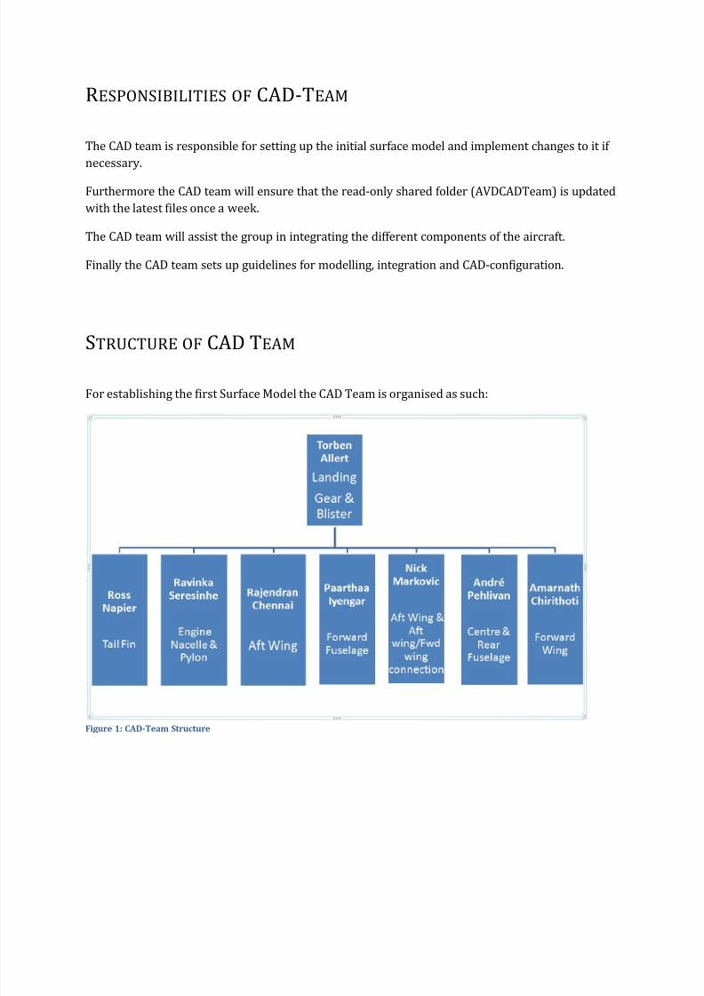
Figure 1: CAD-Team Structure ................................................................................................................................ 3
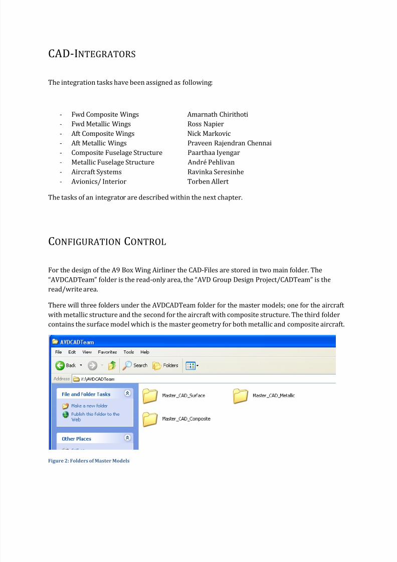
Figure 2: Folders of Master Models........................................................................................................................ 4
Figure 3: Location of CAD_Models Folder .............................................................................................................. 5
Figure 4: Example of Master Model ....................................................................................................................... 5
Figure 5: Responsibility of Integrators and Designers ............................................................................................ 6
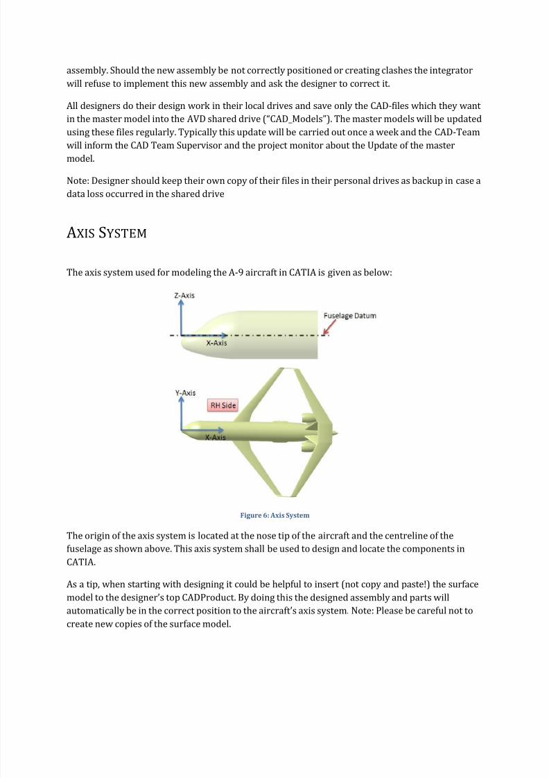
Figure 6: Axis System ............................................................................................................................................. 7
Figure 7: Modification Log inside CAD Files .......................................................................................................... 10
Figure 8: Example in Modification Log ................................................................................................................. 11
Figure 9: Structure of Modification Log ................................................................................................................ 11
Figure 10: Colour Coding ...................................................................................................................................... 12
Page 3
8/8/2019 CAD Policy A9
http://slidepdf.com/reader/full/cad-policy-a9 3/12
RESPONSIBILITIES OF CAD-TEAM
The CAD team is responsible for setting up the initial surface model and implement changes to it if
necessary.
Furthermore the CAD team will ensure that the read-only shared folder (AVDCADTeam) is updated
with the latest files once a week.
The CAD team will assist the group in integrating the different components of the aircraft.
Finally the CAD team sets up guidelines for modelling, integration and CAD-configuration.
STRUCTURE OF CAD TEAM
For establishing the first Surface Model the CAD Team is organised as such:
Page 4
8/8/2019 CAD Policy A9
http://slidepdf.com/reader/full/cad-policy-a9 4/12
CAD-INTEGRATORS
The integration tasks have been assigned as following:
- Fwd Composite Wings Amarnath Chirithoti
- Fwd Metallic Wings Ross Napier
- Aft Composite Wings Nick Markovic
- Aft Metallic Wings Praveen Rajendran Chennai
- Composite Fuselage Structure Paarthaa Iyengar
- Metallic Fuselage Structure André Pehlivan
- Aircraft Systems Ravinka Seresinhe
- Avionics/ Interior Torben Allert
The tasks of an integrator are described within the next chapter.
CONFIGURATION CONTROL
For the design of the A9 Box Wing Airliner the CAD-Files are stored in two main folder. The
“AVDCADTeam” folder is the read-only area, the “AVD Group Design Project/CADTeam” is the
read/write area.
There will three folders under the AVDCADTeam folder for the master models; one for the aircraft
Page 5
8/8/2019 CAD Policy A9
http://slidepdf.com/reader/full/cad-policy-a9 5/12
Only the CAD Team Members and the nominated staff have write-access to that folder. All otherAVD-participants have read-access.
The content of the Master-folders will be updated on a weekly basis. For the update of the CAD
models all AVD students shall work in their individual folders and copy their CAD-files into the AVD
Group Project folder (CAD_Models) and notify the CAD team about their updates.
Figure 3: Location of CAD_Models Folder
Within the “CAD_Models” Folder every team member will be provided with an individual folder.
MASTER MODELS The Master Model is a CADProduct-file with the main assemblies of the aircraft. In these main
assemblies (here e.g. “Fwd_Wing(C)”) the related top assemblies of the designers will be copied.
Page 6
8/8/2019 CAD Policy A9
http://slidepdf.com/reader/full/cad-policy-a9 6/12
RESPONSIBILITY FOR INTEGRATION
The CAD Team Integrators are responsible for the integration of their relevant components into the
master model on a top level basis, e.g. the CAD Integrator for the Fwd Wing will take care of all Fwd
wing related assemblies, the fuselage CAD integrator for all fuselage related assemblies etc.
Each designer is responsible to deliver to the CAD integrator an assembly in the correct axis system.
The CAD integrator will not do any work below the assembly level.
Page 7
8/8/2019 CAD Policy A9
http://slidepdf.com/reader/full/cad-policy-a9 7/12
assembly. Should the new assembly be not correctly positioned or creating clashes the integrator
will refuse to implement this new assembly and ask the designer to correct it.
All designers do their design work in their local drives and save only the CAD-files which they want
in the master model into the AVD shared drive (“CAD_Models”). The master models will be updated
using these files regularly. Typically this update will be carried out once a week and the CAD-Team
will inform the CAD Team Supervisor and the project monitor about the Update of the master
model.
Note: Designer should keep their own copy of their files in their personal drives as backup in case a
data loss occurred in the shared drive
AXIS SYSTEM
The axis system used for modeling the A-9 aircraft in CATIA is given as below:
Page 8
8/8/2019 CAD Policy A9
http://slidepdf.com/reader/full/cad-policy-a9 8/12
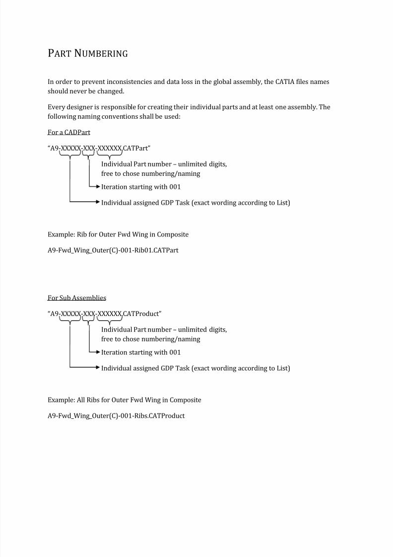
PART NUMBERING
In order to prevent inconsistencies and data loss in the global assembly, the CATIA files names
should never be changed.
Every designer is responsible for creating their individual parts and at least one assembly. The
following naming conventions shall be used:
For a CADPart
“A9-XXXXX-XXX-XXXXXX.CATPart”
Individual Part number – unlimited digits,
free to chose numbering/naming
Iteration starting with 001
Individual assigned GDP Task (exact wording according to List)
Example: Rib for Outer Fwd Wing in Composite
A9-Fwd_Wing_Outer(C)-001-Rib01.CATPart
For Sub Assemblies
Page 9
8/8/2019 CAD Policy A9
http://slidepdf.com/reader/full/cad-policy-a9 9/12
For the Top Assembly
The naming convention for the top assembly shall be as follows:
“A9-XXXXX-XXX.CATProduct”
Iteration starting with 001
Individual assigned GDP Task (exact wording according to List)
Example: Top Assembly for Outer Fwd Wing in Composite
A9-Fwd_Wing_Outer(C)-001.CATProduct “
DIMENSIONS AND SCALE
The 3D-Model shall be designed in full scale. Dimensions shall be in millimeters.
Page 10
8/8/2019 CAD Policy A9
http://slidepdf.com/reader/full/cad-policy-a9 10/12
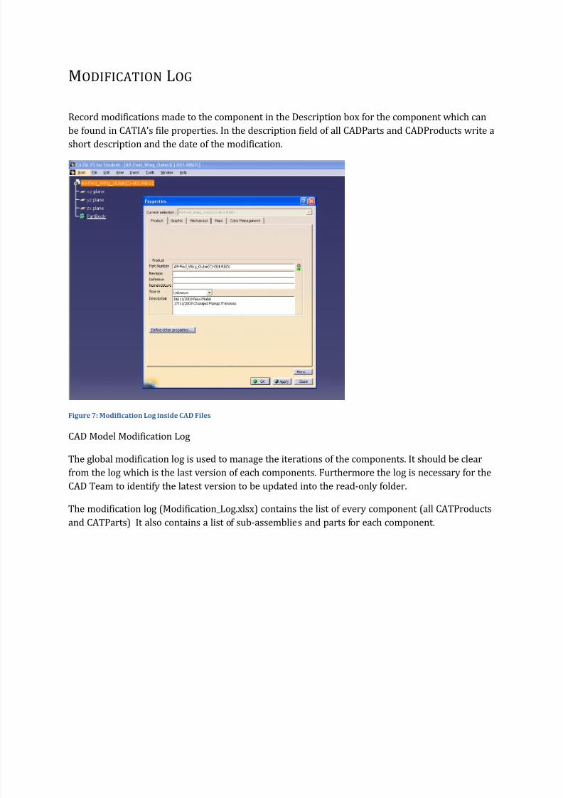
MODIFICATION LOG
Record modifications made to the component in the Description box for the component which can
be found in CATIA's file properties. In the description field of all CADParts and CADProducts write a
short description and the date of the modification.
Figure 7: Modification Log inside CAD Files
CAD M d l M difi i L
Page 11
8/8/2019 CAD Policy A9
http://slidepdf.com/reader/full/cad-policy-a9 11/12
Figure 8: Example in Modification Log
For each CATIA file created the following shall be specified:
Assembly-, Subassembly- and Part-names
Folder, where files are stored
Date of last modification,
Brief description of the modification,
Status (e.g. “new version waiting for update in the CAD model”, “updated”…).
There are 8 different sheets in this Excel-Spreadsheet, each for one CAD-Integrator. Designer must
take care to put their data in the correct sheet. Which components belong to each CAD-Integrator is
shown in an additional sheet (Allocation).
Page 12
8/8/2019 CAD Policy A9
http://slidepdf.com/reader/full/cad-policy-a9 12/12
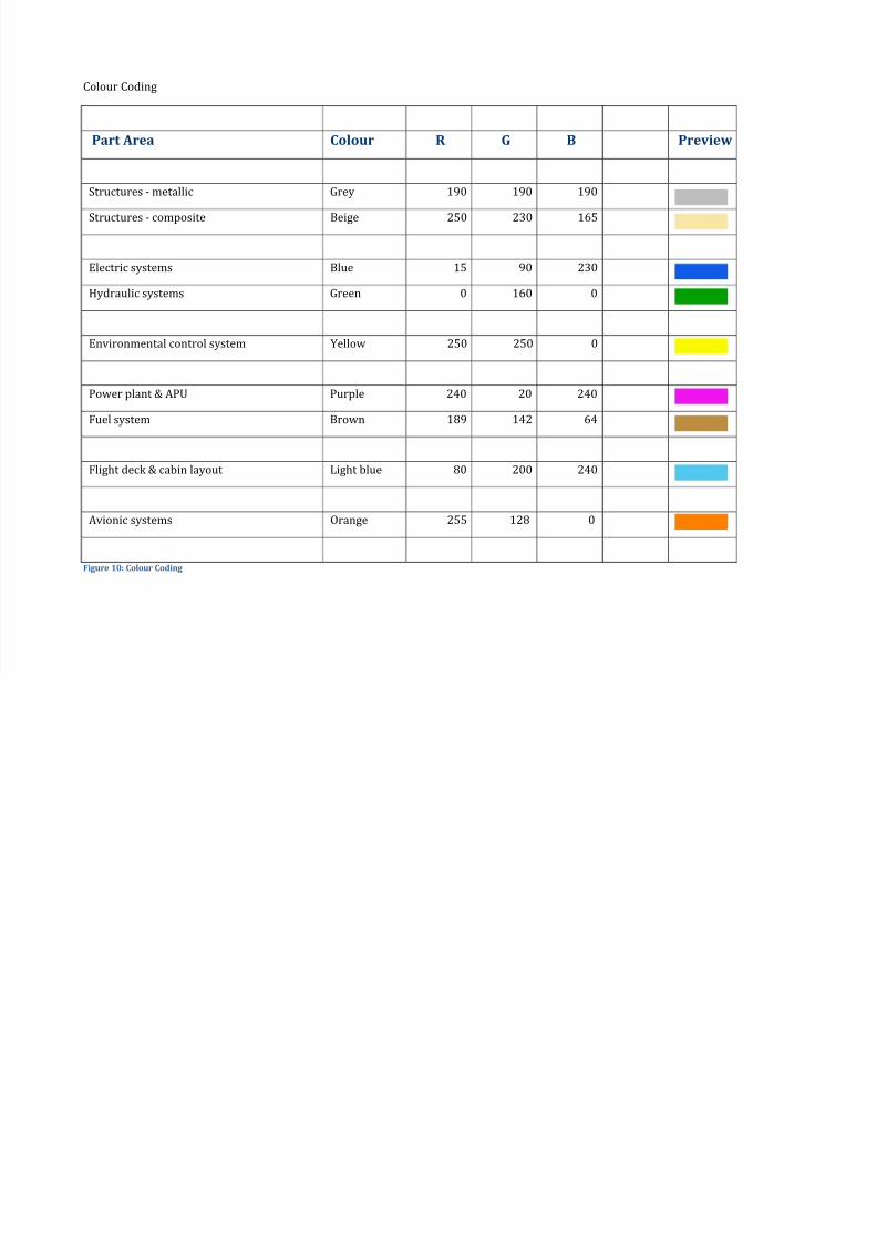
Colour Coding
Part Area Colour R G B Preview
Structures - metallic Grey 190 190 190
Structures - composite Beige 250 230 165
Electric systems Blue 15 90 230
Hydraulic systems Green 0 160 0
Environmental control system Yellow 250 250 0
Power plant & APU Purple 240 20 240
Fuel system Brown 189 142 64
Flight deck & cabin layout Light blue 80 200 240
Avionic systems Orange 255 128 0
Figure 10: Colour Coding