68
CADvent plugin for MagiCAD for version 1.8

CADvent plugin for MagiCAD
for version 1.8
2/68
lindab | we simplify construction
Table of Content Manual for Lindab CADvent plugin for MagiCAD ................................................................... 4
General Information ........................................................................................................... 4
Installation and activation ................................................................................................... 4
Installation requirements ................................................................................................ 4
Installation process ......................................................................................................... 5
List of functions and User Interface .................................................................................... 8
Graphical User Interface for CADvent plugin with MagiCAD ........................................... 8
Ribbon palette ................................................................................................................ 8
Right-click menu ............................................................................................................. 8
Graphical User Interface for CADvent plugin without MagiCAD ...................................... 8
List of functions .............................................................................................................. 9
Functionality of the Lindab CADvent plugin ..........................................................................11
Import Duct Series ............................................................................................................11
Update Properties .............................................................................................................13
Manage Ducts...................................................................................................................14
Set Length ........................................................................................................................15
Optimize Fittings ...............................................................................................................17
Model Checker..................................................................................................................19
Edit Forced Products .....................................................................................................20
Piece Labels .....................................................................................................................21
Group by: ......................................................................................................................22
Numbering method: .......................................................................................................23
Piece label format: .........................................................................................................24
Edit: ...............................................................................................................................24
Translations ...................................................................................................................26
Part categories ..............................................................................................................26
Assign Piece Labels to MagiCAD UserVar2 ..................................................................26
Face Text ......................................................................................................................27
Next start number ..........................................................................................................27
Add New .......................................................................................................................27
Modify Piece labels ...........................................................................................................28
Properties ......................................................................................................................29
Manually changes of the Piece label. ............................................................................29
3/68
lindab | we simplify construction
Changes of the system ..................................................................................................30
Bill of Materials .................................................................................................................32
Cut all ducts to drawing length.......................................................................................32
Lengths on BoM ............................................................................................................34
Cut all ducts to drawing length.......................................................................................36
Webshop Upload ..............................................................................................................36
Lindab Webshop ...............................................................................................................40
Add Space ........................................................................................................................48
lindQST Upload ................................................................................................................50
Leakage and Leakage Area Calculation ...........................................................................53
Leakage classes ...........................................................................................................54
Definition of the leakage classes ...................................................................................54
Leakage Area Calculation: ............................................................................................55
Leakage plug .................................................................................................................57
Special Components .....................................................................................................57
InCapsa Design Tool – Draw a wall panel system. ...........................................................58
InCapsa Design Tool – Draw a Free Panel system. ..........................................................62
Create Bill of Material for InCapsa Systems ......................................................................63
InCapsa Design Tool – Draw the ventilation ductwork with MagiCAD ...............................65
About ................................................................................................................................68
4/68
lindab | we simplify construction
Manual for Lindab CADvent plugin for MagiCAD
General Information
The Lindab CADvent plugin is developed to support CADvent advanced production orientated features on top of MagiCAD using the production orientated objects in MagiCAD.
Additional to this, the plugin offers features that are also available on computers without MagiCAD.
Please read more about this in ‘List of functions and User Interface’
Installation and activation
The latest version of the CADvent plugin can be downloaded from http://itsolution.lindab.com/downloads/cadventplugin/cadventplugin.exe
Installation requirements
The CADvent plugin supports AutoCAD 2010 to 2015 on 32 or 64 bit computer.
For the extended version the plug in requires MagiCAD 2013.11 which runs on AutoCAD 2010 to AutoCAD 2014 or MagiCAD 2014.4 for AutoCAD 2010 to 2015 on 32 or 64 bit computers. The plugin supports Windows 7 and Windows 8.
NOTE: You need to have local administrator rights to install the plugin on your computer.

5/68
lindab | we simplify construction
Installation process
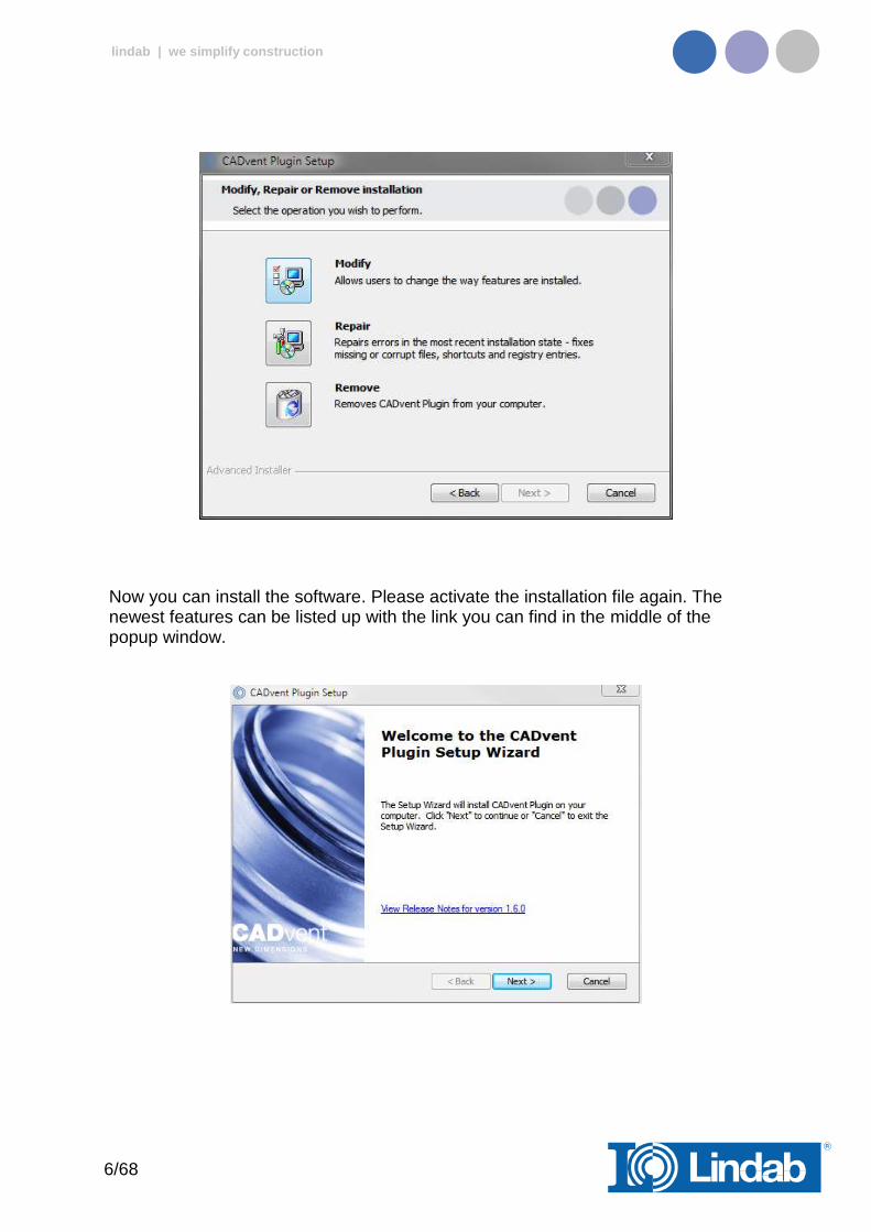
Download the installation file and save it on your computer for later installation or install it by pushing the “Run” button. If you have an earlier version of CADvent plugin installed the installation process first likes to uninstall the current version of the plugin.
Press Next and in the following Window Remove to uninstall the current version.
6/68
lindab | we simplify construction
Now you can install the software. Please activate the installation file again. The newest features can be listed up with the link you can find in the middle of the popup window.
7/68
lindab | we simplify construction
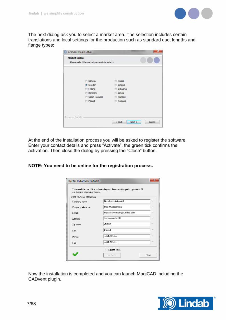
The next dialog ask you to select a market area. The selection includes certain translations and local settings for the production such as standard duct lengths and flange types:
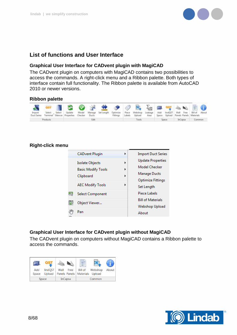
At the end of the installation process you will be asked to register the software. Enter your contact details and press “Activate”, the green tick confirms the activation. Then close the dialog by pressing the “Close” button.
NOTE: You need to be online for the registration process.
Now the installation is completed and you can launch MagiCAD including the CADvent plugin.
Max Mustermann
8/68
lindab | we simplify construction
List of functions and User Interface
Graphical User Interface for CADvent plugin with MagiCAD
The CADvent plugin on computers with MagiCAD contains two possibilities to access the commands. A right-click menu and a Ribbon palette. Both types of interface contain full functionality. The Ribbon palette is available from AutoCAD 2010 or newer versions.
Ribbon palette
Right-click menu
Graphical User Interface for CADvent plugin without MagiCAD
The CADvent plugin on computers without MagiCAD contains a Ribbon palette to access the commands.
9/68
lindab | we simplify construction
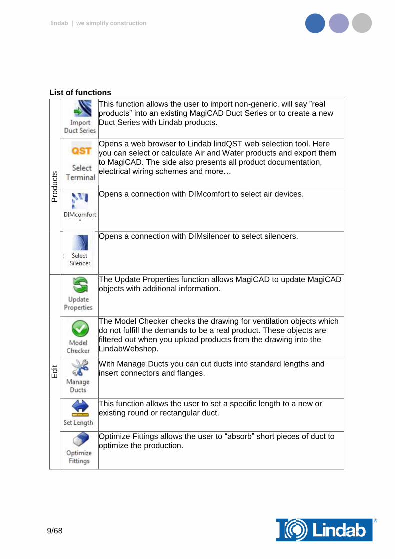
List of functions
Pro
du
cts
This function allows the user to import non-generic, will say ”real products” into an existing MagiCAD Duct Series or to create a new Duct Series with Lindab products.
Opens a web browser to Lindab lindQST web selection tool. Here you can select or calculate Air and Water products and export them to MagiCAD. The side also presents all product documentation, electrical wiring schemes and more…
Opens a connection with DIMcomfort to select air devices.
Opens a connection with DIMsilencer to select silencers.
Ed
it
The Update Properties function allows MagiCAD to update MagiCAD objects with additional information.
The Model Checker checks the drawing for ventilation objects which do not fulfill the demands to be a real product. These objects are filtered out when you upload products from the drawing into the LindabWebshop.
With Manage Ducts you can cut ducts into standard lengths and insert connectors and flanges.
This function allows the user to set a specific length to a new or existing round or rectangular duct.
Optimize Fittings allows the user to “absorb” short pieces of duct to optimize the production.
10/68
lindab | we simplify construction
To
ols
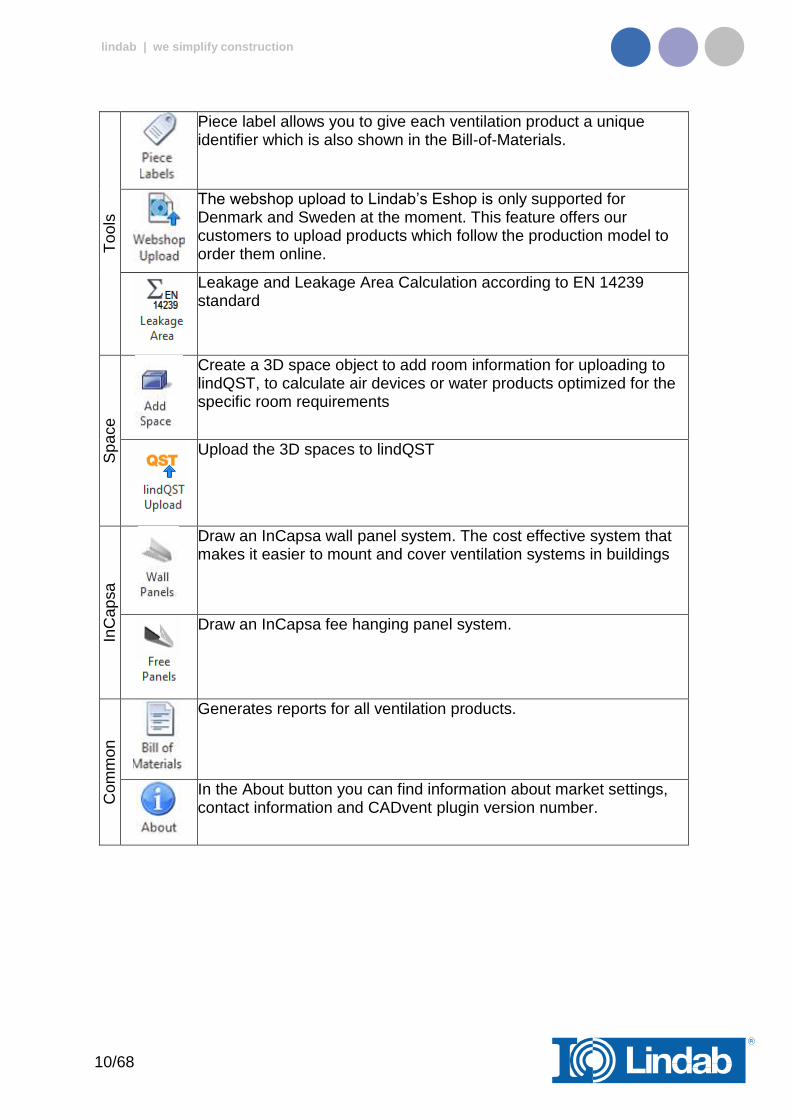
Piece label allows you to give each ventilation product a unique identifier which is also shown in the Bill-of-Materials.
The webshop upload to Lindab’s Eshop is only supported for Denmark and Sweden at the moment. This feature offers our customers to upload products which follow the production model to order them online.
Leakage and Leakage Area Calculation according to EN 14239 standard
Sp
ace
Create a 3D space object to add room information for uploading to lindQST, to calculate air devices or water products optimized for the specific room requirements
Upload the 3D spaces to lindQST
InC
ap
sa
Draw an InCapsa wall panel system. The cost effective system that makes it easier to mount and cover ventilation systems in buildings
Draw an InCapsa fee hanging panel system.
Com
mo
n
Generates reports for all ventilation products.
In the About button you can find information about market settings, contact information and CADvent plugin version number.
11/68
lindab | we simplify construction
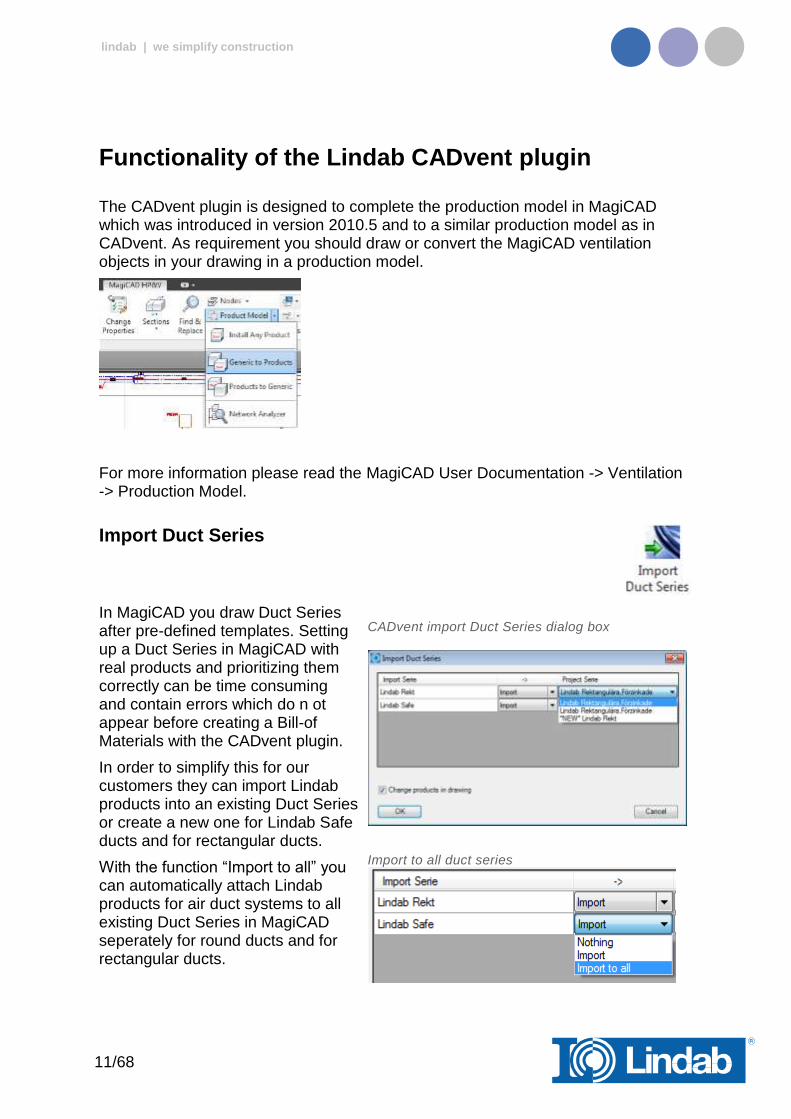
Functionality of the Lindab CADvent plugin
The CADvent plugin is designed to complete the production model in MagiCAD which was introduced in version 2010.5 and to a similar production model as in CADvent. As requirement you should draw or convert the MagiCAD ventilation objects in your drawing in a production model.
For more information please read the MagiCAD User Documentation -> Ventilation -> Production Model.
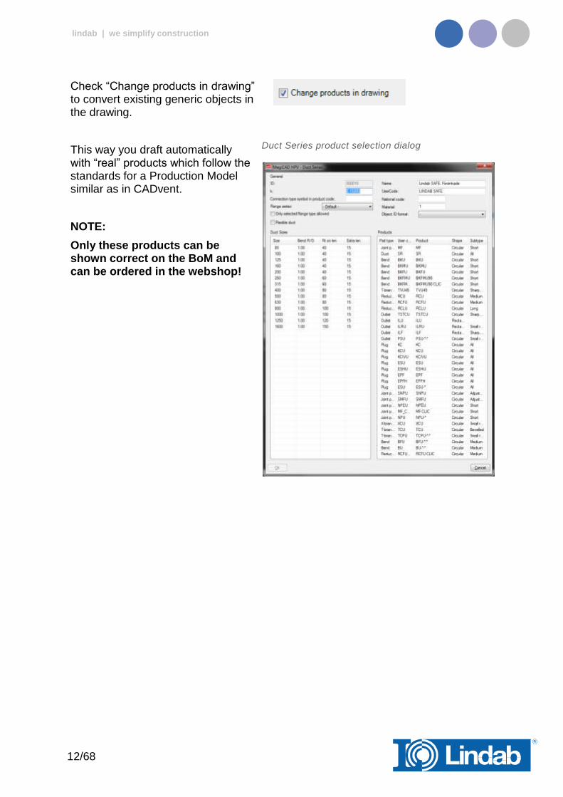
Import Duct Series
In MagiCAD you draw Duct Series after pre-defined templates. Setting up a Duct Series in MagiCAD with real products and prioritizing them correctly can be time consuming and contain errors which do n ot appear before creating a Bill-of Materials with the CADvent plugin.
In order to simplify this for our customers they can import Lindab products into an existing Duct Series or create a new one for Lindab Safe ducts and for rectangular ducts.
With the function “Import to all” you can automatically attach Lindab products for air duct systems to all existing Duct Series in MagiCAD seperately for round ducts and for rectangular ducts.
CADvent import Duct Series dialog box
Import to all duct series
12/68
lindab | we simplify construction
Check “Change products in drawing” to convert existing generic objects in the drawing.
This way you draft automatically with “real” products which follow the standards for a Production Model similar as in CADvent.
NOTE:
Only these products can be shown correct on the BoM and can be ordered in the webshop!
Duct Series product selection dialog

13/68
lindab | we simplify construction
Update Properties
The Update Properties command should be used after you have drawn your MagiCAD production model objects to add information.
When you are finished drafting or to update information in-between just push the Update Properties button, select a MagiCAD ventilation object and open the AutoCAD Properties as shown to the left.
Parameters for Update Properties:
- Custom String: Allows you to set manually a text string which is shown in the Bill-of-materials.
- Material: Sets a material which is used in the BoM and necessary for product upload to the LindabEshop. Alternatively the material stated in the MagiCAD Duct Series can be used.
- Piece label: Gives a unique ID to each product.
- Piece label lock: Locks the ID you set manually. The ID will not get overwritten by the automatic Piece label function in the CADvent plugin.
- Order Length: Give a rectangular duct another length value manually to be able to cut the duct on site.
- Flange Index: Position of flange on an object. The Index is also marked per product in the drawing. By default “All” are selected and the marker is deactivated.
- Flange type: Select a standard flange type according to your market settings.
- Flange attachment: Set a flange type “Normal” or “Loose” if you want to be able to cut the duct on site.
- Flange lock: Lock the setting of this flange, then the CADvent plugin will not change the flange type or attachment using the Manage Ducts function
CADvent plugin Properties
Flange Index mark in drawing
14/68
lindab | we simplify construction
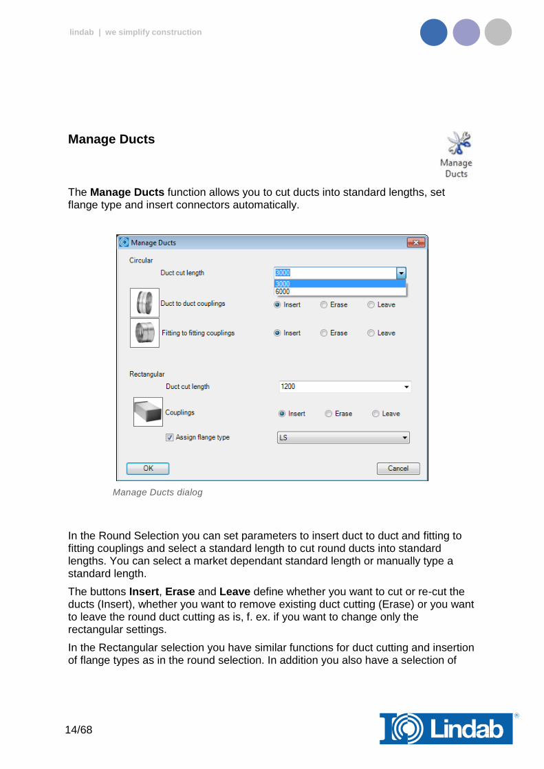
Manage Ducts
The Manage Ducts function allows you to cut ducts into standard lengths, set flange type and insert connectors automatically.
Manage Ducts dialog
In the Round Selection you can set parameters to insert duct to duct and fitting to fitting couplings and select a standard length to cut round ducts into standard lengths. You can select a market dependant standard length or manually type a standard length.
The buttons Insert, Erase and Leave define whether you want to cut or re-cut the ducts (Insert), whether you want to remove existing duct cutting (Erase) or you want to leave the round duct cutting as is, f. ex. if you want to change only the rectangular settings.
In the Rectangular selection you have similar functions for duct cutting and insertion of flange types as in the round selection. In addition you also have a selection of
15/68
lindab | we simplify construction
market specific flange types and a check button to assign the selected flange type to the rectangular ductwork.
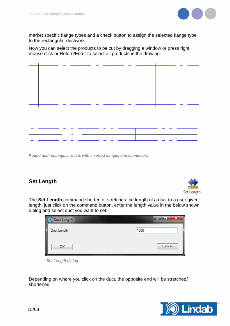
Now you can select the products to be cut by dragging a window or press right mouse click or Return/Enter to select all products in the drawing.
Round and rectangular ducts with inserted flanges and connectors
Set Length
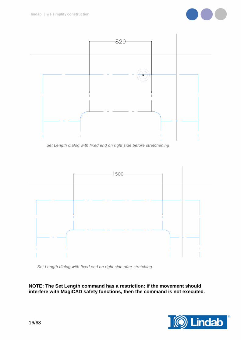
The Set Length command shorten or stretches the length of a duct to a user given length, just click on the command button, enter the length value in the below shown dialog and select duct you want to set:
Set Length dialog
Depending on where you click on the duct, the opposite end will be stretched/ shortened:
16/68
lindab | we simplify construction
Set Length dialog with fixed end on right side before stretchening
Set Length dialog with fixed end on right side after stretching
NOTE: The Set Length command has a restriction: if the movement should interfere with MagiCAD safety functions, then the command is not executed.
17/68
lindab | we simplify construction
Optimize Fittings
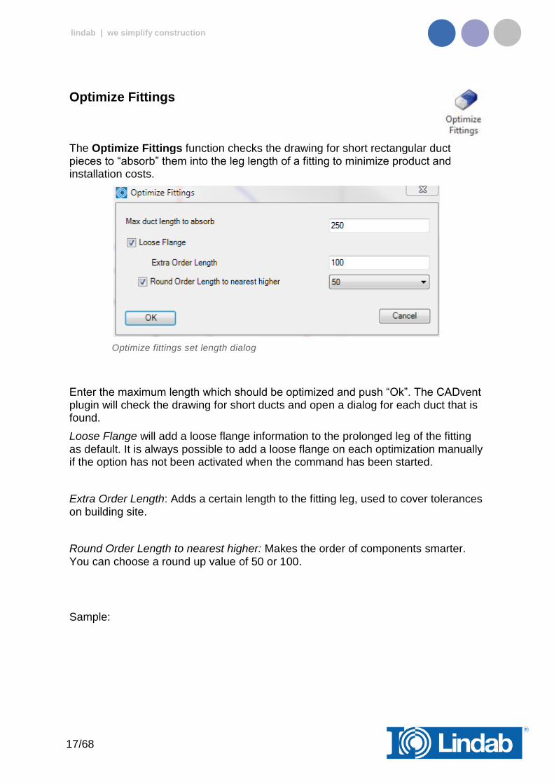
The Optimize Fittings function checks the drawing for short rectangular duct pieces to “absorb” them into the leg length of a fitting to minimize product and installation costs.
Optimize fittings set length dialog
Enter the maximum length which should be optimized and push “Ok”. The CADvent plugin will check the drawing for short ducts and open a dialog for each duct that is found.
Loose Flange will add a loose flange information to the prolonged leg of the fitting as default. It is always possible to add a loose flange on each optimization manually if the option has not been activated when the command has been started.
Extra Order Length: Adds a certain length to the fitting leg, used to cover tolerances on building site.
Round Order Length to nearest higher: Makes the order of components smarter. You can choose a round up value of 50 or 100.
Sample:

18/68
lindab | we simplify construction
Absorb short pieces of duct to fitting
The duct and fitting which shall be optimized will be shown with dashed outlines. Press “Accept” to execute the optimization or “Other Side” (only possible when the duct is between two fittings as shown above) to switch the optimization to the other side.
The current fitting is made with a 25mm standard leg length. After optimization, following leg length will be activated at the fitting:
Not activated Loose Flange option: 239mm (= 214mm + 25mm)
Activated Loose Flange option and extra order length of 100mm: 339mm (= 239 + 100mm) Round order Length to nearest higher 50mm: 350mm Round order Length to nearest higher 100mm: 400mm
19/68
lindab | we simplify construction
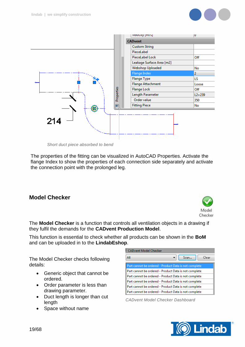
Short duct piece absorbed to bend
The properties of the fitting can be visualized in AutoCAD Properties. Activate the flange Index to show the properties of each connection side separately and activate the connection point with the prolonged leg.
Model Checker
The Model Checker is a function that controls all ventilation objects in a drawing if they fulfil the demands for the CADvent Production Model.
This function is essential to check whether all products can be shown in the BoM and can be uploaded in to the LindabEshop.
The Model Checker checks following details:
Generic object that cannot be ordered.
Order parameter is less than drawing parameter.
Duct length is longer than cut length
Space without name
CADvent Model Checker Dashboard

20/68
lindab | we simplify construction
Push the Model Check button to open an AutoCAD Dashboard on the side of your screen and push the “Scan” button to check the drawing for products which can’t be ordered.
Click on one of the parts to move the object into scope and mark it.
Non production model object marked with Model Checker
The marking can be shut off in the Dashboard – Options...
Model Checker Dashboard with marker function
Edit Forced Products
Activate this option if you like to force products to be another type of product. The image below shows a bend with a 3° angle, which is a not existing product. On building side this can be handled inside the tolerances of a duct connector NPU.
Activate Edit Forced Products opens an edit column in the model checker table.
21/68
lindab | we simplify construction
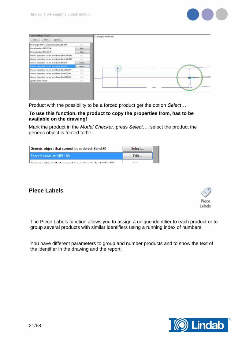
Product with the possibility to be a forced product get the option Select…
To use this function, the product to copy the properties from, has to be available on the drawing!
Mark the product in the Model Checker, press Select…, select the product the generic object is forced to be.
Piece Labels
The Piece Labels function allows you to assign a unique identifier to each product or to group several products with similar identifiers using a running index of numbers.
You have different parameters to group and number products and to show the text of the identifier in the drawing and the report:
22/68
lindab | we simplify construction
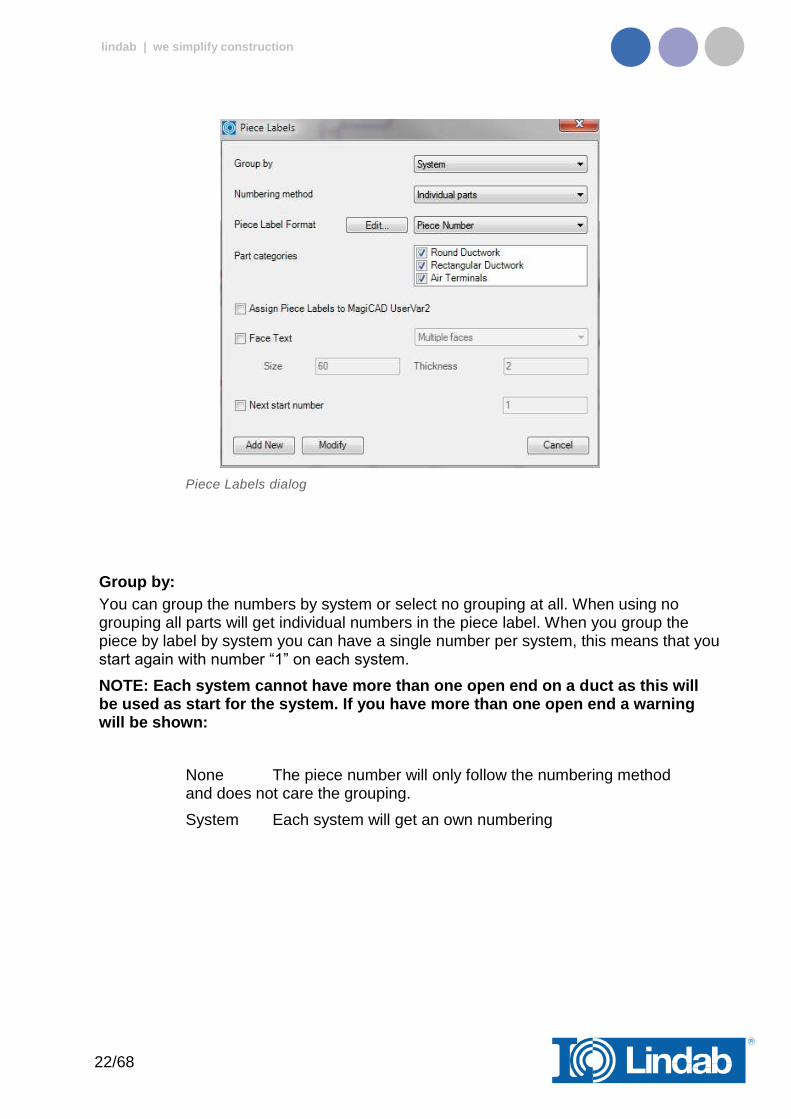
Piece Labels dialog
Group by:
You can group the numbers by system or select no grouping at all. When using no grouping all parts will get individual numbers in the piece label. When you group the piece by label by system you can have a single number per system, this means that you start again with number “1” on each system.
NOTE: Each system cannot have more than one open end on a duct as this will be used as start for the system. If you have more than one open end a warning will be shown:
None The piece number will only follow the numbering method and does not care the grouping.
System Each system will get an own numbering
23/68
lindab | we simplify construction
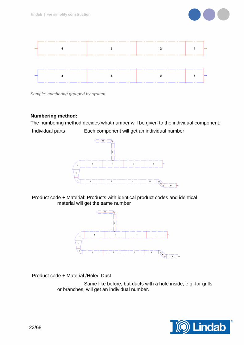
Sample: numbering grouped by system
Numbering method:
The numbering method decides what number will be given to the individual component:
Individual parts Each component will get an individual number
Product code + Material: Products with identical product codes and identical material will get the same number
Product code + Material /Holed Duct
Same like before, but ducts with a hole inside, e.g. for grills or branches, will get an individual number.
24/68
lindab | we simplify construction
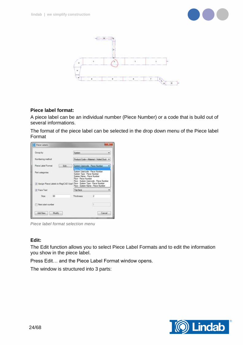
Piece label format:
A piece label can be an individual number (Piece Number) or a code that is build out of several informations.
The format of the piece label can be selected in the drop down menu of the Piece label Format
Piece label format selection menu
Edit:
The Edit function allows you to select Piece Label Formats and to edit the information you show in the piece label.
Press Edit… and the Piece Label Format window opens.
The window is structured into 3 parts:
25/68
lindab | we simplify construction
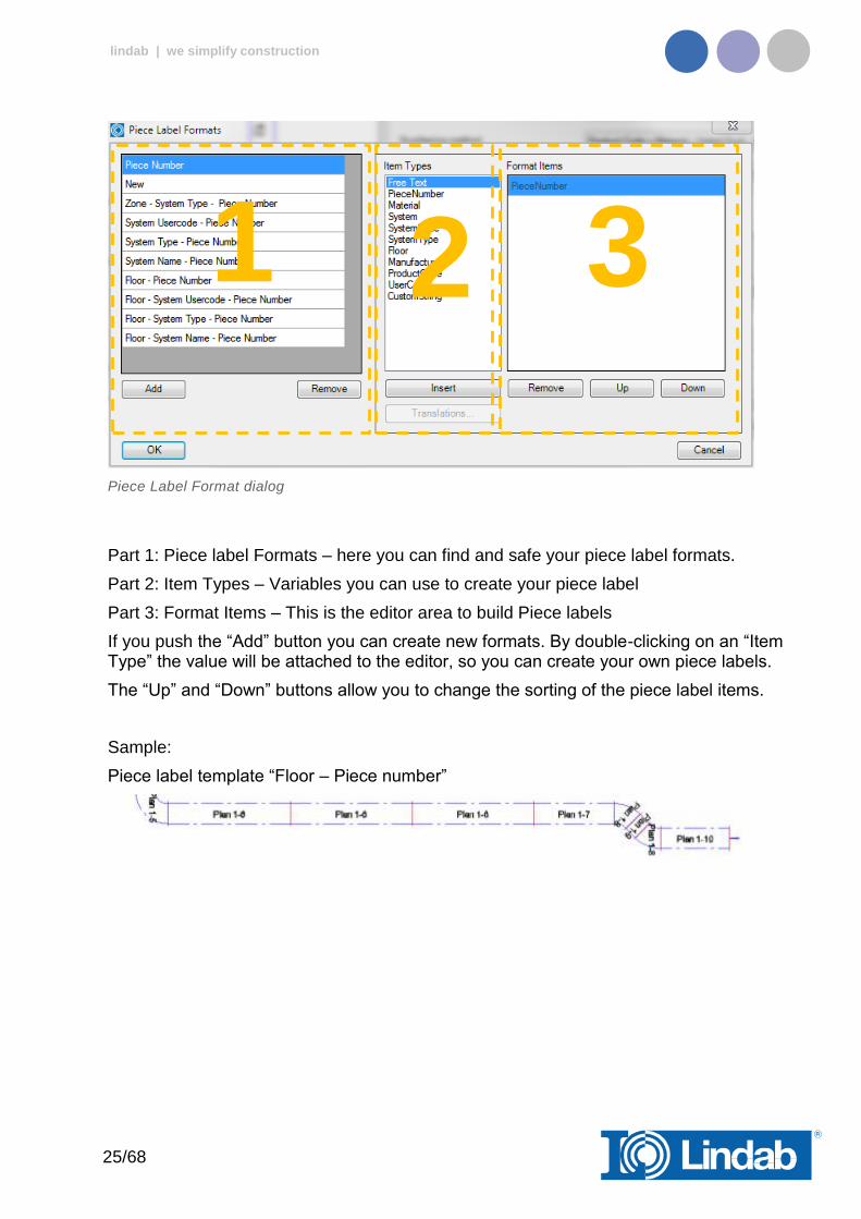
Piece Label Format dialog
Part 1: Piece label Formats – here you can find and safe your piece label formats.
Part 2: Item Types – Variables you can use to create your piece label
Part 3: Format Items – This is the editor area to build Piece labels
If you push the “Add” button you can create new formats. By double-clicking on an “Item Type” the value will be attached to the editor, so you can create your own piece labels.
The “Up” and “Down” buttons allow you to change the sorting of the piece label items.
Sample:
Piece label template “Floor – Piece number”
1 2 3
26/68
lindab | we simplify construction
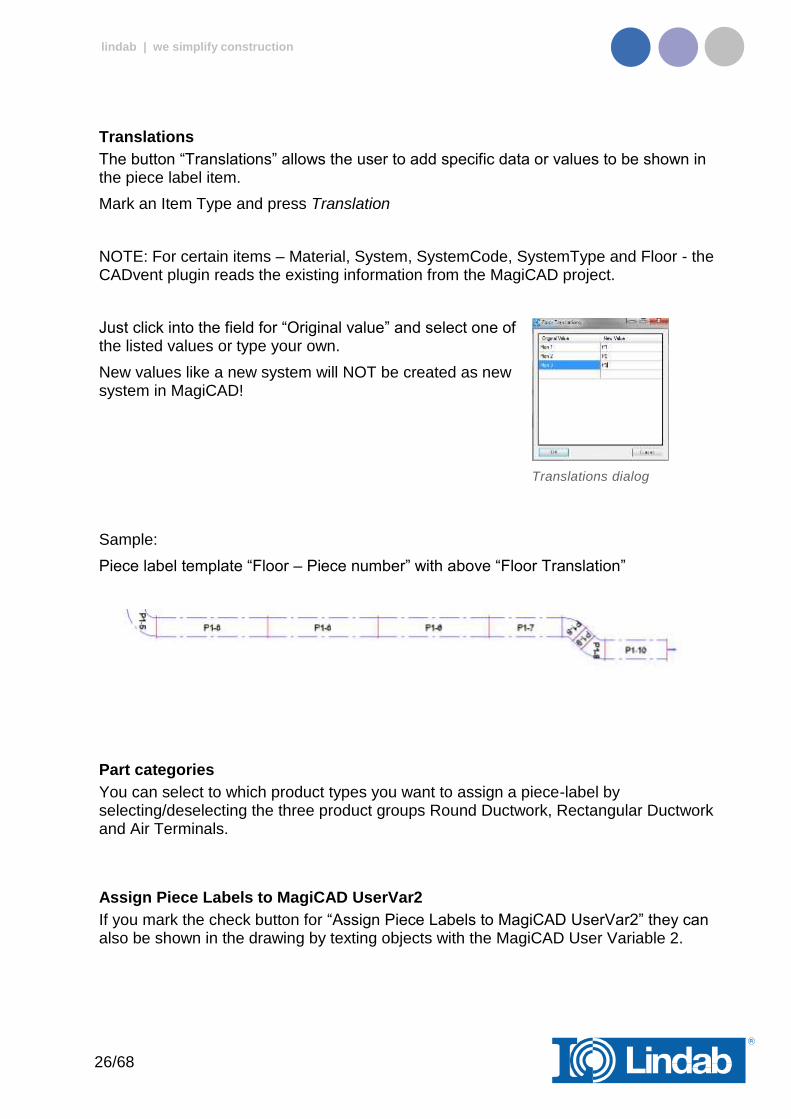
Translations
The button “Translations” allows the user to add specific data or values to be shown in the piece label item.
Mark an Item Type and press Translation
NOTE: For certain items – Material, System, SystemCode, SystemType and Floor - the CADvent plugin reads the existing information from the MagiCAD project.
Just click into the field for “Original value” and select one of the listed values or type your own.
New values like a new system will NOT be created as new system in MagiCAD!
Translations dialog
Sample:
Piece label template “Floor – Piece number” with above “Floor Translation”
Part categories
You can select to which product types you want to assign a piece-label by selecting/deselecting the three product groups Round Ductwork, Rectangular Ductwork and Air Terminals.
Assign Piece Labels to MagiCAD UserVar2
If you mark the check button for “Assign Piece Labels to MagiCAD UserVar2” they can also be shown in the drawing by texting objects with the MagiCAD User Variable 2.

27/68
lindab | we simplify construction
Face Text
The Piece labels can be visualized in the drawing with a Face Text. You can chose between two options:
Top Face Required for 2D and wireframe visualizations
Multiple Faces Required for 3D shaded visualization
2D Wireframe visualization with Top Face Piece labels and conceptual visualization with Multiple Faces labels
Next start number
Next start number allows the user to select a self-defined start number for the numbering.
Note: The given number is used as minimum number. Does the given number already exist in the drawing, CADvent will choose the next free number!
Add New
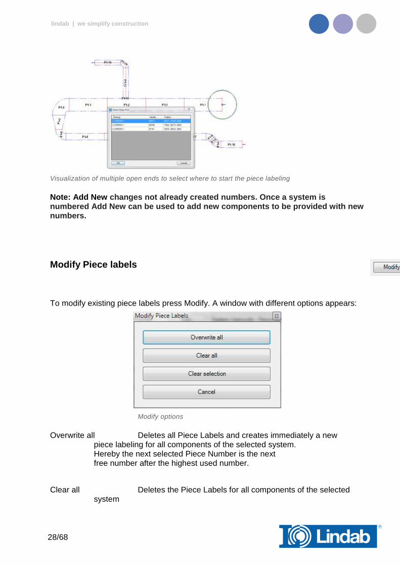
Press the Add New button to start the piece label process. Click on a part of the system you like to label. If the system you like to label contains more than one open end, all open ends will be visualized in a table and marked with a circle. Select the open end where the labeling shall start.
28/68
lindab | we simplify construction
Visualization of multiple open ends to select where to start the piece labeling
Note: Add New changes not already created numbers. Once a system is numbered Add New can be used to add new components to be provided with new numbers.
Modify Piece labels
To modify existing piece labels press Modify. A window with different options appears:
Modify options
Overwrite all Deletes all Piece Labels and creates immediately a new piece labeling for all components of the selected system. Hereby the next selected Piece Number is the next free number after the highest used number.
Clear all Deletes the Piece Labels for all components of the selected system
29/68
lindab | we simplify construction
Clear selection Deletes the Piece Label only for selected components
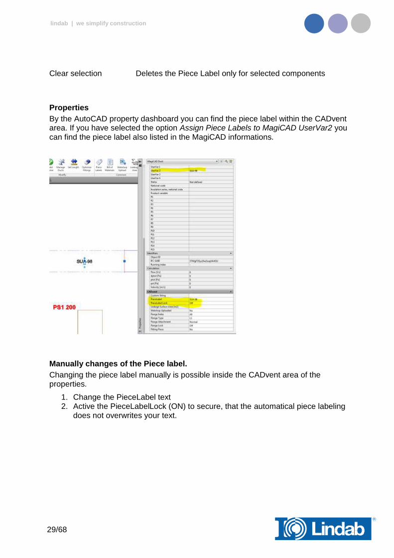
Properties
By the AutoCAD property dashboard you can find the piece label within the CADvent area. If you have selected the option Assign Piece Labels to MagiCAD UserVar2 you can find the piece label also listed in the MagiCAD informations.
Manually changes of the Piece label.
Changing the piece label manually is possible inside the CADvent area of the properties.
1. Change the PieceLabel text 2. Active the PieceLabelLock (ON) to secure, that the automatical piece labeling
does not overwrites your text.

30/68
lindab | we simplify construction
3. Activate the CADvent piece label function and press Add New
This will change the visualized piece label and writes the manual given text to the MagiCAD UserVar 2
Changes of the system
Changes in the system need almost an update of the piece labels. As soon as order processes have already been started, changes of existing piece labels are taboo.
How to handle changes in the system:
Sample:
Below you can see a duct system with final piece label
After the order process has already been started the middle duct shall be set a few cm down, to give some space for heating pipes. As long as the same ducts are used, the piece label will not change, not even when the duct length has been changed.
31/68
lindab | we simplify construction
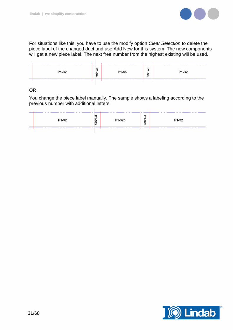
For situations like this, you have to use the modify option Clear Selection to delete the piece label of the changed duct and use Add New for this system. The new components will get a new piece label. The next free number from the highest existing will be used.
OR
You change the piece label manually. The sample shows a labeling according to the previous number with additional letters.

32/68
lindab | we simplify construction
Bill of Materials
Push the button for Bill of Materials and drag a window over the Lindab products which shall be included on the BoM reports.
Two reports will appear: One report for the rectangular ducts and another report for circular ducts and technical components.
You can decide whether you want to show the piece-label on the report or if you want to suppress it by checking/unchecking the show piece-label function
Dialog for Bill-of-Materials
Find more info about “Separate InCapsa Systems” at “Create Bill of Material for InCapsa Systems”
Cut all ducts to drawing length
Without active checkbox the BoM will summarize all round ducts into standard lengths, set in the Manage Ducts command, except the drawn ducts will have a length of 3000 or 6000mm (Lindab Standard)
33/68
lindab | we simplify construction
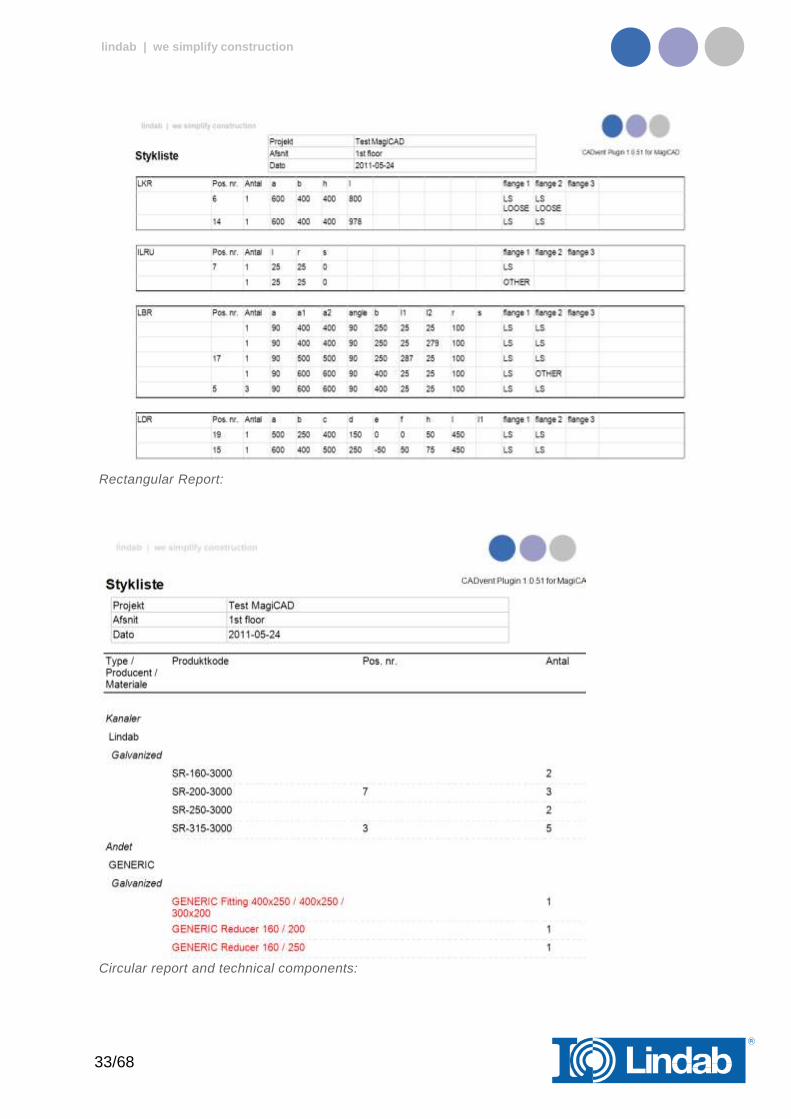
Rectangular Report:
Circular report and technical components:

34/68
lindab | we simplify construction
Products which are not following the rules for a production model are listed with their connection information and type as generic objects.
The reports can be exported as PDF or to Excel.
Lengths on BoM
Without active checkbox the BoM will summarize all round ducts into standard lengths, set in the Manage Ducts command, except the drawn ducts will have a length of 3000 or 6000mm (Lindab Standard)
Sample 1:
1. Draw a 22m long duct 2. Activate the duct cut length to 2500mm, without placing connectors.
3. Result on Bill of Materials.
The material list summarizes all ducts per size and divides the total length into 2500mm pieces.
Sample 2:
1. Do the same process like above and activate a Duct cut length of 3000mm 2. Insert connectors. 3. Change the Duct cut length to 2500 mm without inserting any connector.
35/68
lindab | we simplify construction
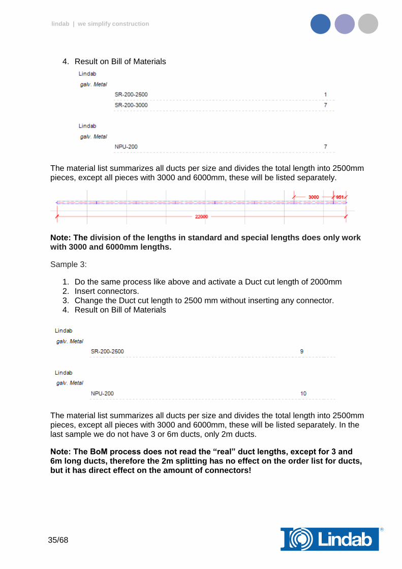
4. Result on Bill of Materials
The material list summarizes all ducts per size and divides the total length into 2500mm pieces, except all pieces with 3000 and 6000mm, these will be listed separately.
Note: The division of the lengths in standard and special lengths does only work with 3000 and 6000mm lengths.
Sample 3:
1. Do the same process like above and activate a Duct cut length of 2000mm 2. Insert connectors. 3. Change the Duct cut length to 2500 mm without inserting any connector. 4. Result on Bill of Materials
The material list summarizes all ducts per size and divides the total length into 2500mm pieces, except all pieces with 3000 and 6000mm, these will be listed separately. In the last sample we do not have 3 or 6m ducts, only 2m ducts.
Note: The BoM process does not read the “real” duct lengths, except for 3 and 6m long ducts, therefore the 2m splitting has no effect on the order list for ducts, but it has direct effect on the amount of connectors!
36/68
lindab | we simplify construction
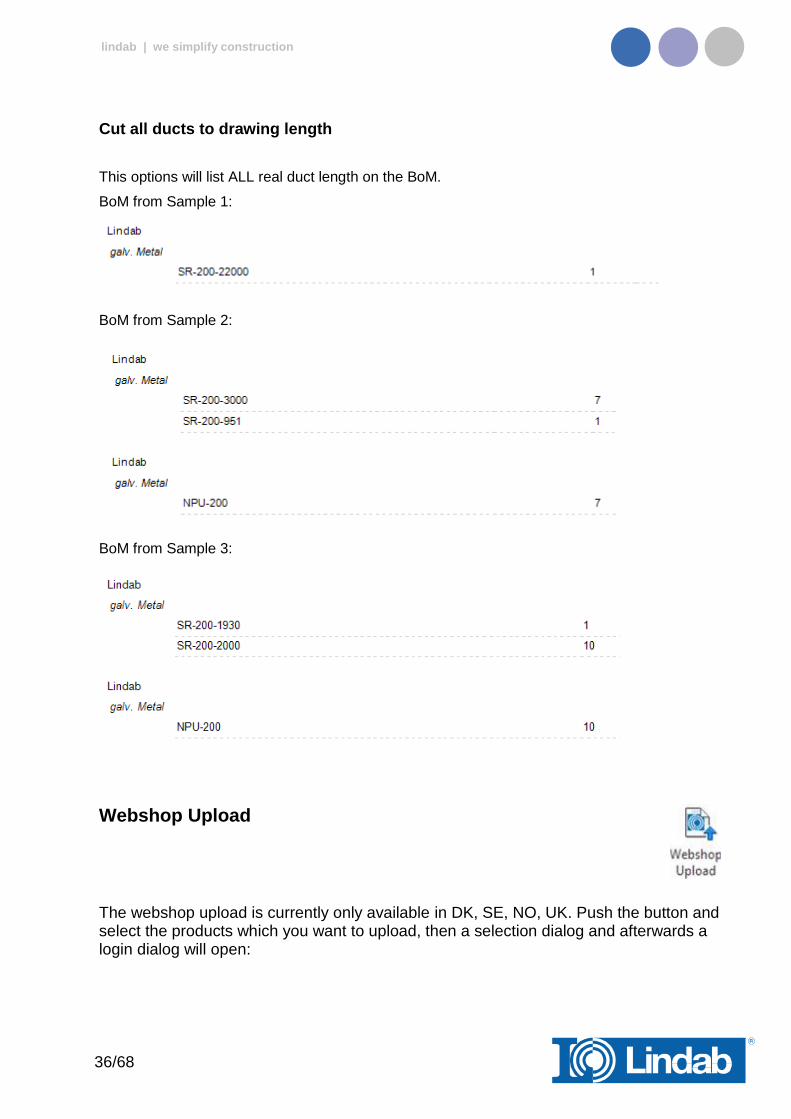
Cut all ducts to drawing length
This options will list ALL real duct length on the BoM.
BoM from Sample 1:
BoM from Sample 2:
BoM from Sample 3:
Webshop Upload
The webshop upload is currently only available in DK, SE, NO, UK. Push the button and select the products which you want to upload, then a selection dialog and afterwards a login dialog will open:
37/68
lindab | we simplify construction
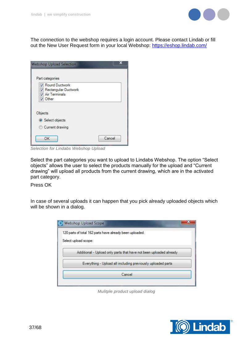
The connection to the webshop requires a login account. Please contact Lindab or fill out the New User Request form in your local Webshop: https://eshop.lindab.com/
Selection for Lindabs Webshop Upload
Select the part categories you want to upload to Lindabs Webshop. The option “Select objects” allows the user to select the products manually for the upload and “Current drawing” will upload all products from the current drawing, which are in the activated part category.
Press OK
In case of several uploads it can happen that you pick already uploaded objects which will be shown in a dialog.
Mulitple product upload dialog
38/68
lindab | we simplify construction
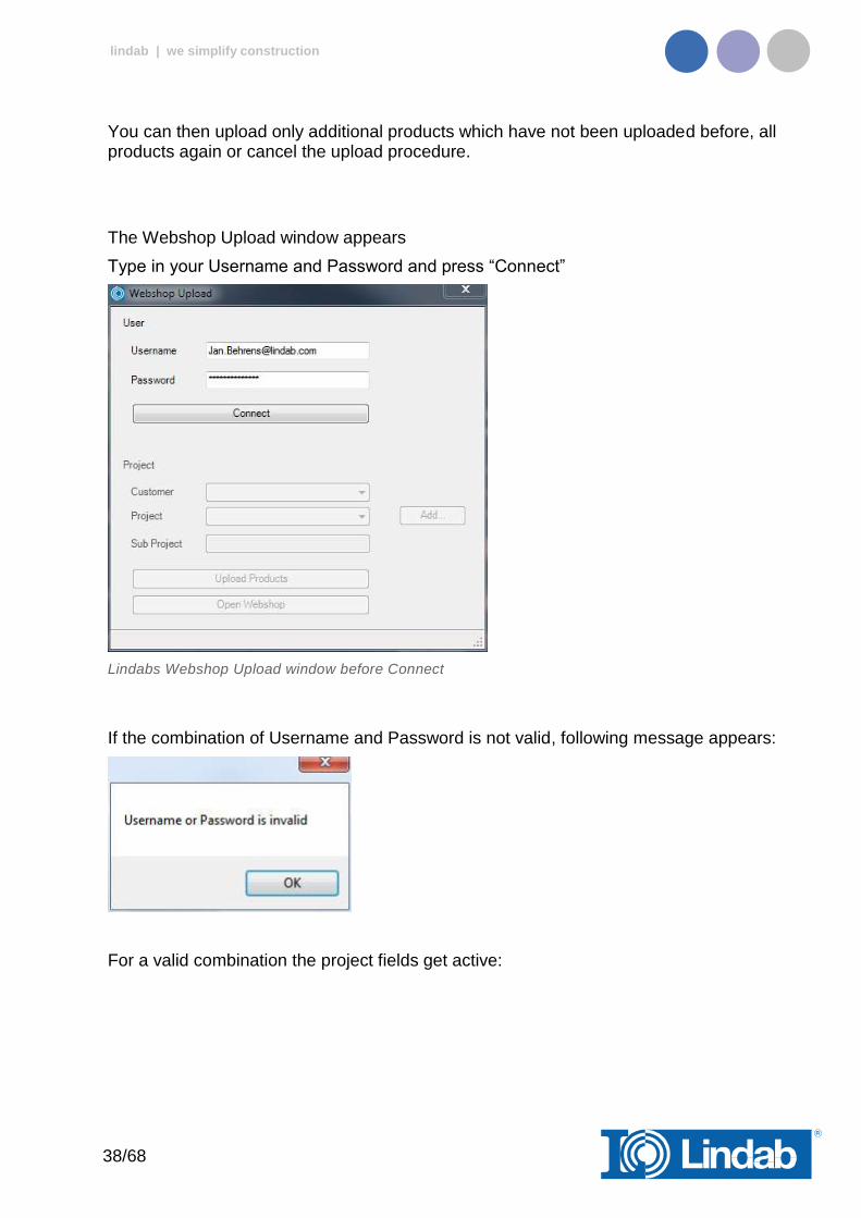
You can then upload only additional products which have not been uploaded before, all products again or cancel the upload procedure.
The Webshop Upload window appears
Type in your Username and Password and press “Connect”
Lindabs Webshop Upload window before Connect
If the combination of Username and Password is not valid, following message appears:
For a valid combination the project fields get active:
39/68
lindab | we simplify construction
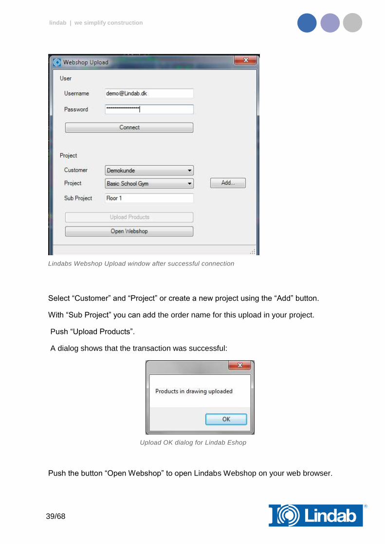
Lindabs Webshop Upload window after successful connection
Select “Customer” and “Project” or create a new project using the “Add” button.
With “Sub Project” you can add the order name for this upload in your project.
Push “Upload Products”.
A dialog shows that the transaction was successful:
Upload OK dialog for Lindab Eshop
Push the button “Open Webshop” to open Lindabs Webshop on your web browser.

40/68
lindab | we simplify construction
Lindab Webshop https://eshop.lindab.com/
This chapter will explain how to handle project uploads in the Lindab Webshop.
Note! The following images are based on Lindab Webshop Denmark. Other markets may have a different Webshop layout!
Lindab Webshop Frontpage
Press “CADvent” (Import)
A project list presents all your projects
Lindab Webshop Project List
Click on your current project
The project opens and all sub projects will be presented
41/68
lindab | we simplify construction
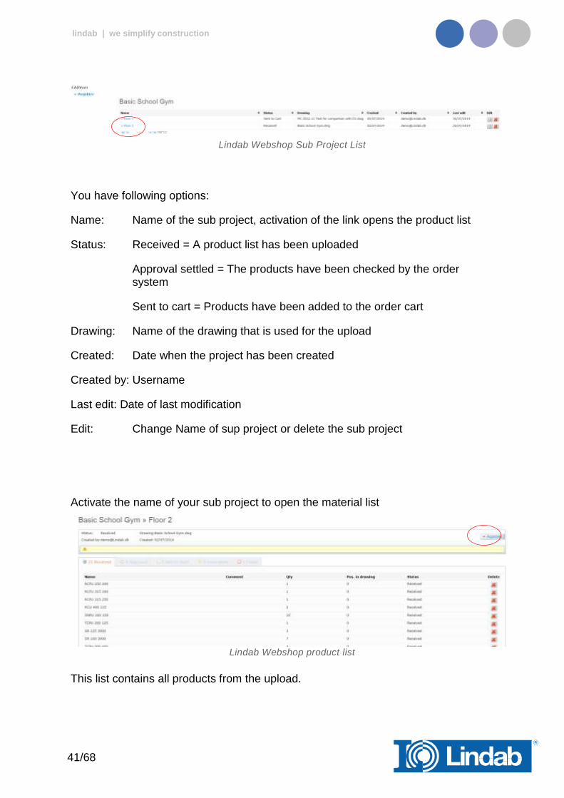
Lindab Webshop Sub Project List
You have following options:
Name: Name of the sub project, activation of the link opens the product list
Status: Received = A product list has been uploaded
Approval settled = The products have been checked by the order system
Sent to cart = Products have been added to the order cart
Drawing: Name of the drawing that is used for the upload
Created: Date when the project has been created
Created by: Username
Last edit: Date of last modification
Edit: Change Name of sup project or delete the sub project
Activate the name of your sub project to open the material list
Lindab Webshop product list
This list contains all products from the upload.
42/68
lindab | we simplify construction
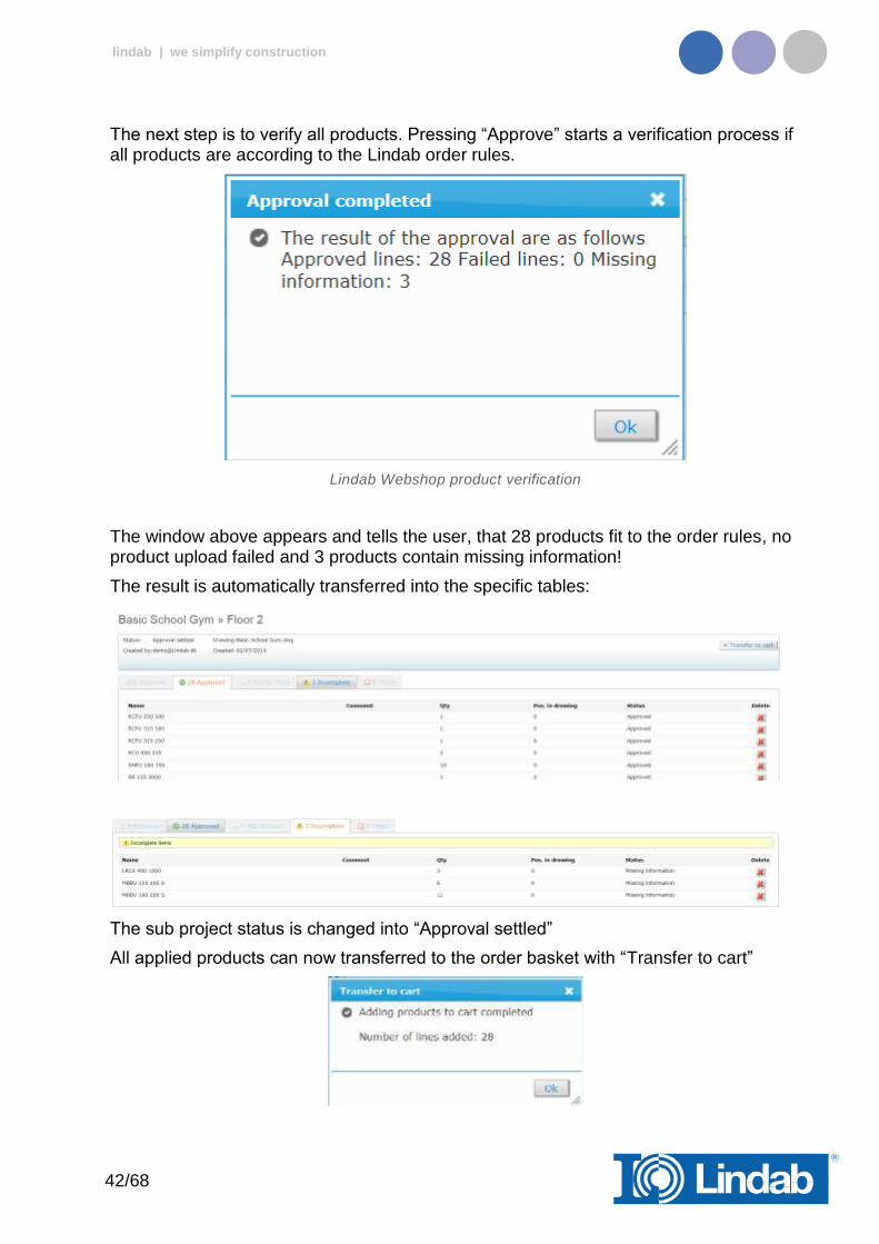
The next step is to verify all products. Pressing “Approve” starts a verification process if all products are according to the Lindab order rules.
Lindab Webshop product verification
The window above appears and tells the user, that 28 products fit to the order rules, no product upload failed and 3 products contain missing information!
The result is automatically transferred into the specific tables:
The sub project status is changed into “Approval settled”
All applied products can now transferred to the order basket with “Transfer to cart”
43/68
lindab | we simplify construction
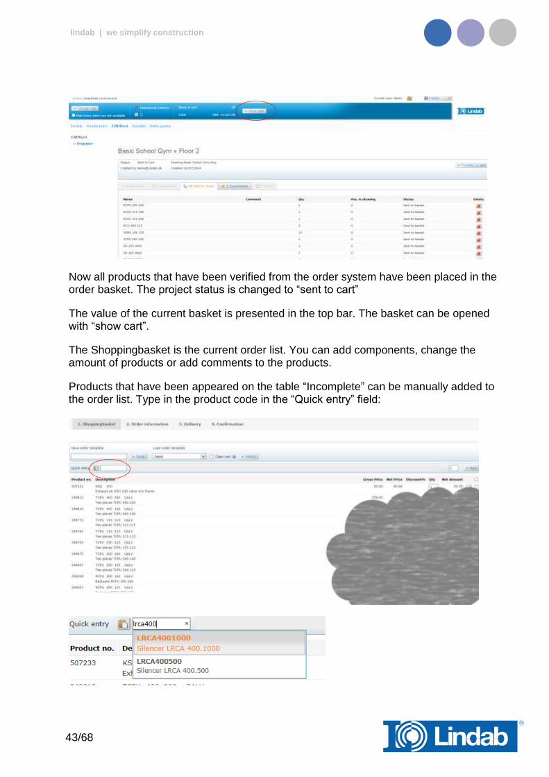
Now all products that have been verified from the order system have been placed in the order basket. The project status is changed to “sent to cart”
The value of the current basket is presented in the top bar. The basket can be opened with “show cart”.
The Shoppingbasket is the current order list. You can add components, change the amount of products or add comments to the products.
Products that have been appeared on the table “Incomplete” can be manually added to the order list. Type in the product code in the “Quick entry” field:
44/68
lindab | we simplify construction
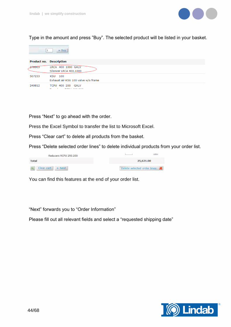
Type in the amount and press ”Buy”. The selected product will be listed in your basket.
Press “Next” to go ahead with the order.
Press the Excel Symbol to transfer the list to Microsoft Excel.
Press “Clear cart” to delete all products from the basket.
Press “Delete selected order lines” to delete individual products from your order list.
You can find this features at the end of your order list.
“Next” forwards you to “Order Information”
Please fill out all relevant fields and select a “requested shipping date”

45/68
lindab | we simplify construction
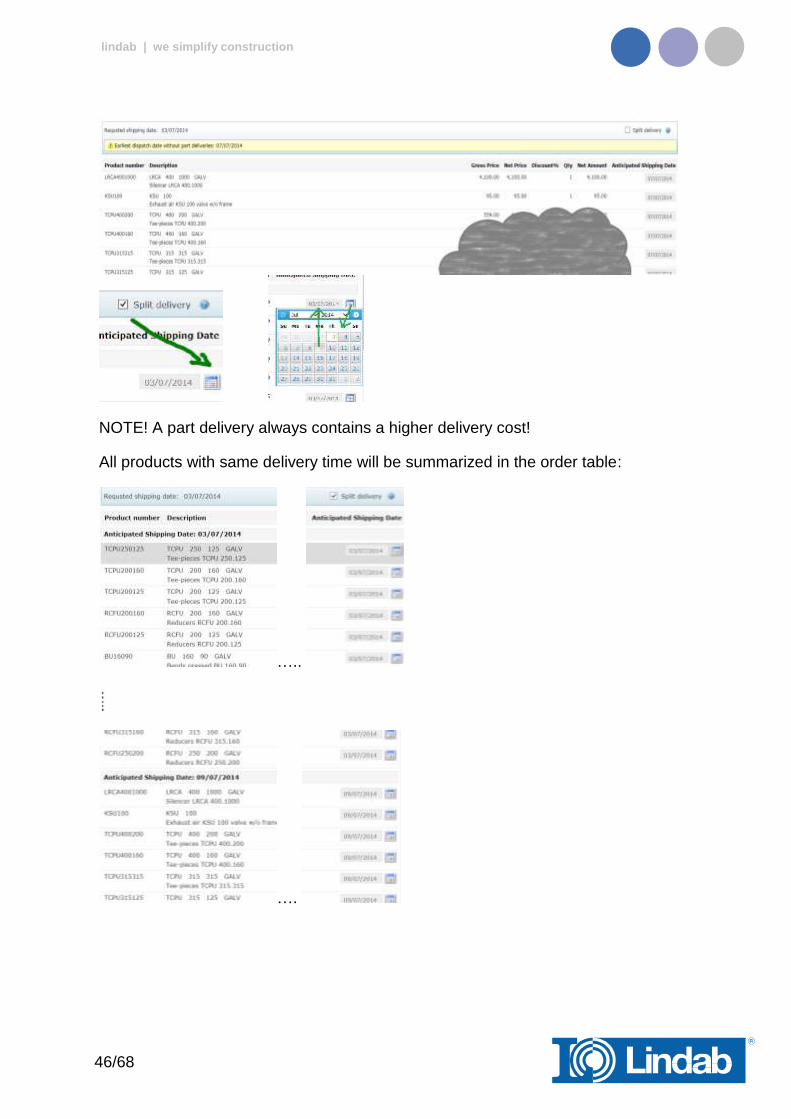
The system checks the delivery time of each product and offers a dispatch date without part deliveries. Activate Split delivery to deliver into parts.
Split delivery allows to change the delivery date for each component:
46/68
lindab | we simplify construction
NOTE! A part delivery always contains a higher delivery cost!
All products with same delivery time will be summarized in the order table:
…..
….

47/68
lindab | we simplify construction
Activate the checkbox “Approve order” and press “Approve order” to activate the order of the list of components.
48/68
lindab | we simplify construction
Add Space
The 3D Space element gives the user the possibility to create 3D objects in the drawing to create zones. The zones can be created as simple rectangular boxes (default) or as Polylines (Type P in the command Line, or activate Polyline on the right click menu) to create zones which follow the architecture.
The Space object allows the user to divide the drawing into several rooms or zones which can be uploaded to LindQST, the Lindab Quick Selection Tool, for selecting and calculating water and air products.
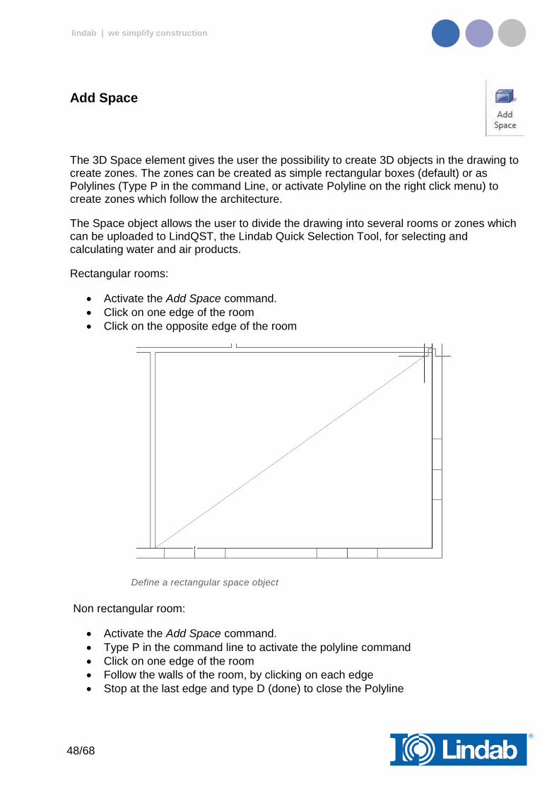
Rectangular rooms:
Activate the Add Space command.
Click on one edge of the room
Click on the opposite edge of the room
Define a rectangular space object
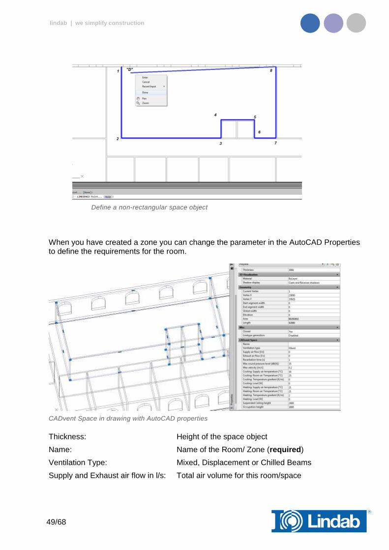
Non rectangular room:
Activate the Add Space command.
Type P in the command line to activate the polyline command
Click on one edge of the room
Follow the walls of the room, by clicking on each edge
Stop at the last edge and type D (done) to close the Polyline
49/68
lindab | we simplify construction
Define a non-rectangular space object
When you have created a zone you can change the parameter in the AutoCAD Properties to define the requirements for the room.
CADvent Space in drawing with AutoCAD properties
Thickness: Height of the space object
Name: Name of the Room/ Zone (required)
Ventilation Type: Mixed, Displacement or Chilled Beams
Supply and Exhaust air flow in l/s: Total air volume for this room/space
50/68
lindab | we simplify construction
Reverberation time in s: Sound reverberation time
Max. sound pressure level in dB(A): Max allowed sound level in the occupied zone
Max. velocity in m/s: Allowed average air velocity in the occupied zone
Occupation distance: Max. distance from displacement unit where the air velocity is allowed to prevail
Cool./Heat. Supply air temp. in °C: Temperature of the supply air
Cool./Heat. Room air temp. in °C: Temperature of the room air
Cool./Heat. Load in W: The required power for the room
Suspended ceiling height: Distance from floor to suspended ceiling
Occupation height: Height of the occupancy zone
You can edit the zone afterwards by dragging on the AutoCAD Grip points in the corners or on the lines.
lindQST Upload
After creating rooms / zones with the Add Space command you can upload the spaces into lindQST.
Note: The upload is not limited to a single room. You can upload multiple rooms in one process.
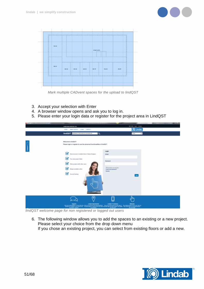
1. Activate the lindQST Upload command 2. Mark all spaces you like to update to your project in lindQST.
Note: You can all time add more spaces to your project in lindQST
51/68
lindab | we simplify construction
Mark multiple CADvent spaces for the upload to lindQST
3. Accept your selection with Enter 4. A browser window opens and ask you to log in. 5. Please enter your login data or register for the project area in LindQST
lindQST welcome page for non registered or logged out users
6. The following window allows you to add the spaces to an existing or a new project. Please select your choice from the drop down menu If you chose an existing project, you can select from existing floors or add a new.
52/68
lindab | we simplify construction
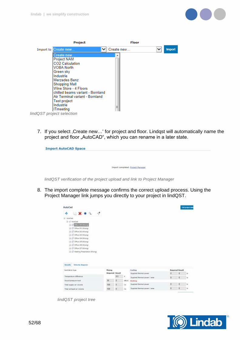
lindQST project selection
7. If you select ‚Create new…‘ for project and floor. Lindqst will automatically name the project and floor „AutoCAD“, which you can rename in a later state.
lindQST verification of the project upload and link to Project Manager
8. The import complete message confirms the correct upload process. Using the
Project Manager link jumps you directly to your project in lindQST.
lindQST project tree
53/68
lindab | we simplify construction
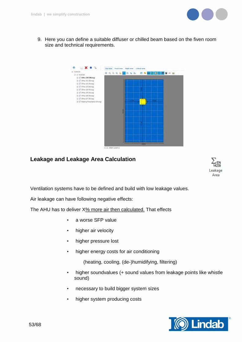
9. Here you can define a suitable diffuser or chilled beam based on the fiven room size and technical requirements.
Leakage and Leakage Area Calculation
Ventilation systems have to be defined and build with low leakage values.
Air leakage can have following negative effects:
The AHU has to deliver X% more air then calculated. That effects
• a worse SFP value
• higher air velocity
• higher pressure lost
• higher energy costs for air conditioning
(heating, cooling, (de-)humidifying, filtering)
• higher soundvalues (+ sound values from leakage points like whistle sound)
• necessary to build bigger system sizes
• higher system producing costs

54/68
lindab | we simplify construction
• higher Life Cycle Costs
• more inefficient real estate
with all resulting problems.
Leakage classes
The leakage classes according to the EN 13779 are defined in 4 classes: A to D, whereby D is the best class. The measurement procedures are defined in EN 12237, EN 1507, EN 1751 and EN 15727
A - (Class A not mentioned anymore in newest norms)
B - is the general minimum requirement
C - in a lot of situations the required minimum class
D - Lindab Safe = Lindab required leakage class
Definition of the leakage classes
The leakage classes are defined in leakage air flow per m² surface area at a specific static system pressure.
Leakage class Max. leakage per m²
(fmax)
l /(s.m²)
A 0,027 x pt0,65
B 0,009 x pt0,65
C 0,003 x pt0,65
D 0,001 x pt0,65
Pt = test pressure
The leakage area has to be calculated according to EN 14239.
You can find more details about the leakage test process here:
http://itsolution.lindab.com/lindabwebproductsdoc/pdf/documentation/ads/lindab/mounting/manual-ltest-1082_en-de-fr-se.pdf
( If the link below does not work, please go to www.Lindab.com and search for “Manual-Ltest”)
55/68
lindab | we simplify construction
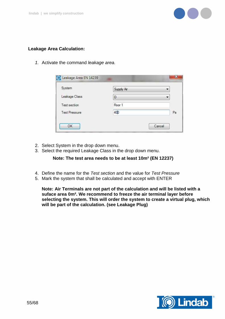
Leakage Area Calculation:
1. Activate the command leakage area.
2. Select System in the drop down menu. 3. Select the required Leakage Class in the drop down menu.
Note: The test area needs to be at least 10m² (EN 12237)
4. Define the name for the Test section and the value for Test Pressure 5. Mark the system that shall be calculated and accept with ENTER
Note: Air Terminals are not part of the calculation and will be listed with a suface area 0m². We recommend to freeze the air terminal layer before selecting the system. This will order the system to create a virtual plug, which will be part of the calculation. (see Leakage Plug)
56/68
lindab | we simplify construction
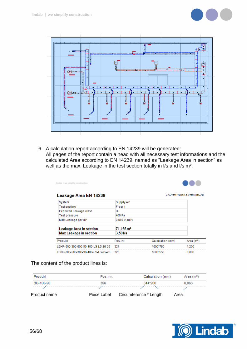
6. A calculation report according to EN 14239 will be generated: All pages of the report contain a head with all necessary test informations and the calculated Area according to EN 14239, named as ”Leakage Area in section” as well as the max. Leakage in the test section totally in l/s and l/s m².
The content of the product lines is:
Product name Piece Label Circumference * Length Area
57/68
lindab | we simplify construction
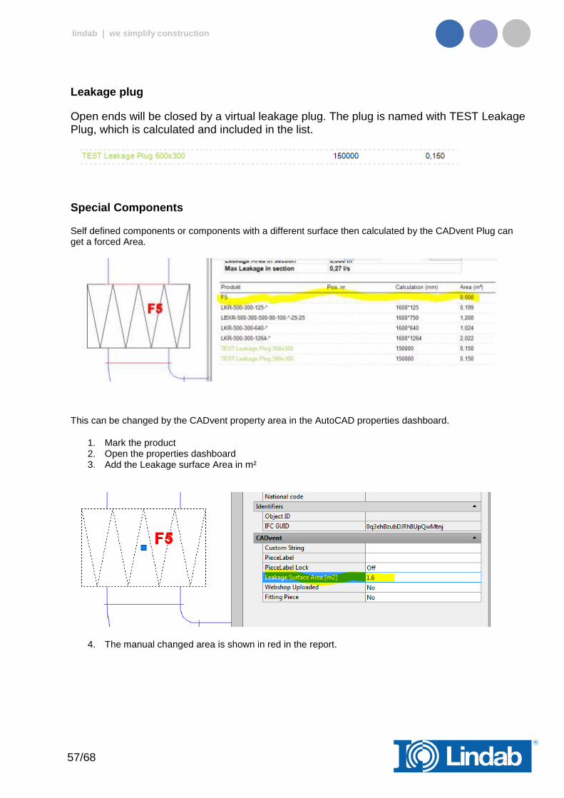
Leakage plug
Open ends will be closed by a virtual leakage plug. The plug is named with TEST Leakage Plug, which is calculated and included in the list.
Special Components
Self defined components or components with a different surface then calculated by the CADvent Plug can get a forced Area.
This can be changed by the CADvent property area in the AutoCAD properties dashboard.
1. Mark the product 2. Open the properties dashboard 3. Add the Leakage surface Area in m²
4. The manual changed area is shown in red in the report.
58/68
lindab | we simplify construction
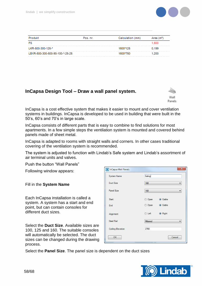
InCapsa Design Tool – Draw a wall panel system.
InCapsa is a cost effective system that makes it easier to mount and cover ventilation systems in buildings. InCapsa is developed to be used in building that were built in the 50’s, 60’s and 70’s in large scale.
InCapsa consists of different parts that is easy to combine to find solutions for most apartments. In a few simple steps the ventilation system is mounted and covered behind panels made of sheet metal.
InCapsa is adapted to rooms with straight walls and corners. In other cases traditional covering of the ventilation system is recommended.
The system is adjusted to function with Lindab’s Safe system and Lindab’s assortment of air terminal units and valves.
Push the button “Wall Panels”
Following window appears:
Fill in the System Name
Each InCapsa installation is called a system. A system has a start and end point, but can contain consoles for different duct sizes.
Select the Duct Size. Available sizes are 100, 125 and 160. The suitable consoles will automatically be selected. The duct sizes can be changed during the drawing process.
Select the Panel Size. The panel size is dependent on the duct sizes
59/68
lindab | we simplify construction
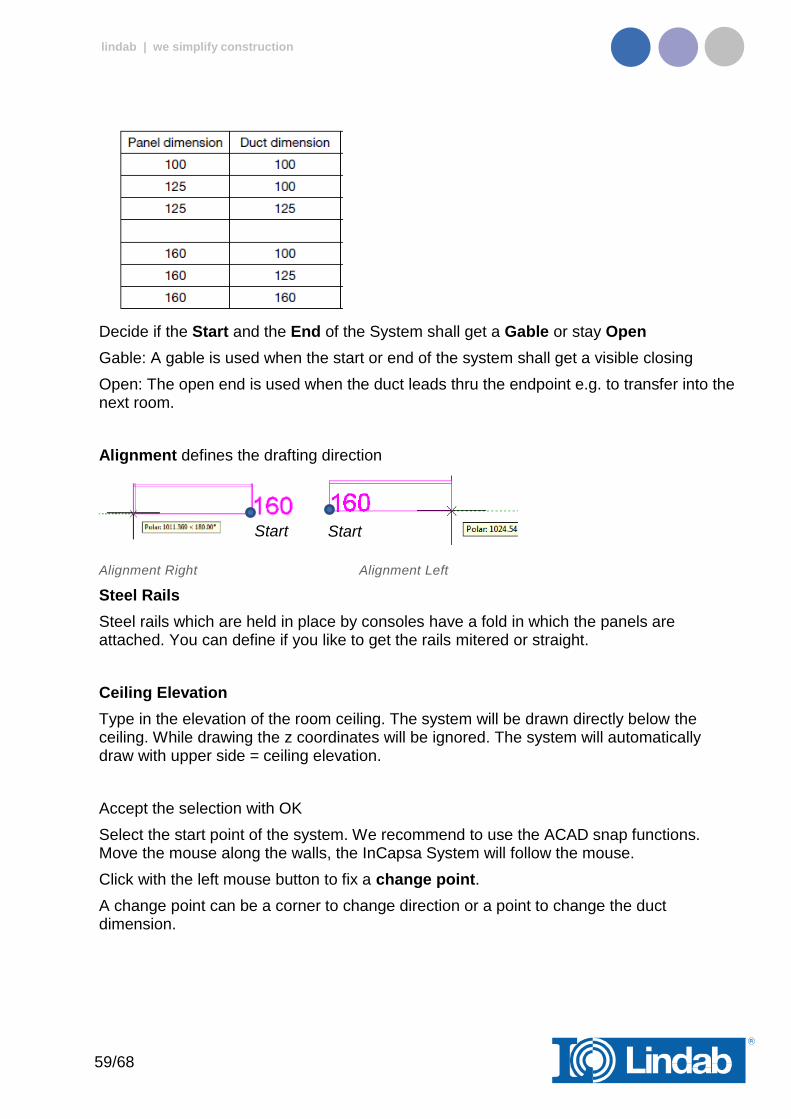
Decide if the Start and the End of the System shall get a Gable or stay Open
Gable: A gable is used when the start or end of the system shall get a visible closing
Open: The open end is used when the duct leads thru the endpoint e.g. to transfer into the next room.
Alignment defines the drafting direction
Alignment Right Alignment Left
Steel Rails
Steel rails which are held in place by consoles have a fold in which the panels are attached. You can define if you like to get the rails mitered or straight.
Ceiling Elevation
Type in the elevation of the room ceiling. The system will be drawn directly below the ceiling. While drawing the z coordinates will be ignored. The system will automatically draw with upper side = ceiling elevation.
Accept the selection with OK
Select the start point of the system. We recommend to use the ACAD snap functions. Move the mouse along the walls, the InCapsa System will follow the mouse.
Click with the left mouse button to fix a change point.
A change point can be a corner to change direction or a point to change the duct dimension.
Start Start
60/68
lindab | we simplify construction
Corner
Click with the left mouse button into a corner to define a change point. We recommend to use the ACAD snap functions.
Move the cursor to the next direction. Only 90° angles are possible.
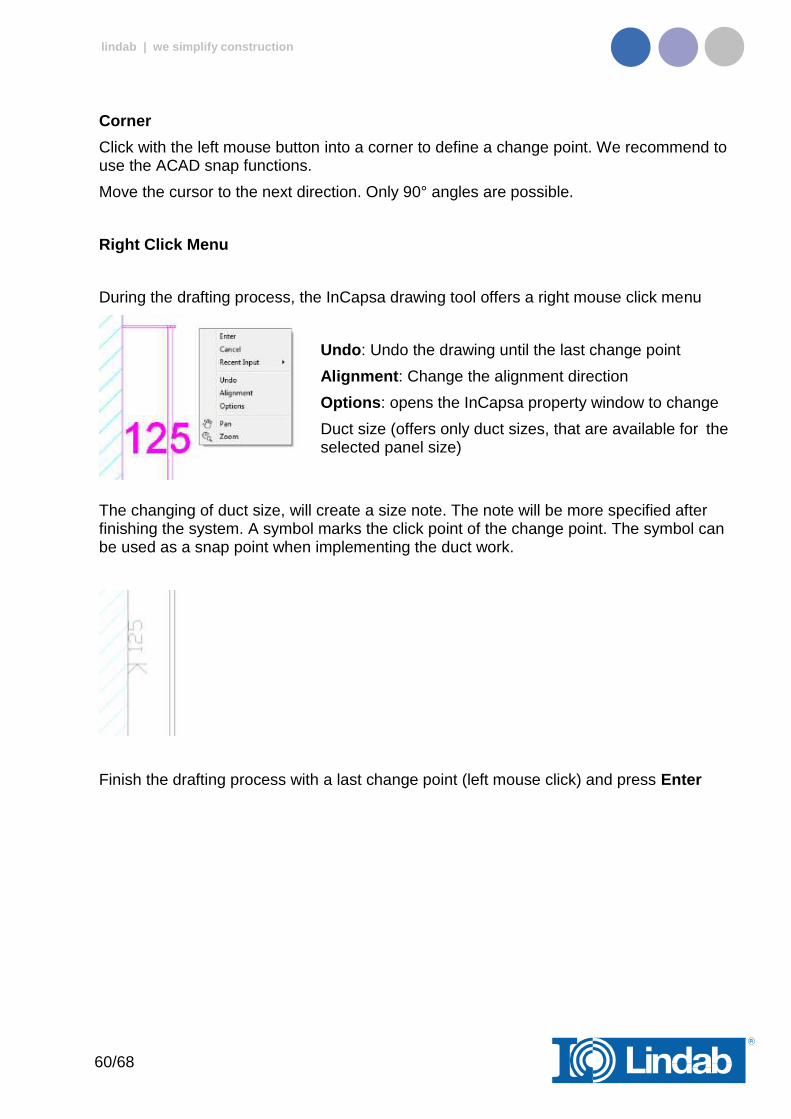
Right Click Menu
During the drafting process, the InCapsa drawing tool offers a right mouse click menu
Undo: Undo the drawing until the last change point
Alignment: Change the alignment direction
Options: opens the InCapsa property window to change
Duct size (offers only duct sizes, that are available for the selected panel size)
The changing of duct size, will create a size note. The note will be more specified after finishing the system. A symbol marks the click point of the change point. The symbol can be used as a snap point when implementing the duct work.
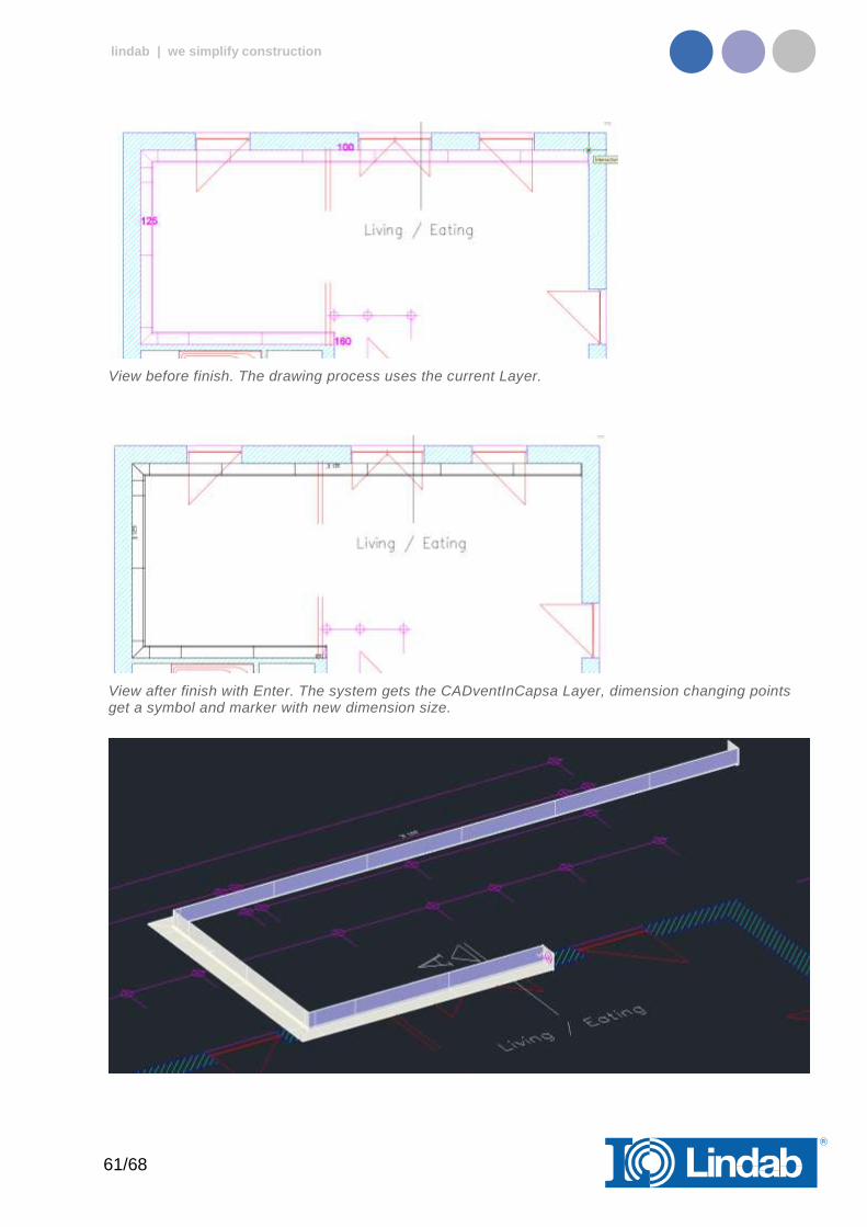
Finish the drafting process with a last change point (left mouse click) and press Enter
61/68
lindab | we simplify construction
View before finish. The drawing process uses the current Layer.
View after finish with Enter. The system gets the CADventInCapsa Layer, dimension changing points get a symbol and marker with new dimension size.

62/68
lindab | we simplify construction
InCapsa Design Tool – Draw a Free Panel system.
A Free Panel is a U-Panel that can be mounted at the ceiling or the wall.
Activate the button Free Panels
Following window appears.
Fill in System Name and Ceiling Elevation.
Note:
Only Duct Size and Panel Size 160 is available. Whereby the consoles are usable for duct sizes 100, 125 and 160.
Press OK
Select start and end point with the left mouse button.
Only straight systems can be drawn - angles are not available!
….
Start
End
63/68
lindab | we simplify construction
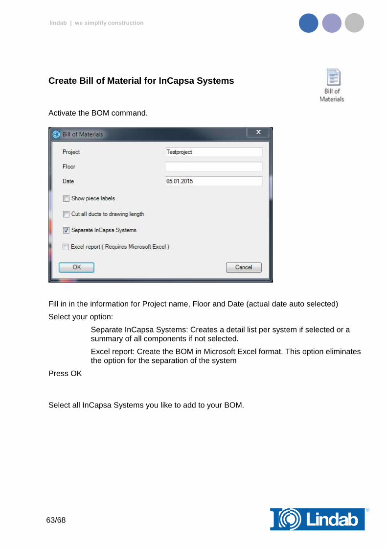
Create Bill of Material for InCapsa Systems
Activate the BOM command.
Fill in in the information for Project name, Floor and Date (actual date auto selected)
Select your option:
Separate InCapsa Systems: Creates a detail list per system if selected or a summary of all components if not selected.
Excel report: Create the BOM in Microsoft Excel format. This option eliminates the option for the separation of the system
Press OK
Select all InCapsa Systems you like to add to your BOM.
64/68
lindab | we simplify construction
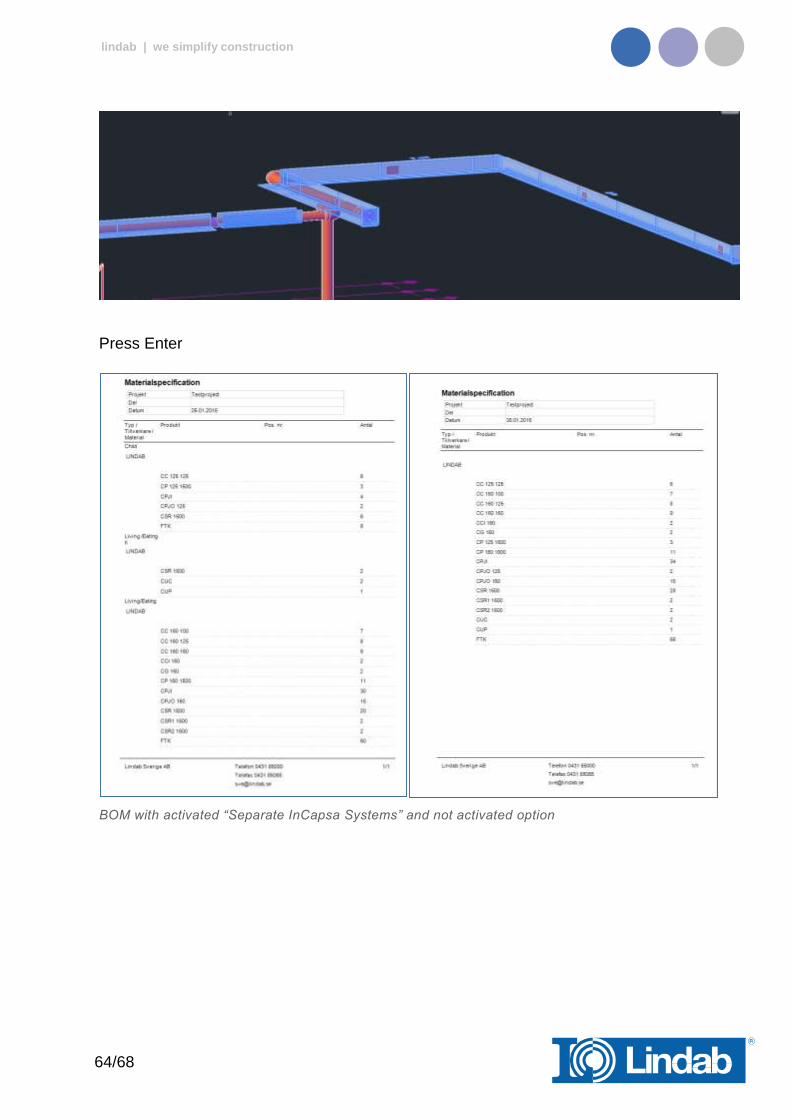
Press Enter
BOM with activated “Separate InCapsa Systems” and not activated option
65/68
lindab | we simplify construction
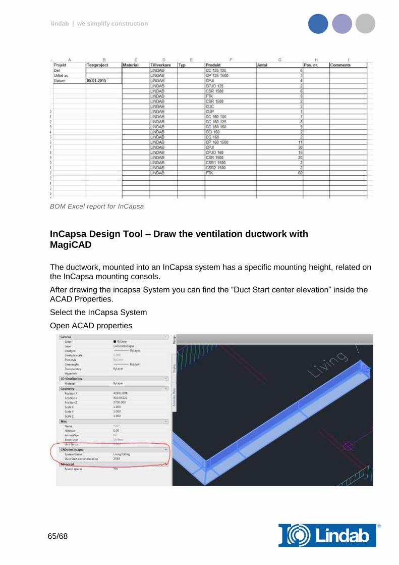
BOM Excel report for InCapsa
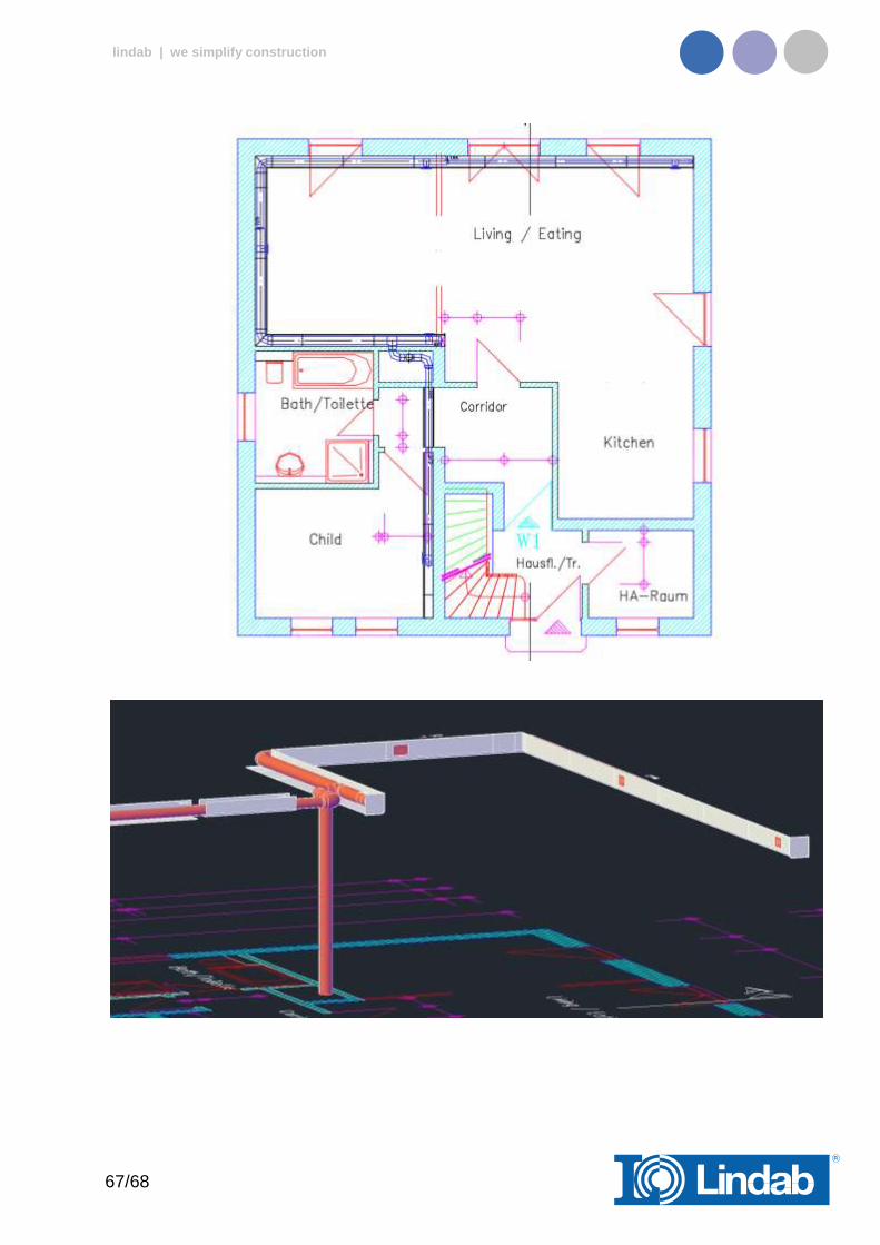
InCapsa Design Tool – Draw the ventilation ductwork with MagiCAD
The ductwork, mounted into an InCapsa system has a specific mounting height, related on the InCapsa mounting consols.
After drawing the incapsa System you can find the “Duct Start center elevation” inside the ACAD Properties.
Select the InCapsa System
Open ACAD properties
66/68
lindab | we simplify construction
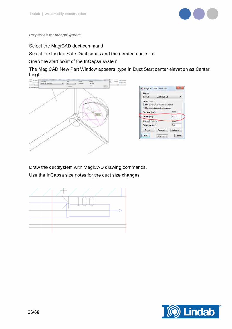
Properties for IncapaSystem
Select the MagiCAD duct command
Select the Lindab Safe Duct series and the needed duct size
Snap the start point of the InCapsa system
The MagiCAD New Part Window appears, type in Duct Start center elevation as Center height:
Draw the ductsystem with MagiCAD drawing commands.
Use the InCapsa size notes for the duct size changes
67/68
lindab | we simplify construction

68/68
lindab | we simplify construction
About
In the About button you can find information regarding version number of the CADvent plugin, which market is installed and contact information for technical assistance.
CADvent plugin About dialog


