Page 1
CAE Tool for Evaluation of Park Lock Mechanism in a DCT Transmission
CAE verktyg för utvärdering av parkeringslåsmekanism i en växellåda med
dubbla kopplingar
Rasmus Andreas Andersson
Fakulteten för hälsa, natur- och teknikvetenskap
Degree Project for Master of Science in Engineering, Mechanical Engineering
30hp
Supervisor Henrik Jackman
Examiner Jens Bergström
2017-07-19
Page 2
ii
ABSTRACT
A park lock mechanism is a device that is fitted to an automatic
transmission on a vehicle. The mechanism lock up the transmission
so that no rolling of the vehicle can be done when the vehicle is put
in the park position.
The aim of this thesis is to develop a method in order the evaluate
designs on a Park Lock Mechanism (PLM) that can be found in a
dual clutch transmission (DCT).
A Computer Aided Engineering (CAE) tool to calculate the output
that is required for an evaluation of a park lock mechanism design
will be created. The CAE tool shall calculate static, dynamic, and
snap torque on a ratchet wheel in a gradient, with or without a trailer,
also the minimum and maximum coefficient of friction between the
pawl and cone, pull out force, the maximum amount of rollback,
torque needed from the return spring, preload force from actuator
spring, and engagement speed.
The CAE tool created uses an Excel Visual Basics for Applications
(VBA) workbook for all calculations. The tool allows the user to
choose different vehicles with the required specification to evaluate
the values for that PLM.
The CAE tool will save time and cost if lots of different PLM’s are
going to be designed. The CAE tool has potential for future work
when more calculations can be added that can be in use for the
evaluation the PLM.
The CAE tool developed by the master thesis student calculates all
the required values for evaluation of a PLM design, executed in a
fast, efficient, and easy to use program.
Page 3
iii
SAMMANFATTNING
En parkeringslåsmekanism är en enhet som är monterad på en
automatisk växellåda på ett fordon. Mekanismen låser växeln så att
fordonet inta kan rulla när bilen sätts i parkeringspositionen.
Syftet med denna avhandling är att utveckla en metod för att
utvärdera konstruktioner på en pakeringslåsmekanism (PLM) som
finns i en dubbelkopplingstransmission.
Ett datorstött verktyg (CAE) som beräknar alla värden som krävs för
att utvärdera konstruktionen av en parkeringslåsmekanism ska tas
fram. CAE-verktyget ska beräkna statiskt, dynamiskt och
ögonblicksmoment på spärrhjulet i en lutning, med eller utan
släpvagn, minsta och maximala friktionskoefficient mellan spärrhake
och kon, utdragskraft, maximal tillbakarullning, vridmoment som
krävs från returfjädern, förspänningskraften från fjäderställdon och
ingreppshastigheten.
Det framtagna CAE-verktyget använder en Excel Visual Basic for
Applications (VBA) arbetsbok för alla beräkningar. Verktyget låter
användaren välja mellan olika fordon med den angivna
specifikationen för att utvärdera värdena för just den PLM.
CAE-verktyget sparar tid och kostnad om många olika PLM kommer
att konstrueras. CAE-verktyget har potential för framtida
förbättringsarbete då fler beräkningar kan läggas till och användas för
utvärderingen av PLM.
CAE-verktyget utvecklat av examensarbetsstudenten beräknar alla
nödvändiga värden för utvärdering av en PLM konstruktion, som
utförs i ett snabbt, effektivt och lättanvänt program.
Page 4
iv
ACKNOWLEDGMENTS
I would like to thank my supervisor Henrik Jackman at Citec through
Karlstad University for his contribution with advice and support
during this master thesis.
Special thanks to my supervisor at CEVT, Marcin Serafin for his
contribution with guidance and expertise during this master thesis. I
would also like to thank all the employees and consultants at CEVT
involved in this master thesis for support.
Finally, I want to express my fully gratitude to my parents and to my
significant other for the endless support and to encourage me through
five years of study. This achievement would not have been
imaginable without them. Thank you.
Rasmus Andreas Andersson
Göteborg, June 2017
Page 5
v
NOMENCLATURE
F Force
Fg Force from vehicle on slope
Ff Friction force
Ft Traction force
Fn Normal force
Fa Aerodynamic friction
Fr Rolling resistance
Fbraking Resulting force from braking
Fd Summarize disturbance force of not yet specified
effects
Fp Force acting on pawl from the ratchet wheel
Fpullout Force needed to pull out the cone when engaged
position
Favg,actuator,spring Average force needed to put pawl into engaged
position
τ Torque
τr Torque on ratchet wheel
τdyn,wheel Dynamic torque on wheel
τsnap,ratchet Dynamic torque on wheel
τw Torque on wheel
τr,s Torque that return spring must produce
mv Mass of the vehicle
mpawl Mass of the pawl
g Gravitational acceleration
ast Resulting acceleration from gravitational
acceleration acting on the vehicle
abraking Resulting acceleration from braking
afriction Acceleration from friction
amax,g Maximum acceleration acting on the vehicle
t Time
tbraking Time while braking
topen Time that pawl has to engage
r Radius
rw Radius on wheel
rratchet Radius on ratchet wheel to the rounding of the tooth
R Gear ratio
ω Angular velocity
ωwheel Angular velocity on the wheel of the vehicle
ωratchet Angular velocity on the ratchet wheel
I Moment of inertia
Ipawl Moment of inertia on pawl in rotation centre
α Angular acceleration
αpawl Angular acceleration needed to engage pawl
αSt Slope angle
µ Coefficient of friction
Page 6
vi
µS Static coefficient of friction
µp Coefficient of friction plough
µa Coefficient of friction abrasive
µpawl,cone Coefficient of friction between pawl and cone
θ Angle
θmax,ratchet Maximum degrees which ratchet wheel can turn
when parking pawl is engaged
θmax,Wheel Maximum degrees which wheel can turn when
parking pawl is engaged
θuphill,downhill Degrees rotation on ratchet wheel when vehicle goes
from uphill to downhill
θlift Degrees on pawl that lift the pawl into engaged
position
θlock Degrees on the cone that locks the pawl into engaged
position
θengaged,pawl Radians that pawl travel to engaged position from
when the pawl touch the ratchet wheel
θtan Degrees between the pawl is position through the
centre of gravity to the centre of rotation and the
horizon
υ Velocity
υ0 initial velocity
υmax,snap Maximum velocity which the vehicle can reach
when parking pawl is engaged from zero m/s
when snap case
υmax,dyn Maximum velocity which the vehicle reach for
dynamic case
n Number of teeth on ratchet wheel
dpawl,cone Distance between the rotation point of pawl to
centrum of cone
dmax,wheel Maximum distance which the vehicle can roll when
parking pawl is engaged
dF,r Lever between the rotation point of pawl to the
tangential force acting from ratchet wheel
dpawl,CoF Distance between the rotation point of pawl to centre
of gravity on pawl
ytot Total lift in y-direction
x1, x2 Distance in x-direction on cone
xtot total distance travelled by fork
Rz Surface roughness
Ra Surface roughness
Rn Surface roughness (n=1,2,3…9,10)
L Length of the tested area
z Height of the tops on the surface
Ap Area of ploughing
Alb Area from above
H Hardness
Page 7
vii
TABLE OF CONTENTS
1 INTRODUCTION ..................................................................................... 8
1.1 CEVT........................................................................................... 8
1.1.1 PROPULSION SYSTEM.............................................................. 8
1.1.2 SEVEN SPEED DUAL CLUTCH TRANSMISSION .................. 8
1.2 PROBLEM DESCRIPTION ....................................................... 9
1.3 ASSUMPTIONS ......................................................................... 9
1.4 PURPOSE AND GOAL .............................................................. 9
1.5 CARS........................................................................................... 9
1.6 TRANSMISSION ...................................................................... 10
1.7 DUAL CLUTCH TRANSMISSION ......................................... 10
1.8 PARK LOCK MECHANISM ................................................... 11
1.8.1 PAWL ......................................................................................... 13
1.8.2 RATCHET WHEEL ................................................................... 13
1.8.3 SPRING ACTUATOR ................................................................ 13
2 THEORY ................................................................................................. 14
2.1 FORCES ........................................................................................... 14
2.1.1 CAR 14
2.1.2 RATCHET WHEEL .............................................................................. 16
2.1.3 PAWL .................................................................................................... 17
2.2 TORQUE .......................................................................................... 17
2.2.1 STATIC ................................................................................................. 17
2.2.2 DYNAMIC TORQUE ........................................................................... 18
2.2.3 SNAP TORQUE .................................................................................... 19
2.3 FRICTION ........................................................................................ 21
2.3.1 SURFACE ROUGHNESS .................................................................... 21
2.3.2 WEAR ................................................................................................... 24
2.5 ENGAGEMENT SPEED ................................................................. 25
2.5.1 CONE .................................................................................................... 27
2.6 PULL OUT FORCE ......................................................................... 28
2.7 RETURN SPRING ........................................................................... 29
3 RESULT .................................................................................................. 30
3.1 DESIGN ........................................................................................... 31
4 DISCUSSION .......................................................................................... 35
4.1 GENERAL DISCUSSION ............................................................... 35
4.2 DESIGN DISCUSSION ................................................................... 36
4.3 FUTURE WORK ............................................................................. 38
5 CONCLUSION ........................................................................................ 39
6 REFERENCE ........................................................................................... 40
7 APPENDICES ......................................................................................... 42
7.1 LIST OF FIGURES .......................................................................... 42
Page 8
8
1 INTRODUCTION
Vehicles with an automatic gearbox are regulated by law to have a
mechanism in addition to the usual handbrake that prevents rollaway
after it has been parked [1]. The mechanism must withstand high
torque created by the vehicle and must therefore be designed to be
robust enough to hold for the life time of usage and not be able to
self-disengage.
1.1 CEVT
CEVT stands for China Euro Vehicle Technology. CEVT is a
relatively new car developer which was founded in 2013 and the
company is located at Lindholmen in Gothenburg. CEVT is a
subsidiary of the Chinese automotive manufacturer Geely, which also
owns Volvo Cars. Since Geely today makes so-called budget cars
and Volvo makes premium cars, Geely desired to have something in
between the brands. CEVT got the assignment to develop the new car
brand Lynk & Co. The first car out on the market will be Lynk & Co
01 which is built on CEVT’s Compact Modular Architecture (CMA)
platform [2]. This platform will also be used in future Volvo cars [3].
1.1.1 PROPULSION SYSTEM
This thesis was carried out in the propulsion system department at
CEVT. Propulsion system is the department which is in charge of
everything related to taking the vehicle forward, backward or
standing still after parked. The propulsion system department is
divided into different areas where transmission is one of them.
1.1.2 SEVEN SPEED DUAL CLUTCH TRANSMISSION
7DCT account for 7-speed Dual Clutch Transmission. A DCT
function as two manual gearboxes with two output shafts which
automatically selects the gears in advance. For the first output shaft;
second, fourth, sixth and reversed gears can be found and for the
second output shaft; first, third, fifth and seventh gear including
parking lock mechanism can be found [4].
Page 9
9
1.2 PROBLEM DESCRIPTION
CEVT is the owner of their own 7DCT. For further development of
the 7DCT to fit future vehicles, modifications need to be done on the
park lock mechanism to fit the new requirements. CEVT doesn’t
have the resource to make calculations on all new PLM’s thus they
need a tool for these kind of calculations on the PLM.
1.3 ASSUMPTIONS
The calculations are from ideal cases e.g. 100% efficiency in the
gearbox and differential, perfect contact points and no sliding of tires.
Small differences between calculated and tested results may occur.
Calculations are simplified but it is considered to have little impact
on the result. Things that have been neglected are friction between
pawl and shaft/bracket, friction between the cone and actuator rod
when cone engaging the pawl into parked position, no suspension or
damping occurs, aerodynamic friction due to small velocities, perfect
fit for cone on actuator rod. The vehicle is assumed to be a front-
wheel drive vehicle so the PLM will only affect the front wheels of
the vehicle.
1.4 PURPOSE AND GOAL
The purpose and goal of the thesis is to develop a Computer-Aided
Engineering (CAE) tool in the form of an Excel program. The
program should take input data about the geometry and give out what
forces the new geometry will be exposed to. These values can later
be used as a background for Finite Element Method (FEM) analysis.
1.5 CARS
The cars powertrain uses many parts to propel the car. The parts
included in the powertrain are engine, clutch, transmission,
differential, drive shafts and wheels. The engine gives torque through
the clutch to the transmission which changes the gear ratio and
therefore the torque. The torque from the transmission continues
through the differential that provides torque to the wheels. The final
drive is the gear ratio from the differential [5]. In this thesis it’s the
other way around. A car parked in a slope causes a reaction force that
wants to propel the car down the slope. A park lock mechanism will
prevent rollaway by taking up the reaction forces.
Page 10
10
1.6 TRANSMISSION
The transmission on a vehicle takes the output power from an engine
and gives the correct torque to the output shaft which makes the
wheels rotate to propel the vehicle or to have the vehicle stationary
with the engine still running. Today there are two different kinds of
transmissions in vehicles. There is the manual transmission where the
user of the vehicle needs to manually shift between gears and the
automatic gearbox which makes the shifting for the user. The
automatic gearbox comes in a lot of variations like a dual clutch
transmission (DCT) or planetary automatic transmission [6]. The
transmission in this thesis is about the dual clutch transmission.
1.7 DUAL CLUTCH TRANSMISSION
The DCT resolved problems that planetary automatic transmissions
have like efficiency drop due to the torque-converter [4]. The DCT is
an automatic transmission that operates two manual gear sets with
two clutches. One clutch and gear set is set at odd gears and the other
is set at even gears. This is often packed coaxial to reduce the volume
of the transmission. While one clutch is engaged the other clutch and
gear set will preselect a target gear. In the gearshift one clutch will
disengage in the same time as the other clutch will engage to make a
seamless gearshift. This will make the vehicle to never have any
torque drops and a steady acceleration. The clutches can either be wet
clutches or dry clutches [6]. The wet clutch uses oil as a cooling fluid
because heavy torque produces heat [7]. The gear shifting is made by
a gear actuator and the clutch is operated by a hydraulic clutch
actuator (HCA). When the vehicle is parked both HCA that controls
the clutches will disengage the clutches. This will make the vehicle
rollaway if any external force is applied to the vehicle. To prevent
this, a park lock mechanism is fitted to the transmission.
Page 11
11
1.8 PARK LOCK MECHANISM
The park lock mechanism (PLM), is put on one of the output shafts in
the transmission to prevent any kind of rolling of the vehicle when
the vehicle is put in the “park” position [8]. The PLM is by U.S. law
regulated on vehicles with automatic transmission that weighs
4536kg or less. The law is for theft protection to reduce incidences of
crashes that are a result form an unauthorized use of the vehicle and
to reduce the incidences of crashes resulting from rollaway of a
parked vehicle with an automatic transmission [1]. The Federal
Motor Vehicle Safety Standards (FMVSS) 114 doesn’t say anything
about the solution of preventing the rollaway of the vehicle and the
park lock mechanism is one solution to the problem.
The park lock mechanism investigated in this thesis consists of a
pawl, ratchet wheel, actuator and a cone that pushes the pawl into
lock, see Figure 1 [9], [10] and [11]. The vehicle, when moving at a
high speed and the park position is engaged, the park pawl must not
engage into the ratchet wheel but instead slip until the vehicle is
slowed down until the engagement speed is reached. Locking up the
parking mechanism at higher speeds causes high stresses, wear,
fatigue, and failure on the park lock and on other transmission
components.
Figure 1. Park lock mechanism, (1) ratchet wheel, (2) pawl, (3) shaft, (4) guide
block, (5) cone, (6) actuator spring, (7) actuator rod, (8) fork, (9) return spring, (10)
bracket.
Page 12
12
Figure 2. Schematic picture on rollback on the PLM, both rollaway when park up
the slope and down the slope.
When the driver parks the vehicle in a slope the PLM must prevent
rollback before the maximum rollback distance is reached to stop the
vehicle, see Figure 2. This also means that the speed that the vehicle
is reaching before the park pawl is engaged must be less than the
park lock’s engagement speed. The speed that the vehicle will reach
is a result from approximately one tooth passing on the ratchet wheel.
The PLM must be able to disengage when the vehicle has been
parked on a slope for an extended period of time, must stay engaged
when the pawl has reached the engaged position and must be
designed not to disengage while in engaged position.
The gear actuator is the component that selects the gear or puts the
vehicle in parked position. The gear actuator goes through the hole
on the fork, see Figure 1. When the gear actuator turn to select
parking position, the fork on the PLM is displaced so that the spring
actuator with the cone is pushed against the guide block and the
pawl. The guide block is stationary but the pawl will rotate to engage
position. When the fork has done a full displacement, the pawl is in
parked position and will lock up the transmission, see Figure 3.
Figure 3. To the left, PLM disengaged. To the right, PLM engaged.
To make a safe PLM there are some design requirements and product
specification needed from the customer like engagement speed,
rollaway distance and maximum slope grade, and there is a couple of
parameters to be researched like the mass and weight transfer of the
vehicle, final drive ratio, park ratchet wheel and park pawl geometry,
and park lock components [12]. The ratchet wheel and pawl must be
constructed so that when engaged the system is self-ejecting, this
means that when the park position is disengaged the reaction force on
Page 13
13
the pawl can’t hold in place and will jump out of the engaged
position. This is to prevent to get stuck when parked on a slope after
disengaging the park position. In engaged position the combination
of pawl, cone and sliding block will self-lock the system. This will
result in a large torque from the ratchet wheel and will make the cone
even harder to disengage [13].
1.8.1 PAWL
The pawl in the park lock mechanism is the one thing that locks up
the transmission. It is designed as an arm with a tooth on the end.
There is also a chamfer on the opposite side of the tooth that will
slide against the cone to engage the park lock. A spring is fitted to the
pawl to prevent it to engage when it should be disengaged e.g.
driving on a bumpy road that makes the pawl rotates up and down.
1.8.2 RATCHET WHEEL
The ratchet wheel is a notched wheel that is fasten on one of the
output shafts. The pawl will engage when the tooth fits in one of the
notches and therefor lock the output shaft.
1.8.3 SPRING ACTUATOR
The spring actuator is the part that pushes the pawl into engaged
mode or disengaged mode. It uses a pin, spring and a cone to do this.
The spring must be able to push the pawl into engagement even when
the vehicle is rolling. In the case when the pawl is engaged on a
tooth, the spring actuator will still continue with the full movement
but the cone will be pushed against the pawl without movement until
the ratchet wheel will turn to a notch.
Page 14
14
2 THEORY
Section 2 will derive all the equations that will be used in the CAE
tool. It will describe how the forces acting on the vehicle will affect
the PLM.
2.1 FORCES
Force can be described as a push or a pull. A force has a magnitude
and a direction.
2.1.1 CAR
The elements that effects the dynamic forces of a vehicle are the
mass of the vehicle, mv, and the acceleration, dυ(t)/dt, which is the
result of the traction force, Ft, the aerodynamic friction, Fa, the
rolling resistance, Fr, the gravitational force on the slope, Fg, and
other disturbance forces, Fd, included in Equation 1, see Figure 4.
Equation 1
tFtFtFtFtFtdt
dm dgratv
Figure 4. Schematic figure of reaction forces acting on a vehicle while in motion.
When the vehicle is standing still on a flat surface it is normal to the
gravitational force. The gravitational force is acting on the vehicle,
but reaction force from the surface prevent the vehicle from falling
through the surface. When the vehicle is located on a gradient, the
Page 15
15
reaction force acting on the vehicle will result in an acceleration
parallel with the slope due to the gravitational force and the normal
forces from the surface, see Figure 5.
Figure 5. Reaction forces on a vehicle that stands on a slope.
The reaction force mvgsinαSt, will propel the vehicle down the slope if
there isn’t anything stopping it. So when the vehicle has its parking
lock system engaged, the wheels will be locked resulting in, that the
frictional force reacting on the tires of the vehicle will keep it in
place. The frictional force, Ff, works perpendicular to the normal
force, Fn, of the vehicle and the CoF, µ, as described in Equation 2.
The PLM stops the vehicle form rolling, resulting in the force
holding the vehicle, Fg, from the mass of the vehicle, mv,
gravitational acceleration, g, and the angle of the slope, αSt, see
Equation 3.
Equation 2
nf FF
Equation 3
Stvg gmF sin
The friction force, Ff, on the tires will cause a torque, τw, on the
wheel which will be transferred through the drive shafts, differential,
final drive gear ratio, R, and last to the park ratchet wheel that will
have the counter torque, τr, because of the reaction force from the
park pawl, see Figure 6.
Page 16
16
Figure 6. Schematic figure over the torque transfer from wheels to ratchet wheel.
The minimum static coefficient of friction, µs, needed without any
sliding can be decided by the angle, αSt of which the object is not
sliding when located on a gradient, see Equation 4.
Equation 4
SSt tan
2.1.2 RATCHET WHEEL
The ratchet wheel is the notched wheel that is fastened on the output
shaft. This wheel needs to take up all the torque and force caused by
the vehicle. The ratchet wheel doesn’t necessarily need to be
symmetrical due to the geometry and placement of the pawl, see
Figure 7. This mean that they can have different angles on each side
of the tooth. This geometry will make the pawl self-disengage when
the cone has left engage position. The size of the ratchet wheel,
numbers of teeth and width of the tooth on the ratchet wheel and
pawl will decide the angular movement on the output shaft which in
turn will determine the rollback of the vehicle. The angle on the tooth
will determine the normal force acting on the tooth. Friction will act
on the ratchet wheel and the pawl when the pawl is engaged to one of
the ratchet wheel notches. The surface roughness, if too rough or
fine, can also contribute to the friction.
Page 17
17
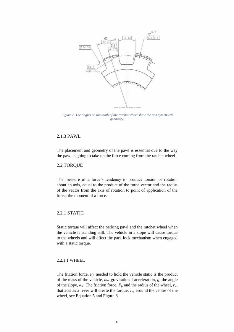
Figure 7. The angles on the tooth of the ratchet wheel show the non symetrical
geometry.
2.1.3 PAWL
The placement and geometry of the pawl is essential due to the way
the pawl is going to take up the force coming from the ratchet wheel.
2.2 TORQUE
The measure of a force’s tendency to produce torsion or rotation
about an axis, equal to the product of the force vector and the radius
of the vector from the axis of rotation to point of application of the
force; the moment of a force.
2.2.1 STATIC
Static torque will affect the parking pawl and the ratchet wheel when
the vehicle is standing still. The vehicle in a slope will cause torque
to the wheels and will affect the park lock mechanism when engaged
with a static torque.
2.2.1.1 WHEEL
The friction force, Ff, needed to hold the vehicle static is the product
of the mass of the vehicle, mv, gravitational acceleration, g, the angle
of the slope, αSt. The friction force, Ff, and the radius of the wheel, rw,
that acts as a lever will create the torque, τw, around the centre of the
wheel, see Equation 5 and Figure 8.
Page 18
18
Equation 5
wStvwfw rgmrF sin
Figure 8. Torque acting on the wheel.
2.2.1.2 RATCHET WHEEL
The torque from the wheel, τw, is transferred to the park ratchet
wheel. Between the ratchet wheel and the wheel is a differential that
has a gear ratio, R. Equation 6 calculate the torque on the ratchet
wheel, τr.
Equation 6
R
wr
2.2.2 DYNAMIC TORQUE
Dynamic torque is the needed torque to get a full stop of the vehicle
when the vehicle is traveling at a certain velocity.
2.2.2.1 WHEEL
Dynamic torque will act on the wheel, τdyn,wheel, when the vehicle
travels in a chosen velocity, υ, and the PLM is engaged. The force to
stop the vehicle is the friction force, Ff, between the tires and the
road. The system in Figure 9 shows that the gravitational force, mvg,
contributes to the normal forces, FN1 and FN2. Only FN2 contributes to
Page 19
19
the frictional force, Ff. The frictional force for a static case must be
equal or less than the normal force, FN2, times the static CoF, µs,
between the tire and the surface. The force, Ff, needed to stop the
vehicle depends on the time from when the pawl is engaged to when
the vehicle has come to a full stop. The time is known from tests. The
dynamic torque acting on the wheel, τdyn,wheel, is calculated by the
mass of the vehicle, mv, braking acceleration which is the initial
velocity, υ0, final velocity, υ, time for braking, tbraking, and the radius
of the wheel, rw, by Equation 7.
Figure 9. Schematic image of vehicle stopping.
Equation 7
w
braking
vwfwheeldyn rt
vvmrF 0
,
2.2.2.2 RATCHET WHEEL
Dynamic torque will act on the ratchet wheel if the vehicle is moving
and the PLM is engaged. The pawl will stop the rotation of the
ratchet wheel and therefore stop the rotation of the wheels on the
vehicle. The torque transferred from the wheel of the vehicle to the
ratchet wheel is shown in Equation 6.
2.2.3 SNAP TORQUE
Snap torque, also called snap releases torque, occurs when the
vehicle is parked on a slope and the PLM is disengaged and engaged
directly after each other to make the vehicle move what is equivalent
to one tooth passing on the ratchet wheel. This will make the vehicle
accelerate down the slope and gain a certain speed before the PLM
stops the vehicle. The system for snap torque is shown in Figure 10.
The braking force is the sum of the force from the slope and the
friction. The friction acceleration will act on the wheel, afriction, due to
Page 20
20
the braking acceleration, abraking, and the acceleration from the slope,
aSt, see Equation 8.
Figure 10. Forces acting on the vehicle when snap case.
Equation 8
StbrakingfrictionStvfrictionvbrakingv aaagmamam sin
The acceleration of braking is calculated by knowing the velocity, υ,
which is zero in this case, initial velocity, υ0, and time for braking,
tbraking, which is known from real life tests, see Equation 9. The initial
velocity, υ0, is calculated by constant energy. For constant energy the
acceleration from the slope, aSt, and the maximum distance the
vehicle can travel before the pawl stops the rotation of the ratchet
wheel, dmax,wheel, see Equation 10.
Equation 9
braking
brakingt
vva 0
Equation 10
wheelStdav max,0 2
The distance, dmax,wheel, is the product of how long the vehicle has
travelled when the ratchet wheel passes one tooth and the number of
teeth is known on the ratchet wheel, n, see Equation 11.
Equation 11
180
/360max,
R
nrd wwheel
Page 21
21
The torque on the ratchet wheel for the snap case, τsnap,ratchet, is
calculated by the mass of the vehicle, mv, friction acceleration, afriction,
radius of the wheel, rw, and the final drive gear ratio, R, see Equation
12.
Equation 12
R
ram wfrictionv
ratchetsnap ,
2.3 FRICTION
The friction is the resistance force that resists an object’s motion
relative over another surface. There are two main frictions; static
friction and dynamic friction. Static friction occurs when there is no
relative motion between the surfaces and dynamic friction is when
two surfaces is relative moving on each other. The coefficient of
friction is the fraction that shows the relation between the friction
force and the normal force [14].
2.3.1 SURFACE ROUGHNESS
The surface roughness is important for the details that will be sliding
against each other.
There are different ways of calculating the surface roughness. Ra and
Rz are two ways to calculate surface roughness. Ra is calculated by
knowing the height of the peaks on the surface, z(x), and the length
on which the peaks are measured over, L, and Rz is a function of the
average of height of peaks, R1-5, and the average of depth of valleys,
R6-10, see Equation 13 and Equation 14. The difference between Ra
and RZ is that Ra is calculated by the measurements of the average
length between the valleys and peaks and then divided from the mean
line on the whole surface. This makes Ra averages out all the valleys
and peaks of the roughness profile and neutralizes some of the few
points that is extreme and therefore not have such big impact in the
final results. The RZ value is a calculation of measurements of the
vertical distance from the highest peak to lowest valley within five
sampling lengths, then averaging these distances. Because of that RZ
only uses five highest and lowest values have a bigger impact on the
values of RZ [15]. High values of the surface roughness on the contact
surfaces can result in high CoF which can cause self-locking of the
PLM.
Page 22
22
Equation 13
55
10987654321 RRRRRRRRRRRZ
Equation 14
L
a dxxzL
R0
1
2.3.1.1 THE CONSEQUENCES OF ADHESION THEORY
Adhesion theory of friction constitutes of interatomic forces that act
over atomic contact spots. These forces, called adhesion, are causing
the material to be sheared upon the relative movement between the
surfaces. This is still hard to detect because there will be almost no
noticeable adhesion e.g. between metals. Adhesion acts during
sliding contact between surfaces and at the same time shear is acting.
The shear helps to expose clean metal at the top most surfaces. This
in which it provides much higher adhesive forces. To measure the
adhesive force, the applied normal force must be relieved. During the
unloading, the surfaces are decompressed as the elastic tension
around the contact spots where the contact bridges are to be
deformed to that point that the bridges breaks. When the load is
completely relieved, remains only a few small contact bridges. These
bridges will barely have any measurable adhesion, see Figure 11.
There are exceptions, where one can measure a significant adhesion.
Clean metal surfaces for adhesion significantly during high vacuum
conditions. For extremely soft materials (where the elastic relaxation
is relatively very small) one can get measurable adhesion by
squeezing on to do a little twisting motion to remove surface oxide
from the contact patches. There are also cases where one gets a
strong adhesion after vibration contact under dry conditions. It is
even possible to join the metals by deliberately exposing them to
extremely high contact pressure and high sliding speed [14]. The
wear on the different part is worth calculating for lifetime
calculations. This thesis will calculate during ideal cases and will
neglect wear by adhesion in the calculations for the CAE tool. Wear
by adhesion is worth mention for the high forces on small contact
points on the different parts on the PLM.
Page 23
23
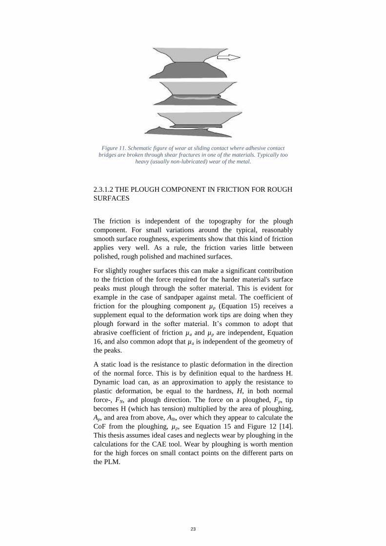
Figure 11. Schematic figure of wear at sliding contact where adhesive contact
bridges are broken through shear fractures in one of the materials. Typically too
heavy (usually non-lubricated) wear of the metal.
2.3.1.2 THE PLOUGH COMPONENT IN FRICTION FOR ROUGH
SURFACES
The friction is independent of the topography for the plough
component. For small variations around the typical, reasonably
smooth surface roughness, experiments show that this kind of friction
applies very well. As a rule, the friction varies little between
polished, rough polished and machined surfaces.
For slightly rougher surfaces this can make a significant contribution
to the friction of the force required for the harder material's surface
peaks must plough through the softer material. This is evident for
example in the case of sandpaper against metal. The coefficient of
friction for the ploughing component µp (Equation 15) receives a
supplement equal to the deformation work tips are doing when they
plough forward in the softer material. It’s common to adopt that
abrasive coefficient of friction µa and µp are independent, Equation
16, and also common adopt that µa is independent of the geometry of
the peaks.
A static load is the resistance to plastic deformation in the direction
of the normal force. This is by definition equal to the hardness H.
Dynamic load can, as an approximation to apply the resistance to
plastic deformation, be equal to the hardness, H, in both normal
force-, FN, and plough direction. The force on a ploughed, Fp, tip
becomes H (which has tension) multiplied by the area of ploughing,
Ap, and area from above, Alb, over which they appear to calculate the
CoF from the ploughing, µp, see Equation 15 and Figure 12 [14].
This thesis assumes ideal cases and neglects wear by ploughing in the
calculations for the CAE tool. Wear by ploughing is worth mention
for the high forces on small contact points on the different parts on
the PLM.
Page 24
24
Equation 15
lb
p
lb
p
N
p
pA
A
HA
HA
F
F
Equation 16
pa
Figure 12. Schematic figure of ploughing.
2.3.2 WEAR
Wear in sliding contact may occur when a solid surface sliding
against another. This load may cause numerous surface damage
mechanisms. Sliding contact occurs in almost all types of mechanical
structures and machine elements, such as cone slides on pawl, pawl
rotates on shaft and tooth to tooth contact.
Sliding motion between the surfaces result in abrasive and erosive
wear, but differs in that the damage caused by hard particles or
surface peaks.
2.3.2.1 CONTACT
There will be a few different tribological systems working on the
park lock mechanism. The different systems are shown in Figure 13.
In a tribological system, there are some parameters to keep in mind
when letting the surfaces slide against each other like the coefficient
of friction, surface roughness, oxide films, hardness, lubrication, and
wear.
Page 25
25
Figure 13. The park lock mechanism with tribological system pointed out, (1) gear
actuator & ground, (2) pawl & bracket, (3) pawl & shaft, (4) pawl & cone and (5)
pawl & ratchet wheel.
The transmission oil will keep the PLM lubricated and keep both
CoF and wear down. The cone will slide against both the pawl and
the guide block. This can cause the oxide film to break. Adhesive
wear can occur by bare metal contact from the breaking of the oxide
film. This can be solved by fast oxide film growth materials. High
hardness of the material will provide lower wear [14].
2.5 ENGAGEMENT SPEED
The spring preload is needed to calculate the required force to push
the pawl into engaged position when the vehicle is moving in a
certain speed. There is an interval for the speed of the vehicle, it’s
between the vehicle is parked on a slope and parking pawl will hit the
teeth of the ratchet wheel. The maximum the ratchet wheel can rotate
before the pawl will stop the vehicle is 360° through the number of
teeth on the ratchet wheel, see Equation 18. This will result in a
certain distance of travel before the vehicle will stop. This distance
and the acceleration down the hill will be a result of a certain velocity
just before the pawl will stop the vehicle, see Figure 2. Also a
maximum speed is required so that the transmission doesn’t break
when the parking pawl is engaged. Over a certain velocity the
parking pawl will start ratcheting if it’s engaged over this velocity.
The angular velocity on the ratchet wheel resulting from the vehicle
is the bench mark.
The acceleration down the slope is calculated by Equation 17.
Equation 17
Stst ga sin
Page 26
26
The maximum the ratchet wheel can rotate, θmax,ratchet, before the pawl
will stop the vehicle is 360° through the number of teeth on the
ratchet wheel, n, see Equation 18.
Equation 18
nratchet
360max,
The calculation for roll away in degrees on the wheel for the vehicle,
see Equation 19.
Equation 19
Rratchetwheel /max,max,
The distance the vehicle will travel during roll away is calculated by
Equation 20.
Equation 20
180max,max,
wwheelwheel rd
The maximum velocity the vehicle will gain during snap release case
is calculated by Equation 21.
Equation 21
0,2 0max,0max, wheelstsnap da
The maximum angular velocity for the wheel during the dynamic
case when the vehicle is traveling the velocity which is set for the
dynamic case is calculated by Equation 22.
Equation 22
sradsrw
dyn
Wheel /max,
The maximum angular velocity for the ratchet wheel is calculated by
Equation 23.
Equation 23
sradsRwheelratchet /,
The time span, topen, when it’s clear for the parking pawl to jump into
position is calculated by knowing the angular velocity of the ratchet,
ωratchet, and the angle the vehicle can move when the pawl is engaged,
θuphill,downhill, see Equation 24. The average angular acceleration for the
pawl to jump into parking position, αpawl, is calculated by the time
span, topen, and the radians the pawl needs to travel for full
engagement, θengaged,pawl, see Equation 25. This calculated spring force
is the lowest force needed to get the pawl engaged while the vehicle
is traveling in at a certain speed. The equation is similar to the pull
Page 27
27
out force as will be explained at section 2.6 PULL OUT FORCE,
only the direction of the friction is changed.
Equation 24
3602
,downhilluphillratchetopent
Equation 25
2
,2
open
pawlengaged
pawlt
From the angular acceleration, the actual force needed from the cone,
Fcone,y, is calculated by the return spring torque, τr,s, moment of inertia
for the pawl, Ipawl, angular acceleration of the pawl, αpawl, and the
distance from the rotation point of the pawl to the contact point
between the pawl and cone, dpawl,cone, Equation 26. This equation
includes the return spring that is mounted in the vehicle.
Equation 26
conepawl
pawlpawlsr
yconed
IF
,
,
,
The average force needed from the actuator spring, Favg,actuator,spring, is
calculated by the force from the cone, Fcone,y, the average angle of the
cone which comes from the length of movement of the cone, xtot, and
the lift the cone has made from the engagement, ytot, and CoF
between pawl and cone, µpawl,cone, Equation 27.
Equation 27
tot
tot
tot
totconepawl
tot
tot
ycone
springactuatoravgx
y
x
y
x
y
FF
2tansin
2tancos
2tancos
2 11
,
1
,
,,
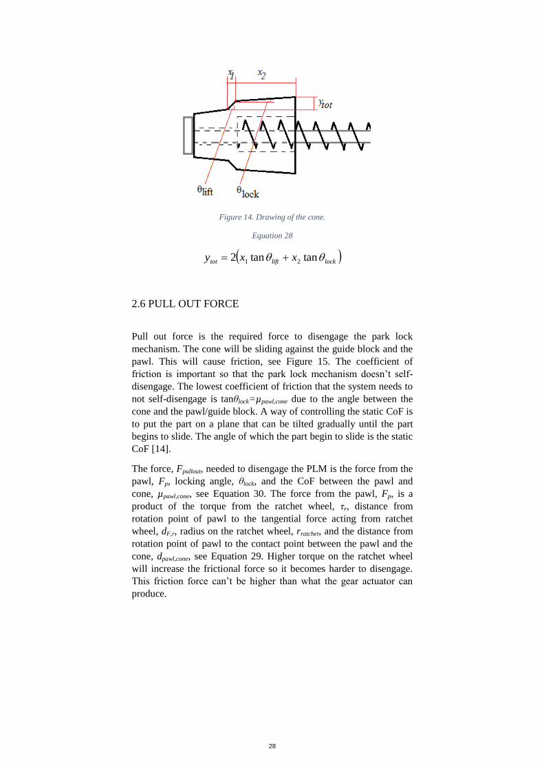
2.5.1 CONE
When the fork, see Figure 1, move horizontal, the cone will lift the
actuator to an angle. The cone will also lift the pawl to an angle. The
total lift of the pawl, ytot, is calculated by knowing the length of
movement, x1, the cone makes while on the lifting angle of the cone,
θlift, the length of movement, x2, during the locking angle of the cone,
θlock, see Equation 28, see Figure 14. The total length of travel for the
cone is the lengths x1 and x2 added to each other.
Page 28
28
Figure 14. Drawing of the cone.
Equation 28
locklifttot xxy tantan2 21
2.6 PULL OUT FORCE
Pull out force is the required force to disengage the park lock
mechanism. The cone will be sliding against the guide block and the
pawl. This will cause friction, see Figure 15. The coefficient of
friction is important so that the park lock mechanism doesn’t self-
disengage. The lowest coefficient of friction that the system needs to
not self-disengage is tanθlock=µpawl,cone due to the angle between the
cone and the pawl/guide block. A way of controlling the static CoF is
to put the part on a plane that can be tilted gradually until the part
begins to slide. The angle of which the part begin to slide is the static
CoF [14].
The force, Fpullout, needed to disengage the PLM is the force from the
pawl, Fp, locking angle, θlock, and the CoF between the pawl and
cone, µpawl,cone, see Equation 30. The force from the pawl, Fp, is a
product of the torque from the ratchet wheel, τr, distance from
rotation point of pawl to the tangential force acting from ratchet
wheel, dF,r, radius on the ratchet wheel, rratchet, and the distance from
rotation point of pawl to the contact point between the pawl and the
cone, dpawl,cone, see Equation 29. Higher torque on the ratchet wheel
will increase the frictional force so it becomes harder to disengage.
This friction force can’t be higher than what the gear actuator can
produce.
Page 29
29
Figure 15. Cross-section figure of the friction force on the pawl (on the top), cone
(in the middle) and guide block (on the bottom).
Equation 29
conepawlratchet
rFr
pdr
dF
,
,
Equation 30
locklock,lock sincoscos2 conepawlppullout FF
2.7 RETURN SPRING
The return spring keeps the pawl from self-engaging due to
accelerations acting on the vehicle e.g. driving over bumps or
potholes. The torque needed from the return spring, τr,s, is calculated
by the inertia of the pawl, Ipawl, maximum acceleration, amax,g, angle
of the pawl, θtan, acting on the pawl and distance from the rotational
point of pawl to its centre of gravity, dpawl,CoG, see Equation 31 and
the system is shown in Figure 16.
Equation 31
CoGpawl
gpawl
srd
aI
,
tanmax,
,
cos
Figure 16. The system exposed by an acceleration.
Page 30
30
3 RESULT
The result is a CAE tool in form of an Excel workbook that will
calculate:
Static torque on ratchet wheel on a slope with or without
trailer.
Dynamic torque on ratchet wheel on 0% grade with or
without trailer.
Snap release torque on ratchet wheel on a slope.
Friction limits between pawl and cone.
Pull out force, uphill and downhill.
Engagement speed.
Rollback.
Release spring.
Actuator spring.
The inputs needed for the calculations:
Mass of vehicle.
Mass of wheel.
Mass of pawl.
Mass of trailer.
Radius of tire.
Radius of pawl contact point downhill.
Radius of pawl contact point uphill.
Radius of pawl centre of gravity.
Radius of pawl centre of cone.
Radius of the ratchet wheel.
Lever for force on pawl from static force from the ratchet
wheel.
Gear ratio on final drive.
Gravitational acceleration.
Slope gradient.
Number of teeth on ratchet wheel.
CoF between pawl and cone.
Coefficient of rolling resistance.
Angle of the cone locking.
Angle of the cone lifting.
Angle of the pawl traveling from disengaged to engaged.
Angle of the ratchet wheel traveling from uphill to downhill.
Angle of the pawl to the horizontal line.
Angle of pawl travelling before hitting the ratchet wheel
tooth.
Angle of release spring preloaded.
Angle of release spring engaged.
Page 31
31
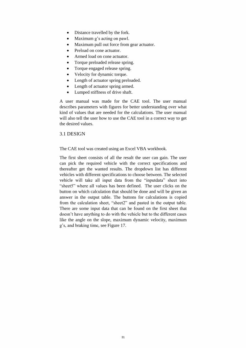
Distance travelled by the fork.
Maximum g’s acting on pawl.
Maximum pull out force from gear actuator.
Preload on cone actuator.
Armed load on cone actuator.
Torque preloaded release spring.
Torque engaged release spring.
Velocity for dynamic torque.
Length of actuator spring preloaded.
Length of actuator spring armed.
Lumped stiffness of drive shaft.
A user manual was made for the CAE tool. The user manual
describes parameters with figures for better understanding over what
kind of values that are needed for the calculations. The user manual
will also tell the user how to use the CAE tool in a correct way to get
the desired values.
3.1 DESIGN
The CAE tool was created using an Excel VBA workbook.
The first sheet consists of all the result the user can gain. The user
can pick the required vehicle with the correct specifications and
thereafter get the wanted results. The dropdown list has different
vehicles with different specifications to choose between. The selected
vehicle will take all input data from the “inputdata” sheet into
“sheet5” where all values has been defined. The user clicks on the
button on which calculation that should be done and will be given an
answer in the output table. The buttons for calculations is copied
from the calculation sheet, “sheet2” and pasted in the output table.
There are some input data that can be found on the first sheet that
doesn’t have anything to do with the vehicle but to the different cases
like the angle on the slope, maximum dynamic velocity, maximum
g’s, and braking time, see Figure 17.
Page 32
32
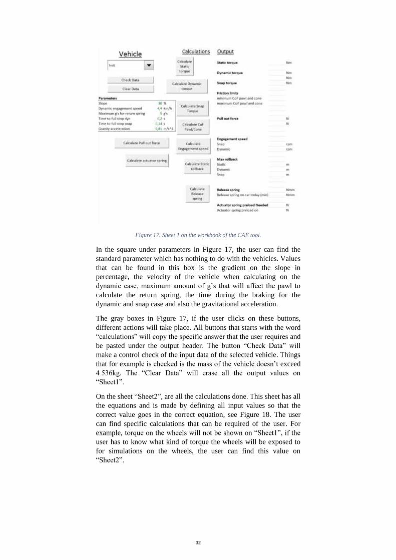
Figure 17. Sheet 1 on the workbook of the CAE tool.
In the square under parameters in Figure 17, the user can find the
standard parameter which has nothing to do with the vehicles. Values
that can be found in this box is the gradient on the slope in
percentage, the velocity of the vehicle when calculating on the
dynamic case, maximum amount of g’s that will affect the pawl to
calculate the return spring, the time during the braking for the
dynamic and snap case and also the gravitational acceleration.
The gray boxes in Figure 17, if the user clicks on these buttons,
different actions will take place. All buttons that starts with the word
“calculations” will copy the specific answer that the user requires and
be pasted under the output header. The button “Check Data” will
make a control check of the input data of the selected vehicle. Things
that for example is checked is the mass of the vehicle doesn’t exceed
4 536kg. The “Clear Data” will erase all the output values on
“Sheet1”.
On the sheet “Sheet2”, are all the calculations done. This sheet has all
the equations and is made by defining all input values so that the
correct value goes in the correct equation, see Figure 18. The user
can find specific calculations that can be required of the user. For
example, torque on the wheels will not be shown on “Sheet1”, if the
user has to know what kind of torque the wheels will be exposed to
for simulations on the wheels, the user can find this value on
“Sheet2”.
Page 33
33
Figure 18. Sheet 2 has all the equations and calculations.
The sheet “inputdata” is for storing all the input information about
the vehicles. Here the user can fill in new vehicles and give them new
values. This is where the dropdown list from the first sheet gets all
the information, see Figure 19. Values that will be needed is listed in
3 RESULT. The values in Figure 19 are made up and are not from
real vehicles.
Figure 19. Sheet inputdata gather all the technical specification about the vehicle.
Page 34
34
The last sheet is the input sheet. On this sheet, all the values are
defined. The dropdown list on the first sheet picks a vehicle and that
vehicles input information is put in this sheet. So that the values can
be defined and be used in the equations, see Figure 20.
Figure 20. All values from the chosen vehicle are defined.
Page 35
35
4 DISCUSSION
4.1 GENERAL DISCUSSION
When comparing the values from the CAE tool to the values from
previous reports [16, 17] that other companies have done they aren’t
always the same. The values between the companies can also vary
which indicates that they use different equations or neglect some
values e.g. the dynamic torque case when both Vicura and PUNCH
has the same input the result differs by 0,4%. For the calculations on
the preload force needed from the actuator spring the values differs
by 34% between Vicura and the CAE tool.
The actuator rod in this design will be tilted 2° when engaged due to
the cone that slides against the guiding block making the locking
angle slight different from the calculated case. This makes the
locking angle on the pawl side 2° less and 2° more on the guide block
side. This will not affect the pull out force much because of what it
loses in friction force on the guide block it gains on the pawl side.
The CAE tool doesn’t consider this problem. The two CoF must be
summed up and the average of them will show the CoF needed as
minimum.
Equation 32
2tan
2
tantan 2121
The torque on the ratchet wheel is a product of friction force between
the road and the tire, lever as the radius of the tire and the gear ratio.
The friction force that contributes to the torque on the wheels is never
calculated with the normal force times the coefficient of friction. It is
instead calculated with the needed force to stop the vehicle in a
certain time to get the worst load case. The CAE tool will often give
a higher torque value than the values that will come from test results.
The conditions on the road when the vehicle has been tested can
change, all from dirt on the road, bad tires and different weight
distribution of the vehicle. The stopping time that is used in the
calculations is taken from these tests and may not give an accurate
results from an ideal case. The stopping time from test result can also
differs if the vehicle is going uphill or downhill. For example, the
vehicle has the PLM on the front wheels and the vehicle is facing
downhill, it will stop sooner than uphill. The tires slides more when
the vehicle rolling back when uphill. This can be due to the
suspension of the vehicle. The suspension is neglected in the CAE
tool and is calculated as a stiff box. When the vehicle got suspension,
the rotational momentum of the vehicle will be downhill and will
Page 36
36
increase the normal force on the wheels downhill and if the vehicle
has the PLM on that side the ratchet wheel will experience more
torque due to increase friction force and less sliding.
All the calculations are done with a hundred percentage of efficiency
in the system (ideal case). There is some losses in the transmission
like between gears in form of sound, vibrations and heat. There is
also no slip between the tire and the surface in the calculations. In
tests with the nose uphill and the snap release case, the vehicle
usually slips for a couple of centimetre before coming to a full stop.
Therefore, the time for the braking acceleration used in the
calculations, is not always correct.
4.2 DESIGN DISCUSSION
The tool will calculate the torque for the static, dynamic and snap
case for any kind of vehicle with an automatic transmission, because
the torque is calculated to the output shaft which the PLM is located
and has nothing to do with the design the PLM. The friction limits
calculation consider the angle of which locks the pawl in to engaged
mode. The friction then depends on the angle and the tool would only
calculate the friction if there is a locking angle involved. There may
be some design on a PLM that doesn’t use a locking angle and have
another solution to the problem.
The engagement speed can be implemented on every vehicle with the
DCT. This calculates the angular velocity of the ratchet wheel when
the maximum velocity of the vehicle is reached and it still will be
able to get the pawl into engage mode. The rollback calculation apply
for most vehicle with a DCT. The rollback calculations depends on
the design of the ratchet wheel, final drive gear ratio and the tire
radius. This solution is common among the DCT vehicles. There can
be other solutions to lock the wheel and there can still be rollback,
the user must therefore define the way it is designed to calculate the
rollback using the tool. The release spring is only able to be
calculated if the pawl is rotated. The release spring is a torsion spring
and will give torque to the pawl to not jump into engaged position if
the vehicle will be exposed of acceleration, like going over a pothole.
The same accounts for the actuator spring. This design must be a
straight spring with a cone that has a lifting angle, a locking angle so
that the pawl can be lifted and locked safely without fail to fit the
CAE tool.
The CAE tool has a lot of assumptions and simplifications to make
the tool more universal. The CAE tool doesn’t consider if the
construction has a loose fit, therefore consideration has to be done
when making real time tests and also when designing the part. The
cone and the actuator rod is one example of loose fit. This can
increase the friction force between the two parts and load the rod
Page 37
37
with high contact forces. This case mostly happens when the pawl
shall disengage when the cone has a lot of force on it.
The calculations using the dimension of the cone is restricted to the
design of the cone. The cone used in the tool has two angles and two
lengths. If a new design is taken, the equation must be changed to
consider the new design.
The calculation of the actuator spring is calculated by average force
and acceleration. In the real case the acceleration of the pawl take
place in two parts. First is the part when the cone is lifting the pawl
with the lifting angle of the cone, double the distance in y-direction
than the cone is moving the cone in x-direction and second part is the
locking angle of the cone which lifts the pawl only a little. This
makes the acceleration on the pawl high in the beginning and after
the lifting angle a smaller acceleration.
The acceleration on the pawl is calculated into one tangential force,
see Figure 21, but in real case the force will look more like the force
is in the y-direction all the time. This will make a small error on the
actuator spring calculation. But because of that the pawl is only
moving ~6,5°, the correction is neglected.
Figure 21. Tangential force action on a rotational arm.
The friction between the pawl and the cone when the cone is
engaging the pawl is neglected due to its small contribution for the
actuator spring calculation. The CoF is small to begin with, it’s
between 0,08 to 0,18, and this is for a wet gear box [17]. The normal
force on the cone is whatever the pawl is contributing with and it’s
some of the weight of the pawl and the return spring. This will not
give a significant value to the actuator spring.
The value for the actuator spring is the mean amount of force the
spring must execute. The spring force changes with the compression
with the spring. The user can use the value as the preload but if the
spring coefficient is known a smaller compression can be used and
still execute the engagement of the pawl.
Page 38
38
4.3 FUTURE WORK
The CAE tool could have more functions and equations to make it a
handier tool. The tool should include weight distribution for more
exact values like them form a real life test. The tool should also
consider the condition of the road because of that the torque on the
wheel comes from the friction force between the road and the tire of
the vehicle. If the user can choose the tire that is used and on what
kind of surface it will be tested on, the results would be more
accurate.
More work can be done on the design of this tool to make it easier to
use for anyone and to understand how it works.
If the tool could import data directly from CAD files to get input data
for the calculations, it would be a major help for the tool to work
smooth and fast.
Because of that the pawl should always jump out of parked position
when the PLM is disengaged, there should be a function in the tool
that tells the user that it will for sure do that. There should also be
calculations of torque on the pawl acting while it has torque on it
from the ratchet wheel. There can be different values on the CoF
between the pawl and the ratchet wheel making the friction force
differ. If the CoF would be too high or wrongly designed the pawl
could get stuck when high loads acting on the pawl. This must not
happen.
Page 39
39
5 CONCLUSION
According to the goal which is described in section 1.4, the goal was
to create a CAE tool that would give values on the requested output
values for different designs and other specifications on the vehicle.
The method used for the CAE tool was Excel VBA and the design
can be found in section 3.1 DESIGN
The needed input data and the calculated output data was defined in
section 3 RESULT. All the equations for calculate the output data is
found under the section 2 THEORY.
Page 40
40
6 REFERENCE
[1]Federal motor vehicle safety standards and regulations (1999)
Available at:
https://icsw.nhtsa.gov/cars/rules/import/FMVSS/#SN114 (Accessed:
3 February 2017
[2] "Volvo Cars, CEVT And “Platform Thinking” In Automotive
Product Development > ENGINEERING.Com". Engineering.com.
N.p., 2017. Web. 29 Apr. 2017.
[3] "Concept Cars | Volvo Cars". Volvocars.com. N.p., 2017. Web.
28 Apr. 2017.
[4] "Torque Converter, CVT, Dual Or Single Clutch Autos, What's
The Difference?". CarsGuide. N.p., 2017. Web. 2 May 2017.
https://www.carsguide.com.au/car-advice/torque-converter-cvt-dual-
or-single-clutch-autos-whats-the-difference-33411 (2017-05-17)
[5] Works, H.C.A. (2017) How the transmission works. Available at:
https://www.howacarworks.com/basics/how-the-transmission-works
(Accessed: 10 February 2017).
[6] Oh, J.J., Choi, S.B. and Kim, J. (2014) ‘Driveline modeling and
estimation of individual clutch torque during gear shifts for dual
clutch transmission’, Mechatronics, 24(5), pp. 449–463. doi:
10.1016/j.mechatronics.2014.04.005.
[7] Fatima, N., Minami, I., Holmgren, A., Marklund, P. and Larsson,
R. (2016) ‘Surface chemistry of wet clutch influenced by water
contamination in automatic transmission fluids’, Tribology
International, 96, pp. 395–401. doi: 10.1016/j.triboint.2015.04.010.
[8] Jeyakumaran, J. and Zhang, N. (2008) ‘Dynamic analysis of an
automatic transmission parking mechanism’. Available at:
http://epress.lib.uts.edu.au/research/handle/10453/11997http://hdl
(Accessed: 9 February 2017).
[9]Transmission parking Pawl - my AutomaticTransmission.com (no
date) Available at:
http://estimate.myautomatictransmission.com/transmission-parking-
pawl/ (Accessed: 3 February 2017).
[10] Fort, W., Ko, K. and Farmer, W. (2005) Park pawl actuator.
Available at: https://www.google.com/patents/US20050044979
(Accessed: 3 February 2017)
[11] Young, C.J., Fyie, M.L., Devincent, E.J. and Technologies, V.G.
(2000) Patent US6279713 - parking pawl assembly. Available at:
Page 41
41
https://www.google.com/patents/US6279713 (Accessed: 3 February
2017).
[12] Huang, Y. (no date) ‘Park Lock Analysis using
VALDYN’, Ricardo Inc, Advanced Systems Engineering.
(Accessed: 20 February 2017).
[13] Nogle, T.D. and Corporation, D. (1999) Patent US6065581 -
Camming manual lever for pull-out load. Available at:
https://www.google.com/patents/US6065581 (Accessed: 23 February
2017).
[14] Jacobson, S. and Hogmark, S. (1996) Tribologi: Friktion,
smörjning och nötning. 2nd edn. Stockholm: Liber utbildning.
[15] Free, M. (2015) The difference between Ra and Rz. Available at:
http://www.productionmachining.com/blog/post/the-difference-
between-ra-and-rz (Accessed: 20 February 2017).
[16] Farhan Khan, Park Lock Calculation CEVT, Vicura, (2016-08-
30)
[17] Vincent, M., Ebb, C. and Drouet, F. CEVT Park Lock System,
PUNCH powerglide, STC Strasbourg, (2016-10-15)
Page 42
42
7 APPENDICES
7.1 LIST OF FIGURES
Figure 1. Park lock mechanism, (1) ratchet wheel, (2) pawl, (3) shaft,
(4) guide block, (5) cone, (6) actuator spring, (7) actuator rod, (8)
fork, (9) return spring, (10) bracket. ................................................. 11
Figure 2. Schematic picture on rollback on the PLM, both rollaway
when park up the slope and down the slope. .................................... 12
Figure 3. To the left, PLM disengaged. To the right, PLM engaged.12
Figure 4. Schematic figure of reaction forces acting on a vehicle
while in motion. ................................................................................ 14
Figure 5. Reaction forces on a vehicle that stands on a slope. .......... 15
Figure 6. Schematic figure over the torque transfer from wheels to
ratchet wheel. .................................................................................... 16
Figure 7. The angles on the tooth of the ratchet wheel show the non
symetrical geometry. ......................................................................... 17
Figure 8. Torque acting on the wheel. .............................................. 18
Figure 9. Schematic image of vehicle stopping. ............................... 19
Figure 10. Forces acting on the vehicle when snap case. ................. 20
Figure 11. Schematic figure of wear at sliding contact where
adhesive contact bridges are broken through shear fractures in one of
the materials. Typically too heavy (usually non-lubricated) wear of
the metal. ........................................................................................... 23
Figure 12. Schematic figure of ploughing. ....................................... 24
Figure 13. The park lock mechanism with tribological system pointed
out, (1) gear actuator & ground, (2) pawl & bracket, (3) pawl & shaft,
(4) pawl & cone and (5) pawl & ratchet wheel. ................................ 25
Figure 14. Drawing of the cone. ....................................................... 28
Figure 15. Cross-section figure of the friction force on the pawl (on
the top), cone (in the middle) and guide block (on the bottom). ....... 29
Figure 16. The system exposed by an acceleration. .......................... 29
Figure 17. Sheet 1 on the workbook of the CAE tool. ...................... 32
Figure 18. Sheet 2 has all the equations and calculations. ................ 33
Figure 19. Sheet inputdata gather all the technical specification about
the vehicle. ........................................................................................ 33
Figure 20. All values from the chosen vehicle are defined. .............. 34
Figure 21. Tangential force action on a rotational arm. .................... 37