39
ANSYS CFD v14 5 ANSYS CFD v14.5 Update Seminar CAE Associates Inc. and ANSYS Inc. Proprietary © 2013 CAE Associates Inc. and ANSYS Inc. All rights reserved.
| Date post: | 01-Feb-2018 |
| Category: |
Documents |
| Upload: | truongdung |
| View: | 271 times |
| Download: | 1 times |
ANSYS CFD v14 5 ANSYS CFD v14.5
Update Seminarp
CAE Associates Inc. and ANSYS Inc. Proprietary© 2013 CAE Associates Inc. and ANSYS Inc. All rights reserved.
Outline
Design Iteration/Optimization using CFX and DX— Demo
O FSI— One-way FSI
ANSYS Meshing v14 5 ANSYS Meshing v14.5
ANSYS CFX v14.5
ANSYS Fluent v14.5
Shape Optimization using Fluent Adjoint MethodD
2
— Demo
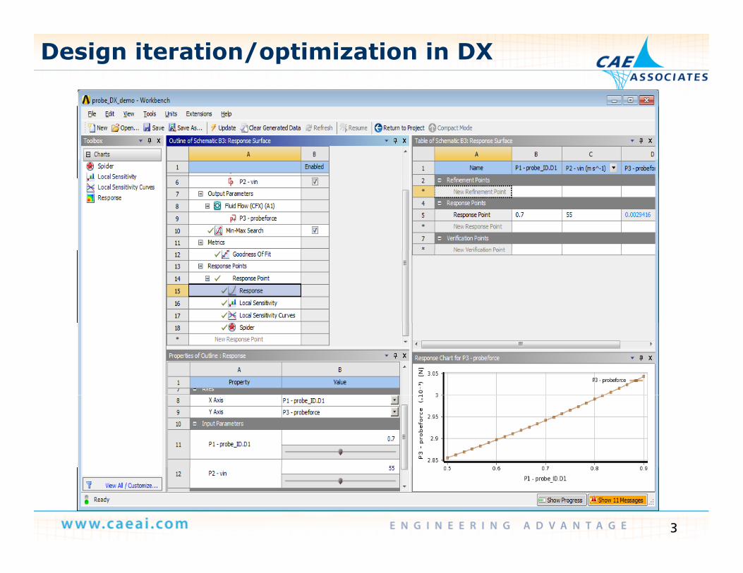
Design iteration/optimization in DX
3
Outline
Design Iteration/Optimization using CFX and DX— Demo
O FSI— One-way FSI
ANSYS Meshing v14 5 ANSYS Meshing v14.5
ANSYS CFX v14.5
ANSYS Fluent v14.5
Shape Optimization using Fluent Adjoint MethodD
4
— Demo
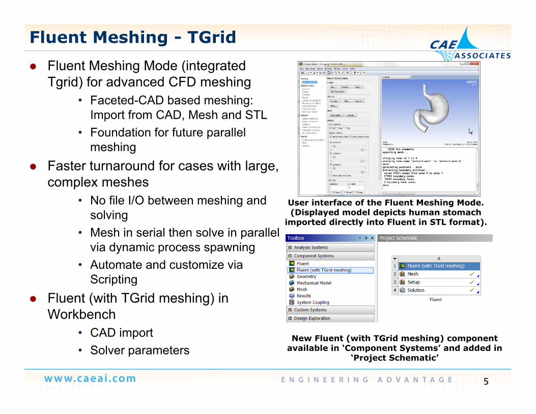
Fluent Meshing - TGrid Fluent Meshing Mode (integrated
) f CTgrid) for advanced CFD meshing• Faceted-CAD based meshing:
Import from CAD, Mesh and STLF d ti f f t ll l• Foundation for future parallel meshing
Faster turnaround for cases with large, complex meshescomplex meshes
• No file I/O between meshing and solving
• Mesh in serial then solve in parallel
User interface of the Fluent Meshing Mode. (Displayed model depicts human stomach
imported directly into Fluent in STL format). • Mesh in serial then solve in parallel
via dynamic process spawning• Automate and customize via
Scriptingp g Fluent (with TGrid meshing) in
Workbench• CAD import New Fluent (with TGrid meshing) component
5
p• Solver parameters
New Fluent (with TGrid meshing) component available in ‘Component Systems’ and added in
‘Project Schematic’
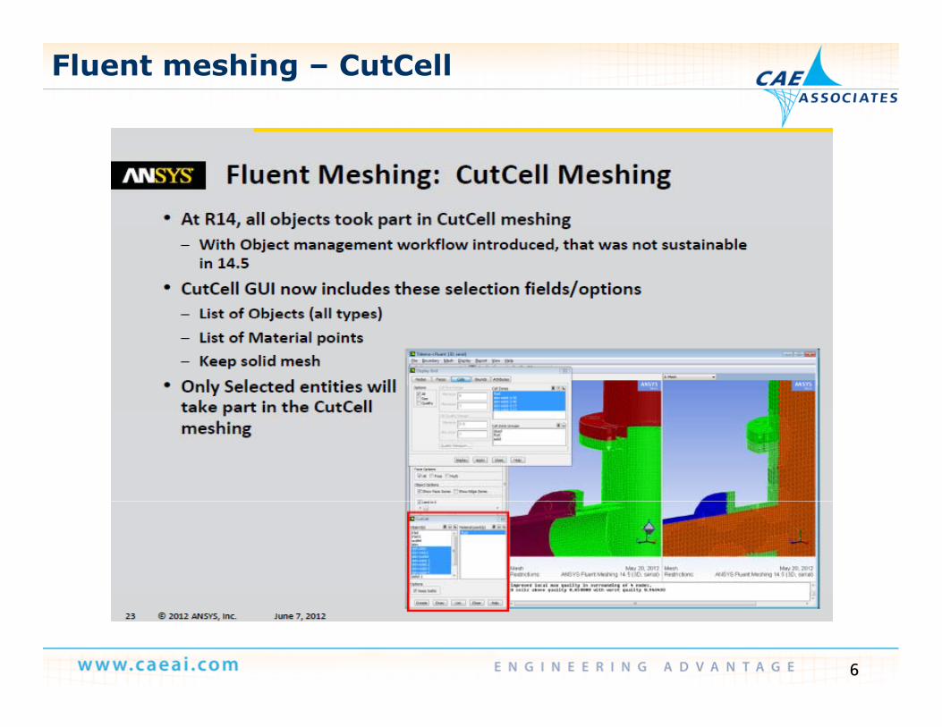
Fluent meshing – CutCell
6
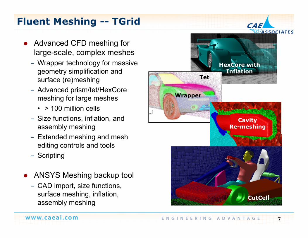
Advanced CFD meshing for
Fluent Meshing -- TGrid
Advanced CFD meshing for large-scale, complex meshes
– Wrapper technology for massive geometry simplification and
HexCore with Inflationg y p
surface (re)meshing– Advanced prism/tet/HexCore
meshing for large meshes Wrapper
Tet
• > 100 million cells– Size functions, inflation, and
assembly meshingCavity
Re-meshingCavity
Re-meshingCavity
Re-meshing
– Extended meshing and mesh editing controls and tools
– Scripting
ANSYS Meshing backup tool– CAD import, size functions,
surface meshing inflation
7
surface meshing, inflation, assembly meshing
CutCell
How can Fluent Meshing extend WB Meshing?
● Workbench Meshing is the proposed meshing solution, Fluent Meshing is a complement. With Workbench Meshing, you have ease-of-use, parametric and persistence throughout the meshing , p p g gprocess. But if the time/quality does not meet client needs for a specific model, Fluent Meshing could be your back-up solution.
● Note that geometry/mesh changes are not parametric with Fluent Meshing, except using advanced scripting
● Fluent Meshing has extended capabilities to produce high quality meshes
● Fluent Meshing is directly available to all Fluent users without any additional cost or licenses
8
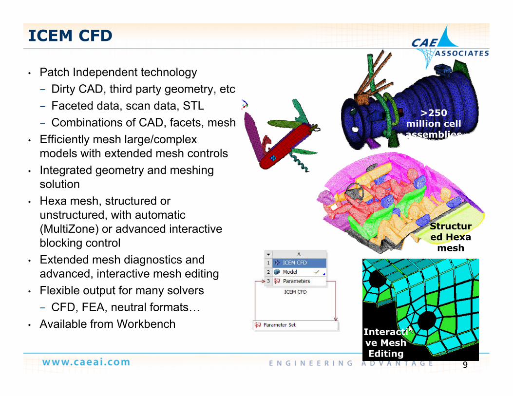
• Patch Independent technology
ICEM CFD
• Patch Independent technology– Dirty CAD, third party geometry, etc– Faceted data, scan data, STL– Combinations of CAD facets mesh
>250 million cell – Combinations of CAD, facets, mesh
• Efficiently mesh large/complex models with extended mesh controls
• Integrated geometry and meshing
million cell assemblies
Integrated geometry and meshing solution
• Hexa mesh, structured or unstructured, with automatic
St t(MultiZone) or advanced interactive blocking control
• Extended mesh diagnostics and advanced interactive mesh editing
Structured Hexa
mesh
advanced, interactive mesh editing• Flexible output for many solvers
– CFD, FEA, neutral formats…Available from Workbench
9
• Available from WorkbenchInteractive Mesh Editing
Interactive Mesh Editing
Interactive Mesh Editing
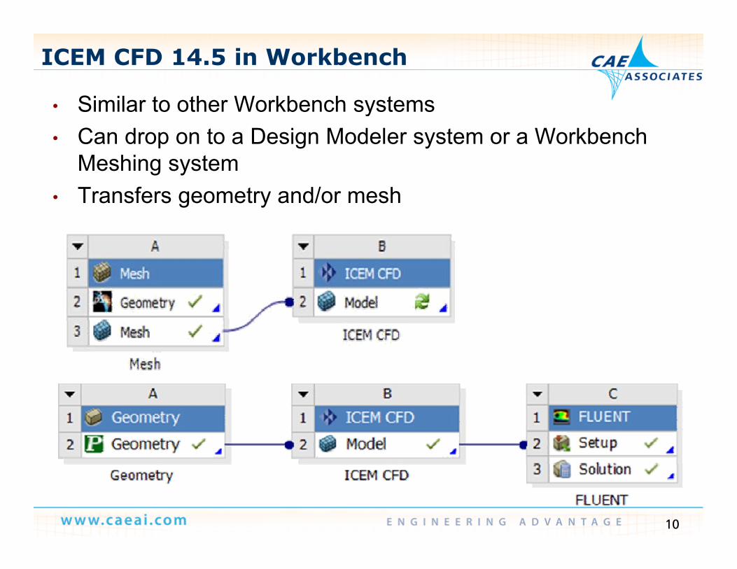
• Similar to other Workbench systems
ICEM CFD 14.5 in Workbench
• Similar to other Workbench systems• Can drop on to a Design Modeler system or a Workbench
Meshing system• Transfers geometry and/or mesh
10
Outline
Design Iteration/Optimization using CFX and DX— Demo— One-way FSI
ANSYS Meshing v14 5 ANSYS Meshing v14.5
ANSYS CFX v14.5ANSYS CFX v14.5
ANSYS Fluent v14.5
Shape Optimization using Fluent Adjoint Method
11
— Demo
Mesh Motion Constrained Parallel to Boundary
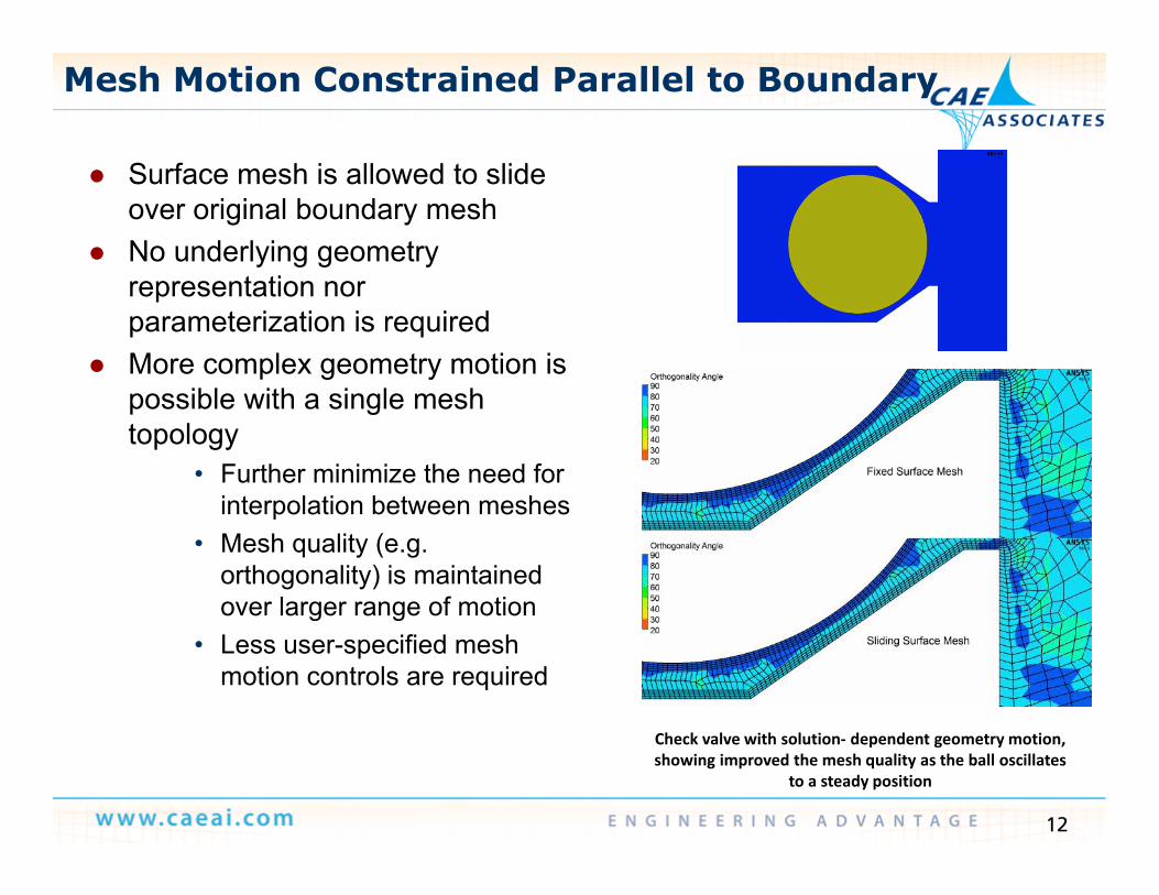
S f h i ll d t lid Surface mesh is allowed to slide over original boundary mesh
No underlying geometry t tirepresentation nor
parameterization is required More complex geometry motion is
ibl ith i l hpossible with a single mesh topology
• Further minimize the need for interpolation between meshesinterpolation between meshes
• Mesh quality (e.g. orthogonality) is maintained over larger range of motiong g
• Less user-specified mesh motion controls are required
12
Check valve with solution‐ dependent geometry motion, showing improved the mesh quality as the ball oscillates
to a steady position
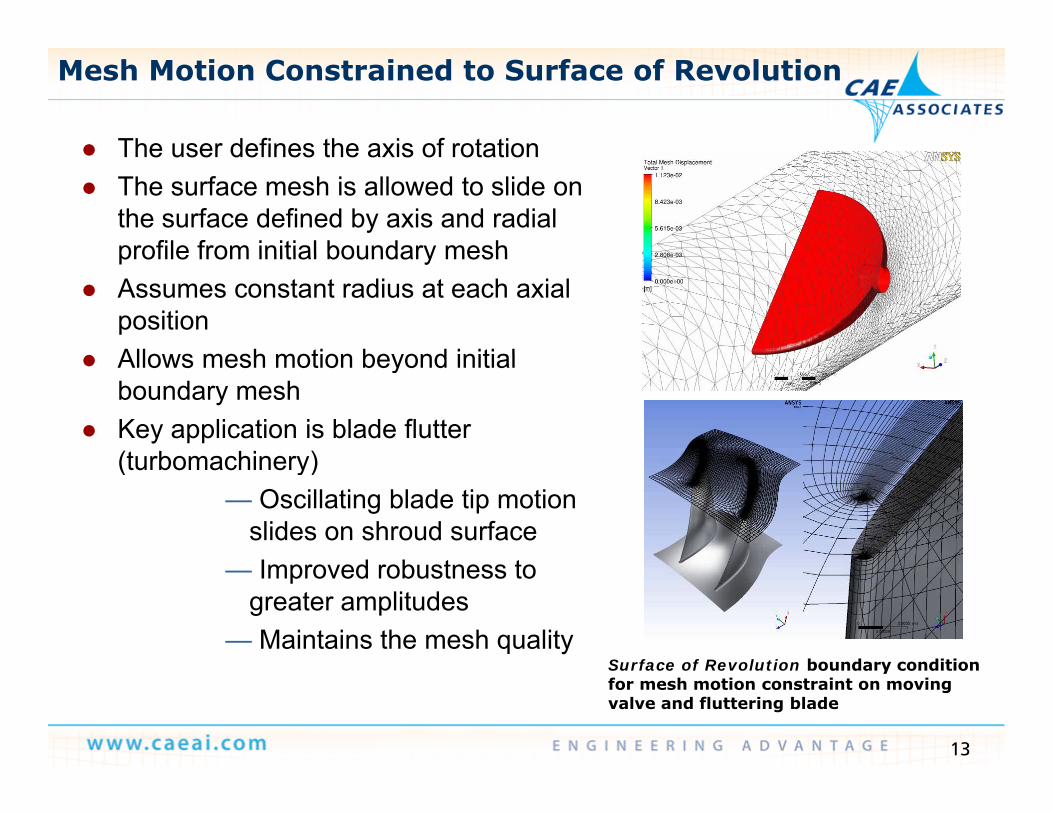
Mesh Motion Constrained to Surface of Revolution
The user defines the axis of rotation The user defines the axis of rotation The surface mesh is allowed to slide on
the surface defined by axis and radial profile from initial boundary meshprofile from initial boundary mesh
Assumes constant radius at each axial position
Allows mesh motion beyond initial Allows mesh motion beyond initial boundary mesh
Key application is blade flutter (turbomachinery)(turbomachinery)
— Oscillating blade tip motion slides on shroud surfaceI d b t t— Improved robustness to
greater amplitudes— Maintains the mesh quality
Surface of Revolution boundary condition
13
Surface of Revolution boundary condition for mesh motion constraint on moving valve and fluttering blade
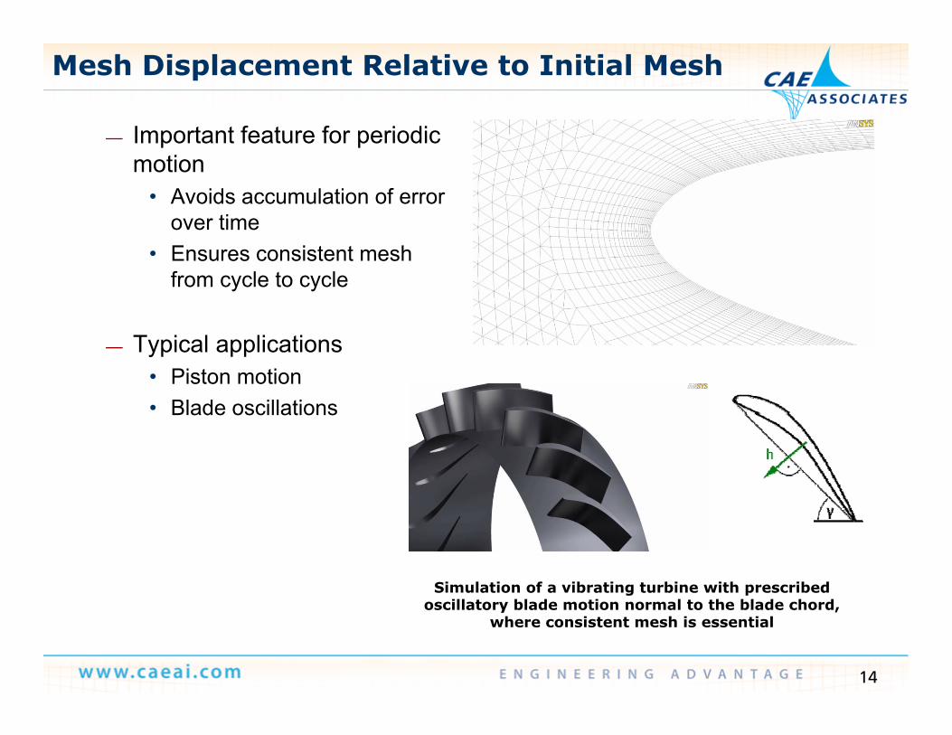
Mesh Displacement Relative to Initial Mesh
Important feature for periodic— Important feature for periodic motion
• Avoids accumulation of error over timeover time
• Ensures consistent mesh from cycle to cycle
— Typical applications• Piston motion• Blade oscillationsBlade oscillations
Simulation of a vibrating turbine with prescribed ill bl d i l h bl d h d
14
oscillatory blade motion normal to the blade chord, where consistent mesh is essential
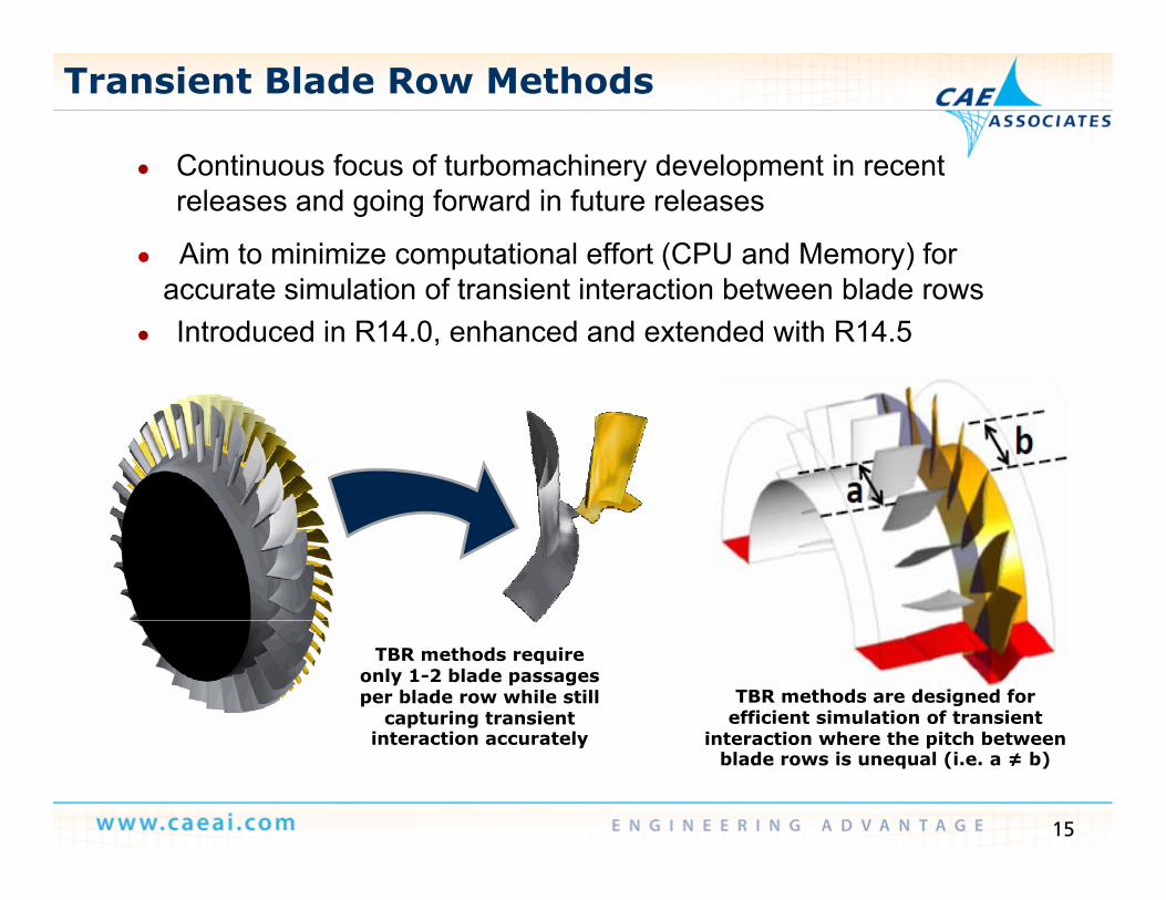
Transient Blade Row Methods
● Continuous focus of turbomachinery development in recent● Continuous focus of turbomachinery development in recent releases and going forward in future releases
● Aim to minimize computational effort (CPU and Memory) for t i l ti f t i t i t ti b t bl daccurate simulation of transient interaction between blade rows
● Introduced in R14.0, enhanced and extended with R14.5
TBR methods require only 1-2 blade passages per blade row while still
capturing transient i t ti t l
TBR methods are designed for efficient simulation of transient
i t ti h th it h b t
15
interaction accurately interaction where the pitch between blade rows is unequal (i.e. a ≠ b)
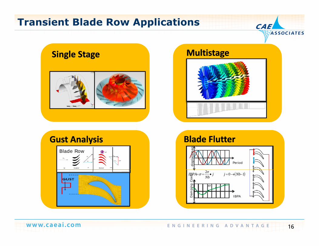
Transient Blade Row Applications
Single StageSingle StageSingle StageSingle Stage MultistageMultistageMultistageMultistage
Blade FlutterBlade FlutterBlade FlutterBlade FlutterGust AnalysisGust AnalysisGust AnalysisGust Analysis Blade FlutterBlade Flutter
PeriodPeriod
disp
lace
men
tdi
spla
cem
ent
Blade FlutterBlade Flutter
Period
disp
lace
men
t
Gust AnalysisGust AnalysisBlade Row
Gust AnalysisGust AnalysisBlade Row
IBPAIBPADam
ping
Coe
f.D
ampi
ng C
oef. 102
NbjjNb
IBPA
IBPADam
ping
Coe
f.
16
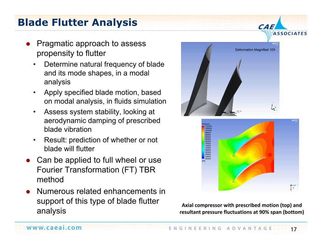
Blade Flutter Analysis
Pragmatic approach to assessPragmatic approach to assess propensity to flutter
• Determine natural frequency of blade and its mode shapes, in a modal analysis
• Apply specified blade motion, based on modal analysis, in fluids simulation
• Assess system stability, looking at aerodynamic damping of prescribed blade vibration
• Result: prediction of whether or not• Result: prediction of whether or not blade will flutter
Can be applied to full wheel or use Fourier Transformation (FT) TBRFourier Transformation (FT) TBR method
Numerous related enhancements in support of this type of blade flutter l h b d ( ) d
17
support of this type of blade flutter analysis
Axial compressor with prescribed motion (top) and resultant pressure fluctuations at 90% span (bottom)
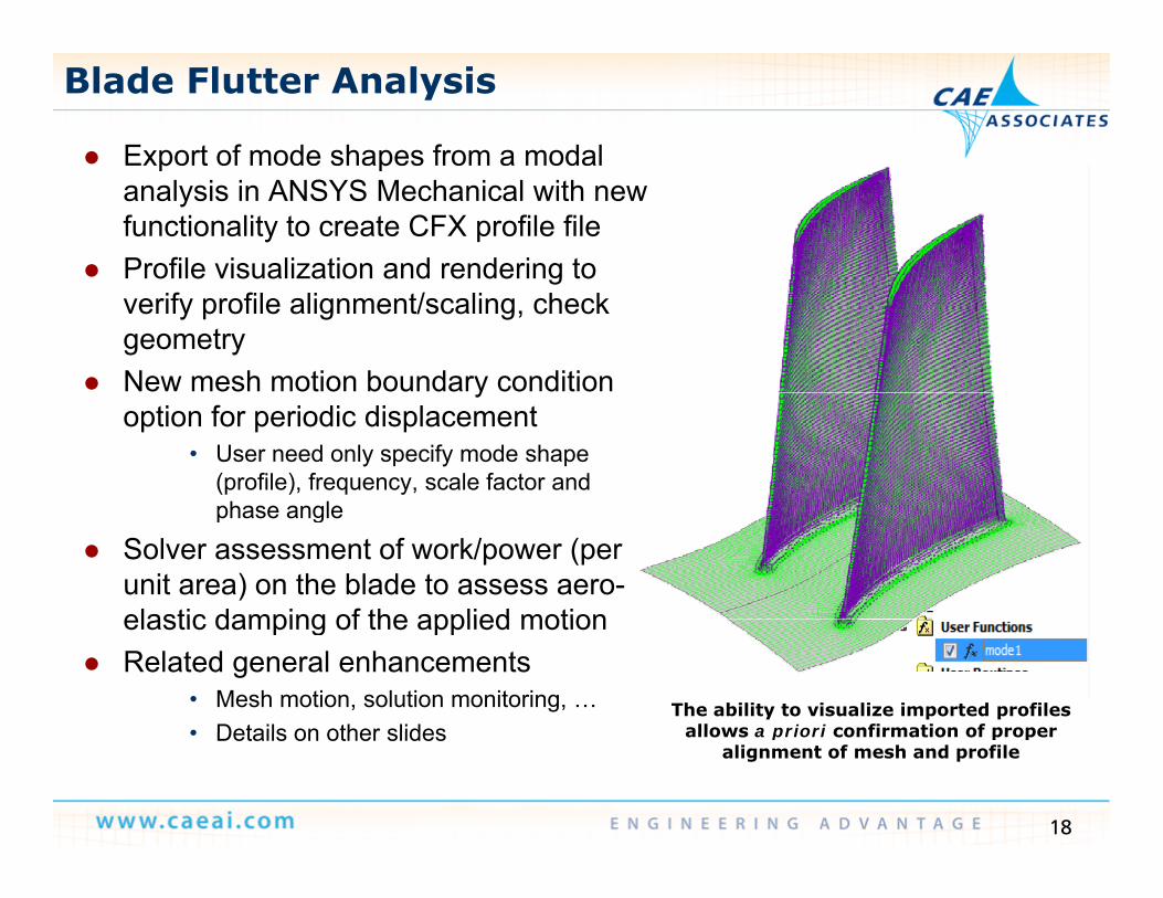
Blade Flutter Analysis
Export of mode shapes from a modal p panalysis in ANSYS Mechanical with new functionality to create CFX profile file
Profile visualization and rendering to gverify profile alignment/scaling, check geometry
New mesh motion boundary condition yoption for periodic displacement
• User need only specify mode shape (profile), frequency, scale factor and phase anglephase angle
Solver assessment of work/power (per unit area) on the blade to assess aero-elastic damping of the applied motionelastic damping of the applied motion
Related general enhancements• Mesh motion, solution monitoring, …• Details on other slides
The ability to visualize imported profiles allows a priori confirmation of proper
18
• Details on other slides allows a priori confirmation of proper alignment of mesh and profile
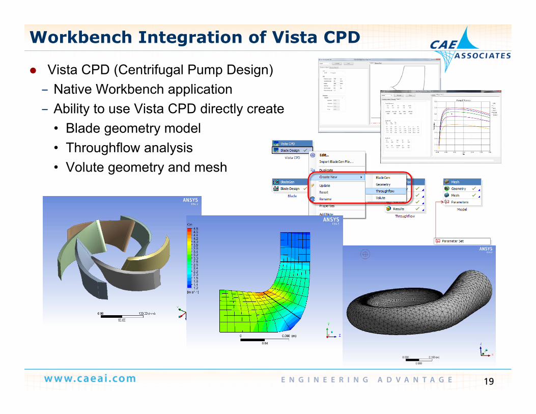
Vista CPD (Centrifugal Pump Design)
Workbench Integration of Vista CPD
( g p g )– Native Workbench application– Ability to use Vista CPD directly create
• Blade geometry model• Blade geometry model• Throughflow analysis • Volute geometry and mesh
19
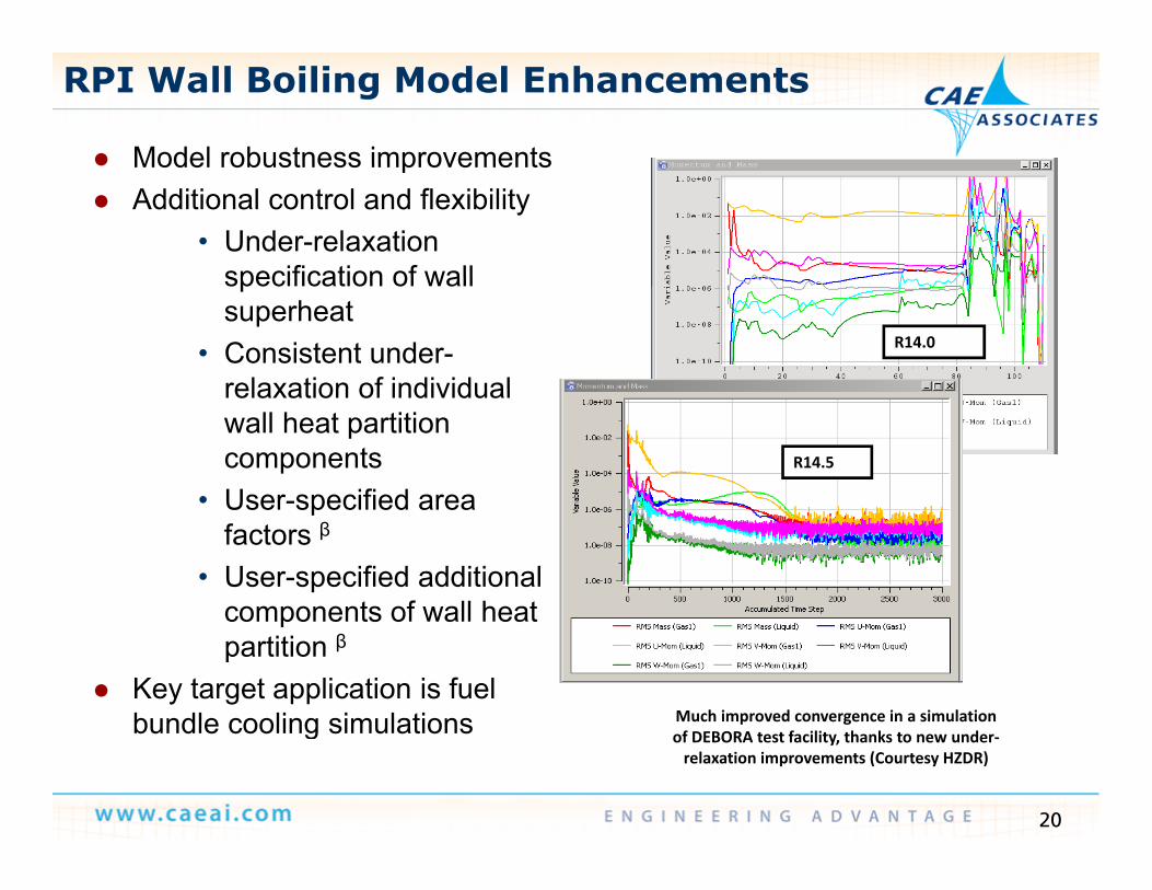
RPI Wall Boiling Model Enhancements
Model robustness improvements Model robustness improvements Additional control and flexibility
• Under-relaxation specification of wallspecification of wall superheat
• Consistent under-relaxation of individual
R14.0
relaxation of individual wall heat partition components
• User-specified areaR14.5
• User-specified area factors β
• User-specified additional components of wall heatcomponents of wall heat partition β
Key target application is fuel bundle cooling simulations Much improved convergence in a simulation
20
bundle cooling simulations of DEBORA test facility, thanks to new under‐relaxation improvements (Courtesy HZDR)
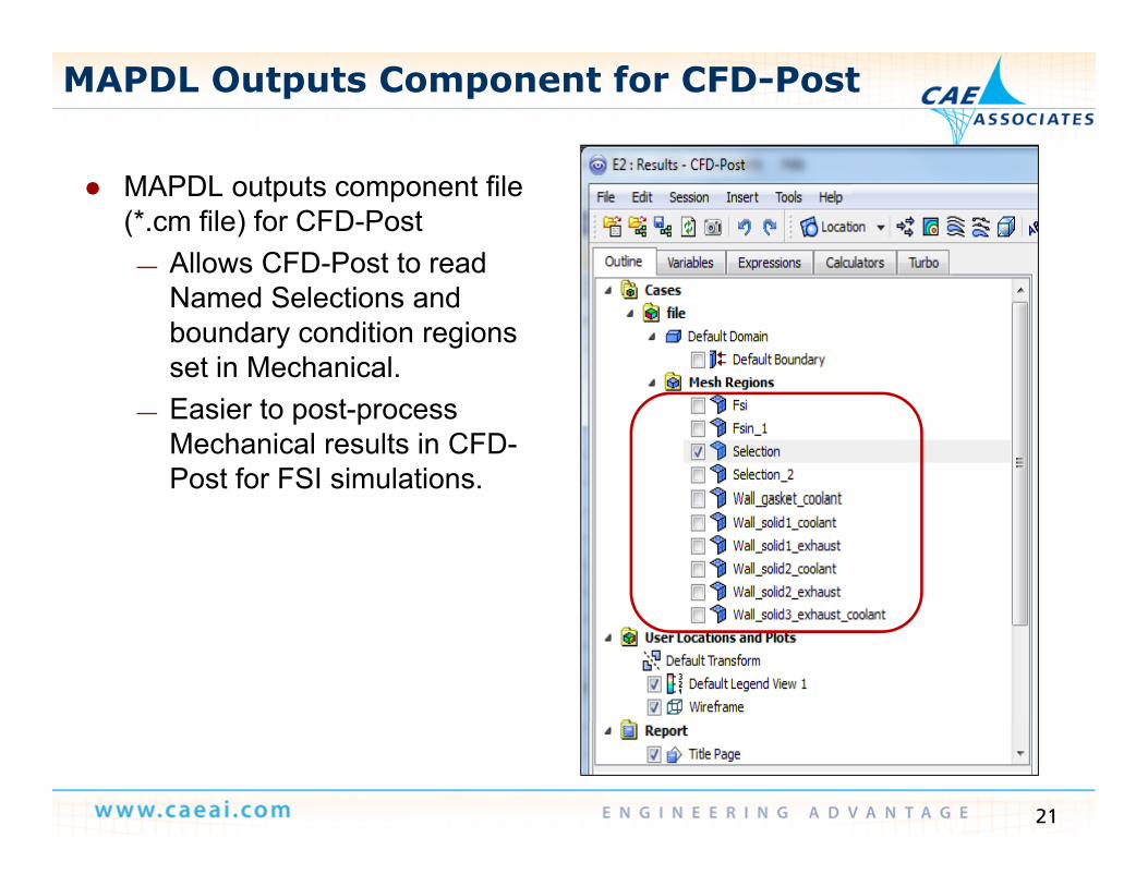
MAPDL Outputs Component for CFD-Post
MAPDL outputs component file (*.cm file) for CFD-Post
— Allows CFD-Post to read Named Selections and boundary condition regions set in Mechanical.
— Easier to post-process Mechanical results in CFD-Post for FSI simulations.
21
Outline
Design Iteration/Optimization using CFX and DX— Demo— One-way FSI
ANSYS Meshing v14 5 ANSYS Meshing v14.5
ANSYS CFX v14 5 ANSYS CFX v14.5
ANSYS Fluent v14.5
Shape Optimization using Fluent Adjoint Method
22
— Demo
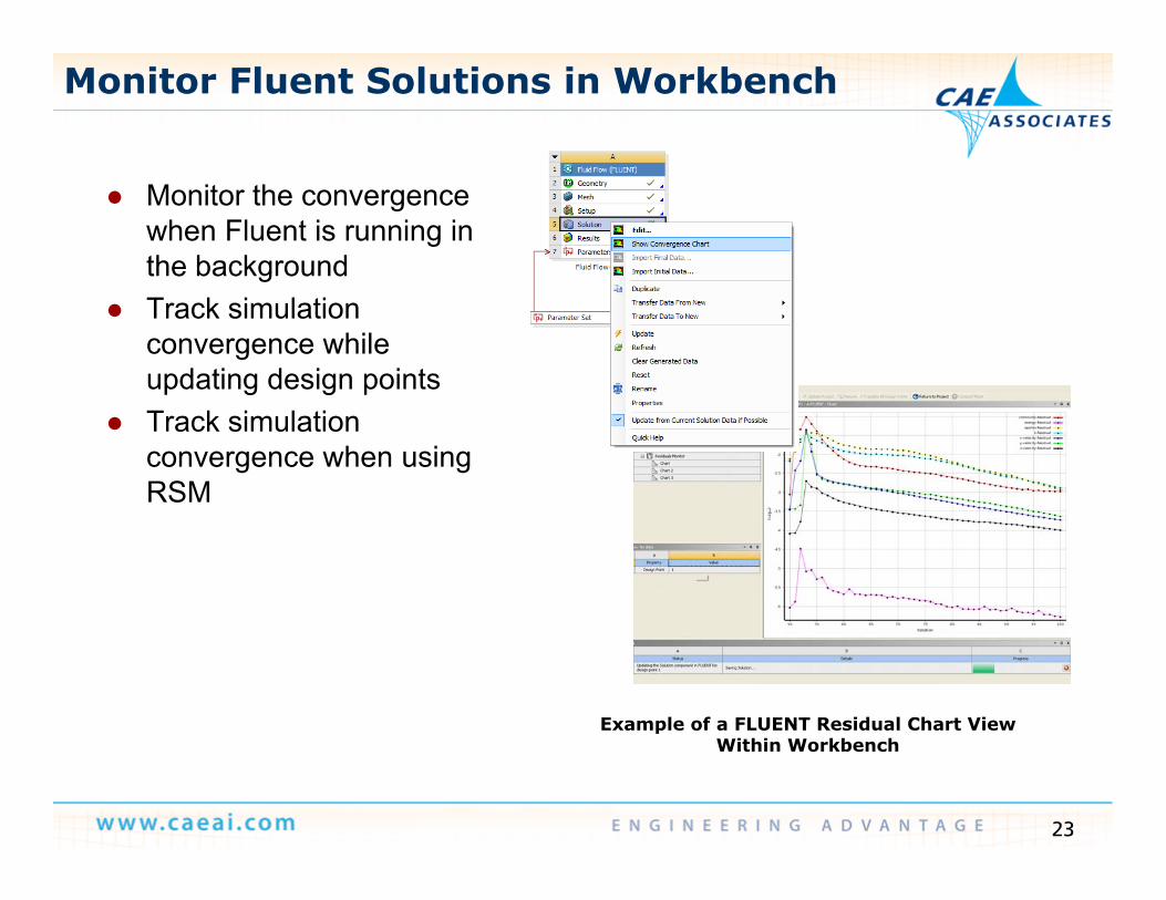
Monitor Fluent Solutions in Workbench
Monitor the convergence when Fluent is running in the backgroundg
Track simulation convergence while updating design pointsp g g p
Track simulation convergence when using RSM
Example of a FLUENT Residual Chart View
23
Within Workbench
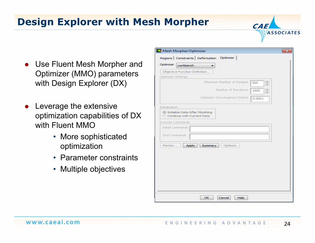
Design Explorer with Mesh Morpher
Use Fluent Mesh Morpher and Optimizer (MMO) parametersOptimizer (MMO) parameters with Design Explorer (DX)
Leverage the extensive Leverage the extensive optimization capabilities of DX with Fluent MMO
• More sophisticated• More sophisticated optimization
• Parameter constraintsM ltiple objecti es• Multiple objectives
24
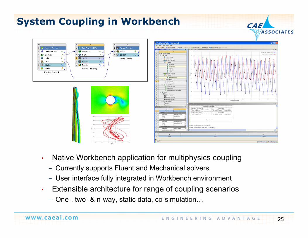
System Coupling in Workbench
• Native Workbench application for multiphysics coupling– Currently supports Fluent and Mechanical solvers– User interface fully integrated in Workbench environment
• Extensible architecture for range of coupling scenarios
25
– One-, two- & n-way, static data, co-simulation…
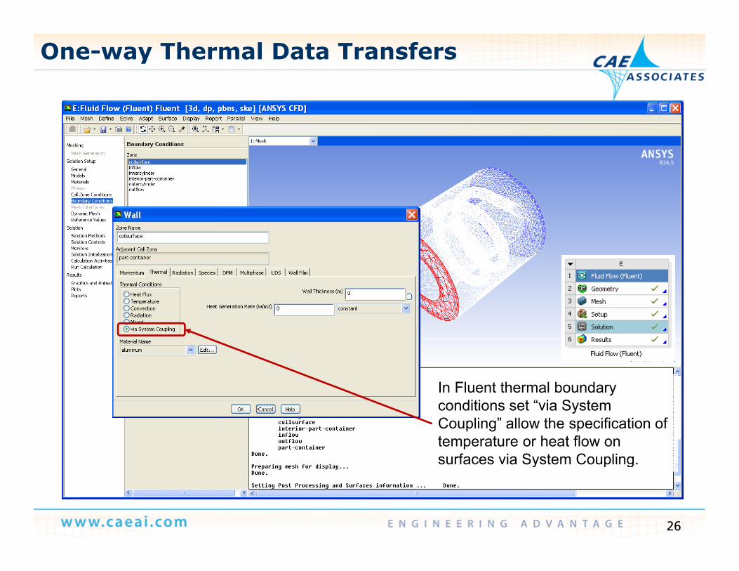
One-way Thermal Data Transfers
In Fluent thermal boundary yconditions set “via System Coupling” allow the specification of temperature or heat flow on surfaces via System Coupling.
26
y p g
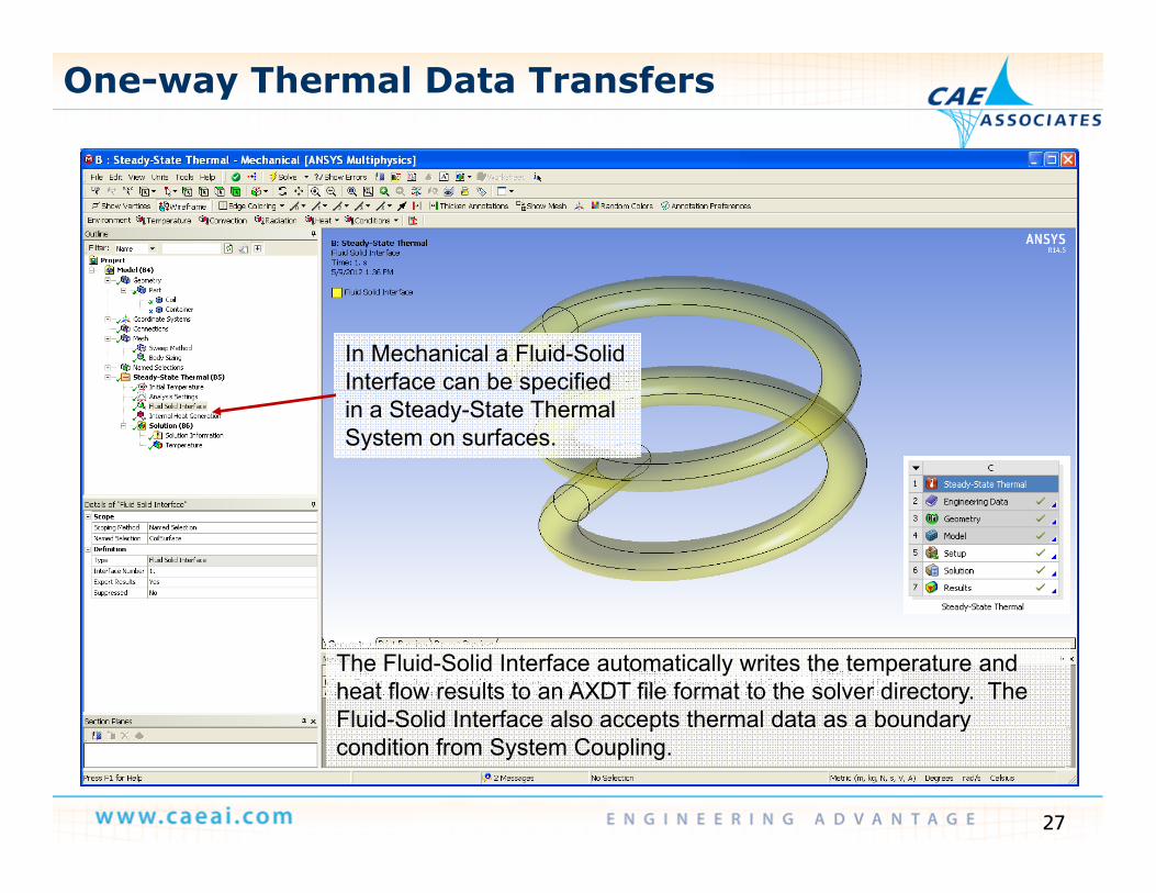
One-way Thermal Data Transfers
In Mechanical a Fluid-Solid Interface can be specified pin a Steady-State Thermal System on surfaces.
The Fluid-Solid Interface automatically writes the temperature and heat flow results to an AXDT file format to the solver directory. The Fluid-Solid Interface also accepts thermal data as a boundary
27
p ycondition from System Coupling.
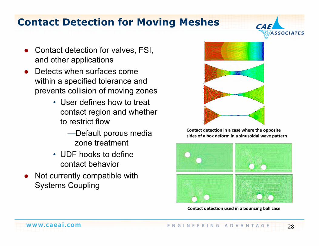
Contact Detection for Moving Meshes
Contact detection for valves, FSI, and other applications
Detects when surfaces come within a specified tolerance and prevents collision of moving zones
• User defines how to treat contact region and whether to restrict flow
—Default porous media Contact detection in a case where the opposite sides of a box deform in a sinusoidal wave pattern
zone treatment• UDF hooks to define
contact behavior Not currently compatible with
Systems Coupling
28
Contact detection used in a bouncing ball case
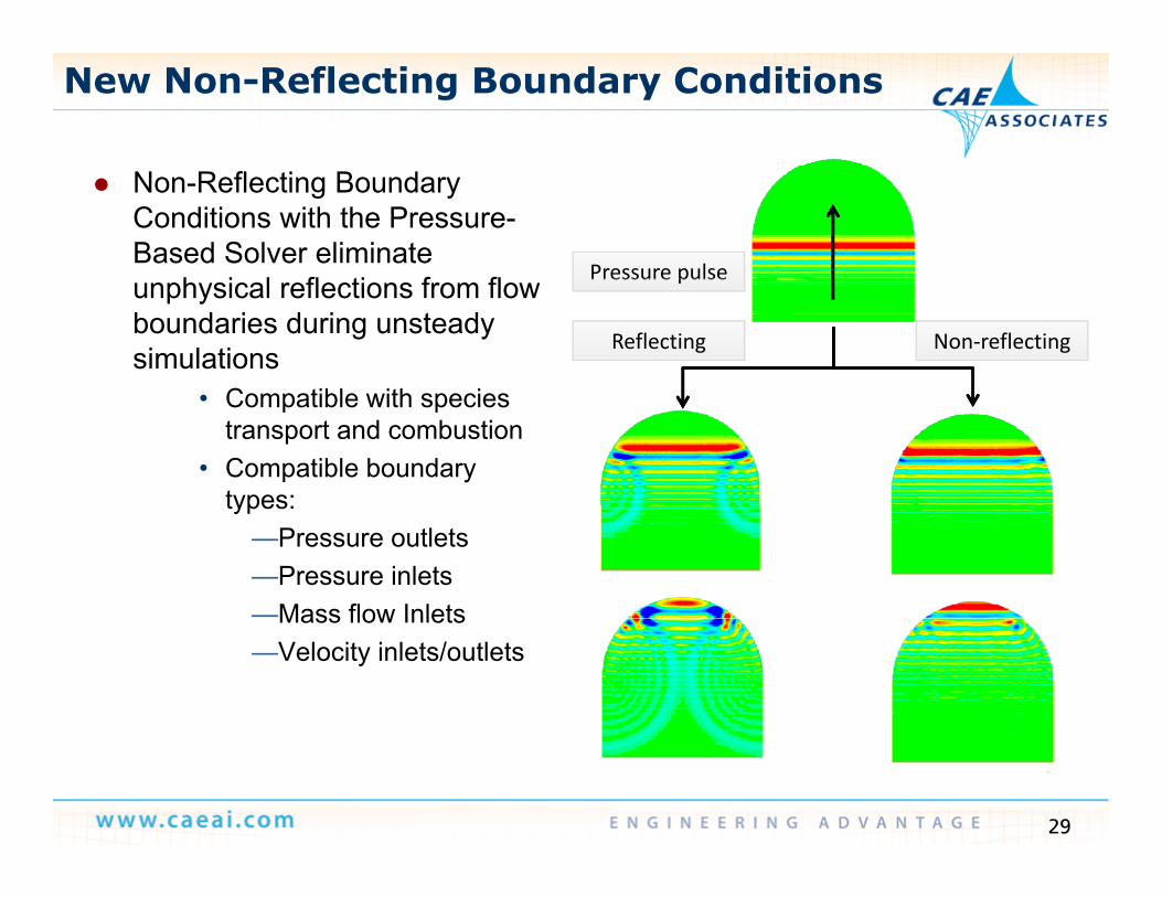
New Non-Reflecting Boundary Conditions
Non-Reflecting Boundary Conditions with the Pressure-Based Solver eliminate
h i l fl ti f fl Pressure pulseunphysical reflections from flow boundaries during unsteady simulations
C tibl ith i
Reflecting Non‐reflecting
Pressure pulse
• Compatible with species transport and combustion
• Compatible boundary types:types:
—Pressure outlets—Pressure inlets—Mass flow InletsMass flow Inlets—Velocity inlets/outlets
29
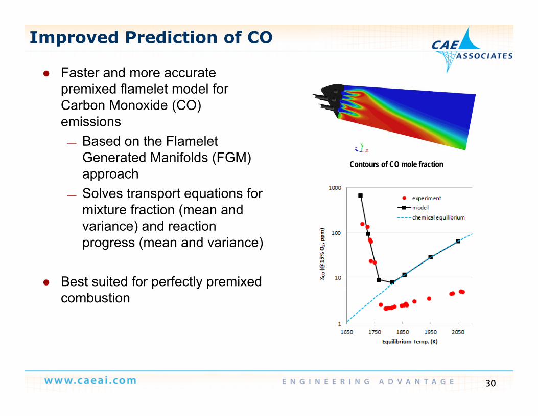
Improved Prediction of CO
Faster and more accurateFaster and more accurate premixed flamelet model for Carbon Monoxide (CO) emissions
— Based on the Flamelet Generated Manifolds (FGM) approach
Contours of CO mole fraction
— Solves transport equations for mixture fraction (mean and variance) and reaction progress (mean and variance)
Best suited for perfectly premixed p y pcombustion
30
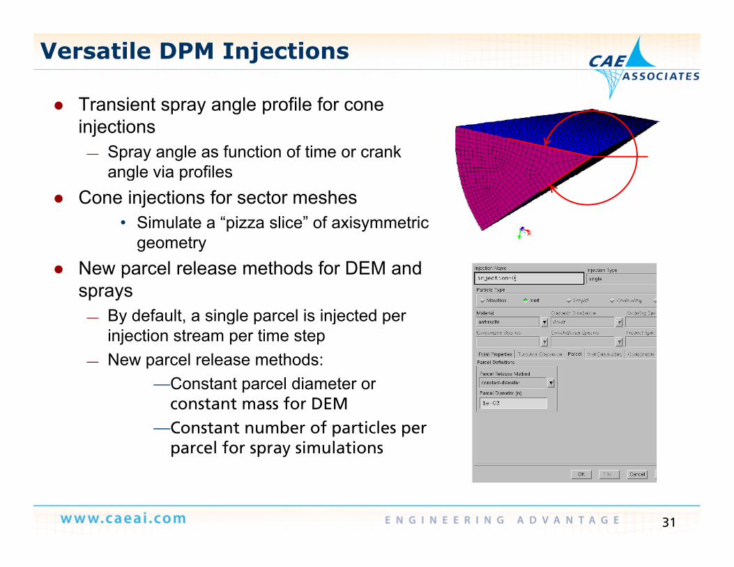
Versatile DPM Injections
Transient spray angle profile for cone Transient spray angle profile for cone injections
— Spray angle as function of time or crank angle via profilesangle via profiles
Cone injections for sector meshes• Simulate a “pizza slice” of axisymmetric
geometrygeometry New parcel release methods for DEM and
sprays— By default a single parcel is injected perBy default, a single parcel is injected per
injection stream per time step— New parcel release methods:
—Constant parcel diameter orpconstant mass for DEM
—Constant number of particles per parcel for spray simulations
31
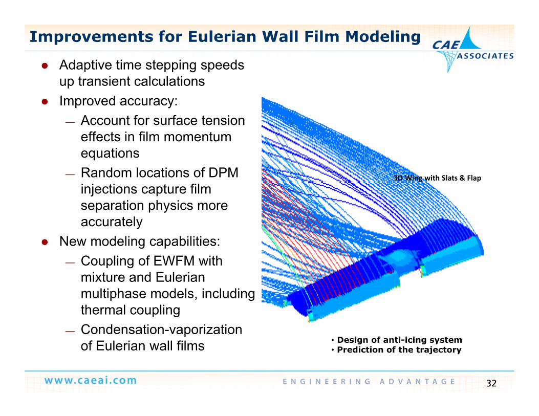
Improvements for Eulerian Wall Film Modeling
Adaptive time stepping speeds t i t l l tiup transient calculations
Improved accuracy:— Account for surface tension
effects in film momentum equations
— Random locations of DPM 3D Wing with Slats & Flap
injections capture film separation physics more accurately
g p
New modeling capabilities:— Coupling of EWFM with
mixture and Eulerian multiphase models, including thermal coupling
— Condensation-vaporization • Design of anti icing system
32
of Eulerian wall films • Design of anti-icing system• Prediction of the trajectory
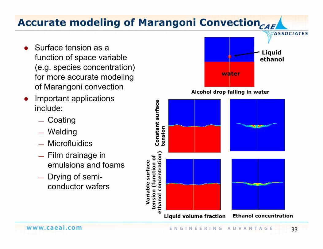
Accurate modeling of Marangoni Convection
S rface tension as a Surface tension as a function of space variable (e.g. species concentration) for more accurate modeling water
Liquid ethanol
for more accurate modeling of Marangoni convection
Important applications include: ac
e
Alcohol drop falling in water
include:— Coating— Welding
f onst
ant
surf
an
sion
— Microfluidics— Film drainage in
emulsions and foamsC
ote
n
rfac
e ti
on o
f tr
atio
n)
— Drying of semi-conductor wafers
Var
iab
le s
ur
nsi
on (
fun
ctan
ol c
once
nt
33
Vte
net
ha
Ethanol concentrationLiquid volume fraction
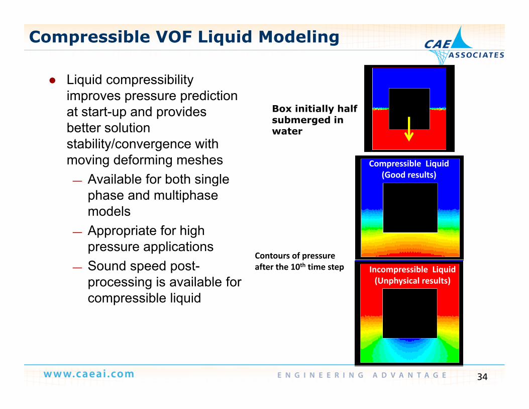
Compressible VOF Liquid Modeling
Li id ibilit Liquid compressibility improves pressure prediction at start-up and provides better solution
Box initially half submerged in
better solution stability/convergence with moving deforming meshes
Available for both single
water
Compressible Liquid(Good results)— Available for both single
phase and multiphase models Appropriate for high
( )
— Appropriate for high pressure applications
— Sound speed post-processing is available for
Contours of pressure after the 10th time step Incompressible Liquid
(Unphysical results)processing is available for compressible liquid
(Unphysical results)
34
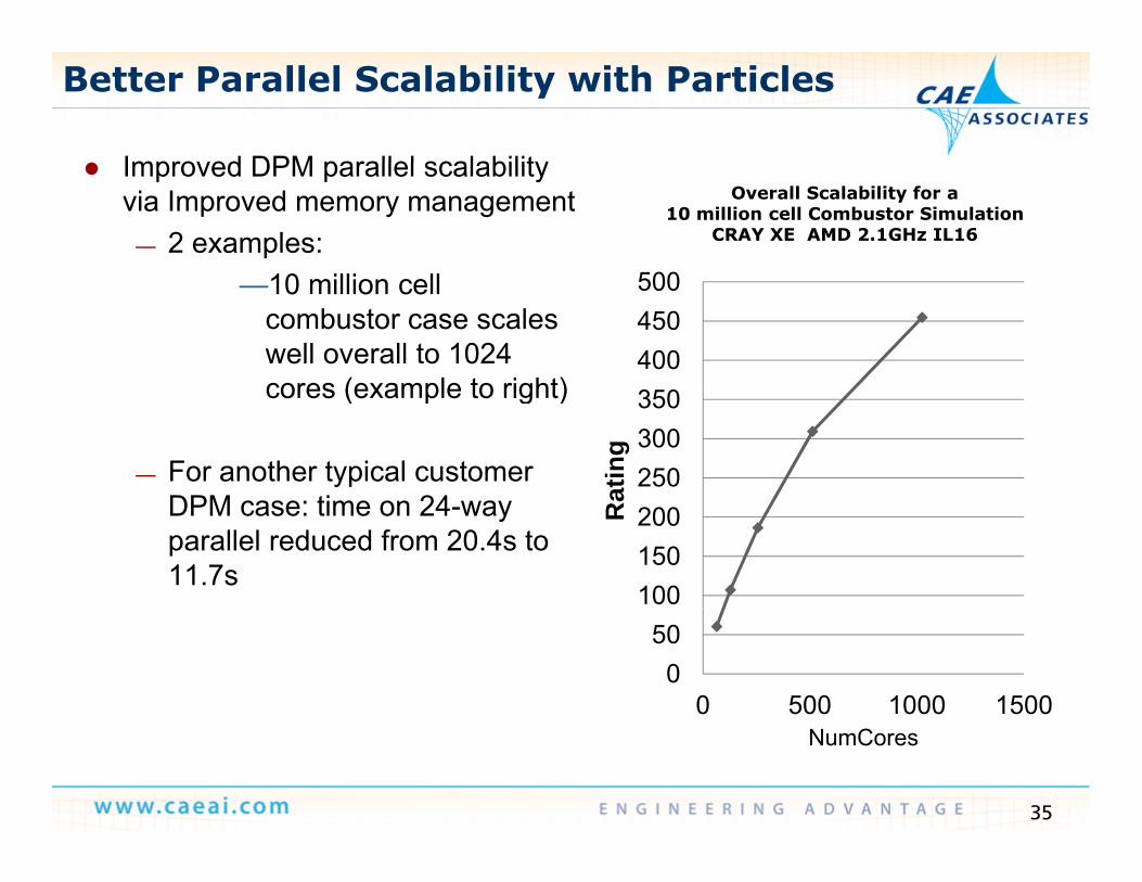
Better Parallel Scalability with Particles
Improved DPM parallel scalability Improved DPM parallel scalability via Improved memory management
— 2 examples:10 illi ll 500
Overall Scalability for a 10 million cell Combustor Simulation
CRAY XE AMD 2.1GHz IL16
—10 million cell combustor case scales well overall to 1024 cores (example to right)
400450500
cores (example to right)
— For another typical customer DPM ti 24
250300350
atin
g
DPM case: time on 24-way parallel reduced from 20.4s to 11.7s
100150200R
a
050
0 500 1000 1500
35
NumCores
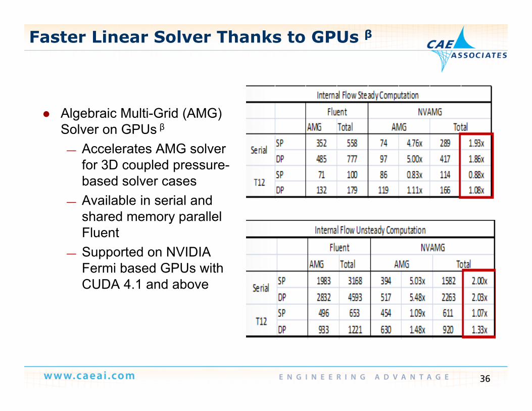
Faster Linear Solver Thanks to GPUs β
Algebraic Multi-Grid (AMG) Solver on GPUs βSolver on GPUs β
— Accelerates AMG solver for 3D coupled pressure-based solver casesbased solver cases
— Available in serial and shared memory parallel FluentFluent
— Supported on NVIDIA Fermi based GPUs with CUDA 4 1 and aboveCUDA 4.1 and above
36
Outline
Design Iteration/Optimization using CFX and DX— Demo
O FSI— One-way FSI
ANSYS Meshing v14 5 ANSYS Meshing v14.5
ANSYS CFX v14.5
ANSYS Fluent v14.5
Shape Optimization using Fluent Adjoint MethodD
37
— Demo
Adjoint Method
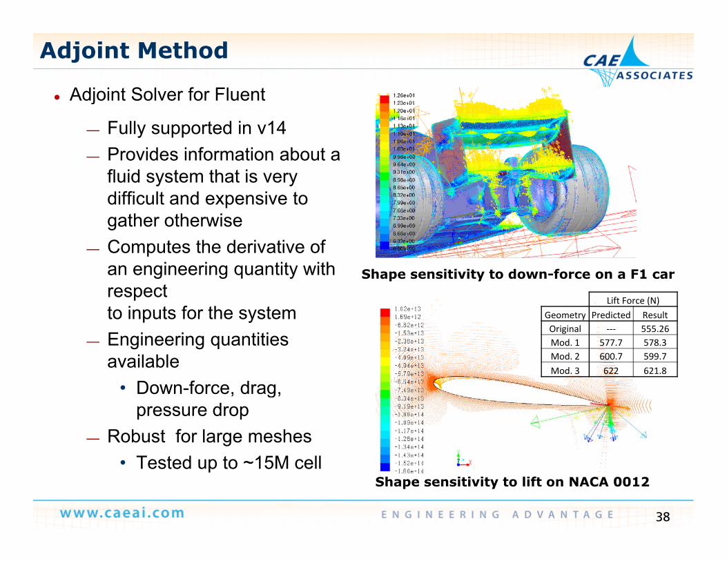
● Adjoint Solver for Fluent j
— Fully supported in v14— Provides information about a
fluid system that is veryfluid system that is very difficult and expensive to gather otherwiseComputes the derivative of— Computes the derivative of an engineering quantity with respect to inputs for the system
Shape sensitivity to down-force on a F1 car
Lift Force (N)Geometry Predicted Resultto inputs for the system
— Engineering quantities available
• Down force drag
Geometry Predicted ResultOriginal ‐‐‐ 555.26Mod. 1 577.7 578.3Mod. 2 600.7 599.7Mod. 3 622 621.8
• Down-force, drag, pressure drop
— Robust for large meshesT t d t 15M ll
38
• Tested up to ~15M cellShape sensitivity to lift on NACA 0012
More Capabilities for the Adjoint Solver
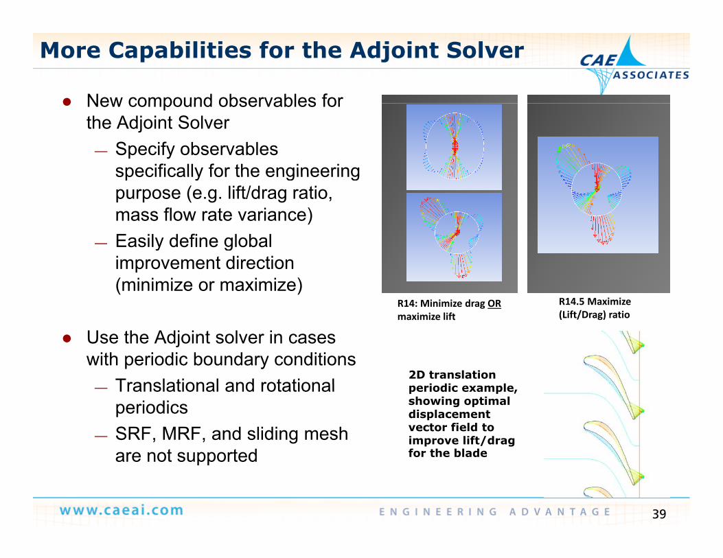
New compound observables for New compound observables for the Adjoint Solver
— Specify observables specifically for the engineeringspecifically for the engineering purpose (e.g. lift/drag ratio, mass flow rate variance)
— Easily define global— Easily define global improvement direction (minimize or maximize)
R14: Minimize drag OR i i lift
R14.5 Maximize (Lift/Drag) ratio
Use the Adjoint solver in cases with periodic boundary conditions
Translational and rotational
maximize lift (Lift/Drag) ratio
2D translation i di l — Translational and rotational
periodics— SRF, MRF, and sliding mesh
are not supported
periodic example, showing optimal displacement vector field to improve lift/drag for the blade
39
are not supported for the blade


