ERDC/CHL CHETN-IX-21 August 2009 Calculating Forces on Components of Hydraulic Structures by E. Allen Hammack, Moira T. Fong, and Richard L. Stockstill PURPOSE: This Coastal and Hydraulics Engineering Technical Note (CHETN) demonstrates a means of calculating hydraulic forces acting on submerged surfaces of hydraulic structures. The primary concern in evaluating the hydraulic performance of a structure is whether it can with- stand the imposed hydraulic forces. Forces acting on components such as stilling basins, spillway faces, bridge piers, culvert valves, spillway gates, lock guard walls, floodwalls, etc., must be accurately estimated to ensure appropriate structural, mechanical, and geotechnical design. A method of calculating the forces acting on surfaces within the domain of a computational flow model has been developed. This process of integrating the primary flow variables over surfaces of interest is described. A numerical example of an application to determine the magnitude and distribution of the hydrodynamic loads acting on a lock culvert valve is presented. BACKGROUND: Design and evaluation of hydraulic structures requires an understanding of the interaction between the flow and the components of the structure. The non-hydrostatic forces generated by the flowing water are of particular interest. Historically, physical models have been the primary means for predicting hydrodynamic forces on hydraulic structures. Laboratory stud- ies of hydraulic loadings require relatively large-scale physical models which are expensive to construct, instrument, and operate. The hydraulic evaluation costs can be decreased if computa- tional methods are used in lieu of such physical model studies. Numerical models capable of calculating hydraulic loads on bridge piers, lock guard walls, culvert valves, tainter valves, floodwalls, and moored ships will result in more cost-effective structural, mechanical, and geo- technical designs. Methods whereby numerical flow models are used to determine the hydraulic performance of components on lock gates (shown in Figure 1), dams, bulkheads, and valves are being developed by the Coastal and Hydraulics Laboratory, U.S. Army Engineer Research and Development Center. These advances will enable engineers to calculate hydraulic loads on structural and mechanical components of locks and dams. The result will be a modeling system that can esti- mate hydraulic forces on the structures and the hydraulic influence of various components of hydraulic structures. HYDRAULICS: The three-dimensional (3-D) Navier-Stokes module of the flow solver, Adap- tive Hydraulics (ADH) (http://adh.usace.army.mil/), has been applied to hydraulic structures such as locks, intakes, outlets, and weirs (Stockstill 2009; Stockstill et al. 2006; Stockstill and Berger 2000). Finite-element models of these structures employ tetrahedral elements with sizes often varying over several orders of magnitude. The flow field is modeled using the Reynolds- Averaged Navier-Stokes (RANS) equations. The 3-D RANS equations have four degrees of freedom: the pressure and the three components of fluid velocity. Solution of these primary flow
Transcript
ERDC/CHL CHETN-IX-21 August 2009
Calculating Forces on Components
of Hydraulic Structures
by E. Allen Hammack, Moira T. Fong, and Richard L. Stockstill
PURPOSE: This Coastal and Hydraulics Engineering Technical Note (CHETN) demonstrates a means of calculating hydraulic forces acting on submerged surfaces of hydraulic structures. The primary concern in evaluating the hydraulic performance of a structure is whether it can with-stand the imposed hydraulic forces. Forces acting on components such as stilling basins, spillway faces, bridge piers, culvert valves, spillway gates, lock guard walls, floodwalls, etc., must be accurately estimated to ensure appropriate structural, mechanical, and geotechnical design.
A method of calculating the forces acting on surfaces within the domain of a computational flow model has been developed. This process of integrating the primary flow variables over surfaces of interest is described. A numerical example of an application to determine the magnitude and distribution of the hydrodynamic loads acting on a lock culvert valve is presented.
BACKGROUND: Design and evaluation of hydraulic structures requires an understanding of the interaction between the flow and the components of the structure. The non-hydrostatic forces generated by the flowing water are of particular interest. Historically, physical models have been the primary means for predicting hydrodynamic forces on hydraulic structures. Laboratory stud-ies of hydraulic loadings require relatively large-scale physical models which are expensive to construct, instrument, and operate. The hydraulic evaluation costs can be decreased if computa-tional methods are used in lieu of such physical model studies. Numerical models capable of calculating hydraulic loads on bridge piers, lock guard walls, culvert valves, tainter valves, floodwalls, and moored ships will result in more cost-effective structural, mechanical, and geo-technical designs.
Methods whereby numerical flow models are used to determine the hydraulic performance of components on lock gates (shown in Figure 1), dams, bulkheads, and valves are being developed by the Coastal and Hydraulics Laboratory, U.S. Army Engineer Research and Development Center. These advances will enable engineers to calculate hydraulic loads on structural and mechanical components of locks and dams. The result will be a modeling system that can esti-mate hydraulic forces on the structures and the hydraulic influence of various components of hydraulic structures.
HYDRAULICS: The three-dimensional (3-D) Navier-Stokes module of the flow solver, Adap-tive Hydraulics (ADH) (http://adh.usace.army.mil/), has been applied to hydraulic structures such as locks, intakes, outlets, and weirs (Stockstill 2009; Stockstill et al. 2006; Stockstill and Berger 2000). Finite-element models of these structures employ tetrahedral elements with sizes often varying over several orders of magnitude. The flow field is modeled using the Reynolds-Averaged Navier-Stokes (RANS) equations. The 3-D RANS equations have four degrees of freedom: the pressure and the three components of fluid velocity. Solution of these primary flow
Report Documentation Page Form ApprovedOMB No. 0704-0188
Public reporting burden for the collection of information is estimated to average 1 hour per response, including the time for reviewing instructions, searching existing data sources, gathering andmaintaining the data needed, and completing and reviewing the collection of information. Send comments regarding this burden estimate or any other aspect of this collection of information,including suggestions for reducing this burden, to Washington Headquarters Services, Directorate for Information Operations and Reports, 1215 Jefferson Davis Highway, Suite 1204, ArlingtonVA 22202-4302. Respondents should be aware that notwithstanding any other provision of law, no person shall be subject to a penalty for failing to comply with a collection of information if itdoes not display a currently valid OMB control number.
1. REPORT DATE AUG 2009 2. REPORT TYPE
3. DATES COVERED 00-00-2009 to 00-00-2009
4. TITLE AND SUBTITLE Calculating Forces on Components of Hydraulic Structures
5a. CONTRACT NUMBER
5b. GRANT NUMBER
5c. PROGRAM ELEMENT NUMBER
6. AUTHOR(S) 5d. PROJECT NUMBER
5e. TASK NUMBER
5f. WORK UNIT NUMBER
7. PERFORMING ORGANIZATION NAME(S) AND ADDRESS(ES) U.S. Army Engineer Research and Development Center,EnvironmentalLaboratory,3909 Halls Ferry Road,Vicksburg,MS,39180-6199
8. PERFORMING ORGANIZATIONREPORT NUMBER
9. SPONSORING/MONITORING AGENCY NAME(S) AND ADDRESS(ES) 10. SPONSOR/MONITOR’S ACRONYM(S)
11. SPONSOR/MONITOR’S REPORT NUMBER(S)
12. DISTRIBUTION/AVAILABILITY STATEMENT Approved for public release; distribution unlimited
13. SUPPLEMENTARY NOTES
14. ABSTRACT
15. SUBJECT TERMS
16. SECURITY CLASSIFICATION OF: 17. LIMITATION OF ABSTRACT Same as
Report (SAR)
18. NUMBEROF PAGES
11
19a. NAME OFRESPONSIBLE PERSON
a. REPORT unclassified
b. ABSTRACT unclassified
c. THIS PAGE unclassified
Standard Form 298 (Rev. 8-98) Prescribed by ANSI Std Z39-18
ERDC/CHL CHETN-IX-21 August 2009
variables allows for the calculation of forces acting on particular surfaces within the flow domain.
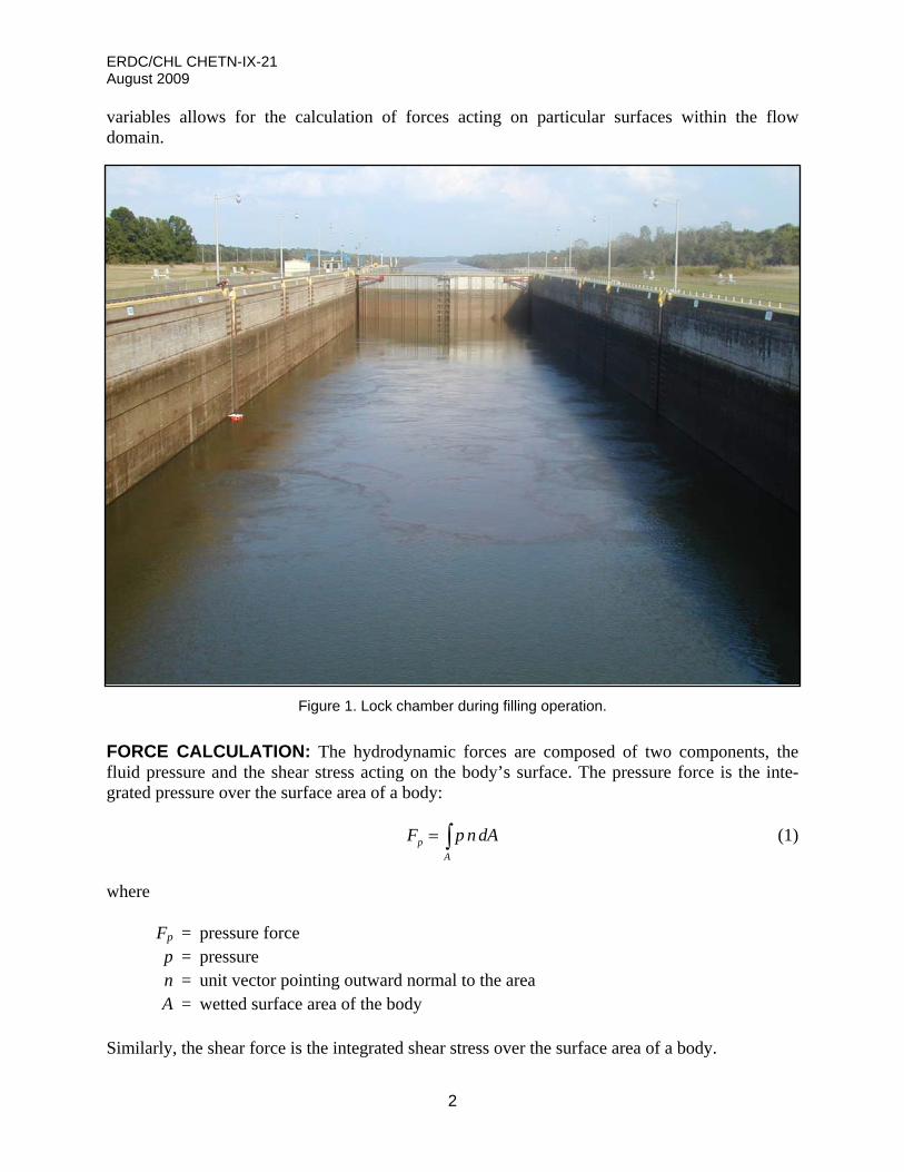
Figure 1. Lock chamber during filling operation.
FORCE CALCULATION: The hydrodynamic forces are composed of two components, the fluid pressure and the shear stress acting on the body’s surface. The pressure force is the inte-grated pressure over the surface area of a body:
(1) p
A
F p n d A
where
Fp = pressure force p = pressure n = unit vector pointing outward normal to the area A = wetted surface area of the body
Similarly, the shear force is the integrated shear stress over the surface area of a body.
2
ERDC/CHL CHETN-IX-21 August 2009
s
A
F dA (2)
where
Fs = shear force τ = shear stress
The shear stress acting on a surface is calculated as:
21
2 fC V (3)
where
Cf = friction coefficient ρ = fluid density V = velocity vector of the fluid
DISCHARGE CALCULATION: The total discharge, Q, through an area is the integral of the velocity through an area.
(4) A
Q V n d A
ADH IMPLEMENTATION: The FRC (force) card has been created for the ADH boundary condition file (project_name.bc) for the user to specify on which surfaces in the flow domain the hydraulic forces are to be calculated. Table 1 summarizes the format of the FRC card.
Table 1. FRC card description.
Field Type Value Description
1 Character FRC Card Type
2 Integer > 0 Boundary Face String
Each surface of the flow domain is defined by one or more face strings in the boundary condition file. An FRC card must be included for each face string on which the user wants hydraulic forces to be calculated. The forces’ routine performs two major calculations on a surface element: inte-gration of the pressures over the element area to determine the pressure force and integration of the velocities to determine the shear force. The units of the calculated forces are determined by the fluid density and gravity defined in the boundary condition file and the length units of the mesh.
When the FRC card is included in the boundary condition file, two additional ADH data files are created: project_name_frc.dat and project_name_frc_coord.dat. The file project_name_frc.dat
3
ERDC/CHL CHETN-IX-21 August 2009
contains information for each element in each boundary face string used in conjunction with the FRC card. Specifically, this file contains the following quantities for each element of the face string: the x-, y-, and z-coordinates of the centroid, the components of pressure, the element area, the pressure force components, the shear stress components, and the total force components. These quantities are grouped by the face string number. In addition, the sum of all the x-, y-, and z-components of the forces acting on the elements in a face string are listed. The force data are listed for each face string and for each time-step specified by the output control section of the boundary condition file. Since the output provides the location and direction of the force acting on each element face in the face string, the magnitude and direction of resultant forces and moments can be calculated from the ADH output.
VALIDATION: The hydraulic force calculation capabilities were tested on a 250-m3/sec flow of water though a duct with an abrupt contraction. The duct is 100 m long and has an abrupt vertical contraction 50 m downstream of the inlet. The 100-m-long duct is 5 m wide by 10 m tall and has an abrupt vertical contraction 50 m downstream of the inflow boundary to a width of 5 m and a height of 5 m. No friction or gravitational force acted on the flow. The pressure at the upstream end is 53,565 N/m2 (gage), and the flow issues into the atmosphere where the (gage) pressure is zero. The upstream area, A1, is 50 m2, and the downstream area, A2, is 25 m2. Figure 2 is a sche-matic of the abrupt contraction geometry.
Figure 2. Abrupt contraction geometry.
By continuity, the upstream velocity, V1, is 5 m/sec and the outflow velocity, V2, is 10 m/sec. The sum of the forces in the longitudinal direction is equal to the change in momentum.
1 1 2 2 2 1p A p A F Q V V (5)
where
4
ERDC/CHL CHETN-IX-21 August 2009
ρ = fluid density (1,000 kg/m3) Q = flow rate p = boundary pressure F = hydraulic force on the offset
The subscripts, 1 and 2, refer to upstream and downstream ends of the duct, respectively. Since the outflow pressure, p2, is zero, the force on the offset is
1 1 2 1F p A Q V V (6)
or
2 2 3 353,565 N/m 50 m 1,000 kg/m 250 m /sec 10 m/sec 5 m/secF
This simplified example finds that the longitudinal force developed on the offset is 1,428 kN.
The three total force components calculated by ADH are 1,381 kN (longitudinal, Fx), 0 kN (lateral, Fy), and 0 kN (vertical, Fz). For the longitudinal force, the ADH calculation differs from the analytical solution by 47 kN or 3.3 percent. Finer resolution near the edge of the expansion corner would decrease the size of the elements where the pressure is rapidly changing, which would reduce the difference in the analytical and ADH-calculated forces.
Validation of the discharge calculation capabilities in ADH was performed by comparing the discharge at the outflow boundary (calculated) to the discharge at the inflow (specified). By con-tinuity, these values should be equal. For the abrupt contraction, ADH calculates the flux through the outflow boundary as 249.95 m3/sec, which differs from the inflow discharge by 0.05 m3/sec or 0.02 percent.
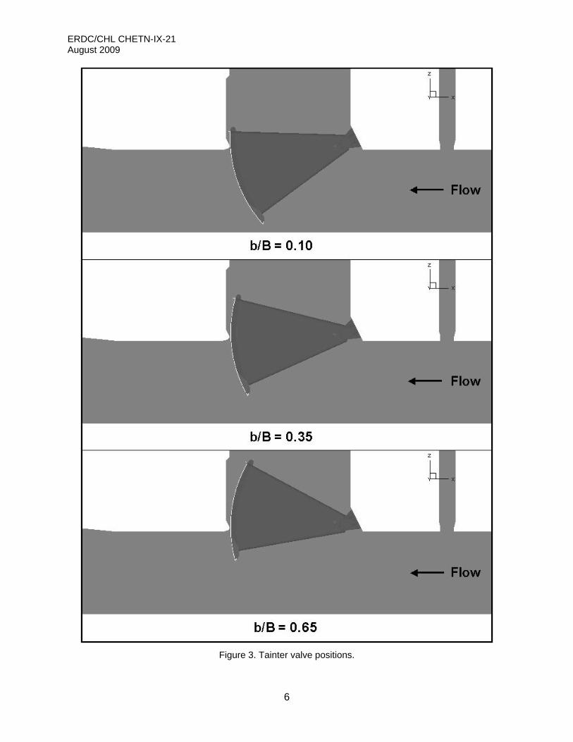
APPLICATION: The hydraulic forces acting on a lock culvert valve were calculated for three different valve positions. The pressure head was 34.4 m for all three valve positions, so, the dif-ferences in the forces acting on the valve are caused by the orientation of the valve. The three different valve positions are shown in Figure 3. The valve positions are labeled based on the normalized valve opening, the distance, b, from the bottom tip of the valve to the culvert invert divided by the culvert height, B.
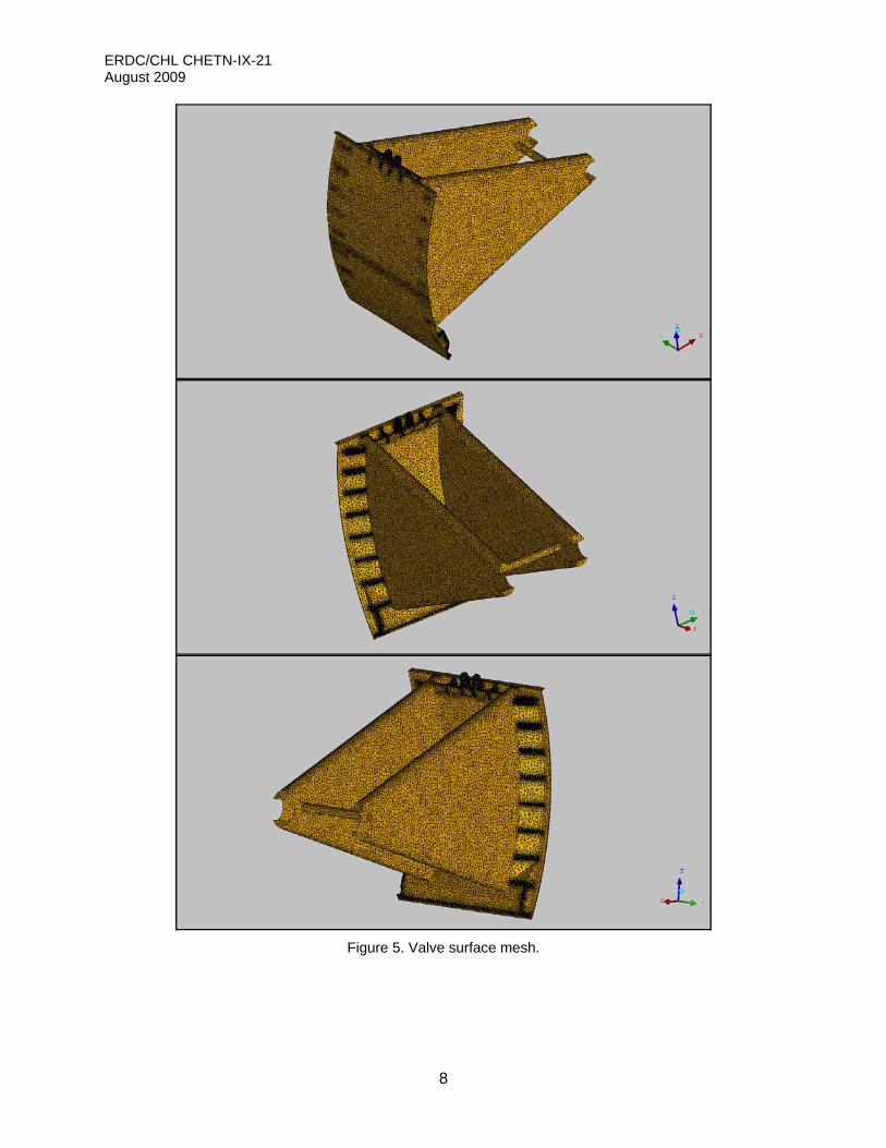
The surface geometry comprises more than 75,000 elements. Such high resolution is required to capture valve details as small as 13 mm found on the valve. Figures 4 and 5 show the valve geometry and surface meshes, respectively.
Because of its complexity, the valve surface geometry was divided into five pieces during meshing. Each piece was a face string so in order to determine the total force on the valve, the forces for each face string were calculated. The total force on the structure (in each direction) is the sum of forces of each face string. Table 2 summarizes the force results of the three valves.
5
ERDC/CHL CHETN-IX-21 August 2009
6
Figure 3. Tainter valve positions.
ERDC/CHL CHETN-IX-21 August 2009
Figure 4. Valve surface geometry.
7
ERDC/CHL CHETN-IX-21 August 2009
Figure 5. Valve surface mesh.
8
ERDC/CHL CHETN-IX-21 August 2009
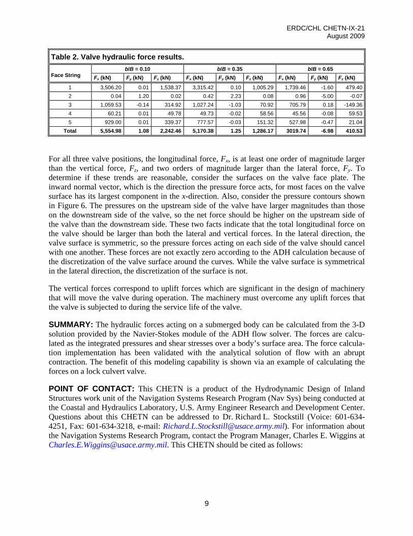
Table 2. Valve hydraulic force results.
b/B = 0.10 b/B = 0.35 b/B = 0.65 Face String Fx (kN) Fy (kN) Fz (kN) Fx (kN) Fy (kN) Fz (kN) Fx (kN) Fy (kN) Fz (kN)
Total 5,554.98 1.08 2,242.46 5,170.38 1.25 1,286.17 3019.74 -6.98 410.53
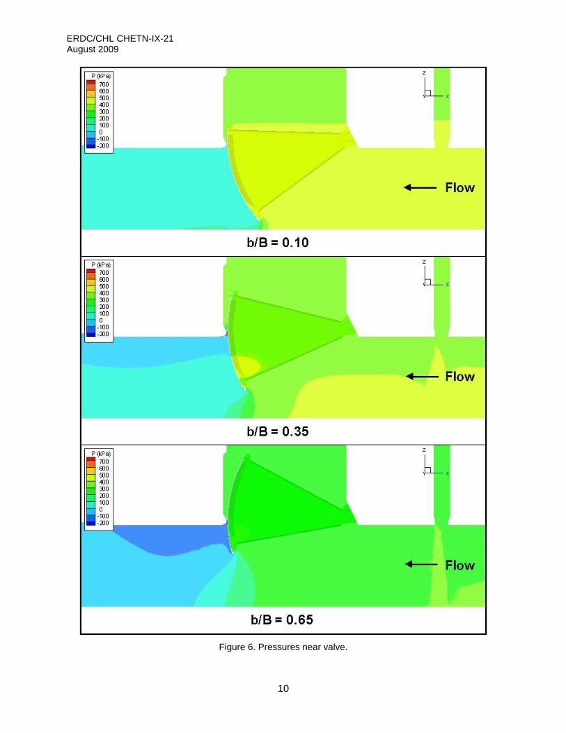
For all three valve positions, the longitudinal force, Fx, is at least one order of magnitude larger than the vertical force, Fz, and two orders of magnitude larger than the lateral force, Fy. To determine if these trends are reasonable, consider the surfaces on the valve face plate. The inward normal vector, which is the direction the pressure force acts, for most faces on the valve surface has its largest component in the x-direction. Also, consider the pressure contours shown in Figure 6. The pressures on the upstream side of the valve have larger magnitudes than those on the downstream side of the valve, so the net force should be higher on the upstream side of the valve than the downstream side. These two facts indicate that the total longitudinal force on the valve should be larger than both the lateral and vertical forces. In the lateral direction, the valve surface is symmetric, so the pressure forces acting on each side of the valve should cancel with one another. These forces are not exactly zero according to the ADH calculation because of the discretization of the valve surface around the curves. While the valve surface is symmetrical in the lateral direction, the discretization of the surface is not.
The vertical forces correspond to uplift forces which are significant in the design of machinery that will move the valve during operation. The machinery must overcome any uplift forces that the valve is subjected to during the service life of the valve.
SUMMARY: The hydraulic forces acting on a submerged body can be calculated from the 3-D solution provided by the Navier-Stokes module of the ADH flow solver. The forces are calcu-lated as the integrated pressures and shear stresses over a body’s surface area. The force calcula-tion implementation has been validated with the analytical solution of flow with an abrupt contraction. The benefit of this modeling capability is shown via an example of calculating the forces on a lock culvert valve.
POINT OF CONTACT: This CHETN is a product of the Hydrodynamic Design of Inland Structures work unit of the Navigation Systems Research Program (Nav Sys) being conducted at the Coastal and Hydraulics Laboratory, U.S. Army Engineer Research and Development Center. Questions about this CHETN can be addressed to Dr. Richard L. Stockstill (Voice: 601-634-4251, Fax: 601-634-3218, e-mail: [email protected]). For information about the Navigation Systems Research Program, contact the Program Manager, Charles E. Wiggins at [email protected]. This CHETN should be cited as follows:
9
ERDC/CHL CHETN-IX-21 August 2009
10
Figure 6. Pressures near valve.
ERDC/CHL CHETN-IX-21 August 2009
11
Hammack, E. A., M. T. Fong, and R. L. Stockstill. 2009. Calculating forces on components of hydraulic structures. Coastal and Hydraulics Engineering Techni-cal Note ERDC/CHL CHETN-IX-21. Vicksburg, MS: U.S. Army Engineer Research and Development Center, http://chl.erdc.usace.army.mil/chetn.
REFERENCES
Stockstill, R. L. 2009. Computational model of a lock filling system. Coastal and Hydraulics Engineering Technical Note ERDC/CHL CHETN-IX-18. Vicksburg, MS: U.S. Army Engineer Research and Development Center.
Stockstill, R. L., and R. C. Berger. 2000. Simulation of flow in hydraulic structures using ADH. Coastal and Hydraulics Engineering Technical Note ERDC/CHL CHETN-IX-4. Vicksburg, MS: U.S. Army Engineer Research and Development Center.
Stockstill, R. L., C. E. Kees, and R. C. Berger. 2006. Modeling free-surface flow over a weir. Coastal and Hydrau-lics Engineering Technical Note ERDC/CHL CHETN-XIII-1, Vicksburg, MS: U.S. Army Engineer Research and Development Center.
NOTE: The contents of this technical note are not to be used for advertising, publication, or promotional purposes.
Citation of trade names does not constitute an official endorsement or approval of the use of such products.