Calculation and measurement of unbalanced magnetic pull in cage induction motors with eccentric rotors. Part 1 : Analytical model A.C.Smith D.G. Dorrell Indexing terms: Cage induction motors, Rotor eccentricity, Mugnetic pull Abstract: The paper describes an analytical model for cage induction motors with a static eccentric rotor. The method is based on an airgap permeance approach including stator and rotor MMF harmonics. The stator windings are resolved into harmonic conductor density distributions that allow different seriedparallel winding connections to be accommodated in a straightforward manner. Sinusoidal and homopolar airgap field components are identified and the total airgap field distribution is used to determine the radial forces on the rotor. The model examines the principal harmonic interactions that influence the unbalanced magnetic pull. List of principal symbols b, B = airgap flux density C = constant of integration d = mean airgap diameter e = airgap electric field f= force g = average airgap length i = current j,J = surface current density k, I = harmonic wavenumber N = conductor density distribution Nb = number of rotor bars R = radius, reluctance s = slip t = time T = torque U = induced EMF v = rotor velocity 0 IEE, 1996 IEE Proceedings online no. 19960155 Paper received 23rd Junc 1995 Dr. A.C. Smith is with the Department of Enginccnng, University of Cambridge, Trumpiiigton Street, Cambridge CB2 lPZ, UK Dr. D.G. Dorrell is with the School of Electronic & Electrical Engineer- ing. The Robcrt Gordon University, Schoolhill, Aberdeen AB9 IFR, UK V = stator winding excitation voltage w = machine effective stack length X = reactance y = circumferential distance around airgap Z = impedance a = attenuation factor A = airgap permeance z = fundamental pole pitch for two-pole wave $ = airgap magnetic flux p = rotor slot harmonic number CO = supply frequency Subscripts lz = homopolar, horizontal component q = stator winding circuit R = rotor s = stator v = vertical component Superscripts h, k, 1 = harmonic wavenumbers m = airgap permeance harmonic n = stator winding harmonic * = complex conjugate 1 Introduction The manufacture of cage induction motors can produce rotor eccentricity in one of two forms: static and/or dynamic. Static eccentricity is caused by the axis of the rotor not being aligned with that of the stator although it still rotates about its own axis. This can occur for example simply due to manufacturing tolerances. Excessive static eccentricity can also occur when the bearings are incorrectly positioned or become worn. Dynamic eccentricity is caused by the centre of rota- tions of the rotor not being aligned with the rotor axis. The usual causes of dynamic eccentricity are also man- ufacturing tolerances, wear and incorrect manufacture. Rotor ‘whirl’ near a critical speed is another source of dynamic eccentricity and is an important consideration in larger, flexible-shaft machines [ 11. Obviously, static and dynamic eccentricity can exist simultaneously. In both cases significant forces can be produced that try to pull the rotor even further from the concentric posi- tion. Accurate calculation and measurement of these forces has always proved difficult owing to the inability 193 IEE Proc.-Electr. Power Appl., Vol. 143, No. 3, May 1996
Transcript
Calculation and measurement of unbalanced magnetic pull in cage induction motors with eccentric rotors. Part 1 : Analytical model
Abstract: The paper describes an analytical model for cage induction motors with a static eccentric rotor. The method is based on an airgap permeance approach including stator and rotor MMF harmonics. The stator windings are resolved into harmonic conductor density distributions that allow different seriedparallel winding connections to be accommodated in a straightforward manner. Sinusoidal and homopolar airgap field components are identified and the total airgap field distribution is used to determine the radial forces on the rotor. The model examines the principal harmonic interactions that influence the unbalanced magnetic pull.
List of principal symbols
b, B = airgap flux density C = constant of integration d = mean airgap diameter e = airgap electric field f = force g = average airgap length i = current j,J = surface current density k, I = harmonic wavenumber N = conductor density distribution Nb = number of rotor bars R = radius, reluctance s = slip t = time T = torque U = induced EMF v = rotor velocity
0 IEE, 1996 IEE Proceedings online no. 19960155 Paper received 23rd Junc 1995 Dr. A.C. Smith is with the Department of Enginccnng, University of Cambridge, Trumpiiigton Street, Cambridge CB2 lPZ, UK Dr. D.G. Dorrell is with the School of Electronic & Electrical Engineer- ing. The Robcrt Gordon University, Schoolhill, Aberdeen AB9 IFR, UK
V = stator winding excitation voltage w = machine effective stack length X = reactance y = circumferential distance around airgap Z = impedance a = attenuation factor A = airgap permeance z = fundamental pole pitch for two-pole wave $ = airgap magnetic flux p = rotor slot harmonic number CO = supply frequency Subscripts lz = homopolar, horizontal component q = stator winding circuit R = rotor s = stator v = vertical component Superscripts h, k, 1 = harmonic wavenumbers m = airgap permeance harmonic n = stator winding harmonic * = complex conjugate
1 Introduction
The manufacture of cage induction motors can produce rotor eccentricity in one of two forms: static and/or dynamic. Static eccentricity is caused by the axis of the rotor not being aligned with that of the stator although it still rotates about its own axis. This can occur for example simply due to manufacturing tolerances. Excessive static eccentricity can also occur when the bearings are incorrectly positioned or become worn. Dynamic eccentricity is caused by the centre of rota- tions of the rotor not being aligned with the rotor axis. The usual causes of dynamic eccentricity are also man- ufacturing tolerances, wear and incorrect manufacture. Rotor ‘whirl’ near a critical speed is another source of dynamic eccentricity and is an important consideration in larger, flexible-shaft machines [ 11. Obviously, static and dynamic eccentricity can exist simultaneously. In both cases significant forces can be produced that try to pull the rotor even further from the concentric posi- tion. Accurate calculation and measurement of these forces has always proved difficult owing to the inability
193 IEE Proc.-Electr. Power Appl., Vol. 143, No. 3, May 1996
of machine models to cope with the airgap variations and the limited availability of high-precision transduc- ers able to measure the radial forces between the rotor and stator. However, modern computational methods and piezoelectric transducer technology has now made the calculation and experimental investigation of UMP a realistic proposition.
The ability to determine the unbalanced magnetic pull is very relevant to the manufacture of cage machines because of the serious possibility of stator- rotor contact during operation and the influence of the pull on bearing wear. Homopolar airgap fields can also exist and find their return path through the machine covers, bearings and shaft. Their existence therefore will pose questions relating to induced EMFs and cur- rents in the motor enclosure.
Many papers have been published on the subject of UMP in rotating electrical machines. Early papers were reviewed by von Kaehne in 1962 [2] and Binns and Dye in 1972 [3]. Very early papers such as Rosenburg [4] used magnetisation curves in order to try and calculate the imbalance of flux in the airgap and hence quantify the UMP. In 1955 Summers [5] began to develop the theory of UMP by using rotating field components. Frohne [6] shows that UMP is generated by the inter- action of two fields with a pole-pair numbers differing by one. Schuisky [7] states that the fields are damped by the rotor to differing degrees depending on their pole number. Jordan [8-131 published much on the the- oretical study of UMP with several authors. These papers put forward the idea of modulation of the fun- damental MMF wave generating not only the funda- mental airgap magnetic field but also fields with higher and lower pole numbers. This is as a result of the air- gap permeance consisting o f a constant component together with a harmonic series of sinusoidal compo- nents. This directly provides the source of a problem in two-pole motors whereby a homopolar flux can be gen- erated. This flux crosses the airgap only once and returns via the shaft and casing. The phenomena was studied by Kovacs [14] and Belmans [ l , 151. Few authors try to put forward a model including the cur- rent distribution in the rotor cage and its consequential damping effect on the unbalanced magnetic pull. Fruchenicht et ul. in 1982 [l 11 attempted to model the rotor but the accuracy was not verified. Finite element analysis techniques [16, 171 can now offer solutions to this problem although this approach is still very coni- putationally expensive and often cannot provide an insight into the origins and key factors in the produc- tion of UMP.
A survey of the literature indicates that several aspects of UMP due to rotor eccentricity still remain unclear. In general terms this translates into the devel- opment of an analytical solution of a cage induction motor in which stator winding connections and the damping influence of the rotor cage can be included and the UMP quantified. The purpose of this paper is to describe an analytical approach for cage induction motors with static eccentricity and any serieslparallel stator winding connection. The winding analysis pre- sented has already proved successful in predicting the effects of general stator and rotor faults, rotor inter- rings and power-factor improvement [18-21, 24, 251. It was also used in conjunction with a conformal trans- formation of the machine to calculate UMP for a blank nonsalient rotor machine with parallel stator
194
connections [22]. The analysis is restricted to static eccentricity; this is done to maintain clarity although the analytical model can be readily extended to include dynamic eccentricity.
2 Analytical model
2. I General considerations The majority of cage motors today operate from a three-phase constant-voltage supply. The analytical model presented in this paper is generally applicable to single-phase or polyphase machines but in the interests of simplicity will be restricted to three-phase motors. This however does not preclude any series andlor par- allel winding connections in the stator. The supply volt- age is assumed to be balanced and phase winding connections can be included using a connection matrix approach outlined in [20, 231.
The rotor cage is assumed to be electrically symmet- rical. Harmonic-induced EMFs however will differ in frequency, magnitude and distribution and must be accounted for on a per-harmonic basis. The current distribution however for each harmonic is sinusoidal and the complete rotor cage can be reduced to a single rotor loop comprising two adjacent bars and the con- necting end-ring segments. This type of approach has been used previously to model rotor bar faults [19, 211.
The rotor eccentricity is assumed to be static and constant in the axial direction. It is unlikely that this situation would occur in practice for example in the event of bearing wear. However, axial variations in the eccentricity would substantially increase the complexity of the model and prove intractable. A nonuniform axial airgap is therefore ignored.
The machine is regarded as a system of coupled cir- cuits with coupling impedances used to define the inter- action between the various circuits. The following assumptions are inherent in this approach: (a) flux is assumed to cross the airgap radially (h ) saturation is ignored (c) slotting effects are ignored except in the use of Carter coefficients on the airgap length.
The influence o f rotor eccentricity on the magnetic conditions within the machine can be important in cer- tain conditions. These are normally confined to large eccentricities where localised saturation spots can occur. The effect of winding connection in this respect can also be important. Parallel winding connections can allow the individual coil currents to differ and therefore the fixed coil voltages will attempt to main- tain a relatively sinusoidal airgap field. This in turn can lead however to localised saturation of the leakage paths around the coils carrying the largest currents. Series winding connection on the other hand, ensures all coil currents rather than the coil voltages are identi- cal and hence the magnetic airgap field will become non-sinusoidal. This can lead to localised saturation of the main magnetising paths around the area corre- sponding to the shortest airgap. The cage rotor in this respect is also important because it provides many par- allel paths. Clearly saturation effects of this type are very difficult to incorporate into any analytical model and thus a numerical-based approach (e.g. a finite-ele- ment method) would be more appropriate.
2.2 Coupling impedance matrix The motor is defined analytically in terms of the cou-
I E E Proc.-Electr Powev Appl., Vol. 14.1, No. 3, M a y 1996
pling impedances between individual circuits. Each series-connected winding on the stator is regarded as a separate circuit. This allows any seriedparallel winding connections to be included. The rotor cage impedance varies with harmonic order, so coupling impedances are determined for each harmonic field. The coupling impedances are assembled into a matrix equation that relates the supply voltages to the unknown circuit cur- rents:
The submatrices E,,l remesent the stator-stator cou- L I_ .
pling impedances; [Z,Tr], stator to rotor; [ZJ, rotor to stator; [&.,I, rotor to rotor coupling impedance. [Fs] is the stator voltage to each series-connected segment of the winding and [ry], [cl represent the stator and rotor harmonic currents. The stator currents defined in eqn. 1 are those flowing through each series-connected segment of the stator winding. In general these may vary in each phase winding as well as from phase to phase. If there are series-connected segments in a phase winding and N,. rotor harmonics are considered, then the coupling impedance matrix will be square and of order (3N, + N,.).
2.3 General airgap field analysis Each stator winding circuit is resolved into a complex Fourier series of winding conductor density distribu- tions [27]. For the qth stator circuit, the stator har- monic winding distribution is given by
00
ny = 1 N $ , - i k ~ ( 2 ) n=-m
where N: is the conductor coefficient which is related to the number of effective turns in the qth stator circuit and is defined in Appendix 8.1. The machine has been linearised and y represents the circumferential co-ordi- nate. A general wavenumber k is defined using a fun- damental two-pole wave as its base. This ensures that all pole numbers are possible:
2n k = - d ( 3 )
where d is the mean airgap diameter and n represents the harmonic number. If the qth stator circuit has a current i, flowing in it,
the total stator current density distribution on the sta- tor surface is defined as follows:
i , = Re {T,eJwt} (4)
/ m
with -le --le- J , - N, I ,
The double summation in eqn. 5 represents all MMF harmonics (k) and all stator circuits (4). Assuming the flux crosses the airgap radially, Ampere’s Law can be applied to the stator surface current density to produce
b(V, t ) d Y ) = C L O j S ( V > t ) d!/ + c1 ( 7 ) J’ where b(y, t ) is the airgap flux density. go/) is the air- gap length which for static eccentricity is a function of the circumferential co-ordinate, y. C, represents a con- stant of integration which for a magnetically symmetri- cal machine would normally be zero.
IEE PvocElectr. Power Appl., Vol. 143, No. 3, M a y 1996
rotor centre Y
t - R , - - p + R z j
Fig. 1 Static eccentric Yotor
1 he airgap length for an eccentric rotor is shown in Fig. 1 and can be described simply as
where A = elg and g is the average airgap length. Inverting eqn. 8 and resolving into an airgap perme- ance Fourier series produces
g(0) = g ( l - h c o s B ) ( 8 )
00
h(y) = hme-J‘3’ (9) m=-w
with 2 m I = - d
and
L J
The airgap flux density can now be determined in gen- eral terms as
-kl 31-10 - B, = - - A ~ J ~ k
Clearly if k = -1 (i.e. n = -m), a time-varying airgap field with no circumferential variation will be pro- duced. This is a homopolar field which crosses the air- gap and returns via an axial magnetic circuit such as the motor frame, end plates, bearings and shaft. If the motor is magnetically symmetrical, m = 0 and no homopolar field can exist. The reluctance of the exter- nal magnetic circuit will clearly have a significant influ- ence on the magnitude of this flux component but it is not immediately obvious how this is incorporated into eqn. 11. However the constant of integration, C1 can be defined to include the reluctance of the external path and hence control the magnitude of homopolar fields.
The homopolar airgap flux can be obtained from the airgap field (eqn. 11) with m = -n:
2 7
4% = w J’b(Y, t ) d?4 (13) 0
195
where 2~ is the airgap circumference and w the axial motor length. Substituting for 601, t ) and rearranging gives
$h = 2 w r [E 1 Re {B;'eJwt} + C1 A' ] (14) n 4
If the external reluctance is infinite, then $,? = 0 and
The airgap flux density is thus modified to
It is evidently clear that the constant C, in eqn. 14 controls the magnitude of any homopolar fluxes. The reluctance of the magnetic circuit (ignoring the external path) must simply be the airgap reluctance R,:
The influence of the external reluctance to any homopolar fields can therefore be included by defining an attenuation factor as follows:
where R,,, is the reluctance that completes the mag- netic circuit around the airgap to the homopolar flux (e.g. frame, bearings, shaft, etc.). The airgap flux den- sity including the effect of the external magnetic circuit to any homopolar fields is thus
In practice, static eccentricity produces homopolar fields at mains frequency and the unlaminated external circuit would normally be expected to present a high reluctance path to them. It will be assumed therefore for simplicity that no homopolar fields exist.
This situation (a = 1) can be modelled by adopting the following expression for the airgap flux density:
The condition m + -n will be assumed as implicit in the following Sections. Homopolar fields can be included if necessary by reverting back to eqn. 19 for the airgap field. The airgap field produced by the stator currents can now be used to determine the various coupling impedances in Section 2.2.
2.4 Stator-stator coupling impedances The stator airgap field (eqn. 20) induces a back-EMF in each of the stator winding circuits. In the vth stator winding circuit, for example,
2 1
where e b , t ) is the electric field which can be related to the airgap flux density as follows:
This produces
( 2 3 ) where
The induced EMF is zero unless ( k , + kz + I> = 0, or
and IC2 = -(k1 + I )
Eqn. 24 represents ;he induced EMF in the'rth stator circuit by the total stator airgap field. The coupling impedance between the qth and rth stator circuits is thus defined as
and by symmetry zTq = zqy Eqn. 24 indicates the expected interaction between the airgap field and the winding harmonics of the same pole number if the rotor is concentric (m = 0). It also reveals the production of additional induced EMFs in the stator by the airgap field and winding harmonics of pole number (m + n) for an eccentric rotor.
The stator-stator coupling impedances defined in eqn. 1 by the submatrix [z,,] can now be determined from eqn. 25 by indexing through all the stator cir- cuits.
2.5 Stator-rotor coupling impedances The rotor cage can be modelled due to electrical sym- metry by a single loop. A loop is defined as any two adjacent bars connected together by the end-ring seg- ments. Each harmonic airgap field induces EMFs of differing frequencies in the rotor and coupling imped- ances must therefore be defined for each harmonic field considered.
The airgap Geld produced by the qth stator circuit is given by
(2:6) 1
} ( 2 7 )
b(y; t ) = Re B:leJ(ut+('"+z)Y) { m n
Converting to the moving rotor reference frame, y':
where v, is the rotor speed. The airgap field in rotor co- ordinates is therefore
y = v,t + y'
where
I96
sn, = 1 - (28) (rn + n)( l - s )
P IEE Proc.;Electr. Power Appl., Vol. 143, N o . 3, May 1996
and s is the fundamental rotor slip. This represents the normal definition of harmonic rotor slip.
The rotor loop conductor density can be defined in a similar fashion to that for a stator circuit (Appendix 8.21,
n - - x
The EMF induced in the reference rotor loop can now be determined following the same procedure used to define the stator- stator coupling impedances The har- monic coupling impedance between the rotor loop and the qth stator circuit is thus
For a skewed rotor cage, a conventional harmonic skew factor can be included into eqn. 30 [19]. It should be appreciated, however, that these factors are derived on the assuniption that axial variations in saturation can be ignored. It is also implicitly assumed that the skewed bar 'sees' a fixed airgap length which for an eccentric rotor will introduce an additional approxima- tion.
The rotor cage is modelled due to symmetry by a sin- gle loop. The rotor harmonic currents are therefore appropriate to that flowing in the reference loop. The remaining loop currents can easily be deduced however by an appropriate phase shift and the bar currents by subtraction of adjacent loop currents.
2.6 Rotor-rotor coupling impedances The loop current flowing in the reference rth rotor loop is of the following form:
It should be appreciated that this hdrmonic rotor cur- rent has been set up by the stator winding nnd airgap permeance This IS reflected in the harmonic number h to denote the harmonic numbers of the stator winding and airgap permeance as defined in eqn 28,
The rotor loop current density 15 therefore h = k + l
J;; Re jT7;T'i.L w t k Y ' ) 1 (31)
To obtain the total rotor current density, the individual loop components that form the complete rotor cage must be suinined together to produce
and
Subscript 1 is used here to denote the inducing har- monic numbers (h). The equation reflects the produc- tion of the normal rotor slot harmonics (differential leakage for ml = 0) and the additional harmonics (mi # 0) due to the airgap permeance harmonics. The airgap field produced by the complete rotor harmonic current distribution is therefore
n, = n1 + (~lvi, + V L ~ ) p = 0, il, A2, f3,. . . (33)
where
( 3 5 ) n
The homopolar fields produced by the rotor are again ignored. Adopting the same procedure used to calcu- late the stator- rotor impedances, the rotor-rotor cou- pling impedances are defined as follows:
2.7 Rotor-stator coupling impedances The rotor slot harmonics (n # n1 in eqn. 33) produce non-supply frequencies in the stator windings. It is common practice therefore to ignore the rotor slot har- monics in determining the rotor-stator coupling imped- ances. However, for an eccentric rotor, additional harmonic components can result in mains frequency EMFs in the stator:
It is thought that for inost practical motor designs the airgap permeance harmonics of this order are small enough to be ignored so that
n, = rl.1 and
n = nL if r t ~ ~ = pAVb
The harmonic coupling impedance between the rotor and the yth stator circuit is therefore given by
As before, a conventional harmonic skew factor can be included in eqn. 38 if rotor skew is present.
2.8 External impedances The coupling impedances defined previously do not include winding resistances or end-winding reactances. These are added to the appropriate terms externally. The rotor coupling impedanccs are determined in a per-harmonic basis and bariend-ring resistances arid reactances should be calculated at the correct frequency and added to the appropriate terms. Correction for bar skin effect can be accomplished using the multiplicative factors developed by Liwschitz -Garik [28].
2.9 Electromagnetic torque The electroniagnetic torque can be determined directly from the interaction between the rotor current density (expressed in stator co-ordinates) and the stator airgap flux density
2 7
(39) 0
where M, is the axial length and d is the mean airgap diameter. This yields
Rotor differential fields have been ignored in this expression and only the fundamental airgap permeance harmonic (m = 0) produces a steady torque. For a motor carrying balanced three-phase currents, the twice line frequency torque is zero.
197 I E E Proc -Elei.tr. l'owpr Appl., Vol 143, No. 3, M q 1996
2. IO Input power The matrix equation defined in Section 2.2 (eqn. 1) can be readily solved to produce the individual stator cir- cuit currents from the specified supply voltage. The rotor harmonic currents are also obtained and the motor torque from eqn. 40. The input power can sub- sequently be calculated in the usual fashion from the supply voltage and the known stator currents.
3 Calculation of UMP
The radial force acting on the stator or rotor can be obtained from the Maxwell stress tensor:
( 7 = - ( b i - b:) (41) 2Pfl
where the subscripts indicate normal and tangential components, respectively.
Conventionally, it is assumed that the tangential component is negligible. For a concentric motor this is considered to be a reasonable approximation, but for an eccentric rotor the assumption is less reliable. The results presented by Binns et al. [3] suggest that the tan- gential stress may be important under certain condi- tions. It is assumed here for simplicity that the assumption is reasonable provided large eccentricities are avoided.
The normal airgap flux density is determined from both the stator and rotor components:
b = b, + b, The total stress is therefore given by
and the stator radial force wave by integrating over the stator surface
27
f = W J ' O dY (43) 0
The total force or UMP can then be resolved into hor- izontal and vertical components as follows
2 7
and 27
(44)
(45)
The horizontal and vertical force (UMP) components are obtained from the preceding equations by inserting the stator and rotor airgap field components defined in eqns. 20 and 34. These airgap fields are fully defined once the winding and rotor harmonic currents have been detcrmined. The complete expressions for these force components is clearly very lengthy and for brevity the general form of each of the force components defined in eqn. 42 will be used here. The stator and rotor flux density components can be described in gen- eral terms as follows:
(46) and
(47)
where n and M? represent general harmonic numbers and p and v their corresponding wave numbers. For example, in eqn. 20,
These expressions can be transformed back into cylin- drical co-ordinates,
p = k + l
and
(49)
The horizontal and vertical UMP produced by the product of these two harmonic fields can be determined from eqns. 44 and 45 as:
Similar terms can be developed for the statoristator and rotor/rotor interactions as described in eqn. 42.
It is clear from these expressions for the UMP that in general two force components are present, a steady pull and an oscillating component at twice the line fre- quency. It is also evident that the force components are produced by the interaction of two fields whose pole number differ by one i.e. n and n + 1 or n and n ~ 1. In a concentric machine with a balanced winding, this condition cannot be met and therefore as expected there is no unbalanced magnetic pull. For a motor with an eccentric rotor however, the introduction of the air- gap permeance harmonics leads to the presence of har- monic fields whose pole numbers differ by one and hence the presence of UMP. The dominant components in this respect are generally the fundamental MMF field interacting with the low-order permeance harmon- ics. However, these will also be damped by the rotor.
The steady pull is produced by fields whose pole number differ by one and rotate around the airgap in the same direction. The oscillating component on the other hand is produced by fields whose pole number differ by one but are rotating in the opposite direction. For a series-connected three-phase stator winding with an eccentric rotor, the coil currents are constrained to be identical and hence only a forwards travelling fun- damental is produced. Any oscillating UMP is then a resultant of the interaction between the higher order harmonics. These are generally relatively small in mag- nitude and hence the oscillating component of UMP in series-connected machines is low. A fully parallel-con- nected three-phase winding however, results in an une- ven coil current distribution around the machine with an eccentric rotor. This will produce forwards and backwards rotating components of the fundamental MMF and hence their interaction with the low-order permeance harmonics can lead to much higher levels of the oscillating UMP.
The steady component of UMP acts predominantly along the axis of the narrowest airgap. However, as the load torque is increased, it has been found experimen- tally that the magnitude of the steady UMP increases with load. This is difficult to understand if one consid- ers the UMP to be derived from the fundamental air-
gap field. The fundamental resultant airgap field reduces in magnitude as the rotor speed reduces and the UMP would as a consequence also be expected to reduce. The force mechanism is clearly more involved and the permeance harmonics have to be considered. Let us assume that the main force components are pro- duced by the interaction of the low-order MMF and permeance harmonics whose magnitudes are signifi- cantly larger than the higher-order components. Con- sidering a series-connected, two-pole fundamental stator airgap field (n = 1) as follows:
-
Bk =B1 (52) The first airgap permeance harmonic (m = 1) will pro- duce an airgap field (eqn. 12) which has the same phase but is simply reduced in magnitude by the ratio (a) of the first permeance harmonic to the average air- gap length (m = 0),
-
B i = aB1 (53) Assuming that the rotor fundamental airgap field is equal in magnitude to the stator field but opposite in polarity, subject to a small phase displacement 6, then
(54) and similarly the first airgap permeance harmonic pro- duces
- -
B$ = -aBleJ6 (55) The total steady UMP produced by the stator and rotor load currents can be determined directly now from eqns. 50 and 5 1 :
(57)
It is clear from these expressions that for small load angles F there exists a small vertical component that causes the direction of the UMP to rotate slightly from the narrowest airgap (the horizontal axis). It is also clear that for small load angles the horizontal compo- nent of UMP is the dominant term as expected.
Fig. 2 Per-phure fundamental equivalent circuit
The variation of UMP with load depends on the load angle 6 and the magnitude of the stator fundamental airgap field B1. Unfortunately both of these are func- tions of the rotor speed (i.e. load) and therefore it is difficult to provide a simple explanation of the varia- tion in the UMP with load. The stator field B,’ is set up by the stator input current 6 in the conventional per-phase equivalent circuit shown in Fig. 2. The load
IEE Proc.-Electr. Power Rppl . , Vol. 143, No. 3, Muy 1996
angle 6 is represented by the phase angle between the stator input current TI and the referred rotor load cur- rent G. For most normal cage motors the load angle decreases as the rotor speed reduces from synchronous speed. This would tend to reduce the magnitude of the UMP as the load increases. However, this effect is counterbalanced by a rapidly increasing stator current 6 and hence B: . This factor on its own would increase the total UMP as the load increases. Clearly there are two contrasting influences on the magnitude of the UMP. The relative effect of each is dependent on the equivalent-circuit parameters of the particular motor. However, for most conventional c a g e motors, the increasing load current (increasing Bj ) is the dominant term and hence the resultant UMP increases as the load torque increases. This is borne out by the experi- mental measurements shown in the accompanying paper.
The variation in the steady UMP can thus be deduced in general from the interaction of the low- order MMF and airgap permeance harmonics. For a machine with parallel winding connections, the asym- metrical stator current distribution will lead to a back- wards-rotating fundamental field component. To examine the resultant UMP in this situation, the back- wards-rotating field can be significant and should be included in the simple force expressions used above. In multipole machines the UMP is produced mainly by the interaction of the fundamental MMF and the higher-order airgap permeance harmonics (m = n f 1). Clearly these permeance harmonics have a much lower magnitude and hence the influence on the UMP is less pronounced than for a two-pole motor.
* O r
0 0 01 02 0 3 0 4 eccentricity
Fig.3 -0- series connected -+- parallel connected
UMP jor series undparullel connections
4 Parallel winding connections
The analytical model has been developed in general form to accommodate any stator winding connection. It is common practice to use series, parallel or series/ parallel winding connections particularly in large three- phase motors. The winding connection plays a signifi- cant role in the magnitude of the UMP present if the rotor is eccentric.
A series-connected winding forces the individual coil currents to be constant and hence provides a sinusoidal current density distribution in the machine. An eccen- tric airgap then results in a non-sinusoidal flux density
199
distribution with the flux concentrating around the nar- rowest airgap. Significant UMP can exist in this situa- tion and it will try to reinforce the eccentricity.
A fully parallel-connected winding on the other hand, allows the coil currents to redistribute themselves and forces a constant voltage across each coil. This ensures a much more sinusoidal flux density in the air- gap and hence the levels of UMP are greatly reduced.
eccentricity Fig. 4 -M- five parallel bands, pulsating UMP (pk-pk) -e- five parallel bands, constant UMP -0- ten parallel phase bands
UMP jor series;/parallel connections
9r
01 I I I I 0 0 0 1 0 2 0 .3 0 4
Pha.se band current distributiomJor parallel connection eccentric1 t y
To illustrate the flexibility of the proposed model, the following Figures illustrate the UMP and coil current distribution in a ten-pole, double-layer motor with the stator coils connected in either series, ten parallel bands or two groups of five parallel bands in series.
Figs. 3 and 4 show the Uh4P in the series and paral- lel connections as a function of the airgap eccentricity with a blank rotor. As expected the steady UMP is sig- nificantly greater in the series-connected winding. Fig. 4 also shows the presence of a pulsating UMP in the series-parallel connection. Fig. 5 illustrates the magnitudes of the individual coil currents in the paral- lel connection. Again as expected the coil currents are different in each parallel group although the input line currents remain balanced. Fig. 6 shows the variation in the steady UMP for the series connection with load when a cage rotor is fitted. It is clear from this diagram that the magnitude of the UMP increases with load (increasing slip).
5 Conclusions
A general analytical model has been proposed that can model the influence of static eccentricity in a three- phase cage motor. It can accommodate any stator winding connection and is capable of including the effects of rotor load current. The model provides the stator coil current distribution, input power, output torque and the steady and oscillating components of UMP along the horizontal and vertical axes. The paper also examined the origins of the significant components of UMP in terms of the principal harmonic field inter- actions. An accompanying paper provides an extensive experimental verification of the method.
6 Acknowledgments
The authors wish to thank the Science and Engineering Research Council, Cambridge University and GEC Alsthom Large Machines Ltd for their financial sup- port of the project.
7
1
7
3
4
5
6
7
8
9
References
BELMANS. R., VANDENPUT, A., and GEYSEN, W.: ‘Influ- ence of unbalanced magnetic pull on the radial stability of flexi- ble-shaft induction machines’, IEE Proc. B, 1987, 134, (2), pp. 101-109 VON KAEHNE, P.: ‘Unbalanced magnetic pull in rotating elec- trical machines. Survey of published work’. E R A Report 1963, ref ZIT 142 BINNS. K.J., and DYE, M.: ‘Identification of principal factors causing unbalanced magnetic pull in cage induction motors’, Proc. IEE, 1973, 120, pp. 349-354 ROSENBERG, E.: ‘Magnetic pull in electric machines’, Tvans. Am. IEE, 1918; part 2, pp. 1425-1469 SUMMERS. E.W.: ‘Vibration in 2-pole induction motors related to slip frequency’, Trans. Am. IEE, 1955, 74, pp. 69-72 FROHNE. H.: ‘The practical importance of unbalanced magnetic pull. possibilities of calculating and damping it’, Conti Eleklro Berichte, 1967. 13, pp. 81-92; Translation: ERA Trans. 1B2617 SCHUISKY. V.W.: ‘Magnetic pull in electrical machines due to eccentricity of the rotor’, Elektvotech. Masch.bal1, 1971, 88, pp. 391-399; Translation: ERA 2958 FREISE, W., and JORDAN, H.: ‘Unbalanced magnetic pull in 3-phase a s . machines’, E T Z , 1962, A83, (9), pp. 299-303; Trans- lation: CE Trans. 7836 JORDAN, H., RODER, G., and WEIS, M.: ‘Under what cir- cumstances mav mechanical vibrations of the stator core be expected at supply frequency in four-pole three-phase asynchro- nous machines?’, Elecktvie, 1967, 21, (3 ) , pp. 91-95; Translation: ERA Trans. 1B2578
10 HAASE, H., JORDAN, H., and KOVACS, K.P.: ‘Vibratory forces as a result of shaft fluxes with two-pole induction machines’, Elektrotech (ETZ) , 1972, 93, pp. 485-486; Translation: CEGB CE 7822
200 IEE Proc.-Electr. Power Appl., Vol. 143, No. 3, May 1996
I I
12
13
14
15
16
17
18
19
20
21
22
23
24
25
26
27
FRUCHTENICHT, J., JORDAN, H., and SEINSCH, H.O.: Running instability of cage induction motors caused by harmonic
fields due to eccentricity. Part 1 : Electromagnetic spring constant and electromagnetic damping coefficient; Part 2: Self-excited transverse vibration of the rotor’, Arch. Elektroteclz., 1982, 65, pp. 27 1-292 BELMANS, R., GEYSEN, W., JORDAN, H., and VANDEN- PUT, A.: ‘Unbalanced magnetic pull and homopolar flux in three-phase induction motors with eccentric rotors’, ICEM, 1982, pp. 916-921 BELMANS, R., GEYSEN, W., JORDAN, H., and VANDEN- PUT, A.: ‘Unbalanced magnetic pull in three-phase two-pole motors with eccentric rotor’. Proceedings of international confer- ence on Ekctrical machines - design and application, 1982, Lon- don nn 65-69
1 rr- - - -~ KOVACS, K.P.: ‘Two-pole induction-motor vibrations caused by homopolar alternating fluxes’, IEEE Trans., 1977, pp. 1105-1 108 BELMANS, R., VANDENPUT, A., and GEYSEN, W.: ‘Calcu- lation of‘ the flux density and the unbalanced pull in two-pole induction machines’, Arch. Elektrotech., 1987, 70, pp. 151-1 61 SALON, S., DEBORTOLA, M., BURROW, D., and SLA- VIK, C.: ‘Calculation of circulating current between parallel windings in induction motors with eccentric rotors by the finite element method’, ICEM, 1992, pp. 371-375 DEBORTOLA, M.J., SALON, S.J., BURROW, D.W., and SLAVIK, C.J.: ‘Effect of rotor eccentricity and parallel windings on induction machine behaviour: a study using finite element analysis’, IBBE 7iuns., 1993, MAG-29, (2), pp. 1676-1682 WILLIAMSON, S.: ‘Power-factor improvement in cage-rotor induction motors’, IEE Proc. B, 1982, 130, (2) , pp. 121L129 WILLIAMSON, S., and SMITH, A.C.: ‘Steady-state analysis of 3-phase cage motors with rotor-bar and end-ring faults’, IEE Proc. B, 1982, 129, (3), pp. 93-100 WILLIAMSON, S., and MIRZOIAN, H.: ‘Analysis of cage induction motors with stator winding faults’, IEEE Trans., 1985, PAS-104, pp. 1838-1842 WILLIAMSON, S., and ABDEL-MAGIED, M.A.S.: ‘Steady- state analysis of double-cage induction motors with rotor-cage faults’, IEE Proc. B, 1987, 134, pp. 199-206 DORRELL, D.G., and SMITH, A.C.: ‘Calculation of UMP in induction motors with series or narallel windine connections’. IEEE Trans., June 1994, EC-9, (2): pp. 304-311 DORRELL, D.G.: ‘Calculation of unbalanced magnetic pull in cage induction machines’. PhD thesis, 1993, University of Cam- brcdge WILLIAMSON, S., and LAITHWAITE, E.R.: ‘Generalised har- monic analysis for the steady-state performance of sinnsoidally- excited cage induction motors’, IEE Proc. B, 1985, 132, ( 3 ) , pp. 157-163 WILLIAMSON, S., and ADAMS, N.K.: ‘Cage induction motors with inter-rings’, IEE Proc. B, 1989, 136, (6); pp. 263-274 BRADFORD, M.: ‘Unbalanced magnetic pull in a 6-pole induc- tion motor’, IEE Proc. B, 1968, 115, (11), pp. 1619-1627 WILLIAMSON, S., and SMITH, A.C.: ‘Field analysis for rotat- ing induction machines and its relationship to the equivalent-cir- cuit method’, IEE Proc. E , 1980, 127, (2), pp. 83-90
28 LIWSCHITZ-GARIK, M.M.: ‘Cornoutation of skin effect in bars of squirrel-cagc rotors’, Trans. k m . IEE, 1955, 74, pp. 768- 77 1
8 Appendix
8.1 Stator conductor density distribution If the vth stator slot contains nq,r conductors of the qth stator winding (circuit) and is positioned at y = yr, the conductor density distribution for the qth stator wind- ing is given by
00
nq = 1 N:e-J‘Y n=-ce
where k = 2n/d, the harmonic wavenumber and
T = l
Ns represents the total number of stator slots and Kfs is the nth harmonic slot breadth factor, defined as
where hs is the stator slot mouth opening.
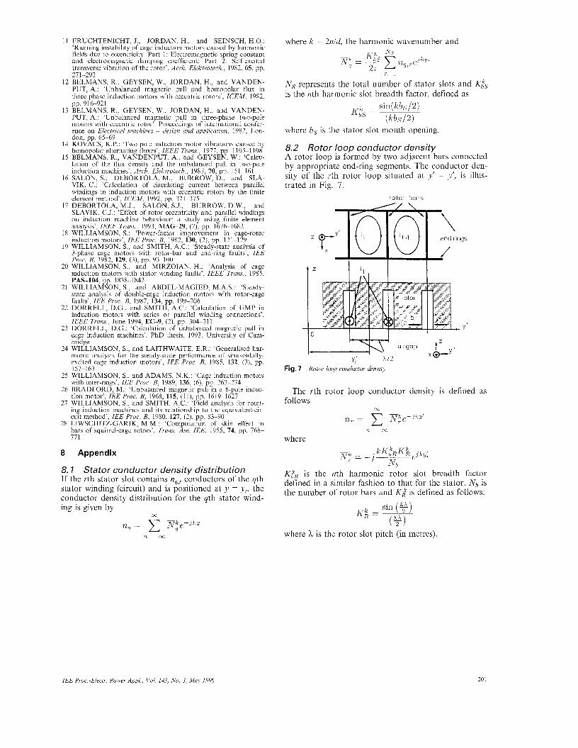
8.2 Rotor loop conductor density A rotor loop is formed by two adjacent bars connected by appropriate end-ring segments. The conductor den- sity of the rth rotor loop situated at y’ = ylr is illus- trated in Fig. 7.
rotor bars
I i , I I
Fig. 7 Rotor loop conductor density
The rth rotor loop conductor density is defined as follows
00
n, N:~-J‘Y’ n=-m
where
KtR is the nth harmonic rotor slot breadth factor defined in a similar fashion to that for the stator. Nb is the number of rotor bars and K k is defined as follows:
where h is the rotor slot pitch (in metres).
IEE Proc.-Electr. Power Appl . , Vol. 143, No. 3, May 1996 20 I