XXV Polish – Russian – Slovak Seminar “Theoretical Foundation of Civil Engineering”
Calculation of reinforced concrete structures with a set seismic stability level on an earthquake
O.V. Mkrtycheva, M.S. Busalovab * aMoscow State University of Civil Engineering (National Research University), Yaroslavskoe Shosse, 26, Moscow, 129337, Russia
bRUDN University , Miklukho-Maklaya str., 6, Moscow, 117198, Russia
Keywords: seismic resistance level; criterion of non-collapse; models of materials; concrete and reinforcement binding; nonlinear methods; seismic action
1. Summary
At the heart of the national approach to building and structure calculations on a seismic action, a regulatory document SP 14.13330.2014 "SNiP II-7-81 * "Construction in seismic region" [1] stays and it implements the
476 O.V. Mkrtychev and M.S. Busalova / Procedia Engineering 153 ( 2016 ) 475 – 482
response spectrum method of an earthquake calculation. These norms don't allow design buildings and constructions with a set seismic stability level by non-collapse criterion. Using in calculations a direct dynamic method of integrating motion equations allows you to get more appropriate results, taking into account the non-linear nature of a structure deformation in comparison with a the response spectrum method [2].
Nomenclature
u required vector of nodal displacements u v vector of nodal velocities u a vector of nodal accelerations M matrix of mass C matrix of damping K matrix of rigidity
af vector of applied loads integration parameter
For the specified level of seismic resistance following items are required. 1. To use appropriate computational methods and models (nonlinear dynamic calculation methods, seismic action
probability models, model of a nonlinear deformation of materials, volumetric finite elements with concrete and reinforcement binding take into account properly the structure and base interaction [3,4], to apply seismic systems, etc.).
2. To apply methods of probability theory and building structures reliability theory. 3. To carry out relevant research work, including those on the verification of design models, and development of
practical application techniques. 4. To develop a system of new generation of regulatory documents in the area of earthquake engineering. Following these recommendations allows more adequately perform calculations to determine the level of seismic
resistance of buildings and structures, designed for seismic areas. Some of the proposed clauses are in more detail considered below.
According to the response spectrum method, possible occurrence of nonlinearities in design operating is taken into account by only one coefficient according to table 4 in [1], that is actually in calculations linear schemes are considered only. Thus, the linear-spectral approach to intensive seismic actions calculation does not allow adequately takes into account the design behavior beyond the elastic limit. Another major issue is the need to take into account construction – soil base collaborative work. In Construction Regulations SP 14.13330.2014 "SNiP II-7-81*”Construction in seismic areas” this interaction is indirectly taken into account in determining the dynamic coefficient [1].
In real conditions in an intensive earthquake soil behaves nonlinearly, changes its properties, and there is a probability of such dangerous effects as the soil liquefaction and loss of strength [5, 6, 7] Such soil behavior has a direct impact on the reaction of the located above structure. These factors neglecting can lead to significant errors in the calculation results.
When calculating buildings and structures in view of the non-linear nature of the deformation one may apply a direct dynamic method, which is based on the direct integration of the equation of motion (1) using the implicit (2) or explicit (3) integration schemes.
aMu Cu Ku f (1)
212t t t t t t tt tu u u u u (2)
477 O.V. Mkrtychev and M.S. Busalova / Procedia Engineering 153 ( 2016 ) 475 – 482
/ 2 2t t t
t t t t t
t tu u v (3)
With this method, all calculations are performed in the time domain, it becomes possible to consider non-linearity of various types, and the use of explicit methods reduces the time of calculation.
2. Development of calculation methods
To account physical nonlinearity you can use concrete deformation diagrams, which are given in [8] (Figure 1).
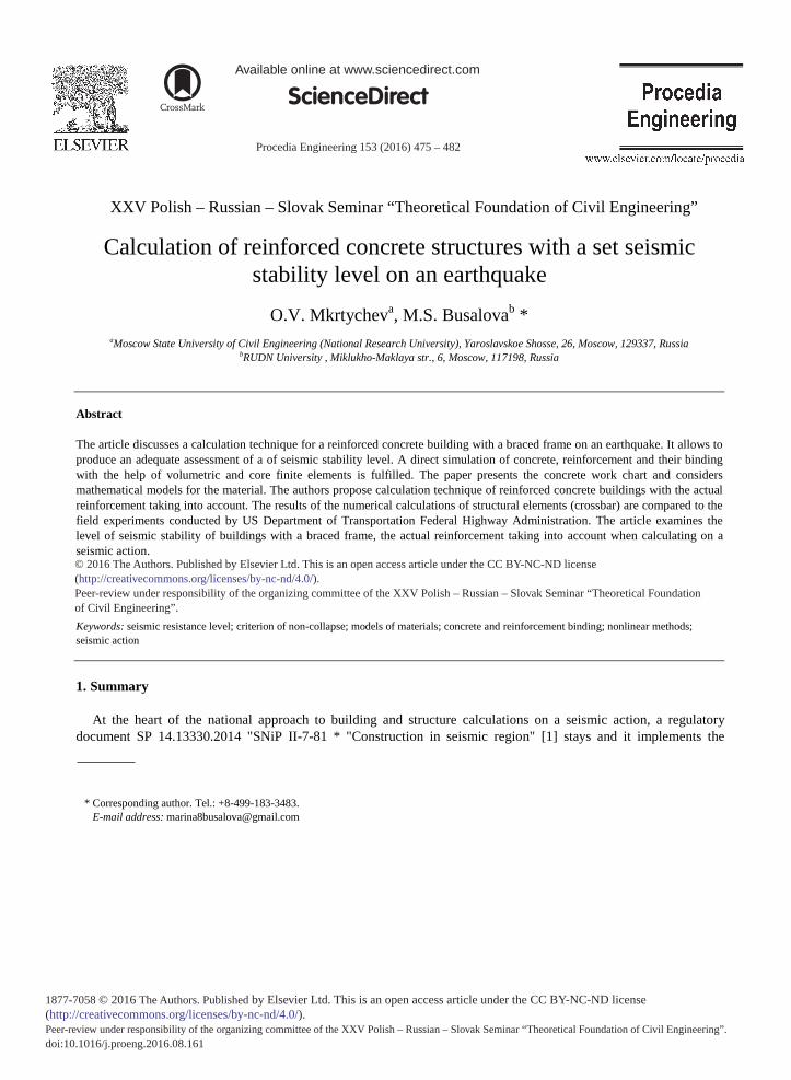
The authors have conducted their research on concrete mathematical model verification (Figures 2, 3), developed by U.S. Department of Transportation. Federal Highway Administration [9, 10, 11], with the experiment results. This mathematical model of concrete was implemented in the LS-DYNA software package.
Fig. 2. Mathematical model of concrete (CSCM – Continuous Surface Cap Model).
a) b)
478 O.V. Mkrtychev and M.S. Busalova / Procedia Engineering 153 ( 2016 ) 475 – 482
c)
Fig. 3. Mathematical model of concrete (CSCM - Continuous Surface Cap Model) a) and b) results of experiments; c) numerical studies.
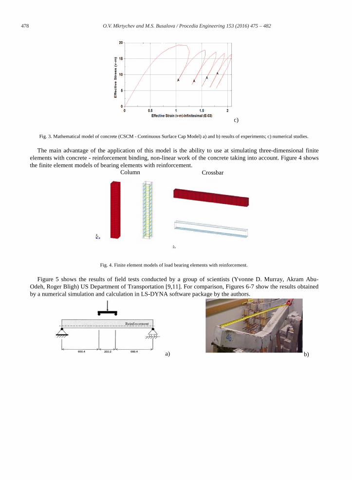
The main advantage of the application of this model is the ability to use at simulating three-dimensional finite elements with concrete - reinforcement binding, non-linear work of the concrete taking into account. Figure 4 shows the finite element models of bearing elements with reinforcement.
Column Crossbar
Fig. 4. Finite element models of load bearing elements with reinforcement.
Figure 5 shows the results of field tests conducted by a group of scientists (Yvonne D. Murray, Akram Abu-Odeh, Roger Bligh) US Department of Transportation [9,11]. For comparison, Figures 6-7 show the results obtained by a numerical simulation and calculation in LS-DYNA software package by the authors.
a) b)
479 O.V. Mkrtychev and M.S. Busalova / Procedia Engineering 153 ( 2016 ) 475 – 482
c) d)
Fig. 5. a) Estimated beam scheme; b) -c) results of the experiment, d) results of numerical simulating.
The results obtained during the experiments agree well with the results, received by the authors in LS-DYNA software package.
Thus, the possibility of simulating of load bearing construction elements with actual reinforcement taking into account allows accurately display the behavior of the structure as a whole during the seismic action [12, 13, 14].
3. Problem Statement
As an example of the developed technique we perform the calculation of a multistory reinforced concrete building with a braced frame on a seismic action. We used three-dimensional elements to simulate concrete, stem - to valve, with the corresponding algorithm of reinforcement - concrete binding being used.
The calculation scheme of a braced frame building is shown in figure 8a, figure 8b shows the reinforcement frames. The calculation was carried out on a 3-component seismic impact rated to 9 points.
Stresses Plastic deformations
Fig. 6. The results obtained by the authors in LS-DYNA software package.
480 O.V. Mkrtychev and M.S. Busalova / Procedia Engineering 153 ( 2016 ) 475 – 482
a) b)
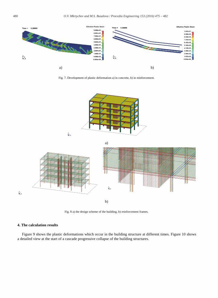
Fig. 7. Development of plastic deformation a) in concrete, b) in reinforcement.
a)
b)
Fig. 8 a) the design scheme of the building, b) reinforcement frames.
4. The calculation results
Figure 9 shows the plastic deformations which occur in the building structure at different times. Figure 10 shows a detailed view at the start of a cascade progressive collapse of the building structures.
481 O.V. Mkrtychev and M.S. Busalova / Procedia Engineering 153 ( 2016 ) 475 – 482
5. Conclusion
For a given level of seismic stability on the criterion of non - collapse in designing buildings in seismic areas, nonlinear dynamic methods, appropriate material models for simulating reinforcement and concrete with regard to their joint work and the non-linear nature of the deformation should be used. This approach allows us to estimate and analyze the actual response of the construction to a seismic action.
Fig. 9. The development of plastic deformations in the structure.
Fig. 10. Progressive collapse of the building.
482 O.V. Mkrtychev and M.S. Busalova / Procedia Engineering 153 ( 2016 ) 475 – 482
Acknowledgements
This study was performed with the support of RF Ministry of Education and Science, grant No. 7.2122.2014/K. All tests were carried out using research equipment of Head Regional Collective Research Centre of Moscow State University of Civil Engineering.
References
[1] SP 14.13330.2014 "SNIP II-7-81 *"Construction in seismic areas". Analyst, 2014, 126 p. [2] A.A. Yudakov, V.G. Boikov Numerical methods for integrating the motion equations of mechanical multicomponent systems based on the
method of direct integration of dynamics equations of a finite element method. Bulletin of Udmurt University, 2013, 1, pp 131-144. [3] Z.G. Ter-Martirosyan, A.Z. Ter-Martirosyan The rheological properties of the soil shear. Grounds, foundations and soil mechanics, 2012, 6,
pp.9-13. [4] Z.G. Ter-Martirosyan, M.N. Jaro The interaction of finite rigidity structures with two-layer foundation under seismic loads. Proceedings of
Moscow State University of Civil Engineering, 2012, 4, pp 121-125. [5] A.G. Shashkin A visco-elastic-plastic behavior model of clay soils. Urban development and geotechnical construction, 2011, 2, pp. 1-32. [6] V.N. Kukudzhanov Numerical continuum mechanics. De Gruyter Studies in Mathematical Physics 15, Berlin: De Gruyter, 2013. [7] T. Belytschko et al. Nonlinear Finite Elements for Continua and Structures, 2 edition, Wiley, 2014. [8] SP 63.13330.2012 "SNIP 52-01-2003" Concrete and reinforced concrete structures. Summary ". Analyst, 2012, 156 p. [9] US Department of Transportation. Federal Highway Administration. Evaluation of LS-DYNA Concrete. Material Model 159. Publication
NO. FHWA-HRT-05-063, May 2007, 190 p. [10] E. Buth NCHRP 350 Pendulum Test and Transition Connection Project, Letter Report for Project 408930, Texas Transportation Institute,
College Station, TX, August 2002. [11] Y.D. Murray "Users Manual for LS-DYNA Concrete Material Model 159" Report No. FHWA-HRT-05-062, Federal Highway
Administration, 2007. [12] O.V. Mkrtychev, G.A. Dzhinchvelashvili The analysis stability of the building in emergency impacts. Science and Transport Equipment,
2002, 2, pp.34-40. [13] O.V. Mkrtychev Reliability of multi-core systems in engineering structures. Thesis Abstract for the degree of Doctor of Technical Sciences,
Moscow, 2000. [14] O.V. Mkrtychev, G.A. Dzinchvelashvili, M.S. Busalova Calculation accelerogram parameters for a "Construction-Basis" model, nonlinear
properties of the soil taken into account. Procedia Engineering, 2014, Vol.91, pp. 54-57.