198
Calculations for Electrical Installations - 2

Calculations for Electrical Installations - 2


Contents
Preface vii
Use of calculators 1
Simple transposition of formulae 3
SI units 5
Conductor colour identification 7
Alternating current circuit calculations 8
Impedance 8
Inductive reactance 11
Capacitive reactance 14
Impedance in series circuits 17
Impedance triangles and power triangles 27
a.c. waveform and phasor representation 39
Alternating e.m.f. and current 39
Phasors 45
Parallel circuits involving resistance,
inductance and capacitance
54
Power factor improvement 62
Calculation without p.f. correction 64
Calculation with p.f. correction 65
Three-phase circuit calculations 69
Star-connected motors 69
Delta-connected motors (mesh) 71
Resistance and inductance in three-phase circuits 73
Three-phase circuits 78
Three-phase power 81
Voltage drop in three-phase circuits 86
v

Voltmeters and ammeters: changing the use and
extending the range
104
Voltmeters 104
Ammeters 106
Alternating current motors 110
Application of diversity factors 117
Cable selection 124
Earthing conductor calculation 124
Voltage drop and cable selection calculations 129
Earth leakage protection calculations 143
Lighting calculations 149
Units and quantities 149
Inverse square law 150
Cosine law 151
Mechanics 156
Moment of force 156
Torque 156
Power 157
Surface speed, pulley diameter and speed ratios 159
Miscellaneous examples 165
d.c. generators 165
d.c. motors 166
Alternators and synchronous motors 167
Induction motors 168
Insulation resistance 168
Formulae 173
Glossary 178
Answers 182
vi

Preface
Mathematics forms the essential foundation of electrical
installation work. Without applying mathematical functions
we would be unable to work out the size of a room which needs
lighting or heating, the size and/or the number of the lights or
heaters themselves, the number and/or the strength of the fixings
required, or the size of the cables supplying them. We would be
unable to accurately establish the rating of the fuse or circuit
breaker needed to protect the circuits, or predict the necessary
test results when testing the installation. Like it or not you will
need to be able to carry out mathematics if you want to be an
efficient and skilled electrician.
This book will show you how to perform the maths you will
need to be a proficient electrician. It concentrates on the
electronic calculator methods you would use in class and in the
workplace. The book does not require you to have a deep
understanding of how the mathematical calculations are
performed; you are taken through each topic step by step, then
you are given the opportunity yourself to carry out exercises at the
end of each chapter. Throughout the book useful references are
made to Amendment 2:2004 BS 7671 Requirements for Electrical
Regulations and the IEE On-Site Guide.
Volume 2 Electrical Installation Calculations originally written by
A. J. Watkins and R. K. Parton has been the preferred book for
many students looking to improve their mathematical
understanding of the subject for many years. This edition has
been newly updated not only to include modern methods,
but also to cover all aspects of the new City and Guilds 2330
Certificate in Electrotechnical Technology.
This second volume includes advanced calculations, in
particular those involving cable selection. As well as being
vii

invaluable to students studying for the City and Guilds 2330, it will
also be of considerable use to those involved in electrical
installation work, particularly if studying for the City and
Guilds 2391 Inspection and Testing, 2400 Design and
Verification and the 2381 exams.
viii

Use of calculators
Throughout Books 1 and 2, the use of a calculator is encouraged.
Your calculator is a tool, and like any tool practice is required to
perfect its use. A scientific calculator will be required, and
although they differ in the way the functions are carried out,
the end result is the same.
The examples are given using a Casio fx-83MS. The figures
printed on the button is the function performed when the button
is pressed. To use the function in small letters above any button
the shift button must be used.
P R A C T I C E I S I M P O R T A N T
Syntax error Appears when the figures are entered in the wrong
order.
x2 Multiplies a number by itself, i.e. 6 × 6 = 36. On
the calculator this would be 6x2 = 36. When a
number is multiplied by itself it is said to be squared.
x3 Multiplies a number by itself and then the total
by itself again, i.e. when we enter 4 on calculator
x3 = 64. When a number is multiplied in this way
it is said to be cubed.√ Gives the number which achieves the total by being
multiplied by itself, i.e.√
36 = 6. This is said to be
the square root of a number and is the opposite of
squared.
3√ Gives you the number which when multiplied by
itself three times will be the total. 3√
64 = 4 this is
said to be the cube root.
1

x−1 Divides 1 by a number, i.e. 14 = 0.25 This is the
reciprocal button and is useful in this book for finding
the resistance of resistors in parallel and capacitors in
series.
EXP The powers of 10 function, i.e.
25 × 1000 = 25 EXP × 103 = 25 000
Enter into calculator 25 EXP 3 = 25000. (Do not
enter the × or the number 10.)
If a calculation shows 10−3, i.e. 25 × 10−3 enter
25 EXP −3 = (0.025) (when using EXP if a minus
is required use the button (−))
Brackets These should be used to carry out a calculation within
a calculation. Example calculation:
32
(0.8 × 0.65 × 0.94)= 65.46
Enter into calculator 32 ÷ (0.8 × 0.65 × 0.94) =
Remember, Practice makes perfect!
2

Simple transposition offormulae
To find an unknown value:
n The subject must be on the top line and must be on its own.
n The answer will always be on the top line.
n To get the subject on its own, values must be moved.
n Any value that moves across the = sign must move
from above the line to below line or
from below the line to above the line.
EXAMPLE 1
3 × 4 = 2 × 6
3 × 4 = 2 × ?
Transpose to find ?
3 × 4
2= 6
EXAMPLE 2
2 × 6
?= 4
Step 12 × 6 = 4 × ?
Step 22 × 6
4= ?
Answer2 × 6
4= 3
3

EXAMPLE 3
5 × 8 × 6 = 3 × 20 × ?
Step 1: move 3 × 20 away from the unknown value, as the known
values move across the = sign they must move to the bottom of
the equation
5 × 8 × 4
3 × 20= ?
Step 2: Carry out the calculation
5 × 8 × 6
3 × 20= 240
60= 4
Therefore
5 × 8 × 6 = 240
3 × 20 × 4 = 240
or
5 × 8 × 6 = 3 × 20 × 4.
4

SI units
In Europe and the UK, the units for measuring different
properties are known as SI units.
SI stands for Systeme Internationale.
All units are derived from seven base units.
Base quantity Base unit Symbol
Time Second s
Electrical current Ampere A
Length Metre m
Mass Kilogram kg
Temperature Kelvin K
Luminous intensity Candela cd
Amount of substance Mole mol
S I - D E R I V E D U N I T S
Derived quantity Name Symbol
Frequency Hertz Hz
Force Newton N
Energy, work, quantity
of heat
Joule J
Electric charge, quantity
of electricity
Coulomb C
Power Watt W
Potential difference,
electromotive force
Volt V or U
Capacitance Farad F
Electrical resistance Ohm Ä
Magnetic flux Weber Wb
Magnetic flux density Tesla T
(Continued)
5

Derived quantity Name Symbol
Inductance Henry H
Luminous flux Lumen cd
Area Square metre m2
Volume Cubic metre m3
Velocity, speed Metre per second m/s
Mass density Kilogram per cubic metre kg/m3
Luminance Candela per square metre cd/m2
S I U N I T P R E F I X E S
Name Multiplier Prefix Power of 10
Tera 1000000000000 T 1 × 10¹²
Giga 1000000000 G 1 × 10⁹
Mega 1000000 M 1 × 10⁶
Kilo 1000 k 1 × 10³
Unit 1
Milli 0.001 m 1 × 10⁻³
Micro 0.000001 m 1 × 10⁻⁶
Nano 0.000000001 h 1 × 10⁻⁹
Pico 0.000000000001 r 1 × 10⁻¹²
EXAMPLE
mA Milliamp = one thousandth of an ampere
km Kilometre = one thousand metres
mv Microvolt = one millionth of a volt
GW Gigawatt = one thousand million watts
kW Kilowatt = one thousand watts
Calculator example
1 kilometre is 1 metre × 103
Enter into calculator 1 EXP 3 = (1000) metres
1000 metres is 1 kilometre × 10−3
Enter into calculator 1000 EXP −3 = (1) kilometre
1 microvolt is 1 volt × 10−6
Enter into calculator 1 EXP −6 = (1−06 or 0.000001) volts
(note sixth decimal place).
6

Conductor colouridentification
Old colour New colour Marking
Phase 1 of a.c. Red Brown L1
Phase 2 of a.c. Yellow Black L2
Phase 3 of a.c. Blue Grey L3
Neutral of a.c. Black Blue N
Note: great care must be taken when working on installations
containing old and new colours.
7

Alternating current circuitcalculations
I M P E D A N C E
In d.c. circuits, the current is limited by resistance. In a.c. circuits,
the current is limited by impedance (Z). Resistance and impedance
are measured in ohms.
For this calculation, Ohm’s law is used and Z is substituted for R.
U
Z= I or voltage (U ) ÷ impedance (ohms)
= current (amperes)
Z
Volt drop
V
I
Fig. 1
EXAMPLE 1 The voltage applied to a circuit with an impedance
of 6Ä is 200 volts. Calculate the current in the circuit.
U
Z= I
200
6= 33.33 A
8

EXAMPLE 2 The current in a 230V single phase motor is 7.6A.
Calculate the impedance of the circuit.
U
I= Z
230
7.6= 30.26 Ä
EXAMPLE 3 A discharge lamp has an impedance of 265Ä and
the current drawn by the lamp is 0.4A. Calculate the voltage.
Z × I = U
265 × 0.4 = 110 volts
EXAMPLE 4 The current through an impedance of 32Ä is 8A.
Calculate the voltage drop across the impedance.
U = I × Z
= 8 × 32
= 256 V
EXAMPLE 5 The current through an electric motor is 6.8A at
230V. Calculate the impedance of the motor.
U = I × Z
(Transpose for Z) Z = U
I
= 230
6.8
= 33.82 Ä
EXAMPLE 6 An a.c. coil has an impedance of 430Ä. Calculate
the voltage if the coil draws a current of 0.93A.
U = I × Z
(Transpose for U ) U = I × Z
= 0.93 × 430
= 400 V
9

EXERCISE 1
1. Complete the following table:
Volts (a.c.) 230 400 100 25 230
Current (A) 0.1 15 0.5 0.01 180 25
Impedance (Ä) 100 15 1000 0.05 25
2. Complete the following table:
Current (A) 1.92 3.84 18.2 7.35 4.08 8.97
Volts (a.c.) 7.5 230 107 400 235
Impedance (Ä) 2.45 12.4 96.3 56 96
3. Complete the following table:
Impedance (Ä) 232 850 0.125 1050 129
Volts (a.c.) 230 400 26.5 0.194 238 245
Current (A) 0.76 0.575 0.0065 0.436 0.056
4. A mercury vapour lamp takes 2.34A when the mains
voltage is 237V. Calculate the impedance of the lamp
circuit.
5. An inductor has an impedance of 365Ä. How much
current will flow when it is connected to a 400V a.c. supply?
6. A coil of wire passes a current of 55A when connected to a
120V d.c. supply but only 24.5A when connected to a 110V
a.c. supply. Calculate (a) the resistance of the coil, (b) its
impedance.
7. Tests to measure the impedance of an earth fault loop were
made in accordance with BS 7671 and the results for five
different installations are given below. For each case,
calculate the value of the loop impedance.
Test voltage, a.c. (V) Current (A)
(a) 9.25 19.6
(b) 12.6 3.29
(c) 7.65 23.8
(d) 14.2 1.09
(e) 8.72 21.1
8. The choke in a certain fluorescent-luminaire fitting causes a
voltage drop of 150V when the current through it is 1.78A.
Calculate the impedance of the choke.
10

9. Complete the following table:
Volts (a.c.) 61.1 153 193
Current (A) 2.3 4.2 7.35 9.2
Impedance(Ä) 25 25 25
Plot a graph showing the relationship between current and
voltage. From the graph, state the value of the current
when the voltage is 240V.
10. The alternating voltage applied to a circuit is 230V and the
current flowing is 0.125A. The impedance of the circuit is
(a) 5.4 Ä (b) 1840 Ä (c) 3.5 Ä (d) 184 Ä
11. An alternating current of 2.4A flowing in a circuit of
impedance 0.18 Ä produces a voltage drop of
(a) 0.075V (b) 13.3V (c) 0.432V (d) 4.32V
12. When an alternating e.m.f. of 150V is applied to a circuit of
impedance 265 Ä, the current is
(a) 39 750A (b) 1.77A (c) 5.66A (d) 0.566A
I N D U C T I V E R E A C T A N C E
When an a.c. current is passed through a conductor, a magnetic
field is created around the conductor. If the conductor is wound
into a coil the magnetic field is increased. Where there are
significant magnetic fields in a circuit there is opposition to the
flow of current, this opposition is called inductive reactance.
The opposition caused by inductive reactance is in addition to the
opposition caused by the resistance caused by the wires.
In this section, we will assume that the resistance of the circuits
is so low that it may be ignored and that the only opposition to the
flow of current is that caused by the inductive reactance.
The formulae for inductive reactance
is XL = 2pfL (answer in ohms).
Where L is the inductance of the circuit or coil of wire and is
stated in henrys (H), f is the frequency of the supply in hertz (Hz).
11

H
I
Fig. 2
EXAMPLE 1 Calculate the inductive reactance of a coil which
has an inductance of 0.03 henrys when connected to a 50Hz
supply.
XL = 2pfL
= 2 × 3.142 × 50 × 0.03 = 9.42 Ä
EXAMPLE 2 Calculate the inductive reactance of the coil in
example 1 when connected to a 60Hz supply.
XL = 2pfL
= 2 × 3.142 × 60 × 0.03 = 11.31 Ä
It can be seen from this calculation that if the frequency increases
the inductive reactance will also increase.
EXAMPLE 3 An inductor is required to cause a voltage drop of
180volts when a current of 1.5A is passed through it at a
frequency of 50Hz.
Calculate the value of the inductor:
UL = I × XL (this is Ohm’s law with inductive
reactance instead of resistance)
12

Transposed
U
I= XL
180
1.5= 120 Ä
XL = 2pfL
120 = 2 × 3.142 × 50 × L
Transpose
120
(2 × 3.142 × 50)= 0.381 H
On calculator enter 120 ÷ (2p × 50) = (answer 0.382 H)
EXERCISE 2
1. Calculate the inductive reactance of a coil having an
inductance of 0.015H when a 50Hz current flows in it.
2. A coil is required to have an inductive reactance of 150 Ä
on a 50 Hz supply. Determine its inductance.
3. Complete the following table:
Inductance (H) 0.04 0.12 0.008
Frequency (Hz) 50 50 60
Reactance(Ä) 50 36 4.5 57
4. A coil of negligible resistance causes a voltage drop of 98V
when the current through it is 2.4A at 50Hz. Calculate
(a) the reactance of the coil, (b) its inductance.
5. A reactor allows a current of 15A to flow from a 230V
50Hz supply. Determine the current which will flow at the
same voltage if the frequency changes to (a) 45Hz,
(b) 55Hz. Ignore the resistance.
6. Calculate the inductive reactance of coils having the
following values of inductance when the supply frequency
is 50Hz.
(a) 0.012H
(b) 0.007H
(c) 0.45mH
(d) 350mH
(e) 0.045H
13

7. Determine the inductances of the coils which will have the
following reactance to a 50Hz supply:
(a) 300 Ä
(b) 25 Ä
(c) 14.5 Ä
(d) 125 Ä
(e) 5 Ä
8. The inductance of a coil can be varied from 0.15H to
0.06H. Plot a graph to show how the inductive reactance
varies with changes in inductance. Assume a constant
frequency of 50Hz.
9. A reactor has a constant inductance of 0.5H and it is
connected to a supply of constant voltage 100V but whose
frequency varies from 25 to 50Hz. Plot a graph to show
how the current through the coil changes according to the
frequency. Ignore the resistance of the coil.
10. Calculate the voltage drop across a 0.24H inductor of
negligible resistance when it carries 5.5A at 48Hz.
11. An inductor of 0.125H is connected to an a.c. supply at
50Hz. Its inductive reactance is
(a) 39.3Ä (b) 0.79Ä (c) 0.025Ä (d) 393Ä
12. The value in henrys of an inductor which has an inductive
reactance of 500 Ä when connected in an a.c. circuit at
frequency 450Hz is
(a) 1.77 H
(b) 14 × 106 H
(c) 0.177 H
(d) 0.071 × 10⁻⁶ H
C A P A C I T I V E R E A C T A N C E
When a capacitor is connected to an a.c. supply, the current flow is
limited by the reactance of the capacitor (XC).
Formula for capacitive reactance XC = 106
2pfC
where C is the capacitance of the capacitor measured in
microfarads (mF) and f is the frequency of the supply in hertz (Hz).
(It should be noted that d.c. current will not flow with a capacitor
in the circuit it will simply charge and then stop.)
14

C
I
Hz
Fig. 3
EXAMPLE 1 Calculate the reactance of a 70mF capacitor to a
50Hz supply:
XC = 106
2pfC
106
2 × 3.142 × 50 × 70= 45.47 Ä
Enter on calculator EXP 6 ÷ (2p × 50 × 70) = (answer 45.47).
EXAMPLE 2 A power factor improvement capacitor is required
to take a current of 7.5 A from a 230 volt 50 Hz supply.
Determine the value of the capacitor.
For this calculation, Ohm’s law is used and R is substituted
by XC .
Step 1
UC = I × XC
230 = 7.5 × XC
Transpose for XC
230
7.5= XC
230
7.5= 30.6 Ä
15

Step 2 to find C
XC = 106
2pfC
Transpose C = 106
2p × f × XC
C = 106
(2 × 3.142 × 50 × 30.6)
= 104 answer in microfarads (mF)(Note simply change places of XC and C)
Enter on calculator EXP 6 ÷ (2p × 50 × 30.6) or
EXP 6 ÷ (2 × 3.142 × 50 × 30.6)
EXERCISE 3
1. Determine the reactance of each of the following capacitors
to a 50Hz supply. (Values are all in microfarads.)
(a) 60
(b) 25
(c) 40
(d) 150
(e) 8
(f) 12
(g) 250
(h) 95
(i) 16
( j) 75
2. Calculate the value of capacitors which have the following
reactances at 50Hz. (Values are all in ohms).
(a) 240
(b) 75
(c) 12
(d) 4.5
(e) 36
(f) 16
(g) 45
(h) 400
(i) 30
( j) 72
3. Calculate the value of a capacitor which will take a current
of 25A from a 230V 50Hz supply.
4. A capacitor in a certain circuit is passing a current of 0.2A
and the voltage drop across it is 100V. Determine its value
in microfarads. The frequency is 50Hz.
5. A 20 mF capacitor is connected to an alternator whose
output voltage remains constant at 150V but whose
frequency can be varied from 25 to 60Hz. Draw graph to
16

show the variation in current through the capacitor as the
frequency changes over this range.
6. Calculate the voltage drop across a 5 mF capacitor when a
current of 0.25A at 50Hz flows through it.
7. In order to improve the power factor of a certain
installation, a capacitor which will take 15A from the 230V
supply is required. The frequency is 50Hz. Calculate the
value of the capacitor.
8. In one type of twin-tube fluorescent fitting, a capacitor is
connected in series with one of the tubes. If the value of
the capacitor is 7mF, the current through it is 0.8A, and the
supply is at 50Hz, determine the voltage across the
capacitor.
9. A machine designed to work on a frequency of 60Hz has a
power-factor-improvement capacitor which takes 12A from
a 110V supply. Calculate the current the capacitor will take
from the 110V 50Hz supply.
10. A capacitor takes a current of 16A from a 400V supply at
50Hz. What current will it take if the voltage falls to 380V
at the same frequency?
11. A 22mF capacitor is connected in an a.c. circuit at 50Hz.
Its reactance is(a) 0.000145Ä
(b) 6912Ä
(c) 6912000Ä
(d) 145Ä
12. The value in microfarads of a capacitor which has a
capacitive reactance of 100Ä when connected to a circuit at
50Hz is(a) 31.8mF
(b) 318mF
(c) 0.0000318mF
(d) 0.0314mF
I M P E D A N C E I N S E R I E S C I R C U I T S
When resistance (R) is in a circuit with reactance (XL or XC), the
combined effect is called Impedance (Z), this is measured in ohms.
For series circuits, the calculation for impedance (Z) is
Z2 = R2 + X2 or Z =√
R2 + X2
17

In this calculation X is for XC or XL.
Where the circuit contains inductive reactance (XC) and capacitive
reactance (XL).
X = XC − XL or XL − XC
X will be the largest reactance minus the smallest reactance.
An inductor coil will always possess both inductance (the
magnetic part of the circuit) and resistance (the resistance of the
wire), together they produce impedance. Although inductance
and impedance cannot be physically separated, it is convenient for
the purpose of calculation to show them separately in a circuit
diagram.
H
I
R
Hz
Fig. 4
EXAMPLE 1 A coil has a resistance of 6Ä and an inductance of
0.09 H. Calculate its impedance to a 50 Hz supply.
Step 1
Inductive reactance XL = 2pfL
2p × f × 0.09
2 × 3.142 × 50 × 0.09 = 28.27 Ä
(Note: a common error is to add the resistance and inductance
treating it as a d.c. circuit)
18

Step 2
Z2 = R2 + X2L
or Z =√
R2 + X2
Z =√
62 + 28.272
= 29.32 Ä
Enter into calculator 6X2 + 28.27X2 =√
= (answer 28.9 Ä).
EXAMPLE 2 A coil passes a current of 23 A when connected
to a 230 V d.c. supply, but only 8 A when connected to a
230 V supply.
When connected to a d.c. circuit the coil’s resistance is only that
of the wire in the coil, this can be calculated using Ohm’s law.
On d.c.
U = I × R
U
I= R
230
23= 10 Ä (resistance)
On an a.c. circuit, reactance will be produced, as this is an
inductive circuit it will be inductive reactance (XL).
The combined effect of the resistance and reactance of the coil
is the impedance (Z).
Step 1
On a.c. U = I × Z
230 = 8 × Z
Transpose
230
8= 28.75 Ä impedance (Z).
19

Step 2
To find the inductance of the coil.
Z2 = R2 + X2L
X2L = Z2 − R2
XL =√
28.72 − 102
XL = 26.90 Ä
Enter on calculator
28.7X2 − 102 =√
= (answer 26.90 Ä)
Step 3
XL = 2pfL
26.90 = 2 × 3.142 × 50 × L
Transpose
26.90
(2 × 3.142 × 50)= L = 0.085 H
Enter on calculator
26.90 ÷ (2 × 3.142 × 50) = (answer)
EXAMPLE 3 A 70 Ä resistor is wired in series with a capacitor of
an unknown value to a 230 volt 50 Hz supply.
Calculate the value of the capacitor in microfarads if a current
of 1.3 A flows.
First find impedance of circuit (Z)
Step 1
U = I × Z
230 = 1.3 × Z
Z = 230
1.3
Z = 176.92 Ä
20

1.3 A
70 Ω
230 V 50 Hz
C µF ?
Fig. 5
Step 2
Next find capacitive reactance XC
Z2 = R2 + X2C
176.92 =√
702 + X2C
Transpose for XC
XC =√
176.922 − 702
XC = 162.48 Ä
Now find capacitance
Step 3
XC = 106
2pfC
Transpose for C
C = 106
2pfXL
C = 106
2 × 3.142 × 50 × 162.48
19.59 mF is the capacitor value
On calculator enter EXP 6 ÷ (2 × 3.142 × 50 × 162.48) = (answer)
21

EXAMPLE 4 A coil of inductance of 0.09 H and a resistance of
18 Ä is wired in series with a 70 mF capacitor to a 230 volt 50 Hz
supply.
Calculate the current which flows and the voltage drop across
the capacitor.
18Ω
230 V 50 Hz
0.09 H 70µF
Fig. 6
Step 1
Calculate inductive and capacitive reactance.
Inductive reactance
XL = 2pfL
= 2 × 3.142 × 50 × 0.09
= 28.27 Ä
Capacitive reactance
XC = 106
2pfC
= 106
2 × 3.142 × 50 × 70
= 45.46 Ä
Enter on calculator EXP 6 ÷ (2 × 3.142 × 50 × 70) = (answer)
22

Step 2
Find the actual reactance for circuit which is the largest reactance
minus the smallest reactance
For this circuit
X = XC − XL
= 45.46 − 28.27
= 17.19 Ä (this is XC as the capacitive reactance is
larger than the inductive reactance)
Step 3
Calculate the impedance for the circuit (Z)
Impedance Z is found
Z2 = R2 + X2
Z2 = 182 + 17.192
Z =√
182 + 17.192
Enter on calculator 18X2 + 17.19X2 = √ = (answer)
Z = 24.88 Ä
Step 4
Calculate current (I )
U = I × Z
230 = I × 24.88
Transpose for I
230
24.88= 9.24 A
As this current is common to the whole circuit, the voltage across
the capacitor and the inductor can be calculated.
If a phasor is required the current is the reference conductor.
23

Vr166.32
Vc158.79
Vs230
Fig. 7
Voltage across capacitor
UC = I × XC
= 9.24 × 45.46
= 420 volts
Voltage across inductor
UI = I × XL
= 9.24 × 28.27
= 261.21 volts
(Note both voltages are higher than the 230 V supply. This often
happens in a.c. circuits. The voltages do not add up as in d.c.
circuits.)
EXERCISE 4
1. Complete the following table:
R 15 25 3.64 76.4 0.54
R2 2250 18.7 402. Complete the following table:
X 29.8 0.16 897
X2 0.46 0.9 0.16 54637 0.036
24

3. A coil of wire has resistance of 8Ä and inductance of
0.04H. It is connected to supply of 100V at 50Hz. Calculate
the current which flows.
4. An inductor of inductance 0.075H and resistance 12Ä is
connected to a 230V supply at 50Hz. Calculate the current
which flows.
5. Complete the following table:
R (Ä) 14.5 9.63 3.5 57.6
X (Ä) 22.8 74.6 34.7 49.6
Z (Ä) 159 18.4 4050 1076. A capacitor of 16mF and a resistor of 120Ä are connected
in series. Calculate the impedance of the circuit.
7. A resistor of 200Ä and a capacitor of unknown value are
connected to a 230V supply at 50Hz and a current of
0.85A flows. Calculate the value of the capacitor in
microfarads.
8. When a certain coil is connected to a 110V d.c. supply,
a current of 6.5A flows. When the coil is connected to a
110V 50Hz a.c. supply, only 1.5A flows. Calculate (a) the
resistance of the coil, (b) its impedance, and (c) its
reactance.
9. The inductor connected in series with a mercury vapour
lamp has resistance of 2.4Ä and impedance of 41Ä.
Calculate the inductance of the inductor and the voltage
drop across it when the total current in the circuit is 2.8A.
(Assume the supply frequency is 50Hz.)
10. An inductor takes 8A when connected to a d.c. supply at
230V. If the inductor is connected to an a.c. supply at
230V 50Hz, the current is 4.8A. Calculate (a) the
resistance, (b) the inductance, and (c) the impedance of
the inductor.
11. What is the function of an inductor in an
alternating-current circuit?
When a d.c. supply at 230V is applied to the ends of a
certain inductor coil, the current in the coil is 20A. If an
a.c. supply at 230V 50Hz is applied to the coil, the current
in the coil is 12.15A.
25
Calculate the impedance, reactance, inductance, and
resistance of the coil.What would be the general effect on the current if the
frequency of the a.c. supply were increased?
12. A coil having constant inductance of 0.12H and resistance
of 18Ä is connected to an alternator which delivers 100V
a.c. at frequencies ranging from 28 to 55Hz. Calculate the
impedance of the coil when the frequency is 30, 35, 40, 45
and 50Hz and plot a graph showing how the current
through the coil varies according to the frequency.
13. The inductor in a discharge lighting circuit causes a voltage
drop of 120V when the current through it is 2.6A.
Determine the size in microfarads of a capacitor which
will produce the same voltage drop at the same current
value. (Neglect the resistance of the inductor. Assume the
supply frequency is 50Hz.)14. A circuit is made up of an inductor, a resistor and a
capacitor all wired in series. When the circuit is connected
to a 50Hz a.c. supply, a current of 2.2A flows. A voltmeter
connected to each of the components in turn indicates
220V across the inductor, 200V across the resistor, and
180V across the capacitor. Calculate the inductance of the
inductor and the capacitance of the capacitor.
At what frequency would these two components have the
same reactance value? (Neglect the resistance of the
inductor.)15. What are meant by the following terms used in connection
with alternating current: resistance, impedance and
reactance?A voltage of 230V, at a frequency of 50Hz, is applied to
the ends of a circuit containing a resistor of 5Ä, an
inductor of 0.02H, and a capacitor of 150mF, all in series.
Calculate the current in the circuit.16. A coil of resistance 20Ä and inductance 0.08H is
connected to a supply at 240V 50Hz. Calculate (a) the
current in the circuit, (b) the value of a capacitor to be
put in series with the coil so that the current shall be
12A. (CGLI)
26

XL = 24Ω XC = 20Ω
2 AR = 3Ω
U~
Fig. 8
17. For the circuit shown in Figure 8, the voltage V is
(a) 94 V (b) 14 V (c) 10 V (d) 0.043 V
18. An inductor has inductance 0.12 H and resistance 100 Ä. When
it is connected to a 100 V supply at 150 Hz, the current through
it is
(a) 1.51 A (b) 0.47 A (c) 0.66 A (d) 0.211 A
I M P E D A N C E T R I A N G L E S A N D
P O W E R T R I A N G L E S
For a right-angled triangle (Figure 9), the theorem of Pythagoras
states that
a2 = b2 + c2
ab
c
Fig. 9
As the relationship between impedance, resistance and reactance
in a series circuit is given by an equation of a similar form,
Z2 = R2 + X2, conditions in such circuits can conveniently be
represented by right-angled triangles. In Figure 10,
Z2 = R2 + X2
where X = XL (Fig. 9(a)) or XC (Fig. 9(b))
and φ = the phase angle of the circuit
sin φ = X
Zcos φ = R
Zand tan φ = X
R
cosφ is the power factor of the circuit.
27

φ
φ
Impedance
Impedance
Inductive
reactance
(a) Inductive reactance
Capacitive
reactance
(b) Capacitive reactance
Resistance R
Resistance R
Z
ZX
L XC
Fig. 10
A right-angled triangle is also used to represent the apparent
power in a circuit and its active and reactive components
(Figure 11).
φ
φ
A
A
C
CB
BW
W
VA
VAVAr (leading) VAr (lagging)
Fig. 11
AB is the product of voltage and current in the circuit (VA).
AC is the true power – the working component (W).
BC is the reactive or wattless component (VAr).
VAr
VA= sin φ
∴ VAr = VA × sin φ
W
VA= cos φ
∴ W = VA cos φ
and cos φ is the power factor (p.f.).
In power circuits, the following multiples of units are used:
kVA kW and kVAr
28

EXAMPLE 1 Find Z in Figure 12.
R = 56 Ω
XL = 78 Ω
Z
Fig. 12
Z2 = R2 + X2L
= 562 + 782
= 3135 + 6084
= 9219
∴ Z =√
9219
= 96.02
= 96 Ä (correct to three significant figures)
EXAMPLE 2 Find XC in Figure 13.
Z2 = R2 + X2C
1252 = 67.22 + X2C
∴ X2C = 1252 − 67.62
= 15 620 − 4570
= 11 050
∴ XC =√
11 050 = 105.1
= 105 Ä
R = 67.6 Ω
Z = 125 Ω XC
Fig. 13
29

Alternatively,
Z2 = R2 + X2C
1252 = 67.62 + X2C
∴ X2C = 1252 − 67.62
= (125 − 67.6)(125 − 67.6)
= 192.6 × 57.4
= 11 050
∴ XC =√
11 050
= 105 Ä
EXAMPLE 3 Find φ in Figure 14.
tan φ = XL
R
= 15
20= 0.75
∴ φ = 3652′
R = 20 Ω
XL = 15 Ω
Z
φ
Fig. 14
EXAMPLE 4 Find XC in Figure 15.
XC
Z= sin φ
XC
90= sin 48 = 0.7431
∴ XC = 90 × 0.7431
= 66.9 (to three significant figures)
30

Z = 90 Ω
φ = 48°
R
XC
Fig. 15
EXAMPLE 5 Find the kVA and kVAr in Figure 16.
kW
kVA= cos φ
15
kVA= cos 42 = 0.7431
∴
kVA
15= 1
0.7431
∴ kVA = 15
0.7431
= 20.2
15 kW
kVA
kVAr
φ = 42°
Fig. 16
kVAr
kW= tan φ
∴
kVAr
15= tan 42 = 0.9004
∴ kVAr = 15 × 0.9004
= 13.5
31

EXAMPLE 6 A coil of 0.2 H inductance and negligible
resistance is connected in series with a 50 Ä resistor to the 230 V
50 Hz mains (Figure 17). Calculate (a) the current which flows,
(b) the power factor, (c) the phase angle between the current and
the applied voltage.
50 Ω0.2 H
230 V 50 Hz
RL
U
Fig. 17
Coil reactance XL = 2pfL
= 2p × 50 × 0.2
= 314 × 0.2
= 62.8 Ä
To find the impedance (Figure 18),
Z2 = R2 + X2L
= 502 + 62.82
= 2500 + 3944
= 6444
∴ Z =√
6444
= 80.27 Ä
Impedancetriangle
R
ZX
L
φ
Fig. 18
32

(a) To find the current,
U = I × Z
∴ 230 = I × 80.27
∴ I = 230
80.27
= 2.86 A
(b) Power factor = cos φ = R
Z
= 50
80.27
= 0.623 lag
(c) The phase angle is the angle whose cosine is 0.623,
∴ φ = 51 28′
EXERCISE 5
1. Find Z in Figure 19.
R = 30 Ω
XL = 40 ΩZ
Fig. 19
2. Find Z in Figure 20.
XC = 31.4 Ω
R = 25 Ω
Z
Fig. 20
33

3. Find R in Figure 21.
XL = 120 Ω
Z = 130 Ω
R
Fig. 21
4. Find XC in Figure 22.
Z = 240 Ω
R = 135 Ω
XC
Fig. 22
5. Find R in Figure 23.
Z = 60.5 ΩX
L = 39 Ω
R
Fig. 23
6. Find Z in Figure 24.
R = 175 Ω
XC = 150 Ω
Z
Fig. 24
7. Find R in Figure 25.
Z = 31.3 Ω
XL = 14.09 Ω
R
Fig. 25
8. Find XL in Figure 26.
Z = 1.259 Ω
R = 0.625 Ω
XL
Fig. 26
9. Find Z in Figure 27.
Z XC = 354 Ω
Fig. 27
10. Find XL in Figure 28.
XL
Z = 753 Ω
R = 50 Ω
Fig. 28
34

11. Find R in Figure 29.
R
Z = 2620 Ω XC = 2600 Ω
Fig. 29
12. Consider the answers to questions 9 to 11 and then write
down the approximate impedance of a coil which has
resistance 32 Ä and reactance 500 Ä.
13. Complete the following table:
Angle φ 30° 45° 60° 90° 52°24′ 26°42′ 83°12′ 5°36′
sin φ
cos φ
tan φ
14. Complete the following table:
Angle φ 33°3′ 75°21′ 17°15′ 64°29′ 27°56′ 41°53′
sin φ
cos φ
tan φ
15. Complete the following table:
Angle φ
sin φ 0.91 0.6 0.9088
cos φ 0.9003 0.8 0.4754
tan φ 0.4000 1.2088
16. Complete the following table:
Angle φ 38°34′
sin φ 0.9661
cos φ 0.4341 0.86920.3020 0.318
tan φ 0.0950 3.15
35

17. Find R and XL in
Figure 30.
Z = 29.2 Ω
φ = 43° 10′
XL
R
Fig. 30
18. Find R and XC in Figure 31.
φ = 57° 14′
Z = 7.29 Ω XC
R
Fig. 31
19. Find φ in Figure 32.
φ
R = 29.7 Ω
XL = 18.4 Ω
Fig. 32
20. Calculate Z and XL in
Figure 33.
R = 46.7 Ω
XL
Z
φ = 59° 6′
Fig. 33
21. Find W and VAr in
Figure 34.
VA = 250VAr
W
φ = 40° 19′
Fig. 34
22. Find φ and XL in Figure 35.
Z = 238 Ω
R = 200 Ω
φ
XL
Fig. 35
36

21. Find φ in Figure 36.
kW = 4.9
kVA = 5.6kVAr
φ
Fig. 36
22. Calculate R in Figure 37.
R
φ = 78° 5′
XC = 314 Ω
Fig. 37
23. Find OX in Figure 38.
63° 19′
25°
X
Y
O
OY = 74.6
Fig. 38
24. Find OX in Figure 39.
36° 52′
53°
X
Y
O
OY = 50
Fig. 39
25. Complete the following table then plot a graph of power
factor (cos φ) to a base of phase angle (φ):
Phase angle φ 65°6′ 60° 45°40′
Power factor
cos φ 0.25 0.3 0.55 0.6 0.8226. A coil has inductance 0.18 H and resistance 35 Ä. It is
connected to a 100 V 50 Hz supply. Calculate (a) the
impedance of the coil, (b) the current which flows, (c) the
power factor, (d) the power absorbed by the coil.
27. Define the term ‘power factor’ and state how it affects
cable size.
37

An inductor of resistance 8 Ä and of inductance 0.015 H
is connected to an alternating-current supply at 230 V,
single-phase, 50 Hz. Calculate (a) the current from the
supply, (b) the power in the circuit, (c) the power factor.
28. A single-phase alternating-current supply at 230 V 50 Hz is
applied to a series circuit consisting of an inductive coil of
negligible resistance and a non-inductive resistance coil of
15 Ä. When a voltmeter is applied to the ends of each coil
in turn, the potential differences are found to be 127.5 V
across the inductive coil, 203 V across the resistance.
Calculate (a) the impedance of the circuit, (b) the
inductance of the coil, (c) the current in the circuit, and
(d) the power factor. (CGLI)
29. On what factors do the resistance, reactance and
impedance of an alternating-current circuit depend, and
how are these quantities related?
The current in a single-phase circuit lags behind the
voltage by 60°. The power in the circuit is 3600 W and the
voltage is 240 V. Calculate the value in ohms of the
resistance, the reactance and the impedance. (CGLI)
38

a.c. waveform and phasorrepresentation
A L T E R N A T I N G E . M . F . A N D C U R R E N T
The value and direction of the e.m.f. induced in a conductor
rotating at constant speed in a uniform magnetic field,
Figure 40(a) vary according to the position of the conductor.
N
S
X X
+
1 cycle
P
O Q
θ (degrees)
e.m
.f.θθ
(a) (b) (c)
Fig. 40
The e.m.f. can be represented by the displacement QP of the
point P above the axis XOX, Figure 40(b). OP is a line which is
rotating about the point O at the same speed as the conductor is
rotating in the magnetic field. The length of OP represents the
maximum value of the induced voltage. OP is called a phasor.
A graph, Figure 40(c), of the displacement of the point P
plotted against the angle θ (the angle through which the
conductor has moved from the position of zero induced e.m.f.) is
called a sine wave, since the PQ is proportional to the sine angle θ .
One complete revolution of OP is called a cycle.
EXAMPLE 1 An alternating voltage has a maximum value of
200 V. Assuming that it is sinusoidal in nature (i.e. it varies
39

according to a sine wave), plot a graph to show the variations in
this voltage over a complete cycle.
Method (Figure 41) Choose a reasonable scale for OP; for instance,
10mm ≡ 100V.
θ (degrees)
θ = 30°
Y
Y
+
_
UX
P
609030 150 210 270 330
360240 300180120
Fig. 41
Draw a circle of radius 20mm at the left-hand side of a piece of
graph paper to represent the rotation of OP.
One complete revolution of OP sweeps out 360°. Divide the
circle into any number of equal portions, say 12. Each portion will
then cover 30°.
Construct the axes of the graph, drawing the horizontal axis OX
(the x-axis) on a line through the centre of the circle. This x-axis
should now be marked off in steps of 30° up to 360°. If desired,
perpendicular lines can be drawn through these points. Such lines
are called ordinates.
The points on the graph are obtained by projecting from the
various positions of P to the coordinate corresponding to the
angle θ at that position.
Remember that when θ = 0 and 180° the generated e.m.f. is
zero, and when θ = 90 and 270° the generated e.m.f. has its
maximum value.
EXAMPLE 2 Two alternating voltages act in a circuit. One
(A) has an r.m.s. value of 90 V and the other (B) has an r.m.s. value
of 40 V, and A leads B by 80°. Assuming that both voltages are
sinusoidal, plot graphs to show their variations over a complete
cycle. By adding their instantaneous values together, derive a
graph of the resultant voltage. Give the r.m.s. value of this
resultant.
40

First find the maximum values of the voltages given:
Ur.m.s. = 0.707 × Umax
∴ 90 = 0.707 × Umax
∴ Umax = 90
0.707
= 127 V
Similarly, if
Ur.m.s. = 40
Umax = 40
0.707
= 56.6 V
Choose a suitable scale, say 20 mm ≡ 100 V. Draw two circles with
the same centre, one having a radius of 25.4 mm (127 V), the
other a radius of 11.32 mm (56.6 V).
Draw phasors to represent the voltages: OA horizontal and OB,
which represents the lower voltage, lagging 80° behind OA
(anticlockwise rotation is always used) – see Figure 42.
O80° 90°
A
A
Y
Y
+
−
B
O180°
270° 360°
Resultant
Fig. 42
41

Mark off the circumference of the larger circle in steps of 30°,
using OA as the reference line.
Mark off the smaller circle in steps of 30°, using OB as the
reference line.
Set off the axes of the graph alongside as in the previous
example.
Plot the sine wave of voltage A as before.
Plot the sine wave of voltage B in exactly the same way,
projecting the first point from B to the y-axis YOY and from each
succeeding 30° point to the appropriate 30° point on the
horizontal axis of the graph.
Points on the resultant graph are plotted by combining the
ordinates of A and B at each 30° point. If the graphs lie on the
same side of the x-axis, the ordinates are added. If the graphs
lie on opposite sides of the axis, the smaller is subtracted
from the larger (measurements upwards from the x-axis are
positive, measurements downwards are negative).
The resultant curve is shown by the dotted line in Figure 42 and
its maximum value is approximately 150 V.
Its r.m.s. value is
0.707 × 150 = 106 V
EXAMPLE 3 A current of 15 A flows from the 230 V mains at a
power factor of 0.76 lagging. Assuming that both current and
voltage are sinusoidal, plot graphs to represent them over one
cycle. Plot also on the same axes a graph showing the variation in
power supplied over one cycle.
The procedure for plotting the current and voltage sine waves is
the same as that adopted in the previous example.
The phase angle between current and voltage is found from the
power factor as follows:
power factor = cos φ
where φ is the angle of phase difference
cos φ = 0.76
∴ φ = 40 32′
42

Umax = 230
0.707
= 325.3 V
Imax = 15
0.707
= 21.21 A
Scales of 20mm ≡ 200V and 20mm ≡ 20A will be suitable.
To obtain the graph of the power supplied, the ordinates of
current and voltage are multiplied together (Figure 43). It is
convenient to do this every 30° as before.
Remember the rules for multiplying positive and negative
numbers.
Where the resulting graph is negative, additional points are
helpful in obtaining a smooth curve.
φ = 40° 32′ 90°
I
U
I
O
+
−
180° 270° 360°
P = U × I
V
Fig. 43
That portion of the power curve lying above the x-axis
represents the power supplied to the circuit. That portion lying
below the x-axis represents the power returned to the mains from
the circuit.
43

EXERCISE 6
1. Plot a sine wave, over one complete cycle, of an alternating
voltage having a maximum value of 325V. Determine the
r.m.s. value of this voltage.
2. An alternating current has the following value taken at
intervals of 30° over one half cycle:
Angle φ 0 30° 60° 90° 120° 150° 180°
Current (A) 0 10.5 17.5 19.7 15.0 11.5 0
Determine the average and r.m.s. values of this current.
3. Plot a graph over one complete cycle of a sinusoidal
alternating voltage having an r.m.s. value of 200V.
4. Two sinusoidal voltages act in a circuit. Their r.m.s. values
are 110V and 80V and they are out of phase by 75°, the
lower voltage lagging. Plot sine waves on the same axes to
represent these voltages. Plot a graph of the resultant
voltage by adding together the ordinates of the two waves.
Give the r.m.s. value of the resultant voltage and state
approximately the phase angle between this resultant and
the lower voltage.
5. Two alternating currents are led into the same conductor.
They are sinusoidal and have r.m.s. values of 4A and 1A.
The smaller current leads by 120°. Plot out the sine waves
of these two currents and add the ordinates to obtain the
sine wave of the resultant current. Calculate the r.m.s. value
of the resultant.
6. The current taken by an immersion heater from the 250V
a.c. mains is 12.5A. Current and voltage are in phase and
are sinusoidal. Plot graphs on the same axes to show the
variations in current and voltage over one complete
cycle.
7. A 10 mF capacitor is connected to a 240V supply at 50Hz.
The current leads the voltage by 90°, and both may be
assumed to be sinusoidal. Plot the sine waves of the current
and voltage over one complete cycle.
8. A fluorescent lamp takes a current of 1.2A from a 230V
supply at a power factor of 0.47. Assuming that both
44

current and voltage are sinusoidal, plot graphs to show how
they vary over a complete cycle.
9. The current in a circuit is 25A and the supply voltage is
220 V. The power factor is 0.6 lagging. Plot sine waves to
represent current and voltage over one cycle. Multiply the
instantaneous values of current and voltage together to
obtain a graph representing the power in the circuit.
10. An inductor of 0.1H is connected to a 100V supply at
50Hz. Neglecting the resistance of the winding, calculate
the current which flows. Plot sine waves to represent the
current and voltage, assuming that the voltage leads the
current by 90°. Multiply the ordinates of the waves together
to obtain a graph representing the power supplied to the
circuit.
P H A S O R S
Conditions is alternating-current circuits can be represented by
means of phasor diagrams.
In Figure 44, U is a voltage and I is a current, φ is the angle of
phase difference, and cos φ is the power factor.
I
I
U
ULag
Lead
Lead
(a) Lagging power factor (b) Leading power factor
Lag
φ
φ
Fig. 44
EXAMPLE 1 The current in a circuit is 5 A, the supply voltage is
230 V, and the power factor is 0.8 lagging. Represent these
conditions by means of a phasor diagram drawn to scale.
Choose a suitable scale.
45

Power factor = 0.8
= cos φ
cos φ = 0.8
φ = 36 52′ (see Figure 45)
O
I = 5 A
U = 230 V
φ = 36° 52′
Fig. 45
Normally the r.m.s. values are used when drawing phasor
diagrams.
Note that the most accurate construction is obtained by setting
off two lines at the required angle and then marking the lines to
the appropriate lengths from the point of intersection with
compasses which have been set to the respective measurement.
EXAMPLE 2 A resistor and a capacitor are wired in series to an
a.c. supply (Figure 46). When a voltmeter is connected across the
resistor it reads 150 V. When it is connected to the capacitor
terminals it indicates 200 V. Draw the phasor diagram for this
circuit to scale and thus determine the supply voltage.
As the value of current is not given, it will not be possible to
draw its phasor to scale.
UR
= 150 V
UC
= 200 V
CR
U~
Fig. 46
The current is the same throughout a series circuit and so the
current phasor is used as a reference.
46

A
B
OI
UR
= 150 Vφ
UC
= 200 VU = 250 VC
Fig. 47
Draw OI any length to represent the current (Figure 47).
From point O, draw thin lines parallel to and at right angles to
OI (capacitor voltage lags behind the current).
Choose a suitable scale and use compasses set to the required
measurement to mark off OA = UR, the resistor voltage drop – in
phase with the current – and OB = UC , the capacitor voltage drop.
With centre A and compasses set to length OB, strike an arc.
With centre B and compasses set to OA, strike another arc. These
arcs intersect at point C.
OC is the resultant voltage, which is equal to the supply voltage.
By measurement of OC, the supply voltage is found to be 250 V.
EXAMPLE 3 An inductor takes a current of 5 A from a 230 V
supply at a power factor of 0.4 lagging. Construct the phasor
diagram accurately to scale and estimate from the diagram the
resistance and reactance of the coil.
As already explained, although resistance and reactance cannot
be separated, it is convenient to draw them apart in an equivalent
circuit diagram (Figure 48). The total voltage drop – in this case
the supply voltage – will then be seen to be made up of a
resistance voltage drop and a reactance voltage drop.
Since, again, we are considering a series circuit in which the
current is the same throughout, it is not necessary to draw the
current phasor to scale.
Power factor = cos φ
47

R L
UR
UL
U
= 230 V ~
Equivalent circuit diagram
Fig. 48
where φ is the angle of phase difference between current and
supply voltage
and cos φ = 0.4
∴ φ = 66 25′
Draw OI any length to represent the current (Figure 49).
Choose a suitable scale and set off OC at 66 25′ from OI and of
length to represent the supply voltage.
U
UL
φ = 66° 25′
UR A
I
CB
Q
O
P
Y
R
Fig. 49
Draw OY at right angles to the current phasor and from C draw
perpendiculars to cut the current phasor at A and OY at B. The
perpendiculars are constructed as follows:
(i) Set the compasses to any radius and with centre C draw arcs
which cut OY at P and Q.
48

(ii) With the compasses again set to any radius and with centres
P and Q strike two more arcs to cut in R. CR is then
perpendicular to OY.
A similar method is employed in drawing CA.
By measurement,
UR = 93 V
UL = 209 V
Now UR = I × R
∴ 93 = 5 × R
∴ R = 93
5
= 18.5 Ä
and UL = I × XL (XL is the inductive reactance)
∴ 209 = 5 × XL
∴ XL = 209
5
= 41.8 Ä
EXAMPLE 4 An appliance takes a single-phase current of 32A at
0.6p.f. lagging from a 250V a.c. supply. A capacitor which takes
8.9A is wired in parallel with this appliance (Figure 50).
Determine graphically the total supply current.
As this is a parallel circuit, the voltage is common to both
branches and is thus used as the reference phasor. It need not be
drawn to scale.
U
250 V ~
IR
IC = 8.9 A
I = 32 A
Appliance
C
Fig. 50
49

Choose a suitable scale.
p.f . = cos φ = 0.6
∴ φ = 53 8′
Draw the voltage phasor (Figure 51) and set off the appliance-
current phasor at 53 8′ lagging (OA).
The capacitor current, 8.9 A, leads on the voltage by 90 and is
drawn next (OB).
U = 250 V (not to scale)
C
φ = 53° 8′
IR
O
A
B
IC
I
Fig. 51
The resultant of these two phasors is found as follows:
(i) With compasses set to OA and centre B, strike an arc.
(ii) With centre A and compasses set to OB, strike another arc
cutting the first in C.
OC is the resultant current. By measurement of OC, the resultant
current is 25.5A.
EXAMPLE 5 A consumer’s load is 15kVA single-phase a.c. at 0.8
power factor lagging. By graphical construction, estimate the
active and reactive components of this load.
p.f . = cos φ = 0.8
∴ φ = 36 52′
Choose a suitable scale.
50

Draw a thin horizontal line OX (Figure 52). Set off OA to
represent 15kVA at an angle of 36 52′ from OX.
OkW
kVA = 15
φ = 36° 52′
A
B X
kVAr
Fig. 52
From A, draw a perpendicular to cut line OX at B. OB is then
the working or active component and AB is the reactive or
wattless component.
By measurement of OB the true power is 12kW, and by
measurement of AB the wattless component is 9kVAr.
EXERCISE 7
1. An a.c. circuit takes a current of 15A at a power factor of
0.75 lagging from the 230V mains. Construct, to scale,
the phasor diagram for this circuit.
2. A power-factor-improvement capacitor takes a current of
1.6A from a 230V supply. Draw the phasor diagram to
scale.
3. A single-phase a.c. motor takes a current of 2.75A at a
power factor of 0.18 lagging when it is running on no load.
On full load it takes 4.3A at a power factor of 0.48 lagging.
The supply voltage is in each case 230V. Draw a phasor
diagram to represent the no-load and full-load circuit
conditions.
4. A mercury-vapour-lamp circuit takes a current of 2.8A at a
power factor of 0.45 lagging if it is used without its p.f.
improvement capacitor. When the p.f. improvement
51

capacitor is connected, the current falls to 1.8A at 0.7p.f.
lagging. Construct the phasor diagram to scale.
5. A capacitor is wired in series with a resistor to an a.c.
supply. When a voltmeter is connected to the capacitor
terminals it indicates 180V. When it is connected across the
resistor it reads 170V. Construct the phasor diagram for
this circuit accurately to scale and from it determine the
supply voltage.
6. An inductor has resistance 10 Ä and when it is connected to
a 240V a.c. supply a current of 12A flows. Draw the phasor
diagram to scale.
7. A contactor coil takes a current of 0.085A from a 250V
supply at a power factor of 0.35 lagging. Draw the phasor
diagram accurately to scale and use it to determine the
resistance and reactance of the coil.
8. A single-phase transformer supplies 10kVA at 0.7p.f.
lagging. Determine by graphical construction the active
and reactive components of this load.
9. The true power input to a single-phase motor is 1150W and
the power factor is 0.54 lagging. Determine graphically the
apparent power input to the machine.
10. A fluorescent-lamp circuit takes a current of 1.2A at
0.65p.f. lagging from the 230V a.c. mains. Determine
graphically the true power input to the circuit.
11. A single-phase motor takes 8.5A from a 230V supply at
0.4p.f. lagging. A capacitor which takes 4A is connected in
parallel with the motor. From a phasor diagram drawn
accurately to scale, determine the resultant supply current.
12. A discharge lighting fitting takes a current of 5.2A at
0.46p.f. lagging when it is used without its power-factor-
improvement capacitor. When this capacitor is connected
the current falls to 3.2A, the supply voltage remaining
constant at 240V. Draw the phasor diagram to represent
the conditions with and without the capacitor and from it
determine the current taken by the capacitor.
52

(Remember that the working component of the supply
current is constant.)
13. A series circuit is made up of a resistor, an inductor of
negligible resistance, and a capacitor. The circuit is
connected to a source of alternating current, and a
voltmeter connected to the terminals of each component in
turn indicates 180V, 225V and 146V, respectively.
Construct the phasor diagram for this circuit accurately to
scale and hence determine the supply voltage.
53

Parallel circuits involvingresistance, inductance andcapacitance
Consider a circuit with inductance and capacitance in parallel
(Figure 53).
H C
Fig. 53
where L is pure inductance (henry) and C is pure capacitance
(microfarad).
In a parallel circuit the voltage is common to each branch of
the circuit.
The current through the inductive branch is
IL = U
XL
where XL = 2pfL.
This current lags the voltage by 90°.
The current through the capacitive branch is
IC = U
XC
where XC = 106
2pfCthe current leads the voltage by 90°.
54

Voltage is the reference and a current phasor is needed.
IL
V
Inductive, lagging
Ic
V
Capacitive, leading
Fig. 54
EXAMPLE 1 Calculate the current drawn from the supply when
an inductor with a reactance of 83 Ä and a capacitor of 125 Ä are
connected in parallel to a 110 V supply.
Capacitor current
IC = U
XC
= 100
125
= 0.8 A
Inductor current
IL = U
XL
= 100
83
= 1.2 A
55

Because inductor current is larger overall, the circuit is a
lagging one.
The supply current is calculated
IL − IC
= 1.2 − 0.8
= 0.4 A
Lagging the voltage by 90°
EXAMPLE 2 Calculate the current drawn from the supply when
a capacitor of 75 mF is connected in parallel with a resistor of 70Ä
to a 110 volt 50 Hz supply.
75 µF 70 Ω110 V 50 Hz
Fig. 55
Draw a phasor diagram and determine the phase relationship
between the supply voltage and the current drawn from
the supply.
XC = 106
2pfC
= 106
2p × 50 × 75
= 42.44 Ä
56

Enter into calculator EXP 6 ÷ (2 shift p × 50 × 75) = (answer)
IC = 110
42.44
= 2.59 A
IR = 110
70
= 1.57 A
52.68°
2.59 A
1.57 A
IR
IC
3.02 A
Vφ
Fig. 56
Find supply current by calculation
IS2 = I2
C + I2R
= IS =√
IC + IR
=√
2.59 + 1.57
= 3.02 A
57

Enter into calculator 2.59X2 + 1.57X2 =√
= (answer)
To find phase angle by calculation
φ = IR
IS
= 1.57
3.02
= 0.52
φ = 58.7°
Enter into calculator 1.57 ÷ 3.02 = shift cos− = (answer)
The current is leading the supply voltage by 58.7°.
EXAMPLE 3 A coil has a resistance of 25Ä and an inductive
reactance of 20 Ä. It is connected in parallel with a capacitor of
40 Ä reactance to a 230 volt supply. Calculate the supply current
and the overall power factor.
The coil impedance ZL is
ZL =√
R2 = X2L
= 252 + 202
= 32.02 Ä
Coil current
IL = U
ZL
= 230
32.02
= 7.183 A
58
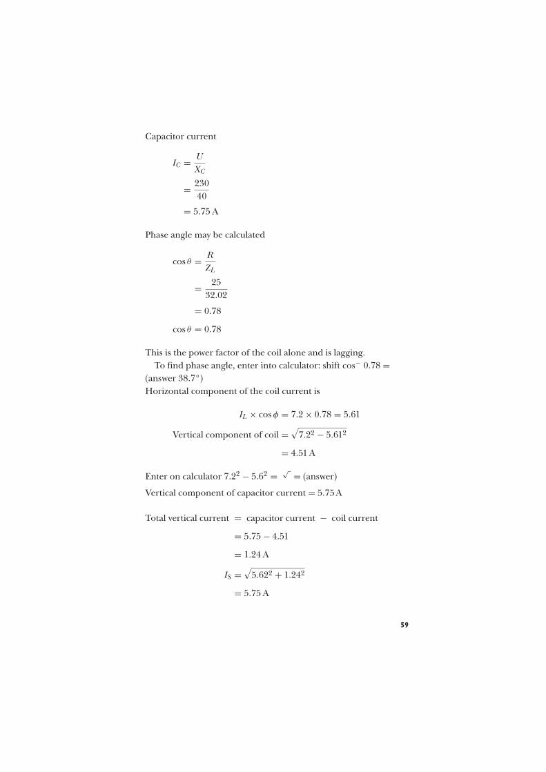
Capacitor current
IC = U
XC
= 230
40
= 5.75 A
Phase angle may be calculated
cos θ = R
ZL
= 25
32.02
= 0.78
cos θ = 0.78
This is the power factor of the coil alone and is lagging.
To find phase angle, enter into calculator: shift cos− 0.78 =(answer 38.7°)
Horizontal component of the coil current is
IL × cos φ = 7.2 × 0.78 = 5.61
Vertical component of coil =√
7.22 − 5.612
= 4.51 A
Enter on calculator 7.22 − 5.62 =√
= (answer)
Vertical component of capacitor current = 5.75A
Total vertical current = capacitor current − coil current
= 5.75 − 4.51
= 1.24 A
IS =√
5.622 + 1.242
= 5.75 A
59

kVA 50
kVAr
35 kW
38.8 kVA
0.7
0.9
θθ
Fig. 57
EXERCISE 8
1. Determine the current I in Figure 58 and state whether it
leads or lags the voltage U.
2. Determine the resultant current I and its phase relationship
with the supply voltage U in Figure 59. What is the power
factor of the circuit?
U~
I
C
L0.45 A
0.15 A
Fig. 58
U
I
L = 0.3 H
150 V 50 Hz
R = 50 Ω
Fig. 59
3. A capacitor of 15mF is connected in parallel with a coil of
inductance 0.3H and negligible resistance to a sinusoidal
supply of 240V 50Hz. Calculate the resultant current and
state whether the phase angle is a leading or lagging one.
4. Calculate the resulting supply current and the overall
power factor when a resistor of 100Ä is connected in
parallel with the circuit of question 3.
60

5. A coil of reactance 30Ä and resistance 40Ä is connected in
parallel with a capacitor of reactance 200Ä, and the circuit
is supplied at 200V. Calculate the resultant current and
power factor. Check the results by constructing the phasor
diagram accurately to scale.
6. A coil has resistance 150Ä and inductance 0.478H.
Calculate the value of a capacitor which when connected in
parallel with this coil to a 50Hz supply will cause the
resultant supply current to be in phase with the voltage.
7. An inductor coil of resistance 50Ä takes a current of 1A
when connected in series with a capacitor of 31.8mF to a
240V 50Hz supply. Calculate the resultant supply current
when the capacitor is connected in parallel with the coil to
the same supply.
8. The resultant current I in Figure 60 is
(a) 0.585A (b) 0.085A (c) 11.2A (d) 171A
9. The resultant current I in Figure 61 is
(a) 4A (b) 8.5A (c) 2.92A (d) 9.22A
U
I
L = 0.95 H
100 V 50 Hz
C = 8 µF
Fig. 60
C
R
U
I
IC = 1.5 A
IR = 2.5 A
~
Fig. 61
61

Power factor improvement
EXAMPLE 1 A consumer takes a load of 50kVA at 0.7 power
factor lagging. Calculate (a) the active and reactive components of
the load, (b) the leading kVAr taken from a capacitor to improve
the power factor to 0.9 lagging.
(a) Active component (true power)kW
kVA= pf
Transposed to find kW
kW × 0.7 = 35 kW
Reactive component kW2 = kVA2 = kVAr2
or kVAr =√
kW2 − kVA2
= 502 − 352
= 35.7 kVAr
(b) Leading kVAr required
kW
kVA= pf
Transposed for kVA
kW
0.9= 38.8
= 35
0.9= 38.8
kVAr =√
38.882 − 352
= 16.93 kVAr
Lagging kVAr − leading kVAr = kVAr taken by capacitor =35.7 − 16.93 = 18.77 kVAr
62

kVA = 50
kWA
C
B
O
φ1
φ2
Fig. 62
EXAMPLE 2 A test on an 80W fluorescent lamp circuit gave the
following results when connected to a 50 Hz mains supply.
Fig. 63
Without power factor improvement capacitor
Volts 232
Amperes 1.13
Watts 122
With power factor correction capacitor
Volts 232
Amperes 0.68
Watts 122
63

Calculate the value of the power factor correction capacitor in
microfarads (mF).
The in phase current of the circuit is calculated
I = P
U
= 122
232
= 0.525 A
This current is common to both cases since watts are the same.
U = 232 VAO
C
φ2
φ1
I2 = 0.68 A
I1 = 1.13 AB
Fig. 64
C A L C U L A T I O N W I T H O U T P . F .
C O R R E C T I O N
Current drawn from supply = 1.13A
Wattless current in the reactive component
=√
1.132 − 0.5252
= 1 A
Enter into calculator 1.132 X2 − 0.525 X2 = √ = (answer)
64

C A L C U L A T I O N W I T H P . F . C O R R E C T I O N
Current drawn from supply = 0.68A.
Wattless current in reactive component
=√
0.68 − 0.525
= 0.432 A
Difference between wattless current in circuit without capacitor
and circuit with power factor correction capacitor:
= 1 A − 0.432 A
= 0.568 A
Calculate reactance of capacitor
U = I × XC
232 = 0.568 × XC
Transpose for XC
232
0.568= 408 Ä
XC = 408 Ä
For capacitance in microfarads
XC = 106
2pfC
Transpose for C
C = 106
2pfXC
= 106
2 × 3.142 × 50 × 408
Enter into calculator EXP 6 ÷ (2 shift p × 50 × 408) = (answer)
= 7.8 mF
65

EXERCISE 9
1. The nameplate of a single-phase transformer gives its rating
as 5kVA at 230V. What is the full-load current that this
transformer can supply and what is its power output when
the load power factor is (a) 0.8, (b) 0.6?
2. (a) What is meant by power factor?
(b) The installation in a factory carries the following loads:
lighting 50kW, heating 30kW, and power 44 760W.
Assuming that the lighting and heating loads are
non-inductive, and the power has an overall efficiency of
87% at a power factor of 0.7 lagging, calculate (i) the total
loading in kW, (ii) the kVA demand at full load. (CGLI)
3. The current taken by a 230V 50Hz, single-phase induction
motor running at full load is 39A at 0.75 power factor
lagging. Calculate the intake taken from the supply
(a) in kW, (b) in kVA.
Find what size capacitor connected across the motor
terminals would cause the intake in kVA to be equal to the
power in kW. (CGLI)
4. A group of single-phase motors takes 50A at 0.4 power
factor lagging from a 230V supply. Calculate the apparent
power and the true power input to the motors. Determine
also the leading kVAr to be taken by a capacitor in order to
improve the power factor to 0.8 lagging.
5. A welding set takes 60A from a 230V a.c. supply at 0.5 p.f.
lagging. Calculate its input in (a) kVA, (b) kW.
Determine the kVAr rating of a capacitor which will
improve the power factor to 0.9 lagging. What total current
will now flow?
6. Explain with the aid of a phasor diagram the meaning of
power factor in the alternating-current circuit. Why is a low
power factor undesirable?
A single-phase load of 20kW at a power factor of 0.72 is
supplied at 240V a.c. Calculate the decrease in current if
the power factor is changed to 0.95 with the same kW
loading. (CGLI)
66

7. An induction motor takes 13A from the 240V single-phase
50Hz a.c. mains at 0.35 p.f. lagging. Determine the value of
the capacitor in microfarads which, when connected in
parallel with the motor, will improve the power factor to
0.85 lagging. Find also the supply current at the new power
factor.
8. A consumer’s load is 100kVA at 0.6p.f. lagging from a
240V 50Hz supply. Calculate the value of capacitance
required to improve the power factor as shown in the
table below:
Power factor 0.7 0.75 0.8 0.85 0.9 0.95 1.0
Capacitance required (mF)
9. An appliance takes a current of 45A at 0.2 power factor
lagging. Determine the current to be taken by a bank of
capacitors in order to improve the power factor to 0.6
lagging. Calculate the value of the capacitors in
microfarads if they are supplied at (a) 240V, (b) 415V, and
the supply frequency is 50Hz.
10. A test on a mercury vapour lamp gave the following
results:
Without power-factor-improvement capacitor:
volts 230 amperes 2.22 watts 260
With power-factor-improvement capacitor:
volts 230 amperes 1.4 watts 260
The supply frequency was 50Hz. Calculate the value of the
capacitor in microfarads.
11. A transformer is rated at 10kVA 230V. The greatest current
it can supply at 0.8 p.f. is
(a) 43.3A (b) 34.8A (c) 23A (d) 230A
12. The power output of the transformer of question 11 at
0.8 p.f. is
(a) 8kW (b) 12.5kW (c) 19.2kW (d) 3kW
13. A single-phase circuit supplies a load of 20kVA at 0.8 p.f.
lagging. The kVAr rating of a capacitor to improve the
power factor to unity is
(a) 16 (b) 12 (c) 25 (d) 33.3
67

14. In order to improve the power factor, a circuit requires a
capacitor to provide 6kVAr at 230V 50Hz. Its value in
microfarads is
(a) 1430mF
(b) 143mF
(c) 346mF
(d) 3460mF
68

Three-phase circuitcalculations
S T A R - C O N N E C T E D M O T O R S
Three-phase supplies to an installation are normally in-star
formation with an earthed star point. The earthed star point
provides a zero potential within the system to give a single phase
facility, as shown in Figure 65.
IP
IP
IL
IL
IL
IP
0 V
VP
VP
VP
VL
VL
VL
Fig. 65
The colour code and sequence for phases is L1 brown, L2 black,
L3 grey.
On a standard installation, the voltage between any two phases
is 400 volts, this is called the line voltage UL, and between any
phase and neutral the voltage will be 231 volts.
69

Calculation is
UP = UL√3
= 400√3
= 231 volts
The phasor for a balanced three-phase system is as Figure 66(b).
The current in a three-phase-star connected system is IL = IP .
As shown in Figure 65. IL is the current in any line and IP is the
current phase or load.
If the currents on a star-connected supply are the same on
each phase, the system is said to be balanced. Under these
circumstances, the current in the neutral is zero.
The power per phase is P
P = UP × IP
The total power is the sum of the power in each phase.
The total power in a balanced circuit can be calculated:
P =√
3UL IL
EXAMPLE A three-phase balanced load is connected in star,
each phase of the load has an impedance of 10 Ä. The supply is
400V 50Hz.
Calculate the current in each phase (IP ):
IP = UP
Z ×√
3
= 400
10 × 1.732
= 23 amperes per phase (in star IP = IL).
70

10Ω 10Ω
10Ω
(a) (b)
IL3IL
IL
IL
IP
IP
IP
IL2
IL1
Fig. 66
Calculate the total power in one phase:
P = UP × IP
= 231 × 23
= 5313 watts
Total power in all three phases 5313 × 3 = 15 939 watts.
Total power in all three phases can also be calculated.
P = UL × IL ×√
3
= 400 × 23 × 1.732
= 15 939 watts (15.9 kW).
D E L T A - C O N N E C T E D M O T O R S ( M E S H )
For delta-connected loads (Figure 67) the voltage across the load
will be the line voltage UL, and the line current, IL, will be the
phase current IP times√
3.
71

As a calculation
IL = IP ×√
3
IP
IP
IP
IP
IP
IP
IL
IL
VL
VL
VP
IL
Fig. 67
The total power under these conditions is P =√
3UL IL.
EXAMPLE (Using the same values as were used for star
connection)
A three-phase balanced load is connected in delta, each phase
of the load has an impedance of 10 Ä and the supply is 400 V
50Hz.
IP
IP
IP
IP
10Ω 10Ω
10Ω
IP
IP
IL
IL
IL
VL
VL
VP
Fig. 68
72

Calculate the phase current and the load current:
IP = UL
Z
= 400
10
IP = 40 A
IL = IP ×√
3
= 40 × 1.732
= 69.28 A
The total power can be calculated
P =√
3 × UL × IL
= 1.732 × 400 × 69.28
= 47 997 watts (47.8 kW).
It can be seen that the power dissipated in a delta-connected load
is three times that of the star-connected load. The same applies to
the current drawn from the supply.
R E S I S T A N C E A N D I N D U C T A N C E I N
T H R E E - P H A S E C I R C U I T S
In many three-phase loads such as motors, inductance as well as
resistance will need to be taken into account.
EXAMPLE 1 Three coils are connected in star formation to a
400 volt 50 Hz supply, each coil has a resistance of 35 Ä and an
inductance of 0.07 H.
Calculate (a) the line current IL and (b) the total power dissipated.
Step 1
Calculate inductive reactance
XL = 2pfL
= 2 × 3.142 × 50 × 0.07
= 22 Ä
73

An impedance triangle could be drawn if required as follows:
Draw to scale a line representing resistance on the horizontal
(opposite), at right angles to line R. Draw a line representing
inductive reactance (adjacent). The length of the hypotenuse will
represent the impedance Z.
ZXL
R
41.34Ω22Ω
35Ω
Fig. 69
By calculation
Z2 = X2L + R2
Z2 = 222 + 352
Z =√
222 + 352
= 41.34 Ä
Impedance (Z) is 41.34 Ä per phase.
Because the circuit has inductive reactance and resistance, the
load will have a power factor, this must now be calculated:
Power factor = R
Z
= 35
41.34
= 0.84
74

Line current can now be calculated
IL = UL
Z ×√
3(UL is line voltage)
= 400
41.34 × 1.732 × 0.84
= 5.59 A (in star IL = IP . Remember this is thecurrent per phase)
Power can now be calculated
P =√
3 × UL × IL × cos φ
= 1.732 × 400 × 5.59 × 0.84
= 3250 watts (3.25 kW)
EXAMPLE 2 Using the coils in the previous example connected
in delta, calculate the line current and total power dissipated.
In delta
IP = UL
Z × cos φ
= 400
41.34
IP = 9.68 A
IL = IP ×√
3
= 9.68 × 1.732
IL = 16.76 A (Note: three times the current in as in-star)
Power can now be calculated
P =√
3 × UL × IL × pf
= 1.732 × 400 × 16.76 × 0.84
= 9750 watts (9.75 kW) (Note: three times the
power as in-star)
75

EXERCISE 10
1. Three equal coils of inductive reactance 30 Ä and
resistance 40Ä are connected in-star to a three-phase
supply with a line voltage of 400V. Calculate (a) the line
current and (b) the total power.
2. The load connected between each line and neutral of a
400 V 50Hz three-phase circuit consists of a capacitor of
31.8 mF in series with a resistor of 100Ä. Calculate (a) the
current in each line and (b) the total power.
3. The load connected between each line and the neutral of a
400V three-phase supply consists of:
(a) Between L1 and N, a noninductive resistance of 25Ä
(b) Between L2 and N, an inductive reactance of 12Ä
in series with a resistance of 5Ä
(c) Between L3 and N, a capacitive reactance of 17.3Ä in
series with a resistance of 10Ä.
Calculate the current in each phase.
4. Three resistors each of 30Ä are connected in-star to a
400V three-phase supply. Connected in-star to the same
supply are three capacitors each with a reactance of 40Ä.
Calculate (a) the resultant current in each line and (b) the
total power.
5. Three capacitors, each with a reactance of 10Ä are to be
connected to a three-phase 400V supply for power factor
improvement. Calculate the current in each line if they are
connected (a) in-star, (b) in-mesh.
6. A 440V, three-phase, four-wire system supplies a balanced
load of 10kW. Three single-phase resistive loads are added
between lines and neutrals as follows: (a) L1–N 2 kW,
(b) L2–N 4 kW, (c) L3–N 3 kW. Calculate the current in
each line.
7. Three 30Ä resistors are connected (a) in-star, (b) in-delta to
a 400V three-phase system. Calculate the current in each
resistor, the line currents and the total power for each
connection.
76

8. Each branch of a mesh connected load consists of a
resistance of 20Ä in series with an inductive reactance of
30Ä. The line voltage is 400V. Calculate (a) the line
currents and (b) total power.
9. Three coils each with a resistance of 45Ä and an
inductance of 0.2H, are connected to a 400V three-phase
supply at 50Hz, (a) in-mesh (b) in-star. Calculate (i) the
current in each coil and (ii) the total power in the
circuit.
10. A three-phase load consists of three similar inductive coils,
each with a resistance of 50Ä and an inductance of 0.3H.
The supply is 400V 50Hz. Calculate (i) the current in each
line, (ii) the power factor, (iii) the total power, when the
load is (a) star-connected, (b) delta-connected.
11. Three equal resistors are required to absorb a total of
24kW from a 400V three-phase system. Calculate the value
of each resistor when they are connected (a) in-star,
(b) in-mesh.
12. To improve the power factor, a certain installation requires
a total of 48kVAr equally distributed over the three phases
of a 415V 50Hz system. Calculate the values of the
capacitors required (microfarads) when the capacitors are
connected (a) in-star (b) in-delta.
13. The following loads are connected to a three-phase 400V
50Hz supply. A noninductive resistance of 60Ä is
connected between L1 and L2, an inductive reactance of
30Ä is connected between L2 and L3, and a capacitor of
100mF is connected between L1 and L3. Calculate the total
power and the current through each load.
14. A motor generator set consists of a d.c. generator driven by
a three-phase a.c. motor. The generator is 65% efficient and
delivers 18A at 220V. The motor is 75% efficient and
operates at 0.5p.f. lagging from a 415V supply. Calculate
(a) the power output of the driving motor, (b) the line
current taken by the motor.
15. A conveyor raises 1600kg of goods through a vertical
distance of 5m in 20 s. It is driven by a gear which is
77

55% efficient. Calculate the power output of the motor
required for this work. If a three-phase 400V motor with
an efficiency of 78% is fitted, calculate the line current
assuming a power factor of 0.7.
16. A 415V three-phase star-connected alternator supplies a
delta-connected induction motor of full load efficiency 87%
and a power factor of 0.8. The motor delivers 14920W.
Calculate (a) the current in each motor winding, (b) the
current in each alternator winding, (c) the power
developed by the engine driving the alternator, assuming
that the alternator is 82% efficient.
17. A three-phase transformer supplies a block of flats at 230V
line to neutral. The load is balanced and totals 285 kW at
0.95 power factor. The turns ratio of the transformer,
primary to secondary is 44:1 and the primary side of the
transformer is connected in mesh. Calculate the primary
line voltage. Draw a diagram and mark the values of the
phase and line currents in both windings.
T H R E E - P H A S E C I R C U I T S
In a balanced three-phase circuit no current will flow in the
neutral. In an unbalanced three-phase circuit, some current will
flow in the neutral, this current can be calculated by using four
different methods.
EXAMPLE 1 A sub-main supplying an unbalanced three-phase
and neutral distribution board has currents of 75A in L1 (brown),
55 A in L2 (black) and 40 A in L3 (grey). Calculate the current in
the neutral.
Draw L1, L2 and L3 to scale at 120° to each other.
Now draw a vertical line from the end of L2 the same length as L1.
Then join the tops of L1 and L2.
Draw a line between the shortest angles of the parallelogram. Now
draw a line the same length and parallel with L3 from the top left
angle. Join the ends of L3 and the line parallel to it. Measure the
78

5540
75
N
Fig. 70
gap between the shortest angle and, if the phasor is drawn to
scale, this will be the current flowing in the neutral.
EXAMPLE 2 Using a triangle, draw a horizontal line to scale to
represent L1.
75
5540
N
Fig. 71
From the right-hand side of this line, draw a line at 120° to it to
scale to represent L2. Now draw a line from the end of L2 at 120°
to it to represent L3 to scale.
Measure the gap between the open ends of L1 and L3, this will be
the current flowing in the neutral.
EXAMPLE 3 Using a simpler phasor diagram and a simple
calculation.
Take the smallest current from the other two currents.
79

In this example L3 (40A) is the smallest current.
(L1) 75 A − 40 A = 35 A
(L2) 55 A − 40 A = 15 A
Draw a vertical line to scale to represent corrected L1.
15
35
N
Fig. 72
Now draw a line to scale at 120° to it to represent corrected L2.
Draw a line vertically from the end of L2 the same length as L1,
join open ends.
Measure between the shortest angles and this will be the current
in the neutral.
EXAMPLE 4 By calculation only
Subtract the smallest current from the other two.
(L1) 75 A − (L3) 40 A = 35 A
(L2) 55 A − (L3) 40 A = 15 A
Current in the neutral can now be calculated (this will not be exact
but very close):
√
352 − 152 = 31.62
EXERCISE 11
1. Three separate single-phase loads are to be connected to a
three-phase and neutral supply, the currents in the loads are
as follows: L1 = 32A, L2 = 24 A and L3 = 30A. Calculate the
current flowing in the neutral.
80

2. A submain is to be installed to supply the following loads.
L1 is a lighting load of 3.2 kW, L2 is a cooker load of 7 kW,
L3 is supplying a 20A power load. The supply voltage is
230V 50Hz.
3. Calculate the current flowing in the neutral conductor of a
supply cable when the following currents are flowing in the
phase conductors: L1 = 10A, L2 = 30A, L3 = 20A.
T H R E E - P H A S E P O W E R
The chapter entitled Power factor in Book 1 explains leading and
lagging power factor. In this chapter, we will take power factor a
step further and see how it affects three-phase circuits.
It is often simpler to draw a power triangle showing:
Active power or true power in watts (W) or kW.
Apparent power in volt amps (VA) or kVA.
Reactive power in VAr or kVAr.
Power factor cos φ is found
kW
kVAr
kVA leading
kVAr
kW
φ
Fig. 73
Leading power factor
81

kVA laggingkVAr
kW
φ
Fig. 74
Lagging power factor
To find the true power, apparent power and the reactive power
we must first calculate as follows:
EXAMPLE 1 A three-phase motor with an output of 2.8 kW and
a power factor of 0.89 (p.f.) is connected to a 400 V 50 Hz supply.
Calculate:
(a) the power drawn from the supply
(b) the reactive power
(c) the line current
(a) p.f. = kW
kVA
Transposed
kVA = kW
p.f.
= 2.8
0.89
= 3.14 kVA (power drawn from supply is greater than
the power delivered by the motor)
(b) kVAr2 = kVA2 − kW2 or
kVAr =√
kVA2 − kW2
=√
3.142 − 2.82
= 1.42 kVAr
82

Enter into calculator
3.14X2 − 2.8X2 = √ = (answer)
(c) Line current calculation
P =√
3ULIL cos φ
= W√3 × UL × cos φ
Transposed
= 2800√3 × 400 × 0.89
= 4.54 A
EXAMPLE 2 A commercial building is supplied by a three-phase,
four-wire 400 V 50 Hz supply and the phases are loaded as follows:
L1 is taking 35 kW at unity power factor
L2 is taking 40 kVA at 0.8 lagging power factor
L3 is taking 60 kVA at 0.7 leading power factor
Calculate the power factor for the system.
Phase L1 is unity power factor
p.f. = kW true power
kVA apparent power
Transposed
kVA = kW
p.f.
= 35
1
= 35 kVA
This phase has no reactive power.
83

The circuit is purely resistive and can be shown by phasor as
I
V
Fig. 75
Phase L2 has a power factor of 0.8 lagging.
Using formulae
p.f. = kW
kVA
Transposed to find kW
= p.f. × kVA
= 0.8 × 40
= 32 kW
Reactive (kVAr) power can be calculated
kVAr =√
kVA2 − kW2
=√
402 − 322
= 24 kVAr.
The circuit is inductive (lagging) and can be shown by phasor as:
V
I
Fig. 76
84
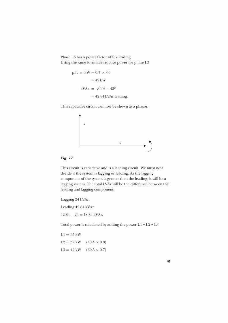
Phase L3 has a power factor of 0.7 leading.
Using the same formulae reactive power for phase L3
p.f . × kW = 0.7 × 60
= 42 kW
kVAr =√
602 − 422
= 42.84 kVAr leading.
This capacitive circuit can now be shown as a phasor.
V
I
Fig. 77
This circuit is capacitive and is a leading circuit. We must now
decide if the system is lagging or leading. As the lagging
component of the system is greater than the leading, it will be a
lagging system. The total kVAr will be the difference between the
leading and lagging component.
Lagging 24 kVAr
Leading 42.84 kVAr
42.84 − 24 = 18.84 kVAr.
Total power is calculated by adding the power L1 + L2 + L3
L1 = 35 kW
L2 = 32 kW (40A × 0.8)
L3 = 42 kW (60A × 0.7)
85

Total power 109 kW.
Total reactive component 18.84 kVAr (leading).
kVA can now be calculated
√
18.842 + 1092
= 110.60 kVA
Power factor can now be calculated
p.f. = kW
kVA
= 109
110.60
= 0.98
V O L T A G E D R O P I N T H R E E - P H A S E
C I R C U I T S
The method explained here is not a rigid treatment of three-phase
voltage drop, but will provide a result which will be sufficient for
most purposes (reactance is not taken into account).
BS 7671 allows a maximum voltage drop in an installation of 4%
for each circuit. This is to be measured from the supply intake to
the furthest point of the circuit. In most installations the line
voltage (UL) of a three-phase supply is 400 volts.
4% of 400 = 16 volts.
If the three-phase circuit is not a balanced load, each phase should
be calculated as a single-phase circuit
4% of 230 = 9.2 volts
EXAMPLE 1 A three-phase balanced load of 15 A per phase is
supplied by a steel wire armoured cable with a c.s.a. of 2.5mm2. The
volt drop for this cable is 15mV/A/m and the circuit is 30 m long.
Calculate (a) the voltage drop in the cable and (b) determine
if it complies with the voltage drop requirements of BS 7671.
86

(a) Volt drop = mV × I × L
1000
= 15 × 15 × 40
1000
= 9 V per phase
The equivalent voltage drop in line voltage is
=√
3 × 9
= 15.58 volts
(b) This complies as it is less than 16 V.
EXAMPLE 2 A three-phase 10kW motor operates on full load
with efficiency 80% and power factor 0.75. It is supplied from a
switchboard through a cable each core of which has resistance
0.2 Ä. Calculate the voltage necessary at the supply end in order
that the voltage at the load end terminals shall be 400V.
The full load current of the motor is
I = 10 × 1000√3 × 400 × 0.75
× 100
80
= 24.06 A
The voltage drop per core of the cable
= 24.06 × 0.2
= 4.8 V
The equivalent reduction in the line voltage
=√
3 × 4.8
= 8.31 V
The required the voltage at the switchboard
= 400 + 8.31
= 408.3 V
This is not a rigid treatment of the problem but the method
gives a result sufficiently accurate for most practical purposes.
87

EXAMPLE 3 The estimated load in a factory extension is 50kW
balanced at 0.8 p.f. The supply point is 120 metres away and the
supply voltage is 400V. Calculate the cross-sectional area of the
cable in order that the total voltage drop shall not exceed 2.5% of
the supply voltage.
Take the resistivity of copper as 1.78 × 10⁻⁸ Äm.
The line current
I = 50 × 1000√3 × 400 × 0.8
= 90.21 A
Allowable reduction in line voltage
= 2.5% × 400
= 10 V
Equivalent reduction in phase voltage
= 10√3
= 5.77 V
Resistance per core of the cable
= 5.77
90.21
= 0.06 396 Ä
The resistance of a cable is given by
R = ρl
A
where ρ is the resistivity (Äm)
l is the length (m)
A is the cross-sectional area (m2)
88

so that
A = ρl
R
A = 1.78 Äm × 120 m
108 × 0.06396 Ä
= 0.33
104m2
= 0.33
104m2
[
106mm2
1m2
]
= 33 mm2
EXAMPLE 4 A p.v.c. trunking is to be used to enclose single-
core p.v.c.-insulated distribution cables (copper conductors) for a
distance of 30m from the main switchgear of an office building to
supply a new 400V T.P. and N distribution fuseboard. The
balanced load consists of 24kW of discharge lighting. The fuses at
the main switch-fuse and at the distribution board are to BS 88
part 2. The voltage drop in the cables must not exceed 6V. The
ambient temperature is anticipated to be 35 C. The declared
value of Ip is 20kA and that of Ze is 0.30 Ä. Assume that the
requirements of BS 7671 434-03 are satisfied by the use of BS 88
fuses.
(a) For the distribution cables, establish the:
(i) design current (Ib)
(ii) minimum rating of fuse in the main switch-fuse (In)
(iii) maximum mV/A/m value
(iv) minimum current rating (It)
(v) minimum cross-sectional area of the live conductors
(vi) actual voltage drop in the cables.
(b) It is proposed to install a 2.5mm2 protective conductor within
the p.v.c. trunking. Verify that this meets shock protection
requirements. (C & G)
89

(a) (i) Design current Ib = 24 × 103 × 1.8√3 × 400
(1.8 factor for
discharge lighting)
= 62.36A
(ii) Minimum BS 88 fuse rating (In) is 63A.
(iii) Maximum mV/A/m value = 6 × 1000
62.36 × 30
= 3.2mV/A/m
(iv) Minimum current rating (It) = 63
0.94
(temperaturecorrection factorCa for 35°C)
= 67.02A
(v) Minimum c.s.a. of cable is 16mm2 (68A 2.4mV/A/m).
(vi) Actual voltage drop in 30m= 2.4 × 62.36 × 30
1000=4.49V
(b) Check compliance with Table 41D (BS 7671) using IEE On-Site
Guide.
From Table 9A, R1 + R2 for 16 mm2/2.5 mm2 = 1.15 + 7.41 mÄ/m.
From Table 9C, factor of 1.20 must be applied.
Now Zs = Ze + R1 + R2
R1 + R2 = 30 × (1.15 + 7.41) × 1.20
1000
= 0.308 Ä
∴ Zs = 0.3 + 0.308
Zs = 0.608 Ä
This satisfies Table 41D as the maximum Zs for a 63A fuse is
0.86 Ä.
EXAMPLE 5 It is proposed to install a new 230V 50Hz
distribution board in a factory kitchen some 40m distant from the
supplier’s intake position.
It is to be supplied by two 25mm2 p.v.c. insulated (copper
conductors) single-core cables in steel conduit. Protection at
origin of the cables is to be by BS 88 fuses rated at 80A.
90

It is necessary for contractual purposes to establish:
(a) the prospective short circuit current (p.s.c.c.) at the
distribution board, and
(b) that the proposed distribution cables will comply with
BS 7671 requirements 434-03-03.
A test conducted at the intake position between phase and neutral
to determine the external impedance of the supplier’s system
indicates a value of 0.12 Ä.
(a) The resistance of distribution cables from intake to
distribution board
From Table 9A (IEE On-Site Guide), R1/R2 for 25mm2/25mm2
cables = 1.454mV/m.
From Table 9C a multiplier of 1.20 is necessary using the Table 6A
figures as
R1/R2 = 40 × 1.454 × 1.20
1000
= 0.0698 Ä (regard this as impedance)
So total short circuit fault impedance = 0.12 + 0.0698
= 0.19 Ä
Thus If = 230
0.19∴ p.s.c.c. = 1210A
From Appendix 3, Figure 3.3A, the BS 88 fuse clearance time is
approximately 0.1s.
(b)From Requirement 434-03-03, t = k2S2
I2
= 1152 × 252
12002
∴ limiting time for conductors (t) = 5.74 s
The cables are disconnected well before the 25mm2 cable
conductors reach their limiting temperature, thus they are
protected thermally.
91

EXAMPLE 6 Two 25mm2 single-core p.v.c.-insulated cables
(copper conductors) are drawn into p.v.c. conduit along with a
10mm2 protective conductor to feed a 230V industrial heater.
The following details are relevant:
Protection at the origin is by 80A BS 88 fuses.
The tested value of Ze at the cables origin is 0.35 Ä.
The length of cables run is 55m.
(a) Establish the:
(i) value of R1 + R2 of the cables
(ii) prospective earth fault loop current (Ief )
(iii) the disconnection time of the fuse.
(b) Does the clearance time comply with BS 7671?
(a) (i) Using the IEE On-Site Guide
From Table 9A R1 + R2 for 25 mm2/10 mm2 cables =2.557 mÄ/m. From Table 9C apply the factor 1.20
Thus R1 + R2 = 55 × 2.557 × 1.20
1000
= 0.169 Ä
So Zs at distribution board = 0.35 + 0.169
= 0.519 Ä
(ii) Prospective earth fault current (Ief ) = 230
0.519
= 443A
(iii) Using BS 7671, Appendix 3, Table 3.3A, disconnection time
is 3.8s.
(b) The clearance time complies with BS 7671 Requirement
413-02-13 which specifies a maximum disconnection time of 5s.
EXAMPLE 7 It is necessary to confirm that the cross-sectional
area of the protective conductor in a previously installed 400/230V
distribution circuit complies with BS 7671 requirement 543-01-03.
The phase conductors are 10mm2 and the circuit-protective
conductor is 2.5mm2. The length of the cables run in plastic
92

conduit is 85m. Protection by 32A, BS 88 fuses and the value of Ze
is 0.4 Ä.
Using the IEE On-Site Guide
From Table 9A R1 + R2 for 10 mm2/2.5 mm2
cables = 1.83 + 7.41 mÄ/m
From Table 9C apply the factor 1.20
Thus R1 + R2 = 85 × (1.83 + 7.41) × 1.20
1000
= 0.942 Ä
So Zs at distribution board = 0.4 + 0.942
= 1.342Ä
Prospective earth fault loop current (Ief ) = 230
1.342
= 171A
Using BS 7671
From Appendix 3 Table 3.3A, the fuse clearance time is 0.9s.
From BS 7671 requirement 543-01-03
s =√
I2t
k(k is 115 Table 54C)
=√
1712 × 0.9
115
= 1.41 mm2
This confirms that a 2.5mm2 protective conductor is acceptable.
EXAMPLE 8 The declared value of Ip at the origin of a 230V
50Hz installation is 1.5kA. The length of 25mm2 p.v.c./p.v.c.
metre tails is 2m; at this point a switch-fuse containing 100A
BS 88 Part 2 fuses is to be installed to provide control and
protection for a new installation. A 20m length of 16mm2 heavy
duty mineral insulated cable (exposed to touch), (copper
conductors and sheath) is to be run from the switch-fuse to a new
distribution board.
93

(a) Establish that the mineral cable complies with BS 7671
requirement 434-03.
(b) How could you ensure that the requirements of BS 7671
413-02-01, etc. and Chapter 7 are satisfied?
(a) Resistance of 2m of 25mm2 metre tails using mV/A/m value
from Table 9D1A as ohms per metre at 70°C
Rmt = 2 × 0.00175
= 0.0035 Ä
Resistance of 20m of 16mm2 twin m.i.c.c. cable using mV/A/m
values from Table 4JB as ohms per metre at 70°C
Rmi = 20 × 0.0026
= 0.052 Ä
Impedance of supply = 230
1500
= 0.153 Ä
Thus total impedance from source to distribution board
= 0.153 + 0.0035 + 0.052 = 0.2085 Ä
Prospective short circuit fault current
Ip = 230
0.2085= 1103 A
Disconnection time from BS 7671 Table 3.3B is 0.3s
Now using the 434-03-03 adiabatic equation
t = k2S2
I2
= 1352 × 162
11032
= 3.8 s
Thus 16mm2 cable is protected against the thermal deterioration.
94

(b) As no details are available in BS 7671 in relation to the
resistance/impedance of the m.i.c.c. sheath, the prospective
value of Zs could not be established, but the actual value must be
tested when the installation is commissioned and the value
recorded in the Electrical Installation Certificate referred to in
requirement 742.
EXAMPLE 9 A 230V, 50Hz, 5kW electric motor is fed from a
distribution board containing BS 88 Part 2 fuses. The wiring
between the d.f.b. and the motor starter which is 20m distant is
p.v.c.-insulated single-core cables drawn into steel conduit.
Assume that the:
(i) starter affords overload protection;
(ii) motor has a power factor of 0.75 and an efficiency of 80%;
(iii) ambient temperature is 40°C;
(iv) fuse in the d.f.b. may have a rating up to twice the rating of
the circuit cables;
(v) volts drop in the motor circuit cables must not exceed 6V;
(vi) resistance of metal conduit is 0.1 Ä per metre;
(vii) ‘worst’ conduit run is 8m with two 90° bends;
(viii) Ip at d.f.b. is 2kA;
(ix) value of Ze is 0.19 Ä.
Establish the:
(a) design current (Ib);
(b) rating of circuit fuse;
(c) minimum cable rating (In) between d.f.b. and starter;
(d) minimum cable cross-sectional area;
(e) actual voltage drop in cables;
(f ) prospective short circuit current;
(g) short circuit disconnection time;
(h) whether BS 7671 requirement 434-03-03, etc. is satisfied;
(i) whether BS 7671 requirement 413-02-04, etc. is satisfied;
( j) minimum conduit size.
(a) Design current (Ib) = 5000
230 × 0.75 × 0.8
= 36.2 A
95

(b) Rating of circuit fuse may be 80A.
(c) Minimum cable rating may be 40A.
(d) Minimum cable c.s.a. = 40
0.87= 46 A
from Table 4D1A select 10mm2 cable (57A).
(e) Actual voltage drop:
from Table 4D1BmV/A/m value for 10mm2 is 4.4 thus
volts drop = 36.2 × 20 × 4.4
1000
= 3.19 V
(f ) Impedance of supply cables to d.f.b.
= 230
2000= 0.115 Ä
Using BS 7671 Tables 9A and 9C, resistance of circuit cables
= 20 × 3.66 × 1.2
1000
= 0.09 Ä
thus total circuit impedance = 0.115 + 0.09 = 0.205 Ä
Prospective short circuit current = 230
0.205
= 1122 A
(g) Disconnection time from Figure 3.3A is 0.1s
(h) Cable thermal capacity t = k2 × S2
I2
= 1152 × 102
11222
= 1.05 s
Thus 10mm2 cables are thermally safe.
96

(i) Now Zs = Ze + R1 + R2
Using BS 7671 Tables 9A and 9C,
Resistance of R1 = 20 × 1.83
1000= 0.0366 Ä
Resistance of conduit R2 = 20 × 0.01 = 0.2 Ä
Thus Zs = 0.19 + 0.0366 + 0.2 = 0.4266 Ä
Ief = 230
0.4266= 539 A
From BS 7671, Figure 3.3A, disconnection time is 1.4s; this
being less than 5s, protection is satisfactory.
( j) From Table 5C,
cable factor for 2 × 10 mm2cables = 2 × 105 = 210
From Table 5D select 25mm conduit (factor 292).
EXERCISE 12
1. A balanced load of 30A is supplied through a cable each
core of which has resistance 0.28 Ä. The line voltage at
the supply end is 400V. Calculate the voltage at the load
end, the percentage total voltage drop and the power
wasted in the cable.
2. Each core of a three-core cable, 164m long, has a
cross-sectional area of 35mm2. The cable supplies power
to a 30kW, 400V, three-phase motor working at full load
with 87% efficiency and power factor 0.72 lagging.Calculate:
(a) the voltage required at the supply end of the cable;(b) the power loss in the cable.
The resistivity of copper may be taken as
1.78 × 10⁻⁸ Äm and the reactance of the cable may be
neglected.3. A 40kW, 400V, three-phase motor, running at full load,
has efficiency 86% and power factor 0.75 lagging. The
three-core cable connecting the motor to the switchboard
is 110m long and its conductors are of copper 25mm2 in
cross-section.Calculate the total voltage drop in the cable, neglecting
reactance.
97

If the cable runs underground for most of its length,
choose a suitable type of cable for the purpose and give a
descriptive sketch of the system of laying it.
The resistivity of copper may be taken as 1.78 × 10⁻⁸ Äm.
4. The estimated load in a factory extension is 200kW at
0.85p.f. (balanced). The supply point is 75m away where
the line voltage is 400V. Choose the most suitable size of
cable from those given below in order that the total voltage
drop shall not exceed 2.5% of supply voltage.
Cross-sectional areas
of available conductors (mm2) 35 50 70 95
(Resistivity of conductor is 1.78 × 10⁻⁸ Äm.)
5. A motor taking 200kW at 0.76p.f. is supplied at 400V
three-phase by means of a three-core copper cable
200m long.
(a) Calculate the minimum cable cross-sectional area if
the voltage drop is not to exceed 5V.
(b) If the cable size calculated is non-standard, select from
the table a suitable standard cable and calculate the
actual voltage drop using that cable.
Standard cross-sectional areas of cable conductors (mm2)
300 400 500 630
(Resistivity of copper 1.78 × 10⁻⁸ Äm.)
6. A three-phase current of 35A is supplied to a point 75m
away by a cable which produces a voltage drop of 2.2mV
per ampere per metre. Calculate the total voltage drop.
The following question should be answered by reference to
be appropriate tables in BS 7671 and/or in the IEE On-Site
Guide to BS 7671.
7. A balanced load of 85A is required at a point 250m distant
from a 400V supply position. Choose a suitable cable
(clipped direct) from Tables 4E4A and 4E4B in order that
the total voltage drop shall be within the BS 7671 specified
limit (ambient temperature 30°C).
8. A 25kW, 400V three-phase motor having full load
efficiency and power factor 80% and 0.85 respectively is
98

supplied from a point 160m away from the main
switchboard. It is intended to employ a surface-run,
multicore p.v.c.-insulated cable, non-armoured (copper
conductors). The ambient temperature is 30°C and BS 88
fuses are to be employed at the main switchboard. Select a
cable to satisfy the BS 7671 requirements.
9. The total load on a factory sub-distribution board
consists of:
10kW lighting balanced over three phases, unity power
factor; 50kW heating balanced over three phases, unity
power factor and 30kW motor load having an efficiency
80%, power factor 0.8.
The line voltage is 400V and the supply point is 130m
distant. Protection at the origin of the cable (clipped direct)
is by BS 88 fuses. The ambient temperature is 30°C.
Select a suitable cable from Tables 4D2A and 4D2B, in
order that the voltage drop shall not exceed 3% of the
supply voltage.
10. Calculate the additional load in amperes which could be
supplied by the cable chosen for question 9 with the voltage
drop remaining within the specified limits.
11. A 12kW, 400V three-phase industrial heater is to be wired
using single-core p.v.c.-insulated cables (copper conductors)
30m in length drawn into a steel conduit. The following
details may be relevant to your calculation.
Ambient temperature 40°C
Protection by BS 3036 (semi-enclosed) fuses.
Voltage drop in the cables must not exceed 10V.
The contract document calls for a 2.5mm2 conductor to
be drawn into the conduit as a supplementary protective
conductor.
The worst section of the conduit run involves two
right-angle bends in 7m. Establish the:
(a) design current (Ib);
(b) minimum fuse rating (In);
(c) maximum mV/A/m value;
(d) minimum live cable rating (It);
99

(e) minimum live cable c.s.a.;
(f) actual voltage drop;
(g) minimum conduit size.
12. The external live conductor impedance and external earth
fault loop impedance are tested at the intake of a 230V
single-phase installation and show values of 0.41 Ä and
0.28 Ä, respectively. A p.v.c. trunking runs from the intake
position to a distribution board 40m distant and contains
35mm2 live conductors and a 10mm2 protective conductor.
(a) Estimate the:
(i) prospective short circuit current (p.s.c.c.) at the
distribution board;
(ii) p.s.c.c. clearance time of the 100A BS 88 fuse at
the origin of the cable;
(iii) value of the earth fault loop impedance (Zs) at
the distribution board;
(iv) prospective earth fault loop current;
(v) earth fault clearance time of the BS 88 fuse at the
origin of the cable.
(b) State the maximum permitted value of Zs under these
conditions.
13. A p.v.c. trunking containing single-core p.v.c.-insulated
distribution cables (copper conductors) is to be run 30m
from the 400/230V main switchgear of an office building
to supply a new T.P. and N distribution fuseboard. The
balanced load consists of 24kW of discharge lighting. The
fuses at the main switch-fuse and at the distribution board
are to BS 88 part 2. The voltage drop in the distribution
cables must not exceed 6V and the ambient temperature is
anticipated to be 35°C. The declared value of Ip is 20kA
and that of Ze is 0.3 Ä. Assume that the requirements of
BS 7671 434-5 are satisfied.
(a) For the distribution cables, establish and state the
(i) design current;
(ii) minimum rating of fuse in the main switch fuse;
100

(iii) maximum mV/A/m value;
(iv) minimum current rating;
(v) minimum cross-sectional area of the live
conductors;
(vi) actual voltage drop in the cable.
(b) It is proposed to install a 4mm2 protective conductor
within the p.v.c. trunking.
(i) State the value of Zs.
(ii) Verify that this meets BS 7671 shock protection
requirements.
14. A security building is to be built at the entrance to a factory.
This new building is to be provided with a 230V single-
phase supply and is to be situated 20m from the main
switchroom. A 30m twin p.v.c.-insulated armoured
underground cable (copper conductors) supplies the new
building, which allows 5m at each end for runs within the
main switchroom and security buildings. The connected
load in the security building comprises
one 3kW convector heater
two 1kW radiators
two 1.5kW water heaters (instantaneous type)
one 6kW cooker
six 13A socket outlets (ring circuit)
a 2kW lighting load.
Diversity may be applied (business premises).
Establish:
(a) the prospective maximum demand;
(b) minimum current rating of the switch-fuse in the
switchroom at the origin of the underground cable.
(c) Determine
(i) the minimum current rating of p.v.c.-insulated
twin armoured (copper conductor) underground
cable, assuming an ambient temperature of 25°C
and protection to be by BS 88 part 2 devices;
(ii) the minimum size of cable, assuming the voltage
drop is limited to 2V;
(iii) the actual voltage drop in the cable. (C & G)
101

15. It is proposed to install a p.v.c.-insulated armoured cable to
feed a 25kW, 400V, three-phases 50Hz resistive element
type of furnace. The cable is to be surface run along a brick
wall of a factory and has a total length of 95m. The
protection at the origin of the circuit is to be by BS 88
fuses. The cable armour may be relied upon as the circuit
protective conductor. The ambient temperature in the
factory will not exceed 35°C and the voltage drop must not
exceed 10V.
Determine and state the:
(a) design current;
(b) fuse rating;
(c) minimum cable current rating;
(d) maximum mV/A/m value;
(e) minimum cross-sectional area of the live conductors;
(f) actual voltage drop in the cable. (C & G)
16. A pipeline pump is connected to a 400/230V three-phase
supply. It is wired in 1.5mm2 p.v.c.-insulated cables drawn
into 25mm steel conduit running 30m from a distribution
board containing BS 88 part 2 fuses (10A fuses protect the
pump).
It is now necessary to add alongside the pump a 12kW
400/230V heater and it is proposed to draw the
p.v.c.-insulated cables into the existing 25mm pump circuit
conduit and insert suitable fuses into the distribution
board which has vacant ways.
The following assumptions may be made:
(i) an ambient temperature of 35°C;
(ii) the maximum distance between draw in boxes is 9.5m
with two right-angle bends;
(iii) the maximum voltage drop in the heater circuit is 5V;
(iv) a 2.5mm2 protective conductor is installed in the steel
conduit to satisfy a clause in the electrical
specifications.
102

Determine for the heater circuit the:
(a) design current Ib;
(b) suitable fuse rating In;
(c) maximum mV/A/m value;
(d) minimum cable current rating It;
(e) minimum cable c.s.a.;
(f) actual voltage drop.
For the existing pump circuit establish whether the:
(g) pump circuit cable current rating is still adequate;
(h) 25mm conduit is suitable for the additional cables.
103

Voltmeters and ammeters:changing the use andextending the range
V O L T M E T E R S
The voltmeter is a high-resistance instrument and its essential
electrical features may be represented by the equivalent circuit of
Figure 78.
Movement
Electrical resistanceof movement
Additional seriesresistance as required
B
A
Ri
Rs
Fig. 78
Ri is the ‘internal resistance’ of the movement, i.e. the
resistance of the moving coil or the resistance of the fixed coil in
the case of a moving-iron instrument.
Independently of its resistance, the movement will require a
certain current to deflect the pointer across the full extent of the
scale against the effect of the controlling springs. This is the
current required for full-scale deflection (f.s.d.).
104

The range of voltage which the instrument can indicate is
governed by the total resistance R as measured between the
terminals A and B, and
R = Ri + Rs
If If .s.d. is the current required to produce full-scale deflection
and R is the total resistance between A and B, the voltage between
A and B at full-scale deflection is
U = R × If .s.d.
If .s.d. is fixed by the mechanical and electrical characteristics of
the instrument and is not normally variable. The resistance R,
however, can be fixed at any convenient value by adding the
additional series resistance (Rs) as required.
EXAMPLE An instrument has internal resistance 20 Ä and gives
f.s.d. with a current of 1mA. Calculate the additional series
resistance required to give f.s.d. at a voltage of 100V.
U = R × If .s.d.
∴ 100 = R × 1
1000(note the conversion of milliamperesto amperes)
∴ R = 100 × 1000 Ä
= 100 000 Ä
But the instrument has internal resistance of 20 Ä; thus the
additional resistance required is
Rs = R − Ri
= 100 000 − 20
= 99 980 Ä
(Note that this is a somewhat unrealistic value in terms of what it is
economically practical to manufacture. In practice, the additional
105

resistance would be constructed to the nominal value of 100 000 Ä
(100 kÄ) and slight adjustments would be made as necessary at the
calibration stage to obtain f.s.d. with an applied 100V.)
Any applied voltage less than 100V of course produces a
corresponding lower reading on the instrument.
The additional series resistor Rs is also known as a multiplier.
A M M E T E R S
The ammeter is a low-resistance instrument, and its equivalent
electrical circuit is shown in Figure 79.
I (the current to
be measured)
Movement
Rp
Ri
I
Fig. 79
The resistor Rp connected in parallel is the ‘shunt’ through
which most of the current to be measured flows. Its value will be
low compared with the internal resistance of the movement Ri.
The calculation of Rp proceeds as follows.
Knowing Ri and the current required to give f.s.d., determine
the voltage required to produce f.s.d. of the movement. For
example, using the information of the previous example
(If .s.d. =1mA and Ri = 20 Ä),
p.d. required for f.s.d. = Uf .s.d. = If .s.d. × Ri
= 1
1000× 20
= 20
1000V
and this is the voltage drop which must be produced across the
shunt resistor Rp.
106
The current which flows through Rp is the current to be
measured minus the current which flows through the movement.
If the greatest value of current to be measured is 20A, the current
which flows through Rp is I = 20 A − 1 mA = 19.999 A. The
voltage across Rp is then Vf .s.d. = (20/1000)V,
∴ Rp = Uf .s.d.
I
= 20/1000
19.999
= 0.001 Ä
In fact, no significant difference is made if the 1mA of total
current which flows through the movement and not through the
shunt is ignored in the calculation of Rp. Again, it is usual to
manufacture the shunt to the nominal value calculated above and
then to make slight adjustments at the calibration stage to obtain
the desired full-scale deflection.
EXAMPLE A moving-coil instrument gives full-scale deflection
with a current of 1.2mA, and its coil has resistance 40 Ä.
Determine
(a) the value of the multiplier required to produce a voltmeter
reading up to 50V,
(b) the value of the shunt required to convert the instrument to an
ammeter reading up to 10A.
(a) Total resistance required to restrict the current to 1.2mA from
a 50V supply is
R = 50 V
(1.2/1000) A(note the conversion to amperes)
= 41 667 Ä
The accurate value of additional series resistance required is
Rs = 41 667 − 40
= 41 627 Ä
107

(b) Voltage required to produce f.s.d. = 1.2
1000× 40
= 4.8
1000V
Then4.8 V
1000= Rp × (10 A − 0.0012 A)
∴ Rp = 4.8
1000 × 9.9988
= 4.8 × 10⁻⁴ Ä
Again, the 1.2mA of current which flows through the instrument
could have been neglected in calculating Rp.
EXERCISE 13
1. The coil of a moving-coil instrument has resistance 50 Ä, and
a current of 0.8mA is required to produce full-scale
deflection. Calculate the voltage required to produce
full-scale deflection.
2. A moving-coil instrument movement was tested without
either shunt or multiplier fitted and it was found that at
full-scale deflection the current through the coil was 1.15mA
and the voltage across it was 52mV. Determine the
resistance of the coil.
3. A moving-coil instrument gives full-scale deflection with a
current of 1.5mA and has resistance (without shunt or
multiplier) of 25 Ä. Determine the value of additional series
resistance (the multiplier) required to produce a voltmeter
capable of measuring up to 150V.
4. Using the instrument movement of question 3, modify the
metre to measure currents up to 25A by calculating the
value of a suitable shunt resistor.
5. Given an instrument movement of resistance 40 Ä and
requiring a current of 1mA to produce f.s.d., determine the
values of the various resistors required to produce a
multi-range instrument having the following ranges:
Voltage: 0−10V, 0−150V, 0−250V
Current: 0−1A, 0−10A
108

6. A moving-coil instrument requires 0.75mA of current to
produce f.s.d. at a voltage of 50mV. The resistance of the
coil is
(a) 0.015 Ä (b) 0.067 Ä (c) 66.7 Ä (d) 66 700 Ä
7. The coil of a moving-coil instrument has resistance 45 Ä
and requires a current of 1.15mA to produce f.s.d. The p.d.
required to produce f.s.d. is
(a) 51.8V (b) 39V (c) 0.025V (d) 51.8V
8. The value of the multiplier required to convert the
instrument of question 7 to a voltmeter to measure up to
250V is appxorimately
(a) 217 kÄ (b) 6.25 Ä (c) 217 Ä (d) 288 kÄ
9. The approximate value of the shunt required to convert the
instrument of question 6 to an ammeter to measure up to
25A is
(a) 2 Ä (b) 0.002 Ä (c) 0.067 Ä (d) 0.125 Ä
109

Alternating current motors
For a single phase motor:
Power = voltage × current × power factor
P = U × I × p.f.
For a three-phase motor:
Power =√
3line
voltage× line
current× power
factor
P =√
3 × UL × IL × p.f.
EXAMPLE 1 Calculate the current taken by a 1.7kW 230 V
single-phase motor working at full load with a power factor of
0.8 and an efficiency of 75%.
It should be noted that when a motor power rating is given, it is
the output power unless otherwise stated.
Output is 1.7kW or 1700W.
Calculation for current drawn is
P = U × I × p.f.
P
U × p.f.
Output × 100
U × p.f. × efficiency
110

It is an easier calculation if the efficiency is shown as a decimal
and put on the bottom line:
Output
U × p.f. × efficiency
= 1700
230 × 0.8 × 0.75
Enter into calculator
1700 ÷ (230 × 0.8 × 0.75) = (answer)
= 12.31 A.
EXAMPLE 2 A three-phase 400 V induction motor with an
output of 12.4 kW is to be installed to drive a conveyor belt. The
motor has a power factor of 0.85 and an efficiency of 78%. It is to
be protected by a BS EN 60898 mcb type C. Calculate the current
drawn per phase and the size of the protective device.
P =√
3ULIL × p.f.
IL = P√3 × UL × p.f. × eff
= 12 400√3 × 400 × 0.85 × 0.78
(Note 78% changed to 0.78
and put on bottom)
Enter into calculator
12 400 ÷ (√
3 × 400 × 0.85 × 0.78) = (answer)
(note the change of % to a decimal)
= 26.99 A.
Remember, the protective device must be equal to or greater than
the design current (current drawn per phase). Table 41B2 in
Chapter 41 of BS 7671 lists the sizes of protective devices.
In this case, a 32 A device should be used.
111

EXAMPLE 3 A three-phase 400 V induction motor connected
in-star has an output of 18 kW and a power factor of 0.85. The
motor circuit is to be protected by a BS 88 fuse. Calculate
(a) the design current (the current drawn from the supply), and
(b) the correct rating of the protective device for this circuit.
(a) Design current
IL = P√3 × UL × p.f.
= 18 000√3 × 400 × 0.85
IL = 30.56 A
(b) Protective device is 32A (if unsure of the ratings of fuses,
Table 41D in BS 7671 can be used for fuses).
EXAMPLE 4 The same motor as in Example 3 is connected in
delta. Calculate (a) design current, (b) the output power, and
(c) the correct size of protected device.
Remember, the output of the motor will increase if it is
connected in delta.
(a) Design current IL in delta
30.56 × 3 = 91.7 A (3 × current in star)
(b) Output power
P =√
3 × UL × IL × p.f.
=√
3 × 400 × 91.7 × 0.85
Output power = 54000 watts or 54 kW
(3 × output in star)
(c) Protective device = 100 A.
Examples 3 and 4 show by calculation that more current will be
drawn from the supply when connected in delta. This is the
112

reason why it is common for three-phase motors to be started in
star and then changed to delta.
The starting current for motors is considerably greater than
their running current, between 5 and 10 times depending on the
load being driven.
It can be seen that in delta, the start current for the motor will
be at least:
30 × 5 = 150 A when started in star.
53 × 5 = 265 A when started in delta.
This is why particular care should be taken when selecting
protective devices. It is important that a device which can handle
medium to high in-rush currents is selected.
EXAMPLE 5 A 400 V three-phase motor with a power factor of
0.7 has an output of 3.2 kW. Calculate (a) the line current,
(b) the power input of motor (kVA) and (c) the reactive
component of motor kVAr.
P =√
3UL IL p.f.
Transpose
(a)3200√
3 × 400 × 0.7= 6.6 A
(b) p.f. = output
inputor
kW
kVA
Transpose for power factor
kVA = kW
p.f .
= 3200
0.7
kVA = 4571 VA or 4.571 kVA
113

(c) kVAr2 = kVA2 − kW2
=√
kVA2 − kW2
=√
4.5712 − 3.22
kVAr = 3.26
kW 3.2
kVAr3.26
kVA4.571
φ0.7
Fig. 80
EXAMPLE 6 A load of 300 kg is to be raised through a vertical
distance of 12 m in 50 seconds by an electric hoist with an
efficiency of 80%. Calculate the output required by a motor to
perform this task.
The force required to lift a mass or load of 1 kg against the force
of gravity is 9.81 N.
Work on load = force × distance
12 × 300 × 9.81 = 35 316 Newton metres
1 Nm = 1 Joule.
Therefore, work required to be done to lift the load is
35316 Joules.
Output required
by motor = energy in joules
time in seconds
= 35 316
50 × 0.8
(efficiency of hoist used as a
decimal, always under to
increase output)
= 882.9 watts or joules per second.
114

EXAMPLE 7 The motor selected for use in Example 5 is a single
phase 230 V induction motor with an output of 1kW and a power
factor of 0.85. Calculate (a) the current drawn from the supply
and (b) the correct size of BS EN 60898 type C protective device.
(a)
P = UI × p.f .
IL = P
UL × p.f .
= 1000
230 × 0.8
= 5.43 A
(b) Protective device chosen would be a 6 A type C BS EN 60898.
EXERCISE 14
1. Calculate the full-load current of each of the motors to
which the following particulars refer:
Power Efficiency Power
output (kW) Phase Voltage (%) factor
(a) 5 1 230 70 0.7
(b) 3 1 250 68 0.5
(c) 15 3 400 75 0.8
(d) 6 1 230 72 0.55
(e) 30 3 400 78 0.7
(f) 0.5 1 230 60 0.45
(g) 8 3 400 65 0.85
(h) 25 3 440 74 0.75
2. You are required to record the input to a single-phase a.c.
motor in kW and in kVA. Make a connection diagram
showing the instruments you would use.
A 30kW single-phase motor delivers full-load output at
0.75 power factor. If the input is 47.6kVA, calculate the
efficiency of the motor.
115

3. A single-phase motor develops 15kW. The input to the
motor is recorded by instruments with readings as follows:
230V, 100A and 17 590W.
Calculate the efficiency of the motor and its power factor.
Draw a diagram of the connections of the instruments.
Account for the energy lost in the motor.
4. Make a diagram showing the connections of a voltmeter,
an ammeter and a wattmeter, in a single-phase a.c. circuit
supplying power to a motor.
The following values were recorded in a load test of a
single-phase motor. Calculate the efficiency of the motor
and its power factor:
Voltmeter reading 230V
Ammeter reading 75A
Wattmeter reading 13kW
Mechanical output 10kW
5. (a) What is power factor?
(b) Why is a.c. plant rated in kVA? Illustrate your answer by
comparing the load on circuit cables of (i) a 10kW d.c.
motor and (ii) a 10kW single-phase a.c. motor at the
same supply, operating at a power factor of 0.7.
6. A single-phase motor drives a pump which raises 500kg of
water per minute to the top of a building 12m high. The
combined efficiency of the pump and motor is 52%, the
supply voltage is 230V and the power factor is 0.45.
Calculate the supply current.
7. The output of a motor is 75kW; the input is 100kW. The
efficiency of the motor is
(a) 13.3% (b) 7.5% (c) 1.33% (d) 75%
8. The efficiency of a motor is 80%. The input power when its
output is 24kW is
(a) 30kW (b) 19.2kW (c) 192kW (d) 300kW
116

Application of diversityfactors
In the majority of installations, if the rating (IN ) of the protective
devices contained within the distribution board were added
together, the total current would, in most cases, exceed the rating
of the supply fuse often quite considerably. Surprisingly the main
fuse very rarely ‘blows’.
If we consider a typical installation it is quite easy to see why this
scenario exists.
It is very unusual in a domestic situation for all of the installed
loads to be in use continuously. To minimize the size of cables and
other equipment, we may apply diversity factors to certain circuits
to obtain an assumed maximum demand for an installation.
Appendix 1 of the On-Site Guide gives information on the
calculation of assumed current demand and allowances for final
circuit diversity.
It should be remembered that diversity is not a precise
calculation and in many instances experience and knowledge
could be used instead of the tables which are a good guide only.
EXAMPLE 1 A domestic premises with a 230V 50Hz supply
protected by a 100amp BS 1361 supply fuse has the following
loads.
Shower 10kW protected by 45A device
Cooker 12kW (13A socket outlet in control unit)
45A device
2 × 32 amp ring final circuits
1 × 20 amp radial circuit serving socket outlets
117

1 × 16 amp immersion heater circuit
2 lighting circuits, each with 10 outlets
(min 100W per lamp Table 1A On-Site Guide)
2kW protected by 2 No. 6A devices.
If we total up the current rating of the protective devices it can be
seen that we have a potential current of:
45 + 45 + 32 + 32 + 20 + 16 + 6 + 6 = 202 A
If we use Table 1B from the On-Site Guide to apply diversity factors
we can find the assumed current.
Shower: no diversity Row 5 of table.
10 000
230= 43.47 A
Cooker: row 3 of table.
12 000
230= 52 A
From Table 1B, use first 10A and 30% of remainder
42 × 30% = 12.6A
Enter on calculator 42 × 0.3 = 12.6
Total of 10 + 12 = 22
Add 5A for socket outlet = 27A
Power circuits: row 9 of table
2 × 32A and 1 × 20 standard arrangement circuit.
32A plus 40% of 52A (52 × 40% = 20.8A)
Total = 52.8A
118

Immersion heater: row 6 of table
No diversity = 16A
Lighting: row 1 of table
2000
230= 8.69 × 66% = 5.73 A
Enter on calculator 8.69 × 0.66 =
Total assumed demand is now:
43 + 27 + 52 + 16 + 5 = 143 A.
In this case as in many other cases, the assumed maximum
demand is still greater than the supply fuse.You will find that
the supply fuse has been in place for many years and never
been a problem and should not give rise for concern. This is
because the diversity allowed is usually quite a conservative
figure.
The greatest problem with this situation is that the switched
disconnector is usually 100A. In these cases consideration should
be given to using a split load board with possibly the power
circuits on an RCD protected side of the board.
EXAMPLE 2 A retail jewellers has the following connected load
supplied at 230V 50Hz:
Direct heaters 2 × 2 kW, 3 × 1.5 kW, 1 × 1.0 kW
Cooker 5kW (cooker unit has socket outlet)
Water heating (thermostatic) 3kW
Socket outlets 30A ring circuit
Shop and window lighting 2.5kW total.
Determine the assumed maximum demand.
119

Assumed maximum demand (A.M.D.) using IEE On-Site Guide
Table 1B (small shop premises):
Heaters
2 × 2 kW + 3 × 1.5 + 1.0 = 2000
230+ 7500
230× 75
100
= 8.7 A + 24.46 A = 33.16 A
Cooker5000
230= 21.7 A
Socket at cooker control 5A
Water heater3000
230= 13.04A (no diversity)
Socket outlets 30A
Lighting2500
230= 10.9 × 90
100= 9.8 A
Assumed maximum demand = 33.16 + 21.7 + 5 + 13.04
+ 30 + 9.8
= 112.7 A
In this case there may be separate main control for associated
circuits. Heating and shop window lighting may be on time
switch/contactor controls with individual distribution boards and
switch-disconnectors.
EXAMPLE 3 A small hotel supplied at 400/230V 50Hz has the
following connected load:
100 lighting outlets
50 × 13 A socket outlets on 6 × 30 A ring circuits
30 × 1 kW convection heaters on coin-operated metres
16kW thermal storage central heating boiler
Cooking equipment – 2 × 14 kW cookers, 1 × 4 kW hot
cupboard, 3 × 2 kW fryers, 4 × 600 W microwave ovens plus
5kW machines.
Determine the assumed maximum demand.
120
Using Tables 1A and 1B in the IEE On-Site Guide:
100 lighting points = 100 × 100 W = 10 kW
so A.M.D. = 10 000
230× 75
100= 32.6 A
6 × 30 A ring circuits:
A.M.D. is 30 A + 150 × 50
100= 105 A
30 × 1 kW convection heater:
A.M.D. is1000
230+ 29 000 × 50
230 × 100= 4.35 A + 63 A = 67.35 A
16kW thermal storage:
A.M.D. is16 000
230= 69.56 A (no diversity)
Cooking equipment
14 000
230+ 14 000 × 80
230 × 100+ 4000 + 6000 + 2400 + 5000 × 60
230 × 100
= 60.9 A + 48.7 A + 45.4 A = 155 A
Assumed maximum demand
= 32.6 A + 105 A + 67.35 A + 69.56 A + 155 A
= 429.51 A
Assuming that load is balanced over the three-phase supply then
load would be approximately 143A per phase.
EXERCISE 15
1. A bungalow is supplied at 230V 50Hz and has the following
connected load:
18 ceiling mounted lighting outlets
12 × 2 A socket outlets for local luminaires
121

3 × 30 A socket outlet ring circuits
1 × 10 kW cooker (control unit without socket outlet)
1 × 5.5 kW hob unit
10kW of thermal storage space heating
1 × 3 kW immersion heater (thermostat controlled)
1 × 8 kW shower unit.
Determine the assumed maximum demand, and comment
upon the magnitude of this.
2. A ladies hairdressing salon is supplied at 230V 50Hz and has
the following connected load:
4kW thermal storage space heating
6 × 3 kW under-sink instantaneous water heater
2 × 30 A socket outlet ring circuits
2kW of shop lighting
2 × 500 W tungsten-halogen shop front luminaires.
Determine the assumed maximum demand and comment
upon its magnitude.
3. A country hotel is at present supplied at 230V 50Hz and is
to be rewired employing the following installation circuits:
Lighting: four floors each having 1000W loading
Heating: three upper floors each having 6 × 1 kW
convection heaters; ground floor 3 × 3 kW and
3 × 2 kW convection heaters
Socket outlets: 4 × 30 A ring circuits
Cooking appliances: 1 × 10 kW cooker, 1 × 6 kW hob unit,
4kW of assorted appliances (cooker control without socket
outlet)
Outside lighting 3 × 500 W tungsten halogen floodlights.
Determine the assumed maximum demand and comment
upon its magnitude.
4. An insurance office is supplied at 400/230V 50Hz and has
the following connected load:
4 × 30 A socket outlet circuits for computer use
1 × 30 A socket outlet circuit for general use
122

1.5kW of fluorescent lighting
1.0kW of tungsten lighting
1 × 6 kW cooker
2 × 600 W microwave cookers
2 × 3 kW instantaneous type hand washers
2 × 2 kW hand dryers.
Determine the assumed maximum demand.
123

Cable selection
E A R T H I N G C O N D U C T O R C A L C U L A T I O N
Table 54G in BS 7671 gives the minimum size for circuit
protective conductors. This is a simple table to use, however, it is
often useful to use a smaller c.p.c. than that required by
Table 54G. On larger cables, cost is a major factor as is space. If it
is required to select a size of conductor smaller than is given in the
table, a calculation must be carried out to ensure the conductor
temperature will not rise above its final limiting temperature
under fault conditions, this is called the adiabatic equation. (Final
limiting temperature for conductors can be found in Table 43A.)
The phase and c.p.c. must also meet Zs requirements for the
circuit.
EXAMPLE 1 The design current (Ib) for a circuit is 38A.
The current carrying capacity of cable has been calculated and
the circuit is to be wired in 70C thermoplastic singles, 6mm2 live
conductors and 1.5mm2 c.p.c. it is protected by a BS 60898 40A
type B circuit breaker. Supply is 230V TNS with a Ze of 0.38Ä,
circuit is 28m long.
Calculate Zs and requirements and thermal constraint.
The resistance of the phase and c.p.c. for this circuit must now be
calculated and then compared with the values given in Table 41B2
in BS 7671.
From Table 9A On-Site Guide, it will be seen that the r1 + r2
for 6mm2/1.52 copper is 15.2mÄ per metre at a temperature
of 20C.
The cable resistance given in Table 9A is at 20C and the Zs for
protective devices given in the tables in BS 7671 is for cables at
their operating temperature of 70C.
124

The cable resistance must be adjusted by calculation to allow for
the increase in resistance due to the rise in temperature. The
resistance of the copper conductor will increase 2% for each 5C
rise in temperature. If a cable temperature alters from 20C to
70C, the resistance will rise by 20%.
Table 9C from the On-Site Guide gives multipliers to correct the
resistance of conductors at the maximum operating temperature
depending on the type of cable insulation and how the c.p.c. is
installed. For 70C, thermoplastic (p.v.c.) multicore cable it can be
seen that a multiplier of 1.20 must be used (if you multiply by 1.20
a value will increase by 20%).
mÄ × L × 1.2
1000= R1 + R2
15.2 × 28 × 1.2
1000= 0.51 Ä
Zs = Ze + (R1 + R2)
Zs = 0.38 + 0.511 = 0.89(two decimal places
is acceptable)
Zs = 0.89 Ä
Compare this with the maximum value given for Zs in Table 41B2.
The calculated value must be less than the tabulated value.
Max Zs for 40A type B mcb is 1.2Ä. Therefore our circuit Zs at
0.89Ä is acceptable.
Now the prospective earth fault current must be calculated, it is
important that the open circuit voltage of supply UOc is used.
The calculation is
UOc
Zs= If
240
0.89= 269.4 A
Prospective earth fault current is 269.4A (0.269kA).
The calculation for thermal constraint should now be carried out.
125

From Figure 3.4 in appendix 3 of BS 7671, the disconnection time
for a 40A BS 60898 type B device can be found. From the chart on
the top right of the page, it can be seen that for a 40A device to
operate within 0.1seconds a minimum current of 200A is
required.
Regulation 543-01-03 gives the formula that must be used for
thermal constraint.
Adiabatic equation is S =√
I2 × t
k
S is the minimum permissible size of c.p.c.
I is the earth fault current
t is the time in seconds
k is the value given from Table 54C for 70C cable√
269 × 269 × 0.1
115= 0.73 mm2
Enter into calculator 269 X2 × 0.1 = √ = ÷ 115 = (answer)(0.73)
The minimum size c.p.c. that may be used is 0.73 mm2.
Therefore 1.5 mm2 cable is acceptable.
EXAMPLE 2 A single phase 230V circuit is to be wired in
10 mm2 phase with 1.5 mm2 c.p.c. thermoplastic 70C copper
singles cable. The protective device is a 63amp BS 88 general
purpose fuse. Ze for the circuit is 0.23 Ä. The circuit is 36m long
and has a maximum of 5 seconds disconnection time.
Calculate to find actual Zs and for thermal constraints.
From Table 9A On-Site Guide 10 mm2 (r1) has a resistance of
1.83 mÄ/m and 1.5 mm2 (r2) has a resistance of 12.10 mÄ/m.
Resistance of cable is 1.83 + 12.10 = 13.93mÄ per metre.
Therefore, 36 metres will have resistance of:
13.93 × 36 × 1.2
1000= 0.6 Ä
(remember multiplier 1.2 for
temperature correction)
126

Calculate actual Zs.
Zs = Ze + (R1 + R2)
0.23 + 0.6 = 0.83 Ä
Zs = 0.83 Ä
Compare this value with maximum permissible Zs from Table 41D
in BS 7671.
Maximum permissible Zs for a 63A BS 88 is 0.86Ä. This will be
fine as the calculated Zs is 0.83Ä.
Now we must calculate maximum earth fault current:
UOc
Zs= If
240
0.83= 289.91 A
Now use If to calculate disconnection time using Figure 3.3B in
BS 7671 as follows.
Along the bottom line move to the right until a vertical line
matching a current of 290A is found, follow the line up vertically
until it crosses the thick black line for the 63A fuse. In line with
this junction move across to the left-hand side to find the
disconnection time, which will be 4seconds.
Now look at Table 54C of BS 7361 to find the value K for the
protective conductor.
A 70C thermoplastic cable with a copper conductor has a K value
of 115.
Now carry out the adiabatic equation to ensure that c.p.c. is large
enough.
On calculator enter 289.91X2 × 4 = √ = ÷ 115 = (5.04)
√I2 × t
115= s
√289.912 × 4
115= 5.04 mm2
This shows that the c.p.c. is too small.
The same calculation should now be carried out using
2.5 mm2 c.p.c.
127

From Table 9A in the On-Site Guide, 2.5 mm2 has a resistance of
7.41mÄ/m.
10 mm2/2.5 mm2 has a resistance of 1.83 + 7.41 = 9.24mÄ/m
9.24 × 36 × 1.2
1000= 0.399 Ä
If = 240
0.399= 601.5 A
Now check disconnection time in Figure 3.4, Table 3 BS 7671.
Disconnection time is now 0.2seconds.
Use adiabatic equation
√601.52 × 0.2
115= 2.33 mm2
This proves that 2.5 mm2 c.p.c. can be used.
EXERCISE 16
1. Calculate the R1 + R2 of 23m of the copper conductors
in a 2.5 mm2/1.5 mm2 thermoplastic twin and c.p.c. cable
at 20C.
2. Calculate the resistance of the conductors in question 1,
at their operating temperature of 70C.
3. A circuit is to be wired in 70C thermoplastic 6mm2/
2.5mm2 copper cable and is 18m long, the Ze for the
circuit is 0.8Ä. Calculate the Zs for the circuit at its
maximum operating temperature.
4. The circuit above is protected by a BS 3036 semi-enclosed
fuse with a disconnection time of 5seconds. Will the circuit
comply with the requirements of BS 7671.
5. A circuit is wired in thermoplastic copper 4mm2 phase
with a 1.5mm2 c.p.c. it has a calculated Zs of 1.14Ä at 70C.
The circuit is protected by a 30A BS 1361 fuse with a
maximum disconnection time of 0.4seconds. Will this
cable comply with the requirements for the required
(a) disconnection time and (b) thermal constraints?
128

6. If a circuit was wired in 90C thermosetting cable with
copper conductors, and had a calculated fault current of
645A with a disconnection time of 1.5 seconds, calculate
using the adiabatic equation the smallest permissible
size c.p.c.
7. A circuit is required to supply a 60A load, it is to be
installed in trunking using 70C thermoplastic (p.v.c.)
singles cables with copper conductors. The circuit will be
protected by a BS 88 fuse, the trunking will contain two
other circuits and will be fixed using saddles to a brick wall
in an ambient temperature of 35C. Maximum permissible
voltage drop for this circuit is 6V. The circuit is 27m long,
supply is 230V TNC-S with a Ze of 0.35 Ä. Disconnection
time is 5seconds maximum. Calculate (a) the minimum size
phase and (b) c.p.c. conductors required.
V O L T A G E D R O P A N D C A B L E S E L E C T I O N
C A L C U L A T I O N S
These calculations are fully explained in Volume 1, these are
additional questions for revision.
Voltage drop calculations
The voltage drop in cable conductor(s) is directly proportional to
the circuit current and the length of cable run.
Voltage drop
= current (A) × length of run (m) × millivolt drop per A/m
1000
(Note division by 1000 to convert millivolts to volts.)
Note BS 7671 Requirement 525-01-02 limits the voltage drop
permitted between the origin of the installation and the terminals
of a load to 4% of the nominal supply voltage. For a single-phase
230V supply this equates to 9.2V, and for 400V three-phase
supply to 16V.
129

EXAMPLE 1 A 3kW 230V 50Hz single-phase motor has an
efficiency of 70% and works at a power factor of 0.6. It is
connected to its starter by single-core p.v.c.-insulated cables
(copper conductors) drawn into steel conduit (method 3); the
length of run is 25m. The voltage drop in the cables must not
exceed 6V. Assume an ambient temperature of 35C and
protection by BS 88 fuses.Circuit details:
Motor circuit, starter will offer overload protection.
Ambient temperature 35C so Ca is 0.94.
Using BS 88 (Gm) fuses so Cr is 1.
Output = 3 kW
Input = 3000 × 100
70
= 4285.7 W
P = U × I × p.f .
4285.7 = 230 × I × 0.6
Ib = 4285.7
230 × 0.6
= 31.1 A
Minimum BS 88 fuse rating (In) say 40A (allows for moderate
overcurrent at starting). Starter will offer overload protection
(see BS 7671 requirements 435-01-01 and 552-01-02).
Correction factors applying:
Ca is 0.94 (35C)
Cr is 1 (BS 88 fuses)
Thus minimum current rating:
(It) = 40
0.94 × 1
= 42.55 A
130

Using BS 7671 Table 4D1A or IEE On-Site Guide Table 6D1, from
column 4 select 10mm2 cables (57A) and using BS 7671
Table 4D1B or IEE On-Site Guide Table 6D2, column 3, read
mV/A/m value for 10mm2 cables as 4.4mV/A/m
Volts drop in 25 m = 31.1 × 25 × 4.4
1000
= 3.42 V
Thus 10mm2 cables will be suitable.
EXAMPLE 2
(a) An industrial process heater of rating 16kW is fed at 400V
50Hz. Three-phase four-wire is to be installed in a factory using a
p.v.c.-insulated, non-armoured, copper conductors multicore
cable. Length of run is 25m clipped direct to a wall; assume a
maximum ambient temperature of 35C and protection by
BS 3036 fuses.
(b) If the BS 3036 fuses were replaced by BS 88 (Gg) fuses what
would be the effect on cable current rating?
Circuit details:
As it is a heater p.f. is unity.
Ambient temperature 35C so Ca is 0.94.
Using BS 3036 fuses so Cr is 0.725.
Current demand Ib = 16 000√3 × 400
= 23.1 A
(a) Select as In 30A BS 3036 fuses. Thus minimum current rating is
It = 30
0.94 × 0.725
= 44 A
131

Using BS 7671 Table 4D2A or IEE On-Site Guide Table 6E1, from
column 7 select 10mm2 cables (57A) and using BS 7671
Table 4D2B or IEE On-Site Guide Table 6E2, column 4, read
mV/A/m value for 10mm2 cables as 3.8mV/A/m.
Volts drop in 25 m = 23.1 × 25 × 3.8
1000
= 2.19 V
Thus 10mm2 cables will be suitable.
(b) Select as In 25A BS 88 fuses. In this case Cr is 1. Thus
minimum current rating is
It = 25
0.94 × 1
= 26.6 A
Using BS 7671 Table 4D2A or IEE On-Site Guide Table 6E1, from
column 7 select 4mm2 cables (32A) and using BS 7671
Table 4D2B or IEEE On-Site Guide Table 6E2, column 4, read
mV/A/m value for 4mm2 cables as 9.5mV/A/m.
Volts drop in 25 m = 23.1 × 25 × 9.5
1000
= 5.49 V
Thus 4mm2 cables will be suitable.
EXAMPLE 3 A p.v.c. trunking containing single-core
p.v.c.-insulated distribution cables (copper conductors) is to be
run 30m from the main switchgear of an office building to supply
a new 400/230V T.P. & N distribution fuseboard. The balanced
load consists of 18kW of discharge lighting. The main and local
distribution boards employ fuses to BS 88 (Gg) Part 2. The voltage
drop in the distribution cables must not exceed 6V and the
ambient temperature is anticipated to be 30C.
132

For the distribution cables, establish and state the
(i) design current Ib
(ii) minimum rating of fuse in the main switch fuse In
(iii) maximum mV/A/m value
(iv) minimum current rating It
(v) minimum cross-sectional area of the live conductors
(vi) actual voltage drop in the cable (C&G)
Circuit details:
Discharge lighting circuit requires a multiplier of 1.8
(IEE On-Site Guide, Appendix 1).
Ambient temperature 30C so Ca is1.
Using BS 88 fuses so Cr is 1.
Cable voltage drop limitation of 6 V.
Cables in trunking to method 3.
(i) Design current Ib = 18 × 103 × 1.8√3 × 400
= 46.77 A
(ii) Minimum BS 88 fuse rating is 50A.
(iii) Maximum mV/A/m value = 6 × 1000
46.77 × 30
= 4.28 mV/A/m
(iv) Minimum current rating = 50
1
= 50 A
(v) From BS 7671 Tables 4D1A and 4D1B or IEE On-Site Guide
Tables 6D1 (column 5) and Table 6D2 (column 6), minimum
c.s.a. of cable is 16mm2 (68A/2.4mV/A/m).
(vi) Actual voltage drop in 30 m cable = 46.77 × 30 × 2.4
1000= 3.37 V
133

EXAMPLE 4 A 400V 50Hz three-phase extract fan has a rating
of 15kW at 0.8p.f. lagging and is supplied from a BS 88 (Gg)
Part 2 type distribution board 40m distant. The cables are to be
single-core, p.v.c.-insulated, run in steel trunking with three
similar circuits. Assume an ambient temperature of 35C and that
the voltage drop in the cables is limited to 2.5% of the line voltage.
Establish the:
(i) full load current of the motor IL
(ii) rating of the fuses In
(iii) minimum current rating of cables
(iv) minimum cable c.s.a.
(v) actual voltage drop in cables
Circuit details:
Extract fan circuit: low starting current.
Four sets of circuit cables: Cg is 0.65.
Ambient temperature: 35C so Ca is 0.94.
Using BS 88 fuses, so Cr is 1.
Cable voltage drop limitation of 2.5% of 400, i.e. 10 V.
Cables in trunking to method 3.
(i) As P =√
3ULIL cos φ
15 000 =√
3 × 400 × IL × 0.8
IL = 15 000√3 × 400 × 0.8
= 27 A
(ii) Select 32A BS 88 fuses (allowing for low starting current).
(iii) Minimum current rating of cables = 32
0.94 × 0.65
= 52.4 A
(iv) From BS 7671 Tables 4D1A and 4D1B or IEE On-Site Guide
Tables 6D1 (column 5) and Table 6D2 (column 6) select
16mm2 (68A/2.4mV/A/m).
134
(v) Voltage drop in 40m = 27 × 40 × 2.4
1000
= 2.6 V
As volts drop limitation is 4% of 400V, i.e. 16V, 16mm2 cable is
satisfactory.
The final example illustrates the effect on the required
tabulated cable rating of combined correction factors.
EXAMPLE 5 A twin and earth p.v.c.-insulated (copper
conductors) cable runs between a 230V distribution board at the
origin of an installation and a 10kW heater. The cable passes
through the following environmental conditions:
(a) on its own in a switchroom with an ambient temperature
of 35C;
(b) on its own in an outdoor area with an ambient temperature
of 25C;
(c) bunched with three other cables on a wall surface in an area
with an ambient temperature of 40C;
(d) finally on its own passing through a thermally insulated wall
section for a distance of 2m, in an ambient temperature of 30C.
Protection is by BS 3036 fuses, length of run is 60m and the
voltage drop is limited to 5.5V.
Calculate the minimum cable rating and select suitable cable for
voltage drop limitation.
Circuit details:
Heater circuit so no special restrictions.
Protection by BS 3036 fuses so Cr is 0.725.
Voltage drop limitation is 5.5V.
Area (a) 35C Ca is 0.94.
Area (b) 25C Ca is 1.03.
Area (c) 40C Ca is 0.87, Cg is 0.65.
Area (d) 30C Ca is 1, Ci is 0.5.
135

Now overall correction factors are as follows:
Area (a) 0.94 × 0.725 = 0.68
Area (b) 1.03 × 0.725 = 0.747
Area (c) 0.87 × 0.65 × 0.725 = 0.41
Area (d) 0.5 × 0.725 = 0.36 (worst area)
Design current Ib = 10 000
230
= 43.5 A
Nearest BS 3036 fuse element is 45A (BS 7671 Table 53A).
Select worst area (d): Ca is 0.5.
Minimum cable rating = 45
0.36
= 43.5 A
From BS 7671 Table 4D2A or IEE On-Site Guide Table 6E1 and
from BS 7671 Table 4D2B or IEE On-Site Guide Table 6E2 select
70mm2 (139A) and 0.63mV/A/m.
Volts drop in 60 m = 43.5 × 60 × 0.63
1000
= 1.64 V
So 70mm2 cable is satisfactory.
Obviously one should avoid running cables in hostile
environments wherever possible, in this case avoiding thermal
insulation and not using BS 3036 protection. Assuming that the
cable grouping was unavoidable we could now use area (c) as the
worst environment and in this case:
Revised circuit details:
Heater circuit so no special restrictions.
Protection by BS 88 fuses so Cr is 1.
Voltage drop limitation is 5.5V.
Area (c) 0.87 × 0.65 = 0.565
Voltage drop limitation 5.5V.
136

Minimum cable rating = 45
0.565
= 79.6 A
From BS 7671 Table 4D2A or IEE On-Site Guide Table 6E1 and
from BS 7671 Table 4D2B or IEE On-Site Guide Table 6E2 select
25mm2 (90A) and 1.75mV/A/m.
Volts drop in 60m = 43.5 × 60 × 1.75
1000
= 4.75 V
So 25mm2 cable is satisfactory and cheaper to install than
70mm2 cable.
EXERCISE 17
1. Establish the current-carrying capacity (Iz) of a cable with a
tabulated current rating (It) of 17.5A when it is grouped in
conduit with two other circuits in an ambient temperature
of 35C; protection is by BS 3036 fuses.
2. Calculate the actual voltage drop and the power wasted in a
25mm2 cable, 10m long, when it carries 70A. The listed
mV/A/m for the cable is 1.8mV.
3. The design current of a single-phase circuit is 35A. The
single-core p.v.c.-insulated cables run alone in p.v.c.
conduit for a distance of 50m through an area having an
ambient temperature of 35C (100mm of the conduit
passes through thermal insulation). The voltage drop in the
circuit must not exceed 5V. Protection is by a BS 1361 fuse.
Determine the:
(a) fuse rating
(b) minimum cable current rating
(c) minimum cable c.s.a.
(d) voltage drop in the cables.
137

4. A supply is required to a 3kW heater which is 25m from a
local BS 1361 distribution board. The building is fed at
230V 50Hz single-phase. It is proposed to employ a
2.5mm2 two-core and earth p.v.c.-insulated (copper
conductors) cable for this circuit installed as method 1.
Allowing for a 2V drop in the cables feeding the
distribution board, determine the:
(a) design current
(b) maximum volts drop permitted
(c) volts drop in the cable
(d) actual voltage at the heater.
5. A 10kW motor having an efficiency of 60% is fed from a
220V d.c. supply through cables 20m long and having a
listed voltage drop figure of 1.3mV/A/m. Determine the:
(a) design current
(b) volts drop in the cables when the motor is fully loaded.
6. After the application of correction factors, a pair of
single-core p.v.c.-insulated cables in conduit are required to
carry 25A from a distribution board to a load 90m away.
The voltage drop in the cables should not exceed 5V.
Using BS 7671 documents:
(a) calculate the maximum mV/A/m value
(b) select a suitable cable c.s.a.
(c) calculate the voltage drop in the cables.
7. A 12kW load is to be supplied from a 230V main
switch-fuse 65m distant. The voltage drop is to be limited
to 2.5% of the supply voltage. Overload protection is to be
provided by a BS 3036 semi-enclosed fuse. The single-core
p.v.c.-insulated cables run in conduit with one other
single-phase circuit. Assuming an ambient temperature of
25C, determine with the aid of BS 7671 documents:
(a) the design current
(b) the fuse rating
(c) the minimum cable current rating
(d) the maximum mV/A/m value
138

(e) the selection of a suitable cable c.s.a.
(f) the voltage drop in the circuit.
8. A single-phase load of 10kW is to be supplied from a 230V
distribution board 120m distant. Overload protection is to
be by BS 88 (Gg) Part 2 fuses. The twin with earth,
p.v.c.-insulated cable is clipped with three similar cables as
BS 7671 method 1 in an ambient temperature of 25C.
Voltage drop in the cables should not exceed 5V.
Determine with the aid of BS 7671 documents the:
(a) design current
(b) fuse rating
(c) minimum cable current rating
(d) maximum mV/A/m value
(e) minimum cable c.s.a.
(f) voltage drop in the cables.
9. A 400/230V 50Hz T.P. & N distribution board is to be
installed in a factory to feed 11kW of mercury vapour
lighting. Due to the adverse environmental conditions, it is
intended to use p.v.c. conduit to contain the single-core
p.v.c.-insulated cables (copper conductors). The total
length of the run from the main switchboard is 50m. To
provide earthing protection it is intended to draw a 4mm2
single-core p.v.c.-insulated cable (copper conductors) into
the conduit. The following details apply to the installation:
(i) an ambient temperature of 35C
(ii) BS 88 (Gg) Part 2 fuse protection throughout
(iii) voltage drop in the cables must not exceed 8.5V
(iv) the BS 88 fuses satisfy the requirements of BS 7671
Requirement 434-03-03.
Establish the:
(a) design current
(b) rating of fuses in the main switchboard
(c) minimum current rating of live conductors
(d) maximum mV/A/m value of live conductors
(e) minimum cross-sectional area of live conductors
139

(f) actual voltage drop in submain cables
(g) size of p.v.c. conduit to be used, assuming that one
section of the run involves one right-angle bend in
8m. (C&G)
10. A single steel trunking is to be run from a 400/230V 50Hz
main switchboard to feed three SP & N lighting distribution
boards containing Type 2 BS 3871 miniature circuit
breakers, sited at 5, 12 and 20m distances. Each
distribution board feeds 5kW of mercury vapour lighting.
The following details apply to the installation:
(i) ambient temperature in the area is 25C
(ii) protection at the main switchboard is by BS 88 fuses
(iii) single-core p.v.c.-insulated (copper conductors) cables
are to be employed
(iv) voltage drop in the distribution cables must not be
greater than 3.5V.
Establish the:
(a) design current
(b) maximum mV/A/m value permitted
(c) fuse rating at the main switchboard
(d) minimum cable current rating
(e) minimum cross-sectional area of the distribution
cables
(f) voltage at each distribution board. (C&G)
11. A 12m length of two-core and earth, p.v.c.-insulated cable is
clipped to a surface as BS 7671 method 1. The cable feeds a
load of 4kW at 230V 50Hz a.c. The following details apply
to the installation:
(i) power factor of the load is 0.8 lagging
(ii) ambient temperature of 20C
(iii) protection by a BS 88 (Gg) Part 2 fuse
(iv) cable voltage drop not to exceed 5V.
Determine the:
(a) design current
(b) rating of the fuse
140

(c) minimum cable current rating
(d) maximum mV/A/m value
(e) minimum cable cross-sectional area
(f) actual voltage drop in the cable at full load.
12. A 4.5kW single-phase load in a factory is to be supplied
from the 400/230V 50Hz suppliers’ main switchboard
40m distant, using two-core and earth, p.v.c.-insulated
cable. The power factor of the load is 0.7 lagging and the
cable route is through an ambient temperature of 30C.
Protection is by BS 88 (Gg) Part 2 fuses.
Determine the:
(a) design current
(b) permissible voltage drop in circuit
(c) minimum fuse rating
(d) minimum cable current rating
(e) maximum mV/A/m value
(f) minimum cable cross-sectional area
(g) actual voltage drop in the cable at full load.
13. A 230V 50Hz 8kW electric shower unit is to be installed in
an industrial premises using a two-core and earth,
p.v.c.-insulated cable, 20m in length. The ambient
temperature is 30C. Protection is by a BS 1361 fuse in a
distribution board, the cable volts drop should not
exceed 2V.
Determine the:
(a) design current Ib
(b) fuse rating In
(c) required cable current rating It
(d) required cable c.s.a.
(e) actual volts drop in the cable.
14. A 25kW 400V 50Hz three-phase motor operates at
0.85 p.f. lagging on full load. The p.v.c.-insulated
single-core cables run together for a distance of 10m with
two similar circuits through a trunking to a circuit breaker
141

distribution board. Assume that the circuit breaker is
selected to have an operating value of not less than
1.5 times the motor full-load current, the ambient
temperature is 35C and the voltage drop in the cables
should not exceed 10V.
Determine the:
(a) design current
(b) setting of circuit breaker
(c) minimum cable current rating
(d) maximum mV/A/m value
(e) minimum cable c.s.a.
(f) actual volts drop in the cable.
15. The voltage-drop figure for a certain cable is 2.8mV/A/m.
The actual drop is 50m run of this cable when carrying
45A is:
(a) 1.2V (b) 6.3V (c) 0.1V (d) 10V
16. The voltage drop allowed in a certain circuit is 6V. The
length of run is 35m. The cable used has a voltage-drop
figure of 7.3mV/A/m. Ignoring any correction factors, the
maximum current which the cable can carry is:
(a) 15A (b) 23.5A (c) 41A (d) 43.8A
17. A circuit is given overload protection by a 30A BS 3036
fuse. The grouping factor Cg is 0.65 and the ambient
temperature factor is 0.87. The minimum current-carrying
capacity of the cable should be:
(a) 73.2A (b) 53A (c) 30A (d) 41.3A
18. A 10kW 230V a.c. motor operates at 0.75 lagging. The
starter offering overload protection is set at 1.5 times the
F.L.C. of the motor. Ignoring any correction factors,
the minimum current-carrying capacity of the cable to
the motor required is:
(a) 43.5A (b) 58A (c) 87A (d) 108.7A
19. A certain cable having a tabulated current rating (It)
of 18A has correction factors of 1.04, 0.79 and 0.725
applied to compensate for its operating conditions. The
operational current rating (Iz) for the cable is:
(a) 30.22A (b) 24.83A (c) 13.572A (d) 10.72A
142

E A R T H L E A K A G E P R O T E C T I O N
C A L C U L A T I O N S
To prevent danger to persons, livestock and property every
installation must be protected against the persistence of earth
leakage currents. This is generally achieved by providing a
low-impedance earth-current leakage path from the installation to
the source of supply, i.e. the local distribution transformer.
The leakage path must have a low enough impedance (Zs) to
allow adequate earth leakage current to flow to ‘blow’ the circuit
fuse or operate the circuit breaker and isolate the faulty circuit
within a specified time, usually either 5seconds or 0.4seconds.
BS 7671 gives guidance to the permissible earth-loop impedance
values to meet the disconnection times and that document and
the IEE On-Site Guide contain tables which list types of protective
device and specify the maximum measured earth fault loop
impedance in ohms for each rating of the specific device. Where
precise disconnection times are demanded then BS 7671
Appendix 3 contains characteristic curves for fuses and circuit
breakers.
Part of the earth leakage path is outside the control of an
electricity consumer and its impedance (Ze) contributes to the
total value of earth loop impedance. The value of this external
impedance is generally declared by the supplier and is used in the
calculation of the ‘prospective’ Zs. The declared value of Ze,
however, can never be a precise value because of the supplier’s
service conditions at the moment of earth fault; thus the actual
value of Zs must always be measured by earth loop impedance
test instruments at various points within an installation when
the particular circuit is energized and is under test-load
conditions.
For the estimation of prospective earth-loop impedance values
we may however regard Ze as an empirical or estimated value when
assessing the permitted value of the installation’s internal cable
impedance (or resistance) value.
The internal cable ‘impedance’ will be determined by the
cross-sectional area and resistance (R1) of the circuit’s phase
conductor and that of the circuit’s protective conductor (R2) from
143

the origin of the installation to the point of connection to
current-using equipment when the circuit is energized
and the cables are working in their maximum operating
temperature.
To predict the actual disconnection time for a earth leakage
fault condition we may employ characteristic curves of the
protective devices, i.e. fuses and circuit breakers. Appendix 3 of
BS 7671 gives specimens of such curves.
Note For all the following examples and exercises p.v.c.-insulated copper
conductors are to be employed.
EXAMPLE 1 An installation is being carried out and it is
necessary to estimate the prospective total earth loop impedance
of circuits. In order to arrive at a typical value, a lighting circuit is
chosen as that is likely to have a fairly high impedance value.
The circuit is to be wired in 1.5mm2 twin and earth cable (assume
a 1.0mm2 protective conductor); the length of cable is 18m. The
declared value of Ze is 0.35 Ä. Circuit protection at the origin of
the installation (consumer unit) is by a BS 1361 5A fuse.
(a) Establish conformity with BS 7671 requirements.
(b) Establish from BS 7671 Appendix 3, the actual disconnection
time.
This is a fixed-equipment circuit; five-second disconnection time.
From Tables 9A and 9C (IEE On-Site Guide) R1 +R2 of 1.5mm2/
1.0mm2 conductors is 30.2 mÄ/m × 1.20.
Thus R1 +R2 of 1.5mm2/1.0mm2 conductors 18m long will be
18 × 30.2 × 1.20
1000= 0.65 Ä
and
Zs = 0.35 + 0.65
= 1.0 Ä
(a) From Tables 2C and 2E (IEE On-Site Guide) maximum
measured earth fault loop impedance is 13.68 × 1.06 Ä, i.e. 14.5 Ä,
144

thus the estimated value of the earth fault loop impedance for this
circuit is acceptable.
(b) Actual disconnection time
Prospective earth fault current = 230
1
= 230 A
From Appendix 3, Table 3.1, the circuit disconnects in less than
0.1 second; we may say that the fuse operates instantaneously.
EXAMPLE 2 A commercial cooker circuit is fed by 16mm2
single-core p.v.c.-insulated cable with a 6mm2 single-core
p.v.c.-insulated protective conductor cable from a BS 88 (Gg)
Part 2 type fuseboard (40A fuse) at the origin of the installation;
length of cables within p.v.c. conduit is 35m. Assume a tested
Ze value of 0.7Ä.
(a) Establish conformity with BS 7671 requirements regarding the
value of Zs.
(b) Establish from BS 7671 Appendix 3 the actual disconnection
time.
(a) This is a fixed-equipment circuit; five-second disconnection
time. From Tables 9A and 9B (IEE On-Site Guide) R1 +R2 of
16mm2/6mm2 conductors is 4.23 mÄ/m × 1.20.
Thus R1 +R2 of 16mm2/6mm2 conductors 15m long will be
35 × 4.23 × 1.20
1000= 0.178 Ä
and
Zs = 0.7 + 0.178
= 0.878 Ä
From Tables 2B and 2E (IEE On-Site Guide) maximum measured
earth fault loop impedance is 1.13 × 1.06 Ä, i.e. 1.2 Ä, thus the
145

estimated value of the earth fault loop impedance for this circuit is
acceptable.
(b) Actual disconnection time
Prospective earth fault current = 230
0.878
= 261 A
From Appendix 3, Table 3.3B, the circuit disconnects in
0.6seconds.
EXAMPLE 3 A cable feeds a single-phase electric pump and
lighting point in an external building of a factory, the total length
of the twin with earth 4mm2/2.5mm2 p.v.c.-insulated cable is
30m, protection is by a BS 3871, type 3, 30A mcb in a distribution
board at the suppliers’ intake position. The tested value of Zs at
the intake position is 0.35 Ä.
This is a fixed-equipment circuit but is in adverse conditions,
thus a 0.4s disconnection time applies (BS 7671 requirement
471-08-03).
From Tables 9A and 9B (IEE On-Site Guide) R1 +R2 of
4mm2/2.5mm2 conductors is 12.02 mÄ/m × 1.20.
Thus R1 +R2 of 4mm2/2.5mm2 conductors 30m long will be
30 × 12.02 × 1.20
1000= 0.43 Ä
and
Zs = 0.35 + 0.43
= 0.78 Ä
From Tables 2D and 2E (IEE On-Site Guide) maximum measured
earth fault loop impedance is 0.64 × 1.06 Ä, i.e. 0.67 Ä, thus the
estimated value of the earth fault loop impedance for this circuit is
not acceptable. A residual current device in the supply to the
external building will be necessary.
146

EXERCISE 18
Note Assume that copper conductor cables are used for all questions.
1. A single-phase process heater circuit is wired in p.v.c.
trunking and is to employ 6mm2 single-core p.v.c.-insulated
live conductors and a 2.5mm2 protective conductor. The
distance from the BS 88 (Gg) Part 2 distribution fuseboard
at the main switchgear is 33m, rating of fuse is 40A and
ambient temperature is 25C. The tested Ze value at the
main switchgear is 0.3 Ä.
(a) Estimate the prospective value of Zs.
(b) State the maximum permissible measured Zs value.
2. A single-phase lighting circuit in a commercial premises is
wired in p.v.c. conduit employing 1.5mm2 live conductors
and a 1.5mm2 protective conductor. The distance from the
BS 1361 distribution fuseboard at the main switchgear is
20m, rating of the fuse is 15A and ambient temperature is
30C. The tested Ze value at the main switchgear is 0.45 Ä.
(a) Estimate the prospective value of Zs.
(b) State the maximum permissible measured Zs value.
3. A three-phase electric motor circuit is to be wired in steel
trunking and is to employ 4mm2 live conductors and the
client demands that an independent 2.5mm2 protective
conductor is used. The distance from the BS 88 (Gm)
Part 2, distribution fuseboard at the main switchgear is
10m, and the rating of the fuse is 10A. The testing Zs value
at the distribution board is 0.45 Ä, and the ambient
temperature is 25C.
(a) Estimate the prospective value of Zs at the motor
starter.
(b) State the maximum permissible measured Zs value.
4. A 400/230V 50Hz three-phase milling machine is to be
wired in p.v.c. trunking and is to employ 6mm2 live
conductors and the designer specifies that an independent
4mm2 protective conductor is to be used. The distance
from the BS 88 (Gm) Part 2, distribution fuseboard at the
147

main factory switchgear is 18m, and the rating of the fuse is
50A. The tested Zs value at the distribution board is 0.4 Ä,
and the ambient temperature is 20C.
(a) Estimate the value of Zs at the machine’s starter
isolator.
(b) Assuming that the actual value of Zs is as estimated,
what earth fault current will flow in the event of a
direct to earth fault at the isolator?
(c) What will be the approximate disconnection time?
5. An earth fault current of 250A occurs in a circuit protected
by a BS 88 (Gg) Part 2 32 A fuse. The disconnection time
will be approximately:
(a) 0.1s (b) 0.2s (c) 0.25s (d) 3s
6. An earth fault current of 130A occurs in a circuit protected
by a BS 3036 30A fuse. The disconnection time will be
approximately:
(a) 0.8s (b) 0.13s (c) 1s (d) 8s
7. An earth fault current of 300A occurs in a circuit protected
by a BS 1361 45A fuse. The disconnection time will be
approximately:
(a) 0.18s (b) 1.8s (c) 0.3s (d) 0.9s
148
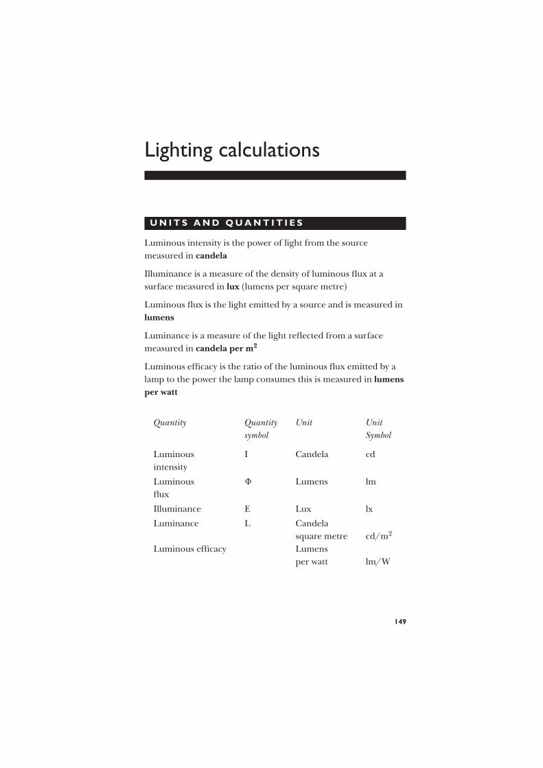
Lighting calculations
U N I T S A N D Q U A N T I T I E S
Luminous intensity is the power of light from the source
measured in candela
Illuminance is a measure of the density of luminous flux at a
surface measured in lux (lumens per square metre)
Luminous flux is the light emitted by a source and is measured in
lumens
Luminance is a measure of the light reflected from a surface
measured in candela per m2
Luminous efficacy is the ratio of the luminous flux emitted by a
lamp to the power the lamp consumes this is measured in lumens
per watt
Quantity Quantity Unit Unit
symbol Symbol
Luminous I Candela cd
intensity
Luminous 8 Lumens lm
flux
Illuminance E Lux lx
Luminance L Candela
square metre cd/m2
Luminous efficacy Lumens
per watt lm/W
149

I N V E R S E S Q U A R E L A W
When using the inverse square law, the distance used in the
measurement is from the light source to a point directly below it.
When a lamp is suspended above a surface, the illuminance at
a point below the lamp can be calculated:
Illuminance E = (I ) candela
distance2lux
= I
d2
EXAMPLE 1 A luminaire producing a luminous intensity of
1500 candela in all directions below the horizontal, is suspended
4m above a surface. Calculate the illuminance produced on the
surface immediately below the luminaire.
1500 CD
D
E
4 m
Fig. 81
E = I
d2
= 1500
42
= 93.75 lux
EXAMPLE 2 If the luminaire in Example 1 is raised by 1m, what
would the new illuminance be at the point immediately below the
surface?
150

E = 1500
(4 + 1)2
= 1500
52
= 60 lux
C O S I N E L A W
When using the cosine law, the distance used is from the light
source measured at an angle to the point at which the lux value is
required.
When a lamp is suspended above a horizontal surface, the
illuminance (E) at any point below the surface can be calculated.
E = I
h2cos φ
CD
D
X
h
Fig. 82
To calculate h2 (distance from lamp)
h2 = d2 + x2
To calculate cos φ
cos φ = d
h
151

EXAMPLE 1 A light source producing 1500 candela is
suspended 2.2m above a horizontal surface. Calculate the
illumination produced on the surface 2.5m away (Q)
Calculate h2 using pythagoras.
h2 = d2 + x2
= 2.22 + 2.52
h2 = 11.09
Calculate h
=√
h2
= 3.33
Calculate cos φ using pythagoras
= d
h
= 2.2
3.33
= 0.66
EQ = 1500
11.09× 0.66
= 89.26 lux
CD
2.2
2.5
3.3
Fig. 83
152

EXAMPLE 2 Two lamps are suspended 10m apart and at a
height of 3.5m above a surface (Figure 84). Each lamp emits
350cd. Calculate.
(a) the illuminance on the surface midway between the lamps,
(b) the illuminance on the surface immediately below each of the
lamps.
x = 5 m
d = 3.5 m
x = 5 mPA
Q
PB
350 cdB
350 cdA
θ ′θ
d
h ′hh
Fig. 84
(a) For one lamp, the illuminance at Q is
EQ = I
h2cos θ
= 350
3.52 + 52× 3.5√
(3.52 + 52)
= 350
12.25 + 25× 3.5√
(12.25 + 25)
= 350
37.25× 350√
37.25
= 5.388 lx
The illuminance from two lamps is double that due to one lamp,
since the conditions for both lamps are identical. Thus
total illuminance at Q = 2 × 5.388
= 11.8 lx
153

(b) At PA below lamp A, the illuminance due to lamp A is
EPA = I
d2
= 350
3.52
= 28.57 lx
In calculating the illuminance at PA due to lamp B, we have a new
distance h′, a new distance x′, and a new angle θ ′ to consider.
x′ = 2x
= 10
(h′)2 = 3.52 + 102
= 112.25
∴ (h′) = 10.59
cos θ ′ = d
h′
= 3.5
10.59= 0.331
∴ illuminance at PA due to lamp B is
EPB = 350
112.25× 0.331
= 1.013
Total illuminance at PA = 28.57 + 1.013
= 29.61 lx
and, as the conditions at PB are the same as those at PA, this will
also be the illuminance below lamp B.
EXERCISE 19
1. A lamp emitting 250cd in all directions below the
horizontal is fixed 4m above a horizontal surface. Calculate
the illuminance at (a) a point P on the surface vertically
beneath the lamp, (b) a point Q 3m away from P.
154
2. Two luminaires illuminate a passageway. The luminaires
are 12m apart. Each emits 240cd and is 3m above the
floor. Calculate the illuminance at a point on the floor
midway between the luminaires.
3. Determine the illuminance at a point vertically beneath one
of the luminaires in question 2.
4. An incandescent filament luminaire is suspended 2m
above a level work bench. The luminous intensity in all
directions below the horizontal is 400candelas.
Calculate the illuminance at a point A on the surface of
the bench immediately below the luminaire, and at other
bench positions 1m, 2m and 3m from A in a straight line.
Show the values on a suitable diagram. (CGLI)
5. Two incandescent filament luminaires are suspended 2m
apart and 2.5m above a level work bench. The luminaires
give a luminous intensity of 200 candelas in all directions
below the horizontal. Calculate the total illuminance at
bench level, immediately below each luminaire and midway
between them.
6. A work bench is illuminated by a luminaire emitting 350cd
in all directions below the horizontal and mounted 2.5m
above the working surface.
(a) Calculate the illuminance immediately below the
luminaire.
(b) It is desired to increase the illuminance by 10%.
Determine two methods of achieving this, giving
calculated values in each case.
7. A lamp emitting 450cd in all directions is suspended 3m
above the floor. The illuminance on the floor immediately
below the lamp is
(a) 150 lx (b) 1350 lx (c) 50 lx (d) 0.02 lx
8. If the lamp of question 7 is reduced in height by 0.5m, the
illuminance produced immediately below it is
(a) 72 lx (b) 36.7 lx (c) 129 lx (d) 180 lx
155

Mechanics
M O M E N T O F F O R C E
The moment of force about a point is found by multiplying
together the force and the perpendicular distance between the
point and the line of action of the force.
Consider an arm attached to a shaft as in Figure 85. The
moment acting on the shaft tending to turn it clockwise is
2 N × 0.5 m = 1 Nm
0.5 m
2 N
Fig. 85
T O R Q U E
If in Figure 85 a turning effect is applied to the shaft in the
opposite direction so that the arm is maintained in a horizontal
position, then the torque exerted at the shaft is 1Nm.
Consider now an electric motor fitted with a pulley 0.25m in
diameter over which a belt passes to drive a machine (Figure 86).
If the pull on the tight side of the belt is 60N when the motor is
running, then a continuous torque of
60 N × 0.25 m
2= 7.5 Nm is present
156

0.25m
60N
Fig. 86
This ignores any pull on the slack side of the belt, and this must
usually be taken into account. Thus, if the tension in the slack side
of the belt is say 10N, then the net torque exerted by the motor is
(60 − 10) N × 0.25 m
2= 50 × 0.25 Nm
2
= 6.25 Nm
In general the torque exerted is
T = (F1 − F2) × r Nm
where F1 is the tension in the tight side, F2 is the tension in the
slack side (in newtons), and r is the pulley radius (in metres).
P O W E R
P = 2pnT watts
where T is the torque in newton metres and n is the speed of the
pulley in revolutions per second.
EXAMPLE 1 If the pulley previously considered is running at
16rev/s, calculate the power output of the motor.
P = 2pnT
= 2p × 16 × 6.25
= 629 W
157

EXAMPLE 2 Calculate the full-load torque of a 3kW motor
running at 1200rev/min.
1200 rev/min = 1200
60= 20 rev/s
P = 2pnT
∴ 3 × 1000 = 2p × 20 × T(note conversion of
kW to W)
∴ T = 3 × 1000
2p × 20
= 23.9 Nm
EXAMPLE 3 During a turning operation, a lathe tool exerts a
tangential force of 700N on the 100mm diameter workpiece.
(a) Calculate the power involved when the work is rotating at
80rev/min.
(b) Calculate the current taken by the 230V single-phase a.c.
motor, assuming that the lathe gear is 60% efficient, the
motor is 75% efficient, and its power factor is 0.7.
The arrangement is shown in Figure 87.
(a) The torque exerted in rotating the work against the tool is
T = 700 N × 0.05 m(note: radius is
50mm = 0.05m)
= 35 Nm
P = 2pnT
= 2p × 80 × 35
60
(note: conversion of rev/min to
rev/s)
= 293 W
230 V MotorGear
700 N
Tool
100 mm
dia
I
Fig. 87
158

(b) Motor output = 293 × 100
60
= 488 W
Motor input = 488 × 100
75
= 650.6 W
P = V × I × p.f .
∴ 650.6 = 230 × I × 0.7
∴ motor current I = 650.6
230 × 0.7
= 4.04 A
S U R F A C E S P E E D , P U L L E Y D I A M E T E R
A N D S P E E D R A T I O S
EXAMPLE 1 When turning a piece of low-carbon steel, it should
be rotated so that the speed of its surface in relation to the tool is
about 0.35m/s. Determine the speed at which a bar 120mm in
diameter should be rotated in order to achieve this surface speed.
Consider a point on the surface of the steel (Figure 88). In one
revolution, this point moves through a distance equal to the
circumference of the bar.
i.e. distance moved in one revolution = p × D
= 3.142 × 120
1000
= 0.377 m
D
Fig. 88
159

Number of revolutions required for 0.35 m = 0.35
0.377
= 0.9285
∴ speed of rotation = 0.928 rev/s
EXAMPLE 2 A machine is driven at 6rev/s by a belt from a
standard motor running at 24rev/s. The motor is fitted with a
200mm diameter pulley. Find the size of the machine pulley.
The speeds at which the pulleys rotate are inversely proportional
to their diameters. Thus, if the pulley having a diameter of D1
rotates at n1 rev/min and the pulley having a diameter of D2
rotates at n2 rev/min (Figure 89), then
n1
n2= D2
D1
In this case,
24
6= D2
200
∴ D2 = 200 × 24
6
= 800 mm
n1
n2
D1D2
Fig. 89
EXERCISE 20
1. A motor drives a machine by means of a belt. The tension
in the tight side of the belt is 100N, that in the slack side is
160

40N, and the pulley is 200mm in diameter. Calculate the
total torque exerted by the motor.
2. A test on an induction motor fitted with a prony brake
yielded the following results:
Tension in tight
side of belt (N) 0 20 30 40 50 60
Tension in slack
side of belt (N) 0 4 6 8.75 11.5 14.5
Speed (rev/min) 1450 1440 1430 1410 1380 1360
Calculate the torque and power corresponding to each set
of readings. Take the pulley radius as being 100mm.
3. A 10kW motor fitted with a 250mm diameter pulley runs
at 16rev/s. Calculate the tension in the tight side of the
belt. Ignore any tension in the slack side.
4. A 4kW motor fitted with a 150mm diameter pulley runs at
24rev/s. The tension in the tight side of the belt may be
assumed to be equal to three times the tension in the slack
side. Determine the tension in each side of the belt at
full load.
5. Calculate the full-load torque of each of the motors to
which the following particulars refer:
Rated power (kW) Normal speed (rev/min)
(a) 10 850
(b) 2 1475
(c) 18 750
(d) 0.25 1480
(e) 4 1200
6. A motor exerts a torque of 25Nm at 16rev/s. Assuming
that it is 72% efficient, calculate the current it takes from
a 440V d.c. supply.
161

7. A brake test on a small d.c. motor, pulley diameter 75mm,
gave the following results:
Net brake
tension (N) 0 5 10 15 20 25
Speed (rev/min) 1700 1690 1680 1670 1650 1640
Current (A) 0.8 1.05 1.3 1.68 1.9 2.25
Supply voltage (V) 116 116 116 116 116 116
For each set of values, calculate the power output and the
efficiency. Plot a graph of efficiency against power.
8. The chuck of a lathe is driven at 2rev/s through a gear
which is 60% efficient from a 240V d.c. motor. During the
turning operation on a 75mm diameter workpiece, the
force on the tool is 300N. Calculate the current taken by
the motor, assuming its efficiency is 70%.
9. Calculate the speed at the circumference of a 250mm
diameter pulley when it is rotating at 11rev/s.
10. A motor drives a machine through a vee belt. The motor
pulley is 120mm in diameter. Calculate the speed at which
the belt travels when the motor runs at 24rev/s.
11. The recommended surface speed for a certain type of
grinding wheel is about 20m/s. Determine the speed at
which a 250mm diameter wheel must rotate in order to
reach this speed.
12. For a certain type of metal, a cutting speed of 0.6m/s is
found to be suitable. Calculate the most suitable speed, in
revolutions per minute, at which to rotate bars of the metal
having the following diameters in order to achieve this
surface speed: (a) 50mm, (b) 125mm, (c) 150mm,
(d) 200mm, (e) 75mm.
13. A circular saw is to be driven at 60rev/s. The motor is a
standard one which runs at 1420rev/min and is fitted with
a 200mm diameter pulley. Determine the most suitable size
pulley for driving the saw.
162

(a)
(b)
225 mm
300 mm
125 mm1350 rev/min
9 rev/s200 mm
Fig. 90
14. (a) Calculate the speed of the smaller pulley in Figure 90(a).
(b) Determine the speed, in rev/min, of the larger pulley in
Figure 90(b).
15. Calculate the diameter of the larger pulley in Figure 91(a)
and (b).
3500 rev/min
11 rev/sD = ?
D = ?
16 rev/s
140 rev/min
(a)
(b)
200mm
75mm
Fig. 91
16. A cutting tool exerts a tangential force of 300N on a steel
bar 100mm in diameter which is rotating at 160rev/min in
a lathe. The efficiency of the lathe gearing is 62% and that
163

of the 240V a.c. driving motor is 78%. Calculate the
current taken by the motor if its power factor is 0.6.
The pulley on the lathe which takes the drive from the
motor is 225mm in diameter and rotates at 600rev/min.
The motor runs at 1420rev/min. What is the diameter of
the motor pulley?
164

Miscellaneous examples
D . C . G E N E R A T O R S
U = E − IaRa
where U is the terminal voltage,
E is the generated e.m.f.,
Ia is the armature current,
and Ra is the armature resistance.
EXAMPLE Calculate the e.m.f. generated by a shunt generator
which is delivering 15A at a terminal voltage of 440V. The
armature circuit resistance is 0.15 Ä, the resistance of the shunt
field is 300 Ä, and a voltage drop of 2V occurs at the brushes.
The circuit is shown in Figure 92.
U = 440 VRo = 0.15 ΩRs = 300 Ω
15 A
Io
Is
Fig. 92
To find the shunt field current,
U = Is × Rs
165

where Is is shunt field current,
and Rs is shunt field resistance.
∴ 440 = Is × 300
∴ Is = 440
300
= 1.47A
Total armature current = 15 + 1.47
= 16.47 A
Neglecting the voltage drop at the brushes,
U = E − IaRa
∴ 440 = E − 16.47 × 0.15
= E − 2.47
∴ 440 + 2.47 = E
E = 442.47 V
Allowing for the voltage drop at the brushes,
generated e.m.f . = 442.47 + 2
= 444.47
= 444 V
D . C . M O T O R S
U = E + IaRa
where U is the terminal voltage,
E is the back e.m.f.,
Ia is the armature current,
and Ra is the circuit resistance.
EXAMPLE Calculate the back e.m.f. of a d.c. motor which
is taking an armature current of 25A from a 220V supply.
166

The resistance of its armature is 0.2 Ä.
U = E + IaRa
∴ 220 = E + 25 × 0.2
= E + 5.0
∴ 220 − 5 = E
∴ E = 215 V
A L T E R N A T O R S A N D S Y N C H R O N O U S
M O T O R S
f = n × p
where f is the frequency in hertz,
n is the speed in revolutions per second,
and p is the number of pairs of poles.
EXAMPLE 1 Calculate the number of poles in an alternator
which generates 60Hz at a speed of 5rev/s.
f = n × p
∴ 60 = 5 × p
∴ p = 60
5
= 12
∴ the machine has 2 × p = 24 poles
EXAMPLE 2 Calculate the speed at which a four-pole
synchronous motor will run from a 50Hz supply.
f = n × p
∴ 50 = n × 2 (4 poles gives 2 pairs)
∴ n = 50
2
= 25 rev/s
167

I N D U C T I O N M O T O R S
Percentage slip = ns − nr
ns× 100%
where ns is the synchronous speed,
and nr is the actual speed of the rotor.
The synchronous speed ns can be determined from the
relationship
f = ns × p
as in the case of the synchronous motor.
EXAMPLE Calculate the actual speed of a six-pole
cage-induction motor operating from a 50Hz supply with 7% slip.
f = ns × p
∴ 50 = ns × 3
∴ ns = 50
3
= 16.7 rev/s
Percentage slip = ns − nr
ns× 100
∴ 7 = 16.7 − nr
16.7× 100
0.07 = 16.7 − nr
16.7
∴ 0.07 × 16.7 = 16.7 − nr
∴ nr = 16.7 − 0.07 × 16.7
= 15.5 rev/s
I N S U L A T I O N R E S I S T A N C E
The insulation resistance of a cable is inversely proportional to its
length.
168

EXAMPLE 1 The insulation resistance measured between the
cores of a certain twin cable 100m long is 1000 MÄ. Calculate the
insulation resistance of 35m of the same cable.
The shorter length will have a higher value of insulation resistance
because the path for the leakage current has less cross-sectional
area (Figure 93).
Core
Core
Insulation
100 m
35 m
Tester
Fig. 93
Insulation resistance of 100 m = 1000 MÄ
∴ insulation resistance of 35 m = 1000 ×100 (larger)
35 (smaller)
= 2857 Ä
EXAMPLE 2 The insulation resistance measured between the
cores of a certain twin cable is 850 MÄ. Calculate the insulation
resistance obtained when two such cables are connected (a) in
series, (b) in parallel.
It is seen from Figure 94 that the effect in both cases is the same,
i.e. to increase the c.s.a. of the leakage-current path through
Tester
850 MΩ 850 MΩ
Tester
(a) Cables in series
(b) Cables in parallel
Core
Core
Core
Core
Core
Core
Insulation
Fig. 94
169

the insulation. The insulation resistance in either case is thus
850 MÄ
2= 425 MÄ
EXERCISE 21
1. What is meant by the expression ‘back e.m.f.’ of a
direct-current motor? In what way does the back e.m.f.
affect the starting of a direct-current motor?
A direct-current motor connected to a 460V supply takes
an armature current of 120A on full load. If the armature
circuit has a resistance of 0.25 Ä, calculate the value of the
back e.m.f. at this load. (CGLI)
2. A d.c. machine has an armature resistance of 8 Ä. Calculate
(a) the back e.m.f. when it is operating from a 110V supply
and taking an armature current of 2.5A;
(b) the e.m.f. generated when the machine is running as a
generator and delivering 2A at a terminal voltage of
110V. (Neglect the field current.)
3. A d.c. motor connected to a 460V supply has armature
resistance of 0.15 Ä. Calculate
(a) the value of the back e.m.f. when the armature current
is 120A,
(b) the value of the armature current when the back e.m.f.
is 447.4V. (CGLI)
4. Explain briefly, with the aid of diagrams, the differences
between series, shunt, and compound d.c. generators.
A d.c. shunt generator delivers a current of 96A at 240V.
The armature resistance is 0.15 Ä, and the field winding has
a resistance of 60 Ä. Assuming a brush contact drop of 2V,
calculate (a) the current in the armature, (b) the generated
e.m.f. (CGLI)
5. Calculate the speed at which an eight-pole alternator must
be driven in order to generate 50Hz.
170

6. Calculate the frequency of the voltage generated by a
four-pole alternator when it is running at (a) 16rev/s,
(b) 12rev/s.
7. Determine the speed at which a six-pole synchronous
motor will run from the 50Hz mains.
8. The synchronous speed of an induction motor is
750rev/min. The motor actually runs at 715rev/min.
Calculate the percentage slip.9. A four-pole induction motor is operating at 24rev/s from a
50Hz supply. Calculate the percentage slip.
10. A cage-induction motor having six poles operates with a
4.5% slip from a 50Hz supply. Calculate the actual rotor
speed.11. Calculate the full-load torque of a 30kW six-pole 50Hz
induction motor, assuming that the slip at full load
amounts to 5%.
12. Explain the term ‘insulation resistance’. Describe, with
wiring diagram, a suitable instrument for measuring
insulation resistance.
Calculate the insulation resistance of a 100m coil of
insulated cable. The insulation resistance of 1km of the
same cable is given as 2500 MÄ.13. The insulation resistance of 1000m of two-core cable is
1500 MÄ. Calculate the insulation resistance of
(a) 100m (b) 200m (c) 400m (d) 600m (e) 800m
and plot a graph showing the relationship between cable
length and insulation resistance.
14. Explain the term ‘insulation resistance of an installation’.
Describe, with connection diagram, the working of an
instrument suitable for measuring insulation resistance.
Three separate circuits are disconnected from a
distribution board and tested for insulation resistance to
earth. The respective values are 40 MÄ, 60 MÄ, and
300 MÄ. What is the combined insulation resistance to
earth? (CGLI)
15. The insulation resistance measured between the cores of a
certain twin cable is 950 Ä. Calculate the insulation
resistance of three identical cables connected in parallel.
171

16. The resistance of an armature circuit of a motor is 1.2 Ä.
The current through it is 15A and the terminal voltage is
200V. The generated e.m.f. is
(a) 218V (b) 182V (c) 13.3V (d) 125V
17. An alternator generates 400Hz at a speed of 500rev/min.
The number of pairs of poles is
(a) 12 (b) 48 (c) 6 (d) 3
18. The insulation resistance measured between the cores of a
cable is 900 MÄ for a 500m length. The insulation
resistance for 350m of this cable would be:
(a) 1285.7 MÄ (b) 630 MÄ (c) 157.5 × 10⁶ MÄ (d) 194.4 MÄ
172

Formulae
Voltage U = I × R
Current I = U
R
Resistance R = U
I
Power P = U × I
Power loss P = I2R
Current I = P
U
Voltage U = P
I
Resistors in
parallel
1
R1+ 1
R2+ 1
R3= 1
R∴ R
Area of a circle
(mm2 or m2)
p × d2
4= c.s.a.
Circumference of a circle
(mm or m)
p × d = C
Area of triangle
(mm2 or m2)
1
2base × height
Resistance of a copper
conductor (Ä)
1.78 × 10⁻⁸ × L
c.s.a. × 10−6= R
(where c.s.a. is in mm2)
Resistance of an
aluminium conductor (Ä)
2.84 × 10⁻⁸ × L
c.s.a. × 10−6= R
(where c.s.a. is in mm2)
Transformer calculationUp
Us=
Np
Ns= Is
Ip
Transformer efficiencypower out
power in= per unit × 100 (for %)
173

W O R K
W = f × d Work in N/m = force in Newtons × distance in mm
or m 1 kg = 9.81 Newtons
P = W
tor
Work done (Nm)
Time (secs)= Power in watts
J = W × t or Energy (joules) = Watts × time in seconds
E = Output
Input× 100 Efficiency in %
C A P A C I T A N C E
Charge of a capacitor is in coulombs Q = CU
Total charge of more than one capacitor Q = Q 1 + Q 2 + Q 3 etc.
or capacitance isQ
UFarads
Total capacitance of series connected1
C1+ 1
C2+ 1
C3etc.= 1
CT=C
Total capacitance of parallel connected C1+C2+C3 etc.=C
Energy stored in a capacitive circuit
Energy W = 1
2CV 2 Joules
Energy stored in an inductive circuit
Energy W = 1
2LI2 Joules (where L is in henrys)
T H R E E - P H A S E C A L C U L A T I O N S
Ip = phase current
IL = line current
UL = line voltage
UP = phase voltage
174

I N S T A R ( O N L Y O N E C U R R E N T )
IP = IL
UP = UL√3
UL = UP
√3
P =√
3×UL×IL
IL = P√3×UL
I N C I R C U I T S W I T H P O W E R F A C T O R
P =√
3×UL×IL×cosφ
IL = P√3×UL×cosφ
I N D E L T A ( O N L Y O N E V O L T A G E )
UL = UP
IP = IL√3
IL = IP ×√
3
P =√
3×UL×IL
I N C I R C U I T S W I T H P O W E R F A C T O R
P =√
3×UL×IL×cosφ
IL = P√3×UL×cosφ
Power factor cosθ = True power
Apparent power= Watts
Volt×amps
175
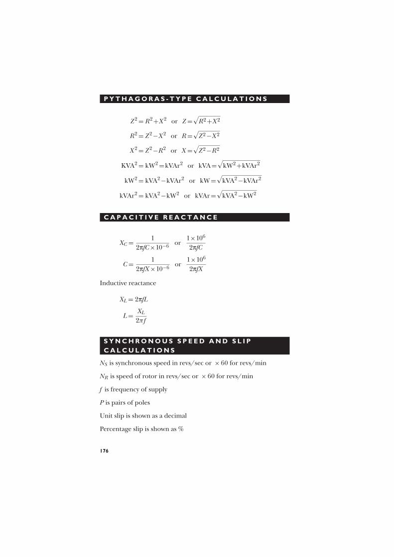
P Y T H A G O R A S - T Y P E C A L C U L A T I O N S
Z2 = R2+X2 or Z =√
R2+X2
R2 = Z2−X2 or R=√
Z2−X2
X2 = Z2−R2 or X =√
Z2−R2
KVA2 = kW2 =kVAr2 or kVA=√
kW2+kVAr2
kW2 = kVA2−kVAr2 or kW=√
kVA2−kVAr2
kVAr2 = kVA2−kW2 or kVAr=√
kVA2−kW2
C A P A C I T I V E R E A C T A N C E
XC = 1
2pfC×10−6or
1×10⁶
2pfC
C = 1
2pfX ×10−6or
1×10⁶
2pfX
Inductive reactance
XL = 2pfL
L= XL
2π f
S Y N C H R O N O U S S P E E D A N D S L I P
C A L C U L A T I O N S
NS is synchronous speed in revs/sec or × 60 for revs/min
NR is speed of rotor in revs/sec or × 60 for revs/min
f is frequency of supply
P is pairs of poles
Unit slip is shown as a decimal
Percentage slip is shown as %
176

S Y N C H R O N O U S S P E E D
NS = f
Pin revs per sec×60 for rpm
R O T O R S P E E D
NS −NR
NS=unit slip×100 for %
C A L C U L A T I O N S A S S O C I A T E D W I T H
C A B L E S E L E C T I O N
It ≥ IN
Correction factors
Cable resistance at 20C R= r1+r2×length in mÄ
1000
Volt drop in cablemV×amperes×length
1000
Earth fault loop impedance Zs =Ze = (R1+R2)
177

Glossary
a.c. Alternating current
Area Extent of a surface
BS 7671 British standard for electrical wiring
regulations
Capacitive
reactance
The effect on a current flow due to the
reactance of a capacitor
Circle Perfectly round figure
Circuit breaker A device installed into a circuit to
automatically break a circuit in the event of
a fault or overload and which can be reset
Circuit Assembly of electrical equipment which is
supplied from the same origin and
protected from overcurrent by a protective
device
Circumference Distance around a circle
Conductor Material used for carrying current
Coulomb Quantity of electrons
Correction
factor
A factor used to allow for different
environmental conditions of installed
cables
C.S.A. Cross-sectional area
Current Flow of electrons
Cycle Passage of an a.c. waveform through 360
Cylinder Solid or hollow, roller-shaped body
d.c. Direct current
Dimension Measurement
Earth fault
current
The current which flows between the earth
conductor and live conductors in a circuit
178

Earth fault loop
impedance
Resistance of the conductors in which the
current will flow in the event of an earth
fault. This value includes the supply cable,
supply transformer and the circuit cable
up to the point of the fault
Efficiency The ratio of output and input power
Energy The ability to do work
E.M.F. Electromotive force in volts
Frequency Number of complete cycles per second of
an alternating wave form
Fuse A device installed in a circuit which melts to
break the flow of current in a circuit
Force Pull of gravity acting on a mass
Hertz Measurement of frequency
Impedance Resistance to the flow of current in an
a.c. circuit
Impedance
triangle
Drawing used to calculate impedance in an
a.c. circuit
Internal
resistance
Resistance within a cell or cells
Kilogram unit of mass
kW True power (×1000)
kVA Apparent power (×1000)
kVAr Reactive power (×1000)
Load Object to be moved
Load The current drawn by electrical equipment
connected to an electrical circuit
Mutual
induction
Effect of the magnetic field around a
conductor on another conductor
Magnetic flux Quantity of magnetism measured in
Webers
Magnetic flux
density
Is the density of flux measured in Webers
per metre squared or Tesla
Newton Pull of gravity (measurement of force)
On-Site Guide Publication by the IEE containing
information on electrical installation
Ohm Unit of resistance
179

Overload
current
An overcurrent flowing in a circuit which is
electrically sound
Percentage
efficiency
The ratio of input and output power
multiplied by 100
Power Energy used doing work
Pressure Continuous force
Primary
winding
Winding of transformer which is connected
to a supply
Perimeter Outer edge
Potential
difference
Voltage difference between conductive parts
Prospective
short circuit
current
The maximum current which could flow
between live conductors
Prospective
fault current
The highest current which could flow in a
circuit due to a fault
Protective
device
A device inserted into a circuit to protect the
cables from overcurrent or fault currents
Resistor Component which resists the flow of
electricity
Resistance Opposition to the flow of current
Resistivity Property of a material which affects its
ability to conduct
Rectangle Four-sided figure with right angles
Space factor Amount of usable space in an enclosure
Secondary
winding
Winding of transformer which is connected
to a load
Self-induction Effect of a magnetic field in a conductor
Series Connected end to end
Thermoplastic Cable insulation which becomes soft when
heated and remains flexible when cooled
down
Transpose Change order to calculate a value
Triangle Three-sided object
Thermosetting Cable insulation which becomes soft when
heated and is rigid when cooled down
180

Transformer A device which uses electromagnetism to
convert a.c. current from one voltage to
another
Voltage drop Amount of voltage lost due to a resistance
Volume Space occupied by a mass
Wattmeter Instrument used to measure true power
Waveform The shape of an electrical signal
Work Energy used moving a load (given in
Newton metres or joules)
Phasor Drawing used to calculate electrical values
181

Answers
Exercise 1
1. Volts V (a.c.) 10 225 230 400 100 25 230 625
Current (A) 0.1 15 0.5 0.4 0.01 500 180 25
Impedance (Ä) 100 15 460 1000 10000 0.05 1.3 25
2. Current (A) 1.92 3.84 18.2 2.38 7.35 4.08 4.17 8.97
Volts V (a.c.) 4.7 7.5 225.7 230 107 228.5 400 235
Impedance (Ä) 2.45 1.95 12.4 96.3 14.56 56 96 26.2
3. Impedance (Ä) 232 850 695.6 0.125 29.85 1050 129 4375
Volts V (a.c.) 176.3 230 400 26.5 0.194 457.8 238 245
Current (A) 0.76 0.27 0.575 212 0.0065 0.436 1.84 0.056
4. 101 Ä 5. 1.096 A 6. (a) 2.18 Ä, (b) 4.49 Ä
7. (a) 0.472 Ä, (b) 3.83 Ä, (c) 0.321 Ä, (d) 13 Ä, (e) 0.413 Ä
8. 84.3 Ä
9. Volts V (a.c.) 61.1 105 153 193 230
Current (A) 2.3 4.2 6.12 7.35 9.2
Impedance (Ä) 26.56 25 25 26.26 25
10. (b) 11. (c) 12. (d)
Exercise 2
1. 4.71Ä 2. 0.478H
3. Inductance (H) 0.04 0.159 0.12 0.008 0.152
Frequency (Hz) 50 50 48 90 60
Reactance (Ä) 12.57 50 36 4.5 57
4. (a) 40.8Ä, (b) 0.13H 5. (a) 15.97A, (b) 13.07A
6. (a) 3.77 Ä, (b) 2.2 Ä, (c) 0.141 Ä, (d) 0.11 Ä, (e) 14.1 Ä
7. (a) 0.955 H, (b) 0.0796 H, (c) 0.0462 H, (d) 0.398 H,
(e) 0.0159 H
10. 398V 11. (a) 12. (c)
182

Exercise 3
1. (a) 53 Ä, (b) 127 Ä, (c) 79.6 Ä, (d) 21.2 Ä, (e) 397 Ä,
(f) 265 Ä, (g) 12.7 Ä, (h) 33.5 Ä, (i) 199 Ä, (j) 42.4 Ä
2. (a) 13.3 mF, (b) 42.4 mF, (c) 265 mF, (d) 703 mF, (e) 88.4 mF,
(f) 199 mF, (g) 70.8 mF, (h) 7.96 mF, (i) 106 mF, (j) 44.2 mF
3. 346 mF
7. 207.6 mF
10. 15.2 A
4. 6.36 mF
8. 364 V
11. (d)
6. 159 V
9. 10 A
12. (a)
Exercise 4
1. R 15 25 3.64 47.44 4.32 6.32 76.4 0.54
R2 225 625 13.25 2250 18.7 40 5837 0.735
2. X 29.8 0.68 0.16 0.95 0.4 897 233.7 0.197
X2 888 0.46 0.026 0.9 0.16 804609 54616 0.039
3. 6.71 A 4. 8.69 A
5. R (Ä) 14.5 140 9.63 3.5 57.6 94.8
X (Ä) 22.8 74.6 15.68 34.7 4050 49.6
Z (Ä) 27.02 159 18.4 34.87 4050 107
6. 232 Ä 7. 17.46 mF 8. (a) 16.9 Ä, (b) 73.3 Ä, (c) 71.3 Ä
9. 0.13 H, 115 V 10. (a) 28.75 Ä, (b) 0.122 H, (c) 47.9 Ä
11. 18.93 Ä, 15.04 Ä, 0.0479 H, 11.5 Ä 13. 69 mF
14. 0.318 H, 38.9 mF, 45.3 Hz 15. 14.57 A
16. (a) 7.47 A, (b) 127 mF 17. (c) 18. (c)
Exercise 5
1. 50 Ä 2. 40.1 Ä 3. 50 Ä 4. 198 Ä 5. 46.3 Ä
6. 231 Ä 7. 28 Ä 8. 1.09 Ä 9. 355 Ä 10. 751 Ä
11. 283 Ä 12. Approx. 500 Ä
13. Angle φ 30° 45° 60° 90° 52°24′ 26°42′ 83°12′ 5°36′
sin φ 0.5 0.7071 0.8660 1 0.7923 0.4493 0.9930 0.0976
cos φ 0.8616 0.7071 0.5 0.0 0.6101 0.8934 0.1184 0.9952
tan φ 0.5774 1 1.7321 0.0 1.2985 0.5029 8.3863 0.0981
14. Angle φ 33°3′ 75°21′ 17°15′ 64°29′ 27°56′ 41°53′
sin φ 0.5454 0.9675 0.2965 0.9025 0.4684 0.6676
cos φ 0.8382 0.2529 0.9550 0.4308 0.8835 0.7445
tan φ 0.6506 3.8254 0.3105 2.0949 0.5302 0.8967
183

15. Angle φ 21°48′ 25°48′ 65°30′ 36°52′ 36°52′ 50°24′ 65°20′ 61°36′
sin φ 0.3714 0.4352 0.91 0.6 0.6 0.7705 0.9088 0.8797
cos φ 0.9285 0.9003 0.4146 0.8 0.8 0.6374 0.4172 0.4754
tan φ 0.4000 0.4835 2.1948 0.75 0.75 1.2088 2.1778 1.8505
16. Angle φ 75°3′ 64°16′ 5°25′ 38°34′ 29°38′ 72°24′ 72°23′ 71°27′
sin φ 0.9661 0.9008 0.0946 0.6234 0.4945 0.9532 0.9531 0.9481
cos φ 0.2582 0.4341 0.9955 0.7819 0.8692 0.3020 0.3026 0.318
tan φ 3.7346 2.0752 0.0950 0.7973 0.5689 3.152 3.15 2.9814
17. 21.3Ä,20Ä 18. 3.95Ä,6.13Ä 19. 3147′ 20. 90.9Ä,78Ä
21. 191W,162VAr 22. 3251′,129Ä 23. 2857′ 24. 66.6Ä
25. 37.6Ä 26. 37.627. Phase angle φ 7530′ 7230′ 656′ 60 5637′ 537′ 4540′ 3454′
Power factorcos φ 0.25 0.3 0.421 0.5 0.55 0.6 0.699 0.82
28. (a) 17.8Ä, (b) 0.03H, (c) 12.92A, (d) 0.844
29. 4Ä, 6.928Ä, 8Ä
Exercise 6
1. 230V 2. 31.1A,14.1A 4. 151V,44°30′ 5. 3.63A
Exercise 7
5. 248V 7. 1029Ä,2754Ä 8. 7kW,7.14kVA 9. 2130VA
10. 179W 11. 5.1A 12. 2.5A 13. 197V
Exercise 8
1. 0.47A(lead) 2. 3.4A,2755′ (lag),0.88(lag), 3.1.41A(lag)
4. 2.78A,0.86(lag) 5. 3.49A,0.92(lag) 6. 10.6µF 7. 1.71A
8. (b) 9. (c)
Exercise 9
1. 21.74A; (a) 4kW, (b) 3kW 2. 131kW, 141kVA
3. 6.72kW, 8.97kVA, 356µF 4. 11.5kVA, 4.6kW, 7.09kVAr
5. 13.8kVA, 6.9kW, 8.6kVAr, 37.39A 6. 29.24 A
7. 124 µF, 5.35A
184

8. Power factor 0.7 0.75 0.8 0.85 0.9 0.95 1.0
Capacitance
required µF 1137 1624 2109 2589 3092 3619 4825
9. 31.1A; (a) 414µF, (b) 239µF 10. Approx. 15µF 11. (b)
12. (a) 13. (b) 14. (c)
Exercise 10
1. (a) 4.62A, (b) 2561W 2. (a) 1.63A,(b) 1129W
3. (a) L1 = 9.2A, (b) L2 =17.69A, (c) L3 =11.51A
4. (a) 4.6A, (b) 3186W 5. (a) 23.09A,(b) 69.28A
6. (a) L1 20.99A, (b) L2 28.86A, (c) L3 24.93A
7. (a) 7.66A, 7.66A, 5.3kW, (b) 3.33A, 23.09A, 15.9kW
8. (a) 19.21A, (b) 13.3kW
9. (a) 5.17A, 6.2kW, (b) 2.97A, 2.06kW
10. (a) 2.16A, 0.468Lag, 1.5kW, (b) 6.49A, 0.468 Lag, 4.5kW
11. (a) 6.64Ä, (b) 20Ä 12. (a) 884µf, (b) 295µf
13. L1−L2 =6.66A, L2−L3 =8A, L1−L3 =12.6A, 14.1kW
14. (a) 6.09kW, (b) 22.6A 15. (a) 7.1kW, (b) 18.86A
16. (a) 17.86A, (b) 37.73A, (c) 26.14kW
17. (a) 17.6kV, (b) in delta VL =9.84A, VP =5.7A, in star VL and
VP =433.7A
Exercise 11
1. 5.29A 2. 15.35A 3. 17.32A
Exercise 12
1. 385V, 3.6%, 756W 2. (a) 410V, (b) 1160W 3. 12.14V
4. 95mm2 5. 467mm2,500mm2,4.61V 6. 5.8V 7. 70mm2
8. 25mm2 9. 70mm2 10. 14A
11. (a) 17.32A, (b) 20A, (c) 19.2mV/A/m, (d) 29.35A, (e) 6mm2,
(f) 3.79V, (g) 25mm
12. (a) (i) 1210A, (ii) 0.25s, (iii) 0.393W, (iv) 585.2A, (v) 3s;
(b) 0.44Ä
13. (a) (i) 62.36A, (ii) 63A, (iii) 3.2mV/A/m, (iv) 67.02A,
(v) 16mm2, (vi) 4.49V, (b) (i) 0.51Ä, (ii) 0.86Ä (Table 41D)
14. (a) 96.51A, (b) 100A, (c) (i) 97.08A, (ii) 70mm2, (iii) 1.82V
185

15. (a) 36.08A, (b) 40A, (c) 42.55A, (d) 2.92mV/A/m,
(e) 16mm2, (f) 8.22V
16. (a) 17.32A, (b) 20A, (c) 9.6mV/A/m, (d) 21.3A, (e) 4mm2,
(f) 4.94V, (g) 13.3A (satisfactory), (h) Table 5C factor=225,
Table 5D factor=260, satisfactory
Exercise 13
1. 40mV 2. 45.2Ä 3. 99975Ä 4. 1.5×10⁻³Ä
5. 9960Ä, 149960Ä, 249990Ä; 40×10−3Ä, 4×10⁻³ Ä 6. (c)
7. (d) 8. (a) 9. (b)
Exercise 14
1. (a) 44.36A, (b) 35.3A, (c) 36.1A, (d) 66A, (e) 79.3A, (f) 8.05A,
(g) 20.9A, (h) 59.1A
2. 84% 3. 85.3%, 0.76 4. 76.9%, 0.754 6. 18.23A 7. (d)
8. (a)
Exercise 15
1. 183.72A. Thermal storage is probably on its own installation,
if the shower could be on its own control, then normal 100A
consumer unit can be used.
2. 152.35A. Propose that the under sink heaters be on their own
consumer unit.
3. 230.32A. See paragraph 2 of IEE On-Site Guide. This is a
single-phase supply at present; consultation with the supplier
would be essential. Perhaps a poly-phase supply would be
available but could incur additional service cable costs.
4. 177.72A (approx. 60A per phase)
Exercise 16
1. 0.448Ä 2. 0.538Ä 3. 1.02Ä 4. Yes
5. (a) Yes, (b) Yes 6. 5.52 (6mm2) 7. (a) Phase 25mm2,
(b) C.P.C. 1.5mm2
Exercise 17
1. 8.6A 2. (a) 1.26V, (b) 888.2W 3. (a) 45A, (b) 55.6A, (c) 4.9V
4. (a) 13.04A, (b) 7.2V, (c) 5.86V, (d) 224.14V
186

5. (a) 75.76A, (b) 1.96V 6. (a) 2.22mV, (b) 25mm2, (c) 4.05V
7. (a) 60.87A, (b) 63A, (c) 105.5A, (d) 1.45mV/A/m,
(e) 35mm2, (f) 5.14V
8. (a) 43.5A, (b) 50A, (c) 64.73A, (d) 0.96mV/A/m, (e) 50mm2,
(f) 4.85V
9. (a) 28.58A, (b) 32A, (c) 34A, (d) 5.95mV/A/m, (e) 16mm2,
(f) 4V, (g) 32mm conduit
10. (a) 39.13A, (b) 4.47mV/A/m, (c) 40A, (d) 55.47A,
(e) 10mm2, (f) 229.14V, 227.93V, 226.56V
11. (a) 21.74A, (b) 25A, (c) 25A, (d) 19.2mV/A/m, (e) 4.0mm2,
(f) 4.18V
12. (a) 27.95A, (b) 9.2V, (c) 30A, (d) 30A, (e) 8.22mV/A/m,
(f) 8.16V
13. (a) 34.78A, (b) 40A, (c) 40A, (d) 6.0mm2, (e) 4.44V
14. (a) 42.45A, (b) 63.7A, (c) 96.8A, (d) 10mV/A/m, (e) 50mm2,
(f) 3.01V
15. (b) 16. (b) 17. (a) 18. (c) 19. (d)
Exercise 18
1. (a) 0.715Ä, (b) 1.02Ä 2. (a) 1.0Ä, (b) 4.51Ä
3. (a) 0.594Ä, (b) 6.56Ä 4. (a) 0.566Ä, (b) 0.84Ä, (c) 0.3s
5. (c) 6. (c) 7. (b)
Exercise 19
1. (a) 15.6 lx, (b) 8 lx 2. 4.77lx 3. 27lx
4. 100lx, 71.6 lx, 35.4 lx, 17.1 lx 5. 47.2 lx, 51.2 lx
6. (a) 56lx, (b) new lamp of 385cd or same lamp, new height
2.38m
7. (c) 8. (a)
Exercise 20
1. 6Nm
2. Torque (Nm) 0 1.6 2.4 3.125 3.85 4.55
Power (W) 0 241.3 359 461 556 6483. 795N 4. 531N, 177N
5. (a) 112Nm, (b) 13Nm, (c) 229Nm, (d) 1.61Nm, (e) 31.8Nm
187

6. 7.94A
7. Po (W) 0 33.2 66.0 98.4 130 161
n (%) 0 27.2 43.7 50.5 58.8 61.78. 1.4A 9. 8.64m/s 10. 9.05m/s 11. 25.5rev/s
12. (a) 229rev/min, (b) 91.7rev/min, (c) 76.4rev/min,
(d) 57.3rev/min, (e) 153rev/min
13. 78.8mm 14. (a) 13.5rev/s, (b) 750rev/min
15. (a) 291mm, (b) 181mm 16. 3.61A, 95mm
Exercise 21
1. 430V 2. (a) 90V, (b) 126V 3. (a) 442V, (b) 84A
4. (a) 100A, (b) 257V 5. 12.5rev/s 6. (a) 32Hz, (b) 24Hz
7. 16.7rev/s 8. 4.67% 9. 4% 10. 15.9rev/s 11. 301.5Nm
12. 25000MÄ
13. (a) 15000MÄ, (b) 7500MÄ, (c) 3750MÄ, (d) 2500MÄ,
(e) 1875MÄ
14. 22.2MÄ 15. 317Ä 16. (b) 17. (b) 18. (b)
188


